
CliQ II Redundancy Modules 20A / DRR-20 , 40A / DRR-40 · CliQ II Redundancy Modules 20A / DRR-20 ,...
13
TECHNICAL DATASHEET CliQ II Redundancy Modules 20A / DRR-20□, 40A / DRR-40□ All parameters are specified at 25°C ambient and AC input unless otherwise indicated. www.DeltaPSU.com (December 2018, Rev. 05) 1 Highlights & Features • Wide input and output range of 22-60Vdc • Very wide operating temperature from -40°C to +80°C • Built-in 2 channel DC OK signal and alarm relay contact • Support N+1 Redundancy connection • Conformal coating on PCBA to protect against chemical and dust pollutants • Hazardous Locations approval to ATEX and Class I, Div 2 (DRR-20A and DRR-40A) Safety Standards CB Certified for worldwide use Model Number: DRR-20☐, DRR-40☐ Unit Weight: 0.38 kg (0.84 lb), 0.52 kg (1.15 lb) Dimensions (L x W x D): 121 x 50 x 122.1 mm (4.76 x 1.97 x 4.81 inch) General Description Delta’s CliQ II redundancy modules offer a variable input and output voltage from 22Vdc to 60Vdc. The DRR-20☐ and DRR-40☐ can operate over a wide temperature range of -40°C to -80°C. The state-of-the-art design is made to withstand harsh industrial environments. The rugged, compact aluminium case is shock and vibration resistant according to IEC 60068-2 standard. Due to the wide input and output voltage range from 22Vdc to 60Vdc, the redundancy modules are able to support power supply in parallel operation. These modules also have an alarm relay contact as an indicator. Model Information CliQ II Redundancy Module Model Number Input Voltage Range Rated Output Voltage Rated Output Current DRR-20☐ 22-60Vdc Vin-0.65V (typ.) 20.0A DRR-40☐ 22-60Vdc Vin-0.65V (typ.) 40.0A Model Numbering DR R – XXA □ DIN Rail Redundancy Module Output Current 20 - 20A 40 - 40A A - Metal Case, with Class I, Div N - Metal Case, without Class I, Div 2
Transcript of CliQ II Redundancy Modules 20A / DRR-20 , 40A / DRR-40 · CliQ II Redundancy Modules 20A / DRR-20 ,...
TECHNICAL DATASHEET
CliQ II Redundancy Modules 20A / DRR-20□, 40A / DRR-40□
All parameters are specified at 25°C ambient and AC input unless otherwise indicated. www.DeltaPSU.com (December 2018, Rev. 05)
1
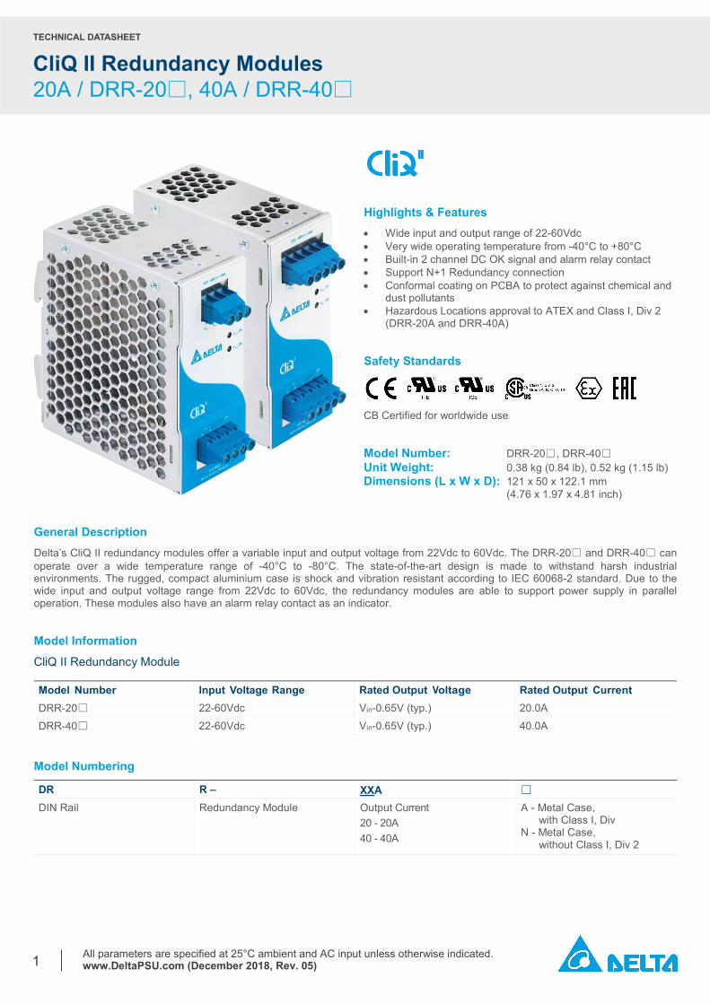
Highlights & Features • Wide input and output range of 22-60Vdc • Very wide operating temperature from -40°C to +80°C • Built-in 2 channel DC OK signal and alarm relay contact • Support N+1 Redundancy connection • Conformal coating on PCBA to protect against chemical and
dust pollutants • Hazardous Locations approval to ATEX and Class I, Div 2
(DRR-20A and DRR-40A)
Safety Standards
CB Certified for worldwide use
Model Number: DRR-20☐, DRR-40☐ Unit Weight: 0.38 kg (0.84 lb), 0.52 kg (1.15 lb) Dimensions (L x W x D): 121 x 50 x 122.1 mm (4.76 x 1.97 x 4.81 inch)
General Description Delta’s CliQ II redundancy modules offer a variable input and output voltage from 22Vdc to 60Vdc. The DRR-20☐ and DRR-40☐ can operate over a wide temperature range of -40°C to -80°C. The state-of-the-art design is made to withstand harsh industrial environments. The rugged, compact aluminium case is shock and vibration resistant according to IEC 60068-2 standard. Due to the wide input and output voltage range from 22Vdc to 60Vdc, the redundancy modules are able to support power supply in parallel operation. These modules also have an alarm relay contact as an indicator. Model Information CliQ II Redundancy Module Model Number Input Voltage Range Rated Output Voltage Rated Output Current DRR-20☐ 22-60Vdc Vin-0.65V (typ.) 20.0A DRR-40☐ 22-60Vdc Vin-0.65V (typ.) 40.0A
Model Numbering
DR R – XXA □ DIN Rail Redundancy Module Output Current
20 - 20A 40 - 40A
A - Metal Case, with Class I, Div N - Metal Case, without Class I, Div 2
TECHNICAL DATASHEET
CliQ II Redundancy Modules 20A / DRR-20□, 40A / DRR-40□
All parameters are specified at 25°C ambient and AC input unless otherwise indicated. www.DeltaPSU.com (December 2018, Rev. 05)
2
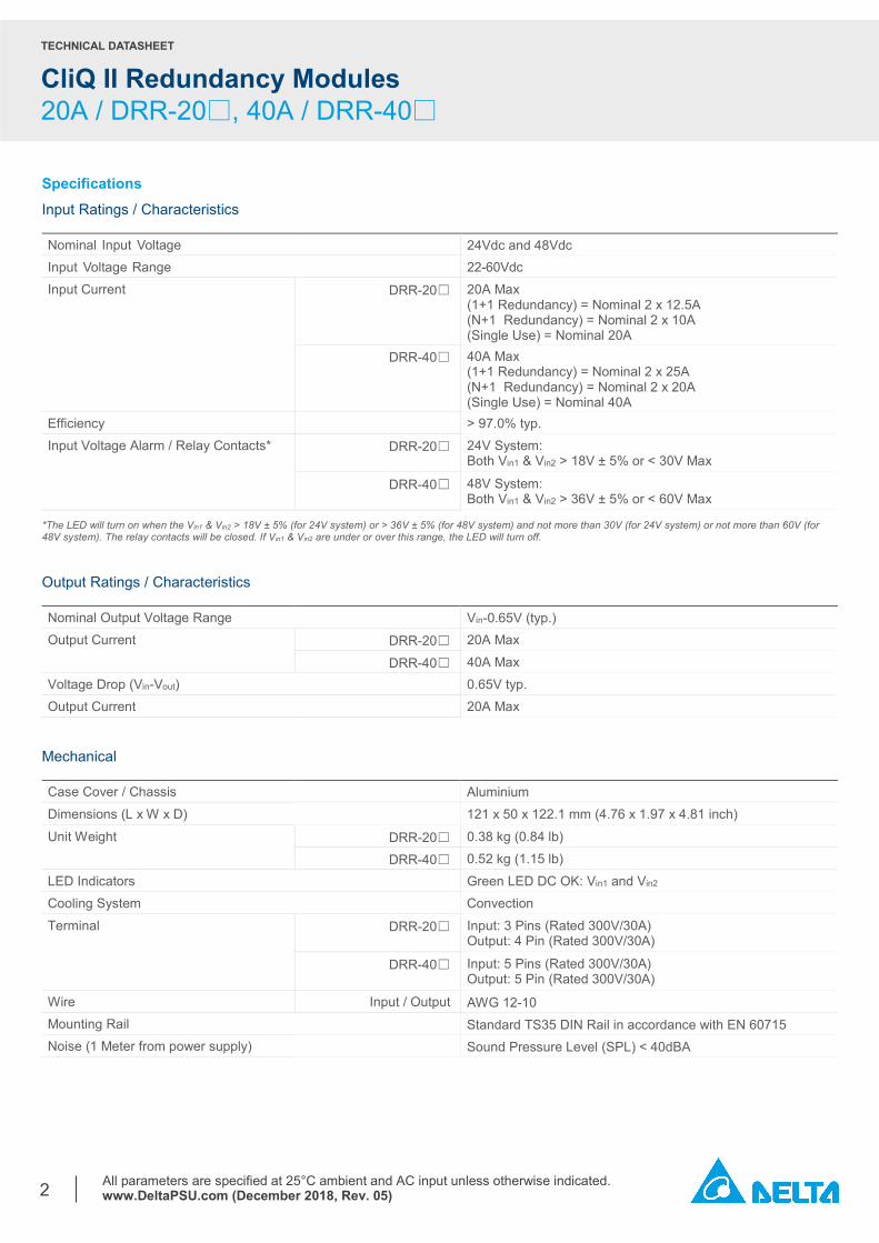
Specifications Input Ratings / Characteristics Nominal Input Voltage 24Vdc and 48Vdc Input Voltage Range 22-60Vdc Input Current DRR-20☐ 20A Max
(1+1 Redundancy) = Nominal 2 x 12.5A (N+1 Redundancy) = Nominal 2 x 10A (Single Use) = Nominal 20A
DRR-40☐ 40A Max (1+1 Redundancy) = Nominal 2 x 25A (N+1 Redundancy) = Nominal 2 x 20A (Single Use) = Nominal 40A
Efficiency > 97.0% typ. Input Voltage Alarm / Relay Contacts* DRR-20☐ 24V System:
Both Vin1 & Vin2 > 18V ± 5% or < 30V Max
DRR-40☐ 48V System: Both Vin1 & Vin2 > 36V ± 5% or < 60V Max
*The LED will turn on when the Vin1 & Vin2 > 18V ± 5% (for 24V system) or > 36V ± 5% (for 48V system) and not more than 30V (for 24V system) or not more than 60V (for 48V system). The relay contacts will be closed. If Vin1 & Vin2 are under or over this range, the LED will turn off. Output Ratings / Characteristics Nominal Output Voltage Range Vin-0.65V (typ.) Output Current DRR-20☐ 20A Max DRR-40☐ 40A Max Voltage Drop (Vin-Vout) 0.65V typ. Output Current 20A Max
Mechanical Case Cover / Chassis Aluminium Dimensions (L x W x D) 121 x 50 x 122.1 mm (4.76 x 1.97 x 4.81 inch) Unit Weight DRR-20☐ 0.38 kg (0.84 lb) DRR-40☐ 0.52 kg (1.15 lb) LED Indicators Green LED DC OK: Vin1 and Vin2 Cooling System Convection Terminal DRR-20☐ Input: 3 Pins (Rated 300V/30A)
Output: 4 Pin (Rated 300V/30A)
DRR-40☐ Input: 5 Pins (Rated 300V/30A) Output: 5 Pin (Rated 300V/30A)
Wire Input / Output AWG 12-10 Mounting Rail Standard TS35 DIN Rail in accordance with EN 60715 Noise (1 Meter from power supply) Sound Pressure Level (SPL) < 40dBA
TECHNICAL DATASHEET
CliQ II Redundancy Modules 20A / DRR-20□, 40A / DRR-40□
All parameters are specified at 25°C ambient and AC input unless otherwise indicated. www.DeltaPSU.com (December 2018, Rev. 05)
3
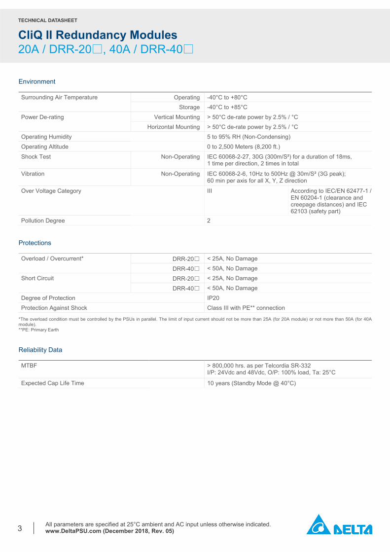
Environment Surrounding Air Temperature
Operating -40°C to +80°C Storage -40°C to +85°C Power De-rating Vertical Mounting > 50°C de-rate power by 2.5% / °C Horizontal Mounting > 50°C de-rate power by 2.5% / °C Operating Humidity 5 to 95% RH (Non-Condensing) Operating Altitude 0 to 2,500 Meters (8,200 ft.) Shock Test Non-Operating IEC 60068-2-27, 30G (300m/S²) for a duration of 18ms,
1 time per direction, 2 times in total
Vibration Non-Operating IEC 60068-2-6, 10Hz to 500Hz @ 30m/S² (3G peak); 60 min per axis for all X, Y, Z direction
Over Voltage Category III According to IEC/EN 62477-1 / EN 60204-1 (clearance and creepage distances) and IEC 62103 (safety part)
Pollution Degree 2 Protections Overload / Overcurrent* DRR-20☐ < 25A, No Damage DRR-40☐ < 50A, No Damage Short Circuit DRR-20☐ < 25A, No Damage DRR-40☐ < 50A, No Damage Degree of Protection IP20 Protection Against Shock Class III with PE** connection
*The overload condition must be controlled by the PSUs in parallel. The limit of input current should not be more than 25A (for 20A module) or not more than 50A (for 40A module). **PE: Primary Earth Reliability Data MTBF > 800,000 hrs. as per Telcordia SR-332
I/P: 24Vdc and 48Vdc, O/P: 100% load, Ta: 25°C Expected Cap Life Time 10 years (Standby Mode @ 40°C)
TECHNICAL DATASHEET
CliQ II Redundancy Modules 20A / DRR-20□, 40A / DRR-40□
All parameters are specified at 25°C ambient and AC input unless otherwise indicated. www.DeltaPSU.com (December 2018, Rev. 05)
4
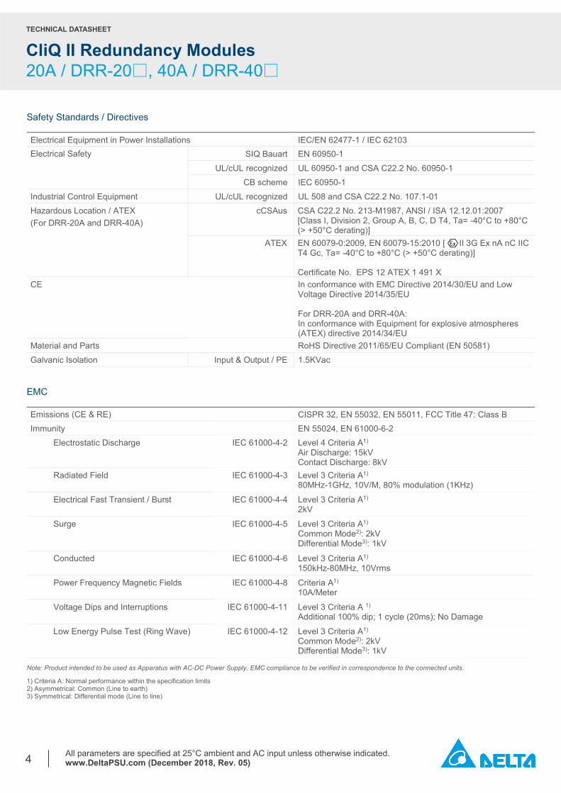
Safety Standards / Directives Electrical Equipment in Power Installations IEC/EN 62477-1 / IEC 62103 Electrical Safety SIQ Bauart
EN 60950-1
UL/cUL recognized
UL 60950-1 and CSA C22.2 No. 60950-1 CB scheme IEC 60950-1 Industrial Control Equipment UL/cUL recognized
UL 508 and CSA C22.2 No. 107.1-01 Hazardous Location / ATEX (For DRR-20A and DRR-40A)
cCSAus CSA C22.2 No. 213-M1987, ANSI / ISA 12.12.01:2007 [Class I, Division 2, Group A, B, C, D T4, Ta= -40°C to +80°C (> +50°C derating)]
ATEX EN 60079-0:2009, EN 60079-15:2010 [ II 3G Ex nA nC IIC T4 Gc, Ta= -40°C to +80°C (> +50°C derating)] Certificate No. EPS 12 ATEX 1 491 X
CE In conformance with EMC Directive 2014/30/EU and Low Voltage Directive 2014/35/EU For DRR-20A and DRR-40A: In conformance with Equipment for explosive atmospheres (ATEX) directive 2014/34/EU
Material and Parts RoHS Directive 2011/65/EU Compliant (EN 50581) Galvanic Isolation Input & Output / PE 1.5KVac
EMC Emissions (CE & RE) CISPR 32, EN 55032, EN 55011, FCC Title 47: Class B Immunity EN 55024, EN 61000-6-2
Electrostatic Discharge IEC 61000-4-2 Level 4 Criteria A1) Air Discharge: 15kV Contact Discharge: 8kV
Radiated Field IEC 61000-4-3 Level 3 Criteria A1) 80MHz-1GHz, 10V/M, 80% modulation (1KHz)
Electrical Fast Transient / Burst IEC 61000-4-4 Level 3 Criteria A1) 2kV
Surge IEC 61000-4-5 Level 3 Criteria A1) Common Mode2): 2kV Differential Mode3): 1kV
Conducted IEC 61000-4-6 Level 3 Criteria A1) 150kHz-80MHz, 10Vrms
Power Frequency Magnetic Fields IEC 61000-4-8 Criteria A1) 10A/Meter
Voltage Dips and Interruptions IEC 61000-4-11 Level 3 Criteria A 1)
Additional 100% dip; 1 cycle (20ms); No Damage
Low Energy Pulse Test (Ring Wave) IEC 61000-4-12 Level 3 Criteria A1) Common Mode2): 2kV Differential Mode3): 1kV
Note: Product intended to be used as Apparatus with AC-DC Power Supply, EMC compliance to be verified in correspondence to the connected units.
1) Criteria A: Normal performance within the specification limits 2) Asymmetrical: Common (Line to earth) 3) Symmetrical: Differential mode (Line to line)
TECHNICAL DATASHEET
CliQ II Redundancy Modules 20A / DRR-20□, 40A / DRR-40□
All parameters are specified at 25°C ambient and AC input unless otherwise indicated. www.DeltaPSU.com (December 2018, Rev. 05)
5
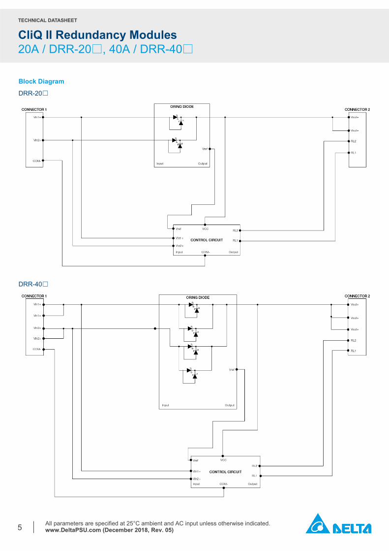
Block Diagram
DRR-20☐
DRR-40☐
TECHNICAL DATASHEET
CliQ II Redundancy Modules 20A / DRR-20□, 40A / DRR-40□
All parameters are specified at 25°C ambient and AC input unless otherwise indicated. www.DeltaPSU.com (December 2018, Rev. 05)
6
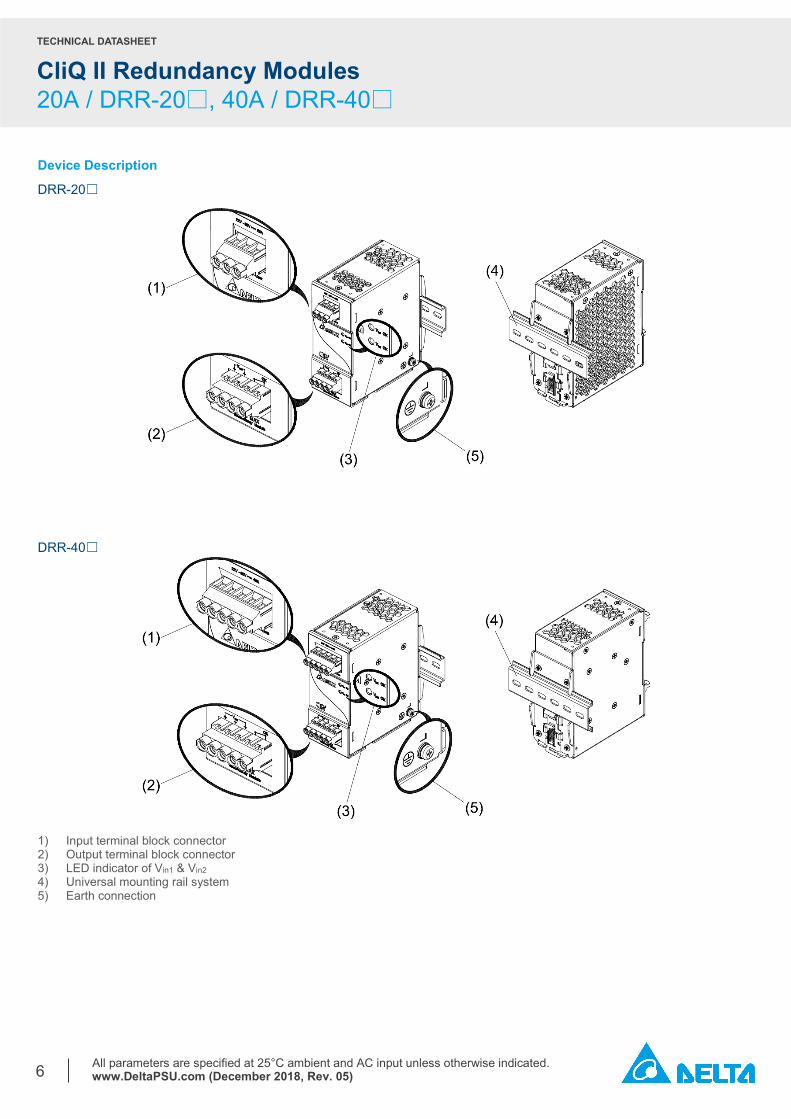
Device Description
DRR-20☐
DRR-40☐
1) Input terminal block connector 2) Output terminal block connector 3) LED indicator of Vin1 & Vin2 4) Universal mounting rail system 5) Earth connection
TECHNICAL DATASHEET
CliQ II Redundancy Modules 20A / DRR-20□, 40A / DRR-40□
All parameters are specified at 25°C ambient and AC input unless otherwise indicated. www.DeltaPSU.com (December 2018, Rev. 05)
7
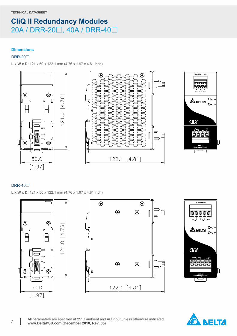
Dimensions
DRR-20☐
L x W x D: 121 x 50 x 122.1 mm (4.76 x 1.97 x 4.81 inch)
DRR-40☐
L x W x D: 121 x 50 x 122.1 mm (4.76 x 1.97 x 4.81 inch)
TECHNICAL DATASHEET
CliQ II Redundancy Modules 20A / DRR-20□, 40A / DRR-40□
All parameters are specified at 25°C ambient and AC input unless otherwise indicated. www.DeltaPSU.com (December 2018, Rev. 05)
8
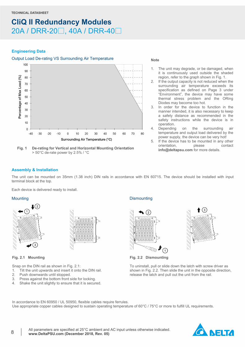
Engineering Data Output Load De-rating VS Surrounding Air Temperature
Assembly & Installation The unit can be mounted on 35mm (1.38 inch) DIN rails in accordance with EN 60715. The device should be installed with input terminal block at the top. Each device is delivered ready to install. Mounting
Note 1. The unit may degrade, or be damaged, when
it is continuously used outside the shaded region, refer to the graph shown in Fig. 1.
2. If the output capacity is not reduced when the surrounding air temperature exceeds its specification as defined on Page 3 under “Environment”, the device may have some thermal stress problem and the ORing Diodes may become too hot.
3. In order for the device to function in the manner intended, it is also necessary to keep a safety distance as recommended in the safety instructions while the device is in operation.
4. Depending on the surrounding air temperature and output load delivered by the power supply, the device can be very hot!
5. If the device has to be mounted in any other orientation, please contact [email protected] for more details. Fig. 1 De-rating for Vertical and Horizontal Mounting Orientation
> 50°C de-rate power by 2.5% / °C
Dismounting
Fig. 2.1 Mounting Snap on the DIN rail as shown in Fig. 2.1: 1. Tilt the unit upwards and insert it onto the DIN rail. 2. Push downwards until stopped. 3. Press against the bottom front side for locking. 4. Shake the unit slightly to ensure that it is secured.
Fig. 2.2 Dismounting To uninstall, pull or slide down the latch with screw driver as shown in Fig. 2.2. Then slide the unit in the opposite direction, release the latch and pull out the unit from the rail.
In accordance to EN 60950 / UL 50950, flexible cables require ferrules. Use appropriate copper cables designed to sustain operating temperature of 60°C / 75°C or more to fulfill UL requirements.
TECHNICAL DATASHEET
CliQ II Redundancy Modules 20A / DRR-20□, 40A / DRR-40□
All parameters are specified at 25°C ambient and AC input unless otherwise indicated. www.DeltaPSU.com (December 2018, Rev. 05)
9
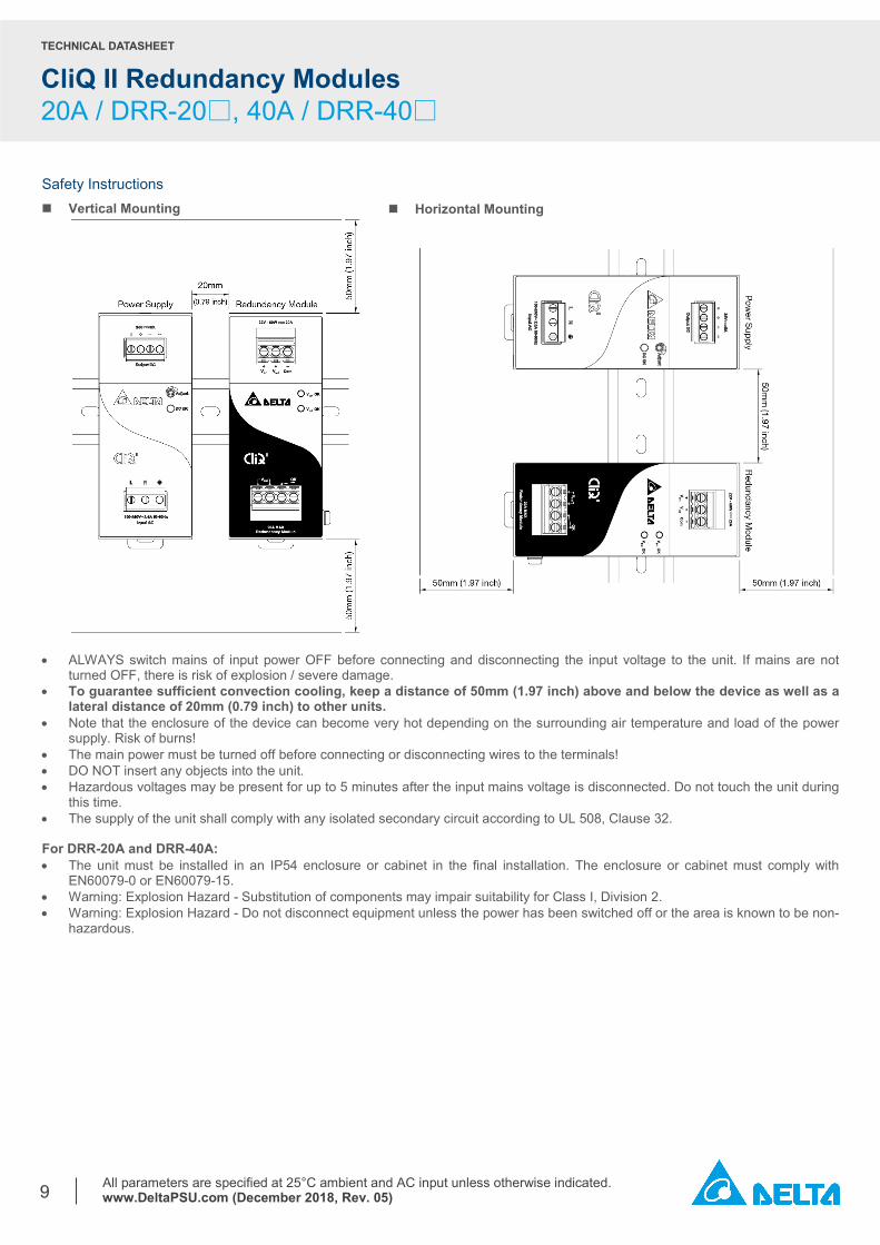
Safety Instructions Vertical Mounting
• ALWAYS switch mains of input power OFF before connecting and disconnecting the input voltage to the unit. If mains are not
turned OFF, there is risk of explosion / severe damage. • To guarantee sufficient convection cooling, keep a distance of 50mm (1.97 inch) above and below the device as well as a
lateral distance of 20mm (0.79 inch) to other units. • Note that the enclosure of the device can become very hot depending on the surrounding air temperature and load of the power
supply. Risk of burns! • The main power must be turned off before connecting or disconnecting wires to the terminals! • DO NOT insert any objects into the unit. • Hazardous voltages may be present for up to 5 minutes after the input mains voltage is disconnected. Do not touch the unit during
this time. • The supply of the unit shall comply with any isolated secondary circuit according to UL 508, Clause 32. For DRR-20A and DRR-40A: • The unit must be installed in an IP54 enclosure or cabinet in the final installation. The enclosure or cabinet must comply with
EN60079-0 or EN60079-15. • Warning: Explosion Hazard - Substitution of components may impair suitability for Class I, Division 2. • Warning: Explosion Hazard - Do not disconnect equipment unless the power has been switched off or the area is known to be non-
hazardous.
Horizontal Mounting
TECHNICAL DATASHEET
CliQ II Redundancy Modules 20A / DRR-20□, 40A / DRR-40□
All parameters are specified at 25°C ambient and AC input unless otherwise indicated. www.DeltaPSU.com (December 2018, Rev. 05)
10
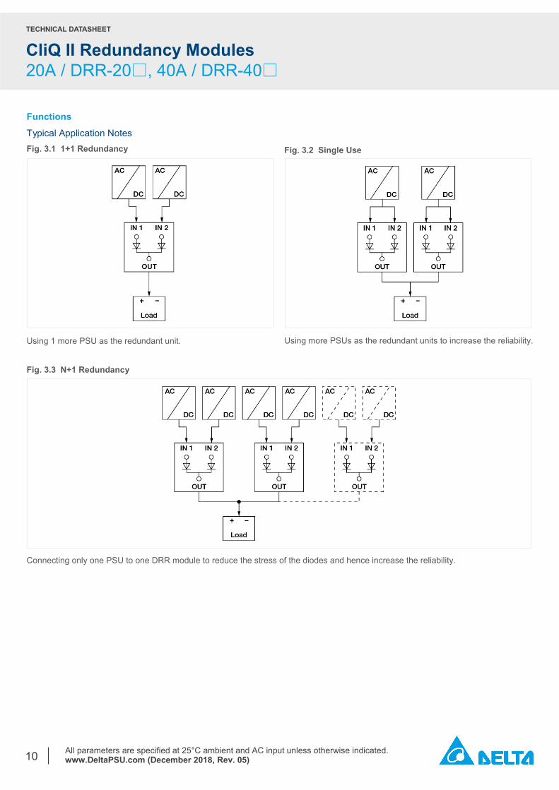
Functions Typical Application Notes Fig. 3.1 1+1 Redundancy
Using 1 more PSU as the redundant unit. Fig. 3.3 N+1 Redundancy
Connecting only one PSU to one DRR module to reduce the stress of the diodes and hence increase the reliability.
Fig. 3.2 Single Use
Using more PSUs as the redundant units to increase the reliability.
TECHNICAL DATASHEET
CliQ II Redundancy Modules 20A / DRR-20□, 40A / DRR-40□
All parameters are specified at 25°C ambient and AC input unless otherwise indicated. www.DeltaPSU.com (December 2018, Rev. 05)
11
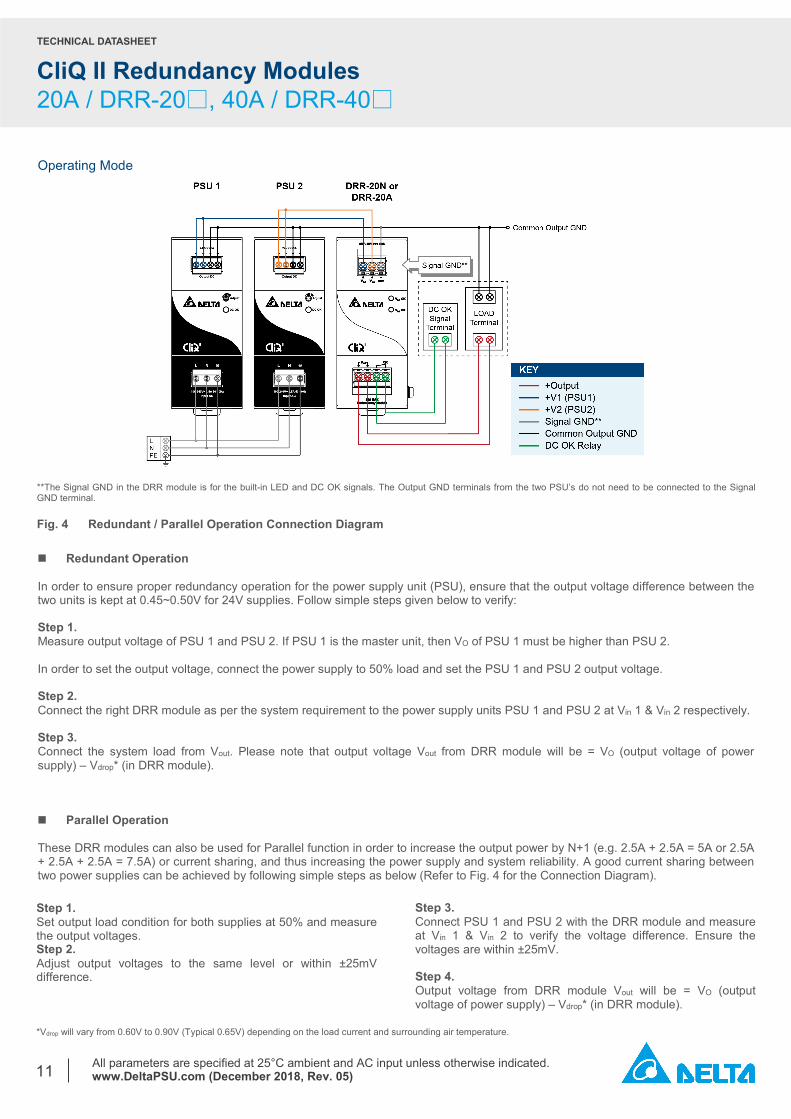
Operating Mode
Redundant Operation In order to ensure proper redundancy operation for the power supply unit (PSU), ensure that the output voltage difference between the two units is kept at 0.45~0.50V for 24V supplies. Follow simple steps given below to verify: Step 1. Measure output voltage of PSU 1 and PSU 2. If PSU 1 is the master unit, then VO of PSU 1 must be higher than PSU 2. In order to set the output voltage, connect the power supply to 50% load and set the PSU 1 and PSU 2 output voltage. Step 2. Connect the right DRR module as per the system requirement to the power supply units PSU 1 and PSU 2 at Vin 1 & Vin 2 respectively. Step 3. Connect the system load from Vout. Please note that output voltage Vout from DRR module will be = VO (output voltage of power supply) – Vdrop* (in DRR module). Parallel Operation These DRR modules can also be used for Parallel function in order to increase the output power by N+1 (e.g. 2.5A + 2.5A = 5A or 2.5A + 2.5A + 2.5A = 7.5A) or current sharing, and thus increasing the power supply and system reliability. A good current sharing between two power supplies can be achieved by following simple steps as below (Refer to Fig. 4 for the Connection Diagram). Step 1. Set output load condition for both supplies at 50% and measure the output voltages. Step 2. Adjust output voltages to the same level or within ±25mV difference.
Step 3. Connect PSU 1 and PSU 2 with the DRR module and measure at Vin 1 & Vin 2 to verify the voltage difference. Ensure the voltages are within ±25mV. Step 4. Output voltage from DRR module Vout will be = VO (output voltage of power supply) – Vdrop* (in DRR module).
*Vdrop will vary from 0.60V to 0.90V (Typical 0.65V) depending on the load current and surrounding air temperature.
**The Signal GND in the DRR module is for the built-in LED and DC OK signals. The Output GND terminals from the two PSU’s do not need to be connected to the Signal GND terminal. Fig. 4 Redundant / Parallel Operation Connection Diagram
TECHNICAL DATASHEET
CliQ II Redundancy Modules 20A / DRR-20□, 40A / DRR-40□
All parameters are specified at 25°C ambient and AC input unless otherwise indicated. www.DeltaPSU.com (December 2018, Rev. 05)
12
Others Delta RoHS Compliant
Restriction of the usage of hazardous substances
The European directive 2011/65/EU limits the maximum impurity level of homogeneous materials such as lead, mercury, cadmium, chrome, polybrominated flame retardants PBB and PBDE for the use in electrical and electronic equipment. RoHS is the abbreviation for “Restriction of the use of certain hazardous substances in electrical and electronic equipment”.
This product conforms to this standard. Conformal Coating
The Protective Coating Technology
Delta Electronics Group has designed the perfect dipping technique which penetrates everywhere including under device, and prevents leakage. The conformal coating dipping can be applied to PCBAs or circuit board. The coating preserves the performance of precision electronic primarily by preventing ionizable contaminants such as salt from reaching circuit nodes, where the material slumps around sharp edges. This can be a problem especially in highly conversing atmosphere.
Attention Delta provides all information in the datasheets on an “AS IS” basis and does not offer any kind of warranty through the information for using the product. In the event of any discrepancy between the information in the catalog and datasheets, the datasheets shall prevail (please refer to www.DeltaPSU.com for the latest datasheets information). Delta shall have no liability of indemnification for any claim or action arising from any error for the provided information in the datasheets. Customer shall take its responsibility for evaluation of using the product before placing an order with Delta.
Delta reserves the right to make changes to the information described in the datasheets without notice.
Mouser Electronics
Authorized Distributor
Click to View Pricing, Inventory, Delivery & Lifecycle Information: Delta Electronics:
DRR-20A DRR-20N


![Coupled Quench + Circuit modeling for the High Luminosity ... · CLIQ unit discharged over QA coils (1/2) 17 CLIQ discharge over QA coils (similar to [2,9-12]) •CLIQ unit electrically](https://static.fdocuments.net/doc/165x107/6042b9db4e0ed276762d6d35/coupled-quench-circuit-modeling-for-the-high-luminosity-cliq-unit-discharged.jpg)


