Clinker Storage Systems - AUMUND Fördertechnik · Clinker Storage Systems The AUMUND Group...
12
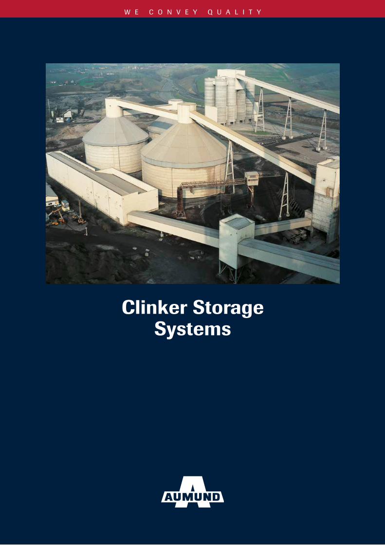
WE CONVEY QUALITY Clinker Storage Systems
Transcript of Clinker Storage Systems - AUMUND Fördertechnik · Clinker Storage Systems The AUMUND Group...
W E C O N V E Y Q U A L I T Y
Clinker Storage Systems

2
Circular storage hall 150,000 t
Circular storage hall 60,000 t
Circular storage hall 2 x 75,000 t
Content
2 Clinker Storage Systems
3 Circular Storage Hall without Central Column
4 Cylindrical Concrete or Steel Silos
6 Covered Stockpile with Central Column
7 Covered Stockpile with MOLEX®
8 Storage Hall with Earth Cone
9 Clinker Discharge Dust Suppression
10 Conversions and Refurbishments
19 After Sales Service
Clinker Storage Systems
The AUMUND Group Equipment for the Cement Industry is being applied world-wide in more than 10,000 plants.
Design, implementation and modernisation of clinker storage installations, customised as per requirement, achieve maximum customer benefit.
• Adaptedtothecustomer`sspecific requirements, all transport processes are constantly optimised based on innovations and the latest technical know-how.
• Combiningeconomicandecological aspects including future demands, balanced solutions are considered.
• Highsafetystandardsinall functions and under all conditions have been proven world-wide in technology, quality and reliability.
To receive an optimum overall conveying and storage layout, early involvement of AUMUND´s experienced layout engineers is recommended.

3
Circular storage hall 150,000 t
Circular storage hall without central column
Circular Storage Hall without Central Column
Circular storage hall with concrete cylinder and steel roof without central column
Preferred sizes
For total residue discharge, additional evacuation equipment is required.
Storing capacity in t with a bulk density of 1.5 t/m3.
D H h Storing capacity Dischargem m m t m3 rate %
15 14.1 34,900 23,250 8040 20 14.1 44,300 29,500 84
15 15.8 45,500 30,300 7645 20 15.8 57,400 38,800 80
25 15.8 69,300 46,200 8415 18.7 57,800 38,500 81
50 20 18.7 72,500 48,300 8425 18.7 87,200 58,200 8715 20.5 71,900 47,900 79
55 20 20.5 89,700 59,800 8225 20.5 108,000 71,700 8515 22.1 88,000 58,700 81
60 20 22.1 109,000 72,800 8425 22.1 130,000 86,900 87
15 25.0 106,000 70,700 8365 20 25.0 131,000 87,300 86
25 25.0 156,000 104,000 89
Storing capacity from 50,000 to 250,000 t
These circular storage halls consist of a pretensioned reinforced concrete cylinder with a diameter of 40 to 80 m and a height from 10 to 25 m. A cone-shaped roof structure is arranged above the concrete cylinder. The roof is a self-supporting steel frame covered with trapezoidal plates. Special sealing elements at the joints of the trapezoidal plates make the roof structure dust-tight. For compensation of thermal stresses, the roof structure is arranged on special sliding bearings which are installed in the upper edge of the concrete cylinder.
The roof structure supports the headhouse with the drive station of the pan conveyor and the filter systems for dedusting of the storage hall. The diameter and height of the headhouse are determined to suit the dimensions of these systems. For all circular storage hall diameters, the main dimensions of the roof structure and headhouse are standardised. The storing capacity of these circular storage halls ranges from 50,000 to 250,000 t. Larger capacities can also be realized. Due to the reduced system height and the large diameter, it is also possible to build these circular storage halls on soils with a low bearing capacity. A minimum of approx. 500 kN/m2 is required.
The material is discharged to two to four discharge tunnels, depending on the storage hall diameter. A discharge rate of approx. 85% is achieved.
During the loading process, the clinker segregates and forms cones according to the particle size. A homogenous clinker mixture is, however, an essential condition for the performance of cement mills. Therefore, it is recommended to systematically shift the silo discharge gates in order to blend the different particle sizes in the silo. In addition, regular shifting of the discharge openings ensures that the stored clinker level in the silo lowers uniformly, thus avoiding early discharge of fresh clinker.

4
Cylindrical Concrete or Steel Silos
These silos are made of reinforced concrete or prefabricated special steel. Due to the comparatively small basis, a high discharge rate of approx. 75 % is reached by means of one discharging conveyor only. This implies that the complete material stored in the silo can be extracted to a large extent by gravity discharge, without using mobile evacuation systems.
After several years, a total residue discharge of the silos should be effected, as the material particles Iying on the floor tend to consolidate and form a steep cone. Therefore, it is recommended to equip all silos with lockable entrance doors.
With clinker cooler problems, extremely high clinker tempe ratures exceeding 400 °C must be expected. For these high temperatures, clinker silos are preferably made of steel; otherwise the choice of steel or concrete depends on econo mical aspects. In certain regions steel plate silos can be produced at more favourable prices.
In general, the storing capacity of these silos ranges from 30,000 to 60,000 t. The largest cylindrical concrete silo designed by AUMUND has a diameter of 45 m and offers a storing capacity of 80,000 t. In view of the chosen diameter, the roof had to be designed as a self-supporting
steel framed structure with trapezoidal cladding – a design standard which is also applied for the large circular storage halls without a central column.
For automatic silo operation, a reliable level control system is of primary importance. A proven solution is the combination of an electro-mechanical silo pilot system to measure the material level in the silo. Several rope probes monitor the maximum filling level and several rod probes arranged in the area of the loading chute activate the emergency shutdown of the conveyor lines.
2 x 60,000 t silo
Storing capacity from 30,000 to 60,000 t

5
80,000 t silo with steel roof
Silo group for different clinker types
Steel silos, 30,000 t each
Clinker silos in series
D H h Storing capacity Dischargem m m approx. t m3 rate %
15.00 18.20 5.10 5,000 3,330 7817.50 19.80 5.90 7,500 5,000 7720.00 20.00 6.80 10,000 6,660 7422.50 23.60 7.60 15,000 10,000 7525.00 25.30 8.40 20,000 13,330 7527.50 26.00 9.30 25,000 16,660 7328.75 28.60 9.70 30,000 20,000 7430.00 30.60 10.10 35,000 23,330 7531.50 31.70 10.60 40,000 26,660 7533.00 32.40 11.10 45,000 30,000 7434.00 33.90 11.50 50,000 33,330 7535.00 35.20 11.80 55,000 36,660 7536.00 36.30 12.10 60,000 40,000 75
Cylindrical silosmade of concreteor steel with onedischarge tunnel
Storing capacity in t with a bulk density of 1.5 t/m3.

6
Storing capacity from 50,000 to 190,000 t
The salient features of the covered stockpile with a central column are the low system height and the large diameter. The roof structure covers the material’s angle of repose and only a low, circular retaining wall is required.
The central column is provided with slot-shaped outlet openings (stockpile) and supports the simple roof structure, consisting of the steel frame and the trapezoidal cladding. The platform above the central column is designed to receive the conveyor bridge with conveying equipment and the filter system.
A discharge rate of 40 % to 60 % is reached by installing one to three discharge tunnels. For total residue discharge, mobile evacuation systems will be required.
The standard storage diameters range from 70 to 110 m. Storing capacities of 50,000 to 190,000 t can thus be reached.
A special storing facility with a capacity of 230,000 t could be created by combining two storage halls. An essential condition for this project was the load distribution on a surface of 90 m x 126 m. Due to the bad soil with a relatively bad specific soil bearing capacity, special measures were required in order to avoid damage from differential settlement. The bridge structure was thus supported on special bearings and the roof fitted with a jacking system for repeated adjustment.
The two central columns with a diameter of 12 m provide a storing capacity of 4,500 t special clinker each. The storage hall is equipped with three discharge tunnels, ensuring a discharge rate of approx. 60 %.
The large roof surface of this storage hall offers another advantage: the cooling effect on the stored clinker.
Oval storage hall with internal silos
Covered stockpile with MOLEX®
Covered stockpile with three discharge tunnels
Circular storage hall with internal silo and earth cone
Covered Stockpile with Central Column
D H Storing capacitym m t m3
70 26.6 51,200 34,10080 30.0 75,300 50,20090 33.3 106,100 70,700100 36.7 144,200 96,100110 40.1 190,500 127,000
70 26.6 48,300 32,20080 30.0 71,700 47,80090 33.3 101,600 67,700100 36.7 138,800 92,500110 40.1 184,200 122,800
Discharge rate approx. 60 %. For total residue discharge, auxiliary equipment. Preferred sizes
Discharge rate 100 %
In case of irregular filling, a reduced output factor of 0.9 will have to be considered.Storing capacity in t, with a bulk density of 1.5 t/m3.
Covered stockpile with three discharge tunnels
Covered stockpilewith mole
7
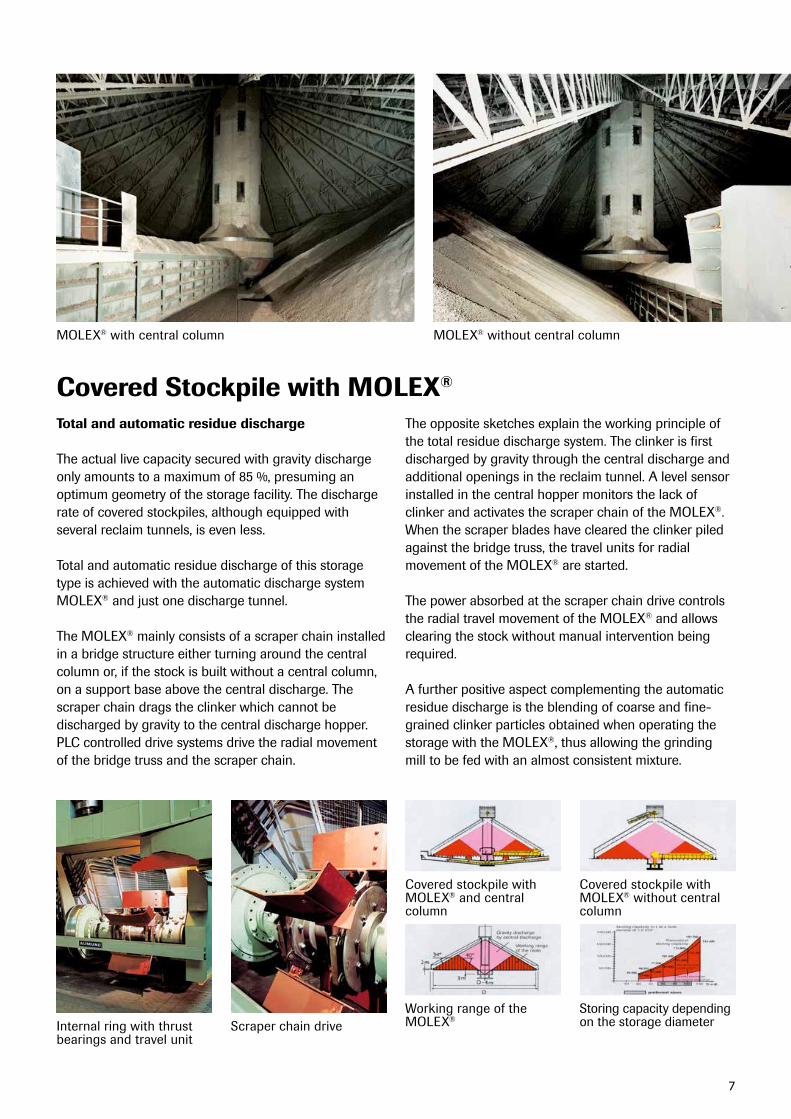
Total and automatic residue discharge
The actual live capacity secured with gravity discharge only amounts to a maximum of 85 %, presuming an optimum geometry of the storage facility. The discharge rate of covered stockpiles, although equipped with several reclaim tunnels, is even less.
Total and automatic residue discharge of this storage type is achieved with the automatic discharge system MOLEX® and just one discharge tunnel.
The MOLEX® mainly consists of a scraper chain installed in a bridge structure either turning around the central column or, if the stock is built without a central column, on a support base above the central discharge. The scraper chain drags the clinker which cannot be discharged by gravity to the central discharge hopper. PLC controlled drive systems drive the radial movement of the bridge truss and the scraper chain.
The opposite sketches explain the working principle of the total residue discharge system. The clinker is first discharged by gravity through the central discharge and additional openings in the reclaim tunnel. A level sensor installed in the central hopper monitors the lack of clinker and activates the scraper chain of the MOLEX®. When the scraper blades have cleared the clinker piled against the bridge truss, the travel units for radial movement of the MOLEX® are started.
The power absorbed at the scraper chain drive controls the radial travel movement of the MOLEX® and allows clearing the stock without manual intervention being required.
A further positive aspect complementing the automatic residue discharge is the blending of coarse and fine-grained clinker particles obtained when operating the storage with the MOLEX®, thus allowing the grinding mill to be fed with an almost consistent mixture.
MOLEX® with central column
Internal ring with thrust bearings and travel unit
Covered stockpile with MOLEX® and central column
Working range of the MOLEX®
Covered stockpile with MOLEX® without central column
Storing capacity depending on the storage diameterScraper chain drive
MOLEX® without central column
Covered Stockpile with MOLEX®

8
Circular storage hall with internal silo and earth cone
D H h T Storing capacitym m m m t m3
15 14.1 13.8 45,350 30,20040 20 14.1 13.8 54,750 36,500
15 15.8 15.9 60,400 40,30045 20 15.8 15.9 72,350 48,250
25 15.8 15.9 84,300 56,20015 18.7 18.0 78,300 52,200
50 20 18.7 18.0 93,050 62,05025 18.7 18.0 107,800 71,85015 20.5 20.1 99,300 66,200
55 20 20.5 20.1 117,100 78,10025 20.5 20.1 134,900 89,95015 22.1 22.2 123,500 82,350
60 20 22.1 22.2 144,700 96,50025 22.1 22.2 165,900 110,60015 25.0 24.3 151,250 100,850
65 20 25.0 24.3 176,150 117,40025 25.0 24.3 201,000 134,000
Circular storage hall with earth cone and without central column
Essential increase of storing capacity
The storing capacity of longitudinal and circular clinker storage halls can be essentially increased by the installation of an earth cone. In addition, the discharge rate is considerably improved by this measure. The earth cone is usually provided with an inclination of 40° to 45°. Untreated surfaces simply blasted out of the rock did not prove to be reliable in practice. Despite a low groundwater level, it has to be considered that surface water may penetrate into the earth cone through fissures and gaps. Therefore, the surface of the cone has to be covered with a concrete or steel shell. It is also recommended to install a drainage system in order to ensure that water accumulations can flow off.
For the roof and headhouse, a steel frame with trapezoidal cladding is preferred, as for circular storage halls without a central column.
Clinker discharge from the earth cone is effected through central discharge openings. For safety reasons, at least three silo discharge devices should be provided. These clinker storage halls can also be equipped with a central column, which is then used for storing special clinker. A rotating feed chute is required for feeding the central tower as well as for the symmetrical feeding of the main storage hall.
Clinker storage hall with earth cone
Storage Hall with Earth Cone
Circular storage hall with concrete cylinder, earth cone and steel roof without central column
Discharge rateapprox. 95 %
Preferred sizes
Storing capacity at a bulk weight of 1.5 t/m3.

9
Minimising dust generation without the use of dust filters
To reclaim the clinker, discharge systems which can be operated without the use of dust filters, are the preferred equipment for all kinds of clinker storage facilities.
The gravity discharge gate, combined with a pan conveyor reclaiming the clinker at low speed minimises dust generation.The conveying capacity is defined by
the adjustable discharge cross section and the pan conveyor speed. Frequency controlled drive units allow adapting the conveying capacity to operational requirements.
Deep-Drawn Pan Conveyors are the ideal equipment to combine with the gravity discharge system. With an optimum plant planning the Deep-Drawn Pan Conveyor allows for direct feeding of the mill hoppers in the grinding section.
Silo discharge by remote control – discharge capacity 750 t/h
Silo discharge according to the principle of gravity
Plant planning – Clinker silo with proportional addition of low-burnt clinker and truck loading
Filter and blower arrangement
Headhouse with conveyor drive station and filter
Clinker Discharge
Dust SuppressionIn order to avoid dust emissions from the clinker storage hall, negative pressure needs to be created in the feeding area. For this purpose, the filter system must be designed for an operating temperature of 100 °C. The air volume required depends on the storage diameter and the clinker temperature, which essentially influences the buoyant forces.
About 12,000 m3/h are required for small cylindrical silos and up to 60,000 m3/h or more for large-sized circular storage halls.
Vent hopper and compact filter systems proved to be a space sparing solution. A favourable load distribution is achieved if two filters are served by one blower.

10
Installation of new bucket strand
Pre-assembly of chain strands
Conversions and Refurbishments
• Upgradingofexistingplantcomponents• Targetingincreasedefficiency• Higheroutput• Improvedavailability
With our expert team of engineers planning selective modernisation measures, we pay special attention to the upgrading of existing plant components, targeting increased efficiency, higher output rates and improved availability.
Upgrading of your materials handling and storage equipment to state-of-the-art technology is achieved through a tailor-made refurbishment process under optimum utilisation of time and budget.
Most of the existing components are re-used in the refurbishment process to save cost.
Engineered conversions and refurbishments for increased efficiency and output are performed on AUMUND equipment as well as on the equipment of other manufacturers.

11
tHe AUMUnD GRoUP
GERMANY
AUMUND Fördertechnik GmbHSaalhoffer Str. 1747495 RheinbergPhone: +49 - 2843 - 72 0Fax: +49 - 2843 - 6 02 [email protected]
AUMUND Logistic GmbHSaalhoffer Str. 1747495 RheinbergPhone: +49 - 2843 - 72 0Fax: +49 - 2843 - 7 24 [email protected]
SCHADE Lagertechnik GmbHBruchstraße 145883 GelsenkirchenPhone: +49 - 209 - 50 31 60Fax: +49 - 209 - 50 31 62 [email protected]
GREAT BRITAIN
SAMSON Materials Handling Ltd.Gemini House Cambridgeshire BusinessPark,1Bartholomew`sWalkEly, Cambridgeshire CB7 4EAPhone: +44 - 1353 - 665 001Fax: +44 - 1353 - 666 [email protected]
INDIA
AUMUND Engineering Private Ltd.2nd Floor, Lakshmi Neela Rite Choice Chambers · 9, Bazulla Road, T. Nagar Chennai - 600 017Phone: +91 - 44 - 4393 63 00Fax: +91 - 44 - 2815 60 [email protected]
HONG KONG SAR
AUMUND Asia (H.K.) LimitedUnit 3B & 5, 30/F. 148 Electric Road North Point Hong KongPhone: +852 - 3695 - 43 33Fax: +852 - 3695 - 43 [email protected]
DUBAI U.A.E.
AUMUND Fördertechnik GmbHRepresentative OfficeP.O. Box 35291Dubai, UAEPhone: +971 - 4 - [email protected]
THE NETHERLANDSAUMUND Holding B.V.Wilhelminapark 405911 EE VenloPhone: +31 - 77 - 320 01 11Fax: +31 - 77 - 320 07 [email protected]
SWITZERLANDAUMUND AGArther Str. 36301 ZugPhone: +41 - 41 - 710 10 82Fax: +41 - 41 - 710 42 [email protected]
RUSSIAAUMUND Representative OfficeGerman-Russian House, Office 44ul. Malaja Pirogovskaja 5119435 Moscow / RussiaPhone: +7 - 495 - 287 90 02Fax: +7 - 495 - 287 90 [email protected]
SCHADE Representative OfficeGerman-Russian House, Office 44ul. Malaja Pirogovskaja 5119435 Moscow / RussiaPhone: +7 - 495 - 287 90 03Fax: +7 - 495 - 287 90 [email protected]
FRANCEAUMUND France S.A.R.L.43, rue de Trévise · F 75009 ParisPhone: +33 - 1 - 42 46 72 72Fax: +33 - 1 - 42 46 72 [email protected]
BRAZILAUMUND Ltda.Avenida Eng. Luis Carlos Berrini 716 - 4.andar - conj. 4104571-000 - São Paulo / SPPhone: +55 - 11 - 3059 0160Fax: +55 - 11 - 3059 [email protected]
USAAUMUND Corporation1701 Barrett Lakes BlvdBarrett Lakes Center ISuite 450Kennesaw, GA 30144Phone: +1 - 770 - 226 - 95 78Fax: +1 - 770 - 953 - 48 [email protected]
P.R. CHINAAUMUND Machinery Trading (Beijing) Co. Ltd.Rm. 7-8, 22-F, East Ocean CentreNo. 24 Jianguomenwai AvenueChaoyang DistrictBeijing 100004Phone: +86 - 10 - 65 15 58 13 / 14Fax: +86 - 10 - 65 15 58 [email protected]
After Sales ServiceCustomer Proximity around the WorldAt AUMUND, service does not end at the sale of the equipment. It’s the beginning of a long-term partnership. AUMUND offers you a full range of services – from commissioning to the delivery of quality spare and wear parts to customized preventive maintenance programs and equipment upgrading. The benefits for you: Maximum equipment efficiency at lower operating cost.
Commissioning and Field Service Today, presence “on the spot” is an absolute “must”. Therefore, our commissioning and service engineers operate from support centers on all continents to guarantee immediate and competent support.
Spare and Wear PartsA comprehensive range of genuine spare parts is available for our entire product range from stocks in Germany, Hong Kong, Brazil and the USA. Our product specialists provide assistance and respond instantly.
Retrofits & ModernisationAged and worn equipment? Capacity increase needed? Too high operating cost? AUMUND “just as new” retrofits are economical and tailor-made solutions for improving your existing equipment at reasonable cost.
Preventive MaintenanceKnowing beforehand that service will be needed allows you to schedule downtime and save money with timely repairs. Repairs or retrofits can be accurately anticipated allowing for the downtime to be at the most convenient times and at the lowest possible cost.

W E C O N V E Y Q U A L I T Y
AUMUND Headquarters in Rheinberg, Germany
AUMUND Foerdertechnik GmbH · Saalhoffer Str. 17 · 47495 Rheinberg (Germany) Tel.: + 49 (0) 28 43-720 · Fax: + 49 (0) 28 43-6 02 70 · [email protected]
www.aumund.com
Your partner for all requirements regarding material handling and storage.
We design, engineer, manufacture, erect and service reliable equipment.
Reputation and competence proven by more than10 000 installations in over 100 countries.
GB
Te
chni
cal d
ata
subj
ect t
o ch
ange
with
out n
otic
e A
-GB
-5/1
5 -M
A. ©
201
5 by
AU
MU
ND
Hol
ding
B.V
. All
right
s re
serv
ed.