CLIC drive beam accelerating (DBA) structure Rolf Wegner.
30
14-Oct-2009 CLIC DBA Rolf Wegner 1 CLIC drive beam accelerating (DBA) structure Rolf Wegner
-
Upload
tessa-chivers -
Category
Documents
-
view
221 -
download
1
Transcript of CLIC drive beam accelerating (DBA) structure Rolf Wegner.
14-Oct-2009 CLIC DBA Rolf Wegner 1
CLIC drive beam accelerating (DBA) structure
Rolf Wegner
14-Oct-2009 CLIC DBA Rolf Wegner 2
Outline
• CLIC drive beam complex, 3 GHz DBA structure
• design of 1 GHz DBA structure
• optimisations for efficiency and filling time
• damping and detuning
• summary

14-Oct-2009 CLIC DBA Rolf Wegner 3
CLIC RF power sourcefacc= 0.99952 GHz
Ipulse= 4.2 A
Vacc= 2.37 GV
Ppeak,RF ≈ 12 GW
Pavg,RF ≈ 90 MW
14-Oct-2009 CLIC DBA Rolf Wegner 4
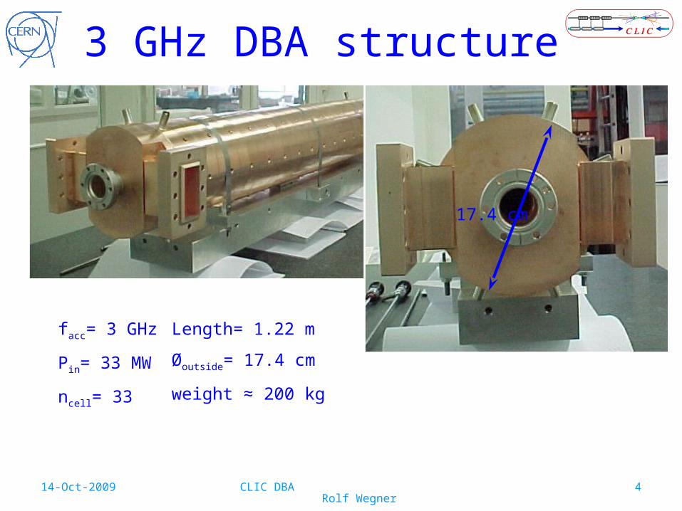
3 GHz DBA structure
facc= 3 GHz
Pin= 33 MW
ncell= 33
Length= 1.22 m
Øoutside= 17.4 cm
weight ≈ 200 kg
17.4 cm
14-Oct-2009 CLIC DBA Rolf Wegner 5
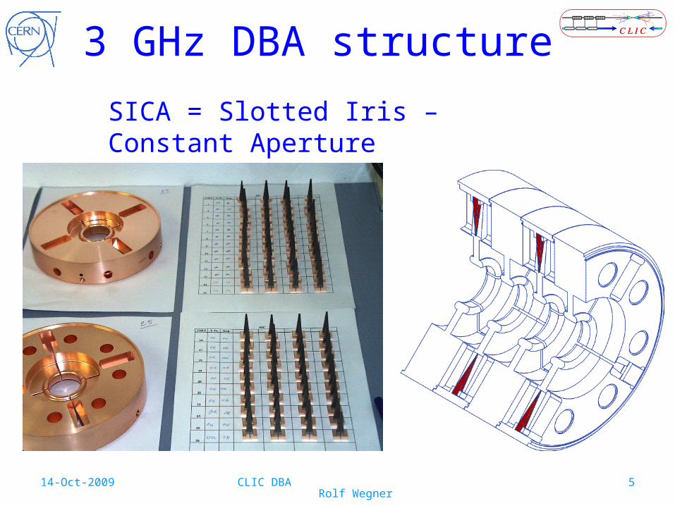
3 GHz DBA structure
SICA = Slotted Iris – Constant Aperture

14-Oct-2009 CLIC DBA Rolf Wegner 6
1 GHz DBA structure
• SICA principle• but no direct scaling possible
• 3 GHz: Ø= 17.5 cm, L= 1.2 m, weight= 200 kg1 GHz: Ø= 52.5 cm, L= 1.2 m, weight= 1800 kg
• klystron PRF ~ 10 to 15 MW(optimising klystron cost per MW and per operating hour and modulator cost)
• noise, phase error reduction if tfill= 240…250 ns(combination scheme => multiplication of phase noise,tDL≈ 245 ns, tCR I ≈ 2*245 ns, tCR II ≈ 6*245 ns)

14-Oct-2009 CLIC DBA Rolf Wegner 7
basic cell geometry
Rb
gapb
Lb
gapa
La
RBP
Ra
110
60
11
18R 6
R 6
R 9
R 9
99.979
3 basic cells
typical dimensions

14-Oct-2009 CLIC DBA Rolf Wegner 8
simulations of basic cells
variations:RBP
gap <=> vgr/c
tuning Ra => f0= 0.99952 GHz
0.5 1 1.5 2 2.5 3 3.5 4 4.5 50.5
1
1.5
2
2.5x 10
4
vgr/c [%]
Q0
RBP
=31.0mm
RBP
=35.0mm
RBP
=39.0mm
RBP
=43.0mm
RBP
=47.0mm
RBP
=51.0mm
0.5 1 1.5 2 2.5 3 3.5 4 4.5 50
50
100
150
200
vgr/c [%]
R/Q
0 [O
hm]
R/Q0=R0*T2/Q0
R0/Q0
0.5 1 1.5 2 2.5 3 3.5 4 4.5 50
2
4
6
vgr/c [%]
R [
MO
hm]
R0T2
R0
vgr/c range:min ~ 0.4% to 0.5%
14-Oct-2009 CLIC DBA Rolf Wegner 9
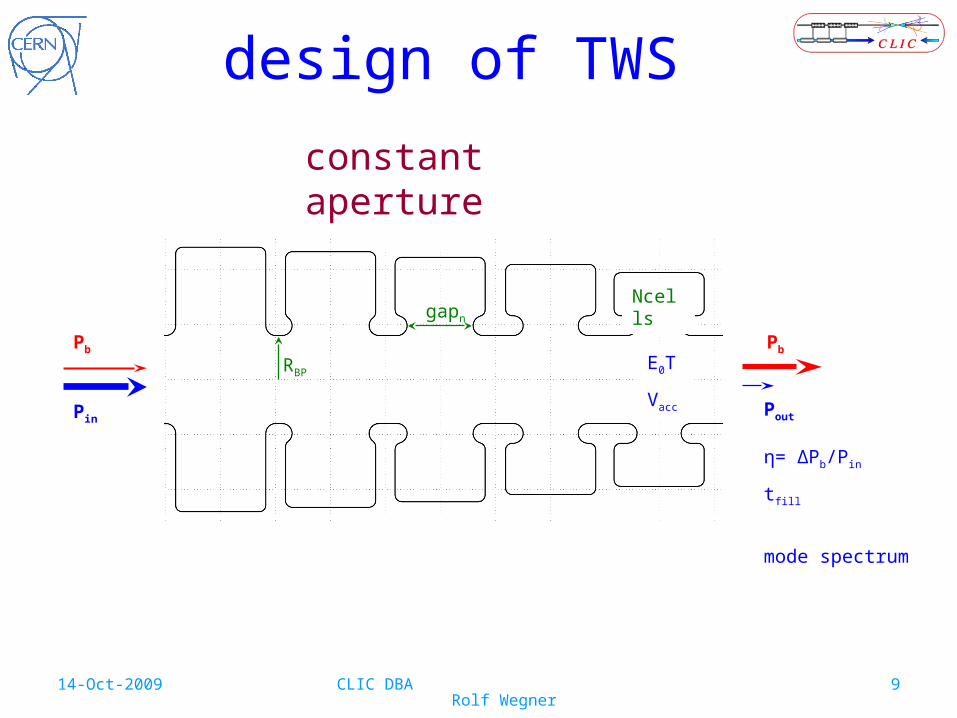
design of TWS
gapn
RBPE0T
Vacc
Ncells
PoutPin
Pb Pb
constant aperture
η= ΔPb/Pin
tfill
mode spectrum

14-Oct-2009 CLIC DBA Rolf Wegner 10
design of TWS
example:
Pin= 10 MWIb= 4.21 ANcells= 10RBP= 39 mm
vgr/c (gap) constη= 97.7%tfilling= 239.9 ns
vgr/c lin. distributionη= 98.0%tfilling= 252.7 ns
9 9.2 9.4 9.6 9.8 10 10.2 10.4 10.6 10.8 110
1
2
3
cell no
1-et
a(n)
[%
]
f0= 1.000 GHz, bore Radius= 39.00 mm, mean(Pin)= 10.00 MW
i_vgr=1
i_vgr=2
9 9.2 9.4 9.6 9.8 10 10.2 10.4 10.6 10.8 11230
240
250
260
cell no
t_fil
l [ns
]
1 2 3 4 5 6 7 8 9 100
1
2
3
cell no
vgr/
c0 [
%]
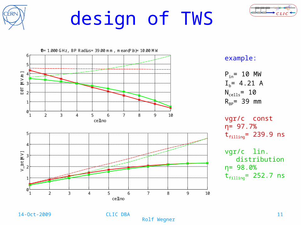
14-Oct-2009 CLIC DBA Rolf Wegner 11
design of TWS
example:
Pin= 10 MWIb= 4.21 ANcells= 10RBP= 39 mm
vgr/c constη= 97.7%tfilling= 239.9 ns
vgr/c lin. distributionη= 98.0%tfilling= 252.7 ns
1 2 3 4 5 6 7 8 9 100
1
2
3
4
5
6
cell no
E0T
[M
V/m
]
f0= 1.000 GHz, BP Radius= 39.00 mm, mean(Pin)= 10.00 MW
i_vgr=1
i_vgr=2
1 2 3 4 5 6 7 8 9 100
1
2
3
4
5
cell no
V_i
nt [
MV
]

14-Oct-2009 CLIC DBA Rolf Wegner 12
design of TWS
1 2 3 4 5 6 7 8 9 100
2
4
6
8
10
cell no
P_i
n [M
W]
f0= 1.000 GHz, BP Radius= 39.00 mm, mean(Pin)= 10.00 MW
i_vgr=1
i_vgr=2
1 2 3 4 5 6 7 8 9 100
50
100
150
cell no
P_d
per
cel
l [kW
]
example:
Pin= 10 MWIb= 4.21 ANcells= 10RBP= 39 mm
vgr/c constη= 97.7%tfilling= 239.9 ns
vgr/c lin. distributionη= 98.0%tfilling= 252.7 ns
14-Oct-2009 CLIC DBA Rolf Wegner 13
9 9.2 9.4 9.6 9.8 10 10.2 10.4 10.6 10.8 110
1
2
3
cell no
1-et
a(n)
[%
]
f0= 1.000 GHz, BP Radius= 39.00 mm, mean(Pin)= 10.00 MW
9 9.2 9.4 9.6 9.8 10 10.2 10.4 10.6 10.8 110
500
1000
cell no
t_fil
l [ns
]
1 2 3 4 5 6 7 8 9 100
1
2
3
cell no
vgr/
c0 [
%]
9 9.2 9.4 9.6 9.8 10 10.2 10.4 10.6 10.8 110
1
2
3
cell no
1-et
a(n)
[%
]
f0= 1.000 GHz, BP Radius= 39.00 mm, mean(Pin)= 10.00 MW
9 9.2 9.4 9.6 9.8 10 10.2 10.4 10.6 10.8 110
200
400
cell no
t_fil
l [ns
]
1 2 3 4 5 6 7 8 9 100
1
2
3
cell no
vgr/
c0 [
%]
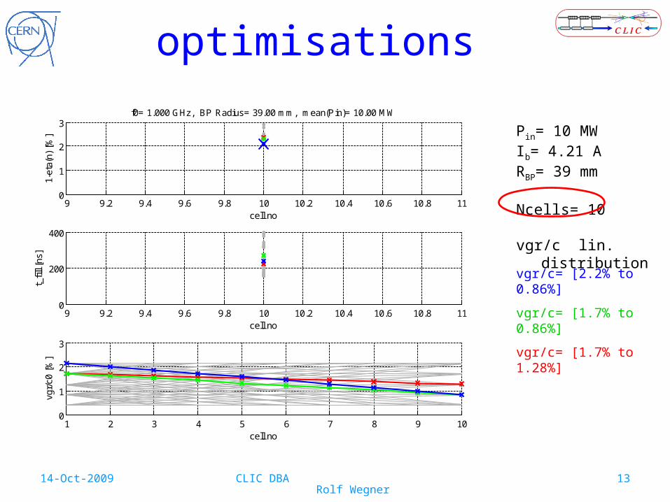
optimisations
Pin= 10 MWIb= 4.21 ARBP= 39 mm
Ncells= 10
vgr/c lin. distribution
vgr/c= [2.2% to 0.86%]
vgr/c= [1.7% to 0.86%]
vgr/c= [1.7% to 1.28%]

14-Oct-2009 CLIC DBA Rolf Wegner 14
optimisations - efficiency
Pin= 10 MWIb= 4.21 ARBP= 39 mm
Ncells= 4 .. 16
vgr/c lin. distributionoptimised for
efficiency
4 6 8 10 12 14 160
2
4
6
cell no
1-et
a(n)
[%
]
f0= 1.000 GHz, BP Radius= 39.00 mm, mean(Pin)= 10.00 MW
i_vgr=91i_vgr=167
i_vgr=169
i_vgr=187
i_vgr=221i_vgr=240
i_vgr=210
i_vgr=165i_vgr=135
i_vgr=15
i_vgr=15
i_vgr=15i_vgr=15
4 6 8 10 12 14 16200
300
400
500
cell no
t_fil
l [ns
]
2 4 6 8 10 12 14 160
1
2
3
cell no
vgr/
c0 [
%]
efficiency

14-Oct-2009 CLIC DBA Rolf Wegner 15
• noise damping => D, tfill
combined optimisations
DBA structure tasks:
• acceleration => ηRF
Drive Beam Accelerator
Delay Loop 2gap creation, pulse
compression & frequency
multiplication
1st Combiner Ring 3
2nd Combiner Ring 4
pulse compression & frequency multiplication
tDL~ 245 ns
appropriate tfill => noise suppression at f = 1/tDL

14-Oct-2009 CLIC DBA Rolf Wegner 16
tfill [ns]
da
mp
ing
fa
cto
r D
245 nsD ≈ 1/18
368 nsD ≈ 1/4
124 nsD ≈ 1/4
combined optimisations
245 ± 8.5 ns D ≈ 1/17
t0= 245 ns
Δt= 8.5 ns
α= 2%
combination for optimisation
C(ηRF,tfill)= f1(ηRF) + f2(tfill)
DBA structure tasks:
• acceleration => ηRF
• noise damping => D, tfill
f1(ηRF)= 1- ηRF
f2(tfill)= α ((tfill-t0)/Δt)2
appropriate tfill => noise suppression at f = 1/tDL
14-Oct-2009 CLIC DBA Rolf Wegner 17
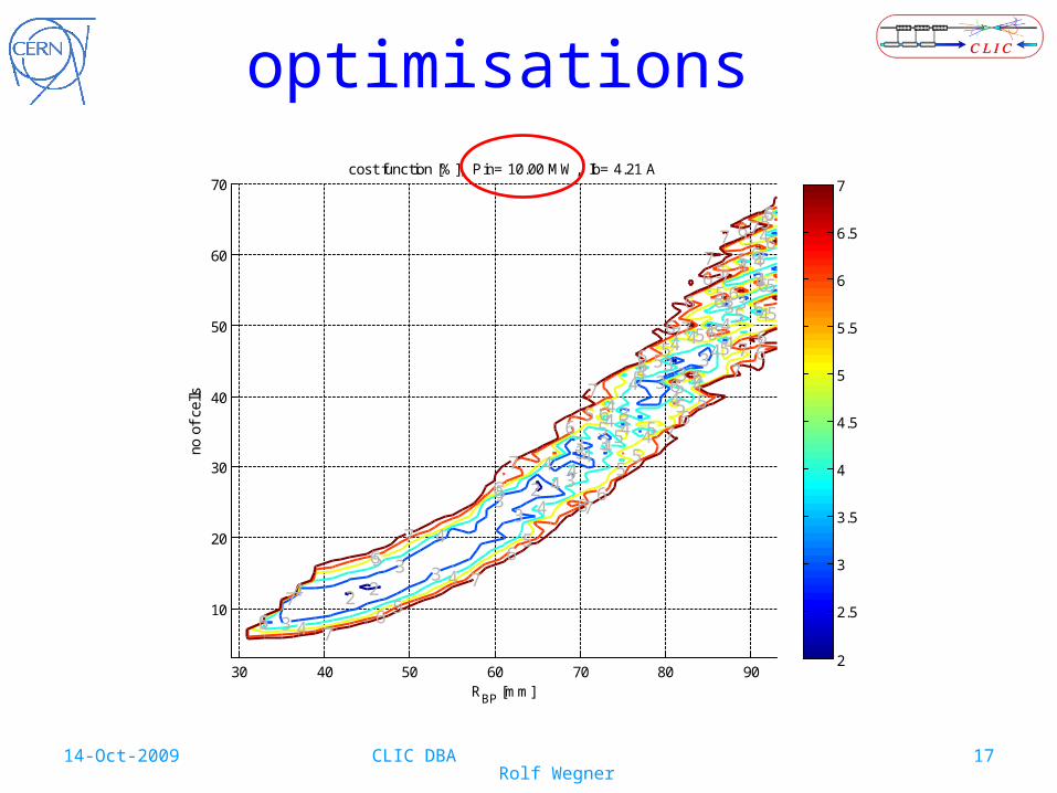
optimisations
30 40 50 60 70 80 90
10
20
30
40
50
60
70
2 2
2
33
3
3
3
33
3
3
33 33
3
333
3
444
44
4
4
4
44
4
4
4
44
4
44
44
4
4
4
4444
44
4
55
5
5
5
5
5
5
5
55
5
5
5
5
5
5
5
55
5
55
5
5
5
5
55
5
6
6
6
6
6
6
6
6 6
6
6
6
6
6
6
6
6
6
66
6
6
6
6
6
6
6
6
7
7
7
7
7
7
7
7
7
7
7
7
77
77
7
7
RBP
[mm]
no o
f ce
lls
cost function [%], Pin= 10.00 MW, Ib= 4.21 A
2
2.5
3
3.5
4
4.5
5
5.5
6
6.5
7

14-Oct-2009 CLIC DBA Rolf Wegner 18
optimisations
95
95
95
95
95
95
95
95
95
9595
96
96
96
96
96
96
96
96
9696
969696
9797
9797
97
97
97
97
97
9797
97
97
97
97.5
97.5
97.5
97.5
97.5
97.5
97.597.5
97.5
98
98
9898
98
98
98
98
RBP
[mm]
no o
f ce
lls
efficiency [%], Pin= 10.00 MW, Ib= 4.21 A
30 40 50 60 70 80 90
10
20
30
40
50
60
70
235
235
235
235
235
235
235
235
235
235
235
245
245
245
245
245245
245245
245245
245
245
245
245
245
245245
245
245 245
245
245
245
245
245
245
245
245
245245
245
245245
245
245
245
245245
245
245
245
245245
245
245
245
245
245
245
245245
245
245
245
245
245
245245245
245
245245
245245
245245
245
245
245
255
255
255
255
265
265
265
265
275
275
275
RBP
[mm]
no o
f ce
lls
filling time [ns], Pin= 10.00 MW, Ib= 4.21 A
30 40 50 60 70 80 90
10
20
30
40
50
60
70

14-Oct-2009 CLIC DBA Rolf Wegner 19
optimisations
5 10 15 20 25 30 35 400
5
10
15Pin= 10.00 MW, Ib= 4.21 A
cell no
vgr/
c0 [
%]
N= 7, RB=33.0mm
N=10, RB=39.0mmN=13, RB=45.0mm
N=16, RB=53.0mm
N=19, RB=55.0mm
N=22, RB=59.0mmN=25, RB=63.0mm
N=28, RB=65.0mm
N=31, RB=71.0mm
N=34, RB=73.0mmN=37, RB=77.0mm
N=40, RB=79.0mm
235 240 245 250 2550
1
2
3
4
5
filling time [ns]
1-et
a [%
]

14-Oct-2009 CLIC DBA Rolf Wegner 20
optimisations
ηRF ≥ 97.5 %
|tfill – 245 ns| ≤ 5 ns
0 10 20 30 40 50 60 70 80 900
10
20
30
40
50
60
70
RB [mm]
cell
no
no of cells <-> BP radius, eta >= 97.5%, |tfill-t0| <= 5.00 ns, Ib= 4.21 A
Pin= 5.00 MWPin= 10.00 MW
Pin= 15.00 MW
Pin= 20.00 MW
Pin= 30.00 MWPin= 40.00 MW

14-Oct-2009 CLIC DBA Rolf Wegner 21
damping and detuningreduction of transverse wakefields by damping and detuning
Alexej Grudiev’s suggestion:dampers in web (~18 mm tick)
acc. mode Q0= 2.2 10∙ 4, Qext= 3.7 10∙ 7
distorted, 0.1° <=> 0.1 mm @ nose Qext= 1.5 10∙ 6 Pext,peak= 110 W, Pext,avg= 0.83 W (Pcell,peak= 30 kW, d.c. 0.75%)
Ø≈ 25 cm

14-Oct-2009 CLIC DBA Rolf Wegner 22
damping and detuningreduction of transverse wakefields by damping and detuning
0 20 40 60 80 100 120 140 160 180
1
1.5
2
2.5
3
3.5
phase advance per cell [°]
freq
uenc
y [G
Hz]
Monopole Modes
cell 01
cell 07
cell 11
beam may excite multiples of 0.5 GHz
(only every other bucket filled)
11 cell structureRBP= 41 mm

14-Oct-2009 CLIC DBA Rolf Wegner 23
0 20 40 60 80 100 120 140 160 180
1
1.5
2
2.5
3
3.5
phase advance per cell [°]
freq
uenc
y [G
Hz]
Dipole Modes
cell 01
cell 07
cell 11
damping and detuningreduction of transverse wakefields by damping and detuning
Q_11= 28Q_07= 34Q_01= 33
Q_11= 31

14-Oct-2009 CLIC DBA Rolf Wegner 24
next steps
• wakefield calculation• optimisation of damping
• RF design• beam dynamics• mechanical design
=> iterations
14-Oct-2009 CLIC DBA Rolf Wegner 25
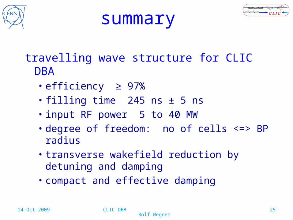
summary
travelling wave structure for CLIC DBA• efficiency ≥ 97%• filling time 245 ns ± 5 ns• input RF power 5 to 40 MW • degree of freedom: no of cells <=> BP radius• transverse wakefield reduction by detuning and
damping• compact and effective damping

14-Oct-2009 CLIC DBA Rolf Wegner 26
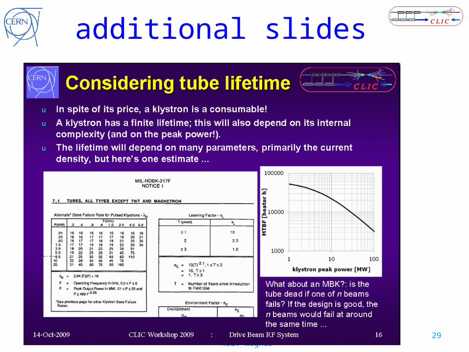
additional slides

14-Oct-2009 CLIC DBA Rolf Wegner 27
additional slides

14-Oct-2009 CLIC DBA Rolf Wegner 28
additional slides
14-Oct-2009 CLIC DBA Rolf Wegner 29
additional slides

14-Oct-2009 CLIC DBA Rolf Wegner 30
additional slides