CLEVER CONTROL - Version: V63 CLEVER CONTROL CHARACTERISTICS CLEVER, the new advanced total control,...
58
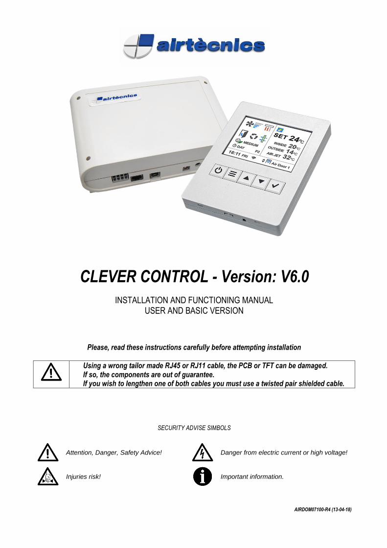
CLEVER CONTROL - Version: V6.0 INSTALLATION AND FUNCTIONING MANUAL USER AND BASIC VERSION Please, read these instructions carefully before attempting installation Using a wrong tailor made RJ45 or RJ11 cable, the PCB or TFT can be damaged. If so, the components are out of guarantee. If you wish to lengthen one of both cables you must use a twisted pair shielded cable. SECURITY ADVISE SIMBOLS Attention, Danger, Safety Advice! Danger from electric current or high voltage! Injuries risk! Important information. AIRDOM07100-R4 (13-04-18)
Transcript of CLEVER CONTROL - Version: V63 CLEVER CONTROL CHARACTERISTICS CLEVER, the new advanced total control,...
CLEVER CONTROL - Version: V6.0
INSTALLATION AND FUNCTIONING MANUAL USER AND BASIC VERSION
Please, read these instructions carefully before attempting installation
Using a wrong tailor made RJ45 or RJ11 cable, the PCB or TFT can be damaged. If so, the components are out of guarantee. If you wish to lengthen one of both cables you must use a twisted pair shielded cable.
SECURITY ADVISE SIMBOLS
Attention, Danger, Safety Advice!
Danger from electric current or high voltage!
Injuries risk!
Important information.
AIRDOM07100-R4 (13-04-18)

2
INDEX
CLEVER CONTROL CHARACTERISTICS ......................................................................................................... 3 CLEVER KIT INCLUDES .................................................................................................................................... 5 INTELLIGENT PCB ............................................................................................................................................. 5 Connection Diagram – TEMPERATURE SENSOR SHIELDED CABLE ............................................................. 6 Connection Diagram – AIR CURTAIN - 1 Clever Control managing 1 unit (1 PCB) ............................................ 6 Connection Diagram – AIR CURTAIN - 1 Clever Control managing multiple units (+1 PCB) .............................. 7 Connection Diagram – FAN HEATER - 1 Clever Control managing 1 unit (1 PCB) ............................................ 7
Connection Diagram – BASIC FAN HEATER - 1 Clever Control managing multiple units (+1 PCB) .................. 8 Connection Diagram – HORIZONTAL FAN HEATER - 1 Clever Control managing multiple units (+1 PCB) ...... 8 Wiring Diagram – 1 Clever Control with 1 Intelligent PCB ................................................................................... 9 Wiring Diagram – 1 Clever Control with 2 Intelligent PCB ................................................................................. 10
MODIFY MODBUS ADDRESS ......................................................................................................................... 11 CLEVER CONTROL TFT .................................................................................................................................. 12 MAIN STATE SCREEN ..................................................................................................................................... 12 MAIN STATE SCREEN FUNCTIONS ............................................................................................................... 13 BUTTONS NAVIGATION .................................................................................................................................. 14
MENUS ............................................................................................................................................................. 14 USER MENU ..................................................................................................................................................... 15
User Menu / TIME PROGRAMMER ............................................................................................................. 16 User Menu / Time Programmer / ACTIONS .................................................................................................. 18
User Menu / ADJUST TIME .......................................................................................................................... 18 User Menu / DAY - NIGHT TEMPERATURE ................................................................................................ 19
User Menu / BASIC CONFIGURATION (MENU) .............................................................................................. 19
User Menu / Basic Configuration / WORKING PROGRAM – AIR CURTAINS ............................................. 20
User Menu / Basic Configuration / WORKING PROGRAM – FAN HEATERS .............................................. 22 User Menu / Basic Configuration / CONFIGURATION (INITIAL) .................................................................. 23 User Menu / Basic Configuration / Configuration / NAME ............................................................................. 24
User Menu / Basic Configuration / GENERAL ALARM ................................................................................. 25 User Menu / Basic Configuration / PARAMETERS ....................................................................................... 27 User Menu / Basic Configuration / Parameters / SPEED .............................................................................. 27 User Menu / Basic Configuration / Parameters / HEATING .......................................................................... 28 User Menu / Basic Configuration / Parameters / TEMPERATURE ............................................................... 28 User Menu / Basic Configuration / Parameters / Temperature / SET POINT LIMITS ................................... 29 User Menu / Basic Configuration / Parameters / Temperature / CALIBRATION ........................................... 29
User Menu / Basic Configuration / Parameters / Temperature / DISCHARGE TEMP (Available soon) ........ 29
User Menu / Basic Configuration / Parameters / DISABLE DUE EXT TEMP................................................ 30
User Menu / Basic Configuration / Parameters / DOOR ............................................................................... 30 User Menu / Basic Configuration / FILTER: HOURS TO NEXT REVISION .................................................. 32
User Menu / Basic Configuration / COUNTERS ........................................................................................... 32 User Menu / Basic Configuration / LOCK CONTROL TO USERS ................................................................ 32
CODES – ACCESS AND CHANGE .................................................................................................................. 33 User Menu / ADVANCED CONFIGURATION ................................................................................................... 34
User Menu / Advanced Configuration / ADVANCED PARAMETERS ........................................................... 34
User Menu / Advanced Configuration / IN-OUT ............................................................................................ 35 Connections and Functions: IN/OUT of Digital/Analogic and Temperature Sensors ......................................... 37 PROGRAMS FUNCTIONING ........................................................................................................................... 40 BMS CONTROL ................................................................................................................................................ 45
CLEVER CONTROL – WALL MOUNTING INSTRUCTIONS ........................................................................... 50 HOW TO DO THE CABLES .............................................................................................................................. 51 TROUBLESHOOTING ...................................................................................................................................... 53
3
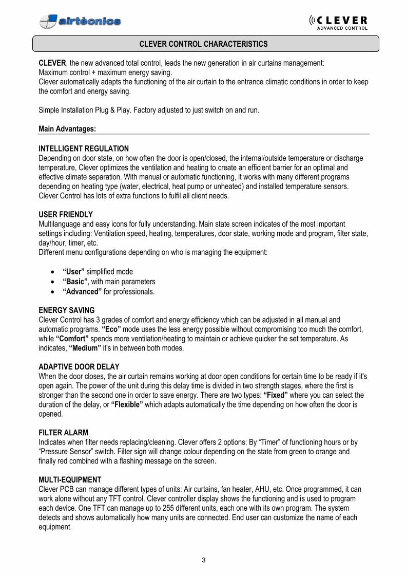
CLEVER CONTROL CHARACTERISTICS
CLEVER, the new advanced total control, leads the new generation in air curtains management: Maximum control + maximum energy saving. Clever automatically adapts the functioning of the air curtain to the entrance climatic conditions in order to keep the comfort and energy saving. Simple Installation Plug & Play. Factory adjusted to just switch on and run. Main Advantages:
INTELLIGENT REGULATION Depending on door state, on how often the door is open/closed, the internal/outside temperature or discharge temperature, Clever optimizes the ventilation and heating to create an efficient barrier for an optimal and effective climate separation. With manual or automatic functioning, it works with many different programs depending on heating type (water, electrical, heat pump or unheated) and installed temperature sensors. Clever Control has lots of extra functions to fulfil all client needs. USER FRIENDLY Multilanguage and easy icons for fully understanding. Main state screen indicates of the most important settings including: Ventilation speed, heating, temperatures, door state, working mode and program, filter state, day/hour, timer, etc. Different menu configurations depending on who is managing the equipment:
• “User” simplified mode
• “Basic”, with main parameters
• “Advanced” for professionals. ENERGY SAVING Clever Control has 3 grades of comfort and energy efficiency which can be adjusted in all manual and automatic programs. “Eco” mode uses the less energy possible without compromising too much the comfort, while “Comfort” spends more ventilation/heating to maintain or achieve quicker the set temperature. As indicates, “Medium” it's in between both modes. ADAPTIVE DOOR DELAY When the door closes, the air curtain remains working at door open conditions for certain time to be ready if it's open again. The power of the unit during this delay time is divided in two strength stages, where the first is stronger than the second one in order to save energy. There are two types: “Fixed” where you can select the duration of the delay, or “Flexible” which adapts automatically the time depending on how often the door is opened. FILTER ALARM Indicates when filter needs replacing/cleaning. Clever offers 2 options: By “Timer” of functioning hours or by “Pressure Sensor” switch. Filter sign will change colour depending on the state from green to orange and finally red combined with a flashing message on the screen. MULTI-EQUIPMENT Clever PCB can manage different types of units: Air curtains, fan heater, AHU, etc. Once programmed, it can work alone without any TFT control. Clever controller display shows the functioning and is used to program each device. One TFT can manage up to 255 different units, each one with its own program. The system detects and shows automatically how many units are connected. End user can customize the name of each equipment.
4
TIMER / CALENDAR Once programmed, the air curtain starts and turns off according to the client needs. Calendar function to turn ON/OFF automatically the unit depending on each different day of the week or predefined groups of days. User can select between Day or Night modes with 2 different Set temperatures in order to save energy. BMS CONNECTION Clever uses Modbus RTU protocol to communicate between the PCB and TFT control and it can be connected directly to a Modbus RTU BMS system. Available in the future Modbus Ethernet with extra module. The Clever PCB has several digital IN/OUT and analogical IN/OUT (0-10V) to control/monitory directly the unit (ON/OFF, fan speed, heating, temperature set, alarms, etc.). PC / ANDROID APP Any Windows PC or Android (IOS in the future) device can manage the air curtain with the same functions as the Clever TFT control. If an IP is assigned, the unit can be externally fully controlled thought internet. Extra Wi-Fi module required for Android. FULLY PROGRAMABLE In Advanced configuration mode, user can set the minimum/maximum of many parameters, like ventilation speed or heating when door is open/closed, set the temperatures for day/night and air outlet, the door delay, etc. Advanced functions:
• Intelligent proactive regulation
• Manual / Automatic Functioning
• Energy saving modes: Eco, Medium and Comfort
• Different programs depending on installed temperature sensors
• Lots of functions to fulfil the client needs
• Fixed / Flexible door delay (progressive / adaptive)
• Calendar (Timer ON day/ON night/OFF)
• Alarms: general, filter, anti-freezing, overheating,
• Fans overheating, airflow, fire, external, heating locked, etc.
• Day / Night Temperatures
• Multi-Equipment management
• Multilanguage
• User / Basic / Advanced configurations
• Control lock option
• 3 Temperature sensors: inside, outside and air jet
• Unheated, electrical or water heated, heat pump (also combined)
• Modulating valve for water heated (includes 24VDC power supply)
• AC and EC fans External communication:
• 2 independent Modbus RTU – BMS
• Configurable IN/OUT Digital/Analogical - BMS
• Modbus TCP Ethernet - BMS (optional, available soon)
• PC program (RS485)
• Wi-Fi (optional). Bluetooth (optional, available soon)
• Android application. IOS application (available soon). Both require Wi-Fi module.
• External monitoring (IP, available soon)

5
CLEVER KIT INCLUDES
Clever Control
RJ11 Cable
• Colour TFT screen 2.8 inch
• 114 (h) x 85 (w) x 14 (d) mm
• Prepared for flush-mount installation
• Easy Plug & Play installation
• RJ11 (4 Pins), 7m length (RJ45 (8 Pins) 7/10 m length cable is included together with the air curtain/fan heater (not in clever kit)
Intelligent PCB Box
Door Contact
• Electronic PCB Regulation
• 218 (h) x 140 (w) x 64 (d) mm
• Varnish Protection
• Monitoring Door Status
• Magnetic contact
PCB Power Supply
Outdoor Temperature Sensor
• Input:100-240Vx1 50/60Hz (AC)
• Output: 24V 2A (DC)
• EU 2 pins / BS 3 pins plugs
• Real-time temperature values
• IP65 Protection
INTELLIGENT PCB
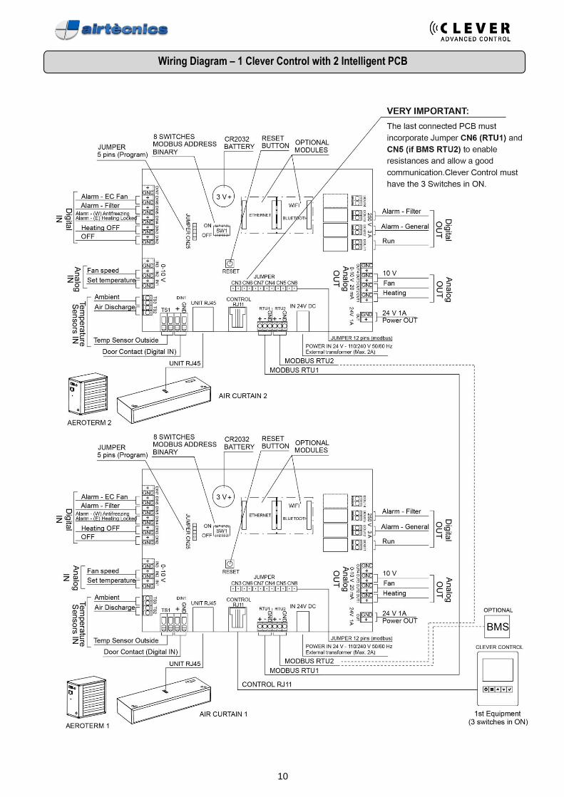
If more than one PCB connected in serial using Modbus protocol, you should turn ON the 3 switches inside the Clever Control and use 3 jumpers at CN3, CN6 and CN7 according to the wiring diagram. All Digital and Analogical IN/OUT are defined by default as indicated in the wiring diagram. Installer can modify and select different functions depending on their needs. The first time you connect the Clever, the equipment will check how many temperature sensors are connected in order to select the program automatically. The Clever Control TFT has an inbuilt temperature sensor used as inside temperature. If you want an external inside temperature sensor (different place than the controller) you should install it at TS3 (once done, TS3 has priority to the Clever Control TFT).

6
Connection Diagram – TEMPERATURE SENSOR SHIELDED CABLE
Connection Diagram – AIR CURTAIN - 1 Clever Control managing 1 unit (1 PCB)
7
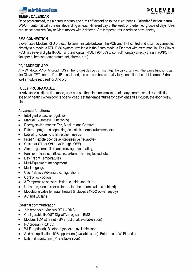
Connection Diagram – AIR CURTAIN - 1 Clever Control managing multiple units (+1 PCB)
Please consult the operating manual of the air curtain for multiple units’ connection.
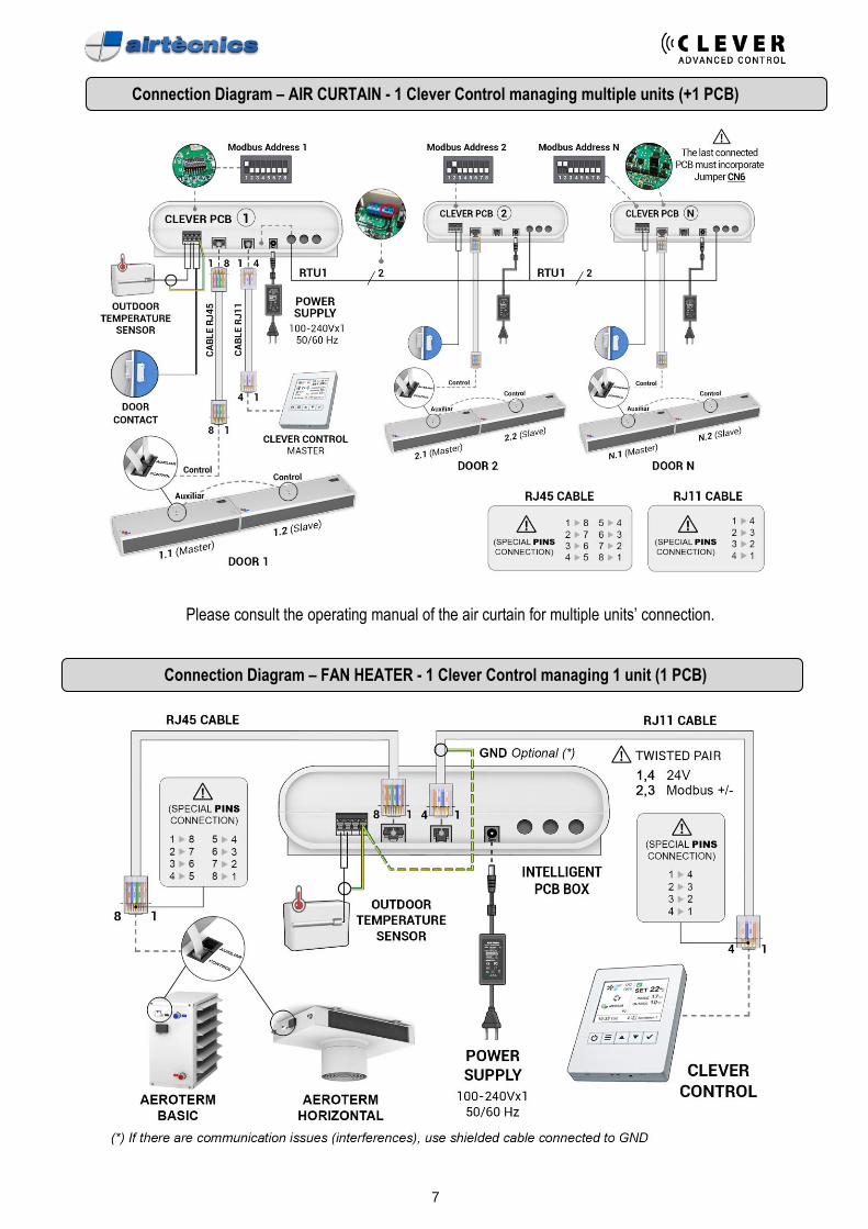
Connection Diagram – FAN HEATER - 1 Clever Control managing 1 unit (1 PCB)
8
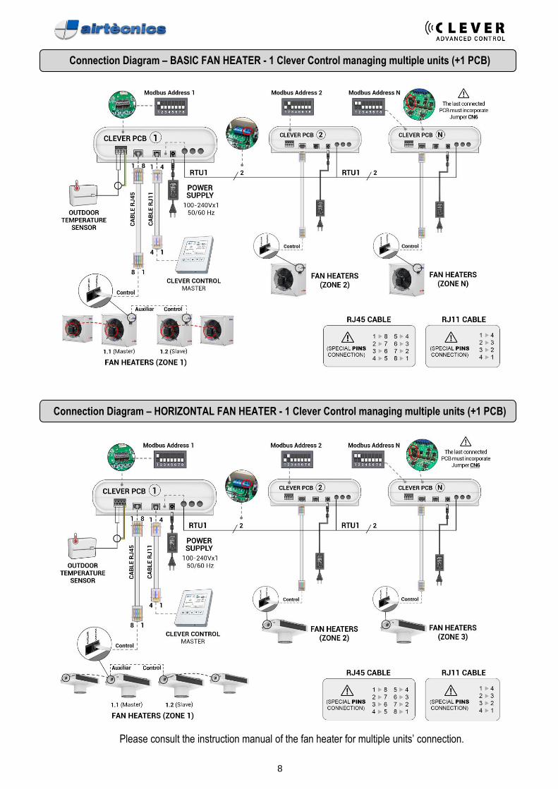
Connection Diagram – BASIC FAN HEATER - 1 Clever Control managing multiple units (+1 PCB)
Connection Diagram – HORIZONTAL FAN HEATER - 1 Clever Control managing multiple units (+1 PCB)
Please consult the instruction manual of the fan heater for multiple units’ connection.
9
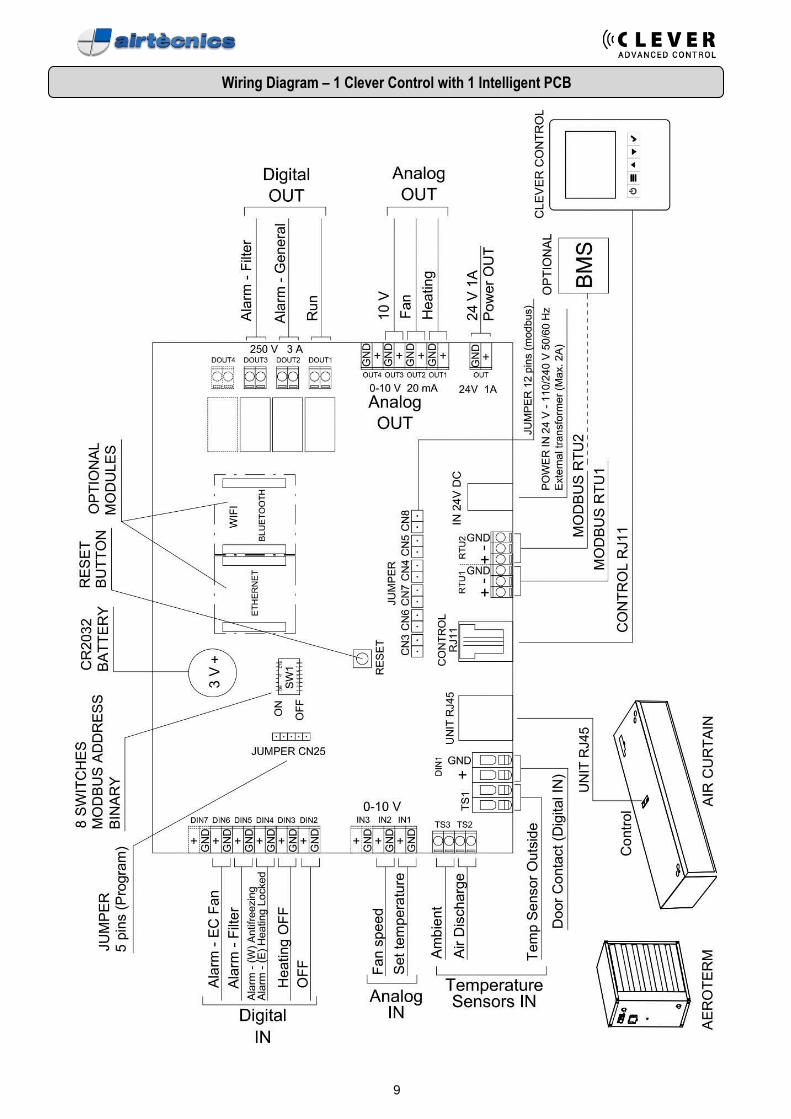
Wiring Diagram – 1 Clever Control with 1 Intelligent PCB
10
Wiring Diagram – 1 Clever Control with 2 Intelligent PCB
11
MODIFY MODBUS ADDRESS
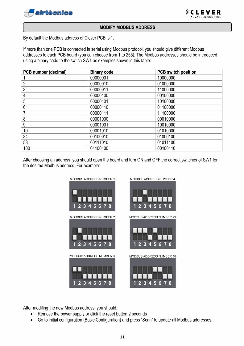
By default the Modbus address of Clever PCB is 1. If more than one PCB is connected in serial using Modbus protocol, you should give different Modbus addresses to each PCB board (you can choose from 1 to 255). The Modbus addresses should be introduced using a binary code to the switch SW1 as examples shown in this table:
PCB number (decimal) Binary code PCB switch position
1 00000001 10000000
2 00000010 01000000
3 00000011 11000000
4 00000100 00100000
5 00000101 10100000
6 00000110 01100000
7 00000111 11100000
8 00001000 00010000
9 00001001 10010000
10 00001010 01010000
34 00100010 01000100
58 00111010 01011100
100 01100100 00100110
After choosing an address, you should open the board and turn ON and OFF the correct switches of SW1 for the desired Modbus address. For example:
After modifing the new Modbus address, you should:
• Remove the power supply or click the reset button 2 seconds
• Go to initial configuration (Basic Configuration) and press “Scan” to update all Modbus addresses.
12
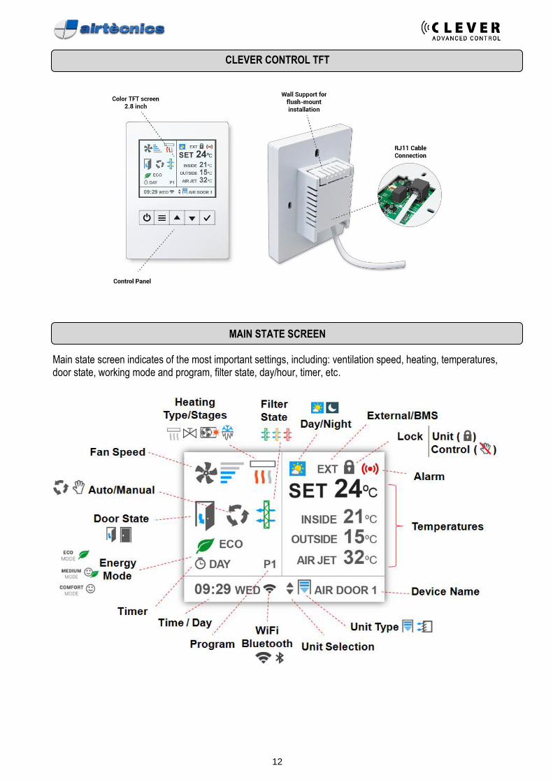
CLEVER CONTROL TFT
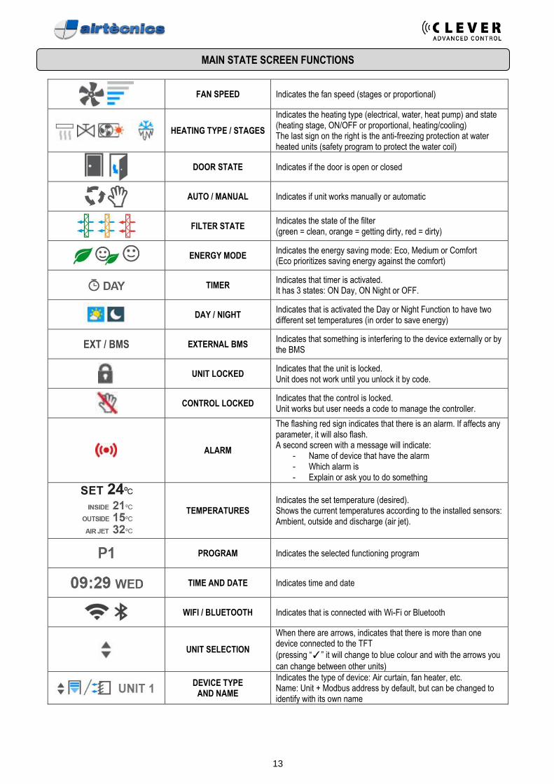
MAIN STATE SCREEN Main state screen indicates of the most important settings, including: ventilation speed, heating, temperatures, door state, working mode and program, filter state, day/hour, timer, etc.
13
MAIN STATE SCREEN FUNCTIONS
FAN SPEED Indicates the fan speed (stages or proportional)
HEATING TYPE / STAGES
Indicates the heating type (electrical, water, heat pump) and state (heating stage, ON/OFF or proportional, heating/cooling) The last sign on the right is the anti-freezing protection at water heated units (safety program to protect the water coil)
DOOR STATE Indicates if the door is open or closed
AUTO / MANUAL Indicates if unit works manually or automatic
FILTER STATE
Indicates the state of the filter (green = clean, orange = getting dirty, red = dirty)
ENERGY MODE
Indicates the energy saving mode: Eco, Medium or Comfort (Eco prioritizes saving energy against the comfort)
TIMER Indicates that timer is activated. It has 3 states: ON Day, ON Night or OFF.
DAY / NIGHT
Indicates that is activated the Day or Night Function to have two different set temperatures (in order to save energy)
EXT / BMS EXTERNAL BMS Indicates that something is interfering to the device externally or by the BMS
UNIT LOCKED
Indicates that the unit is locked. Unit does not work until you unlock it by code.
CONTROL LOCKED
Indicates that the control is locked. Unit works but user needs a code to manage the controller.
ALARM
The flashing red sign indicates that there is an alarm. If affects any parameter, it will also flash. A second screen with a message will indicate:
- Name of device that have the alarm - Which alarm is - Explain or ask you to do something
TEMPERATURES Indicates the set temperature (desired). Shows the current temperatures according to the installed sensors: Ambient, outside and discharge (air jet).
PROGRAM Indicates the selected functioning program
TIME AND DATE Indicates time and date
WIFI / BLUETOOTH Indicates that is connected with Wi-Fi or Bluetooth
UNIT SELECTION
When there are arrows, indicates that there is more than one device connected to the TFT
(pressing “✓” it will change to blue colour and with the arrows you
can change between other units)
DEVICE TYPE
AND NAME
Indicates the type of device: Air curtain, fan heater, etc. Name: Unit + Modbus address by default, but can be changed to identify with its own name
14
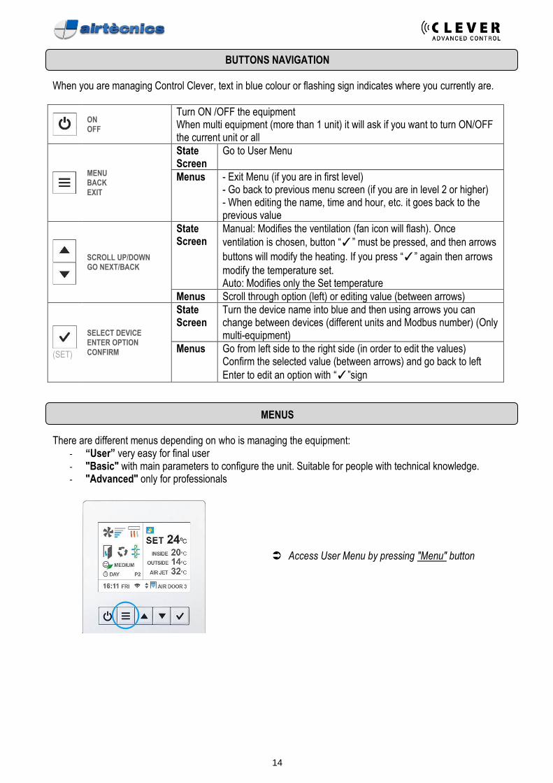
BUTTONS NAVIGATION
When you are managing Control Clever, text in blue colour or flashing sign indicates where you currently are.
ON OFF
Turn ON /OFF the equipment When multi equipment (more than 1 unit) it will ask if you want to turn ON/OFF the current unit or all
MENU BACK EXIT
State Screen
Go to User Menu
Menus - Exit Menu (if you are in first level) - Go back to previous menu screen (if you are in level 2 or higher) - When editing the name, time and hour, etc. it goes back to the previous value
SCROLL UP/DOWN GO NEXT/BACK
State Screen
Manual: Modifies the ventilation (fan icon will flash). Once
ventilation is chosen, button “✓” must be pressed, and then arrows
buttons will modify the heating. If you press “✓” again then arrows
modify the temperature set. Auto: Modifies only the Set temperature
Menus Scroll through option (left) or editing value (between arrows)
(SET)
SELECT DEVICE ENTER OPTION CONFIRM
State Screen
Turn the device name into blue and then using arrows you can change between devices (different units and Modbus number) (Only multi-equipment)
Menus Go from left side to the right side (in order to edit the values) Confirm the selected value (between arrows) and go back to left
Enter to edit an option with “✓”sign
MENUS There are different menus depending on who is managing the equipment:
- “User” very easy for final user - "Basic" with main parameters to configure the unit. Suitable for people with technical knowledge. - "Advanced" only for professionals
Access User Menu by pressing "Menu" button
15
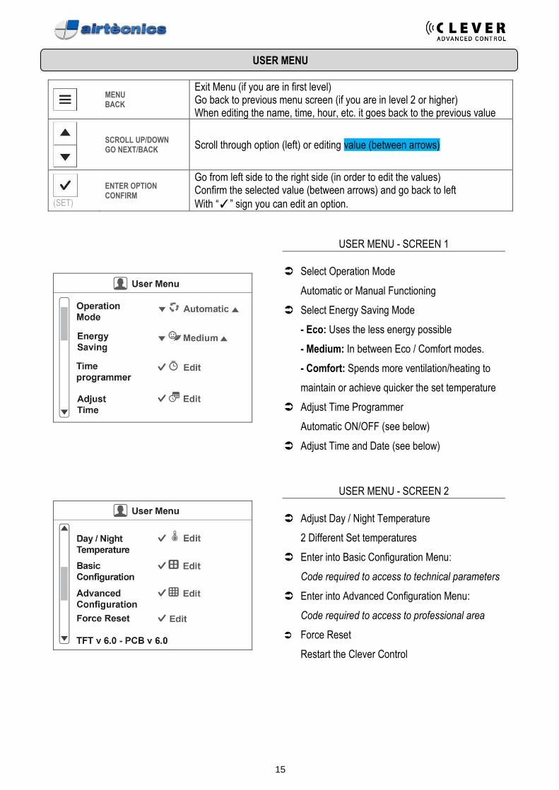
USER MENU
MENU BACK
Exit Menu (if you are in first level) Go back to previous menu screen (if you are in level 2 or higher) When editing the name, time, hour, etc. it goes back to the previous value
SCROLL UP/DOWN GO NEXT/BACK Scroll through option (left) or editing value (between arrows)
(SET)
ENTER OPTION CONFIRM
Go from left side to the right side (in order to edit the values) Confirm the selected value (between arrows) and go back to left
With “✓” sign you can edit an option.
USER MENU - SCREEN 1
Select Operation Mode
Automatic or Manual Functioning
Select Energy Saving Mode
- Eco: Uses the less energy possible
- Medium: In between Eco / Comfort modes.
- Comfort: Spends more ventilation/heating to
maintain or achieve quicker the set temperature
Adjust Time Programmer
Automatic ON/OFF (see below)
Adjust Time and Date (see below)
USER MENU - SCREEN 2
Adjust Day / Night Temperature
2 Different Set temperatures
Enter into Basic Configuration Menu:
Code required to access to technical parameters
Enter into Advanced Configuration Menu:
Code required to access to professional area
Force Reset
Restart the Clever Control
16
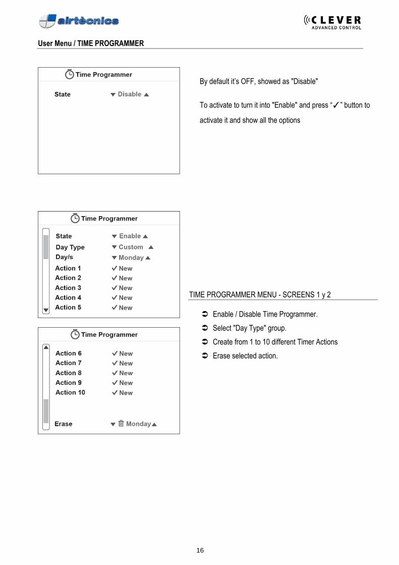
User Menu / TIME PROGRAMMER
By default it’s OFF, showed as "Disable"
To activate to turn it into "Enable" and press “✓” button to
activate it and show all the options
TIME PROGRAMMER MENU - SCREENS 1 y 2
Enable / Disable Time Programmer.
Select "Day Type" group.
Create from 1 to 10 different Timer Actions
Erase selected action.
17
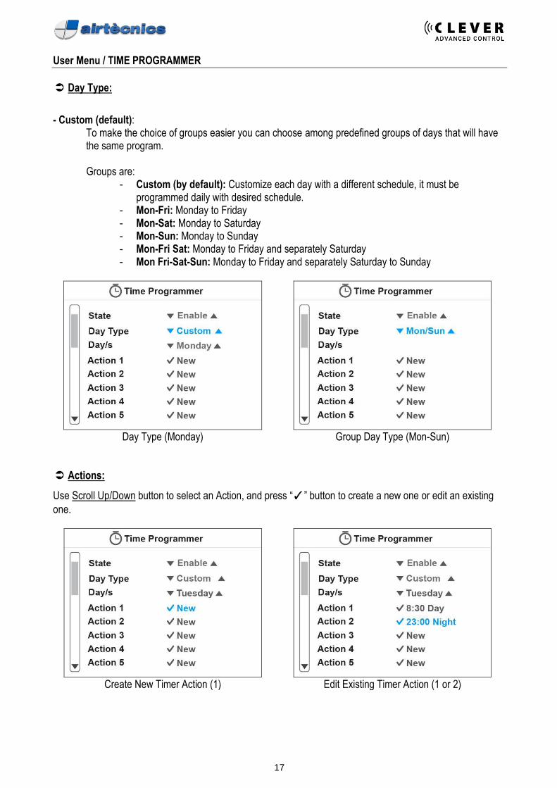
User Menu / TIME PROGRAMMER
Day Type:
- Custom (default):
To make the choice of groups easier you can choose among predefined groups of days that will have the same program.
Groups are:
- Custom (by default): Customize each day with a different schedule, it must be programmed daily with desired schedule.
- Mon-Fri: Monday to Friday - Mon-Sat: Monday to Saturday - Mon-Sun: Monday to Sunday - Mon-Fri Sat: Monday to Friday and separately Saturday - Mon Fri-Sat-Sun: Monday to Friday and separately Saturday to Sunday
Day Type (Monday) Group Day Type (Mon-Sun)
Actions:
Use Scroll Up/Down button to select an Action, and press “✓” button to create a new one or edit an existing
one.
Create New Timer Action (1) Edit Existing Timer Action (1 or 2)
18
User Menu / Time Programmer / ACTIONS
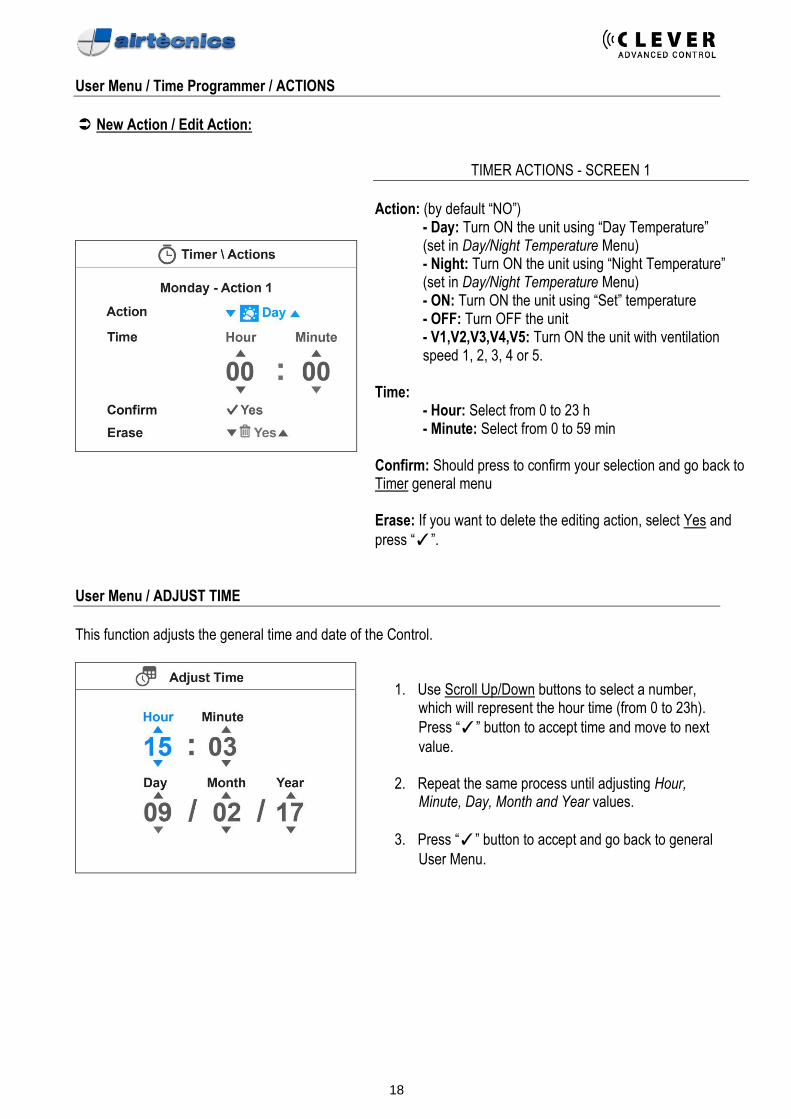
New Action / Edit Action:
TIMER ACTIONS - SCREEN 1
Action: (by default “NO”)
- Day: Turn ON the unit using “Day Temperature” (set in Day/Night Temperature Menu) - Night: Turn ON the unit using “Night Temperature” (set in Day/Night Temperature Menu) - ON: Turn ON the unit using “Set” temperature - OFF: Turn OFF the unit - V1,V2,V3,V4,V5: Turn ON the unit with ventilation speed 1, 2, 3, 4 or 5.
Time:
- Hour: Select from 0 to 23 h - Minute: Select from 0 to 59 min
Confirm: Should press to confirm your selection and go back to Timer general menu Erase: If you want to delete the editing action, select Yes and
press “✓”.
User Menu / ADJUST TIME
This function adjusts the general time and date of the Control.
1. Use Scroll Up/Down buttons to select a number,
which will represent the hour time (from 0 to 23h).
Press “✓” button to accept time and move to next
value.
2. Repeat the same process until adjusting Hour, Minute, Day, Month and Year values.
3. Press “✓” button to accept and go back to general
User Menu.
19
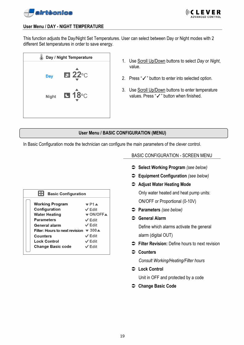
User Menu / DAY - NIGHT TEMPERATURE
This function adjusts the Day/Night Set Temperatures. User can select between Day or Night modes with 2 different Set temperatures in order to save energy.
1. Use Scroll Up/Down buttons to select Day or Night,
value.
2. Press “✓” button to enter into selected option.
3. Use Scroll Up/Down buttons to enter temperature
values. Press “✓” button when finished.
User Menu / BASIC CONFIGURATION (MENU) In Basic Configuration mode the technician can configure the main parameters of the clever control.
BASIC CONFIGURATION - SCREEN MENU
Select Working Program (see below)
Equipment Configuration (see below)
Adjust Water Heating Mode
Only water heated and heat pump units:
ON/OFF or Proportional (0-10V)
Parameters (see below)
General Alarm
Define which alarms activate the general
alarm (digital OUT)
Filter Revision: Define hours to next revision
Counters
Consult Working/Heating/Filter hours
Lock Control
Unit in OFF and protected by a code
Change Basic Code
20
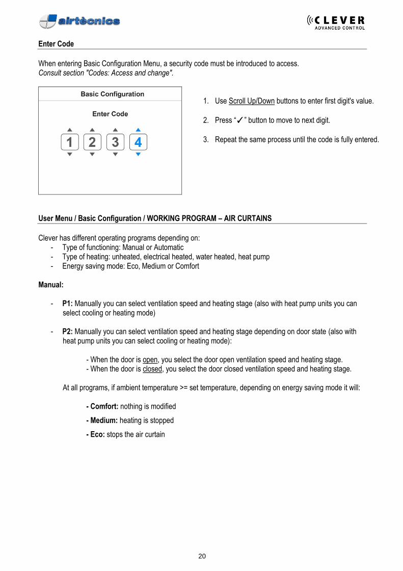
Enter Code
When entering Basic Configuration Menu, a security code must be introduced to access. Consult section "Codes: Access and change".
1. Use Scroll Up/Down buttons to enter first digit's value.
2. Press “✓” button to move to next digit.
3. Repeat the same process until the code is fully entered.
User Menu / Basic Configuration / WORKING PROGRAM – AIR CURTAINS
Clever has different operating programs depending on:
- Type of functioning: Manual or Automatic - Type of heating: unheated, electrical heated, water heated, heat pump - Energy saving mode: Eco, Medium or Comfort
Manual:
- P1: Manually you can select ventilation speed and heating stage (also with heat pump units you can select cooling or heating mode)
- P2: Manually you can select ventilation speed and heating stage depending on door state (also with
heat pump units you can select cooling or heating mode):
- When the door is open, you select the door open ventilation speed and heating stage. - When the door is closed, you select the door closed ventilation speed and heating stage.
At all programs, if ambient temperature >= set temperature, depending on energy saving mode it will:
- Comfort: nothing is modified
- Medium: heating is stopped
- Eco: stops the air curtain
21
User Menu / Basic Configuration / WORKING PROGRAM – AIR CURTAINS
Automatic: Depending on door state, Clever will regulate itself the ventilation and heating thanks to its temperature sensors and energy saving mode, to achieve the maximum efficiency according to selected parameters.
- P1: Functioning according to: o Set and inside temperature o Door state o Energy saving mode
- P2: Functioning according to:
o Set and external temperature o Door state o Energy saving mode
- P3/4: Functioning according to:
o Door opened: Set Temperature and External Temperature o Door closed: Set Temperature and Inside Temperature o P3/4: Energy saving mode (P3 with door opened always in Comfort Mode)
22
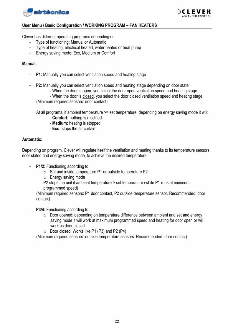
User Menu / Basic Configuration / WORKING PROGRAM – FAN HEATERS
Clever has different operating programs depending on:
- Type of functioning: Manual or Automatic - Type of heating: electrical heated, water heated or heat pump - Energy saving mode: Eco, Medium or Comfort
Manual:
- P1: Manually you can select ventilation speed and heating stage
- P2: Manually you can select ventilation speed and heating stage depending on door state: - When the door is open, you select the door open ventilation speed and heating stage. - When the door is closed, you select the door closed ventilation speed and heating stage.
(Minimum required sensors: door contact)
At all programs, if ambient temperature >= set temperature, depending on energy saving mode it will: - Comfort: nothing is modified - Medium: heating is stopped - Eco: stops the air curtain
Automatic: Depending on program, Clever will regulate itself the ventilation and heating thanks to its temperature sensors, door stated and energy saving mode, to achieve the desired temperature.
- P1/2: Functioning according to: o Set and inside temperature P1 or outside temperature P2 o Energy saving mode P2 stops the unit if ambient temperature > set temperature (while P1 runs at minimum programmed speed)
(Minimum required sensors: P1 door contact, P2 outside temperature sensor. Recommended: door contact)
- P3/4: Functioning according to:
o Door opened: depending on temperature difference between ambient and set and energy saving mode it will work at maximum programmed speed and heating for door open or will work as door closed.
o Door closed: Works like P1 (P3) and P2 (P4) (Minimum required sensors: outside temperature sensors. Recommended: door contact)
23
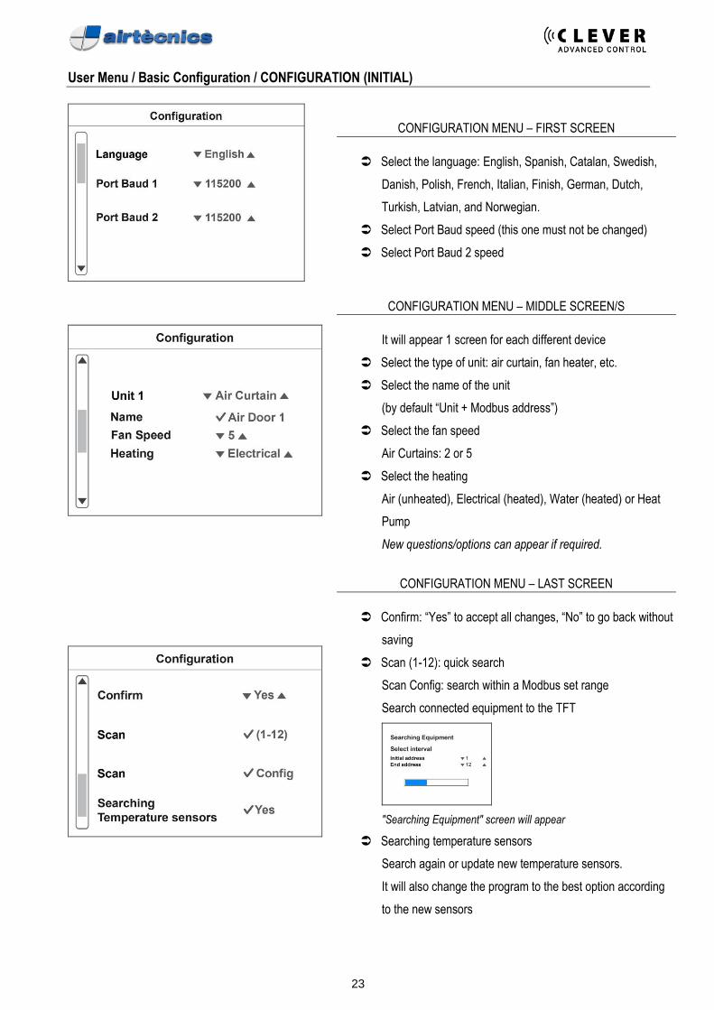
User Menu / Basic Configuration / CONFIGURATION (INITIAL)
CONFIGURATION MENU – FIRST SCREEN
Select the language: English, Spanish, Catalan, Swedish,
Danish, Polish, French, Italian, Finish, German, Dutch,
Turkish, Latvian, and Norwegian.
Select Port Baud speed (this one must not be changed)
Select Port Baud 2 speed
CONFIGURATION MENU – MIDDLE SCREEN/S
It will appear 1 screen for each different device
Select the type of unit: air curtain, fan heater, etc.
Select the name of the unit
(by default “Unit + Modbus address”)
Select the fan speed
Air Curtains: 2 or 5
Select the heating
Air (unheated), Electrical (heated), Water (heated) or Heat
Pump
New questions/options can appear if required.
CONFIGURATION MENU – LAST SCREEN
Confirm: “Yes” to accept all changes, “No” to go back without
saving
Scan (1-12): quick search
Scan Config: search within a Modbus set range
Search connected equipment to the TFT
"Searching Equipment" screen will appear
Searching temperature sensors
Search again or update new temperature sensors.
It will also change the program to the best option according
to the new sensors
24
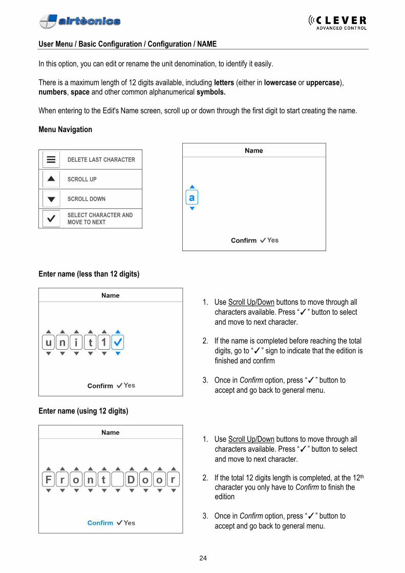
User Menu / Basic Configuration / Configuration / NAME
In this option, you can edit or rename the unit denomination, to identify it easily. There is a maximum length of 12 digits available, including letters (either in lowercase or uppercase), numbers, space and other common alphanumerical symbols. When entering to the Edit's Name screen, scroll up or down through the first digit to start creating the name. Menu Navigation
DELETE LAST CHARACTER
SCROLL UP
SCROLL DOWN
SELECT CHARACTER AND MOVE TO NEXT
Enter name (less than 12 digits)
1. Use Scroll Up/Down buttons to move through all
characters available. Press “✓” button to select
and move to next character.
2. If the name is completed before reaching the total
digits, go to “✓” sign to indicate that the edition is
finished and confirm
3. Once in Confirm option, press “✓” button to
accept and go back to general menu.
Enter name (using 12 digits)
1. Use Scroll Up/Down buttons to move through all
characters available. Press “✓” button to select
and move to next character.
2. If the total 12 digits length is completed, at the 12th character you only have to Confirm to finish the edition
3. Once in Confirm option, press “✓” button to
accept and go back to general menu.
25
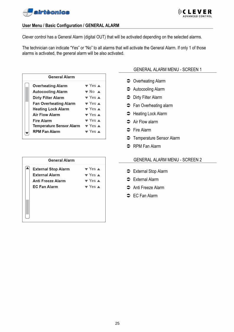
User Menu / Basic Configuration / GENERAL ALARM
Clever control has a General Alarm (digital OUT) that will be activated depending on the selected alarms. The technician can indicate “Yes” or “No” to all alarms that will activate the General Alarm. If only 1 of those alarms is activated, the general alarm will be also activated.
GENERAL ALARM MENU - SCREEN 1
Overheating Alarm
Autocooling Alarm
Dirty Filter Alarm
Fan Overheating alarm
Heating Lock Alarm
Air Flow alarm
Fire Alarm
Temperature Sensor Alarm
RPM Fan Alarm
GENERAL ALARM MENU - SCREEN 2
External Stop Alarm
External Alarm
Anti Freeze Alarm
EC Fan Alarm
26
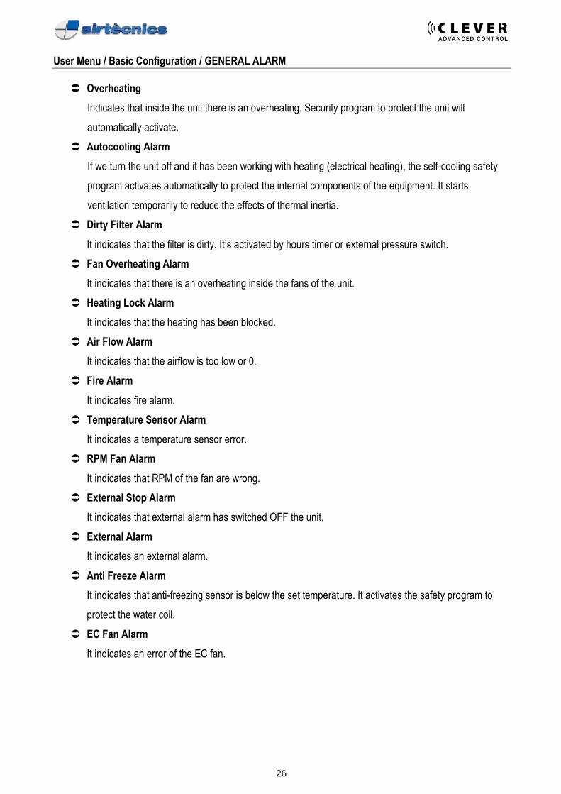
User Menu / Basic Configuration / GENERAL ALARM
Overheating
Indicates that inside the unit there is an overheating. Security program to protect the unit will
automatically activate.
Autocooling Alarm
If we turn the unit off and it has been working with heating (electrical heating), the self-cooling safety
program activates automatically to protect the internal components of the equipment. It starts
ventilation temporarily to reduce the effects of thermal inertia.
Dirty Filter Alarm
It indicates that the filter is dirty. It’s activated by hours timer or external pressure switch.
Fan Overheating Alarm
It indicates that there is an overheating inside the fans of the unit.
Heating Lock Alarm
It indicates that the heating has been blocked.
Air Flow Alarm
It indicates that the airflow is too low or 0.
Fire Alarm
It indicates fire alarm.
Temperature Sensor Alarm
It indicates a temperature sensor error.
RPM Fan Alarm
It indicates that RPM of the fan are wrong.
External Stop Alarm
It indicates that external alarm has switched OFF the unit.
External Alarm
It indicates an external alarm.
Anti Freeze Alarm
It indicates that anti-freezing sensor is below the set temperature. It activates the safety program to
protect the water coil.
EC Fan Alarm
It indicates an error of the EC fan.
27
User Menu / Basic Configuration / PARAMETERS
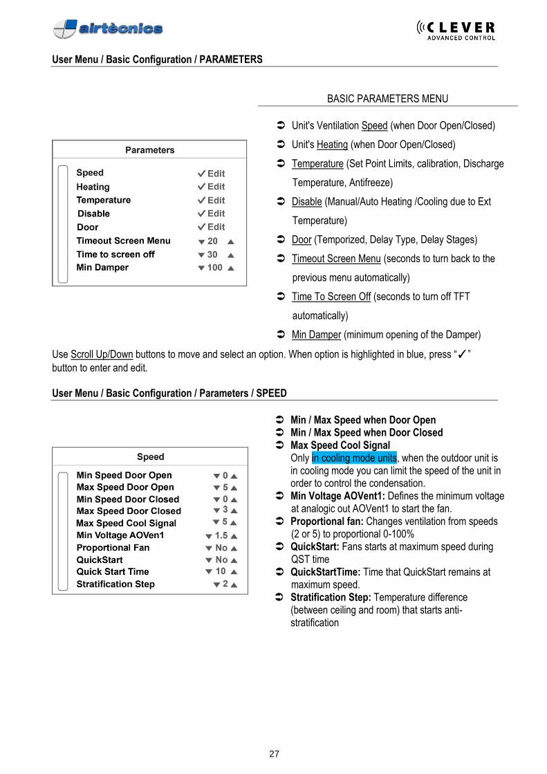
BASIC PARAMETERS MENU
Unit's Ventilation Speed (when Door Open/Closed)
Unit's Heating (when Door Open/Closed)
Temperature (Set Point Limits, calibration, Discharge
Temperature, Antifreeze)
Disable (Manual/Auto Heating /Cooling due to Ext
Temperature)
Door (Temporized, Delay Type, Delay Stages)
Timeout Screen Menu (seconds to turn back to the
previous menu automatically)
Time To Screen Off (seconds to turn off TFT
automatically)
Min Damper (minimum opening of the Damper)
Use Scroll Up/Down buttons to move and select an option. When option is highlighted in blue, press “✓”
button to enter and edit. User Menu / Basic Configuration / Parameters / SPEED
Min / Max Speed when Door Open Min / Max Speed when Door Closed Max Speed Cool Signal
Only in cooling mode units, when the outdoor unit is in cooling mode you can limit the speed of the unit in order to control the condensation.
Min Voltage AOVent1: Defines the minimum voltage at analogic out AOVent1 to start the fan.
Proportional fan: Changes ventilation from speeds (2 or 5) to proportional 0-100%
QuickStart: Fans starts at maximum speed during QST time
QuickStartTime: Time that QuickStart remains at maximum speed.
Stratification Step: Temperature difference (between ceiling and room) that starts anti-stratification

28
User Menu / Basic Configuration / Parameters / HEATING
Min / Max Heating when Door Open Min / Max Heating when Door Closed % Min / Max Heating when Door Open % Min / Max Heating when Door Closed
Stop Heat Pump when Door is Closed
Only for heat pump units, it limits the OFF time of the heat pump when door closes, waiting the selected minutes. If door is opened again before this time elapses, heat pump will not be turned OFF.
Heating Min % Open: defines minimum water flow at any situation to prevent freezing of pipes (Proportional).
User Menu / Basic Configuration / Parameters / TEMPERATURE
Set Point Limits
See below Calibration
See below Discharge Temperature
See below Enable Antifreeze
Uses external temperature sensor as anti-freezing sensor
Temperature Units To choose between ºCelsius or ºFahrenheit.
Cooling ON (by default NO) For water or heat pump coils working in cooling mode.
Set cold pipe Uses cold/heat temperature sensor. If it’s below the set temperature, Clever will start cold mode.
Set heating pipe It is used in two different kind of sensors:
a) Uses cold/heat temperature sensor. If it’s over the set temperature, Clever will start heating mode.
b) Uses return temperature sensor. It does not allow to return the water to more degrees of the set temperature.
29
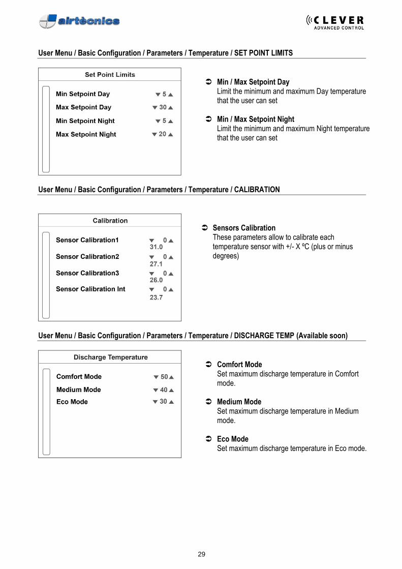
User Menu / Basic Configuration / Parameters / Temperature / SET POINT LIMITS
Min / Max Setpoint Day
Limit the minimum and maximum Day temperature that the user can set
Min / Max Setpoint Night
Limit the minimum and maximum Night temperature that the user can set
User Menu / Basic Configuration / Parameters / Temperature / CALIBRATION
Sensors Calibration
These parameters allow to calibrate each temperature sensor with +/- X ºC (plus or minus degrees)
User Menu / Basic Configuration / Parameters / Temperature / DISCHARGE TEMP (Available soon)
Comfort Mode
Set maximum discharge temperature in Comfort mode.
Medium Mode
Set maximum discharge temperature in Medium mode.
Eco Mode
Set maximum discharge temperature in Eco mode.
30
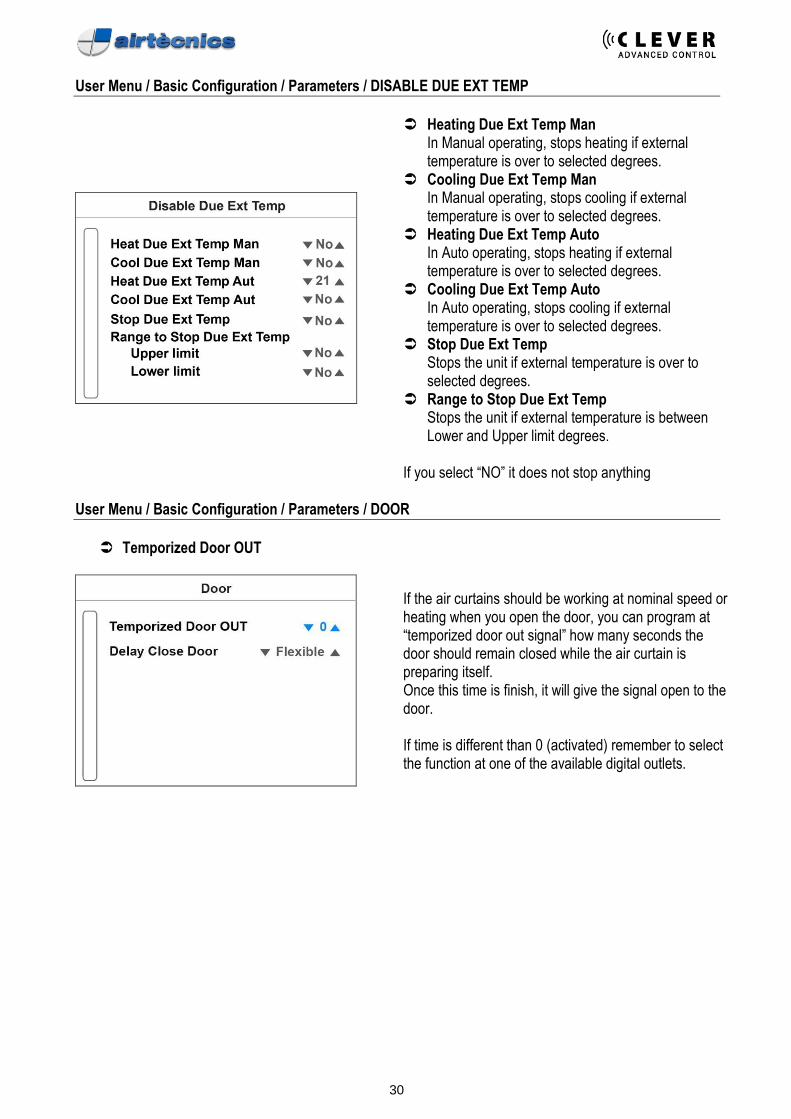
User Menu / Basic Configuration / Parameters / DISABLE DUE EXT TEMP
Heating Due Ext Temp Man In Manual operating, stops heating if external temperature is over to selected degrees.
Cooling Due Ext Temp Man In Manual operating, stops cooling if external temperature is over to selected degrees.
Heating Due Ext Temp Auto In Auto operating, stops heating if external temperature is over to selected degrees.
Cooling Due Ext Temp Auto In Auto operating, stops cooling if external temperature is over to selected degrees.
Stop Due Ext Temp Stops the unit if external temperature is over to selected degrees.
Range to Stop Due Ext Temp Stops the unit if external temperature is between Lower and Upper limit degrees.
If you select “NO” it does not stop anything
User Menu / Basic Configuration / Parameters / DOOR
Temporized Door OUT
If the air curtains should be working at nominal speed or heating when you open the door, you can program at “temporized door out signal” how many seconds the door should remain closed while the air curtain is preparing itself. Once this time is finish, it will give the signal open to the door. If time is different than 0 (activated) remember to select the function at one of the available digital outlets.
31
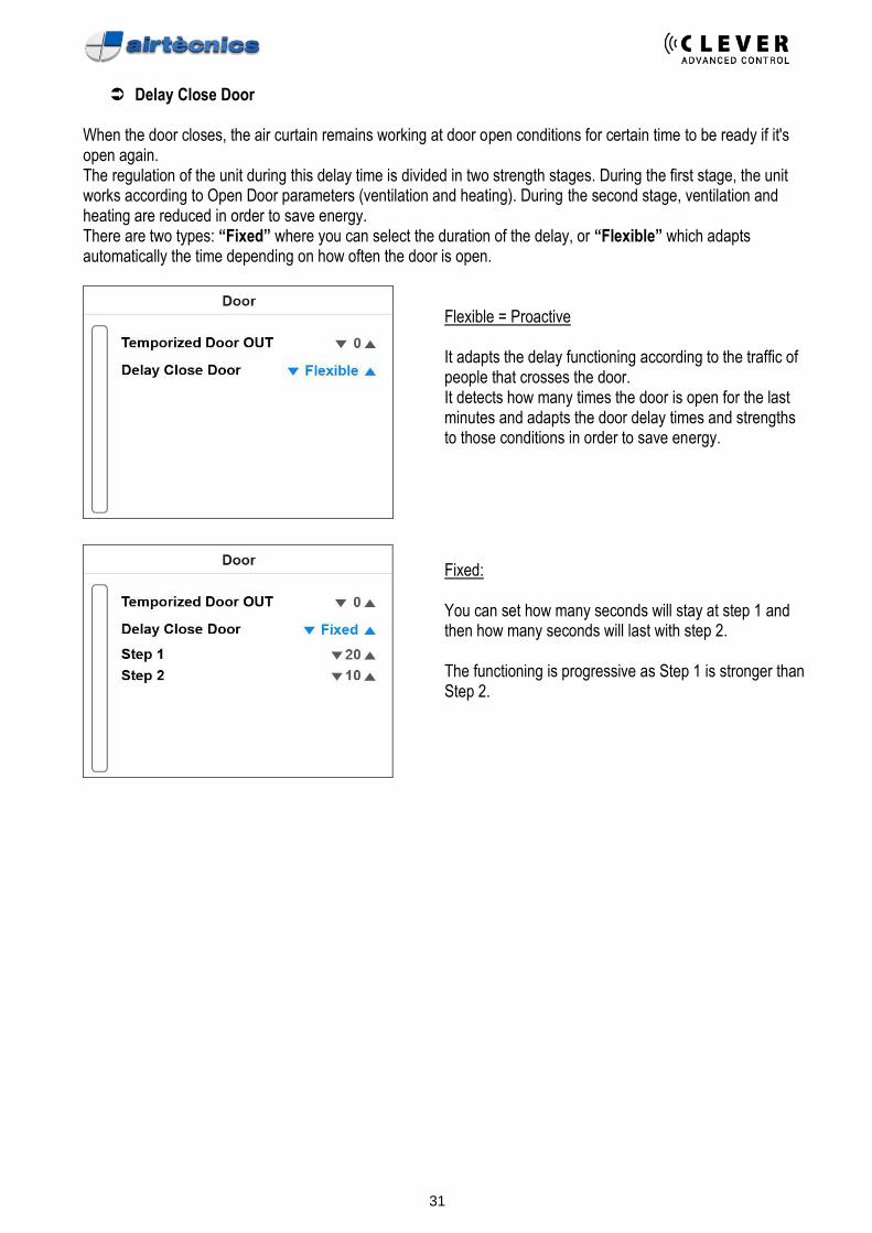
Delay Close Door
When the door closes, the air curtain remains working at door open conditions for certain time to be ready if it's open again. The regulation of the unit during this delay time is divided in two strength stages. During the first stage, the unit works according to Open Door parameters (ventilation and heating). During the second stage, ventilation and heating are reduced in order to save energy. There are two types: “Fixed” where you can select the duration of the delay, or “Flexible” which adapts automatically the time depending on how often the door is open.
Flexible = Proactive It adapts the delay functioning according to the traffic of people that crosses the door. It detects how many times the door is open for the last minutes and adapts the door delay times and strengths to those conditions in order to save energy.
Fixed: You can set how many seconds will stay at step 1 and then how many seconds will last with step 2. The functioning is progressive as Step 1 is stronger than Step 2.
32
User Menu / Basic Configuration / FILTER: HOURS TO NEXT REVISION
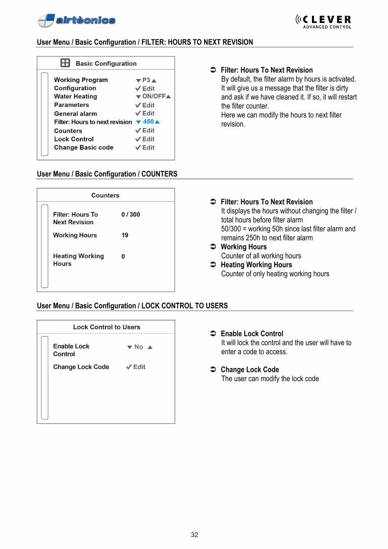
Filter: Hours To Next Revision
By default, the filter alarm by hours is activated. It will give us a message that the filter is dirty and ask if we have cleaned it. If so, it will restart the filter counter. Here we can modify the hours to next filter revision.
User Menu / Basic Configuration / COUNTERS
Filter: Hours To Next Revision
It displays the hours without changing the filter / total hours before filter alarm 50/300 = working 50h since last filter alarm and remains 250h to next filter alarm
Working Hours Counter of all working hours
Heating Working Hours Counter of only heating working hours
User Menu / Basic Configuration / LOCK CONTROL TO USERS
Enable Lock Control
It will lock the control and the user will have to enter a code to access.
Change Lock Code
The user can modify the lock code
33
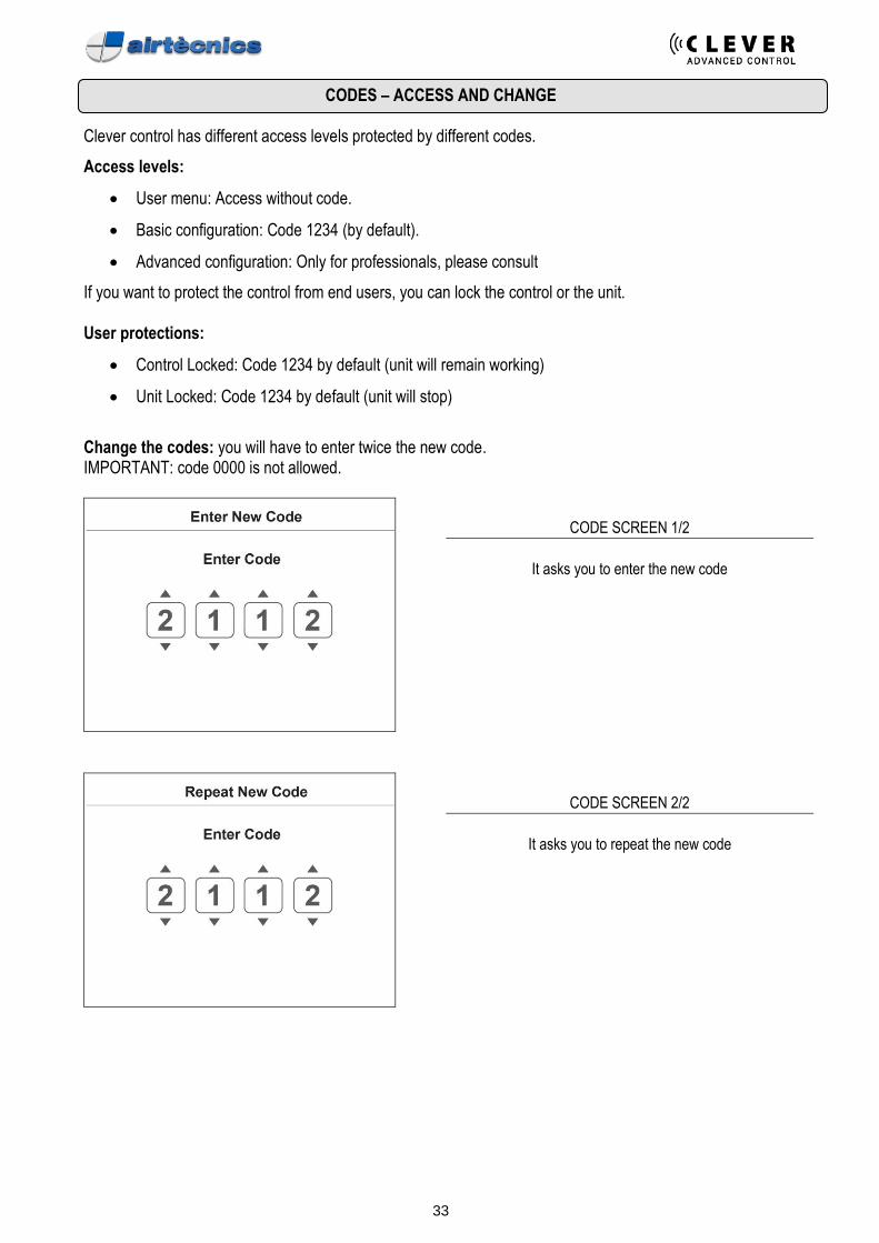
CODES – ACCESS AND CHANGE
Clever control has different access levels protected by different codes.
Access levels:
• User menu: Access without code.
• Basic configuration: Code 1234 (by default).
• Advanced configuration: Only for professionals, please consult
If you want to protect the control from end users, you can lock the control or the unit. User protections:
• Control Locked: Code 1234 by default (unit will remain working)
• Unit Locked: Code 1234 by default (unit will stop)
Change the codes: you will have to enter twice the new code. IMPORTANT: code 0000 is not allowed.
CODE SCREEN 1/2
It asks you to enter the new code
CODE SCREEN 2/2
It asks you to repeat the new code
34
User Menu / ADVANCED CONFIGURATION
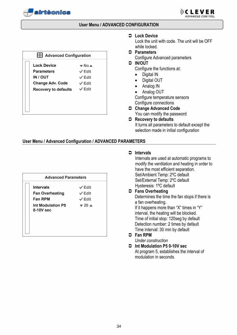
Lock Device Lock the unit with code. The unit will be OFF while locked.
Parameters Configure Advanced parameters
IN/OUT Configure the functions at:
• Digital IN
• Digital OUT
• Analog IN
• Analog OUT Configure temperature sensors Configure connections
Change Advanced Code You can modify the password
Recovery to defaults It turns all parameters to default except the selection made in initial configuration
User Menu / Advanced Configuration / ADVANCED PARAMETERS
Intervals Intervals are used at automatic programs to modify the ventilation and heating in order to have the most efficient separation. Set/Ambient Temp: 2ºC default Set/External Temp: 2ºC default Hysteresis: 1ºC default
Fans Overheating Determines the time the fan stops if there is a fan overheating. If it happens more than “X” times in “Y” interval, the heating will be blocked. Time of initial stop: 120seg by default Detection number: 2 times by default Time interval: 30 min by default
Fan RPM Under construction
Int Modulation P5 0-10V sec At program 5, establishes the interval of modulation in seconds.
35
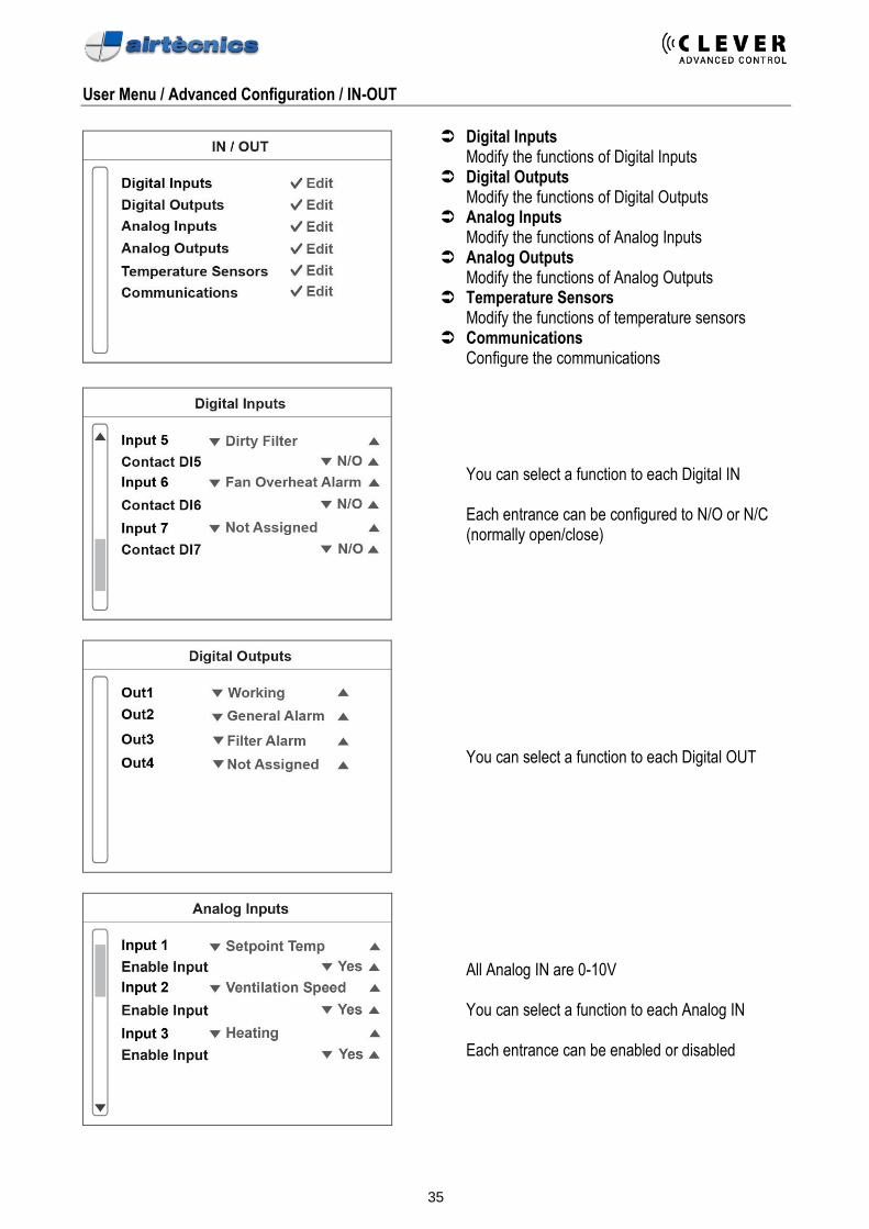
User Menu / Advanced Configuration / IN-OUT
Digital Inputs Modify the functions of Digital Inputs
Digital Outputs Modify the functions of Digital Outputs
Analog Inputs Modify the functions of Analog Inputs
Analog Outputs Modify the functions of Analog Outputs
Temperature Sensors Modify the functions of temperature sensors
Communications Configure the communications
You can select a function to each Digital IN
Each entrance can be configured to N/O or N/C (normally open/close)
You can select a function to each Digital OUT
All Analog IN are 0-10V
You can select a function to each Analog IN
Each entrance can be enabled or disabled
36
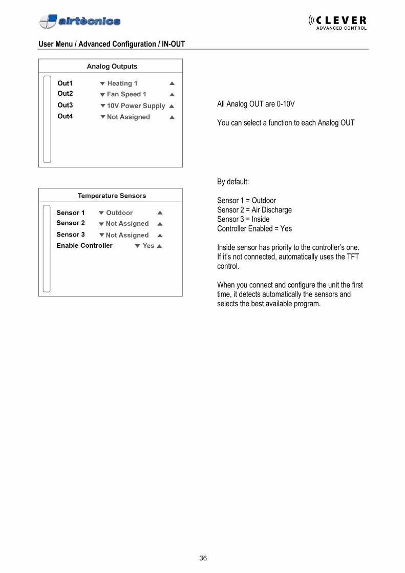
User Menu / Advanced Configuration / IN-OUT
All Analog OUT are 0-10V
You can select a function to each Analog OUT
By default:
Sensor 1 = Outdoor Sensor 2 = Air Discharge Sensor 3 = Inside Controller Enabled = Yes
Inside sensor has priority to the controller’s one. If it’s not connected, automatically uses the TFT control.
When you connect and configure the unit the first time, it detects automatically the sensors and selects the best available program.
37
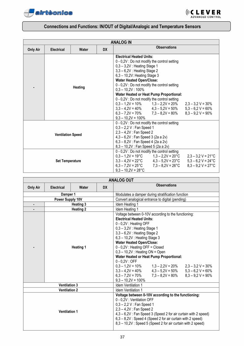
Connections and Functions: IN/OUT of Digital/Analogic and Temperature Sensors
ANALOG IN
Only Air Electrical Water DX Observations
- Heating
Electrical Heated Units: 0 - 0,2V : Do not modify the control setting 0,3 – 3,2V : Heating Stage 1 3,3 – 6,2V : Heating Stage 2 6,3 – 10,2V: Heating Stage 3 Water Heated Open/Close: 0 - 0,2V : Do not modify the control setting 0,3 – 10,2V : 100% Water Heated or Heat Pump Proportional: 0 - 0,2V : Do not modify the control setting 0,3 – 1,2V = 10% 1,3 – 2,2V = 20% 2,3 – 3,2 V = 30% 3,3 – 4,2V = 40% 4,3 – 5,2V = 50% 5,3 – 6,2 V = 60% 6,3 – 7,2V = 70% 7,3 – 8,2V = 80% 8,3 – 9,2 V = 90% 9,3 – 10,2V = 100%
Ventilation Speed
0 - 0,2V : Do not modify the control setting 0,3 – 2,2 V : Fan Speed 1 2,3 – 4,2V : Fan Speed 2 4,3 – 6,2V : Fan Speed 3 (2a a 2v) 6,3 – 8,2V : Fan Speed 4 (2a a 2v) 8,3 – 10,2V : Fan Speed 5 (2a a 2v)
Set Temperature
0 - 0,2V : Do not modify the control setting 0,3 – 1,2V = 19°C 1,3 – 2,2V = 20°C 2,3 – 3,2 V = 21°C 3,3 – 4,2V = 22°C 4,3 – 5,2V = 23°C 5,3 – 6,2 V = 24°C 6,3 – 7,2V = 25°C 7,3 – 8,2V = 26°C 8,3 – 9,2 V = 27°C 9,3 – 10,2V = 28°C
ANALOG OUT
Only Air Electrical Water DX Observations
Damper 1 Modulates a damper during stratification function
Power Supply 10V Convert analogical entrance to digital (pending)
- Heating 3 Idem Heating 1
- Heating 2 Idem Heating 1
- Heating 1
Voltage between 0-10V according to the functioning: Electrical Heated Units: 0 - 0,2V : Heating OFF 0,3 – 3,2V : Heating Stage 1 3,3 – 6,2V : Heating Stage 2 6,3 – 10,2V : Heating Stage 3 Water Heated Open/Close: 0 - 0,2V : Heating OFF = Closed 0,3 – 10,2V : Heating ON = Open Water Heated or Heat Pump Proportional: 0 - 0,2V : OFF 0,3 – 1,2V = 10% 1,3 – 2,2V = 20% 2,3 – 3,2 V = 30% 3,3 – 4,2V = 40% 4,3 – 5,2V = 50% 5,3 – 6,2 V = 60% 6,3 – 7,2V = 70% 7,3 – 8,2V = 80% 8,3 – 9,2 V = 90% 9,3 – 10,2V = 100%
Ventilation 3 Idem Ventilation 1
Ventilation 2 Idem Ventilation 1
Ventilation 1
Voltage between 0-10V according to the functioning: 0 - 0,2V : Ventilation OFF 0,3 – 2,2 V : Fan Speed 1 2,3 – 4,2V : Fan Speed 2 4,3 – 6,2V : Fan Speed 3 (Speed 2 for air curtain with 2 speed) 6,3 – 8,2V : Speed 4 (Speed 2 for air curtain with 2 speed) 8,3 – 10,2V : Speed 5 (Speed 2 for air curtain with 2 speed)
38
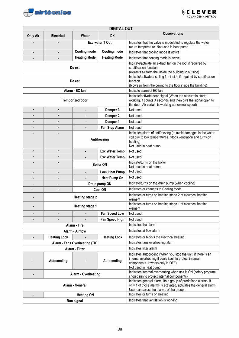
DIGITAL OUT
Only Air Electrical Water DX Observations
- - Exc water T Out Indicates that the valve is modulated to regulate the water return temperature. Not used in heat pump
- - Cooling mode Cooling mode Indicates that cooling mode is active
- - Heating Mode Heating Mode Indicates that heating mode is active
Do ext Indicate/activate an extract fan on the roof if required by stratification function. (extracts air from the inside the building to outside)
Do est Indicate/activate a ceiling fan inside if required by stratification function (blows air from the ceiling to the floor inside the building)
Alarm - EC fan Indicate alarm of EC fan
Temporized door Indicate/activate door signal (When the air curtain starts working, it counts X seconds and then give the signal open to the door. Air curtain is working at nominal speed)
- - - Damper 3 Not used
- - - Damper 2 Not used
- - - Damper 1 Not used
- - - Fan Stop Alarm Not used
- -
Antifreezing
Indicates alarm of antifreezing (to avoid damages in the water coil due to low temperatures. Stops ventilation and turns on heating) Not used in heat pump
- - - Exc Water Temp Not used
- - - Exc Water Temp Not used
- - Boiler ON
Indicate/turns on the boiler Not used in heat pump
- - - Lock Heat Pump Not used
- - - Heat Pump On Not used
- - Drain pump ON Indicate/turns on the drain pump (when cooling)
- - Cool ON Indicates or changes to Cooling mode
- Heating stage 2 Indicates or turns on heating stage 2 of electrical heating element
- Heating stage 1 Indicates or turns on heating stage 1 of electrical heating element
- - - Fan Speed Low Not used
- - - Fan Speed High Not used
Alarm - Fire Indicates fire alarm
Alarm - Airflow Indicates airflow alarm
- Heating Lock - Heating Lock Indicates or blocks the electrical heating
Alarm - Fans Overheating (TK) Indicates fans overheating alarm
Alarm - Filter Indicates filter alarm
- Autocooling - Autocooling
Indicates autocooling (When you stop the unit, if there is an internal overheating it cools itself to protect internal components. It works only in OFF) Not used in heat pump
- Alarm - Overheating Indicates internal overheating when unit is ON (safety program should run to protect internal components)
Alarm - General Indicates general alarm. Its a group of predefined alarms. If only 1 of those alarms is activated, activates the general alarm. User can select the alarms of the group.
- Heating ON Indicates or turns on heating
Run signal Indicates that ventilation is working
39
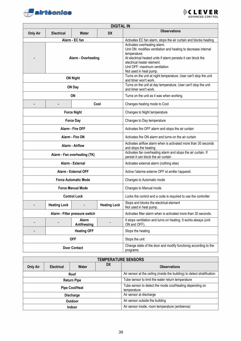
DIGITAL IN
Only Air Electrical Water DX Observations
Alarm - EC fan Activates EC fan alarm, stops the air curtain and blocks heating
- Alarm - Overheating
Activates overheating alarm. Unit ON: modifies ventilation and heating to decrease internal temperature. At electrical heated units if alarm persists it can block the electrical heater element. Unit OFF: maximum ventilation Not used in heat pump.
ON Night Turns on the unit at night temperature. User can't stop the unit and timer won't work.
ON Day Turns on the unit at day temperature. User can't stop the unit and timer won't work.
ON Turns on the unit as it was when working.
- - Cool Changes heating mode to Cool
Force Night Changes to Night temperature
Force Day Changes to Day temperature
Alarm - Fire OFF Activates fire OFF alarm and stops the air curtain
Alarm - Fire ON Activates fire ON alarm and turns on the air curtain
Alarm - Airflow Activates airflow alarm when is activated more than 30 seconds and stops the heating
Alarm - Fan overheating (TK) Activates fan overheating alarm and stops the air curtain. If persist it can block the air curtain
Alarm - External Activates external alarm (nothing else)
Alarm - External OFF Active l’alarme externe OFF et arrête l’appareil.
Force Automatic Mode Changes to Automatic mode
Force Manual Mode Changes to Manual mode
Control Lock Locks the control and a code is required to use the controller
- Heating Lock - Heating Lock Stops and blocks the electrical element Not used in heat pump.
Alarm - Filter pressure switch Activates filter alarm when is activated more than 30 seconds.
- - Alarm
Antifreezing -
It stops ventilation and turns on heating. It works always (unit ON and OFF),
- Heating OFF Stops the heating
OFF Stops the unit
Door Contact Change state of the door and modify functionig according to the programs
TEMPERATURE SENSORS
Only Air Electrical Water DX
Observations
Roof Air sensor at the ceiling (inside the building) to detect stratification
Return Pipe Tube sensor to limit the water return temperature
Pipe Cool/Heat Tube sensor to detect the mode cool/heating depending on temperature
Discharge Air sensor at discharge
Outdoor Air sensor outside the building
Indoor Air sensor inside, room temperature (ambience)
40
PROGRAMS FUNCTIONING
MANUAL FUNCTIONING
When Room Temperature exceeds Set Temperature, concerning Energy Saving mode:
▪ ECO: The air curtain stops itself ▪ MEDIUM: Stops Heating. ▪ COMFORT: Doesn't stop anything.
Program 1 Desired ventilation and heating are manually selected. Program 2 Different ventilation speeds and heating can be manually selected according to the door state (Opened or Closed):
• While door is opened, we select or modify Fan speed or heating of Door Opened
• While door is closed, we select or modify Fan speed or heating of Door Closed
41
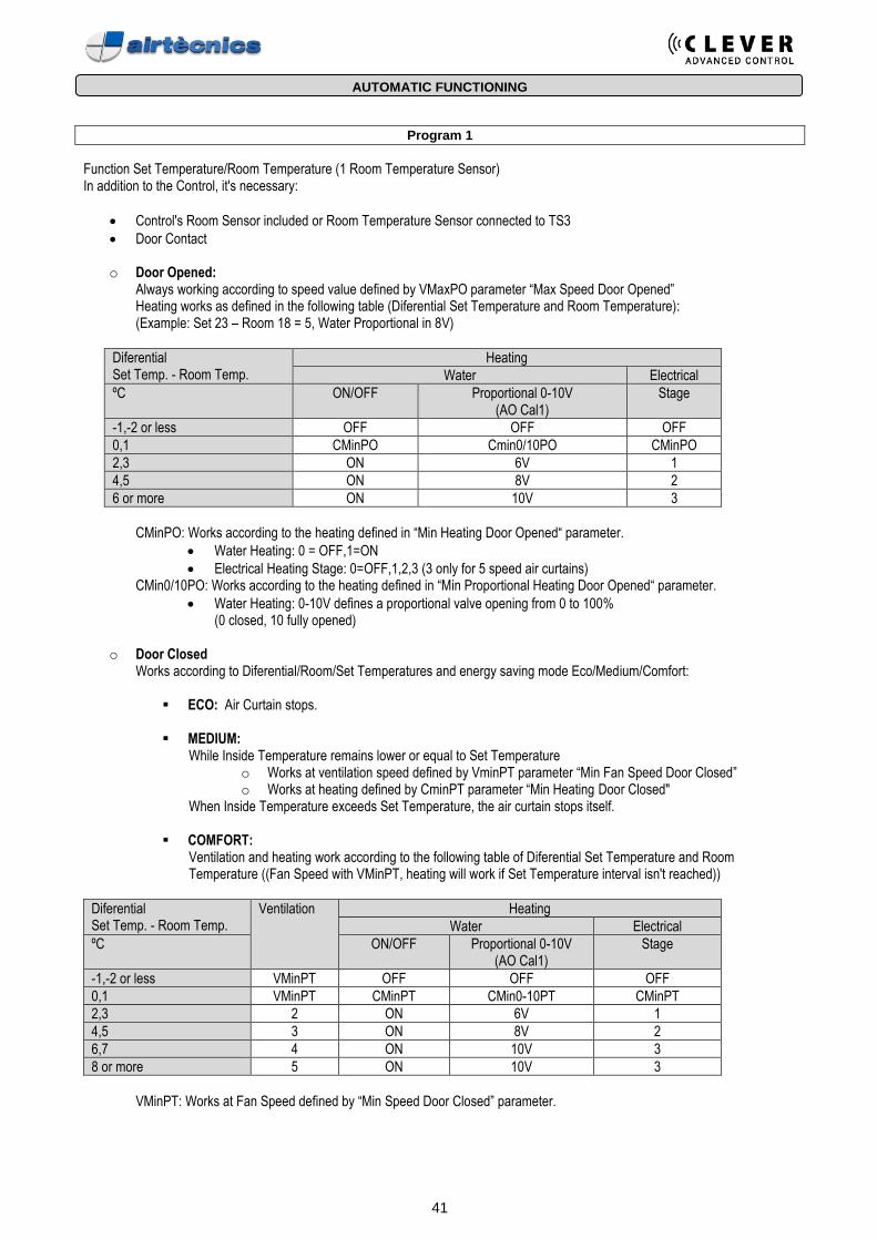
AUTOMATIC FUNCTIONING
Program 1
Function Set Temperature/Room Temperature (1 Room Temperature Sensor) In addition to the Control, it's necessary:
• Control's Room Sensor included or Room Temperature Sensor connected to TS3
• Door Contact
o Door Opened: Always working according to speed value defined by VMaxPO parameter “Max Speed Door Opened” Heating works as defined in the following table (Diferential Set Temperature and Room Temperature): (Example: Set 23 – Room 18 = 5, Water Proportional in 8V)
Diferential Set Temp. - Room Temp.
Heating
Water Electrical
ºC ON/OFF Proportional 0-10V (AO Cal1)
Stage
-1,-2 or less OFF OFF OFF
0,1 CMinPO Cmin0/10PO CMinPO
2,3 ON 6V 1
4,5 ON 8V 2
6 or more ON 10V 3
CMinPO: Works according to the heating defined in “Min Heating Door Opened“ parameter.
• Water Heating: 0 = OFF,1=ON
• Electrical Heating Stage: 0=OFF,1,2,3 (3 only for 5 speed air curtains) CMin0/10PO: Works according to the heating defined in “Min Proportional Heating Door Opened“ parameter.
• Water Heating: 0-10V defines a proportional valve opening from 0 to 100% (0 closed, 10 fully opened)
o Door Closed Works according to Diferential/Room/Set Temperatures and energy saving mode Eco/Medium/Comfort:
▪ ECO: Air Curtain stops.
▪ MEDIUM: While Inside Temperature remains lower or equal to Set Temperature
o Works at ventilation speed defined by VminPT parameter “Min Fan Speed Door Closed” o Works at heating defined by CminPT parameter “Min Heating Door Closed"
When Inside Temperature exceeds Set Temperature, the air curtain stops itself.
▪ COMFORT: Ventilation and heating work according to the following table of Diferential Set Temperature and Room Temperature ((Fan Speed with VMinPT, heating will work if Set Temperature interval isn't reached))
Diferential Set Temp. - Room Temp.
Ventilation Heating
Water Electrical
ºC ON/OFF Proportional 0-10V (AO Cal1)
Stage
-1,-2 or less VMinPT OFF OFF OFF
0,1 VMinPT CMinPT CMin0-10PT CMinPT
2,3 2 ON 6V 1
4,5 3 ON 8V 2
6,7 4 ON 10V 3
8 or more 5 ON 10V 3
VMinPT: Works at Fan Speed defined by “Min Speed Door Closed” parameter.
42
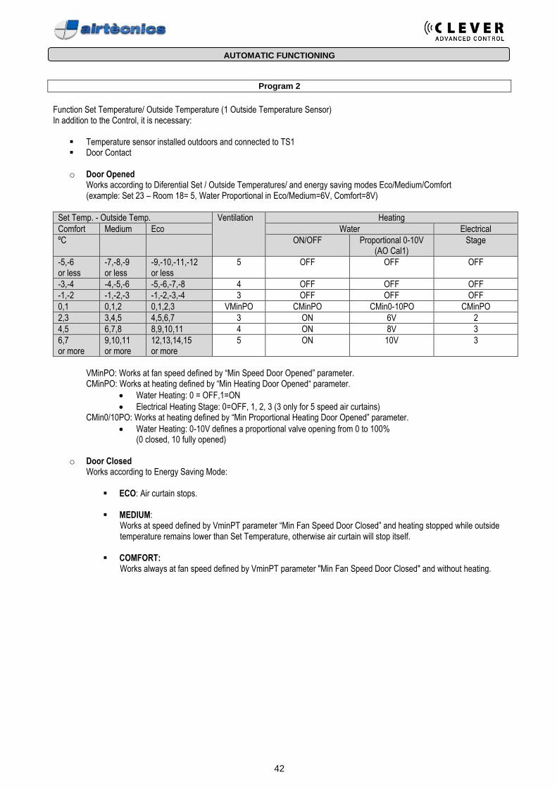
AUTOMATIC FUNCTIONING
Program 2
Function Set Temperature/ Outside Temperature (1 Outside Temperature Sensor) In addition to the Control, it is necessary:
▪ Temperature sensor installed outdoors and connected to TS1 ▪ Door Contact
o Door Opened
Works according to Diferential Set / Outside Temperatures/ and energy saving modes Eco/Medium/Comfort (example: Set 23 – Room 18= 5, Water Proportional in Eco/Medium=6V, Comfort=8V)
Set Temp. - Outside Temp. Ventilation Heating
Comfort Medium Eco Water Electrical
ºC ON/OFF Proportional 0-10V (AO Cal1)
Stage
-5,-6 or less
-7,-8,-9 or less
-9,-10,-11,-12 or less
5 OFF OFF OFF
-3,-4 -4,-5,-6 -5,-6,-7,-8 4 OFF OFF OFF
-1,-2 -1,-2,-3 -1,-2,-3,-4 3 OFF OFF OFF
0,1 0,1,2 0,1,2,3 VMinPO CMinPO CMin0-10PO CMinPO
2,3 3,4,5 4,5,6,7 3 ON 6V 2
4,5 6,7,8 8,9,10,11 4 ON 8V 3
6,7 or more
9,10,11 or more
12,13,14,15 or more
5 ON 10V 3
VMinPO: Works at fan speed defined by “Min Speed Door Opened” parameter. CMinPO: Works at heating defined by “Min Heating Door Opened“ parameter.
• Water Heating: 0 = OFF,1=ON
• Electrical Heating Stage: 0=OFF, 1, 2, 3 (3 only for 5 speed air curtains) CMin0/10PO: Works at heating defined by “Min Proportional Heating Door Opened” parameter.
• Water Heating: 0-10V defines a proportional valve opening from 0 to 100% (0 closed, 10 fully opened)
o Door Closed
Works according to Energy Saving Mode:
▪ ECO: Air curtain stops.
▪ MEDIUM: Works at speed defined by VminPT parameter “Min Fan Speed Door Closed” and heating stopped while outside temperature remains lower than Set Temperature, otherwise air curtain will stop itself.
▪ COMFORT: Works always at fan speed defined by VminPT parameter "Min Fan Speed Door Closed" and without heating.
43
AUTOMATIC FUNCTIONING
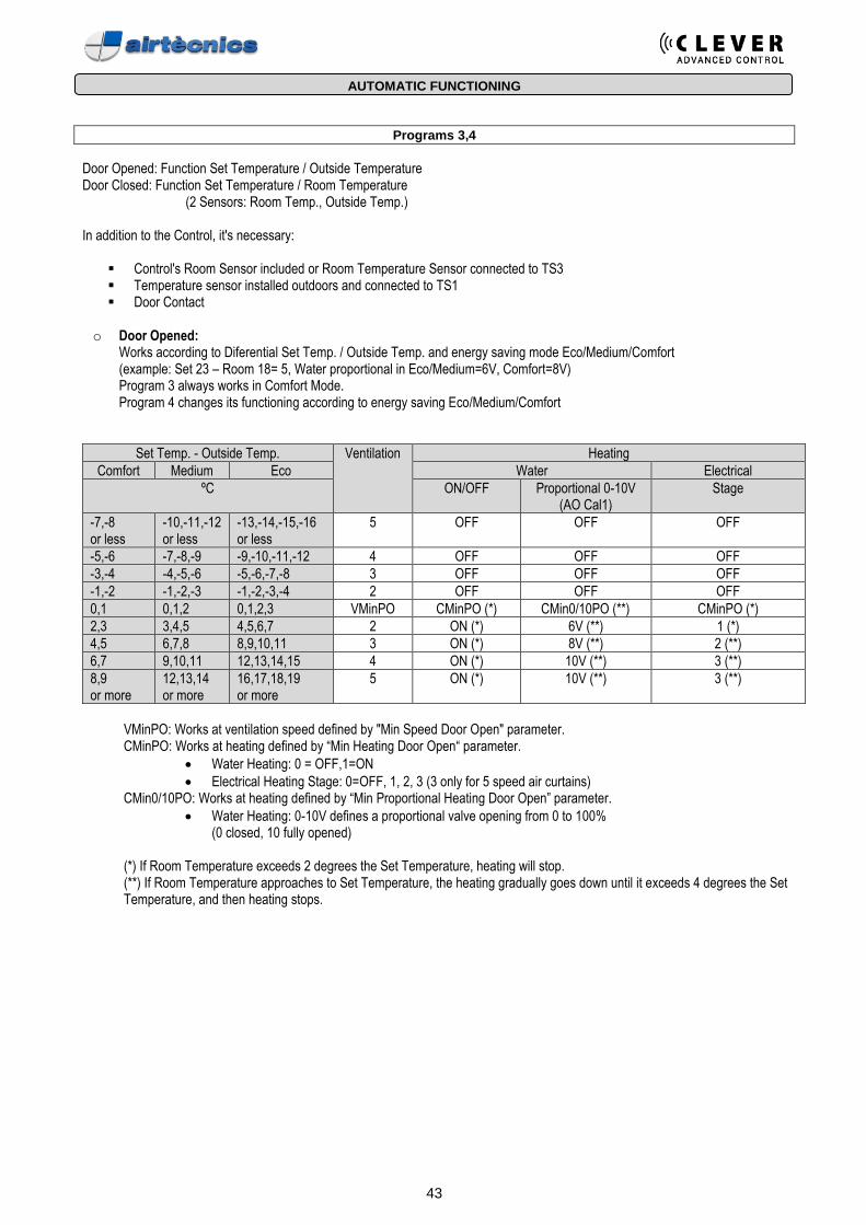
Programs 3,4
Door Opened: Function Set Temperature / Outside Temperature Door Closed: Function Set Temperature / Room Temperature (2 Sensors: Room Temp., Outside Temp.) In addition to the Control, it's necessary:
▪ Control's Room Sensor included or Room Temperature Sensor connected to TS3 ▪ Temperature sensor installed outdoors and connected to TS1 ▪ Door Contact
o Door Opened:
Works according to Diferential Set Temp. / Outside Temp. and energy saving mode Eco/Medium/Comfort (example: Set 23 – Room 18= 5, Water proportional in Eco/Medium=6V, Comfort=8V) Program 3 always works in Comfort Mode. Program 4 changes its functioning according to energy saving Eco/Medium/Comfort
Set Temp. - Outside Temp. Ventilation Heating
Comfort Medium Eco Water Electrical
ºC ON/OFF Proportional 0-10V (AO Cal1)
Stage
-7,-8 or less
-10,-11,-12 or less
-13,-14,-15,-16 or less
5 OFF OFF OFF
-5,-6 -7,-8,-9 -9,-10,-11,-12 4 OFF OFF OFF
-3,-4 -4,-5,-6 -5,-6,-7,-8 3 OFF OFF OFF
-1,-2 -1,-2,-3 -1,-2,-3,-4 2 OFF OFF OFF
0,1 0,1,2 0,1,2,3 VMinPO CMinPO (*) CMin0/10PO (**) CMinPO (*)
2,3 3,4,5 4,5,6,7 2 ON (*) 6V (**) 1 (*)
4,5 6,7,8 8,9,10,11 3 ON (*) 8V (**) 2 (**)
6,7 9,10,11 12,13,14,15 4 ON (*) 10V (**) 3 (**)
8,9 or more
12,13,14 or more
16,17,18,19 or more
5 ON (*) 10V (**) 3 (**)
VMinPO: Works at ventilation speed defined by "Min Speed Door Open" parameter. CMinPO: Works at heating defined by “Min Heating Door Open“ parameter.
• Water Heating: 0 = OFF,1=ON
• Electrical Heating Stage: 0=OFF, 1, 2, 3 (3 only for 5 speed air curtains) CMin0/10PO: Works at heating defined by “Min Proportional Heating Door Open” parameter.
• Water Heating: 0-10V defines a proportional valve opening from 0 to 100% (0 closed, 10 fully opened)
(*) If Room Temperature exceeds 2 degrees the Set Temperature, heating will stop. (**) If Room Temperature approaches to Set Temperature, the heating gradually goes down until it exceeds 4 degrees the Set Temperature, and then heating stops.
44
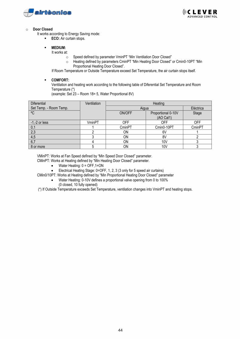
o Door Closed
It works according to Energy Saving mode: ▪ ECO: Air curtain stops.
▪ MEDIUM:
It works at: o Speed defined by parameter VminPT “Min Ventilation Door Closed” o Heating defined by parameters CminPT “Min Heating Door Closed” or Cmin0-10PT “Min
Proportional Heating Door Closed”. If Room Temperature or Outside Temperature exceed Set Temperature, the air curtain stops itself.
▪ COMFORT: Ventilation and heating work according to the following table of Diferential Set Temperature and Room
Temperature (*) (example: Set 23 – Room 18= 5, Water Proportional 8V)
Diferential Set Temp. - Room Temp.
Ventilation Heating
Aigua Elèctrica
ºC ON/OFF Proportional 0-10V (AO Cal1)
Stage
-1,-2 or less VminPT OFF OFF OFF
0,1 1 CminPT Cmin0-10PT CminPT
2,3 2 ON 6V 1
4,5 3 ON 8V 2
6,7 4 ON 10V 3
8 or more 5 ON 10V 3
VMinPT: Works at Fan Speed defined by “Min Speed Door Closed” parameter. CMinPT: Works at Heating defined by “Min Heating Door Closed” parameter.
• Water Heating: 0 = OFF,1=ON
• Electrical Heating Stage: 0=OFF, 1, 2, 3 (3 only for 5 speed air curtains) CMin0/10PT: Works at Heating defined by “Min Proportional Heating Door Closed” parameter
• Water Heating: 0-10V defines a proportional valve opening from 0 to 100% (0 closed, 10 fully opened)
(*) If Outside Temperature exceeds Set Temperature, ventilation changes into VminPT and heating stops.
45
BMS CONTROL
Clever can be managed externally using:
• Digital/Analogic entrances
• Or by via Modbus RTU Although you send wrong orders to the equipment, the unit will not allow combinations that can damage the internal components. The internal PCB has instructions to run the unit safety. For example, if you order to electrical heated air curtain go to 3rd heating stage and 1st ventilation speed, it will allow go to air speed 1 but heating will work at 1st stage only (maximum allowed heating stage for first ventilation). If you stop the ventilation, the heating will also stop except:
• Anti-freezing sensor signal
• Minimum voltage for 0-10V proportional valves (avoid freezing) The minimum and maximum parameters (door open and door close) will be also respected. For instance, you define that maximum speed when the door is closed should be the 2nd. Then if you order the 3rd ventilation speed and door closes, it will change from 3rd to 2nd. If you open again the door it will go to the 3rd.
Digital/Analogic entrances: Clever has several digital IN and analogic IN to modify the functioning of the unit. At the wiring diagrams (beginning of this manual) you can see the default functions of each entrance. There are more functions than entrances, so you can select the most appropriate to cover your needs (advanced menu). All digital IN are NO (Normally Open), but you can change to NC (Normally Closed) at advanced menu. For example, here some default functions for air curtains:
• OFF Unit: Digital IN - DIN2 (free voltage, dry contact)
• OFF Heating: Digital IN - DIN3 (free voltage, dry contact)
• Temperature SET: Analog IN 0-10V (IN1) 0V 0-0,2V Do not modify the control setting 1V 0,3-1,2V = 19ºC 2V 1,3-2,2V = 20ºC 3V 2,3-3,2V = 21ºC 4V 3,3-4,2V = 22ºC 5V 4,3-5,2V = 23ºC 6V 5,3-6,2V = 24ºC 7V 6,3-7,2V = 25ºC 8V 7,3-8,2V = 26ºC 9V 8,3-9,2V = 27ºC 10V 9,3-10,2V = 28ºC
• Ventilation Speed: Analog IN 0-10V (IN2) If 5 speed air curtain, then: 0V 0-0,2V Do not modifies the control setting 2V 0,3-2,2V = Fan Speed 1 4V 2,3-4,2V = Fan Speed 2 6V 4,3-6,2V = Fan Speed 3 8V 6,3-8,2V = Fan Speed 4 10V 8,3-10,2V = Fan Speed 5
• Heating Stage: Analog IN 0-10V - By default there is no entrance, but you can assign an entrance at advanced menu.
All those orders given by digital/analogic inputs have priority to the programs functioning. For instance, if the program is running at maximum speed but you send 6V to (IN2), the unit will change to fan speed 3. It doesn’t matter if the program conditions would change. At this solution there is only 1 manager because all orders from BMS goes to the TFT and then to the Clever PCB.
46
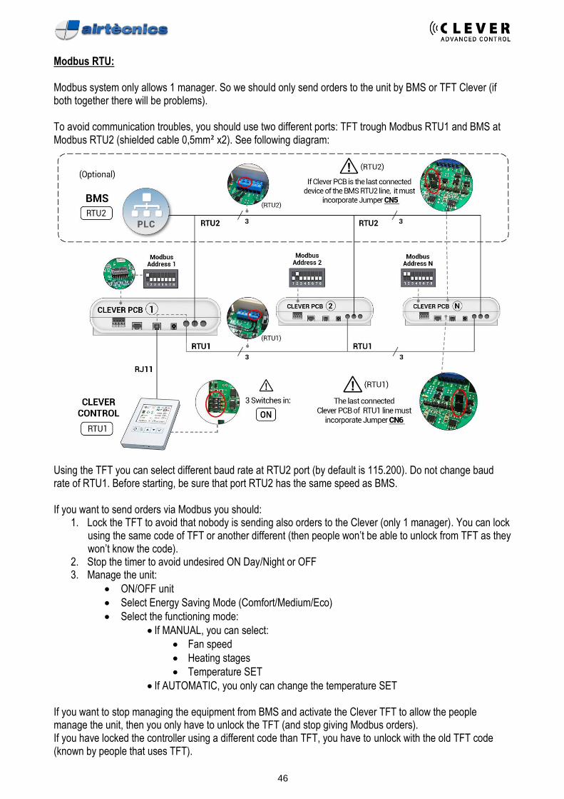
Modbus RTU: Modbus system only allows 1 manager. So we should only send orders to the unit by BMS or TFT Clever (if both together there will be problems). To avoid communication troubles, you should use two different ports: TFT trough Modbus RTU1 and BMS at Modbus RTU2 (shielded cable 0,5mm² x2). See following diagram:
Using the TFT you can select different baud rate at RTU2 port (by default is 115.200). Do not change baud rate of RTU1. Before starting, be sure that port RTU2 has the same speed as BMS. If you want to send orders via Modbus you should:
1. Lock the TFT to avoid that nobody is sending also orders to the Clever (only 1 manager). You can lock using the same code of TFT or another different (then people won’t be able to unlock from TFT as they won’t know the code).
2. Stop the timer to avoid undesired ON Day/Night or OFF 3. Manage the unit:
• ON/OFF unit
• Select Energy Saving Mode (Comfort/Medium/Eco)
• Select the functioning mode:
• If MANUAL, you can select:
• Fan speed
• Heating stages
• Temperature SET
• If AUTOMATIC, you only can change the temperature SET If you want to stop managing the equipment from BMS and activate the Clever TFT to allow the people manage the unit, then you only have to unlock the TFT (and stop giving Modbus orders). If you have locked the controller using a different code than TFT, you have to unlock with the old TFT code (known by people that uses TFT).
47
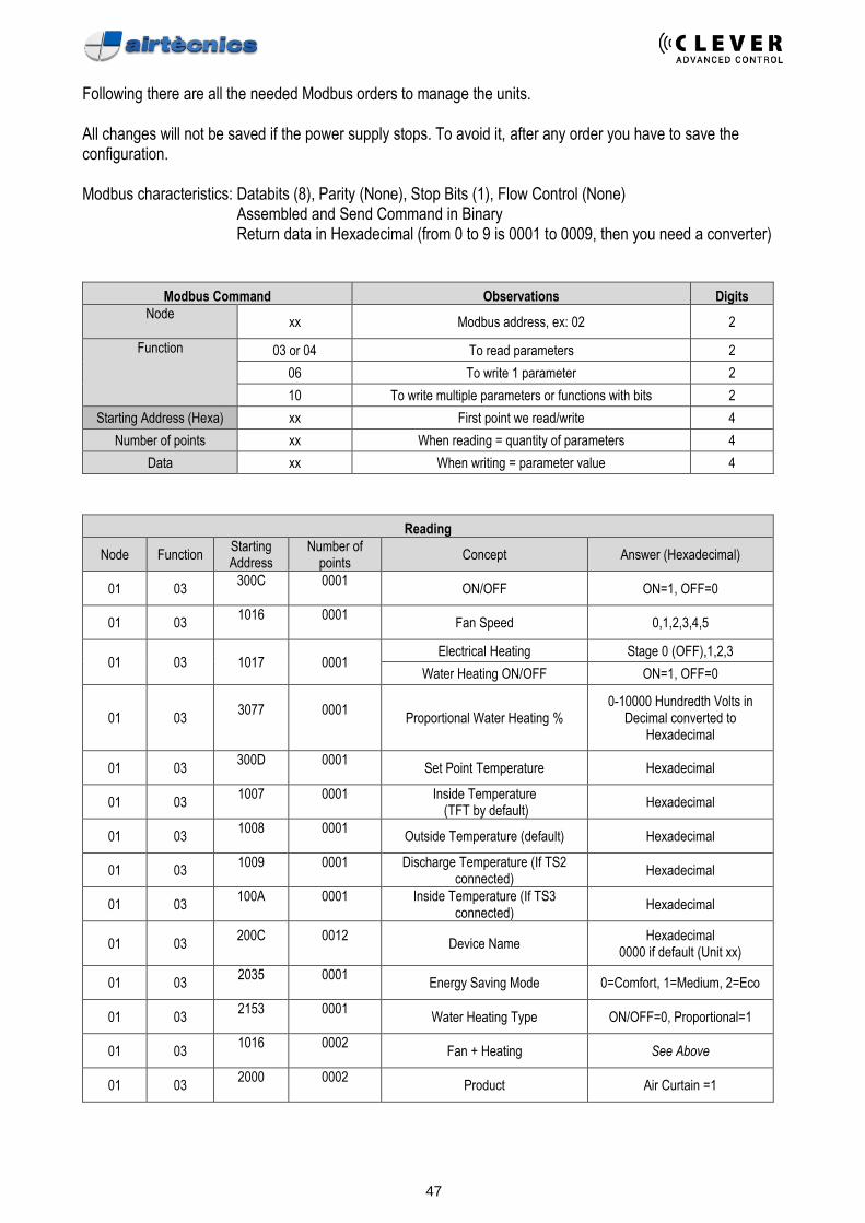
Following there are all the needed Modbus orders to manage the units. All changes will not be saved if the power supply stops. To avoid it, after any order you have to save the configuration. Modbus characteristics: Databits (8), Parity (None), Stop Bits (1), Flow Control (None)
Assembled and Send Command in Binary Return data in Hexadecimal (from 0 to 9 is 0001 to 0009, then you need a converter)
Modbus Command Observations Digits
Node
xx Modbus address, ex: 02 2
Function
03 or 04 To read parameters 2
06 To write 1 parameter 2
10 To write multiple parameters or functions with bits 2
Starting Address (Hexa) xx First point we read/write 4
Number of points xx When reading = quantity of parameters 4
Data xx When writing = parameter value 4
Reading
Node Function Starting Address
Number of points
Concept Answer (Hexadecimal)
01 03 300C
0001
ON/OFF ON=1, OFF=0
01 03 1016
0001
Fan Speed 0,1,2,3,4,5
01 03 1017 0001 Electrical Heating Stage 0 (OFF),1,2,3
Water Heating ON/OFF ON=1, OFF=0
01 03 3077
0001
Proportional Water Heating %
0-10000 Hundredth Volts in Decimal converted to
Hexadecimal
01 03 300D
0001
Set Point Temperature Hexadecimal
01 03 1007
0001
Inside Temperature
(TFT by default) Hexadecimal
01 03 1008
0001
Outside Temperature (default) Hexadecimal
01 03 1009
0001
Discharge Temperature (If TS2
connected) Hexadecimal
01 03 100A
0001
Inside Temperature (If TS3
connected) Hexadecimal
01 03 200C
0012
Device Name
Hexadecimal 0000 if default (Unit xx)
01 03 2035
0001
Energy Saving Mode 0=Comfort, 1=Medium, 2=Eco
01 03 2153
0001
Water Heating Type ON/OFF=0, Proportional=1
01 03 1016
0002
Fan + Heating See Above
01 03 2000
0002
Product Air Curtain =1
48
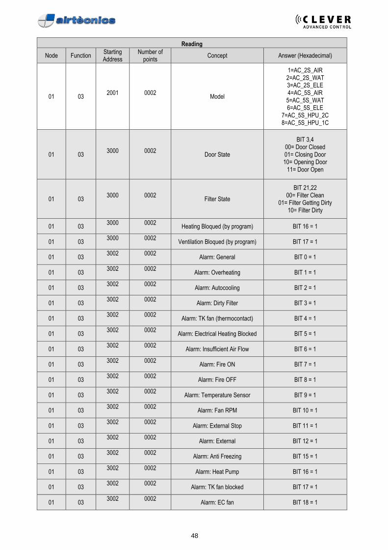
Reading
Node Function Starting Address
Number of points
Concept Answer (Hexadecimal)
01 03 2001
0002
Model
1=AC_2S_AIR 2=AC_2S_WAT 3=AC_2S_ELE 4=AC_5S_AIR
5=AC_5S_WAT 6=AC_5S_ELE
7=AC_5S_HPU_2C 8=AC_5S_HPU_1C
01 03 3000
0002
Door State
BIT 3,4 00= Door Closed 01= Closing Door 10= Opening Door
11= Door Open
01 03 3000
0002
Filter State
BIT 21,22 00= Filter Clean
01= Filter Getting Dirty 10= Filter Dirty
01 03 3000
0002
Heating Bloqued (by program) BIT 16 = 1
01 03 3000
0002
Ventilation Bloqued (by program) BIT 17 = 1
01 03 3002
0002
Alarm: General BIT 0 = 1
01 03 3002
0002
Alarm: Overheating BIT 1 = 1
01 03 3002
0002
Alarm: Autocooling BIT 2 = 1
01 03 3002
0002
Alarm: Dirty Filter BIT 3 = 1
01 03 3002
0002
Alarm: TK fan (thermocontact) BIT 4 = 1
01 03 3002
0002
Alarm: Electrical Heating Blocked BIT 5 = 1
01 03 3002
0002
Alarm: Insufficient Air Flow BIT 6 = 1
01 03 3002
0002
Alarm: Fire ON BIT 7 = 1
01 03 3002
0002
Alarm: Fire OFF BIT 8 = 1
01 03 3002
0002
Alarm: Temperature Sensor BIT 9 = 1
01 03 3002
0002
Alarm: Fan RPM BIT 10 = 1
01 03 3002
0002
Alarm: External Stop BIT 11 = 1
01 03 3002
0002
Alarm: External BIT 12 = 1
01 03 3002
0002
Alarm: Anti Freezing BIT 15 = 1
01 03 3002
0002
Alarm: Heat Pump BIT 16 = 1
01 03 3002
0002
Alarm: TK fan blocked BIT 17 = 1
01 03 3002
0002
Alarm: EC fan BIT 18 = 1
49
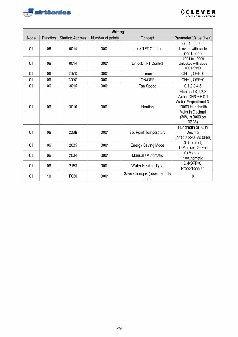
Writing
Node Function Starting Address Number of points Concept Parameter Value (Hex)
01 06 0014 0001 Lock TFT Control 0001 to 9999
Locked with code 0001-9999
01 06 0014 0001 Unlock TFT Control -0001 to - 9999
Unlocked with code 0001-9999
01 06 207D 0001 Timer ON=1, OFF=0
01 06 300C 0001 ON/OFF ON=1, OFF=0
01 06 3015 0001 Fan Speed 0,1,2,3,4,5
01 06 3016 0001 Heating
Electrical 0,1,2,3 Water ON/OFF 0,1
Water Proportional 0-10000 Hundredth Volts in Decimal (30% is 3000 so
0BB8)
01 06 203B 0001 Set Point Temperature Hundredth of ºC in
Decimal (22ºC is 2200 so 0898)
01 06 2035 0001 Energy Saving Mode 0=Comfort,
1=Medium, 2=Eco
01 06 2034 0001 Manual / Automatic 0=Manual,
1=Automatic
01 06 2153 0001 Water Heating Type ON/OFF=0,
Proportional=1
01 10 F030 0001 Save Changes (power supply
stops) 0
50
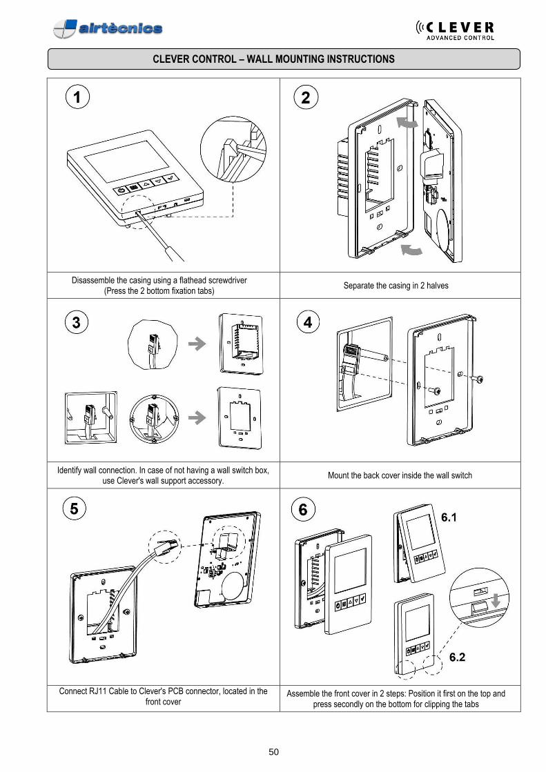
CLEVER CONTROL – WALL MOUNTING INSTRUCTIONS
Disassemble the casing using a flathead screwdriver
(Press the 2 bottom fixation tabs) Separate the casing in 2 halves
Identify wall connection. In case of not having a wall switch box, use Clever's wall support accessory.
Mount the back cover inside the wall switch
Connect RJ11 Cable to Clever's PCB connector, located in the front cover
Assemble the front cover in 2 steps: Position it first on the top and press secondly on the bottom for clipping the tabs
51
HOW TO MANUFACTURE THE CABLES
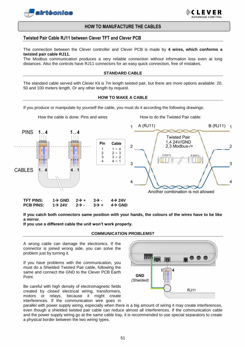
Twisted Pair Cable RJ11 between Clever TFT and Clever PCB
The connection between the Clever controller and Clever PCB is made by 4 wires, which conforms a twisted pair cable RJ11. The Modbus communication produces a very reliable connection without information loss even at long distances. Also the controls have RJ11 connectors for an easy quick connection, free of mistakes.
STANDARD CABLE
The standard cable served with Clever Kit is 7m length twisted pair, but there are more options available: 20, 50 and 100 meters length. Or any other length by request.
HOW TO MAKE A CABLE
If you produce or manipulate by yourself the cable, you must do it according the following drawings:
How the cable is done: Pins and wires How to do the Twisted Pair cable:
TFT PINS: 1 GND 2 + 3 - 4 24V PCB PINS: 1 24V 2 - 3 + 4 GND If you catch both connectors same position with your hands, the colours of the wires have to be like a mirror. If you use a different cable the unit won’t work properly.
COMMUNICATION PROBLEMS?
A wrong cable can damage the electronics. If the connector is joined wrong side, you can solve the problem just by turning it. If you have problems with the communication, you must do a Shielded Twisted Pair cable, following the same and connect the GND to the Clever PCB Earth Point. Be careful with high density of electromagnetic fields created by closed electrical wiring, transformers, motors or relays, because it might create interferences. If the communication wire goes in parallel with power supply wiring, especially when there is a big amount of wiring it may create interferences, even though a shielded twisted pair cable can reduce almost all interferences. If the communication cable and the power supply wiring go at the same cable tray, it is recommended to use special separators to create a physical border between the two wiring types.
52
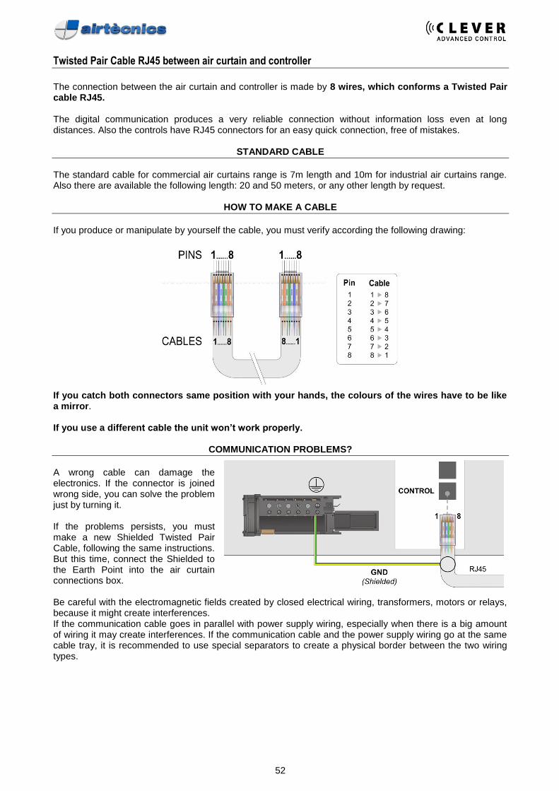
Twisted Pair Cable RJ45 between air curtain and controller
The connection between the air curtain and controller is made by 8 wires, which conforms a Twisted Pair cable RJ45. The digital communication produces a very reliable connection without information loss even at long distances. Also the controls have RJ45 connectors for an easy quick connection, free of mistakes.
STANDARD CABLE
The standard cable for commercial air curtains range is 7m length and 10m for industrial air curtains range. Also there are available the following length: 20 and 50 meters, or any other length by request.
HOW TO MAKE A CABLE
If you produce or manipulate by yourself the cable, you must verify according the following drawing:
If you catch both connectors same position with your hands, the colours of the wires have to be like a mirror. If you use a different cable the unit won’t work properly.
COMMUNICATION PROBLEMS?
A wrong cable can damage the electronics. If the connector is joined wrong side, you can solve the problem just by turning it. If the problems persists, you must make a new Shielded Twisted Pair Cable, following the same instructions. But this time, connect the Shielded to the Earth Point into the air curtain connections box. Be careful with the electromagnetic fields created by closed electrical wiring, transformers, motors or relays, because it might create interferences. If the communication cable goes in parallel with power supply wiring, especially when there is a big amount of wiring it may create interferences. If the communication cable and the power supply wiring go at the same cable tray, it is recommended to use special separators to create a physical border between the two wiring types.
53
TROUBLESHOOTING
CLEVER – Communication Issues
List of the most common troubles and solutions:
1. Cut and connect again the power supply? To see if it works again.
2. Search unit again? Basic Menu – Configuration – Scan.
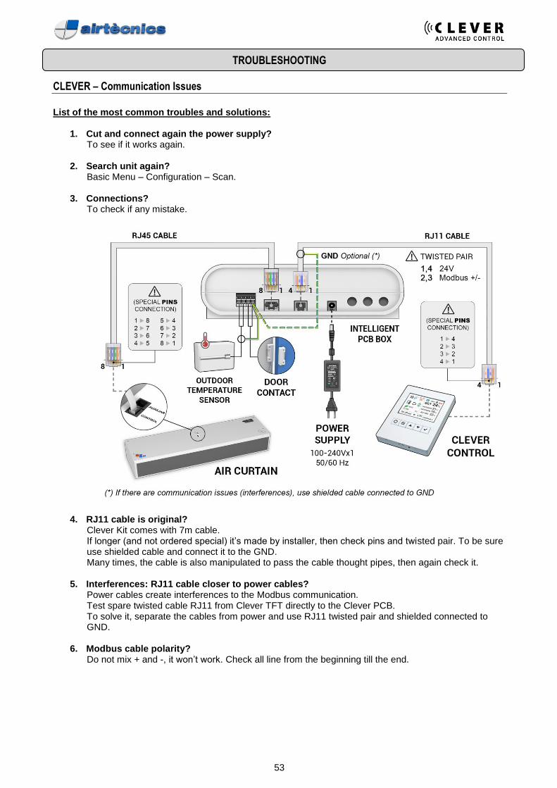
3. Connections? To check if any mistake.
4. RJ11 cable is original? Clever Kit comes with 7m cable. If longer (and not ordered special) it’s made by installer, then check pins and twisted pair. To be sure use shielded cable and connect it to the GND. Many times, the cable is also manipulated to pass the cable thought pipes, then again check it.
5. Interferences: RJ11 cable closer to power cables? Power cables create interferences to the Modbus communication. Test spare twisted cable RJ11 from Clever TFT directly to the Clever PCB. To solve it, separate the cables from power and use RJ11 twisted pair and shielded connected to GND.
6. Modbus cable polarity? Do not mix + and -, it won’t work. Check all line from the beginning till the end.

54
7. RTU1 port of Clever TFT?
RTU1 is dedicated exclusively Modbus port of Clever TFT to the first Clever PCB and between other Clever PCBs. All other connections (BMS, PLC, PC) will create communication errors.
8. BMS Modbus at RTU2? RTU2 is dedicated exclusively to communicate to BMS, PLC, PC systems. If you mix RTU1 and RTU2 you will have communication errors. BMS Modbus by default is 115200, if doesn’t work please check BMS has the same speed. If not change it at Basic Menu – Configuration.
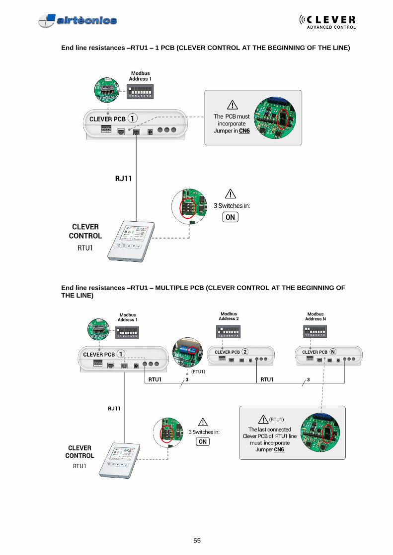
9. End line resistances? (switch and jumpers act as resistances)
Clever TFT should have always 3 switches in ON. Clever Modbus RTU1 requires the jumper CN6 at the last Clever PCB of the line. If only 1 unit already done by default. If Clever TFT is in the middle of the line, then you need jumpers at the beginning and at the end. If more than one PCB, then it should be done and checked by installer. BMS Modbus RTU2 requires the same but using Jumper CN5.
55
End line resistances –RTU1 – 1 PCB (CLEVER CONTROL AT THE BEGINNING OF THE LINE)
End line resistances –RTU1 – MULTIPLE PCB (CLEVER CONTROL AT THE BEGINNING OF THE LINE)
56
10. Only 1 Clever TFT at RTU1? Each group of PCBs connected by RTU1 can have maximum 1 Clever TFT.
11. Replace Clever TFT? All TFTs and PCBs should have same firmware version. If replace Clever TFT you should scan devices and sensors at Basic Menu – Configuration.
12. Red LED Clever PCB is OFF? If 24V at “OUT 24V 1A” then replace PCB. If 0V at “OUT 24V 1A” check power supply and transformer.
13. Repeated Modbus address? All devices should have different number. Never use address 0. If change number, scan again (Basic Menu – Configuration).
14. Modbus address over 12? By default Clever only search from 1 to 12. If over go to Basic Menu – Configuration and modify this search.
15. RTU1 Baud rate? Firmware below 5.13: Baud rate of RTU1 at 115200.
16. BMS, PLC, PC Baud rate? At Basic Menu - Configuration you can change Baud rate for BMS, PLC, PC.

57
CLEVER – Other Issues
CLEVER CONTROL
ERROR CHECK CAUSE / CONSEQUENCE
TFT lights are OFF
Red LED inside Clever PCB OFF
Check 24V power supply at terminal block "OUT 24V 1A" inside Clever PCB
Red LED inside Clever PCB ON
Check RJ11 cable (faulty or made on site wrongly) according to instructions
Air curtain starts alone or does nothing or wrong order of ventilation speeds
RJ45 cable from the Clever is connected to AUX instead of CONTROL RJ45 cable is faulty or made on site wrongly. Then please check instructions how to do it properly
Temperature unstable
Use and connect shielded cable to GND of the Clever PCB according to Clever manual to avoid interferences
Temperature difference
Calibrate temperature sensors at: Basic Menu - Parameters - Temperature – Calibration
Control inside cabinet
If Clever is inside a room with different temperature that air curtain, use an external extra room temperature
TFT buttons don't work
Remove and reconnect power supply
You can remove the RJ11 of the controller or cut Clever power supply
Configuration Main questions during installation
Manual or Automatic
Manual: user can modify ventilation, heating and temperature (depending on program) Automatic: user can only change temperature (no fan, no heating)
Door Contact
When door contact is not installed, then it works always like open door
Programs and Temperature Sensors
Programs are available depending on installed temperature sensors - By default Clever is configured at Auto P3 Comfort to work with: - Room temperature sensor of Clever TFT - Outside external temperature sensor If outside temperature sensor is not installed, then it will change automatically to basic program Auto P1 and give temperature sensor error message You can connect the required sensor or go to Basic Menu - Configuration - Search temperature sensors and validate to update them - If no temperature sensors, then Manual P1 Comfort by default (on option P2) - If only room temperature sensor, then Auto P1 by default (on option Manual P1,P2) An extra room temperature connected to TS3 has priority against Clever TFT, but can be modified at Advanced Menu - IN/OUT At some programs information not needed/used is not displayed
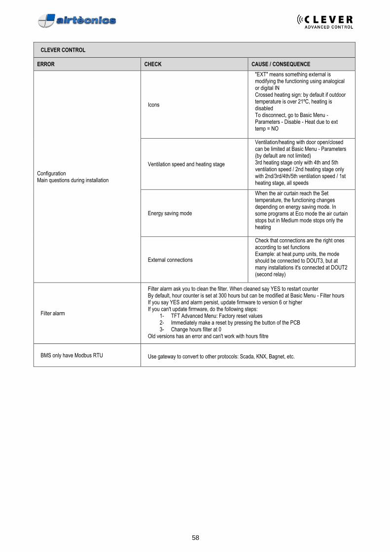
58
CLEVER CONTROL
ERROR CHECK CAUSE / CONSEQUENCE
Configuration Main questions during installation
Icons
"EXT" means something external is modifying the functioning using analogical or digital IN Crossed heating sign: by default if outdoor temperature is over 21ºC, heating is disabled To disconnect, go to Basic Menu - Parameters - Disable - Heat due to ext temp = NO
Ventilation speed and heating stage
Ventilation/heating with door open/closed can be limited at Basic Menu - Parameters (by default are not limited) 3rd heating stage only with 4th and 5th ventilation speed / 2nd heating stage only with 2nd/3rd/4th/5th ventilation speed / 1st heating stage, all speeds
Energy saving mode
When the air curtain reach the Set temperature, the functioning changes depending on energy saving mode. In some programs at Eco mode the air curtain stops but in Medium mode stops only the heating
External connections
Check that connections are the right ones according to set functions Example: at heat pump units, the mode should be connected to DOUT3, but at many installations it's connected at DOUT2 (second relay)
Filter alarm
Filter alarm ask you to clean the filter. When cleaned say YES to restart counter By default, hour counter is set at 300 hours but can be modified at Basic Menu - Filter hours If you say YES and alarm persist, update firmware to version 6 or higher If you can't update firmware, do the following steps:
1- TFT Advanced Menu: Factory reset values 2- Immediately make a reset by pressing the button of the PCB 3- Change hours filter at 0
Old versions has an error and can't work with hours filtre
BMS only have Modbus RTU
Use gateway to convert to other protocols: Scada, KNX, Bagnet, etc.