Clemson Automotive Electronics Research - Clemson Vehicular
24
Automotive EMC Workshop Capable and Reliable Electronic Systems Design Clemson Vehicular Electronics Laboratory Device Detection and Monitoring of Unintentional Radiated Emissions October 5, 2012 Todd Hubing Clemson University
Transcript of Clemson Automotive Electronics Research - Clemson Vehicular

Automotive EMC Workshop
Capable and Reliable Electronic Systems
Design
Clemson Vehicular Electronics Laboratory
Device Detection and Monitoring of Unintentional Radiated Emissions
October 5, 2012
Todd Hubing Clemson University

Clemson Vehicular Electronics Laboratory - 2012
CVEL Core Capabilities
2
Design for Electromagnetic Compatibility
Design for Reliability
EM Modeling of Components and Systems
Analysis of Unintentional EM Emissions

EMC Requirements and Key Design Considerations
Radiated Emissions Radiated Susceptibility
Transient Immunity
Electrostatic Discharge
Bulk Current Injection
• 1 HF GND • Risetime Control • Filtered I/O • Adequate
Decoupling • Balance Control
• 1 HF GND • Filtered I/O • Adequate
Decoupling • Balance Control
• LF Current Path Control
• Chassis GND on board
• Filtered I/O • Adequate
Decoupling
• LF Current Path Control
• Chassis GND on board
• Filtered I/O • Adequate
Decoupling
• 1 HF GND • Chassis GND on
board • Filtered I/O • Adequate
Decoupling • Balance Control
3
CVEL is the only U.S. laboratory to guarantee that the components they design will meet all automotive EMC requirements.
Clemson Vehicular Electronics Laboratory - 2012
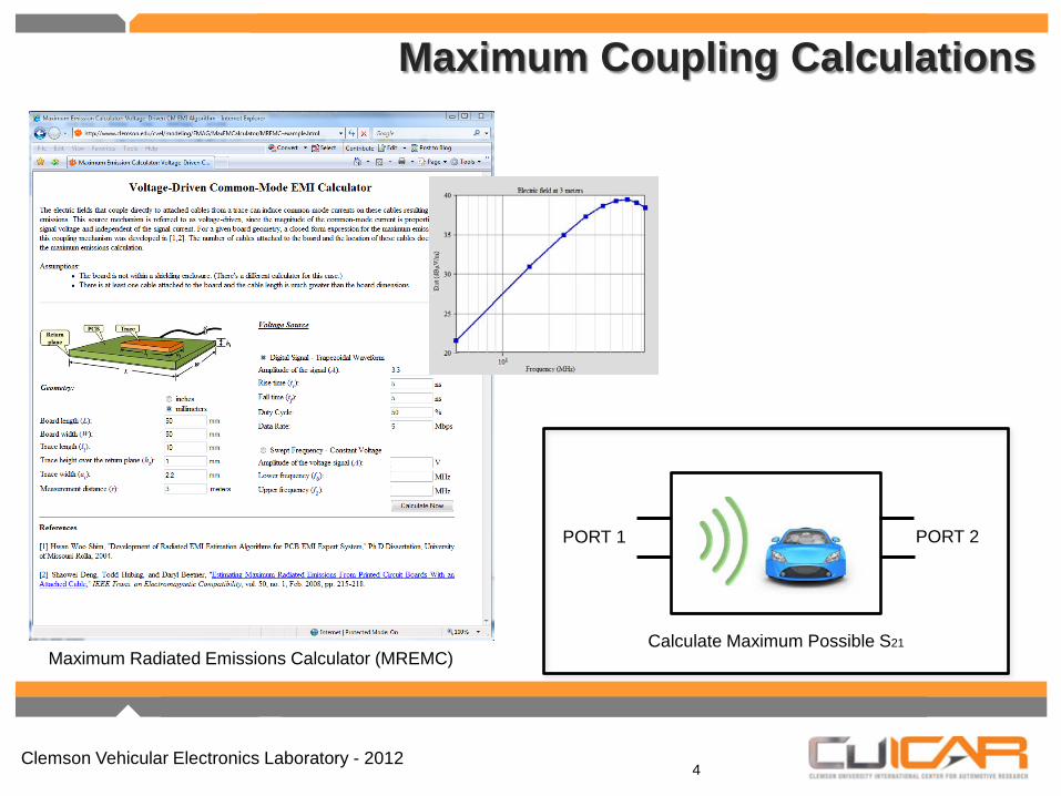
Maximum Coupling Calculations
4
PORT 1 PORT 2
Calculate Maximum Possible S21 Maximum Radiated Emissions Calculator (MREMC)
Clemson Vehicular Electronics Laboratory - 2012
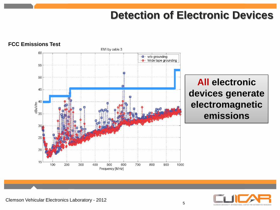
FCC Emissions Test
All electronic devices generate electromagnetic
emissions
Detection of Electronic Devices
5

Clemson Vehicular Electronics Laboratory - 2012
Typical Field Strengths
FCC Class A Device at 30 m ~30 µV/m
FCC Class B Device at 30 m ~10 µV/m
These field strengths are readily detectable and can be much stronger than fields from
intentional transmitters located further away.
Detection of Electronic Devices
6

Clemson Vehicular Electronics Laboratory - 2012
Detecting unintentional emissions from electronic devices is simply a matter of recognizing the desired signal when it is buried in the “noise” from hundreds of other sources (both intentional and unintentional).
There is ample signal strength to detect these devices!
Detection of Electronic Devices
7

Clemson Vehicular Electronics Laboratory - 2012
Detection of Electronic Devices
8
► AM/FM Demodulation ► Observation of Side Bands ► Short Term FFT ► Frequency Domain Signature ► Time Domain Signature ► Wavelet Filtering ► Singularity Expansion Method ► Combinations of the above
Techniques developed to identify and trace sources of EMI
Clemson Vehicular Electronics Laboratory - 2012
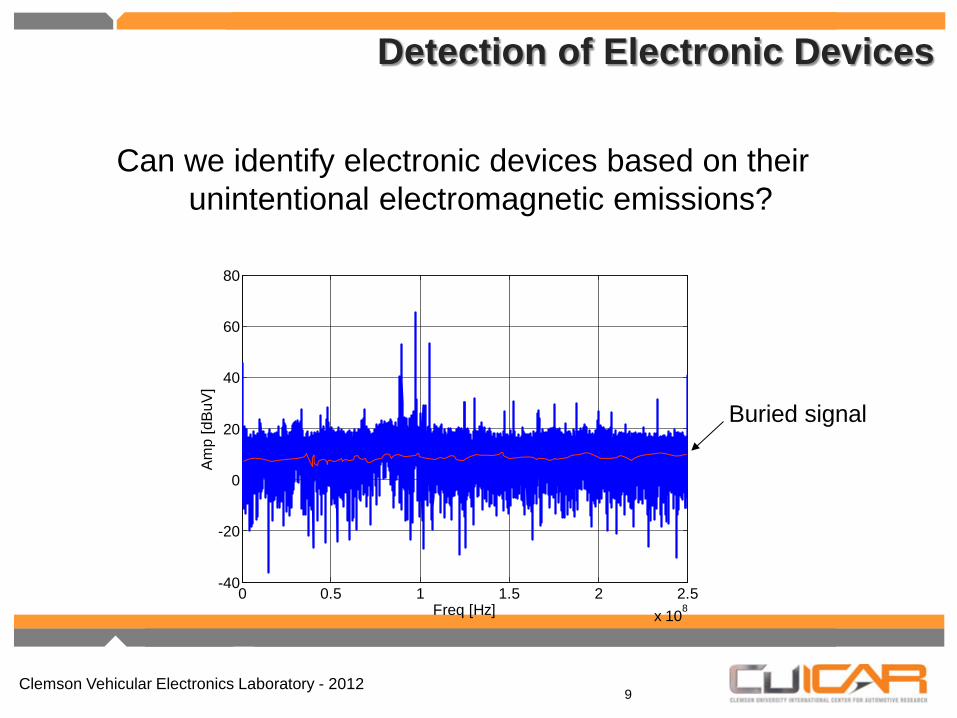
Can we identify electronic devices based on their unintentional electromagnetic emissions?
0 0.5 1 1.5 2 2.5x 10⁸
-40
-20
0
20
40
60
80
Freq [Hz]
Am
p [d
BuV
]
Buried signal
Detection of Electronic Devices
9
Clemson Vehicular Electronics Laboratory - 2012
Can Devices Be Uniquely Identified?
10
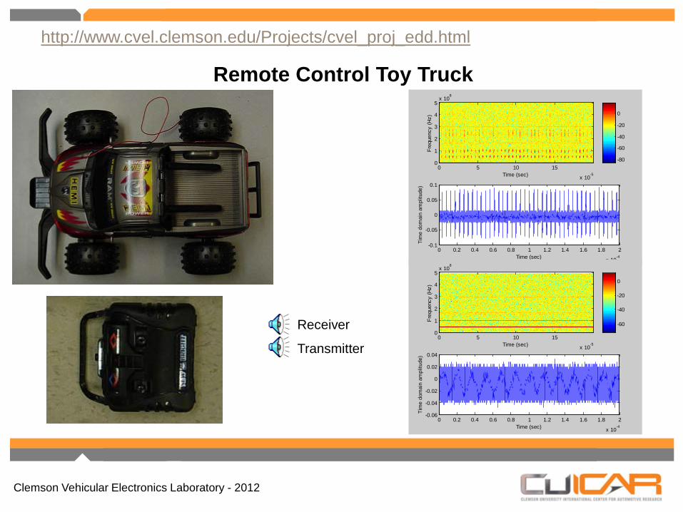
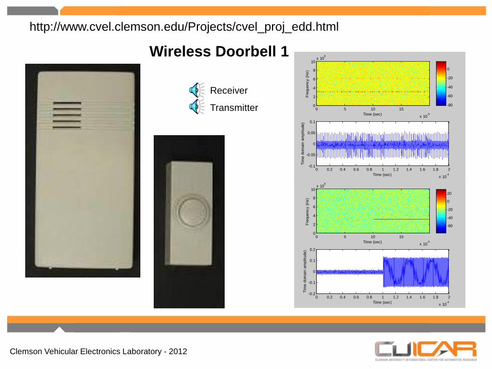
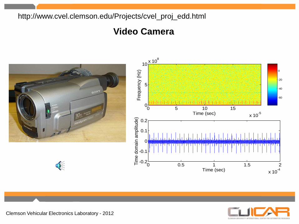
Radiated emissions were recorded from a variety of radio receivers used in IEDs.
Results were analyzed by:
Emission characteristics were used to build an instrument capable of automatically detecting and identifying emissions.
Extracting characteristics of emissions in both the time and frequency domain.
Re-sampling high-frequency electromagnetic recordings at audio frequencies to demonstrate unique characteristics of signals.
Clemson Vehicular Electronics Laboratory - 2012
-80
-60
-40
-20
0
Time (sec)
Freq
uenc
y (H
z)
0 5 10 15
x 10-5
0
1
2
3
4
5x 10
8
0 0.2 0.4 0.6 0.8 1 1.2 1.4 1.6 1.8 2
x 10-4
-0.1
-0.05
0
0.05
0.1
Time (sec)
Tim
e do
mai
n am
plitu
de)
Remote Control Toy Truck
Receiver
Transmitter
-60
-40
-20
0
Time (sec)
Freq
uenc
y (H
z)
0 5 10 15
x 10-5
0
1
2
3
4
5x 10
8
0 0.2 0.4 0.6 0.8 1 1.2 1.4 1.6 1.8 2
x 10-4
-0.06
-0.04
-0.02
0
0.02
0.04
Time (sec)Ti
me
dom
ain
ampl
itude
)
http://www.cvel.clemson.edu/Projects/cvel_proj_edd.html
Clemson Vehicular Electronics Laboratory - 2012
-80
-60
-40
-20
0
Time (sec)
Freq
uenc
y (H
z)
0 5 10 15
x 10-5
0
2
4
6
8
10x 10
8
0 0.2 0.4 0.6 0.8 1 1.2 1.4 1.6 1.8 2
x 10-4
-0.1
-0.05
0
0.05
0.1
Time (sec)
Tim
e do
mai
n am
plitu
de)
Wireless Doorbell 1
-60
-40
-20
0
20
Time (sec)
Freq
uenc
y (H
z)
0 5 10 15
x 10-5
0
2
4
6
8
10x 10
8
0 0.2 0.4 0.6 0.8 1 1.2 1.4 1.6 1.8 2
x 10-4
-0.2
-0.1
0
0.1
0.2
Time (sec)Ti
me
dom
ain
ampl
itude
)
Receiver
Transmitter
http://www.cvel.clemson.edu/Projects/cvel_proj_edd.html

Clemson Vehicular Electronics Laboratory - 2012
-60
-40
-20
0
Time (sec)
Freq
uenc
y (H
z)
0 5 10 15
x 10-5
0
2
4
6
8
10x 10
8
0 0.2 0.4 0.6 0.8 1 1.2 1.4 1.6 1.8 2
x 10-4
-0.06
-0.04
-0.02
0
0.02
0.04
Time (sec)
Tim
e do
mai
n am
plitu
de)
Wireless Doorbell 2
-60
-40
-20
0
20
Time (sec)
Freq
uenc
y (H
z)
0 5 10 15
x 10-5
0
2
4
6
8
10x 10
8
0 0.2 0.4 0.6 0.8 1 1.2 1.4 1.6 1.8 2
x 10-4
-0.2
-0.1
0
0.1
0.2
Time (sec)Ti
me
dom
ain
ampl
itude
)
Receiver
Transmitter
http://www.cvel.clemson.edu/Projects/cvel_proj_edd.html

Clemson Vehicular Electronics Laboratory - 2012
-80
-60
-40
-20
0
Time (sec)
Freq
uenc
y (H
z)
0 5 10 15
x 10-5
0
1
2
3
4
5x 10
8
0 0.2 0.4 0.6 0.8 1 1.2 1.4 1.6 1.8 2
x 10-4
-0.1
-0.05
0
0.05
0.1
Time (sec)
Tim
e do
mai
n am
plitu
de)
Wireless Phone
Receiver
http://www.cvel.clemson.edu/Projects/cvel_proj_edd.html

Clemson Vehicular Electronics Laboratory - 2012
Time (sec)
Freq
uenc
y (G
Hz)
0 2 4 6 8 10 12 14 16 18
x 10-5
1
0.5
0
0 0.5 1 1.5 2
x 10-4
-0.4
-0.2
0
0.2
0.4
0.6
Time (sec)
Vol
tage
(vo
lt)
Digital Camera http://www.cvel.clemson.edu/Projects/cvel_proj_edd.html
Clemson Vehicular Electronics Laboratory - 2012
Video Camera
-60
-40
-20
0
Time (sec)
Freq
uenc
y (H
z)
0 5 10 15x 10-5
0
5
10 x 108
0 0.5 1 1.5 2x 10⁻⁴
-0.2
-0.1
0
0.1
0.2
Time (sec)
Tim
e do
mai
n am
plitu
de)
http://www.cvel.clemson.edu/Projects/cvel_proj_edd.html

Clemson Vehicular Electronics Laboratory - 2012
Filtering of Noise
Toy Truck
Reference
In noisy environment
Processed representation of reference
Filtered representation of signal in noisy environment
Clemson Vehicular Electronics Laboratory - 2012
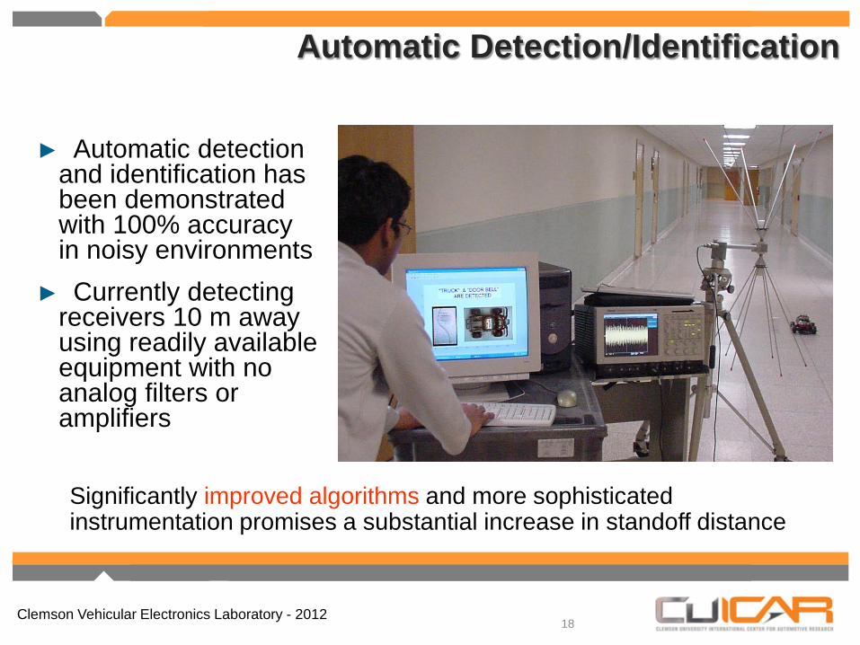
Automatic Detection/Identification
18
► Automatic detection and identification has been demonstrated with 100% accuracy in noisy environments
► Currently detecting receivers 10 m away using readily available equipment with no analog filters or amplifiers
Significantly improved algorithms and more sophisticated instrumentation promises a substantial increase in standoff distance

Clemson Vehicular Electronics Laboratory - 2012
Our latest detection algorithms are able to recognize the presence of signals that are deeply buried in the noise from other sources, even when those sources are operating at the same frequency.
Automatic Detection/Identification

Clemson Vehicular Electronics Laboratory - 2012
Electronic System Failure Prediction/Detection
20
Monitor emissions to look for specific failure indicators.
Monitor emissions to look for any departure from normal.
Two approaches to failure prediction/detection
Analogous to listening for engine knock or wheel bearing whine in an automobile
Analogous to hearing a strange noise coming from the engine
Clemson Vehicular Electronics Laboratory - 2012
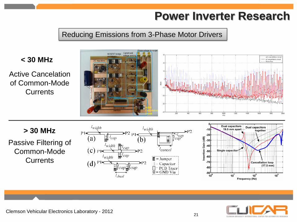
Power Inverter Research
21
Active Cancelation of Common-Mode
Currents
Passive Filtering of Common-Mode
Currents
< 30 MHz
> 30 MHz
Reducing Emissions from 3-Phase Motor Drivers

Clemson Vehicular Electronics Laboratory - 2012
Identifying MOSFET and IGBT Failures Before They Occur
22
PWM Switching Waveform (Low-side Drain Voltage) of a Power Inverter MOSFET

Clemson Vehicular Electronics Laboratory - 2012
Identifying MOSFET and IGBT Failures Before They Occur
23
Pole Locations Corresponding to Low-Side Oscillation
Application of Matrix Pencil Method with Pre-Conditioning
Clemson Vehicular Electronics Laboratory - 2012
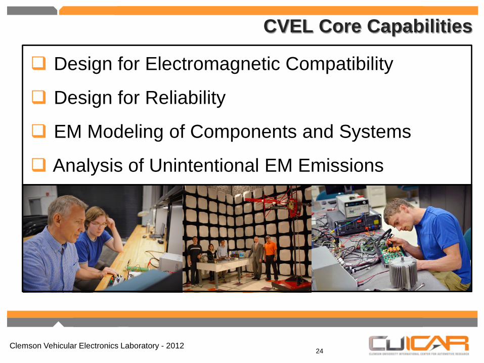
CVEL Core Capabilities
24
Design for Electromagnetic Compatibility
Design for Reliability
EM Modeling of Components and Systems
Analysis of Unintentional EM Emissions