Clearwater Spas SPA MANUAL
56
Clearwater Spas SPA MANUAL Resort Series | Beachcraft Series | XS Series P.O. Box 2140 | Woodinville, WA 98072 | www.clearwaterspas.com spa manual Clearwater Spas, US/Canada, 1.1.14 relax | refresh | renew
-
Upload
vuongtuyen -
Category
Documents
-
view
223 -
download
1
Transcript of Clearwater Spas SPA MANUAL

Clearwater Spas
SPA MANUALResort Series | Beachcraft Series | XS Series
P.O. Box 2140 | Woodinville, WA 98072 | www.clearwaterspas.com
spa manual Clearwater Spas, US/Canada, 1.1.14
relax | refresh | renew

2
“We reserve the right to improve our product without notice”
Copyright © Clearwater Spas, 2014. All rights reserved. Specifications may change without notice. International products may be configured differently to meet local electrical requirements. [Copyright © trademark 1976 Clearwater Spas™]
relax | refresh | renew
3
TABLE OF CONTENTS
5 INTRODUCTION 5 ICON Key
6 IMPORTANT SAFETY INSTRUCTIONS 6 Read and Follow All Instructions
8 STEPS FOR A SUCCESSFUL INSTALLATION 8 Delivery 9 Site Selection and Preparation 9 Installation – Placing Your Spa 11 Electrical Hook-Up Requirements 13 Filling Your Spa
14 TOPSIDE CONTROL - TURNING ON YOUR SPA 14 Topside Control Button Reference Display, TP600 16 Topside Control Button Reference Display, TP950 &TP800
31 WATER PURITY & FILTRATION 31 Keeping The Water Clean 31 Spa Chemistry 101 33 How To Use the Chemicals 34 Usage Definitions 34 Starting A Chemical Maintenance Program 36 Filtration 37 Ozone Generator 38 Salt System with ISIS Control Panel 40 Salt System with in.clear / Gecko Control Panel
42 JETS 42 Types Of Jets 43 Jet, Air and Waterfall Controls 43 Cleaning The Rotating Jets 44 Jet Removal

4
44 MAINTENANCE 44 Spa Light 44 Pillows 44 Spa Skirt 44 The Shell 44 Spa Cover 45 Winterizing 46 Draining The Spa 48 Energy Efficiency Green Technology
49 APPENDIX A 49 Troubleshooting 49 System Trouble 49 Controls 50 Pumps 50 Jets 50 Water 52 FAQ’s - Frequently Asked Questions 55 Warranty

5
INTRODUCTION
Congratulations on your purchase of a new Clearwater spa! Your Clearwater spa is designed and manufactured with the finest com-ponents available and is engineered with comfort, low maintenance, and durability in mind.
You will enjoy your spa for several years to come if you are diligent with the care and maintenance of your spa. This manual will help you to determine the best way to take care of your spa based on the amount of use and the type of environment your spa is installed.
It is very important for you to read the entire manual before at-tempting to use your spa. Contained in this manual are important maintenance and start-up procedures as well as safety precautions that must be followed to ensure the prolonged life of your spa and the safety of the people using the spa. Failure to follow start-up pro-cedures may damage your unit and void your warranty.
Please feel free to call your local Clearwater Spas dealer if you have any further questions after reading this manual. We hope you enjoy many years of fun and relaxation in your new Clearwater spa.
ICON Key
The Icon key on the left defines the type of information boxes that will appear throughout the manual. The boxes highlight helpful in-formation that contains useful tips or warnings that apply to the use and care of your spa.
Warning!
Safety Tip
Key Point
ICON KEY

6
Safety Warning!
SAFETY FIRSTIMPORTANT SAFETY INSTRUCTIONS!
READ AND FOLLOW ALL INSTRUCTIONS.SAVE THESE INSTRUCTIONS.
When installing and using this electrical equipment it is recom-mended that a licensed and bonded electrician perform the work. Basic safety precautions should always be followed, including the following:
• A pressure wire connector is provided on the outside of the control box to permit the connection of a solid copper bonding wire between the spa and any metal equipment, metal enclosures of electrical equipment, metal water pipe or conduit within 5 feet of the spa as needed to comply with local requirements.
• A green colored terminal (or a wire connector marked “G”, “GR”, “Ground”, or “Grounding”) is provided. To reduce the risk of electric shock, connect this terminal to the grounding terminal of your electric service or supply panel with a continuous green insulated copper wire equivalent to the circuit conductor supplying this equipment.
• The electrical supply must include a suitably rated Ground Fault Interrupter Circuit to open all underground supply conductors to comply with section 422-20 of the National Electrical Code. ANSI/NFPA 70-1987. The power supply cut off must be readily accessible to the spa occupant, but installed at least 5 feet from spa water.
• Test the performance of the GFCI according to manufac- turers recommendations. If the GFCI does not perform correctly, there may be a ground current flowing indicating the possibility of electric shock. Disconnect the power until the fault has been identified and corrected.
• DANGER –RISK OF ELECTRIC SHOCK. Install at least 5 feet from all metal surfaces.
• DANGER – RISK OF ELECTRIC SHOCK. Do not permit any electric appliance such as a light, telephone, radio or television within 5 feet of a spa or hot tub.
• WARNING –RISK OF CHILD DROWNING. Extreme caution must be exercised to prevent unauthorized access by children. To avoid accidents, ensure that children cannot use a spa or hot tub unless they are supervised at all times.
ElectricalWarning!
ElectricalWarning!

7
• DANGER – To reduce risk of injury, do not remove suction fittings.
• Installation should provide drainage of the electrical equipment area to prevent electrical shortage.
• Store all chemicals in a cool dry area and keep out of children’s reach.
• To reduce the risk of injury: A. Spa heat can cause hyperthermia and unconsciousness! The water in a spa or hot tub should never exceed 104° F (40° C). Water temperatures between 100° F (38° C) and 104° F (40° C) are considered safe for a healthy adult. Lower water tem- peratures are recommended for extended use (exceeding 10 –15 minutes) and for young children.
B. Since excessive water temperatures have a high potential for causing fetal damage during the early months of pregnancy, pregnant or possibly pregnant women should limit water temperatures to 100° F (38° C).
• The use of alcohol, drugs, or medication before or during spa or hot tub use may lead to unconsciousness with the possibility of drowning.
• Persons suffering from obesity or with a medical history of heart disease, low or high blood pressure, circulatory system problems or diabetes should consult a physician before using a spa or hot tub.
• Persons using medication should consult a physician before using a spa or hot tub since some medication may induce drowsiness while other medication may affect heart rate, blood pressure, and circulation.
• Before entering a spa, the user should measure the water temperature since the tolerance of water temperature- regulating devices varies.
WARNINGPREVENT DROWNING 1. SUPERVISE CHILDREN AT ALL TIMES. 2. ATTACH SPA COVER AFTER EACH USE. 3. SPA HEAT CAN CAUSE HYPERTHERMIA AND UNCONSCIOUSNESS. 4. SPA HEAT IN CONJUNCTION WITH ALCOHOL, DRUGS, OR MEDICATION CAN CAUSE UNCONSCIOUSNESS.
PREVENT ELECTROCUTION 1. NEVER PLACE ANY ELECTRIC APPLIANCE WITHIN 5 FEET OF SPA.
NOTE: THIS MARKING IS TO BE REMOVED ONLY BY THE CUSTOMER.
!r
Safety Warning!

8
STEPS FOR A SUCCESSFUL INSTALLATION:
1. PREPARING FOR YOUR SPA Prior to receiving your new spa, you will need to prepare an area to install the spa. You will need to arrange to have your spa placed in your desired loca-tion and the connection of the electrical circuits. In most cities, permits are required for the installation of electrical circuits.
Review the path that your spa will take through your property along with the size of the spa to ensure you have enough clearance. If there are stairs or other ob-stacles, the spa will have to travel over to get to the site, additional clearances may be required.
We have listed some key points to installing your spa that will help eliminate some of the unforeseeable situations that could occur.
• Avoid installing too close to a building or structure. • Leave enough room around all sides to allow access to service panels. • Install on a load bearing, level platform. • Do not install less than 5 feet from ground conductors. • Use non-conductive conduit for all wiring. • If installing below a deck surface, leave enough room to access and remove service panels.
We recommend a level 4” thick concrete pad if you are installing on land (ver-sus deck or platform). The dimensions of the pad should be at least the out-side dimension of the spa. You should also accommodate for steps or other items around the spa. Allow a few days for curing the cement when calculat-ing your scheduled delivery date.
Balconies and upper decks are not recommended for spa installations, but if you choose to do so, keep in mind that a large filled spa with 6 people can weigh as much as three tons. Balconies and decks must be constructed to current state and local building codes and must support at least 100 pounds per square foot.
If you are building a deck around the spa, be sure that the deck does not cover any of the service panels to the spa. If you are building stairs for getting up to the spa, it is recommended that they be installed in such a way that they can be moved out of the way if entrance to the service panels is required.
The most obvious thing to remember is to plan your installation in a loca-tion where it will be easy to move from the delivery truck to the location site. Spas are typically transported on a mover’s dolly lying on their side. Check for adequate gate clearance and remove any fence panels if necessary to allow access to the installation site.
Importantinstallationhighlights!

9
2. SITE SELECTION AND PREPARATIONThe location of your hot tub is entirely up to you. Carefully read these instructions for various ideas of locations that your new hot tub may be placed.
By the time you have made your spa pur-chase, you probably have a spot already picked out. Prior to the spa delivery, please verify the following:
• Always place the spa on a compacted and level surface. The best surface is a level concrete pad. A spa, full of water, can weigh a great deal. Please ensure the spot can support the weight.
• Make sure to level your spa before filling it. • Locate the equipment panel. The system pack, drain valve, owner’s manual and optional ozone generator are usually located all in the same area.
Be sure that the connections are tightened during draining. Water inside the system pack will cause the pack to fail and the breaker to trip.
• The panels, on all four sides, are removable. Be sure to have access on all four sides.• Be sure to have easy access to the circuit breaker in the sub panel (240 volt
models).• Never let water into the sub panel (240 volt models), or into the electrical outlet that your spa is plugged in to. Your 240 volt spa’s sub panel is rain
tight when installed correctly with the door closed.
3. INSTALLATION - PLACING YOUR SPAOutdoor and patio installationTo position the spa correctly in your backyard is very important. The reason is your spa’s warranty. The warranty on a spa is voided if the site is not level. If you install your hot tub outdoors, a concrete pad is the best method for a stable and level surface. The concrete pad should be four inches thick. Your spa may be installed on a deck, providing the load rating can handle a full spa with people in it.
Deck installation When placing the spa on a deck, please ensure the maximum load capacity of the deck. Consult a qualified deck builder or structural engineer before you place the hot tub on an elevated deck or indoors. To de-termine the weight of your hot tub, please refer to the specifications on the website. This weight must not exceed the structural weight of the deck.

10
Indoor installation When installing a spa indoors, there are some special considerations. The combination of heat and moisture will accumulate on the floor and surround-ing the spa. The flooring material needs to provide a grip when wet. The location also needs proper drainage to prevent water build-up around the spa. When building a room for your spa, it is best to have a floor drain in-stalled. The humidity of a room with a spa can become a problem if there is not enough proper ventilation. Otherwise, problems such as dry rot, mildew or other problems may occur.
Ground preparation Your spa has been engineered to rest on a variety of surfaces. The insulated spa floor base gives you the ability to find the perfect place. A concrete slab is the best for long term. There are other options available as long as the surface is level prior to delivery. The alternatives are 5/8 minus crushed packed rock, or a deck that is rated for the load.
Brick pavers
Cement
Decorative cement, stained
Packed/crushed gravel: 5/8” minus
Stone, slate, granite
Decking: wood, synthetic
Decorative cement & bricks
Marble, travertine
When placing a spa on crushed rock, the easiest way to maintain its form is to build a frame and fill it with the crushed packed rock. Remember, if the spa is placed on grass or dirt, debris will get inside the spa as the users enter and exit.
It is incredibly important to the operation and the draining of the tub for the tub to be level once it is installed. Failure to have the spa level prior to adding water can affect the warranty.

11
4. ELECTRICAL HOOK-UP REQUIREMENTS - 240VRemoving spa panels
1. Remove the plastic ‘tap-cap’ decorative screw head covers from screws on access spa panel.
2. Unscrew the screws from the access spa panel.
3. Remove the spa panel for access to spa com-ponents. Reverse these steps to attach the spa panel.
Electrical connections by licensed personnelTo ensure you will have an opportunity to use your hot tub soon after delivery, it is very important that the required electrical service has been installed.
IMPORTANT: Electrical connections must be made by qualified, licensed personnel. Please contact a licensed residential electri-cian for these services.
All models require a 50 amp single phase, 240 volt circuit breaker in the main electrical service panel. NOTE: WE RECOMMEND THAT A SUB PANEL BE USED TO SUPPLY POWER AND PROTECT THE SPA. All 240 volt Clearwater spas must be wired in accordance with appli-cable local electrical codes, and all electrical work must be done by a licensed electrician. A licensed electrician should install a four-wire electrical service (two line voltages, one neutral, one ground) from the main electrical service panel to the sub-panel, and from the sub-panel to the spa per the appropriate wiring diagram as illustrated below. The grounding conductor must be at least #6 AWG. Your electrician should mount the sub-panel in the vicinity of the spa but it should not be closer than five (5) feet from the spa’s water edge (NEC 680-38 to 41-A-3).
WARNING: Removing or bypassing the GFCI breakers in the sub panel at any time will result in an unsafe spa and will void the warranty.
WIRE SPECIFICATION NOTE: Long electrical runs may require a larger gauge feed wire than stated. We recommend that a maximum voltage drop of 3% be used when calculating the larger wire size.
Refer to the Wiring Diagrams (figure 1-1) for the electrical require-ments of the 240 volt models.
Do not turn on power to the spa when the tub is not filled.
The closer you locate the spa
to the main service panel,
the less money you will have to spend on wire.
Wire can become expensive if you
run long lengths.
Always shut offpower at thesource when
working with anyelectrical power!!Failure to do this
could result inserious injury or
even death!

12
ELECTRICAL REQUIREMENTS - 240V (cont.)
IMPORTANT: Electrical connections must be made by qualified, licensed personnel. Please contact a licensed residential electrician for these services.
Figure 1-1240 volt wiring configuration from the house to the spa

13
FILLING YOUR SPA THROUGH THE FILTER CHAMBERBefore you begin to fill your spa, it is advisable to have your water tested for hardness (water rich in calcium and mineral content). Wells usually contain harder water than urban water supplies. Mineral and metal imbalances in your water can shorten the life of the equip-ment in your spa. Contact your local dealer for proper water analysis.
We recommend that you purchase a high quality “Water Test Kit” for checking pH and sanitizer levels. Test the water daily until your “user load” is determined.
Make sure there is no dirt or sediment at the bottom of the tub and that there is nothing inside the filter compartment before filling with water. Filling the spa through the filter housing will help to pre-vent air locks (trapped pockets of air) in pumps on start up.
Identify your filter housing and fill as shown:
p TOP-ACCESS DUAL-FILTER HOUSING WITH TURBINE VANE FILTER COVER
p TOP-ACCESS SINGLE-FILTER HOUSING
1. Place your garden hose into the filter housing. This will ensure that air bubbles are removed from the lines while you fill the spa.
2. Turn the water on so that most of the water enters through the filter chamber.
3. Fill the water to the proper level – half way up the filter housing, just below the head pillow or just under the neck jets as shown in pictures above.
IMPORTANT!Do not fill your tub with water
from your hot water heater!
IMPORTANT!Improperly
balanced water may damage yourspa and void your warranty! Do not fill your tub with water from your
hot water heater!

14
TOPSIDE CONTROLS: TP600TURNING ON YOUR SPA
PUMP 1
PUMP 2 LIGHT
FLIP HEATLIGHTPUMP 1 PUMP 2
WARM
COOL
PUMP 1
PUMP 2 LIGHT
FLIP HEATLIGHTPUMP 1 PUMP 2
WARM
COOL
Figure 1: TP600 control panel, 6-button (2 pumps) Spa Models: XS Series Signature Package, U.S./Canada/European
PUMP 1
LIGHT
FLIP HEATLIGHTPUMP 1
WARM
COOL
PUMP 1
LIGHT
FLIP HEATLIGHTPUMP 1
WARM
COOL
Figure 2: TP600 control panel, 5-button (1 pump)Spa Models: XS Series Gold Package, U.S./Canada/European
Start UpWhen the GFCI for the spa is switched on to supply power, a startup sequence of numbers will appear on the display. If no button is pressed, LINK will appear after the startup sequence. Press any button to link the panel with the system.
The spa will enter Priming Mode. After Linking, press the Jets Button(s) to turn the pumps on and off to verify that all air is purged from the plumbing, partic-ularly the plumbing associated with the heater. If the spa uses a circulation pump, the Light Button turns the Circ Pump on an off during Priming Mode. Priming Mode will end automatically in 4 minutes. Pressing a Temperature Button will exit Priming Mode manually. When Priming Mode ends, Pump 1 low will start, if no circ pump is present, however the water temperature will not appear for a minute or so. Once the water temperature is recognized by the system, and if it is below the Set Temperature, the heater will start.
Basic OperationThe Up and Down buttons are often referred to as Temperature Buttons. Some panels only have a single Temperature Button. Press a Temperature Button once and the current Set Temperature will begin to flash on the LCD. (The Set Tem-perature and the actual water temperature are often different.) While the numbers are flashing, press a Temperature Button again to change the Set Temperature. Press-and-hold for faster adjustment. After the new Set Temperature stops flash-ing, in about 10 seconds, the actual temperature is displayed again and the new Set Temperature is programmed. The spa will now heat to the new Set Temperature as needed.

15
The Light Button turns the Spa Light on and off and is also used in conjunctions with the Temperature Button(s) to navigate the system menus.
ProgrammingRefer to the TP600 User Guide (40940) for detailed operation, programming and message instructions.
Navigating the deeper menu structure is done with only 2 or 3 buttons on the control panel. Pressing the Light button while the Set Temperature is flashing will enter the menus. Pressing Light after that will proceed through the menu choices. Pressing a Temperature Button while any menu item is showing will either edit it directly or begin an editing sequence.
Depending on the screen displayed, waiting between 10 and 30 seconds will allow the panel to return to normal operation and a display of spa status.
FiltrationThe system is factory-programmed with one filter cycle that will run in the evening (assuming the time-of-day is properly set) when energy rates are often lower. The filter time and duration are programmable. Refer to the TP600 User Guide (40940) for detailed instructions.
A second filter cycle can be enabled as needed.
Dual Temperature RangesThis system incorporates two temperature range settings with independent set temperatures. The High Range is indicated in the display and might be set be-tween 80°F and 104°F. The Low Range is indicated in the display and might be set between 50°F and 99°F. Low Range may be economical during non-use periods.
More specific temperature ranges, such as 50°F to 79°F for low range, or 90°F to 104°F for High Range, may determined by the manufacturer.
Ready and Rest ModesIf the filtration pump is a 2-Speed Pump 1, READY Mode will circulate water every 1/2 hour, using Pump 1 Low, in order to maintain a constant water temperature, heat as needed, and refresh the temperature display. This is known as “polling.”
REST Mode will only allow heating during programmed filter cycles. Since polling does not occur, the temperature display may not show a current temperature until the filtration pump has been running for a minute or two. READY/REST Mode may appear when Jets 1 is activated.
Complete ReferenceDownload the complete User Interface and Programming Guide at http://service.balboa-instruments.com/zz40940_download.zip
You may also download a programming guide athttp://www.clearwaterspas.com/product-resources

16
TOPSIDE CONTROLS: TP950, TP800TURNING ON YOUR SPA THE MAIN SCREEN
Figure 1: TP950 control panel Spa Model: Resort Series Signature Package, U.S./Canada/European
Figure 2: TP800 control panel (2 pumps) Spa Models: Beachcraft Series Signature Package, U.S./Canada
Figure 3: TP800 control panel (3 pumps) Spa Models: Beachcraft Series Signature Package, European
17
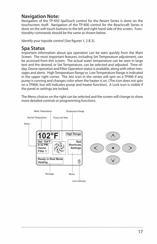
Navigation Note:Navigation of the TP-950 SpaTouch control for the Resort Series is done on the touchscreen itself. Navigation of the TP-800 control for the Beachcraft Series is done on the soft touch buttons to the left and right hand side of the screen. Func-tionality commands should be the same as shown below.
Identify your topside control (See figures 1, 2 & 3).
Spa StatusImportant information about spa operation can be seen quickly from the Main Screen. The most important features, including Set Temperature adjustment, can be accessed from this screen. The actual water temperature can be seen in large text and the desired, or Set Temperature, can be selected and adjusted. Time-of-day, Ozone operation and Filter Operation status is available, along with other mes-sages and alerts. High Temperature Range vs. Low Temperature Range is indicated in the upper right corner. The Jets Icon in the center will spin on a TP900 if any pump is running and changes color when the heater is on. (The icon does not spin on a TP800, but still indicates pump and heater function). A Lock icon is visible if the panel or settings are locked.
The Menu choices on the right can be selected and the screen will change to show more detailed controls or programming functions.
40985_F 12-08-112
Manufactured under one or more of these patents. U.S. Patents: 5332944, 5361215, 5550753, 5559720, 5,883,459, 6253227, 6282370, 6590188, 6976052, 6965815, 7030343, 7,417,834 b2,Canadian Patent: 2342614, Australian patent: 2373248 other patents both foreign and domestic applied for and pending. All material copyright of Balboa Water Group.
The Main Screen
Set: 104°F8:32 PMOzoneFilter 1
SpaShortcuts
Settings
High Range102°F
Ready in Rest ModeHeating
Spa Status Important information about spa operation can be seen quickly from the Main Screen.
The most important features, including Set Temperature adjustment, can be accessed from this screen.
The actual water temperature can be seen in large text and the desired, or Set Temperature, can be selected and adjusted.
Time-of-day, Ozone operation and Filter Operation status is available, along with other messages and alerts.
High Temperature Range vs. Low Temperature Range is indicated in the upper right corner.
The Jets Icon in the center will spin on a TP900 if any pump is running and changes color when the heater is on. (The icon does not spin on a TP800, but still indicates pump and heater function)
A Lock icon is visible if the panel or settings are locked.
The Menu choices on the right can be selected and the screen will change to show more detailed controls or programming functions.
Water Temperature
Messages
Desired Temperature
Temperature Range
Pump and Heat
Menus
Lock Indicator
Status
18
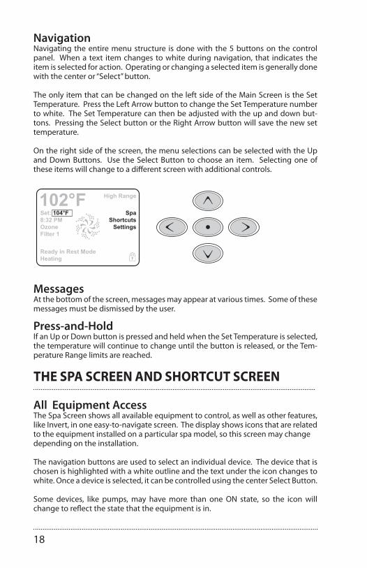
NavigationNavigating the entire menu structure is done with the 5 buttons on the control panel. When a text item changes to white during navigation, that indicates the item is selected for action. Operating or changing a selected item is generally done with the center or “Select” button.
The only item that can be changed on the left side of the Main Screen is the Set Temperature. Press the Left Arrow button to change the Set Temperature number to white. The Set Temperature can then be adjusted with the up and down but-tons. Pressing the Select button or the Right Arrow button will save the new set temperature.
On the right side of the screen, the menu selections can be selected with the Up and Down Buttons. Use the Select Button to choose an item. Selecting one of these items will change to a different screen with additional controls.
40985_F 12-08-113
Manufactured under one or more of these patents. U.S. Patents: 5332944, 5361215, 5550753, 5559720, 5,883,459, 6253227, 6282370, 6590188, 6976052, 6965815, 7030343, 7,417,834 b2,Canadian Patent: 2342614, Australian patent: 2373248 other patents both foreign and domestic applied for and pending. All material copyright of Balboa Water Group.
The Main ScreenNavigation Navigating the entire menu structure is done with the 5 buttons on the control panel.
When a text item changes to white during navigation, that indicates the item is selected for action.
Operating or changing a selected item is generally done with the center or “Select” button.
The only item that can be changed on the left side of the Main Screen is the Set Temperature. Press the Left Arrow button to change the Set Temperature number to white. The Set Temperature can then be adjusted with the up and down buttons. Pressing the Select button or the Right Arrow button will save the new set temperature.
On the right side of the screen, the menu selections can be selected with the Up and Down Buttons. Use the Select Button to choose an item. Selecting one of these items will change to a different screen with additional controls.
Set: 104°F8:32 PMOzoneFilter 1
SpaShortcuts
Settings
High Range102°F
Ready in Rest ModeHeating
MessagesAt the bottom of the screen, messages may appear at various times. Some of these messages must be dismissed by the user (see page 17).
Press-and-HoldIf an Up or Down button is pressed and held when the Set Temperature is selected, the temperature will continue to change until the button is released, or the Temperature Range limits are reached.
MessagesAt the bottom of the screen, messages may appear at various times. Some of these messages must be dismissed by the user.
Press-and-HoldIf an Up or Down button is pressed and held when the Set Temperature is selected, the temperature will continue to change until the button is released, or the Tem-perature Range limits are reached.
THE SPA SCREEN AND SHORTCUT SCREEN
All Equipment AccessThe Spa Screen shows all available equipment to control, as well as other features, like Invert, in one easy-to-navigate screen. The display shows icons that are related to the equipment installed on a particular spa model, so this screen may changedepending on the installation.
The navigation buttons are used to select an individual device. The device that is chosen is highlighted with a white outline and the text under the icon changes to white. Once a device is selected, it can be controlled using the center Select Button.
Some devices, like pumps, may have more than one ON state, so the icon will change to reflect the state that the equipment is in.
19
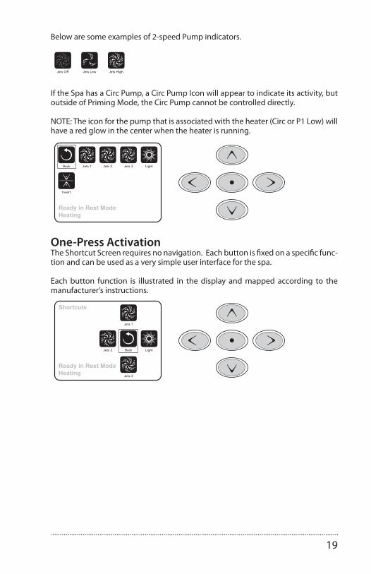
Below are some examples of 2-speed Pump indicators.
40985_F 12-08-114
Manufactured under one or more of these patents. U.S. Patents: 5332944, 5361215, 5550753, 5559720, 5,883,459, 6253227, 6282370, 6590188, 6976052, 6965815, 7030343, 7,417,834 b2,Canadian Patent: 2342614, Australian patent: 2373248 other patents both foreign and domestic applied for and pending. All material copyright of Balboa Water Group.
The Spa Screen and Shortcut ScreenAll Equipment Access The Spa Screen shows all available equipment to control, as well as other features, like Invert, in one easy-to-navigate screen. The display shows icons that are related to the equipment installed on a particular spa model, so this screen may change depending on the installation.
The navigation buttons are used to select an individual device. The device that is chosen is highlighted with a white outline and the text under the icon changes to white. Once a device is selected, it can be controlled using the center Select Button.
Some devices, like pumps, may have more than one ON state, so the icon will change to refl ect the state that the equipment is in. Below are some examples of 2-speed Pump indicators.
Jets HighJets LowJets Off
If the Spa has a Circ Pump, a Circ Pump Icon will appear to indicate its activity, but outside of Priming Mode, the Circ Pump cannot be controlled directly.
NOTE: The icon for the pump that is associated with the heater (Circ or P1 Low) will have a red glow in the center when the heater is running.
Ready in Rest ModeHeating
Back Jets 1 Jets 2 Jets 3 Light
Invert
One-Press Activation The Shortcut Screen requires no navigation. Each button is fi xed on a specifi c fuction and can be used as a very simple user interface for the spa.
Each button function is illustrated in the display and mapped according to the manufacturer’s instructions.
Ready in Rest ModeHeating
Shortcuts
Jets 3
Jets 2
Jets 1
LightBack
If the Spa has a Circ Pump, a Circ Pump Icon will appear to indicate its activity, but outside of Priming Mode, the Circ Pump cannot be controlled directly.
NOTE: The icon for the pump that is associated with the heater (Circ or P1 Low) will have a red glow in the center when the heater is running.
40985_F 12-08-114
Manufactured under one or more of these patents. U.S. Patents: 5332944, 5361215, 5550753, 5559720, 5,883,459, 6253227, 6282370, 6590188, 6976052, 6965815, 7030343, 7,417,834 b2,Canadian Patent: 2342614, Australian patent: 2373248 other patents both foreign and domestic applied for and pending. All material copyright of Balboa Water Group.
The Spa Screen and Shortcut ScreenAll Equipment Access The Spa Screen shows all available equipment to control, as well as other features, like Invert, in one easy-to-navigate screen. The display shows icons that are related to the equipment installed on a particular spa model, so this screen may change depending on the installation.
The navigation buttons are used to select an individual device. The device that is chosen is highlighted with a white outline and the text under the icon changes to white. Once a device is selected, it can be controlled using the center Select Button.
Some devices, like pumps, may have more than one ON state, so the icon will change to refl ect the state that the equipment is in. Below are some examples of 2-speed Pump indicators.
Jets HighJets LowJets Off
If the Spa has a Circ Pump, a Circ Pump Icon will appear to indicate its activity, but outside of Priming Mode, the Circ Pump cannot be controlled directly.
NOTE: The icon for the pump that is associated with the heater (Circ or P1 Low) will have a red glow in the center when the heater is running.
Ready in Rest ModeHeating
Back Jets 1 Jets 2 Jets 3 Light
Invert
One-Press Activation The Shortcut Screen requires no navigation. Each button is fi xed on a specifi c fuction and can be used as a very simple user interface for the spa.
Each button function is illustrated in the display and mapped according to the manufacturer’s instructions.
Ready in Rest ModeHeating
Shortcuts
Jets 3
Jets 2
Jets 1
LightBack
One-Press ActivationThe Shortcut Screen requires no navigation. Each button is fixed on a specific func-tion and can be used as a very simple user interface for the spa.
Each button function is illustrated in the display and mapped according to the manufacturer’s instructions.
40985_F 12-08-114
Manufactured under one or more of these patents. U.S. Patents: 5332944, 5361215, 5550753, 5559720, 5,883,459, 6253227, 6282370, 6590188, 6976052, 6965815, 7030343, 7,417,834 b2,Canadian Patent: 2342614, Australian patent: 2373248 other patents both foreign and domestic applied for and pending. All material copyright of Balboa Water Group.
The Spa Screen and Shortcut ScreenAll Equipment Access The Spa Screen shows all available equipment to control, as well as other features, like Invert, in one easy-to-navigate screen. The display shows icons that are related to the equipment installed on a particular spa model, so this screen may change depending on the installation.
The navigation buttons are used to select an individual device. The device that is chosen is highlighted with a white outline and the text under the icon changes to white. Once a device is selected, it can be controlled using the center Select Button.
Some devices, like pumps, may have more than one ON state, so the icon will change to refl ect the state that the equipment is in. Below are some examples of 2-speed Pump indicators.
Jets HighJets LowJets Off
If the Spa has a Circ Pump, a Circ Pump Icon will appear to indicate its activity, but outside of Priming Mode, the Circ Pump cannot be controlled directly.
NOTE: The icon for the pump that is associated with the heater (Circ or P1 Low) will have a red glow in the center when the heater is running.
Ready in Rest ModeHeating
Back Jets 1 Jets 2 Jets 3 Light
Invert
One-Press Activation The Shortcut Screen requires no navigation. Each button is fi xed on a specifi c fuction and can be used as a very simple user interface for the spa.
Each button function is illustrated in the display and mapped according to the manufacturer’s instructions.
Ready in Rest ModeHeating
Shortcuts
Jets 3
Jets 2
Jets 1
LightBack

20
THE SETTINGS SCREEN
Pressing a “Button”When instructions are given to “press a button” any of the following can be done:• Navigate to the desired item on any Screen. When the desired item is highlighted,
press the Select Button.• Press the button for that device while on the Shortcuts Screen, if the device is one
of the 4 functions available.
Programming, Etc.The Settings Screen is where all programming and other spa behaviors are con-trolled. This screen has several features that can be acted on directly. These fea-tures include Temp Range, Heat Mode, and Invert Panel. When one of these items is highlighted, the Select Button is used to toggle between two settings. All other menu items (with an arrow pointing to the right) go to another level in the menu.
Press-and-HoldIf an Up or Down button is pressed and held when an item in a Menu List is high-lighted, the list can be scrolled quickly from top to bottom. The scroll bar on the right side of the screen indicates the relative position of the highlighted item.
40985_F 12-08-115
Manufactured under one or more of these patents. U.S. Patents: 5332944, 5361215, 5550753, 5559720, 5,883,459, 6253227, 6282370, 6590188, 6976052, 6965815, 7030343, 7,417,834 b2,Canadian Patent: 2342614, Australian patent: 2373248 other patents both foreign and domestic applied for and pending. All material copyright of Balboa Water Group.
The Settings Screen
Programming, Etc. The Settings Screen is where all programming and other spa behaviors are controlled.
This screen has several features that can be acted on directly. These features include Temp Range, Heat Mode, and Invert Panel. When one of these items is highlighted, the Select Button is used to toggle between two settings.
All other menu items (with an arrow pointing to the right) go to another level in the menu.
Pressing a “Button” When instructions are given to “press a button” any of the following can be done:
• Navigate to the desired item on any Screen. When the desired item is highlighted, press the Select Button.
• Press the button for that device while on the Shortcuts Screen, if the device is one of the 4 functions available.
Settings
BackTemp RangeHeat ModeTime of DayFilter CyclesLight CycleInvert PanelLock
HighReady
Normal
Press-and-HoldIf an Up or Down button is pressed and held when an item in a Menu List is highlighted, the list can be scrolled quickly from top to bottom. The scroll bar on the right side of the screen indicates the relative position of the highlighted item in the list.
Dual Temperature Ranges (High vs. Low)This system incorporates two temperature range settings with independent set temperatures. The specifi c range can be selected on the Settings screen and is visible on the Main Screen in the upper right corner of the display.
These ranges can be used for various reasons, with a common use being a “ready to use” setting vs. a “vacation” setting. Each range maintains its own set temperature as programmed by the user. This way, when a range is chosen, the spa will heat to the set temperature associated with that range.
High Range can be set between 80°F and 104°F.
Low Range can be set between 50°F and 99°F.
More specifi c Temp Ranges may be determined by the Manufacturer.
Freeze Protection is active in either range.
Dual Temperature Ranges (High vs. Low)This system incorporates two temperature range settings with independent set temperatures. The specific range can be selected on the Settings screen and is vis-ible on the Main Screen in the upper right corner of the display.
These ranges can be used for various reasons, with a common use being a “ready to use” setting vs. a “vacation” setting. Each range maintains its own set temperature as programmed by the user. This way, when a range is chosen, the spa will heat to the set temperature associated with that range.
High Range can be set between 80°F and 104°F.Low Range can be set between 50°F and 99°F.More specific Temp Ranges may be determined by the Manufacturer.Freeze Protection is active in either range.

21
Heat Mode – Ready vs. RestIn order for the spa to heat, a pump needs to circulate water through the heater. The pump that performs this function is known as the “heater pump.”
The heater pump can be either a 2-speed pump (Pump 1) or a circulation pump. If the heater pump is a 2-Speed Pump 1, READY Mode will circulate water every 1/2 hour, using Pump 1 Low, in order to maintain a constant water temperature, heat as needed, and refresh the temperature display. This is known as “polling.”
REST Mode will only allow heating during programmed filter cycles. Since polling does not occur, the temperature display may not show a current temperature until the heater pump has been running for a minute or two.
While Pump 1 High can be turned on and off, Pump 1 Low will run until set tem-perature is reached, or 1 hour has passed.
Circulation Mode (See section under Pumps, for other circulation modes)If the spa is configured for 24HR circulation, the heater pump generally runs con-tinuously. Since the heater pump is always running, the spa will maintain set tem-perature and heat as needed in Ready Mode, without polling.
In Rest Mode, the spa will only heat to set temperature during programmed filter times, even though the water is being filtered constantly when in Circulation Mode.
40985_F 12-08-116
Manufactured under one or more of these patents. U.S. Patents: 5332944, 5361215, 5550753, 5559720, 5,883,459, 6253227, 6282370, 6590188, 6976052, 6965815, 7030343, 7,417,834 b2,Canadian Patent: 2342614, Australian patent: 2373248 other patents both foreign and domestic applied for and pending. All material copyright of Balboa Water Group.
The Settings Screen – ContinuedHeat Mode – Ready vs. RestIn order for the spa to heat, a pump needs to circulate water through the heater. The pump that performs this function is known as the “heater pump.”
The heater pump can be either a 2-speed pump (Pump 1) or a circulation pump.
If the heater pump is a 2-Speed Pump 1, READY Mode will circulate water every 1/2 hour, using Pump 1 Low, in order to maintain a constant water temperature, heat as needed, and refresh the temperature display. This is known as “polling.”
REST Mode will only allow heating during programmed fi lter cycles. Since polling does not occur, the temperature display may not show a current temperature until the heater pump has been running for a minute or two.
While Pump 1 High can be turned on and off, Pump 1 Low will run until set temperature is reached, or 1 hour has passed.
Circulation Mode (See Page 8, under Pumps, for other circulation modes)
If the spa is confi gured for 24HR circulation, the heater pump generally runs continuously. Since the heater pump is always running, the spa will maintain set temperature and heat as needed in Ready Mode, without polling.
In Rest Mode, the spa will only heat to set temperature during programmed fi lter times, even though the water is being fi ltered constantly when in Circulation Mode.
Ready-in-Rest ModeREADY/REST appears in the display if the spa is in Rest Mode and the Jets 1 Button is pressed. It is assumed that the spa is being used and will heat to set temperature. While Pump 1 High can be turned on and off, Pump 1 Low will run until set temperature is reached, or 1 hour has passed. After 1 hour, the System will revert to Rest Mode. This mode can also be reset by entering the Settings Menu and changing the Heat Mode.
Settings
BackTemp RangeHeat ModeTime of DayFilter CyclesLight CycleInvert PanelLock
HighReady
Normal
Ready-in-Rest ModeREADY/REST appears in the display if the spa is in Rest Mode and the Jets 1 Button is pressed. It is assumed that the spa is being used and will heat to set tempera-ture. While Pump 1 High can be turned on and off, Pump 1 Low will run until set temperature is reached, or 1 hour has passed. After 1 hour, the System will revert to Rest Mode. This mode can also be reset by entering the Settings Menu and changing the Heat Mode.

22
FILL IT UP!
Preparation and FillingFill the spa to its correct operating level. Be sure to open all valves and jets in the plumbing system before filling to allow as much air as possible to escape from the plumbing and the control system during the filling process. After turning the power on at the main power panel, the top-side panel will display a splash, or startup screen.
40985_F 12-08-117
Manufactured under one or more of these patents. U.S. Patents: 5332944, 5361215, 5550753, 5559720, 5,883,459, 6253227, 6282370, 6590188, 6976052, 6965815, 7030343, 7,417,834 b2,Canadian Patent: 2342614, Australian patent: 2373248 other patents both foreign and domestic applied for and pending. All material copyright of Balboa Water Group.
Preparation and FillingFill the spa to its correct operating level. Be sure to open all valves and jets in the plumbing system before fi lling to allow as much air as possible to escape from the plumbing and the control system during the fi lling process.
After turning the power on at the main power panel, the top-side panel will display a splash, or startup screen.
Priming Mode – M019*After the initial start-up sequence, the control will enter Priming Mode and display a Priming Mode screen. Only pump icons appear on the priming mode screen. The system will automatically return to normal heating and fi ltering at the end of the priming mode, which lasts 4-5 minutes. During the priming mode, the heater is disabled to allow the priming process to be completed without the possibility of energizing the heater under low-fl ow or no-fl ow conditions. Nothing comes on auto-matically, but the pump(s) can be energized by selecting the “Jet” buttons. If the spa has a Circ Pump, it can be turned on and off by pressing the “Circ Pump” button during Priming Mode. In addition, if the spa has a Circ Pump, it can be activated by pressing the dedicated “Light” button during Priming Mode when using a TP800.
Manually exit Priming Mode by pressing the “Exit” Button.
Priming the PumpsAs soon as the Priming Mode screeen appears on the panel, select the “Jets 1” button once to start Pump 1 in low-speed and then again to switch to high-speed. Also, select the other pumps, to turn them on. The pumps should be running in high-speed to facilitate priming. If the pumps have not primed after 2 minutes, and water is not fl owing from the jets in the spa, do not allow the pumps to continue to run. Turn off the pumps and repeat the process. Note: Turning the power off and back on again will initiate a new pump priming session. Sometimes momentarily turning the pump off and on will help it to prime. Do not do this more than 5 times. If the pump(s) will not prime, shut off the power to the spa and call for service.
Important: A pump should not be allowed to run without priming for more than 2 minutes. Under NO circumstances should a pump be allowed to run without priming beyond the end of the 4-5 minute priming mode. Doing so may cause damage to the pump and cause the system to energize the heater and go into an overheat condition.
Exiting Priming ModeYou can manually exit Priming Mode by navigating to the “Back” button on the Priming Mode Screen. Note that if you do not manually exit the priming mode as described above, the priming mode will be automatically terminated after 4-5 min-utes. Be sure that the pump(s) have been primed by this time.
Once the system has exited Priming Mode, the top-side panel will display the Main Screen, but the display will not show the temperature yet, as shown below. This is because the system requires approximately 1 minute of water fl owing through the heater to determine the water temperature and display it.
Fill it up!
Priming Mode
Exit Jets 1 Jets 2 Jets 3 Circ
– – –°F – – –°C
*M019 is a Message Code. See Fault Log on Page 13.
Priming Mode – M019*After the initial start-up sequence, the control will enter Priming Mode and display a Priming Mode screen. Only pump icons appear on the priming mode screen. The system will auto-matically return to normal heating and filtering at the end of the priming mode, which lasts 4-5 minutes. During the priming mode, the heater is disabled to allow the priming process to be completed without the possibility of energizing the heater under low-flow or no-flow conditions. Nothing comes on automatically, but the pump(s) can be ener-gized by selecting the “Jet” buttons. If the spa has a Circ Pump, it can be turned on and off by pressing the “Circ Pump” button during Priming Mode. In addition, if the spa has a Circ Pump, it can be activated by pressing the dedicated “Light” button during Priming Mode when using a TP800. Manually exit Priming Mode by press-ing the “Exit” Button.
Priming the PumpsAs soon as the Priming Mode screen appears on the panel, select the “Jets 1” button once to start Pump 1 in low-speed and then again to switch to high-speed. Also, select the other pumps, to turn them on. The pumps should be running in high-speed to facilitate priming. If the pumps have not primed after 2 minutes, and water is not flowing from the jets in the spa, do not allow the pumps to continue to run. Turn off the pumps and repeat the process. Note: Turning the power off and back on again will initiate a new pump priming session. Sometimes momentarily turning the pump off and on will help it to prime. Do not do this more than 5 times. If the pump(s) will not prime, shut off the power to the spa and call for service.
Important: A pump should not be allowed to run without priming for more than 2 minutes. Under NO circumstances should a pump be allowed to run without prim-ing beyond the end of the 4-5 minute priming mode. Doing so may cause damage to the pump and cause the system to energize the heater and go into an overheat condition.
Exiting Priming ModeYou can manually exit Priming Mode by navigating to the “Back” button on the Priming Mode Screen. Note that if you do not manually exit the priming mode as described above, the priming mode will be automatically terminated after 4-5 minutes. Be sure that the pump(s) have been primed by this time.
Once the system has exited Priming Mode, the top-side panel will display the Main Screen, but the display will not show the temperature yet, as shown below. This is because the system requires approximately 1 minute of water flowing through the

23
heater to determine the water temperature and display it.
– – –°F – – –°C
*M019 is a Message Code. See Fault Log under “ADDITIONAL SETTINGS”.
SPA BEHAVIOR
PumpsOn the Spa Screen, select a “Jets” button once to turn the pump on or off, and to shift between low- and high-speeds if equipped. If left running, the pump will turn off after a time-out period. The pump 1 low-speed will time out after 30 minutes. The high-speed will time-out after 15 minutes.
On non-circ systems, the low-speed of pump 1 runs when the blower or any other pump is on. If the spa is in Ready Mode (See “SETTINGS SCREEN Read/Rest Mode”), Pump 1 low may also activate for at least 1 minute every 30 minutes to detect the spa temperature (polling) and then to heat to the set temperature if needed. When the low-speed turns on automatically, it cannot be deactivated from the panel, however the high speed may be started.
Circulation Pump ModesIf the system is equipped with a circ pump, it will be configured to work in one of three different ways:
1: The circ pump operates continuously (24 hours) with the exception of turning off for 30 minutes at a time when the water temperature reaches 3°F (1.5°C) above the set temperature (most likely to happen in very hot climates).
2: The circ pump stays on continuously, regardless of water temperature.3: A programmable circ pump will come on when the system is checking temper-
ature (polling), during filter cycles, during freeze conditions, or when another pump is on.
The specific Circulation Mode that is used has been determined by the Manufac-turer and cannot be changed in the field. Other device options may be available, like Blower, Light, Mist, etc.
Filtration and OzoneOn non-circ systems, Pump 1 low and the ozone generator will run during filtration. On circ systems, the ozone will generally run with the circ pump, but can be limited to filtration cycles.
The system is factory-programmed with one filter cycle that will run in the evening (assuming the time-of-day is properly set) when energy rates are often lower. The filter time and duration are programmable (See “ADJUSTING FILTRATION”). A sec-ond filter cycle can be enabled as needed.
At the start of each filter cycle, the water devices like blower, mist device (if these exist) and other pumps will run briefly to purge the plumbing to maintain good water quality.
24
Freeze ProtectionIf the temperature sensors within the heater detect a low enough temperature, then the water devices automatically activate to provide freeze protection. The water devices will run either continuously or periodically depending on conditions.
In colder climates, an optional additional freeze sensor may be added to protect against freeze conditions that may not be sensed by the standard sensors. Auxiliary freeze sensor protection acts similarly except with the temperature thresholds de-termined by the switch. See your dealer for details.
Clean-up Cycle (optional)When a pump or blower is turned on by a button press, a clean-up cycle begins 30 minutes after the pump or blower is turned off or times out. The pump and the ozone generator will run for 30 minutes or more, depending on the system. On some systems, you can change this setting. (See the “Preferences” section in “AD-DITIONAL SETTINGS”).
TIME-OF-DAY
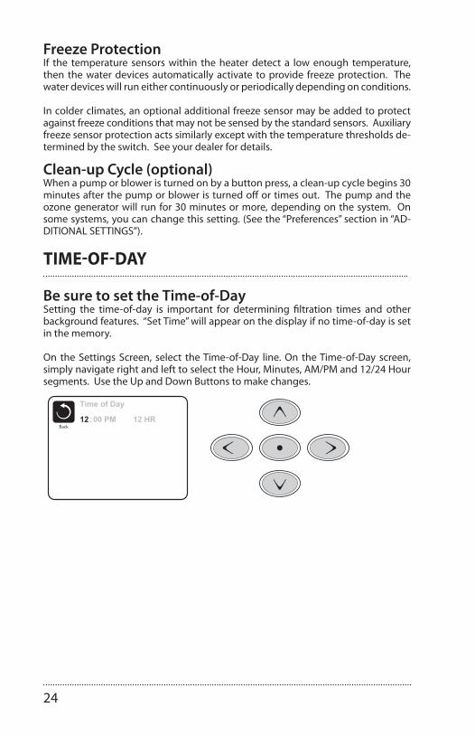
Be sure to set the Time-of-DaySetting the time-of-day is important for determining filtration times and other background features. “Set Time” will appear on the display if no time-of-day is set in the memory.
On the Settings Screen, select the Time-of-Day line. On the Time-of-Day screen, simply navigate right and left to select the Hour, Minutes, AM/PM and 12/24 Hour segments. Use the Up and Down Buttons to make changes.
40985_F 12-08-119
Manufactured under one or more of these patents. U.S. Patents: 5332944, 5361215, 5550753, 5559720, 5,883,459, 6253227, 6282370, 6590188, 6976052, 6965815, 7030343, 7,417,834 b2,Canadian Patent: 2342614, Australian patent: 2373248 other patents both foreign and domestic applied for and pending. All material copyright of Balboa Water Group.
Time-of-DayBe sure to set the Time-of-DaySetting the time-of-day is important for determining fi ltration times and other background features.
“Set Time” will appear on the display if no time-of-day is set in the memory.
On the Settings Screen, select the Time-of-Day line. On the Time-of-Day screen, simply navigate right and left to select the Hour, Minutes, AM/PM and 12/24 Hour segments. Use the Up and Down Buttons to make changes.
Saving SettingsThe Time-of-Day screen is a simple, editable screen that illustrates a feature of the control that applies to all other editable screens as well.
When changes are made, the icon to go “Back” changes to “Save” and a new icon for “Cancel” appears under the Save icon. Navigating to the left will highlight the Save icon, and navigating down from there will allow the user to cancel the pend-ing change. Pressing the “Select” button will save or cancel the changes and go back to the previous screen.
Note:If power is interrupted to the system, Time-of-Day will be maintained for several days.
Time of Day
Back12 :00 PM 12 HR
Time of Day
Back12 :00 PM 12 HR
Cancel
Save10:05 PM 12 HR

25
Saving SettingsThe Time-of-Day screen is a simple, editable screen that illustrates a feature of the control that applies to all other editable screens as well.
When changes are made, the icon to go “Back” changes to “Save” and a new icon for “Cancel” appears under the Save icon. Navigating to the left will highlight the Save icon, and navigating down from there will allow the user to cancel the pending change. Pressing the “Select” button will save or cancel the changes and go back to the previous screen.
40985_F 12-08-119
Manufactured under one or more of these patents. U.S. Patents: 5332944, 5361215, 5550753, 5559720, 5,883,459, 6253227, 6282370, 6590188, 6976052, 6965815, 7030343, 7,417,834 b2,Canadian Patent: 2342614, Australian patent: 2373248 other patents both foreign and domestic applied for and pending. All material copyright of Balboa Water Group.
Time-of-DayBe sure to set the Time-of-DaySetting the time-of-day is important for determining fi ltration times and other background features.
“Set Time” will appear on the display if no time-of-day is set in the memory.
On the Settings Screen, select the Time-of-Day line. On the Time-of-Day screen, simply navigate right and left to select the Hour, Minutes, AM/PM and 12/24 Hour segments. Use the Up and Down Buttons to make changes.
Saving SettingsThe Time-of-Day screen is a simple, editable screen that illustrates a feature of the control that applies to all other editable screens as well.
When changes are made, the icon to go “Back” changes to “Save” and a new icon for “Cancel” appears under the Save icon. Navigating to the left will highlight the Save icon, and navigating down from there will allow the user to cancel the pend-ing change. Pressing the “Select” button will save or cancel the changes and go back to the previous screen.
Note:If power is interrupted to the system, Time-of-Day will be maintained for several days.
Time of Day
Back12 :00 PM 12 HR
Time of Day
Back12 :00 PM 12 HR
Cancel
Save10:05 PM 12 HR
Note: If power is interrupted to the system, Time-of-Day will be maintained for several days.
ADJUSTING FILTRATION
Main FiltrationUsing the same navigation and adjustment as Setting the Time, Filter Cycles are set us-ing a start time and a duration. Each setting can be adjusted in 15-minute increments. The panel calculates the end time and displays it automatically.
40985_F 12-08-1110
Manufactured under one or more of these patents. U.S. Patents: 5332944, 5361215, 5550753, 5559720, 5,883,459, 6253227, 6282370, 6590188, 6976052, 6965815, 7030343, 7,417,834 b2,Canadian Patent: 2342614, Australian patent: 2373248 other patents both foreign and domestic applied for and pending. All material copyright of Balboa Water Group.
Adjusting FiltrationMain FiltrationUsing the same navigation and adjustment as Setting the Time, Filter Cycles are set using a start time and a duration. Each setting can be adjusted in 15-minute increments. The panel calculates the end time and displays it automatically.
Filter Cycle 2 - Optional FiltrationFilter Cycle 2 is OFF by default.
Simply navigate to the Filter Cycle 2 line by pressing the Right Navigation Button, and when “NO” is highlighted, press Up or Down to toggle Filter Cycle 2 on and off. When Filter Cycle 2 is ON, it can be adjusted in the same manner as Filter Cycle 1 by navigating to the right.
It is possible to overlap Filter Cycle 1 and Filter Cycle 2, which will shorten overall fi ltration by the overlap amount.
Circulation Pump ModesSome spas may be manufactured with Circ Pump settings that allow programming fi ltration cycle duration. Some circ Modes are pre-programmed to operate 24 hours a day and are not programmable. Refer to the spa manufacturer’s documentation for any Circ Mode details.
Purge CyclesIn order to maintain sanitary conditions, as well as protect against freezing, secondary water devices will purge water from their respective plumbing by running briefl y at the beginning of each fi lter cycle.
If the Filter Cycle 1 duration is set for 24 hours, enabling Filter Cycle 2 will initiate a purge when Filter Cycle 2 is pro-grammed to begin.
Filter Cycles
BackFilter Cycle 1 Starts at 12:00 AM Runs 0 HR 0 Min Ends at 12:00 AMFilter Cycle 2 NO Starts at 12:00 AM Runs 0 HR 0 Min Ends at 12:00 AM
Filter Cycles
BackFilter Cycle 1 Starts at 6:15 AM Runs 3 HR 0 Min Ends at 9:15 AMFilter Cycle 2 NO Starts at 12:00 AM Runs 0 HR 0 Min Ends at 12:00 AM
Cancel
Save
Filter Cycle 2 - Optional FiltrationFilter Cycle 2 is OFF by default. Simply navigate to the Filter Cycle 2 line by pressing the Right Navigation Button, and when “NO” is highlighted, press Up or Down to toggle Filter Cycle 2 on and off. When Filter Cycle 2 is ON, it can be adjusted in the same manner as Filter Cycle 1 by navigating to the right.
It is possible to overlap Filter Cycle 1 and Filter Cycle 2, which will shorten overall filtration by the overlap amount.
26
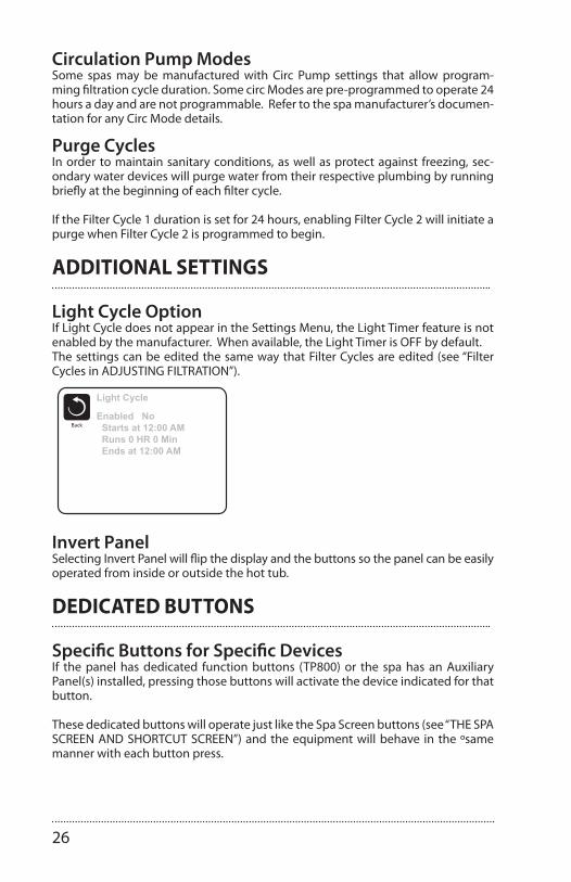
Circulation Pump ModesSome spas may be manufactured with Circ Pump settings that allow program-ming filtration cycle duration. Some circ Modes are pre-programmed to operate 24 hours a day and are not programmable. Refer to the spa manufacturer’s documen-tation for any Circ Mode details.
Purge CyclesIn order to maintain sanitary conditions, as well as protect against freezing, sec-ondary water devices will purge water from their respective plumbing by running briefly at the beginning of each filter cycle.
If the Filter Cycle 1 duration is set for 24 hours, enabling Filter Cycle 2 will initiate a purge when Filter Cycle 2 is programmed to begin.
ADDITIONAL SETTINGS
Light Cycle OptionIf Light Cycle does not appear in the Settings Menu, the Light Timer feature is not enabled by the manufacturer. When available, the Light Timer is OFF by default.The settings can be edited the same way that Filter Cycles are edited (see “Filter Cycles in ADJUSTING FILTRATION”).
40985_F 12-08-1111
Manufactured under one or more of these patents. U.S. Patents: 5332944, 5361215, 5550753, 5559720, 5,883,459, 6253227, 6282370, 6590188, 6976052, 6965815, 7030343, 7,417,834 b2,Canadian Patent: 2342614, Australian patent: 2373248 other patents both foreign and domestic applied for and pending. All material copyright of Balboa Water Group.
Light Cycle OptionIf Light Cycle does not appear in the Settings Menu, the Light Timer feature is not enabled by the manufacturer.
When available, the Light Timer is OFF by default.
The settings can be edited the same way that Filter Cycles are edited (see page 10).
Specifi c Buttons for Specifi c DevicesIf the panel has dedicated function buttons (TP800) or the spa has an Auxiliary Panel(s) installed, pressing those buttons will activate the device indicated for that button.
These dedicated buttons will operate just like the Spa Screen buttons (see page 4) and the equipment will behave in the same manner with each button press.
Additional Settings
Dedicated Buttons
Light Cycle
BackEnabled No Starts at 12:00 AM Runs 0 HR 0 Min Ends at 12:00 AM
Invert PanelSelecting Invert Panel will fl ip the display and the buttons so the panel can be easily operated from inside or outside the hot tub.
Invert PanelSelecting Invert Panel will flip the display and the buttons so the panel can be easily operated from inside or outside the hot tub.
DEDICATED BUTTONS
Specific Buttons for Specific DevicesIf the panel has dedicated function buttons (TP800) or the spa has an Auxiliary Panel(s) installed, pressing those buttons will activate the device indicated for that button.
These dedicated buttons will operate just like the Spa Screen buttons (see “THE SPA SCREEN AND SHORTCUT SCREEN”) and the equipment will behave in the ºsame manner with each button press.

27
RESTRICTING OPERATION
The control can be restricted to prevent unwanted use or temperature adjustments. Locking the Panel prevents the controller from being used, but all automatic func-tions are still active.
Locking the Settings allows Jets and other features to be used, but the Set Tempera-ture and other programmed settings cannot be adjusted.
Settings Lock allows access to a reduced selection of menu items. These include Set Temperature, Invert, Lock, Utilities, Information and Fault Log. They can be seen, but not changed or edited.
40985_F 12-08-1112
Manufactured under one or more of these patents. U.S. Patents: 5332944, 5361215, 5550753, 5559720, 5,883,459, 6253227, 6282370, 6590188, 6976052, 6965815, 7030343, 7,417,834 b2,Canadian Patent: 2342614, Australian patent: 2373248 other patents both foreign and domestic applied for and pending. All material copyright of Balboa Water Group.
Restricting Operation
Unlocking
An Unlock Sequence using the navigation buttons can be used from the Lock Screen. The Unlock Sequence is the same for both Panel Lock and Settings Lock.
The control can be restricted to prevent unwanted use or temperature adjustments.
Locking the Panel prevents the controller from being used, but all automatic functions are still active.
Locking the Settings allows Jets and other features to be used, but the Set Temperature and other programmed settings cannot be adjusted.
Settings Lock allows access to a reduced selection of menu items. These include Set Temperature, Invert, Lock, Utilities, Information and Fault Log. They can be seen, but not changed or edited.
Lock
BackSettingsPanel
OFFOFF
Lock
BackSettingsPanel
OFFONSet: 104°F
8:32 PMOzoneFilter 1
Unlock
High Range102°F
Ready in Rest ModeHeating
UNLOCKING
40985_F 12-08-1112
Manufactured under one or more of these patents. U.S. Patents: 5332944, 5361215, 5550753, 5559720, 5,883,459, 6253227, 6282370, 6590188, 6976052, 6965815, 7030343, 7,417,834 b2,Canadian Patent: 2342614, Australian patent: 2373248 other patents both foreign and domestic applied for and pending. All material copyright of Balboa Water Group.
Restricting Operation
Unlocking
An Unlock Sequence using the navigation buttons can be used from the Lock Screen. The Unlock Sequence is the same for both Panel Lock and Settings Lock.
The control can be restricted to prevent unwanted use or temperature adjustments.
Locking the Panel prevents the controller from being used, but all automatic functions are still active.
Locking the Settings allows Jets and other features to be used, but the Set Temperature and other programmed settings cannot be adjusted.
Settings Lock allows access to a reduced selection of menu items. These include Set Temperature, Invert, Lock, Utilities, Information and Fault Log. They can be seen, but not changed or edited.
Lock
BackSettingsPanel
OFFOFF
Lock
BackSettingsPanel
OFFONSet: 104°F
8:32 PMOzoneFilter 1
Unlock
High Range102°F
Ready in Rest ModeHeating
An Unlock Sequence using the navigation buttons can be used from the Lock Screen. The Unlock Sequence is the same for both Panel Lock and Settings Lock.
40985_F 12-08-1112
Manufactured under one or more of these patents. U.S. Patents: 5332944, 5361215, 5550753, 5559720, 5,883,459, 6253227, 6282370, 6590188, 6976052, 6965815, 7030343, 7,417,834 b2,Canadian Patent: 2342614, Australian patent: 2373248 other patents both foreign and domestic applied for and pending. All material copyright of Balboa Water Group.
Restricting Operation
Unlocking
An Unlock Sequence using the navigation buttons can be used from the Lock Screen. The Unlock Sequence is the same for both Panel Lock and Settings Lock.
The control can be restricted to prevent unwanted use or temperature adjustments.
Locking the Panel prevents the controller from being used, but all automatic functions are still active.
Locking the Settings allows Jets and other features to be used, but the Set Temperature and other programmed settings cannot be adjusted.
Settings Lock allows access to a reduced selection of menu items. These include Set Temperature, Invert, Lock, Utilities, Information and Fault Log. They can be seen, but not changed or edited.
Lock
BackSettingsPanel
OFFOFF
Lock
BackSettingsPanel
OFFONSet: 104°F
8:32 PMOzoneFilter 1
Unlock
High Range102°F
Ready in Rest ModeHeating
28
RESTRICTING OPERATION
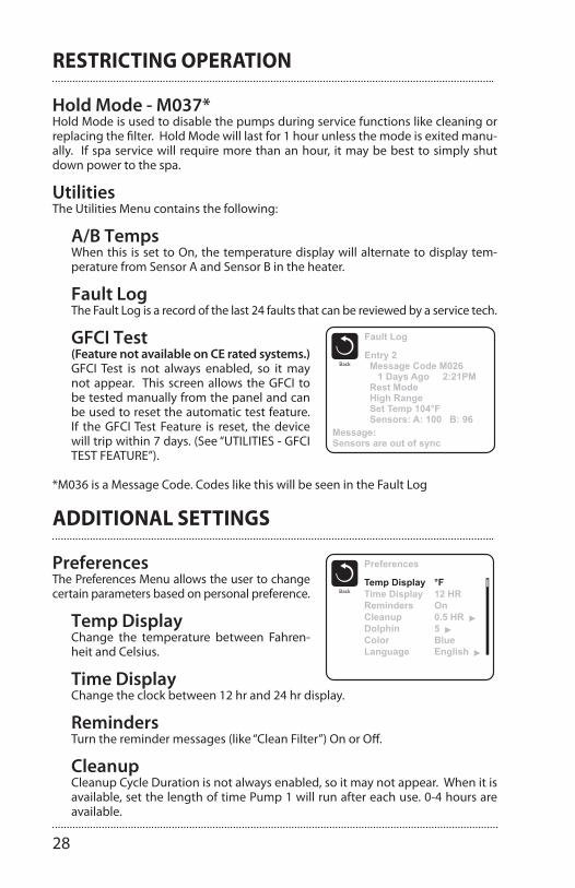
Hold Mode - M037*Hold Mode is used to disable the pumps during service functions like cleaning or replacing the filter. Hold Mode will last for 1 hour unless the mode is exited manu-ally. If spa service will require more than an hour, it may be best to simply shut down power to the spa.
UtilitiesThe Utilities Menu contains the following:
A/B TempsWhen this is set to On, the temperature display will alternate to display tem-perature from Sensor A and Sensor B in the heater.
Fault LogThe Fault Log is a record of the last 24 faults that can be reviewed by a service tech.
40985_F 12-08-1113
Manufactured under one or more of these patents. U.S. Patents: 5332944, 5361215, 5550753, 5559720, 5,883,459, 6253227, 6282370, 6590188, 6976052, 6965815, 7030343, 7,417,834 b2,Canadian Patent: 2342614, Australian patent: 2373248 other patents both foreign and domestic applied for and pending. All material copyright of Balboa Water Group.
Additional SettingsHold Mode - M037*Hold Mode is used to disable the pumps during service functions like cleaning or replacing the fi lter. Hold Mode will last for 1 hour unless the mode is exited manually. If spa service will require more than an hour, it may be best to simply shut down power to the spa.
Drain ModeSome spas have a special feature that allows Pump 1 to be employed when draining the water. When available, this feature is a component of Hold Mode.
Utilities The Utilities Menu contains the following:
A/B Temps When this is set to On, the temperature display will alternate to display temperature from Sensor A and Sensor B in the heater.
Demo Mode Demo Mode is not always enabled, so it may not appear. This is designed to operate several devices in a sequence in order to demonstrate the various features of a particular hot tub.
Fault Log The Fault Log is a record of the last 24 faults that can be reviewed by a service tech.
GFCI Test (Feature not available on CE rated systems.) GFCI Test is not always enabled, so it may not appear. This screen allows the GFCI to be tested manually from the panel and can be used to reset the automatic test feature. If the GFCI Test Feature is reset, the device will trip within 7 days. (See Page 16)
Fault Log
BackEntry 2 Message Code M026 1 Days Ago 2:21PM Rest Mode High Range Set Temp 104°F Sensors: A: 100 B: 96
Message:Sensors are out of sync
*M036 is a Message Code. Codes like this will be seen in the Fault Log
GFCI Test(Feature not available on CE rated systems.)GFCI Test is not always enabled, so it may not appear. This screen allows the GFCI to be tested manually from the panel and can be used to reset the automatic test feature. If the GFCI Test Feature is reset, the device will trip within 7 days. (See “UTILITIES - GFCI TEST FEATURE”).
*M036 is a Message Code. Codes like this will be seen in the Fault Log
ADDITIONAL SETTINGS
40985_F 12-08-1114
Manufactured under one or more of these patents. U.S. Patents: 5332944, 5361215, 5550753, 5559720, 5,883,459, 6253227, 6282370, 6590188, 6976052, 6965815, 7030343, 7,417,834 b2,Canadian Patent: 2342614, Australian patent: 2373248 other patents both foreign and domestic applied for and pending. All material copyright of Balboa Water Group.
Additional SettingsPreferences The Preferences Menu allows the user to change certain parameters based on personal preference.
Temp Display Change the temperature between Fahrenheit and Celsius.
Time Display Change the clock between 12 hr and 24 hr display.
Reminders Turn the reminder messages (like “Clean Filter”) On or Off.
Cleanup Cleanup Cycle Duration is not always enabled, so it may not appear. When it is available, set the length of time Pump 1 will run after each use. 0-4 hours are available.
Dolphin II and Dolphin III (Applies to RF Dolphin only) When set to 0, no addressing is used. Use this setting for a Dolphin II or Dolphin III which is factory set for no address by default. When set between 1 and 7, the number is the address. (See the Dolphin manual for details.)
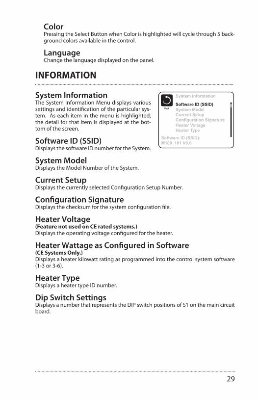
Color Pressing the Select Button when Color is highlighted will cycle through 5 background colors available in the control.
Language Change the language displayed on the panel.
Preferences
BackTemp DisplayTime DisplayRemindersCleanupDolphinColorLanguage
°F12 HROn0.5 HR5BlueEnglish
PreferencesThe Preferences Menu allows the user to change certain parameters based on personal preference.
Temp DisplayChange the temperature between Fahren-heit and Celsius.
Time DisplayChange the clock between 12 hr and 24 hr display.
RemindersTurn the reminder messages (like “Clean Filter”) On or Off.
CleanupCleanup Cycle Duration is not always enabled, so it may not appear. When it is available, set the length of time Pump 1 will run after each use. 0-4 hours are available.
29
ColorPressing the Select Button when Color is highlighted will cycle through 5 back-ground colors available in the control.
LanguageChange the language displayed on the panel.
INFORMATION
40985_F 12-08-1115
Manufactured under one or more of these patents. U.S. Patents: 5332944, 5361215, 5550753, 5559720, 5,883,459, 6253227, 6282370, 6590188, 6976052, 6965815, 7030343, 7,417,834 b2,Canadian Patent: 2342614, Australian patent: 2373248 other patents both foreign and domestic applied for and pending. All material copyright of Balboa Water Group.
Information System Information The System Information Menu displays various settings and identifi cation of the particular system. As each item in the menu is highlighted, the detail for that item is displayed at the bottom of the screen.
Software ID (SSID) Displays the software ID number for the System.
System Model Displays the Model Number of the System.
Current Setup Displays the currently selected Confi guration Setup Number.
Confi guration Signature Displays the checksum for the system confi guration fi le.
Heater Voltage (Feature not used on CE rated systems.) Displays the operating voltage confi gured for the heater.
Heater Wattage as Confi gured in Software (CE Systems Only.)Displays a heater kilowatt rating as programmed into the control system software (1-3 or 3-6).
Heater Type Displays a heater type ID number.
Dip Switch Settings Displays a number that represents the DIP switch positions of S1 on the main circuit board.
Panel Version Displays a number of the software in the topside control panel.
System Information
BackSoftware ID (SSID)System ModelCurrent SetupConfiguration SignatureHeater VoltageHeater Type
Software ID (SSID):M100_101 V0.6
System InformationThe System Information Menu displays various settings and identification of the particular sys-tem. As each item in the menu is highlighted, the detail for that item is displayed at the bot-tom of the screen.
Software ID (SSID)Displays the software ID number for the System.
System ModelDisplays the Model Number of the System.
Current SetupDisplays the currently selected Configuration Setup Number.
Configuration SignatureDisplays the checksum for the system configuration file.
Heater Voltage (Feature not used on CE rated systems.)Displays the operating voltage configured for the heater.
Heater Wattage as Configured in Software (CE Systems Only.)Displays a heater kilowatt rating as programmed into the control system software (1-3 or 3-6).
Heater TypeDisplays a heater type ID number.
Dip Switch SettingsDisplays a number that represents the DIP switch positions of S1 on the main circuit board.

30
UTILITIES – GFCI TEST FEATURE
40985_F 12-08-1116
Manufactured under one or more of these patents. U.S. Patents: 5332944, 5361215, 5550753, 5559720, 5,883,459, 6253227, 6282370, 6590188, 6976052, 6965815, 7030343, 7,417,834 b2,Canadian Patent: 2342614, Australian patent: 2373248 other patents both foreign and domestic applied for and pending. All material copyright of Balboa Water Group.
The Ground Fault Circuit Interrupter (GFCI) or Residual Current Detector (RCD) is an important safety device and is required equipment on a hot tub installation.
(The GFCI Test Feature is not available on CE rated systems.)
Used for verifying a proper installationYour spa may be equipped with a GFCI Protection feature. If your spa has this feature enabled by the manufacturer, the GFCI Trip Test must occur to allow proper spa function.
Within 1 to 7 days after startup, the spa will trip the GFCI to test it. (The number of days is factory programmed.) The GFCI must be reset once it has tripped. After passing the GFCI Trip Test, any subsequent GFCI trips will indicate a ground fault or other unsafe condition and the power to the spa must be shut off until a service person can correct the problem.
Forcing the GFCI Trip Test (North America Only)The installer can cause the GFCI Trip Test to occur sooner by initiating it using the above menu.
The GFCI should trip within several seconds and the spa should shut down. If it does not, shut down the power and manually verify that a GFCI breaker is installed and that the circuit and spa are wired correctly. Verify the function of the GFCI with its own test button. Restore power to the spa and repeat the GFCI Trip Test.
Once the GFCI is tripped by the test, reset the GFCI and the spa will operate normally from that point. You can verify a successful test by navigating to the above menu. PASS should appear after a temp button is pressed from the GFCI screen.
Warning:The end-user must be trained to expect this one-time test to occur and how to properly reset the GFCI.
If freezing conditions exist, the GFCI or RCD should be reset immediately or spa damage could result.
CE Product:CE registered systems do not have an RCD Test Feature due to the nature of the electrical service.
Some UL registered systems do not have the GFCI Test Feature activated.
The end-user must be trained how to properly test and reset the RCD.
Utilities – GFCI Test FeatureGFCI Status - Passed
BackTestResetThe Ground Fault Circuit Interrupter (GFCI) or
Residual Current Detector (RCD) is an important safety device and is required equipment on a hot tub installation.
(The GFCI Test Feature is not available on CE rated systems.)
Used for verifying a proper installationYour spa may be equipped with a GFCI Protection feature. If your spa has this feature enabled by the manufacturer, the GFCI Trip Test must occur to allow proper spa function.
Within 1 to 7 days after startup, the spa will trip the GFCI to test it. (The number of days is factory programmed.) The GFCI must be reset once it has tripped. After passing the GFCI Trip Test, any subsequent GFCI trips will indicate a ground fault or other unsafe condition and the power to the spa must be shut off until a service person can correct the problem.
Forcing the GFCI Trip Test (North America Only) The installer can cause the GFCI Trip Test to occur sooner by initiating it using the above menu. The GFCI should trip within several seconds and the spa should shut down. If it does not, shut down the power and manually verify that a GFCI breaker is installed and that the circuit and spa are wired correctly. Verify the function of the GFCI with its own test button. Restore power to the spa and repeat the GFCI Trip Test.
Once the GFCI is tripped by the test, reset the GFCI and the spa will operate normally from that point. You can verify a successful test by navigating to the above menu. PASS should appear after a temp button is pressed from the GFCI screen.
Warning:The end-user must be trained to expect this one-time test to occur and how to properly reset the GFCI. If freezing conditions exist, the GFCI or RCD should be reset immediately or spa damage could result.
CE Product:CE registered systems do not have an RCD Test Feature due to the nature of the electrical service. Some UL registered systems do not have the GFCI Test Feature activated. The end-user must be trained how to properly test and reset the RCD.
31
WATER PURITY & FILTRATION
Keeping the water clean – chemical sanitizersOne of the bigger reasons that people require service on their spa is because they haven’t followed a chemical application regiment. Water can accumulate impuri-ties that can worsen the performance or even damage the filtration system if chemicals are not applied on a regular basis. The water can even become unhealthy if chemicals are not used to sanitize the water. Improper pH levels or calcium levels can cause either corrosion of parts or scale build-up.
We recommend that you begin a routine of applying chemicals that you can get comfortable with and follow all the time. If you get into a scheduled regiment, it will be easier to remember when to apply the chemicals.
Your spa comes with an ozonator that will do a very good job at kill-ing bacteria and oxygenating the water, but chlorine or bromine are used to compliment the job of the ozonator.
Finally, the best way to keep the water clean over long periods of time is to change the water four times a year. Connect a hose to the drain valve and open it all the way to allow the tub to drain all the way. Use a shop-vac to remove any standing water and debris at the bottom of the tub. Refer to the maintenance section for instructions on cleaning the tub before refilling it.
Spa Chemistry 101At first, trying to understand spa chemistry can seem like a daunt-ing task to say the least. We intend on helping you understand spa chemicals so that you can maintain the health of your spa at the best level possible.
There are three basic principals to spa water chemistry.
1. Sanitize/Disinfect (kill viruses, germs, etc.) 2. Oxidize (break down organic compounds like oils and sweat) 3. Maintain slightly base (alkaline) water (pH of 7.4 - 7.6). This controls the corrosiveness of the water, prevents excessive scaling (mineral formation on surfaces exposed to water, and insures that the water is comfortable to the skin.
Once you have a good understanding of the chemicals that are used in your spa, you will be able to maintain proper water balance. Water balance is reached when all elements (pH, total alkalinity, calcium hardness and total dissolved solids) are within their proper ranges.
IMPORTANT!Always read
directions onchemical container
thoroughlybefore
using spa chemicals.
The pH scale goes from
0 to 14, with zero beingextremely
acidic and 14 being extremely base (alkaline).
Seven isconsidered neutral pH.

32
The following definitions for chemicals will help you understand what the chemical is and what it is used for:
Sanitizers
CHLORINE - Chlorine is widely used as a sanitizer or disinfectant in pool and spa water to kill bacteria, viruses and algae, and oxidizes ammonia and nitrogen com-pounds such as swimmer waste. Its formal name is Sodium Dichlor and is referred to as a chlorinated concentrate. Sodium Dichlor is a fast-dissolving, granular, stabi-lized organic chlorine compound providing either 56% or 63% available chlorine. Cyanuric acid and/or stabilizers are added to prevent U.V. light destruction of the chlo-rine by the sun.
Chlorinated concentrate produces chlorides and chloramines, which are formed when chlorine has combined with ammonia and nitrogen in pool and spa water. Chloramines exude a foul, “chlorine” odor and causes skin and eye irritation.
BROMINE – Bromine is the other commonly used sanitizer or disinfectant in pool and spa water to kill bacteria and algae, and oxidizes ammonia and nitrogen com-pounds such as swimmer waste. This chemical does not eliminate swimmer waste unless it is combined with an oxidizer (non-chlorine shock). It is very susceptible to direct sunlight, therefore is not efficient in outdoor pools. Bromine is sometimes used as an alternative for people whom are allergic or sensitive to chlorine products.
Bromine products are available as sodium bromide and bromine tablets. The bro-mide ion has no effective disinfectant or sanitizing capabilities without the use of nonchlorine shock (potassium monopersulfate). Potassium monopersulfate is added to oxidize, or activate, bromide ion to bromine, which rapidly forms the ac-tive sanitizer - hypobromous acid - in spa water. Upon reaction with bacteria and other spa contaminants, hypobromous acid is reduced back to bromide ion, ready to be activated again by the next dose of potassium monopersulfate. Potassium monopersulfate begins to produce bromine immediately and continues to do so for several hours, providing sufficient time for oxidation of bather waste and other organic contamination such as ammonia and nitrogen.
NON-CHLORINE SHOCK (Potassium Monopersulfate) – Also knownas “Oxy-Shock”, is an important chemical used in the process of disinfecting and sanitizing the spa water. Non-chlorine shock is used as an oxidation agent to oxi-dize and eliminate organic contaminants, dead algae and debris, and will also con-vert the chlorine by-products (chlorides and chloramines) back into free available chlorine.
When used with bromine products, non-chlorine shock is used with sodium bro-mide in a two-part disinfection system. Potassium monopersulfate (non- chlorine shock) is added to oxidize, or activate, bromide ion to bromine which rapidly forms the active sanitizer - hypobromous acid - in spa water. Upon reaction with bacteria and other spa contaminants, hypobromous acid is reduced back to bromide ion, ready to be activated again by the next dose of potassium monopersulfate.Most non-chlorine shock products have buffers that reduce pH instability, and cor-rosion inhibitors that help protect the heater and other metal surfaces.
OZONE – Ozone is a powerful gas that is used as a sanitizer and an oxidant to keep

33
the spa water clean and disinfected. Although ozone is about 3000 times more powerful than chlorine, it has a tendency to dissipate quickly and does not create any sanitizer residual. By using an ozonator for your spa, you can cut maintenance time and chemical costs by as much as 60%. Ozone is manufactured by an ozona-tor (ozone generator) and is dispensed during the filtration mode.
pH Controllers
SODIUM BICARBONATE - Commonly used to increase pH and total alkalinity of spa water. Sodium bicarbonate is also known as natural baking soda.
SODIUM CARBONATE – Also known as soda ash, is a substance used to raise pH and total alkalinity.
SODIUM BISULFATE – Also known as dry acid, the chemical used to lower pH and total alkalinity of spa water.
MURIATIC ACID – A liquid acid that is most commonly used to reduce pH and total alkalinity levels. It tends to be very strong and is not recommended for use in spas.
Water Conditioners
FLOCCULENT – A compound which clarifies spa water by gathering oils, dirt, scum, metal deposits and small contaminant particles into larger globules, which then can be easily trapped in the filtering system allowing the filtering system to work more effectively.
CLARIFIER – A compound used to remove dissolved solids, metals, dirt, oils, or other contaminants from spa and pool water.
SCUM BALL™ – A softball sized ball that is kept in the water. The ball is chemically treated so that it attracts contaminants that would normally be trapped in the filter.
SEQUESTERING AGENT – Stain & scale preventing compounds that sequester dis-solved metals to prevent water discoloration.
CALCIUM CHLORIDE – A soluble white compound used to raise the calcium hard-ness of spa & pool water, to protect equipment from corrosion.
ALGAECIDE – A chemical used to kill algae and prevent it from growing back.
DEFOAMER – A compound used to reduce or eliminate foaming in spa water. Products containing Chitin do this naturally.
CHITIN – A naturally occurring polymer (pronounced KY-tin) found in crab and lobster shells. As a spa clarifier, it is the best flocculating agent available. Removes oils, dirt, scum, and metal deposits and allows the filtering system to work more effectively.
How To Use The ChemicalsNow that you have some knowledge about spa chemicals, you will learn how to use those chemicals to maintain balanced water in your spa. This section will ex-plain how to apply chemicals, how much to use, and when to use them.

34
Usage DefinitionsBefore getting into how much and when, it is important to understand some of the terminology that is used to describe how the chemicals are applied:
P.P.M. – Parts Per Million. Expressed as a ratio of number out of 1 million.
SHOCK – Addition of an oxidizer (OXY SHOCK) or superchlorinator to the water to break-down the organic contaminates on which bacteria feed and to destroy am-monia and nitrogen compounds (oxidize only).
SUPERCHLORINATION – Means the addition of enough chlorine in the water to kill all living things (sanitize) and destroy any organic wastes present in the water (oxi-dize). Usually this means about double your normal dose of chlorine. Superchlorina-tion can be done once a day for heavy bather loads or as infrequent as once a week for a moderately used spa.
CHLORINATION – To add chlorine to your spa on a regular basis to disinfect and oxidize your spa water.
BREAK POINT CHLORINATION – The process of shocking the water with significant quantities of chlorine to oxidize all contaminants and organic wastes and leave all remaining chlorine as free chlorine.
CALCIUM HARDNESS – A measure of the amount of calcium dissolved in water. Wa-ter with low hardness can lead to corrosion of metal parts. Water with high level of hardness can cause scale (calcium crust) build up on spa surfaces and clog filters, heaters and pumps.
WATER BALANCE – Water balance is reached when all elements (pH, total alkalinity, calcium hardness and total dissolved solids) are within their proper ranges.
ENZYMES – Biodegradable proteins which breakdown oils, films and digest scum in spa water.
FREE CHLORINE – The amount of chlorine available to kill bacteria or algae. Also known as “Available Chlorine”.
COMBINED CHLORINE – The portion of the total chlorine in water in chemical com-bination with ammonia, organics, and nitrogen, most of which are chloramines.
TOTAL ALKALINITY (TA) – The measure in PPM of all the dissolvedbase/alkaline material in the water. The acid-neutralizing capacity of water which in-dicates its buffering ability, or resistance to fluctuations in pH.
TOTAL DISSOLVED SOLIDS (TDS) – The total amount of dissolved materials in pool or spa water. The ideal range is from 1,000 to 2,000 ppm in pools and 1,500 ppm above the start-up TDS in spas.
Starting A Chemical Maintenance ProgramUltimately, in a chemical maintenance program, the goal is to maintain water balance. If you apply chemicals and test your water on a regular basis, water balance is easy to maintain and your spa water will stay clear and healthy. Although test strips are fairly
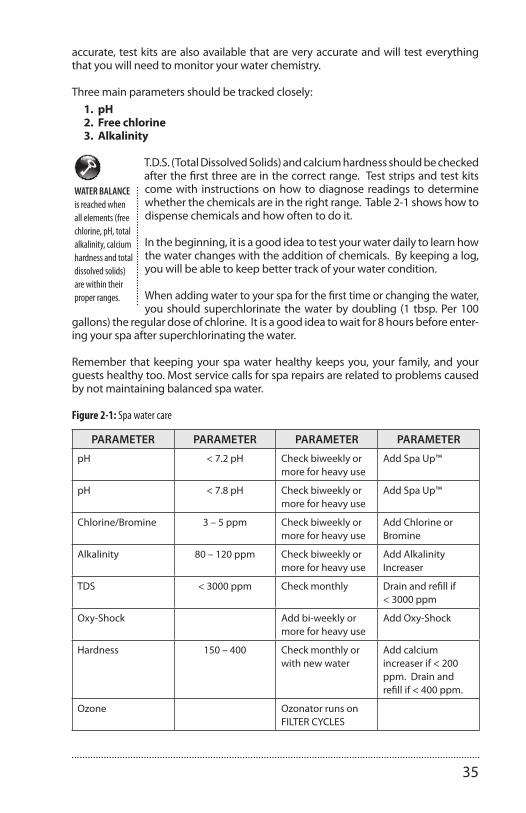
35
accurate, test kits are also available that are very accurate and will test everything that you will need to monitor your water chemistry.
Three main parameters should be tracked closely: 1. pH 2. Free chlorine 3. Alkalinity
T.D.S. (Total Dissolved Solids) and calcium hardness should be checked after the first three are in the correct range. Test strips and test kits come with instructions on how to diagnose readings to determine whether the chemicals are in the right range. Table 2-1 shows how to dispense chemicals and how often to do it.
In the beginning, it is a good idea to test your water daily to learn how the water changes with the addition of chemicals. By keeping a log, you will be able to keep better track of your water condition.
When adding water to your spa for the first time or changing the water, you should superchlorinate the water by doubling (1 tbsp. Per 100
gallons) the regular dose of chlorine. It is a good idea to wait for 8 hours before enter-ing your spa after superchlorinating the water.
Remember that keeping your spa water healthy keeps you, your family, and your guests healthy too. Most service calls for spa repairs are related to problems caused by not maintaining balanced spa water.
Figure 2-1: Spa water care
PARAMETER PARAMETER PARAMETER PARAMETER
pH < 7.2 pH Check biweekly or more for heavy use
Add Spa Up™
pH < 7.8 pH Check biweekly or more for heavy use
Add Spa Up™
Chlorine/Bromine 3 – 5 ppm Check biweekly or more for heavy use
Add Chlorine or Bromine
Alkalinity 80 – 120 ppm Check biweekly or more for heavy use
Add Alkalinity Increaser
TDS < 3000 ppm Check monthly Drain and refill if < 3000 ppm
Oxy-Shock Add bi-weekly or more for heavy use
Add Oxy-Shock
Hardness 150 – 400 Check monthly or with new water
Add calcium increaser if < 200 ppm. Drain and refill if < 400 ppm.
Ozone Ozonator runs on FILTER CYCLES
WATER BALANCE is reached when all elements (free chlorine, pH, totalalkalinity, calcium hardness and totaldissolved solids) are within theirproper ranges.

36
FiltrationYour spa is pre-programmed to run a 2-hour filter cycle twice a day.For the system to work properly, the filters must be hosed off at least once a week and thoroughly cleaned once a month with a filter de-greaser. We recommend that you buy an extra filter cartridge from your Clearwater Spas dealer to alternate with the filters included with your spa. A dirty filter will restrict water flow and will prohibit the filtering system from keeping your spa clean. If the filters are not cleaned for extended periods, it could possibly damage the pumps.
If you have a problem with floating contaminants, you may want to purchase a skimmer net to easily remove bugs, leaves, etc…
Details on cleaning the filters are included in the maintenance section, but as a reminder, it is important to first turn off the power to the spa. Leaving the power on while changing the filters could allow ob-jects to be drawn into the heater and/or pump and may damage your equipment.
FILTER REMOVAL OPTIONS:
A) To remove filters, DOUBLE CARTRIDGE - with turbine vane filter cover: (filter component colors and styles may vary)
Remove lid from the turbine vane filter cover.
Locate filter basket clips. Remove filter basket clips. Remove filter basket.
Locate top of filter. Insert two or three fingers into filter and pull out.
Clean or replace filter.
B) To remove filter, SINGLE CARTRIDGE - with telescoping weir: (filter component colors and styles may vary)
Turn filter housing ring counter-clockwise to remove housing and telescoping weir.
Lift and remove filter basket.
Insert two or three fingers into filter and pull out.
Clean or replace filter.
CAUTION!Turn off the power to the spa before removing the filter!
For the bestperformancepossible, clean the filter weekly.
37
C) To remove filter, DOUBLE CARTRIDGE - for spas that have one with a turbine vane filter cover and one with a telescoping weir:
Simply follow the steps in both filter removal options A & B.
Ask your Clearwater Spas dealer for more information on the new Microban Filters, a new technology with antimicrobial protection that will inhibit the growth of bacteria and mold.
Ozone GeneratorThe spa manufacturing company offers an optional Ozonator made to our specifi-cations. Ozonators supply the spa water with ozone, which is an extremely effec-tive oxidant that will kill bacteria and microorganisms. The Ozonator will distribute ozone into your spa automatically during the filter cycles and will keep your spa and water sparkling clean. Even though ozone is effective at keeping your water clean, it cannot replace the use of chlorine or bromine. Refer to the chemical sec-tion for more information.
No maintenance is necessary on the ozonator. The ozonator works during the filter cycles set by the controller only. If your spa did not include an optional ozonator and you would like to have one installed, contact your spa dealer.

38
Salt System with ISIS control panel.
NOTE: Anytime you add a chemical, turn the jets on to help dissolve it appropriately.
The control of the ISIS Top Side is identical to the ISIS 1 controller. The user interface is as follows:• To activate the topside control, any of the push button keys must be held down for the entire Key Lockout deactivation sequence which takes several seconds.• If the Key Lockout has been activated and any push button key is pressed, the three digit Seven Segment Display will display “Loc”.• After one second, the three digit Seven Segment Display will display a “3” in the center digit.• The push button key must be held down until the three digit Seven Segment
Display decreases to “1” and the power setting is displayed, then bromine out-put or boost can be adjusted.
• The displayed count will be displayed as quickly as in 0.75 second intervals. If the depressed push button key is not released within five seconds after the power setting is displayed, the Key Lockout will be reactivated preventing an accidental increase or decrease in bromine production ( this is a precautionary – safety feature of the ISIS TS System).
• After the power setting is displayed, the push button keys are activated and power setting is enabled (normal error code display is also resumed). If any key remains depressed for five seconds during the deactivated Key Lockout period, the Key Lockout will reactivate and disable control features.
• The Key Lockout will reactivate in 20 seconds after the last operational release of a push button key. The three digit Seven Segment Display will display “Loc” for 0.5 seconds when Key Lockout is reactivated.
• Upon reactivation of the Key Lockout, the Topside Control Seven Segment Display will display the power setting along with any active error codes or power setting LED displays. If the Electrode Current display feature is enabled, the Key Lockout will not reactivate.
It may take a few hours up to a day to reach the desired level of Bromine (sanitizer). The correct level of Bromine with the Genesis System should be between 0-1 on the generic bromine test strip. The strips that test for the active bromine (sanitizer) level are designed for generic bromine systems. Specifically for Genesis, if the bro-mine level reads 2 or more (which reads ok on the test strip) then there is actually too much pure bromine in your spa. For the Genesis system that produces a more “pure” sanitizer (without any “fillers” or extra chemicals), the “OK” range for the bro-mine will read between 0-1 (light green) on a common bromine test strip.
Between 0-1 on the test strip is where you want your Bromine (sanitizer) level to remain. For continued water care, adjust the Genesis control dial as needed to remain in the “true” ok range (0-1) and “balance” your water regularly. Continue to test the water at least once weekly to monitor the water quality. If you do not use
LEGENDFORISISCONTROLLER “tdS”totaldissolvedsolids toohigh. “OE”openelement-detects aninadequateconnection.
“SE”shortenedelement detectsexcessivecurrent.
“bSt”boostkeyallowsyouto boostthebromine.
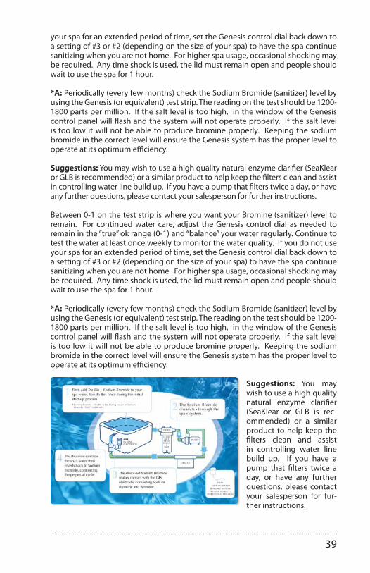
39
your spa for an extended period of time, set the Genesis control dial back down to a setting of #3 or #2 (depending on the size of your spa) to have the spa continue sanitizing when you are not home. For higher spa usage, occasional shocking may be required. Any time shock is used, the lid must remain open and people should wait to use the spa for 1 hour.
*A: Periodically (every few months) check the Sodium Bromide (sanitizer) level by using the Genesis (or equivalent) test strip. The reading on the test should be 1200-1800 parts per million. If the salt level is too high, in the window of the Genesis control panel will flash and the system will not operate properly. If the salt level is too low it will not be able to produce bromine properly. Keeping the sodium bromide in the correct level will ensure the Genesis system has the proper level to operate at its optimum efficiency.
Suggestions: You may wish to use a high quality natural enzyme clarifier (SeaKlear or GLB is recommended) or a similar product to help keep the filters clean and assist in controlling water line build up. If you have a pump that filters twice a day, or have any further questions, please contact your salesperson for further instructions.
Between 0-1 on the test strip is where you want your Bromine (sanitizer) level to remain. For continued water care, adjust the Genesis control dial as needed to remain in the “true” ok range (0-1) and “balance” your water regularly. Continue to test the water at least once weekly to monitor the water quality. If you do not use your spa for an extended period of time, set the Genesis control dial back down to a setting of #3 or #2 (depending on the size of your spa) to have the spa continue sanitizing when you are not home. For higher spa usage, occasional shocking may be required. Any time shock is used, the lid must remain open and people should wait to use the spa for 1 hour.
*A: Periodically (every few months) check the Sodium Bromide (sanitizer) level by using the Genesis (or equivalent) test strip. The reading on the test should be 1200-1800 parts per million. If the salt level is too high, in the window of the Genesis control panel will flash and the system will not operate properly. If the salt level is too low it will not be able to produce bromine properly. Keeping the sodium bromide in the correct level will ensure the Genesis system has the proper level to operate at its optimum efficiency.
Suggestions: You may wish to use a high quality natural enzyme clarifier (SeaKlear or GLB is rec-ommended) or a similar product to help keep the filters clean and assist in controlling water line build up. If you have a pump that filters twice a day, or have any further questions, please contact your salesperson for fur-ther instructions.

40
Salt System with in.clear / Gecko control panel.
in.clear user manual
11
Maintenance Mode:
Maintenance Mode keeps the bromine bank levels at a stable and acceptable range when the spa is not being used� Maintenance Mode is the “everyday” mode and is automatically ON when the system is activated� Maintenance level adjustment changes the rate at which bromine will be released into the spa water�
Finding and setting the right maintenance level will keep the residual bromine level between 3 and 5 PPM (the recommended range) when the spa is not being used or is left unused for an extended period of time� Once the proper maintenance level is determined, keep the same setting unless the spa conditions change (change in water temperature, spa location etc)�
Finding the right bromine generation level is a crucial step for the in�clear system to be stable and effective�
The spa filtration should be set at a minimum of 8hrs per day�
It is important to note that the in�clear system can ONLY generate bromine when the water is circulating� If you are having problems maintaining a stable level of bromine, or determining the proper maintenance level for your spa, you may have to increase the daily filtering time� Longer filtration produces a more steady level of bromine�
Keypad functions
On/Off & Boost key
MaintenanceDiagnostic
key
Down keyUp key
Bromine generatorON indicator
lo hi
BromiCharge gauge
in.clear operating modes
Boost Mode:
The Boost Mode should be activated every time you use your spa� Boost Mode increases the bromine generation rate to attack pollutants in the water and helps rebuild the necessary residual bromine in the water after each use of the spa� Pollutants are introduced to the water by the bathers, causing the bromine levels to decrease� Activating the Boost Mode when you enter the spa will prevent inadequate bromine levels and will restore your bromine to the proper residual level�
Finding the right Boost level is another crucial step for the in�clear system to be stable and effective�
If water quality is not good after use, only the Boost level should be adjusted, not the Maintenance level�
Set the maintenance level
Determining the proper mainte-nance level for your spa is an ex-tremely important step. Using your spa while you’re establishing the residual will slow the process. Be patient. Make sure you follow steps 1 through 4 previously described be-fore performing the following steps.
1. Power up your spa and activate the system by pressing the Boost key .
2. Press and hold the Prog key for 2 seconds to enter maintenance lev-el adjustment mode. Your mainte-nance value was set at the factory and should read 15 to start. Leave the in.clear system running for 24 hours to allow the bromine level to stabilize. After that period, use test strips to check the bromine level.
3. Bromine level should be between 3-5 PPM. If the bromine level is within that range, you are ready to use your spa. If the bromine level is above 5 PPM, decrease the maintenance level. If the bromine level is below 3 PPM, increase the maintenance level. Use the Up and Down keys to adjust maintenance level. The bromine gen-eration rate ranges from 1 to 50, where 1 corresponds to the system’s minimum generating rate and 50 corresponds to the maximum generation rate allowed by the system.
Do NOT increase/decrease maintenance level in steps greater than 2.
Setting the maintenance level to a value that’s too high can cause damage to your equipment.
Check bromine level and always test water before entering the spa.
If the bromine level is higher than 5 PPM, lower the maintenance level and turn off the system until the bromine level is back below 5 PPM. Then, restart the system and continue monitoring the bromine level.
To lower the bromine level, expose your spa water to the sun and activate all pumps for a few cycles.
Testing bromine levels with FAS-DPD drop count method is more accurate than using test strips. Bromine FAS-DPD is available at www.geckodepot.com under number 0699-300008.

41
Determine the boost level
Every time you use your spa, activate the Boost Mode. As a rule of thumb, the Boost level corresponds to the number of bathers using the spa. For example, acti-vate the Boost level to 2 indicators if two bathers are entering the spa.
1. With the system in Maintenance Mode, press the Boost key to activate the Boost Mode.
2. The keypad display will show a numeric value that corresponds to the selected level. There are 8 possible levels available with the Boost Mode. Set the Boost level by using the up and down arrow to select the number of bathers that use the spa.
3. Confirm the selection by pressing the Boost key again or wait 5 seconds for the system to save the desired level and activate the Boost Mode cycle.
Note: In.clear keeps your boost level in memory.
4. At the end of the Boost period, verify that the bromine level has returned to the 3-5 PPM range. If the bromine level is too low or too high after the Boost period, the Boost level should be adjusted the next time the spa is used. For example, if bromine level is higher than 5 PPM after a Boost of 2, lower the Boost level to 1 the next time. Repeat these steps until you are able to determine the ideal Boost level for your usage.
Note: Boost levels depend on the number of bathers using the spa. We recommend you validate the Boost level after each use to determine the ideal Boost level for all numbers of bathers.
Changing the water temperature setpoint of your spa, or using the economy mode, could require a change in the maintenance level of your in.clear. Lower water temperatures may require a lower maintenance level than higher tem-perature setpoints. Please check your bromine level when changing your temperature setpoint or using the economy mode of your spa.
Never adjust the maintenance level of your in.clear without allowing at least 24 hours following the end of the Boost period. Boost cycles allow the residual bromine level to stabilize. Bromine levels outside the 3-5 PPM range may result from pollutants following usage.

42
JETS
Types of JetsYour Clearwater spa comes with different types of jets and jet configurations. Each type of jet has a specific purpose and operates differently than the others. All jets with the exception of the fixed jets in the foot well by the light are adjustable and can be turned on or off. They all combine to create a luxurious and invigorating hydro-therapy environment that can’t be beat.
Most of the jets are removable for easy cleaning. It is not uncommon for particulates to get caught in the jets causing them to stop rotating, especially in environments where there are trees overhead or nearby. Refer to the next section for jet cleaning instructions. Most of the jets are easiest to adjust or remove when the pumps are off.
NOTE: Jet styles may change from time to time such as the cosmetic outer ring or inside nozzle. All of these jet styles offer similar water flow move-ment, directional adjustments and/or spinning motions.
3" ClearFlow™ Directional Jet
Directional Flow
2" ClearFlow™ Directional Micro Jet
Directional Flow
5" ClearFlow™ Directional Jet
Directional Flow
3" ClearFlow™ Duo Spinner Jet
Duo Spinning Flow
5" ClearFlow™ Duo Spinner Jet
Duo Spinning Flow
5" ClearFlow™ Duo Spinner Tri-Swirl Jet
Duo Spinning Swirl Flow
3" ClearFlow™ Duo Spinner Tri-Swirl Jet
Duo Spinning Swirl Flow

43
Jet, air and waterfall controlsDiverter ValvesThis valve, which is located at water line, is used to divert the power from the pump to one of the “Hot Seats” or the other. The valve has a 180° range from one side to the other. By moving the valve to one side, the pump will deliver all of its power to one seat. Moving the valve to the other side will shift the power to the other seat. If the valve is moved to a posi-tion anywhere between both sides, the power will be shared between both sides. The other diverter valve controls the power going to “Ex-treme Power Flo Jet” (foot well jet).
Waterfall Control and Waterfall JetSoothing waterfalls, water fans or waterfall arches are featured on selected models. Handy turn knob controls allows for complete adjustability of flow to match your every mood.
Air ControlsThese valves, which are located on the topside, are used to control the air that flows through the jets. By introducing air into the jets, they ef-fectively double their power. Because there are so many tub models, it would be impractical to
describe which air controls correspond with what jets. Experiment by opening all the jets and turn on one motor at a time. Turn the air controls one at a time and take note as to what jets are affected. Air controls will only affect the jets that are operating.
Cleaning The Rotating JetsOccasionally debris will get caught in the housing of the rotating jets causing the jet to either slow down the rotation or stop rotating altogether. This can easily be fixed by removing the jet and cleaning it. Always turn pumps off before removing jets. After removing the jet, they can easily be cleaned by vigorously shaking the jet while in the water. If the jet nozzle does not spin freely after doing this, move the nozzle to the outside rotating position and turn the nozzle in the rotating pat-tern until it starts to bind. Move the nozzle back and forth over the binding spot until it starts to free up. Shake the jet in the water again and check for free rotation.
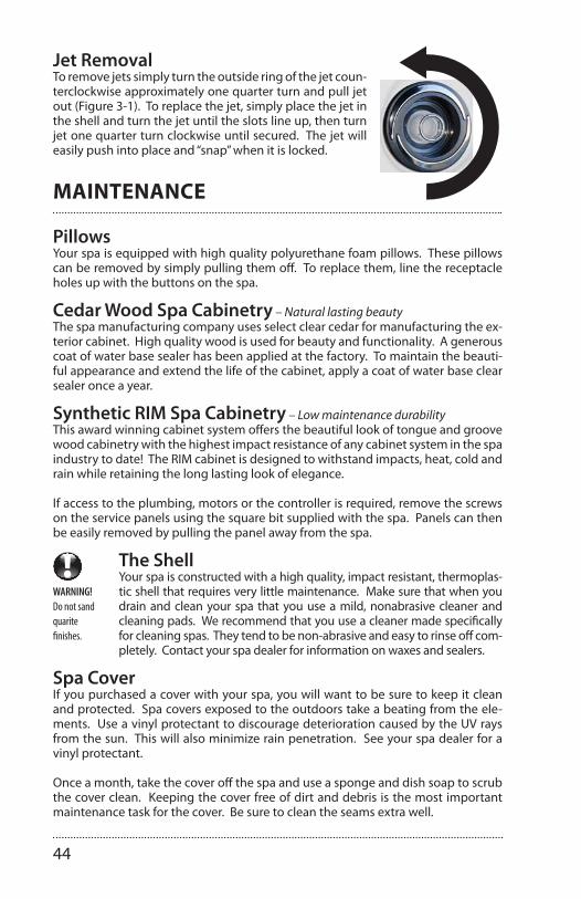
44
Jet RemovalTo remove jets simply turn the outside ring of the jet coun-terclockwise approximately one quarter turn and pull jet out (Figure 3-1). To replace the jet, simply place the jet in the shell and turn the jet until the slots line up, then turn jet one quarter turn clockwise until secured. The jet will easily push into place and “snap” when it is locked.
MAINTENANCE
PillowsYour spa is equipped with high quality polyurethane foam pillows. These pillows can be removed by simply pulling them off. To replace them, line the receptacle holes up with the buttons on the spa.
Cedar Wood Spa Cabinetry – Natural lasting beautyThe spa manufacturing company uses select clear cedar for manufacturing the ex-terior cabinet. High quality wood is used for beauty and functionality. A generous coat of water base sealer has been applied at the factory. To maintain the beauti-ful appearance and extend the life of the cabinet, apply a coat of water base clear sealer once a year.
Synthetic RIM Spa Cabinetry – Low maintenance durabilityThis award winning cabinet system offers the beautiful look of tongue and groove wood cabinetry with the highest impact resistance of any cabinet system in the spa industry to date! The RIM cabinet is designed to withstand impacts, heat, cold and rain while retaining the long lasting look of elegance.
If access to the plumbing, motors or the controller is required, remove the screws on the service panels using the square bit supplied with the spa. Panels can then be easily removed by pulling the panel away from the spa.
WARNING!Do not sand quaritefinishes.
The ShellYour spa is constructed with a high quality, impact resistant, thermoplas-tic shell that requires very little maintenance. Make sure that when you drain and clean your spa that you use a mild, nonabrasive cleaner and cleaning pads. We recommend that you use a cleaner made specifically for cleaning spas. They tend to be non-abrasive and easy to rinse off com-pletely. Contact your spa dealer for information on waxes and sealers.
Spa CoverIf you purchased a cover with your spa, you will want to be sure to keep it clean and protected. Spa covers exposed to the outdoors take a beating from the ele-ments. Use a vinyl protectant to discourage deterioration caused by the UV rays from the sun. This will also minimize rain penetration. See your spa dealer for a vinyl protectant.
Once a month, take the cover off the spa and use a sponge and dish soap to scrub the cover clean. Keeping the cover free of dirt and debris is the most important maintenance task for the cover. Be sure to clean the seams extra well.

45
Your cover comes with screws that are used to fasten the receiving end of the strap locks. Simply align the cover on the spa and stretch out the straps until they are tight. Mark the location of the strap receptacles, then fasten them to the spa skirt with the screws supplied.
WinterizingSince ‘freeze damage’ is not covered under the Limited Warranty, we recom-mend contacting and having a spa professional prepare your spa for winterizing protection. If you live in a climate where winter temperatures are below freezing and power to the spa will be disconnected, follow these procedures for draining:
Winterizing guidelines:1. Add an algaecide to the water and run pumps for half an hour to evenly disperse algaecide.
2. Turn off power to the unit at the circuit breaker.
3. Drain the spa by attaching a garden hose to the open the drain valve. After the spa is empty, remove the hose and leave the drain valve open.
4. For freeze protection – Access motor area by removing the outer front panels to the right and left of the controller panel and unscrew the plumbing collars from the pumps. Leave union couplings disconnected. Vacuum out lines with a wet/dry shop vacuum.
5. Soak up any excess water that drains from motors and associated plumbing with a towel. Keep water and debris out by covering with a rigid spa cover.
6. Before using the spa again, reattach pump couplings, close drain valve, and review startup instructions.
If the spa is to be used during the winter, save energy by turning the temperature down and keeping the spa covered. If the spa reaches freezing temperatures, the main pumps will automatically turn on to circulate the water.

46
Draining The Spa We recommend that you drain and clean your spa no more than 3 or 4 times per year, depending on how frequently you use it and how well you maintain your water. In most cases this simple process will only take about an hour to accomplish.Note: Cabinet styles may vary.
Draining The Spa – Low Profile FloorDrain for low profile floor spas are located on the cabinet.
Step 5: When you are done drain-ing your spa, reverse these steps to close the drain, screw on the cap and push in the valve to the inner-most closed position.
Drain Location: The drain is located in the lower right hand corner of the cabinet under the topside control panel. This position is the inner-most closed position.
Step 3: Screw on a garden hose. Place the other end of the hose in the area you want the water to drain to.
Step 4: Once the hose is in place, push in the hose/drain valve half way in to the middle ‘open drain posi-tion’ and drain your spa.
*Note: if you push it in all the way to the innermost closed position, the water will not drain.
Step 1: Using your hand, pull and slide out the drain plug to the outermost extended closed position.
Step 2: In the outermost ex-tended closed position, unscrew the cap. Water should not drain out in this position.
Innermost closed
position
Middle open
position
Outermost closed
position

47
Drain Location: The drain is located in the center of the Durafloor directly under the topside control panel. This is the innermost closed posi-tion.
Step 3: Open DrainWith the hose attached, turn the round portion of the drain counterclock-wise until it stops, then gently pull the round por-tion (with hose attached) out until you hear a click (approx 1/4”).
Step 4: Close DrainWhen you are done drain-ing your spa, reverse these steps to close the drain (step 3), remove the hose (step 2), screw on the cap (step 1).
Step 1: Remove CapUsing your hand, unscrew the cap to the drain.
Step 2: Attach HoseScrew on a garden hose. Place the other end of the hose in the area you want the water to drain to.
Draining The Spa – High Profile FloorDrain for high profile floor spas are located in the center of the floor under the topside control panel.
We recommend that you drain and clean your spa no less than 3 or 4 times per year, depending on how frequently you use it and how well you main-tain your water. In most cases this simple process will only take about an hour to accomplish.
Detail of drain

48
ENERGY EFFICIENCY GREEN TECHNOLOGY
Providing a greener spa.Your spa manufacturer is strongly committed to protecting the health of our en-vironment and manufacturing energy efficient hot tubs that help to conserve our natural resources. We strive to provide clean air, clean water and recycling solutions – both in how we build our product and in our product itself.
E-Smart TechnologyYour spa is made with ‘e-smart or eco technology’ built into every hot tub to provide a complete en-ergy efficient system. From the initial engineering design stage through our manufacturing, recycling and product usage, we have set a high standard to keep our hot tubs environmentally sound. This symbol sig-nifies the highest energy efficiencies, the smartest engineering detail standards, global environmentally green components and e-cycling sound programs. Energy E�cient
CEC Certi�edRecycling ProgramRecycled ABS Floor
ManufacturingFactory Process
Clean WaterNatural Solutions
Clean AirEco Shell Spray
Certi�edEnergy E�ciency
CEC
Energy E�cient Recycling Program Manufacturing Clean Water Clean AirCerti�ed
CECEnergy EfficientClearwater Spas RTB (reflective thermal barrier) insulation is 12% more energy efficient than spray foam insulation. Our insulation panels re-flect and recycle heat from within the cabinet keeping it warm and dry. Energy E�cient
CEC Certi�edRecycling ProgramRecycled ABS Floor
ManufacturingFactory Process
Clean WaterNatural Solutions
Clean AirEco Shell Spray
Certi�edEnergy E�ciency
CEC
Energy E�cient Recycling Program Manufacturing Clean Water Clean AirCerti�ed
CECCalifornia Energy Commission (CEC) CertifiedAll of Clearwater Spas are certified to California’s Energy Commission (CEC) – the most stringent energy standards in the United States. We not only meet these standards – we exceed them. Energy E�cient
CEC Certi�edRecycling ProgramRecycled ABS Floor
ManufacturingFactory Process
Clean WaterNatural Solutions
Clean AirEco Shell Spray
Certi�edEnergy E�ciency
CEC
Energy E�cient Recycling Program Manufacturing Clean Water Clean AirCerti�ed
CECRecycling & E-cyclingClearwater Spas takes pride in using 100% recycled ABS to fabricate our Durafloors on all of our spas. We also recycle 100% of our wood, plastic and cardboard waste. Energy E�cient
CEC Certi�edRecycling ProgramRecycled ABS Floor
ManufacturingFactory Process
Clean WaterNatural Solutions
Clean AirEco Shell Spray
Certi�edEnergy E�ciency
CEC
Energy E�cient Recycling Program Manufacturing Clean Water Clean AirCerti�ed
CECHealthy Factory ProcessWe are focused on providing healthy and safe solutions in our factory for our employees and our environment. This includes processes for good air quality, recycled and energy efficient components. Energy E�cient
CEC Certi�edRecycling ProgramRecycled ABS Floor
ManufacturingFactory Process
Clean WaterNatural Solutions
Clean AirEco Shell Spray
Certi�edEnergy E�ciency
CEC
Energy E�cient Recycling Program Manufacturing Clean Water Clean AirCerti�ed
CECClean Air FactoryOur Eco-Spray™ process for strengthening every spa shell has 0% sty-rene, no odor and emits no VOC’s (volatile organic compounds) for a clean air environment. Energy E�cient
CEC Certi�edRecycling ProgramRecycled ABS Floor
ManufacturingFactory Process
Clean WaterNatural Solutions
Clean AirEco Shell Spray
Certi�edEnergy E�ciency
CEC
Energy E�cient Recycling Program Manufacturing Clean Water Clean AirCerti�ed
CECClean Water SolutionsWe provide cutting edge clean water solutions to help provide natural alternatives and help reduce the need for chemicals. Salt water, UV-C light, ozone and re-usable filters provide natural clean water solutions.
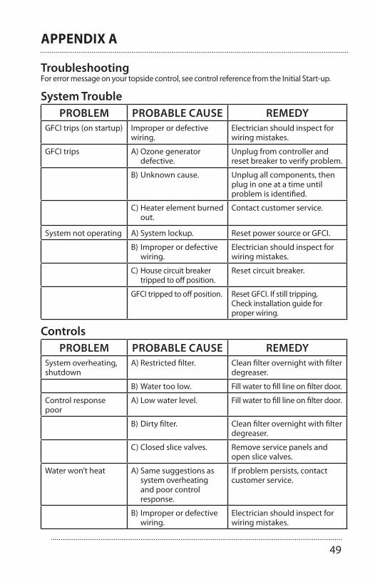
49
APPENDIX A
TroubleshootingFor error message on your topside control, see control reference from the Initial Start-up.
System TroublePROBLEM PROBABLE CAUSE REMEDY
GFCI trips (on startup) Improper or defective wiring.
Electrician should inspect forwiring mistakes.
GFCI trips A) Ozone generator defective.
Unplug from controller andreset breaker to verify problem.
B) Unknown cause. Unplug all components, thenplug in one at a time until problem is identified.
C) Heater element burned out.
Contact customer service.
System not operating A) System lockup. Reset power source or GFCI.
B) Improper or defective wiring.
Electrician should inspect forwiring mistakes.
C) House circuit breaker tripped to off position.
Reset circuit breaker.
GFCI tripped to off position. Reset GFCI. If still tripping,Check installation guide forproper wiring.
ControlsPROBLEM PROBABLE CAUSE REMEDY
System overheating, shutdown
A) Restricted filter. Clean filter overnight with filter degreaser.
B) Water too low. Fill water to fill line on filter door.
Control response poor
A) Low water level. Fill water to fill line on filter door.
B) Dirty filter. Clean filter overnight with filter degreaser.
C) Closed slice valves. Remove service panels and open slice valves.
Water won’t heat A) Same suggestions as system overheating and poor control response.
If problem persists, contact customer service.
B) Improper or defective wiring.
Electrician should inspect for wiring mistakes.

50
PumpsPROBLEM PROBABLE CAUSE REMEDY
Noisy pump or motor A) Clogged filter or pump inlets.
Clean filter, filter basket and pump inlets
B) Low water level. Fill water to fill line on filter door.
C) Slice valves not open. Remove service panels and open slice valves.
D) Debris in pump(s). Contact customer service.
E) Damaged or worn motor bearings.
Contact customer service.
Motor not functioning A) Cord unplugged or damaged.
Check wiring to controller. Contact customer service.
B) Motor overloaded. Let motor cool for one hour, open all jets. Motor will reset automatically.
C) Defective start switch. Contact customer service.
D) Blockage in line. Contact customer service.
E) Kink in hose. Remove service panels and check for a kinked hose.
F) Slice valves not open. Remove service panels and open slice valves.
G) Blown fuse. Check fuses. Replace if bad.
JetsPROBLEM PROBABLE CAUSE REMEDY
Rotating jets won’t rotate
Debris in jet housing. See ‘Cleaning the rotating jets’ section of the JETS chapter.
WaterPROBLEM PROBABLE CAUSE REMEDY
Water leak A) Compression fittings (unions) have loosened.
Tighten fittings.
B) Leak at barbed fitting. Cut off hose clamp through the raised ear portion and reseat hose. Reconnect with a new hose clamp or a ‘worm drive clamp’.
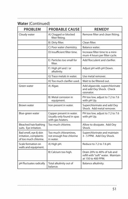
51
Water (Continued)PROBLEM PROBABLE CAUSE REMEDY
Cloudy water A) Clogged or blocked filter fitting.
Remove filter and clean fitting.
B) Dirty filter. Clean filter.
C) Poor water chemistry. Balance water.
D) Insufficient filter time. Increase filter time to a mini-mum 4 hours per filter cycle.
E) Particles too small for filter.
Add flocculent and clarifier.
F) High pH and / or alkalinity.
Adjust pH with pH Down.
G) Trace metals in water. Use metal remover.
H) Too much clarifier used. Wait to be filtered out.
Green water A) Algae. Add algaecide, superchlorinate and add Oxy Shock. Check ozonator.
B) Metal corrosion in equipment.
PH too low, adjust to 7.2 to 7.6 with pH Up.
Brown water Iron present in water. Superchlorinate and add Oxy Shock. Add metal remover.
Blue-green water Copper present in water. Usually only found in spas with gas heaters.
PH too low, adjust to 7.2 to 7.6 with pH Up.
Bleached hair/bathing suits. Eye irritation.
Too much chlorine. Allow to dissipate. Add Oxy Shock.
Bad smell, eye & skin irritation, complaints of too much chlorine.
Too much chloramines, not enough free chlorine in water.
Superchlorinate and maintain 3 - 5 PPM. Add Oxy Shock.
Scale formation on walls and equipment.
A) High pH. Reduce to 7.2 to 7.6 pH.
B) Calcium too high. Drain 20% to 40% of tub and refill with “soft” water. Maintain at 150 to 400 PPM.
pH fluctuates radically Total alkalinity out of balance.
Balance alkalinity.

52
FAQ’S - FREQUENTLY ASKED QUESTIONS
Q: Why is my spa not heating?A: Check which mode you are in: standard, sleep or economy. See ‘Topside Control’ . Standard and Economy mode will allow temperature to drop 10 degrees. Sleep mode will allow temperature to drop 20 degrees.
Q: The system is receiving proper voltage, why doesn’t anything function?A: 1. Check for blown fuses, burn marks or signs of tampering in the box. 2. Power down the spa, and reset the GFCI. If problem persists, contact customer service for tech support.
Q: What does the ozone generator do?A: An ozonator purifies naturally. It produces an active oxygen that attacks bacteria at microscopic levels reducing the amount of chemicals needed for perfect water. Ozone is also useful in coagulation of metals an other contaminants found in some areas.
Q: How do I know if my ozonator is working?A: During a filter cycle, a green LED light on the ozonator will light and bubbles will move through the clear water line that connects to the ozonator.
Q: How do I fill the spa with water?A: 1. Place your garden hose into the filter housing. This will ensure that air bubbles are removed from the lines while you fill the spa. 2. Turn the water on so that most of the water enters through the filter chamber. 3. Fill the water to the proper level – half way up the filter housing.
Q: How do I drain the spa?A: See instructions ‘Draining The Spa’. > Drain Location: The drain is located in the center of the floor directly under the topside control panel. This is the innermost closed position. 1. Remove Cap. Using your hand, unscrew the cap to the drain. 2. Attach Hose. Screw on a garden hose. Place the other end of the hose in the area you want the water to drain to. 3. Open Drain. With the hose attached, turn the round portion of the drain counterclockwise until it stops, then gently pull the round portion (with hose attached) out until you hear a click (approx 1/4”). 4. Close Drain. When you are done draining your spa, reverse these steps to close the drain (step 3), remove the hose (step 2), screw on the cap (step 1).

53
NOTES:

54
NOTES:
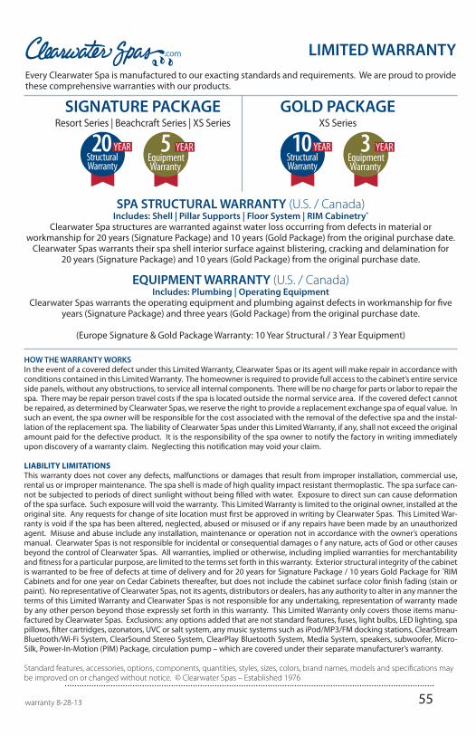
55
HOW THE WARRANTY WORKSIn the event of a covered defect under this Limited Warranty, Clearwater Spas or its agent will make repair in accordance with conditions contained in this Limited Warranty. The homeowner is required to provide full access to the cabinet’s entire service side panels, without any obstructions, to service all internal components. There will be no charge for parts or labor to repair the spa. There may be repair person travel costs if the spa is located outside the normal service area. If the covered defect cannot be repaired, as determined by Clearwater Spas, we reserve the right to provide a replacement exchange spa of equal value. In such an event, the spa owner will be responsible for the cost associated with the removal of the defective spa and the instal-lation of the replacement spa. The liability of Clearwater Spas under this Limited Warranty, if any, shall not exceed the original amount paid for the defective product. It is the responsibility of the spa owner to notify the factory in writing immediately upon discovery of a warranty claim. Neglecting this notification may void your claim.
LIABILITY LIMITATIONSThis warranty does not cover any defects, malfunctions or damages that result from improper installation, commercial use, rental us or improper maintenance. The spa shell is made of high quality impact resistant thermoplastic. The spa surface can-not be subjected to periods of direct sunlight without being filled with water. Exposure to direct sun can cause deformation of the spa surface. Such exposure will void the warranty. This Limited Warranty is limited to the original owner, installed at the original site. Any requests for change of site location must first be approved in writing by Clearwater Spas. This Limited War-ranty is void if the spa has been altered, neglected, abused or misused or if any repairs have been made by an unauthorized agent. Misuse and abuse include any installation, maintenance or operation not in accordance with the owner’s operations manual. Clearwater Spas is not responsible for incidental or consequential damages o f any nature, acts of God or other causes beyond the control of Clearwater Spas. All warranties, implied or otherwise, including implied warranties for merchantability and fitness for a particular purpose, are limited to the terms set forth in this warranty. Exterior structural integrity of the cabinet is warranted to be free of defects at time of delivery and for 20 years for Signature Package / 10 years Gold Package for *RIM Cabinets and for one year on Cedar Cabinets thereafter, but does not include the cabinet surface color finish fading (stain or paint). No representative of Clearwater Spas, not its agents, distributors or dealers, has any authority to alter in any manner the terms of this Limited Warranty and Clearwater Spas is not responsible for any undertaking, representation of warranty made by any other person beyond those expressly set forth in this warranty. This Limited Warranty only covers those items manu-factured by Clearwater Spas. Exclusions: any options added that are not standard features, fuses, light bulbs, LED lighting, spa pillows, filter cartridges, ozonators, UVC or salt system, any music systems such as iPod/MP3/FM docking stations, ClearStream Bluetooth/Wi-Fi System, ClearSound Stereo System, ClearPlay Bluetooth System, Media System, speakers, subwoofer, Micro-Silk, Power-In-Motion (PIM) Package, circulation pump – which are covered under their separate manufacturer’s warranty.
Standard features, accessories, options, components, quantities, styles, sizes, colors, brand names, models and specifications may be improved on or changed without notice. © Clearwater Spas – Established 1976
warranty 8-28-13
LIMITED WARRANTYEvery Clearwater Spa is manufactured to our exacting standards and requirements. We are proud to provide these comprehensive warranties with our products.
SPA STRUCTURAL WARRANTY (U.S. / Canada)Includes: Shell | Pillar Supports | Floor System | RIM Cabinetry*
Clearwater Spa structures are warranted against water loss occurring from defects in material or workmanship for 20 years (Signature Package) and 10 years (Gold Package) from the original purchase date.
Clearwater Spas warrants their spa shell interior surface against blistering, cracking and delamination for 20 years (Signature Package) and 10 years (Gold Package) from the original purchase date.
EQUIPMENT WARRANTY (U.S. / Canada)Includes: Plumbing | Operating Equipment
Clearwater Spas warrants the operating equipment and plumbing against defects in workmanship for five years (Signature Package) and three years (Gold Package) from the original purchase date.
(Europe Signature & Gold Package Warranty: 10 Year Structural / 3 Year Equipment)
SIGNATURE PACKAGEResort Series | Beachcraft Series | XS Series
GOLD PACKAGEXS Series
StructuralWarranty
StructuralWarranty

Clearwater Spas environmental commitmentbegins with our exclusive E-Smart™ Technology
spa manual, US/Canada, 1.1.14
Energy E�cient Recycling Program Manufacturing Clean Water Clean AirCerti�ed
CEC