Clearfire Condensing Boiler Model CFC - CB Portal
270
Manual Part No. 750-263 07/2008 Clearfire Condensing Boiler Model CFC Gas High Efficiency Boiler Operation, Service, and Parts Manual CLEAVER-BROOKS MILWAUKEE, WISCONSIN ANSI STANDARD Z21.13b-2004 — CSA 4.9b-2004 LOW PRESSURE BOILER ANSI STANDARD Z21.13b-2005 — CSA 4.9b-2005
Transcript of Clearfire Condensing Boiler Model CFC - CB Portal

ClearfireCondensing Boiler
Model CFCGas High Efficiency Boiler
Operation, Service,and Parts Manual
Table Of Contents
Manual Part No. 750-263
ANSI S
07/2008
CLEAVER-BROOKS MILWAUKEE, WISCONSIN
TANDARD Z21.13b-2004 — CSA 4.9b-2004 LOW PRESSURE BOILER
ANSI STANDARD Z21.13b-2005 — CSA 4.9b-2005

2
! DANGERWARNINGIf the information in this manual is not fol-lowed exactly, a fire or explosion may re-sult causing property damage, personalinjury or loss of life.
— Do not store or use gasoline or otherflammable vapors and liquids in the vicin-ity of this or any other appliance.
— WHAT TO DO IF YOU SMELL GAS• Do not try to light any appliance.• Do not touch any electrical switch; do
not use any phone in your building.• Immediately call your gas supplier
from a neighbor's phone. Follow the gas supplier's instructions.
• If you cannot reach your gas supplier, call the fire department.
— Installation and service must be per-formed by a qualified Cleaver-Brooks, service agency or the gas supplier.
Improper installation, adjustment serviceor maintenance can cause equipmentdamage, personal injury or death. Referto the Operation and Maintenance manu-al provided with the boiler. Installationand service must be performed by a qual-ified Cleaver-Brooks service provider.
! DANGERWARNING
! DANGERWARNING
Be sure the fuel supply which the boilerwas designed to operate on is the sametype as specified on the boiler nameplate.
! DANGERWARNING
Should overheating occur or the gas sup-ply valve fail to shut off. Do not turn off ordisconnect the electrical supply to theboiler. Instead turn off the gas supply at alocation external to the boiler.
! DANGERWARNING
Do not use this boiler if any part has beenunder water. Immediately call your Cleav-er-Brooks service representative to in-spect the boiler and to replace any part ofthe control system and any gas controlwhich has been under water.
! DANGERWARNINGTo minimize the possibility of serious per-sonal injury, fire or damage to the equip-ment, never violate the following safety rules. — Always keep the area around the boiler free of combustible materials, gasoline, and other flammable liquids and vapors— Never cover the boiler, lean anything against it, stand on it or in any way block the flow of fresh air to the boiler. This manual must be maintained in legi-
ble condition and kept adjacent to theboiler or in a safe place for future refer-ence. Contact your local Cleaver-Brooksrepresentative if additional manuals arerequired.
Notice
Where required by the authority havingjurisdiction, the installation must conformto the Standard for Controls and SafetyDevices for Automatically Fired Boilers,ANSI/ASME CSD-1.
Notice

3
! DANGERWARNINGA hot water boiler installed above radia-tion level or as required by the Authorityhaving jurisdiction, must be provided witha low water cutoff device either as a partof the boiler or at the time of boiler instal-lation.
The installation must conform to the re-quirements of the authority having juris-diction or, in the absence of suchrequirements, to the National Fuel GasCode, ANSI Z223.1 and/or CAN/CSAB149 Installation Codes.
! DANGERWARNING
The boiler and its individual shutoff valvemust be disconnected from the gas sup-ply piping system during any pressuretesting of that system at test pressures inexcess of 1/2 psi (3.5 kPa).
! DANGERWARNING
Notes

4
TO: Owners, Operators and/or Maintenance Personnel
This operating manual presents information that will help to properly operate and care for the equipment. Study its contents carefully. The unit will provide good service and continued operation if proper operating and maintenance instructions are fol-lowed. No attempt should be made to operate the unit until the principles of operation and all of the components are thoroughly understood. Failure to follow all applicable instructions and warnings may result in severe personal injury or death.
It is the responsibility of the owner to train and advise not only his or her personnel, but the contractors' personnel who are ser-vicing, repairing or operating the equipment, in all safety aspects.
Cleaver-Brooks equipment is designed and engineered to give long life and excellent service on the job. The electrical and mechanical devices supplied as part of the unit were chosen because of their known ability to perform; however, proper oper-ating techniques and maintenance procedures must be followed at all times. Although these components afford a high degree of protection and safety, operation of equipment is not to be considered free from all dangers and hazards inherent in handling and firing of fuel.
Any "automatic" features included in the design do not relieve the attendant of any responsibility. Such features merely free him of certain repetitive chores and give him more time to devote to the proper upkeep of equipment.
It is solely the operator’s responsibility to properly operate and maintain the equipment. No amount of written instructions can replace intelligent thinking and reasoning and this manual is not intended to relieve the operating personnel of the responsibility for proper operation. On the other hand, a thorough understanding of this manual is required before attempting to operate, main-tain, service, or repair this equipment.
Because of state, local, or other applicable codes, there are a variety of electric controls and safety devices which vary consid-erably from one boiler to another. This manual contains information designed to show how a basic burner operates.
Operating controls will normally function for long periods of time and we have found that some operators become lax in their daily or monthly testing, assuming that normal operation will continue indefinitely. Malfunctions of controls lead to uneco-nomical operation and damage and, in most cases, these conditions can be traced directly to carelessness and deficiencies in testing and maintenance.
It is recommended that a boiler room log or record be maintained. Recording of daily, weekly, monthly and yearly maintenance activities and recording of any unusual operation will serve as a valuable guide to any necessary investigation.
Most instances of major boiler damage are the result of operation with low water. We cannot emphasize too strongly the need for the operator to periodically check his low water controls and to follow good maintenance and testing practices. Cross-con-necting piping to low water devices must be internally inspected periodically to guard against any stoppages which could ob-struct the free flow of water to the low water devices. Float bowls of these controls must be inspected frequently to check for the presence of foreign substances that would impede float ball movement.
The waterside condition of the pressure vessel is of extreme importance. Waterside surfaces should be inspected frequently to check for the presence of any mud, sludge, scale or corrosion.
The services of a qualified water treating company or a water consultant to recommend the proper boiler water treating practices are essential.
The operation of this equipment by the owner and his or her operating personnel must comply with all requirements or regula-tions of his insurance company and/or other authority having jurisdiction. In the event of any conflict or inconsistency between such requirements and the warnings or instructions contained herein, please contact Cleaver-Brooks before proceeding.
DO NOT OPERATE, SERVICE, OR REPAIR THIS EQUIPMENT UNLESS YOU FULLY UNDERSTAND ALL APPLICABLE SECTIONS OF THIS MANUAL.
DO NOT ALLOW OTHERS TO OPERATE, SERVICE, OR REPAIR THIS EQUIPMENT UNLESS THEY FUL-LY UNDERSTAND ALL APPLICABLE SECTIONS OF THIS MANUAL.
FAILURE TO FOLLOW ALL APPLICABLE WARNINGS AND INSTRUCTIONS MAY RESULT IN SEVEREPERSONAL INJURY OR DEATH.
! DANGERWARNING

TABLE OF CONTENTSSection 1 — Introduction
Clearfire Features and Benefits . . . . . . . . . . . . . . . . . . . . . . . . . . . . . 1-2Standard Equipment . . . . . . . . . . . . . . . . . . . . . . . . . . . . . . . . . . . . . 1-3
The Boiler . . . . . . . . . . . . . . . . . . . . . . . . . . . . . . . . . . . . . . . . . 1-3The Burner . . . . . . . . . . . . . . . . . . . . . . . . . . . . . . . . . . . . . . . . . 1-3Burner Gas Train . . . . . . . . . . . . . . . . . . . . . . . . . . . . . . . . . . . . 1-3Control . . . . . . . . . . . . . . . . . . . . . . . . . . . . . . . . . . . . . . . . . . . 1-4Component/Connection Locations . . . . . . . . . . . . . . . . . . . . . . . . . 1-4Optional Equipment . . . . . . . . . . . . . . . . . . . . . . . . . . . . . . . . . . 1-4
Section 2 — InstallationAssembly . . . . . . . . . . . . . . . . . . . . . . . . . . . . . . . . . . . . . . . . . . . . 2-3
Packaging . . . . . . . . . . . . . . . . . . . . . . . . . . . . . . . . . . . . . . . . . . 2-3Boiler room . . . . . . . . . . . . . . . . . . . . . . . . . . . . . . . . . . . . . . . . . 2-3Mounting legs . . . . . . . . . . . . . . . . . . . . . . . . . . . . . . . . . . . . . . . . 2-4Insulation . . . . . . . . . . . . . . . . . . . . . . . . . . . . . . . . . . . . . . . . . . . 2-5Casing assembly . . . . . . . . . . . . . . . . . . . . . . . . . . . . . . . . . . . . . . 2-6Base mounting . . . . . . . . . . . . . . . . . . . . . . . . . . . . . . . . . . . . . . . 2-8
Flue gas / combustion air connections . . . . . . . . . . . . . . . . . . . . . . . . 2-9Water Treatment . . . . . . . . . . . . . . . . . . . . . . . . . . . . . . . . . . . . . . . 2-9Boiler Room . . . . . . . . . . . . . . . . . . . . . . . . . . . . . . . . . . . . . . . . . . 2-9Gas Connections . . . . . . . . . . . . . . . . . . . . . . . . . . . . . . . . . . . . . . 2-10
General . . . . . . . . . . . . . . . . . . . . . . . . . . . . . . . . . . . . . . . . . . . 2-10Gas train components . . . . . . . . . . . . . . . . . . . . . . . . . . . . . . . . . 2-10Gas pressure requirements . . . . . . . . . . . . . . . . . . . . . . . . . . . . . . 2-10Gas piping . . . . . . . . . . . . . . . . . . . . . . . . . . . . . . . . . . . . . . . . . 2-11Gas supply pipe sizing . . . . . . . . . . . . . . . . . . . . . . . . . . . . . . . . . 2-12Gas header . . . . . . . . . . . . . . . . . . . . . . . . . . . . . . . . . . . . . . . . 2-18
Boiler Water Piping . . . . . . . . . . . . . . . . . . . . . . . . . . . . . . . . . . . . 2-20General . . . . . . . . . . . . . . . . . . . . . . . . . . . . . . . . . . . . . . . . . . . 2-20Water temperature sensors . . . . . . . . . . . . . . . . . . . . . . . . . . . . . . 2-20Safety valve . . . . . . . . . . . . . . . . . . . . . . . . . . . . . . . . . . . . . . . . 2-20Pressure drop curves . . . . . . . . . . . . . . . . . . . . . . . . . . . . . . . . . . 2-20
Condensate removal and treatment . . . . . . . . . . . . . . . . . . . . . . . . . 2-27Condensate Tank Installation . . . . . . . . . . . . . . . . . . . . . . . . . . . . . . 2-27
Condensate tank setup options . . . . . . . . . . . . . . . . . . . . . . . . . . . 2-28Condensate take-off and neutralization . . . . . . . . . . . . . . . . . . . . . 2-28Condensate discharge into local drain . . . . . . . . . . . . . . . . . . . . . . 2-28Piping treated condensate to drain . . . . . . . . . . . . . . . . . . . . . . . . 2-28Installation . . . . . . . . . . . . . . . . . . . . . . . . . . . . . . . . . . . . . . . . . 2-29
Condensate piping for multiple boilers . . . . . . . . . . . . . . . . . . . . . . . 2-30Electrical Connections . . . . . . . . . . . . . . . . . . . . . . . . . . . . . . . . . . . 2-31Wiring Diagrams . . . . . . . . . . . . . . . . . . . . . . . . . . . . . . . . . . . . . . . 2-33
Section 3 — Stack and Intake Vent Sizing and InstallationVenting Connections - General . . . . . . . . . . . . . . . . . . . . . . . . . . . . . . 3-2
Appliance Categories . . . . . . . . . . . . . . . . . . . . . . . . . . . . . . . . . . . 3-2Vent Stack . . . . . . . . . . . . . . . . . . . . . . . . . . . . . . . . . . . . . . . . . . 3-2Vent Terminal Location . . . . . . . . . . . . . . . . . . . . . . . . . . . . . . . . . 3-3
Horizontal Thru-Wall Venting / Inside Combustion Air . . . . . . . . . . . . . . 3-6Installation . . . . . . . . . . . . . . . . . . . . . . . . . . . . . . . . . . . . . . . . . . 3-6Horizontal Thru-Wall Stack Vent Termination . . . . . . . . . . . . . . . . . . 3-7
Horizontal Thru-Wall Venting / Direct Vent Combustion Air . . . . . . . . . . 3-8Installation . . . . . . . . . . . . . . . . . . . . . . . . . . . . . . . . . . . . . . . . . . 3-8Horizontal Thru-Wall Stack Vent Termination . . . . . . . . . . . . . . . . . . 3-9
Vertical Venting / Inside Combustion Air . . . . . . . . . . . . . . . . . . . . . . 3-10Vertical Venting / Direct Vent Combustion Air . . . . . . . . . . . . . . . . . . . 3-11
5

Section 4 — CommissioningOperating Conditions . . . . . . . . . . . . . . . . . . . . . . . . . . . . . . . . . . . . 4-2Filling Boiler . . . . . . . . . . . . . . . . . . . . . . . . . . . . . . . . . . . . . . . . . . 4-2Control Setpoints . . . . . . . . . . . . . . . . . . . . . . . . . . . . . . . . . . . . . . . 4-2Model CFC Boiler / Burner Controller . . . . . . . . . . . . . . . . . . . . . . . . . 4-2CB Falcon Display/Operator Interface . . . . . . . . . . . . . . . . . . . . . . . . . 4-3
Lockouts and Alerts . . . . . . . . . . . . . . . . . . . . . . . . . . . . . . . . . . . 4-5Controller Configuration . . . . . . . . . . . . . . . . . . . . . . . . . . . . . . . . . . 4-5
Changing Parameter Settings . . . . . . . . . . . . . . . . . . . . . . . . . . . 4-11Burner Sequence . . . . . . . . . . . . . . . . . . . . . . . . . . . . . . . . . . . . . . 4-12Fan Speed Settings . . . . . . . . . . . . . . . . . . . . . . . . . . . . . . . . . . . . . 4-13Initial start-up procedure . . . . . . . . . . . . . . . . . . . . . . . . . . . . . . . . . 4-13Post start-up checkout procedure . . . . . . . . . . . . . . . . . . . . . . . . . . . 4-20
Section 5 — Service and MaintenanceCleaning Procedure / Disassembly ...................................................... 5-2Condensate Neutralization ................................................................. 5-3Assembly ........................................................................................ 5-3Ignition Electrode and Flame Rod ....................................................... 5-4Troubleshooting ................................................................................ 5-4
Section 6 — PartsAppendix A — CB Falcon Hydronic ControlAppendix B — Falcon Display/Operator InterfaceAppendix C — Gas Valve
6

Milwaukee, Wisconsin
www.cleaver-brooks.com
Chapter 1Introduction
CFC Features and Benefits . . . . . . . . . . . . . . . . . . . . . . . . . . . . . . . . 1-2Standard Equipment . . . . . . . . . . . . . . . . . . . . . . . . . . . . . . . . . . . . 1-3
The Boiler . . . . . . . . . . . . . . . . . . . . . . . . . . . . . . . . . . . . . . . . . 1-3The Burner . . . . . . . . . . . . . . . . . . . . . . . . . . . . . . . . . . . . . . . . 1-3Burner Gas Train . . . . . . . . . . . . . . . . . . . . . . . . . . . . . . . . . . . . 1-3Control . . . . . . . . . . . . . . . . . . . . . . . . . . . . . . . . . . . . . . . . . . . 1-4Component/Connection Locations . . . . . . . . . . . . . . . . . . . . . . . . . 1-4Optional Equipment . . . . . . . . . . . . . . . . . . . . . . . . . . . . . . . . . . 1-4

Chapter 1 — Introduction
A. CFC FEATURES AND BENEFITSCompact Firetube Design (Figure 1-1 & Figure 1-2)The CFC boiler is a single pass down fired durable Firetube boiler.The extended heating surface tubes provide for very high levels ofperformance in a compact space. The boiler is designed to firenatural gas or propane.
High Efficiency (Figure 1-3)With the extended heating surface tubes the boiler can produce fuelto water efficiency of up to 98% depending upon operatingconditions.
Advanced ConstructionConstructed to ASME standards and util izing AluFer tubetechnology in a single-pass design, the CFC Boiler will provide manyyears of trouble free service. Single-pass design provides excellentthermal shock protection.
Ease of MaintenanceThe steel enclosures are readily removable for access to all keycomponents. A flip down step and hinged burner door provideaccess to all key components.
Quality ConstructionASME construction ensures high quality design, safety, andreliability.
ISO 9001 certified manufacturing process ensures the highestdegree of manufacturing standards is always followed.
Full ModulationThe burner and combustion fan modulate to provide only theamount of heat required, providing quiet and efficient operationunder all conditions.
Premix TechnologyThe ClearFire-C Boiler utilizes "Premix" technology to mix both fueland combustion air prior to entering the firing chamber. Thistechnology provides clean, efficient combustion with very lowemission levels.
Designed For Heating ApplicationsThe pressure vessel is constructed of durable ASTM Graded Steeland Stainless Steel materials to provide many years of operating life.
The vessel is designed to prevent hot spots and has no minimumflow requirements; required for vessel stress protection.
Figure 1-1 CFC Boiler
Figure 1-2 CFC Cutaway
Premix Burner
Insulation
Pressure Cabinet
On/Off
Control
Control
VesselSwitch
Panel
Display
Figure 1-3 AluFer Tube Cross Section
1-2 Part No. 750-263

Chapter 1 — Introduction
B.STANDARD EQUIPMENT1. The BoilerThe boiler is designed for a Maximum Allowable Working Pressure(MAWP) of 60 psig (4.1 Bar) in accordance with the ASME Codefor Low Pressure Section IV Hot Water Boilers and is stampedaccordingly. Operating pressure shall be less than 54 psig (3.72Bar).
The vessel is mounted on a steel base with insulation & casingprovided including trim and controls. Trim and controls includesafety relief valve, pressure/temperature gauge, probe type lowwater control, and CB Falcon hydronic boiler control with associatedsensors..
2. The Burner (See Figure 1-4)
Incorporating "premix" technology, the burner utilizes a venturi, dualsafety shutoff-single body gas valve, variable speed blower, andFecralloy metal fiber burner head.
With the integral variable speed combustion air fan, 5:1 turndownis provided.
Combustion canister of the burner is constructed of a Fecralloy-metal fiber for solid body radiation of the burner flame, whichprovides low emissions.
At maximum firing rate, the sound level of the burner is less than70 dBA, measured in front of the boiler at a distance of 3 feet.
Provision for direct vent combustion is furnished.
Combustion Air Proving Switch and High Air Pressure Switch.
3. Burner Gas Train (See Figure 1-5 & Figure 1-6)
The gas train assembly is provided in accordance with CSAcertification and ASME CSD-1. The gas train assembly is factoryassembled and wired, consisting of the following components:
A. Low Gas Pressure Switch - manual resetB. High Gas Pressure Switch - manual resetC. Single body, dual safety shutoff gas valve with integral trim
regulatorD. Integral VenturiE. Manual Shutoff Ball ValveF. CSD-1 Test Cocks
Figure 1-4
Figure 1-5 Standard Gas Train, CSA and ASME CSD-1
High Gas Pressure Switch
Low Gas Pressure Switch
Manual Shutoff
Test Cock
Part No. 750-263 1-3

Chapter 1 — Introduction
4. Control (See Figure 1-7)
The CB Falcon hydronic control is an integrated burner managementand modulation control with a touch-screen display/operatorinterface.
The controller is capable of the following functions:
• Two (2) heating loops with PID load control.
• Burner sequencing with safe start check, pre-purge, direct spark ignition, and post purge.
• Electronic ignition.
• Flame Supervision.
• Safety shutdown with time-stamped display of lockout condition.
• Variable speed control of the combustion fan.
• Supervision of low and high gas pressure, air proving, stack back pressure, high limit, and low water.
• First-out annunciator.
• Real-time data trending.
• (3) pump/auxiliary relay outputs.
• Modbus communication capability.
• Outdoor temperature reset.
5. Component/Connection LocationsFigure 1-8 shows the CFC component orientation and heat flowpath. Note the downfired design of the burner and the orientation ofthe hot water outlet and return connections. The return waterconnection is at the bottom of the vessel and the hot water outlet isnear the top.
Figure 1-9 shows the locations of the safety valve and low watercutoff. Figure 1-10 shows the supply and return connections andthe location of the return water temperature sensor. Looking at thetop of the boiler, near the rear, Figure 1-11 shows the three holesensor well for the outlet temperature sensor.
Figure 1-6 Standard Gas Train Components per CSA and ASME
CSD-1
HGPS
LGPS
GAS VALVE
TEST COCK
Figure 1-7 Control panel (hinged access panel open)
1-4 Part No. 750-263

Chapter 1 — Introduction
When standing at the back of the boiler, the stack can be connectedon the right side of the boiler (Figure 1-12) or on the left side (Figure1-13). Refer to Chapter 3 of this manual for recommended ventsizes and lengths for the specific boiler installation.
6. Optional EquipmentCertain options may have been supplied with the boiler that arerelative to the project requirements if these options were specifiedwith the boiler at the time of order entry. Also, some options mayhave been provided [by others] that are not part of Cleaver-Brooksscope of supply. In either case, the Cleaver-Brooks authorizedrepresentative should be consulted for project specifics.
These are the options that are available for the CFC boiler fromCleaver-Brooks:
A. Reusable air filter.B. Condensate neutralization treatment tank assembly -
consists of neutralizing media, filter, and PVC condensateholding tank. This assembly is mounted beneath the boilerand is further described in Chapter 2.
C. Outside air intake for direct vent combustion.D. Outdoor temperature sensor for indoor/outdoor control.E. Shipped loose Auxiliary Low Water Control for field piping
by others into the system piping.F. Alarm Horn for safety shutdown.G. Relays for output signal for burner on, fuel valve open.H. Stack Thermometer.I. Stack temperature limit-sensor.J. Common condensate drain trap.
Table 1-1 Model CFC Water Temperature DataMinimum supply temp. 33oFMaximum operating temp. 194oFMaximum design temp. 210oF
Part No. 750-263 1-5

Chapter 1 — Introduction
Figure 1-8 CFC Heat Flow and Component Orientation
Combustion Fan and Premix Gas ValveAssembly Burner
Head
Control &Panel
“Finned” High Efficiency AluFerTubes
ASME CodePressure VesselFlue Gas
Outlet
Cold WaterReturn
Hot WaterOutlet
Safety Relief Valve
Condensate DrainCleaning Cover
Filling and Draining cock
Insulation Mat
ElectrodeIgnition andFlame Rod
BurnerCanister
1-6 Part No. 750-263

Chapter 1 — Introduction
Figure 1-9 Boiler Controls
Figure 1-10 Return Temperature Mounting
Low Water Cutoff
Safety Valve(shipped loose)
Probe
Auto air vent(optional; shipped loose)
Return Water
SensorReturn Water In
Temperature
Water SideInspection Port
Part No. 750-263 1-7

Chapter 1 — Introduction
The stack can be mounted on the right (Figure 1-12) or left (Figure1-13) side on the back of the boiler base.
The flue gas duct sizes may be reduced at the vent connection.
See also Chapter 4 - Stack and Intake Vent Sizing and Installation.
.
Figure 1-11 Temperature Sensor, Top of Pressure Vessel
Figure 1-12 Stack Right Side (viewed from rear)
Figure 1-13 Stack Left Side (viewed from rear)
HotWaterOut
Return WaterIn
1-8 Part No. 750-263

Milwaukee, Wisconsin
www.cleaver-brooks.com
Section 2
InstallationAssembly . . . . . . . . . . . . . . . . . . . . . . . . . . . . . . . . . . . . . . . . . . . . 2-3
Packaging . . . . . . . . . . . . . . . . . . . . . . . . . . . . . . . . . . . . . . . . . . 2-3Boiler room . . . . . . . . . . . . . . . . . . . . . . . . . . . . . . . . . . . . . . . . . 2-3Mounting legs . . . . . . . . . . . . . . . . . . . . . . . . . . . . . . . . . . . . . . . . 2-4Insulation . . . . . . . . . . . . . . . . . . . . . . . . . . . . . . . . . . . . . . . . . . 2-4Casing assembly . . . . . . . . . . . . . . . . . . . . . . . . . . . . . . . . . . . . . . 2-6Base mounting . . . . . . . . . . . . . . . . . . . . . . . . . . . . . . . . . . . . . . . 2-8
Flue gas/combustion air connections. . . . . . . . . . . . . . . . . . . . . . . . . . 2-9Water treatment. . . . . . . . . . . . . . . . . . . . . . . . . . . . . . . . . . . . . . . 2-9Boiler Room. . . . . . . . . . . . . . . . . . . . . . . . . . . . . . . . . . . . . . . . . . 2-9Gas Connections . . . . . . . . . . . . . . . . . . . . . . . . . . . . . . . . . . . . . . 2-10
General . . . . . . . . . . . . . . . . . . . . . . . . . . . . . . . . . . . . . . . . . . . 2-10Gas train components . . . . . . . . . . . . . . . . . . . . . . . . . . . . . . . . . 2-10Gas pressure requirements . . . . . . . . . . . . . . . . . . . . . . . . . . . . . 2-10Gas piping . . . . . . . . . . . . . . . . . . . . . . . . . . . . . . . . . . . . . . . . . 2-11Gas supply pipe sizing . . . . . . . . . . . . . . . . . . . . . . . . . . . . . . . . 2-12Gas header . . . . . . . . . . . . . . . . . . . . . . . . . . . . . . . . . . . . . . . . 2-18
Boiler water piping . . . . . . . . . . . . . . . . . . . . . . . . . . . . . . . . . . . . . 2-20General . . . . . . . . . . . . . . . . . . . . . . . . . . . . . . . . . . . . . . . . . . . 2-20Water temperature sensors . . . . . . . . . . . . . . . . . . . . . . . . . . . . . . 2-20Safety valve . . . . . . . . . . . . . . . . . . . . . . . . . . . . . . . . . . . . . . . . 2-20Pressure drop curves . . . . . . . . . . . . . . . . . . . . . . . . . . . . . . . . . . 2-20
Condensate removal and treatment . . . . . . . . . . . . . . . . . . . . . . . 2-27Condensate Tank Installation . . . . . . . . . . . . . . . . . . . . . . . . . . . . . 2-27
Condensate tank setup options . . . . . . . . . . . . . . . . . . . . . . . . . . 2-28Condensate take-off and neutralization . . . . . . . . . . . . . . . . . . . . . 2-28Condensate discharge into local drain . . . . . . . . . . . . . . . . . . . . 2-28Piping treated condensate to drain . . . . . . . . . . . . . . . . . . . . . . 2-28Installation . . . . . . . . . . . . . . . . . . . . . . . . . . . . . . . . . . . . . . . . 2-29
Condensate piping for multiple boilers . . . . . . . . . . . . . . . . . . . . . . . 2-30Electrical connections . . . . . . . . . . . . . . . . . . . . . . . . . . . . . . . . . 2-31Wiring Diagrams . . . . . . . . . . . . . . . . . . . . . . . . . . . . . . . . . . . . . . 2-33

Section 2 — Installation
2-2 Part No. 750-263
Provisions for combustion and ventilation air mustbe in accordance with the National Fuel GasCode, ANSI Z223.1, or the CAN/CSA B149Installation Codes, or applicable provisions of thelocal building codes. Failure to follow this warningcould result in personal injury or death.
The boiler must be installed such that the gasignition system components are protected fromwater (dripping, spraying, rain, etc.) duringappliance operation and sevice. Failure to followthis warning could result in equipment failure.
Caution
The installation must conform to the require-ments of the authority having jurisdiction, or inthe absence of such requirements, to theNational Fuel Gas Code, ANSI Z223.1 and/orCAN/CSA B149 Installation Codes.
If an external electrical source is utilized, the boilerwhen installed must be electrically bonded toground in accordance with the requrements of theauthority having jurisdiction, or in the absence ofsuch requirements with the National ElectricalCode ANSI/NFPA 70 and/or the CanadianElectrical Code Part I CSA C22.1.
! Warning
! Warning! Warning

Section 2 — Installation
Part No. 750-263 2-3
A. ASSEMBLY
1. PackagingThe Cleaver-Brooks Model CFC boiler is shipped in three parcels.The pressure vessel assembly mounted on a skidded crate, thecontrol panel in a box, and the outer casing with insulation in askidded box. It is recommended that the pressure vessel be properlymounted with all piping connections attached prior to installation ofthe casing.
2. Boiler roomThe boiler or boilers should be mounted in a space in accordancewith Figure 2-1 shown below. Clearances front, rear, and sides areprovided.
Note: If the boiler room is constructed with non-combustiblewalls, it is possible to install the units closer to the sidewalls, but the front and rear clearances must bemaintained.
S
Figure 2-1 Clearance Required
Model No. Dim CFC-500 CFC-750 CFC-1000 CFC-1500 CFC-1800 CFC-2500Space Required (in inches)Floor to Ceiling A 96 96 96 96 96 96Side Clearance B 24 24 24 24 24 24Backway C 24 24 24 24 24 24Front D 36 36 36 36 36 36Between Boilers E 3 3 3 3 3 3
BrooksCleaver
SIDE VIEW
20"
PLAN VIEWMULTIPLE BOILERS
Minimum ceiling height 96 inches(All Boilers)
Minimum distance from combustible walls - 24 inches.
Minimum distance between boilers, 3 inches.
24”
24”
24”
36”
24”
BrooksCleaver
Fold Down ServiceAccess Step
AB
C
D E

Section 2 — Installation
2-4 Part No. 750-263
3. Mounting Legs (see Figure 2-2)1. Remove (4) boiler legs (1a) from the packaging and remove thetop two
nuts and bolts (1) on the boiler mounting legs (1a)2. Remove the wooden skid cross beam from the front of the boiler3. Using an appropriate jack, lift up the front of the boiler at (3) 4. Attach the boiler mounting leg with the two bolts removed in stepone.
Repeat for the other front leg.5. Using an appropriate jack, lift up the back of the boiler andremove the
wooden skid side beams (4).6. Attach the rear boiler mounting legs as described in step 4.7. Lifting eyes (5) are provided for moving and positioning theboiler.
! Caution
Do not drag by boiler legs. Failure to follow this caution could resultin equipment damage.
4. Insulation (see Figure 2-3)1. Place the insulation blanket (1) around the pressure vessel as shown and
secure with plastic straps (1a) and strap fasteners(1b).2. Tension springs (1c) are provided to hold the edges of the blanket
together.
Figure 2-2 Mounting boiler legs
4 1 3
5
1a

Section 2 — Installation
Part No. 750-263 2-5
Notice
Do not over tighten the straps; doing so will reduce the insulation’seffectiveness.
Figure 2-3 Insulation blanket
1c 1
1a
1b

Section 2 — Installation
2-6 Part No. 750-263
5. Casing Assembly1. After removing the nuts and washers, attach the electrical
supplychannels (2), left and right, on the mounting studs projectingfrom the top plate of the boiler (see Figure 2-4). Do not installnuts and washers.
2. Attach the side panels (3) and (5) on top of the electrical supplychannels. Fasten loosely with the provided nuts (2a) andwashers (3a).
Notice
Casing panels that are mounted with snap-in or “keyhole” typeconnections do not need tools (See Figure 2-6 for next steps).
3. Remove the control panel (7) from the box and mount at thefront. The control panel is suspended by the side casing panels.
4. Route and connect electrical harnesses and cabling per Figure 3-17. Include:
• Sensor wiring/cables• Ignition cables• Blower cables• Flame rod cable
5. Run main power to mounting block and fasten wires.6. Attach the provided c-clips (9, Figure 2-5) to the sidewalls (9a& 9b) and
slide on to bottom side panels.7. Attach the front cover (10) with self-tapping screws (see Figure2-6).8. Attach rear walls (11, 11a, 11b) to the side panels.9. Attach top panel (12).
Figure 2-4 Attaching electrivcal supply channels and side panels
3a
2a3a
5
2
Figure 2-5 C-Clip retaining nuts
9a, 9b
9
Section 2 — Installation
Part No. 750-263 2-7
Figure 2-6 Casing Assembly
12
10
9b
5
2
67
3b
8MainsSupplyCable
3
9a
11
4a
11a
11b

Section 2 — Installation
2-8 Part No. 750-263
6. Base mountingThe Model CFC boiler is of a condensing design. Based on localrequirements the condensate can be piped to an appropriatetreatment location or the optional treatment tank can be mountedunder the boiler (see Figure 2-7).
For information on the condensate treatment tank installation, referto section 3. Once condensate piping is completed the base casingcan be installed.
1. Mount the right and left sidewalls (14 & 14a) to the boilermounting legs with the supplied cap nuts.
2. Attach the front (15) to the sidewalls (14 & 14a).
Figure 2-7 Base mounting with optional treatment tank
14
15 14a
CondensateTreatmentTank

Section 2 — Installation
Part No. 750-263 2-9
B. FLUE GAS / COMBUSTION AIR CONNECTIONSThe high efficiency of the CFC boiler may cause water vapor tocondense out of the flue gases.
The flue gases from the Model CFC boiler should be removed via agas-tight, temperature and corrosion resistant flue gas pipeline.Only flue gas systems approved and tested by the relevant region orprovince are to be connected to the boiler. Refer to flue pipingmanufacturer for proper installation and sealing instructions. Seealso Chapter 4 of this manual for combustion air and flue gasventing requirements.
C. WATER TREATMENT
The Model CFC boiler is designed to operate with water chemistryranging from a pH value of 8.3 to 9.5 with maximum permissibleoxygen content of 7 ppb. For values outside this range contact yourCleaver-Brooks representative for assistance.
Notice
Corrosion and sludge deposits in old systems must be removed priorto installation of a new boiler.
Model CFC Water Chemistry
D.BOILER ROOMThe boiler room must comply with all building codes andregulations. An adequate supply of combustion air is required forsafe operation. If the optional direct vent combustion air kit (Figure2-8) is not used, ventilation must be provided to meet applicableregulations for air supply.
Notice
See Section 6, Parts, for part numbers for the Direct VentCombustion Air kits available.
Figure 2-8 Air Inlet Extension
Fan/Blower
Venturi
Direct Vent Connection
Casing SupportAttachment
Flexible Connection
Adapter Flange
Gasket
Parameter LimitGlycol 40%
pH 8.3 - 9.5Chloride 30 mg/literOxygen 0.1 mg/liter
Specific Conductivity 3500 umho/cmTotal Hardness 0 ppm as CaCO3
! WarningThe boiler must not be installedon carpeting.

Section 2 — Installation
2-10 Part No. 750-263
Clean combustion air is required for optimum efficiency and boileroperation. Dust and airborne contaminants will adversely effectburner performance. If conditions dictate, a serviceable filter mustbe placed in the intake piping to eliminate airborne contaminationto the burner. An optional air filter is available from Cleaver-Brooks.Additionally, if a direct vent combustion air intake vent is used theintake should be directed to eliminate rain or snow from entering theintake piping. The boiler must be installed so that the gas ignitionsystem components are protected from water (dripping, spraying,etc.) during appliance operation and service.
E. GAS CONNECTIONS1. GeneralThe ClearFire Series CFC gas fired condensing boilers are fullmodulating input units that require appropriate gas supply pressureand volume for proper operation. The gas requirements specified inthis section must be satisfied to ensure efficient and stablecombustion. Installation must follow these guidelines and those ofany local authorities having installation jurisdiction.
2. Gas Train ComponentsCFC boilers are equipped with a gas train that meets therequirements of CSA and ASME CSD-1, and also the requirementsof FM and GE-GAP (formerly IRI). The gas train and its componentshave been designed and tested to operate for the highestcombustion efficiency for the CFC units.
3. Gas Pressure RequirementsFor proper and safe operation, each CFC Series boiler requires astable gas pressure input. See Table 2-1 for pressure requirements.
Figure 2-9 CFC Rear View
Air InletExtensionLocation
Flue Gas VentConnection
Alt. FlueGas Connection
GasConnection
HotWaterOut
ReturnWaterInlet
Figure 2-10 Gas Regulator and Shutoff Valve(typical)
Gas Pressure Regulator
Shutoff Valve

Section 2 — Installation
Part No. 750-263 2-11
The inlet supply pressure must be as noted in Table A when firingthe boiler at low fire and high fire. Actual gas pressure should bemeasured when the burner is firing using a manometer at theupstream test port connection on the main gas valve. For a multipleunit installation, gas pressure should be set for a single unit first,then the remaining units should be staged on to ensure that gaspressure drop is not more than 1" w.c. and never below the requiredpressure. Fluctuating gas pressure readings could be indicative ofa faulty supply regulator or improper gas train size to the boiler.
4. Gas PipingCFC units are not standardly equipped with an upstream gaspressure regulator. Therefore, a regulator must be installed at eachCFC unit. Do not use a common regulator to regulate pressure for amultiple unit installation. Note: Gas connection is at the rear of theboiler, left hand side as you face the rear of the boiler.
If local code permits, a flexible connection can be used between thegas line and gas valve. This will enable the burner door to be openedwithout disconnecting the gas line.
The regulator for each boiler must be installed with at least 2 feet ofpipe between the regulator and the boiler gas train connection. Thedischarge range of the regulator must be able to maintain gaspressures as noted in Table A.
For buildings or boiler rooms with gas supply pressure exceeding 28"w.c. a "full lock-up" type regulator is required as well as overpressureprotection (e.g. relief valve).
In addition to the regulator, a plug type or "butterball” type gasshutoff cock should be installed upstream of the regulator for use asa service valve. This is also required to provide positive shutoff andisolate the unit during gas piping tests.
If necessary a strainer should be installed upstream of the regulatorto remove debris from the gas supply.
Drip legs are required on any vertical piping at the gas supply toeach boiler so that any dirt, weld slag, or debris can deposit in thedrip leg rather than into the boiler gas train. The bottom of the dripleg should removable without disassembling any gas piping. Theconnected piping to the boiler should be supported from pipe
Table 2-1: Gas Pressure
Boiler Input
Pressure Required at gastrain connection
MaximumallowablepressureLow Fire High Fire
500 - 1000 7" w.c. 5" w.c.
14” w.c.1500 10" w.c. 7" w.c.1800 7" w.c. 5" w.c.2500 9.5" w.c. 7" w.c.
NOTE: The pressure test port islocated at the gas valve inletflange (see Figure 2-11). Theremaining try-cocks are for leaktest purposes and should not beused to measure gas pressure.Refer to APPENDIX C - GAS VALVEINSTALLATION AND MAINTENANCEfor more information.
Figure 2-11 Test cocks - gas valve
PressureTest

Section 2 — Installation
2-12 Part No. 750-263
supports and not supported by the boiler gas train or the bottom ofthe drip leg. Do not pipe across the top of the boiler as the burnerswings up for service and must have proper clearance.
All gas piping and components to the boiler gas train connectionmust comply with NFPA 54, local codes, and utility requirements asa minimum. Only gas approved fittings, valves, or pipe should beused. Standard industry practice for gas piping is normally Schedule40 black iron pipe and fittings.
Before starting the unit(s) all piping must be cleaned of all debris toprevent its entrance into the boiler gas train. Piping should be testedas noted in NFPA 54 and the boiler must be isolated during anytests.
After initial startup, the inlet screen to the gas valve should bechecked and cleaned of any debris buildup.
See Figure 2-12 for a typical piping configuration.
5. Gas Supply Pipe SizingFor proper operation of a single unit or a multiple unit installation,we recommend that the gas pipe sizing be sized to allow no morethan 0.3" w.c. pressure drop from the source (gas header or utilitymeter] to the final unit location. The gas supplier (utility) should beconsulted to confirm that sufficient volume and normal pressure areprovided to the building at the discharge side of the gas meter orsupply pipe.
For installations of new boilers into an existing building, gaspressure should be measured with a manometer to ensure sufficientpressure is available. A survey of all connected gas-using devicesshould be made. If appliances other than the boiler or boilers areconnected to the gas supply line, then a determination must bemade of how much flow volume (cfh) will be demanded at one timeand the pressure drop requirement when all appliances are firing.
The total length of gas piping and all fittings must be consideredwhen sizing the gas piping. Total equivalent length should becalculated from the utility meter or source to the final unitconnection. As a minimum guideline, gas piping tables 2-2 through2-6 should be used. The data in these tables is from the NFPA 54source book, 2006 edition.
! Caution
The boiler and its individual shutoff valve must be disconnected from the gas supply piping system during any pressure testing of that system at test pressures in excess of 1/2 psi (3.5 kPa).The boiler must be isolated from the gas supply piping system by closing its individual manual shutoff valve during any pressure testing of the gas supply piping system at test pressures equal to or less than 1/2 psi (3.5 kPa).

Section 2 — Installation
Part No. 750-263 2-13
To verify the input of each device that is connected to the gas piping,obtain the btu/hr input and divide this input by the calorific value ofthe gas that will be utilized. For instance, a unit with 750,000 btu/hr input divided by a gas calorific value of 1060 will result in a cfhflow of 707. The single boiler is approximately 20 feet from the gassupply header source. And with a measured gas supply pressure of10" w.c. we find from Table 2-2 that a supply pipe size of 1-1/4"should be used as a minimum.
Table 2-2: Gas Line Capacity - Schedule 40 Metallic Pipe
Pipe SizeNominal 1" 1-1/4" 1-1/2" 2" 2-1/2" 3" 4"
Actual I.D. 1.049
1.380" 1.610" 2.067" 2.469" 3.068" 4.026"
Length in feet **Maximum Capacity in Cubic Feet of Gas per Hour (cfh)
10 514 1,060 1,580 3,050 4,860 8,580 17,500
20 363 726 1,090 2,090 3,340 5,900 12,000
30 284 583 873 1,680 2,680 4,740 9,660
40 243 499 747 1,440 2,290 4,050 8,290
50 215 442 662 1,280 2,030 3,590 7,330
60 195 400 600 1,160 1,840 3,260 6,640
70 179 368 552 1,060 1,690 3,000 6,110
80 167 343 514 989 1,580 2,790 5,680
90 157 322 482 928 1,480 2,610 5,330
100 148 304 455 877 1,400 2,470 5,040
125 131 269 403 777 1,240 2,190 4,460
150 119 244 366 704 1,120 1,980 4,050
175 109 209 336 648 1,030 1,820 3,720
200 102 185 313 602 960 1,700 3,460
**Fuel: Natural Gas
**Inlet Pressure: Less than 2.0 psi
**Pressure Drop: 0.30" w.c.
**Specific Gravity: 0.60

Section 2 — Installation
2-14 Part No. 750-263
Table 2-3: Gas Line Capacity - Schedule 40 Metallic Pipe
Pipe SizeNominal 1" 1-1/4" 1-1/2" 2" 2-1/2" 3" 4"
Actual I.D. 1.049" 1.380" 1.610" 2.067" 2.469" 3.068" 4.026"Length in feet **Maximum Capacity in Cubic Feet of Gas per Hour (cfh)
10 678 1,390 2,090 4,020 6,400 11,300
23,100
20 466 957 1,430 2,760 4,400 7,780 15,900
30 374 768 1,150 2,220 3,530 6,250 12,700
40 320 657 985 1,900 3,020 5,350 10,900
50 284 583 873 1,680 2,680 4,740 9,600
60 257 528 791 1,520 2,430 4,290 8,760
70 237 486 728 1,400 2,230 3,950 8,050
80 220 452 677 1,300 2,080 3,670 7,490
90 207 424 635 1,220 1,950 3,450 7,030
100 195 400 600 1,160 1,840 3,260 6,640
125 173 355 532 1,020 1,630 2,890 5,890
150 157 322 482 928 1,480 2,610 5,330
175 144 296 443 854 1,360 2,410 4,910
200 134 275 412 794 1,270 2,240 4,560
**Fuel: Natural Gas
**Inlet Pressure: Less than 2.0 psi
**Pressure Drop: 0.50" w.c.
**Specific Gravity: 0.60

Section 2 — Installation
Part No. 750-263 2-15
Table 2-4: Gas Line Capacity - Schedule 40 Metallic Pipe
Pipe Size
Nominal 1/2" 3/4" 1" 1-1/4" 1-1/2" 2" 2-1/2" 3" 4"
Actual I.D. 0.622 0.824 1.049" 1.380" 1.610" 2.067" 2.469" 3.068" 4.026"
Length in feet **Maximum Capacity in Cubic Feet of Gas per Hour (cfh)
10 1,510 3,040 5,560 11,400 17,100 32,900 52,500 92,800 189,000
20 1,070 2,150 3,930 8,070 12,100 23,300 57,100 65,600 134,000
30 869 1,760 3,210 6,590 9,880 19,000 30,300 53,600 109,000
40 753 1,520 2,780 5,710 8,550 16,500 26,300 46,400 94,700
50 673 1,360 2,490 5,110 7,650 14,700 23,500 41,500 84,700
60 615 1,240 2,270 4,660 6,980 13,500 21,400 37,900 77,300
70 569 1,150 2,100 4,320 6,470 12,500 19,900 35,100 71,600
80 532 1,080 1,970 4,040 6,050 11,700 18,600 32,800 67,000
90 502 1,010 1,850 3,810 5,700 11,000 17,500 30,900 63,100
100 462 954 1,710 3,510 5,260 10,100 16,100 28,500 58,200
125 414 836 1,530 3,140 4,700 9,060 14,400 25,500 52,100
150 372 751 1,370 2,820 4,220 8,130 13,000 22,900 46,700
175 344 695 1,270 2,601 3,910 7,530 12,000 21,200 43,300
200 318 642 1,170 2,410 3,610 6,960 11,100 19,600 40,000
500 192 401 717 1,470 2,210 4,250 6,770 12,000 24,400
1000 132 275 493 1,010 1,520 2,920 4,650 8,220 16,800
1500 106 221 396 812 1,220 2,340 3,740 6,600 13,500
**Fuel: Natural Gas
**Inlet Pressure: 2.0 psi
**Pressure Drop: 1.0 psi
**Specific Gravity: 0.60

Section 2 — Installation
2-16 Part No. 750-263
Table 2-5: Gas Line Capacity - Schedule 40 Metallic Pipe
Pipe Size
Nominal 1/2" 3/4" 1" 1-1/4" 1-1/2" 2" 2-1/2" 3" 4"
Actual I.D. 0.622 0.824 1.049" 1.380" 1.610" 2.067" 2.469" 3.068" 4.026"
Length in feet **Maximum Capacity in Cubic Feet of Gas per Hour (cfh)
10 2,350 4,920 9,270 19,000 28,500 54,900 87,500 155,000 316,000
20 1,620 3,380 6,370 13,100 19,600 37,700 60,100 106,000 217,000
30 1,300 2,720 5,110 10,500 15,700 30,300 48,300 85,400 174,000
40 1,110 2,320 4,380 8,990 13,500 25,900 41,300 75,100 149,000
50 985 2,060 3,880 7,970 11,900 23,000 36,600 64,800 132,000
60 892 1,870 3,520 7,220 10,300 20,300 33,200 58,700 120,000
70 821 1,720 3,230 6,640 9,950 19,200 30,500 54,000 110,000
80 764 1,600 3,010 6,180 9,260 17,800 28,400 50,200 102,000
90 717 1,500 2,820 5,800 8,680 16,700 26,700 47,100 96,100
100 677 1,420 2,670 5,470 8,200 15,800 25,200 44,500 90,300
125 600 1,250 2,360 4,850 7,270 14,000 22,300 39,500 80,500
150 544 1,140 2,140 4,400 6,590 12,700 20,200 35,700 72,900
175 500 1,050 1,970 4,040 6,060 11,700 18,600 32,900 67,100
200 465 973 1,830 3,760 5,640 10,900 17,300 30,600 62,400
500 283 593 1,120 2,290 3,430 6,610 10,300 18,600 38,000
1000 195 407 897 1,380 2,360 4,550 7,240 12,000 26,100
1500 156 327 616 1,270 1,900 3,650 5,820 10,300 21,000
**Fuel: Natural Gas
**Inlet Pressure: 3.0 psi
**Pressure Drop: 2.0 psi
**Specific Gravity: 0.60

Section 2 — Installation
Part No. 750-263 2-17
Table 2-6: Gas Line Capacity - Schedule 40 Metallic Pipe
Pipe Size
Nominal 1/2" 3/4" 1" 1-1/4" 1-1/2" 2" 2-1/2" 3" 4"
Actual I.D. 0.622 0.824 1.049" 1.380" 1.610" 2.067" 2.469" 3.068" 4.026"
Length in feet **Maximum Capacity in Cubic Feet of Gas per Hour (cfh)
10 3,190 6,430 11,800 24,200 36,200 69,700 111,000 196,000 401,000
20 2,250 4,550 8,320 17,100 25,600 49,300 78,600 139,000 283,000
30 1,840 3,720 6,790 14,000 20,900 40,300 64,200 113,000 231,000
40 1,590 3,220 5,880 12,100 18,100 34,900 55,600 98,200 200,000
50 1,430 2,880 5,260 10,800 16,200 31,200 49,700 87,900 179,000
60 1,300 2,630 4,800 9,860 14,800 28,500 45,400 80,200 164,000
70 1,200 2,430 4,450 9,130 13,700 26,400 42,000 74,300 151,000
80 1,150 2,330 4,260 8,540 12,800 24,700 39,300 69,500 142,000
90 1,060 2,150 3,920 8,050 12,100 23,200 37,000 65,500 134,000
100 979 1,980 3,620 7,430 11,100 21,400 34,200 60,400 123,000
125 876 1,770 3,240 6,640 9,950 19,200 30,600 54,000 110,000
150 786 1,590 2,910 5,960 8,940 17,200 27,400 48,500 98,900
175 728 1,470 2,690 5,520 8,270 15,900 25,400 44,900 91,600
200 673 1,360 2,490 5,100 7,650 14,700 23,500 41,500 84,700
500 384 802 1,510 3,100 4,650 8,950 14,300 25,200 51,500
1000 264 551 1,040 2,130 3,200 6,150 9,810 17,300 35,400
1500 212 443 834 1,710 2,570 4,940 7,880 13,900 28,400
**Fuel: Natural Gas
**Inlet Pressure: 5.0 psi
**Pressure Drop: 3.5 psi
**Specific Gravity: 0.60

Section 2 — Installation
2-18 Part No. 750-263
6. Gas HeaderDesign of a single common gas header with individual takeoffs for amultiple unit installation is recommended. Boiler gas manifoldpiping should be sized based on the volume requirements andlengths between boilers and the fuel main header (see Figure 2-12).
Tables 2-7 to 2-12 indicate the proper sizing for multiple units ofequal size, placed on the factory standard center with the notedtake off size. For installations with a mixed sized use, determine theflow of each unit and total the input. With the total input, determinelength of run from the source and determine what size header willbe needed for the flow of all units firing. Pipe sizes based on Table2-2.
Table 2-7: Multiple Unit Manifold, CFC 500 Table 2-8: Multiple Unit Manifold, CFC 750
CFC 500 Boilers# of Units 1 2 3 4Pipe Size toBoiler
1" 1" 1" 1"
Header Pipesize
1-1/4" 1-1/4" 1-1/2" 2"
CFC 750 Boilers# of Units 1 2 3 4Pipe Size toBoiler
1" 1" 1" 1"
Header Pipesize
1-1/4" 1-1/2" 2" 2-1/2"
Table 2-9: Multiple Unit Manifold, CFC 1000 Table 2-10: Multiple Unit Manifold, CFC 1500
CFC 1000 Boilers# of Units 1 2 3 4Pipe Size toBoiler
1-1/4" 1-1/4" 1-1/4" 1-1/4"
Header Pipesize
1-1/4" 2" 2" 2-1/2"
CFC 1500 Boilers# of Units 1 2 3 4Pipe Size toBoiler
1-1/2" 1-1/2" 1-1/2" 1-1/2"
Header Pipesize
1-1/2" 2" 2-1/2" 3"
Table 2-11: Multiple Unit Manifold, CFC 1800 Table 2-12: Multiple Unit Manifold, CFC 2500
CFC 1800 Boilers# of Units 1 2 3 4Pipe Size toBoiler
2" 2" 2" 2"
Header Pipesize
2" 2-1/2" 3" 3"
CFC 2500 Boilers# of Units 1 2 3 4Pipe Size toBoiler
2" 2" 2" 2"
Header Pipesize
2" 3" 3" 4"

Section 2 — Installation
Part No. 750-263 2-19
Figure 2-12 Gas Piping

Section 2 — Installation
2-20 Part No. 750-263
F. BOILER WATER PIPING1. GeneralAll boiler hot water outlet and return piping is connected at the rearof the boiler. Piping is to be installed per local codes andregulations.The pipelines for the hot water outlet and return may beconnected in the usual manner without removing the claddingelements. Unused connectors must be safely blanked off.
2. Water Temperature SensorsFasten the return water temperature sensor to the lower return pipewith a hose clamp and cover with insulation (see Figure 2-13).Install the outlet temperature sensor in the hot water outletthermowell (see Figure 2-14).
3. Safety ValvePressure relief valve (Safety Valve) should be piped from the air ventpiping or hot water outlet pipe (see Figure 2-15). Use pipe sealingcompound and a flat sided wrench when securing the Safety reliefvalve. Do not use a pipe wrench and do not over tighten the reliefvalve. The safety valve must be mounted in a vertical position sothat discharge piping and code-required drains can be properlypiped to prevent buildup of back pressure and accumulation offoreign material around the valve seat area. Apply only a moderateamount o f p ipe compound to ma le th reads and avo idovertightening, which can distort the seats. Use only flat-jawedwrenches on the flats provided.
4. Pressure drop curvesThe information in Figures 2-16 through 2-26 and in Tables 2-13and 2-14 can help in determining pump requirements for ModelCFC installations.
Figure 2-13 Hot Water Return Temperature Sensor Mounting
Figure 2-14 Outlet Temperature Sensor Well (top of boiler)
Figure 2-15 Pressure Relief Valve Piped to Safe Point of
Discharge
! Warning
Only properly certified personnel such as the safety valvemanufacturer’s certified representative should adjust or repair theboiler safety valve. Failure to follow this warning could result inserious personal injury or death.

Section 2 — Installation
Part No. 750-263 2-21
Figure 2-16 Pressure Drop Curve, CFC 500, U.S. Flow Rates
Figure 2-17 Pressure Drop Curve, CFC 500, Metric Flow Rates
Hydraulic Resistance CFC 500
0
0.2
0.4
0.6
0.8
1
1.2
1.4
0
8.8
13.2
17.6 22
26.4
30.8
35.2
39.6 44
48.4
52.8
57.2
61.6 66
70.4
131
Flow - GPM
Pressure PSI
Hydraulic Resistance CFC 500Metric
0
5
10
15
20
25
30
0 2 3 4 5 6 7 8 9 10 11 12 13 14 15 16
Flow m3/h
Pressure mbar

Section 2 — Installation
2-22 Part No. 750-263
Figure 2-18 Pressure Drop Curve, CFC 750, U.S. Flow Rates
Figure 2-19 Pressure Drop Curve, CFC 750, Metric Flow Rates
Hydraulic Resistance CFC 750
00.20.40.60.8
11.21.4
013
.222
.01 30.8
39.6
48.4
57.2 66 13
1
Flow - GPM
Pressure PSI
Hydraulic Resistance MCF750Metric
0
5
10
15
20
25
30
0 2 3 4 5 6 7 8 9 10 11 12 13 14 15 16
Flow m3/h
Pressure mbar

Section 2 — Installation
Part No. 750-263 2-23
Figure 2-20 Pressure Drop Curve, CFC 1000, U.S. Flow Rates
Figure 2-21 Pressure Drop Curve, CFC 1000, Metric Flow Rates
Hydraulic Resistance CFC 1000
0
0.2
0.4
0.6
0.8
1
1.2
0 8.8 22 44 66 88 110 132 154 176
Flow - GPM
Pressure - PSI
Hydraulic Resistance CFC 1000
0
10
20
30
40
50
60
70
80
0 2 5 10 15 20 25 30 35 40
Flow m3/h
Pressure mbar

Section 2 — Installation
2-24 Part No. 750-263
Figure 2-22 Pressure Drop Curve, CFC 1500, U.S. Flow Rates
Figure 2-23 Pressure Drop Curve, CFC 1500, Metric Flow Rates
Hydraulic Resistance CFC 1500U.S. Standards
00.20.40.60.8
11.21.41.61.8
2
0 8.8 22 44 66 88 110 132 154 176 198 220 242 264
Flow - GPM
Pressure- PSI
Hydraulic Resistance CFC 1500Metric
0
20
40
60
80
100
120
140
0 2 5 10 15 20 25 30 35 40 45 50 55 60
Flow m3/h
Pressure mbar

Section 2 — Installation
Part No. 750-263 2-25
Figure 2-24 Pressure Drop Curve, CFC 1800, U.S. Flow Rates
Figure 2-25 Pressure Drop Curve, CFC 1800, Metric Flow Rates
Hydraulic Resistance CFC 1800U.S. Standards
00.2
0.40.60.8
11.21.4
1.61.8
0
8.8 22 44 66 88 110
132
154
176
198
220
242
264
286
308
330
352
Flow - GPM
Pressure - PSI
Hydraulic Resistance CFC 1800Metric
0
20
40
60
80
100
120
0 2 5 10 15 20 25 30 35 40 45 50 55 60 65 70 75 80
Flow m3/h
Pressure mbar

Section 2 — Installation
2-26 Part No. 750-263
Table 2-13: Maximum flow rate through ClearFire boilers (U.S. flow rates)
Figure 2-26 Pressure Drop Curve, CFC 2500, U.S. Flow Rates
Hydraulic Resistance CFC 2500U.S. Standards
0
0.2
0.4
0.6
0.8
1
1.2
1.4
1.6
1.8
0 44 66 88 118 132 154 176 198 220 242 264 286 308 330 352 375 395 420 474Flow - GPM
Pressure - PSI
10 20 30 40 50 60 70 80 90 100 110 120
500 95 48 33 24 19 16 12 11 10.5 9 8 7
750 131 66 44 33 26 22 19 16 15 13 12 11
1000 176 88 59 44 35 29 25 22 20 18 16 15
1500 260 130 87 65 52 43 37 33 29 26 24 23
1800 351 176 117 88 70 59 50 44 39 35 32 30
2500 470 235 157 118 95 79 67 59 52 48 43 39
Recommended flow rates relative to temperature drop so as not to exceed boiler output.
Flow Rate GPM
System Temperature Drop 0 F
Boiler Size

Section 2 — Installation
Part No. 750-263 2-27
Table 2-14: Maximum flow rate through ClearFire boilers (metric flow rates)
G.CONDENSATE REMOVAL AND TREATMENTThe condensate generated during normal boiler operation must beremoved in accordance with local codes and regulations. Thecondensate can be piped to a local treatment system or run into theoptional condensate treatment assembly. Regardless of the methodused, a trap (Figure 2-27) must be installed on the condensateoutlet to prevent discharge of the flue gases from the boiler.
H.CONDENSATE TANK INSTALLATIONA boiler condensate collection tank or gravity drain is required. Thecondensation piping must incorporate a water trap approved by thelocal authorities. The water trap must be filled with water prior tocommissioning and checked or ref i l led at each requiredmaintenance interval. The water trap is required to prevent dischargeof flue gases into the boiler room.
Notice
The condensate occurring during operation in both the boiler and the fluegas pipeline has to be neutralized and piped to a safe drain. The conditionsfor the discharge of condensates into public drain systems are determinedby the local authorities and municipalities. The responsible authority will inform you of any requirements forraising the pH value from 4.3 to the frequently prescribed highervalue. The CFC neutralization system contains the granulateNEUTRALAT which comprises natural components and bringsabout an increase in pH of the condensate flowing through it. Theneutralization system comprises the plastic neutralization tank withcondensate inlet, a base screen plate, filter mat, granulate chamberand condensate outlet (see Figure 2-28). The system is installed inthe CFC lower collection area.
5 11 17 22 27 33 38 45 50 55 61 64
500 21.6 10.9 7.5 5.4 4.3 3.6 2.7 2.5 2.3 2 1.8 1.6
750 29.75 15 10 7.5 6 5 4.3 3.6 3.4 2.9 2.7 2.5
1000 40 20 14 10 8 7 6 5 4.5 4 3.6 3.4
1500 59 29.5 20 15 12 10 8.4 7.5 6.6 6 5.4 5.2
1800 80 40 27 20 16 13 11.3 10 9 8 7.3 6.8
2500 106.7 53.4 36.7 26.8 21.6 17.9 15.2 13.4 11.8 10.9 9.8 8.8
Recommended flow rates relative to temperature drop so as not to exceed boiler output.
System Temperature Drop 0 C
Flow Rate m3 /hr.Boiler Size
Figure 2-27 Flue Gas Trap 6 inch Minimum Water Column
6”
Return Water In
Stack
ClearfireBase
Figure 2-28 Condensate Tank, Base Screen and Filter Mat

Section 2 — Installation
2-28 Part No. 750-263
1. Condensate Tank Setup OptionsThe boiler is supplied with boiler legs (standard) which are sized topermit the installation of the condensate collection tank. There aretwo (2) condensate tank styles available:
(1) The condensate is piped directly to a drain through the pipingand water trap supplied during installation (see Figure 2-29).
(2) The condensate is held in a condensate tank under the boiler.The condensate is neutralized as it passed through the granularbed. The neutralized condensate is then piped to the drain (seeFigure 2-30).
2. Condensate Take-off and Neutralization
3. Condensate discharge into local drainFor discharge into a local drain a water trap must be installed perFigure 2-31.
1. Piping is to be a minimum of 3/4” NPT.
2. Maximum discharge pipe height from floor to be 9”.
3. Condensate water trap (6”) required.
4. Piping treated condensate to drain
Figure 2-32 shows the gravity flow condensate treatment assembly.
• Item (1) is the bottom side casing of the boiler.
• Item (2) is the water trap 6” minimum.
• Item (3) is the condensate tank assembly
• Item (4) is the condensate drain line.
• Item (5) is the condensate reservoir tank.
• Item (6) is the piping from trap to the treatment tank.
Figure 2-29 Condensate Piped Direct to Drain
1
2
3
1. Removable front2. Min. 6” water trap
Figure 2-30 Condensate Tankwith neutralization material.
1
2
3
4
5
1. Removable Front Panel2. 6” Water Trap3. Neutralization Material4. Plastic Drain Pipe5. Neutralized Condensate reservoir
To ensure compliance with regulations, it is important to contact the responsible authorities prior to the planning and execution of the boiler installation. Condensate flow of 5 to 12 GPH can be expected depending on boiler size and return water temperature.
Figure 2-31 Condensate Discharge Piping

Section 2 — Installation
Part No. 750-263 2-29
5. Installation1. To install the system, assemble the tank, base screen, filter and
neutralization granulate per the diagram Figure 2-33.2. The granulate treatment media is supplied in 6.5 pound bags
(see Table 2-15). Pour the granulate into the bottom of the tank,covering the filter mat.
3. Install piping as shown. Install the condensate tank cover andslide the complete assembly under the boiler
Pipe to the appropriate drain.
Figure 2-32 Condensate Treatment Assembly
2
3 45 6
1
Figure 2-33 Condensate Treatment Tank
TreatedCondensate Reservoir
Filter Mat
CondensateBase andScreen
GranulateBag (6.5Lbs.)
Table 2-15: Neutralization Granulate
Model No. of Bags (single boiler Multiple boilersCFC 500, 750, 1000 3 Add 1 bag per boiler
CFC 1500, 1800 4 Add 2 bags per boilerCFC 2500 5 Add 2 bags per boiler

Section 2 — Installation
2-30 Part No. 750-263
I. CONDENSATE PIPING FOR MULTIPLE BOILERSMore than one Model CFC boiler can be piped into a commoncondensate neutralization tank. See Figure 2-34 and Figure 2-35for the suggested layout. A condensate trap with a minimum 6 inchwater column must be provided to prevent the flue gas from enteringthe boiler room. Make-up water must be supplied at the connectionshown in order to prevent flue gas from entering an idle boiler. Anoptional condensate drain trap is available from CB.
Figure 2-34 Condensate Piping for Multiple Boilers
Figure 2-35 Condensate Treatment Tank for Multiple Boilers
To Drain
Slope Towards Neutralization Tank1/4" ODC Make-up Water SupplyCondensate Drain Trap
Neutralization Tank
To Drain
Condensate Drain TrapSlope Towards Neutralization Tank
1" NPT. Minimum Header Size(Use PVC Pipe or other Nonferrous Material)
Model CFC Boiler
Neutralization Tank
12" Minimum

Section 2 — Installation
Part No. 750-263 2-31
J. ELECTRICAL CONNECTIONSA qualified electrician or service technician must make the electricalconnections to the boiler.
For typical CFC electrical component mounting see the electricaldiagram mounted on the inside of the removable front panel.
For specific information on your boiler electrical system refer to theCleaver-Brooks wiring diagram provided with the boiler.
Power is to be run from the rear of the boiler through either the leftor right electrical supply channels (see Figure 2-36) to the controlpanel. AC power is to be connected to the incoming powerterminals.
1. Power wiring - right side electrical supply channel.2. Customer connections should be brought in on the right side -
refer to wiring diagram.3. Temperature sensor wiring - left side electrical supply channel.Note: The following temperature sensor cables should be run
through the left side wiring channel.• Hot water outlet temperature sensor.
• Hot water return temperature sensor.
• Stack temperature sensor (optional).
• Outdoor temperature sensor (optional).
! Warning
The blower signal wiring must be isolated from the blower powerwiring and the high voltage ignition cables.
! Warning
Ensure ignition cables are properly connected and not in directcontact with any sharp metal edges.
For electrical connections see Figure 2-36.

Section 2 — Installation
2-32 Part No. 750-263
Figure 2-36 Electrical Connection Diagram

Section 2 — Installation
Part No. 750-263 2-33
K. WIRING DIAGRAMS
Figure 2-37 Wiring Diagram (base configuration)

Section 2 — Installation
2-34 Part No. 750-263
Figure 2-38 Wiring Diagram (with available options)

Milwaukee, Wisconsin
www.cleaver-brooks.com
Chapter 3Stack and Intake Vent Sizing and Installation
Venting Connections - General . . . . . . . . . . . . . . . . . . . . . . . . . . . . . 3-2Appliance Categories . . . . . . . . . . . . . . . . . . . . . . . . . . . . . . . . . . 3-2Vent Stack . . . . . . . . . . . . . . . . . . . . . . . . . . . . . . . . . . . . . . . . . . 3-2Vent Terminal Location . . . . . . . . . . . . . . . . . . . . . . . . . . . . . . . . . 3-3
Horizontal Thru-Wall Venting / Inside Combustion Air . . . . . . . . . . . . . 3-6Installation . . . . . . . . . . . . . . . . . . . . . . . . . . . . . . . . . . . . . . . . . 3-6Horizontal Thru-Wall Stack Vent Termination . . . . . . . . . . . . . . . . . 3-7
Horizontal Thru-Wall Venting / Direct Vent Combustion Air . . . . . . . . . . 3-8Installation . . . . . . . . . . . . . . . . . . . . . . . . . . . . . . . . . . . . . . . . . 3-8Horizontal Thru-Wall Stack Vent Termination . . . . . . . . . . . . . . . . . 3-9
Vertical Venting / Inside Combustion Air . . . . . . . . . . . . . . . . . . . . . . 3-10Vertical Venting / Direct Vent Combustion Air . . . . . . . . . . . . . . . . . . 3-11

Chapter 3 — Stack and Intake Vent Sizing and Installation
Notice
A. VENTING CONNECTIONS - GENERAL
1. Appliance CategoriesProper installation of flue gas exhaust venting is critical for theefficient and safe operation of the CFC boiler.
Definition of Appliance Categories
Boilers are divided into four categories based on the pressure andtemperature produced in the exhaust stack and the likelihood ofcondensate production in the vent.
• Category I. A boiler which operates with a non-positive vent static pressure and with a vent gas temperature that avoids excessive condensate production in the vent.
• Category II. A boiler which operates with a non-positive vent static pressure and with a vent gas temperature that may cause excessive condensate production in the vent.
• Category III. A boiler which operates with a positive vent pressure and with a vent gas temperature that avoids excessive condensate production in the vent.
• Category IV. A boiler which operates with a positive vent pressure and with a vent gas temperature that may cause excessive condensate production in the vent.
The Model CFC boiler is rated as a Category IV boiler according toANSI Z21.13. Depending on the application, the specifyingengineer may dictate alternative category flue venting as deemedappropriate.
For additional information on boilercategorization, see appropriateANSI Z21 Standard and the latestedition Standard of National FuelGas Code or in Canada, the latestedition of CSA Standard B149Installation Code for Gas BurningAppliances and Equipment, orapplicable provisions of localbuilding codes.
Notice
During winter months check the vent cap and make sure noblockage occurs from build up of snow. Condensate can freeze onthe vent cap. Frozen condensate on the vent cap can result in ablocked flue condition.
2. Vent StackThe vent should be supported to maintain proper clearances fromcombustible materials.
Use insulated vent pipe spacers where the vent passes throughcombustible roofs and walls.
! Warning
Contact the manufacturer of the vent material if there is anyquestion about the boiler categorization and suitability of a ventmaterial for application on a Category III or IV vent system. Usingimproper venting materials can result in personal injury, death orproperty damage.
3-2 Part No. 750-263

Chapter 3 — Stack and Intake Vent Sizing and Installation
3. Vent Terminal LocationGive special attention to the location of the vent termination to avoidpossibility of property damage or personal injury.
1. Combustion gases can form a white vapor plume in the winter. The plume could obstruct a window view if the termination is installed in close proximity to windows.
2. Prevailing winds could cause freezing of condensate and water/ice buildup on building, plants or roof.
3. The bottom of the vent terminal and the air intake shall belocated at least 24 inches above grade, including normal snowline.
4. Un-insulated single-wall metal vent pipe shall not be usedoutside in cold climates for venting combustion gas.
5. Through-the-wall vents for Category II and IV appliances andnon-categorized condensing appliances shall not terminate overpublic walkways or over an area where condensate or vaporcould create a nuisance or hazard or could be detrimental to theoperation of other equipment. Where local experience indicatesthat condensate is a problem with Category III appliances, thisprovision shall also apply.
6. Locate and guard vent termination to prevent accidental contactby people and pets.
7. DO NOT terminate vent in window well, alcove, stairwell or otherrecessed area, unless previously approved by local authority.
8. DO NOT terminate above any door, window, or gravity air intake.Condensate can freeze causing ice formations.
Figure 3-1 Horizontal flue thru-wall stack and intake
18" Minimum
24" Minimum
24" Minimum
Air Intake (w/Screen)
Flue Gas Vent (w/Screen)
Part No. 750-263 3-3

Chapter 3 — Stack and Intake Vent Sizing and Installation
9. Locate or guard vent to prevent condensate from damagingexterior finishes. Use a 2' x 2' rust resistant sheet metal backingplate against brick or masonry surfaces.
10. DO NOT extend exposed stack pipe outside of building. In winterconditions condensate could freeze and block stack pipe.
11. Multiple direct stack installations require a four (4) footclearance between the stack caps, center to center.
U.S. Installations- Refer to latest edition of the National Fuel GasCode. Vent termination requirements are as follows: 1. Vent must terminate at least four (4) feet below, four (4) feet
horizontally, or one (1) foot above any door, window or gravity air inlet to the building.
2. The vent must not be less than seven (7) feet above grade whenlocated adjacent to public walkways.
3. Terminate vent at least three (3) feet above any forced air inletlocated within ten (10) feet.
4. Vent must terminate at least four (4) feet horizontally, and in nocase above or below unless four (4) feet horizontal distance ismaintained, from electric meters, gas meters, regulators, andrelief equipment.
5. Terminate vent at least six (6) feet away from adjacent walls. 6. DO NOT terminate vent closer than five (5) feet below roof
overhang.
Figure 3-2 Horizontal flue thru-wall stack and intake
18" Minimum24" Minimum
24" Minimum
Flue Gas Vent (w/Screen)
Air Intake (w/Screen)
3-4 Part No. 750-263

Chapter 3 — Stack and Intake Vent Sizing and Installation
Canada Installations- Refer to the latest edition of CAN/CSA-B149.1 and B149.2
A vent shall not terminate:
1. Directly above a paved sidewalk or driveway which is located between two single family dwellings and serves both dwellings.
2. Less than 7 ft. (2.13m) above a paved sidewalk or paveddriveway located on public property.
3. Within 6 ft. (1.8m) of a mechanical air supply inlet to anybuilding.
4. Above a meter/regulator assembly within 3 ft. (900mm)horizontally of the vertical center-line of the regulator.
5. Within 6 ft. (1.8m) if any gas service regulator vent outlet. 6. Less than 1 ft. (300mm) above grade level. 7. Within 3 ft. (1m) of a window or door which can be opened in
any building, any non-mechanical air supply inlet to any buildingto the combustion air inlet of any other appliance.
8. Underneath a verandah, porch or deck, unless: • The verandah, porch or deck is fully open on a minimum
of two sides beneath the floor.
• The distance between the top of the vent termination and the underside of the verandah, porch or deck is greater than 1 ft. (30cm)
Note: For direct vent installations where the air is piped infrom outside, a protective screen on the air inlettermination elbow must be used to act as an inletscreen.
! Warning
Examine the venting system at least once a year Check all joints andvent pipe connections for tightness, corrosion or deterioration.
! Caution
Follow items listed below to avoid personal injury or propertydamage.
• Cut nonmetallic vent pipe with fine-toothed hacksaw (34 teeth per inch).
• Do not use nonmetallic vent pipe or fittings that are cracked or damaged.
• Do not use nonmetallic vent fittings if they are cut or altered.• Do not drill holes, or use screws or rivets, in nonmetallic vent pipe
or fittings.
Venting Installation TipsSupport piping:• Horizontal runs- at least every five (5) feet.• Vertical runs - use braces:• Under or near elbows
Part No. 750-263 3-5

Chapter 3 — Stack and Intake Vent Sizing and Installation
B. HORIZONTAL THRU-WALL VENTING / INSIDE COMBUSTION AIR (CATEGORY III & IV)
1. InstallationFor boilers connected to gas vents or chimneys, vent installationsshall be in accordance with Part 7, Venting of Equipment, of thelatest edition of National Fuel Gas Code, or in Canada, the latestedition of CAN/CSA-B 149.1 and.2 Installation Code for GasBurning Appliances and Equipment, or applicable provisions oflocal building codes.
These installations utilize the boiler-mounted blower to vent thecombustion products to the outside. Combustion air is taken frominside the room and the vent is installed horizontally through thewall to the outside. Adequate combustion and ventilation air mustbe supplied to the boiler room in accordance with the National FuelGas Code or, in Canada, the latest edition of CAN/CSA-B 149.1 and.2 Installation Code for Gas Burning Appliances and Equipment.
The direct vent cap is not considered in the overall length of theventing system.
The vent must be installed to prevent flue gas leakage. Care mustbe taken during assembly to insure that all joints are sealed properlyand are airtight.
The vent must be installed to prevent the potential accumulation ofcondensate in the vent pipes. It is recommended that:
1. The vent be installed with a slight downward slope of not more than 1/4" per foot of horizontal run to the vent terminal.
2. The vent be insulated through the length of the horizontal run.
For appliances installed in extreme cold climate, it is recommendedthat:
1. The vent be installed with a slight upward slope of not more than 1/4" per foot of horizontal run to the vent terminal. In this case, an approved condensate trap must be installed per applicable codes.
2. The vent be insulated through the length of the horizontal run.
2. Horizontal Thru-Wall Stack Vent TerminationThe stack vent cap MUST be mounted on the exterior of thebuilding. The stack vent cap cannot be installed in a well or belowgrade. The stack vent cap must be installed at least one (l) footabove ground level and above normal snow levels.
! Warning
No substitutions of flue pipe or vent cap material are allowed. Suchsubstitutions would jeopardize the safety and health of inhabitants.
The stainless steel direct vent cap must be furnished in accordancewith AGA/ CSA requirements.
Figure 3-3 Horizontal Venting Thru-Wall Using Inside Air For
Combustion
24" Minimum
Flue Gas Vent
Inside AirCombustion
Intake
(w/Screen)
3-6 Part No. 750-263

Chapter 3 — Stack and Intake Vent Sizing and Installation
C. HORIZONTAL THRU-WALL VENTING / DIRECT VENT COMBUSTION AIR (CATEGORY III & IV)
1. InstallationThese installations utilize the boiler mounted blower to drawcombustion air from outside and vent combustion gases to theoutside.
The sealed combustion air vent cap is not considered in the overalllength of the venting system.
Care must be taken during assembly that all joints are sealedproperly and are airtight for both the combustion air intake and theexhaust stack piping system.
The stack vent must be installed to prevent the potentialaccumulation of condensate in the stack pipes. It is recommendedthat:
1. The vent be installed with a slight downward slope of not more than 1/4" per foot of horizontal run to the stack terminal.
2. The stack vent is to be insulated through the length of thehorizontal run.
Figure 3-4 Horizontal Thru-wall Direct Venting System Category III Installation (Direct Vent Combustion Air/Stack Venting)
18" Minimum
24" Minimum
24" Minimum
Air Intake (w/Screen)
Flue Gas Vent (w/Screen)
Part No. 750-263 3-7

Chapter 3 — Stack and Intake Vent Sizing and Installation
Notice
For appliances installed in extreme cold climate, it is recommendedthat:
1. The stack vent be installed with a slight upward slope of not more than 1/4" per foot of horizontal run to the vent terminal. In this case, an approved condensate trap must be installed per applicable codes.
2. The stack vent is to be insulated through the length of thehorizontal run.
2. Horizontal Thru-Wall Stack Vent Termination
The stack vent cap MUST be mounted on the exterior of thebuilding. The stack vent cap cannot be installed in a well or belowgrade. The stack vent cap must be installed at least one (I) footabove ground level and above normal snow levels.
Multiple stack vent caps should be installed in the same horizontalplane with a three (3) foot clearance from the side of one stack capto the side of the adjacent stack vent cap(s).
Combustion air supplied from outside must be free of particulateand chemical contaminants. To avoid a blocked flue condition, keepall the vent caps clear of snow, ice, leaves, debris, etc.
! Warning
No substitutions of flue pipe or vent cap material are allowed. Suchsubstitutions would jeopardize the safety and health of inhabitants.
If the boiler is vented directly outthrough the sidewall with no elbowsand less than 6 feet of vent pipe, arestricted direct vent cap should beutilized.
Notice
The Stainless Steel direct vent cap must be furnished in accordancewith AGA/CSA requirements.
! CautionMultiple direct stack vent capsMUST NOT be installed with onecombustion air inlet directly abovea stack vent cap. This verticalspacing would allow the flueproducts from the stack vent capto be pulled into the combustionair intake installed above. Thistype of installation can cause nonwar ran tab le p rob lems wi thcomponents and poor operation ofthe unit due to the recirculation offlue products.
3-8 Part No. 750-263

Chapter 3 — Stack and Intake Vent Sizing and Installation
D.VERTICAL VENTING / INSIDE COMBUSTION AIR (CATEGORY III & IV) CENTRAL HEATING
These installations utilize the boiler-mounted blower to vent thecombustion products to the outside. Combustion air is taken frominside the room and the vent is installed vertically through the roofto the outside. Adequate combustion and ventilation air must besupplied to the boiler room in accordance with the National FuelGas Code or, in Canada, the latest edition of CAN/CSA-B 149.1 and.2 Installation Code for Gas Burning Appliances and Equipment.
UL 17-38 Certified Venting Material (e.g. AL29-4C) MUST be used.The vent must be installed to prevent flue gas leakage. Care must
Figure 3-5 Vertical Stack with Inside Combustion Air
CFC Boiler
Flue Gas Vent (w/Screen)
24"Minimum
10'-0" or Less
24"Minimum
Part No. 750-263 3-9

Chapter 3 — Stack and Intake Vent Sizing and Installation
be taken during assembly to insure that all joints are sealed properlyand are airtight.
For certain installations PVC or CPVC may be used. Contact yourauthorized Cleaver-Brooks representative for details.
To prevent the condensation accumulation in the vent, it is requiredto install the horizontal portion of vent with a slight upward slope ofnot more than 1/4" per foot of horizontal run and an approvedcondensate trap must be installed per applicable codes.
! WarningNo substitutions of flue pipe or vent cap material are allowed.Such substitutions would jeopardize the safety and health ofinhabitants.The Stainless Steel non-restricted direct vent cap must be furnished in accordance with AGA/CSA requirements.
E. VERTICAL VENTING / DIRECT VENT COMBUSTION AIR (CATEGORY III & IV)
Figure 3-6 Vertical Stack with Direct Vent Combustion Air
Boiler
Flue Gas Vent (w/Screen)
Air Intake (w/Screen)
36" Minimum
24" Minimum
12" Minimum
3-10 Part No. 750-263

Chapter 3 — Stack and Intake Vent Sizing and Installation
These installations utilize the boiler-mounted blower to drawcombustion air from outside and vent combustion products to theoutside.
UL 17-38 Certified Venting Material (e.g. AL29-4C) MUST be used.The vent must be installed to prevent flue gas leakage. Care mustbe taken during assembly to insure that all joints are sealed properlyand are airtight.
For certain installations PVC or CPVC may be used. Contact theauthorized Cleaver-Brooks representative for details.
To prevent condensation accumulation in the vent, it is required toinstall the horizontal portion of vent with a slight upward slope ofnot more than 1/4" per foot of horizontal run and an approvedcondensate trap must be installed per applicable codes.
! Warning
No substitutions of flue pipe or vent cap material are allowed. Suchsubstitutions would jeopardize the safety and health of inhabitants.
The stainless steel non-restricted direct vent cap must be furnished in accordance with AGA/CSA requirements.
Part No. 750-263 3-11

Chapter 3 — Stack and Intake Vent Sizing and Installation
F. STACK SIZING
1. Stack design using room air for combustion
6" Standard 6" 80
4" Option 4" 40
CFC 750 6" Standard 6" 80
8" Standard 8" 140
6" Option 6" 80
10" Option 10" 220
10" Standard 10" 140
8" Option 8" 90
12" Option 12" 250
12" Standard 12" 60
10" Option 10" 40
CFC 2500 12" Standard 12" 110
* Each additional 90 elbow equals 5 equivalent feet of ductwork. Subtract from themaximum or minimum length accordingly.
Maximum allowable pressure drop in flue vent ducting is 0.25" w.c.
Boiler Stack Connection
Stack/Vent Size
Maximum length of breeching or stack [feet]*
Boiler Size
CFC 500
CFC 1000
CFC 1500
CFC 1800
3-12 Part No. 750-263

Chapter 3 — Stack and Intake Vent Sizing and Installation
2. Stack design using direct vent combustion
6" Standard 4" 6" 75 75
4" Option 4" 4" 40 40
CFC750 6" Standard 4" 6" 40 40
8" Standard 6" 8" 60 60
6" Option 6" 6" 40 40
10" Option 6" 10" 70 70
10" Standard 6" 10" 40 40
8" Option 6" 8" 30 30
12" Option 6" 12" 45 45
12" Standard 6" 12" 30 30
10" Option 6" 10" 25 25
CFC 2500 12" Standard 8" 12" 100 100
* Each additional 90 elbow equals 5 equivalent feet of ductwork. Subtract from the maximum or minimum length accordingly.** Increasing the diameter of the air intake will reduce the pressure drop and thereby allow longer totalvent lengths.
CFC1500
CFC1800
Maximum allowable pressure drop in combustion air intake duct is - 0.25" w.c.
Boiler
CFC 500
CFC1000
Maximum length of Flue Gas Vent in
Feet*
Maximum length of Air Intake Duct in
Feet**
Boiler Stack Connection
Boiler Air Intake Duct & Connection
Boiler Vent/Stack
Size
Part No. 750-263 3-13


Milwaukee, Wisconsin
www.cleaver-brooks.com
Chapter 4CFC Commissioning
Operating Conditions . . . . . . . . . . . . . . . . . . . . . . . . . . . . . . . . . . . . 4-2Filling Boiler . . . . . . . . . . . . . . . . . . . . . . . . . . . . . . . . . . . . . . . . . . 4-2Control Setpoints . . . . . . . . . . . . . . . . . . . . . . . . . . . . . . . . . . . . . . . 4-2Model CFC Boiler / Burner Controller . . . . . . . . . . . . . . . . . . . . . . . . . 4-2CB Falcon Display/Operator Interface . . . . . . . . . . . . . . . . . . . . . . . . . 4-3
Home Page . . . . . . . . . . . . . . . . . . . . . . . . . . . . . . . . . . . . . . . . . 4-3Status Page . . . . . . . . . . . . . . . . . . . . . . . . . . . . . . . . . . . . . . . . . 4-3Operation Page . . . . . . . . . . . . . . . . . . . . . . . . . . . . . . . . . . . . . . 4-4Lockouts and Alerts . . . . . . . . . . . . . . . . . . . . . . . . . . . . . . . . . . . 4-5
Controller Configuration . . . . . . . . . . . . . . . . . . . . . . . . . . . . . . . . . . 4-5Changing Parameter Settings . . . . . . . . . . . . . . . . . . . . . . . . . . . 4-11
Burner Sequence . . . . . . . . . . . . . . . . . . . . . . . . . . . . . . . . . . . . . . 4-12Fan Speed Settings . . . . . . . . . . . . . . . . . . . . . . . . . . . . . . . . . . . . 4-13Initial start-up procedure . . . . . . . . . . . . . . . . . . . . . . . . . . . . . . . . 4-13
Gas Train and Piping . . . . . . . . . . . . . . . . . . . . . . . . . . . . . . . . . . 4-13Power-Up . . . . . . . . . . . . . . . . . . . . . . . . . . . . . . . . . . . . . . . . . 4-14Operation Check: Gas Valve, Gas Press. Switches, and CAPS . . . . . . 4-14LOW WATER CUTOFF Check . . . . . . . . . . . . . . . . . . . . . . . . . . . . 4-16Low and High Fire Adjustments . . . . . . . . . . . . . . . . . . . . . . . . . . 4-16Modulation OFF point . . . . . . . . . . . . . . . . . . . . . . . . . . . . . . . . . 4-17Setting Combustion . . . . . . . . . . . . . . . . . . . . . . . . . . . . . . . . . . . 4-17High Air Pressure Switch settings . . . . . . . . . . . . . . . . . . . . . . . . . 4-19Limit Controls Check . . . . . . . . . . . . . . . . . . . . . . . . . . . . . . . . . . 4-19
Post start-up checkout procedure . . . . . . . . . . . . . . . . . . . . . . . . . . 4-20
The boiler and its gas connection must beleak tested before placing the boiler inoperation.
! Warning

Chapter 4 — CFC Commissioning
A. OPERATING CONDITIONS• The installation site should be as free as possible from vibration,
dust, and corrosive media
• The controllers should be located as far as possible from sources of electromagnetic fields, such as frequency converters or high-voltage ignition transformers
• Control panel must be connected to earth ground.
B. FILLING BOILEROpen the vent valve and fill the boiler slowly to allow entrapped airto escape. Do not close the vent valve until water emerges. Checkto ensure that no leaks appear at any pipe connections and correctif water leaks are noticed.
C. CONTROL SETPOINTSPreliminary settings of the burner/boiler safety controls arenecessary for the initial starting of the boiler. After the burner hasbeen properly set, minor adjustments to these controls may benecessary for the particular installation. For initial starting, set thefollowing controls accordingly:
1. Combustion Air Proving Switch - Set the dial @ minimum.2. Low Gas Pressure Switch - Set the dial @ minimum.3. High Gas Pressure Switch - Set the dial @ maximum.4. High Air Pressure Switch - Set the dial @ maximum.Depress all manual reset buttons for all controls prior to starting.
D.MODEL CFC BOILER / BURNER CONTROLLERThe Model CFC boiler uses the CB Falcon hydronic boiler controlsystem. Primary controller functions include:
• Flame supervision• Heating/modulation control• Hot water system pump control• High Limit temperature control
Additional features include:
• User-friendly touchscreen interface• Modbus communication capability• Alarm/lockout messaging with history (last 15 messages)
Boiler room ambient conditionsRelative humidity < 85% non-condensingAmbient temperature range 0 oC to 50 oC / 32oF to 122oFStorage temperature range -40 oC to 60 oC / -40oF to 140oF
Figure 4-1 Opening Control Panel
Figure 4-2 CB Falcon Controller
4-2 Part No. 750-263

Chapter 4 — CFC Commissioning
• Expanded Annunciation option• Outdoor reset• Central Heating and Domestic Hot Water loop control• Password protection of configurable parameters• Time of Day (dual setpoint) control
• High Stack Temperature limit• Remote reset• Lead/Lag sequencing (future)• (3) configurable pump relays• Remote modulation/remote setpoint (future)• Frost protection
Please review the tables within this Commissioning section tofamiliarize yourself with the functions and parameters of theController.
E. CB FALCON DISPLAY/OPERATOR INTERFACEThe CB Falcon display/operator interface is mounted at the left sideof the control panel for convenient access to all operating controls.A thermowell-mounted NTC temperature sensor provides themeasured process variable signal to the controller.
1. Home PageTurn on the control panel BOILER switch to apply power to theboiler. The Home page will appear on the CB Falcon display.
Each CB Falcon in the hydronic system is represented on the Homepage by an icon and name.
2. Status PagePressing the Falcon icon takes the user to the Status page, whichsummarizes boiler status and allows navigation to the configuration,operational, and diagnostic areas of the CB Falcon interface.
Figure 4-3 Controller status LEDs and reset button
! WarningThe Model CFC is factory tested. Nevertheless, all burner safetycontrols should be checked upon installation, prior to initial firing.Failure to verify burner control functioning could result in severebodily injury or death.
Figure 4-4 CB Falcon Display/Operator Interface
Part No. 750-263 4-3

Chapter 4 — CFC Commissioning
3. Operation PageThe operation page displays the CB Falcon running operation,including setpoint and firing rate values. From this page the usercan change setpoints, manually control the boiler ’s firing rate,manually turn pumps on, view annunciation information, andswitch between heating loops (Central Heat and Domestic HotWater). If a password is required to change any of the settings onthis page, the user can press the Login button to enter thepassword.
Falcon Display/Interface page flow
Home page Status page
Figure 4-5 Operation PageHOME
PAGE
CONFIGURATION
MENU
SAFETY
VERIFICATION
CONFIGURATION
GROUP
CONFIGURATION
GROUP
CONFIGURATION
GROUP
STATUS
SUMMARY
PASSWORD
DIAGNOSTICS STATUS
DETAIL
OPERATION
4-4 Part No. 750-263

Chapter 4 — CFC Commissioning
4. Lockouts and AlertsThe CB Falcon implements two kinds of faults: lockouts and alerts.
Lists of fault codes and alerts can be found in Appendix A, CBFalcon Hydronic Control.
LOCKOUT
• A lockout causes the boiler control to shutdown and requires manual or remote reset to clear the lockout.
• Always causes alarm contacts to close.
• Logged in lockout history.
ALERT
• Every other kind of problem that isn't a lockout is an alert. Examples include boiler control abnormal conditions, LL master problems, faults from non-safety functions, etc.
• Alerts never require manual intervention to reset them; that is, if the alert clears up, then normal operation will continue.
• Alerts are logged in a 15-item volatile alert history sorted in chronological order. Only one instance of each alert code occurs in the history, corresponding to the most recent occurrence of that alert.
F. CONTROLLER CONFIGURATIONThe CB Falcon controller should be factory configured for thespecific CFC boiler model. Prior to starting the boiler, verify that thefactory default settings are correct for your application. Please referto CB default settings, Table 4-1, and make any changes at this timeif needed.
CB Falcon configuration is grouped into the following functionalgroups:
• System Identification & Access• CH - Central Heat ConfigurCation• Outdoor Reset Configuration• DHW - Domestic Hot Water Configuration• Modulation Configuration• Pump Configuration• Statistics Configuration• High Limits• Stack Limit• Other Limits• Anti-condensation Configuration• Frost Protection Configuration• Annunciation Configuration• Burner Control Interlocks• Burner Control Timings & Rates• Burner Control Ignition• Burner Control Flame Failure• System Configuration• Fan Configuration• Lead Lag Configuration
Part No. 750-263 4-5

Chapter 4 — CFC Commissioning
Table 4-1 CB Falcon factory parameter settings - Model CFC
Parameter Group Parameter Name AccessMin.
Range Default Setting Max. RangeParameter
UnitsInstallation
Setting
System ID & Access Boiler Name Service Boiler 1System ID & Access Installation data Service CFCSystem ID & Access Installer password Service 9220System ID & Access OEM Identification Read Only MB00xxxxSystem ID & Access Modbus address Service 0 2 250System ID & Access Factory data Read Only CFC
Statistics Configuration Burner cycle count Read Only 0 999,999Statistics Configuration Burner run time Read Only 0 999,999Statistics Configuration CH pump cycle count Read Only 0 999,999Statistics Configuration DHW pump cycle count Read Only 0 999,999Statistics Configuration System pump cycle count Read Only 0 999,999Statistics Configuration Boiler pump cycle count Read Only 0 999,999Statistics Configuration Auxiliary pump cycle count Read Only 0 999,999
System Configuration Temperature units Service FahrenheitSystem Configuration Antishort cycle time Service 0 60 28800 secondsSystem Configuration Alarm silence time Service 0 0 3600 secondsSystem Configuration Modulation Output Read Only VSD Fan PWM
Modulation Configuration CH max. mod. rate Service 2000 See Table 4-2 6000 RPMModulation Configuration DHW max. mod. rate Service 2000 See Table 4-2 6000 RPMModulation Configuration Minimum mod. rate Service 900 See Table 4-2 3000 RPMModulation Configuration CH forced rate Service 1000 2000 6500 RPMModulation Configuration CH forced rate time Service 0 0 14400 secondsModulation Configuration DHW forced rate Service 1000 2000 6500 RPMModulation Configuration DHW forced rate time Service 0 0 14400 secondsModulation Configuration Analog output hysteresis Service 0 5 20Modulation Configuration CH slow start enable Service DisabledModulation Configuration DHW slow start enable Service DisabledModulation Configuration Slow start ramp Service 100 200 1000 RPMModulation Configuration Slow start setpoint Service 0 20 180Modulation Configuration Burner switch User OffModulation Configuration Firing rate control User AutoModulation Configuration Manual firing rate User 900 2000 6500 RPM
Fan Configuration Absolute max. fan speed Read Only 6000 RPMFan Configuration Absolute min. fan speed Read Only 900 RPMFan Configuration PWM frequency Read Only 3000 HzFan Configuration Pulses per revolution Read Only 3Fan Configuration Fan speed up ramp Service 0 0 1000 RPM/secFan Configuration Fan speed down ramp Service 0 0 1000 RPM/secFan Configuration Fan gain up Service 0 30 100Fan Configuration Fan gain down Service 0 30 100Fan Configuration Fan min. duty cycle Service 5 10 100 %
4-6 Part No. 750-263
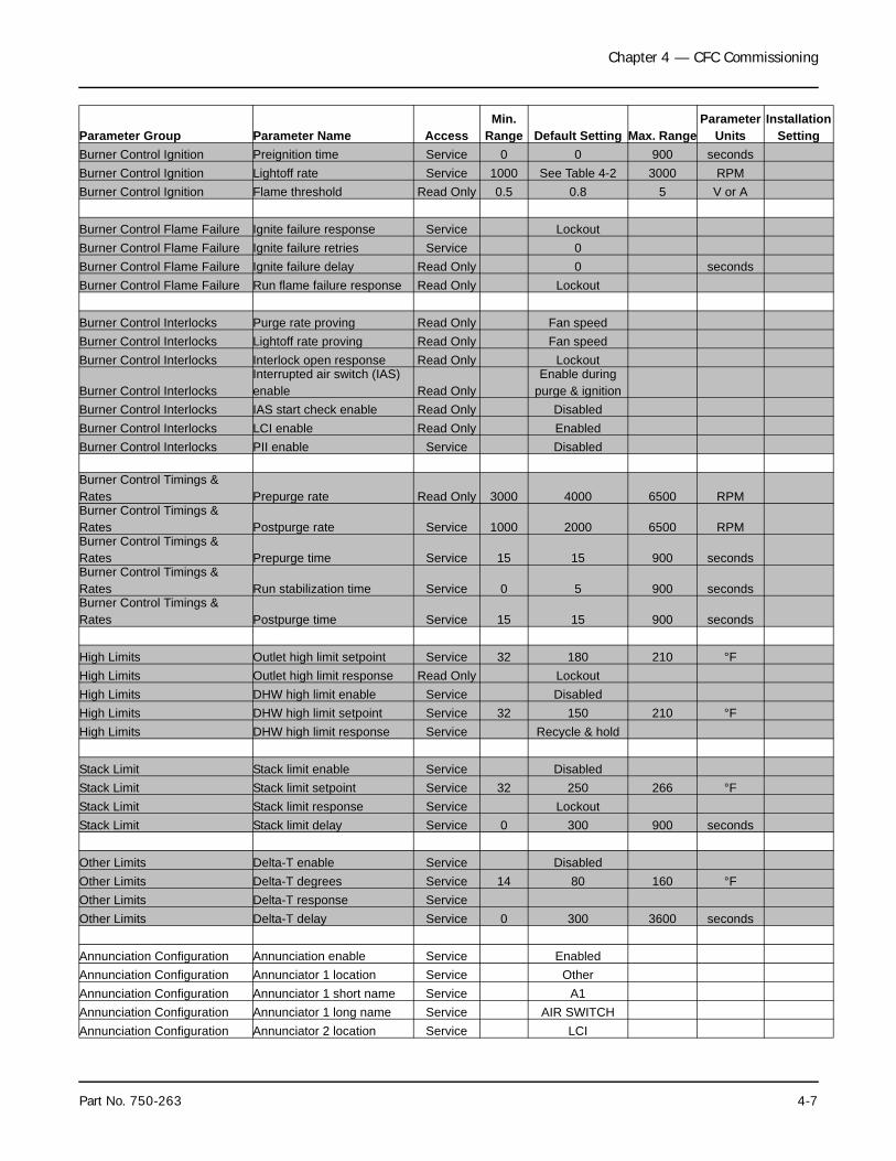
Chapter 4 — CFC Commissioning
Parameter Group Parameter Name AccessMin. Range Default Setting Max. Range
Parameter Units
InstallationSetting
Burner Control Ignition Preignition time Service 0 0 900 secondsBurner Control Ignition Lightoff rate Service 1000 See Table 4-2 3000 RPMBurner Control Ignition Flame threshold Read Only 0.5 0.8 5 V or A
Burner Control Flame Failure Ignite failure response Service LockoutBurner Control Flame Failure Ignite failure retries Service 0Burner Control Flame Failure Ignite failure delay Read Only 0 secondsBurner Control Flame Failure Run flame failure response Read Only Lockout
Burner Control Interlocks Purge rate proving Read Only Fan speedBurner Control Interlocks Lightoff rate proving Read Only Fan speedBurner Control Interlocks Interlock open response Read Only Lockout
Burner Control InterlocksInterrupted air switch (IAS) enable Read Only
Enable during purge & ignition
Burner Control Interlocks IAS start check enable Read Only DisabledBurner Control Interlocks LCI enable Read Only EnabledBurner Control Interlocks PII enable Service Disabled
Burner Control Timings & Rates Prepurge rate Read Only 3000 4000 6500 RPMBurner Control Timings & Rates Postpurge rate Service 1000 2000 6500 RPMBurner Control Timings & Rates Prepurge time Service 15 15 900 secondsBurner Control Timings & Rates Run stabilization time Service 0 5 900 secondsBurner Control Timings & Rates Postpurge time Service 15 15 900 seconds
High Limits Outlet high limit setpoint Service 32 180 210 °FHigh Limits Outlet high limit response Read Only LockoutHigh Limits DHW high limit enable Service DisabledHigh Limits DHW high limit setpoint Service 32 150 210 °FHigh Limits DHW high limit response Service Recycle & hold
Stack Limit Stack limit enable Service DisabledStack Limit Stack limit setpoint Service 32 250 266 °FStack Limit Stack limit response Service LockoutStack Limit Stack limit delay Service 0 300 900 seconds
Other Limits Delta-T enable Service DisabledOther Limits Delta-T degrees Service 14 80 160 °FOther Limits Delta-T response ServiceOther Limits Delta-T delay Service 0 300 3600 seconds
Annunciation Configuration Annunciation enable Service EnabledAnnunciation Configuration Annunciator 1 location Service OtherAnnunciation Configuration Annunciator 1 short name Service A1Annunciation Configuration Annunciator 1 long name Service AIR SWITCHAnnunciation Configuration Annunciator 2 location Service LCI
Part No. 750-263 4-7

Chapter 4 — CFC Commissioning
Parameter Group Parameter Name AccessMin. Range Default Setting Max. Range
Parameter Units
InstallationSetting
Annunciation Configuration Annunciator 2 short name Service A2Annunciation Configuration Annunciator 2 long name Service LOW WATERAnnunciation Configuration Annunciator 3 location Service UnusedAnnunciation Configuration Annunciator 3 short name Service A3
Annunciation Configuration Annunciator 3 long name ServiceAUXILIARY LOW
WATERAnnunciation Configuration Annunciator 4 location Service ILKAnnunciation Configuration Annunciator 4 short name Service A4
Annunciation Configuration Annunciator 4 long name ServiceHIGH AIR
PRESSUREAnnunciation Configuration Annunciator 5 location Service ILKAnnunciation Configuration Annunciator 5 short name Service A5
Annunciation Configuration Annunciator 5 long name ServiceHIGH GAS
PRESSUREAnnunciation Configuration Annunciator 6 location Service ILKAnnunciation Configuration Annunciator 6 short name Service A6
Annunciation Configuration Annunciator 6 long name ServiceLOW GAS
PRESSUREAnnunciation Configuration Annunciator 7 location Service UnusedAnnunciation Configuration Annunciator 7 short name Service A7Annunciation Configuration Annunciator 7 long name Service Annunciator7Annunciation Configuration Annunciator 8 location Service UnusedAnnunciation Configuration Annunciator 8 short name Service A8Annunciation Configuration Annunciator 8 long name Service Annunciator8Annunciation Configuration PII short name Service PIIAnnunciation Configuration PII long name Service Pre-Ignition ILKAnnunciation Configuration LCI short name Service LCI
Annunciation Configuration LCI long name ServiceLoad Control
InputAnnunciation Configuration ILK short name Service ILKAnnunciation Configuration ILK long name Service Interlock
Central Heat Configuration CH enable User Enabled
Central Heat Configuration CH demand source ServiceSensor & Stat
terminalCentral Heat Configuration CH sensor Service Outlet sensorCentral Heat Configuration CH setpoint User 32 150 194 °FCentral Heat Configuration CH TOD setpoint Service 32 120 194 °FCentral Heat Configuration CH on hysteresis Service 2 5 60 °FCentral Heat Configuration CH off hysteresis Service 2 15 60 °FCentral Heat Configuration CH outdoor reset enable Service DisabledCentral Heat Configuration CH P gain Service 0 50 400Central Heat Configuration CH I gain Service 0 50 400Central Heat Configuration CH D gain Service 0 0 400Central Heat Configuration CH hysteresis step time Service 0 60 900 seconds
Outdoor Reset ConfigurationCH ODR max. outdoor temperature Service -40 80 140 °F
Outdoor Reset ConfigurationCH ODR min. outdoor temperature Service -40 0 140 °F
Outdoor Reset ConfigurationCH ODR min. water temperature Service 32 50 180 °F
4-8 Part No. 750-263

Chapter 4 — CFC Commissioning
Parameter Group Parameter Name AccessMin. Range Default Setting Max. Range
Parameter Units
InstallationSetting
Domestic HW Configuration DHW enable User Disabled
Domestic HW Configuration DHW demand source ServiceOutlet sensor &
DHW switch
Domestic HW ConfigurationDHW priority has priority over CH Service Yes
Domestic HW ConfigurationDHW priority has priority over LL Service No
Domestic HW Configuration DHW priority time Service 0 1800 14400 secondsDomestic HW Configuration DHW setpoint User 32 140 180 °FDomestic HW Configuration DHW TOD setpoint Service 32 120 180 °FDomestic HW Configuration DHW on hysteresis Service 2 5 80 °FDomestic HW Configuration DHW off hysteresis Service 2 15 80 °FDomestic HW Configuration DHW P gain Service 0 50 400Domestic HW Configuration DHW I gain Service 0 50 400Domestic HW Configuration DHW D gain Service 0 0 400Domestic HW Configuration DHW hysteresis step time Service 0 60 900 secondsPump Configuration CH pump output Service Pump CPump Configuration CH pump control Service AutoPump Configuration CH pump overrun time Service 0 60 28800 seconds
Pump ConfigurationCH pump frost protection overrun time Service 0 3600 28800 seconds
Pump Configuration DHW pump output Service No assignmentPump Configuration DHW pump control Service AutoPump Configuration DHW pump overrun time Service 0 60 28800 seconds
Pump ConfigurationDHW pump frost protection overrun time Service 0 3600 28800 seconds
Pump Configuration Boiler pump output Service No assignmentPump Configuration Boiler pump control Service AutoPump Configuration Boiler pump overrun time Service 0 60 28800 secondsPump Configuration Auxiliary pump output Service Pump APump Configuration Auxiliary pump control Service AutoPump Configuration Auxiliary pump on when Service CH pump onPump Configuration System pump output Service Pump BPump Configuration System pump control Service AutoPump Configuration System pump overrun time Service 0 60 28800 secondsPump Configuration Pump exercise interval Service 0 0 28800 secondsPump Configuration Pump exercise time Service 0 0 28800 seconds
Frost Protection Configuration CH frost protection enable Service DisabledFrost Protection Configuration DHW frost protection enable Service Disabled
Frost Protection ConfigurationOutdoor frost protection setpoint Service -40 32 120 °F
Anti-condensation Configuration CH anti-condensation enable Service DisabledAnti-condensation Configuration
CH anti-condensation setpoint Service 32 140 194 °F
Anti-condensation Configuration
CH anti-condensation pump force off Service Disabled
Anti-condensation Configuration
DHW anti-condensation enable Service Disabled
Part No. 750-263 4-9

Chapter 4 — CFC Commissioning
*Access Levels:Read Only = parameter not user-configurableService = password required (9220)User = no password required
Parameter Group Parameter Name AccessMin.
Range Default Setting Max. RangeParameter
UnitsInstallation
SettingAnti-condensation Configuration
DHW anti-condensation setpoint Service 32 140 194 °F
Anti-condensation Configuration
DHW anti-condensation pump force off Service Disabled
Anti-condensation Configuration
Anti-condensation > Outlet limit Service No
Anti-condensation Configuration Anti-condensation > Delta-T Service NoAnti-condensation Configuration
Anti-condensation > Stack limit Service No
Anti-condensation Configuration
Anti-condensation > Slow start Service Yes
Anti-condensation Configuration
Anti-condensation > Forced rate Service Yes
Lead Lag Configuration Lead Lag slave enable Service DisabledLead Lag Configuration Fan rate during off cycle Service 900 1500 6500 RPM
** Shaded parameters are Safety Parameters and require Verification and manual reset of the control prior to operation. Please refer to Section A, "Changing parameter settings".
4-10 Part No. 750-263

Chapter 4 — CFC Commissioning
1. Changing Parameter SettingsTo access the CB Falcon configuration menu, press <Configure> onthe Status page.
Some parameters require a password entry before allowingchanges. The <Login> button will appear when any password-protected parameter is displayed on the screen.
Press <Login> to display the alphanumeric keyboard. Enterpassword and press <OK>
Change parameter settings by selecting the parameter on the page.A dialog box appears with controls allowing the user to change theselected value. Press <Clear> to clear the current value. Enter thenew value and press <OK> (press <Cancel> to leave theparameter unchanged).
Safety Parameters
For safety configuration parameters an additional verification step isrequired to confirm the changes.
1. When a safety parameter is changed, the Safety Parameter Verification page will appear. Press <Begin> to continue.
2. The affected parameter group will be displayed, showing current parameter values and a prompt, “Are these parameters set to proper values?”. Press <Yes> to continue.
3. The screen will indicate RESET DEVICE NOW. Open the control panel and press the RESET button on the CB Falcon controller (press and hold for 3 seconds).
RESET must be pressed within 30 seconds to save changes.
Note: When changing multiple safety parameters, the verification steps do not need to be completed immediately.See Appendix for complete instructions on using the CB Falcon Display/Interface.
Figure 4-6 Configuration Menu
Figure 4-7 Parameter change dialog
Part No. 750-263 4-11

Chapter 4 — CFC Commissioning
G.BURNER SEQUENCEIn addition to providing modulation control, the CB Falcon isresponsible for flame supervision and burner sequencing.
The CFC boiler uses direct spark ignition (no gas pilot) to light themain flame. Flame sensing is accomplished with a flame rod, orionization electrode.
Basic burner sequencing (Central Heat):
1. Heat request detected (Setpoint minus On Hysteresis); LCI demand detected (terminal J6 3).
2. The CH pump is switched on.3. After a system Safe Start Check, the Blower (fan) is switched on after a
dynamic ILK switch test (if enabled).4. After the ILK input is energized, 10 sec. allowed for IAS input
(combustion air proving) to energize, and purge rate proving fan RPM is achieved - prepurge time is started.
5. When 30 sec. purge time is complete, the purge fan RPM is changed to the lightoff speed.
6. As soon as the fan-rpm is equal to the light-off RPM , the Trial for Ignition (4 sec.) or Pre-Ignition Time is started (depending on configuration).
1. Press <Begin>
2. Press <Yes>
3. Reset CB Falcon
Confirming Safety Parameter changes
4-12 Part No. 750-263

Chapter 4 — CFC Commissioning
7. Pre-Ignition Time will energize the ignitor and check for flame.8. Trial for Ignition.9. The ignition and the gas valve are switched on.10.The ignition is turned off at the end of the direct burner ignition period. 11.The fan is kept at the lightoff rate during the stabilization timer, if any.12.Before the release to modulation, the fan is switched to minimum RPM
for the CH Forced Rate and Slow Start Enable, if the water is colder than the threshold.
13.Release to modulation.14.At the end of the CH-heat request the burner is switched off and the fan
stays on until post purge is complete.15.A new CH-request is blocked for the forced off time set by the Anti Short
Cycle (if enabled).16.The pump stays on during the pump overrun time (if enabled).17.At the end of the pump overrun time the pump will be switched off.
H.FAN SPEED SETTINGSBecause the input is determined by the fan speed, fan speedsettings may have to be modified for the particular application, forhigh altitudes, or when using direct vent combustion. Table 4-2provides the default fan speed settings in typical applications for thevarious boiler sizes. To allow safe modulation through the firingrange, these parameters should be initially set to the recommendedspeeds. Please contact your author ized Cleaver-Brooksrepresentative for proper settings in high altitude and direct ventcombustion applications.
I. INITIAL START-UP PROCEDURE1. Gas Train and PipingThe ClearFire burner is equipped with a combination servo-regulated gas valve and venturi mixing unit. The gas valve consistsof a single body with dual solenoid shut off valves, filter screen, anda built-in constant pressure gas/air servo controller. The blowerspeed is controlled by the CB Falcon with airflow directlyproportional to the speed of the fan. The airflow creates a drop inpressure due to the venturi effect. The modulating controller of thevalve actuator senses air pressure change and accordingly brings
Table 4-2 Fan Speed SettingsSetting CFC-500 CFC-750 CFC-1000 CFC-1500 CFC-1800 CFC-2500Max. Speed (RPM) CH 5500 5300 5300 5300 4600 5000Max. Speed (RPM) DHW 5500 5300 5300 5300 4600 5000Min. Speed (RPM) 1300 1200 1100 1100 900 1100Ignition Fan Speed (Lightoff Rate) 2200 2000 1800 1800 1500 1800
! WarningBefore initial startup, check for block-ages in the flue venting or vent termi-nations. Inspect the burner and furnace for any contamination or blockages.
Part No. 750-263 4-13

Chapter 4 — CFC Commissioning
about a change in the gas flow proportional to the air pressure. Thegas follows the airflow in a set ratio, so that fuel always matchesthe air as the burner firing rate increases or decreases.
1. Check the gas delivery system to be sure it is properly piped andwired.
2. Review available gas pressure to assure it is compatible with themain gas regulators upstream of the Model CFC gas train. Note:The maximum rated inlet pressure to the CFC gas train is 1/2psig (14.0" WC). An upstream regulator and overpressureprotection are required if building supply gas pressure isgreater than 1 psig.
3. To bleed air from the supply pipe, open the manual gas shut offvalve upstream of the burner gas train and bleed air from thepiping by loosening the union in the upstream piping.
4. The burner and its gas connection must be leak tested beforeplacing the boiler into operation.
5. Gas Pressure Regulator - Using the adjusting screw on the maingas regulator, adjust the inlet pressure to the recommendedlevels in Table 4-3.
2. Power-Up1. Ensure blower motor is properly wired for the available power
supply.
2. Verify the voltage (control voltage is 115V-1Ph.-60Hz) to ensureit is within specifications.
3. Operation Check: Gas Valve, Gas Pressure Switches, and Combustion Air Proving Switch
Before initial firing of the burner, the gas valve, Low Gas PressureSwitch (LGPS), High Gas Pressure Switch (HGPS), and CombustionAir Proving Switch (CAPS) should be checked for proper operation.
Table 4-3 Model CFC Gas Pressure Requirements
BoilerInput
Pressure Required atgas train connection
Max.pressure
Low Fire HighFire
500-1000
7" w.c. 5" w.c.
14” w.c.1500 10" w.c. 7" w.c.1800 7" w.c. 5" w.c.2500 9.5" w.c. 8" w.c.
Figure 4-8 Premix Burner Technology - Full Modulation
4-14 Part No. 750-263

Chapter 4 — CFC Commissioning
• Before proceeding, review Section 4.3 - Control Setpoints for initial LGPS, HGPS, and CAPS settings.
Note: Close the downstream manual gas shut-off valve beforechecking pressure switches and CAPS.
While performing the following safety checks, use the CB FalconAnnunciation screen to monitor the status of the circuits involved.Press <Annunciation> on the Operation page to access this screen.
LGPS
1. To check the Low Gas Pressure Switch, first close the upstreammanual shutoff valve (both manual shutoff valves should now beclosed).
2. Start the burner and wait 10 seconds during purge for CAPS tobe made.
3. Turn the LGPS setting to maximum.4. Open the test cock to bleed the gas line.5. The controller should lock out. The screen will indicate Lockout
67 ILK OFF.6. Reset the controller and change the LGPS setting back to
minimum to proceed.
CAPS
1. Initiate burner sequence. 2. During purge cycle, set Combustion Air Proving Switch to its
maximum setting. 3. The CB Falcon should lock out on an airflow failure. The display
will show Lockout 65 Interrupted Airflow Switch OFF.
Note: If the CAPS fails to open even when set to maximum, test by disconnecting the low-pressure line to the switch and initiating burner sequence. The switch should now break during the purge cycle. Reconnect low-pressure side after a suc-cessful CAPS check.
4. Following a successful CAPS check, dial the CAPS back to its minimum setting and reset the CB Falcon.
Figure 4-9 Annunciation Screen
CAPS low pressure connection
Part No. 750-263 4-15

Chapter 4 — CFC Commissioning
HGPS and GAS VALVE
1. Open the upstream manual shutoff valve and wait a few moments for gas pressure to rise.
2. Lower the switch setting to minimum.3. Initiate burner sequence. During the main flame establishing
period, verify gas valve LEDs energize, indicating both safety shutoff valves open.
4. The CB Falcon should lock out on an interlock failure (Lockout 67).
5. Reset CB Falcon.6. Open the downstream manual shutoff valve to clear the lockout
condition.7. Dial the HGPS back to its maximum setting and reset.
IGNITION FAILURE CHECK
7. A test of the flame rod circuit can also be performed at this time.Disconnect the flame rod cable and attempt to start the burner.The CB Falcon should lock out, indicating Lockout 109 IgnitionFailure.
8. Replace flame rod electrode and grounding tab.
After verifying proper operation of LGPS, HGPS, CAPS, and GasValve, re-open the downstream manual shut-off valve.
4. LOW WATER CUTOFF Check1. Hold down the LOW WATER RESET-TEST switch for 3 seconds.2. Check Annunciation screen. The LCI section (Limit Control Input
circuit) should show A2 Water level: OFF (Figure 4-8).3. Press RESET-TEST switch once to reset.
5. Low and High Fire Adjustments
All CFC boilers are factory tested firing natural gas at an altitude of1000 ft ASL. Operating under different conditions may require re-adjustment of the gas valve.
Adjustments are made using a TORX® T40 (low fire adjustment)and 3 mm hex wrench (main gas choke). The adjustment screwsshould initially be set to half way through each setting’s range. Thelow fire adjustment screw is accessed by removing the slotted capon the gas regulator using a blade screwdriver (see Figure 4-11).The high fire adjustment screw is accessed by removing the blueplastic cap from the valve cover (see Figure 4-12).
Turn the adjustment screw completely clockwise, counting the turnsuntil the screw will no longer turn. Then, turn the adjustment screwcounterclockwise half the number of turns counted when turningclockwise.
Figure 4-10 Low Water Cutoff test
Figure 4-11 Regulating Adjusting Screw - Low Fire
Offset
4-16 Part No. 750-263
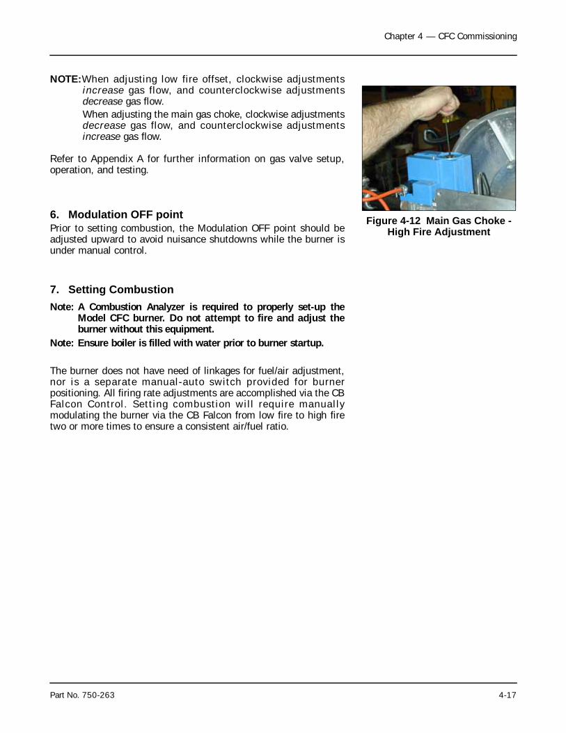
Chapter 4 — CFC Commissioning
NOTE:When adjusting low fire offset, clockwise adjustmentsincrease gas flow, and counterclockwise adjustmentsdecrease gas flow.When adjusting the main gas choke, clockwise adjustmentsdecrease gas flow, and counterclockwise adjustmentsincrease gas flow.
Refer to Appendix A for further information on gas valve setup,operation, and testing.
6. Modulation OFF pointPrior to setting combustion, the Modulation OFF point should beadjusted upward to avoid nuisance shutdowns while the burner isunder manual control.
7. Setting CombustionNote: A Combustion Analyzer is required to properly set-up the
Model CFC burner. Do not attempt to fire and adjust theburner without this equipment.
Note: Ensure boiler is filled with water prior to burner startup.
The burner does not have need of linkages for fuel/air adjustment,nor is a separate manual-auto switch provided for burnerpositioning. All firing rate adjustments are accomplished via the CBFalcon Control. Setting combustion will require manuallymodulating the burner via the CB Falcon from low fire to high firetwo or more times to ensure a consistent air/fuel ratio.
Figure 4-12 Main Gas Choke - High Fire Adjustment
Part No. 750-263 4-17

Chapter 4 — CFC Commissioning
To set combustion:
1. Check inlet gas pressure and reset low gas pressure switch.
2. At Operation screen set firing rate to low fire. Review burnersequence before proceeding.
3. Turn LOCAL/REMOTE switch to LOCAL.
4. Initiate burner firing sequence. The burner switch is accessedvia the CB Falcon Operation page (Figure 4-11). If the burnerdoes not ignite, adjust choke counterclockwise slightly until youcan see a slight yellow flame at the burner during ignition.Clockwise adjustments to the low-fire offset screw may also betried. Check that gas pressure to gas valve inlet is sufficient tofire burner (see Table 4-3 for gas pressure requirements).
5. After burner lights, maintain in low fire position. At low fire,using main choke on gas valve and a combustion analyzer setO2 level within 3-8% O2.
1. On the CB Falcon Operation screen, press the Firing rate display in the Modulation section.
2. A numeric keypad will appear, showing the current firing rate.
3. Press <Clear> to clear the current value.4. Enter the desired RPM setting using the numeric keypad (refer to Table 4-2, Fan Speed Settings).5. Press <OK>. The display will return to the Opera-tion screen and the burner will modulate to the cho-sen firing rate.
Manual Modulation - use the procedure below to change the burner firing rate manually.
Figure 4-13 Operation screen
4-18 Part No. 750-263

Chapter 4 — CFC Commissioning
6. Manually modulate the burner to high fire. Adjust the gas chokeif necessary to obtain desired O2% (5% - 6%).
7. Modulate to low fire and fine tune offset screw to obtain desiredO2% (5% - 6%).
Verify adjustments by modulating back and forth between low andhigh fire.
While setting combustion observe gas pressure at low fire and athigh fire. Ensure pressure is within limits shown in Table 4-3.
8. High Air Pressure Switch settingsThe High Air Pressure witch (HAPS) is used to safely shut down theboiler in case of a blocked flue or blocked condensate condition.
The HAPS switch setting for each model CFC can be found below:
Table 4-4 HAPS Settings
The HAPS has a manual reset, similar to the High/Low gas pressureswitches.
Note: In the event of a HAPS lockout, investigate possible causesbefore attempting to restart boiler.
9. Limit Controls CheckThe Modulation Off (operating limit) and High Limit functions canbe tested while the boiler is operating by adjusting the respectivesetting downward and allowing the boiler outlet temperature to rise.The Modulation Off point is the sum of the Modulating setpoint andthe Hysteresis Off value. The Modulation On point is the setpointminus the Hysteresis On value.
When the boiler ’s outlet temperature exceeds either of thesesettings, the boiler will shut down. When the operating limit isexceeded, the boiler will automatically recycle upon the outlettemperature dropping below the on point. When the High Limit isexceeded, a lockout should result requiring a manual reset of thecontrol after the temperature has dropped below the high limitsetting.
Before testing the High Limit, temporarily set the Modulation OFFpoint higher than the High Limit setting.
Restore Modulation OFF and High Limit to operational settings aftertesting.
Specific settings are determined by application. Maximum HighLimit for Model CFC is 210 deg F.
Model SettingCFC-500 3.5” W.C.CFC-750 3.5” W.C.CFC-1000 3.5” W.C.CFC-1500 4.5” W.C.CFC-1800 4.5” W.C.CFC-2500 5.25” W.C.
Part No. 750-263 4-19

Chapter 4 — CFC Commissioning
The High Limit setting is considered a safety parameter. Anychanges made will require a password login and reset of the CBFalcon.
J. POST START-UP CHECKOUT PROCEDURE1. Ensure proper air venting to expansion tank.
2. Set high gas pressure switch to 50% higher than operating gaspressure at low fire. Set low gas pressure switch to 50% lowerthan operating gas pressure at low fire.
3. Check the draft on the outlet stack on each boiler, compare toacceptable limits (-.25 to +.25“ W.C.) and record in start upform. Operating outside of acceptable limits could result in lightoff and flame failure problems.
4. Switch to automatic operation and monitor flue gas to ensureconsistent excess air.
5. Reassemble all panels and covers that were removed andreplace any plugs that were removed to check gas pressure.
6. Verify HAPS switch operation by simulating a blocked fluecondition.
7. Verify gas pressures remain within limits shown in Table 4-3.
8. Provide instructions to owner and operators on operation, safetyand maintenance of the equipment.
9. Provide instructions to owner and operators on proper watertreatment guidelines and procedures.
4-20 Part No. 750-263

Milwaukee, Wisconsin
www.cleaver-brooks.com
Chapter 5Service and Maintenance
Cleaning Procedure / Disassembly ........................................... 5-2Condensate Neutralization ...................................................... 5-3Assembly ............................................................................. 5-3Ignition Electrode and Flame Rod ............................................ 5-4Troubleshooting ..................................................................... 5-4
! Caution Label all wires prior to disconnection when servicing controls. Wiring errors can cause improper and dangerous operation.Failure to do so may result in equipment failure.
! CautionVerify proper operation after servicing. Failure to do so may result in equipment

Chapter 5 — Service and Maintenance
On an annual basis the boiler vessel and burner combustion systemmust be checked and cleaned. This work is to be carried out by anauthorized Cleaver-Brooks Service Technician.
A. CLEANING PROCEDURE / DISASSEMBLY1. Close off the gas supply to the boiler and disconnect electrical
power at the primary switch box.2. Remove the front casing panel and fold the integral step down
(see Figure 5-1).3. Remove the top casing of the boiler.4. Disconnect the gas piping to the burner head.
5. Disconnect the electrical connections to the blower assembly.6. Remove air combustion piping if supplied.7. Unscrew the four- (4) hold down nuts securing the burner door
to the pressure vessel.8. The burner door, burner head, blower motor and assembly will
lift on the provided gas struts (see Figure 5-3).9. The blower motor and gas valve assembly assembly can be
removed from the boiler.10. The burner head can be separated from the head assembly by
removing 4 bolts and washers.Check the burner head for any damage, burn marks or perforations.If damage is determined replace the damaged parts. If the canisteris in good condition clean out any dirt and contaminates with avacuum cleaner inside and out alternating with compressed air todislodge any debris of combustion.
1. With the burner head and blower removed the combustion chamber can be accessed for all service requirements.
2. Check ignition and ionization electrodes for deposits and propergap. Clean or replace as needed.
3. Inspect the pressure vessel and combustion chamber area forany damage or contamination (see Figure 5-4). If dirt orcontaminates are found it is recommended that the tubes bewashed with a high-pressure power washer.
Figure 5-1 Service Step
Figure 5-2 Burner Head (in place)
A. Gas Assist lift cylinders (2)B. Burner head hold down nuts
A B
BB
(BOTH SIDES)
Figure 5-3 Burner Door! Caution
Label all wires prior to disconnection when servicing controls. Wiring errors can cause improper and dangerous operation. Verify proper operation after servicing.
5-2 Part No. 750-263

Chapter 5 — Service and Maintenance
B.CONDENSATE NEUTRALIZATION Important note concerning the neutralization system:
The neutralization granulate NEUTRALAT is supplied in 6.5 lb.bags. The bags have 2 wrappers. The actual granulate is containedin a mesh type inner wrapper which in turn is enclosed in a sealedouter wrapper; do not remove the mesh wrapper.
After removing the outer wrapper, the fine dust formed duringtransport should be shaken out as it can impair the effectiveness.The granulate is placed in the granulate chamber around thevertical round inlet tube on the filter mat (not in the containerbehind it, which is for the neutralized condensate).
Once a year - or after consumption (dissolving) of the granulate - theneutralization system should be thoroughly cleaned, i.e. rinsed withwater. For this the neutralization tank can be easily removed andreplaced after taking off the removable front and disconnecting thecondensate connector.
The tank is located between 2 rails with a stop at the rear. As it isharmless, the residual neutralization granulate can be disposed ofwith the domestic waste. For the CFC 750-1000, the granulatetank requires three (3) 6.5 lb. bags of NEUTRALAT. The CFC 1500-1800 requires four (4) 6.5 lb. bags of NEUTRALAT.
Applications where multiple boilers are used will require morefrequent maintenance and replacement of the neutralization media
Important!The granulate tank is to be filled with NEUTRALAT neutralisation granulate as described above before the first commissioning
C. ASSEMBLY1. Assembly is the reverse of the above instructions.2. A new rope gasket should be installed on the burner door.See recommended spare parts list.
Figure 5-4 Combustion Chamber and Tube Sheet
Part No. 750-263 5-3

Chapter 5 — Service and Maintenance
D. IGNITION ELECTRODE AND FLAME RODThe ignition and ionization electrodes should be checked on anannual basis. If damaged it should be replaced as shown in Figure5-5 with the electrode turned towards the burner mantle after it isinserted into the burner head.
1/8” gap between ionization electrode and the surface of the burnercanister.
1/8” gap between ignitor electrode and ground electrode.
E. TROUBLESHOOTING
Lockout Conditions
1. Observe lockout code and description - refer to CB Falcon appendix if necessary.
2. After determining lockout condition, investigate possible causes.3. When cause is diagnosed, remedy condition.4. Reset control. Boiler should be able to start normally.5. If lockout recurs, further investigation is required. Repeat steps 1
through 4 as needed. If necessary, contact your CB service representa-tive for technical support.
EXAMPLE: Lockout 79 Outlet Temperature High Limit
1. Before resetting control to clear lockout, check for sufficient water flow through boiler. Possible sources of insufficient flow include closed water valves, insufficient pump speed, air trapped in boiler (inadequate air venting), or modulation set point and off point close to outlet high limit setting.
The CB Falcon system display/interface provides extensive boiler diagnostic data at the time of lockout that can help in determining the source of a problem. This information is accessed through the Lockout History.
2. Remedy condition that caused lockout to occur.3. Reset control by pressing <Clear Lockout> from the Lockout History
screen.
Light-off Problems
The distance between the flame rod and the burner (mantle) shouldbe 1/8” (see Figure 5-6). The dimensions on both the boosterignitors and the flame rod are not easily adjustable - bending therods can cause damage to the insulation material. Also a bentelectrode will return to its original shape when heated. If anelectrode or flame rod is out of specification, replacement isgenerally required. Clean or replace as necessary.
Figure 5-5 Electrode Setup
5-4 Part No. 750-263

Chapter 5 — Service and Maintenance
Electrode spacing for the booster ignitor should be 1/8”.
The distance of the nearest booster ignitor electrode to the mantleis approximately 1/2” (See Figure 5-7).
Figure 5-6 Flame Rod and Ignitors
1/8”
Flame Rod
Booster Ignitor Bottom of
Burner Canister
Figure 5-7 Ignitor Electrodes
1/8”
1/2”
Part No. 750-263 5-5


Chapter 6Parts
Recommended Spare Parts List Model CFC ................................. 6-1Boiler mechanical assembly ...................................................... 6-2Boiler mechanical assembly parts list ......................................... 6-3Connection Sizes ...................................................................... 6-3Gas train ................................................................................. 6-4Gas train parts list .................................................................... 6-4MSOV Kit ................................................................................ 6-4Electrical Assemblies ................................................................ 6-5Electrical Assemblies Parts List .................................................. 6-6Control Panel ........................................................................... 6-6Blower Fuse ............................................................................. 6-6CFC Optional Parts List ............................................................. 6-7Vent Connections ..................................................................... 6-7
Table 6-1. Recommended Spare Parts List Model CFCBoiler Size
Item 500 750 1000 1500 1800 2500Ionization Electrodes 380-1062 380-1062 380-1060 380-1060 380-1060 380-1060Dual Electrode, Sparking 380-1061 380-1061 380-1061 380-1061 380-1061 380-1061Dual Electrode Gasket 380-1032 380-1032 380-1032 380-1032 380-1032 380-1032Burner Canister 380-1045 380-1045 380-1029 380-1030 380-1030 380-1074Water Side Gaskets 853-350Manual 750-263 750-263 750-263 750-263 750-263 750-263Falcon Controller, Hydronic 833-3639 833-3639 833-3639 833-3639 833-3639 833-3639Power Supply, 12VDC 832-2410 832-2410 832-2410 832-2410 832-2410 832-2410Fuses (5A), Control Circuit 832-1811 832-1811 832-1811 832-1811 832-1811 832-1811Gasket,Burner Canister (2) 380-1053 380-1053 380-1033 380-1034 380-1034 380-1034Gasket, Adapter to Blower 380-1037 380-1037 380-1037 380-1076 380-1038 380-1038Cable, Blower Signal 832-2434 832-2434 832-2434 832-2434 832-2434 832-2434Ionization Cable (Flame Rod) 826-157 826-157 826-157 826-157 826-157 826-157Ignition Cable (2) 826-156 826-156 826-156 826-156 826-156 826-156Blower Power Cord 832-2101 832-2101 832-2101 832-2101 832-2101 832-2101Blower Fuse 15A 832-1812 832-1812 832-1812 832-2241 832-2241 832-2241Burner Sight Glass 851-26 851-26 851-26 851-26 851-26 851-26Retainer, Sight Glass 65-879 65-879 65-879 65-879 65-879 65-879Gasket, Sight Glass (2) 853-213 853-213 853-213 853-213 853-213 853-213
Milwaukee, Wisconsin
www.cleaver-brooks.com

Chapter 6 — Parts
Figure 6-1. Boiler mechanical assembly
c
A
D
6-2 Part No. 750-263

Chapter 6 — Parts
Table 6-2. Boiler mechanical assembly parts list
Table 6-3. Connection Sizes
2500500 750 1000 1500 1800
BOILER SIZE
500 750 1000 1500 1800 2500BOILER SIZE
Part No. 750-263 6-3

Chapter 6 — Parts
Figure 6-2. Gas train
Table 6-4. Gas train parts list
Table 6-5. MSOV KitBOILER SIZE 500 750 1000 1500 1800 2500
1’’ NPT KIT# 380-01046 1.25’’ NPT KIT# 380-1047
BUTTERBALL VALVE 941-01944 941-01944 941-01944 941-01945 941-01945 941-01945
NIPPLE, CLOSED 857-00673 857-00673 857-00673 857-00709 857-00709 857-00709
ADAPTER, GAS VALVE 800-00092 800-00092 800-00092 800-00093 800-00093 800-00093
O-RING W/HARDWARE
GASKET W/HARDWARE 800-98 800-98 800-98 800-99 800-99 800-99
BOILER SIZE
6-4 Part No. 750-263

Chapter 6 — Parts
Figure 6-2. Electrical Assemblies
INCOMING POWERANDCUSTOMER CONNECTIONTERMINALS
Part No. 750-263 6-5

Chapter 6 — Parts
Table 6-6. Electrical Assemblies Parts List
Table 6-7. Control Panel
Table 6-8. Blower Fuse
ITEM QTY PART NO. DESCRIPTION1 1 See Table 6-6 CONTROL PANEL2 1 833 03577 DISPLAY, SYSTEM3 1 833-03725 DISPLAY, LOCAL5 1 832 02410 POWER SUPPLY (INCLUDED W/SYSTEM DISPLAY)6 1 833 03639 FALCON CONTROLLER7 1 832 00235 TRANSFORMER8 1 832 02451 IGNITION TRANSFORMER9 1 833 03547 CONTROLLER, LWCO10 2 848 01166 FUSE BLOCK, SINGLE POLE11 1 See Table 6-7 FUSE, 15 AMP, LPCC TIME DELAY, BLOWER FUSE12 1 832 01811 FUSE, 5 AMP, CONTROL CIRCUIT13 2 836 01147 SWITCH, SELECTOR, 2 POSITION14 2 836 01136 CONTACT BLOCK15 1 879 00995 NAME PLATE, BOILER OFF-ON16 1 879 00995 NAME PLATE LOCAL/REMOTE17 832 02326 TERMINAL BLOCK18 8 832 02328 TERMINAL, GROUNDING19 3 832 02248 TERMINAL END RETAINING ANCHOR20 832 02327 TERMINAL LABEL CLIP21 3 832 02249 JUMPER, 2 POLE22 1 848 01321 FUSE BLOCK23 1 832 01211 FUSE, 1 AMP24 2 832 01951 DIN RAIL25 2 826B00156 IGNITION CABLE26 1 826B00157 FLAME ROD CABLE27 1 832B02434 BLOWER SIGNAL CABLE28 1 826B00160 CABLE HARNESS29 832B02452 BLOWER POWER CORD
Boiler Size500 750 1000 1500 1800 2500
ITEM 1 - CONTROL PANEL 283-03537 283-03537 283-03536 283-03535 283-03542 283-03492
Boiler Size500 750 1000 1500 1800 2500
ITEM 11 - BLOWER FUSE 832-01812 832-01812 832-01812 832-02241 832-02241 832-02241
6-6 Part No. 750-263

Chapter 6 — Parts
Table 6-9. CFC Optional Parts List
Table 6-10. Vent Connections
DESCRIPTION PART NO.DIRECT VENT KIT, CFC 500, 750 & 1000 880-01312DIRECT VENT KIT, CFC 1500 & 1800 880-01313DIRECT VENT KIT, CFC 2500 880-2451AIR INLET FILTER, CFC 500, 750 & 1000 843-266AIR INLET FILTER, CFC 1500, 1800, & 2500 843-267AIR FILTER CLEANING KIT 880-CONDENSATE TREATMENT SYSTEM, CFC 500, 750 & 1000 617-00187CONDENSATE TREATMENT SYSTEM, CFC 1500 & 1800 617-00187FLUE GAS CONDENSATE NEUTRALIZING MEDIA 947-00007OPTIONAL SAFETY VALVE SET @ 30 PSI 940-478OUTDOOR TEMP. SENSOR, INCL. EXTERNAL MOUNTING HARDWARE 817-4467ALARM HORN 817-3571STACK TEMPERATURE SENSOR 817-4403HEADER TEMPERATURE SENSOR 817-4468DHW OUTLET TEMPERATURE SENSOR 817-4403INLET TEMPERATURE SENSOR 817-4404PLUG-IN MODULE (PIM) 833-3640AUX. LOW WATER CUTOFF 817-3390ALARM HORN 817-3571BOILER AIR VENT VALVE 940-7358
Model CFCConnection Size 500 750 1000 1500 1800 2500
4” 039-1684 NA NA NA NA NA6” 039-1704 039-1704 039-1646 NA NA NA8” NA NA 039-1647 039-1645 NA NA10” NA NA 039-1705 039-1644 039-1644 NA12” NA NA NA 039-1688 039-1688 039-1688
STANDARDOPTIONAL
Part No. 750-263 6-7


APPENDIX A - CB FALCON HYDRONIC CONTROL


PRODUCT DATA
Hydronic Control
APPLICATIONThe CB Falcon is a hydronic boiler control system that provides heat control, flame supervision, circulation pump control, fan control, boiler control, and electric ignition function. It will also provide boiler status and error reporting.
Multiple boilers can be joined together to heat a system instead of a single, larger burner or boiler. Using boilers in parallel is more efficient, costs less, reduces emissions, improves load control, and is more flexible than the traditional large boiler.
FEATURESSafety and Boiler Protection• Frost Protection, Slow Start, Anti-condensate, Boiler
Delta-T, Stack Limit, Boiler Limit, DHW Limit, Outlet T-Rise Limit
Integrated Control Functions:• Primary Flame Safeguard Control• Internal or external spark generator• Analog Input using 10kohm NTC Sensor
• Outlet Limit And Temperature• DHW (Domestic Hot Water) Limit and
Temperature• Stack Temperature Limit and Temperature• Inlet Temperature• Outdoor Temperature
• Other Analog Inputs• PWM Feedback• Flame Signal from either a Flame Rod or
Ultraviolet Detector• PID Load Control
• CH (Central Heat)• DHW (Domestic Hot Water)
• Digital Inputs• Pre Ignition Interlock• LCI (Load [or Limit]Control Input)• Airflow Interlock• Annunciation (8 Programmable) (6
Programmable plus High Fire and Low Fire Switch Interlocks)
• Remote Reset• TOD (Time of Day)
CB Falcon System Consists of:CB Falcon Control Device833-3577 Touchscreen Display—required for setup and ModBus communication but not required for the system to operate once the CB Falcon is programmed.Flame Rod or UV flame detectorTemperature Sensor, NTC Type 10KΩ at 77°F (25°C) or 12KΩ at 77°F (25°C)Limit Sensor, NTC Type 10KΩ at 77°F (25°C)Local Keyboard Display ModuleFans (VFD)

CB FALCON HYDRONIC CONTROL
750-265 2
• Digital Outputs• Pump Control (3 outputs, 5 different
programmable features)• Combustion Blower• External Ignition• Pilot Valve• Main Valve• Alarm
• Analog Outputs• Modulation
• 4-20mA• 0-10 Vdc• PWM for Variable Frequency Drives
• Algorithm Prioritization• Burner Demand
• CH, DHW and Frost Protection• Firing Rate Limiting
• Anti-Condensate, Stack Limit, Boiler Delta-T, Boiler Slow Start, Outlet Limit, On and Off Hysteresis
• Two Temperature Loops of Control• CH• DHW
• High Limit Control (Meets UL 353)• Fifteen Item Fault Code History including equipment
status at time of lockout• Fifteen Item Alert Code Status including equipment
status at time of internal alerts• 24Vac Device Power• 24 or 120Vac Digital I/O models available.• Flame Signal test jacks (Vdc)• Three Status LEDs
• Power• Flame• Alarm
• Analog NTC Sensor Inputs (10kohm or 12kohm)NOTE: 12kohm sensors cannot be used for Limit
Application functions.• Flame Sensing
• Ultraviolet • Flame Rod
• Single Element (Internal spark generator and flame sense using the same element)
• Dual Element (separate elements for ignition spark and flame sense)

3 750-265
TABLE OF CONTENTSApplication ......................................................................................................................................................... 1Features ............................................................................................................................................................. 1Overview ............................................................................................................................................................ 7Installation .......................................................................................................................................................... 9Wiring ................................................................................................................................................................. 9Startup ................................................................................................................................................................ 16Parameter Control Blocks (PCB) ....................................................................................................................... 16Programming Safety Parameters ....................................................................................................................... 17Annunciator ........................................................................................................................................................ 48Fault Handling .................................................................................................................................................... 51
Lockouts and Alerts .................................................................................................................................... 51Alarms for Alerts ......................................................................................................................................... 51Sensor Signal Conditioning ........................................................................................................................ 51
Burner Control Operation ................................................................................................................................... 52Safety Shutdown of Burner Control Functions ............................................................................................ 52Standby Hold .............................................................................................................................................. 52Operational Sequence ................................................................................................................................ 52
Parameter Glossary ....................................................................................................................... 54Global Modbus .................................................................................................................................... 68Fault Code and Troubleshooting. ....................................................................................................................... 99
This Product Data sheet is intended to provide a generaloverview of the CB Falcon controller.The interaction of all of the device’s parameters makes definitively describing the actual control operation impossible.
This document is a textbook version of the parameters. The glossary beginning on page 54 provides an abbreviated parameter explanation along with a reference page for a more in-depth explanation.
The actual setup of the controller is accomplished using the 833-3577 System Operator Interface or the DSP3944 SetupTool. This document will assist in understanding the parameters being set up.
Included is a worksheet example (p. 63) of the device’s parameters and how they might be set up to provide a functioning system.
Note that this sheet (like the CB Falcon System Operator Interface) shows all parameters. The actual product may have parameters made invisible or read-only by the OEM, as they may not apply for their product.

750-265 4
FEATURES, continuedAccess codes through the display allow for different levels of setup.
— The OEM level allows for equipment to operate within guidelines that they feel necessary for safe and effi-cient operation of their equipment. The OEM makes available the parameters that the installing contractor needs for installation adjustments of the equipment.
— The installer setup information is customized by the OEM. The access code for the installer level must be obtained from the OEM.
— The User level allows for non critical adjustments for the individual piece of equipment. These would include but not limited to:• Read the error log from CB Falcon.
• Monitor the input and output variables of the controller.
• Read parameters from CB Falcon.
• CH and DHW setpoint adjustment.
Operational Features
Self TestThe Safety Processor performs Dynamic Self Checks that supervise microcomputer performance to ensure proper operation. The microcomputer tests itself and its associated hardware with comprehensive safety routines. Any malfunction will be detected by the microcomputer to cause a safety shutdown and cause the Dynamic Safety Relay to de-energize all safety-critical loads.
InitializationThe CB Falcon will start up in either the configured or unconfigured condition. In the Configured condition it is ready to operate a burner.
The CB Falcon is in the unconfigured condition whenever a safety parameter requires editing (Commissioning). The Falconremains unconfigured and will not operate a burner until all safety parameters have been reviewed and confirmed.
Safety Lockout.The R7910A can be set up to maintain a lockout condition on power interruption or to reset the lockout on a power interruption.
ResetPressing and releasing the reset button (or the remote reset input) always causes a lockout condition to be cleared, and the microcomputer that operates the burner control part of theCB Falcon to reinitialize and restart.
A safety lockout can also be reset through a writable parameter from the system display through Modbus.
Fault HandlingThe CB Falcon implements two kinds of faults: lockouts and alerts.
• Lockout causes the burner control to shutdown and requires manual or remote reset to clear the lockout.
• It always causes the alarm contact to close.• Gets logged into the 15 item lockout history.
• Alerts include every other kind of problem that does not shut the burner down. Examples of alerts are faults from non–safety functions or abnormal events that are relevant to an operator or end user.
• Alerts never require manual intervention to reset them (an alert is not a condition, it is an event).
• Whether the alarm contact closes or not is programmable by the OEM for each alert.
• Alerts are logged in the 15 item alert history and sorted in chronological order. Only one instance of each alert fault code occurs in the history, corresponding to the most recent occurrence of the alert.
Sensor Signal ConditioningThe analog sensor signal processing includes filtering to reduce the effect of noise and spurious read events.
Operating Sensors will not cause a fault condition unless the value is requested for control purposes. The Falcon will trigger an Alert if an operating sensor is malfunctioning.
Safety Sensors (Sensors used as Limits, e.g. High Temp Limit) include a comparison of redundant sensors. A safety sensor mismatch or out-of-range will result in a safety shutdown and Alarm.
Non-Volatile MemoryThe CB Falcon will store the following items in non-volatile memory:
• Factory configuration data• Parameter Control Blocks• All configuration parameters• The 15 item lockout history• Cycle and Time history
Lockout HistoryThe lockout history will contain 15 records. Each record will contain a snapshot of the following values as they existed at the time of the lockout.
• Burner Lockout/Hold identifies the cause of the lockout.• Burner State identifies the state of the burner control (e.g.
standby, purge, run).• Burner Displayed Time: mm:ss is the displayed timer
used by the Burner Control at the time of lockout (e.g. prepurge time, ignition time, etc.).
• Annunciator First-out is the first-out code for the lockout.• Burner Run Time is the elapsed time of burner operation.• Burner Cycle Count is the number of burner cycles
(based on the main valve being turned on).• All analog sensor values (Inlet, Header, Outlet, Outdoor,
DHW, and Stack)

5 750-265
Cycle and Time HistoryThe non-volatile memory will contain the following parameters and status values related to cycle counts and elapsed operation time:
• Burner Run Time: hhhhhh:mm• Burner cycle count: 0-999,999• CH cycle count: 0-999,999• DHW cycle count: 0-999,999• Boiler pump cycle count: 0-999,999• Auxiliary pump cycle count: 0-999,999• System pump cycle count: 0-999,999
These are writable parameters so they may be altered if theCB Falcon is moved, the burner is replaced or some component is replaced.
There are also two non-writable counters:
• Controller Run Time: hhhhhh:mm• Control cycle count: 0-999,999
Flame Signal ProcessingThe flame signal processing will monitor either a flame rod or a UV flame sensor. The flame signal voltage sent to the display and the test jacks will be the measured voltage without clipping and will range from 0V to 10V.
The incoming flame signals will be filtered to eliminate transient and spurious events.
The Flame failure response time (FFRT) will be 4 seconds.
Temperature SettingsAll parameters that provide a temperature will have a possible value of “None.”
This value will be a special code that is not a legal temperature. Whenever a function requires a temperature parameter it will test this parameter for a legal value, and if the “None” value is found it will respond by generating either an Alarm or a Lockout, as appropriate to the function, and either operate in an alternative manner or suspend operation, as appropriate to the function.
Modbus/EnviraCOM Event HandlingThe Modbus and EnviraCOM communication system responds to queries and can write new values to parameters.
WARNINGExplosion Hazard.Improper configuration can cause fuel buildup and explosion.Improper user operation may result in property loss, physical injury, or death.
The 833-3577 System Operator Interface used to change Safety Configuration Parameters is to be done only by experienced and/or licensed burner/boiler operators and mechanics.
Response to Writing:• Safety parameters may be written only when the burner is
in the Standby or Lockout condition, and will become effective the next time the burner operates.
• Non-safety parameters may be written at any time and will become effective within a short time (approximately 10 seconds); however, any behavior that is seeded by the parameter value and is currently in-progress (e.g. a delay time) may not respond to the change until the next time this behavior is initiated.
Required Components (not supplied)Sensor plus Limit (10kohm, Beta = 3950). 12kohm sensors with Beta of 3750 may be used as sensors, but not as safety limits.
Part Number Cable Length (inches)• 50001464-006 6 with Molex in line connector• 50001464-007 48 without connector
Sensor only (10 kohm, Beta = 3950)• 32003971-111 CONTAINS: (2) 118826 ANCHORS;
(3) 199624AB MTG. SCREWS;(2) 121958 WIRE NUTS;(1) 32002217-002 SENSOR CLIP;(2) 291125 TIE STRAP(1) 4"x4"x1/2" Insulating Tape
• UV Flame Sensor - C7027, C7035, or C7044• Flame Rods - C7007, 8, 9• Pilot Burner Assemblies - Q179A, C, C7005• External Ignition Transformer - Q624A1014, Q652B1006• Gas Valves - Solenoid V8295 (24Vac),
V4295/7 (120Vac)Fluid Power V4055 (120 Vac) withV5055 or V5097V4730/V4734/V8730 Premix valveswith Venturi
• Modulation Motor - M7294 (4-20 ma or 0-10Vdc)• Transformer (for powering Falcon alone 40va minimum) -
AT72D (40VA) AT88 (75VA)
Required but purchased outside Honeywell:• Circulating Pumps 24 or 120 Vac• Blower Motor, on/off or VFD
Connectors for field wiring:

750-265 6
Accessories:• S7910A1008 Local Keyboard Display Module• 833-3577 System Operator Interface• DSP3944 System Display for system Setup when 833-3577 not required.• PM7910 Program Module - Storage module for the Falcon setup parameters, may be written to for storage or used for cloning
of replacement controls or multiple systems, Commands given from the 833-3577 System Operator Interface through theCB Falcon.
ICP Device Mates with …Plug # Description Manf. Part Number
J1 Flame Detection Interface
Molex 0050841060 (Shell), 0002082004 (Pin, 14-20 AWG)
J2 PWM Combustion Blower Interface
Molex 0039012040 (Shell), 0039000059 (Pin, 18-24 AWG)
J3 Comm. Interface OST EDZ1100/9 (SCREW)J4 Line Voltage I/O Lumberg 3623 06 K129 (IDC, Pins 1 - 6) 3615-1 06 K129 (SCREW, Pins 1 - 6)
3623 06 K130 (IDC, Pins 7 - 12) 3615-1 06 K130 (SCREW, Pins 7 - 12)J5 Line Voltage I/O Lumberg 3623 07 K01 (IDC) 3615-1 07 K01 (SCREW)J6 Line Voltage I/O Lumberg 3623 08 K43 (IDC) 3615-1 04 K185 (SCREW, Pins 1- 4)
3615-1 04 K188 (SCREW, Pins 5- 8)J7 Line Voltage I/O Lumberg 3623 07 K48 (IDC) 3615-1 07 K48 (SCREW)J8 Low Voltage I/O Lumberg 3623 06 K127 (IDC, Pins 1 - 6) 3615-1 06 K127 (SCREW, Pins 1 - 6) )
3623 06 K128 (IDC, Pins 7 - 12) 3615-1 06 K128 (SCREW, Pins 7 - 12 )J9 Low Voltage I/O Lumberg 3623 07 K59 (IDC) 3615-1 07 K59 (SCREW)J10 High Voltage I/O Lumberg 3623 08 K64 (IDC) 3615-1 04 K187 (SCREW, Pins 1- 4)
3615-1 04 K186 (SCREW, Pins 5- 8)J11 High Voltage I/O Lumberg 3623 07 K30 (IDC) 3615-1 07 K30 (SCREW)

7 750-265
OVERVIEWFunctions provided by the CB Falcon include automatic boiler sequencing, flame supervision, system status indication, firing rate control, load control, CH/DHW control, limit control, system or self-diagnostics and troubleshooting.
The maximum version of the controller offers:
• NTC-temperature sensor for:• Outlet Limit And Temperature• DHW (Domestic Hot Water) Limit and Temperature• Stack Temperature Limit and Temperature• Inlet Temperature• Outdoor Temperature
• Modulating output PWM-driven rotation speed controlled DC-fan for optimal modulation control.
• Three Pump Outputs with 5 selectable operation modes• 24Vac or 120Vac (model specific) offer:
• Output control of gas valve (Pilot and Main) and External Ignition Transformer
• Digital inputs for room limit control, high limit control, Air pressure switch, Gas pressure switch.
• Optional switches:• Time of Day switch
• Burner switch
• Easy modification of the parameters on three levels:• End-user
• Installer / Service engineer
• Manufacturer
• Integrated spark transformer• Optional external spark transformer• Optional combined ignition and flame sensing• Test jacks for flame signal measurement from either a
flame rod or UV flame sensor.
Fig. 1. General hydronic boiler schematic.
Fig. 1 shows two loops of heat control: Central Heating (CH), and an optional second loop for Domestic Hot Water (DHW) can be configured on each CB Falcon. The DHW loop transfers heat from the boiler outlet to hot water appliances in conjunction with the primary system heat loop. Priority assignment to each heat loop can be configured to specify which loop gets serviced first.
COMMUNICATIONS AND DISPLAYSThree modes of communications are available to the CB Falcon:
• ECOM is used for the S7910 Local Keyboard display forFalcon monitoring and changing setpoints. Some equipment setup and checkout is available using the S7910 along with remote reset of a lockout on the Falcon.
• Local ModBus allows for interfacing to one or all Falcons of a system and presents them individually to the user. The 833-3577 Operator Interface is a four color touchscreen display used for configuration and monitoring of the Falcon.Control Operation and display status in both test and graphical modes can be shown along with the ability to setup and displaying trending. The Falcon can also be remotely reset through the 833-3577 display.
• Global ModBus is a RS485 communications port that allows configuration and status data to be read and written to the Falcon. Supports a Master 833-3577 or a Building Automation master to control the Falcon to respond to a
R7910
HEATLOAD
LOCALDISPLAY
T
OUTDOORTEMP
T
HEADERTEMP
IGNITOR
FAN
ALARM
STACK
T
T
BOILER
OUTLET
T
T
INLET
FLAME SIGNAL
INTERLOCK(S)
PII
LIMIT(S)
ANNUNCIATION (8)
REMOTE RESET
TOD
STAT
PILOT VALVE
MAIN VALVE(S)
DOMESTICHOT WATERTANK
BOILERMIXLOOP
DHWLOOP
M27058
BUILDINGAUTOMATIONSYSTEM
WATEROUTPUTSINPUTS
KEYCOMMUNICATION
SYSTEMDISPLAY
CHLOOP

750-265 8
single ModBus address to service the requests of the Modbus master in a Lead/Lag arrangement. THIS IS A FUTURE ENHANCEMENT.
The local S7910 Keyboard Display and the 833-3577 Operator Interface are optional components.
The 833-3577 (or the DSP3944 which is a portable 833-3577) is required for configuration of the parameters of the CB Falcon. It is not needed for the operation of the system.
SPECIFICATIONSElectrical Ratings:120VAC -15%/+10% (102 to 132 VAC)Operating voltage
24Vac +10/-15%, 50 to 60HzConnected Load for Valve and annunciator functions:
24Vac, 50/60Hz120Vac, 50/60HzModel Specific
24VAC -16.6%/+25% (20 to 30 VAC)Line frequency in the range from 50 to 60 Hertz, +/- 10%.
(45 to 66 Hz)
Corrosion:CB Falcon should not be used in a corrosive environment.
Operating Temperature: -40°F to 150°F (-40°C to 66°C)
Storage/Shipping Temperature: -40°F to 150°F(-40°C to 66°C).
Humidity:5 to 95% Relative Humidity, noncondensing. Condensing
moisture may cause safety shutdown.
Vibration: 0.0 to 0.5g Continuous (V2 level)
Enclosure: Nema 1/IP40.
Approvals:Underwriters Laboratories, Inc. (UL)(cUL): Component Rec-
ognized: File No. MH20613 (MCCZ)CSD-1 Acceptable.Meets CSD-1 section CF-300 requirements as a Primary
Safety Control.Meets CSD-1 section CW-400 requirements as a Temperature
Operation control.Meets CSD-1 section CW-400 requirements as a Temperature
High Limit Control when configured for use with 10kohm NTC sensors.
Federal Communications Commission, Part 15,Class B.Emissions.
Dimensions: See Fig. 2.
Fig. 2. R7910A dimensions in in. (mm).
[2] 5-19/64 (135)
9-21/64(237) MAX
[4] Ø 3/16 (5) MAX
2-19/32 (66)
6-21/64 (161)
[2] 8-21/32(220)
M27063

9 750-265
* All sensors attached to the CB Falcon MUST be all 12K or 10K sensors (don't mix and match).
The safety mechanism of the Falcon detects drift of the sensor connected to the NTC1 input if:
• the drift is considerable• this drift is towards lower measured temperatures• the actual temperature is large
Actual figures depend on the amount of drift and the actual temperature.
INSTALLATION
WARNINGFire or Explosion Hazard. Can cause property damage, severe injury, or death.To prevent possible hazardous boiler operation, verify safety requirements each time a control is installed on a boiler.
WARNINGElectrical Shock Hazard.Can cause severe injury, death or property damage.Disconnect the power supply before beginning installation to prevent electrical shock and equipment damage. More than one power supply disconnect can be involved.
When Installing This Product…1. Read these instructions carefully. Failure to follow them
could damage the product or cause a hazardous condi-tion.
2. Refer to the wiring diagram provided as part of the appli-ance or refer to Fig. 3.
3. Check the ratings given in the instructions and on the product to make sure that the product is suitable for your application.
4. Installer must be a trained, experienced combustion service technician.
5. Disconnect the power supply before beginning installa-tion to prevent electrical shock and equipment damage. More than one disconnect may be involved.
6. All wiring must comply with applicable local electrical codes, ordinances and regulations.
7. After installation is complete, check out product opera-tion as provided in these instructions.
Vibration
Do not install the relay module where it could be subjected to vibration in excess of 0.5G continuous maximum vibration.
Weather
The relay module is not designed to be weather-tight. When installed outdoors, protect the relay module using an approved weather-tight enclosure.
Mounting The CB Falcon1. Select a location on a wall, burner or electrical panel.
The Falcon can be mounted directly in the control cabi-net. Be sure to allow adequate clearance for servicing.
2. Use the Falcon as a template to mark the four screw locations. Drill the pilot holes.
3. Securely mount the Falcon using four no. 6 screws.
NOTE: The device can be removed and replaced in the field without rewiring.
WIRING
WARNINGElectrical Shock Hazard.Can cause serious injury, death or property damage.Disconnect power supply before beginning wiring to prevent electrical shock and equipment damage. More than one disconnect may be involved.
Ground ConnectionThe ground connection on the controller must not be used as a central ground connection for the 120 Vac connections.
1. Use the common ground terminal next to the controller, close to connector J4-12.
2. Connect the central ground terminal with the connection contact of the controller.
Table 1. NTC Sensors (temperature vs. resistance)
Temp C (F)12K NTC (kOhm)*
Beta of 375010K NTC (kOhm)*
Beta of 3750-30 (-22) 171.70 176.08-20 (-4) 98.82 96.81-10 (14) 58.82 55.250 (32) 36.10 32.6410 (50) 22.79 19.9020 (68) 14.77 12.4925 (77) 12.00 10.0030 (86) 9.81 8.0640 (104) 6.65 5.3250 (122) 4.61 3.6060 (140) 3.25 2.4970 (158) 2.34 1.7580 (176) 1.71 1.2690 (194) 1.27 0.92100 (212) 0.95 0.68110 (230) 0.73 0.51120 (248) 0.56 0.39

750-265 10
3. Connect the ground wire of the main power connector, the CH pump, the DHW pump (if present) and the igni-tion wire to the central ground terminal.
Electrical Connections1. Refer to Table 4 for terminal contact ratings.2. Use 18 AWG or larger wires.3. Wire according to specifications, following all local ordi-
nances and requirements.
Device Power Supply, 24Vac1. 24Vac Supply to connector J8-1.2. 24Vac Return to connector J8-2.3. Ground to central ground terminal, not to Ground on
J4-12.
Limit String and Annunciator inputs and Safety Load Outputs
1. Wiring to connectors J4, J5, J6 and J7.2. Line Voltage (120Vac) or Low Voltage (24Vac) by model
number.
Dry Contacts available for:1. Pump A: Connector J4-6 & 7.2. Pump B: Connector J4-4 & 5.3. Pump C: Connector J4-2 & 3.4. Blower: Connector J5-6 & 7.5. Alarm: Connector J6-7 & 8.
Wiring Connectors J2, J8, J9, and J10Low Voltage Connections(includes NTC Sensors, PWM Combustion Blower Motor, Remote and TOD reset, current and voltage inputs)
1. Wire according to specifications, following all local ordi-nances and requirements.
2. Do not bundle the low voltage wires with the ignition cable, 120 Vac wires, CH Pump or DHW Pump.
3. Bundle the wires for the fan and join them with the other 24V low-voltage wires.
4. Bundle the wires for the NTC sensors and the PWM pump control separately.
High Voltage Cable1. Always use a grommet when placing the high voltage
cable through a sheet metal panel.2. Never join the high voltage cable with other wires.
• Be sure that there is a good electrical return path between the CB Falcon and sparking electrode (ground connection).
• A short ignition wire normally leads to lower levels of radiated electromagnetic fields.
• Use a Spark cable (32004766 or R1298020) or equivalent.• Heat-resistant up to 248°F (120°C).• Isolation voltage up to 25 kV DC.
Note that the high voltage ignition and the high voltage ignition lead and the return path of the current that flows during sparking is an important cause of electromagnetic interference.
A ground return wire is required in the appliance to reduce the high frequency components of the actual return current.
The following contradictory arguments apply:
• A short loop in the ignition wire and the return wire minimizes the electromagnetic field. (This means an ignition return wire close to the ignition lead or, if such a wire is not present, laying the ignition wire close to earth metal.)
• A return path close to the high voltage wire increases the total capacitance of the load connected to the high voltage transformer and will therefore reduce the maximum voltage and make it more difficult to have sparking at the spark plug.
• A return path close to the ignition lead or earth metal increases the changes of flash-over though the isolation of the cable.
Communications: Connector J31. Connect the S7910A Keyboard Display only to the Envi-
raCOM port, connectors J3-1, J3-2, J3-3. Do not con-nect the 833-3577 display to these connectors.
2. Connect the 833-3577 Display to either J3 Local Modbus port, connectors a, b, c or J3 Global ModBus port a, b, c.
Flame Signal: Connector J11. Flame Rod: Single Element
a. Connect the Flame rod for both ignition spark and flame sense to the ignition transformer terminal.
b. Connect the Flame rod ground to connector J1-3.2. Flame Rod: Dual Element (separate elements for igni-
tion spark and flame sense)a. Connect the Flame rod sense lead to connector J1-2.b. Connect the Flame rod ground to connector J1-3.c. Do not route the Flame rod sense lead wire or
ground wire near the ignition spark high-voltage cable or other line voltage wiring.
UV Flame Detection1. Connect the UV Flame detector sense lead (blue wire)
to connector J1-4.2. Connect the UV Flame detector ground lead (white
wire) to connector J1-6.3. Do not route the UV Flame detector wiring near the igni-
tion spark high-voltage cable or other line voltage wir-ing.
Final Wiring Check1. Check the power supply circuit. The voltage and fre-
quency tolerance must match those of the CB Falcon. A separate power supply circuit may be required for theFalcon. Add the required disconnect means and over-load protection.
2. Check all wiring circuits.3. Install all electrical connectors.4. Restore power to the panel.
The CB Falcon can be removed and replaced in the field without requiring re-wiring.
The lengths of the wires and electrical ratings for each terminal are specified in Table 4 on page 13.

11 750-265
Table 2. Wire Sizes.
Application Recommended Wire Size Recommended Part Number(s)
Maximum Leadwire
Distance (in feet)
Line Voltage Terminals
14, 16, 18 AWG Copper conductor, 600 volt insulations, moisture-resistance wire
TTW60C, THW75C, THHN90C 300
Remote Reset/TOD
22 AWG two-wire twisted pair, insulated for low voltage
Beldon 8443 or equivalent 1000
Temperature (operating) Sensors
22 AWG two-wire twisted pair, insulated for low voltage
Beldon 8443 or equivalent 50
Temperature (Limit) Sensors
22 AWG two-wire twisted pair with ground.
Beldon 8723 shielded cable or equivalent 50
Flame Sensor (Flame Rod/UV)
14, 16, 18 AWG Copper conductor, 600 volt insulations, moisture-resistance wire
TTW60C, THW75C, THHN90C 30
Ignition Ignition Cable rated for 25kV at 482F(250C)
32004766-001 (2') or -003 (per foot) 3
Grounding Earth ground (subbase and relay module).
1. Use to provide a connection between the subbase and the control panel of the equipment. Earth ground must be capable of conducting enough current to blow the 20A fuse (or breaker) in the event of an internal short circuit.
2. Use wide straps or brackets to provide minimum length, maximum surface area ground conductors. If a leadwire must be used, use 14 AWG copper wire.
3. Make sure that mechanically tightened joints along the ground path are free of nonconductive coatings and pro-tected against corrosion on mating surfaces.

750-265 12
Fig. 3. CB Falcon device pin out.
3
1
4
2
FLAMESTRENGTH
LOCALMODBUSA B C
GLOBALMODBUSA B C
POWER
FLAME
ALARM
RESET
PIM
1
2
3
4
5
6
CB FALCONHYDRONICCONTROL
J1 J2J1
J3ENVIRACOM
D R C
L1
L2 FOR 120VAC OR 24VAC RETURN (OPTOS)
EGND
EX. IGNITION
ALARM
MAIN VALVE
ANNUN 1/IASANNUN 2
ANNUN 3ANNUN 4ANNUN 5ANNUN 6
INTERLOCK
P
P
P
LCI
PUMP A
{{
{PUMP B
PUMP C
24 VAC24 VAC RTN
INLET TEMPINLET TEMP RTN
HEADER TEMPHEADER TEMP RTN
OUTLET TEMP AOUTLET TEMP RTN
OUTLET TEMP BOUTDOOR TEMP
OUTDOOR TEMP RTN
DHW TEMP ADHW TEMP RTN
DHW TEMP BSTACK TEMP A
STACK TEMP RTNSTACK TEMP B
TODREMOTE RESET
AUX. (REMOTE) INPUT
0 - 10 VDC MA /VDC RTN
4 TO 20 MAV
I
BUILDINGAUTOMATION
SYSTEM
TACHOMETERPWM OUT
FAN POWER (25 VDC)FAN GND
MULTIPLEAPPLIANCE
CONTROLLER
GLOBALMODBUSLOCALMODBUS
++–
FUTURE
LOCAL DISPLAY
SYSTEM DISPLAY
J4
J5
J6
J7
J9
J8
J10
J11
121110 9 8 7 6 5 4 3 2 1
7654321
87654321
7654321
123456789
101112
1234567
12345678
1234567

13 750-265
Table 3. Recommended Grounding Practices.
Ground Type Recommended PracticeEarth ground 1. Earth ground must be capable of conducting enough current to blow the 20A
fuse (or breaker) in the event of an internal short circuit.2. Use wide straps or brackets to provide minimum length, maximum surface
area ground conductors. If a leadwire must be used, use 14 AWG copper wire.3. Make sure that mechanically tightened joints along the ground path are free of
nonconductive coatings and protected against corrosion on mating surfaces.Signal ground Use the shield of the signal wire to ground the device to the signal ground terminals
[3(c)] of each device. Connect the shield at both ends of the chain to earth ground.
Table 4. CB Falcon Contact.
CommercialConnector Function Description and Rating (All Models)
J1 12 FLAME ROD INPUT3 FLAME ROD COMMON4 UV5 SHUTTER6 UV COMMON
J2 1 TACH Tachometer Input (Tach) Tachometer input.2 25V Electronic Blower Motor Power (25 VDC)3 PWM Digital modulation (PWM) Output Digital modulation signal out.4 GND Ground pin for Fan interface and power
J3 a a Local Modbus RS-485 +b b Local Modbus RS-485 -c c Local Modbus Ground (G)a a Global Modbus RS-485 +b b Global Modbus RS-485 -c c Global Modbus RS-485 ground1 1 EnviraCOM Data (1)2 2 EnviraCOM Receive (2)3 3 EnviraCOM (3)
J4 12 EARTH GROUND Earth groundNot Used Not UsedJ4 10 L2 Power Supply NeutralNot Used Not UsedJ4 8 L1 24VAC, 120 VAC –15%, +10%; 50/60Hz, +/-10%J4 7 PUMP A 24VAC, 120 VAC: 44.4 ALR, 7.4 Amps runJ4 6 PUMP A 24VAC, 120 VAC: 44.4 ALR, 7.4 Amps runJ4 5 PUMP B 24VAC, 120 VAC: 44.4 ALR, 7.4 Amps runJ4 4 PUMP B 24VAC, 120 VAC: 44.4 ALR, 7.4 Amps runJ4 3 PUMP C 24VAC, 120 VAC: 44.4 ALR, 7.4 Amps runJ4 2 PUMP C 24VAC, 120 VAC: 44.4 ALR, 7.4 Amps runJ4 1 Conditional spareJ5 7 BLOWER 24VAC, 120 VAC: 44.4 ALR, 7.4 Amps runJ5 6 BLOWER 24VAC, 120 VAC: 44.4 ALR, 7.4 Amps runJ5 3 Conditional spareJ5 4 EXT. IGNITION 24VAC, 120 VAC: 44.4 ALR, 7.4 Amps run

750-265 14
J5 3 MAIN VALVE 24VAC, 120 VAC: 44.4 ALR, 7.4 Amps runJ5 2 PILOT VALVE 24VAC, 120 VAC: 44.4 ALR, 7.4 Amps runJ5 1 INTERLOCK Per Model Input Rating
J6 8 ALARM 24VAC, 120 VAC: 6.3 ALR, 0.63 Amps full loadJ6 7 ALARM 24VAC, 120 VAC: 6.3 ALR, 0.63 Amps full loadJ6 6 Conditional spareJ6 5 PII 24VAC, 120 VAC: 2 mA maximumJ6 4 SpareJ6 3 LCI 24VAC, 120 VAC: 2 mA maximumJ6 2 Annunc1 / IAS 24VAC, 120 VAC: 2 mA maximumJ6 1 Annunc2 / HFS 24VAC, 120 VAC: 2 mA maximumJ7 7 SpareJ7 6 Annunc3 24VAC, 120 VAC: 2 mA maximumJ7 5 Annunc4 24VAC, 120 VAC: 2 mA maximumJ7 4 Annunc5 24VAC, 120 VAC: 2 mA maximumJ7 3 Annunc6 24VAC, 120 VAC: 2 mA maximumJ7 2 Annunc7/HFS 24VAC, 120 VAC: 2 mA maximumJ7 1 Annunc8/ LFS 24VAC, 120 VAC: 2 mA maximumJ8 1 24 VAC Device Power, 24 VAC, (20 VAC to 30 VAC)J8 2 24 VAC 24VAC ReturnJ8 3 STAT 24 VAC, (20 VAC to 30 VAC)J8 4 INLET TEMP Supply for, and signal input from 10K or 12K Ohm NTC
temperature sensor.J8 5 INLET TEMP RTN Ground reference for the Inlet Temp. SensorJ8 6 HEADER TEMP Supply for, and signal input from 10K or 12K Ohm NTC
temperature sensorJ8 7 HEADER TEMP RTN Ground reference for the Header Temp. SensorJ8 8 OUTLET TEMP A Supply for, and signal input from 10K or 12K Ohm NTC
temperature sensorJ8 9 OUTLET TEMP RTN Ground reference for the Outlet Temp. SensorJ8 10 OUTLET TEMP B Supply for, and signal input from 10K or 12K Ohm NTC
temperature sensorJ8 11 OUTDOOR TEMP Supply for, and signal input from 10K or 12K Ohm NTC
temperature sensorJ8 12 OUTDOOR TEMP RTN Ground reference for the Outdoor Temp. SensorJ9 1 DHW TEMP A Supply for, and signal input from 10K or 12K Ohm NTC
temperature sensorJ9 2 DHW RTN Ground reference for the DHW Temp. SensorJ9 3 DHW TEMP B Supply for, and signal input from 10K or 12K Ohm NTC
temperature sensorJ9 4 STACK TEMP A Supply for, and signal input from 10K or 12K Ohm NTC
temperature sensorJ9 5 STACK RTN Ground reference for the Stack Temp. SensorJ9 6 STACK TEMP B Supply for, and signal input from 10K or 12K Ohm NTC
temperature sensorJ9 7 Spare
Table 4. CB Falcon Contact. (Continued)
CommercialConnector Function Description and Rating (All Models)

15 750-265
J10 1 REMOTE RESET Open/Ground Input that has functionality corresponding to pushing/releasing the local reset.
J10 2 TOD (Time of Day) Open/Ground Input which switches operating set points.J10 3 TOD/REMOTE RESET COMMON Ground reference for time of day and remote reset inputsJ10 4 MODULATION 4 - 20mA (+) 4 to 20 mA Current modulation signal out into a 600 OhmJ10 5 MODULATION 0 - 10 VDC (+) 0 to 10 VDC Voltage modulation signal out, 10 mA max.J10 6 MODULATION COMMON (-) Ground reference for voltage and current modulation signals.J10 7 FUTURE USE PROVISIONJ10 8 FUTURE USE PROVISIONJ11 1 FUTURE USE PROVISIONJ11 2 FUTURE USE PROVISIONJ11 3 FUTURE USE PROVISIONJ11 4 FUTURE USE PROVISIONJ11 5 FUTURE USE PROVISIONJ11 6 FUTURE USE PROVISIONJ11 7 FUTURE USE PROVISIONSPECIAL CONNECTIONSE1 Spark 8kV minimum open circuit voltage; 2.8mJ
at the igniterPlug In Module (PM7910)
1 VCC2 CSO3 CS14 SDA5 SCL6 GND
Flame + FS + Testpoint for Flame signal. 0 to 10 VDCFlame - FS - Testpoint for Flame signal - Ground
reference.
Table 5. Valve Load Ratings.
Combination # Ignition Pilot Valve Main Valve1 No Load 180 VA Ignition + motorized valves with 660
VA inrush, 360 VA opening, 250 VA holding65VA pilot duty + motorized valves with 3850 VA inrush, 700 VA opening, 250 VA holding
2 No Load 50VA Pilot Duty + 4.5A Ignition 65VA pilot duty + motorized valves with 3850 VA inrush, 700 VA opening, 250 VA holding
3 4.5A Ignition 65VA pilot duty + motorized valves with 3850 VA inrush, 700 VA opening, 250 VA holding
65VA pilot duty + motorized valves with 3850 VA inrush, 700 VA opening, 250 VA holding
4 4.5A Ignition 2A Pilot Duty 65VA pilot duty + motorized valves with 3850 VA inrush, 700 VA opening, 250 VA holding
5 4.5A Ignition 2A Pilot Duty 2A Pilot Duty
Table 4. CB Falcon Contact. (Continued)
CommercialConnector Function Description and Rating (All Models)

750-265 16
STARTUPThe CB Falcon is shipped in the unconfigured condition, so when power is applied, all safety loads are off and the burner status when viewed from the 833-3577 Display is shown as “Safety data setup needed.”
Once the Safety Data is configured, the CB Falcon is ready to operate a boiler.
Commissioning
PasswordsA password level of protection is assigned to all parameters. Three levels, listed here are shown in decreasing order of privilege:
1. OEM password required—allows access to all param-eters
2. Installer password required—allows access to some parameters
3. End User (no password)—allows access to non-pass-word parameters
Whenever a valid password has been provided, the CB Falcon remains in the access level of that password until either 10 minutes of inactivity (no more edits) has occurred or the command is received to exit to the normal no-password state.
The OEM and Installer passwords are given a default value when the CB Falcon is shipped, but may be changed later using the 833-3577 system display.
The CB Falcon must be at an appropriate password level for changes to be effective (OEM password level allows changing either OEM or Installer parameters, installer password level allows changing only the installer parameters).
Parameter Control Blocks (PCB)The CB Falcon Parameters are listed in control blocks of parameters. There are three parameter control blocks (PCB) that may be installed into the memory of the Falcon:
1. OEM Parameter PCB—makes any parameter hidden and/or unalterable and assigns the password level
2. OEM Alert PCB—determines which alerts are enabled and, for those that are enabled, if the alert causes the alarm contacts to close.
3. OEM Range PCB—limits the range of any parameter.
A parameter control block is downloaded using a file-transfer method that operates within the Modbus protocol. The CB Falcon Global Modbus Interface Specification defines the format of parameter control block data and the download procedure. All of the OEM PCBs require the OEM password before they can be downloaded.
OEM PARAMETER PCB:Providing the OEM password allows downloading of a parameter control block for OEM protected data. This block assigns the value of these attributes for each parameter:• Range Limit—If provided the parameter's value will be
limited.• Hidden—This attribute prevents the parameter from
showing in the display - it is hidden. (A hidden parameter can be read through Modbus, but attempts to write to it return an error response).
• Read-only—This attribute prevents the parameter from being changed.
• Password—The password attribute defines the level of password needed to alter the item: OEM, Installer, or none.
The interaction and behavior of these settings is shown in Table 6. (All parameters are readable via Modbus, however a Modbus error response message is sent if an attempt is made to write one that is marked read-only, or that requires a password and the appropriate password level is not in-effect.)
OEM ALERT PCBProviding the OEM password allows downloading of a parameter control block for alerts.
• Each alert in this block enables/disables the alert - a disabled alert is never shown.
• An enabled alert has the option of sending an Alarm (should the alarm contacts close or not close whenever this alert occurs).
OEM RANGE PCBProviding the OEM password allows downloading of a parameter control block for range limits.
• This block specifies the minimum and maximum values for any writable parameter that accepts a numeric range, and for parameters that are enumerated lists, it can suppress one or more of the items in the list. If a parameter is not listed in this PCB, then it is not restricted.
Table 6. Interaction of OEM Parameter Settings.
Hidden Read-only Passwordvia System & Local Display via Modbus register I/O
Shown Write Read Write0 0 0 Yes Anytime Yes Anytime0 0 1 Yes Need Password Yes Need Password0 1 x Yes No Yes No1 0 0 No No Yes Anytime1 0 1 No No Yes Need Password1 1 x No No Yes No

17 750-265
WARNINGExplosion Hazard.Improper configuration can cause fuel buildup and explosion.Improper user operation may result in property loss, physical injury, or death.
The 833-3577 System Operator Interface used to change Safety Configuration Parameters is to be done only by experienced and/or licensed burner/boiler operators and mechanics.
Programming Safety ParametersSafety standards require a tool to be used to alter safety parameters. For software-based parameters, this “tool” is a password.
All safety parameters will require either the OEM or installer password before they can be changed.
The password level assigned during the OEM Parameter PCB process effectively controls the minimum password level of all safety items.
The Falcon will require the Installer password for this item, that is, if the parameter visibility control block indicates that no password is required, the Installer password will be enforced.
The Falcon may be in one of two conditions, configured, and unconfigured. It will run in the configured condition, whereas the setup of safety data is required following the procedure below before it will run when in the configured condition. When unconfigured and idle, all safety loads are off and the burner status is shown as “Safety data setup needed.”
To modify and confirm the safety data when the Falcon is in the unconfigured condition requires the following steps: When complete, the Falcon will transition to the configured condition. The Falcon will not run while in the unconfigured state.
To begin, the Falcon needs to be powered in either Standby or a Lockout condition. The user needs to provide a valid password.
1. The user edits safety data in the enabled section. At any time, if "exit" is chosen, the session is ended and the Falcon remains in an unconfigured state. In this case the burner control status indicates “Safety data setup needed.”
2. When the edits are complete and the user accepts (rather than exit) the parameters the display will show “edits done.” This causes the Falcon to calculate the modified section of safety data. However it is not yet accepted and written into memory, nor does the Falconleave the unconfigured state; instead it contin-ues with the confirmation process in the next step.
3. The Falcon provides a parameter state and expects the user has either confirmed the data or rejected it. If the user rejects the data then the process returns to step 2 and when editing again is done the confirmation process begins again. Once started, the confirmation process is successful only if each safety data item has been confirmed, in the order provided by the Falcon.
4. After all items are confirmed, the Falcon requests the user to press and hold the Reset button on the device for 3 seconds. The user must accomplish this within 30 seconds.
5. If the reset button is pressed and held for 3 seconds (an optional equivalent: a Reset is entered on the local dis-play) to confirm that the programmed device is physi-cally the one that the operator intended to program then the safety data and its confirmation is accepted and burned into memory. When this is done, the Falcon is in the configured condition, unless some other parame-ter section also needs setup. If some other section needs setup, the Falcon is again at step 1.
Functional Sub SystemsThere are nine functional sub systems to the Falcon. They are:
1. System Operational Settings (page 17)2. General Configuration Settings (page 18)3. Demand and Rate (page 19)4. Rate Limits and Override (page 29)5. Burner Control (page 52)6. Modulation Output (page 40)7. Pump Control (page 42)8. Lead Lag (still to be defined)9. Annunciation (page 48)
SYSTEM OPERATIONAL SETTINGSSystem settings are those that enable or disable the Falcon functions in general or that alter the behavior or availability of multiple configurable items. See Table 7.

750-265 18
GENERAL CONFIGURATION SETTINGSThose that alter the behavior or availability of configurable items that are not in any other category. Those that are not defined in other sections are listed in Table 8:
Table 7. System Operation Settings.
Parameter CommentCH enable Enable, Disable
This parameter determines whether the CH loop is enabled or disabled. When disabled the demand caused by the CH Sensor is ignored.It may be disabled to turn it off temporarily, or because the application does not use this feature.
DHW enable Enable, DisableThis parameter determines whether the DHW loop is enabled or disabled. When disabled the demand caused by the DHW sensor.It may be disabled to turn it off temporarily, or because the application does not use this feature.
Lead Lag slave enable Still to be completely definedLead Lag Master enable Still to be completely definedDHW priority vs LLDHW priority vs CH
These parameters determine the priority of DHW versus other sources of calls-for-heat, when more than one source is enabled. The LL source has a fixed priority versus the CH source: if an R7910 is set up as a LL slave, and a LL master is talking on the Local bus, then the CH source is ignored.
DHW priority time mm:ssThis parameter determines whether a DHW demand can temporarily override the priority defined by the DHW priority parameters. If it is non zero, then a DHW demand will take priority over both the LL demand and the CH demand, for the specified time. If the DHW demand persists for longer than the specified time then this override priority will expire and control will revert to the normal priority. The override timer is reset when demand from the DHW source turns off. If normal DHW priority is already higher than the one or both of the competing priorities, then this parameter has no effect versus the competing priority (ies).
Annunciation enable Enable, DisableThis parameter determines whether the Annunciator feature of the Falcon is active. When disabled, the CB Falcon will ignore the Annunciator inputs.It may be disabled to turn it off temporarily, but more typically this will be turned off because the application does not use this feature.
Annunciator Mode Programmable, FixedThe parameter determines whether the Annunciator operates as fully programmable or as a fixed input device See the Annunciator section for details.
Burner Switch On, OffThis parameter enables or disables the burner control. When it is off, the burner will not fire.
Table 8. General Configuration Settings.
Parameter CommentTemperature Units F, C
This parameter determines whether the temperature is represented in units of Fahrenheit or Celsius degrees.
Anti short cycle time mm:ssWhenever the burner is turned off due to no demand, the anti short cycle timer is started and the burner remains in a Standby Delay condition waiting for this time to expire. The anti short cycle time does not apply, however, to recycle events such as loss of airflow or flame, it applies only to loss of demand.The anti short cycle time always inhibits a CH or LL demand. However, if a DHW demand occurs then its priority is checked if it has the highest priority because of either:• a non-zero value in the DHW priority timer (which is loaded using the DHW priority time
parameter)• due to the setting in both: DHW priority vs LL if Lead Lag Master enable is enabled AND DHW
priority vs CH if CH enable is enabled; then the anti short cycle delay is ignored and the DHW demand is served.

19 750-265
Demand and RateThe Demand and Rate subsystem produces 2 outputs:
• demand, which tells the burner control it should fire, and• the modulation rate, which is the burner’s firing rate.
There are three normal sources that share use of the burner:
• Central Heating Demand and Rate (CH DR)• Domestic Hot Water (DHW DR)• Lead Lag (LL DR)
These are all similar in that:
• Their inputs are a temperature sensor and a setpoint value.• Their outputs are:
a. An on/off demand indication that is on if the sub-system wants the burner to fire.
b. A modulation rate which is a percentage value between 0% and 100% that the subsystem wants as the burners firing rate.
• They use a PID calculation to set the modulation rate.
Each of these sources has its own separate parameters.
Additionally there are two sources that can call for burner firing, but do not use a PID calculation or modulate to a setpoint: CH Frost Protection and DHW frost protection, which always fire at the minimum modulation rate.
PID Requirements As a replacement for MCBA Control:The internal gain scalers for P, I, and D can be calibrated so that the gains for a legacy MCBA control can be copied to theFalcon without conversion at one specific maximum modulation fan speed. The chosen fan speed for calibrating these scalers is 5000 RPM, that is, when both the MCBA and the Falcon have a maximum modulation fan speed of 5000 RPM, the user-programmable P, I, and D gains used by the MCBA can be directly copied to the corresponding Falcon parameters, and the behavior of the Falcon control will then be similar to the MCBA.
At other values of maximum modulation fan speed, the parameters to provide similar behavior can be calculated as:
GAINICP = GAINMCBA * Max_modulation_fan_speed / 5000
To prevent integral “wind up,” the R7910A’s integrator will be limited to a maximum value (100%, that is, if I were used alone without P and D, the output would be 100%) and integration will be inhibited so that the integrator will not change its value whenever the proportional term (error times P gain) alone would provide 100% output (this is typical of a step-change in setpoint); i.e. values will be added to or subtracted from the integrator only when the operating point is within the proportional band.
The CB Falcon will also include a feature to smooth the response when a rate override has occurred (such as delta-T rate limit) causing the PID output to be ignored. Whenever an override has occurred, at the moment the override ends, the integrator will be preloaded with a value that causes the PID output to match the current rate, whenever this is possible within the integrator’s limits.
Demand/Rate Selection and LimitingThese sources of demand and modulation rate are processed by a priority selector that determines which of the sources (Central Heating [CH DR], Domestic Hot Water [DHW DR], or Lead Lag Master [LL DR]) actually has control of the burner.
The frost protection source has control only if none of the others want the burner to fire.
Additionally, the modulation rate requested by the source can be overridden by rate limiting, which adjusts the burner firing rate during abnormal conditions.
The descriptions of the parameters shown in Fig. 4 occur elsewhere in this document:
• The enables and the DHW priority timeout are in “Burner Control Operation” on page 52.
• Manual Rate control is in “Modulation Output” on page 40.• Frost Protection is in “Frost Protection” on page 27.• Various Rate Limiting inputs are in “Rate Limits and
Override” on page 29.
The Demand/Rate Selection subsystem is connected internally in the CB Falcon as shown in Fig. 4:
Burner name textThe Burner Name is a text parameter stored in the CB Falcon to identify the burner.
OEM ID textThe OEM ID is a text parameter stored in the Falcon intended for use by an OEM to record identification information related to the OEM's configuration and setup of the CB Falcon.
Installation Data textThe Installation Data is a text parameter stored in the Falcon. It is intended for use by the installer to record identification information about how the Falcon was setup at the installation time.
Table 8. General Configuration Settings. (Continued)
Parameter Comment

750-265 20
Fig. 4. Demand and rate selection diagram.
The demand priority control block shown in Fig. 4 determines which source of demand has control of the R7910A burner, according to parameters and the logic described below.
The DHW priority timer within this block operates according to the logic:
Fig. 5. DHW priority timer logic.
The burner demand priority control block implements a priority scheme according to the descriptions of the parameters shown as providing input to this block. The implementation is:
ANTI-CONDENS...
BOOST:
“mRATE” = ANALOG% OR RPM
PARAMETER
SENSOR
“pRATE” = 0 TO 99.99% OF CAPACITY
INPUT OUTPUTTERMINALS
DELTA-T ...
STACK LIMIT ...
SLOW START ...
REDUCE:
ANTI-CONDENSATION PRIORITY
STACK
CH BURNER DEMAND
DHW BURNER DEMAND
LL SLAVE DEMAND BURNER DEMAND
BURNER DEMAND
BURNER STATUSCOMMANDED RATE
ANALOG PERCENTAGE OUTPUT
MIN/MAX FANSPEED LIMIT
MIN PWMLIMIT
MIN. MOD. RATE
MAX. MOD. RATEABS. MIN. RATE
ABS. MAX. RATE
FAN SPEEDRAMP
CH RATE
DHW RATELL SLAVE RATE
RATE LIMITS
RATE OVERRIDE
OVERRIDELIMITS
FIRING RATE
PWM
4-20mA
0-10V
INLET
OUTLET
FROST BURNER DEMAND
FROST PROTECTION RATE
DEMANDPRIORITYCONTROL
DHW ENABLE
CH ENABLE
PRIORITY: CH <>DWH LL<>DHW
pRATE TO mRATECONVERSION
TOP: FIRING & BC HAS NO COMMANDED RATE & ONE OF THE MANUAL MODES IS ENABLED. OR
NOT FIRING & BC IS IN STANDBY & “MANUAL IN RUN & STANDBY” IS ENABLED. MIDDLE: NOT ABOVE AND BC HAS A COMMANDED RATE (E.G. IN STANDBY, PURGE, IDNITION, ETC.) BOTTOM: FIRING & BC HAS NO COMMANDED RATE & AUTO MODE SELECTED (NORMAL MODULATION)
OFF (NO DEMAND) = 0
OFF (NO DEMAND) = 0%
DHWDEMANDPRIORITY
TIMER
CH PUMP DEMAND
DHW PUMP DEMAND
SLAVE COMMAND EXISTS
CH FROST PROTECT BURNER DEMAND
LL SLAVE ENABLE
DHW FROST PROTECT BURNER DEMAND
DHW FROST PROTECTION ENABLE
RELOAD
CHDHW
LL
FP
OFF
CH
DHW
LL
FPOFF
0 = BC HAS COMMANDED FAN TO BE OFF & NOT BELOW; OR BC DISABLED/FAULT. = MANUAL RATE WHEN FIRING IS LESS THAN MINIMUM MODULATION,
OR ABNORMAL BC REQUEST (MANUAL MODES IGNORED).= MANUAL RATE WHEN FIRING IS GREATER THAN MAX MODULATION. = ABNORMAL BC REQUEST OR MANUAL IN STANDBY IS LESS THAN ABS. MIN.= ABNORMAL BC REQUEST OR MANUAL IN STANDBY IS LESS THAN ABS. MIN.
TACH
PUMPCONTROL
BURNERCONTROL
MODULATIONOUTPUT
MIN. MOD. RATE
FORCED RATE...
M24973
DHW PRIORITY OVERRIDE TIME
CH FROST PROTECTION ENABLE
MANUAL RATE ENABLE- AUTO- MANUAL IN RUN- MANUAL IN RUN AND STANDBY
MANUALRATE
SELECT
M24971

21 750-265
Fig. 6. Burner demand priority control.
CH Loop Demand and RateThe CH (Central Heating) Demand and Rate source compares a selected input sensor to a setpoint.
Burner demand will exist if the sensor temperature falls below the setpoint minus a hysteresis value. Once the burner demand signal is on, it remains on until the sensor temperature is above the setpoint plus a hysteresis value, or until the other selected demand source input (e.g., Stat, Remote Stat) if any, turns off.
Pump demand may be driven by the selected demand source input (Stat input, a remote stat, or by the sensor alone).
A Proportional-Integral-Differential (PID) controller operates to generate the demand source’s requested modulation rate.
The Central Heating function is implemented as shown in Fig. 7.
DETERMINE IF DHW DEMAND SHOULD IGNORE AN ANTI SHOR T CYCLE (ASC) DELAY...
M24972

750-265 22
Fig. 7. Central heating diagram.
The function of each parameter and feature is given below.
P-GAIN
I-GAIN
D-GAIN
PID
MIN WATERMAX OUTDOOR MIN OUTDOOR
ODR SETPOINT
TOD SETPOINT
SETPOINT
ON HYST.
OFF HYST.
OUTLET
CH BURNER
DEMAND
CH FIRING RATE
HYSTERESIS
TOD
SENSOR IS OK
OUTDOOR
HEADER
STAT
ENVIRACOM REMOTE STAT(ON/OFF MESSAGE,WITH TIMEOUT)
CH DEMAND SOURCE
TIME SINCE: BURNER TURN-ON BURNER TURN-OFF
BURNERSTATE: ON/OFF
SETTINGS ARE:TOP: STAT AND SENSOR
REMOTE STAT AND SENSORLCI AND SENSOR SENSOR ONLYBOTTOM:
CH PUMP
DEMAND
1
SETPOINT DEMAND
PARAMETER
SENSOR
“PRATE” = 0 TO 99.99% OF CAPACITY
INPUT OUTPUTTERMINALS
CH ENABLE
RESTART(RESTART INTEGRATOR WHENEVERA LIMIT OR OVERRIDE ENDS, ORTURN-ON OCCURS.)
LCI
M24974
CH SENSOR SELECT
ODR ENABLE
Table 9. Central Heating Parameters.
Parameter CommentCH demand source STAT and Sensor, Remote Stat and Sensor, LCI and Sensor, Sensor Only
The CH demand source may be selected from four options. In all cases, for burner demand to exist, the sensor must be generating a demand as determined by setpoint and hysteresis values.• When “Sensor Only” is chosen, no other input is considered and pump demand is derived
from burner demand.• When “STAT and Sensor” is chosen, the STAT input in the On condition creates pump
demand and it also must be on for burner demand to exist; if it is off there is no demand.When “Remote Stat and Sensor” is chosen, a message indicating the remote stat is on creates pump demand and it also must be on for burner demand to exist; if the message indicates this stat is off or if no message has been received within the message timeout time (3–4 minutes), there is no demand. When “LCI and Sensor” is chosen, the LCI input in the On condition creates pump demand and it also must be on for burner demand to exist; if it is off there is no demand.
CH sensor Header, OutletThe sensor used for modulation and demand may be either the Outlet sensor or the Header sensor.
CH setpoint Degrees or NoneThis setpoint is used when the time-of-day input is off. If the ODR function is inactive, the setpoint is used as-is.If the ODR function is active (input on J10-2), this setpoint provides one coordinate for the outdoor reset curve, as described in “CH outdoor reset enable” on page 24.

23 750-265
Fig. 8. Setpoint and hysteresis.
Whenever the burner turns on, the turn-off threshold is raised by 18°F,and then it is decreased in steps. The time of each step is provided by the hysteresis step time parameter. If the time (T) is not-zero, then the following schedule is followed until the off threshold reaches its orignial value:
Whenever the burner turns off, the turn-on threshold is lowered by doubling the on hysteresis, and then increasing it by 2 degrees F per step until it reaches its original value.
The time of each step is provided by the CH hysteresis step time parameter. The number of steps required to reach the original on hysteresis is the on hysteresis value divided by 2 degrees F.
* Assuming that on hysteresis is sufficiently large.
CH time-of-day setpoint Degrees or NoneThis setpoint is used when the time-of-day input (J10-2) is on.If the ODR function is inactive then the setpoint is used as-is.If the ODR function is active (input on J10-2) then this setpoint provides one coordinate for the shifted (because TOD is on) outdoor reset curve, as described in “CH outdoor reset enable” on page 24.
CH off hysteresisCH on hysteresis
Degrees or NoneThe off hysteresis is added to the setpoint temperature to determine the temperature at which the demand turns off.Similarly, the on hysteresis is subtracted from the setpoint to determine the temperature at which demand turns on. These may be set to None to indicate that no setpoint has been defined.The On and Off hysteresis are adjusted at the time the burner changes from off to on, and from on to off, as shown in Fig. 8. This gives the PID algorithm some room to be more aggressive in tracking the load, which can result in overshoot (undershoot).
CH hysteresis step time secondsTime of each step. A step time of zero - diables this feature.
Table 9. Central Heating Parameters. (Continued)
Parameter Comment
SETPOINT + OFF HYSTERESIS
SETPOINT
SETPOINT - ON HYSTERESIS
BURNER
+18°F +8°F+6°F+4°F+2°F
1 MINUTE
SETPOINT - 2 * ON HYSTERESIS
1 MINUTE
OFFON
ANTI-SHORT-CYCLE DELAY
SETPOINT AND HYSTERESIS
2°F
ANTI SHORT CYCLE DELAY TIME
TOD SETPOINT
SETPOINT
ON HYST.
OFF HYST.
CH PARAMETERS
SYSTEM PARAMETER
TOD SETPOINT
SETPOINT
ON HYST.
OFF HYST.
DHW PARAMETERS
TOD SETPOINT
SETPOINT
ON HYST.
OFF HYST.
LL MASTER PARAMETERS
M24975
Time since turn-on Turn-off threshold0 <= time <1T Setpoint + Off hysteresis + 18°F
1T <=time <2T Setpoint + Off hysteresis + 8°F
2T <= time <3T Setpoint + Off hysteresis + 6°F
3T <=time <4T Setpoint + Off hysteresis + 4°F
4T <=time <5T Setpoint + Off hysteresis + 2°F
5 <= time Setpoint
Time since turn-on Turn-on threshold0<=timer <1T Setpoint - 2 * On hysteresis1T<=time <2T Setpoint - 2 * On hysteresis +
1*2°F*2T<=time <3T Setpooint - 2 * On hysteresis +
2* 2°FnT<=time <(n+1)T Setpoint -2 * On hysteresis + n *
2°F(on hysteresis/2F*T<=time
Setpoint

750-265 24
Fig. 9. CH outdoor reset with TOD.
DHW Loop Demand & Rate (DHW DR)The Domestic Hot Water (DHW) Demand and Rate source compares a sensor to a setpoint.
A Burner demand will exist if the sensor temperature falls below the setpoint minus a hysteresis value. Once the burner demand signal is on, it remains on until the sensor
temperature is above the setpoint plus a hysteresis value, or until the other selected demand source input (i.e. Remote Stat or DHW Switch), if any, turns off.
Pump demand may be driven by the a remote stat, or by the sensor alone.
A Proportional-Integral-Differential controller operates to generate the source's requested modulation rate.
Table 9. Central Heating Parameters. (Continued)
Parameter CommentCH P-gainCH I-gainCH D-gain
0-100These parameters are the gains applied to the proportional, integral, and differential terms of the PID equation for the CH loop.
CH outdoor reset enable Enable, DisableIf outdoor reset feature is enabled and the sensor is functioning properly, then the current outdoor temperature is used to determine the setpoint by interpolation.This lookup function uses two X,Y points to determine a line on the graph as shown in Fig. 9.The Y coordinate of the top-right point depends on the time-of-day input (J10-2): • If it is off then the CH setpoint is used.• If it is on the CH TOD setpoint provides the Y coordinate and the lower left point is also re-
calculated to shift the graph in a parallel way, as shown in Fig. 9.For outdoor temperatures lower than the minimum, the water temperature provided by the appropriate setpoint is used.For outdoor temperatures higher than the maximum, the minimum water temperature is used.For outdoor temperatures between the minimum and maximum, a linear interpolation is used to find the setpoint.
SET
POIN
T TE
MPER
ATUR
E
OUTDOOR TEMPERATURE
180
160
140
120
100
80
60
40
0 20 40 60 80
(MIN OUTDOOR,CH SETPOINT)
18°F
(MAX OUTDOOR, MIN WATER)
(MIN OUTDOOR,CH TOD SETPOINT)
CH OUTDOOR RESET WITH TOD AND BOOST
TOD SETPOINT
SETPOINT
MINIMUM OUTDOOR TEMP
MAXIMUM OUTDOOR TEMP
MINIMUM WATER TEMP
CH ODR PARAMETERS
PARALLEL SHIFT
TOD = OFFTOD = ON
BOOST MAXSETPOINT(COULD BEHIGHER THANCH SETPOINT)
18°F
BOOST TIME
M24976
BOOST MAX SETPOINT
Table 9. Central Heating Parameters. (Continued)
Parameter CommentCH ODR minimum water temperatureCH ODR maximum outdoor temperature
Degrees or NoneThese two parameters determine the lower left point on the graph.
CH ODR boost timeCH ODR boost max setpoint
mm:ssDegrees or NoneIf CH outdoor reset is not active or if the CH ODR boost time parameter is zero, then the boost function is inactive.Otherwise, the boost time provides a time interval. Each time this time interval elapses and demand is not satisfied, then the setpoint is increased by 18°F, up to the maximum provided by the CH ODR boost max setpoint. However, if the latter is not a valid temperature for boosting the setpoint, then the boost function is inactive and an alert is issued.

2 750-265
The DHW function is implemented as shown in Fig. 10.
Fig. 10. Domestic hot water function.
The DHW loop’s ability to override the normal demand priority is described in the System Operation Settings section. Otherwise the behavior of each parameter and feature is given below.
OUTLET
DHW FIRING RATE
M24977
HYSTERESIS
DOMESTIC HOT WATER (DHW)
TIME SINCE:BURNER TURN-ONBURNER TURN-OFF
TOD
DHW
SENSOR IS SHORTEDDHW
INLET
SENSOR’SANALOGVALUE
BURNERSTATE: ON/OFF
ENVIRACOM REMOTE STAT(ON/OFF MESSAGE, WITH TIMEOUT)
DHW DEMAND SOURCE
DHW PUMPDEMAND
DHW BURNERDEMAND
SENSOR SIGNALCONDITIONING
SETTINGS ARE:TOP: INLET SENSOR AND DHW SWITCH
2: OUTLET SENSOR AND DHW SWITCH3: REMOTE STAT AND DHW SENSOR
BOTTOM: DHW SENSOR ONLY
1
SETPOINT DEMAND
ON HYST.
OFF HYST.
TOD SETPOINT
SETPOINTP-GAIN
I-GAIN
D-GAIN
PID
PARAMETER
SENSOR
“PRATE” = 0 TO 99.99% OF CAPACITY
INPUT OUTPUTTERMINALS
DHW ENABLE
DHW HIGHLIMIT ACTIVE
(SUSPEND DHW DURINGDHW HIGH LIMIT CONDITION)
RESTART(RESTART INTEGRATORWHENEVER A LIMIT OROVERRIDE ENDS, ORTURN-ON OCCURS.)

750-265 26
Table 10. Domestic Hot Water Parameters.
Parameter CommentDHW demand source DHW Sensor Only, Remote Stat and DHW Sensor, DHW Switch and Inlet Sensor, DHW
switch and Outlet SensorThe DHW demand source may be selected from four options. In all cases, for burner demand to exist, the selected sensor must be generating a demand as determined by setpoint and hysteresis values.• If DHW Sensor Only is chosen, no other input is considered and pump demand is derived
from burner demand.• If DHW Sensor and Remote Stat is chosen, a message indicating the remote stat is on
creates pump demand and it also must be on for burner demand to exist; if the message indicates this stat is off or if no message has been received for the message timeout time (3–4 minutes), there is no demand.
• If DHW Switch and Inlet Sensor or DHW Switch and Outlet Sensor is chosen, a switch replaces the DHW sensor, causing this sensor input to appear to be open or shorted when the switch is open or closed. If this option is chosen then the DHW sensor in a shorted condition indicates pump demand, and this condition also must be present for burner demand to exist; if it is open or in-range then there is no demand. When DHW Switch and Inlet Sensor is chosen then the inlet sensor will provide the control temperature. When DHW Switch and Outlet Sensor is chosen then the outlet sensor will provide the control temperature.
DHW setpoint Degrees or NoneThis setpoint is used whenever the time-of-day switch is off or not connected (unused).
DHW TOD setpoint Degrees or NoneThis setpoint is used when the time-of-day switch (J10-2) is on.
DHW off hysteresisDHW on hysteresis
Degrees or NoneThe off hysteresis is added to the setpoint temperature to determine the temperature at which the demand turns off. Similarly, the on hysteresis is subtracted from the setpoint to determine the temperature at which demand turns on.However, these are adjusted at the time the burner changes from on to off, and from off to on to give the PID algorithm some room to be more aggressive in tracking the load, which can result in overshoot (undershoot). This adjustment is identical to that described for the CH demand and rate source, except it is controlled by the DHW hysteresis step time.
DHW hysteresis step time secondsThe time for each step. A step time of zero disables this feature.
DHW P-gainDHW I-gainDHW D-gain
0-100These parameters are the gains applied to the proportional, integral, and differential terms of the PID equation for the DHW loop.

25 750-265
The DHW function is implemented as shown in Fig. 10.
Fig. 10. Domestic hot water function.
The DHW loop’s ability to override the normal demand priority is described in the System Operation Settings section. Otherwise the behavior of each parameter and feature is given below.
OUTLET
DHW FIRING RATE
M24977
HYSTERESIS
DOMESTIC HOT WATER (DHW)
TIME SINCE:BURNER TURN-ONBURNER TURN-OFF
TOD
DHW
SENSOR IS SHORTEDDHW
INLET
SENSOR’SANALOGVALUE
BURNERSTATE: ON/OFF
ENVIRACOM REMOTE STAT(ON/OFF MESSAGE, WITH TIMEOUT)
DHW DEMAND SOURCE
DHW PUMPDEMAND
DHW BURNERDEMAND
SENSOR SIGNALCONDITIONING
SETTINGS ARE:TOP: INLET SENSOR AND DHW SWITCH
2: OUTLET SENSOR AND DHW SWITCH3: REMOTE STAT AND DHW SENSOR
BOTTOM: DHW SENSOR ONLY
1
SETPOINT DEMAND
ON HYST.
OFF HYST.
TOD SETPOINT
SETPOINTP-GAIN
I-GAIN
D-GAIN
PID
PARAMETER
SENSOR
“PRATE” = 0 TO 99.99% OF CAPACITY
INPUT OUTPUTTERMINALS
DHW ENABLE
DHW HIGHLIMIT ACTIVE
(SUSPEND DHW DURINGDHW HIGH LIMIT CONDITION)
RESTART(RESTART INTEGRATORWHENEVER A LIMIT OROVERRIDE ENDS, ORTURN-ON OCCURS.)

750-265 28
Fig. 12. DHW frost protection.
CH FP pump overrun time MM:SSThis time indicates how long the CH pump should continue to run after CH frost protection pump demand ends.
DHW frost protection enable Enable, DisableThe DHW frost protection feature is enabled or disabled by this parameter. See Fig. 12.Additionally, DHW frost protection will use the inlet sensor rather than the DHW sensor, if the DHW demand source parameter selects a switch instead of a sensor.If it is enabled then, regardless of whether the boiler is firing or not, or whether DHW is in control or not:• The DHW pump is turned on if the DHW temperature is below 45°F• Once turned on, the DHW pump remains on until the DHW temperature exceeds 50°F.
When this occurs then the DHW overrun timer is started. After the timer expires, the DHW pump reverts to normal operation.
This source of pump control has the highest priority and cannot be overridden by any subsystem (e.g., anticondensation) that wants to turn off the DHW pump.Additionally, if the burner has no demand from any other source, then the frost protection source generates a demand if the DHW temperature is below 38°F and it requests a firing rate of 0% which will be converted to be the minimum modulation rate since this is the lowest possible firing rate.It maintains this demand until some other source of demand takes over—frost protection is the lowest priority demand source—or DHW frost protection ends. DHW frost protection ends when the DHW temperature exceeds 50°F. If the DHW Sensor is not valid (eg. disconnected)then it is ignored by DHW Frost Protection.
DHW FP pump overrun time MM:SSThis time indicates how long the DHW pump should continue to run after DHW frost protection pump demand ends.
Table 11. CH Frost Protection Parameters. (Continued)
Parameter Comment
M24979
DHW
DHW FROST PROTECTIONPUMP DEMAND
DHW FROST PROTECTIONBURNER DEMAND
DHW FROST PROTECTIONFIRING RATE
SET: < 45°F
CLR: > 50°FFROST PROTECTION PUMPDEMAND ALWAYS TURNS THEPUMP ON; THIS IS NEVERBLOCKED BY OTHER FUNCTIONS.
FROST PROTECTION BURNERDEMAND IS LOW PRIORITY, BUTIT WILL FIRE THE BURNER IF NOOTHER SOURCE IS DOING THAT.
DHW FROST PROTECTION ENABLE
THE FROST PROTECTION FIRINGRATE IS ALWAYS THE MINIMUMMODULATION RATE.
SET: < 38°F
CLR: > 50°F
DHW SENSOR IS OK(OTHERWISE IGNORE IT)

29 750-265
Rate Limits and OverrideThe Limit and Override subsystem consists of three separate concepts:
• Safety limit functions that cause a burner control to lockout or recycle if safety-critical limits are reached.
• Rate limit functions that limit the range of modulation due to special or abnormal operating conditions. It is common for a rate limit to become effective whenever conditions approach a safety limit, to try to prevent the consequence of reaching the safety limit.
• Rate override functions set the firing rate to a specific value without regard to firing rate due to modulation requests or rate limits.
Rate Limit PrioritiesThere are two kinds of rate limit:
— Rate reducers, those that act to limit the maximum fir-ing rate:• Delta-T limit• Stack limit• Slow start• Outlet limit• Forced rate (Forced rate might actually specify any
rate, but for priority purposes it is considered to be a reducer.)
— Rate increasers, that act to increase the firing rate. There is only one of these:• Anticondensation
Anticondensation has a programmable priority vs. the other rate limits:
Anticondensation priority: priority bits
The priority bits indicates the TRUE or FALSE status for each of the following:
Anticondensation > Delta-TAnticondensation > Stack limitAnticondensation > Slow startAnticondensation > Forced RateAnticondensation > Outlet limit
So the rate limit priority scheme uses the following steps, where “active” means that the rate override is both enabled and requesting its rate:
1. If Anticondensation is active and all rate reducers are inactive, then Anticondensation determines the rate.
2. If Anticondensation is active and one or more rate reducers are also active, then the priority of Anticonden-sation is compared to each active rate reducer. Of those active rate reducers that have higher priority than Anti-condensation, the lowest rate requested by any of these determines the rate. However, if Anticondensation has higher priority than any active rate reducers, then Anti-condensation determines the rate.
3. If Anticondensation is inactive, then the lowest rate requested by any active rate reducer determines the fir-ing rate.
When an “abnormal” rate limit occurs an alert is issued. The rate limits that are abnormal are: Delta-T, Stack, Outlet, and Anticondensation. (The other two limits, Slow Start and Forced Rate, are considered to be normal in that they always occur if they are enabled.
Delta-T Limit (Rate Limit Only)The Delta-T limit function is not a safety function. It is designed to reduce the firing rate in case the difference between the Inlet and the Outlet temperatures is excessive.
Table 12. Limits and Rate Override: Delta-T Limit Parameters.
Parameter CommentDelta-T enable Enable, Disable
This parameter enables or disables the entire delta-T limit function.Delta-T degrees Degrees or None
If the outlet temperature exceeds the inlet temperature and this difference exceeds the temperature given by this parameter, then the response defined below will occur.As the temperature approaches this limit, the Stepped Modulation Limiting function (see “Stepped modulation rate limit” on page 30) is active.
Delta-T response Lockout, Recycle & DelayIf the temperature difference exceeds the limit, then a response will occur.If the selected response is a lockout, then the burner control locks out. However, if the selected response is Recycle & Delay, the burner control recycles with an alert and holds while waiting for a delay (see below) to expire, and after the delay it tries again (assuming that demand is still present).
Delta-T delay MM:SSThis parameter provides the delay time for the Delta-T limit.

750-265 30
Stack limit (Safety limit and Rate limit)The stack limit is a safety limit. However, the stack rate limit portion which attempts to reduce the firing rate to avoid reaching the stack limit is not.
STACK RATE LIMITIf the stack limit is enabled, as the temperature approaches the stack limit temperature, the Stepped Modulation rate limit function (see “Stepped modulation rate limit” on page 30) is active.
Outlet high limit (Safety limit and Rate Limit)The outlet high limit is a safety limit. However, neither the CH pump control nor the outlet rate limit portion that attempts to reduce the firing rate to avoid reaching the outlet high limit are safety functions.
OUTLET HIGH LIMIT CH PUMP CONTROLWhenever the outlet high limit has been reached the CH pump will be turned on. It will remain on until the outlet temperature is lower than the outlet high limit setpoint minus 5°F.
OUTLET RATE LIMITWhenever the outlet sensor is not used as the modulation sensor, the outlet rate limit function is active. (This will occur when modulating via the DHW sensor, the Header sensor, or as a LL slave.) In these cases, as the outlet temperature approaches the outlet high limit setpoint, the Stepped Modulation rate limit function (see “Stepped modulation rate limit” on page 30) is active.
Stepped modulation rate limitThe Delta-T, Stack, and Outlet limit functions all use the same stepped modulation limiting, which reduces the maximum allowed modulation rate in five steps as the monitored temperature approaches the limit.
The limiting performs as follows:
A range is determined by calculating:
range = Maximum modulation rate- Minimum modulation rate
NOTE: The DHW maximum modulation rate is used when firing for DHW, and for other sources the CH maxi-mum modulation rate is used.
A step size is determined by dividing this range by 5:
stepsize= range/5
Thus there are 5 steps in the modulation limiting:
step 0: unlimited (max is 100%)step 1: max is 80% of rangestep 2: max is 60% of rangestep 3: max is 40% of rangestep 4: max is 20% of rangestep 5: limited to minimum modulation rate
Table 13. Limits and Rate Override: Stack Limit Parameters.
Parameter CommentStack limit enable Enable, Disable
This parameter enables or disables the entire stack temperature limit function.Stack limit setpoint Degrees or None
If the stack temperature reaches or exceeds the safety limit temperature given by this parameter then the response defined below will occur.
Stack limit response Lockout, Recycle & delayIf the stack temperature exceeds the safety limit, then a response will occur. If the selected response is a lockout, then the burner control locks out.However, if the selected response is Recycle & Delay, the burner control recycles and holds while waiting for a delay (see below) to expire, and after the delay it tries again (assuming that demand is still present).
Stack limit delay MM:SSThis parameter provides the delay time for the Stack limit.
Table 14. Limits and Rate Override: Outlet High Limit Parameters.
Parameter CommentOutlet high limit setpoint degrees or None
If the outlet temperature reaches the value given by this parameter then a response will occurOutlet high limit response Lockout, Recycle & hold
This parameter selects the response. If lockout is selected, the burner control locks out. If Recycle & hold is selected, the burner control recycles and waits for the outlet temperature to fall. It will remain in this holding condition until the outlet temperature is lower than the outlet high limit setpoint minus 5°F.
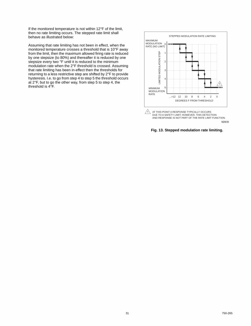
31 750-265
If the monitored temperature is not within 12°F of the limit, then no rate limiting occurs. The stepped rate limit shall behave as illustrated below:
Assuming that rate limiting has not been in effect, when the monitored temperature crosses a threshold that is 10°F away from the limit, then the maximum allowed firing rate is reduced by one stepsize (to 80%) and thereafter it is reduced by one stepsize every two °F until it is reduced to the minimum modulation rate when the 2°F threshold is crossed. Assuming that rate limiting has been in-effect then the thresholds for returning to a less restrictive step are shifted by 2°F to provide hysteresis. I.e. to go from step 4 to step 5 the threshold occurs at 2°F, but to go the other way, from step 5 to step 4, the threshold is 4°F.
Fig. 13. Stepped modulation rate limiting.
M28038
STEPPED MODULATION RATE LIMITING
DEGREES F FROM THRESHOLD
AT THIS POINT A RESPONSE TYPICALLY OCCURSDUE TO A SAFETY LIMIT; HOWEVER, THIS DETECTIONAND RESPONSE IS NOT PART OF THE RATE LIMIT FUNCTION.
...>12 12 10 6 4 2 0
4
5
2
3
1
0
8
LIM
ITE
D M
OD
ULA
TIO
N S
TE
P
MAXIMUMMODULATIONRATE (NO LIMIT)
MINIMUMMODULATIONRATE

750-265 32
Slow Start and Forced Rate limitsThe Forced Rate limit causes the burner to stay at a fixed firing rate immediately after lightoff, just after the end of the Run Stabilization time (if any). This is optionally followed by a slow start function limit that limits the ramp-up speed of the firing rate when the water is colder than a threshold. These functions will be implemented as shown in the following diagram.
Fig. 14. Slow Start and Forced Rate limits.
Table 15. Limits and Rate Override: Slow Start Limit Parameters.
Parameter CommentCH forced rate time MM:SS
This parameter determines the duration of the forced rate period, when firing for CH or LL demand. If it is set to zero then this forced rate period is disabled.
CH forced rate RPM or %This parameter provides the firing rate during the CH forced rate time. It is also the initial rate for the CH slow start period (even if the forced rate time is zero).
DHW forced rate time MM:SSThis parameter determines the duration of the forced rate period, when firing for DHW demand. If it is set to zero then this forced rate period is disabled.
DHW forced rate RPM or %This parameter provides the firing rate during the DHW forced rate time. It is also the initial rate for the DHW slow start period (even if the DHW forced rate time is zero).
PFEP/MFEP/DBI RUN STAB. FORCED RATE SLOW START MODULATION
ENDS WHEN OUTLETTEMP EXCEEDSOPERATINGSETPOINTMINUS
TURN-OFF ADJUSTMENTSTARTS WHEN FREEMODULATION BEGINS.
(0 = DISABLE)
SETPOINT = OFF HYST.
SETPOINT - OFF HYST.
A PROGRAMMABLE PARAMETER
A PROGRAMMABLE PARAMETER THAT IS NOTPART OF FORCED RATE OR SLOW START
=
=
FORCED RATE AND SLOW STARTSLOW START THRESHOLD
OUTLET
TEMPERATURE
SETPOINT
(0 = DISABLE)
IGNITION RUN
LIGHTOFF RATE
TIME
NAME
NAME
TEMP.
CH FORCED RATE
DHW FORCED RATE
CH TIME
DHW TIME
CH ENABLE
DHW ENABLE
RAMP
M28039

33 750-265
DHW high limitThe DHW high limit is a safety limit when Lockout or Recycle & Hold is selected. However, it is not a safety limit when “Suspend DHW” is selected. The DHW pump control is not a safety function.
CH slow start enable Enable, DisableThis parameter enables or disables the slow start limit function for CH and LL demand sources. It uses the CH forced rate parameter as the starting point for the slow start. If the forced rate parameter is invalid or zero and slow start is enabled, then the slow start function does not occur and an alert is issued.
DHW slow start enable Enable, DisableThis parameter enables or disables the slow start limit function for DHW demand source. It uses the DHW forced rate parameter as the starting point for the slow start. If this forced rate parameter is invalid or zero and slow start is enabled, then the slow start function does not occur and an alert is issued.
Slow start setpoint Degrees or NoneIf slow start limiting is enabled and the outlet temperature is less than the temperature provided by subtracting this number of degrees from the setpoint, then slow start rate limiting is effective. Whenever the outlet temperature is above this value, slow start limiting has no effect.
Slow start ramp RPM or % Per MinuteWhen slow start limiting is effective, the modulation rate will increase no more than the amount per minute given by this parameter.Although provided as a per-minute value, the R7910A will calculate and apply this as a stepped function using a step duration of 10 seconds.
Table 15. Limits and Rate Override: Slow Start Limit Parameters. (Continued)
Parameter Comment
Table 16. Limits and Rate Override: Outlet High Limit.
Parameter CommentDHW high limit enable Enable, Disable
This parameter enables or disables the DHW high limit function. It must be disabled when the DHW input is used as a switch to indicate DHW demand.
DHW high limit setpoint Degrees or NoneIf DHW high limit enable is enabled and the DHW temperature reaches the value given by this parameter, then a response will occur.
DHW high limit response Lockout, Recycle & HoldThis parameter selects the response.If lockout is selected then the burner control locks out.If Recycle & Hold is selected then the burner control recycles and holds until the DHW temperature falls below the DHW high limit temperature minus 5°F.
DHW high limit pump inhibit If DHW high limit enable is enabled then whenever the DHW high limit has been reached the DHW pump will be forced off. It will remain off until the DHW input temperature is lower than the DHW high limit temperature minus 5°F. The DHW high limit pump inhibit function is not a safety function.

750-265 34
AnticondensationThe anticondensation function reduces condensation effects when the temperature is below a threshold by increasing the firing rate and optionally shutting off the pump. This is not a safety function.
Anticondensation operates only when the burner is firing, and is active only if enabled for the demand source (i.e. CH, DHW) currently controlling the burner.
The pump corresponding to that source will usually be on; however, to warm the heat exchanger more quickly, that pump may be forced off when anticondensation is active.
The anticondensation parameters are as follows:
Table 17. Anticondensation Parameters.
Parameter CommentCH anticondensation enable Enable, Disable
This parameter enables or disables anticondensation for CH and LL demand.CH anticondensation setpoint Degrees or None
If CH demand anticondensation is enabled, and if CH demand or LL slave demand is in control of the burner, and the burner is firing, and if the temperature of the outlet sensor is below the temperature given by this parameter:then the anticondensation subsystem requests the burner’s firing rate to be set to the rate given by the CH maximum modulation rate. Whether this succeeds or not depends on the priority of anticondensation compared to other rate-reducing overrides (as described at the beginning of “Rate Limits and Override” on page 29).When the CH source sensor temperature reaches or exceeds the temperature given by this parameter plus a fixed hysteresis value or 4°F then this rate override ends.
CH anticondensation pump forceoff
Normal, Forced OffIf CH anticondensation is in control of the burner as described in the CH anticondensation setpoint section above, and this parameter is forced off, the CH pump is turned off to warm up the heat exchanger more quickly.However, if CH frost protection, outlet high limit, or DHW high limit are active and requesting the pump to be on, then it will remain on—these have higher priority. The pump reverts to its normal condition when anticondensation ends.
DHW anticondensation enable Enable, Disable This parameter enables or disables anticondensation for the outlet sensor when the DHW loop is in control.
DHW anticondensation setpoint Degrees or None If DHW demand anticondensation is enabled, and if DHW demand is in control of the burner, and the burner is firing, and if the temperature of the outlet sensor is below the temperature given by this parameter:• Then the anticondensation subsystem requests the burner’s firing rate to be set to the rate
given by DHW maximum modulation rate. Whether this succeeds or not depends on the priority of anticondensation compared to other rate-reducing overrides (as described at the beginning of “Rate Limits and Override” on page 29).
• When the outlet sensor temperature reaches or exceeds the temperature given by this parameter plus a fixed hysteresis value or 4°F then this rate override ends.
DHW anticondensation pump forceoff
Normal, Forced OffIf DHW anticondensation setpoint is in control of the burner as described in the DHW anticondensation temperature section above, and this parameter is forced off, the DHW pump is turned off to warm up the heat exchanger more quickly.However, if frost protection is active and requesting the pump to be on, then it will remain on—this has higher priority. The pump reverts to its normal condition when anticondensation ends.

35 750-265
Burner ControlThe Burner Control uses the following Inputs/Outputs:
InputsAll digital inputs will be conditioned to eliminate response to spurious noise and transient events while preserving the required response time of 6 line cycles or less.
FLAMEThe flame signal will be the flame status after signal conditioning, flame-on timing, and flame-off (FFRT) timing has been performed. The control’s response to loss of flame and the abnormal presence of flame will be defined by the equipment setup.
LIMIT CONTROL INPUT (LCI) (J6-3)The LCI typically includes all of the limits that cause a burner to hold or recycle. For burner control sequences that use it, a burner will not fire if the LCI input is off. If the LCI turns off during a burner run cycle it will be treated as the end of the demand.
INTERLOCK (ILK) (J5-1)The ILK input typically includes all of the limits that cause a burner to lock out if it turns off during a run cycle, must turn on within some seconds after demand is present during purge, and is ignored at other times. An example is an airflow switch. The equipment setup will define the response to this signal.
INTERRUPTED AIR SWITCH (IAS) (J6-2)The IAS input can be used to connect an airflow switch that normally opens during the Run state at low modulation rates, and thus cannot be in the interlock circuit. The equipment setup will define the response to this signal.
PRE-IGNITION INTERLOCK (PII) (J6-5)The Pre-ignition interlock typically includes a proof of closure switch from the main valve. If it is on, then the valve is closed. The PII is used in the commercial versions of the R7910A, but is ignored by the Residential version. The equipment setup will define the response to this signal.
HIGH FIRE PROVING SWITCH (HFS) (J7-2)A control may use an HFS, such as during Prepurge to prove that a damper is in the proper position or that airflow is sufficient. The equipment setup will define the response to the HFS signal.
LOW FIRE PROVING SWITCH (LFS) (J7-1)A control may use an LFS, such as during ignition to prove that a damper is in the proper position. The equipment setup will define the response to the LFS signal.
STAT, REMOTE STAT, AND LCI AS DEMAND INPUTS (J8-3)The presence of a demand may be configured to be the on condition of the Stat input, a message from a Remote Stat, the on condition of the LCI input, or may be driven by the sensor status alone. The presence of demand may typically cause pump turn-on as a primary effect, but will cause the burner control to fire only if a demand signal is also received from the Demand/Rate Selection subsystem, which is monitoring temperature. If a demand signal is received then the burner control will attempt to light the burner and if this succeeds, release control to the modulation source. However if a hold condition exists, then the burner control will remain in the hold condition until that condition reverts to normal. The status of the burner control will be reported in the Burner State and the Burner Lockout/Hold status items. The equipment setup will define the response to demand signals.
DEMANDA burner control normally will respond to the demand signal from the Demand/Rate Selection subsystem by attempting to light the burner. With success of the purge and ignition sequence, the burner control releases control to the modulation source. However, if a hold condition exists, then the burner control will remain in the hold condition until that condition reverts to normal.
OutputsMODULATION OVERRIDEThe burner control will control the modulation output when the burner is off and during burner startup and shutdown by driving the modulation rate directly, overriding the normal source for modulation control, according to this table:
During The firing rate will be set toStandby Lightoff ratePrepurge Prepurge rateIgnition (PFEP, MFEP, DSI)
Lightoff rate
Run stabilization Lightoff ratePostpurge Postpurge rateLockout Lightoff rate

750-265 36
BLOWER MOTOR (J5-6,7)The blower output will be operated to control a blower motor: the terminal will be energized at the start of prepurge and remain on through the end of postpurge, to establish airflow for those systems that require this function.
EXTERNAL IGNITION TRANSFORMER (J5-4) PILOT VALVE (J5-2) /MAIN VALVE (J5-3) AND INTERNAL SAFETY RELAY (EXT. IGN/ PV / MV/ SR)The burner control turns on the internal safety relay, the load relays and monitors their feedback to ensure that they are in the correct state. These relays provide the electrical power to energize the External Ignition Transformer, Pilot Valve and Main Valve terminals. If an output is not in its proper state, the system will respond as defined on initial Setup (typically a lockout or recycle).
FLAME VOLTAGE (TEST JACKS)This voltage will represent the flame strength using a 0 to 10V range, where 0.8 volts indicates the presence of flame.
Burner Control Safety Parameters(Established by the OEM)The following parameters may be modified only by using the process for safety data described in “Commissioning” on page 16.
The parameters occur here in their order of use in a typical burner sequence.
Table 19. Burner Control Safety Parameters.
Parameter CommentNTC sensor type 10K dual safety, 12K single non-safety
This parameter determines whether 10K or 12K sensors are used for the Inlet, Outlet, Stack, Header, and Outdoor analog sensor inputs. All sensors must be of the same type: 10K or 12K.This parameter also determines whether dual sensors are used with a cross-check for the Outlet, Stack, and DHW sensors. If “10K dual safety” is chosen, these three sensors are each dual 10K sensors, and if they do not track within 6°F then recycle and hold occurs, until the sensors are tracking again.If “12K single non-safety” is chosen, these three sensors are single 12K sensors and the tracking test is turned off (in this case external safety limits typically are required).
Power up with lockout Enable, DisableIf this parameter is set to disable then a lockout will be cleared by power-cycling the control. However, if enable is chosen, then clearing a lockout requires either:• pressing the reset pushbutton, or• activating the remote reset input, or• sending a message via Modbus or Enviracom.
LCI enable Enable, DisableIf the LCI input is enabled, then the control will check the LCI as a recycle limit. It must be on before the burner control will exit the Standby condition and LCI will cause a recycle if it turns off at other times. If this input is off and demand is present, the burner control will indicate that it is waiting for LCI so the Annunciator can provide a corresponding value in the Annunciator Hold parameter, for use by a display.
PII enable Enable, DisableIf the PII input is enabled, then the control will check the PII as a preignition interlock limit. (As defined by the equipment setup, it typically must be on before the burner control will exit the Standby condition.) If this input is off and the burner control is in a hold condition waiting for it to turn on, then the burner control will indicate that it is waiting for PII so that the Annunciator can provide a corresponding value in the Annunciator Hold parameter, for use by a display.
Interlock start check Enable, DisableIf the Interlock start check is enabled, then the control will check the ILK input as it exits the Standby condition, in response to demand. If this input is on then the burner control will hold for 120 seconds waiting for it to turn off. If this hold time expires and the ILK is still on, then a lockout occurs.
IAS start check enable Enable, DisableIf the Interrupted Air Switch Enable parameter is set to “Disable” then this parameter is ignored. Otherwise, if the IAS start check is enabled, then the control will check the IAS input as it exits the Standby condition, in response to demand. If this input is on then the burner control will hold for 120 seconds waiting for it to turn off. If this hold time expires and the IAS is still on, then a lockout occurs.

37 750-265
Interlock open response Lockout, RecycleDuring prepurge after a delay to establish airflow, and during Ignition, MFEP, and Run, the burner control requires the ILK to remain on. If it opens during Ignition, MFEP, or Run then this parameter determines the response: either a lockout or a recycle back to the Safe Start check.If recycle is selected and ILK is open during prepurge: the purge timer is set to zero and the prepurge state holds at time zero, waiting for the ILK to reclose which will resume purge timing. If this hold persists for 30 seconds then the control will go to a Standby Delay condition for 5 minutes, then try again.These responses apply to both the ILK input and the IAS input (unless the Interrupted Air Switch Enable parameter is set to “Disable”). If the burner control is in a hold condition (but not a Standby Delay) waiting for ILK to turn on, then the burner control will indicate that it is waiting for ILK so that the Annunciator can provide a corresponding value in the Annunciator Hold parameter, for use by a display.
Interrupted air switch (IAS) enable
Disable, Purge Only, Purge & IgnitionThis parameter determines when the IAS input is tested. If set to “Disable” then the IAS input is ignored by the burner control, and is used by the Annunciator. If set to “Purge Only” then IAS is monitored in the same way as the ILK input, with the same responses, during the Prepurge state. If set to “Purge & Ignition” then IAS is monitored in the same way as the ILK input, with the same responses, during the Prepurge and Ignition states.
Prepurge time MM:SSThis parameter sets the burner control’s prepurge time. Setting this parameter to zero disables prepurge.
Purge rate proving None, High Fire Switch, Fan SpeedThis parameter determines the input used to confirm the purge rate has been reached. It is unused and ignored if the Prepurge time is set to zero.If set to None, the purge rate is commanded during prepurge but purge timing begins immediately without waiting for any feedback.If set to High Fire Switch then the HFS input must be on to prove the purge rate. Additionally, if this is selected and HFS is already on upon exit from Standby then an additional 30 second prepurge delay (indicating HFS jumpered) is enforced before the measured Prepurge time begins. If the HFS opens during purge, the burner control will react as specified by the equipment setup (typically by restarting or holding Prepurge).If set to Fan Speed then the measured fan speed must be within the specified prepurge rate, +/- 3% for 3 seconds before the rate is proven and the measured prepurge time begins. If the fan speed later goes outside of the prepurge rate +/- 3% during purge, the burner control will react as specified by the equipment setup (typically by restarting or holding Prepurge).
Lightoff rate proving None, Low Fire Switch, Fan SpeedThis parameter determines the input used to confirm the rate has been reached for lighting the burner.If set to None, the lightoff rate is commanded during ignition but is not checked.If set to Low Fire Switch then the LFS input must be on to prove the lightoff rate. Additionally, if this is selected and LFS is already on upon exit from prepurge then an additional 30 second delay (indicating LFS jumpered) is enforced before the Ignition time begins. If the LFS opens during ignition, the burner control will react as specified by the equipment setup (typically by locking out).If set to Fan Speed then the measured fan speed must be within the specified lightoff rate, +/- 3% for 3 seconds before the rate is proven and Ignition begins. If the fan speed later goes outside of the prepurge rate +/- 3% during ignition or MFEP, the burner control will react as specified by the equipment setup (typically by locking out).
Pre-ignition time SecondsDuring the preignition time the igniter output is energized and the occurrence of flame is a fault condition.The purpose of this time is to prove that spark does not simulate flame. It may be set to zero if no pre-ignition time is wanted.
Pilot type Interrupted, Intermittent, DBIAn interrupted pilot turns off at the end of the main flame establishing period (MFEP), whereas an intermittent pilot remains on during the run period and thus there is no MFEP. The third choice, DBI (direct burner ignition) indicates that there is no pilot and that the main flame is lit directly using the igniter. The ignition time is fixed at 4 seconds whenever direct burner ignition is selected.
Table 19. Burner Control Safety Parameters. (Continued)
Parameter Comment

750-265 38
Fig. 15. Interrupted pilot.
Fig. 16. Intermittent pilot.
Fig. 17. Direct burner ignition
M28035
STANDBY PREPURGEPFEP
4, 10, OR 15S RUN POSTPURGE
FLAME REQUIRED.FAILURE TO IGNITE OPTIONS: • LOCKOUT • COUNT RECYCLES, THEN LOCKOUT • COUNT RECYCLES, THEN DELAY MM:SS • RECYCLE (NO LIMIT)
FLAME REQUIRED: LOCKOUT OR RECYCLE
CLEAR THE FAILURE-TO-IGNITERETRY COUNTER
=
RECYCLE DUE TOFAILURE TO IGNITE
RECYCLE DUE TO FLAMEFAILURE IN MFEP
RECYCLE DUE TO FLAMEFAILURE IN RUN
IGNITERPILOT
MAIN
PREI
GNIT
ION
(MAY
BE
ZERO
)
IGNITER MAY BE ON THROUGHOUT PFEP, OR ONLY DURING FIRST HALF.
MFEP5, 10, OR 15S
RUN STABILIZATION(MAY BE ZERO)
M28036
STANDBY PREPURGEPFEP
4, 10, OR 15S RUN POSTPURGE
FLAME REQUIRED.FAILURE TO IGNITE OPTIONS: • LOCKOUT • COUNT RECYCLES, THEN LOCKOUT • COUNT RECYCLES, THEN DELAY MM:SS • RECYCLE (NO LIMIT)
FLAME REQUIRED: LOCKOUT OR RECYCLE
CLEAR THE FAILURE-TO-IGNITERETRY COUNTER
=
RECYCLE DUE TOFAILURE TO IGNITE
RECYCLE DUE TO FLAMEFAILURE IN RUN
IGNITERPILOT
MAIN
PREI
GNIT
ION
(MAY
BE
ZERO
)
IGNITER MAY BE ON THROUGHOUT PFEP, OR ONLY DURING FIRST HALF.
RUN STABILIZATION(MAY BE ZERO)
M28037
STANDBY PREPURGEDBI
FIXED AT 4S RUN POSTPURGE
FLAME REQUIRED.FAILURE TO IGNITE OPTIONS: • LOCKOUT • COUNT RECYCLES, THEN LOCKOUT • COUNT RECYCLES, THEN DELAY MM:SS • RECYCLE (NO LIMIT)
FLAME REQUIRED: LOCKOUT OR RECYCLE
CLEAR THE FAILURE-TO-IGNITERETRY COUNTER
=
RECYCLE DUE TOFAILURE TO IGNITE
RECYCLE DUE TO FLAMEFAILURE IN RUN
IGNITERMAIN
PREI
GNIT
ION
(MAY
BE
ZERO
)
RUN STABILIZATION(MAY BE ZERO)

39 750-265
Table 19. Burner Control Safety Parameters. (Continued)
Parameter CommentIgniter on during Pilot Flame Establishing Period or First half of PFEP
This parameter is not needed and ignored if DBI (Direct Burner Ignition) is selected, because the igniter is always on throughout the timed 4 second DBI period. Otherwise the igniter may be on throughout the PFEP, or only during the first half of it:• 2 seconds for a 4 second PFEP time,• 5 seconds for a 10 second PFEP time,• 8 seconds for a 15 second PFEP time.When the igniter is external, it is on continuously during the defined period. However when the igniter is selected as the internal spark generator then, during its on time as defined by this parameter, it actually is intermittently on, then off, then on, then off, with each state lasting 1/4 second. (This is done because flame cannot be sensed while the igniter is on, due to hardware limitations, so flame sense and igniter spark are done alternatetly at a 1/4 second rate.)
Pilot flame establishing period (PFEP)
4, 10, or 15 secondsThis parameter is ignored if DBI is selected. Otherwise there are three choices for the duration of PFEP: 4, 10, or 15 seconds.Flame must be on at the end of this period or a response occurs (see “Ignite failure response” on page 39).
Main flame establishing period (MFEP)
5, 10, or 15 SecondsThis parameter only appears if Pilot type is Interrupted. Three choices of the MFEP time are provided: 5, 10, or 15 seconds.Flame must remain on throughout the MFEP, otherwise a response occurs (see “MFEP flame failure response” on page 39).
Ignite failure response Lockout, Recycle & Hold After Retries, Recycle & Lockout After Retries, Continuous RecycleIf a failure to ignite is detected at the end of the Ignition period, then there are four possible responses:• Lockout• Recycle & hold after retries—the burner control recycles to the beginning of purge and
counts how many times this has occurred. If the retry count has been reached, a hold occurs with the system purging. After the hold, the retry count is cleared and the burner tries (and retries) again.
• Recycle & lockout after retries—the burner control recycles to the beginning of purge and counts how many times this has occurred. If the retry count has been reached, a lockout occurs.
• Continuous recycle—the burner control recycles without limit.The retry counter is cleared during Standby (no demand), during the hold imposed by the retry counter, or if flame is achieved.
Ignite failure retries 3, 5This parameter provides the number of retries, either 3 or 5.
Ignite failure delay MM:SSWhen Recycle & hold after retries is selected, this parameter provides the delay time for the hold.
MFEP flame failure response Lockout, RecycleDuring the MFEP state, if the flame fails there is a choice for the response. If lockout is selected, a flame failure during MFEP causes a lockout. However, if recycle is selected, the burner control shuts off the fuel and recycles back to the beginning of prepurge, then continues with the normal burner startup process (prepurge, ignition, then run) to attempt to light the burner again.
Run flame failure response Lockout, RecycleDuring the Run state if flame fails then there is a choice for the response. If lockout is selected for flame failure during Run. However, if recycle is selected, the burner control shuts off the fuel and recycles back to the beginning of prepurge, then continues with the normal burner startup process (prepurge, ignition, then run) to light the burner again.

750-265 40
Modulation OutputThe modulation output subsystem uses as its input either the modulation rate provided by the Internal Demand/Rate Selector, which possibly is limited by a Rate Limit function, or it uses a fixed modulation rate indicated by the burner control, such as during prepurge or lightoff.
Fig. 4 in “Demand and Rate” on page 19 shows these sources. The modulation output subsystem sends a rate to one of three outputs: a fan speed control that uses a PWM output and tachometer feedback, a 4-20 mA analog signal, or a 0-10 V analog signal.
When the installer selects a fan speed system, rate parameters will be specified in RPM without regard to the burner capacity represented by a particular RPM. When one of the analog outputs is chosen, rate parameters will be specified as percentages, and in this case, the installer is thinking of this as a percent of burner capacity.
Common Modulation ParametersThese parameters are needed whenever any type of modulation is used. They are listed in the order they would be used in a burner firing sequence.
Table 19. Burner Control Safety Parameters (Continued)
Parameter CommentPilot test hold Enable, Disable
This parameter is provided to support the pilot turndown test required by burner standards for Intermittent and Interrupted pilots. It is ignored if Pilot Type is DBI.If the Pilot type is Interrupted or Intermittent and this parameter is enabled, the burner control sequence will hold (forever) at 1 second into the Ignition state.During Pilot Test Hold, a flame-out timer always starts at zero when the Ignition state is entered, then counts up toward 15 seconds while flame is off and down toward zero when flame is on. This timer has a possible effect only during the pilot test: if it ever reaches 15 seconds of accumulated flame out time then a lockout occurs.The pilot test hold should be enabled prior to entering Ignition, since changes to parameters may require some seconds to take effect. Similarly, when the hold is disabled the burner control may remain in the hold condition for a short time.
BLR functionIgnition source
Blower MotorInternal, ExternalThe Falcon can use either an internal spark generator, an external ignition source driven via relay contacts that are interlocked with the main valve and powered through the ILK input terminal. The Falcon operates circuits according to the setting of these parameters; thus if the igniter circuit that is operated differs from the one actually installed, no ignition will occur.
Run stabilization time MM:SSDuring run stabilization the modulation rate is held at the light-off rate and is released for modulation only after the hold time given by this parameter has expired. If this parameter is zero then there is no stabilization time.
Postpurge time 0 seconds to 5 minutes (MM:SS)This parameter sets the burner control’s postpurge time. Setting this parameter to zero disables postpurge.

41 750-265
Fan Speed Modulation ParametersThese parameters are used only when fan speed is selected as the modulation output.
Table 21. Modulation Output Parameters.
Parameter CommentModulation output Fan Speed, 4-20mA, 0-10V
This parameter selects the type of modulation output. The Falcon software responds by driving the appropriate circuit to provide modulation of firing rate.This parameter also affects the interpretation or the type of all parameters which specify rates. These may be provided either as motor RPM or as percentage values, depending on the type of modulation output selected.The implementation of these two different types will share no common representations with the exception of zero, which will mean both zero as an RPM and also zero as a percent modulation (this provides a useful initial or default value). Any other non-zero value will be legal only as a fan speed, or as a percent, but not both. Thus if a system is set up using fan speed values, and then the modulation output parameter is changed to select one of the analog outputs, then all of the fan speeds become “Invalid” except for those that are zero. Similarly, parameters that were set up as percentages are invalid when interpreted as fan speeds.Whenever a function requires a rate parameter it will test this parameter for a legal value, and if an invalid value is found it will respond by generating either an Alert or a Lockout, as appropriate to the function, and by either suspending operation or operating in an alternative manner, as appropriate to the function.
Prepurge rate RPM or %This parameter specifies the analog output or fan speed used during prepurge.
Lightoff rate RPM or %This parameter specifies the analog output or fan speed used during ignition.
Firing rate control Auto, Manual in Run, Manual in Run and StandbyIf this parameter is set to either of the manual options, then the burner’s firing rate during modulation in the Run state is the rate given by the Manual firing rate parameter. If the Manual in Run and Standby option is chosen, the firing rate output is also controlled by the manual firing rate parameter during the Standby condition; however this applies only to the normal, idle Standby condition and not to a Standby Hold condition, wherein the burner is preparing to fire but cannot leave standby because of something abnormal. In the latter case the rate is driven by the burner control sequencer. However, a manual rate does not generate demand—to fire at this rate demand must be present from another source. When set to “Auto” the manual firing rate parameter is ignored.
Manual firing rate RPM or %This parameter specifies the analog output or fan speed during burner modulation, when firing rate control specifies manual mode.
CH Maximum modulation rateDHW Maximum modulation rateMinimum modulation rate
RPM or %These parameters provide the limits of analog output, fan speed for CH, and fan speed for DHW during modulation.
Postpurge rate RPM or %This parameter specifies the analog output or fan speed used during postpurge.
Table 22. Fan Speed Modulation Parameters.
Parameter CommentAbsolute maximum fan speed RPM
The fan will never be proper to operate above the RPM provided by this parameter, regardless of the rate request.
Absolute minimum fan speed RPMThe fan will never be proper to operate below the RPM provided by this parameter, regardless of the rate request, except by commanding it to turn off.
PWM frequency 1000Hz, 2000Hz, 3000Hz, 4000Hz, This parameter provides the frequency used by the PWM output to control the fan.

750-265 42
Analog Modulation ParametersThese parameters are used only when 4-20mA or 0-10V is selected for modulation output.
Pump ControlThe pump control system operates three pumps identified as Pump A, Pump B, and Pump C. There are multiple pump control functions which may be attached to any of these pump outputs. If a function is not attached to a pump, then it has no effect except that it still will provide input to another pump function.
It is possible (although not necessarily useful) to attach multiple functions to the same pump. If this occurs then the pump will be on if either function requests the pump to be on (i.e. a logical OR).
Central Heating (CH) PumpThe CH pump function is implemented as shown in Fig. 18.
The CH pump function turns on with overrun time for CH demand and LL slave demand, assuming that the burner is neither locked out nor in an anti short cycle delay, however, these are optionally forced off by CH anticondensation. The CH pump turns on without force-off and using a separate overrun timer for CH frost protection. It turns on with neither force-off nor overrun when outlet high limit is active.
Fan gain up 1-100This is the gain for speeding up the fan.
Fan gain down This is the gain for slowing down the fan.Fan speed-up ramp RPM per second
Whenever the burner is firing it will be commanded to increase its RPM no faster than the rate provided by this parameter.
Fan slow-down ramp RPM per secondWhenever the burner is firing it will be commanded to decrease its RPM no faster than the rate provided by this parameter.
Fan min duty cycle duty%The fan modulation output will never send a duty cycle lower than this threshold, except for a 0% duty cycle to turn the fan off.This can be used to limit the minimum PWM to a level that prevents stalling of the fan. During start-up conditions the fan speed is monitored by the burner control which will react if it is not correct. Additionally, during Run if an out-of-range fan speed is reported for more than 3 seconds then the burner control will recycle back to Standby (and try again).
Table 23. Fan Speed Modulation Parameters.
Parameter CommentmA modulation slopemA modulation interceptV modulation slopeV modulation intercept
nThese parameters support factory calibration of the current and voltage outputs by specifying the slope and intercept of the function that can be used to convert the desired output into the appropriate PWM duty cycle.
Analog output hysteresis nThis parameter adjusts the amount of hysteresis appliled to the PID output when a non-PWM modulation is selected. The "n" value determines how much the PID is required to change in a new direction before the output will change.This is somewhat experimental, although simulation shows this technique provides better response and also better control of motor reversals than a deadband.A typical range is 0 (disabled) to 10, although higher values are allowed. The amount of PID change required to change direction is computed as:n/10 * Pgain * P scalerBackground: The granularity of temperature measurement in the Falcon is 0.1C, which is represented internally as an integer (e.g. C * 10). Thus if the temperature changes by the smallest measurable amount (e.g. 1 count), per P term of the PID output will contribute a change of 1*Pgain * P scaler, to the total PID output. The parameter thus allows some fraction of this change to be the threshold for changing direction, e.g. "n" = 5 means0.5 or half of this amount of change would be needed to change direction. If the Igain is zero then using any value of "n" less than 10 makes no difference; however when Igain is non-zero it also contributs to the PID output, so smaller amounts of hysteresis make sense. Experimentally, values of between 5 to 10 seem to work well.
Table 22. Fan Speed Modulation Parameters. (Continued)
Parameter Comment

43 750-265
Fig. 18. CH pump implementation.
Domestic Hot Water (DHW) PumpThe DWH pump function is implemented as shown in Fig. 19.
The DHW pump function turns on with overrun time for DHW demand, assuming that the burner control is not locked out, although this turn-on is delayed by a start delay time if the
burner is not already firing. This turn-on is also optionally forced off by DHW anticondensation. The DHW pump turns on without force-off and using a separate overrun timer for DHW frost protection. It is forced off when DHW high limit is active, except that manual control may still turn it on.
Table 24. CH Pump Parameters.
Parameter CommentCH Pump Output None, Pump A, Pump B, Pump C
This parameter allows the CH pump function to be disconnected or to be attached to any of the pump outputs.
CH Pump Control On, AutoThe CH pump can be turned on manually, or it can be set to operate automatically. If it is turned on, it remains on until changed back to Auto.In Auto mode it operates according to the demand sources listed for CH Pump Output and the overrun time.
CH Pump Overrun Time MM: SSThis time indicates how long the CH pump should continue to run after CH pump demand or LL slave demand ends.
M28030
DEMAND PRIORITY = CH
CH ANTI-COND ENABLED
CH ANTI-COND ACTIVE
CH ANTI-COND “PUMP OFF” SELECTED
BOILER PUMPHAS ITS OWNOVERRUN TIMER
DEMAND PRIORITY = LL
CH PUMPOUTPUTFORCE OFF
CH
LL SLAVE
IF THE PUMP IS NOTFORCED OFF AND ITSHOULD BE ON,THEN TURN IT ON.
BURNER STATE = OK• NOT INTERNAL FAULT• NOT DISABLED (E.G. BURNER SWITCH)• NOT DISABLED BY PARAM ERROR• NOT LOCKED OUT• NOT ANTI-SHORT-CYCLE
CH PUMP CONTROL: ON
(SELECTIONS ARE:ON/AUTO)
AUXILIARY PUMPHAS ITS OWNON/AUTO CONTROL
OUTLET HIGHLIMIT ACTIVE
HIGH LIMITS ANDMANUAL CONTROLDO NOT CAUSEOVERRUN TIME
CH FROST PROTECTION PUMP DEMAND
EXERCISE PUMP DEMAND
PARAMETER
OTHER NAMES ARE INTERNAL SIGNALS.
CONNECTION TO PUMP A, B, OR C
1–9 ON/OFF PRIORITY.CIRCLED NUMBERS ARE REASONS WHY PUMP IS ON.NUMBERS WITHIN SQUARES ARE REASONS WHY PUMP IS OFF.THE LOWEST NUMBERED REASON THAT EXPLAINS THEACTUAL PUMP CONDITION IS USED.
BOILER PUMPDEMAND ANDSTATUS FROM CH
AUXILIARY PUMPDEMAND AND STATUSFROM CH
EXERCISE PUMP ONLY IFIT IS NOT FORCED OFF.
TURN ON THE PUMPFOR CH DEMAND ORLL SLAVE DEMAND. LOAD
OVERRUN TIME
CLEAR (INHIBIT)
INHIBIT OVERRUNIF FORCED OFF.
LOAD
OVERRUN TIME
FROST PROTECTIONAND OVERRUNTO BOILER PUMP
LL SLAVE BURNER DEMAND
3
4
9
6
7
5
1
2
8

750-265 44
Fig. 19. DHW pump implementation.
System PumpThe System pump function is implemented as shown in Fig. 20.
The System pump function turns on with overrun time for LL master pump demand. If the LL master STAT Input Enable parameter is enabled then this demand exists if the Stat input
is on and the master has one or more available slaves (firing or not); if disabled then this pump demand exists if the master is sending demand and rate to an available slave (which is firing or preparing to fire). A slave command can also turn on the pump, either with or without overrun time and it can be turned on by the exercise pump function.
Table 25. DHW Pump Parameters.
Parameter CommentDHW Pump Output None, Pump A, Pump B, Pump C
This parameter allows the DHW pump function to be disconnected or to be attached to any of the pump outputs.
DHW Pump Control On, AutoThe DHW pump can be turned on manually, or it can be set to operate automatically. If it is turned on, it remains on until changed back to Auto.
DHW Pump Start Delay MM:SSWhen DHW demand changes from off to on, this delay time is used to delay the start of the DHW pump. The pump starts after the delay expires, assuming that DHW demand is still present. This delay does not occur, however, if the burner is already firing when DHW gains control of it.
DHW Pump Overrun Time MM:SSThis time indicates how long the DHW pump should remain on after DHW demand ends.
DHW ANTI-COND ENABLED
DHW ANTI-COND ACTIVE
BOILER PUMPDEMAND AND
STATUS FROM DHW
BOILER PUMPHAS ITS OWN
OVERRUN TIMER
DEMAND PRIORITY= DHW
DHWPUMPOUTPUT
DHW PUMP CONTROL: ON
(SELECTIONS ARE: ON/AUTO)
AUXILIARY PUMPDEMAND AND STATUSFROM DHW
AUXILIARY PUMPHAS ITS OWNON/AUTO CONTROL
DHW HIGHLIMIT ACTIVE
HIGH LIMITINHIBITS THEPUMP.
DHW FROST PROTECTION PUMP DEMAND
LOAD EXPIRED
START DELAY
FORCE OFF
EXERCISE PUMP DEMAND
DON’T EXERCISEPUMP IF FORCEDOFF OR STARTDELAY IS INPROGRESS.
LOADOVERRUN TIME
INHIBIT OVERRUNIF FORCED OFF. LOAD
OVERRUN TIME
CLEAR (INHIBIT)
TURN ON THE PUMPFOR DHW DEMAND(AFTER DELAY) OROVERRUN.
BURNER IS FIRING FORCE EXPIRED
ANTI-SHORT-CYCLEDELAY INACTIVE OR
NOT APPLICABLE
DHW ANTI-COND “PUMP OFF” SELECTED
FROST PROTECTIONAND OVERRUNTO BOILER PUMP
M28031
PARAMETER
OTHER NAMES ARE INTERNAL SIGNALS.
CONNECTION TO PUMP A, B, OR C
1–9 ON/OFF PRIORITY.CIRCLED NUMBERS ARE REASONS WHY PUMP IS ON.NUMBERS WITHIN SQUARES ARE REASONS WHY PUMP IS OFF.THE LOWEST NUMBERED REASON THAT EXPLAINS THEACTUAL PUMP CONDITION IS USED.
9
7
8
6
4
5
1
3
2
BURNER STATE = OK• NOT INTERNAL FAULT• NOT DISABLED (E.G. BURNER SWITCH)• NOT DISABLED BY PARAM ERROR• NOT LOCKED OUT
IF THE PUMP IS NOTFORCED OFF AND ITSHOULD BE ON,THEN TURN IT ON.

45 750-265
Fig. 20. System pump implementation.
Boiler PumpThe Boiler pump function is implemented as shown in Fig. 21.
The Boiler pump function turns on whenever pump demand exists from any source. It has its own overrun time if LL, CH, or DWH is the demand source. For CH frost protection and DHW frost protection it turns on and follows the overrun time provided by those sources. It also turns on with no overrun when the outlet high limit or DHW high limit is active.
Table 26. System Pump Parameters.
Parameter CommentSystem Pump Output None, Pump A, Pump B, Pump C
This parameter allows the System function to be disconnected or to be attached to any of the pump outputs.
System Pump Control On, AutoThe System pump can be turned on manually, or it can be set to operate automatically. If it is turned on, it remains on until changed back to Auto.In Auto mode it operates according to the LL master and slave demand and overrun time.
System Pump Overrun Time MM:SSThis time indicates how long the System pump should remain on after the LL master or slave pump demand with overrun ends.
M28032
SYSTEM PUMPOUTPUT
SYSTEM PUMP CONTROL: ON
(SELECTIONS ARE: ON/AUTO)
EXERCISE PUMP DEMAND
LOAD
OVERRUN TIME
12B
3
2A
LL MASTER PUMP DEMAND(WILL NOT OCCUR UNLESSMASTER IS ENABLED)
SLAVE COMMAND FORSYSTEM PUMP, NO OVERRUN
SLAVE COMMAND FORSYSTEM PUMP, WITH OVERRUN
5
4
PARAMETER
OTHER NAMES ARE INTERNAL SIGNALS.
CONNECTION TO PUMP A, B, OR C
1–4 ON PRIORITY.

750-265 46
Fig. 21. Boiler pump implementation.
Auxiliary PumpThe Auxiliary pump function is implemented as shown in Fig. 22.
The Auxiliary pump function turns on whenever the CH or DHW pumps are on. It is off when neither of these is on.
This function has no parameter for overrun time; it inherits all of its behavior related to overrun, frost protection, high limits, and anticondensation by simply following the CH and DHW pumps.
Table 27. Boiler Pump Parameters.
Parameter CommentBoiler Pump Output None, Pump A, Pump B, Pump C
This parameter allows the Boiler pump function to be disconnected or to be attached to any of the pump outputs.
Boiler Pump Control On, AutoThe Boiler pump can be turned on manually, or it can be set to operate automatically. If it is turned on, it remains on until changed back to Auto.In Auto mode it operates according to the demand and overrun time.
Boiler Pump Overrun Time Minutes: SecondsThis time indicates how long the Boiler pump should remain on after demand ends.
BOILER PUMPOUTPUT
BOILER PUMPDEMAND FROM CH
BOILER PUMPDEMAND FROM DHW
BOILER PUMP CONTROL: ON
(SELECTIONS ARE: ON/AUTO)
CH PUMP WOULD BE ON,BUT IT IS FORCED OFF CHBY ANTI-CONDENSATION
DHW PUMP WOULD BE ON,BUT IT IS FORCED OFF DHWBY ANTI-CONDENSATION
DHW FROST PROTECT PUMP DEMAND
OUTLET HIGH LIMIT ACTIVE
EXERCISE PUMP DEMAND
BOILER PUMP ISFORCED OFF BY CH
BOILER PUMP ISFORCED OFF BY DHW
THESE DO NOT INTERACT, BECAUSE THEY AREMUTUALLY EXCLUSIVE (ULTIMATELY DRIVEN BY“DEMAND PRIORITY” WHICH SELECTS ONLYONE OR THE OTHER).
CH FROST PROTECT PUMP DEMAND
DON’T EXERCISE PUMP IFCH/DHW IS FORCED OFF.
DON’T EXERCISE PUMP IFCH/DHW IS FORCED OFF.
INHIBIT OVERRUNIF FORCED OFF.
CH FROST PROTECT PUMP OVERRUN
DHW FROST PROTECT PUMP OVERRUN
LOADOVERRUN TIME
CLEAR (INHIBIT)
PARAMETER
OTHER NAMES ARE INTERNAL SIGNALS.
CONNECTION TO PUMP A, B, OR C
1–9 ON/OFF PRIORITY.CIRCLED NUMBERS ARE REASONS WHY PUMP IS ON.NUMBERS WITHIN SQUARES ARE REASONS WHY PUMP IS OFF.THE LOWEST NUMBERED REASON THAT EXPLAINS THEACTUAL PUMP CONDITION IS USED.
9
10
11
1
5
6
7
8
4
12
3
2
M28033

47 750-265
Fig. 22. Auxiliary pump implementation.
Pump ExercisingEach of the pumps (A, B, and C) will have an exercise timer that helps to ensure that pumps do not “freeze up” due to long periods of no use. However, this is active only if the pump is attached to some function: a pump output that is not attached is not exercised.
For pumps that are attached, whenever the pump is off, a timer will measure the pump-off time. When the day counter reaches the value provided by the Pump Exercise Interval (Days) parameter, then the pump will be turned on for the time given by the Pump Exercise Time parameter.
Whenever the pump is on, for any reason, the counter is set to zero to begin a new measurement.
Table 28. Auxiliary Pump Parameters.
Parameter CommentAuxiliary Pump Output None, Pump A, Pump B, Pump C
This parameter allows the Auxiliary pump function to be disconnected or to be attached to any of the pump outputs.
Auxiliary Pump On When CH Pump is On, DHW Pump is On, Either CH or DHW Pump is OnThis parameter determines which pump output is coupled to the Auxiliary pump function: CH, DHW, or either of these. If the latter is selected then the Auxiliary pump is controlled by ORing the two output functions.
Auxiliary Pump Control On, AutoThe Auxiliary pump can be turned on manually, or it can be set to operate automatically. If it is turned on, it remains on until changed back to Auto.
AUXILIARYPUMPOUTPUT
AUXILIARY PUMP CONTROL: ON
(SELECTIONS ARE: ON/AUTO)
AUXILIARY PUMP DEMANDFROM CH AND CH STATUS
AUXILIARY PUMP DEMANDFROM DHW AND DHW STATUS
EXERCISE PUMP DEMAND
AUX PUMP STATUS FROM CH = CH PUMP WOULD BE ONBUT IS FORCED OFF
AUX PUMP STATUS FROM DHW = DHW PUMP WOULD BE ONBUT IS FORCED OFF
SLAVE COMMAND FORAUXILIARY PUMP
“CH...” OR “EITHER...”
DHW...” OR “EITHER...”
ON WHEN:• SLAVE COMMAND ONLY• CH PUMP IS ON• DHW PUMP IS ON• EITHER CH OR DHW PUMP IS ON
DON’T EXERCISE PUMP IFCH/DHW IS FORCED OFF.
6
5
7
3
4
21
PARAMETER
OTHER NAMES ARE INTERNAL SIGNALS.
CONNECTION TO PUMP A, B, OR C
1–9 ON/OFF PRIORITY.CIRCLED NUMBERS ARE REASONS WHY PUMP IS ON.NUMBERS WITHIN SQUARES ARE REASONS WHY PUMP IS OFF.THE LOWEST NUMBERED REASON THAT EXPLAINS THEACTUAL PUMP CONDITION IS USED.
M28034
Table 29. Pump Exercising Parameters.
Parameter CommentPump Exercise Interval (Days) 0, or N
If set to zero, the exercise function is disabled. Otherwise this parameter provides the interval time between exercising the pumps. It is common to all three pump outputs (A, B, and C).
Pump Exercise Time MM:SSIf the time is zero then the exercise function is disabled. Otherwise this parameter provides the time that a pump should be on to exercise. It is common to all three pump outputs (A, B, and C).

750-265 48
ANNUNCIATORThe Annunciator section monitors the status of a series string of limits, control, and interlock contacts to enhance fault and status messages.
The Annunciator’s 8 inputs (A1–A8) along with the Interlock, LCI, and Pre Ignition Interlock inputs, provide a total of 11 monitored contact components.
The Annunciator function can be set up as:• Disabled: Not used at all• Fully enabled: Status of all inputs shown, even those
designated unused.• Enabled with unused designated terminals hidden.
Each Annunciator input has three parameters:
• Long Name: 20 characters long; name is displayed when viewing the Annunciator status from a system display like the S7999B.
• Short Name: 3 characters long; used for status viewing by more limited local displays, like the S7910. The short name can also be used as part of a lockout or hold message.
• Location: Each Annunciator terminal location may be designated:
• LCI: Monitored after the demand is present throughout the Run period, and following the system action designated by LCI setup parameter (Lockout or Recycle).
• ILK: Monitored with the demand input (LCI) and annunciate which interlock is causing the system to remaining in “Standby”.
• PII: Interlocks (typically indicating the gas valve status) monitored from the end of a call for heat, up to the Ignition Trial Period of the next demand cycle (including standby) then ignored during Run.
• Unused: not used
• Other: Used to Monitor a circuit, not related to any of the above.
The input terminal names (Interlock, LCI, Pre Ignition Interlock) can be renamed with a long (20 character) and short (3 character) name that better describes their purpose. This only applies for monitoring. System demands for annunciation (lockout or standby hold for example) will retrieve the Interlock, LCI or Pre Ignition Interlock name for annunciation.
Three Annunciator terminals may already be assigned functions based on the system parameter setup:
• A1: Will be Interrupted Air Switch (IAS) if the parameter is enabled.
• A7: Will be High Fire Switch (HFS) if the parameter for Purge Rate Proving parameter is enabled
• A8: Will be Low Fire Switch (LFS) if Lightoff Rate Proving parameter is enabled.
Annunciator ExampleFig. 23 is an example of wiring to the Annunciator terminals and names that have been assigned for this example.
Note that the assigned terminals (LCI, ILK, and PII) are the last interlocks in their category.

49 750-265
Fig. 23. Example of annunciator inputs and terminal names.
SortingAnnunciator items are sorted first by their category assignment. The category order is:
LCI, ILK, PII, Other (Unused items appearing in the Other category)
Within the category, inputs are sorted by the input identifier (A1–A8), with the additional rule that LCI (if enabled) is last in the LCI category, ILK last in the ILK category, and PII (if enabled) is last in the PII category.
Viewing the 833-3577 System Display using the “programmable” annunciator display in this case would resemble Fig. 24.
Fig. 24. Annunciator display.
If A7 is defined as a HFS input, then the parameter that calls it a “Security door” would be ignored and the automatic value for the A8 LFS and A1 IAS).
(High Fire Switch) is used instead (the same would be true
ANNUNCIATOR NAMES
MASTER SWITCH
WATER LEVEL
LIMIT CONTROL
MASTERSWITCH
WATERLEVEL
LIMIT CONTROL
LCI
ILK
A1
L1
A2
STACK VENT FAN
HIGH GAS PRESSURE
LOW GAS PRESSURE
AIRFLOW SWITCH
STACKVENT
HIGH GASPRESSURE
LOW GASPRESSURE
AIRFLOW
A5
A3
A4
A8
UPSTREAM VALVE
DOWNSTREAM VALVE
SECURITY DOOR
AIR COMPRESSOR
DOOR
COMPRESSOR
M28040
A7
A6
PII
PIIV1
PIIV2
TERMINAL TABLE
A1 J6-2A2 J6-1LCI J6-3A3 J7-6A4 J7-5A5 J7-4ILK J5-1A6 J7-3PII J6-5A7 J7-2A8 J7-1


51 750-265
FAULT HANDLING
Lockouts and AlertsThe CB Falcon implements two kinds of faults: lockouts and alerts.
A list of fault codes with possible troubleshooting tips is provided in Table 45 on page 99.
A list of alerts is provided in Table 39 on page 89.
LOCKOUT• A lockout causes the boiler control to shutdown and
requires manual or remote reset to clear the lockout.• Always causes alarm contacts to close.• Logged in lockout history.
ALERT• Every other kind of problem that isn't a lockout is an alert.
Examples include boiler control abnormal holds, LL master problems, faults from non-safety functions, etc. The Falcon will include alerts for all abnormal events that are relevant to an operator or end user.
• When an alert occurs, it is a one-time event. Alerts never require manual intervention to reset them; that is, if the alert clears up, then normal operation will continue. An alert is not a condition, it is an event. The cause of the alert may be a condition, e.g. something that is causing an abnormal hold, but the alert itself in this case is a momentary event generated upon entry to that condition.
• Whether the alarm contact closes or not is programmable for each alert by the OEM.
• Alerts are logged in a 15-item volatile alert history sorted in chronological order. Only one instance of each alert fault code occurs in the history, corresponding to the most recent occurrence of the alert.
Alarms for AlertsThe Alarm Parameter Control Block (see the section above) determines which alerts will cause an alarm (by closing the alarm contacts) and which will be reported silently.
Thus an alarm might be on because of a lockout or an alert. If the cause is a lockout then the alarm contacts remain close until the lockout is cleared. However, for alarms due to alerts (which may recur) the alarm may be silenced for a period of time (0–600 minutes) by specifying it in the Alarm Silence Time parameter.
Sensor Signal ConditioningThe analog sensors signal includes filtering to reduce the effect of noise and spurious read events. This filter includes averaging to smooth sensor output and reject occasional spurious values to prevent them from affecting the average. The Falcon subsystems implement a startup delay to allow sensors to be read multiple times before they are used, to prime the filtering.
Sensors won’t cause a fault condition unless the value is requested for control purposes. Thus it is not a fault for a sensor to be absent or otherwise non-operational unless it is used for something.
If its value is requested and a sensor fault exists, then an alert condition is triggered by the requestor in response to the fault status, unless this is either a normal operating condition (e.g., the DHW sensor used as a switch) or causes a lockout (e.g., a failed high limit sensor).
Safety sensors include the comparison of redundant sensors. If a safety sensor mismatch occurs this is reported to the caller as a fault (which will cause the operator to take an appropriate action).
Sensor faults will include:
• out-of-range: low• out-of-range: high—distinguishing low vs. high is
important when sensor inputs are being used as digital on/off inputs; in this case these out-of-range values are not faults.
• mismatch—applies to safety sensors, where two sensors are compared.
Sensor fault status will include hysteresis to prevent non-persistent events from affecting fault status. This hysteresis will provide a failed sensor response less than 1 second.

750-265 52
BURNER CONTROL OPERATION
Safety Shutdown of Burner Control FunctionsSafety Shutdown (Lockout) occurs if any of the following occur during the indicated period:
1. INITIATE Period:a. A/C line power errors occurred.b. Four minute INITIATE period has been exceeded.
2. STANDBY Period:a. Flame signal is present after 240 seconds.b. Preignition Interlock is open an accumulative time of
30 seconds.c. Interlock Start check feature is enabled and the
Interlock String (including Airflow Switch) is closed for 120 seconds with the controller closed. (jum-pered or welded Interlock).
d. Pilot Valve Terminal is energized.e. Main Valve Terminal is energized.f. Internal system fault occurred.
3. PREPURGE Period:a. Preignition Interlock opens anytime during
PREPURGE period.b. Flame signal is detected for 10 seconds accumu-
lated time during PREPURGE.c. Purge Rate Fan RPM or High Fire Switch fails to
close within four minutes and fifteen seconds after the firing rate motor is commanded to drive to the high fire position at the start of PREPURGE.
d. Light off Rate Fan RPM or Low Fire Switch fails to close within four minutes and fifteen seconds after the firing rate motor is commanded to drive to the low fire position at the end of PREPURGE.
e. Lockout Interlock (if programmed) does not close within 10 seconds.
f. Lockout Interlock opens during PREPURGE.g. Pilot Valve terminal is energized.h. Main Valve terminal is energized.i. Internal system fault occurred.
4. PRE-IGNITION TIMEa. Lockout Interlock opens.b. IAS Purge and Ignition enabled and the Interlock
opens.c. Preignition Interlock opens.d. Pilot Valve terminal is energized.e. Main Valve terminal is energized.
5. PILOT FLAME ESTABLISHING PERIOD (PFEP)a. Low Fire Switch opens (if enabled).b. Lockout Interlock opens (if enabled).c. Pilot Valve terminal is not energized.d. No flame is present at the end of the PFEP, or after
programmed number of retry attempts.e. Main valve terminal is energized.f. Internal system fault occurred.
6. MAIN FLAME ESTABLISHING PERIOD (MFEP).a. Low Fire Switch opens (if enabled).b. Lockout Interlock opens (if enabled).c. Pilot valve terminal is not energized.d. Main valve terminal is not energized.e. No flame present at the end of MFEP.f. Internal system fault occurred.
7. RUN Period:
a. No flame is present, or flame is lost (if enabled-lock-out).
b. Lockout Interlock opens) if enabled).c. IAS Purge and Ignition enabled and the Interlock
opens.d. Pilot terminal energized (if programmed as Inter-
rupted Pilot).e. Main valve terminal is not energized.f. Internal system fault occurred.
8. POSTPURGE Period.a. Preignition Interlock does not close in five seconds.b. Pilot Valve terminal is energized.c. Main Valve terminal is energized.d. Internal system fault occurred.e. Flame sensed 240 seconds accumulated time after
the RUN period.
Operational Sequence
Central HeatingINITIATEThe R7910 enters the Initiate sequence on Initial Power up or:• Voltage fluctuations vary +10%/-15%.• Frequency fluctuations vary +/-10%.• If Demand, LCI, or Stat interrupt (open) during the
Prepurge Period.
The Initiate sequence also delays the burner motor from being energized and de-energized from an intermittent AC line input or control input.
If an AC problem exist more than 240 seconds a lockout will occur.
Start-up sequence central heating request (system in standby):
1. Heat request detected (On Setpoint - On Hysteresis).2. The DHW pump is switched off to prevent the water in
the DHW tank from being cooled-down.3. The Circulating pump is switched on. If the “pump off”
function for CH-mode is selected, the pump stays off or will be switched off.
4. After a system Safe Start Check, the Blower (fan) is switched on after a dynamic ILK switch test (if enabled).

53 750-265
5. After the ILK switch is closed and the purge rate proving fan RPM is achieved (or High Fire Switch is closed) - prepurge time is started.
6. When the purge time is complete, the purge fan RPM is changed to the Lightoff Rate or if used, the damper motor is driven to the Low Fire Position.
7. As soon as the fan-rpm is equal to the light-off rpm (+/- 200 rpm) (or the Low Fire Switch closes), the Trial for Ignition or Pre-Ignition Time is started (depending on hardware selection).
8. Pre-Ignition Time will energize the ignitor and check for flame.
9. Trial for Ignition. Fig. 15–17 on page 38 are three igni-tion options. Specifics for timings and device actions were defined by the OEM.
10. The ignition and the gas valve are switched on.11. The ignition is turned off at 0.3 seconds before the end
of the Trial for Ignition period, so the ignition-energy with a combined electrode is released in time.
12. To check the flame signal (at the end of the safety time) the fan is set to start-RPM during the stabilization time.
13. Before the release to modulation, the fan is switched to minimum RPM for the CH Forced Rate and Slow Start Enable, if the water is colder than the threshold.
14. The hysteresis off is increased with 50°F (10°C) during 60 seconds.
15. At the end of the CH-heat request the burner is switched off and the fan stays on until post purge is complete.
16. A new CH-request is blocked for the forced off time set by the Anti Short Cycle (if enabled).
17. The pump stays on during the pump overrun time (if enabled).
18. At the end of the pump overrun time the pump will be switched off.
Domestic Hot WaterINITIATEThe Falcon enters the INITIATE sequence on Initial Power up or:• Voltage fluctuations vary +10%/-15%.• Frequency fluctuations vary +/-10%.• If Demand, LCI, or Stat interrupt (open) during the 16. At the end of the pump overrun time the pump will be
Prepurge Period. switched off.
The INITIATE sequence also delays the burner motor from being energized and de-energized from an intermittent AC line input or control input.
If an AC problem exists more than 240 seconds a lockout will occur.
Start-up sequence DHW-request (system in standby):1. Heat request detected (either DHW Sensor Only, DHW
Sensor and Remote Command or DHW Switch and Inlet Sensor, whichever applies).
2. The pump is switched on (after the DHW Pump Start Delay).
3. After a system Safe Start Check, the Blower (fan) is switched on after a dynamic ILK switch test (if enabled) has verified the ILK is open.
4. After the ILK switch closes and the purge rate proving fan RPM is achieved (or High Fire Switch is closed) - prepurge time is started.
5. When the prepurge time is complete, the purge fan RPM is changed to the Lightoff Rate or if used, the damper motor is driven to the Low Fire Position).
6. At the end of the Prepurge time, the fan-rpm set to the start-rpm +/- 200 rpm or the Low Fire Switch input is proven. Ignition Trials begin.
7. Trial for Ignition. Fig. 15–17 on page 38 are three igni-tion options. Specifics for timings and device actions were defined by the OEM.
8. The ignition and the gas-valve are switched on.9. The ignition is turned off at 0.3 seconds before ending
the PFEP (MFEP), so the ignition-energy with a com-bined electrode is released in time.
10. Verification of the flame will release R7910A to Run and modulation.
11. A slow start can be present prior to Run, depending on the setting for the DHW Slow Start Enable parameter.
12. The system is now in Run.13. At the end of the DHW-heat request the burner is
switched off and the blower output stays on and the fan is adjusted to postpurge rate to complete postpurge.
14. A new DHW-request is blocked for the time set by the anti short cycle time.
15. The pump stays on during the pump overrun time.

750-265 54
PARAMETER GLOSSARY
Table 30. Parameter Glossary.
Parameter Name Short Description Ref. PageAbsolute max fan speed
The fan will never be commanded to operate above the RPM provided by this parameter, regardless of the rate request.
41
Absolute min fan speed
The fan will never be commanded to operate below the RPM provided by this parameter, regardless of the rate request, except by commanding it to turn off.
41
Alarm silence time Alarms can be silenced for the amount of time given by this parameter. 51Analog output hysteresis
When modulating via 0-10V or 4-20mA, changes in the direction of PID output can be limited by a small amount of hysteresis, to decrease the occurrence of actual control reversals.
42
Annunciation enable This parameter determines whether the Annunciator features of the R7910 are active. When disabled, the R7910 will ignore the Annunciator inputs (because the application does not use this feature).
18
Annunciator 1 location
The location of the contacts monitored by the A1 annunciator input. 48
Annunciator 1 long name
The long name (up to 20 characters) of the A1 annunciator input. 48
Annunciator 2 location
The location of the contacts monitored by the A2 annunciator input. 48
Annunciator 2 long name
The long name (up to 20 characters) of the A2 annunciator input. 48
Annunciator 3 location
The location of the contacts monitored by the A3 annunciator input. 48
Annunciator 3 long name
The long name (up to 20 characters) of the A3 annunciator input. 48
Annunciator 4 location
The location of the contacts monitored by the A4 annunciator input. 48
Annunciator 4 long name
The long name (up to 20 characters) of the A4 annunciator input. 48
Annunciator 5 location
The location of the contacts monitored by the A5 annunciator input. 48
Annunciator 5 long name
The long name (up to 20 characters) of the A5 annunciator input. 48
Annunciator 6 location
The location of the contacts monitored by the A6 annunciator input. 48
Annunciator 6 long name
The long name (up to 20 characters) of the A6 annunciator input. 48
Annunciator 7 location
The location of the contacts monitored by the A7 annunciator input. 48
Annunciator 7 long name
The long name (up to 20 characters) of the A7 annunciator input. 48

55 750-265
Annunciator 8 location
The location of the contacts monitored by the A8 annunciator input. 48
Annunciator 8 long name
The long name (up to 20 characters) of the A8 annunciator input. 48
Annunciator mode The annunciator may be fixed, in which the labels and locations of the inputs is pre-assigned, or programmable in which these things may be altered.
48
Annunciator1 short name
The short (3 letter) name of the contacts monitored by the A1 annunciator input. 48
Annunciator2 short name
The short (3 letter) name of the contacts monitored by the A2 annunciator input. 48
Annunciator3 short name
The short (3 letter) name of the contacts monitored by the A3 annunciator input. 48
Annunciator4 short name
The short (3 letter) name of the contacts monitored by the A4 annunciator input. 48
Annunciator5 short name
The short (3 letter) name of the contacts monitored by the A5 annunciator input. 48
Annunciator6 short name
The short (3 letter) name of the contacts monitored by the A6 annunciator input. 48
Annunciator7 short name
The short (3 letter) name of the contacts monitored by the A7 annunciator input. 48
Annunciator8 short name
The short (3 letter) name of the contacts monitored by the A8 annunciator input. 48
Anticondensation > Delta-T
Anti-condensation (rate increase) may have a higher or lower priority than Delta-T (rate decrease), when both of these are active and competing.
34
Anticondensation > Forced rate
Anti-condensation (rate increase) may have a higher or lower priority than forced rate (a specific firing rate), when both of these are active and competing.
34
Anticondensation > Outlet limit
Anti-condensation (rate increase) may have a higher or lower priority than Outlet high limit (rate decrease), when both of these are active and competing.
34
Anticondensation > Slow start
Anti-condensation (rate increase) may have a higher or lower priority than slow start (a specific firing rate slope), when both of these are active and competing.
34
Anticondensation > Stack limit
Anti-condensation (rate increase) may have a higher or lower priority than Stack high limit (rate decrease), when both of these are active and competing.
34
Anti short cycle time Whenever the burner is turned off due to no demand the anti-short-cycle timer is started and the burner remains in a Standby Delay condition waiting for this time to expire. Does not apply, however, to recycle events or DHW demand.
18
Auxiliary pump control
The Auxiliary pump can be turned on manually, or it can be set to operate automatically. If it is turned on then it remains on until changed back to Auto. In Auto mode it operates according to the pump function that it is assigned to.
46
Auxiliary pump cycle count
Auxiliary pump cycle count. Can be written to a new value (e.g. if the pump or controller is replaced).
5
Auxiliary pump on when
This parameter assigns the Auxiliary pump to a particular function. 46
Auxiliary pump output
This parameter allows the Auxiliary pump function to be disconnected or to be attached to any of the pump outputs.
46
BLR function This parameter selects either a blower motor function for the BLR output terminal. 36Boiler pump control The Boiler pump can be turned on manually, or it can be set to operate automatically. If it is
turned on then it remains on until changed back to Auto. In Auto mode it operates according to the demand and overrun time.
45
Boiler pump cycle count
Boiler pump cycle count. Can be written to a new value (e.g. if the pump or controller is replaced).
5
Boiler pump output This parameter allows the Boiler pump function to be disconnected or to be attached to any of the pump outputs.
45
Table 30. Parameter Glossary.
Parameter Name Short Description Ref. Page

750-265 56
Boiler pump overrun time
This time indicates how long the Boiler pump should remain on after demand ends. 45
Burner cycle count Burner cycle count. Incremented upon each entry to Run. Can be written to a new value (e.g. if the burner or controller is replaced).
5
Burner name This parameter allows each control to have a unique name. 18Burner run time Burner run time. Measures the time spent in the Run state. Can be written to a new value
(e.g. if the burner or controller is replaced).4
Burner switch This parameter enables or disables the burner control. When it is off, the burner will not fire. 17CH anticondensation enable
This parameter enables or disables anti-condensation for CH and LL demand. 34
CH anticondensation pump Force Off
If CH anti-condensation is in control of the burner and this parameter is Forced off, then the CH pump is turned off to warm up the heat exchanger more quickly.
34
CH anticondensation setpoint
If CH anti-condensation is enabled, has priority, CH or LL slave is firing the burner, and the outlet temperature is below this parameter then the firing rate set to the Maximum modulation rate until the temperature exceeds this by 4 degrees F.
34
CH D gain This gain applied to the Differential term of the PID equation for the CH loop. 24CH demand source The source of CH loop control can be specified to use different inputs. 22CH enable This parameter determines whether the CH loop is enabled or disabled. When disabled the
demand caused by the sensor assigned to the CH loop is ignored. It may be disabled to turn it off temporarily, or because the application does not use this feature.
18
CH forced rate For CH demand, if the CH forced rate time is non-zero, then the firing rate will be held at the rate specified here during that time. This parameter is also needed as the starting point for Slow State, even if the forced rate time is zero.
32
CH forced rate time For CH demand, if this time is non-zero then, upon entry to Run, the firing rate will be held at the CH forced rate.
32
CH frost protection enable
The CH frost protection feature can be enabled to turn the CH pump and possibly fire the burner whenever the CH input sensor is too cold.
27
CH hysteresis step time
The time needed for one step of hysteresis shift, when the off hysteresis threshold or on hysteresis threshold is shifted due to a burner-on or burner-off event, respectively. Zero disables this function.
23
CH I gain This gain applied to the Integral term of the PID equation for the CH loop. 24CH maximum modulation rate
Provides the upper limit of analog output or fan speed during modulation when firing for CH or LL slave mode.
41
CH ODR boost max setpoint
For CH demand and when outdoor reset is active, the setpoint will be boosted if demand is not met after a period of time. This parameter provides the upper limit for boosting the setpoint.
24
CH ODR boost time For CH demand and when outdoor reset is active, the setpoint will be boosted if demand is not met after a period of time. This parameter provides the upper limit for boosting the setpoint.
24
CH ODR max outdoor temperature
This parameter determines the maximum outdoor temperature for the CH outdoor reset graph. At the maximum outdoor temperature the setpoint will be the minimum water temperature.
24
CH ODR min outdoor temperature
This parameter determines the X coordinate of one point on the ODR graph. At this outdoor temperature the setpoint will be the CH setpoint (or the CH TOD setpoint, if TOD is on).
24
CH ODR min water temperature
This parameter provides the CH setpoint when the outdoor reset temperature is at its defined maximum.
24
CH off hysteresis The off hysteresis is added to the CH setpoint to determine the temperature at which this demand turns off
23
CH on hysteresis The on hysteresis is subtracted from the Setpoint to determine the temperature at which demand turns on.
23
Table 30. Parameter Glossary.
Parameter Name Short Description Ref. Page

57 750-265
CH outdoor reset enable
If outdoor reset is enabled then the current outdoor temperature is used to determine the Setpoint by interpolation using CH Setpoint (or CH Time-Of-Day Setpoint if TOD is on), the min water temperature, and the min and max outdoor temperatures.
24
CH P gain This gain applied to the proportional term of the PID equation for the CH loop. 24CH pump control The CH pump can be turned on manually, or it can be set to operate automatically. If it is
turned on then it remains on until changed back to Auto. In Auto mode it operates according to the demand sources listed above and the overrun time.
43
CH pump cycle count
CH pump cycle count. Can be written to a new value (e.g. if the pump or controller is replaced).
5
CH pump frost protection overrun time
This time indicates how long the CH pump should remain on after frost protection demand ends. That is, whenever the pump has been on due to frost protection and then this demand ends, it always continues to run for the time given by this parameter.
28
CH pump output This parameter allows the CH pump function to be disconnected or to be attached to any of the pump outputs.
43
CH pump overrun time
This time indicates how long the CH pump should remain on after demand from any source ends. That is, whenever the pump has been on, but the last requests for the pump to be on ends, it always continues to run for the time given by this parameter.
43
CH sensor The sensor used for modulation and demand may be either the Outlet sensor or the Header sensor input.
22
CH setpoint This Setpoint is used when the time-of-day input is off. If the ODR function is active, this Setpoint provides one coordinate for the outdoor reset curve, as described for the CH Outdoor Reset parameter.
22
CH slow start enable
This parameter enables or disables the slow start limit function for CH (or LL slave) demand.
33
CH tod setpoint This Setpoint is used when the time-of-day input is on. If the ODR function is active, this Setpoint provides one coordinate for the shifted (because TOD is on) outdoor reset curve, as described for the CH Outdoor Reset parameter.
23
Delta-T degrees If the outlet is hotter than the inlet temperature by the amount given by this parameter, the response defined for the Delta-T Limit Response will occur. Stepped Modulation Limiting will occur as the temperature approches this limit..
29
Delta-T delay This parameter provides the delay time for the Delta-T limit. 29Delta-T enable This parameter enables or disables the entire delta-T limit function. 29Delta-T response If the temperature difference exceeds the limit and Recycle && delay is selected then the
burner control recycles and holds while waiting for a delay (see the Delta-T Limit Delay parameter) to expire.
29
Demand rate interval time
This is the time in milliseconds between iterations of the demand/rate task. 21 (for CH)24 (for DHW)
DHW anticondensation enable
This parameter enables or disables anti-condensation for the DHW sensor. 34
DHW anticondensation pump force off
If DHW anti-condensation is in control of the burner and this parameter is Forced off, then the DHW pump is turned off to warm up the heat exchanger more quickly.
34
DHW anticondensation setpoint
If DHW anti-condensation is enabled, has priority, DHW is firing the burner, and the outlet is below the temperature given by this parameter then the firing rate set to the Maximum modulation rate until the temperature exceeds this this by 4 degrees F.
34
DHW D gain This gain applied to the Differential term of the PID equation for the DHW loop. 26DHW demand source
The source of DHW loop control can be specified to use different inputs. 26
DHW enable This parameter determines whether the DHW loop is enabled or disabled. When disabled the demand caused by the DHW sensor is ignored. It may be disabled to turn it off temporarily or because the application does not use this feature.
18
DHW forced rate For DHW demand, if the DHW forced rate time is non-zero, then the firing rate will be held at the rate specified here during that time. This parameter is also needed as the starting point for Slow State, even if the forced rate time is zero.
32
Table 30. Parameter Glossary.
Parameter Name Short Description Ref. Page

750-265 58
DHW forced rate time
For DHW demand, if this time is non-zero then, upon entry to Run, the firing rate will be held at the DHW forced rate.
32
DHW frost protection enable
The DHW frost protection feature can be enabled to turn the DHW pump and possibly fire the burner whenever the DHW input sensor is too cold.
28
DHW priority vs.CH
This parameters determines the priority of DHW vs. the CH call-for-heat, when both of these are enabled and active. (If DHW has a lower priority, it may be boosted to the highest priority temporarily via the DHW Priority Time paremeter.)
18
DHW priority vs.LL
This parameters determines the priority of DHW vs. the LL slave call-for-heat, when both of these are enabled and active. (If DHW has a lower priority, it may be boosted to the highest priority temporarily via the DHW Priority Time paremeter.)
Not available at this time.
DHW high limit enable
This parameter enables or disables the DHW high limit function. It must be disabled when the DHW input is used as a switch to indicate DHW demand.
33
DHW high limit response
If Recycle && hold is selected, the burner control recycles and waits for the DHW temperature to fall. It will remain in this holding condition until the DHW temperature is lower than the DHW high limit temperature minus 5 degrees F.
33
DHW high limit setpoint
If the DHW temperature reaches the value given by this parameter then a response will occur.
33
DHW hysteresis step time
The time needed for one step of hysteresis shift, when the off hysteresis threshold or on hysteresis threshold is shifted due to a burner-on or burner-off event, respectively. Zero disables this function.
26
DHW I gain This gain applied to the Integral term of the PID equation for the DHW loop. 26DHW maximum modulation rate
Provides the upper limit of analog output or fan speed during modulation when firing for DHW.
41
DHW off hysteresis The off hysteresis is added to the DHW Setpoint to determine the temperature at which DHW demand turns off
26
DHW on hysteresis The on hysteresis is subtracted from the DHW Setpoint to determine the temperature at which DHW demand turns on.
26
DHW P gain This gain applied to the Proportional term of the PID equation for the DHW loop. 26DHW priority time If this parameter is non-zero then a DHW demand will take priority over other demand
sources for the specified time. If this persists for longer than this time the priority will expire. The timer is reset when demand from the DHW source turns off.
18
DHW pump control The DHW pump can be turned on manually, or it can be set to operate automatically. If it is turned on then it remains on until changed back to Auto. In Auto mode it operates according to the DHW demand, the start delay timer and the overrun time.
44
DHW pump cycle count
Can be written to a new value (e.g. if the pump or controller is replaced). 5
DHW pump frost protection overrun time
This time indicates how long the DHW pump should remain on after frost protection demand ends. That is, whenever the pump has been on due to frost protection and then this demand ends, it always continues to run for the time given by this parameter.
28
DHW pump output This parameter allows the DHW pump function to be disconnected or to be attached to any of the pump outputs.
44
DHW pump overrun time
This time indicates how long the DHW pump should remain on after demand from any source ends. That is, whenever the pump has been on, but the last requests for the pump to be on ends, it continues to run for the time given by this parameter.
44
DHW pump start delay
When DHW demand changes from off to on, this parameter delays the start of the DHW pump. No delay occurs when DHW demand acquires control (due to priority) of a burner that is already firing for CH or LL slave demand.
44
DHW setpoint This Setpoint is used whenever the time-of-day switch is off or not connected (unused). 26DHW slow start enable
This parameter enables or disables the slow start limit function for DHW demand. 33
DHW tod setpoint This Setpoint is used when the time-of-day switch is on. 26
Table 30. Parameter Glossary.
Parameter Name Short Description Ref. Page

59 750-265
Fan during off cycle rate
If this parameter is non-zero for a control that is enabled as a LL slave, then it provides the modulation rate (e.g. fan speed) that should be used when the LL master indicates this burner should be off but should run its fan at the off cycle rate.
Fan gain down This parameter determines how aggressively the fan controller changes the fan duty cycle when the fan should slow down. It is the gain of a first-order filter (e.g. it is the I gain of a PID control in which the P and D gains are always zero).
42
Fan gain up This parameter determines how aggressively the fan controller changes the fan duty cycle when the fan should speed up. It is the gain of a first-order filter (e.g. it is the I gain of a PID control in which the P and D gains are always zero).
42
Fan min duty cycle Whenever a variable speed fan is on it will never receive a duty cycle less than this parameter's value. It should be set to the duty cycle at which the fan is guaranteed to keep spinning (after it has started) so that it will never stall.
42
Fan slow down ramp
Whenever the burner is firing it will be commanded to decrease its RPM no faster than the rate provided by this parameter.
42
Fan speed up ramp Whenever the burner is firing it will be commanded to increase its RPM no faster than the rate provided by this parameter.
42
Firing rate control If one of the manual modes is chosen then the Manual Rate parameter controls the firing rate during the specified states.
41
Flame sensor type Different kinds of flame detectors may be used. This parameter tells the control what type of sensor is installed.
Flame threshold The flame threshold can be adjusted to match various kinds of flame detectors and equipment. It is specified in tenths of volts, where 0.1V = 0.1 microamp for a flame rod.
IAS start check enable
This parameter enables a start check for the Interrupted Air Switch input. If enabled, this input must be off before leaving Standby, to prove that it is not shorted..
36
Ignite failure delay When Recycle && hold after retries is selected as the response for an ignition failure, this parameter provides the delay time for the hold.
39
Ignite failure response
If ignition fails then several responses are possible. This parameter selects one of these responses.
39
Ignite failure retries This parameter provides the number of retries for an ignition failure, if the response to failure of ignition includes retries.
39
Igniter on during The igniter may be on throughout the pilot establishing period, or only during the first half of it (early ignition termination). Ignored if DBI is selected.
39
Ignition source Several outputs may be selected as the ignition source. This parameter selects one of these.
40
ILK long name The long name (up to 20 characters) of the ILK annunciator input. 48ILK short name The short (3 letter) name of the contacts monitored by the ILK annunciator input. 48Installation data The installer may edit this parameter to provide installation information. 19Interlock open response
During prepurge after a delay to establish airflow and during Ignition, MFEP, and Run, the burner control requires the ILK to remain on. If it opens during these times, this parameter determines the response: either a lockout or a recycle.
37
Interlock start check enable
If enabled, the control will check the ILK input as it exits the Standby condition in response to demand. If on, the burner control will hold waiting for it to turn off. If this hold time expires and the ILK is still on, a lockout occurs.
36
Interrupted air switch enable
This parameter enables the Interrupted Air Switch input. If enabled it is tested in the same way and during the same states as the ILK input.
37
LCI enable The LCI input may be enabled as a recycle interlock, or this may be disabled. (It is normal to disable the LCI here if it is to be used as a demand input for the CH control loop.)
36
LCI long name The long name (up to 20 characters) of the LCI annunciator input. 48LCI short name The short (3 letter) name of the contacts monitored by the LCI annunciator input. 48
Table 30. Parameter Glossary.
Parameter Name Short Description Ref. Page

750-265 60
Lead lag hysteresis step time
The time needed for one step of hysteresis shift, when the off hysteresis threshold or on hysteresis threshold is shifted due to a burner-on or burner-off event, respectively. Zero disables this function.
Not available at this time.
Lead lag I gain Gain applied to the integral term of the PID equation for the LL master. Not available at this time.
Lead lag master enable
This parameter determines whether the Falcon will operate as a lead lag master on the local Modbus.
Not available at this time.
Lead lag master stat input enable
If enabled then the STAT input provides an overall demand input for the LL master. When STAT is off then the LL master will operate the slave burners, but when it is off the master will turn off all slave burners.
Not available at this time.
Lead lag off hysteresis
The off hysteresis is added to the LL master's setpoint to determine the temperature at which this demand turns off
Not available at this time.
Lead lag on hysteresis
The on hysteresis is subtracted from the LL master's setpoint to determine the temperature at which this demand turns on.
Not available at this time.
Lead lag outdoor reset enable
If outdoor reset is enabled then the current outdoor temperature is used to determine the Setpoint by interpolation using LL Setpoint (or LL Time-Of-Day Setpoint if TOD is on), the min water temperature, and the min and max outdoor temperatures.
Not available at this time.
Lead lag P gain Gain applied to the proportional term of the PID equation for the LL master. Not available at this time.
Lead lag sequence type
The Lead Lag master may operate according to several sequencing algorithms. This parameter selects one of these.
Not available at this time.
Lead lag setpoint This Setpoint is used when the time-of-day input is off. If the ODR function is active, this Setpoint provides one coordinate for the outdoor reset curve, as described for the LL Outdoor Reset parameter.
Not available at this time.
Lead lag slave enable
This parameter determines whether the CB Falcon will operate as a lead lag slave. Not available at this time.
Lead lag tod setpoint
This Setpoint is used when the time-of-day input is on. If the ODR function is active, this Setpoint provides one coordinate for the shifted (because TOD is on) outdoor reset curve, as described for the LL Outdoor Reset parameter.
Not available at this time.
Lightoff rate This parameter specifies the analog output or fan speed used during Ignition. 41Lightoff rate proving This parameter specifies the input used to confirm the Prepurge rate has been reached. 37LL ODR boost max setpoint
For LL demand and when outdoor reset is active, the setpoint will be boosted if demand is not met after a period of time. This parameter provides the upper limit for boosting the setpoint.
Not available at this time.
LL ODR boost time For LL demand and when outdoor reset is active, the setpoint will be boosted if demand is not met after a period of time. This parameter provides the upper limit for boosting the setpoint.
Not available at this time.
LL ODR max outdoor temperature
This parameter determines the maximum outdoor temperature for the LL outdoor reset graph. At the maximum outdoor temperature the setpoint will be the minimum water temperature.
Not available at this time.
LL ODR min outdoor temperature
This parameter determines the X coordinate of one point on the ODR graph. At this outdoor temperature the setpoint will be the LL setpoint (or the LL TOD setpoint, if TOD is on).
Not available at this time.
LL ODR min water temperature
This parameter provides the LL setpoint when the outdoor reset temperature is at its defined maximum.
Not available at this time.
Manual firing rate This parameter specifies the analog output or fan speed during burner modulation, when the Firing rate control parameter specifies Manual mode.
41
MFEP This parameter provides choices for the duration of the MFEP (main flame establishing period) time. Flame must remain on throughout the MFEP or a response occurs. Not needed and ignored unless the Pilot type is Interrupted.
39
MFEP flame failure response
If flame fails in the Main Flame Establishing Period and recycle is selected then the burner control recycles back to the beginning of Prepurge, then continues with the normal burner startup process to attempt to light the burner again.
39
Minimum modulation rate
Provides the lower limit of analog output or fan speed during modulation. 41
Table 30. Parameter Glossary.
Parameter Name Short Description Ref. Page

61 750-265
Minimum stage off time
Whenever the LL master turns off a stage, it will remain off for at least the amount of time specified here, before it is requested to turn on again.
Not available at this time.
Modulation output This parameter selects the modulation output. The Falcon software responds by driving the appropriate circuit to provide modulation of firing rate.
41
NTC sensor type The sensors used may all be the 10K NTC type in which safety sensors are redundant, or all be a 12K NTC type in which no sensors are redundant and external temperature limit devices are required. The latter is for MCBA retrofit compatibility.
36
OEM identification The OEM may provide identification information here. 19Outdoor frost protection setpoint
This parameter provides the setpoint for frost protection based on outdoor temperature. When the outdoor temperature falls below this threshold then frost protection will be active.
Outlet high limit response
If Recycle && hold is selected, the burner control recycles and waits for the outlet temperature to fall. It will remain in this holding condition until the outlet temperature is lower than the outlet high limit temperature minus 5 degrees F.
30
Outlet high limit setpoint
If the outlet temperature reaches the value given by this parameter, a response will occur. 30
Outlet T-rise degrees
If the T-Rise limit is active and the outlet temperature rises faster than this number of degrees per minute, then the burner will recycle and delay for a specified time.
34
Outlet T-rise delay This parameter provides the delay time before the burner will again attempt to fire, when an outlet T-rise limit has occurred.
35
Outlet T-rise limit enable
This parameter enables or disables the outlet T-rise limit. 35
PFEP This parameter provides choices for the duration of the pilot flame establishing period. Flame must be on at the end of this period. This parameter is ignored if DBI (Direct Burner Ignition) is selected.
39
PID iteration frequency
PID iteration frequency. This parameter determines how many executions of the demand/rate task occur between executions of the PID control algorithm.
PII enable This parameter enables the Pre-Ignition Interlock input. If disabled the PII input is ignored. 36PII long name The long name (up to 20 characters) of the PII annunciator input. 48PII short name The short (3 letter) name of the contacts monitored by the PII annunciator input. 48Pilot test hold If the Pilot type is Interrupted or Intermittent and this parameter is enabled then the burner
control sequence will hold (forever) at 1 second into the Ignition state, while monitoring the flame via a 15 second timer.
40
Pilot type Interrupted pilot turns off after MFEP (main flame establishing period). Intermittent pilot remains on during the Run period (no MFEP). DBI (direct burner ignition) indicates the main flame is lit directly using a 4 second ignition period.
37
Postpurge rate This parameter specifies the analog output or fan speed used during Postpurge. 41Postpurge time This parameter sets the burner control's postpurge time. Setting this parameter to zero
disables prepurge.40
Power up with lockout
If Enable is chosen, then if the control is in the lockout condition when it powers up, it will remain that way. Disable means that power cycling the control will clear a lockout.
36
Preignition time During the Preignition time the igniter output is energized and the occurrence of flame is a fault condition. It can be used to heat up a hot-surface igniter or to prove that spark does not simulate flame. Set to zero to disable.
37
Prepurge rate This parameter specifies the analog output or fan speed used during Prepurge. 41Prepurge time This parameter sets the burner control's prepurge time. Setting this parameter to zero
disables prepurge.37
Pulses per revolution
The number of pulses per revolution of the fan is provided by this parameter. (Typically it is the number of Hall-effect sensors that the fan contains.)
Pump exercise interval
This parameter specifies the maximum number of days that a pump can be off. If this limit is reached then the pump is turned on for the specified exercise time. If the interval is zero then this exercise function is disabled.
47
Pump exercise time This parameter specifies the amount of time that a pump remains on, when it has been turned on due to the exercise interval. If this time is zero then the exercise function is disabled.
47
Table 30. Parameter Glossary.
Parameter Name Short Description Ref. Page

750-265 62
Purge rate proving This parameter specifies the input used to confirm the Prepurge rate has been reached. 37PWM frequency This parameter provides the frequency of the pulse-width modulation for variable speed fan
control.41
Run flame failure response
If flame fails in Run and recycle is selected then the burner control recycles back to the beginning of Prepurge, then continues with the normal burner startup process to attempt to light the burner again.
39
Run stabilization time
During run stabilization the modulation rate is held at the Lightoff Rate parameter setting and is released for modulation only after the hold time given by this parameter has expired. If this parameter is zero then there is no stabilization time.
40
Slave mode Each slave burner can specify how it should be handled by the Lead Lag master's sequencer. This parameter selects one of those methods.
Not available at this time.
Slave priority When a slave burner is Used First or Used Last, it's order of use vs. other burners also having the same slave mode can be set using this parameter, to give each slave a different priority.
Not available at this time.
Slow start ramp When slow start limiting is effective, the modulation rate will increase no more than the amount per minute given by this parameter.
33
Slow start setpoint If slow start limiting is enabled and the outlet temperature is less than the temperature provided by this parameter, slow start rate limiting is effective, whereas whenever the outlet temperature is above this value, slow start limiting has no effect.
33
Spark Voltage Spark voltage configuration for Safety uCStack limit delay This parameter provides the delay time for the Stack limit. 30Stack limit enable This parameter enables or disables the entire stack temperature limit function. 30Stack limit response For Recycle and Delay, the burner control recycles and holds while waiting for a delay (see
the Stack Limit Delay parameter) to expire, and after the delay it tries again.30
Stack limit setpoint If the stack temperature exceeds the temperature given by this parameter then the response defined for the Stack Limit Response parameter will occur. As the temperature approaches this limit, the Stepped Modulation Limiting function is active.
30
System pump control
The Boiler pump can be turned on manually, or it can be set to operate automatically. If it is turned on then it remains on until changed back to Auto. In Auto mode it operates according to the demand and overrun time.
45
System pump cycle count
System pump cycle count. Can be written to a new value (e.g. if the pump or controller is replaced).
5
System pump output
This parameter allows the System pump function to be disconnected or to be attached to any of the pump outputs.
45
System pump overrun time
This time indicates how long the System pump should remain on after demand ends. 45
Temperature units This parameter determines whether temperature is represented in units of Fahrenheit or Celsius degrees.
18
Table 30. Parameter Glossary.
Parameter Name Short Description Ref. Page

750-265 68
CB Falcon GLOBAL MODBUSThe following definitions are used in this section:
Modbus: Application layer communication protocol standard adopted by the Modbus-IDA trade association. Recognized as an industry standard protocol for RS-485 serial communication.
PCB: Parameter Control Block. Files that customize the user interface with the Falcon. PCBs reside in the non-volatile storage in the Falcon and are uploaded from the R7910A into the user interface.
PIM: Plug In Module. Plug that can be inserted into the R7910A to enable Lead Lag and to backup and restore parameter settings in the CB Falcon.
RTU: Remote Terminal Unit serial transmission mode. Mode used to encode data for Modbus where each 8-bit byte is sent as two 4-bit hexadecimal characters.
The Falcon Global Modbus port is a 3-pin connector that interfaces to the following RS-485 signals:

69 750-265
Serial transmission mode on the Global Modbus network is RTU mode. Message format has the following characteristics::
The CB Falcon Global Modbus interface supports the following function codes:• 03 (0x03) Read Holding Registers• 06 (0x06) Write Single Register• 16 (0x10) Write Multiple Registers• 17 (0x11) Report Slave ID
All of the configuration and status data are accessed as 16-bit holding registers in this interface. Since all CB Falcon digital signals accessed in this interface are read-only, these digital signals are mapped to bits within holding registers instead of coils or discrete inputs to simplify the interface. Variable length data are also represented by holding registers, and therefore, must be accessed individually and not as part of a group. The length of the variable length data is returned in the response. All 32-bit data items are accessed as two consecutive 16-bit holding registers, i.e., each item uses 2 register address spaces.
The holding register map is defined in the following table. Except for variable length data items the registers can be accessed as a single register or up to 20 registers for writes and 125 registers for reads. Data is mapped into logical groups with room for future expansion so some gaps exist in the register map.
Data organization is intended to allow for efficient register access. Status data is organized into register blocks by application function and a function status change indicator is used to denote when any data has changed within the register block since the last time the registers were read (see the following figure). The CB Falcon sets the status change indicator bit when at least one of the registers in the functional block has changed value since it was last read. The Global Modbus master can read the status change register and determine which functional register blocks have changed value since it’s last access and only read those register blocks. The Global Modbus master can ignore the status change register and poll status data as it deems fit.
Fig. 25. Register map.
Table 32. RS-485 Signals.
Signal TerminalData + (a) 1Data - (b) 2Common (c) 3
Coding system 8-bit binaryNumber of data bits per character
10 =1 start bit8 data bitsNo parity bit1 stop bit
Bit transfer rate 38400 bpsDuplex Half duplexError checking 2 byte CRC-16 polynomialBit transfer order LSB firstEnd of message Idle line for 3.5 or more
characters
M28108
SYSTEM STATUS
TREND STATUS
BURNER CONTROL STATUS
SENSOR STATUS
DEMAND & MODULATION STATUS
CENTRAL HEAT (CH) STATUS
DOMESTIC HOT WATER (DHW) STATUS
PUMP STATUS
STATISTICS
LEAD LAG STATUS
SYSTEM CONFIGURATION
MODULATION CONFIGURATION
CENTRAL HEAT (CH) CONFIGURATIONPUBLIC
BURNER CONTROL CONFIGURATION
FAN CONFIGURATION
PUMP CONFIGURATION
ANNUNCIATION CONFIGURATION
DOMESTIC HOT WATER (DHW) CONFIGURATION
LIMITS CONFIGURATION
ANTICONDENSATION CONFIGURATION
OUTDOOR RESET (ODR) CONFIGURATION
FROST PROTECTION CONFIGURATION
LEAD LAG CONFIGURATION
SAFETY CONFIGURATION
LOCKOUT HISTORY
ALERT LOG
PIM PUBLIC

750-265 70
0000 0000 Status Change R U16 Register is cleared (all bits zeroed) after read. Identifies register groups that have new status in them.Bit map:15-11=Reserved (always 1)10=Alert log9=Lockout history8=Lead Lag status7=Statistics6=Pump status5=DHW status4=CH status3=Demand&Modulation status2=Sensor status1=Burner control status0=Active Lockout
0001 0001 Configuration Change R U16 Register is cleared (all bits zeroed) after read. Identifies register groups that have new data in them.Bit map:15=PCB configuration14=PIM configuration13=Safety configuration12=Lead Lag configuration11=Frost protection configuration10=Outdoor reset configuration9=Anticondensation configuration8=Limits configuration7=DHW configuration6=Annunciation configuration5=Pump configuration4=Fan configuration3=Burner control configuration2=CH configuration1=Modulation configuration0=System configuration
0002 0002 Digital I/O R U16 Bit map:15=Safety relay14=Time of Day13=STAT (Demand)12=High Fire Switch (HFS)11=Low Fire Switch (LFS)10=Load Control Input (LCI)9=Pre-ignition interlock (PII)8=Interlock (ILK)7=Alarm6=Main valve5=Pilot valve4=External ignition3=Blower motor/HSI2=Pump C1=Pump B0=Pump A
Table 33. CB Falcon Global Modbus Register Map
Address (hex)
Register (dec) Parameter
Read/Write Format Note

71 750-265
0003 0003 Annunciation I/O R U16 Only applicable when Annunciation is enabledBit map:15-8=Reserved (always 0)7=Annunciator 86=Annunciator 75=Annunciator 64=Annunciator 53=Annunciator 42=Annunciator 3/LFS1=Annunciator 2/HFS0=Annunciator 1/IAS
0004 0004 Limits R U16 Bitmap:15-4=Reserved (always 0)3=Delta T limit2=Stack limit1=DHW high limit0=Outlet high limit
0005 0005 PIM status R U16 Bit map:15-11=Reserved10=OEM alert PCB stored in PIM9=OEM range PCB stored in PIM8=OEM parameter PCB stored in PIM7-2=Reserved1=Lead/Lag enabled0=PIM installed
TREND STATUS0006 0006 Demand source R U16 Current demand source:
0=Unknown1=No source demand2=CH3=DHW,4=Lead Lag5=CH frost protection6=DHW frost protection7=No demand due to burner switch (register 199) turned off
0007 0007 Outlet temperature R U16 -40°-130° (0.1°C precision)1
0008 0008 Firing rate R U16 Actual firing rate (%2 or RPM3).0009 0009 Fan speed R U16 RPM000A 0010 Flame signal R U16 0.01V or 0.01μA precision
(0.00-15.00V)000B 0011 Inlet temperature R U16 -40°-130° (0.1°C precision)1
000C 0012 DHW temperature R U16 -40°-130° (0.1°C precision)1
000D 0013 Outdoor temperature R U16 -40°-130° (0.1°C precision)1
000E 0014 Stack temperature R U16 -40°-130° (0.1°C precision)1
000F 0015 Header temperature R U16 -40°-130° (0.1°C precision)1
0010 0016 Active CH setpoint R U16 -40°-130° (0.1°C precision)1 Setpoint determined by CH setpoint source (register 65).
0011 0017 Active DHW setpoint R U16 -40°-130° (0.1°C precision)1 Setpoint determined by DHW setpoint source (register 81).
0012 0018 Active LL setpoint R U16 -40°-130° (0.1°C precision)1 Setpoint determined by LL setpoint source (register 161).
Table 33. CB Falcon Global Modbus Register Map. (Continued)
Address (hex)
Register (dec) Parameter
Read/Write Format Note
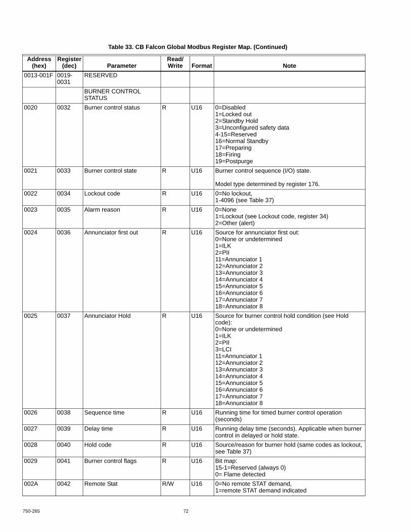
750-265 72
0013-001F 0019-0031
RESERVED
BURNER CONTROL STATUS
0020 0032 Burner control status R U16 0=Disabled1=Locked out2=Standby Hold3=Unconfigured safety data4-15=Reserved16=Normal Standby17=Preparing18=Firing19=Postpurge
0021 0033 Burner control state R U16 Burner control sequence (I/O) state. Model type determined by register 176.
0022 0034 Lockout code R U16 0=No lockout,1-4096 (see Table 37)
0023 0035 Alarm reason R U16 0=None1=Lockout (see Lockout code, register 34)2=Other (alert)
0024 0036 Annunciator first out R U16 Source for annunciator first out:0=None or undetermined1=ILK2=PII11=Annunciator 112=Annunciator 213=Annunciator 314=Annunciator 415=Annunciator 516=Annunciator 617=Annunciator 718=Annunciator 8
0025 0037 Annunciator Hold R U16 Source for burner control hold condition (see Hold code):0=None or undetermined1=ILK2=PII3=LCI11=Annunciator 112=Annunciator 213=Annunciator 314=Annunciator 415=Annunciator 516=Annunciator 617=Annunciator 718=Annunciator 8
0026 0038 Sequence time R U16 Running time for timed burner control operation (seconds)
0027 0039 Delay time R U16 Running delay time (seconds). Applicable when burner control in delayed or hold state.
0028 0040 Hold code R U16 Source/reason for burner hold (same codes as lockout, see Table 37)
0029 0041 Burner control flags R U16 Bit map:15-1=Reserved (always 0)0= Flame detected
002A 0042 Remote Stat R/W U16 0=No remote STAT demand,1=remote STAT demand indicated
Table 33. CB Falcon Global Modbus Register Map. (Continued)
Address (hex)
Register (dec) Parameter
Read/Write Format Note

73 750-265
002B-002F 0043-0047
RESERVED
SENSOR STATUS0030 0048 Outlet sensor state R U16 0=None, 1=Normal, 2=Open, 3=Shorted, 4=Outside
high range, 5=Outside low range, 6=Not reliable0031 0049 Inlet sensor state R U16 0=None, 1= Normal, 2=Open, 3=Shorted, 4=Outside
high range, 5=Outside low range, 6=Not reliable0032 0050 DHW sensor state R U16 0=None, 1= Normal, 2=Open, 3=Shorted, 4=Outside
high range, 5=Outside low range, 6=Not reliable0033 0051 Stack sensor state R U16 0=None, 1= Normal, 2=Open, 3=Shorted, 4=Outside
high range, 5=Outside low range, 6=Not reliable0034 0052 Outdoor sensor state R U16 0=None, 1= Normal, 2=Open, 3=Shorted, 4=Outside
high range, 5=Outside low range, 6=Not reliable0035 0053 Header sensor state R U16 0=None, 1= Normal, 2=Open, 3=Shorted, 4=Outside
high range, 5=Outside low range, 6=Not reliable0036-0037 0054-
0055RESERVED Reserved for new sensors.
DEMAND & MODULATION STATUS
0038 0056 Active rate limiter R U16 0=None1=Outlet high limit2=Delta T limit3=Stack limit4=Slow start limit5=Anti-condensation6=Minimum modulation7=Forced rate
0039 0057 Limited rate R U16 RPM or %2
003A 0058 Active rate override R U16 0=None1=Burner control default2=Burner control3=Manual firing rate4=Manual firing rate off
003B 0059 Override rate R U16 RPM or %3
003C 0060 Demand rate R U16 RPM or %3
003D-003F 0061-0063
RESERVED
CENTRAL HEATING (CH) STATUS
0040 0064 CH status R U16 0=Unknown1=Disabled2=Normal3=Suspended
0041 0065 CH setpoint source R U16 0=Unknown1=Normal setpoint2=TOD setpoint3=Outdoor reset
0042 0066 CH pump demand R U16 0=Off1=On
0043 0067 CH burner demand R U16 0=Off1=On
0044 0068 CH requested rate R U16 RPM or %3
Table 33. CB Falcon Global Modbus Register Map. (Continued)
Address (hex)
Register (dec) Parameter
Read/Write Format Note

750-265 74
0045 0069 CH frost pump demand R U16 0=Off1=On
0046 0070 CH frost burner demand R U16 0=Off1=On
0047 0071 Active CH on hysteresis R U16 -40°-130° (0.1°C precision)1
0048 0072 Active CH off hysteresis R U16 -40°-130° (0.1°C precision)1
0049-004F 0073-0079
RESERVED
DOMESTIC HOT WATER (DHW) STATUS
0050 0080 DHW status R U16 0=Unknown1=Disabled2=Normal3=Suspended
0051 0081 DHW setpoint source R U16 0=Unknown1=Normal setpoint2=TOD setpoint3=Outdoor reset
0052 0082 DHW priority count R U16 Countdown of time when DHW has priority over CH (secs). Applicable when DHW priority time is enabled (see register 452).
0053 0083 DHW pump demand R U16 0=Off1=On
0054 0084 DHW burner demand R U16 0=Off1=On
0055 0085 DHW requested rate R U16 RPM or %3
0056 0086 DHW frost pump demand R U16 0=Off1=On
0057 0087 DHW frost burner demand R U16 0=Off1=On
0058 0088 Active DHW on hysteresis R U16 -40°-130° (0.1°C precision)1
0059 0089 Active DHW off hysteresis R U16 -40°-130° (0.1°C precision)1
005A-005F 0090-0095
RESERVED
PUMP STATUS0060 0096 CH pump status R U16 See Table 42.0061 0097 CH pump overrun time R U16 Running overrun time for CH pump (seconds)0062 0098 CH FP overrun time R U16 Running overrun time for CH pump due to frost
protection (seconds)0063 0099 CH pump idle days count R U16 Number of days that CH pump has not run (sat idle).0064 0100 DHW pump status R U16 See Table 42.0065 0101 DHW pump start delay time R U16 Count down (seconds) when DHW pump is delayed
from starting.0066 0102 DHW pump overrun time R U16 Running overrun time for DHW pump (seconds).0067 0103 DHW FP overrun time R U16 Running overrun time for DHW pump due to frost
protection (seconds).0068 0104 DHW pump idle days count R U16 Number of days that DHW pump has not run (sat idle).0069 0105 System pump status R U16 See Table 42.006A 0106 System pump overrun time R U16 Running overrun time for Lead Lag pump (seconds).
Table 33. CB Falcon Global Modbus Register Map. (Continued)
Address (hex)
Register (dec) Parameter
Read/Write Format Note

75 750-265
006B 0107 System pump idle days count
R U16 Number of days that LL pump has not run (sat idle).
006C 0108 Boiler pump status R U16 See Table 42.006D 0109 Boiler pump overrun time R U16 Running overrun time for Boiler pump (seconds)006E 0110 Boiler pump idle days count R U16 Number of days that boiler pump has not run (sat idle).006F 0111 Auxiliary pump status R U16 See Table 42.0070 0112 Auxiliary pump idle days
countR U16 Number of days that auxiliary pump has not run (sat
idle).0071-007F 0113-
0127RESERVED
STATISTICS0080-0081 0128-
0129Burner cycle count R/W U32 0-999,999
0082-0083 0130-0131
Burner run time R/W U32 Hours
0084-0085 0132-0133
CH pump cycle count R/W U32 0-999,999
0086-0087 0134-0135
DHW pump cycle count R/W U32 0-999,999
0088-0089 0136-0137
System pump cycle count R/W U32 0-999,999
008A-008B 0138-0139
Boiler pump cycle count R/W U32 0-999,999
008C-008D
0140-0141
Auxiliary pump cycle count R/W U32 0-999,999
008E-008F 0142-0143
Controller cycle count R U32 0-999,999
0090-0091 0144-0145
Controller run time R U32 Hours
0092-009F 0146-0159
RESERVED
LEAD LAG STATUS00A0 0160 RESERVED00A1 0161 Lead Lag slave status R U16 Bit map:
15=Slave command received14=Slave mode has priority over CH & DHW13=Slave is modulating12-11=Reserved (always 0)10=R7910A master controlling slave (full slave mode)9=Modbus master controlling slave (simple slave mode)8=EnviraCOM controlling slave (simple slave mode)7-0=Burner control status (see register 32)
00A2 0162 Lead Lag master setpoint source
R U16 0=Unknown1=Normal setpoint2=TOD setpoint3=Outdoor reset
00A3 0163 Lead Lag master pump demand
R U16 0=Off1=On
00A4 0164 Lead Lag slave burner demand
R U16 0=Off1=On
00A5 0165 Lead Lag slave requested rate
R U16 RPM or %3
Table 33. CB Falcon Global Modbus Register Map. (Continued)
Address (hex)
Register (dec) Parameter
Read/Write Format Note

750-265 76
00A6-00AF
0166-0175
RESERVED
SYSTEM CONFIGURATION
00B0 0176 Product type R U16 Product family (MSB):0=Unknown product1=Hydronic boiler control
Product ID (LSB):0=Residential control1=Commercial control
00B1 0177 Password W Variable length password string (up to 20 characters) requesting R7910A permission to write registers.
00B2 0178 Register Access Status R U16 Register data write access status:0=No register writes allowed1=Installer register writes allowed2=OEM register writes allowed3=All register writes allowed
00B3 0179 Temperature units R/W U16 Display format for temperature at user interface:0=°F (Fahrenheit),1=°C (Celsius)
00B4 0180 Antishort cycle time R/W U16 0-600 seconds00B5 0181 Alarm silence time R/W U16 0-600 minutes00B6 0182 Power up with lockout R/W U16 0=Clear lockout on power-up (reset),
1=Do not clear lockout on power-up (preserve)00B7 0183 Reset and restart W U16 Force soft reset of R7910A subsystems:
0=None1=Burner control2=Application3=Burner control and application4=Clear lockout start5=Clear lockout confirm
00B8 0184 Burner Name R/W Variable length string (up to 20 characters)00B9 0185 Installation data R/W Variable length string (up to 20 characters)00BA 0186 OEM ID R/W Variable length string (up to 20 characters)00BB 0187 Safety revision R U16 Safety parameter revision (1-65535)00BC 0188 Application revision R U16 Application parameter revision (1-65535)00BD 0189 Installer password W To set new installer password (up to 20 characters).
Requires register access status (register 178) set to Installer or higher.
00BE 0190 OEM password W To set new OEM password (up to 20 characters). Requires register access status (register 178) set to OEM or higher.
00BF 0191 RESERVEDMODULATION CONFIGURATION
00C0 0192 Modulation output R/W U16 0=Fan PWM1=0-10V2=4-20mA
00C1 0193 CH Maximum modulation rate
R/W U16 RPM or %3
00C2 0194 DHW Maximum modulation rate
R/W U16 RPM or %3
00C3 0195 Minimum modulation rate R/W U16 RPM or %3
Table 33. CB Falcon Global Modbus Register Map. (Continued)
Address (hex)
Register (dec) Parameter
Read/Write Format Note

77 750-265
00C4 0196 Prepurge rate R/W U16 RPM or %3
00C5 0197 Lightoff rate R/W U16 RPM or %3
00C6 0198 Postpurge rate R/W U16 RPM or %3
00C7 0199 CH forced rate R/W U16 RPM or %3
00C8 0200 CH forced rate time R/W U16 0-600 seconds00C9 0201 DHW forced rate R/W U16 RPM or %3
00CA 0202 DHW forced rate time R/W U16 0-600 seconds00CB 0203 Burner switch R/W U16 0=Off, 1=On. Used to enable/disable burner control.00CC 0204 Firing rate control R/W U16 0=Auto
1=Manual in Run2=Manual in Run & Standby
00CD 0205 Manual firing rate R/W U16 Firing rate used when control is set to manual (% or RPM3)
00CE 0206 Analog output hysteresis R/W U16 0-10V/4-20mA modulation output hysteresis. Setting of 0-10.
00CF 0207 RESERVEDCH CONFIGURATION
00D0 0208 CH enable R/W U16 0=Disable Central Heating1=Enable Central Heating
00D1 0209 CH demand source R/W U16 0=Sensor only1=Sensor & STAT terminal2=Sensor & Remote Stat3=LCI & Sensor
00D2 0210 CH sensor R/W U16 0=Outlet sensor1=Header sensor
00D3 0211 CH setpoint R/W U16 -40°-130° (0.1°C precision)1
00D4 0212 CH time of day setpoint R/W U16 -40°-130° (0.1°C precision)1 Setpoint when Time Of Day switch is on.
00D5 0213 CH on hysteresis R/W U16 0°-130° (0.1°C precision)1
00D6 0214 CH off hysteresis R/W U16 0°-130° (0.1°C precision)1
00D7 0215 CH outdoor reset enable R/W U16 0=Disable outdoor reset1=Enable outdoor reset
00D8 0216 CH P-gain R/W U16 0-10000D9 0217 CH I-gain R/W U16 0-10000DA 0218 CH D-gain R/W U16 0-10000DB-00DF
0219-0223
RESERVED
BURNER CONTROL CONFIGURATION
00E0 0224 Ignition source R/W U16 0=Internal ignition, 1=External ignition,2=Hot Surface Igniter (HSI)
00E1 0225 BLR/HSI function R/W U16 BLR/HSI terminal function:0=blower motor,1=Hot Surface Igniter (HSI)
00E2 0226 Igniter on during R/W U16 0=Pilot Flame Establishing Period (PFEP),1=First 1/2 of PFEP
00E3 0227 Pilot type R/W U16 0=Interrupted, 1=Intermittent,2=Direct burner ignition
Table 33. CB Falcon Global Modbus Register Map. (Continued)
Address (hex)
Register (dec) Parameter
Read/Write Format Note

750-265 78
00E4 0228 Flame sensor type R/W U16 0=None (no sensor)1=Flame rod,2=UV power tube
00E5 0229 Purge rate proving R/W U16 0=None, 1=HFS, 2=Fan speed00E6 0230 Lightoff rate proving R/W U16 0=None, 1=LFS, 2=Fan speed00E7 0231 Prepurge time R/W U16 0-600 seconds, 0xFFFF=Not configured00E8 0232 Pre-ignition time R/W U16 0-600 seconds, 0xFFFF=Not configured00E9 0233 Pilot flame establishing
period (PFEP)R/W U16 4, 10, or 15 seconds
00EA 0234 Main flame establishing period (MFEP)
R/W U16 5, 10, or 15 seconds
00EB 0235 Run stabilization time R/W U16 0-600 seconds, 0xFFFF=Not configured00EC 0236 Postpurge time R/W U16 0-600 seconds, 0xFFFF=Not configured00ED 0237 Interlock start check R/W U16 0=No ILK check,
1=ILK check00EE 0238 Interlock open response R/W U16 0=Lockout, 1=Recycle00EF 0239 Ignite failure response R/W U16 0=Lockout
1=Continuous recycle2=Retry, recycle & hold?3=Retry, recycle & lockout
00F0 0240 Ignite failure retries R/W U16 3 or 500F1 0241 Ignite failure delay R/W U16 0-600 seconds, 0xFFFF=Not configured00F2 0242 MFEP flame failure
responseR/W U16 0=Lockout, 1=Recycle
00F3 0243 Run flame failure response R/W U16 0=Lockout, 1=Recycle00F4 0244 Pilot test hold R/W U16 0=Disable, 1=Enable00F5 0245 NTC sensor type R/W U16 0=10K dual safety
1=12K single non-safety00F6 0246 Interrupted air switch (IAS)
enableR/W U16 0=Disable
1=Enable during purge2=Enable during purge & ignition
00F7 0247 IAS start check enable R/W U16 0=Disable1=Enable
00F8 0248 LCI enable R/W U16 0=Disable1=Enable
00F9 0249 PII enable R/W U16 0=Disable1=Enable
00FA 0250 Flame threshold R/W U16 Minimum microamps needed to declare flame presence (0.1μA precision).Default value is 0.8 μA (8).
0FB 0251 Lockout reset W U16 1=Reset (clear) current lockout00FC-00FF
0252-0255
RESERVED
FAN CONFIGURATION0100 0256 Absolute maximum fan
speedR/W U16 RPM
0101 0257 Absolute minimum fan speed
R/W U16 RPM
0102 0258 Fan PWM frequency R/W U16 1000, 2000, 3000, 4000Hz0103 0259 Fan pulses per revolution R/W U16 1-100104 0260 Fan speed-up ramp R/W U16 0-7000 RPM/sec
Table 33. CB Falcon Global Modbus Register Map. (Continued)
Address (hex)
Register (dec) Parameter
Read/Write Format Note

79 750-265
0105 0261 Fan slow-down ramp R/W U16 0-7000 RPM/sec0106 0262 Fan gain up R/W U16 0-655350107 0263 Fan gain down R/W U16 0-655350108 0264 Fan minimum duty cycle R/W U16 1-100%0109-010F 0265-
0271RESERVED
PUMP CONFIGURATION0110 0272 CH pump output R/W U16 0=None, 1=Pump A, 2=Pump B, 3=Pump C0111 0273 CH pump control R/W U16 0=Auto, 1=On0112 0274 CH pump overrun time R/W U16 0-600 seconds, 0xFFFF=Not configured0113 0275 CH FP pump overrun time R/W U16 0-600 seconds, 0xFFFF=Not configured0114 0276 DHW pump output R/W U16 0=None, 1=Pump A, 2=Pump B, 3=Pump C0115 0277 DHW pump control R/W U16 0=Auto, 1=On0116 0278 DHW pump overrun time R/W U16 0-600 seconds, 0xFFFF=Not configured0117 0279 DHW FP pump overrun
timeR/W U16 0-600 seconds, 0xFFFF=Not configured
0118 0280 DHW pump start delay R/W U16 0-600 seconds, 0xFFFF=Not configured0119 0281 Boiler pump output R/W U16 0=None, 1=Pump A, 2=Pump B, 3=Pump C011A 0282 Boiler pump control R/W U16 0=Auto, 1=On011B 0283 Boiler pump overrun time R/W U16 0-600 seconds, 0xFFFF=Not configured011C 0284 Auxiliary pump output R/W U16 0=None, 1=Pump A, 2=Pump B, 3=Pump C011D 0285 Auxiliary pump control R/W U16 0=Auto, 1=On011E 0286 Auxiliary pump is on when R/W U16 0=CH pump is ON
1=DHW pump is ON2=Either CH or DHW pump is ON3=Slave command only
011F 0287 System pump output R/W U16 0=None, 1=Pump A, 2=Pump B, 3=Pump C0120 0288 System pump control R/W U16 0=Auto, 1=On0121 0289 System pump overrun time R/W U16 0-600 seconds, 0xFFFF=Not configured0122 0290 Pump exercise interval R/W U16 Days0123 0291 Pump exercise time R/W U16 0-600 seconds, 0xFFFF=Not configured0124-012F 0292-
0303RESERVED
ANNUNCIATION CONFIGURATION
0130 0304 Annunciation enable R/W U16 0=Annunciation disabled1=Annunciation enabled
0131 0305 Annunciator mode R/W U16 0=Fixed1=Programmable
0132-013E 0306-0318
Annunciator 1 configuration R/W See Table 36.
013F-014B 0319-0331
Annunciator 2 configuration R/W See Table 36.
014C-0158 0332-0344
Annunciator 3 configuration R/W See Table 36.
0159-0165 0345-0357
Annunciator 4 configuration R/W See Table 36.
0166-0172 0358-0370
Annunciator 5 configuration R/W See Table 36.
Table 33. CB Falcon Global Modbus Register Map. (Continued)
Address (hex)
Register (dec) Parameter
Read/Write Format Note

750-265 80
0173-017F 0371-0383
Annunciator 6 configuration R/W See Table 36.
0180-018C 0384-0396
Annunciator 7 configuration R/W See Table 36.
018D-0199 0397-0409
Annunciator 8 configuration R/W See Table 36.
019A-01A5 0410-0421
PII configuration R/W See Table 42.
01A6-01B1 0422-0433
LCI configuration R/W See Table 42.
01B2-01BD
0434-0445
ILK configuration R/W See Table 42t‘g6yv.
01BE-01BF
0446-0447
RESERVED
DHW CONFIGURATION01C0 0448 DHW enable R/W U16 0=DHW disabled
1=DHW enabled01C1 0449 DHW demand source R/W U16 0=DHW sensor only
1=DHW sensor & Remote Stat2=DHW switch & inlet sensor3=DHW switch & outlet sensor
01C2 0450 DHW priority vs CH R/W U16 0=CH > DHW,1=DHW > CH
01C3 0451 DHW priority vs LL R/W U16 0=LL > DHW,1=DHW > LL
01C4 0452 DHW priority time R/W U16 0=No DHW priority time,>0=DHW priority time (min)
01C5 0453 DHW setpoint R/W U16 -40°-130° (0.1°C precision)1
01C6 0454 DHW time of day setpoint R/W U16 -40°-130° (0.1°C precision)1 Setpoint when Time Of Day switch is on.
01C7 0455 DHW on hysteresis R/W U16 -40°-130° (0.1°C precision)1
01C8 0456 DHW off hysteresis R/W U16 -40°-130° (0.1°C precision)1
01C9 0457 DHW P-gain R/W U16 0-10001CA 0458 DHW I-gain R/W U16 0-10001CB 0459 DHW D-gain R/W U16 0-10001CC-01CF
0460-0463
RESERVED
LIMITS CONFIGURATION01D0 0464 Outlet high limit setpoint R/W U16 -40°-130° (0.1°C precision)1
01D1 0465 Outlet high limit response R/W U16 0=Lockout1=Recycle & hold
01D2 0466 Stack limit enable R/W U16 0=Disable stack limit1=Enable stack limit
01D3 0467 Stack limit setpoint R/W U16 -40°-130° (0.1°C precision)1
01D4 0468 Stack limit response R/W U16 0=Lockout2=Recycle & delay
01D5 0469 Stack limit delay R/W U16 0-600 seconds01D6 0470 Delta T enable R/W U16 0=Disable Delta T limit
1=Enable Delta T limit
Table 33. CB Falcon Global Modbus Register Map. (Continued)
Address (hex)
Register (dec) Parameter
Read/Write Format Note

81 750-265
01D7 0471 Delta T degrees R/W U16 0°-130° (0.1°C precision)1
01D8 0472 Delta T response R/W U16 0=Lockout2=Recycle & delay
01D9 0473 Delta T delay R/W U16 0-600 seconds, 0xFFFF=Not configured01DA 0474 DHW high limit enable R/W U16 0=Disable DHW high limit
1=Enable DHW high limit01DB 0475 DHW high limit setpoint R/W U16 -40°-130° (0.1°C precision)1
01DC 0476 DHW high limit response R/W U16 0=Lockout2=Recycle & hold3=Suspend DHW
01DD 0477 CH slow start enable R/W U16 0=Disable CH slow start limit1=Enable CH slow start limit
01DE 0478 DHW slow start enable R/W U16 0=Disable DHW slow start limit,1=Enable DHW slow start limit
01DF 0479 Slow start ramp R/W U16 RPM/min or %/min3
01E0 0480 Slow start setpoint R/W U16 -40°-130° (0.1°C precision)1
01E1 0481 Outlet T-rise limit enable R/W U16 0=Disable Outlet T-rise limit1=Enable Outlet T-rise limit
01E2 0482 Outlet T-rise degrees R/W U16 Degrees/min (0.1°C precision)1
01E3 0483 Outlet T-rise delay R/W U16 0-600 seconds, 0xFFFF=Not configured01E4-01EF
0484-0495
RESERVED
ANTICONDENSATION CONFIGURATION
01F0 0496 CH anticondensation enable
R/W U16 0=Disable CH anticondensation1=Enable CH anticondensation
01F1 0497 CH anticondensation setpoint
R/W U16 -40°-130° (0.1°C precision)1
01F2 0498 CH anticondensation pump force off
R/W U16 0=Normal (no change to CH pump)1=CH pump forced off
01F3 0499 DHW anticondensation enable
R/W U16 0=Disable DHW anticondensation1=Enable DHW anticondensation
01F4 0500 DHW anticondensation setpoint
R/W U16 -40°-130° (0.1°C precision)1
01F5 0501 DHW anticondensation pump force off
R/W U16 0=Normal (no change to DHW pump)1=DHW pump forced off
01F6 0502 Anticondensation priority R/W U16 Is anticondensation more important than (0=No, 1=Yes)? Bit map:15-5=Reserved (always 0)4=Outlet high limit3=Forced rate2=Slow start1=Delta T limit0=Stack limit
01F7-01FF 0503-0511
RESERVED
OUTDOOR RESET CONFIGURATION
0200 0512 CH ODR maximum outdoor temperature
R/W U16 -40°-130° (0.1°C precision)1
Table 33. CB Falcon Global Modbus Register Map. (Continued)
Address (hex)
Register (dec) Parameter
Read/Write Format Note

750-265 82
0201 0513 CH ODR minimum outdoor temperature
R/W U16 -40°-130° (0.1°C precision)1
0202 0514 CH ODR minimum water temperature
R/W U16 -40°-130° (0.1°C precision)1
0203 0515 CH ODR boost time R/W U16 0-600 seconds0204 0516 CH ODR boost maximum
setpointR/W U16 -40°-130° (0.1°C precision)1
0205 0517 Lead Lag ODR maximum outdoor temperature
R/W U16 -40°-130° (0.1°C precision)1
0206 0518 Lead Lag ODR minimum outdoor temperature
R/W U16 -40°-130° (0.1°C precision)1
0207 0519 Lead Lag ODR minimum water temperature
R/W U16 -40°-130° (0.1°C precision)1
0208-020F 0520-0527
RESERVED
FROST PROTECTION CONFIGURATION
0210 0528 CH frost protection enable R/W U16 0=Disable CH frost protection1=Enable CH frost protection
0211 0529 DHW frost protection enable
R/W U16 0=Disable DHW frost protection1=Enable DHW frost protection
0212 0530 Outdoor frost protection setpoint
R/W U16 -40°-130° (0.1°C precision)1 (applicable for CH only)
0213-021F 0531-0543
RESERVED
LEAD LAG CONFIGURATION
0220 0544 Lead Lag slave enable R/W U16 0=Lead/Lag slave disabled1=Lead/Lag simple slave enabled for EnviraCom master2=Lead/Lag simple slave enabled for Global Modbus master3=Lead/Lag full slave enabled for Global Modbus master
0221-0231 0545-0561
RESERVED
0232 0562 Slave command R/W U16 Bit map:15=Slave demand request14=Slave suspend startup13=Slave run fan request12=Turn on System pump with overrun11=Turn on System pump with no overrun10=Turn on Auxiliary pump9=Reserved (always 0)8=Commanded rate is binary fraction %4
7-0=Commanded rate5
0233-023F 0563-0575
RESERVED
SAFETY CONFIGURATION
0240-025F 0576-0607
RESERVED
LOCKOUT HISTORY
Table 33. CB Falcon Global Modbus Register Map. (Continued)
Address (hex)
Register (dec) Parameter
Read/Write Format Note

83 750-265
0260-0270 0608-0624
Lockout history record 1 R Most recent lockout. See Table 34.
0271-0281 0625-0641
Lockout history record 2 R 2nd newest lockout. See Table 34.
0282-0292 0642-0658
Lockout history record 3 R 3rd newest lockout. See Table 34.
0293-02A3 0659-0675
Lockout history record 4 R 4th newest lockout. See Table 34.
02A4-02B4 0676-0692
Lockout history record 5 R 5th newest lockout. See Table 34.
02B5-02C5
0693-0709
Lockout history record 6 R 6th newest lockout. See Table 34.
02C6-02D6
0710-0726
Lockout history record 7 R 7th newest lockout. See Table 34.
02D7-02E7
0727-0743
Lockout history record 8 R 8th newest lockout. See Table 34.
02E8-02F8 0744-0760
Lockout history record 9 R 9th newest lockout. See Table 34.
02F9-0309 0761-0777
Lockout history record 10 R 10th newest lockout. See Table 34.
030A-031A 0778-0794
Lockout history record 11 R 11th newest lockout. See Table 34.
031B-032B 0795-0811
Lockout history record 12 R 12th newest lockout. See Table 34.
032C-033C
0812-0828
Lockout history record 13 R 13th newest lockout. See Table 34.
033D-034D
0829-0845
Lockout history record 14 R 14th newest lockout. See Table 34.
034E-035E 0846-0862
Lockout history record 15 R Oldest lockout
034F 0863 RESERVEDALERT LOG
0360-0365 0864-0869
Alert log record 1 R U16 Most recent alert (see Table 38).
0366-036B 0870-0875
Alert log record 2 R U16 2nd newest alert.
036C-0371 0876-0881
Alert log record 3 R U16 3rd newest alert.
0372-0377 0882-0887
Alert log record 4 R U16 4th newest alert.
0378-037D 0888-0893
Alert log record 5 R U16 5th newest alert.
037E-0383 0894-0899
Alert log record 6 R U16 6th newest alert.
0384-0389 0900-0905
Alert log record 7 R U16 7th newest alert.
038A-038F 0906-0911
Alert log record 8 R U16 8th newest alert.
0390-0395 0912-0917
Alert log record 9 R U16 9th newest alert.
0396-039B 0918-0923
Alert log record 10 R U16 10th newest alert.
Table 33. CB Falcon Global Modbus Register Map. (Continued)
Address (hex)
Register (dec) Parameter
Read/Write Format Note

750-265 84
Each lockout history record has the format described in Table 34.
Each annunciator configuration record has the format described in Table 35.
The PII, LCI, and ILK terminals are named with configuration records that have a format described in Table 36.
039C-03A1
0924-0929
Alert log record 11 R U16 11th newest alert.
03A2-03A7 0930-0935
Alert log record 12 R U16 12th newest alert.
03A8-03AD
0936-0941
Alert log record 13 R U16 13th newest alert.
03AE-03B3
0942-0947
Alert log record 14 R U16 14th newest alert.
03B4-03B9 0948-0953
Alert log record 15 R U16 Oldest alert.
03BA-0FFF
0954-4095
RESERVED
Table 34. CB Falcon Lockout History Record.
Byte Offset Parameter Read/Write Format Note0-1 Lockout code R U16 See register 34 (decimal).2-3 Annunciator first out R U16 See register 36 (decimal).4-5 Burner control state R U16 See register 33 (decimal).6-7 Sequence time R U16 See register 37 (decimal).8-11 Cycle R U32 See registers 128-129 (decimal).12-15 Hours R U32 See registers 130-131 (decimal).16-17 I/O R U16 See register 2 (decimal).18-19 Annunciator R U16 See register 3 (decimal).20-21 Outlet temperature R U16 See register 7 (decimal).22-23 Inlet temperature R U16 See register 11 (decimal).24-25 DHW temperature R U16 See register 12 (decimal).26-27 Outdoor temperature R U16 See register 13 (decimal).28-29 Stack temperature R U16 See register 14 (decimal).30-31 Header temperature R U16 See register 15 (decimal).32-33 Fault data R U8 Fault dependent data (U8 x 2).
Table 35. Annunciator Configuration.
Byte Offset Parameter Read/Write Format Note0-1 Location R/W U16 0=Unused, 1=PII, 2=LCI, 3=ILK, 4=Other2-4 Annunciator short
nameR/W U8
5 Unused -- U86-25 Annunciator name R/W U8
Table 33. CB Falcon Global Modbus Register Map. (Continued)
Address (hex)
Register (dec) Parameter
Read/Write Format Note

85 750-265
Table 36. LCI, ILK Terminal Configuration.
Byte Offset Parameter Read/Write Format Note0-2 Interlock short name R/W U83 Unused -- U84-23 Interlock name R/W U8

89 750-265
Each alert log record has the format described in Table 38.
CB Falcon alert codes are contained in Table 39.
Table 38. CB Falcon Alert Log Record.
Byte Offset Parameter Read/Write Format Note0-1 Alert code R U16 See Table 39.2-5 Cycle R U32 See registers 128-129 (decimal).6-9 Hours R U32 See registers 130-131 (decimal).10 -- R U8 Unused11 Occurrence count R U8 Number of occurrences of most recent alert.
Table 39. CB Falcon Alert Codes.
Code Description Note0 None No alert1 Alert PCB was restored from factory defaults2 Safety configuration parameters were restored from factory defaults3 Configuration parameters were restored from factory defaults4 Invalid Factory Invisibility PCB was detected5 Invalid Factory Range PCB was detected6 Invalid range PCB record has been dropped7 EEPROM lockout history was initialized8 Switched application annunciation data blocks9 Switched application configuration data blocks10 Configuration was restored from factory defaults11 Backup configuration settings was restored from active configuration12 Annunciation configuration was restored from factory defaults13 Annunciation configuration was restored from backup14-17 RESERVED18 Alarm silence time exceeded maximum19-26 RESERVED27 Safety processor was reset28 Application processor was reset29 Burner switch was turned OFF30 Burner switch was turned ON31 PIM was inserted into socket32 PIM was removed from socket33 Alert PCB was configured34 Parameter PCB was configured35 Range PCB was configured

750-265 90
36 PIM incompatible with product was inserted into socket37 PIM application parameter revision differs from application processor38 PIM safety parameter revision differs from safety processor39 PCB incompatible with product contained in PIM40 Parameter PCB in PIM is too large for product41 Range PCB in PIM is too large for product42 Alert PCB in PIM is too large for product43 RESERVED44 Low voltage was detected in safety processor45 High line frequency occurred46 Low line frequency occurred47 Invalid subsystem reset request occurred48 Write large enumerated Modbus register value was not allowed49 Maximum cycle count was reached50 Maximum hours count was reached51-58 RESERVED59 Burner control firing rate was > absolute max rate60 Burner control firing rate was < absolute min rate61 Burner control firing rate was invalid, % vs. RPM62 Burner control was firing with no fan request63 Burner control rate (nonfiring) was > absolute max rate64 Burner control rate (nonfiring) was < absolute min rate65 Burner control rate (nonfiring) was absent66 Burner control rate (nonfiring) was invalid, % vs. RPM67-74 RESERVED75 Absolute max fan speed was out of range76 Absolute min fan speed was out of range77 Fan gain down was invalid78 Fan gain up was invalid79 Fan minimum duty cycle was invalid80 Fan pulses per revolution was invalid81 Fan PWM frequency was invalid82-89 RESERVED90 Modulation output type was invalid91 Firing rate control parameter was invalid92 Forced rate was out of range vs. min/max modulation93 Forced rate was invalid, % vs. RPM94 Slow start ramp value was invalid95 Slow start degrees value was invalid96 Slow start was ended due to outlet sensor fault97 Slow start was end due to reference setpoint fault98 CH max modulation rate was invalid, % vs. RPM99 CH max modulation rate was > absolute max rate100 CH Modulation range (max minus min) was too small101 DHW max modulation rate was invalid, % vs. RPM102 DHW max modulation rate was > absolute max rate
Table 39. CB Falcon Alert Codes. (Continued)
Code Description Note

91 750-265
103 DHW modulation range (max minus min) was too small104 Min modulation rate was < absolute min rate105 Min modulation rate was invalid, % vs. RPM106 Manual rate was invalid, % vs. RPM107 Slow start enabled, but forced rate was invalid108-114 RESERVED115 Fan was limited to its Minimum Duty Cycle116 Manual rate was > CH max modulation rate118 Manual rate was < min modulation rate119 Manual rate in Standby was > absolute max rate120 Modulation commanded rate was > CH max modulation rate121 Modulation commanded rate was > DHW max modulation rate122 Modulation commanded rate was < min modulation rate123-130 RESERVED131 CH demand source was invalid132 CH P-gain was invalid133 CH I-gain was invalid134 CH D-gain was invalid135 CH OFF hysteresis was invalid136 CH ON hysteresis was invalid137 CH Sensor type was invalid138-145 RESERVED146 CH control was suspended due to fault147 CH Header temperature was invalid148 CH Outlet temperature was invalid149-156 RESERVED157 DHW demand source was invalid158 DHW P-gain was invalid159 DHW I-gain was invalid160 DHW D-gain was invalid161 DHW OFF hysteresis was invalid162 DHW ON hysteresis was invalid163-170 RESERVED171 DHW control was suspended due to fault172 DHW temperature was invalid173 DHW inlet temperature was invalid174 DHW outlet temperature was invalid175-182 RESERVED183 LL P-gain was invalid184 LL I-gain was invalid185 LL D-gain was invalid186 LL OFF hysteresis was invalid187 LL ON hysteresis was invalid188 LL Slave enable was invalid189-203 RESERVED204 Lead Lag master was suspended due to fault
Table 39. CB Falcon Alert Codes. (Continued)
Code Description Note
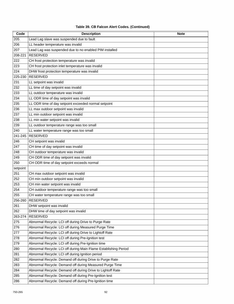
750-265 92
205 Lead Lag slave was suspended due to fault206 LL header temperature was invalid207 Lead Lag was suspended due to no enabled PIM installed208-221 RESERVED222 CH frost protection temperature was invalid223 CH frost protection inlet temperature was invalid224 DHW frost protection temperature was invalid225-230 RESERVED231 LL setpoint was invalid232 LL time of day setpoint was invalid233 LL outdoor temperature was invalid234 LL ODR time of day setpoint was invalid235 LL ODR time of day setpoint exceeded normal setpoint236 LL max outdoor setpoint was invalid237 LL min outdoor setpoint was invalid238 LL min water setpoint was invalid239 LL outdoor temperature range was too small240 LL water temperature range was too small241-245 RESERVED246 CH setpoint was invalid247 CH time of day setpoint was invalid248 CH outdoor temperature was invalid249 CH ODR time of day setpoint was invalid250 CH ODR time of day setpoint exceeds normalsetpoint251 CH max outdoor setpoint was invalid252 CH min outdoor setpoint was invalid253 CH min water setpoint was invalid254 CH outdoor temperature range was too small255 CH water temperature range was too small256-260 RESERVED261 DHW setpoint was invalid262 DHW time of day setpoint was invalid263-274 RESERVED275 Abnormal Recycle: LCI off during Drive to Purge Rate276 Abnormal Recycle: LCI off during Measured Purge Time277 Abnormal Recycle: LCI off during Drive to Lightoff Rate278 Abnormal Recycle: LCI off during Pre-Ignition test279 Abnormal Recycle: LCI off during Pre-Ignition time280 Abnormal Recycle: LCI off during Main Flame Establishing Period281 Abnormal Recycle: LCI off during Ignition period282 Abnormal Recycle: Demand off during Drive to Purge Rate283 Abnormal Recycle: Demand off during Measured Purge Time284 Abnormal Recycle: Demand off during Drive to Lightoff Rate285 Abnormal Recycle: Demand off during Pre-Ignition test286 Abnormal Recycle: Demand off during Pre-Ignition time
Table 39. CB Falcon Alert Codes. (Continued)
Code Description Note

93 750-265
287 Abnormal Recycle: Flame was on during Safe Start check288 Abnormal Recycle: Flame was on during Drive to Purge Rate289 Abnormal Recycle: Flame was on during Measured Purge Time290 Abnormal Recycle: Flame was on during Drive to Lightoff Rate291 Abnormal Recycle: Flame was not on at end of Ignition period292 Abnormal Recycle: Flame was lost during Main Flame Establishing Period293 Abnormal Recycle: Flame was lost early in Run294 Abnormal Recycle: Flame was lost during Run295 Abnormal Recycle: Leakage test failed296 Abnormal Recycle: Interrupted air flow switch was off during Drive to Lightoff Rate297 Abnormal Recycle: Interrupted air flow switch was off during Pre-Ignition test298 Abnormal Recycle: Interrupted air flow switch was off during Pre-Ignition time299 Abnormal Recycle: Interrupted air flow switch was off during Main Flame
Establishing Period300 Abnormal Recycle: Ignition failed due to interrupted air flow switch was off301 Abnormal Recycle: ILK off during Drive to Lightoff Rate302 Abnormal Recycle: ILK off during Pre-Ignition test303 Abnormal Recycle: ILK off during Pre-Ignition time304 Abnormal Recycle: ILK off during Main Flame Establishing Period305 Abnormal Recycle: ILK off during Ignition period306-307 RESERVED308 Run was terminated due to interrupted air flow switch was off309 Not safe to start due to high limit310 Drive to Purge Rate failed due to high limit311 Measured Purge Time failed due to high limit312 Drive to Lightoff Rate failed due to high limit313 Pre-Ignition test failed due to high limit314 Pre-Ignition time failed due to high limit315 Main Flame Establishing Period failed due to high limit316 Ignition failed due to high limit317 Run was terminated due to high limit318 Stuck reset switch319-360 RESERVED361 Internal error: No factory parameters were detected in control362 Internal error: PID iteration frequency was invalid363 Internal error: Demand-Rate interval time was invalid 364 Internal error: Factory calibration parameter for modulation was invalid365 Internal error: CH PID P-scaler was invalid366 Internal error: CH PID I-scaler was invalid367 Internal error: CH PID D-scaler was invalid368 Internal error: DHW PID P-scaler was invalid369 Internal error: DHW PID I-scaler was invalid370 Internal error: DHW PID D-scaler was invalid371 Internal error: Lead Lag master PID P-scaler was invalid372 Internal error: Lead Lag master PID I-scaler was invalid373 Internal error: Lead Lag master PID D-scaler was invalid
Table 39. CB Falcon Alert Codes. (Continued)
Code Description Note

750-265 94
Burner control states are contained in Table 40.
374-466 RESERVED467 Internal error: EEPROM write was attempted before EEPROM was initialized468 Internal error: EEPROM cycle count address was invalid469 Internal error: EEPROM days count address was invalid470 Internal error: EEPROM hours count address was invalid471 Internal error: Lockout record EEPROM index was invalid472 Internal error: Request to write PIM status was invalid473 Internal error: PIM parameter address was invalid474 Internal error: PIM safety parameter address was invalid475 Internal error: Invalid record in lockout history was removed476 Internal error: EEPROM write buffer was full477 Internal error: Data too large was not written to EEPROM478 Internal error: Safety key bit 0 was incorrect479 Internal error: Safety key bit 1 was incorrect480 Internal error: Safety key bit 2 was incorrect481 Internal error: Safety key bit 3 was incorrect482 Internal error: Safety key bit 4 was incorrect483 Internal error: Safety key bit 5 was incorrect484 Internal error: Safety key bit 6 was incorrect485 Internal error: Safety key bit 7 was incorrect486 Internal error: Safety key bit 8 was incorrect487 Internal error: Safety key bit 9 was incorrect488 Internal error: Safety key bit 10 was incorrect489 Internal error: Safety key bit 11 was incorrect490 Internal error: Safety key bit 12 was incorrect491 Internal error: Safety key bit 13 was incorrect492 Internal error: Safety key bit 14 was incorrect493 Internal error: Safety key bit 15 was incorrect494 Internal error: Safety relay timeout495 Internal error: Safety relay commanded off496 Internal error: Unknown safety error occurred497 Internal error: Safety timer was corrupt498 Internal error: Safety timer was expired499 Internal error: Safety timings500 Internal error: Safety shutdown
Table 39. CB Falcon Alert Codes. (Continued)
Code Description Note
Table 40. Burner Control States.
State Name0 Initiate1 Standby Delay2 Standby3 Safe Startup

95 750-265
R7910A pump status codes are contained in Table 41.
4 Prepurge - Drive to Purge Rate5 Prepurge - Measured Purge Time6 Prepurge - Drive to Lightoff Rate7 Preignition Test8 Preignition Time9 Pilot Flame Establishing Period10 Main Flame Establishing Period11 Direct Burner Ignition12 Run13 Postpurge14 Lockout255 Safety Processor Offline
Table 41. Pump Status Codes.
Status Description Note0 Unknown1 Not connected2 Not Lead Lag master3 Pump A Off4 Pump B Off5 Pump C Off6 Pump A Off - Anticondensation (CH demand)7 Pump B Off - Anticondensation (CH demand)8 Pump C Off - Anticondensation (CH demand)9 Pump A Off - Anticondensation (DHW demand)10 Pump B Off - Anticondensation (DHW demand)11 Pump C Off - Anticondensation (DHW demand)12 Pump A Off - Anticondensation (LL demand)13 Pump B Off - Anticondensation (LL demand)14 Pump C Off - Anticondensation (LL demand)15 Pump A On - Slave overrun16 Pump B On - Slave overrun17 Pump C On - Slave overrun18 Pump A On - LL master overrun19 Pump B On - LL master overrun20 Pump C On - LL master overrun21 Pump A Off - Start delay (DHW demand)22 Pump B Off - Start delay (DHW demand)23 Pump C Off - Start delay (DHW demand)24 Pump A On - CH demand25 Pump B On - CH demand26 Pump C On - CH demand27 Pump A On - CH frost protection
Table 40. Burner Control States. (Continued)
State Name

750-265 96
Register WritesWriting to any data register may require an access level password. For those data registers requiring access security a password matching the one contained in the Falcon must be provided before the Falcon allows the data to be changed. A valid password login remains in effect for 10 minutes before another login is required (Falcon timeout for password login).
Two Modbus registers are defined to manage the register data access login:
• (0x00B1) Password• (0x00B2) Register Access Status
The Modbus master writes a password into the Password register to request write access to the data registers. Even though this register is a holding register, and therefore should normally only accept a 16-bit value, it accepts alphanumeric text up to 30 characters in length. Due to this length change, this register must be written individually and not as part of a group register write.
Results of the login are reported by the CB Falcon in the Register Access Status register. If the Modbus master writes the correct installer password, the status register indicates this result and all data with installer access level and below can be
28 Pump B On - CH frost protection29 Pump C On - CH frost protection30 Pump A On - DHW demand31 Pump B On - DHW demand32 Pump C On - DHW demand33 Pump A On - DHW frost protection34 Pump B On - DHW frost protection35 Pump C On - DHW frost protection36 Pump A Off - DHW high limit37 Pump B Off - DHW high limit38 Pump C Off - DHW high limit39 Pump A On - Exercise40 Pump B On - Exercise41 Pump C On - Exercise42 Pump A On - Frost protection43 Pump B On - Frost protection44 Pump C On - Frost protection45 Pump A On - Lead Lag master demand46 Pump B On - Lead Lag master demand47 Pump C On - Lead Lag master demand48 Pump A On - Slave demand49 Pump B On - Slave demand50 Pump C On - Slave demand51 Pump A On - Manual52 Pump B On - Manual53 Pump C On - Manual54 Pump A On - Outlet high limit55 Pump B On - Outlet high limit56 Pump C On - Outlet high limit57 Pump A On - Overrun58 Pump B On - Overrun59 Pump C On - Overrun60 Pump A On - Frost protection overrun61 Pump B On - Frost protection overrun62 Pump C On - Frost protection overrun
Table 41. Pump Status Codes. (Continued)
Status Description Note

97 750-265
changed. If the Modbus master writes the correct OEM password, the status register indicates this result and all data with OEM access level and below can be changed.
03 (0x03) Read Holding RegistersThis function is used to read one or more consecutive data registers in the Falcon. The register address of the first register (see Table 33) in the range is included in the request along with the number of registers to read. Falcon returns a response with the starting register address, the number of bytes returned, followed by the register data contents in register address order (lowest register address first, etc.).
Normally, the number of bytes returned is 2 times the number of registers requested, because each register usually contains a 16-bit value. An exception to this rule is that registers representing variable length text data return the length of the text data, which can exceed 2 bytes.
06 (0x06) Write Single RegisterThis function is used to write data to a single register in theFalcon. The Falcon register address and 16-bit data value to write into the register are sent to the Falcon, and the Falconreturns an acknowledged response.
NOTE: This function (command) cannot be used for variable length text data registers.
16 (0x10) Write Multiple RegistersThis function is used to write data into multiple CB Falcon registers with a single request. The Falcon registers must be located consecutively in the register map because only a base
address is provided. The Modbus master provides the starting register address, the number of registers to write, the total number of bytes, followed by the actual data itself. The R7910A writes the data into each register and acknowledges the completion with a response echoing the number of registers written.
When writing text data to a register representing variable length text, the number of registers should be specified as one and the byte count be the number of bytes in the text data.
17 (0x11) Report Slave IDThis function is used to locate and identify the CB Falcons connected on the Global Modbus network. The Modbus master issues a Report Slave ID request for a specific Modbus address onto the Global Modbus network, and if aCB Falcon exists with the requested Modbus address, it responds to the request. If no Falcon exists, the Modbus master times out and concludes that no Falcon is present with that Modbus address.
Included in the CB Falcon response is the following data to further identify it:
• OS number• Burner name
Format of the Falcon response message is depicted in Table 42.
The OS number (up to 16 characters) and burner name (up to 20 characters) fields are NULL filled text strings. They have a fixed field length so that the boundaries of each field are known. These same Falcon parameters can be obtained with the Read Holding Register function.
The Run Indicator status contains an OFF status when theFalcon is in a lockout or unconfigured state. In any other case the status indicates an ON condition.
NOTE: A slave ID of 0x79 is reserved for all CB Falcon hydronic boiler control models at this time.
Exception CodesThe Modbus exception codes in Table 43 may be given by theFalcon in response to function code requests.
Table 42. Report Slave ID Response
Byte: 0 1 2 3 4 5-20 21-40 41-42Slave
AddressFunction
Code Byte Count Slave ID Run Indicator OS Number Burner Name CRC0x01-0xF0 0x11 0x30 0x79 0x00=OFF
0xFF=ON
Table 43. Modbus Exception Codes.
Code Name Comment0x01 ILLEGAL_FUNCTION llegal function code or action requested0x02 ILLEGAL_DATA_ADDRESS Register address out of bounds

750-265 98
Block Data TransferAn internal Modbus interface exists to transfer blocks of data to/from the CB Falcon. This interface uses a bank of 16-bit holding registers on the Global Modbus port for the transfer. Holding registers are used to keep the Modbus interface simple on the Global Modbus port (limit the number of function codes supported).
Uses for this block data transfer is to move the following type of data:• OEM Parameter PCB• OEM Range PCB• OEM Alert PCB
Data is transferred with 16-bit holding registers defined in Table 44. Data is transferred in blocks up to 32 bytes at a time. Sixteen consecutive holding registers are used as a data buffer to contain the data transferred. The holding register with
the least significant Modbus address, 0x2004, contains the first 2 bytes of data with the first byte in the high order (most significant) bits (16-31), and the second byte in the low order (least significant) bits (0-15). The next 2 bytes of data are placed in Modbus address 0x2005, the next 2 bytes in 0x2006, etc. For example, see Fig. 26.
Fig. 26. Transfer data buffer.
Only 32 bytes can be transferred at a time because the Falconkeeps an internal buffer in application RAM to hold the data while the transfer is occurring.
The procedure to transfer data to the R7910A is:1. Ensure that no transfer is currently in progress by the
Falcon (look at Transfer Status). If so, cancel the trans-fer or wait.
2. Buffer first 2 bytes of data into 16-bit data with first byte in most significant 8 bits and next byte in least signifi-cant 8 bits.
3. Write 16-bit data into first Transfer Data register (address 0x2005).
4. Repeat steps 2 and 3 with next data pair written to next Transfer Data register (address 0x2006, etc.) until all data is written for this block.
5. Write number of bytes in this block to Transfer Size reg-ister.
6. Write destination address for first byte in block into Transfer Base Address register.
7. Write data type into Transfer Type register.
0x03 ILLEGAL_DATA_VALUE Data in register write is invalid for register0x10 READ_MULTIPLE_NOT_OK Exceeded maximum registers allowed in read0x11 ACCESS_FAILURE Invalid password access level for register0x12 LOGIN_FAILURE Unrecognized password given for login
Table 43. Modbus Exception Codes. (Continued)
Code Name Comment
M28109
DATA BUFFER OFFSET
TRANSFER DATA
...2005H
0
2005L
1
2006H
2
2006L
3
2007H
4
2007L
5
Table 44. R7910A Block Data Transfer Register Map.
Address (hex)
Register (dec) Parameter
Read/Write Format Note
2000 8192 Transfer Direction R/W U16 0=Download data into CB Falcon1=Upload data from CB Falcon2=Cancel transfer
2001 8193 Transfer Status R U16 0=No transfer1=Transfer in progress2=Transfer complete3=Transfer failed4=Illegal direction5=Illegal transfer type6=Illegal transfer size7=Illegal transfer address
2002 8194 Transfer Type R/W U16 7=OEM Visibility PCB8=OEM Range PCB9=OEM Alarm PCB
2003 8195 Transfer Base Address R/W U16 Destination or source address for first data transfered
2004 8196 Transfer Size R/W U16 0-322005-2014 8197-8212 Transfer Data R/W U16

99 750-265
8. Write 0 (Download) to Transfer Direction register. This write starts actual download to begin (Transfer Status register should change to transfer in progress).
9. Read Transfer Status register until status indicates transfer is complete (or failed).
10. Repeat steps 2-8 for next block of data.
The procedure to transfer data from the CB Falcon is:1. Ensure that no transfer is currently in progress by the
Falcon (look at Transfer Status). If so, cancel the trans-fer or wait.
2. Write source address for first byte in Falcon into Trans-fer Base Address register.
3. Write total number of bytes to transfer into Transfer Size register (number must be less than 33).
4. Write data type into Transfer Type register.5. Write 1 (Upload) to Transfer Direction register. This
write starts actual upload to begin (Transfer Status reg-ister should change to transfer in progress).
6. Read Transfer Status register until status indicates transfer is complete (or failed).
7. Read Transfer Size register to get the actual number of data bytes transferred by the Falcon. Fewer data bytes may transfer than requested (end of block).
8. Read all Transfer Data registers starting with first one (address 0x2005) until enough have been read to get number of bytes transferred.
PARAMETER CONTROL BLOCK (PCB)Parameter Control Block (PCB) files are used in the Falcon to customize the interface that the user has with the Falcon. Several PCB file types are defined for different customization purposes. The PCB files are maintained outside of the Falconand transferred to the Falcon using the download procedure defined above. The PCB files can be retrieved from the Falcon using the upload procedure defined above.
Each PCB specifies attributes for the public Modbus holding registers. These attributes differ from actually specifying the value of the registers, i.e., configuration parameter settings, but instead define how the register is used in the Falcon installation. These same attributes are uploaded into the Local and System displays when they initially communicate with theCB Falcon.
NOTE: Not all registers in the Modbus register map (see Table 33) are included in the PCB “public” register context. The status and configuration parameter reg-isters from the beginning of the register map up to the end of the Lead Lag configuration group are within the PCB public context. Registers defined above them, e.g., Lockout History, Alert Log, etc., are outside the context of PCB files.
The PCB files are downloaded and uploaded using the Global Modbus block data transfer procedure. A PCB file is transferred in blocks up to 32 bytes at a time. For example, see Fig. 27.
Fig. 27. PCB data transfer.
The PCB data is written to the Transfer Data registers, the number of bytes written is written into the Transfer Size register, and the relative byte offset into the PCB file is written into the Transfer Base Address register. The Falcon adds the byte offset onto an internal base address where it places the PCB file. A download data command is written into the Transfer Direction register to begin the PCB data transfer. Once the transfer is complete the next block in the PCB file is transferred until the complete PCB file is transferred.
TROUBLESHOOTINGTo support the recommended Troubleshooting, the Falcon has an Alert File. Review the Alert history for possible trends that may have been occurring prior to the actual Lockout.
M28110
PCB DATA (BYTE OFFSET)
TRANSFER DATA
...2005H
0
2005L
1
2006H
2
2006L
3
2007H
4
2007L
5
Table 45. Fault Code and Troubleshooting.
Code Description Recommended Troubleshooting of Lockout Codes0 None1 Unconfigured safety data 1. Setup error, return to program mode and recheck.
2. If fault repeats, replace module.

750-265 100
2 Waiting for safety data verification Internal Fault.1. Reset Module.2. If fault repeats, replace module.
3 Internal fault: Hardware fault4 Internal fault: Safety Relay key feedback error5 Internal fault: Unstable power (DCDC) output6 Internal fault: Invalid processor clock7 Internal fault: Safety relay drive error8 Internal fault: Zero crossing not detected9 Internal fault: Flame bias out of range10 Internal fault: Invalid Burner control state11 Internal fault: Invalid Burner control state flag12 Internal fault: Safety relay drive cap short13 Internal fault: PII shorted to ILK Internal Fault.
1. Reset Module. 2. If fault repeats, replace module.
14 Internal fault: HFS shorted to LCI15 Internal fault: Safety Relay Test FB ON16 Internal fault: Safety Relay Test SR OFF17 Internal fault: Safety Relay Test SR not OFF18 Internal fault: Safety Relay Test FB not ON19 RESERVED20 Internal fault: Flame ripple and overflow Internal Fault.
1. Reset Module.2. If fault repeats, replace module.
21 Internal fault: Flame number of sample mismatch22 Internal fault: Flame bias out of range23 Internal fault: Bias changed since heating cycle starts24 Internal fault: Spark voltage stuck low or high25 Internal fault: Spark voltage changed too much during
flame sensing time26 Internal fault: Static flame ripple27 Internal fault: Flame rod shorted to ground detected28 Internal fault: A/D linearity test fails29 Internal fault: Flame bias cannot be set in range30 Internal fault: Flame bias shorted to adjacent pin31 Internal fault: SLO electronics unknown error32-46 RESERVED47 Flame rod to ground leakage 1. Check the flame rod insulator for cracks.
2. Check for potential short of the flame rod to nearby ground or burner surface.3. Check the leadwire for the potential of shorting to ground.4. If steps 1-3 are correct and the fault persists, replace the module.
48 Static flame (not flickering) 1. Check the flame rod position to the flame - should be in outer area 2/3 of the flame.2. Check for potential of other flame simulating conditions.3. Check the leadwire for the potential of being pinched.4. If steps 1-3 are correct and the fault persists, replace the module.
49 24VAC voltage low/high 1. Check the Module and display connections.2. Check the Module power supply and make sure that both frequency, voltage and VA meet the specifications.
Table 45. Fault Code and Troubleshooting. (Continued)
Code Description Recommended Troubleshooting of Lockout Codes

101 750-265
50 Modulation fault Internal sub-system fault.1. Review alert messages for possible trends.2. Correct possible problems.3. If fault persists, replace module.
51 Pump fault52 Motor tachometer fault
53 AC inputs phase reversed 1. Check the Module and display connections.2. Check the Module power supply and make sure that both frequency and voltage meet the specifications.3. On 24Vac applications, assure that J4-10 and J8-2 are connected together.
54-60 RESERVED61 Anti short cycle Will not be a lockout fault. Hold Only.62 Fan speed not proved63 LCI OFF 1. Check wiring and correct any faults.
2. Check Interlocks connected to the LCI to assure proper function.3. Reset and sequence the module; monitor the LCI status.4. If code persists, replace the module.
64 PII OFF 1. Check wiring and correct any faults.2. Check Preignition Interlock switches to assure proper functioning.3. Check the valve operation.4. Reset and sequence the module; monitor the PII status.5. If code persists, replace the module.
65 Interrupted Airflow Switch OFF 1. Check wiring and correct any faults.2. Check airflow switches to assure proper functioning.3. Check the fan/blower operation.4. Reset and sequence the module; monitor the airflow status.5. If code persists, replace the module."
66 Interrupted Airflow Switch ON 1. Check wiring and correct any possible shorts.2. Check airflow switches to assure proper functioning.3. Check the fan/blower operation.4. Reset and sequence the module; monitor the airflow status.5. If code persists, replace the module.
67 ILK OFF 1. Check wiring and correct any possible shorts.2. Check Interlock (ILK) switches to assure proper function.3. Verify voltage through the interlock string to the interlock input with a voltmeter.4. If steps 1-3 are correct and the fault persists, replace the module."
68 ILK ON 1. Check wiring and correct any possible shorts.2. Check Interlock (ILK) switches to assure proper function.3. Verify voltage through the interlock string to the interlock input with a voltmeter.4. If steps 1-3 are correct and the fault persists, replace the module.
69 Pilot test hold 1. Verify Run/Test is changed to Run. 2. Reset Module.3. If fault repeats, replace module.
70 Wait for leakage test completion 1. Internal Fault. Reset Module.2. If fault repeats, replace module.
71-78 RESERVEDOutlet high limit 1. Check wiring and correct any possible errors.
2. Replace the Outlet high limit.3. If previous steps are correct and fault persists, replace the module.
Table 45. Fault Code and Troubleshooting. (Continued)
Code Description Recommended Troubleshooting of Lockout Codes

750-265 102
80 DHW high limit 1. Check wiring and correct any possible errors.2. Replace the DHW high limit.3. If previous steps are correct and fault persists, replace the module.
81 Delta T limit82 Stack limit 1. Check wiring and correct any possible errors.
2. Replace the Stack high limit.3. If previous steps are correct and fault persists, replace the module.
83-90 RESERVED91 Inlet sensor fault 1. Check wiring and correct any possible errors.
2. Replace the Inlet sensor.3. If previous steps are correct and fault persists, replace the module.
92 Outlet sensor fault 1. Check wiring and correct any possible errors. 2. Replace the Outlet sensor.3. If previous steps are correct and fault persists, replace the module.
93 DHW sensor fault 1. Check wiring and correct any possible errors. 2. Replace the DHW sensor.3. If previous steps are correct and fault persists, replace the module.
94 Header sensor fault 1. Check wiring and correct any possible errors.2. Replace the header sensor.3. If previous steps are correct and fault persists, replace the module.
95 Stack sensor fault 1. Check wiring and correct any possible errors.2. Replace the stack sensor.3. If previous steps are correct and fault persists, replace the module.
96 Outdoor sensor fault 1. Check wiring and correct any possible errors.2. Replace the outdoor sensor.3. If previous steps are correct and fault persists, replace the module.
97-104 RESERVED105 Flame detected out of sequence 1. Check that flame is not present in the combustion
chamber. Correct any errors.2. Make sure that the flame detector is wired to the correct terminal.3. Make sure the F & G wires are protected from stray noise pickup.4. Reset and sequence the module, if code reappears, replace the flame detector.5. Reset and sequence the module, if code reappears, replace the module.
106 Flame lost in MFEP 1. Inspect the main fuel valve (s) and connection (s).2. Make sure that the fuel pressure is high enough to supply fuel to the combustion chamber.3. Make sure the flame detector is positioned to obtain the required flame signal strength.4. Reset the module and recycle.5. If fault persists, replace the module.
107 Flame lost early in run 1. Inspect the main fuel valve (s) and connection (s).2. Make sure that the fuel pressure is high enough to supply fuel to the combustion chamber.3. Make sure the flame detector is positioned to obtain the required flame signal strength.4. Reset the module and recycle.5. If fault persists, replace the module.
Table 45. Fault Code and Troubleshooting. (Continued)
Code Description Recommended Troubleshooting of Lockout Codes

103 750-265
108 Flame lost in run 1. Inspect the main fuel valve (s) and connection (s).2. Make sure that the fuel pressure is high enough to supply fuel to the combustion chamber.3. Make sure the flame detector is positioned to obtain the required flame signal strength.4. Reset the module and recycle.5. If fault persists, replace the module.
109 Ignition failed 1. Check pilot valve (Main Valve for DSI) wiring and operation - correct any errors.2. Check the fuel supply.3. Check furl pressure and repeat turndown tests.4. Check ignition transformer electrode, flame detector, flame detector siting or flame rod position.5. If steps 1 through 4 are correct and the fault persists, replace the module.
110 Ignition failure occurred Will not be a lockout fault. Hold Only.111 RESERVED112 Pilot test flame timeout Interrupted Pilot or DSI application and flame lost when
system in “test” mode.1. Reset the module to restart.
113 Flame circuit timeout Will not be a lockout fault. Hold Only.114-121 RESERVED122 Lightoff rate proving failed 1. Check wiring and correct any potential wiring errors.
2. Check VFDs ability to change speeds.3. Change the VFD.4. If the fault persists, replace the module.
123 Purge rate proving failed 1. Check wiring and correct any potential wiring errors.2. Check VFDs ability to change speeds.3. Change the VFD.4. If the fault persists, replace the module.
124 High fire switch OFF 1. Check wiring and correct any potential wiring errors.2. Check High Fire Switch to assure proper function. 3. Manually drive the motor to the High Fire position and adjust the HF switch while in this position and verify voltage through the switch to the HFS input with a voltmeter.4. If steps 1-3 are correct and the fault persists, replace the module.
125 High fire switch stuck ON 1. Check wiring and correct any potential wiring errors.2. Check High Fire Switch to assure proper function. 3. Manually drive the motor to the High Fire position and adjust the HF switch while in this position and verify voltage through the switch to the HFS input with a voltmeter.4. If steps 1-3 are correct and the fault persists, replace the module.
126 Low fire switch OFF 1. Check wiring and correct any potential wiring errors.2. Check Low Fire Switch to assure proper function. 3. Manually drive the motor to the High Fire position and adjust the LF switch while in this position and verify voltage through the switch to the LFS input with a voltmeter.4. If steps 1-3 are correct and the fault persists, replace the module.
127 Low fire switch stuck ON 1. Check wiring and correct any potential wiring errors.2. Check Low Fire Switch to assure proper function. 3. Manually drive the motor to the High Fire position and adjust the LF switch while in this position and verify voltage through the switch to the LFS input with a voltmeter.4. If steps 1-3 are correct and the fault persists, replace the module.
128-135 RESERVED
Table 45. Fault Code and Troubleshooting. (Continued)
Code Description Recommended Troubleshooting of Lockout Codes

750-265 104
136 Interrupted Airflow Switch failed to close 1. Check wiring and correct any possible wiring errors.2. Check Interrupted Airflow switch(es) to assure proper function. 3. Verify voltage through the airflow switch to the IAS input with a voltmeter.4. If steps 1-3 are correct and the fault persists, replace the module.
137 ILK failed to close 1. Check wiring and correct any possible shorts.2. Check Interlock (ILK) switches to assure proper function. 3. Verify voltage through the interlock string to the interlock input with a voltmeter.4. If steps 1-3 are correct and the fault persists, replace the module.
138-148 RESERVED149 Flame detected150 High fire switch 1. Check wiring and correct any potential wiring errors.
2. Check High Fire Switch to assure proper function. 3. Manually drive the motor to the High Fire position and adjust the HF switch while in this position and verify voltage through the switch to the HFS input with a voltmeter.4. If steps 1-3 are correct and the fault persists, replace the module.
151 High fire switch ON 1. Check wiring and correct any potential wiring errors.2. Check High Fire Switch to assure proper function. 3. Manually drive the motor to the High Fire position and adjust the HF switch while in this position and verify voltage through the switch to the HFS input with a voltmeter.4. If steps 1-3 are correct and the fault persists, replace the module.
152 Combustion pressure ON153 Standby purge fan switch154 Hold purge fan switch155 Combustion pressure/flame156 Combustion pressure ON157 High fire switch 1. Check wiring and correct any potential wiring errors.
2. Check High Fire Switch to assure proper function. 3. Manually drive the motor to the High Fire position and adjust the HF switch while in this position and verify voltage through the switch to the HFS input with a voltmeter.4. If steps 1-3 are correct and the fault persists, replace the module.
158 Flame detected 1. Check that flame is not present in the combustion chamber. Correct any errors.2. Make sure that the flame detector is wired to the correct terminal. 3. Make sure the F & G wires are protected from stray noise pickup.4. Reset and sequence the module, if code reappears, replace the flame detector.5. Reset and sequence the module, if code reappears, replace the module.
159 Main flame ignition 1. Inspect the main fuel valve (s) and connection (s). 2. Make sure that the fuel pressure is high enough to supply fuel to the combustion chamber.3. Make sure the flame detector is positioned to obtain the required flame signal strength.4. Reset the module, if fault persists, replace the module.
Table 45. Fault Code and Troubleshooting. (Continued)
Code Description Recommended Troubleshooting of Lockout Codes

105 750-265
160 Main valve OFF 1. Check Main Valve terminal wiring and correct any errors.2. Reset and sequence the module. If fault persist, replace the module.
161 Ignition OFF 1. Check Ignition terminal wiring and correct any errors.2. Reset and sequence the module. If fault persist, replace the module.
162 Main valve ON 1. Check Main Valve terminal wiring and correct any errors.2. Reset and sequence the module. If fault persist, replace the module.
163 Pilot valve ON 1. Check Pilot Valve terminal wiring and correct any errors.2. Reset and sequence the module. If fault persist, replace the module.
164 Ignition ON 1. Check Ignition terminal wiring and correct any errors.2. Reset and sequence the module. If fault persist, replace the module.
165 Combustion pressure 1. Check wiring and correct any errors.2. Inspect the Combustion Pressure Switch to make sure it is working correctly.3. Reset and sequence the module.4. During Standby and Purge, measure the voltage across the switch. Supply voltage should be present. If not, the Combustion Pressure Switch is defective and needs replacing.5. If the fault persists, replace the relay module.
166 No flame167 Purge fan switch ON168 Block intake 1. Check wiring and correct any errors.
2. Inspect the Block Intake Switch to make sure it is working correctly.3. Reset and sequence the module.4. During Standby and Purge, measure the voltage across the switch. Supply voltage should be present. If not, the Block Intake Switch is defective and needs replacing.5. If the fault persists, replace the relay module.
169 Purge fan switch OFF170 Combustion pressure/flame171 Flame detected172 Main relay feedback incorrect Internal Fault.
1. Reset Module.2. If fault repeats, replace module.
173 Pilot relay feedback incorrect Internal Fault.1. Reset Module.2. If fault repeats, replace module.
174 Safety relay feedback incorrect Internal Fault.1. Reset Module.2. If fault repeats, replace module.
175 Safety relay open Internal Fault.1. Reset Module.2. If fault repeats, replace module.
176-183 RESERVED
Table 45. Fault Code and Troubleshooting. (Continued)
Code Description Recommended Troubleshooting of Lockout Codes

750-265 106
184 Invalid BLOWER/HSI output setting 1. Return to program mode and recheck.2. If fault repeats, verify electrical grounding.3. If fault repeats, replace module.
185 Invalid Delta T limit enable setting186 Invalid Delta T limit response setting187 Invalid DHW high limit enable setting188 Invalid DHW high limit response setting189 Invalid Flame sensor type setting190 Invalid interrupted air switch enable setting191 Invalid interrupted air switch start check enable setting192 Invalid Igniter on during setting193 Invalid Ignite failure delay setting194 Invalid Ignite failure response setting195 Invalid Ignite failure retries setting196 Invalid Ignition source setting197 Invalid Interlock open response setting198 Invalid Interlock start check setting 1. Return to program mode and recheck.
2. If fault repeats, verify electrical grounding.3. If fault repeats, replace module.
199 Invalid LCI enable setting200 Invalid lightoff rate setting201 Invalid Lightoff rate proving setting202 Invalid Main Flame Establishing Period time setting203 Invalid MFEP flame failure response setting204 Invalid NTC sensor type setting205 Invalid Outlet high limit response setting206 Invalid Pilot Flame Establishing Period setting207 Invalid PII enable setting208 Invalid pilot test hold setting209 Invalid Pilot type setting210 Invalid Postpurge time setting211 Invalid Power up with lockout setting212 Invalid Preignition time setting213 Invalid Prepurge rate setting214 Invalid Prepurge time setting215 Invalid Purge rate proving setting216 Invalid Run flame failure response setting217 Invalid Run stabilization time setting218 Invalid Stack limit enable setting219 Invalid Stack limit response setting220 Unconfigured Delta T limit setpoint setting221 Unconfigured DHW high limit setpoint setting222 Unconfigured Outlet high limit setpoint setting223 Unconfigured Stack limit setpoint setting224-255 RESERVED
Table 45. Fault Code and Troubleshooting. (Continued)
Code Description Recommended Troubleshooting of Lockout Codes

APPENDIX B - CB FALCON DISPLAY / OPERATOR INTERFACE


USER GUIDE
65-0296-01
CB Manual Part Number 750-241
833-3577 CB-Falcon SystemOperator Interface
APPLICATIONThe 833-3577 is a microprocessor-based touch-screen display module that provides an operator interface for monitoring and configuring parameters in the 833-3639 CB-Falcon system.
The 833-3577 is flush mounted into a panel cutout (8-1/8 in. W x 5-7/8 in. H). Wiring connections to the 833-3577 are through a removable 9-pin wiring header.
FEATURES• Individual and multiple boiler status, configuration,
history, diagnostics, and trend analysis.• Allows configuration and monitoring of the 833-3639
system.• Allows monitoring of the 833-3639 burner control
sequence, flame signal, diagnostics, historical files, and faults.
• Allows switching view between multiple boilers.• Allows for lead/lag commissioning (future
enhancement).• Locates attached boilers.• Allows boiler naming.• System trend analysis.• Color 3.5 in. x 4.625 in. (5.7 in. diagonal) user interface
display.• Touch screen.• Three communication ports:
• Two RS-485 Modbus™ ports• One Ethernet port
• LED indicators:• Power• Modbus™ (COM 1) communication
• Flush mounting.• Touch screen disable for screen cleaning.• 12 Vdc power supply (included).• Screen saver.• Contrast control.• Volume control.• Real-time data trending analysis.• Graphic user interface.
ContentsPreface ............................................................................ 2Installation Instructions .................................................... 3Wiring ............................................................................... 3Quick Setup ..................................................................... 4Starting the Display .......................................................... 4Configuration ................................................................... 15Monitoring ........................................................................ 28833-3639 Diagnostics ...................................................... 40Display Setup and Diagnostics ........................................ 42Advanced Setup .............................................................. 48Table 42 Configuration Parameters .................................. 43Table 43, 44 Other Tables................................................. 52

833-3577 CB-FALCON SYSTEM OPERATOR INTERFACE
65-0296—01 2 750-241
PREFACEThis User Guide is intended to provide a general overview of the 833-3577 Operator Interface. The general overview goes to page 13 and the actual configuration begins on page 15.
It is intended to guide you through the features and operation of the 833-3577 as you interface with the 833-3639 CB-Falcon control and establish the Parameter points of the system.
Note that this sheet (like the 833-3650 CB-Falcon) shows all parameters. The actual product may have parameters made invisible or Read Only by the OEM as they may not apply for their product.
Use the Product Data Sheet for the 833-3639 CB-Falcon (form 750-241) as a guide and explanation of the parameters that are being programmed.
SPECIFICATIONSElectrical Ratings:833-3577:
+12 Vdc input, maximum of 500 mA current drain.
Included Power Supply:Inputs: 85 to 264 Vac, 47-63 Hz; 120 to 370 VdcOutput: 12 Vdc; 0 to 2.1 A.Power: 25W
Operating Temperature: 32°F to 122°F (0°C to 50°C)
Storage/Shipping Temperature: -40°F to 158° (-40°C to 70°C).
Humidity:85% maximum relative humidity.
Approvals:FCC Part 15, Class A Digital DeviceUnderwritter Laboratories, Inc. (UL) (cUL) Component
Recognized (for non-continuous operation): File Num-ber MH20613 (MCCZ)
Canada: ICES-003
Dimensions: See Fig. 1.
Replacement Parts• 9-pin connector—50020034-001• Power Supply—Manufactured by MeanWell
Fig. 1. 833-3577 dimensions in in. (mm).
NOTE: This equipment has been tested and found to comply with the limits for a Class A digital device, pursuant to part 15 of the FCC Rules. These limits are designed to provide reasonable protection against harmful interference when the equipment is operated in a commercial environment. This equipment generates, uses and can radiate radio frequency energy and, if not installed and used in accordance with the instruction manual, may cause harmful interference to radio communications. Operation of this equipment in a residential area is likely to cause harmful interference in which case the user will be required to correct the interference at his own expense.
This Class A digital apparatus complies with Canadian ICES-003.Cet Appareil numérique de la classe A est conforme à la norme NMB-003 du Canada.
6-21/32(169)
9-13/32 (239)
8-1/8 (206)
5-55/64(149)
1-9/16 (40)
1-1/32 (26)
M28163PANEL HOLE CUTOUT SIZE 8-1/8 IN. WIDE X 5-7/8 IN. HIGH.1
1
5-7/8(149) 1

833-3577 CB-FALCON SYSTEM OPERATOR INTERFACE
750-241 3 65-0296—01
SAFETY FEATURESThe 833-3577 contains software that incorporates many features that are designed to guide you safely through the commissioning process. Safety, however, is your responsibility.
Read all documentation carefully and respond appropriately to all error messages.
WARNINGExplosion Hazard.Improper configuration can cause fuel buildup and explosion.Improper user operation may result in PROPERTY LOSS, PHYSICAL INJURY or DEATH.
The 833-3577 System Display used to change parameters, must be attempted by only experienced and/or licensed burner/boiler operators and mechanics.
INSTALLATION INSTRUCTIONSMounting the 833-3577 and Power SupplyThe 833-3577 can be mounted on the door panel of an electrical enclosure.
1. Select the location on the door panel to mount the unit; note that the device will extend into the enclosure at least one inch past the mounting surface.
2. Provide an opening in the panel door 8-1/8 in. wide by 5-7/8 in. high.
3. Place the 833-3577 in the opening and use it as a tem-plate to mark the location of the four mounting screw holes. Remove the device.
4. Using the pilot holes as guides, drill 1/4 in. holes through the door panel.
5. Place the 833-3577 in the opening, aligning the mount-ing holes in the device with the drilled holes in the panel.
6. Secure the 833-3577 to the panel with four #6-32 screws and nuts provided.
7. Select a location inside the enclosure for mounting the power supply.
8. Using the power supply as a template, mark the loca-tions of two mounting holes in the enclosure.
9. Remove the power supply.10. Drill 1/4 in. holes through the panel at the marked loca-
tions and secure the power supply with the two #6-32 screws and nuts provided.
11. Remove the 9-pin connector plug from the back of the 833-3577.
12. Wire the connector to the power supply and the RS-485 cables using the wiring diagram in Fig. 2.
13. Ensure the 9-pin connector plug is aligned with the header pin when inserting the 9-pin connector plug back onto the 833-3577. Secure firmly.
WIRINGThe 833-3577 must be appropriately wired for both power and communications. An external 12V power supply (provided) with an appropriate power rating is connected to pins 1 and 2 to power the device.
Communication is done over two RS-485 busses:
• COM1 connected directly to the 833-3639 Modbus (MB1) or Modbus (MB2).
See Fig. 2 for connector terminals. 833-3577 wiring connections are listed in Table 1. See Fig. 3 for wiring.
Fig. 2. 833-3577 connector terminals.
An RJ45 jack can optionally be wired with a 10 base-T Ethernet cable for Internet access.
Table 1. 9-pin Connector Terminals
Pin # Function1 12V input2 12V input3 Common (Power, COM 1)4 COM 1 (b) to Global or Local Modbus™5 COM 1 (a) to Global or Local Modbus™6 Not used7 Not used8 Not used9 Not used
1 2 3 4 5 6 7 8 9
M28164
CO
MM
ON
(c)
CO
M1
(b)
CO
M1
(a)
N/C
N/C
N/C
N/C
+12V

833-3577 CB-FALCON SYSTEM OPERATOR INTERFACE
65-0296—01 4 750-241
Fig. 3. Wiring diagram.
QUICK SETUP1. Make sure the 833-3577 9-pin connector is properly
aligned and pressed firmly in place.2. Make sure the 9-pin connector is connected securely to
the 833-3639 controller RS-485 communication port.
WARNINGElectrical Shock Hazard.Can cause severe injury, death or equipment damage.Line voltage is present at the 120 Vac power supply.
3. Make sure the +12 Vdc power supply (supplied with the 833-3577) is connected securely to the 120 Vac power source.
STARTING THE DISPLAY
Power-up ValidationThe Home page will appear and the POWER LED will be blinking when the device is properly powered. Select the Setup button to adjust the contrast as desired.
If the screen is dim, check pin 1 wiring connections.
NOTE: An Advanced Startup screen displays for five sec-onds after power-up before the Home page displays. This screen allows the user to upgrade the software in the 833-3577 System Display (see “Preface” on page 2) and should normally be bypassed.
Communication ValidationThree LEDs exist for I/O traffic, one for the Ethernet port and two for the Modbus™ ports.
1. Make sure the LEDs are blinking.2. If the LEDs are not blinking:
a. Make sure the proper connections have been made between the 833-3577 Modbus™ Com 1 Port and the first 833-3639 device in the Modbus™ global net-work.
b. See “Wiring” on page 3 for proper wiring of the 833-3577 9-pin Header Connections.
Home PageMake sure a screen similar to Fig. 4 appears after the 833-3577 is completely powered up.
On 833-3577 System applications, each 833-3639 in the hydronic system is represented on the Home page by an icon and name. Pressing the icon allows the user to zoom in on that boiler and see specific details about it. These details are provided on a new page, which can include additional buttons that display additional detail and operation information, which itself leads to other pages. The pages are traversed in a tree structure method, as shown in Fig. 5.
M28200
21 4 5 6 7 8 93
+12 (B) (A) N/CGND (C)
+12 N/C (A) (B)
LOCAL DISPLAYCOM1 COM2
L1
L2
120
VAC
V ADJ
V+
N
L
V-DC OUT
(COMMON GND)
12 DC OUT +
EARTHGROUND
120VAC (L1)
NEUTRAL (L2)
MEAN WELL S-25-12
DO NOT CONNECT THE LOCAL DISPLAY TO TERMINALS 1 2 3.THIS WILL RENDER THE DISPLAY INOPERABLE.
POWER SUPPLY
WIRING KEY
LOW VOLTAGE
DATA
LINE VOLTAGE
2 3CBACBA 1
HYDRONIC CONTROL
J3MB1 ECOMMB2
1
1

833-3577 CB-FALCON SYSTEM OPERATOR INTERFACE
750-241 5 65-0296—01
The 833-3639 icon button will appear in one of four colors indicating the boiler status.
• Blue: Normal operation• Red: Lockout condition• Gray: Standby mode (burner switch off)• Gray and crossed out: 833-3639 communication error
(disconnected or powered off)
Up to 8 833-3639s can be displayed on the System Home page. The name of each boiler is displayed next to the 833-3639 button. When Lead Lag is enabled, the system header temperature and firing rate are displayed for each 833-3639. When the burner is in standby or not firing the firing rate is not displayed.
NOTE: The boiler name may be cut off on the Home page when all 833-3639s are present for the hydronic sys-tem.
The Home page also includes a System Analysis button that allows the user to view status information on a system-wide (that is, multiple boiler) basis. The user can choose which status information to compare from the 833-3639s in the system.
Pressing the Setup button on the Home page displays miscellaneous 833-3577 setup and diagnostic functions (See page 48 for options).
Fig. 4. 833-3577 Home page (Boiler 1 in normal operation.)
Page NavigationThe 833-3577 System Display presents information and options in a paged manner. Pages are displayed in a tree structure in which the user navigates up and down to arrive at the desired Function (see Fig. 5). The page descriptions are provided below so that you can understand the purpose of each and view the selections, parameters, and information that is available or required on each.
Most pages have a Home button in the top-left corner of
the screen and a Back button in the top-right corner ofthe screen. The Home button returns the user to the Home page and terminates any operation in progress. The Back button returns the user to the previous page.
Two other icons may be noticed near the boiler name.
A bell will be displayed if the system is in Lockout that reset will be required.
A padlock will be shown on screens that a password is needed to change the parameter. An unlocked padlock indicates the password has been entered to change the parameter(either the installer or OEM), depending on the security level entered.

833-3577 CB-FALCON SYSTEM OPERATOR INTERFACE
65-0296—01 6 750-241
Fig. 5. Page flow.
KeyboardSome pages request user entry of characters. When this type of input is required, a keyboard page appears, as shown in Fig. 6. The text box at the top of the screen displays the current (or default) setting of the user input. The user can add to this text, clear it, or change it.
Fig. 6. Keyboard.
The Shift key on the left side of the screen shifts between upper- and lowercase characters. Pressing the Shift key toggles the keyboard from one mode to the other (continuous pressing of the Shift button is not required). The OK button should be pressed when the user is done entering the text input. The Cancel button on the bottom of the screen allows the user to ignore any text changes that have been made and
keep the original text value. Pressing the OK or Cancel buttons returns the user to the page displayed prior to the keyboard page.
Status PageA status (summary) page (Fig. 7) is displayed when an 833-3639 is selected on the Home page. The status page displays the current condition of the 833-3639 and displays some of the more important configuration settings.
The boiler name associated with the 833-3639 is displayed in the title on the status page.
NOTE: When 833-3639 has no boiler name defined, 833-3577 displays the 833-3639 Modbus address to identify the boiler.
The initial status page displayed for the 833-3639 contains summary status information as shown in Fig. 7. Any status information not applicable for the installation is grayed/blanked out on the screen.
Buttons on this screen include:• Configure: used to configure the 833-3639 (see
“Configuration Page” for more details).• Operation: used to perform daily/frequent functions with
the 833-3639, such as setpoint adjustment, etc. (See “Operation Page” on page 12 for more details.)
• Diagnostic: used to view 833-3639 diagnostic information (see “Diagnostic Page” on page 13 for more details).
• Details: used to view 833-3639 detail status information (see “Monitoring” on page 28).
• History: used to view 833-3639 history (see “History Page” on page 11 for more details).
• ?: used to expand the pump status information.• Modulation: used to toggle between three different status
displays: pump, modulation, and setpoint.
HOMEPAGE
CONFIGURATIONMENU
SAFETYVERIFICATION
CONFIGURATIONGROUP
CONFIGURATIONGROUP
CONFIGURATIONGROUP
STATUSSUMMARY
PASSWORD
BUTTON FLOW
KEY
BACK BUTTON FLOW
DIAGNOSTICS
M28201
STATUSDETAIL
HISTORY

833-3577 CB-FALCON SYSTEM OPERATOR INTERFACE
750-241 7 65-0296—01
Fig. 7. 833-3639 summary status page.
Configuration PageThe configuration page allows the user to view and set parameters that define how the 833-3639 functions in the hydronic heating system.
Configuration parameters for any 833-3639 connected in the Global Modbus™ network can be accessed from the 833-3577. Press the 833-3639’s button on the Home page to access the Status page. Pressing the Configure button on the 833-3639 status page starts a configuration session with the 833-3639.
The configuration page contains a menu of parameters grouped into functional areas that the user selects for configuration (see Fig. 8). See Table 42 on page 43 for all parameters available for configuration. If some parameters are not visible, they have been made invisible by the OEM.
Fig. 8. Configuration menu page.
No specific order for configuring the 833-3639 is required. All parameters are enabled for editing, though some may not be applicable (e.g., a configuration parameter may disable an 833-3639 feature). Selecting a parameter group from the menu displays parameters exclusively applicable for the functional group on the page (see Fig. 9). These parameters can be edited, and when the user is finished, control returns back to the configuration menu page.
Fig. 9. Sample configuration page.
Each parameter is displayed in its group. If there are more parameters than will fit on the screen, a vertical scroll bar allows the user to scroll up and down to view all parameters. The parameter name is displayed on the left and the current setting is displayed in the text box on the right.
Configuration PasswordAny user can view the configuration parameters (default mode). No access-level password is required to view the parameters.
To change a parameter, a valid configuration password for that parameter’s level must be entered by the user before the parameter can be changed (if required). The password need only be entered once while the user remains on the configuration pages. Leaving the configuration pages ends the scope of the password entry.
The user is notified that a new password is needed upon the first attempt to change a parameter (or until a password is entered successfully)—see Fig. 10. The user can continue viewing the configuration parameters regardless of whether a password is entered successfully.

833-3577 CB-FALCON SYSTEM OPERATOR INTERFACE
65-0296—01 8 750-241
Fig. 10. Login required.
The 833-3639 also maintains a password timeout that limits the scope of the password entry. Once a password is successfully entered the 833-3639 starts an internal timer that expires after 10 minutes of inactivity. After the timer expires, the user is required to re-enter a password before a parameter can be changed.
The user is not required to enter a configuration password for a parameter that has a lower access level than the access level achieved by an earlier password entry for any configuration group (as long as the user stays in the configuration pages). The user only needs to enter a password once until a parameter that has a higher access level is selected.
The user enters the password from a keyboard as shown in Fig. 11. After the password is entered, the OK button is selected. The Cancel button aborts the password login.
Fig. 11. 833-3639 login.
Three levels of write access to 833-3639 parameters are permitted. Each access level has defined rights when interfacing with configuration and status parameters in the 833-3639.
• End user: the lowest access rights (no password login). The end user can, in most cases, only read or view 833-3639 parameters. In some instances the end user can change 833-3639 parameters, e.g., change the CH setpoint.
• Installer: the next highest level. The installer can read all 833-3639 parameters and change most 833-3639 parameters. This access level is used to customize the 833-3639 for a particular installation.
• OEM: the highest access level. The OEM can read and change all 833-3639 parameters, as well as change sensor limits and burner control safety parameters.
Different passwords exist in the 833-3639 for each access level. The end user level requires no password, but the installer and OEM levels have unique passwords defined for them. The 833-3577 validates all password entry attempts with the 833-3639, but doesn’t conduct the validation itself. 833-3639 has sole responsibility to accept a password entry.
The 833-3577 gets information from each 833-3639 about the access level settings for the status and configuration parameters.
The installer and OEM passwords can be changed in the 833-3639 after logging in with the current password. When the password is changed at the 833-3577 it is saved in the 833-3639 and effective for all future logins.
NOTE: Each 833-3639 in a multi-boiler configuration has its own set of installer and OEM passwords. To avoid user confusion the passwords should be changed to the same setting in all 833-3639s, but there is no requirement to do so.
WARNINGExplosion Hazard.Improper configuration can cause fuel buildup and explosion.Improper user operation may result in PROPERTY LOSS, PHYSICAL INJURY or DEATH.
The 833-3577 System Display used to change parameters, must be attempted by only experienced and/or licensed burner/boiler operators and mechanics.
Change Parameter SettingsChange parameter settings by selecting the parameter on the page. A dialog box displays for the parameter with controls allowing the user to change the value (see Fig. 12). After changing the setting to a new value, press the OK button. Pressing the Cancel button leaves the parameter unchanged.
The changed setting is reflected on the screen and sent to the 833-3639 when the OK button is pressed.

833-3577 CB-FALCON SYSTEM OPERATOR INTERFACE
750-241 9 65-0296—01
Fig. 12. Change configuration parameter page.
For safety configuration parameters an additional verification step is required to commit the changes.
Safety parameters are grouped into blocks that include only safety parameters, not a mixture of safety data and non-safety data. All parameters within the safety group undergo a verification process. A safety parameter group is identified on the 833-3577 to indicate when the configuration parameters are safety-related. Each safety parameter group is verified one at a time until all have been verified. See Fig. 13.
Fig. 13. Safety verification.
Safety parameters can be viewed the same way non-safety parameters can be viewed. If the user makes no attempt to change a safety parameter, the user isn’t required to enter safety verification mode.
A verification step is required for each safety parameter block that is changed. The verification steps do not have to be completed immediately; the user can traverse between parameter groups before the verifications are done. A Verify
button is enabled that allows the user to conduct verification sessions (the Verify button in Fig. 8 is not yet enabled because the user hasn’t logged in).
NOTE: When the user proceeds with the safety parameter configuration the 833-3577 requests that the 833-3639 enter this mode. In this mode the 833-3639 unlocks the safety parameters in this group and marks them unusable. Failure to complete the entire safety configuration procedure leaves the 833-3639 in an un-runnable state.
All safety configuration parameters in the group should have the same access level. If this condition isn’t so, the user is asked to enter another password when a higher access level is needed.
Successful entry of the 833-3639 into safety verification mode is displayed and the lock icon will appear "unlocked" on the page with the first safety block displayed. The user may begin to change safety parameters (or any other parameters) at that time. See Fig. 14. If the 833-3639 is already in an un-configured state, then this warning doesn’t appear. All parameters that need it should be changed during the edit stage.
Fig. 14. Edit safety data.
If the user terminates the safety configuration session after it has started (in the Edit or Confirm stages), the 833-3639 is left in an unconfigured (unrunnable) state.
The user can terminate the session by pressing the Menu button or by attempting to leave the Verification page with the Home or Back buttons (top-left and -right screen corners, respectively). The user is warned that leaving the session at this point leaves the 833-3639 in an unrunnable state and confirms whether the user still wants to do so.
The settings of all parameters in each safety block must be confirmed to commit them in the 833-3639.
When the user is done changing safety parameters, pressing the Confirm button begins the confirmation stage. The settings for all safety parameters in each changed block are presented and confirmed by the user (see Fig. 15).

833-3577 CB-FALCON SYSTEM OPERATOR INTERFACE
65-0296—01 10 750-241
Fig. 15. Safety parameter confirmation.
Press the Yes button to confirm each safety parameter block. If the user selects the No button, the safety parameter block remains unconfirmed and the Configuration menu page is displayed. The 833-3639 remains in an unconfigured state in this case.
After all safety parameter blocks have been confirmed, the user is asked to press and hold the Reset button on the 833-3639 to complete the safety configuration session (see Fig. 16).
Fig. 16. Safety parameter reset.
When the Reset button is pressed and held for 3 seconds the confirmed safety parameters are committed in the 833-3639. The above Reset dialog box automatically closes when this step is completed if not already OK’ed by the user. Control returns to the page where the Confirm button was pressed.
If the user doesn’t perform this step, the 833-3639 remains in a locked state until the user resolves the unconfirmed safety parameters. Leaving the configuration page and returning later indicates that the 833-3639 is in this mode.
Fault/Alarm HandlingEach 833-3639 reports a fault code when a lockout condition occurs for one of the following annunciations:
• Burner control• Lockout• Lead/Lag control
A less serious alarm condition may also occur that is treated as warning instead of a fault. Active fault codes for each annunciation and a warning code can be reported by each 833-3639.
Any new fault code detected in an 833-3639 is indicated as a lockout condition at the 833-3577. The notification method used depends on the page that is displayed. On the Home page the button for the 833-3639 with the fault turns red. On an 833-3639 status page the History button turns red. On all other pages and when the user is looking at a different 833-3639, a notification dialog box displays indicating which 833-3639 just locked out.
The lockout history can be displayed for each 833-3639. The state information about each lockout is displayed along with the date/time that the lockout occurred (see Table 2). See “System Time” on page 50 for additional information on setting the display clock.
An alert log can be displayed for each 833-3639. A description of the alert is displayed along with the time when the alert occurred (see Table 3).
Table 2. 833-3639 Lockout History.
Data CommentLockout time Set by 833-3577Fault code Unique code defining which
lockout occurred.Annunciator first out First interlock in limit string
results in a shutdown.Description Fault descriptionBurner Lockout/Hold Source/reason for lockout/
holdBurner control stateSequence time Burner control state timer at
time of faultCycle Burner control cycleRun Hours Burner control hoursI/O All digital I/O status at time of
faultAnnunciator 1-8 states All annunciator I/O status at
time of faultFault data Fault dependent data
Table 3. 833-3639 Alert Log.
Data CommentAlert time Set by 833-3577

833-3577 CB-FALCON SYSTEM OPERATOR INTERFACE
750-241 11 65-0296—01
History PageThe History button serves not only as a button, but also displays 833-3639 lockouts, holds, and alerts as they occur. The History button can be selected at any time, regardless of which type of information is displayed, to view history information. Pressing the History button displays a dialog box (see Fig. 17) that allows the user to select the type of history to view. The user can also silence an audible alarm generated by the 833-3639 during a lockout or alert condition.
This History dialog box provides an exploded view of the status information displayed in the History button (the font is larger). One of the four buttons (OK, Lockouts, Alerts, or Silence) can be selected. If none of these buttons are selected the dialog box closes after 30 seconds.
Fig. 17. 833-3639 history—exploded view.
Two types of historical data can be displayed on the history page: lockout history and alert log.
The entire 15 fault history is displayed in a scrollable list with the most recent fault displayed first followed by the next most recent fault. Summary information is displayed for each fault entry, including the burner cycle count, fault code, and fault
number with description. Detailed information for a specific fault entry that also includes burner control sequence state, burner run-time hours, annunciation status, etc., is viewed by selecting (touching the History line) the lockout entry in the list (see “Fault/Alarm Handling” on page 10 for details).
Fig. 18. 833-3639 lockout history.
The date and time that each fault occurred is displayed in the lockout history. The lockout timestamp displays in both the lockout summary and detail information.
The 833-3639 has no system time; the timestamp is assigned by the 833-3577 when it learns of the lockout from the 833-3639. When the 833-3577 first extracts the lockout history from the 833-3639 (during 833-3639 data synchronization), no timestamps are assigned since the times that the lockouts occurred are unknown. All new lockouts that occur after the extraction are assigned timestamps.
NOTE: The system time can be set in the 833-3577 to ensure that correct timestamps are given to the 833-3639 lockouts. See “System Time” on page 50 for additional information on setting the display clock.
The Clear Lockout button allows the user to acknowledge and clear the lockout when in lockout state.
The user can toggle between displaying the 833-3639 lockout history and alert log. The Alerts or Lockouts button on the bottom of the pages toggles the history displayed to the type indicated by the button.
Alert code Unique code defining which fault occurred.
Description Alert description
Table 3. 833-3639 Alert Log. (Continued)
Data Comment

833-3577 CB-FALCON SYSTEM OPERATOR INTERFACE
65-0296—01 12 750-241
Fig. 19. 833-3639 alert log.
To see additional detail about a lockout or alert, select the lockout/alert in the list to display the lockout detail or alert detail pages, as shown in Fig. 20 and 21.
Fig. 20. 833-3639 lockout detail.
Fig. 21. 833-3639 alert detail.
Operation PageThe operation page displays the 833-3639 running operation, including setpoint and firing rate values. From this page the user can change setpoints, manually control the boiler’s firing rate, manually turn pumps on, view annunciation information, and switch between heating loops (Central Heat and Domestic Hot Water), as shown in Fig. 22. If a password is required to change any of the settings on this page, the user can press the Login button to enter the password.
Annunciation information is shown in Fig. 23 and Fig. 24.
Fig. 22. 833-3639 operation page.

833-3577 CB-FALCON SYSTEM OPERATOR INTERFACE
750-241 13 65-0296—01
Fig. 23. Programmable annunciation.
Fig. 24. Fixed annunciation.
Diagnostic PageThe diagnostic page displays analog and digital I/O status of the 833-3639. A snapshot of the diagnostic status is displayed and updated once per second as it changes in the 833-3639. See “833-3639 Diagnostics” on page 40 for more information about this status.
The digital I/O data is displayed as LEDs that are either on (green) or off (red) (see Fig. 25). Not all digital I/O can be displayed at the same time on the page, so a horizontal scroll bar is used to move the view left and right to show all digitalI/O data.
Fig. 25. Diagnostic page (digital I/O).
833-3639 analog I/O can also be viewed on the 833-3577. A snapshot of the diagnostic status is displayed and updated as it changes in the 833-3639.
The analog I/O data is displayed as bar charts with the I/O level represented in the I/O range (see Fig. 26). Analog I/O that is not enabled for the installation displays a blank I/O level. Not all analog I/O can be displayed at the same time on the page, so a horizontal scroll bar is used to move the view left and right to show all analog I/O status.
Fig. 26. Diagnostics page (analog I/O).
A Diagnostic Tests button allows the user to conduct different diagnostics with the 833-3639 (see “Diagnostics Tests” on page 42).
Trend Analysis PageTrend analysis of 833-3639 status data can be viewed on the 833-3577. A graph displays a historical view of 833-3639 status data over varying time periods.

833-3577 CB-FALCON SYSTEM OPERATOR INTERFACE
65-0296—01 14 750-241
A 2-dimensional graph with status data values shown on the Y axis over time specified on the X axis is displayed. Status for the most recent time is represented on the left side of the graph with older status running towards the right side of the graph.
Fig. 27. Trend analysis page.

833-3577 CB-FALCON SYSTEM OPERATOR INTERFACE
750-241 15 65-0296—01
CONFIGURATIONEach 833-3639 can be configured individually from the 833-3577. The 833-3639 configuration is grouped into the following functional groups:
• System Identification & Access• CH - Central Heat Configuration• Outdoor Reset Configuration• DHW - Domestic Hot Water Configuration• Modulation Configuration• Pump Configuration• Statistics Configuration• High Limits• Stack Limit• Other Limits• Anti-condensation Configuration• Frost Protection Configuration• Annunciation Configuration• Burner Control Interlocks• Burner Control Timings & Rates• Burner Control Ignition• Burner Control Flame Failure• System Configuration• Fan Configuration• Lead Lag Configuration
Most of this configuration is performed by either the contractor/installer or the OEM. Each functional group is displayed on the Configuration menu page.
Parameters in functional groups that are not applicable for the installation can be ignored. In some cases, features in a functional group are disabled by default and are enabled when needed for the installation.
System ConfigurationThe 833-3577 has some functions related to general configuration of all the 833-3639s in the end user installation.
The user can search for new 833-3639s installed in the Global Modbus network from the 833-3577. Pressing the Refresh button invokes a search procedure (see Fig. 28). A new 833-3639 is identified by “Unknown” status next to its name in the boiler system list (see Fig. 29). “Unknown” indicates that configuration data has not been retrieved from the 833-3639 yet.
Fig. 28. System refresh.
Fig. 29. System configuration page.
833-3639s no longer connected to the Global Modbus network are indicated to the user after the search procedure has concluded. Each missing 833-3639 can be permanently removed from system consideration by the user, as shown in Fig. 30.
Fig. 30. Delete missing 833-3639.

833-3577 CB-FALCON SYSTEM OPERATOR INTERFACE
65-0296—01 16 750-241
Once all 833-3639s are located the 833-3639s must be synchronized with the 833-3577 before they can be displayed. New 833-3639s are not displayed on the Home page until this synchronization (see below) is performed.
System SynchronizationThe user can manually synchronize configuration data from the 833-3639 at any time.
A new 833-3639 isn’t visible on the Home page until configuration and status data is gathered from it. This collection procedure takes several minutes. The 833-3639 is marked as “Unknown” when no configuration information exists. Normally, 833-3639 configuration data collection only needs to be performed when the 833-3639 is initially installed. However, a resynchronization is necessary after the 833-3577 is reset. See Fig. 31.
The user selects an 833-3639 from the boiler system list and then presses the Synchronize button to begin synchronization with the 833-3639. See Fig. 31.
Fig. 31. System synchronization.
Status of the synchronization is reflected in the dialog box. The synchronization can be aborted by selecting the Cancel button. Table 4 displays System Identification and Access parameters.
833-3639 Configuration ParametersThe following pages list the configuration parameters available for each 833-3639 installed on the system.
WARNINGExplosion Hazard.Improper configuration can cause fuel buildup and explosion.Improper user operation may result in PROPERTY LOSS, PHYSICAL INJURY or DEATH.
The 833-3577 System Display used to change parameters, must be attempted by only experienced and/or licensed burner/boiler operators and mechanics.
Fig. 32. System identification and access configuration.
When the burner name is changed, the name is saved in the 833-3639 and displayed in the title of all pages that zoom into the 833-3639.
Default parameter settings for installer and OEM passwords are “sola” and “solaoem,” respectively. These passwords most likely have been changed by the OEM.
OEM ID gives the OEM an option to display a brand name other than CB-Falcon on this configuration page. Additional information displayed on this page is listed in Table 5.
Table 4. System Identification and Access Parameters.
Parameter CommentBoiler Name Name to identify boiler (up to 20
characters)Installation Notes regarding installation (up to 20
characters)Installer password Change installer password settingOEM password Change OEM password settingOEM ID OEM name to associate with boiler
(up to 20 characters)

833-3577 CB-FALCON SYSTEM OPERATOR INTERFACE
750-241 17 65-0296—01
Central Heat ParametersTable 7 displays Central Heat configuration parameters.
Fig. 33. Central Heat configuration.
Outdoor Reset ParametersTable 7 displays Outdoor Reset configuration parameters.
Fig. 34. Outdoor reset configuration.
Table 5. System Identification Information.
Status CommentProduct Type Type of product that the burner isOS Number Model number associated with burnerSoftware Version Version of software running in 833-
3639Date Code Date when 833-3639 was assembledApplication Revision Version of application data in 833-
3639Safety Revision Revision of safety data in 833-3639
Table 6. Central Heat Configuration Parameters.
Parameter CommentCH enable Disable or Enable Central Heating
LoopCH demand source Sensor for Central Heat demand:
Sensor onlySensor & STAT terminalSensor & Remote StatLCI & Sensor
CH sensor Which sensor to use for Central Heat modulationOutlet sensorHeader sensor
CH setpoint Setpoint for normal Central Heat modulation:-40 °C - 130 °C (-40 °F - 266 °F)
CH time of day setpoint
Setpoint when Time Of Day switch is on. -40 °C - 130 °C (-40 °F - 266 °F)
CH off hysteresis Differential above setpoint when boiler is turned off.0 °C - 130 °C (32 °F - 266 °F)
CH on hysteresis Differential from setpoint when boiler is turned on. 0 °C - 130 °C (32 °F - 266 °F)
CH hysteresis step time
Time between hysteresis step changes: 0-600 seconds (0=Disable hysteresis stepping)
CH outdoor reset EnabledDisabled
CH P-gain Time between hysteresis step changes: 0-100
CH I-gain Time between hysteresis step changes: 0-100
CH D-gain Time between hysteresis step changes: 0-100
Table 7. Outdoor Reset Configuration Parameters.
Parameter CommentCH maximum outdoor temperature
-40 °C - 130 °C (-40 °F - 266 °F)
CH minimum outdoor temperature
-40 °C - 130 °C (-40 °F - 266 °F)
CH minimum water temperature
-40 °C - 130 °C (-40 °F - 266 °F)
CH outdoor boost time
0-600 seconds
CH outdoor boost maximum setpoint
-40 °C - 130 °C (-40 °F - 266 °F)
Lead Lag maximum outdoor temperature
-40 °C - 130 °C (-40 °F - 266 °F)
Lead Lag minimum outdoor temperature
-40 °C - 130 °C (-40 °F - 266 °F)
Table 6. Central Heat Configuration Parameters.
Parameter Comment

833-3577 CB-FALCON SYSTEM OPERATOR INTERFACE
65-0296—01 18 750-241
Domestic Hot Water (DHW) Configuration ParametersTable 8 displays Domestic Hot Water (DHW) configuration parameters.
Fig. 35. Domestic Hot Water (DHW) configuration.
Lead Lag minimum water temperature
-40 °C - 130 °C (-40 °F - 266 °F)
Lead Lag outdoor boost time
0-600 seconds
Lead Lag outdoor boost maximum setpoint
-40 °C - 130 °C (-40 °F - 266 °F)
Table 7. Outdoor Reset Configuration Parameters.
Parameter Comment Table 8. Domestic Hot Water (DHW)Configuration Parameters.
Parameter CommentDHW enable Disable or Enable Domestic Hot
Water LoopDHW demand source Sensor for Central Heat demand:
DHW sensor only,DHW sensor & Remote Stat,DHW switch & inlet sensor, orDHW switch & outlet sensor
DHW priority vs CH Which system has priority:Central Heat over Domestic Hot Water, or Domestic Hot Water over Central Heat
DHW priority vs LL Which system has priority:Lead Lag over Domestic Hot Water,Domestic Hot Water over Lead Lag
DHW priority time No DHW priority time (0), or DHW priority time (seconds)
DHW setpoint -40 °C - 130 °C (-40 °F - 266 °F)DHW time of day setpoint
Setpoint when Time Of Day switch is on. -40 °C - 130 °C (-40 °F - 266 °F)
DHW off hysteresis Differential above setpoint when boiler is turned off. -40 °C - 130 °C (-40 °F - 266 °F)
DHW on hysteresis Differential from setpoint when boiler is turned on. -40 °C - 130 °C (-40 °F - 266 °F)
DHW hysteresis step time
Time between hysteresis step changes: 0-600 seconds (0=Disable hysteresis stepping)
DHW P-gain Time between hysteresis step changes: 0-100
DHW I-gain Time between hysteresis step changes: 0-100
DHW D-gain Time between hysteresis step changes: 0-100

833-3577 CB-FALCON SYSTEM OPERATOR INTERFACE
750-241 19 65-0296—01
Modulation Configuration ParametersTable 9 displays Modulation configuration parameters.
Fig. 36. Modulation configuration.
Pump Configuration ParametersTable 10 displays Pump configuration parameters.
Fig. 37. Pump configuration.
Table 9. ModulationConfiguration Parameters.
Parameter CommentCH maximum modulation rate
RPM or %
DHW maximum modulation rate
RPM or %
Minimum modulation rate
RPM or %
CH forced rate time 0-600 secondsCH forced rate RPM or %DHW forced rate time 0-600 secondsDHW forced rate RPM or %CH slow start enable Enabled
DisabledDHW slow start enable
EnabledDisabled
Slow start degrees -40 °C - 130 °C (-40 °F - 266 °F)Slow Start Ramp RPM /minute or %/minute0-10/4-20 mAOutput hysteresis
Table 10. Pump Configuration Parameters.
Parameter CommentAuxiliary pump control
AutoOn
Auxiliary pump is on when
CH pump is ONDHW pump is ONCH or DHW pump is ONSlave command
Auxiliary pump output Pump APump BPump CNone
Boiler pump control AutoOn
Boiler pump output Pump APump BPump CNone
Boiler pump overrun time
0-600 seconds0 = Not configured
CH pump control AutoOn
CH pump output Pump APump BPump CNone
CH pump overrun time
0-600 seconds0 = Not configured
CH pump frost overrun time
0-600 seconds0 = Not configured
DHW pump control AutoOn
DHW pump output Pump APump BPump CNone

833-3577 CB-FALCON SYSTEM OPERATOR INTERFACE
65-0296—01 20 750-241
Statistics Configuration ParametersTable 11 displays Statistics configuration parameters.
Fig. 38. Statistics configuration.
High Limit Configuration ParametersTable 12 displays outlet high limit configuration parameters.
Fig. 39. High Limits configuration.
DHW pump overrun time
0-600 seconds0 = Not configured
DHW pump frost overrun time
0-600 seconds0 = Not configured
DHW pump start delay
0-600 seconds0 = Not configured
System pump control AutoOn
System pump output Pump APump BPump CNone
System pump overrun time
0-600 seconds0 = Not configured
System exercise interval
Days
Pump exercise time 0-600 seconds0 = Not configured
Table 11. Statistics Configuration Parameters.
Parameter CommentAuxiliary pump cycles 0-999,999Boiler pump cycles 0-999,999
Table 10. Pump Configuration Parameters. (Continued)
Parameter CommentBurner cycles 0-999,999Burner run time HoursCH pump cycles 0-999,999DHW pump cycles 0-999,999System pump cycles 0-999,999
Table 12. High Limit Configuration Parameters.
Parameter CommentDHW high limit Enabled
DisabledDHW high limit response
Recycle & holdLockout
DHW high limit setpoint
-40 °C - 130 °C (-40 °F - 266 °F)
Outlet high limit response
Recycle & holdLockout
Outlet high limit setpoint
-40 °C - 130 °C (-40 °F - 266 °F)
Table 11. Statistics Configuration Parameters.
Parameter Comment

833-3577 CB-FALCON SYSTEM OPERATOR INTERFACE
750-241 21 65-0296—01
Stack Limit Configuration ParametersTable 13 displays stack limit configuration parameters.
Fig. 40. Stack Limit configuration.
Other Limit Configuration ParametersTable 14 displays other limit parameters.
Fig. 41. Other Limit configuration.
Table 13. Stack Limit Configuration Parameters.
Parameter CommentStack limit Enabled
DisabledStack limit delay 0-600 secondsStack limit response Lockout
Recycle & delayStack limit setpoint -40 °C - 130 °C (-40 °F - 266 °F)
Table 14. Other Limit Configuration Parameters.
Parameter CommentDelta-T limit enable Enabled
DisabledDelta-T limit delay 0-600 secondsDelta-T limit response
Recycle & delayLockout
Delta-T limit degrees -40 °C - 130 °C (-40 °F - 266 °F)Outlet T-rise limit enable‘
EnabledDisabled
Outlet T-rise degrees -40 °C - 130 °C (-40 °F - 266 °F)Outlet T-rise delay 0-600 seconds

833-3577 CB-FALCON SYSTEM OPERATOR INTERFACE
65-0296—01 22 750-241
Anti-Condensation Configuration ParametersTable 15 displays anti-condensation parameters.
Fig. 42. Anti-condensation configuration.
Frost Protection ParametersTable 16 displays frost protection parameters.
Fig. 43. Frost Protection configuration.
Table 15. Anti-Condensation Configuration Parameters.
Parameter CommentCH anticondensation enable
EnabledDisabled
CH anticondensation pump
Normal (no change)CH pump forced off
CH anticondensation setpoint
-40 °C - 130 °C (-40 °F - 266 °F)
DHW anticondensation enable
EnabledDisabled
DHW anticondensation pump
Normal (no change)DHW pump forced off
DHW anticondensation setpoint
-40 °C - 130 °C (-40 °F - 266 °F)
Anticondensation priority
Is anticondensation more important than (0=No, 1=Yes)?
Bit map:15-5=Reserved (always 0)4=Outlet high limit3=Forced rate2=Slow start1=Delta-T limit0=Stack limit
Table 16. Frost Protection Configuration Parameters.
Parameter CommentCH frost protection enable
EnabledDisabled
DHW frost protection enable
EnabledDisabled
Outdoor frost protection setpoint
-40 °C - 130 °C (-40 °F - 266 °F) (applicable for CH only)

833-3577 CB-FALCON SYSTEM OPERATOR INTERFACE
750-241 23 65-0296—01
Annunciation Configuration ParametersTable 17 displays annunciation configuration parameters.
Fig. 44. Annunciation configuration.
Safety Configuration ParametersTable 18 through 21 display safety parameters.
Fig. 45. Burner Control Interlocks control.
Table 17. Annunciation Configuration Parameters.
Parameter CommentAnnunciation enable Enabled
DisabledAnnunciator mode Fixed
ProgrammableAnnunciator (1–8) location
UnusedPIILCIILKOther
Annunciator (1–8) short name
Up to 3 characters
Annunciator (1–8) name
Up to 20 characters
PII, LCI, ILK short name
Up to 3 characters
PII, LCI, ILK name Up to 20 characters
Table 18. Burner ControlInterlocks Configuration.
Parameter CommentPII enable Enabled
DisabledLCI enable Enabled
DisabledInterrupted air switch (IAS) enable
Enable during purge and ignitionDisabled
IAS start check enable
EnabledDisabled
Interlock (ILK) start check enable
No ILK checkILK check
ILK/IAS open response
RecycleLockout
Purge rate proving Fan SpeedHigh Fire SwitchNone
Lightoff rate proving Fan SpeedLow Fire SwitchNone

833-3577 CB-FALCON SYSTEM OPERATOR INTERFACE
65-0296—01 24 750-241
Fig. 46. Burner Control Safety Timing configuration.
Fig. 47. Burner Control Ignition configuration.
Fig. 48. Burner Control Flame Failure configuration.
Table 19. Burner Control Safety Timing Configuration.
Parameter CommentPrepurge rate RPM or %Prepurge time 0-600 seconds
0 = Not configuredRun stabilization time 0-600 seconds
0 = Not configuredPre-ignition time 0-600 seconds
0xFFFF=Not configuredPostpurge rate RPM or %Postpurge time 0-600 seconds
0 = Not configured
Table 20. Burner Control Ignition Configuration.
Parameter CommentPilot test hold ON
OFFIgnition source Hot Surface Igniter
External ignitionInternal ignition
Pilot type Direct burner ignitionIntermittentInterrupted
Lightoff rate %Preignition time 0-600 seconds
0 = Not configuredPilot Flame Establishing Period
15 secs10 secs4 secs
Igniter on during 1st half of PFEPPilot Flame Establishing Period
Main Flame Establishing Period
15 secs10 secs5 secs
Flame Threshold μA/V
Table 21. Burner Control Flame Failure Configuration.
Parameter CommentIgnite failure delay 0-600 seconds
0 = Not configuredIgnite failure response
LockoutContinuous recycleRecycle & holdRecycle & lockout
Ignite failure retries 3 or 5MFEP flame failure response
RecycleLockout
Run flame failure response
RecycleLockout

833-3577 CB-FALCON SYSTEM OPERATOR INTERFACE
750-241 25 65-0296—01
Safety Parameter VerificationWhen any of the safety configuration parameters are changed, the safety parameter verification procedure must be performed before the 833-3639A will resume burner control. The 833-3639A enters a lockout state, if not already in one, and remains locked out until this verification procedure is performed.
Safety parameter verification lockout occurs when safety parameter setting is changed. See Fig. 49.
Fig. 49. Safety verification lockout.
The user must log in before verification can be completed, as shown in Fig. 50.
Fig. 50. Safety verification login.
After successful login, the user presses the Begin button to start safety parameter verification. See Fig. 51.
Fig. 51. Begin safety verification.
The first group of safety configuration parameters that needs verification is displayed. The user is asked to confirm that the settings are correct, as shown in Fig. 52.
Fig. 52. Confirm safety parameter settings.

833-3577 CB-FALCON SYSTEM OPERATOR INTERFACE
65-0296—01 26 750-241
After the first safety parameter group has been confirmed by the user (by pressing the Yes button), the next safety parameter group waits for verification as shown in Fig. 53.
Fig. 53. Safety parameter settings confirmed; next group waiting for confirmation.
The user has 30 secs to confirm each safety configuration group’s settings. If the user takes too long to confirm the settings, an error message is displayed, as shown in Fig. 54.
Fig. 54. Confirmation timed out.
After all safety parameter groups have been verified, the user must press the Reset button on the 833-3639A within 30 seconds to confirm the correct device. See Fig. 55.
Fig. 55. Reset 833-3639A.
When the user has pressed Reset button on the 833-3639A, completing verification procedure, a Verification Complete screen is displayed, as shown in as shown in Fig. 56.
Fig. 56. Safety parameter configuration complete.

833-3577 CB-FALCON SYSTEM OPERATOR INTERFACE
750-241 27 65-0296—01
If for some reason the user does not press the Reset button on the 833-3639A within 30 seconds, the configuration is cancelled, as shown in Fig. 57.
Fig. 57. 833-3639A reset timed out.
Individual 833-3639 Configuration ParametersTable 22 displays system configuration parameters for individual 833-3639s.
Fig. 58. System configuration.
Fan ParametersTable 23 displays fan parameters.
Fig. 59. Fan configuration.
Table 22. 833-3639 SystemConfiguration Parameters.
Parameter CommentNTC sensor type 10k dual safety
12k single non-safetyFlame sensor type UV power tube
Flame rodNone
Modulation output 4-20mA0-10VFan PWM
Temperature Units FahrenheitCelsius
Anti short cycle time 0-600 seconds0 = Not configured
Alarm silence time 0-600 minutes0 = Not configured
Power up with lockout
Clear lockoutDo NOT clear lockout
Table 23. Fan Configuration Parameters.
Parameter CommentAbsolute maximum fan speed
RPM
Absolute minimum fan speed
RPM
Fan gain down 0-65535Minimum duty cycle 1-100%Pulses per revolution 1-10PWM frequency 1000
200030004000
Slow down ramp 0-7000RPM/secSpeed up ramp 0-7000RPM/sec
Table 22. 833-3639 SystemConfiguration Parameters. (Continued)
Parameter Comment
833-3577 CB-FALCON SYSTEM OPERATOR INTERFACE
65-0296—01 28 750-241
MONITORINGMonitoring of the hydronic system is accomplished through the system status and detail status pages. The detail status page is shown below.
Fig. 60. 833-3639 detail status page.
Status information on the detail status page is organized into groups and displayed on the page one group at a time. The user moves from one group to another using the left and right arrow buttons.
Status data on the detail status page is displayed in a menu for the group that is currently displayed. If more status items exist in the group than will fit on the screen, a vertical scroll bar allows the user to see all status data. If the user selects a line of status data in the menu, it will “explode” in bigger, more easily readable text, as show in Fig. 61. Additional information about Status data and groups that are displayed are provided in the 833-3639 Status section of this document.
Fig. 61. 833-3639 “exploded” detail status.
The 833-3577 can direct the 833-3639 to start or stop its burner control function. The user is required to enter the installer password, if not already entered, before the burner control can be stopped or started.
The user can view 833-3639 trend analysis from this page (see “Trend Analysis Page” on page 13 for more details).
833-3639 StatusData in Table 24–38 are displayed on the 833-3639 status page. A complete list of Status tables can be found in Table 43 on page 52.
The CH status data shown in Table 24 displays first when the CH heating loop is selected on the Home page.
Fig. 62. CH Status menu (top).
Table 24. CH Status.
Data Comment Demand source CH, DHW, Lead Lag, or Frost
Protection (parameter that has current priority)
CH status Disabled, Normal, Suspended Outlet sensor state None, Monitor, Open, Short, Alarm
(None=no outlet sensor) Outlet temperature Outlet temperature (same as bar
graph) Modulation setpoint CH setpoint based on TOD setting.
Outlet high limit Yes or No CH pump On or Off (CH pump switch). CH pump overrun time
Count down of CH pump overrun

833-3577 CB-FALCON SYSTEM OPERATOR INTERFACE
750-241 29 65-0296—01
Fig. 63. CH Status menu (middle).
Fig. 64. CH Status menu (bottom).
The status data in Table 25 displays first when the DHW heating loop is selected on the Home page. Scrolling through the status groups eventually shows both.
1 DHW demand request status is reported by the 833-3639. Expected 833-3639 implementation depends on DHW demand source. When DHW demand source is Switch, 833-3639 reports digital status (no matter what has current demand priority). When DHW demand source is Sensor, 833-3639 reports “Yes”; when DHW temperature is between DHW setpoint - hysteresis On and DHW setpoint + hysteresis Off, otherwise it reports “No.”
The bar graph displayed for the CH control loop is the outlet sensor temperature; for the DHW control loop it is the DHW sensor temperature. When no analog DHW sensor is installed (digital switch instead), the inlet sensor temperature is displayed.
Fig. 65. DHW Status menu (top).
Table 25. DHW Status.
Data Comment Demand source CH, DHW, Lead Lag, or Frost
Protection (parameter that has current priority)
DHW status Disabled, Normal, Suspended DHW demand request
Yes or No1.
DHW temperature DHW temperature (NTC 10K analog) or N/A (digital switch)
DHW sensor state None, Monitor, Blocked, Lockout, Open, Short, Alarm (None=no DHW sensor)
Modulation setpoint DHW setpoint based on TOD setting. DHW high limit Yes or No (DHW limit switch status) DHW pump On or Off (DHW pump switch). DHW pump overrun time
Count down of DHW pump overrun

833-3577 CB-FALCON SYSTEM OPERATOR INTERFACE
65-0296—01 30 750-241
Fig. 66. DHW Status menu (middle).
Fig. 67. DHW Status menu (bottom).
The Burner Control status page will display the status data shown in Table 26.
The bar graph displayed for this status is the outlet sensor temperature.
Fig. 68. Burner Control Status menu (top).
Fig. 69. Burner Control Status menu (middle).
Table 26. Burner Control Status.
Data Comment Burner control status Disabled, Lockout, Hold,
Unconfigured safety data, Normal Sequence state Burner control sequence state Fault Current fault code when active fault Last warning Last reported warning code Alarm reason Reason for last 833-3639 alarm:
None, Lockout, or Other Annunciator first out First annunciator input related to
lockout
Burner Lockout/Hold Display source for lockout/hold status Delay time Running display of delay time when
burner control in delay state. Firing rate % or RPM. Adjustable when firing rate
control set to Manual. Firing rate control Auto or Manual Flame signal Flame signal strength Pilot test hold On or Off (only applicable when pilot
type is interrupted)
Table 26. Burner Control Status. (Continued)
Data Comment

833-3577 CB-FALCON SYSTEM OPERATOR INTERFACE
750-241 31 65-0296—01
Fig. 70. Burner Control Status menu (bottom).
Burner control can be turned on and off in the 833-3639 by the user.
Table 28 displays the status page data for 833-3639 demand and modulation.
The bar graph displayed for this status is the outlet sensor temperature.
Fig. 71. Demand and Modulation Status menu (top).
Fig. 72. Demand and Modulation Status menu (bottom).
Table 28 displays the status page data for 833-3639 inlet temperature.
The bar graph displayed for this status is the inlet sensor temperature.
Table 27. Demand and Modulation Status.
Data Comment Demand source CH, DHW, Lead Lag, or Frost
Protection (parameter that has current priority)
Firing rate % or RPM. Adjustable when firing rate control set to Manual.
Demand rate % or RPM.Rate limit % or RPM, or NoneLimited rate % or RPMRate override Disable or Enable Rate OverrideOverride rate % or RPM
Table 28. Inlet High Limit Status.
Data Comment Inlet temperature Inlet sensor temperature (same as bar
graph)Inlet sensor state None, Monitor, Blocked, Lockout,
Open, Short, or Alarm (None=no inlet sensor)

833-3577 CB-FALCON SYSTEM OPERATOR INTERFACE
65-0296—01 32 750-241
Fig. 73. Inlet High Limit Status menu.
Table 29 displays the status page data for the fan in the 833-3639.
The bar graph displayed for this status is the fan speed.
Fig. 74. 833-3639 Fan Status menu.
Table 29 displays the status page data for the pump in the 833-3639.
The pump status page is displayed in Fig. 75.
Fig. 75. 833-3639 Pump Status menu (top).
Table 29. 833-3639 Fan Status.
Data Comment Fan speed Current fan speed (% or RPM) Air flow Yes or No. Air Flow switch or feedback
status
Table 30. 833-3639 Pump Status.
Data Comment Auxiliary pump On or Off (Auxiliary pump switch)Auxiliary pump idle days
Days
Boiler pump On or Off (Boiler pump switch)Boiler pump idle days DaysBoiler pump overrun time
Count down of Boiler pump overrun
CH pump On or Off (CH pump switch)CH pump idle days DaysCH pump overrun time
Count down of CH pump overrun
DHW pump On or Off (DHW pump switch)DHW pump idle days DaysDHW start delay SecondsDHW pump overrun time
Count down of DHW pump overrun

833-3577 CB-FALCON SYSTEM OPERATOR INTERFACE
750-241 33 65-0296—01
Fig. 76. 833-3639 Pump Status menu (middle).
Fig. 77. 833-3639 Pump Status menu (bottom).
The status data shown in Table 31 is displayed for flame detection in the 833-3639.
The bar graph displayed for this status is the flame signal.
Fig. 78. Flame Detection Status menu.
NOTE: This same status is also displayed for burner control status. A separate status group is defined, however, to provide a bar graph of the flame signal and to automatically launch a flame signal trend analysis.
Table 32 displays the statistics status page data for the 833-3639.
The bar graph displayed for this status is the outlet sensor temperature.
Table 31. Flame Detection Status.
Data Comment Flame signal V (voltage) Pilot test hold On or Off (only applicable when pilot
type is interrupted)
Table 32. 833-3639 Statistics Status.
Data Comment Auxiliary pump cycles Number of cyclesBoiler pump cycles Number of cyclesBurner cycles Number of cyclesBurner run time Duration of run timeCH pump cycles Number of cyclesController cycles Number of cyclesController run time Duration of run timeDHW pump cycles Number of cyclesSystem pump cycles Number of cycles

833-3577 CB-FALCON SYSTEM OPERATOR INTERFACE
65-0296—01 34 750-241
Fig. 79. 833-3639 Statistics Status menu (top).
Fig. 80. 833-3639 Statistics Status menu (bottom).
Table 33 shows the status page data for 833-3639 Stack Limit.
The bar graph displayed for this status is the stack sensor temperature.
Fig. 81. Stack Limit Status menu.
Table 34 shows the status page data when Delta T Limit is configured for the 833-3639.
The bar graph displayed for this status is the outlet sensor temperature.
Fig. 82. Delta T Limit Status menu.
Table 35 shows the status page data when Outdoor reset is configured for either CH or Lead Lag in the 833-3639.
Table 33. Stack Limit Status.
Data Comment Stack temperature Stack temperature (same as bar
graph) Stack sensor state None, Monitor, Recycle, and Delay,
Lockout, Open, Short, Alarm (None=no stack temp sensor)
Stack limit Yes or No
Table 34. Delta T Limit Status.
Data Comment Delta T limit Yes or No Outlet temperature Outlet sensor temperature Inlet temperature Inlet sensor temperature Vessel flow Outlet temp - Inlet temp Firing rate % or RPM

833-3577 CB-FALCON SYSTEM OPERATOR INTERFACE
750-241 35 65-0296—01
The bar graph displayed for this status is the outdoor sensor temperature.
Fig. 83. Outdoor Reset Status menu.
Table 36 shows the status page data when Frost protection is configured for the 833-3639.
The bar graph displayed for this status is the outlet sensor temperature. Trend analysis displayed for this status is outlet sensor, outdoor sensor, CH frost, and outdoor frost temperatures.
Fig. 84. CH Frost Protection Status menu (top).
Fig. 85. CH Frost Protection Status menu (bottom).
Table 37 shows the status page data when Frost protection and DHW heating are configured for the 833-3639.
The bar graph displayed for this status is the DHW sensor temperature. Trend analysis displayed for this status is DHW sensor, outdoor sensor, and DHW frost temperatures.
Table 35. Outdoor Status.
Data Comment Outdoor temperature Outdoor temperature (same as bar
graph) Outdoor sensor state None, Monitor, Open, Short, Alarm
(None=no outdoor temp sensor)
Table 36. CH Frost Protection Status.
Data Comment Frost protection state None, Monitor, Active (frost protection
occurring) Burner control state Burner control sequence state Firing rate Outlet temperature Outlet sensor temperature CH frost temperature CH temperature when frost protection
becomes active Outdoor temperature Outdoor temperature (when enabled) Outdoor frost temperature
Outdoor temperature when frost protection becomes active
CH pump On or Off (CH pump switch) CH pump override Pump override time countdown (poll
every second?)
Table 37. DHW Frost Protection Status.
Data Comment Frost protection state None, Monitor, Active (frost protection
occurring) Burner control state Burner control sequence state Firing rate DHW temperature DHW sensor temperature DHW frost temperature
DHW temperature when frost protection becomes active

833-3577 CB-FALCON SYSTEM OPERATOR INTERFACE
65-0296—01 36 750-241
Fig. 86. DHW Frost Protection Status menu (top).
Fig. 87. DHW Frost Protection Status menu (bottom).
Table 36 shows the statistics that are displayed for the 833-3639.
The bar graph and trend analysis displayed for this status is the outlet sensor temperature. See Fig. 60.
Table 38 shows the status page data when Lead Lag is configured for the 833-3639.
The bar graph displayed for this status is the header sensor temperature.
Fig. 88. Lead Lag Status menu (top).
Data Comment Burner cycles Burner cycle count Burner hours Burner runtime hours CH pump cycles CH pump cycle count (transition from
off to on) DHW pump cycles DHW pump cycle count (transition
from off to on) System pump cycles System pump cycle count (transition
from off to on)Calls for heat
Table 38. Lead Lag Status.
Data Comment Type Slave, Master, or Master & Slave Lead Lag status Disabled, Normal, Suspended Slave status Valid at slave only. Slave mcrate (master control rate)
% load of entire system. Set by master.
System pump On or Off (System pump switch). System pump overrun time
Count down of System pump overrun
Staging demand to modulation delay
Seconds (applicable at master only).
Header temperature Get from master 833-3639 (same as bar graph)
Header sensor state None, Monitor, Open, Short, Alarm (None=no header temp sensor)
Lead Lag setpoint Get from master 833-3639.

833-3577 CB-FALCON SYSTEM OPERATOR INTERFACE
750-241 37 65-0296—01
Fig. 89. Lead Lag Status menu (middle).
Fig. 90. Lead Lag Status menu (bottom).
Trend Analysis PageTrend analysis of 833-3639 status data can be viewed on the 833-3577. A graph displays a historical view of 833-3639 status data over varying time periods.
A 2-dimensional graph with status data values shown on the Y axis over time specified on the X axis is displayed. Status for the most recent time is represented on the left side of the graph with older status running towards the right side of the graph.
Fig. 91. Trend analysis page.
Up to 4 833-3639 status variables can be viewed at the same time on one trend analysis graph. Select the status variables for the graph on the menu page (see Fig. 92). This menu displays when the Trend Analysis button is selected on the 833-3639 status page.
Fig. 92. Trend analysis menu page.
The status variable with the largest range (minimum to maximum) is used as the Y-axis range in the graph.
As the status variables are selected they are listed in a trend variables list box. The user chooses the status variables from a drop down menu and then presses the Add button to add each status variable to the trend variable list. See Fig. 93. After all status variables have been selected press the Show button to view the trend analysis graph.

833-3577 CB-FALCON SYSTEM OPERATOR INTERFACE
65-0296—01 38 750-241
Fig. 93. Trend analysis menu page.
Each status variable displayed in the trend analysis is represented by a different colored line, as follows:
1. First status variable = green2. Second status variable = yellow3. Third status variable = red4. Fourth status variable = blue
No more than two different measurement units (such as degrees), are allowed for the status variables selected in the trend analysis graph. Attempts to add a status variable with a third measurement unit are rejected.
A second Y axis is displayed on the right side of the graph to represent the scale for the second measurement unit. This can result in minor clipping of the curves on the right side, as shown in Fig. 94 and 95.
Fig. 94. Trend analysis page with firing rate.
Fig. 95. Trend analysis page with demand source.
If any of the status variables has degrees as a unit of measurement, degrees is used for the main Y axis (on the left of the graph). The status variables selected are saved and are displayed by default when the trend analysis menu page is first displayed. Status data is updated on the graph with new status at the same rate as the sample time period selected. The current sample time period is displayed in a button on the page (in Fig. 94 and 95, the button is “Seconds”).
Status older than the sample time period is dropped from the right end of the curve as newer status appears on the left end of the curve.
Trend data can be viewed in one-second (most recent 60 second time period), 15-second (most recent 15-minute time period), and hour (most recent 24 hour time period) intervals.
NOTE: Full graphs require that the 833-3577 has been mon-itoring the 833-3639 for the complete time period. Partial graphs display if this is not the case.
The buttons at the bottom can be used to change the view of the graph. The user can change the sample rates of the display by pressing the Seconds, Minutes, Hours, or Days button (the button changes depending on what sample rate is currently displayed). The + and - buttons zoom in and out of the graph so the Y axis depicts different degrees of detail for the data range. The viewing window can be moved up and down the graph to see the complete range when zoomed in.
The smallest measurement interval is a single whole digit (no fractional precision) when the entire range exceeds 10 units, e.g., 20–30 degrees.
Pressing the Stop button will pause trend data updates of the graph. The graph “freezes” the view when stopped. However, trend data sampling from the 833-3639 continues regardless whether the graph update is stopped or not. Restarting the updates causes the graph to be refreshed with the latest data samples.
Pressing the Clear button will clear the trend sample data for an 833-3639. All trend data for the 833-3639 is cleared including status variables that are not included in the graph. The user is asked to confirm this action before proceeding.

833-3577 CB-FALCON SYSTEM OPERATOR INTERFACE
750-241 39 65-0296—01
NOTE: For system trend analysis graphs the Clear button isn’t present, so no status variables can be cleared.
A snapshot of the trend analysis graph can be taken and saved to the 833-3577. The user is asked to confirm the save before it occurs.
NOTE: While this snapshot is saved, trend data sampling for all 833-3639s is temporarily halted. Gaps or static level values occur in the trend data as a result.
The date and time that the snapshot is taken is stored with the snapshot. Only the status variables displayed in the graph are stored in the snapshot. All raw sample data for the status variables are stored so that any sample rate can be viewed offline.
Sample data stored in snapshot is either the real-time status at the time that the Save button is pressed or it is the sample data at the time that the graph is stopped.
Special case trend analysis graphs for PID tuning can be viewed for CH, DHW, and Lead Lag demands.
Fig. 96. PID Trend analysis page.
Data included in the PID analysis graph are:
• Sensor temperature (outlet for CH, DHW for DHW, and header for Lead Lag)
• Setpoint (for corresponding demand source)• Burner firing rate• Hysteresis on (for corresponding demand source)• Hysteresis off (for corresponding demand source)
The Clear button is disabled for the PID analysis (doesn’t apply to hysteresis).
The default sample rate is 15 sec periods (a tick mark on the X axis for every 15 second period, with minutes displayed every 4 tick marks).
Special case trend analysis graph for 833-3639 vessel heat exchange can be selected.
Fig. 97. Vessel analysis page.
Data included in the vessel analysis graph are:
• Outlet temperature• Inlet temperature• Heat exchange (outlet – inlet)• Burner firing rate
Automatic sampling of trend data takes place when the trend analysis report is displayed. No user intervention is necessary to invoke sampling.
NOTE: Sample data is collected and stored in the 833-3577. 833-3639 doesn’t collect any historical data for trend-ing purposes. For this reason any 833-3577 reset causes all 833-3639 sampling to start over with no data.
Trend analysis of the following data from each 833-3639 is possible:
Table 39. 833-3639 Trend Analysis Data.
Data CommentDemand source CH, DHW, LL (Lead Lag), or
FP (Frost Protection)Outlet temperatureFiring rate % or RPMFan speed PWM feedbackFlame signal strength VInlet temperature If enabledDHW temperature If enabledOutdoor temperature If enabledStack temperature If enabledHeader temperature If enabledCH setpoint Actual CH setpoint based on
time of day (TOD).DHW setpoint Actual DHW setpoint based
on TOD.

833-3577 CB-FALCON SYSTEM OPERATOR INTERFACE
65-0296—01 40 750-241
Trend Analysis SnapshotThe trend analysis snapshot file is stored in Comma Separated Value (CSV) format in the 833-3577 so it can be imported into a spreadsheet program such as Microsoft Excel.
The trend analysis snapshot file can be viewed in graph form on the 833-3577. It is also accessible in an Ethernet FTP session with the 833-3577. This FTP session can be used to export the trend analysis snapshot file from the 833-3577.
833-3639 DIAGNOSTICSThe diagnostic page displays analog and digital I/O status of the 833-3639. The digital I/O data is displayed as LEDs that are either on (green) or off (red) (see Fig. 98–100). Not all digitalI/O can be displayed at the same time on the page, so a horizontal scroll bar is used to move the view left and right to show all digital I/O data.
Fig. 98. Diagnostic digital I/O page (left).
Fig. 99. Diagnostic digital I/O page (center).
Fig. 100. Diagnostic digital I/O page (right).
Temperature sensors also display the current sensor state, i.e., whether there is a fault condition or the sensor is in a normal monitoring state. The user can toggle between displaying the 833-3639 digital and analog I/O (the initial display is the digital I/O). The Digital or Analog button on the bottom of the diagnostic page changes the I/O displayed to the type indicated by the button.
The following data is displayed on the 833-3639 diagnostics page (see Fig. 98–100).
Central Heat Operation AnalysisDomestic Hot Water Operation AnalysisVessel Analysis
Table 39. 833-3639 Trend Analysis Data. (Continued)
Data Comment
Table 40. 833-3639 Digital I/O Data.
Data CommentPump A On/OffPump B On/OffPump C On/OffBlower/HSI On/OffPilot valve On/OffMain valve On/Off

833-3577 CB-FALCON SYSTEM OPERATOR INTERFACE
750-241 41 65-0296—01
“On” status is indicated by a green LED and “Off” status is indicated by a red LED.
Analog I/O data is displayed as bar charts depicting the I/O level (see Fig. 101). Analog I/O that is not enabled for the installation displays a blank I/O level. To see all analog I/O, use the horizontal scroll bar to move the view left and right.
Fig. 101. Diagnostics analog I/O page (left).
Fig. 102. Diagnostics analog I/O page (center).
Fig. 103. Diagnostics analog I/O page (right).
Load Control Input On/OffSTAT On/OffPre-ignition interlock On/OffInterlock On/OffTime Of Day On/OffAnnunciator 1-6 On/OffHigh Fire/Annunciator 7 On/OffLow Fire/Annunciator 8 On/OffReset switch On/OffPilot test hold On/OffDHW limit On/OffPM None/Installed
Table 41. 833-3639 Analog I/O Data.
Data CommentFiring rate % or RPMFan speed RPM (if applicable). Should
match with firing rate.Flame signal VHeader temperature If enabledOutlet temperatureInlet temperature If enabledDHW temperature If enabledStack temperature If enabledOutdoor temperature If enabled
Table 40. 833-3639 Digital I/O Data.
Data Comment

833-3577 CB-FALCON SYSTEM OPERATOR INTERFACE
65-0296—01 42 750-241
INSTALLER CHECKOUT
Diagnostics TestsPressing the Diagnostics Test button launches the diagnostic tests. The first test displayed on the right side of the screen is the last selected test shown, as seen in Fig. 104.
This screen enables the user to perform the following tests:Modulation Test: enables the user to verify that the burner is firing at the correct rate. See Fig. 104.Pilot Test: enables the user to verify that the pilot valve is functioning properly. The user can also perform burner adjustments for the pilot flame. See Fig. 105.Pump Test: enables the user to verify that the correct pump is on or off. The Start Test button will test all pumps; pressing an individual pump tests that pump only. See Fig. 106.Burner Switch: this button turns the burner on or off.Start Test: runs the test for 5 minutes.
Fig. 104. Modulation test.
Fig. 105. Pilot test.
Fig. 106. Pump test.
DISPLAY SETUP AND DIAGNOSTICSThe following pages apply to display setup and diagnostics for the 833-3577.
SetupThe Setup button on the Home page is selected to go to these pages. The Setup screen (see Fig. 107) is displayed first. It allows for some 833-3577 device settings. The Advanced Setup button permits the user to run some diagnostic functions for the 833-3577 and to set advanced features for run-time operation. See “Advanced Setup” on page 48 for these features.
Fig. 107. 833-3577 setup.
If Contrast or Volume are changed, Fig. 108 displays to allow saving these changes.

833-3577 CB-FALCON SYSTEM OPERATOR INTERFACE
750-241 43 65-0296—01
Fig. 108. Setup settings changed.
When the user wants to clean the touch screen, the “CLEAN SCREEN” button is selected to freeze touch input temporarily for 30 seconds to allow the user to clean the screen. (See Fig. 109.)
Fig. 109. Clean screen setup.
A countdown screen displays (Fig. 110) during the screen disable period. It disappears when the touch screen isre-enabled.
Fig. 110. Screen disabled for cleaning.
Pressing the “SYSTEM CONFIGURATION” button starts up the system configuration. For more information, see “System Configuration” on page 15.
Pressing the “ADVANCED SETUP” button starts the Advanced Setup. For more information, see “Advanced Setup” on page 48.
ParametersA complete list of configurable parameters is shown in Table 42.
Table 42. Configurable Parameters.
Parameter CommentTable
#Page
#Boiler Name Name to identify boiler (up to 20
characters)4 16
Installation Notes regarding installation (up to 20 characters)
Installer password
Change installer password setting
OEM password
Change OEM password setting
OEM ID OEM name to associate with boiler (up to 20 characters)

833-3577 CB-FALCON SYSTEM OPERATOR INTERFACE
65-0296—01 44 750-241
CH enable Disable or Enable Central Heating Loop
6 17
CH demand source
Sensor for Central Heat demand:Sensor onlySensor & STAT terminalSensor & Remote StatLCI & Sensor
CH sensor Which sensor to use for Central Heat modulationOutlet sensorHeader sensor
CH setpoint Setpoint for normal Central Heat modulation:-40 °C - 130 °C (-40 °F - 266 °F)
CH time of day setpoint
Setpoint when Time Of Day switch is on. -40 °C - 130 °C (-40 °F - 266 °F)
CH off hysteresis
Differential above setpoint when boiler is turned off. -40 °C - 130 °C (-40 °F - 266 °F)
CH on hysteresis
Differential from setpoint when boiler is turned on.-40 °C - 130 °C (-40 °F - 266 °F)
CH hysteresis step time
Time between hysteresis step changes: 0-600 seconds (0=Disable hysteresis stepping)
CH outdoor reset
EnabledDisabled
CH P-gain Time between hysteresis step changes: 0-100
CH I-gain Time between hysteresis step changes: 0-100
CH D-gain Time between hysteresis step changes: 0-100
Table 42. Configurable Parameters. (Continued)
Parameter CommentTable
#Page
#CH maximum outdoor temperature
-40 °C - 130 °C (-40 °F - 266 °F)
7 17
CH minimum outdoor temperature
-40 °C - 130 °C (-40 °F - 266 °F)
CH minimum water temperature
-40 °C - 130 °C (-40 °F - 266 °F)
CH outdoor boost time
0-600 seconds
CH outdoor boost maximum setpoint
-40 °C - 130 °C (-40 °F - 266 °F)
Lead Lag maximum outdoor temperature
-40 °C - 130 °C (-40 °F - 266 °F)
Lead Lag minimum outdoor temperature
-40 °C - 130 °C (-40 °F - 266 °F)
Lead Lag minimum water temperature
-40 °C - 130 °C (-40 °F - 266 °F)
Lead Lag outdoor boost time
0-600 seconds
Lead Lag outdoor boost maximum setpoint
-40 °C - 130 °C (-40 °F - 266 °F)
Table 42. Configurable Parameters. (Continued)
Parameter CommentTable
#Page
#

833-3577 CB-FALCON SYSTEM OPERATOR INTERFACE
750-241 45 65-0296—01
DHW enable Disable or Enable Domestic Hot Water Loop
8 18
DHW demand source
Sensor for Central Heat demand:DHW sensor only,DHW sensor & Remote Stat,DHW switch & inlet sensor, orDHW switch & outlet sensor
DHW priority vs CH
Which system has priority:Central Heat over Domestic Hot Water, or Domestic Hot Water over Central Heat
DHW priority vs LL
Which system has priority:Lead Lag over Domestic Hot Water,Domestic Hot Water over Lead Lag
DHW priority time
No DHW priority time (0), or DHW priority time (seconds)
DHW setpoint
-40 °C - 130 °C (-40 °F - 266 °F)
DHW time of day setpoint
Setpoint when Time Of Day switch is on. -40 °C - 130 °C (-40 °F - 266 °F)
DHW off hysteresis
Differential above setpoint when boiler is turned off. -40 °C - 130 °C (-40 °F - 266 °F)
DHW on hysteresis
Differential from setpoint when boiler is turned on. -40 °C - 130 °C (-40 °F - 266 °F)
DHW hysteresis step time
Time between hysteresis step changes: 0-600 seconds (0=Disable hysteresis stepping)
DHW P-gain Time between hysteresis step changes: 0-100
DHW I-gain Time between hysteresis step changes: 0-100
DHW D-gain Time between hysteresis step changes: 0-100
Table 42. Configurable Parameters. (Continued)
Parameter CommentTable
#Page
#CH maximum modulation rate
RPM or % 9 19
DHW maximum modulation rate
RPM or %
Minimum modulation rate
RPM or %
CH forced rate time
0-600 seconds
CH forced rate
RPM or %
DHW forced rate time
0-600 seconds
DHW forced rate
RPM or %
CH slow start enable
EnabledDisabled
DHW slow start enable
EnabledDisabled
Slow start degrees
-40 °C - 130 °C (-40 °F - 266 °F)
Slow Start Ramp
RPM /minute or %/minute0-10/4-20 mAOutput hysteresis
Table 42. Configurable Parameters. (Continued)
Parameter CommentTable
#Page
#

833-3577 CB-FALCON SYSTEM OPERATOR INTERFACE
65-0296—01 46 750-241
Auxiliary pump control
AutoOn
10 19
Auxiliary pump is on when
CH pump is ONDHW pump is ONCH or DHW pump is ONSlave command
Auxiliary pump output
Pump APump BPump CNone
Boiler pump control
AutoOn
Boiler pump output
Pump APump BPump CNone
Boiler pump overrun time
0-600 seconds0 = Not configured
CH pump control
AutoOn
CH pump output
Pump APump BPump CNone
CH pump overrun time
0-600 seconds0 = Not configured
CH pump frost overrun time
0-600 seconds0 = Not configured
DHW pump control
AutoOn
DHW pump output
Pump APump BPump CNone
DHW pump overrun time
0-600 seconds0 = Not configured
DHW pump frost overrun time
0-600 seconds0 = Not configured
DHW pump start delay
0-600 seconds0 = Not configured
System pump control
AutoOn
System pump output
Pump APump BPump CNone
System pump overrun time
0-600 seconds0 = Not configured
System exercise interval
Days
Pump exercise time
0-600 seconds0 = Not configured
Table 42. Configurable Parameters. (Continued)
Parameter CommentTable
#Page
#Auxiliary pump cycles
0-999,999 11 20
Boiler pump cycles
0-999,999
Burner cycles 0-999,999Burner run time
Hours
CH pump cycles
0-999,999
DHW pump cycles
0-999,999
System pump cycles
0-999,999
DHW high limit
EnabledDisabled
12 20
DHW high limit response
Suspend DHWRecycle & holdLockout
DHW high limit setpoint
-40 °C - 130 °C (-40 °F - 266 °F)
Outlet high limit response
Recycle & holdLockout
Stack limit EnabledDisabled
13 21
Stack limit delay
0-600 seconds
Stack limit response
LockoutRecycle & delay
Stack limit setpoint
-40 °C - 130 °C (-40 °F - 266 °F)
Delta-T limit enable
EnabledDisabled
14 21
Delta-T limit delay
0-600 seconds
Delta-T limit response
Recycle & delayLockout
Delta-T limit degrees
-40 °C - 130 °C (-40 °F - 266 °F)
Outlet T-rise limit enable‘
EnabledDisabled
Outlet T-rise degrees
-40 °C - 130 °C (-40 °F - 266 °F)
Outlet T-rise delay
0-600 seconds
Table 42. Configurable Parameters. (Continued)
Parameter CommentTable
#Page
#

833-3577 CB-FALCON SYSTEM OPERATOR INTERFACE
750-241 47 65-0296—01
CH anticondensation enable
EnabledDisabled
15 22
CH anticondensation pump
Normal (no change)CH pump forced off
CH anticondensation setpoint
-40 °C - 130 °C (-40 °F - 266 °F)
DHW anticondensation enable
EnabledDisabled
DHW anticondensation pump
Normal (no change)DHW pump forced off
DHW anticondensation setpoint
-40 °C - 130 °C (-40 °F - 266 °F)
Anticondensation priority
Is anticondensation more important than (0=No, 1=Yes)?
Bit map:15-5=Reserved (always 0)4=Outlet high limit3=Forced rate2=Slow start1=Delta-T limit0=Stack limit
CH frost protection enable
EnabledDisabled
16 22
DHW frost protection enable
EnabledDisabled
Outdoor frost protection setpoint
-40 °C - 130 °C (-40 °F - 266 °F) (applicable for CH only)
Annunciation enable
EnabledDisabled
17 23
Annunciator mode
FixedProgrammable
Annunciator (1–8) location
UnusedPIILCIILKOther
Annunciator (1–8) short name
Up to 3 characters
Annunciator (1–8) name
Up to 20 characters
PII, LCI, ILK short name
Up to 3 characters
PII, LCI, ILK name
Up to 20 characters
Table 42. Configurable Parameters. (Continued)
Parameter CommentTable
#Page
#PII enable Enabled
Disabled18 23
LCI enable EnabledDisabled
Interrupted air switch (IAS) enable
Enable during purge and ignitionDisabled
IAS start check enable
EnabledDisabled
Interlock (ILK) start check enable
No ILK checkILK check
ILK/IAS open response
RecycleLockout
Purge rate proving
Fan SpeedHigh Fire SwitchNone
Lightoff rate proving
Fan SpeedLow Fire SwitchNone
Prepurge rate
RPM or % 19 24
Prepurge time
0-600 seconds0 = Not configured
Run stabilization time
0-600 seconds0 = Not configured
Pre-ignition time
0-600 seconds0xFFFF=Not configured
Postpurge rate
RPM or %
Postpurge time
0-600 seconds0 = Not configured
Table 42. Configurable Parameters. (Continued)
Parameter CommentTable
#Page
#

833-3577 CB-FALCON SYSTEM OPERATOR INTERFACE
65-0296—01 48 750-241
ADVANCED SETUPPressing the ADVANCED SETUP button on the Setup page displays more options that can be set by the user (Fig. 111).
Fig. 111. Advanced Setup.
Ethernet SettingsEthernet Settings is used to enable Ethernet communications for remote diagnostics, file transfers, and remote support, and is not typically enabled (Fig. 112). This feature should remain disabled unless directed to do so for remote troubleshooting. Once the feature is enabled, the 833-3577 must be reset to start it at power-up. The Ethernet interface can also be used to transfer profile curve files to/from the 833-3577 over a local intranet or the Internet.
Pilot test hold ONOFF
21 24
Ignition source
Hot Surface IgniterExternal ignitionInternal ignition
Pilot type Direct burner ignitionIntermittentInterrupted
Lightoff rate %Preignition time
0-600 seconds0 = Not configured
Pilot Flame Establishing Period
15 secs10 secs4 secs
Igniter on during
1st half of PFEPPilot Flame Establishing Period
Main Flame Establishing Period
15 secs10 secs5 secs
Flame Threshold
μA/V
Ignite failure delay
0-600 seconds0 = Not configured
Ignite failure response
LockoutContinuous recycleRecycle & holdRecycle & lockout
Ignite failure retries
3 or 5
MFEP flame failure response
RecycleLockout
Run flame failure response
RecycleLockout
NTC sensor type
10k dual safety12k single non-safety
22 27
Flame sensor type
UV power tubeFlame rodNone
Modulation output
4-20mA0-10VFan PWM
Temperature Units
FahrenheitCelsius
Anti short cycle time
0-600 seconds0 = Not configured
Alarm silence time
0-600 minutes0 = Not configured
Power up with lockout
Clear lockoutDo NOT clear lockout
Table 42. Configurable Parameters. (Continued)
Parameter CommentTable
#Page
#Absolute maximum fan speed
RPM 23 27
Absolute minimum fan speed
RPM
Fan gain down
0-65535
Minimum duty cycle
1-100%
Pulses per revolution
1-10
PWM frequency
1000200030004000
Slow down ramp
0-7000RPM/sec
Speed up ramp
0-7000RPM/sec
Table 42. Configurable Parameters. (Continued)
Parameter CommentTable
#Page
#

833-3577 CB-FALCON SYSTEM OPERATOR INTERFACE
750-241 49 65-0296—01
Fig. 112. Ethernet settings.
A software server connectivity check can be performed by selecting the Check button. This button is only enabled when the Ethernet interface is enabled and active. The connectivity check tries for 15 seconds to connect to the software server. Successful connection displays a “CONNECTED” message on the screen. An unsuccessful attempt displays “NOT CONNECTED.”
The MAC (Media Access Control) address is a hardware address that uniquely identifies the 833-3577 on the network. This information is likely only of interest to the network administrator.
The IP (Internet Protocol) address is the address that the 833-3577 has been assigned by the DHCP server in the local network to use for others to access the 833-3577. This address is necessary for the remote user to identify the 833-3577 in an FTP (File Transfer Protocol) application for transferring trend analysis information. Like the MAC address, it is displayed for informational purposes for the network administrator.
If the IP address has a private network designation (192.x.x.x), remote access from outside the local network may not be possible. Contact the network administrator for assistance in this case. If the IP address is 255.255.255.255, then no IP assignment has been made, and there is no connection to the network. This possibility could be due to no physical connection to an Ethernet network, or there is no DHCP server present on the Ethernet network. Check with the network administrator for assistance.
The Gateway IP address is displayed for informational purposes for the network administrator. The gateway node provides remote access for devices located off of the local network to the 833-3577.
The Enable Network checkbox specifies that the Ethernet interface is on or not when the 833-3577 is powered up. The selection must be saved to permanent storage (flash) with the Save button for it take effect at boot time. This checkbox should normally be disabled, and enabled when Ethernet access to the 833-3577 is necessary. This interface must also
be enabled for the Software Server Connectivity check to function properly (the Check button). If the Ethernet interface is disabled, the check procedure fails.
The 833-3577 must be assigned an IP address by a DHCP server for it to operate on the local network, so the Use DHCP box should be checked. However, because the 833-3577 requires this feature, it ignores the checkbox and always regards it as checked. The checkbox is included for future purposes when dynamic IP addressing isn’t required.
SOFTWARE UPGRADEYou can download new software for the 833-3577 through the Internet. Downloading software should only be done when recommended. This feature is intended to permit field upgrades for software fixes and to install new features.
Requirements for downloading new software:
• Ethernet connection for Internet access (RJ45 male connector). Carefully insert the RJ45 connector into the Ethernet jack in the lower right corner on the back of the display to ensure no damage to the jack.
• Dynamic IP addressing (from DHCP server).
IMPORTANTIf these requirements can’t be met at the location of the 833-3577, this procedure should not be done or the 833-3577 should be moved to a location where these requirements can be met. Failure to satisfy these requirements can result in the 833-3577 becoming inoperable when the upgrade steps are followed.
The above requirements should be checked prior to execution of the software upgrade procedure on the Ethernet Setup page. On the Ethernet Setup page a connectivity check should be performed to validate whether access to the server is possible.
The 833-3577 must be reset to initiate the download procedure. Initial boot procedure of the device permits the user to enter into Advanced Startup options within the first five seconds after power-up.
Follow these steps:
1. Select the Advanced Startup Options button.A Warning message is displayed. If you don’t want to proceed with the software upgrade, you can cancel the procedure at this time.
2. Select OK to proceed.3. Select the “Force Application Update” checkbox.4. Deselect the “Use Existing Application” checkbox.5. Select the Continue button.
The software upgrade is automatic after the above steps. The 833-3577 connects to the server, which veri-fies the configuration file, erases the old application and downloads the new one.
The 833-3577 may have difficulty finding the new con-figuration file at first. In this case, the procedure automatically starts over again until it works.

833-3577 CB-FALCON SYSTEM OPERATOR INTERFACE
65-0296—01 50 750-241
Display DiagnosticsPressing the Diagnostics button displays a page (Fig. 113) that permits some 833-3577 hardware diagnostics to be performed. Normally, these diagnostics are applicable only for factory testing purposes, but conditions may arise that warrant this testing.
Fig. 113. 833-3577 display diagnostics.
NOTE: COM 1 and COM 2 Communication test is a factory-only test. Performing this text when not connected to a factory test fixture will always yield a “Failed” result.
Each test is invoked by pressing the Test button next to the diagnostic. The results of the diagnostic test (“PASS” or “FAIL”) display in the text box next to the Test button.
Touch screen calibration should be performed when the screen does not react correctly to an item touched on the screen.
Pressing the Calibrate button displays a calibration screen (Fig. 114) that instructs the user to touch an X on different parts of the screen. When the calibration is done, the result is displayed on the Diagnostics page.
Fig. 114. Touch screen calibration.
System TimeSystem time can be configured in the 833-3577 and applied to all 833-3639s that exist in the installation. A date and time is entered by the user at the 833-3577 and any data that is timestamped is marked with the current time and date in the 833-3577.
The 833-3577 system clock is set by selecting the “System Time” button on the Advanced Setup page. A screen similar to the following figure (Fig. 115) displays.
NOTE: It’s important that the system time be set in the 833-3577 so correct timestamps are given to the 833-3639 lockouts.The 833-3577 time and date need to be set each time the 833-3577 reboots.
Fig. 115. 833-3577 Date and Time.
Edit the date and time and press the OK button to set the new settings. Press the Cancel button to exit without changing the time or date.
VersionPressing the Version button on the Advanced Setup page displays manufacturer and software version information (Fig. 116 and 117).

833-3577 CB-FALCON SYSTEM OPERATOR INTERFACE
750-241 51 65-0296—01
Fig. 116. Code version—top view.
Fig. 117. Code Version—bottom view.
CPU ResetThe user can reset the 833-3577 and force a power-up by pressing the CPU Reset button. A pop-up dialog box confirming the reset request displays (Fig. 118) before the reset proceeds.
Fig. 118. Processor Reset.
When the CPU is reset, the 833-3577 will reboot and automatically seek out all Modbus™ devices connected to it. When the search is complete, the 833-3577 will report how many burner/boiler systems were found, as shown in Fig. 119.
User PreferencesThe user can configure the 833-3577. Configuration selection must be saved and the 833-3577 reset for the change to take effect.
Pressing the User Preferences button displays a page with options that the user can specify. Some options might be grayed out or won’t appear if they don’t apply, based on other options selected.
Upon startup, the 833-3577 will auto seek to identify and list the burner/boiler systems attached to the 833-3577. See Fig. 119. If no number is specified as the upper address limit, the 833-3577 will look for 250 systems. To save time, specify a maximum number of systems for the 833-3577 to seek. In this instance, 10.
To change the upper address limit, enter a new number in the text box and press the Save button.

833-3577 CB-FALCON SYSTEM OPERATOR INTERFACE
® U.S. Registered Trademark750-24165-0296—01 M.S. 11-07
Fig. 119. User Preferences.
The Multiple Modbus™ Masters (share interface) checkbox permits the Modbus™ network on the COM1 port to be shared with another Modbus™ master (PLC, etc.). Special wiring is required for this option to be implemented. Contact the manufacturer for more information regarding this feature if needed.
Table 43. Status Tables.
Name Table # Page #CH 24 28DHW 25 29Burner Control 26 30Demand and Modulation 27 31Inlet High Limit 28 31Fan 29 32Pump 30 32Flame Detection 31 33Statistics 32 33Stack Limit 33 34Delta T Limit 34 34Outdoor 35 35CH Frost Protection 36 35DHW Frost Protection 37 35Lead Lag 38 36
Table 44. Other Tables.
Name Table # Page #9-pin Conector Terminals 1 3Lockout History 2 10Alert Log 3 10Trend Analysis Data 39 39Digital I/O Data 40 40Analog I/O Data 41 41

APPENDIX C - GAS VALVE INSTALLATION AND MAINTENANCE


Product data
EN2R-9074 0612R1-NE
V4730C/V8730C/V4734C1:1 Gas/Air Servo Regulated Gas Valves
Note: Photo shows valve with manual safety shutoff valve andventuri installed.
CONTENTSApplication ..........................................................1
Features ..............................................................1
Specifications ......................................................2
Ordering Information.............................................3
Installation ..........................................................13
Electrical Connections ........................................14
Adjustments and Final Checkout ........................14
Operation ...........................................................15
Troubleshooting..................................................16
Service Information ............................................16
APPLICATIONThe V4730C/V8730C/V4734C 1:1 Gas/Air Servo Regulated Gas Valves, with the addition of the Venturi Mixing Unit (VMU) and dc fan, are used for modulating premix appliances such as gas bur-ners, gas boilers, rooftop units, makeup air units and process ap-plications.
FEATURES• Wide modulation range (14% to 100% of burner load).
• 24 Vac and 120 Vac models.
• Main valve body with two shutoff seats (double block valve).
• Closing time less than one second.
• Mesh screen (strainer) between inlet flange and main body.
• Various pressure tap points available at main body when no additional valves or pressure switches are used.
• DIN 43650 Plug Connector with 36-in. (914 mm) leadwires included.
• Flexible mounting positions of venturi manifold to fan.
• Replaceable pipe flange adapters available.
• Position indication lamp for each valve stage

V4730C/V8730C/V4734C 1:1 Gas/Air Servo Regulated Gas Valves
2 EN2R-9074 0612R1-NE
SPECIFICATIONSThe specifications in this section are related to the Venturi
Mixing Unit (VMU) and Combination Gas Valve.
Models: See Table 1
a When used with VMU335 Venturi UnitAnwendung
Table 1: Model Information
Model Number Size (in.) Voltage/Frequency V1 + V2 Total Current Capacity (Natural Gas 0.64sp.gr)
V4730C1006 1/2 120 Vac, 50/60 Hz 0.32 A 22-150 kW (73-512 kBtuh)
V4730C1014 3/4 43-300 kW (146-1024 kBtuh)
V4730C1022 1 0.5 A
V4730C1030 1-1/4 55-382 kW (185-1300 kBtuh)a/71 - 500 kW (245-1710 kBtuh)
V4734C1002 1-1/4 120 Vac, 50/60 Hz 2.6 A at start
1.04 A during operation
97-680 kW (326-2287 kButh)
when used with VMU680 unit
V8730C1007 1/2 24 Vac, 50/60 Hz 1.56 A 22-150 kW (73-512 kBtuh)
V8730C1015 3/4 43-300 kW (146-1024 kBtuh)
V8730C1023 1 1.72 A
V8730C1031 1-1/4 55-382 KW (185-1300 kBtuh)a/71 - 500 KW (245-1710 kBtuh)
Maximum Operating Pressure (UL):1.45 psi (100 mBar), except for 1-1/4 in. size:
(24V): 1 psi (70 mBar).(120V): 1.45 psi (100mBar)
CSA Approved: 0.5 psi (34 mBar).
Note: CSA Certification to 1/2 psi.
Connections:1/8 in. (3 mm) NPT pressure taps at inlet and outlet flanges. Eight flange connections are provided at the main body to mount either a pressure switch (high or low) or a ValveProving System (VPS).
Torsion and Bending Stress:Pipe connections meet EN151, Group 2, requirements.
Electrical Equipment:Standard DIN plug connector with 36-in. (914 mm) leadwires.
Valve Position Indicator Lamps:Inboard (closest to the valve body) - V1.
Outboard - V2.
Ambient Temperature Range:5°F to 140°F (-15°C to +60°C).
Coil Insulation Solenoid Valves:Class H insulation system.
Body Material:Aluminum alloy, die-cast
Strainer:Fine mesh screen (0.135 in. [0.34 mm] diameter). AISI 303 steel, serviceable after removing inlet flange screws. Meets EN161 re-quirements for strainers
Seals and Gaskets:Hydrocarbon-resistant NBR and Viton rubber types.
Flange Kit:Consists of one flange with sealing plug, one O-ring and four
screws. See Table 2.
Note: Valve comes with one kit only.
Manual Shut-Off Valve Kits:50002653-001 for use with 1 in. NPT or smaller valves.
50002653-002 for use with 1-1/4 in. NPT valves.
Table 2: Flange Kits.
Part Number Size NPT in in. (mm)
32006652-001 1/2 (13)
32006652-002 3/4 (19)
32006652-003 1 (25)
32006652-004 1-1/4 (32)

V4730C/V8730C/V4734C 1:1 Gas/Air Servo Regulated Gas Valves
EN2R-9074 0612R1-NE 3
ORDERING INFORMATIONWhen purchasing replacement and modernization products from your TRADELINE® wholesaler or distributor, refer to the TRADELINE® Catalog or price sheets for complete ordering number. If you have additional questions, need further informati-on, or would like to comment on our products or services, please write or phone:
1. Your local Honeywell Automation and Control Products Sales Office (check white pages of your phone directory).
2. Honeywell Customer Care1885 Douglas Drive North
Minneapolis, Minnesota 55422-4386
In Canada - Honeywell Limited/Honeywell Limitée, 35 Dynamic Drive, Scarborough, Ontario M1V 4Z9.
International Sales and Service Offices in all principal cities of the world. Manufacturing in Australia, Canada, Finland, France, Ger-many, Japan, Mexico, Netherlands, Spain, Taiwan, United King-dom, U.S.A.
Opening Time:Dead time maximum: 1 second.
First valve opening: less than 1 second.
Second valve opening: reaches 50% of the adjustable outlet pressure within 5 seconds.
Maximum Allowable Leakage:Outerwall: 3 cu. in./hr (50 cm3/h) at test pressure of 0.87 psi
(6 mBar) and 7.83 psi (540 mBar).
First Valve: 2.5 cu. in./hr (40 cm3/h) at test pressure of 0.87 psi (6 mBar) and 7.83 psi (540 mBar).
Second Valve: 2.4 cu. in./hr (40 cm3/h) at test pressure of 0.87 psi (6 mBar) and 7.83 psi (540 mBar).
High Pressure Test:In the OFF condition, the valve will withstand 21.75 psi (1.5 Bar) inlet pressure without damage.
Accessories:FL020008 Mesh Screen.Flange Kits (see Table 2).DIN43650 Connector32006653-001 Venturi O-rings/screws.
Operational Voltage Range:The combination gas valve will function satisfactorily between 85% and 110% of the rated voltage.
Gas Valve Connection to Venturi (Field-Assembled):Four screws and an O-ring are used to connect the gas valve to the venturi/manual shutoff valve. The metal tube provided with the venturi must be connected bet-ween the venturi and the gas valve regulator.
Fan Connection:The venturi is connected to the fan using six bolts (wich are inclu-ded with VMU).
Minimum Load:The minimum load for which the system can be used is
14-17% of the reference load, which equals a minimum
pressure differential of 0.2 in. wc (50 Pa) of the 1:1
venturi/servo regulator gas control.
Approvals:Gas Appliance Directive 90.396/EEC
ANSI: Z21.21
CSA: 6.5
Capacity Curves:
See Fig. 9 to 14.
Dimensions:See Fig. 1 to 5

V4730C/V8730C/V4734C 1:1 Gas/Air Servo Regulated Gas Valves
4 EN2R-9074 0612R1-NE
Fig. 1: V4730C/V8730C Gas Valves, 1/2 in. (13 mm) and 3/4 in. (19 mm) size, dimensions in in. (mm).
Fig. 2: V4730C/V8730C Gas Valves, 1 in. (25 mm) size, dimensions in in. (mm).

V4730C/V8730C/V4734C 1:1 Gas/Air Servo Regulated Gas Valves
EN2R-9074 0612R1-NE 5
Fig. 3: V4730C/V8730C Gas Valves, 1-1/4 in. (32mm) size, dimensions in in. (mm).
Fig. 4: V4734C Gas Valves 1-1/4 in. (32mm) size, dimensions in in. (mm).
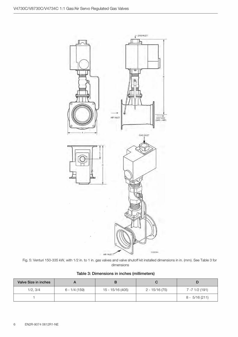
V4730C/V8730C/V4734C 1:1 Gas/Air Servo Regulated Gas Valves
6 EN2R-9074 0612R1-NE
Fig. 5: Venturi 150-335 kW, with 1/2 in. to 1 in. gas valves and valve shutoff kit installed dimensions in in. (mm). See Table 3 for dimensions
Table 3: Dimensions in inches (millimeters)
Valve Size in inches A B C D
1/2, 3/4 6 - 1/4 (159) 15 - 15/16 (405) 2 - 15/16 (75) 7 -7 1/2 (191)
1 8 - 5/16 (211)

V4730C/V8730C/V4734C 1:1 Gas/Air Servo Regulated Gas Valves
EN2R-9074 0612R1-NE 7
Fig. 6: Venturi 500kW, with V4730 gas vlave and valve shutoff kit installed, dimensions in in. (mm), part 1.

V4730C/V8730C/V4734C 1:1 Gas/Air Servo Regulated Gas Valves
8 EN2R-9074 0612R1-NE
Fig. 7: Venturi, 500 kW, with V4730 gas valve and valve shutoff kit installed, dimensions in in. (mm), part 2

V4730C/V8730C/V4734C 1:1 Gas/Air Servo Regulated Gas Valves
EN2R-9074 0612R1-NE 9
Fig. 8: V4734 + VMU 500/680

V4730C/V8730C/V4734C 1:1 Gas/Air Servo Regulated Gas Valves
10 EN2R-9074 0612R1-NE
Fig. 9: Capacity curves for V4730C/V8730C and VMU 150 Venturi, 1/2 in. size.
Fig. 10: Capacity curves for V4730C/V8730C and VMU 300 Venturi, 3/4 in. size

V4730C/V8730C/V4734C 1:1 Gas/Air Servo Regulated Gas Valves
EN2R-9074 0612R1-NE 11
Fig. 11: Capacity curves for V4730C/V8730C and VMU 300 Venturi, 1 in. size.
Fig. 12: Capacity curves for V4730C/V8730C and VMU 335 Venturi, 1-1/4 in. size.

V4730C/V8730C/V4734C 1:1 Gas/Air Servo Regulated Gas Valves
12 EN2R-9074 0612R1-NE
Fig. 14: Capacity curves for V4734C/V8734C and VMU 680 Venturi, 1-1/4 in. size.
Fig. 13: Capacity curves for V4730C/V8730C and VMU 500 Venturi, 1-1/4 in. size.

V4730C/V8730C/V4734C 1:1 Gas/Air Servo Regulated Gas Valves
EN2R-9074 0612R1-NE 13
INSTALLATION
When Installing This Product...1. Read these instructions carefully. Failure to follow them could
damage the product or cause a hazardous condition.
2. Check the ratings given in the instructions and on the pro-duct to make sure the product is suitable for your application.
3. The installer must be a trained, experienced, flame safeguard technician.
4. After installation is complete, check out product operation as provided in these instructions
Mounting PositionThe valve/venturi is factory-calibrated in the upright position for the most accurate metering of the gas flow.This is with the air flow through the venturi in a horizontal direction and the gas flow into the valve in a horizontal direction. The valve can be mounted up to ±90 degrees from this position without affecting the fuel/air metering at medium and high firing rates (3000 to 5000 rpm of the blower), but at lower firing rates (1000 rpm) the fuel might be reduced up to 10% when the valve is not mounted upright. To counter this, the low fire gas flow may be carefully field adjusted for non-upright mounting as follows:
1. With the valve in the final mounting position, adjust the venturifan for the lowest burner firing rate.
2. Remove the slotted cap on the gas regulator using a slotted screwdriver. This will expose the offset adjustment screw (see Fig. 11).
3. Using a TORX® T40 or a 5 mm hex wrench, carefully adjust the low fire gas setting for proper combustion.
4. After proper low fire offset adjustment has been made, rein-stall the slotted cap on the regulator.
5. Before commissioning the burner, check for proper lightoff and verify correct fuel/air mix and combustion quality through out the entire firing range (from lowest to highest fan speeds used).
Mounting LocationsThe distance between the gas valve and the wall/ground must be a minimum of 11-5/16 in. (30 cm).
Fig. 15: Regulating adjusting screw
Main Gas Connection1. Take care that dirt does not enter the gas valve during hand-
ling.
2. Remove the flanges from the valves.
3. Use new, properly reamed, pipe, free from chips.
4. Apply a moderate amount of good quality pipe dope, resi-stant to the action of liquefied petroleum (LP) gas, only on the pipe threads.
5. Screw the flanges onto the pipes.
6. Do not thread the pipe too far into the flange. Valve distortion or malfunction can result from excess pipe in the flange.
7. Make sure O-ring sealing surfaces are clean.
8. Using general purpose lithium grease, grease the O-ring.
9. Install the O-ring into the O-ring groove provided on the valve body (one O-ring per groove).
10. Mount the gas valve to the flanges, using the screws remo-ved earlier.
11. Complete the electrical connections as instructed in the Electrical Connections section.
WARNINGFire or Explosion Hazard. Can cause severe injury, death or property damage
1. Turn off the gas supply before beginning installati-on
2. Disconnect power to the valve actuator before be-ginning installation to prevent electrical shock and damage to the equipment.
3. Do not remove the seal over the valve inlet and outlet until ready to connect piping.
4. The valve must be installed so that the arrow on the valve points in the direction of the gas flow, so that gas pressure helps to close the valve
WARNINGFire or Explosion Hazard. Can cause severe inju-ry, death or property damage.
Perform a soap-and-water solution gas leak test any time work is done on a gas system.

V4730C/V8730C/V4734C 1:1 Gas/Air Servo Regulated Gas Valves
EN2R-9074 0612R1-NE
ELECTRICAL CONNECTIONS
Wiring1. Use 14, 16 or 18 AWG copper conductor, 600 volt insulation,
moisture-resistant wire for line voltage connections. Recom-mended wire types are TTW60C, THW75C or THHN90C.
2. Follow the instructions below for wiring the gas valve. See Fig. 16 and 17 for reference.
2.a T1 (yellow) will be L2 (120 Vac or 24 Vac).
2.b T2 (black) will be L1 (120 Vac or 24 Vac) to Valve 1.
2.c T3 (blue) will be L1 (120 Vac or 24 Vac) to Valve 2.
2.d Ground (green) will be earth ground.
Fig. 16: Four-pin electrical plug connector
Fig. 17: Electrical connection diagram
WARNINGElectrical Shock Hazard. Can cause severe injury or death.
Disconnect the power supply before beginning wiring to prevent electrical shock. More than one disconnect may be involved.
ADJUSTMENTS AND FINAL CHECKOUTThe following procedures are related to the adjustments on the main gas valve. For adjustments of the other devices (i.e., pres-sure switches), refer to the instructions supplied with the applica-ble device.
Pressure Tap Points (Fig. 18)The V4730C/V8730C/V4734C Valves have a number of connec-tion points (1/8 in. [3 mm] NPT plugs) for measuring pressure and/or mounting a pressure switch. The pressure tap points are:
1 inlet pressure at first SSOV flange tap.2 inlet pressure at first SSOV.P outlet pressure at first SSOV.3 inlet pressure at second SSOV.4 outlet pressure at second SSOV flange tap.
The following pressures can be measured:
1. Inlet pressure-tap on inlet flange (1).
2. Pressure after inlet screen (2).
3. Unregulated intermediate pressure-pressure between the two shutoff seats (P).
4. Regulated intermediate pressure-pressure between the shu-toff valves (3).
5. Outlet pressure-tap from flange (4).
The corresponding numbers (2, P, 3) can be found on the side of the valve.
Note: To mount the C6097 Pressure Switch, refer to instructionsin form number 65-0237, furnished with the switch. Thepressure switch can be mounted to 2, P, or 3 on eitherside of the valve.
Fig. 18: Pressure tap points
Second Valve, Fast OpeningFlow rate is adjusted from 0% to 100% of full rated flow. To ad-just the flow rate:
1. Remove the flat, round, blue plastic cap from the cover.Using a 3 mm (7/64 in.) hex wrench, turn the adjustmentscrew counterclockwise to increase or clockwise to decreasethe flow rate.
2. Snap the flat, round, blue plastic cap back onto the cover.
Final Checkout of the InstallationSet the system in operation after any adjustment is completed and observe several complete cycles to ensure that all burner components function correctly.
WARNINGFire or Explosion Hazard.
Can cause severe injury, death or property da-mage.
Only fully qualified, experienced, flame safeguard technicians should make adjustments on the valve.

V4730C/V8730C/V4734C 1:1 Gas/Air Servo Regulated Gas Valves
EN2R-9074 0612R1-NE 15
OPERATIONThe V4730C/V8730C/V4734C are normally closed valves. The valves open when energized and close when power is removed.
1. Do not put the system into service until you have satisfactorilycompleted the Valve Leak Test, all applicable tests describedin the Checkout section of the instructions for the flame safe-guard control, and any other tests required by the burner ma-nufacturer.
2. All tests must be performed by a trained, experienced, flame safeguard technician.
3. Close all manual fuel shutoff valves immediately if trouble oc-curs.
After the installation is complete, cycle the valve several times with the manual fuel shutoff valve cock closed. Make sure the val-ve functions properly. Also, perform the Valve Leak Test before putting the valve into service.
Valve Leak Test (Fig. 19)This is a test for checking the closure tightness of the gas shutoff valve. It should be performed only by trained, experienced, flame safeguard technicians during the initial startup of the burner sys-tem or whenever the valve is replaced. It is recommended that this test should also be included in the scheduled inspection and maintenance procedures. For a periodic inspection test, follow steps 1, 3, 4, 5, 8, 9, 10, 12, 13, 17, and 18.
1. De-energize the control system to make sure no power goesto the valves.
2. Close the upstream manual gas cock (A).
3. Make sure the manual test petcock (F) is closed in the leak test tap assembly.
4. To test the first SSOV, remove the 1/8 in. (3mm) NPT plug from pressure tap point P.
5. Install the leak test tap into pressure tap point P on the valve body.
6. Open the upstream manual gas cock (A) to repressurize the first SSOV.
7. Immerse the 1/4 in. (6 mm) tube vertically 1/2 in. (13 mm) in a jar of water.
8. Slowly open the manual test petcock (F).
9. When the rate of bubbles coming through the water stabili-zes, count the number of bubbles appearing during a ten-se-cond period. Each bubble appearing represents a flow rate of 0.001 cfh (28 cch). See Table 4.
10. Close the upstream manual gas cock (A).
11. Remove the leak test tap from the valve body.
12. Using a small amount of pipe sealant on the 1/8 in. (3 mm) NPT plug, reinstall the plug in pressure tap point P
13. To test the second SSOV, remove the 1/8 in. (3 mm) NPT plug from the flange pressure tap point 4.
14. Install the leak test tap into pressure tap point 4.
15. Close the downstream manual gas cock (E).
16. Energize the first SSOV
Table 4: max. bubbles per pipe size
17. Immerse the 1/4 in. (6 mm) tube vertically 1/2 in. (13mm) into a jar of water.
18. Slowly open the manual test petcock (F).
19. When the rate of bubbles coming through the water stabili-zes, count the number of bubbles appearing during a ten-se-cond period. Each bubble appearing during a 10-second period represents a flow rate of 0.001 cfh (28 cch). See Table 4.
20. De-energize First SSOV
21. Remove the leak test tap from the valve body.
22. Using a small amount of pipe sealant on the 1/8 in. (3 mm) NPT plug, reinstall the plug in pressure tap point 4.
Fig. 19: Valve leak test
After the Test1. . Make sure the downstream manual gas cock (E) is closed.
2. Open the upstream manual gas cock (A) and energize the valve through the safety system.
3. Test with rich soap and water solution to make sure there is no leak at the test tap (D) or any pipe adapter/valve mating surfaces.
4. De-energize the valve (C).
5. Open the downstream manual gas cock (E).
6. Restore the system to normal operation.
WARNINGExplosion and Electrical Shock Hazard. Can cau-se severe injury, death or property damage.
WARNINGElectrical Shock Hazard. Can cause severe injury or death.
Remove the power from the system before beginning the valve leak test to prevent electrical shock. More than one disconnect may be involved.
Pipe Size (in. NPT) Maximum Seat Leakage (UL)
Maximum Number of Bubbles in 10
seconds1/2 - 3/4 235 cch 6
1 275 cch 71 - 1/4 340 cch 8

Automation & Control SolutionsCombustion Controls EuropeHoneywell BVPhileas Foggstraat 77821 AJ EmmenThe NetherlandsTel.: +31 (-) 591 695911Fax.: +31 (-) 591 695200http://europe.hbc.honeywell.com
V4730C/V8730C/V4734C 1:1 Gas/Air Servo Regulated Gas Valves
Manufactured for and on behalf of the Environment and Combustion ControlsDivision of Honeywell Technologies Sàrl,Ecublens, Route du Bois 37, Switzerlandby its Authorised Representative.
Subject to change without notice© 2006 Automation & Control SolutionsCombustion Controls Europe
TROUBLESHOOTING
Troubleshooting ProcedureIf the valve does not open when the thermostat or controller
calls for heat:
1. Check for voltage at the valve leadwires or terminal block.
2. If there is no voltage at the valve leadwires or terminal block, make sure:
2.a voltage is connected to the master switch.
2.b master switch is closed and overload protection (circuit breaker, fuse, or similar device) has notopened the po-wer line.
3. If there is still no voltage at the valve leadwires or terminal block, make sure all appropriate contacts in the thermostat or controller, limits and flame safeguard control are closed. If one or more are open, determine the cause(s); correct the trouble and proceed.
4. If there is proper voltage at the valve but the valve still does not open, check for normal gas pressure.
5. If the valve still does not open, replace the valve.
If the valve does not close when one or more of the appropriate contacts in the thermostat, controller, limits or flame safeguard control is open:
1. Make sure the valve is wired in the correct circuit.
2. Open the master switch to remove power from the valve.
3. If the valve closes now, check the wiring for the valve and cor-rect the wiring as necessary.
4. Check for a short in the electrical circuit and repair it as ne-cessary.
WARNINGElectrical Shock Hazard. Can cause severe inju-ry, death or property damage.
Use extreme caution when troubleshooting; line volta-ge is present.
IMPORTANTDo not replace the valve until all other sources of trouble are eliminated.
SERVICE INFORMATION
Scheduled Inspection and Maintenance
Set up and follow a schedule for periodic inspection and mainte-nance, including the burner, all other controls and the valves. It is recommended that the valve leak test in the Checkout section be included in this schedule. Refer to the instructions for the primary safety control (s) 0 for more inspection and maintenance informa-tion.
Screen/Strainer Replacement1. Make sure the gas supply is turned off and all electrical
power has been removed.
2. Remove bolts/nuts from flange/valve.
3. Remove flange from gas supply pipe.
4. Remove old screen/strainer.
5. Clean the strainer by using compressed air, or replace the strainer.
6. Install the cleaned strainer or new strainer.
7. Make sure O-ring sealing surface is clean on the flange.
8. Using general purpose lithium grease, grease the O-ring.
9. Apply a moderate amount of good quality pipe dope, resi-stant to the action of LP gas, only on the pipe threads.
10. Install the O-ring in the O-ring groove provided on the flange/valve body (one O-ring per groove).
11. Screw the flange onto the pipe.
12. Mount the gas valve to the flange, using the bolts and nuts for each flange.
13. Apply power to the valve.
14. Turn on the main gas supply.
15. Complete the valve leak test.
16. Return the valve to service.
WARNINGExplosion Hazard and Electrical Shock Hazard. Can cause severe injury, death or property da-mage.
Turn off gas supply and disconnect all electrical power to the valve before servicing.
IMPORTANTOnly trained, experienced, flame safeguard technici-ans should attempt to service or repair flame safe-guard controls and burner assemblies.
EN0H-0281NL05-R1006


e-mail: [email protected] Address: http://www.cleaver-brooks.com