
CleanStar iComLine - gemu-group.com
14
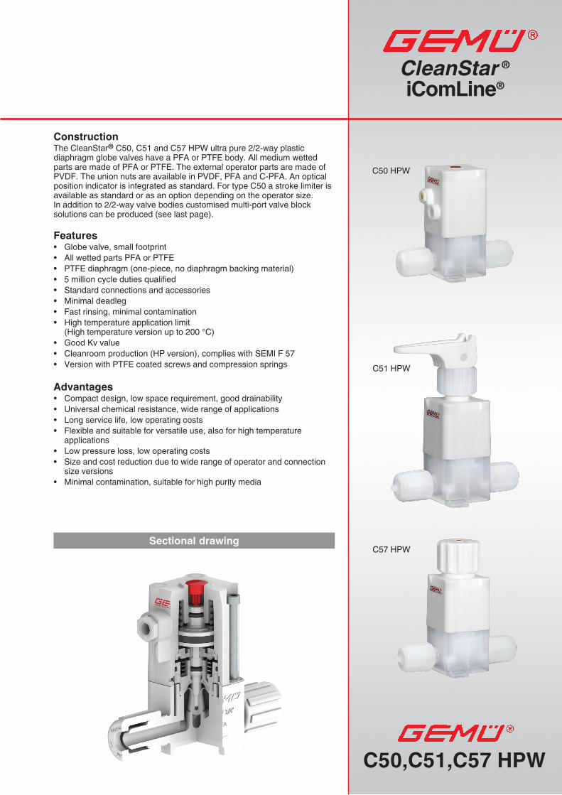
C50,C51,C57 HPW C50 HPW C51 HPW C57 HPW CleanStar ® iComLine ® Sectional drawing Construction The CleanStar ® C50, C51 and C57 HPW ultra pure 2/2-way plastic diaphragm globe valves have a PFA or PTFE body. All medium wetted parts are made of PFA or PTFE. The external operator parts are made of PVDF. The union nuts are available in PVDF, PFA and C-PFA. An optical position indicator is integrated as standard. For type C50 a stroke limiter is available as standard or as an option depending on the operator size. In addition to 2/2-way valve bodies customised multi-port valve block solutions can be produced (see last page). Features • Globe valve, small footprint • All wetted parts PFA or PTFE • PTFE diaphragm (one-piece, no diaphragm backing material) • 5 million cycle duties qualified • Standard connections and accessories • Minimal deadleg • Fast rinsing, minimal contamination • High temperature application limit (High temperature version up to 200 °C) • Good Kv value • Cleanroom production (HP version), complies with SEMI F 57 • Version with PTFE coated screws and compression springs Advantages • Compact design, low space requirement, good drainability • Universal chemical resistance, wide range of applications • Long service life, low operating costs • Flexible and suitable for versatile use, also for high temperature applications • Low pressure loss, low operating costs • Size and cost reduction due to wide range of operator and connection size versions • Minimal contamination, suitable for high purity media
Transcript of CleanStar iComLine - gemu-group.com
C50,C51,C57 HPW
C50 HPW
C51 HPW
C57 HPW
CleanStar ® iComLine®
Sectional drawing
ConstructionThe CleanStar® C50, C51 and C57 HPW ultra pure 2/2-way plastic diaphragm globe valves have a PFA or PTFE body. All medium wetted parts are made of PFA or PTFE. The external operator parts are made of PVDF. The union nuts are available in PVDF, PFA and C-PFA. An optical position indicator is integrated as standard. For type C50 a stroke limiter is available as standard or as an option depending on the operator size. In addition to 2/2-way valve bodies customised multi-port valve block solutions can be produced (see last page).
Features• Globe valve, small footprint• All wetted parts PFA or PTFE• PTFE diaphragm (one-piece, no diaphragm backing material)• 5 million cycle duties qualified• Standard connections and accessories• Minimal deadleg• Fast rinsing, minimal contamination• High temperature application limit
(High temperature version up to 200 °C)• Good Kv value• Cleanroom production (HP version), complies with SEMI F 57• Version with PTFE coated screws and compression springs
Advantages • Compact design, low space requirement, good drainability• Universal chemical resistance, wide range of applications• Long service life, low operating costs• Flexible and suitable for versatile use, also for high temperature
applications• Low pressure loss, low operating costs• Size and cost reduction due to wide range of operator and connection
size versions• Minimal contamination, suitable for high purity media
2C50, C51, C57
320 338 356 374
Temperatur [°F]
Temperatur [°C]
392 410
Dru
ck [b
ar]
Dru
ck [P
SI]
-4 14 32 50 68 86 104 122 140 158 176 194 212 230 248 266 284 302
- 20 -10 0 10 20 30 40 50 60 70 80 90 100 110 120 130 140 150
7654321
105907560453015AG 3,4
AG 0,1,2160 190180170
AG 1AH
AG 2 AH200 210
General technical data
Flow directionIt is indicated by an arrow on the valve body
MaterialsMedia wetted parts (body) PFA and PTFEDiaphragm PTFEExternal operator parts PVDF
Working mediumCorrosive, inert, gaseous and liquid media - particularly high purity media - which have no negative impact on the physical and chemical properties of the body and diaphragm material.
Ambient temperatureMax. 60 °C (130 °F)
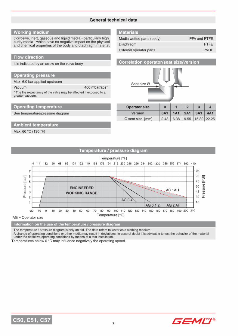
Operating temperatureSee temperature/pressure diagram
Temperature / pressure diagram
Information on the use of the temperature / pressure diagramThe temperature / pressure diagram is only an aid. The data refers to water as a working medium. A change of operating conditions or other media may result in deviations. In case of doubt it is advisable to test the behavior of the material under the definitive operating conditions by means of a test installation.
ENGINEEREDWORKING RANGE
Seat size Ø
Operating pressureMax. 6.0 bar applied upstreamVacuum 400 mbar/abs** The life expectancy of the valve may be affected if exposed to a greater vacuum.
Correlation operator/seat size/version
Temperature [°F]
Temperature [°C]
Pres
sure
[bar
]
Pres
sure
[PSI
]
Operator size 0 1 2 3 4Version 0A1 1A1 2A1 3A1 4A1
Ø seat size [mm] 2.48 6.38 9.55 15.80 22.25
Temperatures below 0 °C may influence negatively the operating speed.
AG = Operator size
3 C50, C51, C57
103
88
73
59
44
1170.14 0.210.29 0.36 0.430.07 0.57 0.65 0.720.5
2 3 4 5 60 1 8 9 107
6
5
4
3
AG1 - 1/4" AG1 - 3/8", 1/2"AG0 - 1/4"7
8
11 12
0.79 1.44 2.89 4.32 5.76 7.12 8.64 10.08
7
6
5
4
3
20 40 60 80 100 120 1400
AG2 - 1/2", 3/4"AG3 - 3/4", 1"
8AG4 - 1", 1¼" 103
88
73
59
44
117
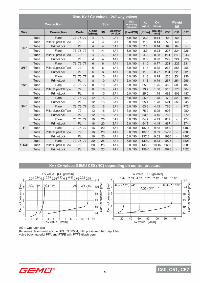
Kv / Cv values GEMÜ C50 (NC) depending on control pressure
Max. Kv / Cv values - 2/2-way valves
Connection SizeMax.
operating pressure
Kv value
Cv value
Weight [g]
Size Connection Code Code intern. DN Operator
version [bar/PSI] [l/min] [US gal/min] C50 C51 C57
1/4”
Tube Flare 73. 75. 77 4 4 0A1 6.0 / 90 2.0 0.14 58 60 -Tube Pillar Super 300 Type 79 4 4 0A1 6.0 / 90 2.0 0.14 58 60 -Tube PrimeLock PL 4 4 0A1 6.0 / 90 2.0 0.14 62 64 -Tube Flare 73. 75. 77 4 4 1A1 6.0 / 90 3.3 0.23 227 224 226Tube Pillar Super 300 Type 79 4 4 1A1 6.0 / 90 4.0 0.28 251 243 243Tube PrimeLock PL 4 4 1A1 6.0 / 90 3.3 0.23 227 224 226
3/8”Tube Flare 73. 75. 77 6 6 1A1 6.0 / 90 11.0 0.77 231 229 231Tube Pillar Super 300 Type 79 6 6 1A1 6.0 / 90 11.7 0.82 263 255 255Tube PrimeLock PL 6 6 1A1 6.0 / 90 11.0 0.77 231 229 231
1/2”
Tube Flare 73. 75. 77 8 10 1A1 6.0 / 90 11.3 0.79 236 234 236Tube PrimeLock PL 8 10 1A1 6.0 / 90 11.3 0.79 257 254 256Tube Flare 73. 75. 77 8 10 2A1 6.0 / 90 25.0 1.75 462 509 487Tube Pillar Super 300 Type 79 8 10 2A1 6.0 / 90 23.7 1.66 513 578 564Tube PrimeLock PL 8 10 2A1 6.0 / 90 25.0 1.75 462 509 487
3/4”
Tube Flare 73. 75. 77 12 15 2A1 6.0 / 90 25.4 1.78 473 520 498Tube PrimeLock PL 12 15 2A1 6.0 / 90 25.4 1.78 521 568 545Tube Flare 73. 75. 77 12 15 3A1 6.0 / 90 63.6 4.45 765 - 772Tube Pillar Super 300 Type 79 12 15 3A1 6.0 / 90 75.0 5.25 908 - 950Tube PrimeLock PL 12 15 3A1 6.0 / 90 63.6 4.45 765 - 772
1”
Tube Flare 73. 75. 77 16 20 3A1 6.0 / 90 64.2 4.49 817 - 774Tube PrimeLock PL 16 20 3A1 6.0 / 90 64.2 4.49 867 - 874Tube Flare 73. 75. 77 16 20 4A1 6.0 / 90 137.5 9.63 1930 - 1480Tube Pillar Super 300 Type 79 16 20 4A1 6.0 / 90 137.0 9.59 2450 - 2000Tube PrimeLock PL 16 20 4A1 6.0 / 90 137.5 9.63 1930 - 1480
1 1/4”Tube Flare 73. 75. 77 20 25 4A1 6.0 / 90 139.0 9.73 1973 - 1523Tube Pillar Super 300 Type 79 20 25 4A1 6.0 / 90 145.0 10.15 2650 - 2200Tube PrimeLock PL 20 25 4A1 6.0 / 90 139.0 9.73 1973 - 1523
Kv value [l/min] Kv value [l/min]
Cv value [US gal/min] Cv value [US gal/min]
Con
trol p
ress
ure
[bar
]
Con
trol p
ress
ure
[PSI
]
Con
trol p
ress
ure
[bar
]
Con
trol p
ress
ure
[PSI
]
Kvvaluesdeterminedacc.toDINEN60534,inletpressure6bar,Δp1bar, valve body material PFA and PTFE with PTFE diaphragm.
AG = Operator size
4C50, C51, C57
0
2
68
1012
4
1614
1/4 1/2 3/4 1 1¾1½1¼
3/8", 1/2"
1/4"
AG1
0.14
0.420.560,700.84
0.28
1.120.98
0
5
15202530
10
35
1/4 1/2 3/4 1 1¾1½1¼
0.35
1.051.391.742.09
0.70
2.44
3/4"
1/2"
AG2
0 1/4 1/2 3/4 1
20304050
10
7060
1¾1½1¼
2.091.39
3.494.19
1.05
2.79
4.88
AG3
3/4", 1"
1.39
4.195.586.988.37
2.79
11.169.77
0 1/2 1 31½ 2 2½ 3½ 4
20
6080
100120
40
160140
AG4
1", 1¼"
0 654321
1,52,02,53,03,54,0
4,5 907560453015
233038455260
68
AG0
AG1
AG2
AG3
AG4
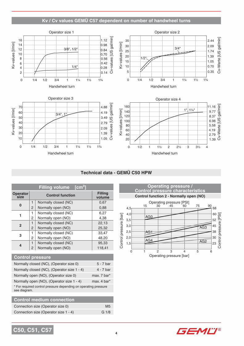
Kv / Cv values GEMÜ C57 dependent on number of handwheel turns
Kv-v
alue
s [l/
min
]
Cv-
valu
es [U
S ga
l/min
]
Kv-v
alue
s [l/
min
]
Cv-
Wer
te [U
S ga
l/min
]
Kv-v
alue
s [l/
min
]
Cv-
valu
es [U
S ga
l/min
]
Kv-v
alue
s [l/
min
]
Cv-
Wer
te [U
S ga
l/min
]
Handwheel turn Handwheel turn
Handwheel turnHandwheel turn
Operator size 1 Operator size 2
Operator size 4Operator size 3
Technical data - GEMÜ C50 HPW
Control pressureNormally closed (NC), (Operator size 0) 5 - 7 barNormally closed (NC), (Operator size 1 - 4) 4 - 7 barNormally open (NO), (Operator size 0) max. 7 bar*Normally open (NO), (Operator size 1 - 4) max. 4 bar** For required control pressure depending on operating pressure see diagram.
Control medium connectionConnection size (Operator size 0) M5Connection size (Operator size 1 - 4) G 1/8
Filling volume [cm³]Operator
size Control function Filling volume
01 Normally closed (NC) 0,672 Normally open (NO) 0,88
1 1 Normally closed (NC) 6,272 Normally open (NO) 4,38
2 1 Normally closed (NC) 22,132 Normally open (NO) 25,32
3 1 Normally closed (NC) 33,472 Normally open (NO) 48,20
4 1 Normally closed (NC) 95,332 Normally open (NO) 118,41
Operating pressure / Control pressure characteristicsControl function 2 - Normally open (NO)
Operating pressure [bar]
Con
trol p
ress
ure
[bar
]
Operating pressure [PSI]
Con
trol p
ress
ure
[PSI
]
5 C50, C51, C57
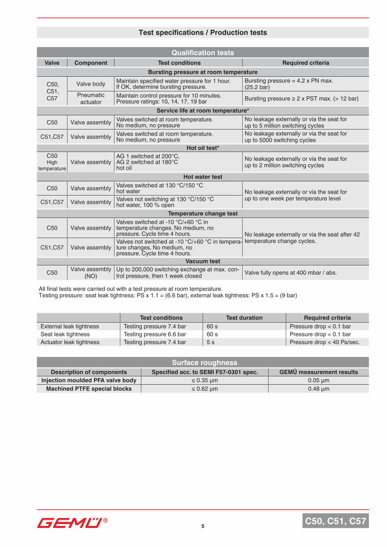
Test conditions Test duration Required criteriaExternal leak tightness Testing pressure 7.4 bar 60 s Pressure drop < 0.1 barSeat leak tightness Testing pressure 6.6 bar 60 s Pressure drop < 0.1 barActuator leak tightness Testing pressure 7.4 bar 5 s Pressure drop < 40 Pa/sec.
Qualification testsValve Component Test conditions Required criteria
Bursting pressure at room temperature
C50, C51, C57
Valve body Maintain specified water pressure for 1 hour. If OK, determine bursting pressure.
Bursting pressure = 4.2 x PN max. (25.2 bar)
Pneumatic actuator
Maintain control pressure for 10 minutes. Pressure ratings: 10, 14, 17, 19 bar Burstingpressure≥2xPSTmax.(>12bar)
Service life at room temperature*
C50 Valve assembly Valves switched at room temperature. No medium, no pressure
No leakage externally or via the seat for up to 5 million switching cycles
C51,C57 Valve assembly Valves switched at room temperature. No medium, no pressure
No leakage externally or via the seat for up to 5000 switching cycles
Hot oil test*C50 High
temperatureValve assembly
AG 1 switched at 200°C, AG 2 switched at 180°C hot oil
No leakage externally or via the seat for up to 2 million switching cycles
Hot water test
C50 Valve assembly Valves switched at 130 °C/150 °C hot water No leakage externally or via the seat for
up to one week per temperature levelC51,C57 Valve assembly Valves not switching at 130 °C/150 °C hot water, 100 % open
Temperature change test
C50 Valve assemblyValves switched at -10 °C/+60 °C in temperature changes. No medium, no pressure. Cycle time 4 hours. No leakage externally or via the seat after 42
temperature change cycles.C51,C57 Valve assembly
Valves not switched at -10 °C/+60 °C in tempera-ture changes. No medium, no pressure. Cycle time 4 hours.
Vacuum test
C50 Valve assembly(NO)
Up to 200,000 switching exchange at max. con-trol pressure, then 1 week closed Valve fully opens at 400 mbar / abs.
Test specifications / Production tests
Surface roughnessDescription of components Specified acc. to SEMI F57-0301 spec. GEMÜ measurement results
Injection moulded PFA valve body ≤0.35µm 0.05µmMachined PTFE special blocks ≤0.62µm 0.48µm
All final tests were carried out with a test pressure at room temperature.Testing pressure: seat leak tightness: PS x 1.1 = (6.6 bar), external leak tightness: PS x 1.5 = (9 bar)
6C50, C51, C57
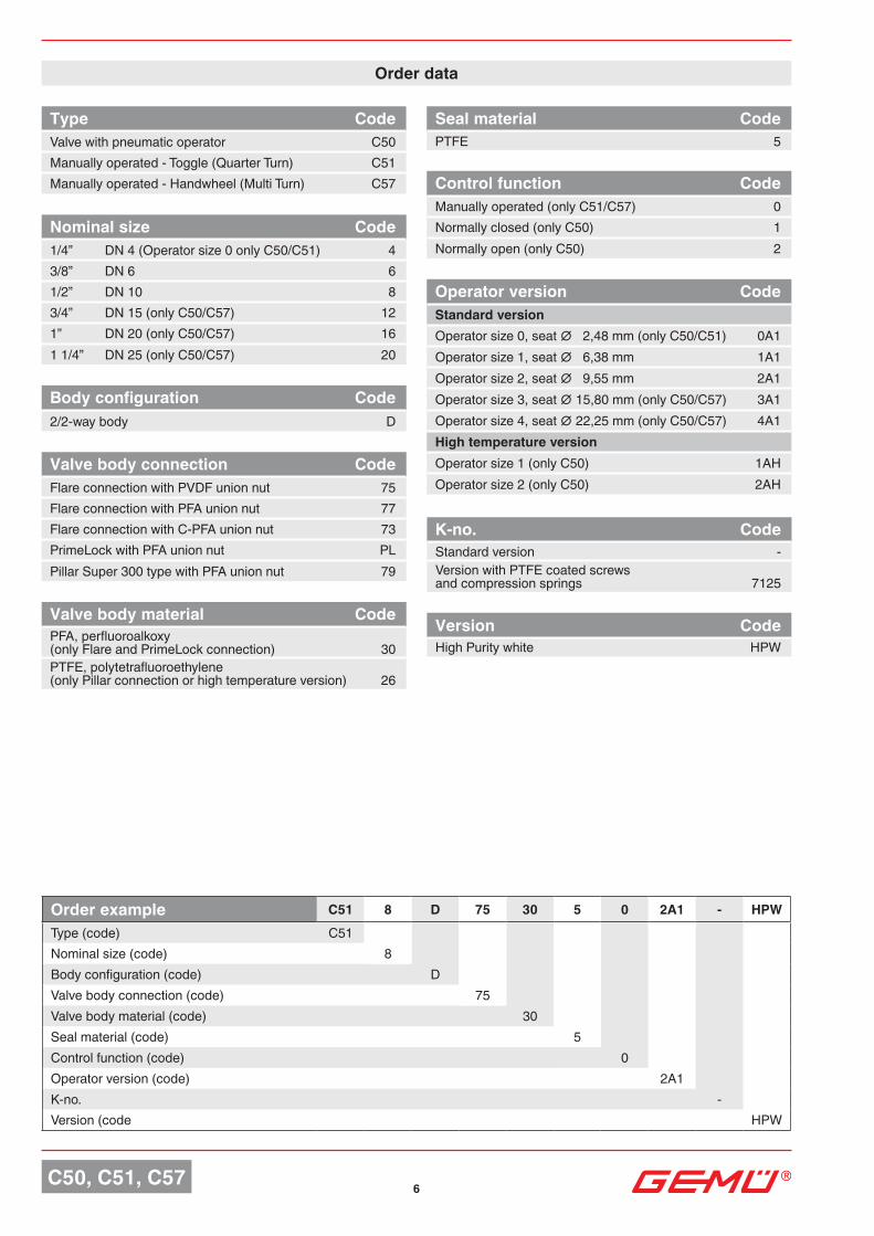
Order data
Type CodeValve with pneumatic operator C50Manually operated - Toggle (Quarter Turn) C51Manually operated - Handwheel (Multi Turn) C57
Body configuration Code2/2-way body D
Valve body connection CodeFlare connection with PVDF union nut 75Flare connection with PFA union nut 77Flare connection with C-PFA union nut 73PrimeLock with PFA union nut PLPillar Super 300 type with PFA union nut 79
Seal material CodePTFE 5
Control function CodeManually operated (only C51/C57) 0Normally closed (only C50) 1Normally open (only C50) 2
Version CodeHigh Purity white HPW
Nominal size Code1/4” DN 4 (Operator size 0 only C50/C51) 43/8” DN 6 61/2” DN 10 83/4” DN 15 (only C50/C57) 121” DN 20 (only C50/C57) 161 1/4” DN 25 (only C50/C57) 20
Valve body material CodePFA, perfluoroalkoxy (only Flare and PrimeLock connection) 30PTFE, polytetrafluoroethylene (only Pillar connection or high temperature version) 26
Order example C51 8 D 75 30 5 0 2A1 - HPWType (code) C51Nominal size (code) 8Body configuration (code) DValve body connection (code) 75Valve body material (code) 30Seal material (code) 5Control function (code) 0Operator version (code) 2A1K-no. -Version (code HPW
Operator version CodeStandard versionOperatorsize0,seat∅2,48mm(onlyC50/C51) 0A1Operatorsize1,seat∅6,38mm 1A1Operatorsize2,seat∅9,55mm 2A1Operatorsize3,seat∅15,80mm(onlyC50/C57) 3A1Operatorsize4,seat∅22,25mm(onlyC50/C57) 4A1High temperature versionOperator size 1 (only C50) 1AHOperator size 2 (only C50) 2AH
K-no. CodeStandard version -Version with PTFE coated screws and compression springs 7125
7 C50, C51, C57
A2
A1
A3 B
M5
(A
G 0
) G
1/8
(AG
1 -
4)
A5
H2
E
B1 M
A4
N2
N4 1/2L 1/2L
L
N1
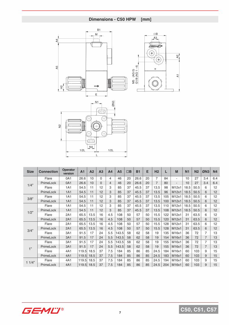
Dimensions - C50 HPW [mm]
Size Connection Operator version A1 A2 A3 A4 A5 □B B1 E H2 L M N1 N2 ØN3 N4
1/4”
Flare 0A1 26.6 10 0 4 46 20 26.6 20 7 84 - 10 27 3.4 6.4PrimeLock 0A1 26.6 10 0 4 46 20 26.6 20 7 80 - 10 27 3.4 6.4
Flare 1A1 54.5 11 12 3 85 37 45.5 37 13.5 98 M12x1 18.5 50.5 6 12PrimeLock 1A1 54.5 11 12 3 85 37 45.5 37 13.5 96 M12x1 18.5 50.5 6 12
3/8” Flare 1A1 54.5 11 12 3 85 37 45.5 37 13.5 105 M12x1 18.5 50.5 6 12PrimeLock 1A1 54.5 11 12 3 85 37 45.5 37 13.5 100 M12x1 18.5 50.5 6 12
1/2”
Flare 1A1 54.5 11 12 3 85 37 45.5 37 13.5 110 M12x1 18.5 50.5 6 12PrimeLock 1A1 54.5 11 12 3 85 37 45.5 37 13.5 108 M12x1 18.5 50.5 6 12
Flare 2A1 65.5 13.5 16 4.5 108 50 57 50 15.5 122 M12x1 31 63.5 6 12PrimeLock 2A1 65.5 13.5 16 4.5 108 50 57 50 15.5 120 M12x1 31 63.5 6 12
3/4”
Flare 2A1 65.5 13.5 16 4.5 108 50 57 50 15.5 128 M12x1 31 63.5 6 12PrimeLock 2A1 65.5 13.5 16 4.5 108 50 57 50 15.5 128 M12x1 31 63.5 6 12
Flare 3A1 91.5 17 24 5.5 143.5 58 62 58 19 135 M16x1 36 72 7 13PrimeLock 3A1 91.5 17 24 5.5 143.5 58 62 58 19 154 M16x1 36 72 7 13
1”
Flare 3A1 91.5 17 24 5.5 143.5 58 62 58 19 155 M16x1 36 72 7 13PrimeLock 3A1 91.5 17 24 5.5 143.5 58 62 58 19 155 M16x1 36 72 7 13
Flare 4A1 119.5 18.5 37 7.5 184 85 86 85 24.5 184 M16x1 60 103 9 15PrimeLock 4A1 119.5 18.5 37 7.5 184 85 86 85 24.5 183 M16x1 60 103 9 15
1 1/4” Flare 4A1 119.5 18.5 37 7.5 184 85 86 85 24.5 194 M16x1 60 103 9 15PrimeLock 4A1 119.5 18.5 37 7.5 184 85 86 85 24.5 204 M16x1 60 103 9 15
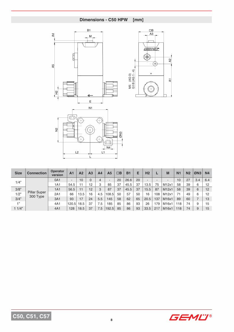
8C50, C51, C57
L
N2
Ø
N3
N4 L1 L2
N1
A5
A4
M
B1
H2
E
A3 □B
A2
A1
M5
(A
G 0
) G
1/8
(AG
1 -
4)
Size Connection Operator version A1 A2 A3 A4 A5 □B B1 E H2 L M N1 N2 ØN3 N4
1/4”
Pillar Super 300 Type
0A1 - 10 0 4 - 20 26.6 20 - - - 10 27 3.4 6.41A1 54.5 11 12 3 85 37 45.5 37 13.5 75 M12x1 58 39 6 12
3/8” 1A1 56.5 11 12 3 87 37 45.5 37 15.5 87 M12x1 58 39 6 121/2” 2A1 66 13.5 16 4.5 108.5 50 57 50 16 108 M12x1 71 49 6 123/4” 3A1 93 17 24 5.5 145 58 62 65 20.5 137 M16x1 89 60 7 131” 4A1 120.5 18.5 37 7.5 185 85 86 93 26 179 M16x1 118 74 9 15
1 1/4” 4A1 128 18.5 37 7.5 192.5 85 86 93 33.5 217 M16x1 118 74 9 15
Dimensions - C50 HPW [mm]
□B
H2
A5A4
E
B1
L
1/2L 1/2L
N2
N4
N1 Ø
N1
9C50, C51, C57
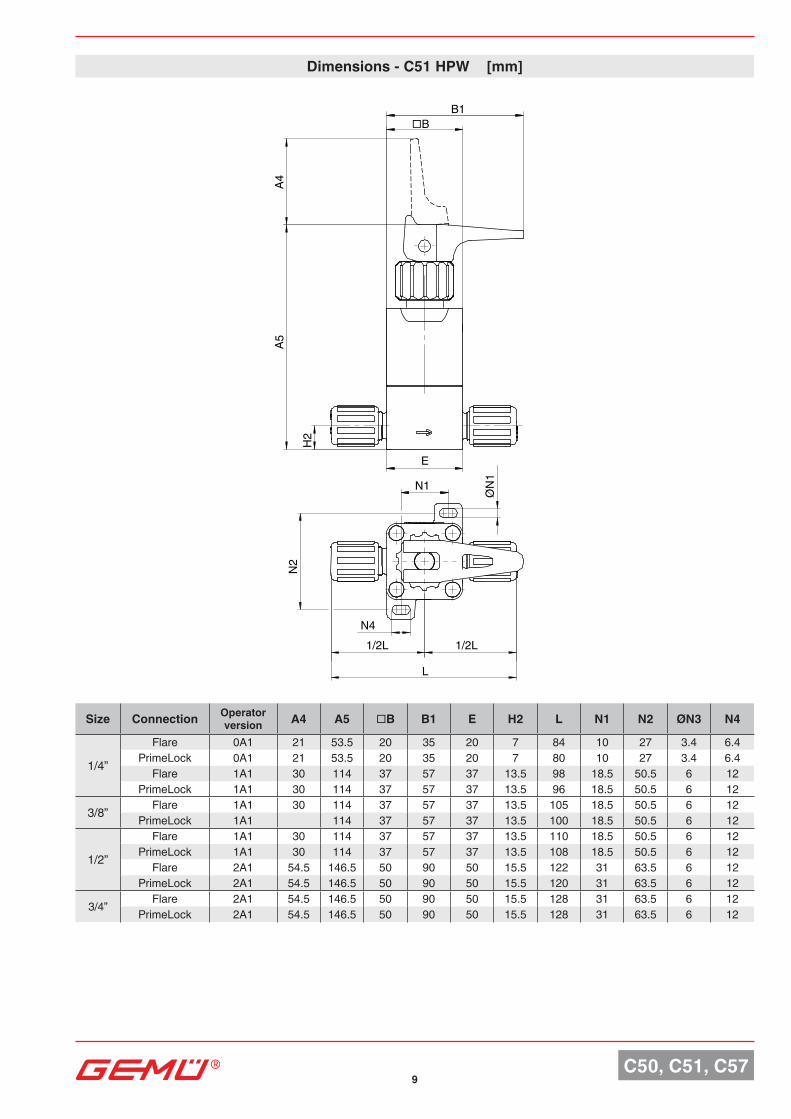
Dimensions - C51 HPW [mm]
Size Connection Operator version A4 A5 □B B1 E H2 L N1 N2 ØN3 N4
1/4”
Flare 0A1 21 53.5 20 35 20 7 84 10 27 3.4 6.4PrimeLock 0A1 21 53.5 20 35 20 7 80 10 27 3.4 6.4
Flare 1A1 30 114 37 57 37 13.5 98 18.5 50.5 6 12PrimeLock 1A1 30 114 37 57 37 13.5 96 18.5 50.5 6 12
3/8” Flare 1A1 30 114 37 57 37 13.5 105 18.5 50.5 6 12PrimeLock 1A1 114 37 57 37 13.5 100 18.5 50.5 6 12
1/2”
Flare 1A1 30 114 37 57 37 13.5 110 18.5 50.5 6 12PrimeLock 1A1 30 114 37 57 37 13.5 108 18.5 50.5 6 12
Flare 2A1 54.5 146.5 50 90 50 15.5 122 31 63.5 6 12PrimeLock 2A1 54.5 146.5 50 90 50 15.5 120 31 63.5 6 12
3/4” Flare 2A1 54.5 146.5 50 90 50 15.5 128 31 63.5 6 12PrimeLock 2A1 54.5 146.5 50 90 50 15.5 128 31 63.5 6 12
10C50, C51, C57
B1
A4
A5
H2
E N
2
N4
L L1 L2
N1
□B
ØN
3
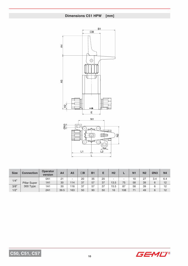
Dimensions C51 HPW [mm]
Size Connection Operator version A4 A5 □B B1 E H2 L N1 N2 ØN3 N4
1/4”Pillar Super 300 Type
0A1 21 - 20 35 20 - - 10 27 3.4 6.41A1 30 114 37 57 37 13.5 75 58 39 6 12
3/8” 1A1 30 116 37 57 37 15.5 87 58 39 6 121/2” 2A1 39.5 163 50 90 50 16 108 71 49 6 12
11 C50, C51, C57
H2
E
A5A4
L1/2L 1/2L
N2
N4
N1
□B
ØN
3
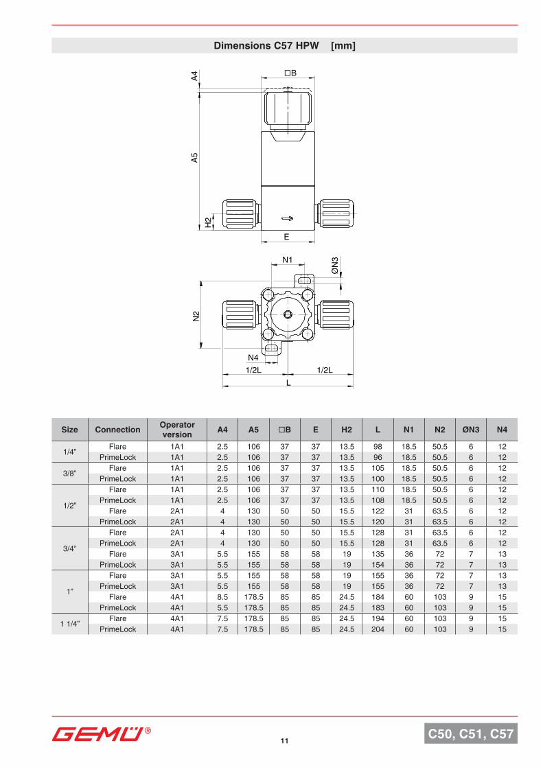
Size Connection Operator version A4 A5 □B E H2 L N1 N2 ØN3 N4
1/4” Flare 1A1 2.5 106 37 37 13.5 98 18.5 50.5 6 12PrimeLock 1A1 2.5 106 37 37 13.5 96 18.5 50.5 6 12
3/8” Flare 1A1 2.5 106 37 37 13.5 105 18.5 50.5 6 12PrimeLock 1A1 2.5 106 37 37 13.5 100 18.5 50.5 6 12
1/2”
Flare 1A1 2.5 106 37 37 13.5 110 18.5 50.5 6 12PrimeLock 1A1 2.5 106 37 37 13.5 108 18.5 50.5 6 12
Flare 2A1 4 130 50 50 15.5 122 31 63.5 6 12PrimeLock 2A1 4 130 50 50 15.5 120 31 63.5 6 12
3/4”
Flare 2A1 4 130 50 50 15.5 128 31 63.5 6 12PrimeLock 2A1 4 130 50 50 15.5 128 31 63.5 6 12
Flare 3A1 5.5 155 58 58 19 135 36 72 7 13PrimeLock 3A1 5.5 155 58 58 19 154 36 72 7 13
1”
Flare 3A1 5.5 155 58 58 19 155 36 72 7 13PrimeLock 3A1 5.5 155 58 58 19 155 36 72 7 13
Flare 4A1 8.5 178.5 85 85 24.5 184 60 103 9 15PrimeLock 4A1 5.5 178.5 85 85 24.5 183 60 103 9 15
1 1/4” Flare 4A1 7.5 178.5 85 85 24.5 194 60 103 9 15PrimeLock 4A1 7.5 178.5 85 85 24.5 204 60 103 9 15
Dimensions C57 HPW [mm]
12C50, C51, C57
□B
ØN
3
E
H2
A5
N2
N4 L1 L2
L
N1
A4
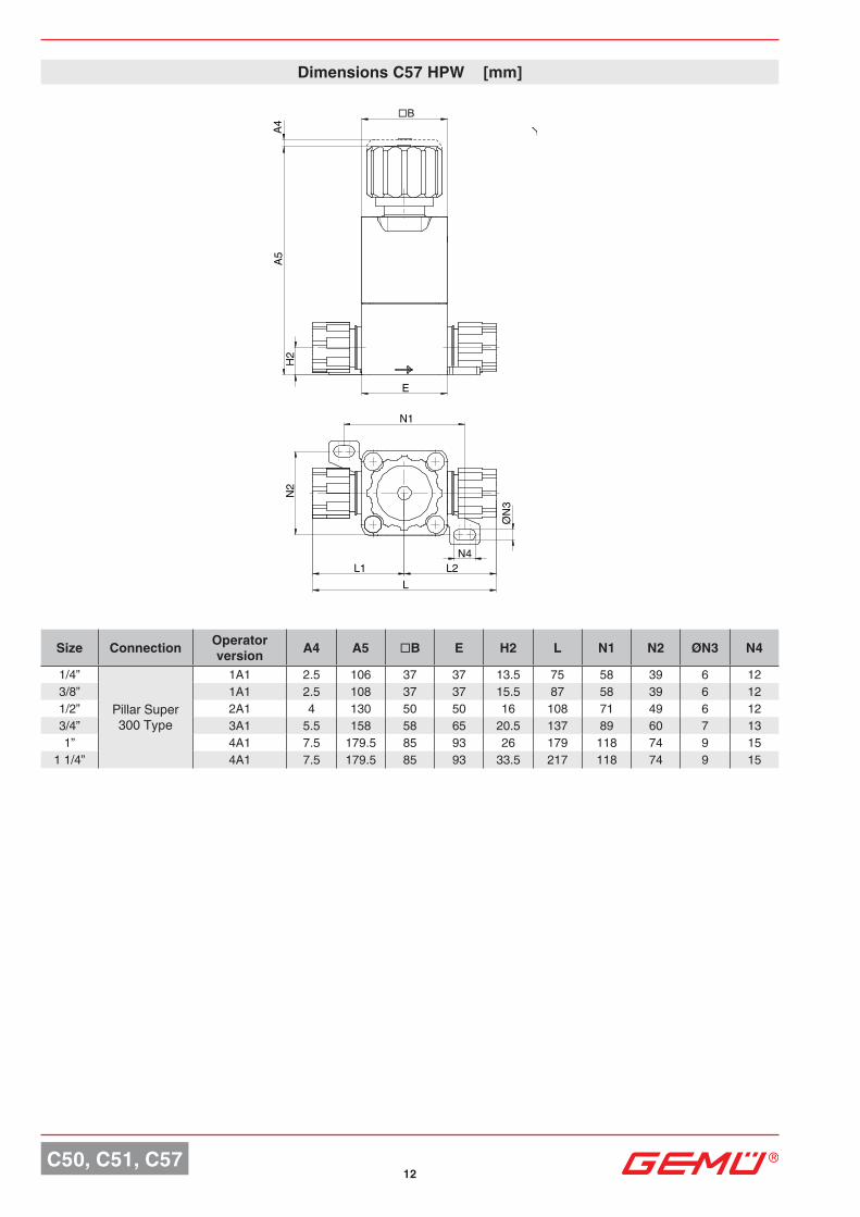
Size Connection Operator version A4 A5 □B E H2 L N1 N2 ØN3 N4
1/4”
Pillar Super 300 Type
1A1 2.5 106 37 37 13.5 75 58 39 6 123/8” 1A1 2.5 108 37 37 15.5 87 58 39 6 121/2” 2A1 4 130 50 50 16 108 71 49 6 123/4” 3A1 5.5 158 58 65 20.5 137 89 60 7 131” 4A1 7.5 179.5 85 93 26 179 118 74 9 15
1 1/4” 4A1 7.5 179.5 85 93 33.5 217 118 74 9 15
Dimensions C57 HPW [mm]
13C50, C51, C57
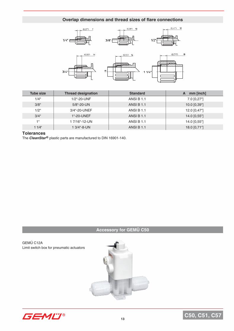
Overlap dimensions and thread sizes of flare connections
Tube size Thread designation Standard A mm [inch]1/4“ 1/2“-20-UNF ANSI B 1.1 7.0 [0,27“]3/8“ 5/8“-20-UN ANSI B 1.1 10.0 [0,39“]1/2“ 3/4“-20-UNEF ANSI B 1.1 12.0 [0,47“]3/4“ 1“-20-UNEF ANSI B 1.1 14.0 [0,55“]1“ 1 7/16“-12-UN ANSI B 1.1 14.0 [0,55“]
1 1/4“ 1 3/4“-8-UN ANSI B 1.1 18.0 [0,71“]TolerancesThe CleanStar® plastic parts are manufactured to DIN 16901-140.
GEMÜ C12ALimit switch box for pneumatic actuators
Accessory for GEMÜ C50
Tech
nica
l dat
a sh
eet
Subj
ect t
o al
tera
tion
· 05/
2020
· 88
3328
50Sh
ould
ther
e be
any
dou
bts o
r misu
nder
stand
ings.
the
Ger
man
vers
ion o
f this
data
shee
t is th
e au
thor
itativ
e do
cum
ent!
For further valves. high purity products. accessories and other products . please see our Product Range catalogue and Price List.
Contact GEMÜ.
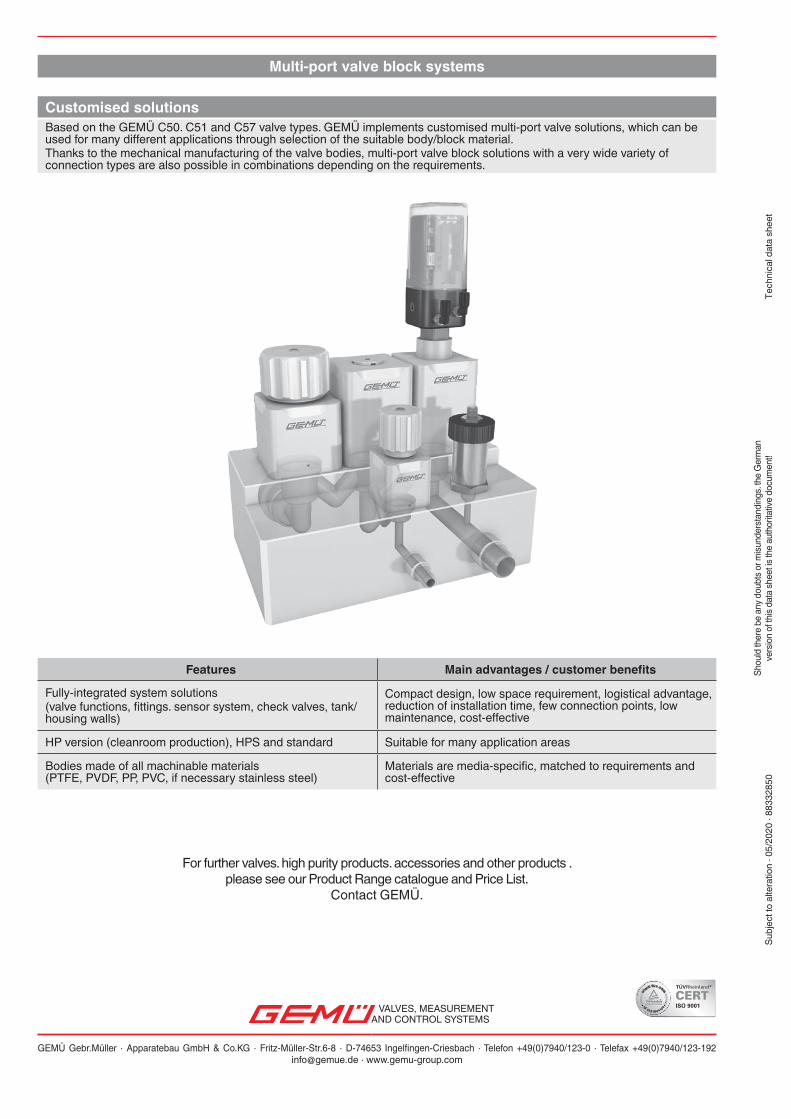
Multi-port valve block systems
Features Main advantages / customer benefits
Fully-integrated system solutions(valve functions, fittings. sensor system, check valves, tank/housing walls)
Compact design, low space requirement, logistical advantage, reduction of installation time, few connection points, low maintenance, cost-effective
HP version (cleanroom production), HPS and standard Suitable for many application areas
Bodies made of all machinable materials (PTFE, PVDF, PP, PVC, if necessary stainless steel)
Materials are media-specific, matched to requirements and cost-effective
Customised solutionsBased on the GEMÜ C50. C51 and C57 valve types. GEMÜ implements customised multi-port valve solutions, which can be used for many different applications through selection of the suitable body/block material.Thanks to the mechanical manufacturing of the valve bodies, multi-port valve block solutions with a very wide variety of connection types are also possible in combinations depending on the requirements.
VALVES, MEASUREMENTAND CONTROL SYSTEMS
GEMÜ Gebr.Müller · Apparatebau GmbH & Co.KG · Fritz-Müller-Str.6-8 · D-74653 Ingelfingen-Criesbach · Telefon +49(0)7940/123-0 · Telefax +49(0)7940/[email protected] · www.gemu-group.com


