
Clause no - eurofitnet.org · Web viewLatest update: 13 September 2010. Comments up to no. 82 are...
26
Comments on and errors in FITNET MK8 Latest update: 13 September 2010 Comments up to no. 82 are on website Ref . Edit . (E) or Tech . (T) Page No. Clause Current wording Suggested replacement, or comment {in brackets} Response from FITNET consortium 1 E 9-20 9.2.5.3.1 Corrode pipe of vessel Corroded pipe or vessel Agreed, will be corrected 2 E 5-37 Fig. 5.10 usual usually Agreed, will be corrected 3 E 7-56 Fig. 7.36 Section thickness should be shown as B, not t, for consistency with rest of document. Also, this diagram shows a clad geometry, not a ‘normal’ embedded flaw. Suggest re-draw. Agreed, will be corrected 4 E 7-56 Fig. 7. 35 For surface flaw, section thickness should be shown as B, not t, for consistency with rest of document. Also, for embedded flaw, t is the distance between the centre of the ellipse and the nearest surface - inconsistent with Annex A, where we use the R6 terminology ‘e’ or the ligament depth ‘p’. Agreed, will be corrected 5 E A-62 Diagrams are upside-down Agreed, will be corrected 6 E A-64 Footnote to table is missing some text: ‘...curve as shown in Figure A.13’ Agreed, will be corrected 7 T 7-26 Eq. 7.30 What d_{eff,max} is, is not clear. A table including the values for different materials will be added. 8 E xvii Agreement22 Agreement 22 Agreed, will be corrected 9 E B-64 Eq B.224 W should be replaced by w for ‘w’ will be replaced by ‘W’ and N:\Department\SITG\FRM\fitnet\FITNETMK8errormonitor.doc 1 05/03/22
Transcript of Clause no - eurofitnet.org · Web viewLatest update: 13 September 2010. Comments up to no. 82 are...

Comments on and errors in FITNET MK8Latest update: 13 September 2010Comments up to no. 82 are on website
Ref.
Edit. (E) or Tech. (T)
Page No. Clause Current wording Suggested replacement, or comment {in brackets}
Response from FITNET consortium
1 E 9-20 9.2.5.3.1 Corrode pipe of vessel Corroded pipe or vessel Agreed, will be corrected2 E 5-37 Fig. 5.10 usual usually Agreed, will be corrected3 E 7-56 Fig. 7.36 Section thickness should be shown as B, not t, for
consistency with rest of document. Also, this diagram shows a clad geometry, not a ‘normal’ embedded flaw. Suggest re-draw.
Agreed, will be corrected
4 E 7-56 Fig. 7. 35 For surface flaw, section thickness should be shown as B, not t, for consistency with rest of document. Also, for embedded flaw, t is the distance between the centre of the ellipse and the nearest surface - inconsistent with Annex A, where we use the R6 terminology ‘e’ or the ligament depth ‘p’.
Agreed, will be corrected
5 E A-62 Diagrams are upside-down Agreed, will be corrected6 E A-64 Footnote to table is missing some text: ‘...curve as
shown in Figure A.13’Agreed, will be corrected
7 T 7-26 Eq. 7.30 What d_{eff,max} is, is not clear. A table including the values for different materials will be added.
8 E xvii Agreement22 Agreement 22 Agreed, will be corrected9 E B-64 Eq B.224 and
B.227, plus elsewhere in this section
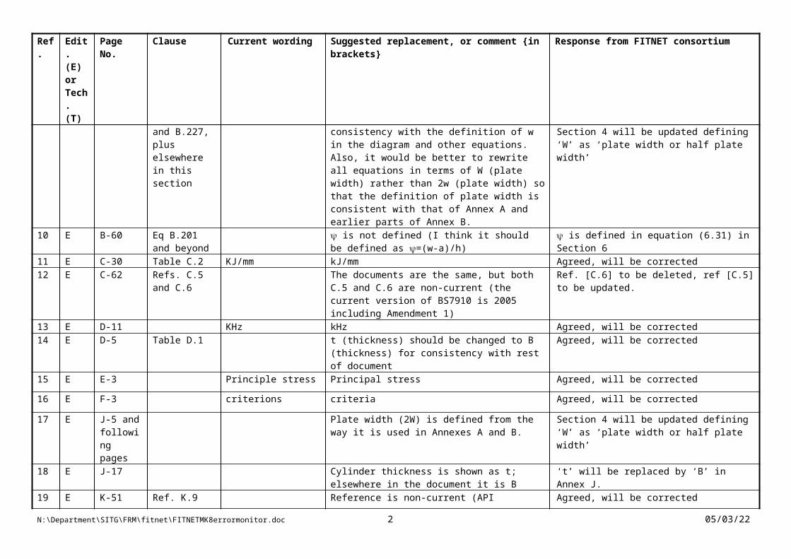
W should be replaced by w for consistency with the definition of w in the diagram and other equations. Also, it would be better to rewrite all equations in terms of W (plate width) rather than 2w (plate width) so that the definition of plate width is consistent with that of Annex A and earlier parts of Annex B.
‘w’ will be replaced by ‘W’ and Section 4 will be updated defining ‘W’ as ‘plate width or half plate width’
10 E B-60 Eq B.201 and beyond
is not defined (I think it should be defined as =(w-a)/h)
is defined in equation (6.31) in Section 6
11 E C-30 Table C.2 KJ/mm kJ/mm Agreed, will be corrected12 E C-62 Refs. C.5 and
C.6The documents are the same, but both C.5 and C.6 are non-current (the current version of BS7910 is 2005 including Amendment 1)
Ref. [C.6] to be deleted, ref [C.5] to be updated.
N:\Department\SITG\FRM\fitnet\FITNETMK8errormonitor.doc 1 07/05/23
Ref.
Edit. (E) or Tech. (T)
Page No. Clause Current wording Suggested replacement, or comment {in brackets}
Response from FITNET consortium
13 E D-11 KHz kHz Agreed, will be corrected14 E D-5 Table D.1 t (thickness) should be changed to B (thickness)
for consistency with rest of document Agreed, will be corrected
15 E E-3 Principle stress Principal stress Agreed, will be corrected
16 E F-3 criterions criteria Agreed, will be corrected
17 E J-5 and following pages
Plate width (2W) is defined from the way it is used in Annexes A and B.
Section 4 will be updated defining ‘W’ as ‘plate width or half plate width’
18 E J-17 Cylinder thickness is shown as t; elsewhere in the document it is B
‘t’ will be replaced by ‘B’ in Annex J.
19 E K-51 Ref. K.9 Reference is non-current (API 579-1/ASME FFS-1 is now current)
Agreed, will be corrected
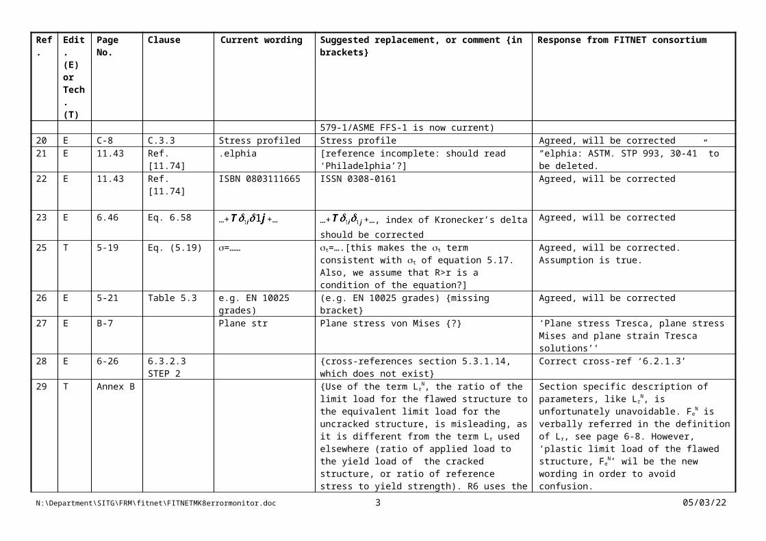
20 E C-8 C.3.3 Stress profiled Stress profile Agreed, will be corrected21 E 11.43 Ref. [11.74] .elphia [reference incomplete: should read ‘Philadelphia’?] “elphia: ASTM. STP 993, 30-41” to be deleted.22 E 11.43 Ref. [11.74] ISBN 0803111665 ISSN 0308-0161 Agreed, will be corrected
23 E 6.46 Eq. 6.58 …+ +… …+ +…, index of Kronecker’s delta should be corrected
Agreed, will be corrected
25 T 5-19 Eq. (5.19) =…… t=….[this makes the t term consistent with t of equation 5.17. Also, we assume that R>r is a condition of the equation?]
Agreed, will be corrected. Assumption is true.
26 E 5-21 Table 5.3 e.g. EN 10025 grades)
(e.g. EN 10025 grades) {missing bracket} Agreed, will be corrected
27 E B-7 Plane str Plane stress von Mises {?} ‘Plane stress Tresca, plane stress Mises and plane strain Tresca solutions’’
28 E 6-26 6.3.2.3 STEP 2
{cross-references section 5.3.1.14, which does not exist}
Correct cross-ref ‘6.2.1.3’
29 T Annex B {Use of the term LrN, the ratio of the limit load for
the flawed structure to the equivalent limit load for the uncracked structure, is misleading, as it is different from the term Lr used elsewhere (ratio of applied load to the yield load of the cracked
Section specific description of parameters, like Lr
N, is unfortunately unavoidable. FeN is verbally
referred in the definition of Lr, see page 6-8. However, ‘plastic limit load of the flawed structure, Fe
N’ wil be the new wording in order
N:\Department\SITG\FRM\fitnet\FITNETMK8errormonitor.doc 2 07/05/23
Ref.
Edit. (E) or Tech. (T)
Page No. Clause Current wording Suggested replacement, or comment {in brackets}
Response from FITNET consortium
structure, or ratio of reference stress to yield strength). R6 uses the term nL for the same parameter. Also, terms such as Fe
N are used only in this Annex, not elsewhere in the document, where driving force tends to be expressed in terms of stress.
to avoid confusion.
30 E B-7 {equation label for (B.1) is missing (B.1) exists in the word doc. – pdf conversion error.Attention will be paid…
31 E B-7 Just below heading
Applicable clause(s): (B.1)
Applicable clause(s): (B.1), (B.2) Agreed, will be corrected
32 E B-60 Eq (B.201) {equations are given for 0<=psi<=1.43 and for 1.43<=psi, which is potentially ambiguous for psi=1.43 (same ambiguity comes up elsewhere in annex, eg (B.211)). Also, psi>=1.43 would be more intuitive than 1.43<=psi
0<=psi<=1.43 and psi>1.43 is the correct formulation. Intervals of piecewise defined functions in B.9 will be controlled and corrected.
33 E B-60 Eq (B.201) {w, h and psi are not defined in the nomenclature at the start of the annex (although w and h are defined in the sketch)}
Nomenclature at the beginning of this section will be omitted and Section 4 will be updated accordingly.
34* E/T A-10 Eq. A.13 {1-(a/c)24} {the first M3 term is wrong. The ‘power 24’ term should be outside the curly brackets, ie {1-(a/c)}24]}
Agreed, will be corrected
35 E A-6, A-9, A-21
[W not shown on sketches}. Some of the solutions are for infinite plates, and require modification to allow for finite width, ie the fW term, so W should be defined for all such cases
Agreed, will be corrected
36 E A-6 {B is used both for plate thickness and for a specific location (points A and B)
A and B will be replaced by ‘s1’ and ‘s2’
37 E A-17 Eq [A.20] a/t a/B {terminology should be consistent with BS7910}
Agreed, will be corrected accordingly.
38* T 6-24 Eq. 6.14 {the power signs should be -½, not ½, in order to produce a sensible FAD which also agrees with the SINTAP and MK7 FAD equations}
Agreed, will be corrected as in tables 6.4, see below…
39 E 4-7 Top of page {no symbol associated with the description ‘plane-strain fracture toughness for quasi-static loading rates (MPa√m)’}
KIc, former definition from BS 7448, latter from ASTM 399-06
40* T 6-24 Eqns (6.17) {the power signs should be -½, not ½, in order to Agreed, will be corrected as in tables 6.4, see
N:\Department\SITG\FRM\fitnet\FITNETMK8errormonitor.doc 3 07/05/23

Ref.
Edit. (E) or Tech. (T)
Page No. Clause Current wording Suggested replacement, or comment {in brackets}
Response from FITNET consortium
and (6.18) produce a sensible FAD which also agrees with the SINTAP and MK7 FAD equations}
below…
41 T/E Annex A {any amendments made to Annex M of BS7910 (which is currently under review) after the publication of FITNET MK8 should also be made to Annex A of FITNET. A list of corrections can be provided on request.}
The list is highly appreciated.
42 E 1-2 Figure 1.1 'Type of thoughness data'
'Type of toughness data' Agreed, will be corrected
43 E 1-3 Figure 1.2 FCC FCG Agreed, will be corrected
44 E 1-5 Figure 1.3 {the flow diagram has part of an arrow returning to a previous step missing}
Agreed, will be corrected together with Figure 8.1
45 E 3-3 Section 3.4 {the inverted commas around 'Mismatch Option' are incorrect}
Agreed, will be corrected
46 E 3-3 Section 3.5 'less unlikely' 'less likely' {sentence beginning 'The slope of the R-curve . .'}
Agreed, will be corrected
47 E 5-37 5.10 'Fracture thougness data available'
‘…toughness….’ Agreed, will be corrected
48 E 3-3 3.5 ‘dependant’ ‘dependent’ {it would be even better to say ‘The shape of the R-curve furthermore depends on …..’}
Agreed. ‘The shape of the R-curve futhermore depends on …’
49 E 6-30 Eq (6.23) {Re is shown as the denominator for both equations and is defined under eq (6.21). However, it would be clearer if these were shown as Re
W and ReB
Agreed, will be corrected as in table 6.5 below
50 E 6-31 Eq. (6.29) {this equation is not referred to in the text eg 6.3.3.4a) and b). Is this an error?
To be referred, p. 6-29, 6.3.3.4, (b) …(6.25), (6.29), and (6.30)…)
51 E 6-24 All equations {The and signs are used too freely, eg (6.14) and (6.15) both give values for Lr=1
Will be corrected as in table 6.4, see below
52 E B-4 {Re is defined as yield stress; elsewhere (eg 4-12) it is defined as a general term for yield or proof strength. The latter is a better definition.}
Agreed, Re will denote yield or proof strength
53 E 6-24 Footer is wrong, reads 2007 Agreed, will be corrected
N:\Department\SITG\FRM\fitnet\FITNETMK8errormonitor.doc 4 07/05/23

Ref.
Edit. (E) or Tech. (T)
Page No. Clause Current wording Suggested replacement, or comment {in brackets}
Response from FITNET consortium
54 E 6-31 (6.26) and elsewhere
Feff is undefined Feff should have been FeH, will be corrected as in table 6.6, see below…
55 E 6-31 Eq (6.26) Lambda is defined for discontinuous yielding only (eq 6.18), but the ‘tensile data’ column refers to base and weld metal being continuous.
See table 6.6 below…
56 E 4-23 {Rp is used to denote both proof strength and cyclic plastic zone size. It should be unambiguous}
Rp denotes only proof strengthrp denotes cyclic plastic zoneWill be corrected…
57 E 6-31 Eq. (6.26) {Fbeff should presumably read FB
eff to be consistent with the earlier term FB
eff See response to comment 54, Will be corrected as in table 6.6, see below…
58 E/T 6-31 Eq. (6.26) {‘A’ under the column ‘Definitions’ is undefined} ‘A’ to be deleted…See table 6.6 below
59 E 6-31 Eq. (6.26) {Are FpM and Fe
M different? Are they calculated by putting the appropriate value of Rp or Re into equations B.2, B.3 etc?
Yes, they are different. FpM by putting Rp, Fe
M by putting Re
60* T {The graph 1 below shows an Option 1 FAD for a continuously yielding Al alloy, as per equations 6.14 and 6.15 of FITNET MK8. I had always assumed that Option 1 of FITNET was the same as Option 1 of R6, ie that we use the same equation for all values of Lr, truncating the distribution at Lr,max. However, from Table 6.4 of FITNET, the implication is that you switch from eq. 6.14 to 6.15 at Lr=1, which causes a discontinuity in the graph. Shouldn’t eq. (6.15) be for DISCONTINUOUS yielding only?}
FITNET Option 1 = Approximate Option 2 of R6. See graph 2. See tables 6.4 below…
61* T 6-30 Eq (6.25) {does not work for undermatched welds, as it gives a very low value of Lr,max. Seems to originate from equation I.4.10 of SINTAP, but eq. III.4.31 of SINTAP and equation III.8.2.3 of R6 contradict it.}
To be corrected as in table 6.5…
62 E 5-18 5.4.3.1, para 2 ‘…ReH and ReH…’ ‘…ReL and ReH…’ Agree
63 E 12-22 12.5.3 {ref. nos are incorrect. Should start with [12.46] for compatibility with section 12.4, but the cross-references in this section start at [12.44]}
Agree
64 E 12-22 12.5.3 ‘.. one of the most ‘.. one of the best-developed local criteria…’ (?) AgreeN:\Department\SITG\FRM\fitnet\FITNETMK8errormonitor.doc 5 07/05/23

Ref.
Edit. (E) or Tech. (T)
Page No. Clause Current wording Suggested replacement, or comment {in brackets}
Response from FITNET consortium
extended local criteria..’
65 E 12-22 12.5.3 ‘..greater that the material strength..’
‘..greater than the material strength..’ Agree
66 E 12-24 12.5.5 ‘… first term in William’s series…’
‘… first term in Williams’ series…’ Agree
67 T 12-23 & 23
12.5.3 Term ρ appears in formulas on these pages. From context it is thought that this ρ may be something different (like radius?) from the plasticity correction factor indicated in the symbols list.
Also, on page 6-11: “ a method for calculating ρ is given in 6.4.3. “ but I can’t find it. 6.4.3 seems to point at annex J and K, but these also contain no clear info to me.
To discuss with author
Definition of (and V) were inadvertently omitted from MK8, having been incorporated in earlier editions. See item 76
68 T 6-50, 51&53
6.4.3.3.4.3, 4,5
Formula (6.72) is put into (6.74) to make (6.75),(6.76), but the power k becomes a power m? m is given in the list of symbols, but seems to be something else here (weibull parameter)?
k should read m, in equation 6.72 and the following paragraphs on the same page. M is also used as a different parameter, but the difference should be clear.
69 HGP comment on crack arrest in R6 also applicable to FITNET
Will be addressed by R6 panel
70 E 7-76 Ref {7.17] NASGO NASGRO Agree
71* T 6-30 and 6-31
Equations (6.23), (6.25), (6.27), (6.29)
Several errors in equations Whole of tables 6.5 and 6.6 have been replaced (see end of document) to correct errors
72 T Annex D {extensive comments e-mailed from Colin Bird and Kenneth Macdonald, which will be incorporated into the revision of BS7910, Annex V}
73 T 9-19 equation (9.4) {The denominator is (D0-t) rather than (D0-2t)} The different design codes use different equations. E.g. B31.4 and 31.8 use (OD), ASME div 1 use (ID+1.2t)=(OD-0.8t), EN 13445-3 use (OD-t). We decided to use the mean diameter (thin shell theory).
N:\Department\SITG\FRM\fitnet\FITNETMK8errormonitor.doc 6 07/05/23

Ref.
Edit. (E) or Tech. (T)
Page No. Clause Current wording Suggested replacement, or comment {in brackets}
Response from FITNET consortium
74 E D-5 D.2 principals principles Agree
75 T {e-mail of 7 April 2010 regarding use of Q} FITNET does not contain detailed Q solutions, although it cross-references various sources; users may have to carry out their own FEA to use the Q approach
76 T {e-mail of 12 May 2010 regarding use of and v factors}
Definition of (and V) were inadvertently omitted from MK8, having been incorporated in earlier editions. A new section 6.2.1.2.3 (Procedure for the evaluation of ) and 6.2.1.3.5 (Procedure for the evaluation of V) will be added and correctly cross-referenced in section 6.2.1.3.1 and 6.2.1.3.2. Copy of text is given below, but numbering of clauses, tables etc will have to change to accommodate it.
77 E 11.4 onwards {cross-references from section 11.4 to end of section 11 are incorrect}
To be corrected
78 E 7-54 7.3.5, last para {In ‘porosity and inclusions’ section, cross-reference to ‘Annex K’ should read ‘Annex G’}
79* T 6-29 6.3.3.4 (a)….In this case, f(Lr) is based upon equations (6.14), (6.15), (6.16) and (6.18)…
(a)….In this case, f(Lr) is based upon equations (6.14), (6.18d), (6.18b) and (6.18c)…
A revised table 6.4b is given below
80* T 6-29 6.3.3.4 (b)….In this case, f(Lr) is based upon equations (6.14), (6.15), (6.16) and (6.18)…
(b)….In this case, f(Lr) is based upon equations (6.14), (6.18d), (6.18b) and (6.18c)…
A revised table 6.4b is given below
81 E {errors notified to IIW in connection with the IIW FFS document may also be applicable to FITNET, since the IIW document was based on FITNET}
82 New sections 6.3.3.and 6.4.3 and Table 6.4 supplied on 9 June 2010
N:\Department\SITG\FRM\fitnet\FITNETMK8errormonitor.doc 7 07/05/23

Ref.
Edit. (E) or Tech. (T)
Page No. Clause Current wording Suggested replacement, or comment {in brackets}
Response from FITNET consortium
* denotes potentially serious errors
N:\Department\SITG\FRM\fitnet\FITNETMK8errormonitor.doc 8 07/05/23

Graph 1
N:\Department\SITG\FRM\fitnet\FITNETMK8errormonitor.doc 9 07/05/23
FITNET Option 1 FAD
0.000
0.200
0.400
0.600
0.800
1.000
1.200
0 1 2 3
Lr
Kr
eq. (6.14)
eq. (6.15)
eq. (6.17)
R6 Option 1

Graph 2
FADs of Option 1,for continuous yielding, steel, (YS=500 MPa, UTS=600 MPa, E=210GPa,)for discontinuous yielding, steel, (YS=526 MPa, UTS=600 MPa, E=210GPa,)
N:\Department\SITG\FRM\fitnet\FITNETMK8errormonitor.doc 10 07/05/23

Table 6.4 a) Continuous yielding
Eqn. Nr. Formula for Definitions Tensile Data Range of
(6.14) is Young’s modulus
is proof strength in MPa
Continuous Yielding
(6.15) is calculated by setting in equation
(6.14) is an estimate of the strain hardening exponent
given by
is , in MPa, for continuously yielding material
is the material’s ultimate tensile strength in MPa
Continuous Yielding
(6.16) Continuous Yielding
N:\Department\SITG\FRM\fitnet\FITNETMK8errormonitor.doc 11 07/05/23

Table 6.4 b) Discontinuous yielding
Eqn. Nr. Formula for Definitions Tensile Data Range of
(6.17) Discontinuous Yielding
(6.18)a
is the lower yield strain given by
is the material’s upper yield strength or limit of proportionality.
Discontinuous Yielding in both constituents
(6.18)b is adopted from equation (6.18)a
is an estimate of the strain hardening exponent
given by
is yield strength, either ReL or , in MPa, for discontinuously yielding materials.
is the material’s ultimate tensile strength in MPa
Discontinuous Yielding
(6.18)c Discontinuous Yielding
(6.18)d If one of the constituents shows discontinuous yielding, replaces 6.18a
N:\Department\SITG\FRM\fitnet\FITNETMK8errormonitor.doc 12 07/05/23

Table 6.5
Eqn. Nr. Formulae Definitions Tensile Data
(6.21) is either , , or , for
weld, , or base metal, , depending on material
Continuous or Discontinuous
(6.22) is the mismatch yield limit load
is the base metal yield limit load
defined at
Continuous or Discontinuous
(6.23)Both Base and Weld Metal continuous
(6.24)Continuous or Discontinuous
(6.25)Text deleted Continuous or Discontinuous
N:\Department\SITG\FRM\fitnet\FITNETMK8errormonitor.doc 13 07/05/23

Table 6.6
Eqn. Nr. Formulae Definitions Tensile data Eq. for
(6.26) Both Base and Weld Metal Discontinuous
(6.18)
(6.27) Base Metal continuous
Weld Metal discontinuous
(6.14)
(6.28) Base Metal continuous
Weld Metal discontinuous
(6.18)
(6.29) Weld Metal continuous Base Metal discontinuous
(6.14)
(6.30) Weld Metal continuous Base Metal discontinuous
(6.18)
N:\Department\SITG\FRM\fitnet\FITNETMK8errormonitor.doc 14 07/05/23

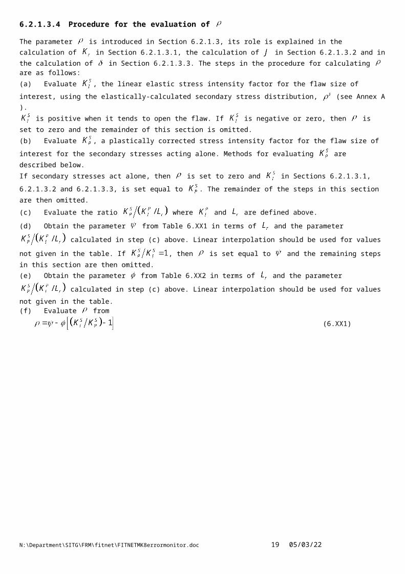
6.2.1.3.4 Procedure for the evaluation of
The parameter is introduced in Section 6.2.1.3, its role is explained in the calculation of in Section 6.2.1.3.1, the calculation of in Section 6.2.1.3.2 and in the calculation of in Section 6.2.1.3.3. The steps in the procedure for calculating are as follows:(a) Evaluate , the linear elastic stress intensity factor for the flaw size of interest, using the elastically-calculated
secondary stress distribution, (see Annex A ).
is positive when it tends to open the flaw. If is negative or zero, then is set to zero and the remainder of this section is omitted.(b) Evaluate , a plastically corrected stress intensity factor for the flaw size of interest for the secondary stresses acting
alone. Methods for evaluating are described below.
If secondary stresses act alone, then is set to zero and in Sections 6.2.1.3.1, 6.2.1.3.2 and 6.2.1.3.3, is set equal to . The remainder of the steps in this section are then omitted.
(c) Evaluate the ratio where and are defined above.
(d) Obtain the parameter from Table 6.XX1 in terms of and the parameter calculated in step (c)
above. Linear interpolation should be used for values not given in the table. If , then is set equal to and the remaining steps in this section are then omitted.
(e) Obtain the parameter from Table 6.XX2 in terms of and the parameter calculated in step (c)
above. Linear interpolation should be used for values not given in the table.(f) Evaluate from
(6.XX1)
N:\Department\SITG\FRM\fitnet\FITNETMK8errormonitor.doc 15 07/05/23

Table 6.XX1 – Values of as a function of and
0 0.5 1.0 1.5 2.0 2.5 3.0 3.5 4.0 4.5 5.0
0 0 0 0 0 0 0 0 0 0 0 0
0.1 0 0.020 0.043 0.063 0.074 0.081 0.086 0.090 0.095 0.100 0.107
0.2 0 0.028 0.052 0.076 0.091 0.100 0.107 0.113 0.120 0.127 0.137
0.3 0 0.033 0.057 0.085 0.102 0.114 0.122 0.130 0.138 0.147 0.160
0.4 0 0.037 0.064 0.094 0.113 0.126 0.136 0.145 0.156 0.167 0.182
0.5 0 0.043 0.074 0.105 0.124 0.138 0.149 0.160 0.172 0.185 0.201
0.6 0 0.051 0.085 0.114 0.133 0.147 0.159 0.170 0.184 0.200 0.215
0.7 0 0.058 0.091 0.117 0.134 0.147 0.158 0.171 0.186 0.202 0.214
0.8 0 0.057 0.085 0.105 0.119 0.130 0.141 0.155 0.169 0.182 0.190
0.9 0 0.043 0.060 0.073 0.082 0.090 0.101 0.113 0.123 0.129 0.132
1.0 0 0.016 0.019 0.022 0.025 0.031 0.039 0.043 0.044 0.041 0.033
1.1 0 -0.013 -0.025 -0.033 -0.036 -0.037 -0.042 -0.050 -0.061 -0.073 -0.084
1.2 0 -0.034 -0.058 -0.075 -0.090 -0.106 -0.122 -0.137 -0.151 -0.164 -0.175
1.3 0 -0.043 -0.075 -0.102 -0.126 -0.147 -0.166 -0.181 -0.196 -0.209 -0.220
1.4 0 -0.044 -0.080 -0.109 -0.134 -0.155 -0.173 -0.189 -0.203 -0.215 -0.227
1.5 0 -0.041 -0.075 -0.103 -0.127 -0.147 -0.164 -0.180 -0.194 -0.206 -0.217
1.6 0 -0.037 -0.069 -0.095 -0.117 -0.136 -0.153 -0.168 -0.181 -0.194 -0.205
1.7 0 -0.033 -0.062 -0.086 -0.107 -0.125 -0.141 -0.155 -0.168 -0.180 -0.191
1.8 0 -0.030 -0.055 -0.077 -0.096 -0.114 -0.129 -0.142 -0.155 -0.166 -0.177
1.9 0 -0.026 -0.049 -0.069 -0.086 -0.102 -0.116 -0.129 -0.141 -0.152 -0.162
2.0 0 -0.023 -0.043 -0.061 -0.076 -0.091 -0.104 -0.116 -0.126 -0.137 -0.146
N:\Department\SITG\FRM\fitnet\FITNETMK8errormonitor.doc 16 07/05/23

Table 6.XX2 – Values of as a function of and
0 0.5 1.0 1.5 2.0 2.5 3.0 3.5 4.0 4.5 5.0
0 1.0 1.0 1.0 1.0 1.0 1.0 1.0 1.0 1.0 1.0
0.1 0 0.815 0.869 0.877 0.880 0.882 0.883 0.883 0.882 0.879 0.874
0.2 0 0.690 0.786 0.810 0.821 0.828 0.832 0.833 0.833 0.831 0.825
0.3 0 0.596 0.715 0.752 0.769 0.780 0.786 0.789 0.789 0.787 0.780
0.4 0 0.521 0.651 0.696 0.718 0.732 0.740 0.744 0.745 0.743 0.735
0.5 0 0.457 0.589 0.640 0.666 0.683 0.693 0.698 0.698 0.695 0.688
0.6 0 0.399 0.528 0.582 0.612 0.631 0.642 0.647 0.648 0.644 0.638
0.7 0 0.344 0.466 0.522 0.554 0.575 0.587 0.593 0.593 0.589 0.587
0.8 0 0.290 0.403 0.460 0.493 0.516 0.528 0.533 0.534 0.534 0.535
0.9 0 0.236 0.339 0.395 0.430 0.452 0.464 0.470 0.475 0.480 0.486
1.0 0 0.185 0.276 0.330 0.364 0.386 0.400 0.411 0.423 0.435 0.449
1.1 0 0.139 0.218 0.269 0.302 0.326 0.347 0.367 0.387 0.406 0.423
1.2 0 0.104 0.172 0.219 0.256 0.287 0.315 0.340 0.362 0.382 0.399
1.3 0 0.082 0.142 0.190 0.229 0.263 0.291 0.316 0.338 0.357 0.375
1.4 0 0.070 0.126 0.171 0.209 0.241 0.269 0.293 0.314 0.333 0.350
1.5 0 0.062 0.112 0.155 0.190 0.220 0.247 0.270 0.290 0.309 0.325
1.6 0 0.055 0.100 0.139 0.172 0.200 0.225 0.247 0.267 0.285 0.301
1.7 0 0.048 0.089 0.124 0.154 0.181 0.204 0.224 0.243 0.260 0.276
1.8 0 0.042 0.078 0.110 0.137 0.161 0.183 0.202 0.220 0.236 0.250
1.9 0 0.036 0.068 0.096 0.120 0.142 0.162 0.180 0.196 0.211 0.225
2.0 0 0.031 0.058 0.082 0.104 0.124 0.141 0.157 0.172 0.186 0.198
N:\Department\SITG\FRM\fitnet\FITNETMK8errormonitor.doc 17 07/05/23

Advice on Calculating
Step (b) above requires the calculation of an effective stress intensity factor, , for the secondary stresses acting alone. Here, four methods are given in order of accuracy and reducing complexity.1. Cracked Body Inelastic AnalysisThe most detailed and accurate approach for calculating is to perform an inelastic analysis of the cracked body to obtain a
value of the -integral for the secondary loading alone. Then
(6.XX2)
where in plane stress and in plane strain. Note, the value of is specific to the material stress-strain
curve and the flaw size used as input to the inelastic analysis. Therefore, for example, inelastic calculations will need to be repeated for a range of flaw sizes with this option if a limiting flaw size is being determined.2. Uncracked Body Inelastic AnalysisCompared to cracked body inelastic analysis, uncracked body inelastic analyses are quicker and cheaper to perform. One inelastic analysis may then be used to evaluate for a range of flaw sizes of interest as set out below.
It is assumed that the stress and mechanical strains , and across the plane of the flaw have been determined from an elastic-plastic analysis of the uncracked body. Here the y-axis is normal to the plane of the flaw and x, z are in-plane. The strains are the mechanical components, that is, any strain due to uniform thermal expansion has been subtracted from the total strain values. In steps (iii) and (iv), effective flaw sizes are calculated. These flaw sizes may exceed the section thickness in some cases. The calculated values should be used in all cases in step (v).(i) Determine an effective stress intensity factor from the uncracked-body stress normal to the crack plane.
(ii) Determine an effective stress intensity factor from the 'stress' normal to the crack plane defined in terms of
the elastic-plastic, uncracked-body mechanical strains as if the material response were linear elastic. Specifically, is given by
(6.XX3)
(iii) Define an effective crack size from
(6.XX4)
where = 1, 3 for plane stress or plane strain, respectively.
(iv) Define an effective crack size from
(6.XX5)
where = 1, 3 in plane stress or plane strain, respectively.
(v) Evaluate from
(6.XX6)
3. Estimates from Plastic Zone Size CorrectionIn the absence of an elastic-plastic analysis, a conservative estimate of may be obtained from the linear stress intensity factor
as
(6.XX7)
where
(6.XX8)
N:\Department\SITG\FRM\fitnet\FITNETMK8errormonitor.doc 18 07/05/23
where = 1 in plane stress and = 3 in plane strain. This estimate clearly leads to and may be over-conservative for elastically calculated secondary stresses which are not much greater than yield. However, it does provide a simple approximation without the need for inelastic analysis. Note, may exceed the section thickness in some cases. Where is expected to be
less than , then this estimate should not be used; instead, either the simple elastic estimate below should be used or one of the methods described above can be used to quantify the reduction in effective stress intensity factor.4. Elastic EstimateThe simplest approach is to set
(6.XX9)
This direct use of the elastic calculation is likely to be adequate when the secondary stresses are low compared to the yield stress and elastic follow-up is judged not to be significant. For large secondary stresses, particularly those which are non-uniform in the region of the flaw, plastic redistribution of stress is likely to be important and the direct use of elastic calculations is likely to be over-conservative.
N:\Department\SITG\FRM\fitnet\FITNETMK8errormonitor.doc 19 07/05/23

6.2.1.3.5 Procedure for the evaluation of
The methodology set out above follows that in R6 as discussed in [2.1]. Further advice on the use of finite-element analysis to calculate is contained in R6. An alternative approach to the definition of is given in Section 6.2.1.3.1 as
(6.X10)
The parameter plays a similar role to the parameter in covering the effects of plasticity on secondary stresses. This definition of is equivalent to that using with taking an initial value for given by
(6.X11)
and, for ,
(6.X12)
may also be used in the same way when performing a CDF analysis using the equations given in Sections 6.2.1.3.2 or 6.2.1.3.3.Further discussion of the use of is contained in [2.1]. Experimental and numerical validation of the approach adopted here, or the equivalent approach, is also discussed in [2.1]. While the methods proposed are well validated this is an area where further work may lead to some simplification and potentially to reduced conservatism.
N:\Department\SITG\FRM\fitnet\FITNETMK8errormonitor.doc 20 07/05/23