CLAUSE NO. TECHNICAL · PDF file8 Standard : ANSI C 96.1 for Thermocouple and ASME PTC-19.3...
101
CLAUSE NO. TECHNICAL REQUIREMENTS MOUDA STPP-II (2x660MW) / SOLAPUR STPP (2 x 660MW) / NABINAGAR STPP (3x 660MW) / MEJA TPP-I (2 x 660MW) / RAGHUNATHPUR TPP PHASE-II (2 x660MW) STEAM GENERATOR PACKAGE TECHNICAL SPECIFICATION SECTION-VI BID DOC NO.: CS-9575/ 9571/ 0370/ 0360/ 9586-102-2 PART - B SUB-SECTION-IV I-4 (MEASURING INSTRUMENTATION) PAGE 5 OF 14 7 Accessories : Thermo well (as specified below) and shall be spring loaded for positive contacts with the well. 8 Standard : ANSI C 96.1 for Thermocouple and ASME PTC- 19.3 for Thermo-well. 3.02.00 Resistance Temperature Detector (RTD) --------------------------------------------------------------------------------------------------------------------------- Sr. No. Features Essential/Minimum Requirements --------------------------------------------------------------------------------------------------------------------------- 1 Type of RTD. : Four wire, Pt-100 (100 Ohms resistance at zero degree Centigrade). 2 No. of element : Duplex 3 Housing/Head : IP-55/Diecast Aluminium. Plug in connectors are to be provided for external signal cable connection. 4 Sheathing of RTD : Metal sheathed, ceramic packed 5 Calibration and accuracy : As per DIN-43760 Class-A for RTD 6 Characteristic : Linear with respect to temp, within ±1/2 percent of top range value. 7 Accessories : Thermo well (as specified below) and shall be spring loaded for positive contacts with the well. 8 Standard : DIN-43760 for RTD and ASME PTC-19.3 for Thermo-well. -------------------------------------------------------------------------------------------------------------------------- 3.03.00 Metal Temperature Thermocouples Measuring Medium Metal Temperature Material of Thermocouple. Chromel Alumel Type K Type of Thermocouple Duplex with separate hot junctions, ungrounded Insulation Mineral Insulation Magnesium Oxide. Thermocouple wire gauge 16 AWG Protective sheath SS 321 Protective sheath dia 8 mm O.D Characteristics of Special limits of error as in ANSI Thermocouple thermocouple MC 96.01.1975 Mounting accessories 1/2" BSP SS sliding end connector, weld pad, clamps of heat resistant steel SS310.
Transcript of CLAUSE NO. TECHNICAL · PDF file8 Standard : ANSI C 96.1 for Thermocouple and ASME PTC-19.3...

CLAUSE NO. TECHNICAL REQUIREMENTS
MOUDA STPP-II (2x660MW) / SOLAPUR STPP (2 x 660MW) / NABINAGAR STPP (3x 660MW) /
MEJA TPP-I (2 x 660MW) / RAGHUNATHPUR TPP PHASE-II (2 x660MW)
STEAM GENERATOR PACKAGE
TECHNICAL SPECIFICATION SECTION-VI
BID DOC NO.: CS-9575/ 9571/ 0370/ 0360/ 9586-102-2
PART - B SUB-SECTION-IV I-4 (MEASURING
INSTRUMENTATION) PAGE 5 OF 14
7 Accessories : Thermo well (as specified below) and shall be spring loaded for positive contacts with the well.
8 Standard : ANSI C 96.1 for Thermocouple and ASME PTC-19.3 for Thermo-well.
3.02.00 Resistance Temperature Detector (RTD)
--------------------------------------------------------------------------------------------------------------------------- Sr. No. Features Essential/Minimum Requirements ---------------------------------------------------------------------------------------------------------------------------
1 Type of RTD. : Four wire, Pt-100 (100 Ohms resistance at zero degree Centigrade).
2 No. of element : Duplex
3 Housing/Head : IP-55/Diecast Aluminium. Plug in connectors are to be provided for external signal cable connection.
4 Sheathing of RTD : Metal sheathed, ceramic packed
5 Calibration and accuracy : As per DIN-43760 Class-A for RTD
6 Characteristic : Linear with respect to temp, within ±1/2 percent of top range value.
7 Accessories : Thermo well (as specified below) and shall be spring loaded for positive contacts with the well.
8 Standard : DIN-43760 for RTD and ASME PTC-19.3 for Thermo-well.
--------------------------------------------------------------------------------------------------------------------------
3.03.00 Metal Temperature Thermocouples
Measuring Medium Metal Temperature
Material of Thermocouple. Chromel Alumel Type K
Type of Thermocouple Duplex with separate hot junctions, ungrounded
Insulation Mineral Insulation Magnesium Oxide.
Thermocouple wire gauge 16 AWG
Protective sheath SS 321
Protective sheath dia 8 mm O.D
Characteristics of Special limits of error as in ANSI Thermocouple thermocouple MC 96.01.1975
Mounting accessories 1/2" BSP SS sliding end connector, weld pad, clamps of heat resistant steel SS310.

CLAUSE NO. TECHNICAL REQUIREMENTS
MOUDA STPP-II (2x660MW) / SOLAPUR STPP (2 x 660MW) / NABINAGAR STPP (3x 660MW) /
MEJA TPP-I (2 x 660MW) / RAGHUNATHPUR TPP PHASE-II (2 x660MW)
STEAM GENERATOR PACKAGE
TECHNICAL SPECIFICATION SECTION-VI
BID DOC NO.: CS-9575/ 9571/ 0370/ 0360/ 9586-102-2
PART - B SUB-SECTION-IV I-4 (MEASURING
INSTRUMENTATION) PAGE 6 OF 14
Cold end sealing SS pot weal with colour coded PTFE headed sleeve Insulated flexible tails. Sealing compound- Epoxy resin.
Minimum bending radius 30 mm
Length of T/C 30 Mtr. (minimum)
3.04.00 Thermo well (for all process temp. elements)
(a) Shall be one piece solid bored type of 315 SS of step-less tapered design. (As per ASME PTC 19.3 1974)
(b) For Mill classifier outlet long life solid sintered tungsten carbide material of high abrasion resistance shall be provided.
(c) For Air & Flue gas 316 SS protecting tube with welded cap. (However contractor shall provide better material for Flue gas service if require based on the specify boiler design parameters).
(d) For furnace zone, impervious ceramic protecting tube of suitable material along with Incoloy supporting tubes and adjustable flanges.
4.00.00 TEMPERATURE TRANSMITTER
Following types of 2-wire temperature transmitter (directly powered from 4-20mA input cards of DDCMIS) shall be provided. The temperature transmitter shall be fully compatible with thermocouples and RTDs being provided by the contractor. Temperature compensation of the thermocouples shall be performed in the temperature transmitter itself.
a. Single Input Head mounted Temperature Transmitter
These shall be suitable for mounting in the head of temperature element itself. The protection class of head of thermo well along with its plug-in connector shall be min. IP65.
b. Single Input DIN-rail mounted Temperature Transmitter
These shall be especially designed for DIN-rail mounting in JBs. The specifications of the JBs shall be same as indicated in Subsection-IV:I7(INST CABLE) with additional DIN-rails and IP 65 Protection class. This temperature transmitter shall be the ones which are specially designed for DIN-rail mounting with IP 20 protection class. These shall have terminals for input/output provided on front side when mounted on DIN-rail. Head mounted temperature transmitter with clamps to make it suitable for DIN-rail mounting shall not be acceptable under this category.
c. Dual-input Temperature Transmitter With Indicator:
The dual-input TTs shall be suitable for mounting in enclosures/racks and shall be provided with clamps. Indicator shall be provided with these transmitters. These transmitters shall have bump less change over facility to second sensor in case first sensor fails .This change-over is to be alarmed. Protection class shall be IP65 minimum.
CLAUSE NO. TECHNICAL REQUIREMENTS
MOUDA STPP-II (2x660MW) / SOLAPUR STPP (2 x 660MW) / NABINAGAR STPP (3x 660MW) /
MEJA TPP-I (2 x 660MW) / RAGHUNATHPUR TPP PHASE-II (2 x660MW)
STEAM GENERATOR PACKAGE
TECHNICAL SPECIFICATION SECTION-VI
BID DOC NO.: CS-9575/ 9571/ 0370/ 0360/ 9586-102-2
PART - B SUB-SECTION-IV I-4 (MEASURING
INSTRUMENTATION) PAGE 7 OF 14
d. Common requirements for each of the above type of temperature transmitters
Output : 2-wire (power supply from input card of Control System) with 4-20mA output with superimposed HART protocol signal.
Input : Same transmitter shall be capable to handle Pt-100 RTD , Thermocouples -K&R types (input type to be selectable at site through HART terminal)
Isolation : min. 500 V AC
EMC compatibility : as per EN 61326
Operating ambient : 0 to 85 deg C (without indicator) temperature 0 to 70 deg C (with indicator)
Power supply compatible with input module of Control System
Accessories Mounting arrangements including clamps etc.
Composite (a) For head mounted and DIN-rail mounted Accuracy types:
(Refer note 2 ) RTD =<0.4% of 0-250 deg C span T/C-K type =<0.4% of 0-600 deg C span T/C-R type =<0.4% of 0-1000 deg C span
CJC accuracy (for thermocouples) shall be =< 1 deg C
(b) For dual-input type:
RTD =<0.25% of 0-250 deg C span T/C-K type =<0.2% of 0-600 deg C span CJC accuracy (for thermocouples) shall be =< 1 deg C
------------------------------------------------------------------------------------------------------------
e. Field bus compatible temperature Transmitters (For Boiler Metal Temperature measurement applications)
Temperature transmitters of this category shall be field mounting type & shall be capable of withstanding operating ambient temperature upto 85 deg C. These modules shall be connected to DDCMIS through field bus such as Profibus, Foundation Field bus etc directly from the transmitter. Maximum Number of inputs per such temperature transmitter shall be eight. These shall be mounted in cabinets in non-AC areas.
As an alternate, these signals from temperature transmitters can be connected to DDCMIS through standard remote I/O modules of the DCS, in which case, the temperature transmitter signals will be acquired through 4-20mA input modules in the remote I/O cabinet for connecting to DDCMIS through remote I/O bus.

CLAUSE NO. TECHNICAL REQUIREMENTS
MOUDA STPP-II (2x660MW) / SOLAPUR STPP (2 x 660MW) / NABINAGAR STPP (3x 660MW) /
MEJA TPP-I (2 x 660MW) / RAGHUNATHPUR TPP PHASE-II (2 x660MW)
STEAM GENERATOR PACKAGE
TECHNICAL SPECIFICATION SECTION-VI
BID DOC NO.: CS-9575/ 9571/ 0370/ 0360/ 9586-102-2
PART - B SUB-SECTION-IV I-4 (MEASURING
INSTRUMENTATION) PAGE 8 OF 14
Notes:-( Common for a to be above):-
1. In case of failure (open or burn-out) of RTD/thermocouple, temp. Transmitter shall provide low temperature output.
2. Composite Accuracy is to be calculated as summation of all applicable accuracies of temp transmitter, for converting sensor input to output in 4-20 mA (e.g., basic accuracy, digital accuracy, D/A accuracy, etc.) and temperature effect on these accuracies at ambient temperature of 50 deg C, based on the figure/ formula given in the standard product catalogue for span as specified above for various types of Temperature Elements specified. All such accuracy/ temp effect figures in catalogue shall be first converted to deg C, and then percentage of this converted accuracy in specified span shall be calculated to compare with the specified composite accuracy figures.
5.00.00 SPECIFICATION FOR FLOW ELEMENTS
5.01.00 Orifice Plate
-------------------------------------------------------------------------------------------------------------------------- Features Essential/Minimum Requirements -------------------------------------------------------------------------------------------------------------------------- Type Concentric as per ASME PTC-19.5 (Part-II), ISA
RP-3.2, 1960 or BS-1042
Material 316 SS
Thickness 3 mm for main pipe diameter up to 300 mm and6 mm for main pipe dia above300 mm.
Material of branch pipe Same as main pipe
Root valve type Globe
Root valve material 316 SS
Root valve size 1 inch
Impulse pipe of same material Required up to root valve
Tappings Flanged weld neck. 3 pairs. of tapping.
Beta Ratio 0.34 to 0.7
Beta Ratio calculation to be Yes submitted
Assembly drg. and flow Vs Yes DP Curves
Accessories Root valves, flanges, Vent/drain hole (As required)
CLAUSE NO. TECHNICAL REQUIREMENTS
MOUDA STPP-II (2x660MW) / SOLAPUR STPP (2 x 660MW) / NABINAGAR STPP (3x 660MW) /
MEJA TPP-I (2 x 660MW) / RAGHUNATHPUR TPP PHASE-II (2 x660MW)
STEAM GENERATOR PACKAGE
TECHNICAL SPECIFICATION SECTION-VI
BID DOC NO.: CS-9575/ 9571/ 0370/ 0360/ 9586-102-2
PART - B SUB-SECTION-IV I-4 (MEASURING
INSTRUMENTATION) PAGE 9 OF 14
Contractor shall submit certified flow calculation and differential pressure vs. flow curves for each element for Employer's approval. Sizing calculation, precise flow calculation for all the flow elements, fabrication and assembly drawings and installation drawings shall be submitted for Employer's approval. One Flow element of each type shall be calibrated in the test laboratory for validation of computated flow calculations.
5.02.00 Flow Nozzle
--------------------------------------------------------------------------------------------------------------------------- Features Essential/Minimum Requirements ---------------------------------------------------------------------------------------------------------------------------
Type Long radius, welded type as per ASME PTC-19.5 (Part-III) or BS-1042
Material 316 SS
Thickness Suitable for intended application.
Material of branch pipe Same as main pipe
Root valve type Globe
Root valve material 316 SS
Root valve size 1 inch
Impulse pipe of same material Required up to root valve
Tapping D and D/2 (3 Nos. of tappings)
Beta Ratio Around 0.7
Beta Ratio calculation to be Yes submitted
Assembly drg. and flow Yes Vs DP Curves
Accessories Root valves, vent and drain hole. ---------------------------------------------------------------------------------------------------------------------------
Contractor shall submit certified flow calculation and differential pressure vs. flow curves for each element for Employer's approval. Sizing calculation, precise flow calculation for all the flow elements, fabrication and assembly drawings and installation drawings shall be submitted for Employer's approval. One Flow element of each type shall be calibrated in the test laboratory for validation of computed flow calculations.

CLAUSE NO. TECHNICAL REQUIREMENTS
MOUDA STPP-II (2x660MW) / SOLAPUR STPP (2 x 660MW) / NABINAGAR STPP (3x 660MW) /
MEJA TPP-I (2 x 660MW) / RAGHUNATHPUR TPP PHASE-II (2 x660MW)
STEAM GENERATOR PACKAGE
TECHNICAL SPECIFICATION SECTION-VI
BID DOC NO.: CS-9575/ 9571/ 0370/ 0360/ 9586-102-2
PART - B SUB-SECTION-IV I-4 (MEASURING
INSTRUMENTATION) PAGE 10 OF 14
6.00.00 SPECIFICATIONS FOR PR. GAUGE, D.P. GAUGE, TEMP. GAUGE AND LEVEL GAUGE.
--------------------------------------------------------------------------------------------------------------------------- Sl.No FEATURES ESSENTIAL/MINIMUM REQUIREMENTS --------------------------------------------------------------------------------------------------------------------------- Pr. Gauge/ DP Temperature Level Gauge Gauge/ Draught Gauge gauges --------------------------------------------------------------------------------------------------------------------------- 1 Sensing Bourdon for high Mercury in steel Tempered *toughened Element and pressure, Diaphragm/ for below 450°C Borosilicate gauge material Bellow for low pr. and inert gas glass steel armoured Of 316 SS actuated for reflex or transparent above 450°C of type. SS bulb and capillary.
2 Body material Die-cast aluminium Die-cast Forged carbon aluminium steel/304 SS 3 Dial size 150mm 150 mm Tubular covering entire range 4 End 1/2 inch NPT (M) 3/4" NPT (M) Process connection as connection per ASME PTC and drain/vent 15 NB 5 Accuracy ±1% of span ± 1% of span ± 2% 6 Scale Linear, 270° arc Linear, 270° arc Linear vertical graduated in graduated in °C metric units
7 Range Cover 125% of Cover 125% of Cover 125% of selection max. of scale max. of scale max. of scale 8 Over range Test pr. for the assembly shall be1.5 to the max. Design pr. at test 38°C. 9 Housing Weather and Weather and CS/304 SS leak
dust proof as dust proof as proof per IP-55 per IP-55 10 Zero/span Provided Provided -- adjustment
11 Identification Engraved with service legend or laminated phenolic name plate 12 Accessories Blow out disc, SS Thermowell Gasket for all siphon, snubber, KEL-F shield for pulsation dampener, transparent type vent chemical seal and drain valves of (if required by Steel/SS as per CS/ process) gauge Alloy process isolation valve Requirement.
CLAUSE NO. TECHNICAL REQUIREMENTS
MOUDA STPP-II (2x660MW) / SOLAPUR STPP (2 x 660MW) / NABINAGAR STPP (3x 660MW) /
MEJA TPP-I (2 x 660MW) / RAGHUNATHPUR TPP PHASE-II (2 x660MW)
STEAM GENERATOR PACKAGE
TECHNICAL SPECIFICATION SECTION-VI
BID DOC NO.: CS-9575/ 9571/ 0370/ 0360/ 9586-102-2
PART - B SUB-SECTION-IV I-4 (MEASURING
INSTRUMENTATION) PAGE 11 OF 14
13 Material of 316 SS / 304 SS 316 SS / 304 SS Bourdon/ movement --------------------------------------------------------------------------------------------------------------------------
Notes:-
* Bicolour type level gauges will be provided for applications involving steam and water except for condensate and feed water services.
Length of gauge glass shall not be more than 1400 mm. If the vessel is higher, multiple gauge glasses with 50 mm overlapping shall be provided.
Where the process fluids are corrosive, viscous, solid bearing or slurry type, diaphragm seals shall be provided. Parts below the diaphragm shall be removable for cleaning. The entire volume above the diaphragm shall be completely filled with an inert liquid suitable for the application.
7.00.00 PROCESS ACTUATED SWITCHES
-------------------------------------------------------------------------------------------------------------------------- FEATURES ESSENTIAL / MINIMUM REQUIREMENTS -------------------------------------------------------------------------------------------------------------------------- 1 2 3 4 -------------------------------------------------------------------------------------------------------------------------- Pressure/ Draft Temperature Level switches Switches/ DP switches Switches
Sensing Piston actuated Vapor pressure Capacitance types for oil Element for high pressure sensing, liquid and dirty medium, water, and diaphragm filled bellow type condensate application. or bellows for with SS bulb and low pr./ vacuum capillary (10 m Float type switches for minimum) applications as decided by Employer during detailed engineering.
Capacitance/ Conductivity/ Ultrasonic type for acid and alkali application.
Radio-frequency/ Ultrasonic type for ash hopper, ash slurry application.
Material 316 SS Bulb 316 SS/ 316 SS capillary 304 SS
End ½ inch NPT (F) ½ inch NPT (F) Manufacturer standard connection
Over range 150% of max. - 150% of max. design proof design pr. pressure pressure
CLAUSE NO. TECHNICAL REQUIREMENTS
MOUDA STPP-II (2x660MW) / SOLAPUR STPP (2 x 660MW) / NABINAGAR STPP (3x 660MW) /
MEJA TPP-I (2 x 660MW) / RAGHUNATHPUR TPP PHASE-II (2 x660MW)
STEAM GENERATOR PACKAGE
TECHNICAL SPECIFICATION SECTION-VI
BID DOC NO.: CS-9575/ 9571/ 0370/ 0360/ 9586-102-2
PART - B SUB-SECTION-IV I-4 (MEASURING
INSTRUMENTATION) PAGE 12 OF 14
Repeatability + 0.5% of full range
No. of 2 No.+2NC. SPDT snap action dry contact contacts
Rating of 60 V DC, 6 VA- (or more if required by DDCMIS) contacts
Elect. Plug in socket. Connection
Set point/ Provided over full range. dead band adjustment
Enclosure Weather and dust proof as per IP-55
Accessories Siphon, snubber, Thermo well of All mounting accessories chemical seal, 316 SS and pulsation packing glands dampeners as required by process
Mounting Suitable for Suitable for rack - enclosure/ rack mounting or direct mounting or mounting direct mounting
Power 24 V DC, to be arranged by Contractor except for Ash Level Switches, Supply where the same shall be as per Contractor's Standard practice. (wherever required) Where the process fluids are corrosive, viscous, solid bearing or slurry type, diaphragm seals
shall be provided. Parts below the diaphragm shall be removable for cleaning. The entire volume above the diaphragm shall be completely filled with an inert liquid suitable for the application.
8.00.00 POSITIVE DISPLACEMENT TYPE FLOW TRANSMITTERS
The Bidder shall provide positive displacement type flow transmitters for fuel oil flow measurement, suitable for the fuel oil being used for the project, i.e., keeping in view the pressure, temperature and viscosity of the fuel oil.
The meter shall be a volumetric meter type consisting of two meshing oval wheels driven by the fluid. Each revolution of the oval wheels shall displace a precisely known volume of the fluid from inlet to outlet. The housing/measuring chamber and oval wheels shall be of 316 SS.
The measurement accuracy of the transmitter shall be better than +0.2%.
The transmitter shall provide suitable 4-20mA dc output signal for control and indication/recording. Converters if necessary shall be provided to generate the 4-20mA signal.
CLAUSE NO. TECHNICAL REQUIREMENTS
MOUDA STPP-II (2x660MW) / SOLAPUR STPP (2 x 660MW) / NABINAGAR STPP (3x 660MW) /
MEJA TPP-I (2 x 660MW) / RAGHUNATHPUR TPP PHASE-II (2 x660MW)
STEAM GENERATOR PACKAGE
TECHNICAL SPECIFICATION SECTION-VI
BID DOC NO.: CS-9575/ 9571/ 0370/ 0360/ 9586-102-2
PART - B SUB-SECTION-IV I-4 (MEASURING
INSTRUMENTATION) PAGE 13 OF 14
A local indicator of fuel oil flow shall also be provided. The instrument shall be calibrated in Tons/hr.
Suitable strainer shall be provided before the transmitter for the protection of oval wheel meters against foreign matter contained in the fuel oil.
The exact model no. and type of material being used, etc., shall be subject to Employer's approval during detailed engineering without any price repercussion to Employer.
9.00.00 OXYGEN ANALYSER INSTRUMENTS
Sl No Specification Requirements system
Oxygen Analyser cum monitor (High temp.)
Low Temp. O2 Analyser cum monitor
1 Output signals a) Analog
b) Binary
4-20 mA DC galvanically isolated. If analyser provides superimposed HART signal on 4-20 mA DC output, It shall also be connected to PC based station.
2 NO + 2 NC for high alarm
2 Zero & span Adjustment To be provided with range selection facility.
3 Ambient temp. 50°C
4 Indication Digital Alphanumeric Display. Display of reading in engineering units shall be provided
5 Enclosure Type/Material Weather & Dust proof (IP 55) Die cast Aluminium/SS.
6 Type of Electronics Microprocessor based with self diagnostic.
7 Digital Signal transmission
HART / RS 485 Port Modbus Protocol / Ethernet TCP/IP protocol for communication with plant control system.
8 Calibration Auto & Manual (from Remote)
9 Power Supply To be arranged by Contractor subject to Employer’s approval.
10 Others All interconnection tubing and cabling between probe and analyser / analyser panel and cabling from analyser/ analyser panel to local junction box are to be provided. All the calibration gases required for one year continuous operation shall be provided. The calibration gas container material shall not contaminate the calibration gas. The construction of the sensor shall be such that joints between dissimilar materials are avoided to prevent formation of cracks.
CLAUSE NO. TECHNICAL REQUIREMENTS
MOUDA STPP-II (2x660MW) / SOLAPUR STPP (2 x 660MW) / NABINAGAR STPP (3x 660MW) /
MEJA TPP-I (2 x 660MW) / RAGHUNATHPUR TPP PHASE-II (2 x660MW)
STEAM GENERATOR PACKAGE
TECHNICAL SPECIFICATION SECTION-VI
BID DOC NO.: CS-9575/ 9571/ 0370/ 0360/ 9586-102-2
PART - B SUB-SECTION-IV I-4 (MEASURING
INSTRUMENTATION) PAGE 14 OF 14
Sl No Specification Requirements system
Oxygen Analyser cum monitor (High temp.)
Low Temp. O2 Analyser cum monitor
11 Type of Instrument Non-heated in-situ dry type
Heated type in-situ
12 Principle of Measurement Partial-pressure using Zirconium Oxide Cell
Partial-pressure using zirconium oxide cell
13 Measurement Range 0.01% to 10% oxygen
0 to 25% oxygen programmable upto min 0.5% of O2
14 Accuracy +/-1% of F.S. or 0.5 % O2, whichever is more
+/-1% of Full Scale
15 Linearity +/- 1% of F.S. +/- 1% of F.S.
16 Repeatability < 0.5% of Span < 0.5% of Span
17 Response time(up to 90% of full scale)
< 5 secs < 5 secs
18 a) Temperature Drift - -
19 b) Zero Drift - < 1% span/week
20 c) Span Drift Stability:- 1% deviation through out life of sensor
< 1% measured value/week
21 Operating Temperature Range
600-1600 deg.C 0-450 deg.C
22 Filter Cell shall be protected using ceramic boot
Suitable filter to be provided
23 Accessories purging system
Not applicable Not applicable
24 Temperature Yes With R/B type thermocouples (to be finalised during detailed Engineering) required.
Automatic temperature control of heating circuit through thermostat.
25 Location SH Zone Air heater inlet

MOUDA STPP-II (2x660MW) / SOLAPUR STPP (2 x 660MW) / NABINAGAR STPP (3x 660MW) / MEJA TPP-I (2 x 660MW) /
RAGHUNATHPUR TPP PHASE-II (2 x660MW) STEAM GENERATOR PACKAGE
TECHNICAL SPECIFICATION SECTION-VI
BID DOC NO.: CS-9575/ 9571/ 0370/ 0360/ 9586-102-2
SUB-SECTION-III:E6
ELECTRICAL ACTUATORS WITH INTEGRAL STARTERS

CLAUSE NO. TECHNICAL REQUIREMENTS
MOUDA STPP-II (2x660MW) / SOLAPUR STPP (2 x 660MW) / NABINAGAR STPP (3x 660MW) /
MEJA TPP-I (2 x 660MW) / RAGHUNATHPUR TPP PHASE-II (2 x660MW)
STEAM GENERATOR PACKAGE
TECHNICAL SPECIFICATION SECTION-VI
BID DOC NO.: CS-9575/ 9571/ 0370/ 0360/ 9586-102-2
PART-B SUB SECTION-III:E6
(ELECTRIC ACTUATORS WITH INTEGRAL STARTERS)
PAGE 1 OF 3
ELECTRIC ACTUATORS WITH INTEGRAL STARTERS
1.01.00 TYPE:
1.01.01 The actuators shall have integral starters along with over load relays with built in SPP (Single Phasing Preventer). A 415, 3 phase 3 wire power supply shall be given to the actuator from vendor's/employer's switch board as applicable through a switch fuse unit. Control voltage of the motor starter shall be 110 V AC / 24 V DC, derived suitably from 415V power supply.
1.01.02 In case supplier's standard control voltage for Open/Close contactors is 110V AC, the same is acceptable if suitable Opto Isolation circuit is provided with coupling relays for 24 V DC command inputs.
1.02.00 INTERFACES:
1.02.01 Open/Close command termination logic with position & torque Limit Switches, positioner circuit shall be suitably built in the PCB inside the actuator.
(a) For Binary Drive (both ON-OFF and INCHING type) :- Open/Close command & status thereof and disturbance monitoring signal (common contact for Overload, Thermostat, control supply failure, L/R selector switch at local & other protections operated) shall be provided.
Interface with the control system shall be through hardware signal only. Inter posing relays provided (with coil burden 2.5 VA) in the actuator shall be energized to initiate opening and closing, by 24V DC signal from the external control system.
(b) For Modulating Drive:- the command to actuator shall be in form of 4-20mA signal. The necessary positioning circuit and motor protection shall be provided
(c) Open/close command termination logic shall be suitably built inside actuator.
1.03.00 RATING :
(a) Supply Voltage & frequency: 415V +/- 10%, 3 Phase, 3 Wire 50HZ +/-5%.
(b) Sizing:-
For Open/Close at rated speed against designed differential pressure at 90% of rated voltage.
For isolating service:- three successive open-close operations or 15 mins, whichever is higher. For regulating service 150 starts per hour or required cycles, whichever is higher.
1.04.00 CONSTRUCTION :
(a) Enclosure:
Totally enclosed weatherproof minimum IP-55 degree of protection.
(b) Gear Train :
Metal (Fibre gears are not acceptable)) self-locking to prevent drift under torque switch (where ever applicable) spring pressure when motor is de-energised.

CLAUSE NO. TECHNICAL REQUIREMENTS
MOUDA STPP-II (2x660MW) / SOLAPUR STPP (2 x 660MW) / NABINAGAR STPP (3x 660MW) /
MEJA TPP-I (2 x 660MW) / RAGHUNATHPUR TPP PHASE-II (2 x660MW)
STEAM GENERATOR PACKAGE
TECHNICAL SPECIFICATION SECTION-VI
BID DOC NO.: CS-9575/ 9571/ 0370/ 0360/ 9586-102-2
PART-B SUB SECTION-III:E6
(ELECTRIC ACTUATORS WITH INTEGRAL STARTERS)
PAGE 2 OF 3
(c) Manual Wheel:
Shall disengage automatically during motor operation.
1.05.00 MOTOR :
(a) Type :
Squirrel cage induction motor suitable for Direct On Line (DOL) starting.
(b) Enclosure:
Totally enclosed, self ventilated IP-55 degree of protection.
(c) Insulation
Class B or better. Temperature rise 70 Deg C. over 50 Deg C ambient
(d) Bearings:
Double shielded, grease lubricated antifriction.
(e) Earth Terminals:
Two
(f) Protection:
Single Phasing Protection, Over heating protection through Thermostat and wrong phase sequence protection shall be provided over and above other protection features standard to bidder's design Suitable means shall be provided to diagnose the type of fault locally.
1.06.00 POSITION/TORQUE SWITCHES :
1.06.01 Four nos. (2 each in open and close position) position limit switches and two nos. (one in open and other in close direction) torque switches each having two nos. NO and two nos. NC contacts shall be provided. A single shaft shall actuate all contacts of limit switches at each position.
Limit switch and disturbance signals shall be available to DCS even when the power supply to the actuators is not available.
Torque switches shall be bypassed in both the end positions with the other end Limit switches.
Limit switches
Limit switches shall be Silver plated with high conductivity and non -corrosive type. Contact rating shall be sufficient to meet the requirement of Control System subject to a minimum of 60 V, 6 VA rating. Protection class shall be IP-55.
1.07.00 LOCAL OPERATION:
1.07.01 It shall be possible to operate the actuator locally also. Lockable local/remote selection shall be provided on the actuator.

SPECIFICATION FOR
MOTORISED VALVE ACTUATOR
SPECIFICATION NO.: PE-SS-387-145-I007
VOLUME
SECTION
REV. NO. 00 DATE: 17.07.2012
SHEET 1 OF 3
Data Sheet A & B
DATA SHEET-A (TO BE FILLED BY PURCHASER)
DATA SHEET-B
(TO BE FILLED-UP BY BIDDER)
FO
RM
NO
. P
EM
-666
6-0
GENERAL
* PROJECT 2x660 MW MAUDA STPP STAGE II
OFFER REFERENCE
* TAG NO. SERVICE
* DUTY ON / OFF INCHING
* LINE SIZE (inlet/outlet): MATERIAL
* VALVE TYPE GLOBE GATE REG. GLOBE BUTTERFLY
* OPENING / CLOSING TIME
* WORKING PRESSURE
AMBIENT CONDITION SHALL BE SUITABLE FOR CONTINUOUS OPERATION UNDER AN AMBIENT TEMP. OF 0-55 DEG C AND RELATIVE HUMIDITY OF 0-95%
VALVE SEAT TEST PRESS BIDDER TO SPECIFY
REQUIRED VALVE TORQUE BIDDER TO SPECIFY
ACTUATOR RATED TORQUE BIDDER TO SPECIFY
CONSTRUCTION AND SIZING
CONSTRUCTION TOTALLY ENCLOSED, WEATHER PROOF, IP:55
MECHANICAL POSITION INDICATOR TO BE PROVIDED FOR 0-100% TRAVEL
BEARINGS DOUBLE SHIELDED, GREASE LUBRICATED ANTI-FRICTION.
GEAR TRAIN FOR LIMIT SWITCH/TORQUE SWITCH OPERATION
METAL (NOT FIBRE GEARS). SELF-LOCKING TO PREVENT DRIFT UNDER TORQUE SWITCH SPRING PRESSURE WHEN MOTOR IS DE-ENERGIZED.
SIZING
OPEN/CLOSE AT RATED SPEED AGAINST DESIGNED DIFFERENTIAL PRESSURE AT 85% OF RATED VOLTAGE. FOR ISOLATING SERVICE THREE SUCCESSIVE OPEN-CLOSE OPERATIONS OR 15 MINS. WHICHEVER IS HIGHER. FOR INCHING(REGULATING) SERVICE 150 STARTS/HR MINIMUM
HANDWHEEL
* REQUIRED YES NO
* ORIENTATION TOP MOUNTED SIDE MOUNTED
TO DISENGAGE AUTOMATICALLY DURING MOTOR OPERATION.
ELECTRIC ACTUATOR
ACTUATOR MAKE/MODEL BIDDER TO SPECIFY
MOTOR MAKE / MODEL / TYPE / RATING (KW)
BIDDER TO SPECIFY
MOTOR TYPE SQUIRREL CAGE INDUCTION MOTOR, STARTING CURRENT LIMITED TO SIX TIMES THE RATED CURRENT.
ACTUATOR APPLICABLE WIRING DIAGRAM
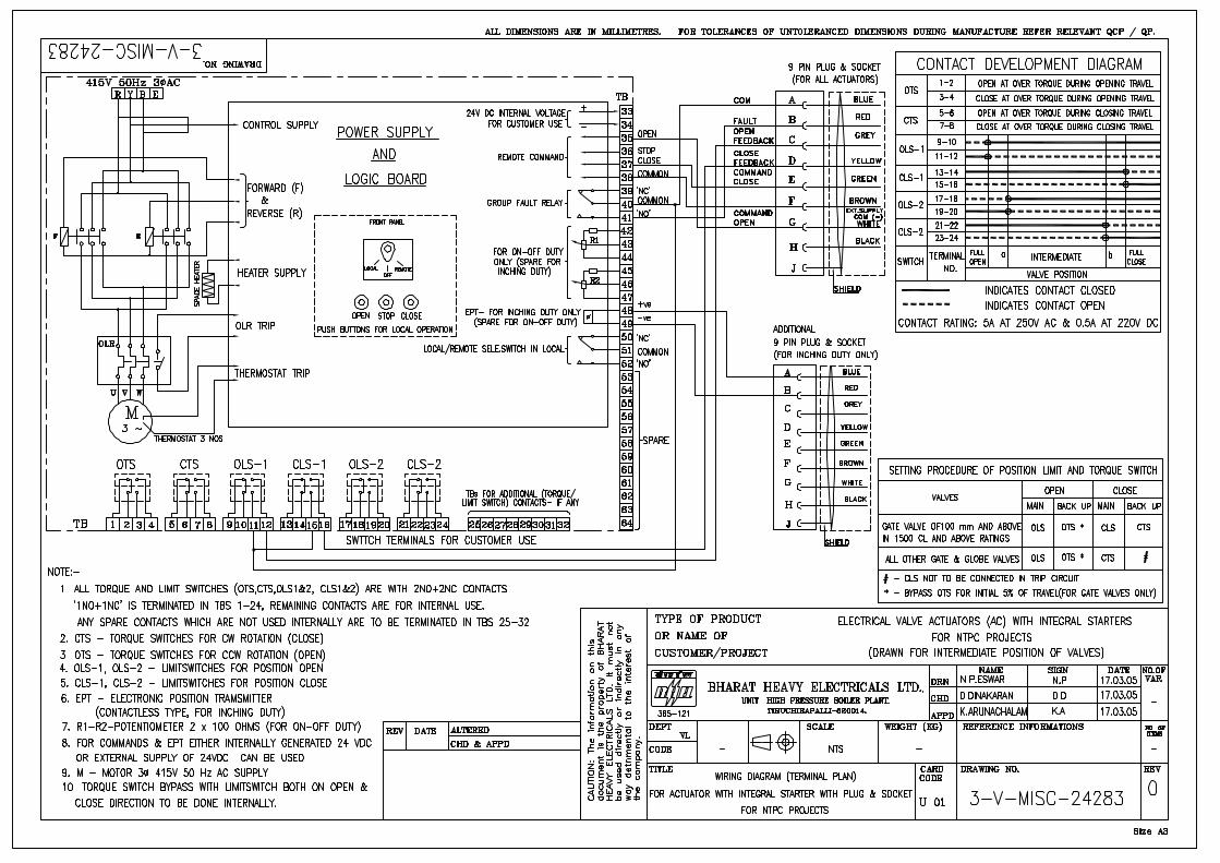
ENCLOSED (BIDDER TO CONFIRM) A: DRG. NO. 3-V-MISC-24227 R00 B: DRG. NO. 3-V-MISC-24550 R00 C: DRG. NO. 3-V-MISC-24283 R00 D: DRG. NO. 4-V-MISC-90271 R11
COLOUR SHADE BLUE (RAL 5012) ENAMEL …….
SHAFT RPM BIDDER TO SPECIFY
OLR SET VALUE BIDDER TO SPECIFY
STARTING / FULL LOAD CURRENT BIDDER TO SPECIFY
NO. OF REV FOR FULL TRAVEL BIDDER TO SPECIFY
@ PWR SUPP TO MTR / STARTER Type 415V, 3PH, AC
@ CONTROL VOLTAGE REQUIREMENT TO BE DERIVED FROM THE POWER SUPPLY TO THE STARTER 24 VDC 110 V
@ ENCLOSURE CLASS OF MOTOR IP 65 IP 67 FLAME PROOF IP 55, TOTALLY ENCL, SELF VENTILATED.
@ INSULATION CLASS CLASS-B CLASS-F
@ WINDING TEMP PROTECTION THERMOSTAT (3 Nos.,1 IN EACH PHASE) ---------------------------------------------------------

SPECIFICATION FOR
MOTORISED VALVE ACTUATOR
SPECIFICATION NO.: PE-SS-387-145-I007
VOLUME
SECTION
REV. NO. 00 DATE: 17.07.2012
SHEET 2 OF 3
Data Sheet A & B
DATA SHEET-A (TO BE FILLED BY PURCHASER)
DATA SHEET-B
(TO BE FILLED-UP BY BIDDER)
FO
RM
NO
. P
EM
-666
6-0
SINGLE PHASE / WRONG PHASE SEQUENCE PROTECTION
REQUIRED
INTEGRAL STARTER
INTEGRAL STARTER REQUIRED NOT REQUIRED
TYPE OF SWITCHING DEVICE CONTACTORS THYRISTORS
TYPE CONVENTIONAL SMART (NON-INTRUSIVE)
STEP DOWN CONT. TRANSFORMER REQUIRED
OPEN / CLOSE PB REQUIRED NOT REQUIRED
STOP PB REQUIRED NOT REQUIRED
INDICATING LAMPS REQUIRED NOT REQUIRED
LOCAL REMOTE S/S REQUIRED NOT REQUIRED
STATUS CONTACTS FOR MONITORING REQUIRED NOT REQUIRED
INTEGRAL STARTER DISTURBED SIGNAL
REQUIRED (O/L RELAY OPERATED, CONT./POWER SUPPLY FAILED, S/S IN LOCAL, TORQUE SWITCH OPTD. MID WAY)
INTERPOSING RELAY (Applicable for integral Starter)
INTERPOSING RELAYS REQUIRED
INTERPOSING RELAY (QUANTITY) 2 NOs. 3 NOs.
DRIVING VOLTAGE 20.5 – 24V DC _____________V DC
DRIVING CURRENT 125mA MAX _____________mA MAX
LOAD RESISTANCE > 192 ohms - <25 k ohms > _______ohms - < __________ohms
TORQUE SWITCH
MFR & MODEL NO. BIDDER TO SPECIFY
OPEN / CLOSE 1 No. 2Nos. / 1 No. 2Nos
CONTACT TYPE 2 NO + 2 NC
RATING 5A 240V AC AND 0.5A 220V DC
CALIBRATED KNOBS(OPEN&CLOSE TS) REQUIRED FOR SETTING DESIRED TORQUE
ACCURACY +3% OF SET VALUE
LIMIT SWITCH
MFR & MODEL NO. BIDDER TO SPECIFY
OPEN : INT : CLOSE 1 No 2 Nos.
2 Nos. (ADJ.) 1 No. 2Nos.
CONTACT TYPE 2 NO + 2 NC
RATING (AC / DC) 5A 240V AC AND 0.5A 220V DC

SPECIFICATION FOR
MOTORISED VALVE ACTUATOR
SPECIFICATION NO.: PE-SS-387-145-I007
VOLUME
SECTION
REV. NO. 00 DATE: 17.07.2012
SHEET 3 OF 3
Data Sheet A & B
DATA SHEET-A (TO BE FILLED BY PURCHASER)
DATA SHEET-B
(TO BE FILLED-UP BY BIDDER)
FO
RM
NO
. P
EM
-666
6-0
POSITION TRANSMITTER
POSITION TRANSMITTER (For inching duty)
REQUIRED NOT REQUIRED
MFR & MODEL NO. BIDDER TO SPECIFY
TYPE ELECTRONIC (2 WIRE) R/I CONVERTER ELECTRONIC (2 WIRE) CONTACTLESS
SUPPLY 24V DC ………
OUTPUT 4-20mA
ACCURACY + 1% FS
SPACE HEATER
@SPACE HEATER REQUIRED
@ POWER SUPPLY
@ RATING 415v, 3PH, AC FOR RATING > 0.2KW; SINGLE PHASE FOR RATING < 0.2KW
TERMINAL BOX
MOTOR TERMINAL BOX REQUIRED
ACTUATOR TERMINAL BOX REQUIRED
ENCL CLASS MTR T.B. / ACTUATOR T.B. @ IP 65 @……… IP65 ……….
@ EARTHING TERMINAL REQUIRED
PLUG & SOCKET(9 PIN) (FOR COMMD, LS/TS FEED BACK, PoT)
REQUIRED NOT REQUIRED 2 NOS. ----------------
CABLE GLANDS
@ POWER CABLE GLAND SIZE:--DURING DETAIL ENGINERING
@ SPACE HEATER CABLE GLAND SIZE: 2C x 2.5 sq. mm
OTHER CONTROL CABLE GLANDS-1 APPLICABLE
OTHER CONTROL CABLE GLANDS-2 APPLICABLE
WEIGHT TOTAL WEIGHT (ACTUATOR + ACCESSORIES)
BIDDER TO SPECIFY _________________ Kg.
NOTES:
1. SCOPE: DESIGN, MANUFACTURE, INSPECTION, TESTING AND DELIVERY TO SITE OF ELECTRIC ACTUATOR FOR INCHING OR OPEN / CLOSE DUTY. 2. CODES & STANDARDS: DESIGN AND MATERIALS USED SHALL COMPLY WITH THE RELEVANT LATEST NATIONAL AND INTERNATION STANDARD. AS A MINIMUM,
THE FOLLOWING STANDARDS SHALL BE COMPLIED WITH: IS-9334, IS-2147, IS-2148, IS-325, IS-2959, IS-4691 AND IS-4722
3. TEMPERATURE RISE SHALL BE RESTRICTED TO 70 DEG. C FOR AMBIENT TEMPERATURE OF 50 DEG C. 4. CABLE GLANDS OF DOUBLE COMPRESSION TYPE, BRASS MATERIAL SHALL BE PROVIDED. 5. THE TORQUE SWITCHES SHALL BE PROVIDED WITH MECHANICAL LATCHING DEVICE TO PREVENT OPERATION WHEN UNSEATING FROM THE END POSITIONS.
THE LATCHING DEVICE SHALL UNLATCH AS SOON AS THE VALVE LEAVES THE END POSITION. IF SUCH PROVISION IS NOT POSSIBLE, THE TORQUE SWITCHES SHALL BE BYPASSED BY END-POSITION LIMIT SWITCHES WHICH OPENS ON VALVE LEAVING END POSITION.THESE LIMIT SWITCHES ARE ADDITIONAL TO THE NUMBER OF LIMIT SWITCHES SPECIFIED ELSEWHERE.
6. THE MOTOR SHALL OPERATE SATISFACTORILY UNDER THE +/- 10% SUPPLY VOLTAGE VARIATION AT RATED FREQUENCY, -5% TO +3% VARIATION IN
FREQUENCY AT RATED SUPPLY VOLTAGE, SIMULTANEOUS VARIATION IN VOLTAGE & FREQUENCY THE SUM OF ABSOLUTE PERCENTAGE NOT EXCEEDING 10%. 7. THE MOTOR SHALL BE SUITABLE FOR DIRECT ON LINE STARTING. .
NOTES* = TO BE FILLED BY MPL (LEAD AGENCY). @= TO BE FILLED BY ES

MOUDA STPP-II (2x660MW) / SOLAPUR STPP (2 x 660MW) / NABINAGAR STPP (3x 660MW) /MEJA TPP-I (2 x 660MW) /
RAGHUNATHPUR TPP PHASE-II (2 x660MW) STEAM GENERATOR PACKAGE
TECHNICAL SPECIFICATION SECTION-VI
BID DOC NO.: CS-9575/ 9571/ 0370/ 0360/ 9586-102-2
SUB-SECTION-IV: I6
PROCESS CONNECTION AND PIPING

CLAUSE NO. TECHNICAL REQUIREMENTS
MOUDA STPP-II (2x660MW) / SOLAPUR STPP (2 x 660MW) / NABINAGAR STPP (3x 660MW) /
MEJA TPP-I (2 x 660MW) / RAGHUNATHPUR TPP PHASE-II (2 x660MW)
STEAM GENERATOR PACKAGE
TECHNICAL SPECIFICATION SECTION-VI
BID DOC NO.: CS-9575/ 9571/ 0370/ 0360/ 9586-102-2
PART - B SUB-SECTION-IV
I-6 (PROCESS CONNECTION & PIPING)
PAGE 1 OF 6
PROCESS CONNECTION AND PIPING
1.00.00 PROCESS CONNECTION PIPING
1.01.00 The Contractor shall provide, install and test all required material for completeness of Impulse Piping System and Air Piping System as per the requirements of this Sub-section enclosed installation drawings and source connection drawings on as required basis for the connection of instruments and control equipment to the process and make the system complete. The installation & source connection of various items shall generally as per installation drawings (drawing no. 0000-999-POI-A-022 to 034) and source correction drawings (drawing nos. 0000-999-POI-A-035), however, the Contractor shall furnish during detailed engineering all relevant drawings, material and tech. specifications of various items service wise for Employer's approval.
1.01.01 All materials supplied under this Sub-section shall be suitable for intended service, process, operating conditions and type of instruments used and shall fully conform to the requirements of this specification. The material offered by the Bidder shall be from reputed, experienced manufacturer whose guaranteed and trouble free operation has been proven at least for two years in not less than two pulverized coal fired utility stations.
1.02.00 IMPULSE PIPING, TUBING, FITTINGS, VALVES AND VALVE MANIFOLDS
1.02.01 All impulse pipe shall be of seamless type conforming to ANSI B36.10 for schedule numbers, sizes and dimensions etc. The material of the impulse pipe shall be same as that of main process pipe. For various applications specification of impulse pipe materials and associated fittings and valves shall be as given in Table PCP. For protection against sea environment all impulse pipes fittings etc. shall be provided with durable epoxy coating with poly urethane finish.
1.02.02 Stainless steel tube shall be provided inside enclosures & racks from tee connection to valve manifold and then to instrument. For high pressure/temperature applications (piping class A, B, C &D of the table no. PCP) the material shall be ASTM A 213 TP 316H and for other applications material shall be ASTM A 213 TP 316L. The wall thickness of the tube shall be in accordance with the ANSI B31.1 standard.
1.02.03 All fittings shall be forged steel and shall conform to ANSI B16.11. The material of forged tube fittings for shaped application (e.g. Tee, elbow etc.) shall be ASTMA 182 Gr. 316 H for high pressure/ temperature applications (as defined above) and ASTMA 182 Gr. 316L for other applications. The material for bar stock tube fitting (for straight application) shall be 316 SS. Metal thickness in the fittings shall be adequate to provide actual bursting strength equal to or greater than those of the impulse pipe or SS tube, with which they are to be used.
1.02.04 The source shut-off (primary process root valve) and blow down valve shall be of 1/2 inch size globe valve type for all applications except for air and flue gas service wherein no source shut-off valves are to be provided. The disc and seat ring materials of carbon steel and alloy steel valves be ASTM A-105 and ASTM A-182, Gr. F22, hard faced with stellite (minimum hardness - 350 BHN.) The surface finish of 16 RMS or greater is required in the area of stem packing. The valve design shall be such that the seats can be reconditioned and stem and disc may be replaced without removing the valve body from the line.
1.02.05 The valve manifolds shall be of 316 stainless steel with pressure rating suitable for intended application. 2 valve manifold and 3 valve manifold shall be used for pressure measurements using pressure transmitters/ pressure switches and diff. pressure transmitter/ switches respectively. 5-valve manifold shall be used for remaining applications like DP, flow and level measurements.
CLAUSE NO. TECHNICAL REQUIREMENTS
MOUDA STPP-II (2x660MW) / SOLAPUR STPP (2 x 660MW) / NABINAGAR STPP (3x 660MW) /
MEJA TPP-I (2 x 660MW) / RAGHUNATHPUR TPP PHASE-II (2 x660MW)
STEAM GENERATOR PACKAGE
TECHNICAL SPECIFICATION SECTION-VI
BID DOC NO.: CS-9575/ 9571/ 0370/ 0360/ 9586-102-2
PART - B SUB-SECTION-IV
I-6 (PROCESS CONNECTION & PIPING)
PAGE 2 OF 6
1.02.06 For Pr./D.P gauges in fluid application two-way globe valve on each impulse line to the instrument and in A/F application two-way gate valve on each impulse line to the instrument shall be provided near the instrument. These shall be in addition to the three ways gauge cock provided along with the pressure /D.P gauges.
2.00.00 AIR SUPPLY PIPING
2.01.00 All pneumatic piping, fittings, valves, air filter cum regulator and other accessories required for instrument air for the various pneumatic devices/ instruments shall be provided.
2.01.01 This will include as a minimum air supply to pneumatically operated control valves, actuators, instruments, continuous and intermittent purging requirements of etc.
2.02.00 For individual supply line and control signal line to control valve, 1/4-inch size light drawn tempered copper tubing conforming to ASTM B75 shall be used. The thickness of cu-tubing shall not be less than 0.065 inch and shall be PVC coated. The fittings to be used with copper tubes shall be of cast brass, screwed type.
2.03.00 All other air supply lines of 1/2 inch to 2 inch shall be of mild steel hot dipped galvanized inside and outside as per IS-1239, heavy duty with threaded ends. The threads shall be as per ASA B.2.1. Fittings material shall be of forged carbon steel A234 Gr. WPB galvanized inside and outside, screwed as per ASA B2.1. Dimensions of fittings shall be as per ASA B16.11 of rating 3000 lbs.
2.04.00 For air supply to various devices mentioned above, the bidder shall provide 2 inch size GI pipe header with isolation valve from the instrument air and service air terminal points. In the boiler area the 2 inch head shall be provided upto top most elevation of boiler floor and from this 2 inch header, 1 inch sub-header shall be branched off at each floor with isolation valve. From this 1 inch sub-header, branch line of 1/2 inch, with isolation valve shall be provided upto various devices. Similar system is to be followed for service air required for intermittent purging in the Local Instrument Enclosures (LIEs) etc.
2.05.00 All instrument air filters cum regulator set with mounting accessories shall be provided for each pneumatic device requiring air supply. The filter regulators shall be suitable for 10-kg/ sq.cm max. Inlet pressure. The filter shall be of size 5 microns and of material sintered bronze. The air set shall have 2-inch size pressure gauge and built in filter housing blowdown valve. The end connection shall be as per the requirement to be finalized during detailed engineering.
2.06.00 All the isolation valves in the air supply line shall be gate valves as per ASTM B62 inside screw rising stem, screwed female ends as per ASA B2.1. Valve bonnet shall be union type & trim material shall be stainless steel, body rating 150 pounds ASA. The valve sizes shall be ½ inch to 2 inch.
2.07.00 Purge Air Connection for Air and Flue gas Applications
The continuous purging with instrument air shall be done, for all air and flue gas measurements excepting instrument air and service air instruments, at the process source connection end. Necessary arrangements required for continuous purging shall be provided inside all the Air and Flue gas enclosures as per enclosed drawing no. 0000-999-POI-A-034.
For intermittent purging with service air, necessary arrangements inside all the air and Flue gas enclosures shall be provided. The SS three way valve provided in the SS tubing shall be used for isolating the transmitter & connecting the service air quick disconnect line.

CLAUSE NO. TECHNICAL REQUIREMENTS
MOUDA STPP-II (2x660MW) / SOLAPUR STPP (2 x 660MW) / NABINAGAR STPP (3x 660MW) /
MEJA TPP-I (2 x 660MW) / RAGHUNATHPUR TPP PHASE-II (2 x660MW)
STEAM GENERATOR PACKAGE
TECHNICAL SPECIFICATION SECTION-VI
BID DOC NO.: CS-9575/ 9571/ 0370/ 0360/ 9586-102-2
PART - B SUB-SECTION-IV
I-6 (PROCESS CONNECTION & PIPING)
PAGE 3 OF 6
Purging arrangement is not required for Instrument air and service air measurement applications.
3.00.00 INSTALLATION AND ROUTING
3.01.00 Instrument Piping System
3.01.01 For steam and liquid measurements, the impulse pipe should preferably slope downward from source connection to instrument and instrument shall be installed below the source point. If due to any reason instrument is installed above the source point, the impulse pipe should slope upwards continuously and a 'pigtail' should be provided at the instrument to assure water seal for temperature protection. For vacuum measurements instrument shall be installed above source point and impulse pipe should slope upwards.
3.01.02 Impulse piping for air and flue gas shall slope upwards and instrument shall be installed above source point. If this requirement cannot be met special venting or drain provision shall be provided with vent & drain lines along with isolation valves and other accessories including drainpipes. This drain is to be connected to plant drain through open funnel also.
3.01.03 All impulse piping shall be installed to permit free movement due to thermal expansion. Wherever required expansion loops shall be provided.
3.01.04 Special accessories such as condensing pots/ reservoirs shall be provided and installed wherever required. In any case condensing pots shall be provided for all level measurements in steam and water services, all flow measurement in steam services and flow measurements water services above 120 Deg.C. For drum/ separator level measurement required balancing chamber shall be provided.
3.01.05 Color coding of all impulse pipes shall be done by the bidder in line with the colour coding being followed for the parent pipes.
3.02.00 Instrument Air & Service Air Piping/ Tubing System
3.02.01 Instrument air & service air headers and their branches with all associated fittings & accessories shall be provided for giving supply to all consumers, as per the requirements. Air piping shall be installed always with a slope of over 1/20 to prevent accumulation of water within the pipe.
3.02.02 Single and multi tubes shall run with the minimum number of changes in direction. Suitable identification tags shall be provided for easy checkup and for connections.
4.00.00 PIPING/TUBING SUPPORT
4.01.00 Impulse piping and sample piping shall be supported at an interval not exceeding 1.5 meters. Each pipe shall be supported individually using slotted angle mounted clamps with necessary fixtures. Tubing shall run in proper perforated trays with proper cover. Tubing shall be supported inside the trays by aluminium supports. Hangers and other fixtures required for support of piping and trays shall be provided, either by welding or by bolting on walls, ceilings and structures. Hanger clamps and other fastening hardware shall be of corrosion resistant metals and hot-dip galvanized.
CLAUSE NO. TECHNICAL REQUIREMENTS
MOUDA STPP-II (2x660MW) / SOLAPUR STPP (2 x 660MW) / NABINAGAR STPP (3x 660MW) /
MEJA TPP-I (2 x 660MW) / RAGHUNATHPUR TPP PHASE-II (2 x660MW)
STEAM GENERATOR PACKAGE
TECHNICAL SPECIFICATION SECTION-VI
BID DOC NO.: CS-9575/ 9571/ 0370/ 0360/ 9586-102-2
PART - B SUB-SECTION-IV
I-6 (PROCESS CONNECTION & PIPING)
PAGE 4 OF 6
5.00.00 SHOP AND SITE TESTS
5.01.00 General Requirements
5.01.01 The equipment and work performed as per this Sub-section shall be subject to shop and site test as per requirements of Sub-section-Q (Quality Assurance & Inspection) other applicable clauses of this Sub-section and Employer approved quality assurance plan.
5.01.02 Hydrostatic and pneumatic tests shall be performed on all pipes, tubing and systems and shall conform to ANSI B31.1.
5.02.00 Hydrostatic Testing
5.02.01 All instrument piping/ tubing shall be hydrostatically tested upon completion of erection. The test pressure shall be 1.5 times the maximum process pressure. The test shall be performed either with the testing of associated process piping or without the associated process piping (by closing the root valve). In both the cases the instrument shall be isolated by closing the shut-off valve.
5.03.00 Air Testing
5.03.01 All air headers & branch pipes shall be air tested by pressure decay method as per ANSI B31.1. Flexible hoses and short signal tubing shall be tested at normal pressure for leakage. Long signal tubing shall be tested by charging each tube with air at 2 kg/ sq. cm. through a bubbler sight glass. The boiler draft and vacuum piping shall be air tested by the same method as long signal tubing.
6.00.00 LOCAL INSTRUMENT ENCLOSURE AND RACKS
Transmitters, switches, devices ,temperature transmitters etc. (except for all fuel oil applications which shall be mounted close to be tapping points) mounted in the field shall be suitably grouped together and mounted (i) local instruments enclosure in case of open areas of the plant like boiler area, etc. and (ii) In local instrument racks in case of covered areas. Gauges are to be mounted on a channel or a frame or a rack (Gauges shall not be mounted directly on process pipe). These local instrument enclosures and racks shall be furnished as per the actual requirements finalized during detailed engineering stage. The exact grouping of instruments in a particular instrument enclosure/instrument rack shall be as finalized during detailed engineering stage subject to Employer's approval.
For mounting of PT/DPT/LT/FT, LIEs / LIRs shall be of three types depending on the number of transmitters located in it as elaborated in the typical GA of the LIE/LIR, drawing no. 0000-999-POI-A-064 (Sh Nos. 1 to 3 of 5).
For mounting of Temperature Transmitters, LIEs / LIRs shall be as elaborated in the, drawing no. 0000-999-POI-A-064 (Sh No. 4 and 5 of 4).
These dimensions and number of instruments indicated therein are only indicative and the exact dimensions along with the number of instruments shall be as finalized during detailed engineering stage without any price repercussions.
The internal layout shall be such that the impulse piping/ blow down lines are accessible from back side of the enclosure / rack and the transmitters etc. are accessible from front side for easy maintenance. Bulkheads, especially designed to provide isolation from process line vibration shall be installed on instrument enclosures/racks to meet the process sensing line connection requirement.

CLAUSE NO. TECHNICAL REQUIREMENTS
MOUDA STPP-II (2x660MW) / SOLAPUR STPP (2 x 660MW) / NABINAGAR STPP (3x 660MW) /
MEJA TPP-I (2 x 660MW) / RAGHUNATHPUR TPP PHASE-II (2 x660MW)
STEAM GENERATOR PACKAGE
TECHNICAL SPECIFICATION SECTION-VI
BID DOC NO.: CS-9575/ 9571/ 0370/ 0360/ 9586-102-2
PART - B SUB-SECTION-IV
I-6 (PROCESS CONNECTION & PIPING)
PAGE 5 OF 6
Vibration dampeners shall be installed for each enclosure / rack.
The enclosures shall be constructed of 3 mm sheet plate and shall be of modular construction with one or more modules and two end assemblies bolted together to form an enclosure. Double inter locking doors shall be provided. The doors shall be the three-point locking type constructed of not less than 1.6 mm thick steel. Doors shall have concealed quick removal type pinned hinges and locking handles. Door locks shall accept the same key.
Gaskets shall be used between all mating sections to achieve protection class of IP-55.
The instrument racks shall be free standing type constructed of suitable 5 mm thick channel frame of steel and shall be provided with a canopy to protect the equipment mounted in racks from falling objects, water etc. The canopy shall not be less than 3 mm thick steel, and extended beyond the ends of the rack. Bulk heads, especially designed to provide isolation from process line vibration shall be provided. Exact fabrication details shall be as finalized during detailed engineering stage. The junction box for racks also shall conform to IP 55 protection class.
Enclosures/racks shall be reinforced as required to ensure true surface and to provide adequate support for instruments and equipment mounted therein. Centre posts or any member which would reduce access shall not be provided.
Each transmitter enclosure housing instruments requiring purge air for continuous air purging, shall be provided with common purge air header, redundant air filter regulators of sufficient capacity, required pressure gauges, valves, fittings, SS tubing and individual purge meters for each purge line etc. as required and indicated in Instrument Installation drawings enclosed herewith.
A 15 mm NB service air header shall be furnished in each instrument enclosure housing air & flue gas and coal mill instruments. The header shall be furnished complete with a pressure regulating valve, pressure gauge, and quick disconnect connections. A hose for connecting each header to the draft instrument line four-way valves shall be furnished. The hose shall be self-storing nylon tubing having a burst pressure of 15 kg/sq. cm. The size of the hose shall be 1/2" minimum. The service air header shall originate at a bulkhead penetration or fitting located on one of the bulkhead plates.
The contractor shall prepare the piping drawings and the general arrangement layout drawings for each of the enclosures and racks. Special attention shall be given in the piping layout to avoid air traps in liquid filled piping or water pockets in piping intended to be dry. Drawings shall indicate the arrangement of all equipment, piping, valves and fittings within, the enclosure/racks and shall be subject to Employer's approval.
All liquid filled blow down lines, except those measuring vacuum shall be connected to a two inch header which is extended through one end of the enclosure and turned downward for directing the blow down into a drain. The material of the blow down header shall be carbon steel as per ASTM A 106 Gr. C.
The Contractor shall submit to the Employer with his proposal a copy of his welding procedure specification together with proof of his compliance with the latest applicable welding ANSI code. Prior to any welding being performed, the Contractor shall submit the qualifications of the craftsmen who will perform the work.

MO
UD
A S
TPP-
II (2
x660
MW
) / S
OLA
PUR
STP
P (2
x 6
60M
W) /
N
AB
INA
GAR
STP
P (3
x 66
0MW
) / M
EJA
TPP
-I (2
x 6
60M
W) /
R
AG
HU
NA
THPU
R T
PP P
HAS
E-II
(2 x
660M
W)
STEA
M G
ENER
ATO
R P
AC
KA
GE
TEC
HN
ICAL
SPE
CIF
ICAT
ION
SE
CTI
ON
-VI
BID
DO
C N
O.:
CS-
9575
/ 957
1/ 0
370/
03
60/ 9
586-
102-
2
PAR
T - B
SU
B-S
ECTI
ON
-IV
I-6 (
PRO
CES
S C
ON
NEC
TIO
N &
PI
PIN
G)
PAG
E 6
OF
6
7.00
.00
TAB
LE P
CP
Sys
tem
/Lin
e D
escr
iptio
n P
ipin
g C
lass
Im
puls
e P
ipe
Mat
eria
l S
ched
ule
(Siz
e)
Mat
eria
ls
for
Fitti
ng/V
alve
Bod
y Va
lve
Stem
M
ater
ial
Rat
ing
of
Pip
ing/
Fitt
ings
P
r. C
lass
of
Val
ve
Mai
n S
team
/ U
pstre
am
of
HP
by
pass
an
d A
uxili
ary
Ste
am
Pre
ssur
e re
duci
ng
valv
e,
Dru
m L
evel
A
AS
TM-A
335
Gr.P
-91/
22
(Not
e-2)
XXS
(1/2
in
ch)
(Not
e-3)
(N
ote-
3)
9000
lb
3000
SP
L
BFP
dis
ch, s
uper
heat
er a
ttem
pera
tor,
spra
y to
P
RD
S,
Pho
spha
te
dozi
ng
pp
disc
h,
BC
W
pum
p
B
AS
TM-A
106
Gr.
C16
0 (1
/2 in
ch)
AS
TM-A
105
AS
TM-A
-182
G
r.F6a
60
00 lb
25
00
Reh
eate
r atte
mpe
rato
r C
A
STM
-A10
6 G
r. C
160
(1/2
inch
) A
STM
-A10
5 -d
o-
6000
lb
1500
Hot
R
ehea
t/ do
wn
stre
am
of
Aux
. S
team
pr
ess.
Red
ucin
g va
lve
upto
des
uper
hea
ter/
Flas
h ta
nk d
rain
man
ifold
, HP
hea
ter l
evel
.
D
AS
TM-A
335
Gr.
P-9
1/22
(Not
e-2)
16
0 (1
/2 in
ch)
AS
TM-A
182
Gr.F
-22
(N
ote-
3)
3000
lb
900
Col
d re
heat
upt
o Te
e-of
f fo
r H
P B
ypas
s /
Ext
ract
ion
stea
m to
HP
H
E
AS
TM-A
335
Gr.P
-22
80 (1
/2 in
ch)
AS
TM-A
182
Gr.F
-22
A
STM
-A-1
82
Gr.F
6a
3000
lb
800
Col
d re
heat
do
wn
stea
m
of
Tee-
off
(HP
B
ypas
s)
F A
STM
-A10
6 G
r. C
80 (1
/2 in
ch)
AS
TM-A
105
-do-
30
00 lb
80
0
BFP
suc
tion,
Con
dens
ate
Sys
tem
/ E
xtra
ctio
n to
LP
H/
Ext
-4 t
o B
FPT,
Dea
erat
or/
auxi
liary
st
eam
, se
rvic
e ai
r, in
st a
ir, E
CW
pum
p, A
CW
pu
mp
and
othe
r low
pr w
ater
ser
vice
s
G
AS
TM-A
106
Gr.
B80
(1/2
inch
) A
STM
-A10
5 -d
o-
3000
lb
800
Air/
Flu
e ga
s ou
tsid
e fu
rnac
e
M
AS
TM-A
106
Gr.
B/C
80
(3/4
inch
) A
STM
-A10
5 -d
o-
3000
lb
800
Air/
Flu
e ga
s in
side
furn
ace
N
AS
TM-A
335
Gr.P
22
80 (3
/4 in
ch)
AS
TM-A
182
Gr.
F-22
-d
o-
3000
lb
800
NO
TE:
1 R
atin
g of
pip
ing/
fittin
gs/v
alve
s et
c. is
sub
ject
ed to
the
final
des
ign
pres
sure
& te
mpe
ratu
re d
urin
g th
e de
taile
d en
gine
erin
g.
2 In
cas
e te
mpe
ratu
re is
mor
e th
an 5
40 d
eg C
, the
mat
eria
l sha
ll be
P-9
1 on
ly.
3 M
ater
ial s
hall
be c
ompa
tible
with
that
of t
he im
puls
e pi
pe m
ater
ial a
nd d
esig
n pa
ram
eter
.
4 S
epar
ator
rela
ted
impu
lse
pipi
ng m
ater
ial s
hall
be a
s pe
r mai
n pr
oces
s pi
pe/ta
nk m
ater
ial
MOUDA STPP-II (2x660MW) / SOLAPUR STPP (2 x 660MW) / NABINAGAR STPP (3x 660MW) /MEJA TPP-I (2 x 660MW) /
RAGHUNATHPUR TPP PHASE-II (2 x660MW) STEAM GENERATOR PACKAGE
TECHNICAL SPECIFICATION SECTION-VI
BID DOC NO.: CS-9575/ 9571/ 0370/ 0360/ 9586-102-2
SUB-SECTION-IV: I7
INSTRUMENTATION AND POWER SUPPLY CABLE

CLAUSE NO. TECHNICAL REQUIREMENTS
MOUDA STPP-II (2x660MW) / SOLAPUR STPP (2 x 660MW) / NABINAGAR STPP (3x 660MW) /
MEJA TPP-I (2 x 660MW) / RAGHUNATHPUR TPP PHASE-II (2 x660MW)
STEAM GENERATOR PACKAGE
TECHNICAL SPECIFICATION SECTION-VI
BID DOC NO.: CS-9575/ 9571/ 0370/ 0360/ 9586-102-2
PART - B SUB-SECTION-IV: I7(INSTR. AND POWER
SUPPLY CABLE)
PAGE 1 OF 14
INSTRUMENTATION AND POWER SUPPLY CABLE
1.00.00 INSTRUMENTATION CABLE, POWER SUPPLY CABLE, INTERNAL WIRING AND ELECTRICAL FIELD CONSTRUCTION MATERIAL
1.01.00 General Requirements
1.01.01 All cables including special cables, internal wiring and electrical field construction material shall conform to this specification, Employer approved detail engineering drawings & documents and the latest edition of the relevant standards & guidelines. The Bidder shall furnish all material and services required for the completeness of the work identified in his scope as per this specification.
1.01.01 The Contractor shall supply, erect, terminate and test all instrumentation cables for control and instrumentation equipment/devices/systems included under Contractor's scope as illustrated in the enclosed Drg. No. 0000-101/102-POI-A-021 and ensuring completeness of the control system.
1.01.02 Any other application where it is felt that instrumentation cables are required due to system/operating condition requirements, are also to be provided by Contractor.
1.01.03 Other type of cables like fiber optic/co-axial cables for system bus, cables for connection of peripherals etc. (under Contractor's scope) are also to be furnished by the Contractor.
1.01.04 Contractor shall supply all cable erection and laying hardware from the main trunk routes like branch cable trays/sub-trays, supports, flexible conduits, cable glands, lugs, pull boxes etc. on as required basis for all the systems covered under this specification.
1.01.05 Wherever the quantity has been defined as on as required basis, the same are to be furnished by contractor on as required basis within his quoted lump sump price without any further cost implication to the Employer.
2.00.00 Specification of Instrumentation cable
2.01.00 Common Requirements
-------------------------------------------------------------------------------------------------------------------------- S. No. Property Requirement --------------------------------------------------------------------------------------------------------------------------- 1 Voltage grade 225 V (peak value)
2. Codes and standard All instrumentation cables shall comply with VDE 0815, VDE 0207, Part 4, Part 5, Part 6, VDE 0816, VDE 0472, SEN 4241475, ANSI MC 96.1, IS-8784, IS-10810 (latest editions) and their amendments read along with this specification.
3. Continuous operation suitability At 70 deg. C for all types of cables, while 205 Deg C for Type-C cables.
4. Progressive automatic on-line To be provided at every one meter on sequential marking of length outer sheath. in meters
CLAUSE NO. TECHNICAL REQUIREMENTS
MOUDA STPP-II (2x660MW) / SOLAPUR STPP (2 x 660MW) / NABINAGAR STPP (3x 660MW) /
MEJA TPP-I (2 x 660MW) / RAGHUNATHPUR TPP PHASE-II (2 x660MW)
STEAM GENERATOR PACKAGE
TECHNICAL SPECIFICATION SECTION-VI
BID DOC NO.: CS-9575/ 9571/ 0370/ 0360/ 9586-102-2
PART - B SUB-SECTION-IV: I7(INSTR. AND POWER
SUPPLY CABLE)
PAGE 2 OF 14
5. Marking to read 'FRLS' To be provided at every 5 meters on outer sheath except for Type-C cable.
6. Allowable Tolerance on +/- 2 mm (maximum) over the overall diameter declared value in data sheet
7. Variation in diameter Not more than 1.0 mm throughout the length of cable.
8 Ovality at any cross-section Not more than 1.0 mm
9 Others a) Durable marking at intervals not exceeding 625 mm shall include manufacturer's name, insulation material, conductor's size, number of pairs, voltage rating, type of cable, year of manufacturer to be provided.
b) Cables shall be suitable for laying in conduits, ducts, trenches, racks and underground-buried installation
c) Repaired cables shall not be acceptable. ---------------------------------------------------------------------------------------------------------------------------
2.02.00 Specific Requirements
--------------------------------------------------------------------------------------------------------------------------- Specification Type-A Type-B Type F & G Type-C cable Requirements cable cable cable ---------------------------------------------------------------------------------------------------------------------------
A. Conductors
Cross section area (Same as T/C ) 0.5 sq. mm 0.5 sq. mm.
Conductor material ANSI type ANSI type High ANSI type KX KX SX conductivity Annealed bare copper
Colour code Yellow-Red Black-Red As per VDE-815 Yellow-Red
Conductor Grade As per ANSI MC 96.1 Electrolytic As per ANSI MC 96.1 No & dia of 7x0.3 mm (nom) strands
No. of Pairs 2 2 2,4,8,12,16,24,48 2
Max. conductor As per ANSI MC 96.1 73.4 (loop) As per ANSI resistance per Km MC 96.1 (in ohm) at 20 deg. C
CLAUSE NO. TECHNICAL REQUIREMENTS
MOUDA STPP-II (2x660MW) / SOLAPUR STPP (2 x 660MW) / NABINAGAR STPP (3x 660MW) /
MEJA TPP-I (2 x 660MW) / RAGHUNATHPUR TPP PHASE-II (2 x660MW)
STEAM GENERATOR PACKAGE
TECHNICAL SPECIFICATION SECTION-VI
BID DOC NO.: CS-9575/ 9571/ 0370/ 0360/ 9586-102-2
PART - B SUB-SECTION-IV: I7(INSTR. AND POWER
SUPPLY CABLE)
PAGE 3 OF 14
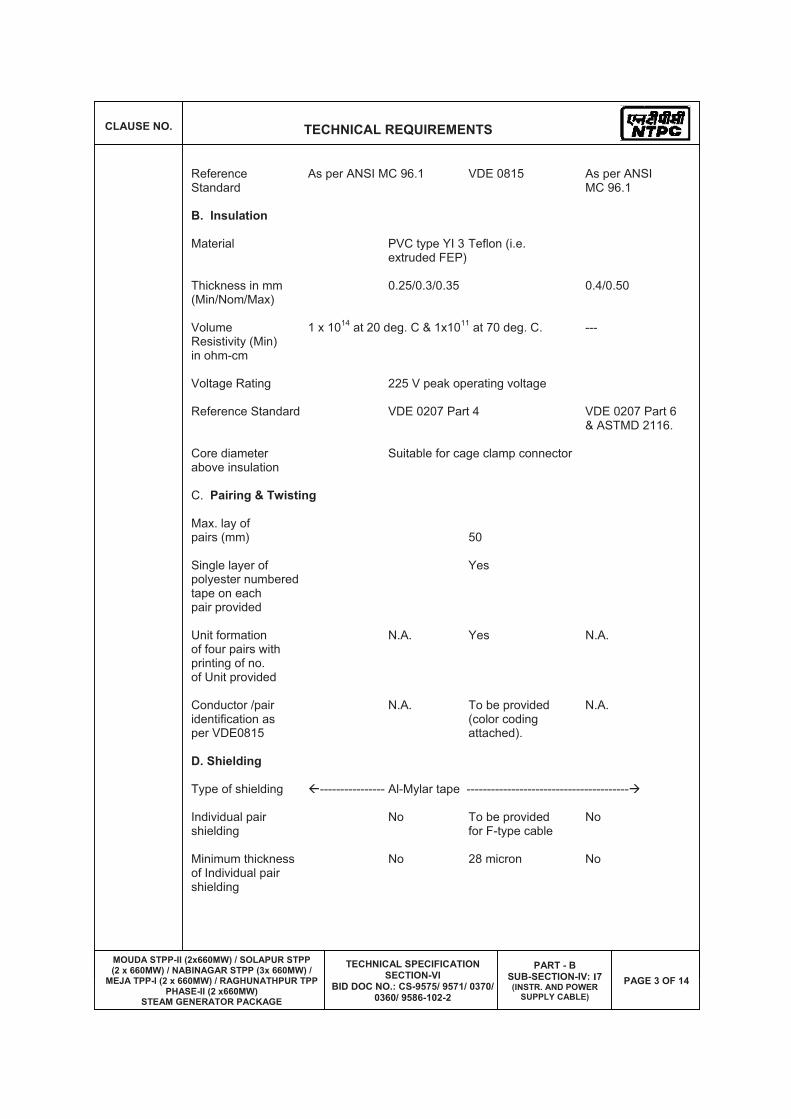
Reference As per ANSI MC 96.1 VDE 0815 As per ANSI Standard MC 96.1
B. Insulation
Material PVC type YI 3 Teflon (i.e. extruded FEP)
Thickness in mm 0.25/0.3/0.35 0.4/0.50 (Min/Nom/Max)
Volume 1 x 10¹⁴ at 20 deg. C & 1x10¹¹ at 70 deg. C. --- Resistivity (Min) in ohm-cm
Voltage Rating 225 V peak operating voltage
Reference Standard VDE 0207 Part 4 VDE 0207 Part 6 & ASTMD 2116.
Core diameter Suitable for cage clamp connector above insulation
C. Pairing & Twisting
Max. lay of pairs (mm) 50
Single layer of Yes polyester numbered tape on each pair provided
Unit formation N.A. Yes N.A. of four pairs with printing of no. of Unit provided
Conductor /pair N.A. To be provided N.A. identification as (color coding per VDE0815 attached).
D. Shielding
Type of shielding �---------------- Al-Mylar tape ----------------------------------------�
Individual pair No To be provided No shielding for F-type cable
Minimum thickness No 28 micron No of Individual pair shielding

CLAUSE NO. TECHNICAL REQUIREMENTS
MOUDA STPP-II (2x660MW) / SOLAPUR STPP (2 x 660MW) / NABINAGAR STPP (3x 660MW) /
MEJA TPP-I (2 x 660MW) / RAGHUNATHPUR TPP PHASE-II (2 x660MW)
STEAM GENERATOR PACKAGE
TECHNICAL SPECIFICATION SECTION-VI
BID DOC NO.: CS-9575/ 9571/ 0370/ 0360/ 9586-102-2
PART - B SUB-SECTION-IV: I7(INSTR. AND POWER
SUPPLY CABLE)
PAGE 4 OF 14
Overall cable To be provided assembly shielding
Minimum thickness 55 micron of Overall cable assembly shielding
Shielding coverage 100% with at least 20% overlap
Drain wire provided N.A. Yes (for F-type) N.A. for individual shield 7-strand 20 AWG (0.51 mm2) annealed Tin coated copper
Drain wire provided Yes. 7-strand 20 AWG (0.51 mm2) annealed Tin coated copper for overall shield
E. FILLERS
Non-hygroscopic, To be provided flame retardant F. Outer Sheath
Material �--- Extruded PVC compound YM1 with---� Teflon (i.e. FRLS properties extruded FRP)
Minimum 1.8 mm 0.4 mm Thickness at any point
Nominal >1.8 mm 0.5 mm Thickness at any point
Color Blue
Resistant to Required water, fungus, termite & rodent attack
Oxygen index not less than 29% N.A. as per ASTMD-2863
Temperature not less than 250 deg.C N.A. index as per ASTMD-2863
Acid gas Maximum 20% N.A. generation by weight as per IEC-60754-1

CLAUSE NO. TECHNICAL REQUIREMENTS
MOUDA STPP-II (2x660MW) / SOLAPUR STPP (2 x 660MW) / NABINAGAR STPP (3x 660MW) /
MEJA TPP-I (2 x 660MW) / RAGHUNATHPUR TPP PHASE-II (2 x660MW)
STEAM GENERATOR PACKAGE
TECHNICAL SPECIFICATION SECTION-VI
BID DOC NO.: CS-9575/ 9571/ 0370/ 0360/ 9586-102-2
PART - B SUB-SECTION-IV: I7(INSTR. AND POWER
SUPPLY CABLE)
PAGE 5 OF 14
Smoke Density Maximum 60% N.A. Rating as per (defined as the average area under the ASTMD-2843 curve when the results of smoke density test plotted on a curve indicating light absorption vs. time as per ASTMD-2843)
Reference standard VDE207 Part 5 VDE207 Part 6 & ASTM D2116
G. Electrical Parameters
Mutual Capacitance 200 nF/km 120 nF/km for 200 nF/km Between Conductors F type At 0.8 Khz (Max.) 100 nF/km for G-type
Insulation 100 M Ohm/Km Resistance (Min.)
Cross Talk 60 dB 60 dB N.A. Figure (Min.) At 0.8 Khz
Characteristic N.A. 320 OHM N.A. Impedance FOR F-TYPE (Max) At 1 Khz 340 OHM FOR G-TYPE
Attenuation N.A. 1.2 db/km N.A. Figure at 1 Khz (Max)
H. Complete Cable
Complete Cable Shall pass Swedish Chimney test as per N.A. assembly SEN-SS 4241475 class F3.
Flammability Shall pass flammability as per IEEE-383 read in conjunction to this specification N.A.
I. Accessories Cable Yes. (Accessories such as harnessing components, markers, accessories of bedding, cable jointer, binding tape etc.) flame retardant quality.
J. Tests
Routine & Refer sub-section IIIE Acceptance tests

CLAUSE NO. TECHNICAL REQUIREMENTS
MOUDA STPP-II (2x660MW) / SOLAPUR STPP (2 x 660MW) / NABINAGAR STPP (3x 660MW) /
MEJA TPP-I (2 x 660MW) / RAGHUNATHPUR TPP PHASE-II (2 x660MW)
STEAM GENERATOR PACKAGE
TECHNICAL SPECIFICATION SECTION-VI
BID DOC NO.: CS-9575/ 9571/ 0370/ 0360/ 9586-102-2
PART - B SUB-SECTION-IV: I7(INSTR. AND POWER
SUPPLY CABLE)
PAGE 6 OF 14
Type tests Submission of type test results and certificate shall be acceptable provided the test has been conducted within last 5 years from the date of bid opening. In case the test is not conducted within last 5 years or spec requirements are not met, the same shall be conducted by contractor free of cost to Employer. Also, refer sub-section-IV:I9 TYPE TEST REQUIREMENTS FOR C&I.
K Cable Drum
Type Non-returnable wooden drum (wooden drum to be constructed from seasoned wood free from defects with wood preservative applied to the entire drum) or steel drum.
Outermost Yes layer covered with waterproof paper
Painting Entire surface to be painted
Length 1000 m + 5% for up to & including 12 pairs 500 m + 5% for above12 pairs ---------------------------------------------------------------------------------------------------------------------------
3.00.00 SPECIFICATION OF OPTICAL FIBER CABLES (OFC)
3.01.00 Optic Fiber cable shall be 4/8/12 core, galvanised corrugated steel taped armoured, fully water blocked with dielectric central member for outdoor/indoor application so as to prevent any physical damage. The cable shall have multiple single-mode or multi mode fibers on as required basis so as to avoid the usage of any repeaters. The core and cladding diameter shall be 9 +/- 1 micrometer and 125 +/- 1 micrometer respectively. The outer sheath shall have Flame Retardant, UV resistant properties and are to be identified with the manufacturer's name, year of manufacturer, progressive automatic sequential on-line marking of length in meters at every meter on outer sheath.
3.02.00 The cable core shall have suitable characteristics and strengthening for prevention of damage during pulling viz. Steel central member, Loose buffer tube design, 4 fibers per buffer tube (minimum), Interstices and buffer tubes duly filled with Thixotropic jelly etc. The cable shall be suitable for a maximum tensile force of 2000 N during installation, and once installed, a tensile force of 1000 N minimum. The compressive strength of cable shall be 3000 N minimum& crush resistance 4000 N minimum. The operating temperature shall be -20 deg. C to 70 deg.C
3.03.00 All testing of the fiber optic cable being supplied shall be as per the relevant IEC, EIA and other international standards.
3.04.00 Bidder to ensure that minimum 100% cores are kept as spares in all types of optical fibre cables.
3.05.00 Cables shall be suitable for laying in conduits, ducts, trenches, racks and under ground buried installation.
3.06.00 Spliced / Repaired cables are not acceptable.
3.07.00 Penetration of water resistance and impact resistance shall be as per IEC standard.
CLAUSE NO. TECHNICAL REQUIREMENTS
MOUDA STPP-II (2x660MW) / SOLAPUR STPP (2 x 660MW) / NABINAGAR STPP (3x 660MW) /
MEJA TPP-I (2 x 660MW) / RAGHUNATHPUR TPP PHASE-II (2 x660MW)
STEAM GENERATOR PACKAGE
TECHNICAL SPECIFICATION SECTION-VI
BID DOC NO.: CS-9575/ 9571/ 0370/ 0360/ 9586-102-2
PART - B SUB-SECTION-IV: I7(INSTR. AND POWER
SUPPLY CABLE)
PAGE 7 OF 14
4.00.00 SPECIFICATION OF POWER SUPPLY CABLES
For technical specification, testing requirements etc, refer relevant subsections of this specification.
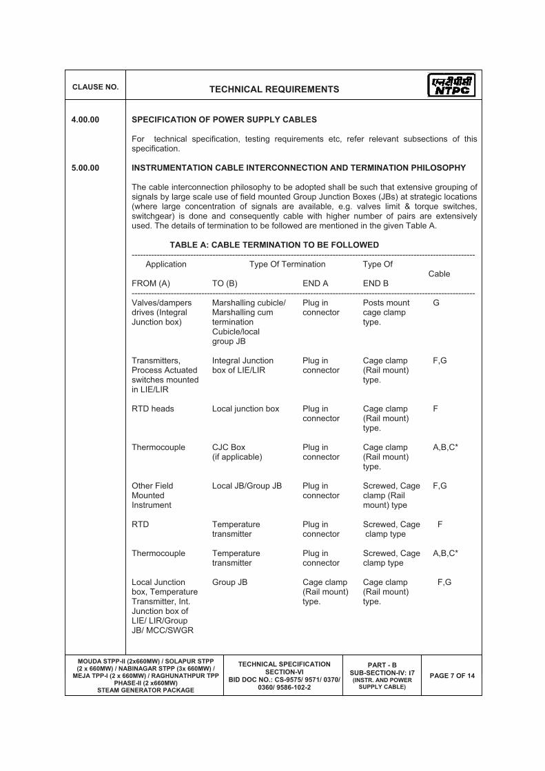
5.00.00 INSTRUMENTATION CABLE INTERCONNECTION AND TERMINATION PHILOSOPHY
The cable interconnection philosophy to be adopted shall be such that extensive grouping of signals by large scale use of field mounted Group Junction Boxes (JBs) at strategic locations (where large concentration of signals are available, e.g. valves limit & torque switches, switchgear) is done and consequently cable with higher number of pairs are extensively used. The details of termination to be followed are mentioned in the given Table A.
TABLE A: CABLE TERMINATION TO BE FOLLOWED --------------------------------------------------------------------------------------------------------------------------- Application Type Of Termination Type Of Cable FROM (A) TO (B) END A END B --------------------------------------------------------------------------------------------------------------------------- Valves/dampers Marshalling cubicle/ Plug in Posts mount G drives (Integral Marshalling cum connector cage clamp Junction box) termination type. Cubicle/local group JB Transmitters, Integral Junction Plug in Cage clamp F,G Process Actuated box of LIE/LIR connector (Rail mount) switches mounted type. in LIE/LIR
RTD heads Local junction box Plug in Cage clamp F connector (Rail mount) type.
Thermocouple CJC Box Plug in Cage clamp A,B,C* (if applicable) connector (Rail mount) type.
Other Field Local JB/Group JB Plug in Screwed, Cage F,G Mounted connector clamp (Rail Instrument mount) type
RTD Temperature Plug in Screwed, Cage F transmitter connector clamp type
Thermocouple Temperature Plug in Screwed, Cage A,B,C* transmitter connector clamp type
Local Junction Group JB Cage clamp Cage clamp F,G box, Temperature (Rail mount) (Rail mount) Transmitter, Int. type. type. Junction box of LIE/ LIR/Group JB/ MCC/SWGR

CLAUSE NO. TECHNICAL REQUIREMENTS
MOUDA STPP-II (2x660MW) / SOLAPUR STPP (2 x 660MW) / NABINAGAR STPP (3x 660MW) /
MEJA TPP-I (2 x 660MW) / RAGHUNATHPUR TPP PHASE-II (2 x660MW)
STEAM GENERATOR PACKAGE
TECHNICAL SPECIFICATION SECTION-VI
BID DOC NO.: CS-9575/ 9571/ 0370/ 0360/ 9586-102-2
PART - B SUB-SECTION-IV: I7(INSTR. AND POWER
SUPPLY CABLE)
PAGE 8 OF 14
--------------------------------------------------------------------------------------------------------------------------- Application Type Of Termination Type Of Cable FROM (A) TO (B) END A END B --------------------------------------------------------------------------------------------------------------------------- Local Junction Marshalling Cage clamp Posts mount F,G box, Temperature Cubicle/ (Rail mount) cage clamp Transmitter, Int. Marshalling cum type. type. Junction box of Termination LIE/ LIR/Group Cabinet JB/ MCC/SWGR
Marshalling Electronic system Cage clamp Plug in Internal cubicle/ cabinet Post mounted connector/ wiring Termination type. Other Cabinet System as per manufacturer's Standard
Marshalling/ UCD mounted Post mount Plug in F,G (with Termination equipments cage clamp connector/ plug-in System type. Cage clamp connector Cabinets type (rail at one mounted). end)
DDCMIS/PLC PC, Printers etc. Plug in Plug in Mfr.'s cabinets connector connector Standard
--------------------------------------------------------------------------------------------------------------------------
Notes 1. Normally 10% spare cores shall be provided when the numbers of pairs of cables are more than four pairs except for pre-fabricated cables which shall be as per manufacturer's standard.
2. For analog signals, individual pair shielding & overall shielding & for Binary signals, only overall shielding of instrumentation cables shall be provided.
3. Also refer Drg. 0000-101/102-POI-A-021.
4. *For high temperature applications only.
5. Instrument Cabling for instruments/equipments covered under subsection-IV:I3 (MAIN EQP INST SYS) shall be as per manufacturer's standard .
6.00.00 TERMINAL BLOCKS
6.01.00 All terminal blocks shall be rail mounted/post mounted, cage clamp type with high quality non-flammable insulating material of melamine suitable for working temperature of 105 deg.C. The terminal blocks in field mounted junction boxes, temperature transmitters, instrument enclosures/racks, etc., shall be suitable for cage clamp connections. The terminal blocks in Control Equipment Room logic/termination/marshalling cubicles shall be suitable for post mounted cage clamp connection at the field input end. The terminal blocks for DDCMIS input/output connections from/to SWGR/MCC, Actuators with Integral Starter (for coupling
CLAUSE NO. TECHNICAL REQUIREMENTS
MOUDA STPP-II (2x660MW) / SOLAPUR STPP (2 x 660MW) / NABINAGAR STPP (3x 660MW) /
MEJA TPP-I (2 x 660MW) / RAGHUNATHPUR TPP PHASE-II (2 x660MW)
STEAM GENERATOR PACKAGE
TECHNICAL SPECIFICATION SECTION-VI
BID DOC NO.: CS-9575/ 9571/ 0370/ 0360/ 9586-102-2
PART - B SUB-SECTION-IV: I7(INSTR. AND POWER
SUPPLY CABLE)
PAGE 9 OF 14
relays and check back signals of 11 kV and 3.3 kV auxiliaries, LT drives/valves & dampers/solenoids, CT & VT, etc.) shall be provided with built in test and disconnect facilities complete with plug, slide clamp, test socket etc. The exact type of terminal blocks to be provided by the Bidder and the technical details of the same including width etc. shall be subject to Employer's approval.
6.02.00 All the terminal blocks shall be provided complete with all required accessories including assembly rail, locking pin and section, end brackets, partitions, small partitions, test plug bolts and test plug (as specified above for SWGR connections) transparent covers, support brackets, distance sleeves, warning label, marking, etc.
6.03.00 The marking on terminal strips shall correspond to the terminal numbering on wiring diagrams. At least 20% spare unused terminals shall be provided everywhere including local junction boxes, instrument racks/enclosures, termination/marshalling cabinets, etc. All terminal blocks shall be numbered for identification and grouped according to the function. Engraved labels shall be provided on the terminal blocks.
6.04.00 For terminating each process actuated switches, drive actuators, control valves, Thermocouple, RTD, etc. in Local Junction Boxes, etc, refer Drg no. 0000-999-POI-A-065.
6.05.00 The terminal blocks shall be arranged with at least 100 mm clearance between two sets of terminal blocks and between terminal blocks and junction box walls.
6.06.00 For ensuring proper connections, Bidder shall provide suitable accessories, along with insulation sleeves. The exact connecting accessory shall be finalized as per application during detail engineering stage subject to Employer's approval without any cost repercussions.
6.07.00 Internal wiring in factory pre-wired electronic equipment cabinets may be installed according to the Bidder's standard as to wire size and method of termination or internal equipment. Terminal blocks for connection of external circuits into factory prewired electronic equipment cabinets shall meet all the requirements as specified above.
7.00.00 INTERNAL PANELS/ SYSTEM CABINETS WIRING
7.01.00 Internal panel/cabinet wiring shall be of multi-stranded copper conductor with FRLS PVC insulation without shield and outer sheath meeting the requirements of VDE 0815.
7.02.00 Wiring to door mounted devices shall be done by 19 strand copper wire provided with adequate loop lengths of hinge wire so that multiple door opening shall not cause fatigue breaking of the conductor.
7.03.00 All internal wires shall be provided with tag and identification nos. etched on tightly fitted ferules at both ends in Employer's approved format. All wires directly connected to trip devices shall be distinguished by one additional red color ferrule.
7.04.00 All external connection shall be made with one wire per termination point. Wires shall not be tapped or spliced between terminal points.
7.05.00 All floor slots of desk/panels/cabinets used for cable entrance shall be provided with removable gasketed gland plates and sealing material. Split type grommets shall be used for prefabricated cables.
7.06.00 All the special tools as may be required for solder less connections shall be provided by Bidder.

CLAUSE NO. TECHNICAL REQUIREMENTS
MOUDA STPP-II (2x660MW) / SOLAPUR STPP (2 x 660MW) / NABINAGAR STPP (3x 660MW) /
MEJA TPP-I (2 x 660MW) / RAGHUNATHPUR TPP PHASE-II (2 x660MW)
STEAM GENERATOR PACKAGE
TECHNICAL SPECIFICATION SECTION-VI
BID DOC NO.: CS-9575/ 9571/ 0370/ 0360/ 9586-102-2
PART - B SUB-SECTION-IV: I7(INSTR. AND POWER
SUPPLY CABLE)
PAGE 10 OF 14
7.07.00 Wire sizes to be utilized for internal wiring.
(i) Current (4-20 mA), low voltage 0.5 Sq.mm. signals (48V); Ammeter/Voltmeter circuit, control switches etc. for electrical system.
(ii) Power supply and internal 2.5Sq.mm. minimum (shall illumination. be as per load requirement.)
8.00.00 INSTRUMENTATION CABLE INSTALLATION AND ROUTING
8.01.00 All cables assigned to a particular duct/conduit shall be grouped and pulled in simultaneously using cable grips and suitable lubricants. Cables removed from one duct/conduit shall not be reused without approval of Employer.
8.02.00 Cables shall be segregated as per IEEE Std.-422. In vertically stacked trays, the higher voltage cable shall be in higher position and instrumentation cable shall be in bottom tier of the tray stack. The distance between instrumentation cables and those of other system shall be as follows:
From 11 kV/6.6 kV/3.3 kV tray system - 914 mm
From 415V tray system - 610 mm
From control cable tray system - 305 mm
8.03.00 Cables shall terminate in the enclosure through cable glands. All cable glands shall be properly gasketed. Fire proof sealing (to prevent ingress of dust entry and propagation of fire) shall be provided for all floor slots used for cable entrance. Compression cable glands (double for armoured and single for other cables) shall be provided.
8.04.00 All cables shall be identified by tag. Nos. provided in Employer's approved format at both the ends as well as at an interval of 5 meters.
8.05.00 Line voltage drop due to high resistance splices, terminal contacts, insulation resistance at terminal block, very long transmission line etc. shall be reduced as far as practicable.
8.06.00 The cables emanating from redundant equipment/devices shall be routed through different paths. The above segregation of cables & wiring for redundant equipments/devices shall be in accordance with IEEE-Std-422.
9.00.00 CABLE LAYING AND ACCESSORIES
9.01.00 CABLE LAYING
1 Cables shall be laid strictly in line with cable schedule.
2 Identification tags for cables.
Indelible tags to be provided at all terminations, on both sides of wall or floor crossing, on each conduit/duct/pipe entry/exit, and at every 20 m in cable trench/tray.
CLAUSE NO. TECHNICAL REQUIREMENTS
MOUDA STPP-II (2x660MW) / SOLAPUR STPP (2 x 660MW) / NABINAGAR STPP (3x 660MW) /
MEJA TPP-I (2 x 660MW) / RAGHUNATHPUR TPP PHASE-II (2 x660MW)
STEAM GENERATOR PACKAGE
TECHNICAL SPECIFICATION SECTION-VI
BID DOC NO.: CS-9575/ 9571/ 0370/ 0360/ 9586-102-2
PART - B SUB-SECTION-IV: I7(INSTR. AND POWER
SUPPLY CABLE)
PAGE 11 OF 14
3 Cable tray numbering and marking.
To be provided at every 10m and at each end of cable way & branch connection.
4 Joints for less than 250 Meters run of cable shall not be permitted.
5 Buried cable protection
With concrete slabs; Route markers at every 20 Meters along the route & at every bend.
6 Road Crossings
Cables to pass through buried high density PE pipes encased in PCC. At least 300 mm clearance shall be provided between
- HT power & LT power cables,
- LT power & LT control cables
- LT control & instrumentation cables,
Spacing between cables of same voltage grade shall be in accordance with the de-rating criteria adopted for cable sizing.
7 Segregation (physical isolation to prevent fire jumping)
a All cable associated with the unit shall be segregated from cables of other Units.
b Interplant cables of station auxiliaries and unit critical drives shall be segregated in such a way that not more than half of the drives are lost in case of single incident of fire.
8 Cable clamping
All cables laid on trays shall be neatly dressed up & suitably clamped/tied to the tray. For cables in trefoil formation, trefoil clamps shall be provided.
9 Optical fiber cables inside conduit shall be laid on cable trays wherever available and feasible. In areas where the same are required to be buried, the same shall be buried in separate trench approx.1.6 meter depth, to be laid in 2" GI/rodent proof HDPE conduits covered with sand, brick and soil along the pipe line route;
While crossing roads - to be laid in GI/rodent proof HDPE conduits with sand filling at bottom and sand, soil filling at top with cement concrete;
While crossing canals/river- to be laid in GI/rodent proof HDPE conduits within hume pipe.
9.02.00 Bidder shall supply and install all cable accessories and fittings like Light Interface Units, Surge suppressors, Opto isolators, Interface Converters, Fibre Optic Card Cage, Fibre Optic Line Driver, Repeater / Modem (for Optical Fibre Cables), cable glands, grommets, lugs, termination kits etc. on as required basis.
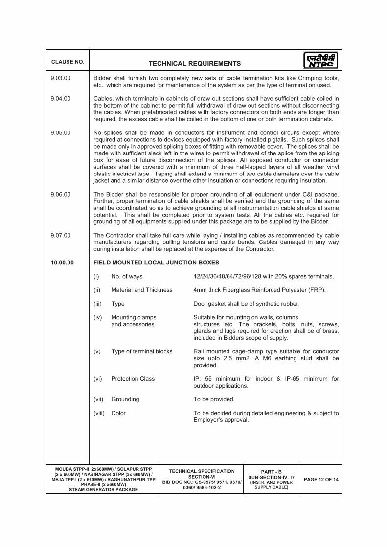
CLAUSE NO. TECHNICAL REQUIREMENTS
MOUDA STPP-II (2x660MW) / SOLAPUR STPP (2 x 660MW) / NABINAGAR STPP (3x 660MW) /
MEJA TPP-I (2 x 660MW) / RAGHUNATHPUR TPP PHASE-II (2 x660MW)
STEAM GENERATOR PACKAGE
TECHNICAL SPECIFICATION SECTION-VI
BID DOC NO.: CS-9575/ 9571/ 0370/ 0360/ 9586-102-2
PART - B SUB-SECTION-IV: I7(INSTR. AND POWER
SUPPLY CABLE)
PAGE 12 OF 14
9.03.00 Bidder shall furnish two completely new sets of cable termination kits like Crimping tools, etc., which are required for maintenance of the system as per the type of termination used.
9.04.00 Cables, which terminate in cabinets of draw out sections shall have sufficient cable coiled in the bottom of the cabinet to permit full withdrawal of draw out sections without disconnecting the cables. When prefabricated cables with factory connectors on both ends are longer than required, the excess cable shall be coiled in the bottom of one or both termination cabinets.
9.05.00 No splices shall be made in conductors for instrument and control circuits except where required at connections to devices equipped with factory installed pigtails. Such splices shall be made only in approved splicing boxes of fitting with removable cover. The splices shall be made with sufficient slack left in the wires to permit withdrawal of the splice from the splicing box for ease of future disconnection of the splices. All exposed conductor or connector surfaces shall be covered with a minimum of three half-lapped layers of all weather vinyl plastic electrical tape. Taping shall extend a minimum of two cable diameters over the cable jacket and a similar distance over the other insulation or connections requiring insulation.
9.06.00 The Bidder shall be responsible for proper grounding of all equipment under C&I package. Further, proper termination of cable shields shall be verified and the grounding of the same shall be coordinated so as to achieve grounding of all instrumentation cable shields at same potential. This shall be completed prior to system tests. All the cables etc. required for grounding of all equipments supplied under this package are to be supplied by the Bidder.
9.07.00 The Contractor shall take full care while laying / installing cables as recommended by cable manufacturers regarding pulling tensions and cable bends. Cables damaged in any way during installation shall be replaced at the expense of the Contractor.
10.00.00 FIELD MOUNTED LOCAL JUNCTION BOXES
(i) No. of ways 12/24/36/48/64/72/96/128 with 20% spares terminals.
(ii) Material and Thickness 4mm thick Fiberglass Reinforced Polyester (FRP).
(iii) Type Door gasket shall be of synthetic rubber.
(iv) Mounting clamps Suitable for mounting on walls, columns, and accessories structures etc. The brackets, bolts, nuts, screws,
glands and lugs required for erection shall be of brass, included in Bidders scope of supply.
(v) Type of terminal blocks Rail mounted cage-clamp type suitable for conductor size upto 2.5 mm2. A M6 earthing stud shall be provided.
(vi) Protection Class IP: 55 minimum for indoor & IP-65 minimum for outdoor applications.
(vii) Grounding To be provided.
(viii) Color To be decided during detailed engineering & subject to Employer's approval.

CLAUSE NO. TECHNICAL REQUIREMENTS
MOUDA STPP-II (2x660MW) / SOLAPUR STPP (2 x 660MW) / NABINAGAR STPP (3x 660MW) /
MEJA TPP-I (2 x 660MW) / RAGHUNATHPUR TPP PHASE-II (2 x660MW)
STEAM GENERATOR PACKAGE
TECHNICAL SPECIFICATION SECTION-VI
BID DOC NO.: CS-9575/ 9571/ 0370/ 0360/ 9586-102-2
PART - B SUB-SECTION-IV: I7(INSTR. AND POWER
SUPPLY CABLE)
PAGE 13 OF 14
11.00.00 CONDUITS
11.01.00 Conduits shall be generally used for interconnecting cables from field instruments to Local JB's. All rigid conduits, couplings and elbows shall be hot dipped galvanized rigid mild steel in accordance with IS: 9537 Part-I (1980) and Part-II (1981). The conduit interior and exterior surfaces shall have continuous zinc coating with an overcoat of transparent enamel lacker or zinc chromate. Flexible conduit shall be heat resistant lead coated steel, The temperature rating of flexible conduit shall be suitable for the following areas:
(i) Mills (ii) Drum (iii) Main steam, RH steam (iv) Air Heaters (v) Furnace, BFPDTs
For the remaining applications, water leak, fire and rust proof flexible GI conduits shall be provided.
11.02.00 The Bidder shall install conduits according to the general routing as approved by Employer and shall coordinate conduit locations with other works.
11.03.00 All grounding bushings within all enclosures shall be wired together and connected internally to the enclosure grounding lug or grounding bus with 8 AWG bare copper conductor. Conduit runs to individually mounted equipment shall be grounded to the Employer's cable tray grounding conductor with 12 AEG bare copper conductor. All grounding bushings, clamps and connectors shall be subject to approval of the Employer.
11.04.00 All rigid conduit fittings shall conform to the requirements of IS: 2667, 1976. Galvanized steel fitting shall be used with steel conduit. All flexible conduit fittings shall be liquid tight, galvanized steel. The end fittings shall be compatible with the flexible conduit supplied.
11.05.00 All individually mounted equipment and devices shall be connected to the supply conduit, using not more than one meter of flexible conduit adjacent to the equipment or device. Flexible conduit shall be installed in all conduit runs, which are supported by both building steel and structures subject to vibration or thermal expansion. This shall include locations where conduit supported by building steel enters or becomes supported by the turbine generator foundation and where conduit supported by building steel or foundation becomes supported by steam generator framing.
11.06.00 Special areas, such as control rooms in which external noise is to be minimized, shall have flexible conduit in conduit runs where the runs cross from the main building framing to the control room framing.
11.07.00 Conduit supports shall be furnished and installed in accordance with these specifications. Support material shall comply with the following requirements.
i) Hanger rods shall be 12 mm diameter galvanized threaded steel rods.
ii) Single conduit supports shall be one-hole cast metal straps and clamp backs unless other types are acceptable to the Employer. Multiple conduit bank supports shall be constructed of special galvanized support channels with associated conduit clips.
11.08.00 Conduit sealing, explosion proof, dust proof and other types of special fittings shall be provided as required by these specifications and shall be consistent with the area and equipment with which they are installed. Fittings installed outdoors and in damp locations

CLAUSE NO. TECHNICAL REQUIREMENTS
MOUDA STPP-II (2x660MW) / SOLAPUR STPP (2 x 660MW) / NABINAGAR STPP (3x 660MW) /
MEJA TPP-I (2 x 660MW) / RAGHUNATHPUR TPP PHASE-II (2 x660MW)
STEAM GENERATOR PACKAGE
TECHNICAL SPECIFICATION SECTION-VI
BID DOC NO.: CS-9575/ 9571/ 0370/ 0360/ 9586-102-2
PART - B SUB-SECTION-IV: I7(INSTR. AND POWER
SUPPLY CABLE)
PAGE 14 OF 14
shall be sealed and gasketed. Hazardous area fittings and conduits sealing shall conform to NEC requirements for the area classification.
11.09.00 Contractor shall provide double locknuts on all conduit terminations not provided with threaded hubs and couplings. Water tight conduit unions and rain tight conduit hubs shall be utilized for all the application which shall be exposed to weather. Moisture pockets shall be eliminated from conduits.
11.10.00 Conduits shall be securely fastened to all boxes and cabinets.
12.00.00 CABLE SUB-TRAY & SUPPORT
12.01.00 The cable sub-trays and the supporting system, to be generally used between Local/Group JBs and the main cable trays and the same shall be furnished and installed by the Contractor. It is the assembly of sections and associated fittings forming a rigid structural system used to support the cable from the equipment or instrument enclosure upto the main cable trays (trunk route).
12.02.00 The covers on the cable sub-trays shall be used for protection of cables in areas where damage may occur from falling objects, welding spark, corrosive environment, etc. & shall be electrically continuous and solidly grounded. The cable trays shall not have sharp edges, burrs or projections injurious to the insulation or outer sheath of the cables.
12.03.00 The supporting arrangement of cable tray system shall be able to withstand the weight of the cable and cable tray system. The supporting interval shall not be more than the recommended span for the above loading for the type of cable tray selected. The tray shall not overhang by more than one meter from the support at the dead end. As far as practicable the cable sub-tray system shall be supported from one side only, in order to facilitate installation and maintenance of cables.
12.04.00 The Bidder shall furnish and install the estimated quantities and sizes of sub trays/troughs including all required fittings and adaptors on as required basis.

MOUDA STPP-II (2x660MW) / SOLAPUR STPP (2 x 660MW) / NABINAGAR STPP (3x 660MW) /MEJA TPP-I (2 x 660MW) /
RAGHUNATHPUR TPP PHASE-II (2 x660MW) STEAM GENERATOR PACKAGE
TECHNICAL SPECIFICATION SECTION-VI
BID DOC NO.: CS-9575/ 9571/ 0370/ 0360/ 9586-102-2
SUB-SECTION-IV: I8
CONTROL VALVES, ACTUATORS
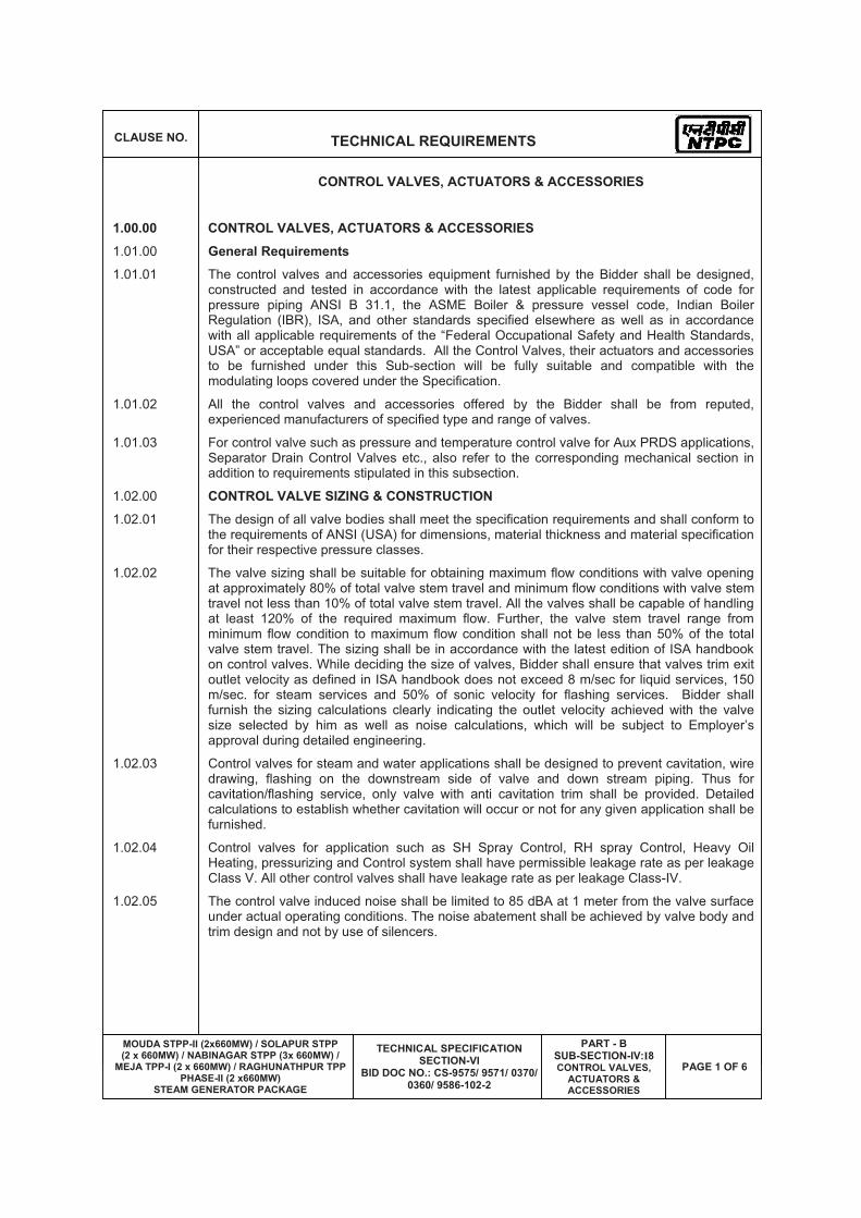
CLAUSE NO. TECHNICAL REQUIREMENTS
MOUDA STPP-II (2x660MW) / SOLAPUR STPP (2 x 660MW) / NABINAGAR STPP (3x 660MW) /
MEJA TPP-I (2 x 660MW) / RAGHUNATHPUR TPP PHASE-II (2 x660MW)
STEAM GENERATOR PACKAGE
TECHNICAL SPECIFICATION SECTION-VI
BID DOC NO.: CS-9575/ 9571/ 0370/ 0360/ 9586-102-2
PART - B SUB-SECTION-IV:I8CONTROL VALVES,
ACTUATORS & ACCESSORIES
PAGE 1 OF 6
CONTROL VALVES, ACTUATORS & ACCESSORIES
1.00.00 CONTROL VALVES, ACTUATORS & ACCESSORIES
1.01.00 General Requirements 1.01.01 The control valves and accessories equipment furnished by the Bidder shall be designed,
constructed and tested in accordance with the latest applicable requirements of code for pressure piping ANSI B 31.1, the ASME Boiler & pressure vessel code, Indian Boiler Regulation (IBR), ISA, and other standards specified elsewhere as well as in accordance with all applicable requirements of the “Federal Occupational Safety and Health Standards, USA” or acceptable equal standards. All the Control Valves, their actuators and accessories to be furnished under this Sub-section will be fully suitable and compatible with the modulating loops covered under the Specification.
1.01.02 All the control valves and accessories offered by the Bidder shall be from reputed, experienced manufacturers of specified type and range of valves.
1.01.03 For control valve such as pressure and temperature control valve for Aux PRDS applications, Separator Drain Control Valves etc., also refer to the corresponding mechanical section in addition to requirements stipulated in this subsection.
1.02.00 CONTROL VALVE SIZING & CONSTRUCTION
1.02.01 The design of all valve bodies shall meet the specification requirements and shall conform to the requirements of ANSI (USA) for dimensions, material thickness and material specification for their respective pressure classes.
1.02.02 The valve sizing shall be suitable for obtaining maximum flow conditions with valve opening at approximately 80% of total valve stem travel and minimum flow conditions with valve stem travel not less than 10% of total valve stem travel. All the valves shall be capable of handling at least 120% of the required maximum flow. Further, the valve stem travel range from minimum flow condition to maximum flow condition shall not be less than 50% of the total valve stem travel. The sizing shall be in accordance with the latest edition of ISA handbook on control valves. While deciding the size of valves, Bidder shall ensure that valves trim exit outlet velocity as defined in ISA handbook does not exceed 8 m/sec for liquid services, 150 m/sec. for steam services and 50% of sonic velocity for flashing services. Bidder shall furnish the sizing calculations clearly indicating the outlet velocity achieved with the valve size selected by him as well as noise calculations, which will be subject to Employer’s approval during detailed engineering.
1.02.03 Control valves for steam and water applications shall be designed to prevent cavitation, wire drawing, flashing on the downstream side of valve and down stream piping. Thus for cavitation/flashing service, only valve with anti cavitation trim shall be provided. Detailed calculations to establish whether cavitation will occur or not for any given application shall be furnished.
1.02.04 Control valves for application such as SH Spray Control, RH spray Control, Heavy Oil Heating, pressurizing and Control system shall have permissible leakage rate as per leakage Class V. All other control valves shall have leakage rate as per leakage Class-IV.
1.02.05 The control valve induced noise shall be limited to 85 dBA at 1 meter from the valve surface under actual operating conditions. The noise abatement shall be achieved by valve body and trim design and not by use of silencers.
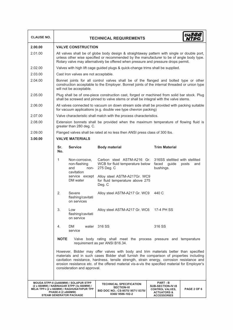
CLAUSE NO. TECHNICAL REQUIREMENTS
MOUDA STPP-II (2x660MW) / SOLAPUR STPP (2 x 660MW) / NABINAGAR STPP (3x 660MW) /
MEJA TPP-I (2 x 660MW) / RAGHUNATHPUR TPP PHASE-II (2 x660MW)
STEAM GENERATOR PACKAGE
TECHNICAL SPECIFICATION SECTION-VI
BID DOC NO.: CS-9575/ 9571/ 0370/ 0360/ 9586-102-2
PART - B SUB-SECTION-IV:I8CONTROL VALVES,
ACTUATORS & ACCESSORIES
PAGE 2 OF 6
2.00.00 VALVE CONSTRUCTION
2.01.00 All valves shall be of globe body design & straightaway pattern with single or double port, unless other wise specified or recommended by the manufacturer to be of angle body type. Rotary valve may alternatively be offered when pressure and pressure drops permit.
2.02.00 Valves with high lift cage guided plugs & quick-change trims shall be supplied.
2.03.00 Cast Iron valves are not acceptable.
2.04.00 Bonnet joints for all control valves shall be of the flanged and bolted type or other construction acceptable to the Employer. Bonnet joints of the internal threaded or union type will not be acceptable.
2.05.00 Plug shall be of one-piece construction cast, forged or machined from solid bar stock. Plug shall be screwed and pinned to valve stems or shall be integral with the valve stems.
2.06.00 All valves connected to vacuum on down stream side shall be provided with packing suitable for vacuum applications (e.g. double vee type chevron packing)
2.07.00 Valve characteristic shall match with the process characteristics.
2.08.00 Extension bonnets shall be provided when the maximum temperature of flowing fluid is greater than 280 deg. C.
2.09.00 Flanged valves shall be rated at no less then ANSI press class of 300 lbs.
3.00.00 VALVE MATERIALS
Sr. No.
Service Body material Trim Material
Carbon steel ASTM-A216 Gr. WCB for fluid temperature below 275 Deg. C
1 Non-corrosive, non-flashing and non-cavitation service except DM water
Alloy steel ASTM-A217Gr. WC9 for fluid temperature above 275 Deg. C
316SS stellited with stellited faced guide posts and bushings.
2. Severe flashing/cavitation services
Alloy steel ASTM-A217 Gr. WC9 440 C
3. Low flashing/cavitation service
Alloy steel ASTM-A217 Gr. WC6 17-4 PH SS
4. DM water service
316 SS 316 SS
NOTE Valve body rating shall meet the process pressure and temperature requirement as per ANSI B16.34.
However, Bidder may offer valves with body and trim materials better than specified materials and in such cases Bidder shall furnish the comparison of properties including cavitation resistance, hardness, tensile strength, strain energy, corrosion resistance and erosion resistance etc. of the offered material vis-a-vis the specified material for Employer’s consideration and approval.

CLAUSE NO. TECHNICAL REQUIREMENTS
MOUDA STPP-II (2x660MW) / SOLAPUR STPP (2 x 660MW) / NABINAGAR STPP (3x 660MW) /
MEJA TPP-I (2 x 660MW) / RAGHUNATHPUR TPP PHASE-II (2 x660MW)
STEAM GENERATOR PACKAGE
TECHNICAL SPECIFICATION SECTION-VI
BID DOC NO.: CS-9575/ 9571/ 0370/ 0360/ 9586-102-2
PART - B SUB-SECTION-IV:I8CONTROL VALVES,
ACTUATORS & ACCESSORIES
PAGE 3 OF 6
4.00.00 END PREPARATION
Valve body ends shall be either butt welded/socket welded, flanged (Rubber lined for condensate service) or screwed as finalized during detailed engineering and as per Employer’s approval. The welded ends wherever required shall be butt welded type as per ANSI B 16.25 for control valves of sizes 65 mm and above. For valves size 50 mm and below welded ends shall be socket welded as per ANSI B 16.11. Flanged ends wherever required shall be of ANSI pressure-temperature class equal to or greater than that of the control valve body.
5.00.00 VALVE ACTUATORS All control valves shall be furnished with pneumatic actuators except for pressure and temperature control valve for auxiliary PRDS application (electro-hydraulic / pneumatically operated) and separator drain control valve (electro-hydraulic type).The Bidder shall be responsible for proper selection and sizing of valve actuators in accordance with the pressure drop and maximum shut off pressure and leakage class requirements. The valve actuators shall be capable of operating at 60 deg.C continuously.
Valve actuators and stems shall be adequate to handle the unbalanced forces occurring under the specified flow conditions or the maximum differential pressure specified. An adequate allowance for stem force, at least 0.15 Kg/sq.cm. per linear millimeter of seating surface, shall be provided in the selection of the actuator to ensure tight seating unless otherwise specified.
The travel time of the pneumatic actuators shall not exceed 10 seconds.
6.00.00 CONTROL VALVE ACCESSORY DEVICES
6.01.00 All pneumatic actuated control valve accessories such as air locks, hand wheels/hand-jacks, limit switches, microprocessor based electronic Positioner, diffusers, external volume chambers, position transmitters (capacitance or resistance type only), reversible pilot for Positioner, tubing and air sets, solenoid valves and junction boxes etc. shall be provided as per the requirements.
7.00.00 SPECIFICATIONS FOR MICROPROCESSOR BASED ELECTRONIC POSITIONER
Input Signal 4-20 mA
Power Supply Loop Powered from the output card of Control System.
Hart Protocol Compatibility For Remote Calibration & Diagnostics (Super-Imposed HART signal on Input Signal 4-20 mA)
Electrical
Valve Position Sensing
Position Sensing (Non Contact-Type), 4-20 mA O/P Signal For Control System to be provided
Operating Temp (-)30 To 80 Deg. C
Humidity 0-95 %
Environment
Protection Class IP-65 Minimum
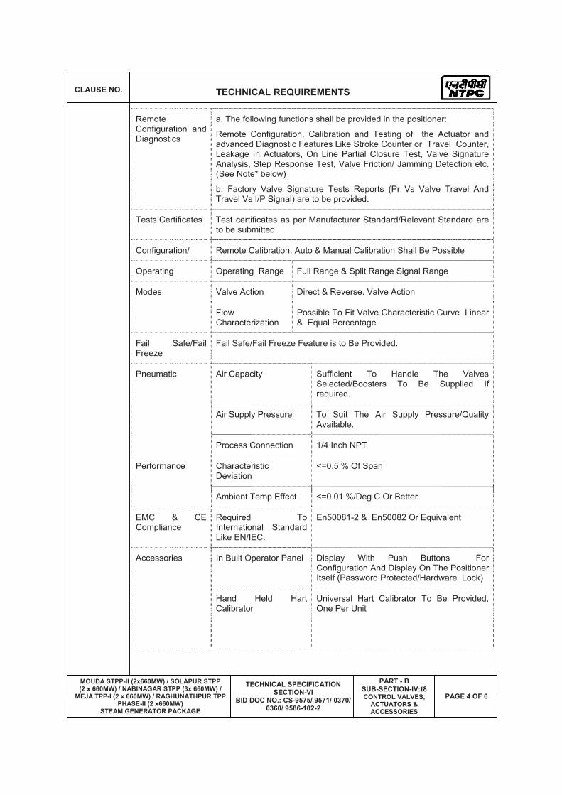
CLAUSE NO. TECHNICAL REQUIREMENTS
MOUDA STPP-II (2x660MW) / SOLAPUR STPP (2 x 660MW) / NABINAGAR STPP (3x 660MW) /
MEJA TPP-I (2 x 660MW) / RAGHUNATHPUR TPP PHASE-II (2 x660MW)
STEAM GENERATOR PACKAGE
TECHNICAL SPECIFICATION SECTION-VI
BID DOC NO.: CS-9575/ 9571/ 0370/ 0360/ 9586-102-2
PART - B SUB-SECTION-IV:I8CONTROL VALVES,
ACTUATORS & ACCESSORIES
PAGE 4 OF 6
Remote Configuration and Diagnostics
a. The following functions shall be provided in the positioner:
Remote Configuration, Calibration and Testing of the Actuator and advanced Diagnostic Features Like Stroke Counter or Travel Counter, Leakage In Actuators, On Line Partial Closure Test, Valve Signature Analysis, Step Response Test, Valve Friction/ Jamming Detection etc. (See Note* below)
b. Factory Valve Signature Tests Reports (Pr Vs Valve Travel And Travel Vs I/P Signal) are to be provided.
Tests Certificates Test certificates as per Manufacturer Standard/Relevant Standard are to be submitted
Configuration/ Remote Calibration, Auto & Manual Calibration Shall Be Possible
Operating Operating Range Full Range & Split Range Signal Range
Modes Valve Action Direct & Reverse. Valve Action
Flow Characterization
Possible To Fit Valve Characteristic Curve Linear & Equal Percentage
Fail Safe/Fail Freeze
Fail Safe/Fail Freeze Feature is to Be Provided.
Air Capacity Sufficient To Handle The Valves Selected/Boosters To Be Supplied If required.
Air Supply Pressure To Suit The Air Supply Pressure/Quality Available.
Pneumatic
Process Connection 1/4 Inch NPT
Characteristic Deviation
<=0.5 % Of Span Performance
Ambient Temp Effect <=0.01 %/Deg C Or Better
EMC & CE Compliance
Required To International Standard Like EN/IEC.
En50081-2 & En50082 Or Equivalent
In Built Operator Panel Display With Push Buttons For Configuration And Display On The Positioner Itself (Password Protected/Hardware Lock)
Accessories
Hand Held Hart Calibrator
Universal Hart Calibrator To Be Provided, One Per Unit

CLAUSE NO. TECHNICAL REQUIREMENTS
MOUDA STPP-II (2x660MW) / SOLAPUR STPP (2 x 660MW) / NABINAGAR STPP (3x 660MW) /
MEJA TPP-I (2 x 660MW) / RAGHUNATHPUR TPP PHASE-II (2 x660MW)
STEAM GENERATOR PACKAGE
TECHNICAL SPECIFICATION SECTION-VI
BID DOC NO.: CS-9575/ 9571/ 0370/ 0360/ 9586-102-2
PART - B SUB-SECTION-IV:I8CONTROL VALVES,
ACTUATORS & ACCESSORIES
PAGE 5 OF 6
Press Gauge Block For Supply & Output Pr., Filter Regulator Other Accessories Shall Be Provided As On Required Basis For Making System Complete.
Electrical Cable Entry 1/2-Npt,Side Or Bottom Entry To Avoid Water Ingress
Valves Mounting Assembly
For Sliding Stem/Rotary/Single Acting/ Double Acting On Required Basis
* Note:
Employer is providing a centralized HART management system including the HART multiplexing/interfacing system. The HART signals shall be picked up from marshalling terminals of DDCMIS (SG/TG DDCMIS as well as BOP DDCMIS), as applicable. The details of the above mentioned employer’s HART management system are as below:
The following functionalities are provided through software of the HART management system:
1. For electronic transmitters, temperature transmitters and analysers:
a. Constant scanning to monitor faults or changes to instrument configuration.
b. Employer-defined and standard calibration and configuration procedures for all transmitters.
c. Constant signal data collection facilities to maintain continuously updated records.
d. Automatic tracking of configuration changes made in the field, such as may be introduced by hand-held communicator. All configuration function associated with hand-held communicators shall be available in the system.
e. Event and log reports on screen as well as on printer.
f. Any addition/deletion of transmitter will be reported on printer and logged in hard disk.
2. For electronic positioners:
a. Remote Configuration, Calibration and Testing of the Actuator
b. Advanced Diagnostic Features Like Stroke Counter or Travel Counter, Leakage In Actuators, On Line Partial Closure Test, Valve Signature Analysis, Step Response Test, Valve Friction/ Jamming Detection etc.
Above functionalities are achieved by the Employer’s HART management system by providing industry standard softwares. If the bidder has any observations on the above, the same is to be brought out in the bid. Further, Bidder has to list out in his bid the softwares that are compatible with his electronic positioners.
8.00.00 TEST AND EXAMINATION
All valves shall be tested in accordance with the quality assurance programme agreed between the Employer and Contractor, which shall meet the requirements of IBR and other applicable codes mentioned elsewhere in the specifications. The tests shall include but not be limited to the following:
8.01.00 Non Destructive Test as per ANSI B-16.34.

CLAUSE NO. TECHNICAL REQUIREMENTS
MOUDA STPP-II (2x660MW) / SOLAPUR STPP (2 x 660MW) / NABINAGAR STPP (3x 660MW) /
MEJA TPP-I (2 x 660MW) / RAGHUNATHPUR TPP PHASE-II (2 x660MW)
STEAM GENERATOR PACKAGE
TECHNICAL SPECIFICATION SECTION-VI
BID DOC NO.: CS-9575/ 9571/ 0370/ 0360/ 9586-102-2
PART - B SUB-SECTION-IV:I8CONTROL VALVES,
ACTUATORS & ACCESSORIES
PAGE 6 OF 6
8.02.00 Hydrostatic shell test in accordance with ANSI B 16.34 prior to seat leakage test.
8.03.00 Valve closure test and seat leakage test in accordance with ANSI-B 16.34 and as per the leakage class indicated above.
8.04.00 Functional Test: The fully assembled valves including actuators control devices and accesso-ries shall be functionally tested to demonstrate times from open to close position.
8.05.00 CV Test: Please refer Cl No. 1.00.00, Sub-section-IV:I9 (Type test requirements), Control Valves.
Bidder shall furnish all the control valves under this main plant package as finalized during detailed engineering stage without any price repercussions whatsoever depending on the process requirements. All the control valves provided by the Bidder for this project shall meet the specifications requirements specified herein. Specification for control valves in this Sub-section has to be read in conjunction with other relevant Sub-sections of this speci-fication.

MOUDA STPP-II (2x660MW) / SOLAPUR STPP (2 x 660MW) / NABINAGAR STPP (3x 660MW) /MEJA TPP-I (2 x 660MW) /
RAGHUNATHPUR TPP PHASE-II (2 x660MW) STEAM GENERATOR PACKAGE
TECHNICAL SPECIFICATION SECTION-VI
BID DOC NO.: CS-9575/ 9571/ 0370/ 0360/ 9586-102-2
SUB-SECTION-IV: I9
TYPE TEST REQUIREMENTS

CLAUSE NO. TECHNICAL REQUIREMENTS
MOUDA STPP-II (2x660MW) / SOLAPUR STPP (2 x 660MW) / NABINAGAR STPP (3x 660MW) /
MEJA TPP-I (2 x 660MW) / RAGHUNATHPUR TPP PHASE-II (2 x660MW)
STEAM GENERATOR PACKAGE
TECHNICAL SPECIFICATION SECTION-VI
BID DOC NO.: CS-9575/ 9571/ 0370/ 0360/ 9586-102-2
PART - B SUB-SECTION-IV:I9
TYPE TESTS REQUIREMENTS
PAGE 1 OF 7
TYPE TEST REQUIREMENTS
1.00.00 TYPE TEST REQUIREMENTS
General Requirements
The Contractor shall furnish the type test reports of all type tests as per relevant standards and codes as well as other specific tests indicated in this specification. A list of such tests are given for various equipment in table titled 'TYPE TEST REQUIREMENT FOR C&I SYSTEMS' at the end of this chapter and under the item Special Requirement for Solid State Equipments/Systems. If the bidder proposes a different standard/code from that indicated at table 3.00.00, the same is acceptable provided the equivalence of the proposed standard is established by the bidder. For the balance equipment instrument, type tests may be conducted as per manufactures standard or if required by relevant standard.
(a) Out of the tests listed, the Bidder/ sub-vendor/ manufacturer is required to conduct certain type tests specifically for this contract (and witnessed by Employer or his authorized representative) even if the same had been conducted earlier, as clearly indicated subsequently against such tests.
(b) For the rest, submission of type test results and certificate shall be acceptable provided.
i. The same has been carried out by the Bidder/ sub-vendor on exactly the same model /rating of equipment. ( For control valves, this shall be same size, type & design).
ii. There has been no change in the components from the offered equipment & tested equipment.
iii. The test has been carried out as per the latest standards along with amendments as on the date of Bid opening.
(c) In case the approved equipment is different from the one on which the type test had been conducted earlier or any of the above grounds, then the tests have to be repeated and the cost of such tests shall be borne by the Bidder/ sub-vendor within the quoted price and no extra cost will be payable by the Employer on this account.
As mentioned against certain items, the test certificates for some of the items shall be reviewed and approved by the main Bidder or his authorized representative and the balance have to be approved by the Employer.
The schedule of conduction of type tests/ submission of reports shall be submitted and finalized during pre-award discussion.
For the type tests to be conducted, Contractor shall submit detailed test procedure for approval by Employer. This shall clearly specify test setup, instruments to be used, procedure, acceptance norms (wherever applicable), recording of different parameters, interval of recording precautions to be taken etc. for the tests to be carried out.
The Bidder shall indicate in the relevant BPS schedule, the cost of the type test for each item only for which type tests are to be conducted specifically for this project. The cost shall only

CLAUSE NO. TECHNICAL REQUIREMENTS
MOUDA STPP-II (2x660MW) / SOLAPUR STPP (2 x 660MW) / NABINAGAR STPP (3x 660MW) /
MEJA TPP-I (2 x 660MW) / RAGHUNATHPUR TPP PHASE-II (2 x660MW)
STEAM GENERATOR PACKAGE
TECHNICAL SPECIFICATION SECTION-VI
BID DOC NO.: CS-9575/ 9571/ 0370/ 0360/ 9586-102-2
PART - B SUB-SECTION-IV:I9
TYPE TESTS REQUIREMENTS
PAGE 2 OF 7
be payable after the respective type tests are conducted in presence of authorized representative of Employer. If a test is waived off, then the cost shall not be payable.
2.00.00 SPECIAL REQUIREMENT FOR SOLID STATE EQUIPMENTS/ SYSTEMS
The minimum type test reports, over and above the requirements of above clause, which are to be submitted for each of the major C&I systems shall be as indicated below:
i) Surge Withstand Capability ( SWC) for Solid State Equipments/ Systems
All solid state systems/ equipments shall be able to withstand the electrical noise and surges as encountered in actual service conditions and inherent in a power plant. All the solid state systems/ equipments shall be provided with all required protections that needs the surge withstand capability as defined in ANSI 37.90.1/ IEEE-472. Hence, all front end cards which receive external signals like Analog input & output modules, Binary input & output modules etc. including power supply, data highway, data links shall be provided with protections that meets the surge withstand capability as defined in ANSI 37.90.1/ IEEE-472. Complete details of the features incorporated in electronics systems to meet this requirement, the relevant tests carried out, the test certificates etc. shall be submitted along with the proposal. As an alternative to above, suitable class of EN 61000-4-12 which is equivalent to ANSI 37.90.1/ IEEE-472 may also be adopted for SWC test.
ii) Dry Heat test as per IEC-68-2-2 or equivalent.
iii) Damp Heat test as per IEC-68-2-3 or equivalent.
iv) Vibration test as per IEC-68-2-6 or equivalent.
v) Electrostatic discharge tests as per EN 61000-4-2 or equivalent. vi) Radio frequency immunity test as per EN 61000-4-6 or equivalent.
vii) Electromagnetic Field immunity as per EN 61000-4-3 or equivalent.
Test listed at item no. v, vi, vii, above are applicable for electronic cards only as defined under item (i) above.
3.00.00 TYPE TEST REQUIREMENT FOR C&I SYSTEMS
Sl. No
Item Test Requirement
Standard Test To Be SpecificallyConducted
NTPC’s Approval Req. On Test Certificate
Col 1 Col 2 Col 3 Col 4 Col 5 Col 6
1 Elect. Metering instruments
As per standard (col 4)
IS-1248 No Yes
2 Thermocouple Degree of protection test
IS-2147 No No

CLAUSE NO. TECHNICAL REQUIREMENTS
MOUDA STPP-II (2x660MW) / SOLAPUR STPP (2 x 660MW) / NABINAGAR STPP (3x 660MW) /
MEJA TPP-I (2 x 660MW) / RAGHUNATHPUR TPP PHASE-II (2 x660MW)
STEAM GENERATOR PACKAGE
TECHNICAL SPECIFICATION SECTION-VI
BID DOC NO.: CS-9575/ 9571/ 0370/ 0360/ 9586-102-2
PART - B SUB-SECTION-IV:I9
TYPE TESTS REQUIREMENTS
PAGE 3 OF 7
3 RTD As per standard (col 4)
IEC-60751 No No
4 Electronic transmitter
As per standard (col 4)
BS-6447 / IEC-60770
No Yes
5 E/P converter As per standard (col 4)
Mfr.standard
No Yes
6 Instrumentation Cables Twisted & Shielded
-Conductor Resistance test
VDE-0815 No Yes
Diameter test IS-10810 No Yes
Tin Coating test (Persul-phate test)
IS-8130 No Yes
-Insulation Loss of mass VDE 0472 No Yes
Ageing in air ovens**
VDE 0472 No Yes
Tensile strength and elongation test before and after ageing**
VDE 0472 No Yes
Heat shock VDE 0472 No Yes
Hot deformation
VDE 0472 No Yes
Shrinkage VDE 0472 No Yes
Bleeding & blooming
IS-10810 No Yes
-Inner sheath***
Loss of mass VDE 0472 No Yes
Heat shock VDE 0472 No Yes
Cold bend/ cold impact test
VDE 0472 No Yes
Hot deformation
VDE 0472 No Yes
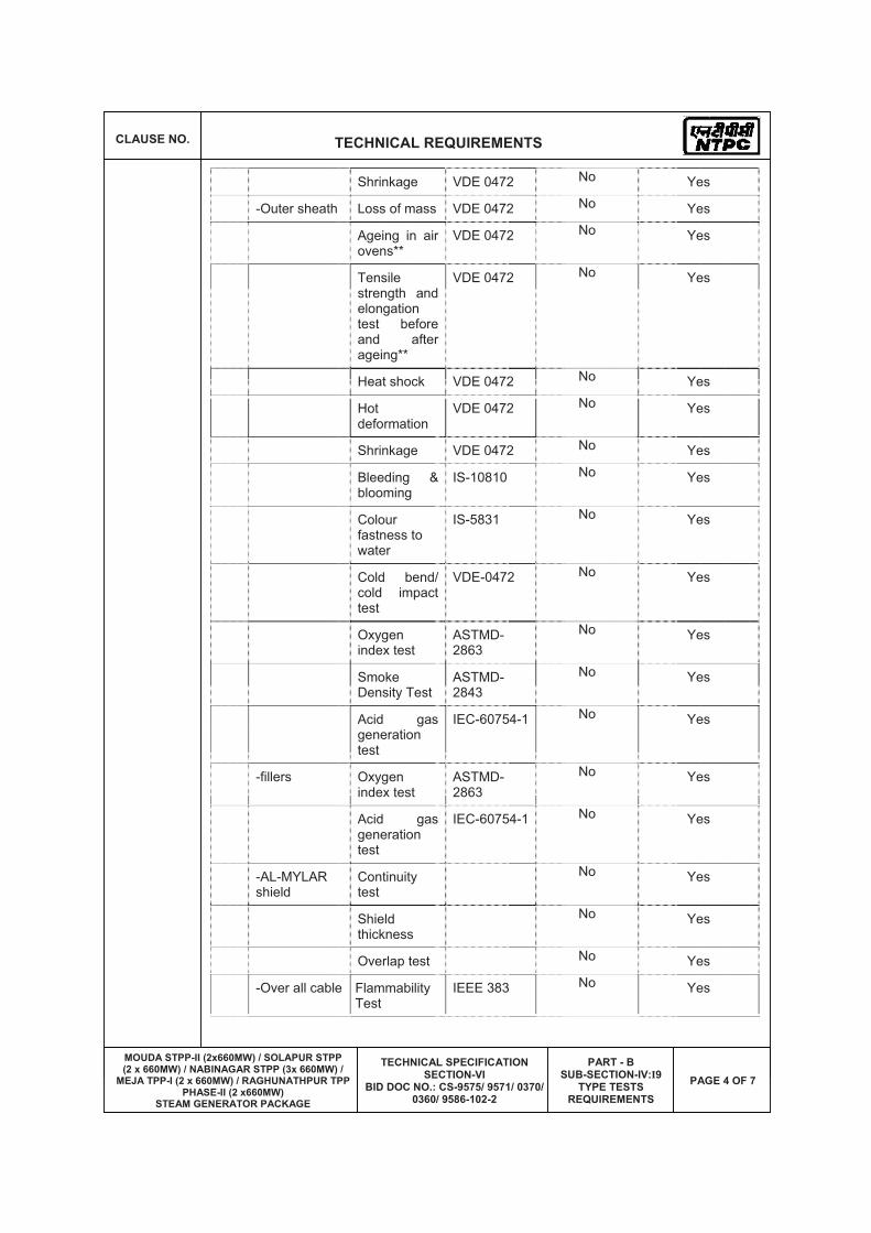
CLAUSE NO. TECHNICAL REQUIREMENTS
MOUDA STPP-II (2x660MW) / SOLAPUR STPP (2 x 660MW) / NABINAGAR STPP (3x 660MW) /
MEJA TPP-I (2 x 660MW) / RAGHUNATHPUR TPP PHASE-II (2 x660MW)
STEAM GENERATOR PACKAGE
TECHNICAL SPECIFICATION SECTION-VI
BID DOC NO.: CS-9575/ 9571/ 0370/ 0360/ 9586-102-2
PART - B SUB-SECTION-IV:I9
TYPE TESTS REQUIREMENTS
PAGE 4 OF 7
Shrinkage VDE 0472 No Yes
-Outer sheath Loss of mass VDE 0472 No Yes
Ageing in air ovens**
VDE 0472 No Yes
Tensile strength and elongation test before and after ageing**
VDE 0472 No Yes
Heat shock VDE 0472 No Yes
Hot deformation
VDE 0472 No Yes
Shrinkage VDE 0472 No Yes
Bleeding & blooming
IS-10810 No Yes
Colour fastness to water
IS-5831 No Yes
Cold bend/ cold impact test
VDE-0472 No Yes
Oxygen index test
ASTMD-2863
No Yes
Smoke Density Test
ASTMD-2843
No Yes
Acid gas generation test
IEC-60754-1 No Yes
-fillers Oxygen index test
ASTMD-2863
No Yes
Acid gas generation test
IEC-60754-1 No Yes
-AL-MYLAR shield
Continuity test
No Yes
Shield thickness
No Yes
Overlap test No Yes
-Over all cable Flammability Test
IEEE 383 No Yes
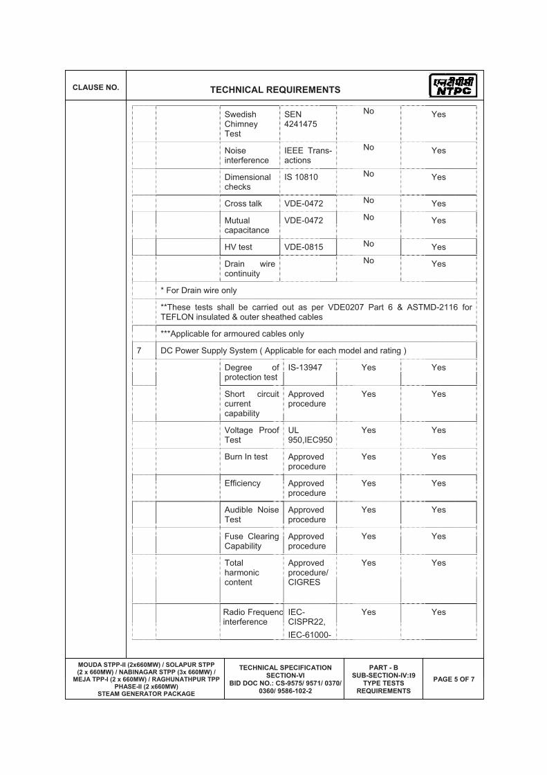
CLAUSE NO. TECHNICAL REQUIREMENTS
MOUDA STPP-II (2x660MW) / SOLAPUR STPP (2 x 660MW) / NABINAGAR STPP (3x 660MW) /
MEJA TPP-I (2 x 660MW) / RAGHUNATHPUR TPP PHASE-II (2 x660MW)
STEAM GENERATOR PACKAGE
TECHNICAL SPECIFICATION SECTION-VI
BID DOC NO.: CS-9575/ 9571/ 0370/ 0360/ 9586-102-2
PART - B SUB-SECTION-IV:I9
TYPE TESTS REQUIREMENTS
PAGE 5 OF 7
Swedish Chimney Test
SEN 4241475
No Yes
Noise interference
IEEE Trans-actions
No Yes
Dimensional checks
IS 10810 No Yes
Cross talk VDE-0472 No Yes
Mutual capacitance
VDE-0472 No Yes
HV test VDE-0815 No Yes
Drain wire continuity
No Yes
* For Drain wire only
**These tests shall be carried out as per VDE0207 Part 6 & ASTMD-2116 for TEFLON insulated & outer sheathed cables
***Applicable for armoured cables only
7 DC Power Supply System ( Applicable for each model and rating )
Degree of protection test
IS-13947 Yes Yes
Short circuit current capability
Approved procedure
Yes Yes
Voltage Proof Test
UL950,IEC950
Yes Yes
Burn In test Approved procedure
Yes Yes
Efficiency Approved procedure
Yes Yes
Audible Noise Test
Approved procedure
Yes Yes
Fuse Clearing Capability
Approved procedure
Yes Yes
Totalharmonic content
Approved procedure/CIGRES
Yes Yes
Radio Frequencyinterference
IEC- CISPR22, IEC-61000-
Yes Yes
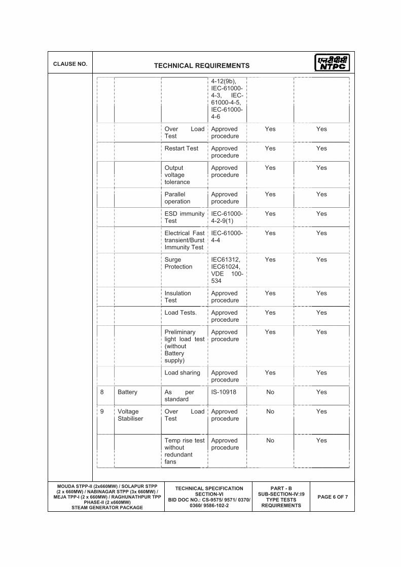
CLAUSE NO. TECHNICAL REQUIREMENTS
MOUDA STPP-II (2x660MW) / SOLAPUR STPP (2 x 660MW) / NABINAGAR STPP (3x 660MW) /
MEJA TPP-I (2 x 660MW) / RAGHUNATHPUR TPP PHASE-II (2 x660MW)
STEAM GENERATOR PACKAGE
TECHNICAL SPECIFICATION SECTION-VI
BID DOC NO.: CS-9575/ 9571/ 0370/ 0360/ 9586-102-2
PART - B SUB-SECTION-IV:I9
TYPE TESTS REQUIREMENTS
PAGE 6 OF 7
4-12(9b), IEC-61000-4-3, IEC-61000-4-5, IEC-61000-4-6
Over Load Test
Approved procedure
Yes Yes
Restart Test Approved procedure
Yes Yes
Output voltage tolerance
Approved procedure
Yes Yes
Parallel operation
Approved procedure
Yes Yes
ESD immunity Test
IEC-61000-4-2-9(1)
Yes Yes
Electrical Fast transient/Burst Immunity Test
IEC-61000-4-4
Yes Yes
Surge Protection
IEC61312, IEC61024, VDE 100-534
Yes Yes
Insulation Test
Approved procedure
Yes Yes
Load Tests. Approved procedure
Yes Yes
Preliminary light load test (without Battery supply)
Approved procedure
Yes Yes
Load sharing Approved procedure
Yes Yes
8 Battery As per standard
IS-10918 No Yes
9 Voltage Stabiliser
Over Load Test
Approved procedure
No Yes
Temp rise test without redundant fans
Approved procedure
No Yes

CLAUSE NO. TECHNICAL REQUIREMENTS
MOUDA STPP-II (2x660MW) / SOLAPUR STPP (2 x 660MW) / NABINAGAR STPP (3x 660MW) /
MEJA TPP-I (2 x 660MW) / RAGHUNATHPUR TPP PHASE-II (2 x660MW)
STEAM GENERATOR PACKAGE
TECHNICAL SPECIFICATION SECTION-VI
BID DOC NO.: CS-9575/ 9571/ 0370/ 0360/ 9586-102-2
PART - B SUB-SECTION-IV:I9
TYPE TESTS REQUIREMENTS
PAGE 7 OF 7
Input voltage variation test
Approved procedure
No Yes
10 DDCMIS
BMS Safety requirements
VDE0116 Sec 8.7
No Yes
11 Conductivity Type Level Switch
Degree of protection test
IS-2147 No No
12 Local Gauges Degree of protection test
IS-2147 No No
13 Process actuated Switches
Degree of protection test
IS-2147 No No
14 Control Valves CV test ISA 75.02 No Yes
15 PLCs As per standard
IEC 1131 No No
16 LIE / LIR Degree of protection test
IS-2147 Yes Yes
17 Flue gas O2 analyser, other Flue Gas analysers
Degree of protection test
IS-2147 No Yes
18 Flow Nozzle Orifice plates
Calibration ASME PTC BS 1042
Yes Yes
Note:
Type Tests are to be conducted only for the items, which are being supplied as a part of this Package.


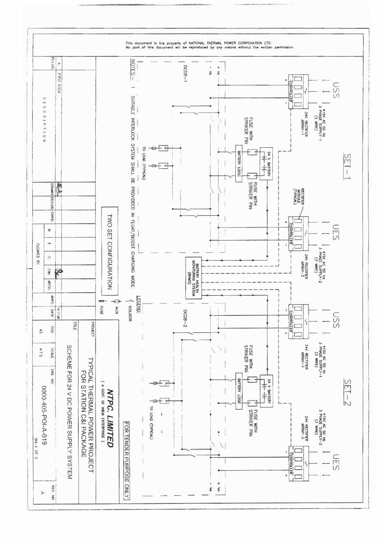
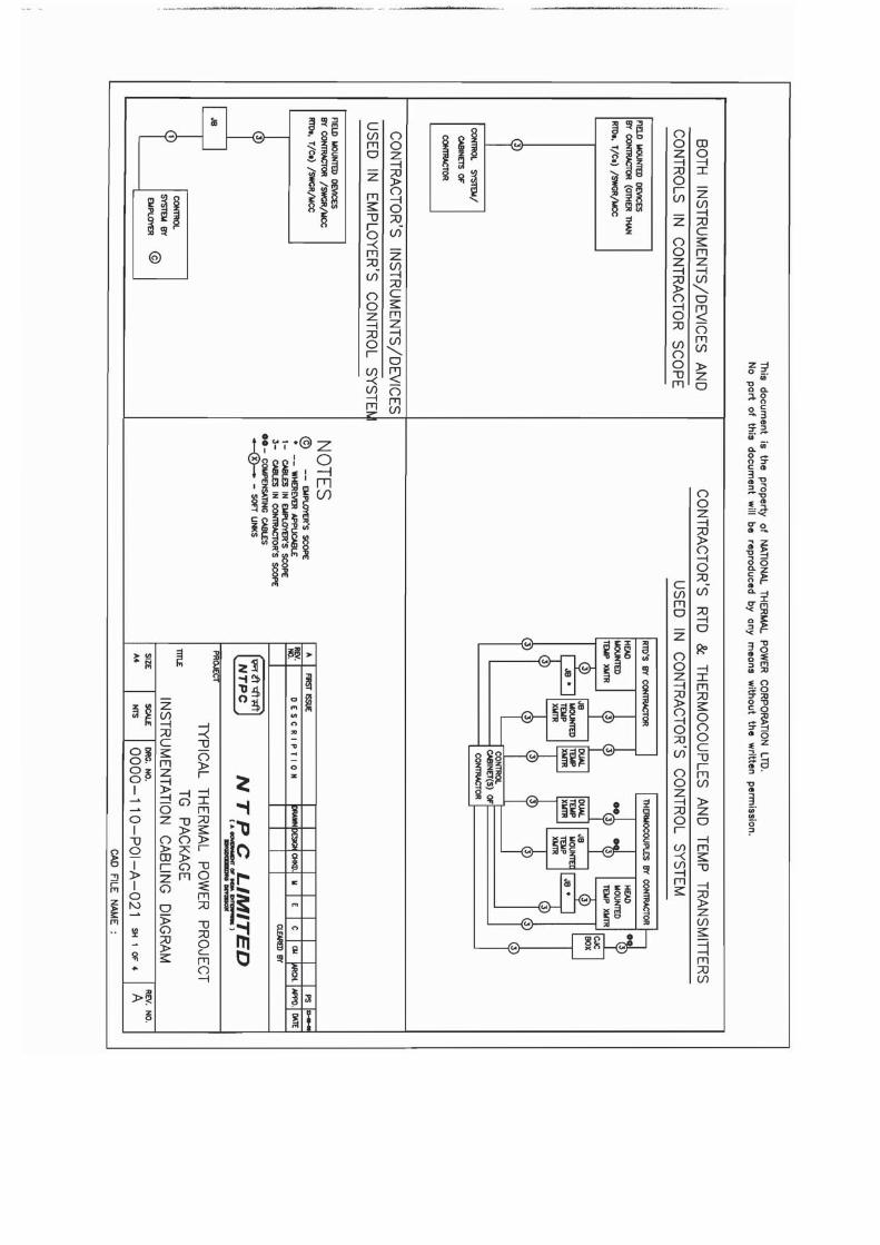


BHEL DOCUMENTS NO.: PE-TS-385-160-A001
VOLUME II-B
SECTION -D
2X600MW MAUDA STPP STAGE-II REV. NO. 00 DATE: Page
BHEL – PS - PPEI: NOIDA, SECTOR-16A, U.P. – 201301
TITLE:
TECHNICAL SPECIFICATION FOR MILL REJECT HANDLING SYSTEM
VOLUME – II B
SECTION-D
STANDARD TECHNICAL REQUIREMENTS
BHEL DOCUMENTS NO.: PE-TS-385-160-A001
VOLUME II-B
SECTION -D
REV. NO. 00 DATE: Page
BHEL – PS - PPEI: NOIDA, SECTOR-16A, U.P. – 201301
TITLE:
TECHNICAL SPECIFICATION FOR AIR RECEIVER
1.0 GENERAL This standard specification covers the design, material of construction,
features, manufacture, inspection & testing at VENDOR’S and/or his sub-vendors’ works, suitable painting and packing requirements of air receiver
2.0 CODES & STANDARDS
. As far as possible, the design, manufacture and performance of air
receivers shall be in accordance with the latest applicable Indian/British/American/DIN standards.
The latest editions of the following shall be followed in particular: IS: 2825 – Code for unfired pressure vessels ASME – Section-VIII, Division-1 BS – 487-Fusion welded steel air receivers IS: 7938 – Air receivers for compressed air installation The materials of the various components shall conform to applicable
IS/BS/ASTM/DIN standards.
3.0 DESIGN AND CONSTRUCTION
3.1 The air receivers shall be vertical self-supporting cylindrical vessels with supporting stands for resting on the civil foundation.
3.2 Other design parameters and design internal pressure of the receiver shall
be as per the data specification sheet, if any, enclosed. The receiver shall be designed as per IS:7938.
3.3 Receivers shall be of welded construction with a minimum number of
joints. Longitudinal seams in adjacent section of shell shall not be in the same line.
3.4 Receivers shall be provided with gasket inspection openings. Receivers
below 500 mm diameter shall have at least two inspection holes. For receivers of larger diameter, manhole of minimum 450 mm diameter shall be provided. These openings shall be placed as far as possible from any welded seam and in no instance shall pierce any seam.
3.5 All welding shall be performed in accordance with relevant codes. Filler
material that will deposit weld metal with a composition and structure as near as that of the material being welded shall be used. All welding electrodes shall be got approved by the Owner. The electrodes shall be

BHEL DOCUMENTS NO.: PE-TS-385-160-A001
VOLUME II-B
SECTION -D
REV. NO. 00 DATE: Page
BHEL – PS - PPEI: NOIDA, SECTOR-16A, U.P. – 201301
TITLE:
TECHNICAL SPECIFICATION FOR AIR RECEIVER
dried in ovens immediately before use to ensure freedom from porosity. All the circumferential and longitudinal butt welds of the air receiver shall be subjected to spot radiography. Tee joints and dished welding shall be subjected to 100% radiography.
3.6 All other welding on the air receiver, including filet weld and nozzle
connection shall be DP tested as per IS: 2825 (Para 8.7.11).
3.7 Each finished receiver complete with all welded attachments shall be hydraulically tested at 150% of the design pressure. The test pressure shall be maintained for at least 30 minutes. All joints shall be gentle hammered during the test.
3.8 Receivers shall be provided with relief valve of the capacity and set
pressure of the same at least 10% above working pressure. The spring in the relief valve in service for pressure up to and including 250 psi shall not be reset for any pressure more than 10% above or below the design set pressure. For higher pressures, the spring shall not be reset for any pressure more or below 5% design set pressure.
3.9 Each air receiver shall be complete with drain connection of 25 mm NB
with a trap station consisting of a trap, strainer, isolation and bypass valves.
3.10 The receiver shall be provided with necessary number of nozzles. The
orientation of the nozzles shall be subjected to the approval of the Owner.
3.11 Local instruments like pressure gauge, switch and temp. gauge of suitable range shall be supplied. Please refer specification for conveying air compressor for other instrumentation required.
3.12 The vendor will have all welding procedures & welders qualified in
accordance with the relevant codes prior to commencing any welding at the works. These tests shall be witnessed by customer/client representative.

BHEL DOCUMENTS NO.: PE-TS-385-160-A001
VOLUME II-B
SECTION -D
REV. NO. 00 DATE: Page
BHEL – PS - PPEI: NOIDA, SECTOR-16A, U.P. – 201301
TITLE:
TECHNICAL SPECIFICATION FOR CHAIN PULLEY BLOCK & MONORAIL
1.0.0 GENERAL
This specification covers the design, manufacture, assembly, inspection and
testing at manufacturer’s and/or his sub-constructor's works of hand operated
chain pulley block.
2.0.0 CODES AND STANDARDS
The design, manufacture, inspection and testing and performance of hand
operated chain pulley blocks shall confirm to latest editions of the following
standards: -
a) IS: 3832 Specification for hand operated chain pulley block
b) IS 807: 1976 Codes of Practice for Design, Manufacture, Erection and
Testing (Structural Portion) of cranes and hoists
c) IS: 3109(Part II) Calibrated load chain for pulley blocks and other lifting
appliances
d) IS: 2429(Part II) Calibrated hand chain for pulley blocks and other lifting
appliances
e) IS: 4460 Method for rating of machine cut spur and helical gears
f) Material Specification IS or approved
3.0.0 EQUPIMENT
3.1.0 CHAIN PULLEY BLOCK
The block shall be so designed that all components shall withstand without
failure, an application to the block of a load equal to at least four times the
working load limit.
3.1.1 Frame
BHEL DOCUMENTS NO.: PE-TS-385-160-A001
VOLUME II-B
SECTION -D
REV. NO. 00 DATE: Page
BHEL – PS - PPEI: NOIDA, SECTOR-16A, U.P. – 201301
TITLE:
TECHNICAL SPECIFICATION FOR CHAIN PULLEY BLOCK & MONORAIL
Frame shall be robust in design and of welded construction. The frame shall
be selected in such a way that head room requirement is minimum. Frame
shall maintain alignment under all expected conditions of services.
3.1.2 Chain
The load chain shall be electrically welded, accurately calibrated, and pitched
arid polished conforming to IS: 6216 Grade 80 as specified in data sheet ‘A’.
The hand chain shall also be electrically welded, calibrated, pitched and
polished and shall conform to IS: 2429 (Part II) grade 30. The length of chain
and link dimension shall be as per IS: 3832.
3.1.3 Hook
The forged hook shall be properly heat-treated and so designed that in loaded
condition, it is free to swivel without twisting the load chain. The hook shall
conform to IS: 3815.
3.1.4 Reduction Gear
The reduction gear shall be spur or worm/worm wheel type. The spur gear
and worm shall be of high-grade carbon steel and heat treated. The worm
wheel shall be of bronze. A detachable steel cover shall be provided for total
enclosure of the gear train and ample lubrication to be provided.
3.1.5 Brakes
Brakes shall be of screw friction disc type self-actuating or any other approved
type as per manufacturer’s standard practice. Brake capacity shall be ample
and humid atmosphere shall not affect materials used. The brake shall
prevent self lowering of load and arrest and sustain load in all working
positions. The load brake shall also allow smooth lowering of the load without
serious overheating which may impair sufficient working of block
3.1.6 Bearing
Bearing used shall be as per guidelines laid down in IS: 3832.
3.1.7 Wheel
The load chain wheel shall be made of heavy duty malleable casting and shall
be designed to ensure, effective operation of the chain. Load chain, wheel
shall be mounted on two ball bearings. Hand chain wheel shall be made from
malleable casting/pressed sheet steel. The idler wheel shall be so shaped as
BHEL DOCUMENTS NO.: PE-TS-385-160-A001
VOLUME II-B
SECTION -D
REV. NO. 00 DATE: Page
BHEL – PS - PPEI: NOIDA, SECTOR-16A, U.P. – 201301
TITLE:
TECHNICAL SPECIFICATION FOR CHAIN PULLEY BLOCK & MONORAIL
to avoid the twisting of the chain during operation. The P.C.D of idler wheels
shall be such that the bending action of the link is avoided. The hand chain
wheel shall be provided with flanges and designed to ensure effective
operation with hand chain.
3.1.8 Other components
All other components of chain pulley block such as anchorage, guide, pawl,
stripper etc. shall be designed and provided as per IS: 3832.
3.2.0 MONORAIL TROLLEY
Monorail trolley shall be provided if called for in the enclosed Data Sheet—A.
Monorail trolley frame shall be of heavy section rolled steel, held together by
bolts. Wheels shall be of high grade cast iron mounted on ball bearings. Axles
and shafts shall be of carbon steel, accurately machined and suitably
supported. The trolley shall be suitable for variations in I section beams. The
trolley shall be geared travel type.
The hand chain required for trolley travel shall be as per clause 3.1.2 of this
specification.
Hand chain wheel shall be as per clause 3.1.7 of this specification.
4.0.0 INSPECTION AND TESTING
The scope of inspection shall include but not limited to the following:
a) Material identification/co-relation for important items like hook, load chain,
hand chain, wheels, nut and pawl etc.
b) Hardness for pawl and ratchet
c) Dye penetration test for hooks
d) Operational test including operational effort, velocity ratio etc,
e) Proof load test up to 1.5 times of working load limit.
f) Dimensional check of hook
g) Marking
DATASHEET S. No.
Parameter Description
1 Capacity (In Kg) Suitable for lifting the heaviest load but not less than One (1) ton
BHEL DOCUMENTS NO.: PE-TS-385-160-A001
VOLUME II-B
SECTION -D
REV. NO. 00 DATE: Page
BHEL – PS - PPEI: NOIDA, SECTOR-16A, U.P. – 201301
TITLE:
TECHNICAL SPECIFICATION FOR CHAIN PULLEY BLOCK & MONORAIL
2 Service condition Class II outdoor 3 No. of CPB 1 4 Lift (m) To suit bunker height and equipment on bunker
roof top to be handled. 5 Type of suspension Travelling Trolley 6 Head Room Minimum permissible 7 Type of gear in CPB Spur Gear 8 Type of bearing Ball/Roller 9 Grade of Load Chain Alloy Steel /Gr 80 10 Grade of Hand Chain Steel / Gr. 30 11 Factor of Safety As per Relevant IS
BHEL DOCUMENTS NO.: PE-TS-385-160-A001
VOLUME II-B
SECTION -D
REV. NO. 00 DATE: Page
BHEL – PS - PPEI: NOIDA, SECTOR-16A, U.P. – 201301
TITLE:
TECHNICAL SPECIFICATION FOR CONVEYING AIR COMPRESSOR
1.0 GENERAL This standard specification covers the design, material construction
features, manufacture, inspection & testing at VENDOR’S and / or his sub vendors works suitable painting and packing requirements of air compressor with drive.
2.0 CODES & STANDARDS
2.1 The design, manufacture, inspection & testing of air compressor as
specified hereinafter shall comply with the requirements of the latest applicable Indian/British American Standards. The following standards/codes shall be following in particular.
a) IS:5456 Code of practice for testing pf positive displacement type
air compressors and exhauster.
b) IS:5727 Glossary of terms relating to compressors and exhauster.
c) IS:6206 Guide for selection, installation and maintenance of air compressors.
2.2 The material of various components shall conform as specified in Data
Sheet-A and where not specified, the material shall conform to the applicable IS / BS / ASTM / DIN Standards.
2.3 In case of any conflict between the above mentioned standards / codes
and specification, the stipulations in the technical specification shall prevail. In case of any further conflict the same shall be referred to purchaser’s engineer for clarification whose decision shall be final & binding.
3.0 DESIGN AND CONSTRUCTION
3.1 Air Compressors of reciprocating type shall be designed for continuous
operation to satisfy the conveying air requirement for fail safe operation.
3.2 The design, manufacture and performance of air compressors shall comply with the requirements of latest applicable Indian / British American / DIN standards.
3.3 The compressors shall be water cooled, non lubricated type along with all
accessories as specified in the data sheet - A. Intercoolers/ aftercoolers, if provided, shall also be of water cooled, shell – tube construction.
3.4 The compressors shall be designed to ensure trouble free operation with
min. vibration and noise. Multiple cylinders, if employed, shall be arranged in such a way as to ensure min. unbalance.

BHEL DOCUMENTS NO.: PE-TS-385-160-A001
VOLUME II-B
SECTION -D
REV. NO. 00 DATE: Page
BHEL – PS - PPEI: NOIDA, SECTOR-16A, U.P. – 201301
TITLE:
TECHNICAL SPECIFICATION FOR CONVEYING AIR COMPRESSOR
3.5 The wall thickness of the compressor cylinder shall be selected to
withstand highest internal pressure and at the same time shall allow a number of reborings.
3.6 The crank case shall be provided with oil level dip stick, breather and drain
plug.
3.7 Any oil adhering to the piston rod shall be wiped-off by suitable wiper ring, suitable collars shall also be fixed on the piston rod between the packing and wiper rings so that any trickling oil flow can be stopped from moving towards the cylinder.
3.8 Suction and discharge valves shall be suitable for quick opening and
closing in conformity with the rotating speed of the crank shaft. Valves shall have large effective areas permitting low air velocity along with cushioning arrangement to minimise shock. Valve discs shall be of stainless steel (containing 15% or more chromium) heat treated, tempered and ground. The valve seats, guides & springs shall be of hardened stainless steel.
3.9 Crankshaft, crank pin piston pin bearings shall be of antifriction or journal
type depending on manufacturer’s standard practice.
3.10 Splash or forced feed type of lubrication shall be provided for all bearings and sliding components.
3.11 The air receiver shall be sized that even in the event of total stoppage of
air flow from the compressor, operation of conveying is not stopped for 2 cycle time duration.
3.12 Drive motor shall be connected to the air compressor directly or through V-
belt or any other suitable type of power transmission system as specified in the data sheets. Shafts should be coupled through heavy-duty flexible coupling in case of direct drive.
3.13 The power rating of the drive shall be selected such that a min. margin of
15% is available over the total input power required at compressor drive shaft at the rated condition. Total input power shall include air compression power plus any power consumed in auxiliaries etc., (if any), when the driver is not directly coupled to compressor, due account shall be made for losses in power transmission in addition to the above 15% extra margin.
4.0 MATERIAL OF CONSTRUCTION
The material of construction for various parts of package air compressors
shall be as follows:-

BHEL DOCUMENTS NO.: PE-TS-385-160-A001
VOLUME II-B
SECTION -D
REV. NO. 00 DATE: Page
BHEL – PS - PPEI: NOIDA, SECTOR-16A, U.P. – 201301
TITLE:
TECHNICAL SPECIFICATION FOR CONVEYING AIR COMPRESSOR
a) Compressor cylinder :CI ,IS- 210, grade FG-260
b) Piston :Aluminum c) Piston rod :EN-8 as per BS -970 d) Connecting rod :Forged steel as per IS-1875 Cl IV e) Piston ring :Teflon with 25-30% carbon. f) Crank case :CI , IS-210 Grade FG-260 g) Suction and delivery valves :S.S as per EN-56 of BS-970 h) Air receiver :MS as per IS (2062)
i) For other parts :As per latest IS/BS/ASTM/AIS/ equivalent standards depending upon the parts
5.0 INSTRUMENTATION AND ACCESSORIES
The conveying air compressor and drive shall be supplied completed with the
following instrumentation and accessories as minimum. a) Discharge air pressure gauge b) Pressure switch to control actuation of compressor drive motor. c) Starter for drive motor. d) Pressure relief valve e) Drain valve f) Delivery valve
6.0 INSPECTION & TESTING
6.1 The manufacturer shall conduct all tests to ensure that the equipment finished shall conform to the requirements of this specification and in compliance with requirements of applicable codes & standard.
6.2 All materials used for conveying air compressor and drive shall be of
tested quality. Materials shall be tested as per the relevant standards and test certificates shall be made available to the purchaser.
6.3 Test at Shop:
a) All pressure parts shall be subjected to hydraulic testing at a
pressure twice the maximum design pressure or 150% of design pressure whichever is more for a period not less than one (1) hour.
b) Assembled receiver shall he hydraulically tested at a pressure
twice the maximum working pressure or 150% of the design pressure and the test pressure shall be maintained for at least 30 minutes. All joints shall be gently hammered during the test.
c) Pneumatic test at design pressure shall also be carried out.
7.0 PAINTING
BHEL DOCUMENTS NO.: PE-TS-385-160-A001
VOLUME II-B
SECTION -D
REV. NO. 00 DATE: Page
BHEL – PS - PPEI: NOIDA, SECTOR-16A, U.P. – 201301
TITLE:
TECHNICAL SPECIFICATION FOR CONVEYING AIR COMPRESSOR
7.1 All parts of air compressors with drive shall be painted as specified in Data
Sheet-A or as per the specification furnished elsewhere. 7.2 Before transportation of the equipment necessary cleaning, flushing etc,
shall be done shop coats of rust inhibiting paints, lacquers etc., shall be applied to various parts as necessary.

BHEL DOCUMENTS NO.: PE-TS-385-160-A001
VOLUME II-B
SECTION -D
REV. NO. 00 DATE:
Page
BHEL – PS - PPEI: NOIDA, SECTOR-16A, U.P. – 201301
TITLE:
TECHNICAL SPECIFICATION FOR CONVEYING VESSEL
1.0 GENERAL
This specification covers the PURCHASER’S general requirement of design, materials, constructional features, manufacture, inspection and testing at VENDOR'’S works and/or his sub vendor’s works of Denseveyor, and accessories specified hereinafter.
2.0 CODES AND STANDARDS 2.1 The design, material, construction, manufacture, inspection and
performance of the Transporter and accessories, shall comply with all statutory regulations and safety codes currently applicable in the locality where the equipment will be installed. The equipment shall also conform to the latest applicable Indian/British/USA/DIN Standards.
2.2 The material of construction and other works of the Transporter and
accessories shall in general conform to the following standards/codes but will be subjected to any modification and requirement as specified in Section C of Technical Speciation.
i) Transporter Vessel – Mild Steel to IS 2062 (Gr. A min); Construction as
per IS-2825 / BS5500/ASME SEC-VIII, Div-1 ii) Material Handling Valve – As indicated in Sec-C of the specification iii) Flange – MS as per ANSI B 16.5
2.3 Where the above standards are in conflict with the stipulations of this specification, this specification supersedes them. In case of any further conflict in this matter, the decision of the Engineer will be final and binding.
3.0 DESIGN REQUIREMENTS 3.1 The dense phase pneumatic conveying system shall be designed for low
velocity for conveying of materials as indicated in Section C. 3.2 The system shall consist of dome shaped vessels made of Carbon Steel
complete with pneumatically operated dome/metering valves capable of closing through a solid head of material to make a pressure tight seal.
3.3 The bottom of vessel shall have transition bend and a control air supply
system to the side of the conveying vessel. 3.4 Airtight seal system shall be provided between the transporter and the feeding
point. 3.5 Transporter shall be equipped with air strainer to prevent pipe scale /dirt from
causing pressure regulator malfunctioning.

BHEL DOCUMENTS NO.: PE-TS-385-160-A001
VOLUME II-B
SECTION -D
REV. NO. 00 DATE:
Page
BHEL – PS - PPEI: NOIDA, SECTOR-16A, U.P. – 201301
TITLE:
TECHNICAL SPECIFICATION FOR CONVEYING VESSEL
3.6 Automatic drain filter and oil fog lubricator set shall be fitted into the air line to dome valve/metering valve for use with pneumatic controls.
3.7 Any air line stop valve fitted in the air supply line of transporter shall be of ball
type to avoid any restriction to air flow, when open. 4.0 CONSTRUCTIONAL FEATURES 4.1 The transporter vessel shall be fabricated from mild steel plate to the design
of vendor. The vessel shall be of welded structure and shall be provided with necessary supporting structure. The vessel shall be airtight/leak proof in fully assembled condition. Conveying vessel shall be designed and tested as per IS 2825 class-III vessel. Temperature of mill reject coming into the conveying vessel shall be considered as 200 °C. Conveying vessel shall be designed for a pressure 10% above the maximum pressure encountered in the vessel. The conveying vessel shall be constructed with tested quality mild steel plates. They shall withstand the abrasive & hot condition of the mill rejects and operating air pressure. The conveying vessel shall be supported independently on steel columns. The vessel shall have suitably located and adequately numbered air connections for supply of compressed air for conveying mill rejects through pipes to overhead bin.
4.2 Dome/Metering valve shall be of manufacturer’s standard construction and
will be easily openable and closeable type. All joints will be flanged with asbestos free or silicon rubber gaskets suitable for 200 °C.
4.3 All bends will be of long radius cast bends (R = 5D). Conveying pipes will be
of mild steel heavy duty type. 5.0 TESTING AND INSPECTION 5.1 The purchaser shall have free access to those parts of manufacturer’s works
which are concerned with the fabrication of the steel work and shall be afforded with all reasonable facilities at all stages of preparation, fabrication and trial assemblies for satisfying himself that the fabrication is being undertaken in accordance with the provisions of this specification
5.2 Should any structure or part of a structure be found not to comply with any of
the provision of this specification, it shall be liable to rejection. No structure or part of the structure, once rejected shall be resubmitted for inspection/test except in cases where the purchaser or his authorized representative considers the defect as rectifiable defects which may appear during fabrication shall be made with the consent of and according to the procedure laid down by the purchaser, the purchaser may, at his discretion, check the test results obtained at the manufacturer’s works by independent tests at the Government test house or elsewhere, and should not be found to be unsatisfactory shall be rejected. The costs of such tests shall be borne by the contractor.

BHEL DOCUMENTS NO.: PE-TS-385-160-A001
VOLUME II-B
SECTION -D
REV. NO. 00 DATE:
Page
BHEL – PS - PPEI: NOIDA, SECTOR-16A, U.P. – 201301
TITLE:
TECHNICAL SPECIFICATION FOR CONVEYING VESSEL
5.3 Scope of inspection shall include but not limited to the following:
i) Material used in the fabrication shall be with manufacturer’s test certificate with proper correlation for physical properties and chemical analysis. In the absence of correlation actual tests shall be done.
ii) Welders shall be qualified as per ASME Standard. Only qualified welders
shall be employed for the fabrication purpose. iii) Electrodes shall be of makes approved by BHEL. iv) All fillet welds, root run and trial run of butt welds shall be subjected to
visual dye penetrating test with no linear indication. Acceptable norm for dye-penetrating test shall be as per Appendix-8 of ASME SEC. VII Div. 1.
v) Special tests like NDT as per relevant code will be carried out for
fabrication items. vi) Chemical analysis and hardness tests of linear plates shall be carried out. vii) Dimension shall be maintained as per approved drawings.
DATA SHEET
S. No. Parameter Description
1 Quantity of material to be
conveyed per hour by each
denseveyor
As mentioned in Section-C
2 Capacity of denseveyor
envisaged
Adequately sized to meet above
requirement
3 Air supply pressure
available Bidder to Decide
4 Any Cooling envisaged for
dome valve & quantity of
cooling water
Bidder to Decide
5 Distance over which
material is to be conveyed Refer Layout Drawings

BHEL DOCUMENTS NO.: PE-TS-385-160-A001
VOLUME II-B
SECTION -D
REV. NO. 00 DATE:
Page
BHEL – PS - PPEI: NOIDA, SECTOR-16A, U.P. – 201301
TITLE:
TECHNICAL SPECIFICATION FOR MILL REJECT BUNKER AND
ACCESSORIES
1.0 GENERAL 1.1 This specification covers the PURCHASER’S general requirement of design,
manufacture, fabrication, assembly, inspection, testing and delivery to site or mill reject bunker and accessories specified.
2.0 CODES AND STANDARDS 2.1 The design, material, construction, manufacture, inspection, testing and
performance of the mill reject bunker shall comply with all statutory regulations and all safety codes currently applicable in the locality where the equipment will be installed.
2.2 The material of construction and other works of the mill reject bunker shall in
general conform to the following standards /codes but will be subject to any modification and requirements as specified in data sheet A of Section-D.
a) Structural steel : IS-2062 Gr A (min)
b) Rolled Steel Beams, Channels and
Angle Sections : IS-808
c) Scheme of Symbols for Welding : IS-813
d) Covered Electrodes for Metal Arc
Welding of Structural Steel : IS-814
e) Code of practice for use of Metal Arc
Welding for general Construction in
Mild Steel : IS-816
f) Code of practice for inspection of Welds : IS-822
g) Code of practice for use of structural
steel in general building construction : IS-800
h) Dimension for steel plate, sheet and
Strip for structural and general
Engineering purposes : IS-1730
i) Recommendation for metal arc welding : IS-9575
2.3 Where the above standards are in conflict with the stipulations of this
specification, the specification supercedes them. In case of any further conflict in this matter, the decision of the ENGINEER shall be final binding.
BHEL DOCUMENTS NO.: PE-TS-385-160-A001
VOLUME II-B
SECTION -D
REV. NO. 00 DATE:
Page
BHEL – PS - PPEI: NOIDA, SECTOR-16A, U.P. – 201301
TITLE:
TECHNICAL SPECIFICATION FOR MILL REJECT BUNKER AND
ACCESSORIES
3.0 DESIGN REQUIREMENT 3.1 The coal mill reject bunker shall be fabricated of mild steel plate with
adequate stiffeners welded on. The bunker shall be supported on the concrete foundation provided by the purchaser. Foundation bolts, gratings etc. shall be provided by the bidder.
3.2 The reject bunker shall be complete with twin sector discharge gate, stainless
steel liners, flanged connections, platforms, gratings/chequered plates, access staircase, hand railings etc. The equipment shall be designed and equipped for outdoor operation, complete with all accessories.
4.0 CONSTRUCTIONAL FEATURES 4.1 The bunker shall be of welded structure and shall be provided with necessary
supporting structure. Flanged opening shall be provided at the bottom of the bunker for attaching the twin sector gate. The inclined part of the bunker shall be designed with a valley angle of not less than 60 deg. To the horizontal. The design of the bunker shall be such that the problem of formation of arch is eliminated. The inside surface shall be provided with liner MOC as specified elsewhere in the specification. Explosion diaphragm/Pressure relief valve shall be provided to release air from the bunker in case pressure inside the bunker exceeds 1 .0 kg/cm2(g)
4.2 Vendor shall furnish all steel work required for support and access for
operation and maintenance. This shall include platforms, grating/chequered plates, stairways, hand railings, base plates, foundation bolts etc. Purchaser will provide only the foundation with pockets. The bunker shall have shed over it and shall be provided with monorail & hoist for equipment handling.
4.3 The storage bunker shall be so arranged that any 10 ton capacity truck can be
conveniently loaded under it by an operator standing on the platform. The bunker-supporting column shall be so spaced to have a clear road access of 5.0 m width & clear headroom of 5.5 m.
4.4 Access and platform shall be provided with 32 mm thick MS grating & 32 mm
MS GI pipe hand railing. 4.5 The storage bunker shall be provided with filter bags as specified elsewhere
in the specification. Filter bags shall be suitably treated to minimize the chances of filter catching fire. It shall be possible to plug opening for damaged bag filters, if any, to facilitate un-interrupted operation. Suitable explosion vents shall be provided for the bag filter unit. Sequential cleaning cycle shall be initiated with pressure drop signal across the bag filter once sufficient cleaning air pressure is available. Solenoid/pneumatic valves shall be provided for this purpose. Bag cleaning mechanism shall be automatic and
BHEL DOCUMENTS NO.: PE-TS-385-160-A001
VOLUME II-B
SECTION -D
REV. NO. 00 DATE:
Page
BHEL – PS - PPEI: NOIDA, SECTOR-16A, U.P. – 201301
TITLE:
TECHNICAL SPECIFICATION FOR MILL REJECT BUNKER AND
ACCESSORIES
shall comprise of solenoid valves. Air nozzles shall be provided just above the filter to facilitate individual cleaning of each bag.
4.6 The terminal boxes for terminating reject conveying pipes shall be of steel
construction with necessary deflector or impingement plate to take care of impact and wear due to high velocity reject particles discharging into the bunker.
5.0 INSPECTION AND TESTING 5.1 The purchaser shall have a free access at all reasonable times to these parts
of manufacturer’s works which are concerned with the fabrication of the steel work and shall be afforded all reasonable facilities at all stages of preparation, fabrication and trial assemblies for satisfying himself that the fabrication is being undertaken in accordance with the provisions of this specification.
5.2 Should any structure or part of a structure be found not to comply with any of
the provisions of this specification, it shall be liable to rejection. No structure or part of structure, once rejected shall be resubmitted for inspection/ test except in cases where the purchaser or his authorized representative considers the defect as rectifiable. Defects which may appear during fabrication shall be made good with the consent of and according to the procedure laid down by the purchaser. The purchaser may, at his discretion, check the test results obtained at the manufacture’s works by independent tests at the government test house or elsewhere and should the material so tested be found to be unsatisfactory shall be rejected. The cost of such tests shall be borne by the contractor.
5.3 Examination of material of construction, verification, correlation and
identification with material test certificate. 5.4 Ensuring that the relevant weld procedure and welder qualifications tests are
in accordance with fabrication code. 5.5 Inspection during fabrication at appropriate stage including fit up. Witness of
dye penetrant testing at root and final run for all groove welds and final run for fillet welds as per ASTM E 165. All surfaces examined shall be free of:
a) Relevant linear indications (Linear indications are those indications in
which length is more than three times the width and only indication with major dimension greater than 1.6 mm shall be considered relevant).
b) Four or more rounded defects in a line separated by 1.6 mm or less
(edge to edge). Rounded indications are those where length less than three times the width.
5.6 Any other tests as specified in the fabrication code.

BHEL DOCUMENTS NO.: PE-TS-385-160-A001
VOLUME II-B
SECTION -D
REV. NO. 00 DATE:
Page
BHEL – PS - PPEI: NOIDA, SECTOR-16A, U.P. – 201301
TITLE:
TECHNICAL SPECIFICATION FOR MILL REJECT BUNKER AND
ACCESSORIES
5.7 Dimensional check match marking as per approved drawings.
6.0 SCOPE OF INSPECTION FOR RACK AND PINION GATE
6.1 Examination of materials of construction, verification, correlation/testing and identification of material with test certificate for important items like body, drives, warm shaft, rack & pinion, wheel etc.
6.2 Dye Penetration check on drive shaft & warm shaft as per IS-3658 and there
shall be no surface defects.
6.3 Dimensional check
6.4 For chain proof load shall be carried out.
6.5 Hardness of rubber component
6.6 Check for overall dimension, completeness, no load working after assembly.
6.7 Clearing, marking and painting.

BHEL DOCUMENTS NO.: PE-TS-385-160-A001
VOLUME II-B
SECTION -D
REV. NO. 00 DATE: Page
BHEL – PS - PPEI: NOIDA, SECTOR-16A, U.P. – 201301
TITLE:
TECHNICAL SPECIFICATION FOR MILL DISCHARGE SPOUT & PYRITE
HOPPER
Mill Discharge Spout and Pyrite Hopper
Each coal mill has a discharge spout with a pneumatic cylinder operated knife
gate valve for discharging rejects into a pyrite hopper of adequate capacity. This hopper shall serve to store the mill rejects between each operating cycle of dense phase system. Minimum effective storage capacity shall be 2-3 times the effective (batch capacity) of the conveying vessel.
Each pyrite hopper shall be provided with a manually operated plate/ dome
type valve of approved design at the bottom, adequately sized manhole/inspection door, impingement deflector plate, sizing gird and emergency chute with manually operated Knife gate valve and reject quenching arrangement (water spray) shall be provided. Any platform/ structural support (as per IS 2062 Gr A/B) required to maintain the above equipment before pneumatically operated plat / dome valve. Necessary explosion vent (rupture disc with MOC SS 304/316) of proven design shall be provided in each pyrite hopper.
Each emergency chute shall be provided with a manually operated gate valve
to transfer mill rejects from pyrite hopper to ground or to Owner’s trolley. The gates shall be of robust construction and suitable for trouble free operation. The lever/gear wheel arrangement for manual operation shall be designed such that minimum effort is required to operate the gate. Necessary access and platform shall be provided. Limit switches shall be provided to indicate the valve position on control panel.
Each pyrite hopper shall be provided with two level switches – one to start the
operating sequence and the other to indicate the hopper above grid chocked condition.
Open/ Close Limit switches shall be provided in all manual and pneumatic KGVs and these limit switches shall be interlocked with MRS control system. Solenoid box cum local control panel shall be provided. Same shall house system start stop, vessel pressure indication, probe over ride, purge button so that system can be locally optd. It shall be possible to operate individual vessel from local pneumatic panel for few cycles in emergency.
Following control modes shall be provided
Remote mode: System shall be controlled through MRS control System.
Local Mode:
a) Energized mode: Manual override shall be selected from MRS control System. System logic shall be executed in MRS control system itself.
b) De-energized mode: MRS control system shall be delinked and system (individual stack up assembly) shall be operated manually.
BHEL DOCUMENTS NO.: PE-TS-385-160-A001
VOLUME II-B
SECTION -D
REV. NO. 00 DATE: Page
BHEL – PS - PPEI: NOIDA, SECTOR-16A, U.P. – 201301
TITLE:
TECHNICAL SPECIFICATION FOR MILL DISCHARGE SPOUT & PYRITE
HOPPER
The sizing grid shall be provided inside the pyrite hopper to prevent oversized
mill rejects, tramp iron etc. from entering the conveying vessel. The arrangement for collecting bigger pieces of coal rejects from the grid includes, among others, Knife Gate Valve, chute work etc. Bigger pieces of coal rejects shall roll down from the grid and through KGVs, chute work etc. Bigger pieces of coal rejects shall roll down from the grid and can be removed through the over sized seized reject removal gate (to be provided preferably at the bottom of inspection door) be discharged to Owners trolley. The arrangement shall be finalized during detail engineering. The grid shall be made of minimum 10 mm dia. M.S. bars IS with clear opening of 40 mm x 40 mm.

TITLE SPECIFICATION NO. PE-TS-385-160-A001
TECHNICAL SPECIFICATION FOR VOLUME - III
MILL REJECT HANDLING SYSTEM SECTION
FOR 2X660 MW MAUDA STPP STAGE-II REV 0 DATE
SHEET OF 1 1
PE
M-6
666-
0
ANNEXURE-V
DRAWINGS/ DOCUMENTS TO BE SUBMITTED WITH THE BID
Bidder shall submit the following drawings / documents along with their bid
a) Utility requirement in the format given under Vol-III
b) Copy of Electrical Scope between BHEL & Vendor duly stamped
c) Electrical Equipment Specification for Mill Reject Handling System duly stamped
d) Electrical load list
e) Deviation schedule with reference to specific clauses of the specification along with
reason for such deviation in the format given under Vol-III
f) Un priced copy of price format indicating quoted/ not quoted against each row/column
g) Copy of pre-bid clarifications, if any, duly signed & stamped
h) Signed/Stamped copy of Compliance cum Confirmation Certificate (Vol-III)
OFFER WILL BE CONSIDERED AS INCOMPLETE IN ABSECE OF ANY OF ABOVE DOCUMENTS.
DOCUMENT OTHER THAN ABOVE, IF ANY, SUBMITTED WITH THE OFFER WILL NOT FORM PART
OF CONTRACT AND ACCORDINGLY WILLNOT BE CONSIDERED FOR BID EVALUATION.
BHEL DOCUMENTS NO.: PE-TS-385-160-A001
VOLUME III
SECTION
2X660MW MAUDA STPP STAGE-II REV. NO. 00 DATE: Page
BHEL – PS - PPEI: NOIDA, SECTOR-16A, U.P. – 201301
TITLE:
TECHNICAL SPECIFICATION FOR MILL REJECT HANDLING SYSTEM
VOLUME-III

TITLE: TECHNICAL SPECIFICATION
2x660MW MAUDA STPP STAGE-II COMPLIANCE CUM CONFIRMATION
CERTIFICATE
SPEC. NO.: PE-TS-385-160-A001 VOLUME: III SECTION: REV. NO. 0 DATE 20.06.2014 SHEET 1 OF 2
COMPLIANCE CUM CONFIRMATION CERTIFICATE
The bidder shall confirm compliance with following by signing/ stamping this compliance certificate (every sheet) and furnish same with the offer.
a) The scope of supply, technical details, construction features, design parameters etc. shall be as per technical specification & there are no exclusions other than those mentioned under “exclusion” and those resolved as per ‘Schedule of Deviations’, if applicable, with regard to same.
b) There are no other deviations w.r.t. specifications other than those furnished in the
‘Schedule of Deviations’. Any other deviation, stated or implied, taken elsewhere in the offer stands withdrawn unless specifically brought out in the ‘Schedule of Deviations’.
c) Bidder shall submit QP in the event of order based on the guidelines given in the
specification & QP enclosed therein. QP will be subject to BHEL/ CUSTOMER approval & customer hold points for inspection/ testing shall be marked in the QP at the contract stage. Inspection/ testing shall be witnessed as per same apart from review of various test certificates/ Inspection records etc. This shall be within the contracted price with no extra implications to BHEL after award of the contract.
d) All drawings/ data-sheets/ calculations etc. submitted along with the offer shall be
considered for reference only, same shall be subject to BHEL/ CUSTOMER approval in the event of order.
e) The offered materials shall be either equivalent or superior to those specified in the
specification & shall meet the specified/ intended duty requirements. In case the material specified in the specifications is not compatible for intended duty requirements then same shall be resolved by the bidder with BHEL during the pre - bid discussions, otherwise BHEL/ Customer’s decision shall be binding on the bidder whenever the deficiency is pointed out. For components where materials are not specified, same shall be suitable for intended duty, all materials shall be subject to approval in the event of order.
f) The commissioning spares shall be supplied on ‘As Required Basis’ & prices for same
included in the base price itself.
g) All sub vendors shall be subject to BHEL/ CUSTOMER approval in the event of order. h) The EQUIPMENT’S functional guarantees shall stand valid till at least eighteen (18)
months from PERFORMANCE GUARANTEE test of equipment as per technical specification or commercial terms and conditions, whichever is later.
i) In the event of order, all the material required for completing the job at site shall be supplied
by the bidder within the ordered price even if the same are additional to approved billing break up, approved drawing or approved Bill of quantities. This clause will apply in case during site commissioning additional requirements emerges due to customer and/ or consultant’s comments. No extra claims shall be put on this account.
j) Schedule of drawings submissions, comment incorporations & approval shall be as stipulated in the specifications. The successful bidder shall depute his design personnel to BHEL’s/ Customer’s/ Consultant’s office for across the table resolution of issues and to get documents approved in the stipulated time.

TITLE: TECHNICAL SPECIFICATION
2x660MW MAUDA STPP STAGE-II COMPLIANCE CUM CONFIRMATION
CERTIFICATE
SPEC. NO.: PE-TS-385-160-A001 VOLUME: III SECTION: REV. NO. 0 DATE 20.06.2014 SHEET 2 OF 2
k) As built drawings shall be submitted as and when required during the project execution.
l) The bidder has not tempered with this compliance cum confirmation certificate and if at any
stage any tempering in the signed copy of this document is noticed then same shall be treated as breach of contract and suitable actions shall be taken against the bidder.
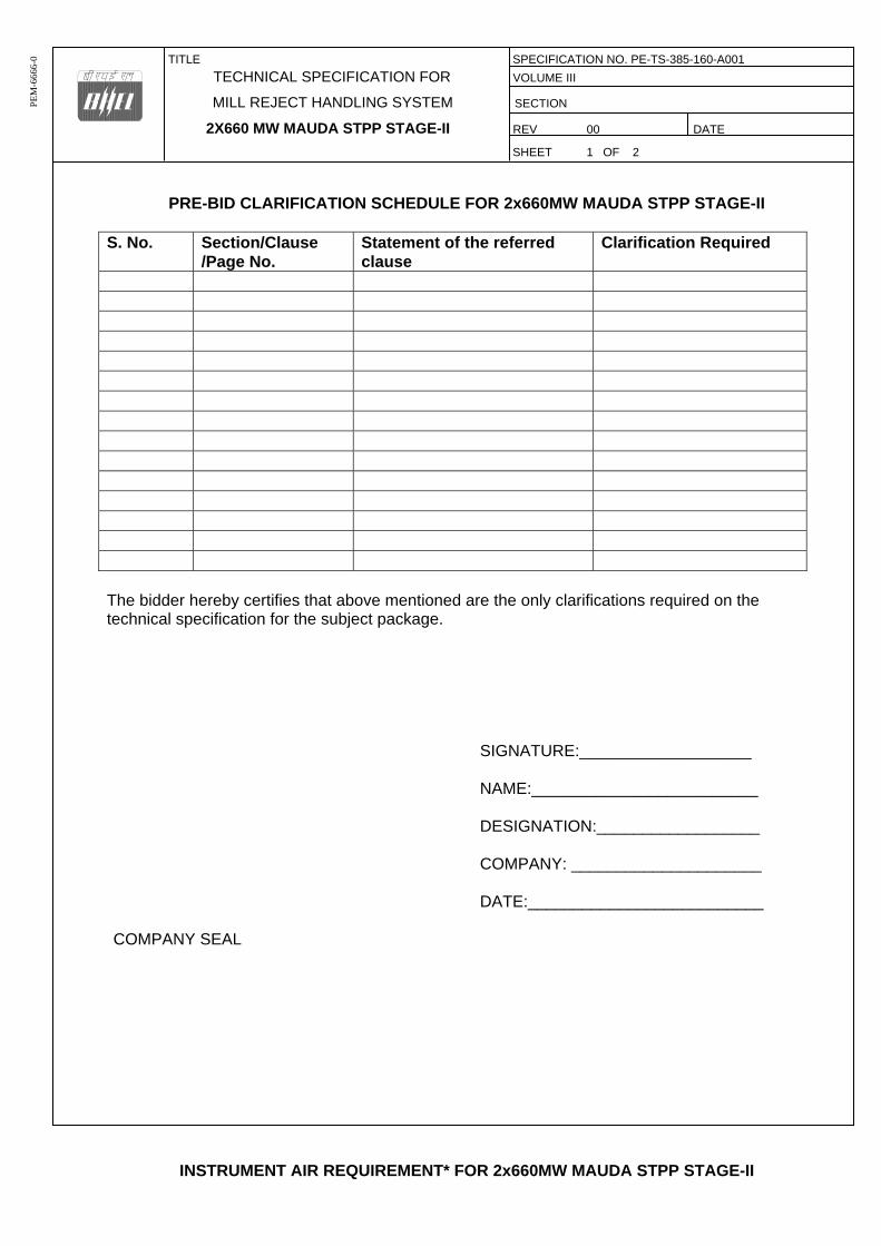
TITLE SPECIFICATION NO. PE-TS-385-160-A001
TECHNICAL SPECIFICATION FOR VOLUME III
MILL REJECT HANDLING SYSTEM SECTION
2X660 MW MAUDA STPP STAGE-II REV 00 DATE SHEET 1 OF 2
PE
M-6
666-
0
PRE-BID CLARIFICATION SCHEDULE FOR 2x660MW MAUDA STPP STAGE-II
S. No. Section/Clause/Page No.
Statement of the referred clause
Clarification Required
The bidder hereby certifies that above mentioned are the only clarifications required on the technical specification for the subject package.
SIGNATURE:___________________ NAME:_________________________ DESIGNATION:__________________ COMPANY: _____________________ DATE:__________________________
COMPANY SEAL
INSTRUMENT AIR REQUIREMENT* FOR 2x660MW MAUDA STPP STAGE-II
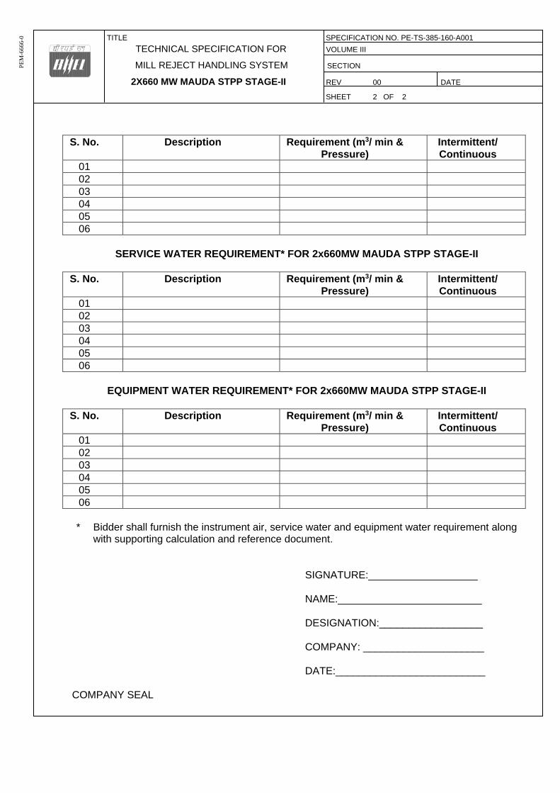
TITLE SPECIFICATION NO. PE-TS-385-160-A001
TECHNICAL SPECIFICATION FOR VOLUME III
MILL REJECT HANDLING SYSTEM SECTION
2X660 MW MAUDA STPP STAGE-II REV 00 DATE SHEET 2 OF 2
PE
M-6
666-
0
S. No. Description Requirement (m3/ min &
Pressure) Intermittent/ Continuous
01 02 03 04 05 06
SERVICE WATER REQUIREMENT* FOR 2x660MW MAUDA STPP STAGE-II
S. No. Description Requirement (m3/ min &
Pressure) Intermittent/ Continuous
01 02 03 04 05 06
EQUIPMENT WATER REQUIREMENT* FOR 2x660MW MAUDA STPP STAGE-II
S. No. Description Requirement (m3/ min &
Pressure) Intermittent/ Continuous
01 02 03 04 05 06
* Bidder shall furnish the instrument air, service water and equipment water requirement along
with supporting calculation and reference document.
SIGNATURE:___________________ NAME:_________________________ DESIGNATION:__________________ COMPANY: _____________________ DATE:__________________________
COMPANY SEAL
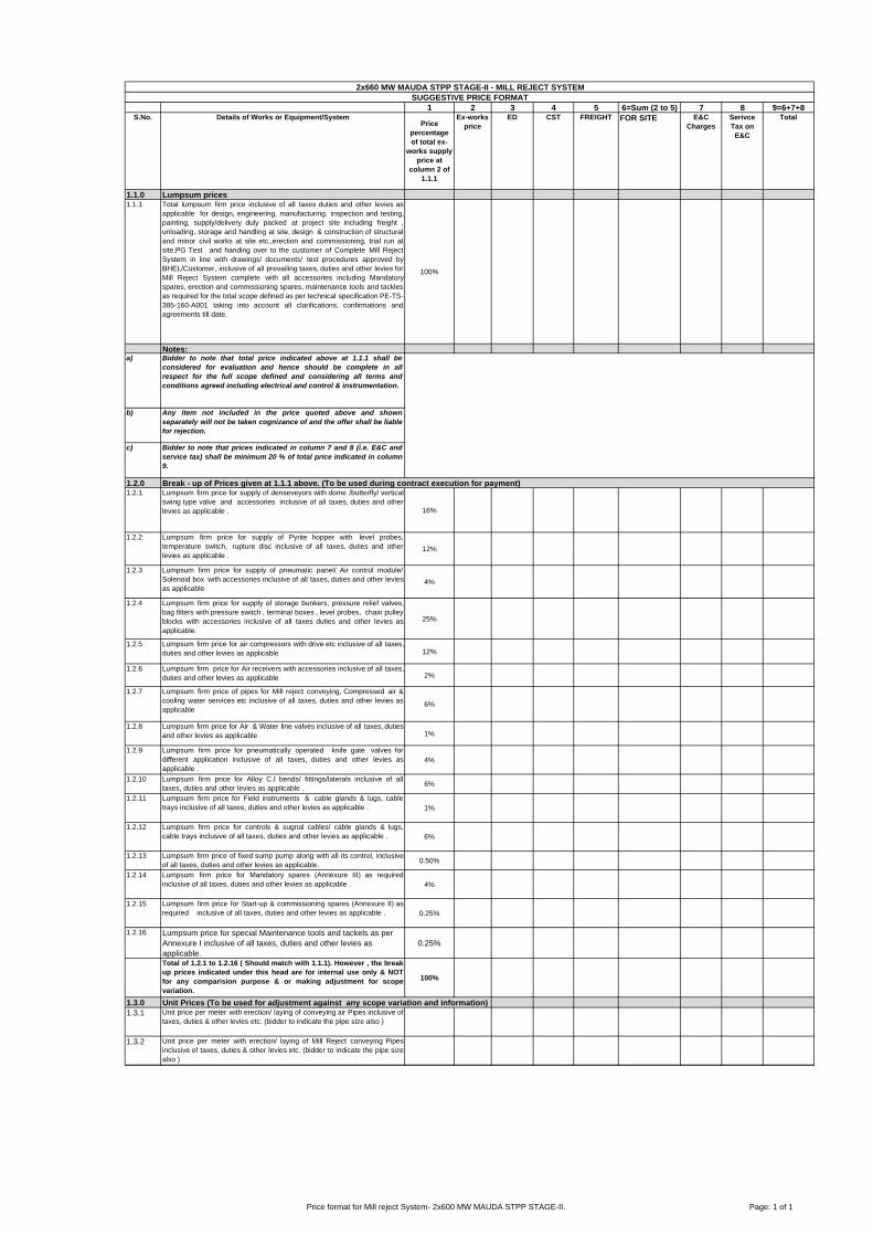
1 2 3 4 5 6=Sum (2 to 5) 7 8 9=6+7+8S.No. Details of Works or Equipment/System
Price percentage of total ex-
works supply price at
column 2 of 1.1.1
Ex-works price
ED CST FREIGHT FOR SITE E&C Charges
Serivce Tax on
E&C
Total
1.1.0 Lumpsum prices1.1.1 Total lumpsum firm price inclusive of all taxes duties and other levies as
applicable for design, engineering, manufacturing, inspection and testing,painting, supply/delivery duly packed at project site including freight ,unloading, storage and handling at site, design & construction of structuraland minor civil works at site etc.,erection and commissioning, trial run atsite,PG Test and handing over to the customer of Complete Mill RejectSystem in line with drawings/ documents/ test procedures approved byBHEL/Customer, inclusive of all prevailing taxes, duties and other levies forMill Reject System complete with all accessories including Mandatoryspares, erection and commissioning spares, maintenance tools and tacklesas required for the total scope defined as per technical specification PE-TS-385-160-A001 taking into account all clarifications, confirmations andagreements till date.
100%
Notes:a) Bidder to note that total price indicated above at 1.1.1 shall be
considered for evaluation and hence should be complete in allrespect for the full scope defined and considering all terms andconditions agreed including electrical and control & instrumentation.
b) Any item not included in the price quoted above and shownseparately will not be taken cognizance of and the offer shall be liablefor rejection.
c) Bidder to note that prices indicated in column 7 and 8 (i.e. E&C andservice tax) shall be minimum 20 % of total price indicated in column9.
1.2.01.2.1 Lumpsum firm price for supply of denseveyors with dome /butterfly/ vertical
swing type valve and accessories inclusive of all taxes, duties and otherlevies as applicable . 16%
1.2.2 Lumpsum firm price for supply of Pyrite hopper with level probes,temperature switch, rupture disc inclusive of all taxes, duties and otherlevies as applicable .
12%
1.2.3 Lumpsum firm price for supply of pneumatic panel/ Air control module/Solenoid box with accessories inclusive of all taxes, duties and other leviesas applicable
4%
1.2.4 Lumpsum firm price for supply of storage bunkers, pressure relief valves,bag filters with pressure switch , terminal boxes , level probes, chain pulleyblocks with accessories inclusive of all taxes duties and other levies asapplicable.
25%
1.2.5 Lumpsum firm price for air compressors with drive etc inclusive of all taxes,duties and other levies as applicable 12%
1.2.6 Lumpsum firm price for Air receivers with accessories inclusive of all taxes,duties and other levies as applicable 2%
1.2.7 Lumpsum firm price of pipes for Mill reject conveying, Compressed air &cooling water services etc inclusive of all taxes, duties and other levies asapplicable
6%
1.2.8 Lumpsum firm price for Air & Water line valves inclusive of all taxes, dutiesand other levies as applicable 1%
1.2.9 Lumpsum firm price for pneumatically operated knife gate valves fordifferent application inclusive of all taxes, duties and other levies asapplicable .
4%
1.2.10 Lumpsum firm price for Alloy C.I bends/ fittings/laterals inclusive of alltaxes, duties and other levies as applicable .
6%
1.2.11 Lumpsum firm price for Field instruments & cable glands & lugs, cabletrays inclusive of all taxes, duties and other levies as applicable . 1%
1.2.12 Lumpsum firm price for controls & sugnal cables/ cable glands & lugs,cable trays inclusive of all taxes, duties and other levies as applicable . 6%
1.2.13 Lumpsum firm price of fixed sump pump along with all its control, inclusiveof all taxes, duties and other levies as applicable.
0.50%
1.2.14 Lumpsum firm price for Mandatory spares (Annexure III) as requiredinclusive of all taxes, duties and other levies as applicable . 4%
1.2.15 Lumpsum firm price for Start-up & commissioning spares (Annexure II) asrequired inclusive of all taxes, duties and other levies as applicable . 0.25%
1.2.16 Lumpsum price for special Maintenance tools and tackels as per Annexure I inclusive of all taxes, duties and other levies as applicable.
0.25%
Total of 1.2.1 to 1.2.16 ( Should match with 1.1.1). However , the breakup prices indicated under this head are for internal use only & NOTfor any comparision purpose & or making adjustment for scopevariation.
100%
1.3.0 Unit Prices (To be used for adjustment against any scope variation and information) 1.3.1 Unit price per meter with erection/ laying of conveying air Pipes inclusive of
taxes, duties & other levies etc. (bidder to indicate the pipe size also )
1.3.2 Unit price per meter with erection/ laying of Mill Reject conveying Pipesinclusive of taxes, duties & other levies etc. (bidder to indicate the pipe sizealso )
2x660 MW MAUDA STPP STAGE-II - MILL REJECT SYSTEMSUGGESTIVE PRICE FORMAT
Break - up of Prices given at 1.1.1 above. (To be used during contract execution for payment)
Price format for Mill reject System- 2x600 MW MAUDA STPP STAGE-II. Page: 1 of 1

Sl.No. Description Qty. Unit Unit Ex-works price
Total ex-works price
ED CST FREIGHT FOR SITE
ANNEXURE-I2x660 MW MAUDA STPP STAGE-II - MILL REJECT SYSTEM
List of Special Maintenance Tools & Tackles
Price schedule for 2x660 MW MAUDA STPP STAGE-II. Mill Reject System- List of Maintenance ToolsPage : 2 of 5
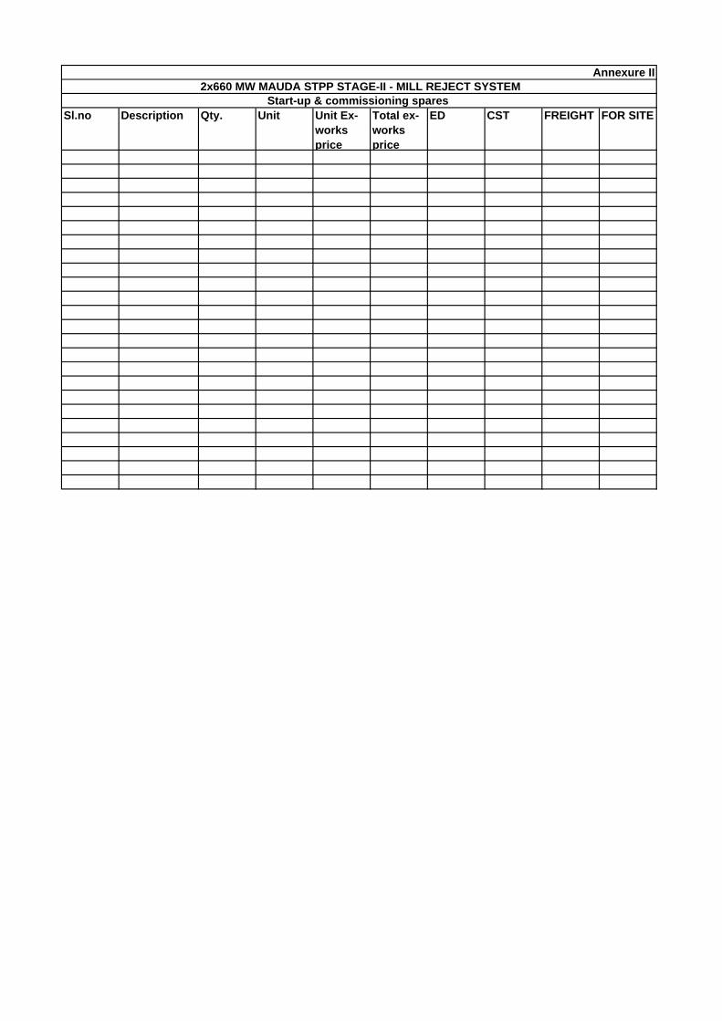
Sl.no Description Qty. Unit Unit Ex-works price
Total ex-works price
ED CST FREIGHT FOR SITE
2x660 MW MAUDA STPP STAGE-II - MILL REJECT SYSTEMStart-up & commissioning spares
Annexure II

Sl.no Description Qty. Unit Unit Ex-works price Total ex-works price
ED CST FREIGHT FOR SITE
1 Mill Reject Handling System
A. Pneumatic Conveying System1. Conveying System Sparesa) Pneumatic main valves 4 sets of each typeb) Pneumatic/Solenoid Two/ Three position control valve
4 sets of each type
c) Plate/Dome valve (including seals) with Actuators (pneumatic/hydraulic)
6 nos.
d) Plate/Dome valve seals 6 setsB. Compressors (Reciprocating type, ifapplicable)1. Compressor with motor 1 no of each
2 MEASURING INSTRUMENTS
1. Electronic Transmitters1.1 Transmitters of all types, ranges andmodel no. (for the measurement ofPressure,differential pressure flow, level,etc.)
10% or 1 no. of each type and modelwhichever is more
1.2 Level Transmitters (Ultrasonic/ radartype)
50% of each type and length,including sensors
2. Temperature elements2.1 RTD’s* of each type and length(withhead assembly, terminal block & nipple)
10% or 2 nos. of each type and length,whichever is more
2.2 Thermocouples of each type like Ktype,R-type, metal etc. * (with headassembly, terminal block & nipple)
10% or 2 nos. of each type and lengthwhich ever is more
2.3 Cold Junction compensation boxes ofeach model (if applicable)
10% or 2 nos. which ever is more- NotApplicable
2.4 Themostatic units for each model ofCJC box (if applicable)
10% or 2 nos. which ever is more- NotApplicable
2.5 Thermowell for application like milloutlet temperature and SH/RH/Eco/ fluegas temp. in furnace
10% or 2 nos. of each type and lengthwhichever is more
2.6 Temperature transmitters 10% of each type and length3. Local Indicators like temperaturegauges, pressure gauges, differentialpressure gauges, flow gauges, flow metersetc.,
5% or 1 no. of each make, model andtype whichever is more (to be divided to various ranges in proportion to main of all make, model, type population)
4. Process Actuated Switch DevicesIncludes all types of Pressure, differentialpressure, flow, temperature, differentialtemperature, level switch Devices
5% or 1 no. of each type and modelwhichever is more
5. PD Type Flow Transmitters 1 no. of each type and model6. Flue gas Analyzer instruments foroxygen(i) Electronic card Assemblies of each type(ii) Sets of gaskets/"O” rings(iii) Temperature Sensor & heater assembly(iv) Complete Probe with shield assembly(v) Consumables like filter elements etc
1 no. Each complete instrument10%2 sets20%2 nos100%
3
PROCESS CONNECTION PIPING (FORIMPULSE PIPING/TUBING, SAMPLINGPIPING / TUBING AND AIR SUPPLYPIPING AS APPLICABLE)
1. Valves of all types and models 10% or 1 no. of each type, class, size and model whichever is more.
2. 2 way, 3way, 5way valve manifolds 10% or 1 no. of each type, class, size andmodel whichever is more.
3. Fittings 10% or 1 packet of each type, class,size and model whichever is more.
4. Purge meters 5% of each model or 1 no.whichever is more.
5. Filter regulators 20% of each model or 2 nos.whichever is more.
4INSTRUMENTATION CABLE, INTERNAL WIRING & ELECTRICAL FIELD
1. Pre fabricated cable of each type. 10% of installed quantity
2. Pre fabricated cable connector of each type
10% or 1 no. of each type and model, whichever is more.
3. Other cables 5% of each type, pair and size of actual installed quantity
5CONTROL VALVES, ACTUATORS &ACCESSORIES1. Pneumatic and electro-hydraulicactuator assembly
10% or 1 no. of each type, model and rating, whichever is more
2. Valve trim (including cage, plug, stem,seat rings, guide bushings etc.)
1 set for each type of control valve, whichever is more
3. Diaphragms, O’ rings, seals etc. of alltypes, make etc.
200%
4. Pressure Gauges of all types, make, rating etc.
10% or 2 nos. of each type whichever is more.
5. Solenoid valves (if applicable) 10% or 2 nos. of each type whichever is more.
6.Positioner units 10% or 2 nos. of each type whichever is more.
a)
b)
c)
d)
e)
In case spares indicated in the list are not applcable to the particular design offered by the bidder, the bidder should offer spares applicable to the offered design with quantities genaerally in line with the approach followed in the above list.
Wherever bidder has indicated an item as not applicable, the same will have to be supplied free of cost, in case it is found applicable during detail engineering.
NOTES:
2x660 MW MAUDA STPP STAGE-II - MILL REJECT SYSTEMList of Mandatory Spares
Annexure III
Unless stated otherwise, a ‘set’ means item or sub-items required for each type/ size, range of assembly/ sub- assembly required for complete replacement in one equipment system; it is further intended that the assembly/ sub-assembly which have different orientation (like left hand or right hand, top or bottom), different direction of rotation or mirror image positioning or any other reasons which result in marinating two different sets of spares to be used for subject assembly/ sub assembly, these shall be considered as different type of assembly/ sub assembly.
Wherever quantity has been specified as percentage(%), the quantity of mandatory spares to be provided by the vendor shall be the specified percentage (%) of total population required to meet the specification requirements. In case the quantity of mandatory spares so calculated happens to be in fraction, the same shall be rounded off to next higher whole number.
Wherever the quantities have been indicated for each type, size, thickness, material, radius, range etc, these shall cover all the items supplied and installed and the breakup of these shall be furnished by the vendor during detail engineering.
Price schedule for 2x600 MW MAUDA STPP STAGE-II (Mandatory Spares)

SL NO VOULME/ SECTION
PAGE NO.
CLAUSE NO.
TECHNICAL SPECIFICATIO
N/ TENDER DOCUMENT
COMPLETE DESCRIPTION OF DEVIATION
COST OF WITHDRAWL OF
DEVIATION
REFERENCE OF PRICE
SCHEDULE ON WHICH COST OF WITHDRAWL OF
DEVIATION IS APPLICABLE
NATURE OF COST OF
WITHDRAWL OF DEVIATION (POSITIVE/ NEGATIVE)
14. In case of descrepancy in the nature of impact (positive/ negative), positive will be considered for evaluation and negative for ordering.
8. Bidders to note that any deviation (technical/commercial) not listed in above and asked after Part-I opening shall not be considered.9. For deviations w.r.t. Payment terms, Liquidated damages, Firm prices and submission of E1/ E2 forms before claiming 10% payment, if a bidder chooses not to give any cost of withdrawl of deviation loading as per Annexure-VIII of GCC, Rev-06 will apply. For any other deviation mentioned in un-priced copy of this format submitted with Part-I bid but not mentioned in priced copy of 10. Any deviation mentioned in priced copy of this format, but not mentioned in the un-priced copy, shall not be accepted.
11. All techno-commercial terms and conditions of NIT shall be deemed to have been accepted by the bidder, other than those listed in unpriced copy of this format.
12. Cost of withdrawl is to be given seperately for each deviation. In no event bidder should club cost of withdrawl of more than one deviation else cost of withdrawl of such deviations which have been clubbed together shall be considered as NIL.
13. In case nature of cost of withdrawl (positive/negative) is not specified it shall be assumed as positive.
2. For directly dispatchable items, cost of withdrawl of deviation will be applicable on the basic price including taxes, duties & freight. 3. All the bidders have to list out all their Technical & Commercial Deviations (if any) in detail in the above format.4. Any deviation not mentioned above and shown separately or found hidden in offer, will not be taken cognizance of.5. Bidder shall submit duly filled unpriced copy of above format indicating "quoted" in "cost of withdrawl of deviation" column of the schedule above along with their Techno-commercial offer, wherever applicable.6. Bidder shall furnish price copy of above format along with price bid.7. The final decision of acceptance/ rejection of the deviations quoted by the bidder shall be at discretion of the Purchaser.
NAME DESIGNATIONS SIGN & DATE
NOTES:1. For self manufactured items of bidder, cost of withdrawl of deviation will be applicable on the basic price (i.e. excluding taxes, duties & freight) only.
PARTICULARS OF BIDDERS/ AUTHORISED REPRESENTATIVE
COMMERCIAL DEVIATIONS
TECHNICAL DEVIATIONS
ANNEXURE-IV: DEVIATION SHEET (COST OF WITHDRAWAL)PROJECT:- 2x660 MW MAUDA STPP STAGE-IIPACKAGE:- MILL REJECT HANDLING SYSTEM
TENDER ENQUIRY REFERENCE:-NAME OF VENDOR:-
REASON FOR QUOTING DEVIATION

Sl.No. Description / Item Working Standby Power Consumption (KW) (at motor input
terminal)
Duty Factor Total Power Consumption (KW)
1 2 3 4 5 6 7 = 3 x 5 x 61 Conveying Air Compressor 1 1 1.00
Total KWNotes
1
2
3
4 Base aux power figure is 151.5 KW at duty factor 1.00.
ANNEXURE -IV
For bid evaluation purpose on account of guaranteed auxiliary power consumption over base auxilliary power figure mentioned below, the same shall be loaded at the rate of 3299 USD per KW for the differential power consumption.
2 x 660 MW MAUDA STPP STAGE-II - Mill Reject Handling System Mode: Pneumatic Conveying
If the actual power consumption exceeds the guaranteed power consumption, liquidated damages shall be payable by the Contractor at the rate of 3299 USD per KW excess power consumption, over the base guaranteed figure indicated by him in his bid. Such liquidated damages may be recovered by the Owner by deduction from the contract price or by enforcing the contract performance guarantee or in any other manner deemed fit by the Owner. For this purpose, the drives of standby equipment shall not be considered.
Power consumption (KW) of air compressors shall be measured at motor input terminals when operating at the rated capacity and pressure and performed on test rig at the vendor's works and actual motor shall be used for this purpose.

TITLE SPECIFICATION NO. PE-TS-385-160-A001
TECHNICAL SPECIFICATION FOR VOLUME III
MILL REJECT HANDLING SYSTEM SECTION
2X660MW MAUDA STPP STAGE-II REV 0 DATE 20-06-2014
SHEET OF 3 1
PE
M-6
666-
0
ANNEXURE-VI
DRAWINGS/ DOCUMENTS TO BE SUBMITTED AFTER AWARD OF CONTRACT
The successful bidder shall submit the following drawings / documents during detail engineering for
customer’s approval /information:
Sl. No.
BHEL DRG.NO DRAWING TITLE REMARKS SUBMISSION
SCHEDULE - WEEK NUMBER
FROM DATE OF
LOI
1 PE-V0-385-160-A001 P & I Diagram- Mill Reject Handling System APPROVAL 10 2 PE-V0-385-160-A002 P & I Diagram of Compressor APPROVAL 10 3
PE-V0-385-160-A003
Design Philosophy of MRS and System Sizing Calculation (Compressor, Air receiver, blow tank, pyrite hopper, bag filter, bunker)
APPROVAL
10 4
PE-V0-385-160-A004
Equipment Layout Drawing of Unit Assembly & Piping Layout Details of Mill Reject System /Trench & Insert details of MRS/ Pipe Support Drawing/ piping layout between compressor house to mill bay area
APPROVAL
4 5
PE-V0-385-160-A005 Layout - Compressor House
APPROVAL
10 6 PE-V0-385-160-A006 Earthing & Cable Tray Layout for MRS APPROVAL 10 7 PE-V0-385-160-A007 Load Data for Bunker APPROVAL 10 8 PE-V0-385-160-A008 G-A- of Self manufactured Items INFORMATION 10 9 PE-V0-385-160-A009 GA and foundation details of Air Receiver INFORMATION 6
10 PE-V0-385-160-A010 GA of Bunker APPROVAL 6 11 PE-V0-385-160-A011 GA and Data sheet of Rupture Disc INFORMATION 6 12 PE-V0-385-160-A012 GA and Data sheet of Metallic Expansion Bellow INFORMATION 8 13 PE-V0-385-160-A013 GA and Data sheet of Chain Pulley Block INFORMATION 8 14
PE-V0-385-160-A014 GA, Data sheet & Performance Curve of Conveying Air Compressor Motor
APPROVAL 8
15 PE-V0-385-160-A015
GA, Data sheet & foundation detail of Compressor and wiring diagram of compressor panel
APPROVAL 10
16 PE-V0-385-160-A016 GA and Data sheet of Bag Filter INFORMATION 10 17
PE-V0-385-160-A017 GA and Data Sheet of Sump Pump (fixed/portable type) & Motor Data sheet for Drain sump Pump & wiring diagram for sump pump
INFORMATION8
18 PE-V0-385-160-A018
GA and Data sheet of Manual/Pneumatic Operated Knife Gate & Pneumatic cylinder
APPROVAL 10
19 PE-V0-385-160-A019
GA of Gate Valve/ NRV/ Check Valve/Globe Valve/Ball Valve/Butterfly Valve
INFORMATION8
20 PE-V0-385-160-A020 Data sheet of Instruments - MRS APPROVAL 12 21 PE-V0-385-160-A021 Cable Schedule - Signal and Control INFORMATION 12 22
PE-V0-385-160-A022 Control Write Up & Interlocks, Pneumatic Circuit of Transporter Vessel, Block Logic for MRS & I/O List & HMI-Screens for MRS
APPROVAL 12
23 PE-V0-385-160-A023 Cable interconnection diagram APPROVAL 10 24 PE-V0-385-160-A024 GA of Local Control Panels APPROVAL 14 25 PE-V0-385-160-A025 QAP of Self manufactured Items APPROVAL 10 26 PE-V0-385-160-A026 QAP for Local Control Panels APPROVAL 8 27 PE-V0-385-160-A027 QAP for Bag Filter APPROVAL 10 28 PE-V0-385-160-A028 QAP for Conveying Air Compressor APPROVAL 8
TITLE SPECIFICATION NO. PE-TS-385-160-A001
TECHNICAL SPECIFICATION FOR VOLUME III
MILL REJECT HANDLING SYSTEM SECTION
2X660MW MAUDA STPP STAGE-II REV 0 DATE 20-06-2014
SHEET OF 3 2
PE
M-6
666-
0
29 PE-V0-385-160-A029 QAP for Conveying air compressor Motors APPROVAL 10 30
PE-V0-385-160-A030 QAP for Knife Gate Valve (HW/CW/Pneumatic) & pneumatic cylinder
APPROVAL 10
31 PE-V0-385-160-A031 QAP for Chain Pulley Block APPROVAL 8 32 PE-V0-385-160-A032 QAP for Ball Valve/Butterfly valve APPROVAL 8 33 PE-V0-385-160-A033 QAP for Sump Pump with Motor APPROVAL 12 34 PE-V0-385-160-A034 QAP for Metallic Expansion Bellows APPROVAL 10 35 PE-V0-385-160-A035 QAP for MS ERW Pipes APPROVAL 8 36 PE-V0-385-160-A036 QAP for Bunker & Misc MS Structurals / Plates APPROVAL 6 37 PE-V0-385-160-A037 QAP for Rupture Disc APPROVAL 6 38 PE-V0-385-160-A038 QAP for GM Gate/Globe/Check Valve/Ball valve APPROVAL 8 39 PE-V0-385-160-A039 QAP of INSTRUMENTS (PG/PS/PT/TS/TG/SV) APPROVAL 12 40 PE-V0-385-160-A040 Type test certificate/procedure for MRS compressor motor APPROVAL 12 41 PE-V0-385-160-A041 Piping and Valve Schedule INFORMATION 10 42 PE-V0-385-160-A042 Painting Schedule INFORMATION 10 43 PE-V0-385-160-A043 Instrument Schedule INFORMATION 10 44 PE-V0-385-160-A044 Sub Vendor List with Inspection Category APPROVAL 10 45 PE-V0-385-160-A045 Welding Procedure Specification APPROVAL 4 46 PE-V0-385-160-A046 O&M Manual INFORMATION 8 47 PE-V0-385-160-A047 PG test Proceedure APPROVAL 24
Notes:
1. The above drawing list is tentative and shall be finalized with the successful bidder after placement of order. While some of the drawings indicated above may not be applicable, some additional drawings may also be required based on scope of work.
2. Drawings shall be prepared in Auto-Cad latest edition. Required no. of hard and soft copies (editable) of the drawings shall be furnished as per requirement specified elsewhere in the specification.
3. Only manual calculation with authentic supporting literature (e.g. extracts of hand Book/ standard/codes) shall be acceptable. All design calculations and drawings shall be in SI system only.
4. Bidder to note that all values/dimensions/elevations etc. without supporting back up data adopted/assumed by the successful bidder (during contract stage) in the design calculation/drawings shall be taken by the customer/owner to be correct unless they are stipulated in the specification. Any problem arising later in this regard shall be made good by the successful bidder at his cost and no extension of time shall be granted for the same.
5. All the drawings and documents including general arrangement drawing, data sheet, calculation etc. to be furnished to the customer during detailed engineering stage shall include / indicate the following details for clarity w.r.t. Inspection, construction, erection and maintenance etc.:-
a) All drawings and documents shall indicate the list of all reference drawings including general arrangement.
b) All drawings shall include / show plan, elevation, side view, cross - section, skin section, blow - up view; all major self-manufactured and bought out items shall be labelled and included in BOQ / BOM in tabular form.
c) Painting schedule shall also be made as a part of general arrangement drawing of each equipment / items indicating at least 3 trade name.
d) All the drawings required to be furnished to customer during detailed engineering stage shall include technical parameters, details of paints and lubrication, hardness and BOQ / BOM in tabular form indicating all major components including bought out
TITLE SPECIFICATION NO. PE-TS-385-160-A001
TECHNICAL SPECIFICATION FOR VOLUME III
MILL REJECT HANDLING SYSTEM SECTION
2X660MW MAUDA STPP STAGE-II REV 0 DATE 20-06-2014
SHEET OF 3 3
PE
M-6
666-
0
items and their quantity, material of construction indicating its applicable code / standard, weight, make etc.
e) Drawings/ documents to be submitted for purchasers review/ approval shall be under Revision A, B, C… etc. while drawings /documents to be submitted thereafter for customer’s approval after purchaser’s approval shall be under R-0, 1, 2, 3 ….etc.
6. Drawings and documents not covered above but required to check safety of machines/system, shall be submitted during detailed engineering stage without any commercial implication.
7. All drawings shall include "B.O.M" and indicate quantity, material of construction, make along with IS/BS No., Technical parameters, dimensions, hardness, machining symbol and tolerance, requirement of radiography and hydraulic tests, painting details, elevation, side view, plan, skin section and blow-up view for clarity.
8. All drawings shall be prepared as per BHEL's title block and bear BHEL's drawing No. 9. Schedule of drawings submissions, comment incorporations & approval shall be as stipulated
in the specifications. The successful bidder shall depute his design personnel to BHEL’s/ Customer’s/ Consultant’s office for across the table resolution of issues and to get documents approved in the stipulated time.
10. Bidder to follow the following the drawing submission schedule: 1st submission of drawings from date of LOI as per the submission schedule. Every revised submission incorporating comments – within 10 days. BHEL/Customer shall furnish their approval/comments within 21 days of submission Bidder to submit revised drawings complete in all respects incorporating all
comments. Any incomplete drawing submitted shall be treated as non-submission with delays attributable to bidder’s account. For any clarification/ discussion required to complete the drawings, the bidder shall himself depute his personal to BHEL for across the table discussions/ finalizations/ submissions of drawings.

TITLE SPECIFICATION NO. PE-TS-385-160-A001
TECHNICAL SPECIFICATION FOR VOLUME III
MILL REJECT HANDLING SYSTEM SECTION
2X660MW MAUDA STPP STAGE-II REV 0 DATE 20-06-2014
SHEET OF 1 1
PE
M-6
666-
0
LIST OF BASIC DRAWINGS
BHEL DRG NO DRG TITLE
PE-V0-391-160-A001 P & I Diagram- Mill Reject Handling System
PE-V0-391-160-A003 Design Philosophy of MRS and System Sizing Calculation (Compressor, Air receiver, blow tank, pyrite hopper, bag filter, bunker)
PE-V0-391-160-A004
Equipment Layout Drawing of Unit Assembly & Piping Layout Details of Mill Reject System /Trench & Insert details of MRS/ Pipe Support Drawing/ piping layout between compressor house to mill bay area
PE-V0-391-160-A005 Layout - Compressor House
PE-V0-391-160-A007 Load Data for Bunker
PE-V0-391-160-A008 G-A- of Self manufactured Items
PE-V0-391-160-A009 GA and foundation details of Air Receiver
PE-V0-391-160-A010 GA of Bunker
PE-V0-391-160-A014 GA, Data sheet & Performance Curve of Conveying Air Compressor Motor
PE-V0-391-160-A015 GA, Data sheet & foundation detail of Compressor and wiring diagram of compressor panel
PE-V0-391-160-A022 Control Write Up & Interlocks, Pneumatic Circuit of Transporter Vessel, Block Logic for MRS & I/O List & HMI-Screens for MRS
PE-V0-385-160-A023 Cable interconnection diagram
PE-V0-391-160-A044 Sub Vendor List with Inspection Category
Note: Drawings listed above have been identified as basic drawings. During contract engineering stage, approval of these drawings from BHEL/Customer shall be treated as clearance to milestone payment for completion of design & engineering.
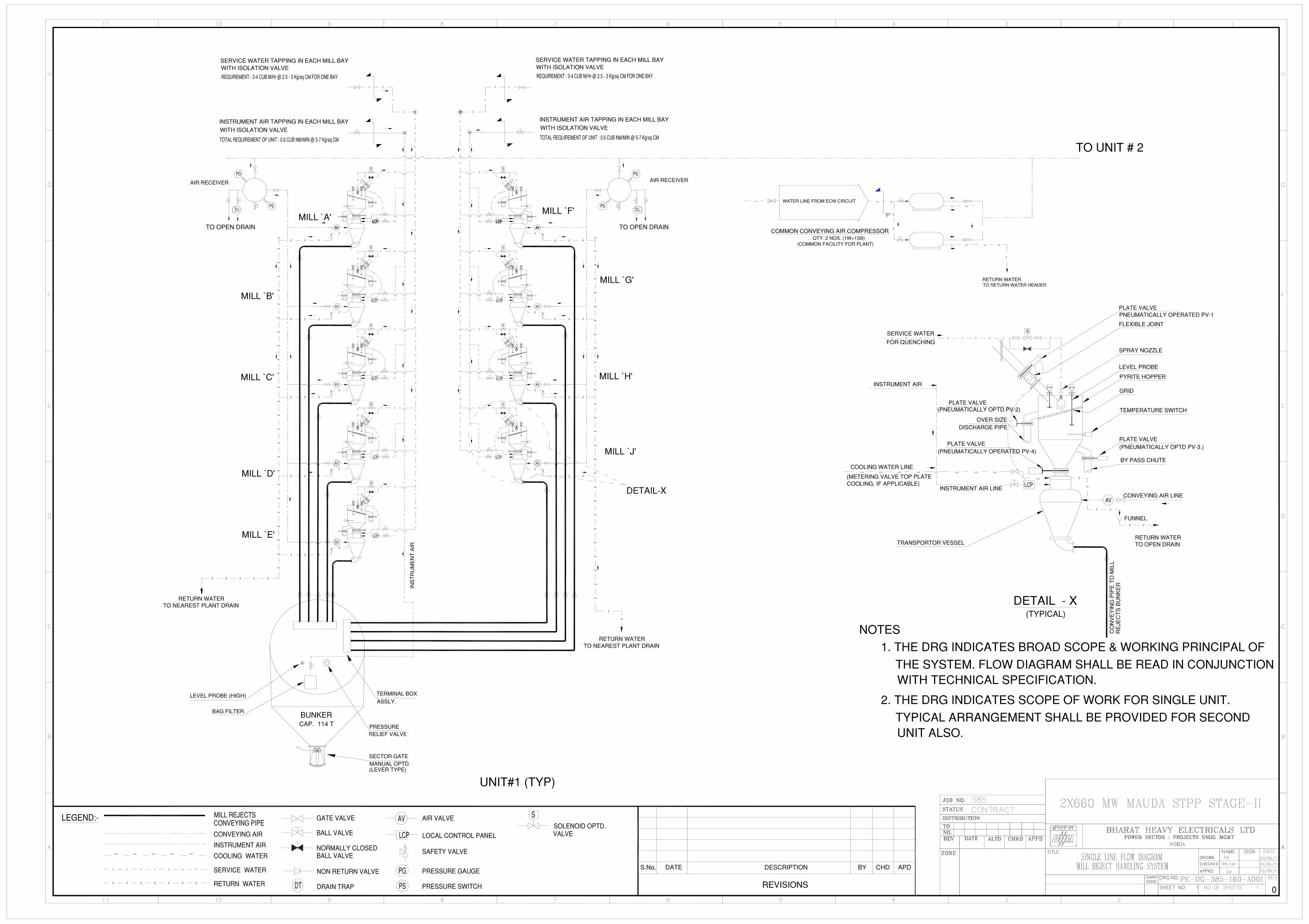

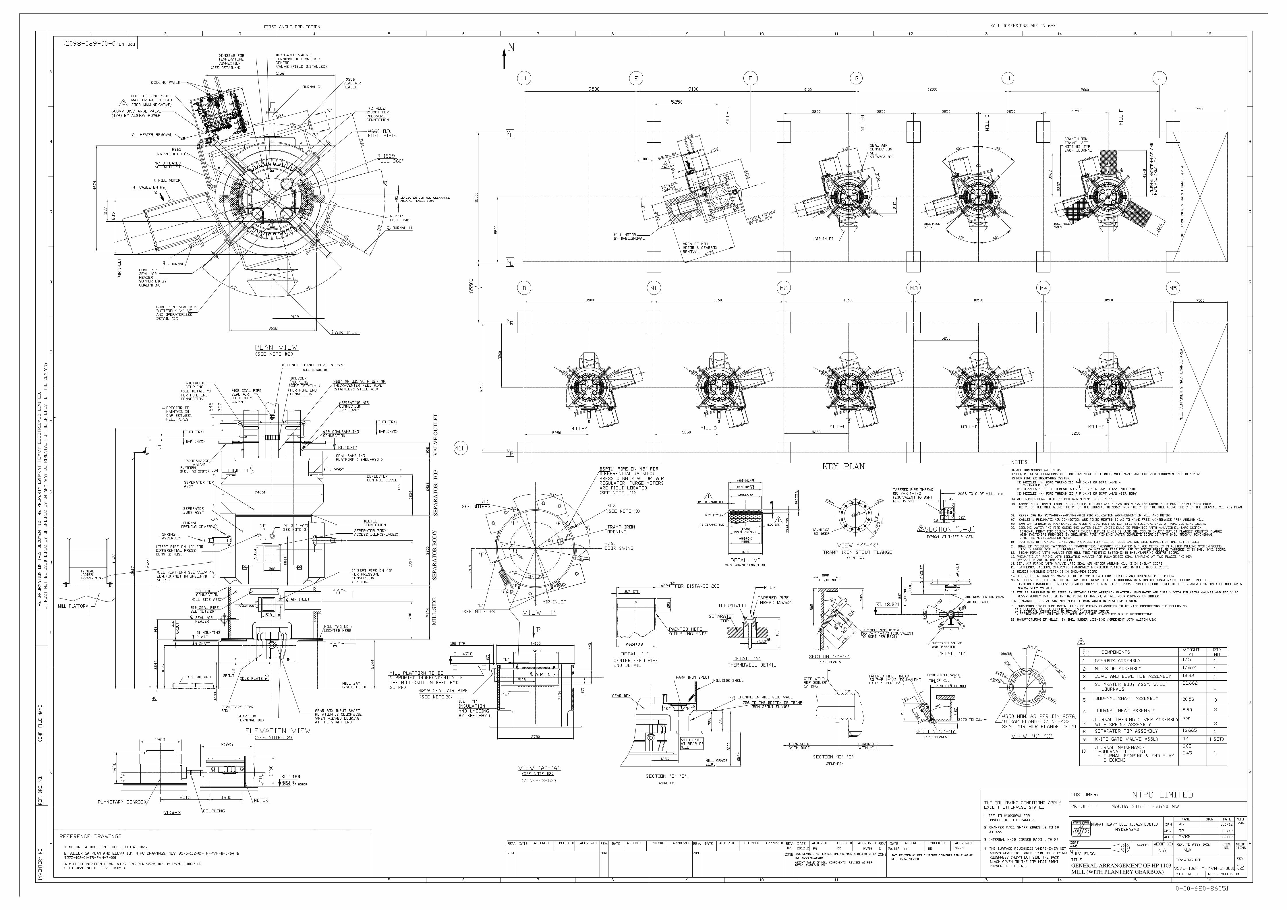
ɸ