Classifying and Understanding Thermal Interface … I/I-3 -.pdfClassifying and Understanding Thermal...
51
© Copyright 2012 DS&A LLC Classifying and Understanding Thermal Interface Materials for Power LED Applications David L. Saums, Principal DS&A LLC Amesbury MA USA www.dsa-thermal.com IMAPS France 7 th European Advanced Technology Workshop on Thermal Management and Micropackaging La Rochelle, France 1-2 February 2012
-
Upload
hoangquynh -
Category
Documents
-
view
238 -
download
3
Transcript of Classifying and Understanding Thermal Interface … I/I-3 -.pdfClassifying and Understanding Thermal...

© Copyright 2012 DS&A LLC
Classifying and Understanding Thermal Interface Materials
for Power LED Applications
David L. Saums, Principal DS&A LLC
Amesbury MA USA www.dsa-thermal.com
IMAPS France 7th European Advanced Technology Workshop on Thermal Management and Micropackaging
La Rochelle, France 1-2 February 2012
Classifying and Understanding Thermal Interface Materials for Power LED Applications
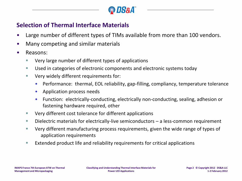
Selection of Thermal Interface Materials
• Large number of different types of TIMs available from more than 100 vendors.
• Many competing and similar materials
• Reasons:
Very large number of different types of applications
Used in categories of electronic components and electronic systems today
Very widely different requirements for:
• Performance: thermal, EOL reliability, gap-filling, compliancy, temperature tolerance
• Application process needs
• Function: electrically-conducting, electrically non-conducting, sealing, adhesion or fastening hardware required, other
Very different cost tolerance for different applications
Dielectric materials for electrically-live semiconductors – a less-common requirement
Very different manufacturing process requirements, given the wide range of types of application requirements
Extended product life and reliability requirements for critical applications
IMAPS France 7th European ATW on Thermal Management and Micropackaging
Page 2 © Copyright 2012 DS&A LLC 1-2 February 2012

Classifying and Understanding Thermal Interface Materials for Power LED Applications
Selection of Thermal Interface Materials
• Maximum performance is not the solitary method of selection for the “best” TIM.
• Performance by what measure?
The answer to this question is driven by the application requirements.
Choices: thermal, electrical, dielectric, gap-filling, dispensable, EOL reliability, more…
• What are the primary drivers for TIM material thermal performance as a very generalized statement?
1. Clamping force applied: How much force is applied to a compliant form of TIM, to achieve the thinnest possible layer and maximum metal-to-metal contact.
2. Surface wetting: To what degree does the TIM wet to the surfaces, to maximize heat transfer capability and eliminate all air pockets?
3. Bulk thermal conductivity
• As a general statement, thermal conductivity is one of three primary drivers for performance for TIM materials.
Note that for some classes of TIM materials, the bulk thermal conductivity value can be quite low, including for many thermal pastes and similar compounds, as other properties are more important.
For any one material type
IMAPS France 7th European ATW on Thermal Management and Micropackaging
Page 3 © Copyright 2012 DS&A LLC 1-2 February 2012
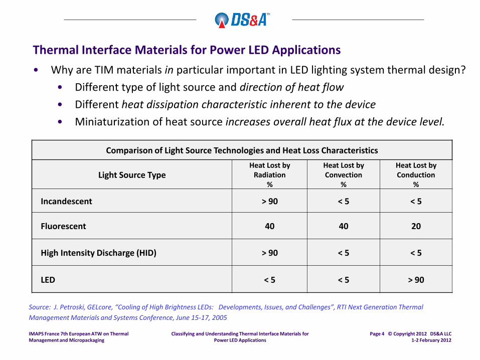
• Why are TIM materials in particular important in LED lighting system thermal design?
• Different type of light source and direction of heat flow
• Different heat dissipation characteristic inherent to the device
• Miniaturization of heat source increases overall heat flux at the device level.
Classifying and Understanding Thermal Interface Materials for Power LED Applications
Thermal Interface Materials for Power LED Applications
IMAPS France 7th European ATW on Thermal Management and Micropackaging
Page 4 © Copyright 2012 DS&A LLC 1-2 February 2012
Comparison of Light Source Technologies and Heat Loss Characteristics
Light Source Type Heat Lost by
Radiation %
Heat Lost by Convection
%
Heat Lost by Conduction
%
Incandescent > 90 < 5 < 5
Fluorescent 40 40 20
High Intensity Discharge (HID) > 90 < 5 < 5
LED < 5 < 5 > 90
Source: J. Petroski, GELcore, “Cooling of High Brightness LEDs: Developments, Issues, and Challenges”, RTI Next Generation Thermal
Management Materials and Systems Conference, June 15-17, 2005

Classifying and Understanding Thermal Interface Materials for Power LED Applications
Thermal Interface Materials for Power LED Applications
IMAPS France 7th European ATW on Thermal Management and Micropackaging
Page 5 © Copyright 2012 DS&A LLC 1-2 February 2012
DS&A LLC
Thermal Interface Material General Outline for LED Array Applications © 2012 DS&A LLC
General Application Type Typical TIM Materials Used Typical
Thickness Ranges
Attachment of LED array substrate to “heat sink slug” Solders,
NanoFoil® 0.05 - 0.10 mm
(0.002" - 0.004")
Attachment of “heat sink slug” to finned heat sink Thermal Pastes,
Non-Silicone Thermal Pastes, Non-Silicone Dry Thermal Paste Preforms
0.0125 – 0.125 mm (0.0005" - 0.005")
Heat Sink to luminaire housing interior surface Gap-Fillers 0.25 – 3.80 mm (0.010" - 0.150")
Heat Sink to heat pipe, other applications Thermally-Conductive Adhesives,
Thermally-Conductive Cure-in-Place Compounds 0.075- 0.63 mm (0.003" - 0.025")
Note: These are intended to be statements of typical usages by material type for these generalized application areas.

Materials that provide a thermal function are highlighted in red
Thermal Interface Materials for Power LED Applications
• Packaging, electrical contacts, and thermal materials for a typical LED:
IMAPS France 7th European ATW on Thermal Management and Micropackaging
Page 6 © Copyright 2012 DS&A LLC 1-2 February 2012
Classifying and Understanding Thermal Interface Materials for Power LED Applications
Thermal Interface Material
(TIM2)
Drawing: Philips Lumileds, with comments added.
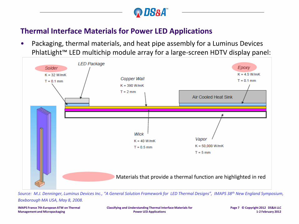
• Packaging, thermal materials, and heat pipe assembly for a Luminus Devices PhlatLight™ LED multichip module array for a large-screen HDTV display panel:
Classifying and Understanding Thermal Interface Materials for Power LED Applications
Thermal Interface Materials for Power LED Applications
IMAPS France 7th European ATW on Thermal Management and Micropackaging
Page 7 © Copyright 2012 DS&A LLC 1-2 February 2012
Materials that provide a thermal function are highlighted in red
Source: M.J. Denninger, Luminus Devices Inc., “A General Solution Framework for LED Thermal Designs”, IMAPS 38th New England Symposium,
Boxborough MA USA, May 8, 2008.

Classifying and Understanding Thermal Interface Materials for Power LED Applications
Thermal Interface Material Classification System
Intended use is as a method to classify and label major types of TIM materials:
• Purpose:
Improve understanding of major differences between types.
Distinguish most basic differences in material thickness, dispensability, and types of carriers:
• Thickness (actually, minimum thickness) is a major determinant of thermal performance
• Application format is an important difference for the assembly process:
• Dispensable forms, such as thermal pastes, gels, some types of adhesives
• Non-dispensable
• Dielectric versus non-dielectric materials:
• Dielectric carrier materials provide critical electrical isolation – and typically have significantly higher thermal resistance values because of the carrier material.
• Adhesive versus non-adhesive materials:
• Different formats (pre-forms, dispensed, or requiring retention fasteners)
• Non-adhesive TIM materials require mechanical fastening of two components
• Adhesive TIMs do not require mechanical fastening.
IMAPS France 7th European ATW on Thermal Management and Micropackaging
Page 8 © Copyright 2012 DS&A LLC 1-2 February 2012

Classifying and Understanding Thermal Interface Materials for Power LED Applications
Thermal Interface Material Classification System
This system is intended to provide a method to classify and differentiate major TIM types:
• 11 TIM material classes, including the most common:
Traditional thermal pastes (also known as thermal compounds or thermal greases)
Adhesives, gels, and liquid forms
Pre-forms (pads) – Often with very low bulk thermal conductivity, but extremely common in many different types of electronic systems, including automotive.
• Recent developments:
Die attach adhesives with a high percentage of silver or other highly thermally conductive filler, typically used as a TIM1
Polymer-Solder Hybrids (“PSH”) combine a TIM compound with solder spheres
Metallic TIMs are available in several forms:
• Low Melting-point Alloys (LMA)
• Low melting point solders and shims and foils
Indium shims for LDMOS RF power amplifier devices are an example.
Solders used as TIM1 are now recognized as functioning as a TIM:
• Reflects reality in practice in electronics applications
High volume reflowed indium TIM1 in microprocessors is an example.
IMAPS France 7th European ATW on Thermal Management and Micropackaging
Page 9 © Copyright 2012 DS&A LLC 1-2 February 2012

Classifying and Understanding Thermal Interface Materials for Power LED Applications
IMAPS France 7th European ATW on Thermal Management and Micropackaging
Page 10 © Copyright 2012 DS&A LLC 1-2 February 2012
DS&A LLC
Thermal Interface Material Classification Outline © 2003-2012 DS&A LLC
Traditional TIM Material Classes
TIM Material Class Typical
Thickness Ranges Important
Subcategories Available
Reinforcing Carriers
Elastomeric Pads and Insulators 0.076 - 0.76mm
(0.003" to 0.030") Non-Dielectric,
Dielectric
Fiberglass Aluminum Foil
Kapton
Pressure-Sensitive Adhesives (PSA),Thermally-Conductive 0.127 - 0.381mm (0.005" - 0.015")
Non-Dielectric, Dielectric
Free Film Fiberglass
Aluminum Foil Expanded Aluminum
Kapton
Phase-Change Materials (PCTIM, PCM) 0.012 - 0.254mm (0.0005" - 0.010")
Non-Dielectric, Dielectric
Free Film Fiberglass
Aluminum Foil Expanded Aluminum
Kapton
Gap-Fillers 0.254 - 7.62 mm (0.010" - 0.300")
(Pre-assembly thickness)
Film, Molded Components
Internal Fiberglass External Fiberglass
Polyester Aluminum Foil
Molded Components
Cure-in-Place Compounds, Thermally-Conductive N/A N/A
Thermal Compounds (Thermal Pastes, Thermal Greases) 0.0127 - 0.127mm (0.0005" - 0.005")
(Post-assembly thickness)
Silicone-based, Silicone-Free
N/A
Thermally-Conductive Adhesives (Dispensed) 0.0762 - 0.635mm (0.003" - 0.025")
N/A
Table 1 of 2
Classifying and Understanding Thermal Interface Materials for Power LED Applications
IMAPS France 7th European ATW on Thermal Management and Micropackaging
Page 11 © Copyright 2012 DS&A LLC 1-2 February 2012
DS&A LLC
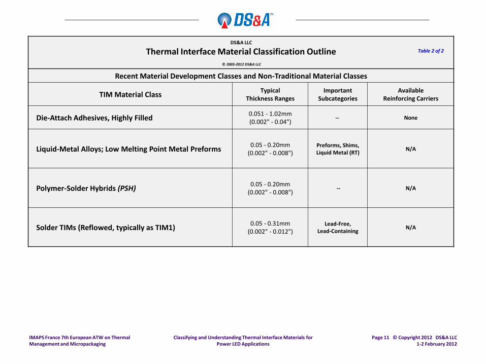
Thermal Interface Material Classification Outline © 2003-2012 DS&A LLC
Recent Material Development Classes and Non-Traditional Material Classes
TIM Material Class Typical
Thickness Ranges Important
Subcategories Available
Reinforcing Carriers
Die-Attach Adhesives, Highly Filled 0.051 - 1.02mm (0.002" - 0.04")
-- None
Liquid-Metal Alloys; Low Melting Point Metal Preforms 0.05 - 0.20mm
(0.002" - 0.008") Preforms, Shims, Liquid Metal (RT)
N/A
Polymer-Solder Hybrids (PSH) 0.05 - 0.20mm
(0.002" - 0.008") -- N/A
Solder TIMs (Reflowed, typically as TIM1) 0.05 - 0.31mm
(0.002" - 0.012") Lead-Free,
Lead-Containing N/A
Table 2 of 2
Classifying and Understanding Thermal Interface Materials for Power LED Applications
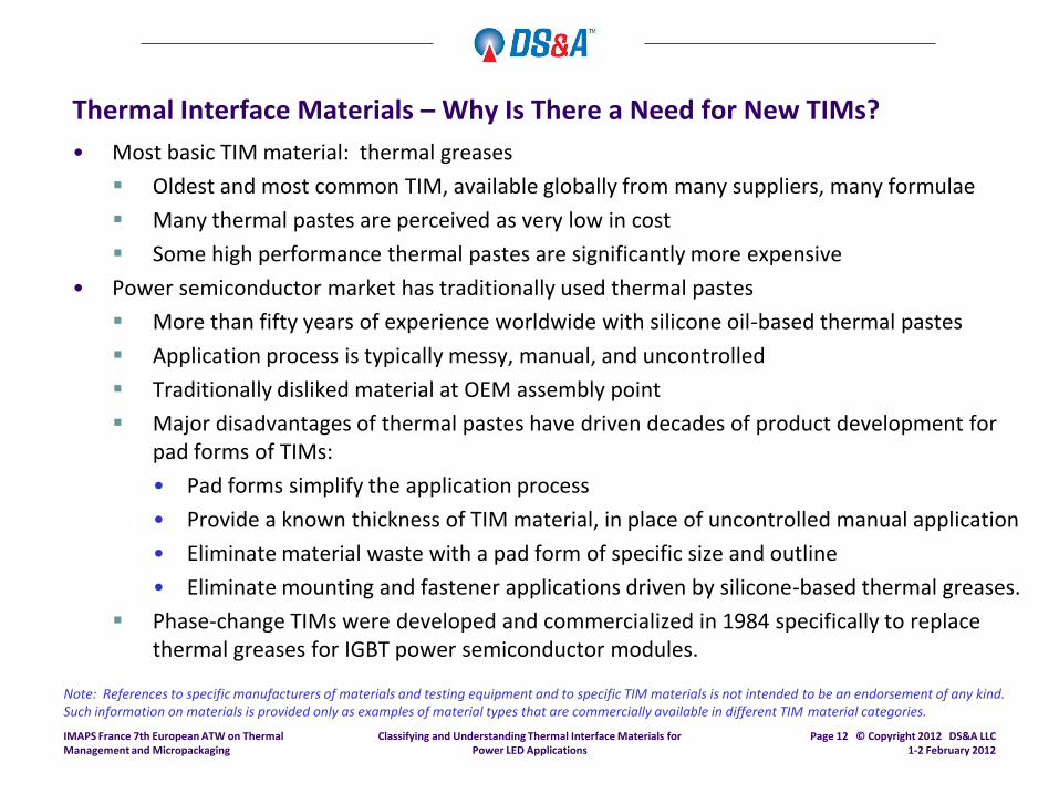
Thermal Interface Materials – Why Is There a Need for New TIMs?
• Most basic TIM material: thermal greases
Oldest and most common TIM, available globally from many suppliers, many formulae
Many thermal pastes are perceived as very low in cost
Some high performance thermal pastes are significantly more expensive
• Power semiconductor market has traditionally used thermal pastes
More than fifty years of experience worldwide with silicone oil-based thermal pastes
Application process is typically messy, manual, and uncontrolled
Traditionally disliked material at OEM assembly point
Major disadvantages of thermal pastes have driven decades of product development for pad forms of TIMs:
• Pad forms simplify the application process
• Provide a known thickness of TIM material, in place of uncontrolled manual application
• Eliminate material waste with a pad form of specific size and outline
• Eliminate mounting and fastener applications driven by silicone-based thermal greases.
Phase-change TIMs were developed and commercialized in 1984 specifically to replace thermal greases for IGBT power semiconductor modules.
Note: References to specific manufacturers of materials and testing equipment and to specific TIM materials is not intended to be an endorsement of any kind. Such information on materials is provided only as examples of material types that are commercially available in different TIM material categories.
IMAPS France 7th European ATW on Thermal Management and Micropackaging
Page 12 © Copyright 2012 DS&A LLC 1-2 February 2012

Classifying and Understanding Thermal Interface Materials for Power LED Applications
Thermal Interface Materials – Why Is There a Need for New TIMs?
• Disadvantages of thermal greases have led to parallel development paths in power semiconductor market:
1. Continued development of silicone-based and non-silicone thermal greases
• Attempts to address pump-out and migration reliability problems
• Development of specific patterns of thermal paste application by IGBT module manufacturers (e.g., Semikron, Infineon)
• Automation of application process with screen printing, other processes.
2. Rapid development of newer pad forms of alternative TIM materials:
• Phase-change TIMs in pad forms
• Phase-change TIMs in ingot form for automated screen printing processes
• Dielectric phase-change TIMs for non-isolated semiconductor packages
• Non-silicone-based “dry” thermal greases in pad forms
• Polymer-solder hybrids
• Metallic TIMs in pad form
3. Development of non-silicone oil thermal pastes and metallic TIMs to eliminate oils.
• Increasing operating temperatures of semiconductor die is another factor driving temperature requirements for TIM2.
IMAPS France 7th European ATW on Thermal Management and Micropackaging
Page 13 © Copyright 2012 DS&A LLC 1-2 February 2012

Classifying and Understanding Thermal Interface Materials for Power LED Applications
Importance of Thermal Conductivity
• Is thermal conductivity of a given material the only measure of overall thermal performance?
Three major factors determine overall thermal performance of a category of materials:
• Material thickness
• Percent of surface wetting achieved
• Thermal conductivity
The highest thermal conductivity value achievable does not necessarily imply a TIM material with the best overall performance.
Different application requirements drive different material design and chemistries:
• Example 1: Gap fillers are by definition very thick, as the primary purpose is to fill a very large air gap between two components:
• Example: Top surface of a heat dissipating component in an LED luminaire “can”.
• Gap may be 0.040”, limited clamping force
• Only a gap-filler can meet this requirement, with a relatively dense polymeric material of modest thermal conductivity – no grease, gel, or phase-change.
• Compressibility requirement for a limited clamping force over a large area can limit the percentage of high-conductivity filler
• Result is a very suitable gap-filler TIM with only modest thermal conductivity. IMAPS France 7th European ATW on Thermal Management and Micropackaging
Page 14 © Copyright 2012 DS&A LLC 1-2 February 2012

Classifying and Understanding Thermal Interface Materials for Power LED Applications
Importance of Thermal Conductivity
• Is thermal conductivity of a given material the only measure of overall thermal performance?
Different application requirements drive different material design and chemistries:
• Example 2: Phase-change compounds and PSHs function by limiting the thickness under applied clamping force to achieve:
• Minimum possible thickness under highest available clamping force;
• Maximum percentage surface wetting
• Compound can be handled at room temperature for positioning and placement
• Compound undergoes a phase-change transition at a designed temperature (e.g., 60°C) to a liquidus form
• Compound formulation is designed to prevent compound run-out at temperature.
• Example 3: Die-attach adhesives, highly-filled, used as TIM1:
• High relative percentage of silver filler used to increase overall thermal conductivity
• Metallic filler content may be required to achieve specified electrical conductivity
• Limit on filler percentage is driven by requirements for paste dispensing and stiffness and CTE mismatch requirements within finished semiconductor package.
• Filler percentage determines overall TIM1 thermal conductivity.
IMAPS France 7th European ATW on Thermal Management and Micropackaging
Page 15 © Copyright 2012 DS&A LLC 1-2 February 2012

Classifying and Understanding Thermal Interface Materials for Power LED Applications
Thermal Conductivity Comparison
Material Thermal Conductivity (W/mK)
or Apparent Thermal Conductivity*
Copper (for reference) 385
Indium and other metallic TIMs 86
LMA (Liquid Metal Alloy) 20
Thermal Pastes 0.3 – 7.0
Phase-Change Compounds and PSHs 0.3 – 1.0 (typical)
[Carrier (if present): 75]
Relative thermal conductivity for common thermal management materials:
* Certain pre-form materials contain an aluminum or other metallic foil carrier with compound coating on one or both surfaces.
IMAPS France 7th European ATW on Thermal Management and Micropackaging
Page 16 © Copyright 2009 DS&A LLC March 10-12, 2009
Classifying and Understanding Thermal Interface Materials for Power LED Applications
TIM Material Categories
IMAPS France 7th European ATW on Thermal Management and Micropackaging
Page 17 © Copyright 2012 DS&A LLC 1-2 February 2012

Classifying and Understanding Thermal Interface Materials for Power LED Applications
Solders: Direct Die Solder Attach
• Indium alloy solders are now used for high-volume TIM1 applications for server processors and processors:
Highly compliant for CTE matching with current copper lids for processors on organic substrates
Direct contact to back-side metallization (BSM) on silicon die
Relatively high thickness to compensate for package variation and CTE mismatch
Well-characterized material applied in automated processes with surrounding IP
Highly specific to application
• Cost and assembly process requirements may suggest that these materials are most useful in:
High-volume high power LED applications where process automation can be justified.
Very specialized power LED market applications where maximum thermal performance is required through a materials stack.
IMAPS France 7th European ATW on Thermal Management and Micropackaging
Page 18 © Copyright 2012 DS&A LLC 1-2 February 2012

Classifying and Understanding Thermal Interface Materials for Power LED Applications
Solders: RNT Technologies
• Recently-announced materials and process development for unique metal joining process as TIM1 solder material:
Fluxless, lead-free joining process.
Joining achieved with lead-free Indium solders at room temperature using reactive multilayer foils.
Activation process between solder layers generated heat via a reaction within the foil.
Localized heat of reaction melts solder to form bond.
Appropriate for silicon-to-metal joining as TIM1.
With or without gold plating requirement.
Low interface thermal resistances achieved.
• Average bond line thickness achieved of 170 microns.
• Thermal impedance achieved (120 micron BLT): 0.040°C-cm2/W
Source: RNT Technologies
IMAPS France 7th European ATW on Thermal Management and Micropackaging
Page 19 © Copyright 2009 DS&A LLC March 10-12, 2009

Classifying and Understanding Thermal Interface Materials for Power LED Applications
Liquid Metal Alloys (LMAs)
• Significant IP developed in this area by several companies.
• Initial product offered by Thermagon in 2001 as T-LMA™
• Principal constituent alloys include bismuth-tin-indium and similar
• Phase-change at temperature, pressure.
• Suppliers include:
Bergquist Company
Laird (Thermagon, Warth)
Others
• Performance indicates best alternative to solder attach (DDSA) process for TIM1.
Refer to slides following for relative test performance comparison among LMA materials and near-metallic TIMs.
Refer to references for additional information.
IMAPS France 7th European ATW on Thermal Management and Micropackaging
Page 20 © Copyright 2012 DS&A LLC 1-2 February 2012
Classifying and Understanding Thermal Interface Materials for Power LED Applications
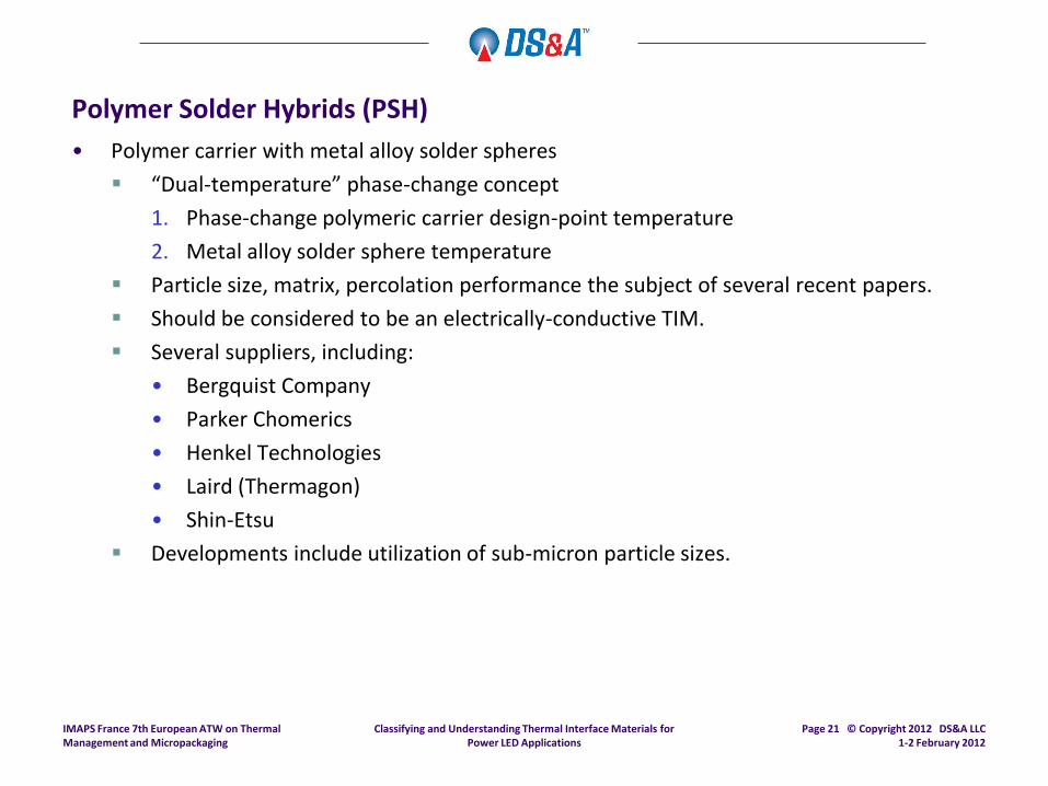
Polymer Solder Hybrids (PSH)
• Polymer carrier with metal alloy solder spheres
“Dual-temperature” phase-change concept
1. Phase-change polymeric carrier design-point temperature
2. Metal alloy solder sphere temperature
Particle size, matrix, percolation performance the subject of several recent papers.
Should be considered to be an electrically-conductive TIM.
Several suppliers, including:
• Bergquist Company
• Parker Chomerics
• Henkel Technologies
• Laird (Thermagon)
• Shin-Etsu
Developments include utilization of sub-micron particle sizes.
IMAPS France 7th European ATW on Thermal Management and Micropackaging
Page 21 © Copyright 2012 DS&A LLC 1-2 February 2012
Classifying and Understanding Thermal Interface Materials for Power LED Applications
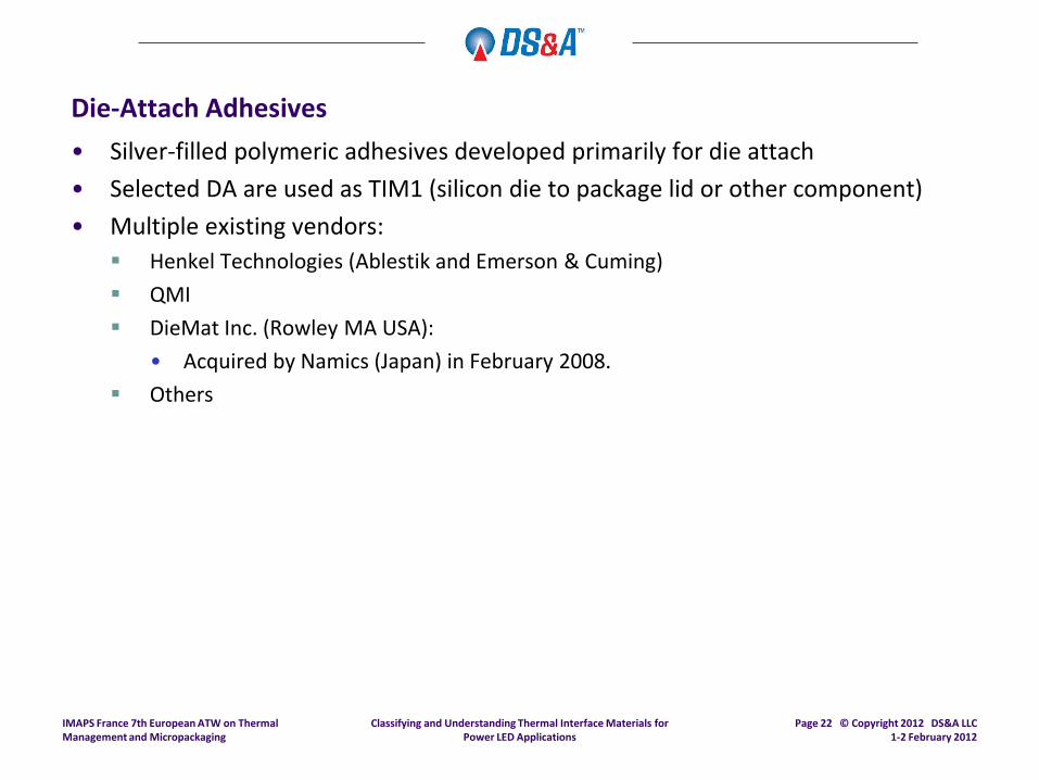
Die-Attach Adhesives
• Silver-filled polymeric adhesives developed primarily for die attach
• Selected DA are used as TIM1 (silicon die to package lid or other component)
• Multiple existing vendors:
Henkel Technologies (Ablestik and Emerson & Cuming)
QMI
DieMat Inc. (Rowley MA USA):
• Acquired by Namics (Japan) in February 2008.
Others
IMAPS France 7th European ATW on Thermal Management and Micropackaging
Page 22 © Copyright 2012 DS&A LLC 1-2 February 2012

Classifying and Understanding Thermal Interface Materials for Power LED Applications
Gels
• Cross-linked polymers requiring temperature-activated cure:
Example: Lord Thermoset Gelease™ family
Not common for LED applications
System Filler Type Viscosity Thixotropic Index Thermal Impedance
(°C-cm2/W)
Gelease A Mineral 400,000 4.4 0.77
Gelease B Metal 57,000 4.0 0.58
Gelease C Metal 61,000 3.6
0.39
IMAPS France 7th European ATW on Thermal Management and Micropackaging
Page 23 © Copyright 2009 DS&A LLC March 10-12, 2009
Note Gelease is a trademark of Lord Corporation

Classifying and Understanding Thermal Interface Materials for Power LED Applications
Thermal Greases • Most traditional TIM material:
Silicone-based paste format with a variety of fillers
Typically applied in manual application or semi-automated process
High-volume screen printing applications
• Typically viewed as lowest-cost TIM material of any kind.
• Referred to generally as “thermal paste”, “thermal compound”, “thermal grease”.
• User costing typically does not account for waste, clean-up, labor cost for application: Low material cost does not accurately describe total applied cost.
Makes accurate cost comparisons to alternative TIM materials difficult.
Bond line thickness generally predominates in thermal impedance performance, not filler material conductivity.
Filler particle size is generally more critical than filler conductivity.
High thermal conductivity fillers may result in higher thermal impedance, not lower.1
Development of a material with greatest ease of application may outweigh thermal impedance performance as the primary development target for many TIM2 applications.
• Example: AOS MicroFaze™ dry pad form, supplied on rolls for rapid application.
IMAPS France 7th European ATW on Thermal Management and Micropackaging
Page 24 © Copyright 2012 DS&A LLC 1-2 February 2012
1 Source: Prasher, Intel ATD, “Thermal Resistance of Particle-Laden Polymeric Thermal Interface Materials”, ITS 2003

Classifying and Understanding Thermal Interface Materials for Power LED Applications
Thermal Greases
• Large number of vendors worldwide Shin-Etsu G-749, G-751: commonly referenced in North America for processors
Shin-Etsu SMX-7762, SMX-7783D: highest performance, high cost
Laird (Thermagon) T-Grease 2500
AOS:
• 52137: Non-silicone thermal compound
• MicroFaze® 3A4: Non-silicone dry pad form of thermal compound
Bergquist TIC-7500: highest thermal conductivity value(7.0W/mK) claimed for any thermal grease
Bergquist TIC-2500: thermal conductivity (2.5W/mK)
Bergquist TIC-1000
Dow Corning:
• DC-340: Traditional market leader for older discretepower transistor applications
• DC-5021, D-5022, D-5026
Electrolube HTC
Wacker Chemie P12
IMAPS France 7th European ATW on Thermal Management and Micropackaging
Page 25 © Copyright 2012 DS&A LLC 1-2 February 2012

Classifying and Understanding Thermal Interface Materials for Power LED Applications
Phase-Change Materials (PCTIM)
• Phase-change TIMs (PCTIMs): Polymeric compound changes phase from a solid to a liquid at a design point temperature (typically 51°C or 60°C).
• Many TIM vendors now offer phase-change materials in pad forms Designed to simply assembly practices
Eliminate traditional problems with silicone thermal greases
Well-accepted by manufacturing and process control for:
• Ease of use in assembly, for either manual or automated placement.
• Pre-determined volume of compound in pad form, pre-determined bond line thickness.
• Screen-printable dry format phase-change TIMs are excellent high-volume TIM2 materials:
Low-cost, automated process that is very suitable for power LED applications
High-performance phase-change compounds
Available from several vendors:
• Henkel Powerstrate 51F
• Honeywell Electronic Materials PCM-45F
IMAPS France 7th European ATW on Thermal Management and Micropackaging
Page 26 © Copyright 2012 DS&A LLC 1-2 February 2012
Classifying and Understanding Thermal Interface Materials for Power LED Applications
Elastomeric and Dielectric Pads
• Offered by dozens of TIM vendors and resellers worldwide.
• Intensely price competitive.
• Application requirements are much simplified (compared to greases, gels, LMAs, other TIM material categories).
• Minimum performance in many thicker elastomeric pads
• Primary cost factor is cost of conversion, not cost of material production.
• Dielectric pads have a major reliability and liability component:
So-called “cut-through” for sharp particle protrusion into dielectric carrier such as Dupont® Kapton™ or KaptonMT™.
• Cost of dielectric carrier materials impacts overall TIM cost.
UL/CSA certifications are critical – primarily referencing DuPont Kapton UL “yellow card”.
Kapton™ and Kapton MT™ are trademarks of Dupont
IMAPS France 7th European ATW on Thermal Management and Micropackaging
Page 27 © Copyright 2012 DS&A LLC 1-2 February 2012

Classifying and Understanding Thermal Interface Materials for Power LED Applications
Pressure-Sensitive Adhesives (PSAs)
• Typically supplied as a pre-form on rolls, with release liner
• Many existing vendors
• Many performance levels for existing materials
• Application requirements are simplified.
• Presence of an adhesive coating on one or both sides severely impacts thermal impedance:
Primary purpose is to simply an assembly process, not maximize thermal impedance.
Adhesive coating eliminates need for mechanical clamping, the key factor for use.
IMAPS France 7th European ATW on Thermal Management and Micropackaging
Page 28 © Copyright 2012 DS&A LLC 1-2 February 2012
Classifying and Understanding Thermal Interface Materials for Power LED Applications
Gap-Fillers
• General statements:
Purpose of these materials is to fill a large air gap between a heat source and a convenient metal surface
Relative high thickness precludes high performance relative to phase-change, thermal greases, LMAs, PSHs:
• Many materials available with modest thermal performance.
• Compressibility is an important determinant in material selection for a given application
• Surfaces of gap-fillers may be tacky, to reduce interfacial resistance.
• Protection of surfaces with release liners prior to application is important to prevent dust, particulate accumulation.
• Application requirements are specific to individual material types.
• Very common for power LED applications:
Luminaire lighting fixtures: heat transfer from LED baseplate to luminaire “can” for heat transfer to ambient air
Very commonly used as TIM2 for projector light sources and other power LED applications.
IMAPS France 7th European ATW on Thermal Management and Micropackaging
Page 29 © Copyright 2012 DS&A LLC 1-2 February 2012

Classifying and Understanding Thermal Interface Materials for Power LED Applications
Gap-Fillers
• Compressibility is a key characteristic of gap-filler:
Ability to deflect at low pressures
Minimum pressure is important
Relative high thermal conductivity is important because of the relatively thick nature of a gap-filler
Young’s Modulus of material is strongly affected by use of a high percentage of the high thermal conductivity filler constituent.
• Review compressibility information provided by vendors for details
Example: Bergquist Company Application Note 116:
IMAPS France 7th European ATW on Thermal Management and Micropackaging
Page 30 © Copyright 2012 DS&A LLC 1-2 February 2012
Classifying and Understanding Thermal Interface Materials for Power LED Applications
Nanomaterials
• Nanotechnologies and nanomaterials applied to TIMs:
Substantial public discussion of nanomaterials for TIM and thermal applications over 2003 – 2009.
Few materials commercialized to date.
• Many university and research development programs to evaluate forms of nanomaterials which may offer:
High thermal conductivity as stand-alone TIM materials in various forms
Use of nanomaterials as high thermal conductivity constituents in TIM materials such as thermal greases and compounds.
• Current US programs to develop significant improvements in TIM material performance:
Three programs are utilizing arrays of carbon nanotubes grown on a carrier with a liquid metal or metal infiltration
One program utilizing large number of micro copper springs
Performance results currently equal to existing metallic TIM materials and reflowed indium solders.
Manufacturability continues to be a major challenge, as is testing equipment resolution.
IMAPS France 7th European ATW on Thermal Management and Micropackaging
Page 31 © Copyright 2012 DS&A LLC 1-2 February 2012

Classifying and Understanding Thermal Interface Materials for Power LED Applications
Liquid Metal Alloys
• Commercial LMA products:
Designed with retention mechanism as a pad form of material. Examples:
• Enerdyne Solutions Indigo™
• Indium Corporation Indalloy 19 – applied in solid form, phase-change at 60°C
• Others
Liquid metals, designed for phase-change at 10°C:
• Indium Corporation Indalloy 51
• Indium Corporation Indalloy 46L
• Gallium
• Thermal conductivities to 86W-mK
• Proprietary retention mechanism available
Photograph: Indium Corporation
Liquid indium alloy
IMAPS France 7th European ATW on Thermal Management and Micropackaging
Page 32 © Copyright 2012 DS&A LLC 1-2 February 2012

Classifying and Understanding Thermal Interface Materials for Power LED Applications
Metallic Thermal Interface Materials
• Soft metal alloys (“SMA-TIM”):
Flat foils and preforms used as TIM2:
• Typical products used in many traditional applications
• Referred to historically as “solder shims” in RF device applications for RF amplifiers
• Traditional flat foils
• Available in flat sheet form, flat sheet preforms, preform “window frames”
Indium Corporation Heat-Spring®
• Compressible metallic TIM materials
• Available in die-cut preforms
• Available in several versions and several thicknesses
• Advantages: Stability – No silicone oils, no bake-out or pump-out issues
High thermal conductivity and low bulk resistance—less sensitive to thickness change
High X-Y heat spreading capability as a metal
Inherent gap-filling capability for co-planarity issues: +/- 75um
Complies with CTE mismatch for different substrates and heat sink materials
Heat-Spring® is a registered mark of Indium Corporation
IMAPS France 7th European ATW on Thermal Management and Micropackaging
Page 33 © Copyright 2012 DS&A LLC 1-2 February 2012
Classifying and Understanding Thermal Interface Materials for Power LED Applications
TIM Material Performance Testing Procedures
IMAPS France 7th European ATW on Thermal Management and Micropackaging
Page 34 © Copyright 2009 DS&A LLC March 10-12, 2009
Classifying and Understanding Thermal Interface Materials for Power LED Applications
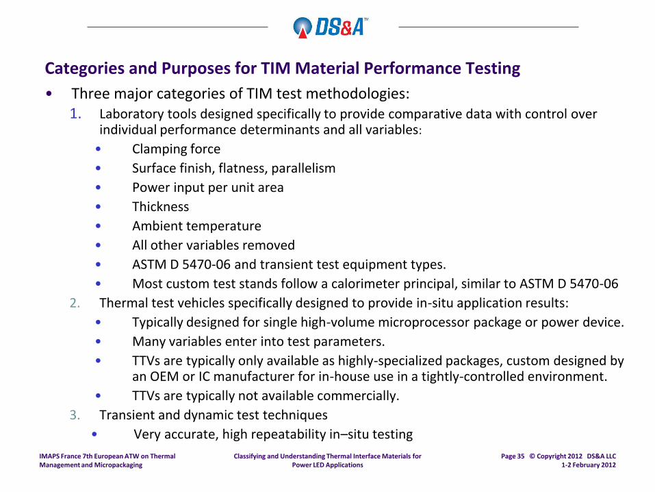
Categories and Purposes for TIM Material Performance Testing
• Three major categories of TIM test methodologies: 1. Laboratory tools designed specifically to provide comparative data with control over
individual performance determinants and all variables:
• Clamping force
• Surface finish, flatness, parallelism
• Power input per unit area
• Thickness
• Ambient temperature
• All other variables removed
• ASTM D 5470-06 and transient test equipment types.
• Most custom test stands follow a calorimeter principal, similar to ASTM D 5470-06
2. Thermal test vehicles specifically designed to provide in-situ application results:
• Typically designed for single high-volume microprocessor package or power device.
• Many variables enter into test parameters.
• TTVs are typically only available as highly-specialized packages, custom designed by an OEM or IC manufacturer for in-house use in a tightly-controlled environment.
• TTVs are typically not available commercially.
3. Transient and dynamic test techniques
• Very accurate, high repeatability in–situ testing
IMAPS France 7th European ATW on Thermal Management and Micropackaging
Page 35 © Copyright 2012 DS&A LLC 1-2 February 2012

Classifying and Understanding Thermal Interface Materials for Power LED Applications
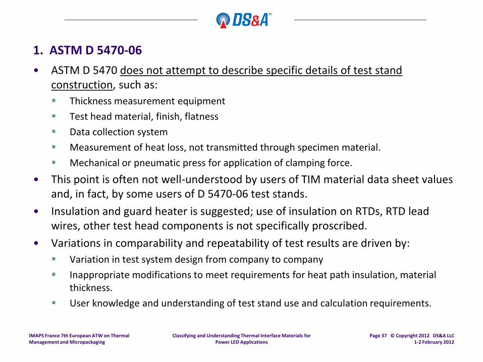
1. ASTM D 5470-06
• ASTM D 5470 was developed and published in 1984.
• Primary authors (both now retired): Mike DeSorgo, Parker Chomerics, USA
Herb Fick, The Bergquist Company, USA
• Newest methodology revision released in 2006 as ASTM D 5470-06.
• Source: ASTM International, West Conshohocken PA USA Website: www.astm.org Email inquiries: [email protected]
• Primary intended purpose: Thermal impedance and thermal conductivity test methodology for use with rigid and
semi-rigid thermal interface materials (electrically insulating and non-insulating).
Latest modifications address testing for non-rigid materials (i.e., PCTIMs, greases).
• Use of a test stand designed to follow latest revision (ASTM D 5470-06) for many materials requires modification of test stand: Mechanism to measure sample thickness under pressure.
Containment systems for liquidous and other non-rigid, non-uniform materials.
• ASTM D 5470-06 is a test methodology using the calorimeter principle.
IMAPS France 7th European ATW on Thermal Management and Micropackaging
Page 36 © Copyright 2012 DS&A LLC 1-2 February 2012
Classifying and Understanding Thermal Interface Materials for Power LED Applications
1. ASTM D 5470-06
• ASTM D 5470 does not attempt to describe specific details of test stand construction, such as:
Thickness measurement equipment
Test head material, finish, flatness
Data collection system
Measurement of heat loss, not transmitted through specimen material.
Mechanical or pneumatic press for application of clamping force.
• This point is often not well-understood by users of TIM material data sheet values and, in fact, by some users of D 5470-06 test stands.
• Insulation and guard heater is suggested; use of insulation on RTDs, RTD lead wires, other test head components is not specifically proscribed.
• Variations in comparability and repeatability of test results are driven by:
Variation in test system design from company to company
Inappropriate modifications to meet requirements for heat path insulation, material thickness.
User knowledge and understanding of test stand use and calculation requirements.
IMAPS France 7th European ATW on Thermal Management and Micropackaging
Page 37 © Copyright 2012 DS&A LLC 1-2 February 2012

2. Thermal Test Vehicle (TTV) Configuration
Heat sink
TIM test sample Die
Substrate
Thermocouple Probe
16 RTD Sensors
Classifying and Understanding Thermal Interface Materials for Power LED Applications
IMAPS France 7th European ATW on Thermal Management and Micropackaging
Page 38 © Copyright 2012 DS&A LLC 1-2 February 2012

Classifying and Understanding Thermal Interface Materials for Power LED Applications
2. Thermal Test Vehicles (TTVs) for Precision In-Situ Testing
• Comparative results for recent high performance TIM materials – increased pressure:
Source: DS&A LLC (2007, 2010) IMAPS France 7th European ATW on Thermal Management and Micropackaging
Page 39 © Copyright 2009 DS&A LLC March 10-12, 2009

Classifying and Understanding Thermal Interface Materials for Power LED Applications
3. Development of Dynamic and Transient Test Methodologies
• Descriptions of reasoning and goals provided in Electronics Cooling Magazine (November 2003).
• Proposed by Clemens Lasance as a function of JEDEC JC15.1 committee:
Source: C. Lasance, C.T. Murray, D. Saums, M. Rencz, “Challenges in Thermal Interface Material Testing”, Proceedings of IEEE 22nd Semitherm Conference, Dallas TX USA, March 13-15, 2006.
IMAPS France 7th European ATW on Thermal Management and Micropackaging
Page 40 © Copyright 2012 DS&A LLC 1-2 February 2012

Classifying and Understanding Thermal Interface Materials for Power LED Applications
3. Transient Testing Techniques for In-Situ Testing
• Transient testing techniques for thermal interface material testing measure temperature increases as a function of time:
Utilizes temperature sensors in a fixture
Thermal transient of the fixture is measured
Mathematical computations referred to as structure functions
Cumulative structure function yields the sum of thermal capacitances.
Changes in slope represent either specific material or increase in cross-sectional area, or both.
Thermal resistance value derived from slope for TIM specimen
Thermal conductivity value is proportional to slope.
Output from system can be:
• Thermal resistance and impedance
• Thermal conductivity
• Extremely capable test instrument, useful for package characterization.
• PowerLED test module available. Photograph: MicReD Ltd. (Mentor Graphics), Budapest, Hungary MicReD Ltd. T3ster™ Transient Tester System Unit
IMAPS France 7th European ATW on Thermal Management and Micropackaging
Page 41 © Copyright 2012 DS&A LLC 1-2 February 2012

Classifying and Understanding Thermal Interface Materials for Power LED Applications
TIM Material Life and Reliability Testing
IMAPS France 7th European ATW on Thermal Management and Micropackaging
Page 42 © Copyright 2009 DS&A LLC March 10-12, 2009

Classifying and Understanding Thermal Interface Materials for Power LED Applications
Why is Life Testing Important?
• Thermal resistance performance over time, temperature, and CTE expansion/contraction is critical to performance of very thin TIM materials.
• Traditional problems with silicone-based thermal greases are well-documented:
“Pump-out” in thermal and power cycling
Migration of silicone oils, causing dry-out
• Newer material developments continue to target these traditional problems.
• Example of results shown (next page):
Compressible metallic TIM comparison to silicone thermal grease
In-situ application test using microprocessor TTV (silicon die backside surface to heat sink surface)
3,000-hour bake test in clamped condition
IMAPS France 7th European ATW on Thermal Management and Micropackaging
Page 43 © Copyright 2012 DS&A LLC 1-2 February 2012

Classifying and Understanding Thermal Interface Materials for Power LED Applications
SMA-TIM Baseline Grease
3108 Hr. @90°C 3056 Hr. @90°C
88 - 90
86 - 88
84 - 86
82 - 84
80 - 82
78 - 80
76 - 78
74 - 76
72 - 74
70 - 72
68 - 70
66 - 68
64 - 66
62 - 64
60 - 62
TTV Profile Comparison: Bake 3000 Hours
Data source: Indium Corporation
Temperature (°C)
IMAPS France 7th European ATW on Thermal Management and Micropackaging
Page 44 © Copyright 2012 DS&A LLC 1-2 February 2012

Classifying and Understanding Thermal Interface Materials for Power LED Applications
End of Line Performance
• End of Line Thermal Resistance
TTV testing
• Assembly repeatability (variability in TTV)
• Thermal profiling and uniformity
• Performance against baseline thermal grease
In-situ testing – replicate exact applications conditions:
• Assembly repeatability
• Performance against baseline thermal grease or other qualified TIM
IMAPS France 7th European ATW on Thermal Management and Micropackaging
Page 45 © Copyright 2009 DS&A LLC March 10-12, 2009

Classifying and Understanding Thermal Interface Materials for Power LED Applications
Power Cycling Test Results: 3-Mil SMA vs. Thermal Grease, PCTIM
Data source: Indium Corporation
Silicone grease
PCTIM
SMA Indium 3-mil
IMAPS France 7th European ATW on Thermal Management and Micropackaging
Page 46 © Copyright 2009 DS&A LLC March 10-12, 2009

Classifying and Understanding Thermal Interface Materials for Power LED Applications
Thermal Test Equipment Vendors
Analysis Tech Thermal Impedance Test Stand John Sofia, President Wakefield MA USA
MicReD Ltd. Transient Thermal Impedance Test Instrument Subsidiary of Mentor Graphics Corporation MicReD T3str™ TIM Test Stand Budapest, Hungary Marta Rencz, CEO Email: [email protected] Gabor Farkas, Technical Director: Email: [email protected] Web: www.micred.com Thermal Engineering Associates, Inc. Thermal Impedance Test Stand Bernie Siegal, President Mountain View CA USA Tel: 650-961-5900 Email: [email protected] Web: www.thermengr.com
IMAPS France 7th European ATW on Thermal Management and Micropackaging
Page 47 © Copyright 2012 DS&A LLC 1-2 February 2012

Classifying and Understanding Thermal Interface Materials for Power LED Applications
References – LED Thermal and Packaging Topics
G. Farkas, Q. van Voorst Vader, A. Poppe, Gy. Bbognar: Thermal Investigation of High Power Optical Devices by Transient Testing, Proceedings of the 9th THERMINIC Conference, Aix-en-Provence, France, 2003.
A. Francois-Saint-Cyr, Mentor Graphics Mechanical Analysis Division: Transient Thermal Measurement of Electronic Components and Radiometric Characterization of LEDs, IESF (Integrated Electrical Solutions Forum) Automotive 2011, Dearborn MI USA, June 2, 2011.
A. Gasse, S. LaBau, S. Bernabe, P. Grosse, H. Ribot, CEA LETI: Thermal Resistance Measurements on Chip on Board LED Packaging, IMAPS Device Packaging Conference 2009, Fort McDowell AZ USA, March 9-12, 2009
OSRAM Opto Semiconductors: Mounting Guideline for High Power Light Sources of the OSTAR® LED Product Family, Application Note, May 2006, www.osram-os.com.
OSRAM Opto Semiconductors: Processing of OSRAM Opto Semiconductors LEDs, Application Note, February 10, 2005, www.osram-os.com.
J. Petroski, GELcore: Cooling of High Brightness LEDs: Developments, Issues, and Challenges, RTI Next Generation Thermal Management Materials and Systems Conference, June 15-17, 2005
K. Slob, et. al, Philips Applied Technologies: Bonding a LED Substrate to a Heat Spreader: More than a Matter of Low Thermal Resistance, IMAPS Device Packaging Conference 2009, Fort McDowell AZ USA, March 9-12, 2009.
T. Treurniet, V. Lammens, Philips Lighting: Thermal Management in Color Variable Multi-Chip LED Modules, Procedings of IEEE 22nd SemiTherm Conference, Dallas TX USA, March 3, 2006.
IMAPS France 7th European ATW on Thermal Management and Micropackaging
Page 48 © Copyright 2012 DS&A LLC 1-2 February 2012

Classifying and Understanding Thermal Interface Materials for Power LED Applications
Useful TIM Characterization Publications and References
ASTM International, ASTM D5470-95, Standard Test Method for Thermal Transmission Properties of Thin Thermally Conductive Solid Electrical Insulation Materials, ASTM, Philadelphia PA USA, 1995.
N.F. Dean, E. Gettings: Experimental Testing of Thermal Interface Materials on Non-Planar Surfaces, Proceedings of IEEE 13th Semitherm Conference, San Diego CA USA, March 1998.
European Power Semiconductor and Electronics Company (Eupec): Application Note, Comparison of Thermal Compounds and Heat Conducting Foils, Munich, Germany, 2000.
K. Hanson, ASTM D 5470 TIM Material Testing, Proceedings of IEEE 22nd Semitherm Conference, Dallas TX USA, March 13-15, 2006.
R. N. Jarrett, C.K. Merritt, J.P. Ross, J. Hisert, Indium Corporation: Comparison of Test Methods for High-Perfor-mance Thermal Interface Materials, IEEE Semitherm 23 Conference, San Jose CA USA, March 21, 2007.
C. Lasance, C.T. Murray, D. Saums, M. Rencz, Challenges in Thermal Interface Material Testing, Proceedings of IEEE 22nd Semitherm Conference, Dallas TX USA, March 13-15, 2006.
A. Poppe, V. Székély: Dynamic Temperature Measurements: Tools Providing a Look Into Package and Mount Structures, Electronic Cooling Magazine, Vol. 8, No. 2, May 2002.
R. Rauch, Test Methods for Characterizing the Thermal Transmission Properties of Phase-Change Thermal Interface Materials, Electronics Cooling Magazine, November 2000.
M. Rencz, et al.: Determining Partial Thermal Resistances with Transient Measurements and Using the Method to Detect Die Attach Discontinuities, Proceedings of IEEE 17th Semitherm Conference, San Jose CA USA, March 2001.
IMAPS France 7th European ATW on Thermal Management and Micropackaging
Page 49 © Copyright 2012 DS&A LLC 1-2 February 2012

Classifying and Understanding Thermal Interface Materials for Power LED Applications
Useful TIM Characterization Publications and References
D. Saums, DS&A LLC: Developments with Metallic TIM Materials, Electronics Cooling Magazine, Volume 13, No. 2, May 2007, pp. 28-32.
R. Shih, C. E. Bash, Hewlett-Packard Laboratories: Dynamic Characterization of Thermal Interface Material for Electronic Cooling, Proceedings of ASME Interpack 2003, Maui, Hawaii USA, July 6-11, 2003.
J.-P. Sommer, B. Michel, Fraunhofer Institute IZM, Berlin, Germany; Reinhold Bayerer, Roman Tschirbs, Infineon Technologies AG, Warstein, Germany: Base Plate Optimization for High-Power IGBT Modules, CIPS 2008 Conference, Nürnberg, Germany, March 2008.
Y. St. Martin, Theodore van Kassel, IBM Research Division: High Performance Liquid Metal Thermal Interface for Large Volume Production, IMAPS Symposium 2007, San Jose CA USA, November 2007.
P. Szabo, et al.: Transient Junction-to-Case Thermal Resistance Measurement Methodology of High Accuracy and Repeatability, Proceedings of 10th THERMINIC Conference, Côté d’Azur, France, Sept. 29-Oct. 1, 2004.
J. Tzeng, T. Weber, D. Krasowski: Technical Review on Thermal Conductivity Measurement Techniques for Thin Thermal Interfaces, Proceedings of IEEE 16th Semitherm Conference, San Jose CA USA, March 2000.
IMAPS France 7th European ATW on Thermal Management and Micropackaging
Page 50 © Copyright 2012 DS&A LLC 1-2 February 2012

Classifying and Understanding Thermal Interface Materials for Power LED Applications
100 High Street David L. Saums, Principal Amesbury MA 01913 USA E: [email protected] Tel: +1 978 499 4990 Website: www.dsa-thermal.com Business and product development strategy development for electronics thermal management: advanced thermal materials, components, and thermal systems.
Contact Information
IMAPS France 7th European ATW on Thermal Management and Micropackaging
Page 51 © Copyright 2009 DS&A LLC March 10-12, 2009