Classification: Internal - equinor.com · Classification: Internal Status: Final report –...
139
Transcript of Classification: Internal - equinor.com · Classification: Internal Status: Final report –...


Classification: Internal Status: Final report – released Date: 4.1.2017
Investigation of: Well Control Incident Troll G-4 (Songa Endurance)
Security Classification: Internal Status: Final report – released Page 2 of 114
Contents 1 Summary........................................................................................................................................................ 4 1.1 The incident .................................................................................................................................................... 4 1.2 Consequences ................................................................................................................................................ 4 1.3 Causes ............................................................................................................................................................ 4 1.4 Work processes, requirements and barriers ................................................................................................... 5 1.5 Positive aspects ............................................................................................................................................ 11 1.6 Recommendations for learning ..................................................................................................................... 12 2 Investigation mandate and investigation execution................................................................................ 14 2.1 Mandate ........................................................................................................................................................ 14 2.2 Investigation work ......................................................................................................................................... 15 3 Background information ............................................................................................................................ 16 3.1 Unit / site ....................................................................................................................................................... 16 3.2 Organisation.................................................................................................................................................. 19 3.3 Technical/operational descriptions................................................................................................................ 20 4 Sequence of events .................................................................................................................................... 27 4.1 Events before the plug & abandonment operation on G-4............................................................................ 27 4.2 Events during the plug & abandonment operation ........................................................................................ 32 4.3 Emergency preparedness ............................................................................................................................. 44 4.4 Normalizing work carried out from 15.10 until 26.10.2016............................................................................ 46 5 Consequences ............................................................................................................................................ 49 5.1 Actual consequences .................................................................................................................................... 52 5.2 Classification according to matrix for well incidents, GL0455 ....................................................................... 53 5.3 Potential consequences ................................................................................................................................ 54 5.4 Assessment of major accident risk ............................................................................................................... 58 5.5 Incident classification .................................................................................................................................... 58 6 Causes ......................................................................................................................................................... 59 6.1 Causes linked to Flow Control Valve as primary barrier instead of deep set plug ........................................ 60 6.2 Causes linked to Gas Lift Valve / Flow Control Valve unintentionally cycled open ...................................... 64 6.3 Causes linked to Tubing Hanger released without knowing status of primary barrier .................................. 67 6.4 Causes linked to HC leak ~50 kg/sec until Annular Preventer was closed ................................................... 69 7 Work processes, requirements and barriers ............................................................................................ 74 7.1 Work processes and requirements ............................................................................................................... 74 7.2 Barriers ......................................................................................................................................................... 79 8 Similar incidents ......................................................................................................................................... 83 9 Recommendations for learning ................................................................................................................. 85 9.1 Immediate actions performed after the incident ............................................................................................ 85 9.2 Learning and recommendations ................................................................................................................... 86 11 References................................................................................................................................................... 92 App A Interview list ................................................................................................................................................ 94 App B Alert sent to Petroleum Safety Authority (Ptil) in Norwegian only ......................................................... 95

Classification: Internal Status: Final report – released Date: 4.1.2017
Investigation of: Well Control Incident Troll G-4 (Songa Endurance)
Security Classification: Internal Status: Final report – released Page 3 of 114
App C Different alternatives for well control, dated 18.10.2016 ......................................................................... 97 App D Classification matrix for safety impact ..................................................................................................... 99 App E Organisational charts ............................................................................................................................... 100 App F Work processes for Plug & Abandonment ............................................................................................. 103 App G Description of Flow Control and Gas Lift Valves ................................................................................... 107 App H Choke Manifold line-up sketch ................................................................................................................ 110 App I Versions of Detailed Operations Plan 090 .............................................................................................. 111 App J Handover Certificate (from D&W to OMM).............................................................................................. 113 App K Gas hazard analysis, gas leak on Songa Endurance ............................................................................ 114

Classification: Internal Status: Final report – released Date: 4.1.2017
Investigation of: Well Control Incident Troll G-4 (Songa Endurance)
Security Classification: Internal Status: Final report – released Page 4 of 114
1 Summary
The main purpose of this investigation in hindsight of the incident is to contribute to constructive learning effect to prevent recurrence and to achieve an improvement of the safety level. The work is performed to the investigation team’s best ability, and is based on assessment of available knowledge and information. The investigation team has not made any assessment of legal aspects of the incident, including in relation to causes, liability or similar conditions.
1.1 The incident
Decision had been made to permanently Plug and Abandon (P&A) Well 31/2-G-4 BY1H/BY2H in the Troll field and prepare for a new multilateral; CY1H/CY2H/CY3H from well slot G-4. On 15 October 2016, during the P&A operations; when preparing to pull out with the production tubing, there was an influx of gas into the well that lasted about one minute before the annular valve in the BOP was closed. The string, consisting of production tubing down to 1277 m, tubing hanger, a tubing hanger retrieving tool and drillpipe to surface, was lifted up 6 m, pushed by the water column in the riser and the emerging gas. The initial gas leak rate has been calculated to ~48 kg/sec (when the riser was still water-filled) and increasing as the riser was gradually emptied for water, to maximum ~ 71 kg/sec (calculated rate for an empty riser) until the annular closed. The gas leak on surface lasted approximately one minute. There was no personnel injury due to the incident.
1.2 Consequences
The investigation team has classified the incident as a HSE incident with highest actual degree of seriousness Actual Red 1: Oil /Gas /flammable liquids leakages and Costs / losses. The reason for the classification is the rate of the gas leak > 10 kg/s and the economic loss due to down time during normalization. The incident has also been classified according to Statoil’s guideline GL0455, based on the Norwegian Oil and Gas Association’s recommendation NOG135 matrix for well control incidents, as Actual Red 1.2 – High HC influx rate. The incident is overall classified by highest degree of severity Actual Red 1.
1.3 Causes
The immediate causes to the incident were • decision to base primary barrier on valves that could cycle (open) instead of deep set plug • unintentional cycling (i.e. opening) of the barrier valves • releasing the tubing hanger without having the means to check for pressure below and without closing the
annular preventer in the BOP • the plan for pulling the tubing hanger did not cater for the possibility of failure of the deep barrier, i.e. the
operation was carried out without the required independency between barriers The operational procedure was changed the previous evening, 14 October 2016, to release the tubing hanger without closing the annular preventer valve in the blowout preventer. The investigation team considers it likely that the consequences of the incident had been reduced if the annular had been closed with reduced pressure before releasing the tubing hanger.

Classification: Internal Status: Final report – released Date: 4.1.2017
Investigation of: Well Control Incident Troll G-4 (Songa Endurance)
Security Classification: Internal Status: Final report – released Page 5 of 114
The investigation team considers that the underlying causes can be summarized to insufficient application of the Compliance and Leadership Model (C&L). There seems to have been insufficient handling of requirements and risks:
• when setting up the project team • during the execution phase • during change management • regarding two-barrier philosophy
Further, based on the fact that the P&A risk assessment is silent with regard to the risk of compromising of the well barrier through unintentional cycling of the valves, the investigation group finds that the robustness of the well barriers was not sufficiently examined, especially with regards to independence and monitoring. Changes in proven concepts require considerably more effort in the planning phase. Diversity in experience is an advantage, field- and equipment specific competence is necessary and thorough examination of the pros and cons of the proposed changes is important. This seems to have been underestimated when planning for use of flow control and gas lift valves as barrier in the P&A operation, instead of following standard procedure by using a deep set mechanical plug against the reservoir.
1.4 Work processes, requirements and barriers
The table below lists some of the relevant work processes for the P&A operation, and the status regarding compliance to requirements.
No Work process/
requirement Reference to requirements/ information
element Status
1
FR03 Drilling and well technology (D&W)
Fundamentals (excerpts of list) 1. Drilling and well shall have a capable organization for efficient planning and execution, and risk management. 3. Technical, operational and organizational barriers shall be established, monitored and maintained to ensure that no single failure can escalate into an unacceptable situation.
Weaknesses The planning of G-4 did not manage to see the risks involved in choosing an unproven method for barrier, using flow control valves on this type of XT (Vetco). The Troll Field teams have over time developed different operational practice than what is used by the rest of the company
2 DW203.01 Establish detailed planning project
I-102095 Drilling and well resources The composition of the project should reflect the scope of the work. Continuity from the previous phases should be emphasised when appointing resources. It is recommended to identify relevant professional expertise and to contact these as early as possible to ensure their participation.
Weaknesses As far as the investigation team knows, there was only one project member in Statoil’s “Songa Endurance” team, in addition to the Drilling Superintendent, with previous experience on Vetco wells. During planning of the G-4 well, this was raised as an issue, and a two-day seminar was held in cooperation with supplier with specific Vetco and Troll competence. The planning team still failed to identify the risk of using the FCVs as well barrier.

Classification: Internal Status: Final report – released Date: 4.1.2017
Investigation of: Well Control Incident Troll G-4 (Songa Endurance)
Security Classification: Internal Status: Final report – released Page 6 of 114
No Work process/
requirement Reference to requirements/ information
element Status
3 DW203.01 Establish detailed planning project
R-37451 Appoint project risk coordinator A project risk coordinator shall be appointed. The complexity of the project and the associated scope for risk management shall be considered to ensure sufficient capacity and risk management competence in this role.
Weaknesses Risk meetings were held, but did not manage to identify the new risk of having GLV/FCVs as barrier elements and therefore no actions were taken to mitigate the risk Relevant competence on Vetco wells was not present in all the risk meetings
4 DW203.09 Perform detailed engineering P&A
R-11035 Finalize well barrier schematics – Permanent P&A There shall be a well specific well barrier schematic (WBS) for any planned well operation, for each operational phase for the well barrier envelope, including WBS for planned permanent P&A. The well barrier schematics shall be established by using the templates in the well barrier schematic library
Weaknesses Relevant well specific well barrier schematics were prepared in the activity program for G-4, and the GLV / FCVs are marked as primary barriers in parts of the operation sequences. A control line or exhaust line from the valves is drawn up to the production packer, but not all the way through the tubing hanger in most of the WBS’s. This may have made it hard, just by reading the well barrier schematics, to see that the valves could be cycled
5 DW203.04 Compile and finalise well activity program
R-104852 Verify the Project risk register I-104911 Verify the Project risk register The verification should ensure that: The necessary risk assessments are performed, documented and approved, and the results are reflected in the Project risk register The necessary cross-disciplinary competence has been involved in the risk management process
Weaknesses Even if the use of FCV as well barrier is new to this P&A operation on a Vetco well, this has not been flagged as a risk in the Project risk register. The only identified risks related to the FCVs (primary barrier element on the tubing side) are leaks up their control lines crossing the production packer (primary barrier element on the annulus side) and the tubing hanger (secondary barrier element), not that the valves themselves could cycle open and compromise the primary barrier
Classification: Internal Status: Final report – released Date: 4.1.2017
Investigation of: Well Control Incident Troll G-4 (Songa Endurance)
Security Classification: Internal Status: Final report – released Page 7 of 114
No Work process/
requirement Reference to requirements/ information
element Status
6 DW203.05 Assess operational risks
R-37911 Need for detailed studies I-31804 Need for detailed studies Examples of conditions that may require detailed studies: • Need to address well integrity issues • When using new or unproved technology • To differentiate risks associated with alternative solutions • Undefined technical or operational solutions
Deviation In the investigation teams’ opinion, the use of GLV / FCVs as primary barrier in a Vetco well P&A operation is a condition that required such a detailed study as part of the operational risk assessment
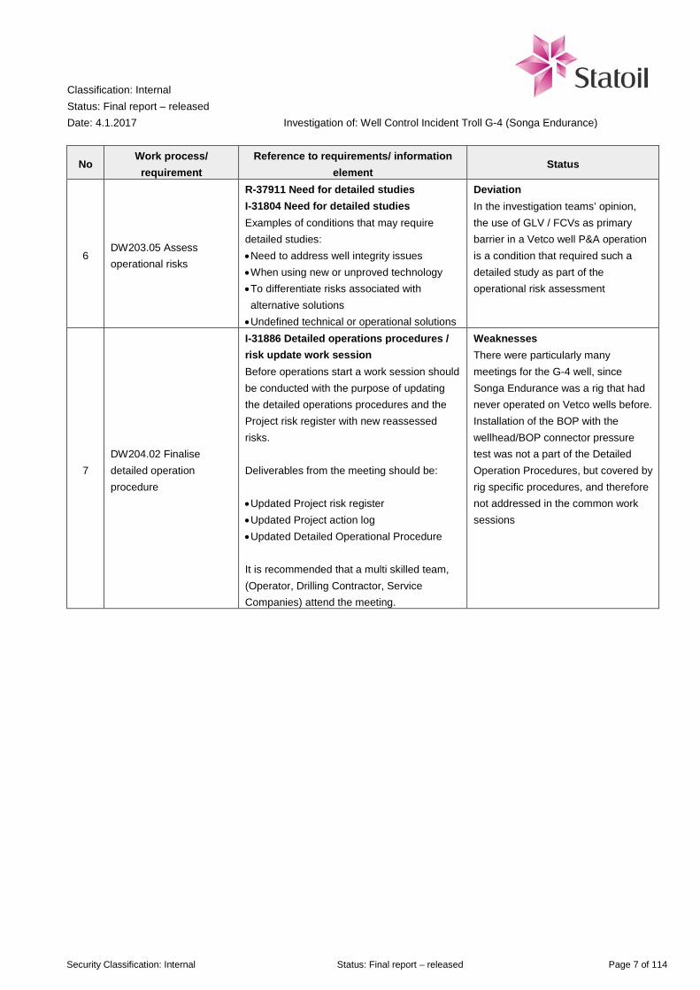
7 DW204.02 Finalise detailed operation procedure
I-31886 Detailed operations procedures / risk update work session Before operations start a work session should be conducted with the purpose of updating the detailed operations procedures and the Project risk register with new reassessed risks. Deliverables from the meeting should be: • Updated Project risk register • Updated Project action log • Updated Detailed Operational Procedure It is recommended that a multi skilled team, (Operator, Drilling Contractor, Service Companies) attend the meeting.
Weaknesses There were particularly many meetings for the G-4 well, since Songa Endurance was a rig that had never operated on Vetco wells before. Installation of the BOP with the wellhead/BOP connector pressure test was not a part of the Detailed Operation Procedures, but covered by rig specific procedures, and therefore not addressed in the common work sessions
Classification: Internal Status: Final report – released Date: 4.1.2017
Investigation of: Well Control Incident Troll G-4 (Songa Endurance)
Security Classification: Internal Status: Final report – released Page 8 of 114
No Work process/
requirement Reference to requirements/ information
element Status
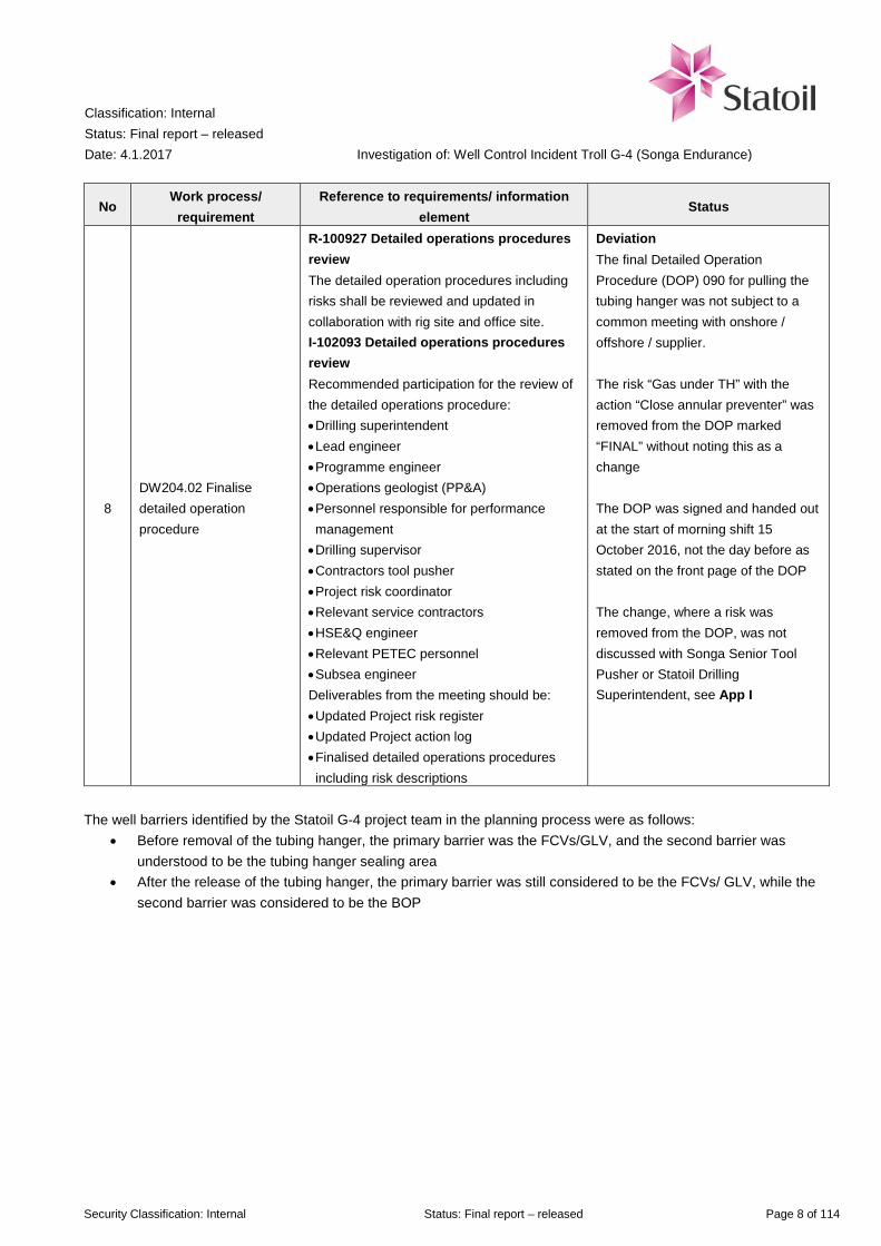
8 DW204.02 Finalise detailed operation procedure
R-100927 Detailed operations procedures review The detailed operation procedures including risks shall be reviewed and updated in collaboration with rig site and office site. I-102093 Detailed operations procedures review Recommended participation for the review of the detailed operations procedure: • Drilling superintendent • Lead engineer • Programme engineer • Operations geologist (PP&A) • Personnel responsible for performance management • Drilling supervisor • Contractors tool pusher • Project risk coordinator • Relevant service contractors • HSE&Q engineer • Relevant PETEC personnel • Subsea engineer Deliverables from the meeting should be: • Updated Project risk register • Updated Project action log • Finalised detailed operations procedures including risk descriptions
Deviation The final Detailed Operation Procedure (DOP) 090 for pulling the tubing hanger was not subject to a common meeting with onshore / offshore / supplier. The risk “Gas under TH” with the action “Close annular preventer” was removed from the DOP marked “FINAL” without noting this as a change The DOP was signed and handed out at the start of morning shift 15 October 2016, not the day before as stated on the front page of the DOP The change, where a risk was removed from the DOP, was not discussed with Songa Senior Tool Pusher or Statoil Drilling Superintendent, see App I
The well barriers identified by the Statoil G-4 project team in the planning process were as follows:
• Before removal of the tubing hanger, the primary barrier was the FCVs/GLV, and the second barrier was understood to be the tubing hanger sealing area
• After the release of the tubing hanger, the primary barrier was still considered to be the FCVs/ GLV, while the second barrier was considered to be the BOP

Classification: Internal Status: Final report – released Date: 4.1.2017
Investigation of: Well Control Incident Troll G-4 (Songa Endurance)
Security Classification: Internal Status: Final report – released Page 9 of 114
The relevant barriers that have been identified are given in the table below.
No Barrier element Reference to requirement /
performance standard Barrier status Causes
Before the well control incident 1 Establishing of project
team DW203.01 Weak barrier The project team did not
have sufficient competence and experience regarding the Vetco well type on G-4
2 Risk identification in detailed planning
DW203.05 Weak barrier The risk of applying a new well barrier not previously used in P&A of Vetco wells (FCV/GLV) was not treated with sufficient detail
3 Risk identification in execution
TR2385 B.3.2 item 6 (Ref /13/) The valve shall be documented to not shift position after it is put in closed position (being as a result of thermal or other erroneous operation through the pressure tubes)
Broken The FCVs and GLV were cycled from fully closed to fully open during a connection test between the BOP and the wellhead, and could also have cycled for other reasons
4 Well barrier requirement: Two independent barriers
TR3507 - 2. Well Integrity fundamentals “ A well shall be designed to have two defined independent well barriers without common barrier elements. The actual position and status of the barriers or barrier elements shall be known at all times. Scenarios with dependant or common barrier elements during construction, and other critical barrier failure scenarios, shall be covered in the Risk Evaluation
Broken Status of primary barrier was unknown before the incident, and plan did not account for failure in primary barrier. When the primary barrier was broken, the secondary barrier was subjected to high forces by the gas pressure. When the tubing hanger was unlocked from the wellhead, the secondary barrier was broken as the tubing hanger, tubing and drill string was lifted by the gas pressure
Well control incident

Classification: Internal Status: Final report – released Date: 4.1.2017
Investigation of: Well Control Incident Troll G-4 (Songa Endurance)
Security Classification: Internal Status: Final report – released Page 10 of 114
No Barrier element Reference to requirement /
performance standard Barrier status Causes
5 Red zone on drill floor Songa Offshore procedure Intact barrier Parts of the drill floor is defined as “red zone”. Unless documented in a risk analysis, the red zone is unmanned when equipment is in motion
6 Gas detection PS 3 in TR1055 (Ref /12/)
Intact barrier Gas detectors on main deck and on the drill floor detected gas, and gave automatic predefined actions according to Cause&Effect (Ref /7/)
7 Ignition source control PS 6 in TR1055 (Ref /12/)
Intact barrier Non-Ex proof equipment was automatically disconnected in areas where gas had been detected
8 PA announcement and general alarm
PS 13 in TR1055 (Ref /12/)
Intact barrier On confirmed gas detection (two or more gas detectors measuring above 20% LEL within the same fire area), automatic general alarm was sounded. The alarm alerted personnel to stop all work, and muster according to station bill
9 Escape, Evacuation and Rescue
PS 14 in TR1055 (Ref /12/)
Weak barrier The POB was not complete before 28 minutes after the incident. The requirement is within 12 minutes
10 Human Machine Interface & Alarm Management
PS 22 in TR1055 (Ref /12/)
Intact barrier The annular preventer was activated manually 19 seconds after water was detected on the rotary. The tool pusher was able to do this from a control panel in the driller’s cabin
Classification: Internal Status: Final report – released Date: 4.1.2017
Investigation of: Well Control Incident Troll G-4 (Songa Endurance)
Security Classification: Internal Status: Final report – released Page 11 of 114
No Barrier element Reference to requirement /
performance standard Barrier status Causes
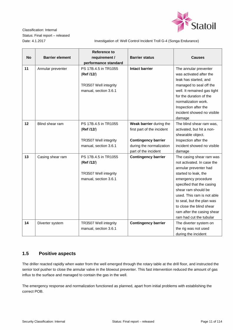
11 Annular preventer PS 17B.4.5 in TR1055 (Ref /12/) TR3507 Well integrity manual, section 3.6.1
Intact barrier
The annular preventer was activated after the leak has started, and managed to seal off the well. It remained gas tight for the duration of the normalization work. Inspection after the incident showed no visible damage
12 Blind shear ram PS 17B.4.5 in TR1055 (Ref /12/) TR3507 Well integrity manual, section 3.6.1
Weak barrier during the first part of the incident Contingency barrier during the normalization part of the incident
The blind shear ram was, activated, but hit a non-shearable object. Inspection after the incident showed no visible damage
13 Casing shear ram PS 17B.4.5 in TR1055 (Ref /12/) TR3507 Well integrity manual, section 3.6.1
Contingency barrier The casing shear ram was not activated. In case the annular preventer had started to leak, the emergency procedure specified that the casing shear ram should be used. This ram is not able to seal, but the plan was to close the blind shear ram after the casing shear ram had cut the tubular
14 Diverter system TR3507 Well integrity manual, section 3.6.1
Contingency barrier The diverter system on the rig was not used during the incident
1.5 Positive aspects
The driller reacted rapidly when water from the well emerged through the rotary table at the drill floor, and instructed the senior tool pusher to close the annular valve in the blowout preventer. This fast intervention reduced the amount of gas influx to the surface and managed to contain the gas in the well. The emergency response and normalization functioned as planned, apart from initial problems with establishing the correct POB.

Classification: Internal Status: Final report – released Date: 4.1.2017
Investigation of: Well Control Incident Troll G-4 (Songa Endurance)
Security Classification: Internal Status: Final report – released Page 12 of 114
1.6 Recommendations for learning
No Learning and
improvement needs Recommended actions Target group
1
Plan to improve change management and risk identification in drilling projects
1: Establish a project to go further in examining ways to improve the management of change and risk identification in drilling projects. The project should also do a deeper cause analysis regarding why there were shortcomings in this and other recent well control incidents
TPD D&W
2 Improved management of change
2A: Awareness of balance between team diversity and field specific competence when establishing new teams
TPD D&W
2B: Must elaborate on potential consequences, i.e. impact and risk, of changes that are made, compared to previous operations
TPD D&W
2C: Establish system for competence mapping of Engineers in D&W, include well integrity and control, and DISP request process in more detail
TPD D&W
2D: Establish clear criteria for the DOP change process, and responsibilities between onshore and offshore. Needs to be included in governing documentation
TPD D&W
3 Improved quality in planning and risk management
3A: Increase competence in preparation and facilitation of risk meetings
TPD D&W
3B: Identify and emphasize the well specific risks, highlight changes
TPD D&W
3C: Clarify expectations to participants in risk meetings / DOP meetings
TPD D&W
3D: Improve understanding of Vetco wellhead system by establishing a specific training program for relevant personnel
TPD D&W Troll Songa Offshore and other relevant suppliers In addition to Troll, other fields use vertical XT
3E: Make a WBS for the unlatching of tubing hanger sequence. TPD D&W
4 Better understanding of dispensation requests (DISP)
4: Inform project members about DISP process and the responsibilities of each individual role DISP related to well integrity shall always have a thorough risk assessment and shall be reviewed and supported by Manager D&W before sent to professional ladder for QA/QC Review ARIS-process for DISP, including supplier involvement.
TPD D&W DPN
5 Increase robustness of barriers
5A: Consider revision of TR2385 / GL3507 regarding use of valves that can be cycled as well barrier in P&A operations. Point out the specific risk when using cyclable valves as barriers in the GL3507
TPD D&W Well Technology

Classification: Internal Status: Final report – released Date: 4.1.2017
Investigation of: Well Control Incident Troll G-4 (Songa Endurance)
Security Classification: Internal Status: Final report – released Page 13 of 114
No Learning and
improvement needs Recommended actions Target group
5B: Recommend use of deep set plugs during P&A on VXT TPD D&W 5C: Increase understanding of the integrity of the barriers and which barriers are in place at any given time, including need for independence between different barriers Operational personnel need to be aware of the barriers in the different stages of operation, must be usable on the rig as an operational tool (WBS in DOP)
TPD D&W / Songa Offshore
6 Continuous learning
6A: Increase knowledge of gas reservoir in Troll where the large gas cap can have high consequence in case of influx
TPD D&W Troll/ Songa Offshore
6B: Inform D&W engineering and operational personnel about capabilities of BOP– need for robustness in well planning
TPD D&W Well Control Equipment Songa Offshore
6C: Establish an industry project to review BOP robustness and limitations
TPD
6D: Experience transfer on the consequence of cycling a valve used as a well barrier, and how they can be unintentionally cycled
TPD D&W DPN Songa Offshore
6E: Inform about difference between “lowest pressure needed to operate” and “recommended minimum pressure used to operate”
TPD D&W DPN
6F: Experience sharing with IOGP, Drilling managers’ forum, NOG, Rig owners’ association, Statoil’s Troll partners
TPD D&W
6G: More focus on POB control and expand the training and drills with more realistic scenarios
Songa Offshore

Classification: Internal Status: Final report – released Date: 4.1.2017
Investigation of: Well Control Incident Troll G-4 (Songa Endurance)
Security Classification: Internal Status: Final report – released Page 14 of 114
2 Investigation mandate and investigation execution
2.1 Mandate

Classification: Internal Status: Final report – released Date: 4.1.2017
Investigation of: Well Control Incident Troll G-4 (Songa Endurance)
Security Classification: Internal Status: Final report – released Page 15 of 114
2.1.1 Changes to the mandate
On 25 October it was clarified by e-mail with commissioning entity that the investigation should include the normalization work up to the point of two barriers, without loss to formation. The commissioning entity requested a second, limited hearing process. This delayed the issuing of the final report from the planned date 15 December 2016. During this process, it was also decided to have Margareth Øvrum, Executive Vice President of TPD as commissioning entity for the investigation. The investigation was also to be carried out at commissioning level 1.
2.2 Investigation work
The decision to perform an investigation was made on 18 October 2016, and the investigation team was established on 20 October 2016. It was then decided to have a joint Statoil and Songa investigation team. The investigation work has consisted of collection and review of documents, interviews, meetings, and relevant technical analyses and calculations. It was decided that a visit to the installation Songa Endurance was not required. A total of 21 interviews and meetings were conducted during the investigation, with a total of 34 Statoil, Songa Endurance and supplier employees. An overview of the interviewees is included as App A. The investigation work has been performed in accordance with Statoil’s work process for investigations as described in ARIS INV01. The investigation team requested a study on gas leak rates, dispersion and explosion risk, see App K. This was carried out by Ole Kristian Sommersel and Hanne Gøril Thomassen in Statoil’s department for Safety Technology (Research & Technology). The program used for the analysis cannot simulate a water filled riser with a given hydrostatic column. The rate calculations are therefore based on the assumption that the water is pushed out like a plug, with atmospheric counter pressure. This gives a conservative value for the rate. At a given point, the annular preventer was closed, which gradually reduced the leak rate. Both the reduction caused by the annular preventer closing and the increase due to a falling counter pressure happened simultaneously. The tools used are not able to calculate this, as they are designed for gas spread analysis, not process conditions in pipes. The investigation team was assisted by the Troll environmental coordinator to consider the potential consequences of a subsea blowout from well G-4, see section 5.3.3. One member of the investigation team, Knut Halvorsen, was involved in the approval of a dispensation request (DISP) in relation to the use of gas lift and flow control valves as well barriers, see section 3.3.5. The findings presented in this report are supported by a united investigation team.
Classification: Internal Status: Final report – released Date: 4.1.2017
Investigation of: Well Control Incident Troll G-4 (Songa Endurance)
Security Classification: Internal Status: Final report – released Page 16 of 114
3 Background information
3.1 Unit / site
3.1.1 Songa Endurance
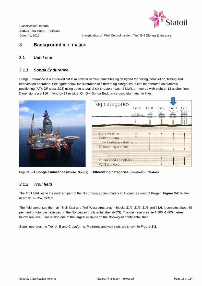
Songa Endurance is a so-called cat D mid-water semi-submersible rig designed for drilling, completion, testing and intervention operation. See figure below for illustration of different rig categories. It can be operated on dynamic positioning (ATA DP class 2&3) using up to a total of six thrusters (each 4 MW), or moored with eight or 12 anchor lines. Dimensions are 116 m long by 97 m wide. On G-4 Songa Endurance used eight anchor lines.
Figure 3-1 Songa Endurance (Photo: Songa) Different rig categories (Illustration: Statoil)
3.1.2 Troll field
The Troll field lies in the northern part of the North Sea, approximately 70 kilometres west of Bergen, Figure 3-2. Water depth 313 – 352 meters. The field comprises the main Troll East and Troll West structures in blocks 31/2, 31/3, 31/5 and 31/6. It contains about 40 per cent of total gas reserves on the Norwegian continental shelf (NCS). The gas reservoirs lie 1 500 -1 600 metres below sea level. Troll is also one of the largest oil fields on the Norwegian continental shelf. Statoil operates the Troll A, B and C platforms. Platforms and well slots are shown in Figure 3-3.

Classification: Internal Status: Final report – released Date: 4.1.2017
Investigation of: Well Control Incident Troll G-4 (Songa Endurance)
Security Classification: Internal Status: Final report – released Page 17 of 114
Figure 3-2 Location of the Troll field (Illustration: Statoil)
Figure 3-3 Templates and oil, gas and water line view Troll field. G-4 indicated by blue arrow (Illustration: Statoil, Ref /5/)
Classification: Internal Status: Final report – released Date: 4.1.2017
Investigation of: Well Control Incident Troll G-4 (Songa Endurance)
Security Classification: Internal Status: Final report – released Page 18 of 114
As of mid-2015 Troll had the number and type of well slots as shown in Table 3-1.
Table 3-1 Well slots on Troll as of mid-2015 (Ref /2/)
Vendor Satellite Structure Template Structure No. of wells Christmas tree (XT)
System Vetco D - H - 27 Vertical (VXT) Aker Subsea - I – Y 89 Horizontal (HXT) FMC Z1 & Z2 O2 8 Horizontal (HXT)
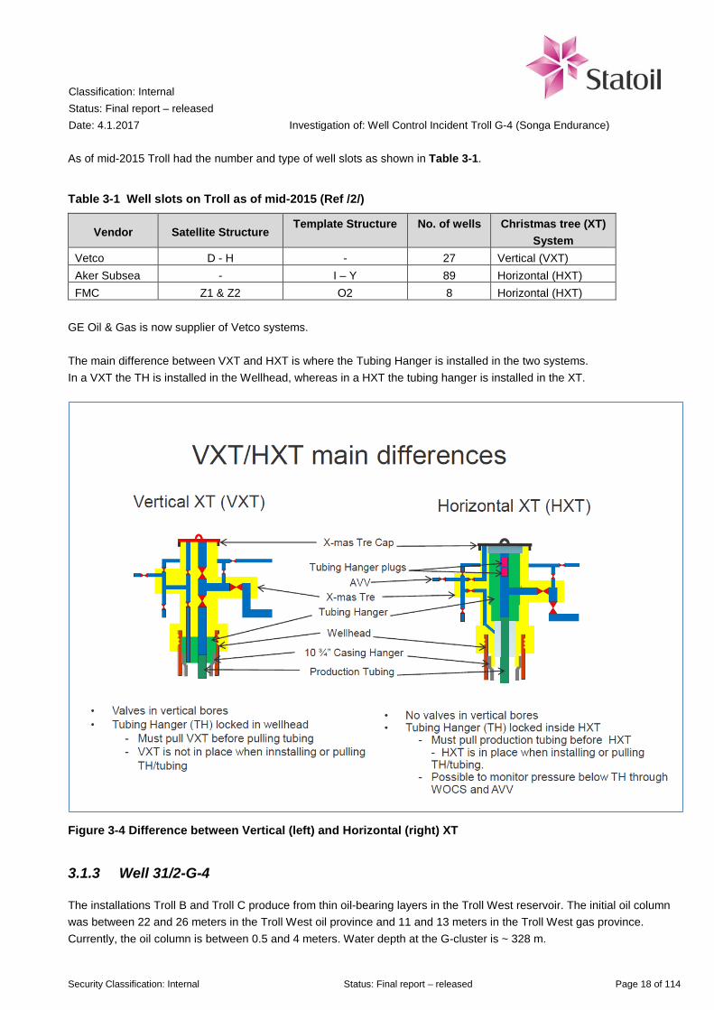
GE Oil & Gas is now supplier of Vetco systems. The main difference between VXT and HXT is where the Tubing Hanger is installed in the two systems. In a VXT the TH is installed in the Wellhead, whereas in a HXT the tubing hanger is installed in the XT.
Figure 3-4 Difference between Vertical (left) and Horizontal (right) XT
3.1.3 Well 31/2-G-4
The installations Troll B and Troll C produce from thin oil-bearing layers in the Troll West reservoir. The initial oil column was between 22 and 26 meters in the Troll West oil province and 11 and 13 meters in the Troll West gas province. Currently, the oil column is between 0.5 and 4 meters. Water depth at the G-cluster is ~ 328 m.

Classification: Internal Status: Final report – released Date: 4.1.2017
Investigation of: Well Control Incident Troll G-4 (Songa Endurance)
Security Classification: Internal Status: Final report – released Page 19 of 114
All of the more than 110 production wells drilled in Troll Oil are horizontal wells. Many of the wells are multi-lateral wells, which have two, three or four horizontal sections that radiate out from a conjunctive point in the reservoir. Well 31/2-G-4 is a satellite well connected to G-manifold through flow line and Integrated Service Umbilical (ISU). G-4 has a Vertical XT (VXT), as shown in Table 3-1. G-4 is connected to Troll B. G-4 H/AH was first drilled and completed by the drilling rig Polar Pioneer in 1994. This well was permanently plugged in 2011 by West Venture, and then side tracked to BY1H/BY2H by Songa Trym the same year. These wellbores were completed by West Venture in January 2012. Due to high water cut in BY1H/BY2H, decision had been made to permanently plug the BY wellbores to facilitate for a side track and drilling of a new multilateral well; G-4 CY1H/CY2H/CY3H.
3.2 Organisation
The organisation of Statoil’s Songa Endurance team and interfaces is shown in Figure 3-5. Note: The arrows are not intended to show communication lines. Other organisation charts are given in App E.
Figure 3-5 Statoil organization for Statoil’s Songa Endurance D&W project (Ref /4/)
Songa Offshore Ltd
Planning Department Mobile Drilling Units Troll
Planner

Classification: Internal Status: Final report – released Date: 4.1.2017
Investigation of: Well Control Incident Troll G-4 (Songa Endurance)
Security Classification: Internal Status: Final report – released Page 20 of 114
3.3 Technical/operational descriptions
3.3.1 Plug & Abandonment
Plug & Abandonment (P&A) of a well means securing a well by installation of well barriers, i.e. barriers against flow from the well. Barriers may consist of cement plugs, mechanical plugs or a combination thereof. Verification of the integrity, quality, suitability, durability and robustness of the barrier is the basis for a successful P&A. In 2014 an initiative was taken to improve efficiency in Troll P&A operations. One of the proposed measures was, instead of using deep set mechanical plugs as primary barrier, to accept flow control valves (FCV) and gas lift valves (GLV) as barriers during P&A operations. The issue was discussed by the Well Integrity Specialists and support was given for horizontal XT where it is possible to monitor pressure in annulus and tubing (below the tubing hanger), under the condition that a set of prerequisites were fulfilled, such as pressure testing and short time use (some days, not weeks) (Ref/36/). The support did not include Vetco wells (such as well G-4) with their vertical XT that did not enable monitoring pressure under the tubing hanger. “Troll Main Activity Program for Plug and Abandonment and prepare side track” (Ref /3/) was established in 2015 to support concept selection and act as reference for the well specific activity programs. The purpose of the program is stated to standardize and improve the P&A and slot recovery operations on Troll. The distinctiveness of two of the different wellhead systems (VXT versus HXT; Vetco / Aker) is described in this document, but FMC wells are not covered. In the section concerning Vetco wells, the Main Activity Program P&A notes the following (emphasis added by the investigation team):
3.3.2 Flow Control and Gas Lift Valves
The two hydraulically operated Flow Control Valves (FCVs) and a single Gas Lift Valve, all delivered by Baker Hughes, were installed during the completion phase of G-4 BY1H/BY2H in 2012. The main purpose of the two HCM-A installed as FCVs is to control flow from the two horizontal well paths in G-4. The purpose of the HCM-A installed as a GLV is to adjust gas lift during production. Normal control of the valve during production of the well is from the Subsea Control Module (SCM), which is placed on the XT. The Control Room Operator on Troll B platform uses the control system to operate the SCM and thereby the FCV/GLVs. The valves are operated by means of hydraulic pressure through a ¼ inch control line which on vertical XTs extends from the XT through check valves (“poppets”) in the TH down through the production packer to the GLV and FCVs located in the gas cap of the reservoir and in the oil bearing zone in the reservoir, respectively.
Classification: Internal Status: Final report – released Date: 4.1.2017
Investigation of: Well Control Incident Troll G-4 (Songa Endurance)
Security Classification: Internal Status: Final report – released Page 21 of 114
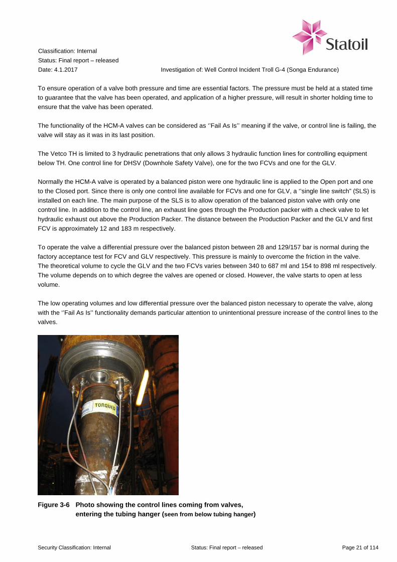
To ensure operation of a valve both pressure and time are essential factors. The pressure must be held at a stated time to guarantee that the valve has been operated, and application of a higher pressure, will result in shorter holding time to ensure that the valve has been operated. The functionality of the HCM-A valves can be considered as ‘’Fail As Is’’ meaning if the valve, or control line is failing, the valve will stay as it was in its last position. The Vetco TH is limited to 3 hydraulic penetrations that only allows 3 hydraulic function lines for controlling equipment below TH. One control line for DHSV (Downhole Safety Valve), one for the two FCVs and one for the GLV. Normally the HCM-A valve is operated by a balanced piston were one hydraulic line is applied to the Open port and one to the Closed port. Since there is only one control line available for FCVs and one for GLV, a ‘’single line switch” (SLS) is installed on each line. The main purpose of the SLS is to allow operation of the balanced piston valve with only one control line. In addition to the control line, an exhaust line goes through the Production packer with a check valve to let hydraulic exhaust out above the Production Packer. The distance between the Production Packer and the GLV and first FCV is approximately 12 and 183 m respectively. To operate the valve a differential pressure over the balanced piston between 28 and 129/157 bar is normal during the factory acceptance test for FCV and GLV respectively. This pressure is mainly to overcome the friction in the valve. The theoretical volume to cycle the GLV and the two FCVs varies between 340 to 687 ml and 154 to 898 ml respectively. The volume depends on to which degree the valves are opened or closed. However, the valve starts to open at less volume. The low operating volumes and low differential pressure over the balanced piston necessary to operate the valve, along with the ‘’Fail As Is’’ functionality demands particular attention to unintentional pressure increase of the control lines to the valves.
Figure 3-6 Photo showing the control lines coming from valves, entering the tubing hanger (seen from below tubing hanger)

Classification: Internal Status: Final report – released Date: 4.1.2017
Investigation of: Well Control Incident Troll G-4 (Songa Endurance)
Security Classification: Internal Status: Final report – released Page 22 of 114
Figure 3-7 Control line and exhaust connection for the FCVs (left) and GLV (right) (Source: Baker Hughes)
Further details and drawings on the HCM-A valve is shown in App G.
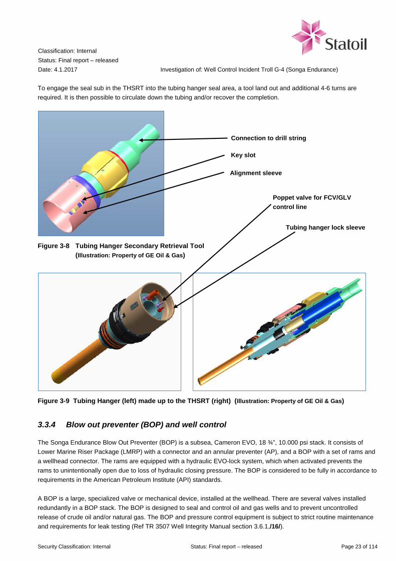
3.3.3 Tubing Hanger Secondary Retrieval Tool (THSRT)
The tubing hanger secondary retrieval tool (THSRT) is a mechanically operated tool designed to retrieve the tubing hanger (TH) and completion string. It is a simpler tool compared to the hydraulic THRT used to run and land the completion. The tool has an alignment sleeve with a key slot, which engages on to the tubing hanger key. When the THSRT is fully landed on the tubing hanger, right hand rotation is applied to the tool. A pin in the tool is sheared and the tool is made up to the hanger with 2-4 turns. Then a straight pull up will move the tubing hanger lock sleeve. Maximum pull is 7.5 cm in order to maintain seal in the tubing hanger. This will unlock the tubing hanger from the wellhead by retracting the locking dogs, but with a limited pull, the tubing hanger will not be lifted loose. The seal between tubing hanger and wellhead will therefore remain intact. An estimated 18 tons over pull is required to pull the TH locking sleeve up into unlock position. At this stage the TH is unlocked but there is no seal between the TH and THSRT. It is however possible to pull the completion in this position.
Classification: Internal Status: Final report – released Date: 4.1.2017
Investigation of: Well Control Incident Troll G-4 (Songa Endurance)
Security Classification: Internal Status: Final report – released Page 23 of 114
To engage the seal sub in the THSRT into the tubing hanger seal area, a tool land out and additional 4-6 turns are required. It is then possible to circulate down the tubing and/or recover the completion.
Figure 3-8 Tubing Hanger Secondary Retrieval Tool (Illustration: Property of GE Oil & Gas)
Figure 3-9 Tubing Hanger (left) made up to the THSRT (right) (Illustration: Property of GE Oil & Gas)
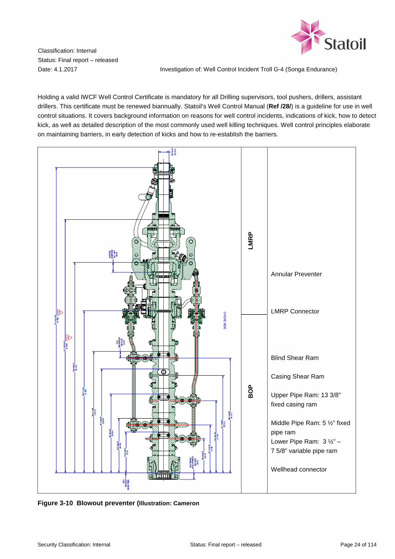
3.3.4 Blow out preventer (BOP) and well control
The Songa Endurance Blow Out Preventer (BOP) is a subsea, Cameron EVO, 18 ¾”, 10.000 psi stack. It consists of Lower Marine Riser Package (LMRP) with a connector and an annular preventer (AP), and a BOP with a set of rams and a wellhead connector. The rams are equipped with a hydraulic EVO-lock system, which when activated prevents the rams to unintentionally open due to loss of hydraulic closing pressure. The BOP is considered to be fully in accordance to requirements in the American Petroleum Institute (API) standards. A BOP is a large, specialized valve or mechanical device, installed at the wellhead. There are several valves installed redundantly in a BOP stack. The BOP is designed to seal and control oil and gas wells and to prevent uncontrolled release of crude oil and/or natural gas. The BOP and pressure control equipment is subject to strict routine maintenance and requirements for leak testing (Ref TR 3507 Well Integrity Manual section 3.6.1,/16/).
Alignment sleeve
Connection to drill string
Key slot
Tubing hanger lock sleeve
Poppet valve for FCV/GLV control line
Classification: Internal Status: Final report – released Date: 4.1.2017
Investigation of: Well Control Incident Troll G-4 (Songa Endurance)
Security Classification: Internal Status: Final report – released Page 24 of 114
Holding a valid IWCF Well Control Certificate is mandatory for all Drilling supervisors, tool pushers, drillers, assistant drillers. This certificate must be renewed biannually. Statoil’s Well Control Manual (Ref /28/) is a guideline for use in well control situations. It covers background information on reasons for well control incidents, indications of kick, how to detect kick, as well as detailed description of the most commonly used well killing techniques. Well control principles elaborate on maintaining barriers, in early detection of kicks and how to re-establish the barriers.
B
OP
L
MR
P
Annular Preventer LMRP Connector Blind Shear Ram Casing Shear Ram Upper Pipe Ram: 13 3/8” fixed casing ram Middle Pipe Ram: 5 ½” fixed pipe ram Lower Pipe Ram: 3 ½” – 7 5/8” variable pipe ram Wellhead connector
Figure 3-10 Blowout preventer (Illustration: Cameron

Classification: Internal Status: Final report – released Date: 4.1.2017
Investigation of: Well Control Incident Troll G-4 (Songa Endurance)
Security Classification: Internal Status: Final report – released Page 25 of 114
Table 3-2 Description of the items in the Blowout preventer
Item Function Annular preventer Flexible elastomer designed to close on any diameter or on itself.
It is possible to move the drill string up or down through a annular preventer that is closed with reduced pressure. This operation is called stripping
Lower Marine Riser Package connector
Disconnection point if an emergency release is needed. Disconnect point is between Annular and Blind Shear Ram
Blind shear ram Designed to cut defined sizes, weights and grades of drill pipe/tubing and make a tight seal against fluids
Casing shear ram Designed to cut heavier objects such as various defined sizes, weights and grades of casing
Upper pipe ram A fixed ram designed to seal against a 13 3/8” casing Middle pipe ram A fixed ram designed to seal against a 5 ½” drill pipe or tubing Lower pipe ram A variable ram with interchangeable inserts (must be done topside)
designed to seal against 3 ½” to 7 5/8” casing Wellhead connection Connecting the BOP to the wellhead
Cameron, the manufacturer of the BOP on Songa Endurance, confirm that the topic of flow testing is not covered by the API requirements or any other applicable standards for such equipment. However, Cameron state that flowing condition should not have any effect on the closing operation of the annular BOP. A report following the 2010 Macondo well incident was prepared for the United States Government Bureau of Safety and Environmental Enforcement (BSSE) (Ref /31/). The report concluded that all previous studies and tests had been performed under non-flowing conditions.
3.3.5 Dispensations for actual operation at G-4
Three dispensation requests (DISP) for deviation from Statoil’s requirements were made for the operation at G-4. The DISPs are given in Table 3-3. No exemptions from authority requirements were made.

Classification: Internal Status: Final report – released Date: 4.1.2017
Investigation of: Well Control Incident Troll G-4 (Songa Endurance)
Security Classification: Internal Status: Final report – released Page 26 of 114
Table 3-3 Dispensation requests (DISP) for operation on G-4
DISP Description Relevance 145458 Utilizing GLV as a barrier element on
well 31/2-G-4 BY1H/BY2H, dispensation from TR3507 Well Integrity Manual offshore operations (Ref /16/) The dispensation was a request to use the GLV as a barrier element even though the annulus behind the GLV would be gas filled and thus not according to requirement in TR2385 (Ref /13/) (filled with liquid) Status: Approved
The dispensation text mentions that instead of setting a deep set tubing plug the planning team wanted to plan for closing FCVs and GLV, and use these as primary barrier elements Additional testing is performed on the valves delivered for Vetco wells (Vertical XT) with pressure testing each valve in both directions. Valves are rated to 344 bar in both directions. (See mail from vendor attached to DISP: RE: G-4 BY1H/BY2H - Use GLV and FCV as barrier elements) In an attached list of items from the risk register, ID 3.0-05 states the hazard “Unable to operate/close GLV” with contingency “Install deep set tubing plug”, and ID 3.0-07 “Unable to cycle FCVs” with contingency “Need to run deep set plug above production packer”. The risk of unintentional cycling of the valves was not mentioned.
145499 Transport tubulars in slings without protectors on Troll 31/2-G-4 BY1H/BY2H P&A Status: Approved
Not relevant for the well integrity incident
145922 Pulling VXT with one barrier against reservoir pressure - 31/2 G-4 BY1H/BY2H P&A, dispensation from TR3507 Well Integrity Manual offshore operations (Ref /16/) The reason for the dispensation request is that on Vetco wellhead system it is not possible to have two complete barriers against reservoir pressure while pulling the XT Status: Approved
The dispensation text mentions that “the control lines for operating the GLV and FCV's goes through the tubing hanger to connectors that the VXT fit into. In these connectors there are "Poppets" (Check valves that will close when the VXT is removed, and stop CL fluid from leaking into sea) but these are not qualified for being a barrier even though they are tested to 689 Bar/10 000PSI in workshop. The poppets can't be tested since they only stop fluid from below. GE Oil & Gas Vetco Gray have no experience with leaking poppet valves.”
3.3.6 Risk register for operation at G-4
The project maintains a risk register for each of the three different phases: concept selection, detailed planning and execution. The risk registers show an increasing level of detail, with number of identified risks 23 in concept selection (5 during operation relevant for this incident), 185 in detailed planning (24 during relevant operation) and 313 during execution (67 in relevant operation). Risk for unintentional cycling of the GLV and FCVs is not mentioned in any phases of the risk register.

Classification: Internal Status: Final report – released Date: 4.1.2017
Investigation of: Well Control Incident Troll G-4 (Songa Endurance)
Security Classification: Internal Status: Final report – released Page 27 of 114
4 Sequence of events
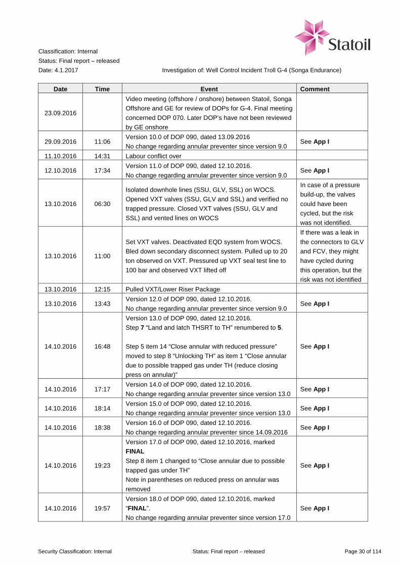
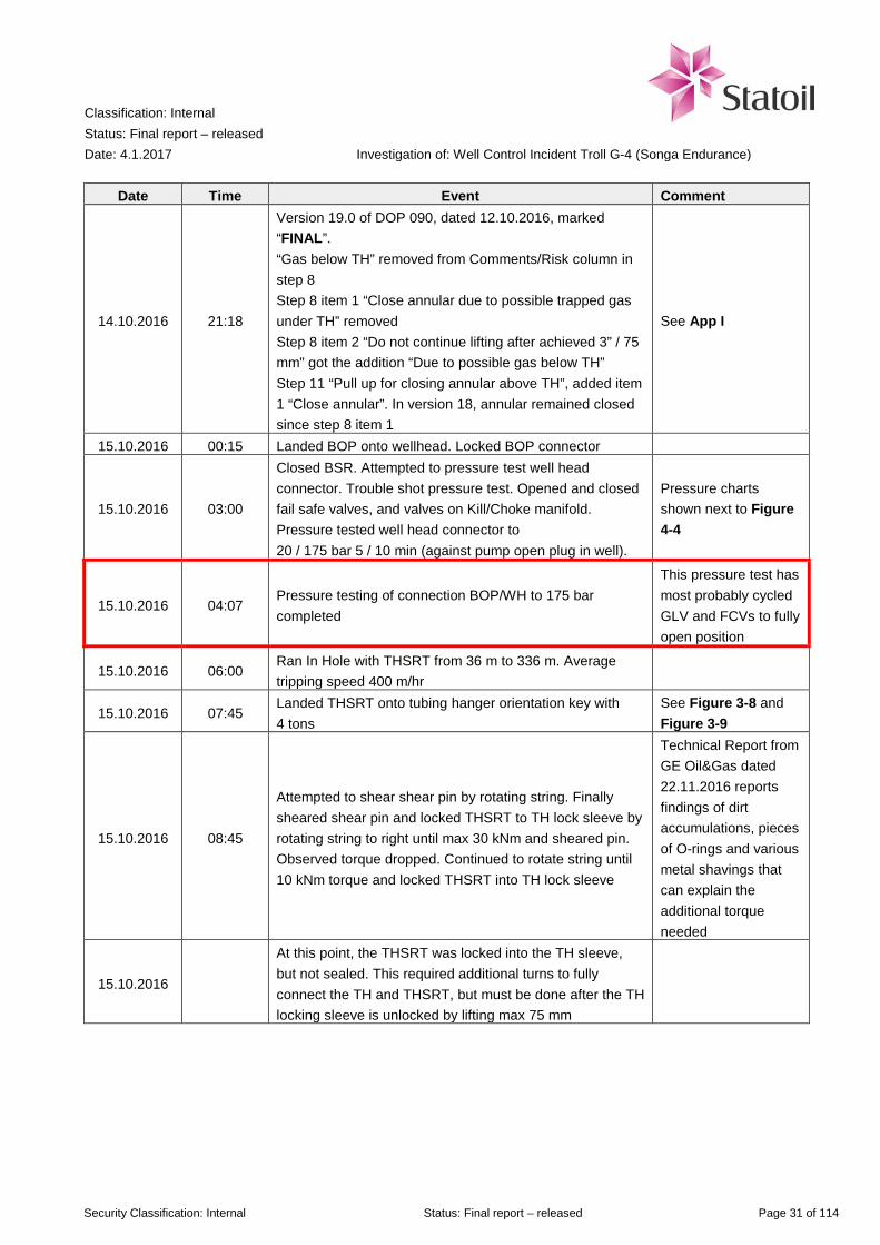
The sequence of events before the plug and abandonment operation started on well G-4 is given in Table 4-1. The events during the operation that led to the well control incident is described in section 4.2. Immediate emergency response is covered in section 4.3, while the normalization work, lasting 13 days, is described in section 4.4. Focus is on events that had significance for the occurrence of the incident and consequences. Other activities are only included to the extent necessary to understand the sequence of events.
4.1 Events before the plug & abandonment operation on G-4
Table 4-1 Sequence of events
Date Time Event Comment
22.03.2012 Final well report - top completion 31/2-G-4 BY1H/BY2H signed
This is the G-4 well that Songa Endurance planned to plug and drill new sidetrack on
31.07.2013 Attempted to pressure test tubing/HCM-A's/GLV without success on well 31/2-G-3 AY3H. This was the first time Troll planned to use GLV/FCV as barrier for VXT change
This is a different operation than a P&A
12.06.2014 Troll P&A Improvement project initiated: Scope 4: Evaluate to use FCV & GLV as barriers during P&A (and completion): OK Closed 29.09.2015
This was only approved for horizontal XT (Aker)
15.11.2014 Well 31/2-F-1 BY1H Permanent P&A. Troll planned to use GLV/FCV as barrier for a P&A operation (identical to G-4 P&A)
FCV was leaking, used deep set plug instead
30.03.2015 Detailed Drilling Instruction DDI 090 "Pull TH & upper completion using THSRT" as done for West Venture operation on well 31/2 D-5, Ref /10/.
This document was used as basis for the Detailed Operation Procedures for Songa Endurance on G-4
27.05.2015 Troll Main Activity Program – Plug and Abandonment and prepare sidetrack was approved.
Was not referenced in G-4 planning
18.08.2015 Changed VXT on well 31/2-F-1. Used FCV and GLV as temporary barrier elements during Work Over operation.
Referenced in G-4 planning, but different operation than a P&A.
24.08.2015 Delivery of Songa Endurance from Daewoo (DSME) to Songa Offshore
17.12.2015 PSA issue Acknowledgement of Compliance declaration to Songa Endurance. The same day Statoil received consent to use Songa Endurance on Troll
29.01.2016 Concept risk for well G-4 does not mention use of FCV as barrier elements
11.02.2016 02:15 Started to clean the well 31/2-N-23 AY1H First operation for Songa Endurance

Classification: Internal Status: Final report – released Date: 4.1.2017
Investigation of: Well Control Incident Troll G-4 (Songa Endurance)
Security Classification: Internal Status: Final report – released Page 28 of 114
Date Time Event Comment
25.05.2016 18:15 Moved rig from well N-23 to N-22. Planned operation: Permanent P&A on an Aker well with horizontal XT
Second operation for Songa Endurance
28.06.2016 G-4 Risk meeting - Detailed Planning P&A, Drilling and Completion
GE Oil & Gas not present
30.06.2016 DISP application 145458 for use of GLV as barrier element was initiated
See section 3.3.5
08.07.2016 G-4 plug and abandonment-program signed
26.07.2016 DISP 145458 for use of GLV as barrier element was approved
See section 3.3.5
29.07.2016 G-4 slot 24 handed from Troll B (GLV 100% og FCV 0 %) to Drilling & Well
04.08.2016 DISP application 145922 for pulling VXT without two barriers against reservoir was initiated
See section 3.3.5
24.08.2016 G-4 Risk register - Execute Operation P&A, Drilling and Completion – draft
25.08.2016
Full day meeting between Statoil, Songa Offshore, Altus and GE for review of DOPs for G-4. The meetings were more extensive than usual on request by Songa Offshore Rig Manager for Songa Endurance, since he wanted more Vetco competence in the new rig project. This was mostly regarding handling of Vetco equipment with a new rig, not well specific details. This was agreed upon by Statoil’s Drilling Superintendent
GE Oil & Gas was asked to deliver Vetco experience in these meetings. Statoil engineers with detailed knowledge of FCVs and their operation, and GE Oil & Gas offshore engineers were not present in the meetings
01.09.2016 DISP 145922 for pulling VXT without two barriers against reservoir was approved
See section 3.3.5
14.09.2016 13:37
Version 9.0 of DOP 090, dated 13.09.2016. Risks: Gas below TH, “Close Annular preventer with reduced pressure” in step 7 – item 14. “Annular to remain closed due to possible trapped gas under TH” in step 8 – item 1
See App I
14.09.2016 23:25 Songa Endurance arrived Troll G-4
15.09.2016 09:33 Status all P&A DOPs: updated: DOP090 80%. DOP meeting onshore. OK
DOP 090 was ready to be sent offshore for final update. Update from 80% to 100% is meant to be minor operational adjustments
16.09.2016 11:00 Anchor operations on G-4
16.09.2016 Video meeting between Statoil, Songa Offshore and GE for review of DOPs for G-4

Classification: Internal Status: Final report – released Date: 4.1.2017
Investigation of: Well Control Incident Troll G-4 (Songa Endurance)
Security Classification: Internal Status: Final report – released Page 29 of 114
Date Time Event Comment
20.09.2016 Video meeting between Statoil, Songa Offshore and GE for review of DOPs for G-4
20.09.2016 06:45 Pressure tested GLV control line and FCV control line to 345 bar for 10 min, bleed off pressure for 20 min
Test of integrity of the control lines
20.09.2016 11:30 Cycled GLV and FCV
Valves were cycled from the rig by valve supplier Baker Hughes
20.09.2016 13:45 Killed well by bullheading 107 m3 seawater Used Work over riser
20.09.2016 15:30 Cycled GLV / FCV to closed position and pressure tested completion string to 20/190 bar for 5/10 min
GLV and FCVs were now verified as primary barrier elements
20.09.2016 16:30 Reconnected control lines to GLV/FCVs to WOCS
20.09.2016 21:30 Cut tubing at 1277 m. Good indications of cut observed. Nothing seen on fluid levels
The investigation team assumes control lines to GLV / FCVs are intact and not cut, based on information about the tool used to cut the tubing
21.09.2016 04:00 Set plug according to procedure. Mid element at 391 m. Shallow set tubing plug was pressure tested to 190 bar (Pinned to 275 bar)
Shallow set plug
21.09.2016
Topped up annulus with SW. Closed WL BOP and pressure tested annulus plug to 20/175 bar for 5/10 min. Tubing hanger annulus plug run and pressure tested to 175 Bar (Pinned to 250 Bar)
Well filled with liquid
21.09.2016 07:00
Labour conflict. Wait for discussion on forward operation Statoil was obligated to stop the operation due to the labour conflict since the rig had two barriers in place and the next planned operation was to remove the XT Emergency Quick Disconnect Package and Work Over Riser were pulled. Lower Riser Package was left on the VXT as an additional barrier
Statoil Drilling Superintendent asked for pressure testing every possible leak points on the VXT. VXT valves were tested. GE Oil&Gas representative recommended not to test the "control line exit blocks" due to the fact that if there was a leak, the control line would be exposed for the test pressure and the GLV and/or the FCV's could cycle
21.09.2016 21:15 Moved rig 50 m to safe zone
Classification: Internal Status: Final report – released Date: 4.1.2017
Investigation of: Well Control Incident Troll G-4 (Songa Endurance)
Security Classification: Internal Status: Final report – released Page 30 of 114
Date Time Event Comment
23.09.2016
Video meeting (offshore / onshore) between Statoil, Songa Offshore and GE for review of DOPs for G-4. Final meeting concerned DOP 070. Later DOP’s have not been reviewed by GE onshore
29.09.2016 11:06 Version 10.0 of DOP 090, dated 13.09.2016 No change regarding annular preventer since version 9.0
See App I
11.10.2016 14:31 Labour conflict over
12.10.2016 17:34 Version 11.0 of DOP 090, dated 12.10.2016. No change regarding annular preventer since version 9.0
See App I
13.10.2016 06:30
Isolated downhole lines (SSU, GLV, SSL) on WOCS. Opened VXT valves (SSU, GLV and SSL) and verified no trapped pressure. Closed VXT valves (SSU, GLV and SSL) and vented lines on WOCS
In case of a pressure build-up, the valves could have been cycled, but the risk was not identified.
13.10.2016 11:00
Set VXT valves. Deactivated EQD system from WOCS. Bled down secondary disconnect system. Pulled up to 20 ton observed on VXT. Pressured up VXT seal test line to 100 bar and observed VXT lifted off
If there was a leak in the connectors to GLV and FCV, they might have cycled during this operation, but the risk was not identified
13.10.2016 12:15 Pulled VXT/Lower Riser Package
13.10.2016 13:43 Version 12.0 of DOP 090, dated 12.10.2016. No change regarding annular preventer since version 9.0
See App I
14.10.2016 16:48
Version 13.0 of DOP 090, dated 12.10.2016. Step 7 “Land and latch THSRT to TH” renumbered to 5. Step 5 item 14 “Close annular with reduced pressure” moved to step 8 “Unlocking TH” as item 1 “Close annular due to possible trapped gas under TH (reduce closing press on annular)”
See App I
14.10.2016 17:17 Version 14.0 of DOP 090, dated 12.10.2016. No change regarding annular preventer since version 13.0
See App I
14.10.2016 18:14 Version 15.0 of DOP 090, dated 12.10.2016. No change regarding annular preventer since version 13.0
See App I
14.10.2016 18:38 Version 16.0 of DOP 090, dated 12.10.2016. No change regarding annular preventer since 14.09.2016
See App I
14.10.2016 19:23
Version 17.0 of DOP 090, dated 12.10.2016, marked FINAL Step 8 item 1 changed to “Close annular due to possible trapped gas under TH” Note in parentheses on reduced press on annular was removed
See App I
14.10.2016 19:57 Version 18.0 of DOP 090, dated 12.10.2016, marked “FINAL”. No change regarding annular preventer since version 17.0
See App I
Classification: Internal Status: Final report – released Date: 4.1.2017
Investigation of: Well Control Incident Troll G-4 (Songa Endurance)
Security Classification: Internal Status: Final report – released Page 31 of 114
Date Time Event Comment
14.10.2016 21:18
Version 19.0 of DOP 090, dated 12.10.2016, marked “FINAL”. “Gas below TH” removed from Comments/Risk column in step 8 Step 8 item 1 “Close annular due to possible trapped gas under TH” removed Step 8 item 2 “Do not continue lifting after achieved 3” / 75 mm” got the addition “Due to possible gas below TH” Step 11 “Pull up for closing annular above TH”, added item 1 “Close annular”. In version 18, annular remained closed since step 8 item 1
See App I
15.10.2016 00:15 Landed BOP onto wellhead. Locked BOP connector
15.10.2016 03:00
Closed BSR. Attempted to pressure test well head connector. Trouble shot pressure test. Opened and closed fail safe valves, and valves on Kill/Choke manifold. Pressure tested well head connector to 20 / 175 bar 5 / 10 min (against pump open plug in well).
Pressure charts shown next to Figure 4-4
15.10.2016 04:07 Pressure testing of connection BOP/WH to 175 bar completed
This pressure test has most probably cycled GLV and FCVs to fully open position
15.10.2016 06:00 Ran In Hole with THSRT from 36 m to 336 m. Average tripping speed 400 m/hr
15.10.2016 07:45 Landed THSRT onto tubing hanger orientation key with 4 tons
See Figure 3-8 and Figure 3-9
15.10.2016 08:45
Attempted to shear shear pin by rotating string. Finally sheared shear pin and locked THSRT to TH lock sleeve by rotating string to right until max 30 kNm and sheared pin. Observed torque dropped. Continued to rotate string until 10 kNm torque and locked THSRT into TH lock sleeve
Technical Report from GE Oil&Gas dated 22.11.2016 reports findings of dirt accumulations, pieces of O-rings and various metal shavings that can explain the additional torque needed
15.10.2016
At this point, the THSRT was locked into the TH sleeve, but not sealed. This required additional turns to fully connect the TH and THSRT, but must be done after the TH locking sleeve is unlocked by lifting max 75 mm

Classification: Internal Status: Final report – released Date: 4.1.2017
Investigation of: Well Control Incident Troll G-4 (Songa Endurance)
Security Classification: Internal Status: Final report – released Page 32 of 114
Date Time Event Comment
15.10.2016
The next step was to unlock the TH locking sleeve (shown in Figure 3-9). This will unlock the TH from the well head by retracting locking dogs connecting the TH to the wellhead. With the locking sleeve unlocked, only gravity keeps the tubing hanger in place
Annular preventer was not closed in this step. This was according to the updated DOP (version 19.0), but closing of annular was planned for in all previous versions
15.10.2016 09:30 With choke line open and choke closed, unlocked TH locking sleeve with 13 tons overpull
Max overpull planned was 18 tons
15.10.2016 09:30
From DBR: “Observed string lifted 6 meter and sea water in riser came up through rotary. No visibility above rotary due to high flow of sea water. Closed annular and BSR. Observed the two split bushings (~1 000 kg each) pushed out of the rotary and landed onto drill floor deck 3-4 m away from rotary. The PS21 slips (~ 2,5 ton) was lifted and fell down to top of diverter. Gas sensor on rig floor and HVAC channel activated. Evacuation alarm activated and personnel mustered according to station bill. Informed Statoil Notification Center and Statoil/Songa onshore duties. Observed choke line pressure increased to 22 bar at 09:40 hr and dropped to 12 bar at 09:44 hr, 13 bar at 09:48 hr, 15 bar at 09:57 hr”
Details of this sequence is shown in Table 4-2 The pressure in the well under the tubing hanger gave an upward force corresponding to 15-20 ton negative hook load according to data from Discovery Web There are indications of a leak in the choke, Ref section 4.2.1
4.2 Events during the plug & abandonment operation
On the following pages in Figure 4-1 to Figure 4-8, the situation in the well is shown using modified well barrier schematics. Blue colour identifies the primary barrier, while secondary barrier is shown in red. The well barriers identified by the Statoil G-4 project team in the planning process were as follows:
• Before removal of the tubing hanger, the primary barrier was the FCVs/GLV, and the second barrier was understood to be the tubing hanger sealing area
• After the release of the tubing hanger, the primary barrier was still considered to be the FCVs/ GLV, while the second barrier was considered to be the BOP

Classification: Internal Status: Final report – released Date: 4.1.2017
Investigation of: Well Control Incident Troll G-4 (Songa Endurance)
Security Classification: Internal Status: Final report – released Page 33 of 114
Figure 4-1 Killing well through wireline BOP / XT
Well G-4 was killed (displaced hydrocarbons with fluid) 20.09.2016 by pumping 107 m3 fluid (8 m3 base oil slop and 99 m3 1,03 seawater) through the open flow control valves (FCV). After this, the FCVs were cycled from fully open to position 1, fully closed, see Figure 11-6 in App G. The FCVs were pressure tested to 190 bar, and set as well barrier elements in the primary barrier (blue colour) against the reservoir, as shown on next page. The GLV was cycled closed before the kill operation.

Classification: Internal Status: Final report – released Date: 4.1.2017
Investigation of: Well Control Incident Troll G-4 (Songa Endurance)
Security Classification: Internal Status: Final report – released Page 34 of 114
Figure 4-2 Situation during labour conflict
The tubing was cut at 1277 m on 20.09.2016 at 21:30 A shallow plug was set at 391 m and pressure tested to 190 bar on 21.09.2016 at 04:00. A labour conflict was announced on 21.09.2016 at 07:00. Instead of proceeding according to original plan, the rig disconnected from the well at 21:15 the same day and moved 50 m to safe zone waiting for the labour conflict to end, and then continue as planned. The dispensation for using the GLV as barrier for “a short time”, was extended on the 03.10.2016, awaiting the end of the labour conflict.

Classification: Internal Status: Final report – released Date: 4.1.2017
Investigation of: Well Control Incident Troll G-4 (Songa Endurance)
Security Classification: Internal Status: Final report – released Page 35 of 114
Figure 4-3 Removing XT and installing BOP
After the labour conflict ended 11.10.2016, the work on well G-4 continued. The XT was removed, and the BOP was installed. The design of Vetco well is such that the control lines to valves in the well goes through the tubing hanger, with connections being pulled apart as the XT is lifted off the wellhead. The control lines are protected by so called “poppet valves”, or check valves. These check valves ensure that any gas entering leaking control lines in the well don’t escape above the tubing hanger, but allow pressure acting on the check valves to enter the control lines to the valves, if the pressure is sufficient high. This can operate (cycle) the gas lift valve (GLV) and the flow control valves (FCV).
Check valves for control lines to the GLV and FCV circled in red Seen from the top of the tubing hanger (Photo from another well).
Classification: Internal Status: Final report – released Date: 4.1.2017
Investigation of: Well Control Incident Troll G-4 (Songa Endurance)
Security Classification: Internal Status: Final report – released Page 36 of 114
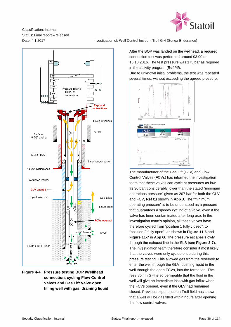
Figure 4-4 Pressure testing BOP /Wellhead connection, cycling Flow Control Valves and Gas Lift Valve open, filling well with gas, draining liquid
After the BOP was landed on the wellhead, a required connection test was performed around 03:00 on 15.10.2016. The test pressure was 175 bar as required in the activity program (Ref /4/). Due to unknown initial problems, the test was repeated several times, without exceeding the agreed pressure.
The manufacturer of the Gas Lift (GLV) and Flow Control Valves (FCVs) has informed the investigation team that these valves can cycle at pressures as low as 30 bar, considerably lower than the stated “minimum operations pressure” given as 207 bar for both the GLV and FCV, Ref /1/ shown in App J. The “minimum operating pressure” is to be understood as a pressure that guarantees a speedy cycling of a valve, even if the valve has been contaminated after long use. In the investigation team’s opinion, all these valves have therefore cycled from “position 1 fully closed”, to “position 2 fully open”, as shown in Figure 11-6 and Figure 11-7 in App G. The pressure escapes slowly through the exhaust line in the SLS (see Figure 3-7). The investigation team therefore consider it most likely that the valves were only cycled once during this pressure testing. This allowed gas from the reservoir to enter the well through the GLV, pushing liquid in the well through the open FCVs, into the formation. The reservoir in G-4 is so permeable that the fluid in the well will give an immediate loss with gas influx when the FCVs opened, even if the GLV had remained closed. Previous experience on Troll field has shown that a well will be gas filled within hours after opening the flow control valves.

Classification: Internal Status: Final report – released Date: 4.1.2017
Investigation of: Well Control Incident Troll G-4 (Songa Endurance)
Security Classification: Internal Status: Final report – released Page 37 of 114
Figure 4-5 Connecting Tubing Hanger Secondary Retrieval Tool to Tubing Hanger
The driller landed the tubing hanger secondary retrieval tool (THSRT) on the tubing hanger. To connect the THSRT to the tubing hanger lock sleeve, it was necessary to use higher torque than the maximum 10 kNm stated in the Detailed Operation Procedure 090. Senior tool pusher and Statoil’s drilling supervisor was already present in the driller’s cabin. It was agreed to increase the torque, and at 30 kNm torque, the shear pin in the THSRT sheared. The THSRT was then rotated a couple of turns to lock it in the tubing hanger lock sleeve. An inspection report from GE Oil&Gas found dirt accumulations, pieces of O-rings and various metal shavings in the TH, in addition to damage to the electrical stab in the TH. The cause is most likely a misalignment between TH and THSRT. All previous versions of the Detailed Operation Program 090 “Pull TH & upper completion using THSRT” (DOP 090) except the final (shown in App I), describe the risk of gas below the tubing hanger, and that the annulus preventer (AP) should be closed before unlocking the tubing hanger locking sleeve by over pull (lifting in addition to the weight of the drill pipe) of 18 tons, lifting the string no more than 75 mm. The final, signed version did not include closing of the annular preventer, to easier allow to lift the tubing hanger 75 mm. In the DOP, the commented risk for gas was moved to the operation column of the DOP This had been discussed the previous evening by Statoil and GE Oil & Gas personnel, before updating the DOP 090. The investigation team was informed that no one from Songa Offshore were present during this discussion. Statoil Drilling Superintendent was not informed. The Troll Main Activity Program states (Ref /3/, section 4.3.8) and interviewees were aware that there could be small amounts of gas (H2S, CO or hydrocarbons) present in the annulus when pulling the tubing hanger, but the risk of gas at reservoir pressure was not considered. The figure to the left show that the primary barrier is opened by the cycling of GLV and FCVs to open position, filling parts of the well with gas (shown in yellow).

Classification: Internal Status: Final report – released Date: 4.1.2017
Investigation of: Well Control Incident Troll G-4 (Songa Endurance)
Security Classification: Internal Status: Final report – released Page 38 of 114
Figure 4-6 Tubing hanger pulled, pushed 6 meters up by gas pressure in well
As the driller had lifted with 13 tons over pull, this over pull collapsed the hold down dogs (released the tubing hanger). The drill string then came up through the rotary, being pushed by the gas pressure (110 bar) in the well. This happened at 09:32:30 according to logged data of the hook load. The sea water filled riser was emptied by the escaping gas. The string came up approximately 6 meters before it halted as the compensator system stroked out. Observation on drill floor showed that water started flowing onto the drill floor 15 seconds after the drill pipe started to move. The pipe was curved due to compression by the upward force from the gas pressure (logs indicate 15-20 ton acting on it). The annular preventer was manually activated 19 seconds later at 09:33:04. Shortly after, there was no visibility; neither from drillers cabin nor in the surveillance cameras on drill floor due to seawater from riser emerging through rotary. Surveillance cameras showed the water column from the marine riser striking the top of the derrick, and being spread horizontally outwards.
The first gas alarm (20 % Lower Explosion Limit - LEL) was activated at 09:33:31 in an air inlet to a heavy tool store located ~10 m outside the wind wall of the derrick. This automatically shut down non-Ex equipment in that area. Five seconds later, another gas sensor in the same air inlet was activated, giving confirmed gas signal (more than one sensor at 20 % LEL). Simultaneously, gas sensors at on the drill floor started to give alarm. The two gas sensors at drill floor also gave 60 % LEL alarm. A single gas alarm gives alarm signal at the bridge (control room). Two gas alarms in the same area also trigger a partial Emergency Shutdown for that area, i.e. shut down ventilation and alerts personnel in all areas by sounding the general alarm. The figure to the left shows both barriers opened when the tubing hanger was lifted out of the wellhead.

Classification: Internal Status: Final report – released Date: 4.1.2017
Investigation of: Well Control Incident Troll G-4 (Songa Endurance)
Security Classification: Internal Status: Final report – released Page 39 of 114
Figure 4-7 Annular preventer closed. The red envelope is the single barrier containing pressure
The driller asked the senior tool pusher who was present in the drillers cabin, to activate the annular preventer (AP). This was done at 09:33:04, 34 seconds after the uncontrolled movement of the drill pipe. The AP takes 37 seconds to fully close, which would be at 09:33:41. Visibility on drill floor was restored at 09:33:42.
It was then observed that the two halves of the split bushings (weighing approximately 1 000 kg each) had been pushed out of the rotary. One piece had landed close to the driller’s cabin which is 6 metre from the rotary, the other half had gone the opposite direction.
The PS-21 slips (weighing approximately 2.5 ton including inserts) had fallen down on the diverter below the drill floor as the split bushings had been removed. A hydraulic hose for the PS21 slips had been torn off and hydraulic oil leaked out on drill floor. The hydraulic oil was collected in the closed drain system for slop.
Later, the riser was refilled with 54 m3 sea water. The riser annulus volume is estimated to 65 m3 (using the inner diameter of the riser and subtracting the diameter of the drill pipe), indicating that the riser was not completely emptied for water by the escaping gas.
Split bushing
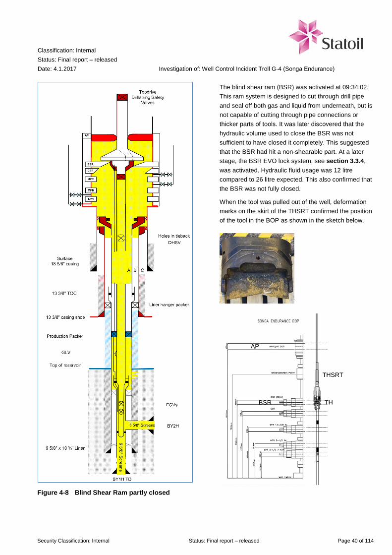
Classification: Internal Status: Final report – released Date: 4.1.2017
Investigation of: Well Control Incident Troll G-4 (Songa Endurance)
Security Classification: Internal Status: Final report – released Page 40 of 114
Figure 4-8 Blind Shear Ram partly closed
The blind shear ram (BSR) was activated at 09:34:02. This ram system is designed to cut through drill pipe and seal off both gas and liquid from underneath, but is not capable of cutting through pipe connections or thicker parts of tools. It was later discovered that the hydraulic volume used to close the BSR was not sufficient to have closed it completely. This suggested that the BSR had hit a non-shearable part. At a later stage, the BSR EVO lock system, see section 3.3.4, was activated. Hydraulic fluid usage was 12 litre compared to 26 litre expected. This also confirmed that the BSR was not fully closed.
When the tool was pulled out of the well, deformation marks on the skirt of the THSRT confirmed the position of the tool in the BOP as shown in the sketch below.
AP
BSR
THSRT
TH

Classification: Internal Status: Final report – released Date: 4.1.2017
Investigation of: Well Control Incident Troll G-4 (Songa Endurance)
Security Classification: Internal Status: Final report – released Page 41 of 114
4.2.1 Pressure readings in choke line immediately after the incident
Before releasing the tubing hanger, the choke line was opened against the well and an automatic choke on the choke manifold was closed. Between 10:10 and 10:20, after filling the riser, it was observed a gain/overflow in trip tank B. An automatic valve upstream the leaking choke on the choke manifold was reported closed at 10:21 to isolate the leaking choke. See choke manifold line-up sketch in App H. In addition, it was reported 74 bar pressure down to the cement unit. A manual valve on the cement test line was closed to isolate the cement unit from the choke manifold. It is noted that the casing shut in pressure is inconclusive in the period between the well was shut in at 09:34, and until the leaking choke was isolated at 10:21. After the valve was closed, the shut in casing pressure increased rapidly from ca. 20 to 50 bar, and continued to increase in accordance to reservoir pressure. It is considered likely that water and possibly gas had been escaping through the choke line via the leaking choke and to the mud gas separator (poor boy degasser). Water from the mud gas separator flowed to trip tank B. Any gas would have been vented up the 12” vent line above the top of the derrick. An eye witness reported observation of gas coming out of the vent line from the mud gas separator, but the exact time and details of this information is uncertain. It can be concluded that volume control while filling of the riser with the trip tank pump and booster line was difficult due to unknown water level in the riser. From the information available it has not been possible for the investigation team to conclude on more specific details of the situation following immediately after the incident (duration, rate, mud/gas etc.). The recorded data prior to the incident and until the choke valve was closed, and shut in pressure started to rise, is shown in Figure 4-9. Note that the indicated time is one hour before Norwegian time zone otherwise used in this report. Pressure data from the mud gas separator shows two low (0.15-0.06 bar) measurements from 09:34:22, less than a minute after the well was shut in (09:33:41). This may indicate that gas or fluid has been entering the mud gas separator, but the recorded measurements are too few to be conclusive. Readings are shown in Figure 4-10 and Figure 4-11.
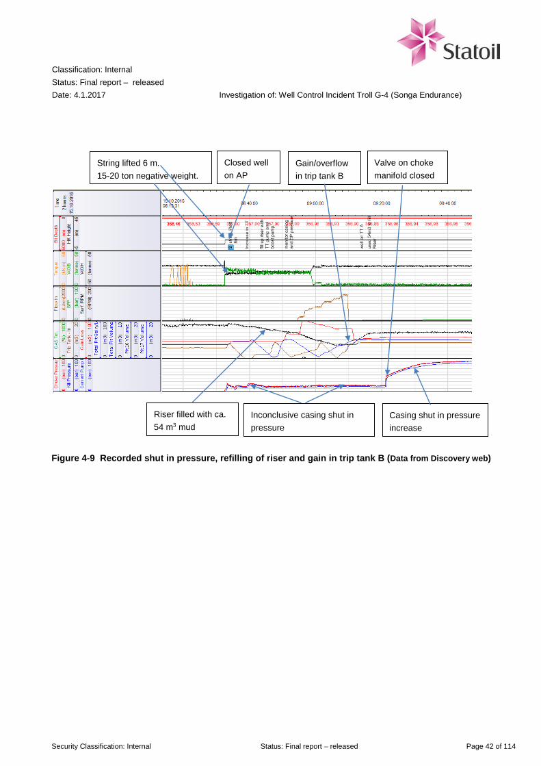
Classification: Internal Status: Final report – released Date: 4.1.2017
Investigation of: Well Control Incident Troll G-4 (Songa Endurance)
Security Classification: Internal Status: Final report – released Page 42 of 114
Figure 4-9 Recorded shut in pressure, refilling of riser and gain in trip tank B (Data from Discovery web)
Riser filled with ca. 54 m3 mud
Inconclusive casing shut in pressure
Closed well on AP
Valve on choke manifold closed
Gain/overflow in trip tank B
Casing shut in pressure increase
String lifted 6 m. 15-20 ton negative weight.

Classification: Internal Status: Final report – released Date: 4.1.2017
Investigation of: Well Control Incident Troll G-4 (Songa Endurance)
Security Classification: Internal Status: Final report – released Page 43 of 114
Figure 4-10 24 hour recorded pressure in Mud Gas Degasser (Note: Add two hours to get Norwegian time zone)
Figure 4-11 30 minutes recorded pressure in Mud Gas Degasser (Note: Add two hours to get Norwegian time zone)
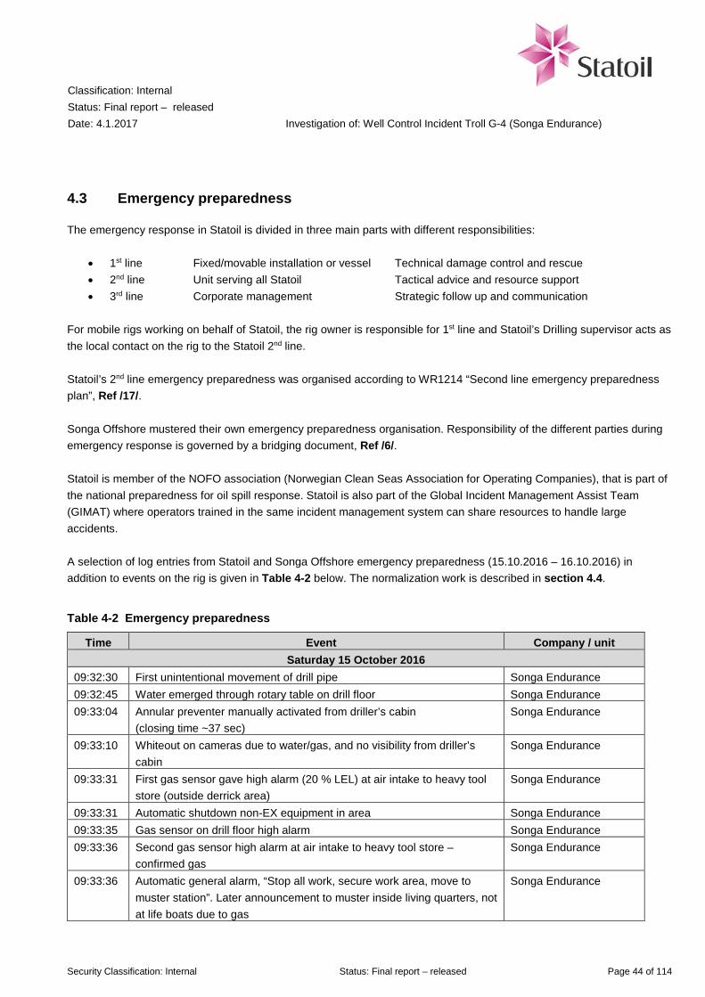
Classification: Internal Status: Final report – released Date: 4.1.2017
Investigation of: Well Control Incident Troll G-4 (Songa Endurance)
Security Classification: Internal Status: Final report – released Page 44 of 114
4.3 Emergency preparedness
The emergency response in Statoil is divided in three main parts with different responsibilities:
• 1st line Fixed/movable installation or vessel Technical damage control and rescue • 2nd line Unit serving all Statoil Tactical advice and resource support • 3rd line Corporate management Strategic follow up and communication
For mobile rigs working on behalf of Statoil, the rig owner is responsible for 1st line and Statoil’s Drilling supervisor acts as the local contact on the rig to the Statoil 2nd line. Statoil’s 2nd line emergency preparedness was organised according to WR1214 “Second line emergency preparedness plan”, Ref /17/. Songa Offshore mustered their own emergency preparedness organisation. Responsibility of the different parties during emergency response is governed by a bridging document, Ref /6/. Statoil is member of the NOFO association (Norwegian Clean Seas Association for Operating Companies), that is part of the national preparedness for oil spill response. Statoil is also part of the Global Incident Management Assist Team (GIMAT) where operators trained in the same incident management system can share resources to handle large accidents. A selection of log entries from Statoil and Songa Offshore emergency preparedness (15.10.2016 – 16.10.2016) in addition to events on the rig is given in Table 4-2 below. The normalization work is described in section 4.4.
Table 4-2 Emergency preparedness
Time Event Company / unit Saturday 15 October 2016
09:32:30 First unintentional movement of drill pipe Songa Endurance 09:32:45 Water emerged through rotary table on drill floor Songa Endurance 09:33:04 Annular preventer manually activated from driller’s cabin
(closing time ~37 sec) Songa Endurance
09:33:10 Whiteout on cameras due to water/gas, and no visibility from driller’s cabin
Songa Endurance
09:33:31 First gas sensor gave high alarm (20 % LEL) at air intake to heavy tool store (outside derrick area)
Songa Endurance
09:33:31 Automatic shutdown non-EX equipment in area Songa Endurance 09:33:35 Gas sensor on drill floor high alarm Songa Endurance 09:33:36 Second gas sensor high alarm at air intake to heavy tool store –
confirmed gas Songa Endurance
09:33:36 Automatic general alarm, “Stop all work, secure work area, move to muster station”. Later announcement to muster inside living quarters, not at life boats due to gas
Songa Endurance

Classification: Internal Status: Final report – released Date: 4.1.2017
Investigation of: Well Control Incident Troll G-4 (Songa Endurance)
Security Classification: Internal Status: Final report – released Page 45 of 114
Time Event Company / unit 09:33:36 Automatic Exhaust damper shutdown, supply damper shutdown,
exhaust fan shutdown Songa Endurance
09:33:41 Annular preventer assumed to be closed using closing time 37 seconds Songa Endurance 09:33:42 Visibility restored on cameras Songa Endurance 09:33:50 Second gas sensor high alarm on drill floor – confirmed gas Songa Endurance 09:34:03 Blind shear ram manually activated from driller’s cabin Songa Endurance 09:39 Songa Incident commander, 2nd line informed. No need for immediate
assistance Songa Offshore 2nd line
09:40 Emergency preparedness vessel “Stril Merkur” departed from Oseberg Sør, headed for Songa Endurance
Stril Merkur
09:50 Statoil Drilling Supervisor on Songa Endurance notified Statoil Main Notification Center. No need for immediate assistance
Statoil Main Notification Center
09:50 Songa Offshore 3rd line notified by Songa 2nd line Songa Offshore 3nd line 09:50 Statoil Drilling Superintendent on duty (by coincidence the Drilling
Superintendent for Songa Endurance) was notified and called rest of the duty team
Statoil Troll unit
09:58 Chief of staff, Statoil 2nd line notified by Statoil Main Notification Center Statoil 2nd line 10:02 POB (Personnel on Board) control OK – 107. No injuries
Delayed POB control due to some persons moving between locations during count
Songa Endurance
10:11 Joint Rescue Coordination Centre (HRS) updated Songa Endurance 10:12 Drilling & Well - Mobile Drilling Units, Troll duty team mustered at
Sandsli, Bergen
10:21 Closed an open valve on kill/choke manifold, choke line pressure started to increase from ~10 bar to about 100 bar
Songa Endurance
10:25 Remote Operated Vehicle in sea to survey the BOP Songa Endurance 10:29 First meeting Songa 2nd line Songa Offshore 2nd line 10:43 Statoil managers in relevant business units informed Statoil 3nd line 11:00 Statoil 2nd line mustered at office in Bergen Statoil 2nd line 11:00 Noticed that EVO locks to lock BSR used only 12 litres, less than the 26
litres expected. Indicated that BSR was not fully closed Songa Endurance
11:32 Songa Offshore VP Norway/UK notified Songa Offshore 3rd line 11:45 Stril Merkur on location (emergency vessel) Stril Merkur 12:00 Troll engineering team mustered at office in Bergen. See more details in
section 4.4 Statoil Troll unit
12:30 PSA notified and informed about incident Statoil 2nd line 13:31 First notice on incident released to media Statoil 3nd line 13:45 NOFO (Norwegian Clean Seas Association for Operating Companies)
contacted for satellite or other types of pollution surveillance NOFO (Norwegian Clean Seas Association for Operating Companies)
16:30 Emergency disconnect plan was prepared in case annular failed Songa Endurance 16:30 Arrival of extra drilling supervisor, drilling engineer and tool pusher
offshore Songa Endurance
16:52 Two people evacuated from the rig to Troll A platform Songa Endurance 17:38 15 people evacuated from the rig to Troll A Songa Endurance 18:25 Norwegian Flag State (Sjøfartdirektoratet) was notified Songa Offshore 2nd line
Classification: Internal Status: Final report – released Date: 4.1.2017
Investigation of: Well Control Incident Troll G-4 (Songa Endurance)
Security Classification: Internal Status: Final report – released Page 46 of 114
Time Event Company / unit 19:39 Arrival of extra tool pusher and Songa subsea engineer offshore Songa Endurance 20:00 The vessel “Ocean Art” arrived Songa Endurance with 45 m3 MEG Ocean Art Evening The PS21 slips that had fallen down on the diverter was removed
manually to avoid it locking onto the drill string Songa Endurance
Sunday 16 October 2016 12:08 Rig started to pump 50/50 MEG / sea water to stabilize and reduce
pressure in well Songa Endurance
15:51 Statoil 3rd line demobilized Statoil 3nd line Through interviews and emergency preparedness logs, the investigation team consider that the consequences of the incident were unclear during the early stages. 2nd line in both Statoil and Songa mustered when notified, even if the responders offshore were unclear whether mustering was required. The seriousness of the situation became clearer for the personnel on the rig around 11:00 on 15 October 2016, when they discovered that the blind shear ram had not cut and sealed the well successfully. In addition, the low and stable shut in pressure readings (due to a leaking choke, actual shut in pressure would have been higher than readings indicated) discussed in section 4.2.1 seemed to indicate that the situation was a smaller volume of gas trapped under the BOP. The pressure increased as the manual valve on the choke manifold was closed.
4.4 Normalizing work carried out from 15.10 until 26.10.2016
Statoil’s department for mobile drilling units on Troll mobilized a multi-discipline team to assist the rig in solving the well control incident and normalize the situation. In addition to people on duty call, several others were contacted and met at the office in Bergen. It was also decided already in the afternoon 15 October 2016 that there was need for around the clock support, and rotation plans were set up. More than 30 people were involved, including personnel from the XT/ wellhead supplier GE Oil & Gas. The team was divided in “Operations” and “Engineering”, sitting in separate rooms. In addition, Statoil’s Subsurface Support Center (SSC) in Stavanger was mobilized to give additional support. The activity program for well G-4 contained a section (Ref /4/ section 2.6) describing the location of two possible relief wells. Two persons in the normalization team and one in the Subsurface Support Centre started to survey available rig resources for relief well drilling and/or capping operation, and to mobilize equipment for these rigs to perform a temporary plug and abandonment on the wells they were currently working on. This work was continued by one person on Sunday 16 October 2016, and finally stopped on Tuesday 18 October 2016. A separate task force for planning relief wells in detail, as described in DW904, Ref /11/ was not established. On Sunday 16 October 2016, the annulus of the well was killed. Fluid was pumped to compensate for loss to the formation. A total of 14 different solutions to remove the trapped gas in the tubing without pulling the gas volume above the BOP was discussed, shown in App C. Much effort was used to identify risk of each alternative, and how one failed attempt could exclude the possibility to try other solutions. To visualize this, a comprehensive flow chart was developed. The flow chart also included an emergency procedure in case the annular preventer failed. Being requested by the driller, this was developed on the rig already on the afternoon 15 October, and shown in Figure 4-12. The tubing of the well was killed 26 October.
Classification: Internal Status: Final report – released Date: 4.1.2017
Investigation of: Well Control Incident Troll G-4 (Songa Endurance)
Security Classification: Internal Status: Final report – released Page 47 of 114
A preliminary experience summary for Statoil’s normalization team has been prepared (not finalized as per 29.11.2016). Some of the main learnings, observations and recommendations are:
• Use 08-20 / 20-08 and 12-24 shifts to improve handover between shifts • Set up common email-box where all information is sent to ensure all get the required information • Improve communication between “Operations” and “Engineering” with status meetings • Set up a small group to look at long term strategy • Over respond in mobilizing resources (easier to demobilize if needed)
The investigation team was given full access to the dedicated team site set up to store all documents produced during the normalization work. The investigation team has also conducted interviews and meetings with involved personnel. In the investigation team’s opinion, the normalization work was conducted in a professional manner. It had focus on choosing solutions that did not exclude other options if they should fail. In addition, several of the rig personnel affected by the incident have commented to the investigation team that they were satisfied with the way the evacuation and onshore reception of them was handled.

Classification: Internal Status: Final report – released Date: 4.1.2017
Investigation of: Well Control Incident Troll G-4 (Songa Endurance)
Security Classification: Internal Status: Final report – released Page 48 of 114
Figure 4-12 Emergency procedure prepared on Songa Endurance 15.10.2016 around 16:30
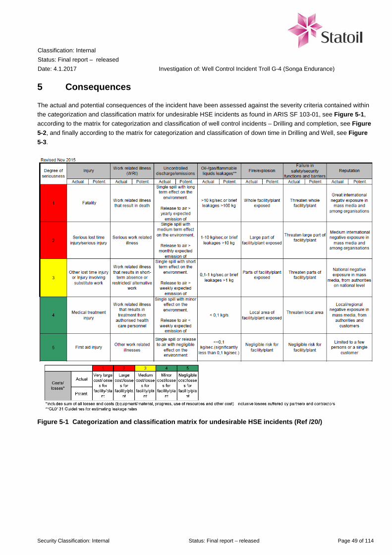
Classification: Internal Status: Final report – released Date: 4.1.2017
Investigation of: Well Control Incident Troll G-4 (Songa Endurance)
Security Classification: Internal Status: Final report – released Page 49 of 114
5 Consequences
The actual and potential consequences of the incident have been assessed against the severity criteria contained within the categorization and classification matrix for undesirable HSE incidents as found in ARIS SF 103-01, see Figure 5-1, according to the matrix for categorization and classification of well control incidents – Drilling and completion, see Figure 5-2, and finally according to the matrix for categorization and classification of down time in Drilling and Well, see Figure 5-3.
Figure 5-1 Categorization and classification matrix for undesirable HSE incidents (Ref /20/)

Classification: Internal Status: Final report – released Date: 4.1.2017
Investigation of: Well Control Incident Troll G-4 (Songa Endurance)
Security Classification: Internal Status: Final report – released Page 50 of 114
Figure 5-2 Matrix for categorization and classification of well control incidents – Drilling and Completion Operations (Ref /23/ and /30/)
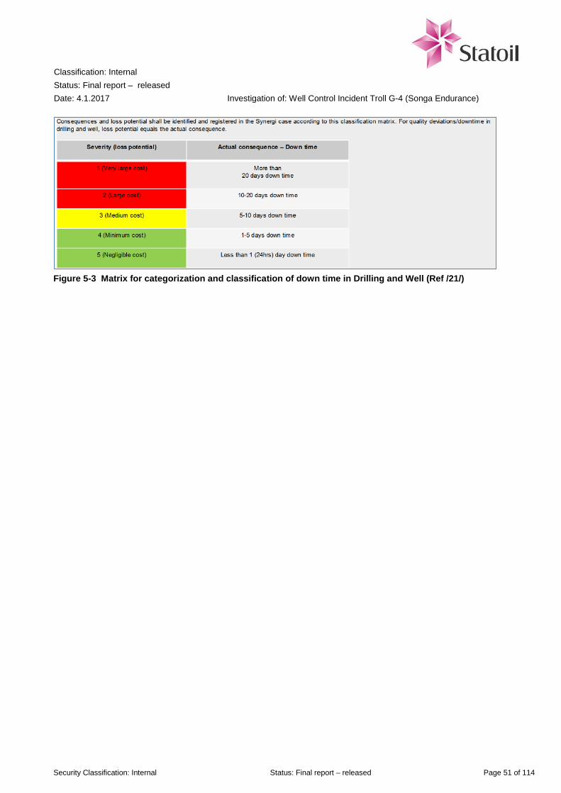
Classification: Internal Status: Final report – released Date: 4.1.2017
Investigation of: Well Control Incident Troll G-4 (Songa Endurance)
Security Classification: Internal Status: Final report – released Page 51 of 114
Figure 5-3 Matrix for categorization and classification of down time in Drilling and Well (Ref /21/)

Classification: Internal Status: Final report – released Date: 4.1.2017
Investigation of: Well Control Incident Troll G-4 (Songa Endurance)
Security Classification: Internal Status: Final report – released Page 52 of 114
5.1 Actual consequences
5.1.1 Injury
There was no personal injury due to the incident. The ROV (subsea remote operated vehicle) crew was in the ROV unit located on a lower level at main deck aft. They had to evacuate approximately 10 metre across deck through gas exposed area before entering enclosed area. They did not have access to pressurized air or escape masks. No later damage or injury have been reported.
5.1.2 Work related illness
The investigation team has so far not been informed about any work related illness caused by the incident. However, the team consider it too early to conclude if there will be future work related illness cases linked to short or long term effects on those involved in this well control incident.
5.1.3 Uncontrolled discharge / emissions
There was a leak from the hydraulic control line to the PS 21 slips, as this was torn off during the incident when the slips fell down on the diverter element. The hydraulic oil was collected in closed drain. No other uncontrolled discharge has been reported. According to the classification matrix in Figure 5-1, the investigation team classifies this as an actual level of seriousness Green 5 “Single spill with negligible effect on the environment”.
5.1.4 Oil / gas / flammable liquids leakages
Gas detectors in two different zones (039 – outside the derrick and 041 – on the drill floor) gave 20 and 60 % LEL alarms. Using the smallest actual inner diameter of the BOP (476.63 mm) and the largest diameter of the THSRT tool inside the BOP, (471.42 mm), the gas from the well could escape through an area calculated to 3879 mm2. With the assumed gas pressure of 110 bar and hydrostatic pressure from liquid in the riser of 35 bar, the initial leak rate was calculated using the software program PHAST supplied by DNV-GL to 47.6 kg/sec. This rate will increase as the liquid escapes the riser, leading to a lower hydrostatic pressure. With zero hydrostatic pressure, the leak is calculated to 70.7 kg/sec with a gas velocity of 649 m/sec. As the annular preventer started to close, the leak rate would decrease as the effective area decreased. The gas leak is assumed to have lasted approximately one minute. Using the classification matrix in Figure 5-1, the investigation team classifies this as an actual level of seriousness Red 1 “> 10 kg/sec”.
5.1.5 Fire / explosion
The gas leak was not ignited.
5.1.6 Failure in safety functions and barriers
The primary well barrier, with the two flow control valves (FCVs) and gas lift valve (GLV), had failed when the valves were opened, draining the well of the fluid column and allowing gas to enter the well. The secondary well barrier envelope was opened when the tubing hanger was released, as the tubing hanger was pushed by the reservoir gas at 110 bar pressure. The gas then escaped through the un-activated BOP, up the sea water filled marine riser, and escaped, partially mixed with the sea water, through the rotary table on drill floor. Until the annular preventer (AP) closed, after
Classification: Internal Status: Final report – released Date: 4.1.2017
Investigation of: Well Control Incident Troll G-4 (Songa Endurance)
Security Classification: Internal Status: Final report – released Page 53 of 114
having been manually activated by personnel in the driller’s cabin, there were no active well barriers preventing hazardous gas to flow out of the well. The annular preventer was manually activated by personnel in the driller’s cabin, and managed to contain the gas. The investigation team classifies this as actual level of seriousness Red 2 “Failure of safety functions and barriers that threaten large part of the facility (i.e. several modules)” according to the classification matrix in Figure 5-1.
5.1.7 Reputation
The incident is being investigated by the Norwegian Petroleum Safety Authority, and was reported in national and international media. International media also reported that the Norwegian Petroleum Safety Authority called for a meeting with Statoil management after a number of recent incidents involving Statoil’s assets, among them the G-4 well control incident. Using the classification matrix in Figure 5-1, the investigation team classifies this as an actual level of seriousness Red 2 “Medium international negative exposure in mass media and among organisations”.
5.1.8 Costs / losses and down time
The normalization work took 14 days, involving offshore personnel and on-shore day and night support teams from Statoil, Songa Offshore and suppliers. Statoil’s incident reporting system, Synergi report 1490145 documents that the incident as of present caused 22.4 days down time, with total cost approximately 132 Million NOK. The investigation team classifies this as actual level of seriousness Red 1 “Very large costs / losses for the installation”, including partners and contractors, according to the classification matrix in Figure 5-1 and Figure 5-3.
5.2 Classification according to matrix for well incidents, GL0455
In addition to using the matrix shown in Figure 5-1, well control incidents shall be classified according to Statoil’s guideline GL0455, Ref /23/, which in turn is based on Norwegian Oil and Gas recommendation 135, Ref /30/. The investigation team has concluded that the incident is classified as Red – Level 1.2 High HC influx rate according to the matrix shown in Figure 5-2. This classification is supported by Statoil’s Leading Advisor for Well Control.
Classification: Internal Status: Final report – released Date: 4.1.2017
Investigation of: Well Control Incident Troll G-4 (Songa Endurance)
Security Classification: Internal Status: Final report – released Page 54 of 114
5.3 Potential consequences
The investigation team has assessed the potential consequences of the incident in slightly different circumstances. “Slightly different circumstances” is defined in Statoil governing documentation to mean that it is only by chance that alternative outcomes of the incident did not occur, and not what could have happened in worst case. Statoil’s governing documentation includes a guideline for classification of potential consequences, GL0604 (Ref /25/). Several of the potential consequences are influenced by the placement of the rig. Based on the investigation team’s assessment that only slightly changed circumstances would have led to a decision to remove the rig from the well, the team finds it relevant to assess potential consequences also for this scenario. The following conditions could individually, if changed slightly, have led to a decision to remove the rig from the well.
• The weather conditions at the time of the incident (1 m wave height), and the following days, were better than typical for October in the North Sea. Mean significant wave height for October and November is 3.0 m and 3.4 m respectively (Ref /42/). Higher waves would have made it difficult or impossible for the heave compensation system to handle the vertical movements of the rig without inducing load on the wellhead since the drill string was stuck in the BOP
• The annular preventer closed on a slick part of the tubing hanger secondary recovery tool. Other parts of the tool had uneven surface and protrusions that would make it less probable that the annular had been able to seal the gas from the reservoir
• The PS21 slips fell down from the rotary, and landed on the diverter below deck. It could have locked on the drill string, but rig personnel were able to remove the PS21 slips later on 15.10.2016
• Personnel present in the driller’s cabin activated the annular preventer 19 seconds after water started flowing from the well. The potential consequence of the incident was reduced by the rapid response by the crew, and the short closing time of the annular element (37 seconds actual closing time versus 45/60 seconds which is the requirement). In this incident the annular preventer was used to control a full flowing well.
The rig had prepared an emergency procedure to escape by releasing four of the anchor lines on one side, and then being pulled away from the well by the four anchor lines on the opposite side. The load sheaves for the anchor lines are sprayed with water to reduce probability of sparks igniting any gas present. The investigation team has been informed by the marine superintendent in Songa Offshore that the rig could be moved about 100 meters in 5 minutes, including the 30 seconds used by the emergency disconnect sequence. If no gas was present, the thrusters could have been used to move the rig faster and further away.
5.3.1 Injury
There were no personnel present in the red zone on drill floor during the incident. Unless documented in a risk analysis, the red zone is unmanned when equipment is in motion. In this incident, the two halves of the split bushing (each weighing approximately 1 000 kg) where lifted out from their location in the rotary by the emerging sea water from the riser, and moved several meters to each side. The yellow circle to the right indicates where one of the bushings landed, it was close to the driller’s cabin. The windows are protected by steel grating, but most likely would not have been able to stop the heavy split bushing if it had hit. In case of an explosion, other objects could also have hit areas inside and outside of the drill floor. Personnel in the driller’s cabin would also most likely have been fatally injured if the gas had ignited, see section 5.3.5.

Classification: Internal Status: Final report – released Date: 4.1.2017
Investigation of: Well Control Incident Troll G-4 (Songa Endurance)
Security Classification: Internal Status: Final report – released Page 55 of 114
Figure 5-4 Rotary table with split bushings
The investigation team classifies the potential level of seriousness as Red 1 “Fatality” using the classification matrix in Figure 5-1.
5.3.2 Work related illness
The investigation team believes that under slightly different circumstances, some of the affected personnel would suffer long term work related illness. According to the classification matrix in Figure 5-1, this is classified as potential Red 2 “Serious work related illness”.
5.3.3 Uncontrolled discharge / emissions
As mentioned in section 5.3, the investigation team consider that the well control incident could have led to a decision to remove Songa Endurance from the well possibly without being able to first seal it off. Given that the gas lift valve was open, Petroleum Technology (PETEK) Troll has estimated that the G-4 incident potentially could lead to a daily spill of 155 m3 oil to sea. Had the gas lift valve been closed, the well would not produce. An environmental risk analysis for Troll was carried out by the consulting company DNV in 2013 (Ref /33/). The accumulated probability for duration of a subsea blowout up to 14 days is calculated in the report to 79 %. Given a duration of 14 days the total discharge would sum up to a total of 2170 m3 oil subsea. However, in the event of such a discharge, contingency measures would be implemented according to the oil spill preparedness plan for Troll. The first barrier would be in place near the source of the oil spill within 3 hours, after the initial release of approximately 20 m3 oil. With the first barrier in place, the spreading and the effects of further oil spill to sea following the subsea blowout would be reduced due to oil spill preparedness measures. According to the environmental risk analysis for Troll, the oil plume is expected to surface within 640 seconds. The oil dispersion modelling shows that an oil spill of this size will not have much of an influential area and only spread within the vicinity (a few kilometres) of the installation and probably not reach the coast line. According to the weathering studies,
Split bushings Driller’s cabin
Rotary table

Classification: Internal Status: Final report – released Date: 4.1.2017
Investigation of: Well Control Incident Troll G-4 (Songa Endurance)
Security Classification: Internal Status: Final report – released Page 56 of 114
the Troll oil will not evaporate, but remain on the sea surface for days before it gradually starts to disperse due to wind and weather after 2-3 days, unless exposed to strong wind. All together, these data suggest that a potential spill of 155 m3 oil daily for 14 days would not have any adverse environmental effects on a population level. However, birds and fish exposed at the location of the oil spill could have been adversely affected at an individual level. Using the classification matrix in Figure 5-1, the investigation team classifies this as a potential level of seriousness Yellow 3 “Single spill with short term effect on environment”.
5.3.4 Oil / gas / flammable liquids leakages
As described in section 5.1.4, the initial leak rate has been estimated to 47.6 kg/sec rising to 70.7 kg/sec as the riser was emptied of water. This is based on the assumed gas pressure in the well, the physical dimensions of the BOP, THSRT, riser and drill pipe, and the water depth at Troll. The investigation team does not consider that any of these factors would have changed under slightly different circumstances to give a higher initial leak rate. A study referred to in a book on quantitative risk assessments (Ref /32/) concludes that there is no potential for loss of buoyancy of a semi-submersible rig due to subsea gas blowout. However, there is potential for horizontal drift-off due to radial velocity of the water currents lifted by the gas plume. Using the classification matrix in Figure 5-1, the investigation team classifies this as a potential level of seriousness Red 1 “> 10 kg/sec”.
5.3.5 Fire / explosions
As recommended in GL0604 (Ref /25/), fire and explosion must be considered as a possible outcome of gas leakages under slightly different circumstances and states that the incident should normally not be classified with a lower potential for fire and explosion than the level of the potential leak. The quantitative risk analysis for Songa Endurance (Ref /35/, Attachment A3, section 3.3) states that the probability of immediate ignition (within five minutes) of a well release is 5 %. Further, the analysis concludes (Ref /35/, section 6.2) that fire on the drill floor from a well release could cause local failure on the drill string compensator and possibly impair escape routes locally, but “impairment of the rig itself or other main safety functions is considered very unlikely”. This means that other personnel could muster and evacuate in case of fire / explosion on the drill floor. The investigation team therefore classifies the potential level of seriousness as Red 2 “Large part of the facility exposed” using the classification matrix in Figure 5-1.
5.3.6 Failure in safety / security functions and barriers
As described in section 5.1.6, the investigation team consider that the primary well barrier had failed when the two flow control valves (FCVs) and gas lift valve (GLV) were opened, and that the secondary barrier failed when the tubing hanger was lifted from the wellhead by the gas pressure in the well. Full flow testing is not a specific requirement for BOP systems, ref section 3.3.4, even if the annular preventer worked in this case. The investigation team classifies this as potential level of seriousness Red 1 “Failure of safety functions and barriers that threaten the whole facility” according to the classification matrix in Figure 5-1.

Classification: Internal Status: Final report – released Date: 4.1.2017
Investigation of: Well Control Incident Troll G-4 (Songa Endurance)
Security Classification: Internal Status: Final report – released Page 57 of 114
5.3.7 Reputation
If the incident had turned into a blowout that would require capping or drilling of relief wells, the investigation team consider this as potential level of seriousness Red 1 “Great international negative exposure in mass media and among organisations” according to the classification matrix in Figure 5-1.
5.3.8 Costs / losses
The actual level of seriousness for this category was classified as highest level Red 1. The investigation team has not looked into what the costs of a long term blowout would be, but this is still at highest level Red 1 “Very large costs / losses for the installation”, including partners and contractors, according to the classification matrix in Figure 5-1 and Figure 5-3.

Classification: Internal Status: Final report – released Date: 4.1.2017
Investigation of: Well Control Incident Troll G-4 (Songa Endurance)
Security Classification: Internal Status: Final report – released Page 58 of 114
5.4 Assessment of major accident risk
A major accident is defined as consequence category 7 and 8 in Statoil’s HSE risk matrix, ref. ARIS R-24383, shown in App D. The probability of an incident escalating to a major accident depends upon the condition of consequence reducing barriers relative to the incident. The gas leaking from the well was almost pure methane. Methane has a lower explosion limit of about 5 % concentration, and an upper limit of about 15 %. Methane has a density of 0.716 g/litre at standard temperature and atmospheric pressure. At a leak rate of about 50 kg/sec this corresponds to about 70 m3/sec. Even if gas sensors give signal to cut the electrical power to non-Ex equipment, the gas would give a large cloud with gas in a concentration than could have ignited. According to the quantitative risk analysis for Songa Endurance (Ref /35/, Attachment A3, section 3.3) the probability of immediate ignition (within five minutes) of a well release is 5 %. There were six persons in the driller’s cabin. Additional people might have been in the so-called doghouse at the back side of the driller’s cabin (office for roughnecks). The station bill states that three roughnecks shall muster at drill floor to assist in the well securing team. All of these could have been exposed in an explosion on the drill floor. As shown in section 5.3.3, the investigation team consider the environmental impact to have only short term effects if the well control incident had turned into a subsea blowout from an oil producing well. To summarize, the investigation team considers the incident to be a potential major accident for the category People’s health and safety.
5.5 Incident classification
The following is a summary of the severity of for the different impact categories in the categorization and classification matrix, Figure 5-1. In the table "None" means that the consequence did not occur or could not have occurred.
Table 5-1 Classification of the incident
Consequence category Actual degree of severity Possible degree of severity under slightly different circumstances
Injury None Possible severity 1 Work related illness Too early to decide Possible severity 2 Uncontrolled discharge / emissions
Actual severity 5 Possible severity 3
Oil / gas / flammable liquids leakages
Actual severity 1 Possible severity 1
Fire / explosions None Possible severity 2 Failure in safety / security functions and barriers
Actual severity 2 Possible severity 1
Reputation Actual severity 2 Possible severity 1 Costs / losses Actual severity 1 Possible severity 1
The incident is classified with the highest severity Actual Red 1.

Classification: Internal Status: Final report – released Date: 4.1.2017
Investigation of: Well Control Incident Troll G-4 (Songa Endurance)
Security Classification: Internal Status: Final report – released Page 59 of 114
6 Causes
The Cause map (see Figure 6-1) provides an overview of the causes of the incident. The map shows the events that led to the unwanted consequence/loss, the immediate causes (unwanted/dangerous action or condition that triggered one or more single events), underlying causes and the relationships between them. The Cause map is established based on the description of sequence of events given in chapter 4. The investigation team has utilized a system-oriented approach to the investigation work. Rather than focusing on a single error or failure, the system approach views the causes of the incident as an interconnected web of technical problems, decisions, design issues, operational practices, organizational factors etc. which worked together to cause the incident.
Figure 6-1 Cause map
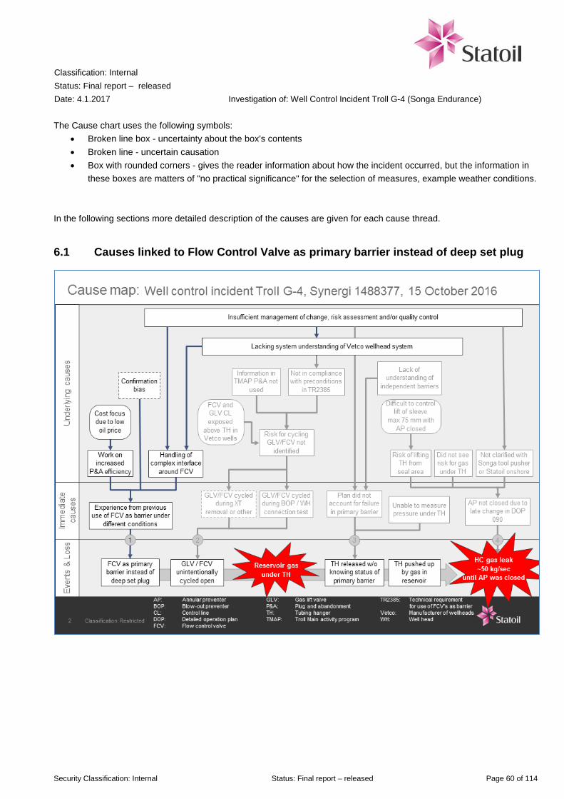
Classification: Internal Status: Final report – released Date: 4.1.2017
Investigation of: Well Control Incident Troll G-4 (Songa Endurance)
Security Classification: Internal Status: Final report – released Page 60 of 114
The Cause chart uses the following symbols: • Broken line box - uncertainty about the box's contents • Broken line - uncertain causation • Box with rounded corners - gives the reader information about how the incident occurred, but the information in
these boxes are matters of "no practical significance" for the selection of measures, example weather conditions. In the following sections more detailed description of the causes are given for each cause thread.
6.1 Causes linked to Flow Control Valve as primary barrier instead of deep set plug
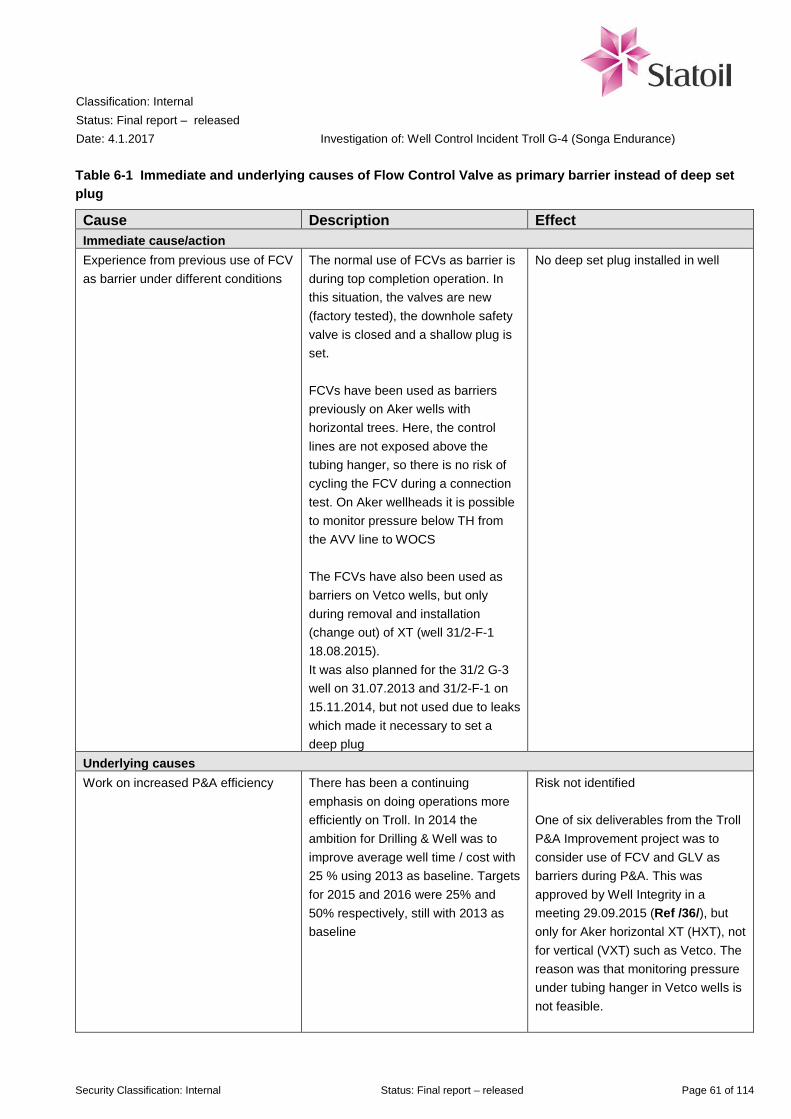
Classification: Internal Status: Final report – released Date: 4.1.2017
Investigation of: Well Control Incident Troll G-4 (Songa Endurance)
Security Classification: Internal Status: Final report – released Page 61 of 114
Table 6-1 Immediate and underlying causes of Flow Control Valve as primary barrier instead of deep set plug
Cause Description Effect Immediate cause/action Experience from previous use of FCV as barrier under different conditions
The normal use of FCVs as barrier is during top completion operation. In this situation, the valves are new (factory tested), the downhole safety valve is closed and a shallow plug is set. FCVs have been used as barriers previously on Aker wells with horizontal trees. Here, the control lines are not exposed above the tubing hanger, so there is no risk of cycling the FCV during a connection test. On Aker wellheads it is possible to monitor pressure below TH from the AVV line to WOCS The FCVs have also been used as barriers on Vetco wells, but only during removal and installation (change out) of XT (well 31/2-F-1 18.08.2015). It was also planned for the 31/2 G-3 well on 31.07.2013 and 31/2-F-1 on 15.11.2014, but not used due to leaks which made it necessary to set a deep plug
No deep set plug installed in well
Underlying causes Work on increased P&A efficiency There has been a continuing
emphasis on doing operations more efficiently on Troll. In 2014 the ambition for Drilling & Well was to improve average well time / cost with 25 % using 2013 as baseline. Targets for 2015 and 2016 were 25% and 50% respectively, still with 2013 as baseline
Risk not identified One of six deliverables from the Troll P&A Improvement project was to consider use of FCV and GLV as barriers during P&A. This was approved by Well Integrity in a meeting 29.09.2015 (Ref /36/), but only for Aker horizontal XT (HXT), not for vertical (VXT) such as Vetco. The reason was that monitoring pressure under tubing hanger in Vetco wells is not feasible.

Classification: Internal Status: Final report – released Date: 4.1.2017
Investigation of: Well Control Incident Troll G-4 (Songa Endurance)
Security Classification: Internal Status: Final report – released Page 62 of 114
Cause Description Effect In a 2016-01-27 memo from the Troll P&A improvement team, it is noted that “Item 4: Saving time prior to P&A: Evaluate to omit killing well on P&A's - plug only. Evaluate to use FCV & GLV as barriers during P&A (and completion), remote kill from prod. platform. Accepted from well integrity, see MOM. Closed.” This memo has no mentioning about the difference between the horizontal and vertical XT
Cost focus due to low oil price The sudden drop in oil price in 2014 has affected the whole oil industry. The oil price lies beyond Statoil’s control, but has increased focus on cost savings
Troll is said to always have had an optimization culture. The idea to use FCVs as barrier valves was launched before the sudden drop in oil price in 2014, and introduction of the STEP program. Still, the investigation team considers the oil price to influence the decision to increase the ambition to increase the P&A efficiency, ref targets for 2016 mentioned above
Confirmation bias Confirmation bias is the tendency to search for, interpret, favour and recall information in a way that confirms one’s pre-existing beliefs or hypothesis, while giving proportionately less consideration to alternative possibilities and risk assessment.
The preconditions for use of FCV/GLV as barrier in previous operations seems not to have been compared to the actual preconditions for the G-4 operations. The risks and reasons for “why not” seems not to have been examined thoroughly nor given much attention.
Handling of complex interface around FCV
Through interviews, the investigation team has been told that there are many disciplines involved concerning FCVs (e.g. Subsea-, completion- and drilling engineer, 3rd parties delivering valves or XTs) but they will not necessarily meet to get a common picture of which risks are involved in the different operations with different equipment combinations. In the risk meeting for detailed planning of G-4, many important stakeholders (Baker Hughes, GE Oil&Gas, Subsea) were not present, even though this was the first time
Completion engineer had planned the installation of the GLV and FCVs (in 2012 when G-4 B was side tracked), but to the investigation team’s knowledge was not involved in decision to use them for a completely different purpose, as barriers in the P&A. This has probably contributed to the use of the valves as barriers
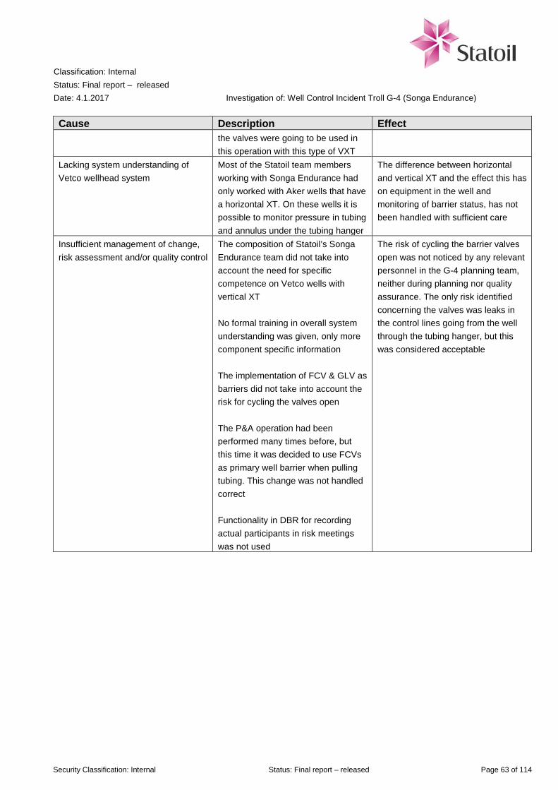
Classification: Internal Status: Final report – released Date: 4.1.2017
Investigation of: Well Control Incident Troll G-4 (Songa Endurance)
Security Classification: Internal Status: Final report – released Page 63 of 114
Cause Description Effect the valves were going to be used in this operation with this type of VXT
Lacking system understanding of Vetco wellhead system
Most of the Statoil team members working with Songa Endurance had only worked with Aker wells that have a horizontal XT. On these wells it is possible to monitor pressure in tubing and annulus under the tubing hanger
The difference between horizontal and vertical XT and the effect this has on equipment in the well and monitoring of barrier status, has not been handled with sufficient care
Insufficient management of change, risk assessment and/or quality control
The composition of Statoil’s Songa Endurance team did not take into account the need for specific competence on Vetco wells with vertical XT No formal training in overall system understanding was given, only more component specific information The implementation of FCV & GLV as barriers did not take into account the risk for cycling the valves open The P&A operation had been performed many times before, but this time it was decided to use FCVs as primary well barrier when pulling tubing. This change was not handled correct Functionality in DBR for recording actual participants in risk meetings was not used
The risk of cycling the barrier valves open was not noticed by any relevant personnel in the G-4 planning team, neither during planning nor quality assurance. The only risk identified concerning the valves was leaks in the control lines going from the well through the tubing hanger, but this was considered acceptable
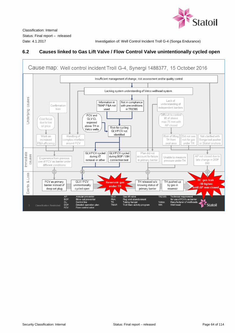
Classification: Internal Status: Final report – released Date: 4.1.2017
Investigation of: Well Control Incident Troll G-4 (Songa Endurance)
Security Classification: Internal Status: Final report – released Page 64 of 114
6.2 Causes linked to Gas Lift Valve / Flow Control Valve unintentionally cycled open

Classification: Internal Status: Final report – released Date: 4.1.2017
Investigation of: Well Control Incident Troll G-4 (Songa Endurance)
Security Classification: Internal Status: Final report – released Page 65 of 114
Table 6-2 Immediate and underlying causes of Gas Lift Valve / Flow Control Valve unintentionally cycled open
Cause Description Effect Immediate cause/action GLV/FCV cycled during XT removal or other operation
After Baker Hughes’s last cycle of FCVs and GLV and following pressure test of tubing the control line were connected to WOCS. It is possible to operate the FCV/GLV from the Work Over Control System (WOCS). When the XT was removed, pressure in the seal test area was applied to help lift off the XT.
-Unintentional operation of WOCS could operate FCV/GLV. -Unintentional pressure build up in return system in WOCS could cycle FCV/GLV -Damage to control line during cut of tubing could cause a leak in control line and a pressure increase of 30 bar to FCV/GLV due to heavier fluid in annulus. This potential also occurs later when pulling tubing and rupturing control line. -Pressure assist retrieval of XT (performed in DOP 070 Chapter 8 Item 9) could allow pressure to leak into control line for and cycle FCV/GLV, but is very unlikely according to the manufacturer
GLV/FCV cycled during BOP / Wellhead connection test
The investigation team believes it is most likely that the GLV and FCVs were cycled open during the connection test performed about 5.5 hours before the HC leak. Due to the poppet in the hydraulic couplers in the TH the pressure from the first pressure test was trapped in the control line and therefore the FCVs and GLV was most likely cycled only once, to 100% open.
With both the GLV and FCVs open, gas from the reservoir would stream into the well and drain the fluid out through the open FCVs into the well/oil reservoir
Underlying causes Risk for cycling GLV/FCV not identified
The risk for cycling the valves had not been identified by the project or through risk meetings and quality control. The BOP/Wellhead connection test was not covered by a Detailed Operation Procedure, only Songa routine procedure
If the connection test had been covered by a DOP, the risk might have been identified by a multi competence team, including suppliers
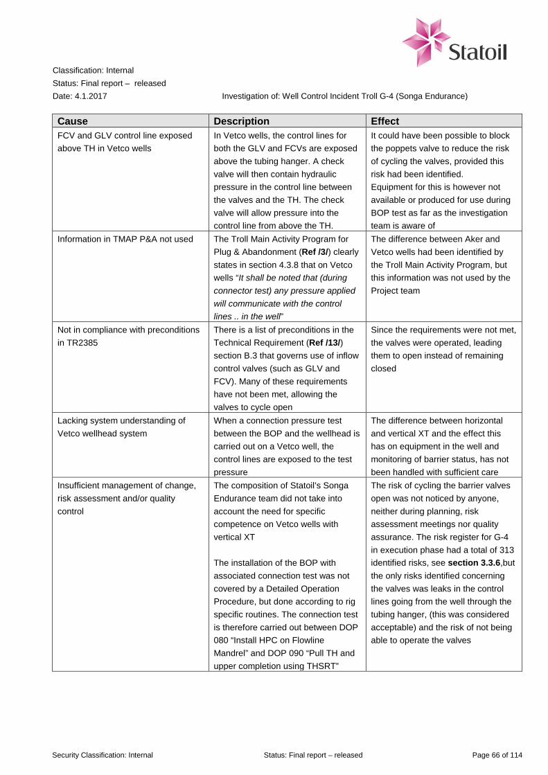
Classification: Internal Status: Final report – released Date: 4.1.2017
Investigation of: Well Control Incident Troll G-4 (Songa Endurance)
Security Classification: Internal Status: Final report – released Page 66 of 114
Cause Description Effect FCV and GLV control line exposed above TH in Vetco wells
In Vetco wells, the control lines for both the GLV and FCVs are exposed above the tubing hanger. A check valve will then contain hydraulic pressure in the control line between the valves and the TH. The check valve will allow pressure into the control line from above the TH.
It could have been possible to block the poppets valve to reduce the risk of cycling the valves, provided this risk had been identified. Equipment for this is however not available or produced for use during BOP test as far as the investigation team is aware of
Information in TMAP P&A not used The Troll Main Activity Program for Plug & Abandonment (Ref /3/) clearly states in section 4.3.8 that on Vetco wells “It shall be noted that (during connector test) any pressure applied will communicate with the control lines .. in the well”
The difference between Aker and Vetco wells had been identified by the Troll Main Activity Program, but this information was not used by the Project team
Not in compliance with preconditions in TR2385
There is a list of preconditions in the Technical Requirement (Ref /13/) section B.3 that governs use of inflow control valves (such as GLV and FCV). Many of these requirements have not been met, allowing the valves to cycle open
Since the requirements were not met, the valves were operated, leading them to open instead of remaining closed
Lacking system understanding of Vetco wellhead system
When a connection pressure test between the BOP and the wellhead is carried out on a Vetco well, the control lines are exposed to the test pressure
The difference between horizontal and vertical XT and the effect this has on equipment in the well and monitoring of barrier status, has not been handled with sufficient care
Insufficient management of change, risk assessment and/or quality control
The composition of Statoil’s Songa Endurance team did not take into account the need for specific competence on Vetco wells with vertical XT The installation of the BOP with associated connection test was not covered by a Detailed Operation Procedure, but done according to rig specific routines. The connection test is therefore carried out between DOP 080 “Install HPC on Flowline Mandrel” and DOP 090 “Pull TH and upper completion using THSRT”
The risk of cycling the barrier valves open was not noticed by anyone, neither during planning, risk assessment meetings nor quality assurance. The risk register for G-4 in execution phase had a total of 313 identified risks, see section 3.3.6,but the only risks identified concerning the valves was leaks in the control lines going from the well through the tubing hanger, (this was considered acceptable) and the risk of not being able to operate the valves

Classification: Internal Status: Final report – released Date: 4.1.2017
Investigation of: Well Control Incident Troll G-4 (Songa Endurance)
Security Classification: Internal Status: Final report – released Page 67 of 114
6.3 Causes linked to Tubing Hanger released without knowing status of primary barrier
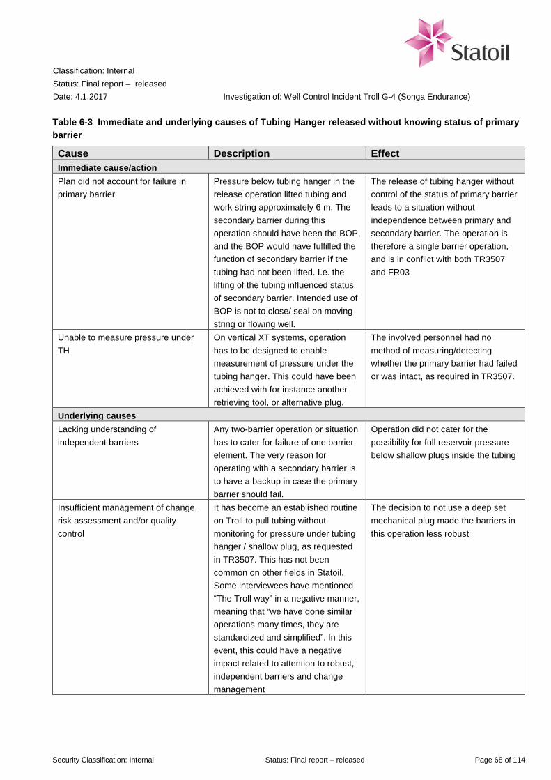
Classification: Internal Status: Final report – released Date: 4.1.2017
Investigation of: Well Control Incident Troll G-4 (Songa Endurance)
Security Classification: Internal Status: Final report – released Page 68 of 114
Table 6-3 Immediate and underlying causes of Tubing Hanger released without knowing status of primary barrier
Cause Description Effect Immediate cause/action Plan did not account for failure in primary barrier
Pressure below tubing hanger in the release operation lifted tubing and work string approximately 6 m. The secondary barrier during this operation should have been the BOP, and the BOP would have fulfilled the function of secondary barrier if the tubing had not been lifted. I.e. the lifting of the tubing influenced status of secondary barrier. Intended use of BOP is not to close/ seal on moving string or flowing well.
The release of tubing hanger without control of the status of primary barrier leads to a situation without independence between primary and secondary barrier. The operation is therefore a single barrier operation, and is in conflict with both TR3507 and FR03
Unable to measure pressure under TH
On vertical XT systems, operation has to be designed to enable measurement of pressure under the tubing hanger. This could have been achieved with for instance another retrieving tool, or alternative plug.
The involved personnel had no method of measuring/detecting whether the primary barrier had failed or was intact, as required in TR3507.
Underlying causes Lacking understanding of independent barriers
Any two-barrier operation or situation has to cater for failure of one barrier element. The very reason for operating with a secondary barrier is to have a backup in case the primary barrier should fail.
Operation did not cater for the possibility for full reservoir pressure below shallow plugs inside the tubing
Insufficient management of change, risk assessment and/or quality control
It has become an established routine on Troll to pull tubing without monitoring for pressure under tubing hanger / shallow plug, as requested in TR3507. This has not been common on other fields in Statoil. Some interviewees have mentioned “The Troll way” in a negative manner, meaning that “we have done similar operations many times, they are standardized and simplified”. In this event, this could have a negative impact related to attention to robust, independent barriers and change management
The decision to not use a deep set mechanical plug made the barriers in this operation less robust

Classification: Internal Status: Final report – released Date: 4.1.2017
Investigation of: Well Control Incident Troll G-4 (Songa Endurance)
Security Classification: Internal Status: Final report – released Page 69 of 114
6.4 Causes linked to HC leak ~50 kg/sec until Annular Preventer was closed

Classification: Internal Status: Final report – released Date: 4.1.2017
Investigation of: Well Control Incident Troll G-4 (Songa Endurance)
Security Classification: Internal Status: Final report – released Page 70 of 114
Table 6-4 Immediate and underlying causes of HC gas leak ~50 kg/sec until Annular Preventer was closed
Cause Description Effect Immediate cause/action Annular preventer not closed due to late change in DOP 090
The next to last revision of DOP 090 specified that the annular preventer should be closed with reduced pressure due to risk for gas under the tubing hanger, see App I This has been a «quiet deviation» in many previous drilling operations without subsequent update of the Master DOP. Not closing the AP was considered to be low risk as it had been done several times before without any consequences
It is considered likely that the consequences of the incident had been reduced if the annular preventer had been closed with reduced pressure before releasing the tubing hanger
Underlying causes Risk of lifting tubing hanger from seal area
The drill string was to be lifted no more than 75 mm in order not to lift the tubing hanger out of the seal area in the wellhead. With the annular preventer closed, even partially (with reduced hydraulic pressure), this lifting operation would be difficult to control
The decision to have the annular preventer fully opened, and instead close it later in the operation, was made the evening before the operation was carried out, see App I
Difficult to control lift of sleeve max 75 mm with annular preventer closed
Friction between a closed annular preventer and the drill string would make it harder to control small movements of the drill string, particularly on a semi-submersible rig
To achieve better control during the short lifting distance, it was recommended by GE Oil & Gas personnel to not close the annular preventer until after this lifting operation was carried out
Did not see risk for gas under tubing hanger
As shown in Table 6-5 on page 73, experience in the last five P&A operations on Troll were little or no gas when pulling the tubing hanger. The Troll Main Activity Program for P&A (/3/ section 4.3.8) also mentions that there could be small amounts of gas (H2S, CO or hydrocarbons).
When the risk of opening the barrier valves in the well had not been identified, none in the team assumed more than small amounts of gas under the tubing hanger The plan was revised to close the annular preventer at the stage where the upper completion was to be pulled up

Classification: Internal Status: Final report – released Date: 4.1.2017
Investigation of: Well Control Incident Troll G-4 (Songa Endurance)
Security Classification: Internal Status: Final report – released Page 71 of 114
Cause Description Effect Not clarified with Songa tool pusher or Statoil onshore
The final version of the DOP was signed by Songa junior tool pusher (planner), senior tool pusher and approved by Statoil drilling supervisor, but the first two of them were not involved in the discussion to change the DOP
The decision to make a significant change to the DOP was made by Statoil engineers and drilling supervisor, without clarifying the change with Songa Senior tool pusher or Statoil’s Drilling Superintendent.
Insufficient management of change, risk assessment and/or quality control
DOP 090 was sent to the rig when the procedure was 80 % complete. The remaining work is linked to operational rig specific changes On the front page of the DOP it is noted under “Administration offshore” that the DOP shall be “Signed by the TP (tool pusher) and Statoil Drilling Supervisor and handed out 1 day ahead of operation start”. In this case the DOP was revised at 21:18 on 14 October 2016, and the signed copy handed out to driller when the morning shift started on 15 October 2016
The change to remove a risk “Gas below TH” should have been noted as a revision
Figure 6-2 Annular preventer schematic diagram (Illustration: Cameron)
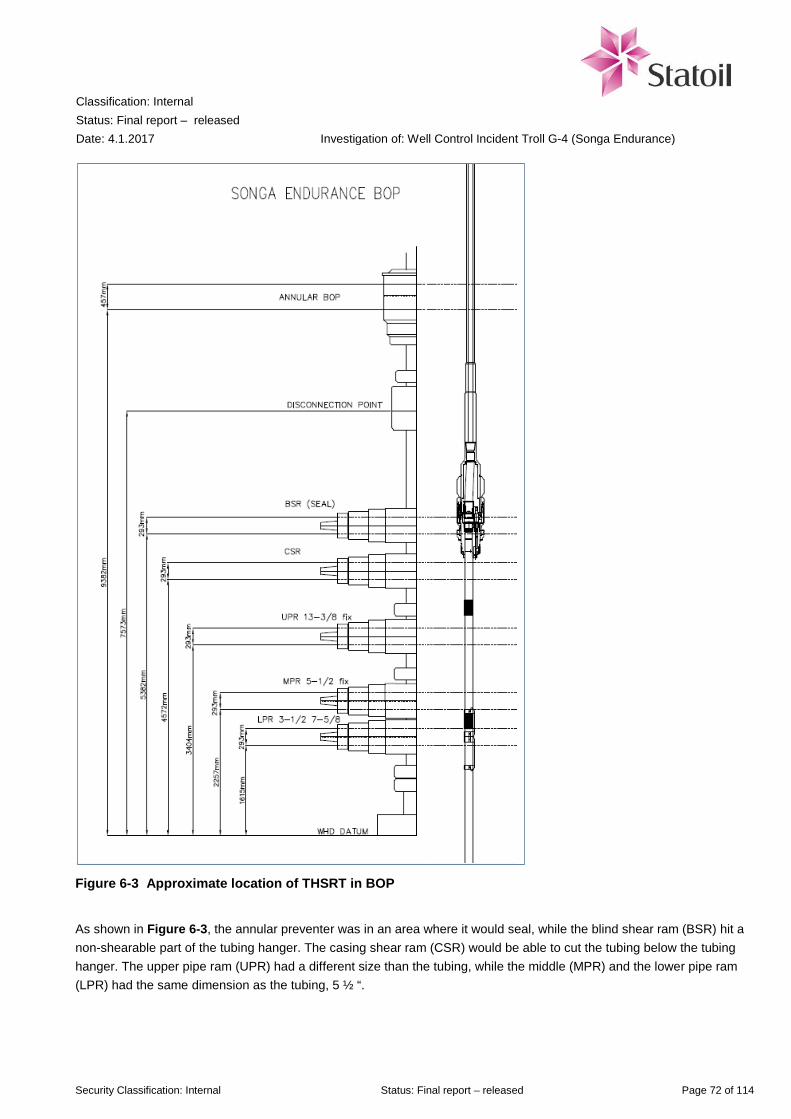
Classification: Internal Status: Final report – released Date: 4.1.2017
Investigation of: Well Control Incident Troll G-4 (Songa Endurance)
Security Classification: Internal Status: Final report – released Page 72 of 114
Figure 6-3 Approximate location of THSRT in BOP
As shown in Figure 6-3, the annular preventer was in an area where it would seal, while the blind shear ram (BSR) hit a non-shearable part of the tubing hanger. The casing shear ram (CSR) would be able to cut the tubing below the tubing hanger. The upper pipe ram (UPR) had a different size than the tubing, while the middle (MPR) and the lower pipe ram (LPR) had the same dimension as the tubing, 5 ½ “.

Classification: Internal Status: Final report – released Date: 4.1.2017
Investigation of: Well Control Incident Troll G-4 (Songa Endurance)
Security Classification: Internal Status: Final report – released Page 73 of 114
6.4.1 Previous P&A operations on Troll
In order to review common practice for P&A operations for Vetco wells on Troll, Daily Drilling Reports (DBR) information from some of the most recent West Venture operations has been reviewed. The following can be concluded:
• The reservoir has been bullheaded through tubing with mud • Deep set plug has been used as the primary barrier against the reservoir • The BOP (Annular Preventer) has not been closed before unlatching the tubing hanger. It has been closed at a
later stage after pulling tubing hanger free, or even after pulling tubing hanger above BOP before circulating the annulus
• Only minor amount of gas in mud has been observed during circulation of annulus
Table 6-5 Previous experience from P & A-operations at Troll Field
Well Date Prepare well Pull tubing hanger Gas observations 31/2-F-6 BY1H 27.05.2015 Well bullheaded with
1.08 sg Perflow. Deep plug set at 1586 m. Cut tubing at 1557 m. Set shallow plug at 427 m. Set plug in annulus bore.
Tested BOP WH connector to 160 bar. M/U THSRT with 3.5 turns. Unlatch TH with 18 t OP. M/U THSRT with 8 turns. Pull TH free with 20 t OP. Pull 15 m. Closed MPR and circulated via choke.
Recorded max 3.1% gas in mud.
31/2-D-5 AH 16.03.2015 Well bullheaded with 1.08 sg Perflow. Punch tubing at 1728 m. Deep plug set at 1819 m. Set shallow plug at 409 m.
Tested BOP WH connector to 160 bar. M/U THSRT with 4.5 turn. Pulled TH free with 113 t. Closed annular and circulated via choke.
25% LEL HC gas in shaker room on rig sensor. 20% CO measured by portable sensor on shakers. Recorded max 4.82% gas in mud.
31/2-F-1 BY1H 12.11.2014 Well bullheaded with 1.12 sg mud. Deep plug set at 1675 m. Cut tubing at 1646 m. Set shallow plug at 418 m. Set plug in annulus bore.
Tested BOP WH connector to 160 bar. M/U THSRT with 3 turn. Unlatch TH with 18 t OP. M/U THSRT with 4 turn. Closed annular and pull TH free with 30 t OP. Circulated via choke
No gas reported.
31/2-G-1 BY1H 28.07.2014 Well bullheaded with 1.12 sg mud. Deep plug set at 2088 m. Cut tubing at 2064 m. Set shallow plug at 421 m. Set plug in annulus bore.
Tested BOP WH connector to 160 bar. M/U THSRT with 4 turn. Released TH with 4 turn. Pulled TH above BOP. Closed annular and circulated via choke.
Observed max 5% gas in mud.
31/2-E-6 DY1H 13.03.2014 Well bullheaded with 1.12 sg mud. Punch tubing at 1481 m. Deep plug set at 1812 m. Set shallow plug at 381 m.
M/U THSRT with 2.5 turn. Unlatch TH with 18 t OP. Pull TH free with 160 t. Pull TH above annular. Closed annular. Not able to circ. Pull out, L/D TH, RIH on 5 1/2” DP. Circulate.
No gas reported.

Classification: Internal Status: Final report – released Date: 4.1.2017
Investigation of: Well Control Incident Troll G-4 (Songa Endurance)
Security Classification: Internal Status: Final report – released Page 74 of 114
7 Work processes, requirements and barriers
7.1 Work processes and requirements
In this section critical tasks that contributed to the incident are related to work processes in the management system and other relevant requirements. Both deviations from the requirements and inadequate requirements/processes are addressed. Relevant requirements are described in Table 7-1. The term "deviation" is defined according to Statoil’s governing system ARIS as departure from the originally specified requirements in governing documentation prior to realisation. Some of the most relevant work processes and workflows for a detailed planning and execution of a permanent P&A operation are shown in App F.
Table 7-1 Status work processes and requirements
No Work process/
requirement Reference to
requirements/ information element
Status Causes
1
FR03 Drilling and well technology (D&W)
Fundamentals (Excerpts) 1. Drilling and well shall have a capable organization for efficient planning and execution, and risk management. 3. Technical, operational and organizational barriers shall be established, monitored and maintained to ensure that no single failure can escalate into an unacceptable situation.
Weaknesses The planning of G-4 did not manage to see the risks involved in choosing an unproven method for barrier. The Troll Field teams have over time developed different operational practice than what is used by the rest of the company
Section 6.1 There was available knowledge within Troll unit and in the Main Activity program for P&A operations on Troll that could have led to identification of the risk related to using FCVs/GLV as primary barrier on VXT, but this knowledge was not drawn upon
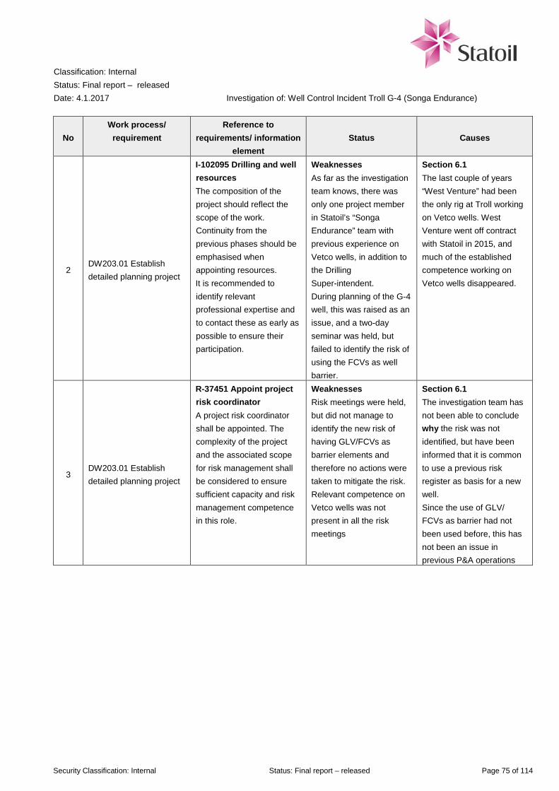
Classification: Internal Status: Final report – released Date: 4.1.2017
Investigation of: Well Control Incident Troll G-4 (Songa Endurance)
Security Classification: Internal Status: Final report – released Page 75 of 114
No Work process/
requirement Reference to
requirements/ information element
Status Causes
2 DW203.01 Establish detailed planning project
I-102095 Drilling and well resources The composition of the project should reflect the scope of the work. Continuity from the previous phases should be emphasised when appointing resources. It is recommended to identify relevant professional expertise and to contact these as early as possible to ensure their participation.
Weaknesses As far as the investigation team knows, there was only one project member in Statoil’s “Songa Endurance” team with previous experience on Vetco wells, in addition to the Drilling Super-intendent. During planning of the G-4 well, this was raised as an issue, and a two-day seminar was held, but failed to identify the risk of using the FCVs as well barrier.
Section 6.1 The last couple of years “West Venture” had been the only rig at Troll working on Vetco wells. West Venture went off contract with Statoil in 2015, and much of the established competence working on Vetco wells disappeared.
3 DW203.01 Establish detailed planning project
R-37451 Appoint project risk coordinator A project risk coordinator shall be appointed. The complexity of the project and the associated scope for risk management shall be considered to ensure sufficient capacity and risk management competence in this role.
Weaknesses Risk meetings were held, but did not manage to identify the new risk of having GLV/FCVs as barrier elements and therefore no actions were taken to mitigate the risk. Relevant competence on Vetco wells was not present in all the risk meetings
Section 6.1 The investigation team has not been able to conclude why the risk was not identified, but have been informed that it is common to use a previous risk register as basis for a new well. Since the use of GLV/ FCVs as barrier had not been used before, this has not been an issue in previous P&A operations
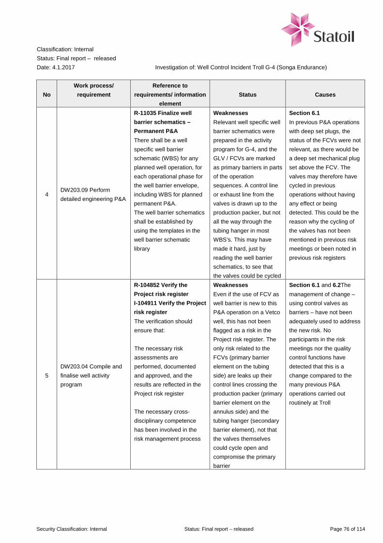
Classification: Internal Status: Final report – released Date: 4.1.2017
Investigation of: Well Control Incident Troll G-4 (Songa Endurance)
Security Classification: Internal Status: Final report – released Page 76 of 114
No Work process/
requirement Reference to
requirements/ information element
Status Causes
4 DW203.09 Perform detailed engineering P&A
R-11035 Finalize well barrier schematics – Permanent P&A There shall be a well specific well barrier schematic (WBS) for any planned well operation, for each operational phase for the well barrier envelope, including WBS for planned permanent P&A. The well barrier schematics shall be established by using the templates in the well barrier schematic library
Weaknesses Relevant well specific well barrier schematics were prepared in the activity program for G-4, and the GLV / FCVs are marked as primary barriers in parts of the operation sequences. A control line or exhaust line from the valves is drawn up to the production packer, but not all the way through the tubing hanger in most WBS’s. This may have made it hard, just by reading the well barrier schematics, to see that the valves could be cycled
Section 6.1 In previous P&A operations with deep set plugs, the status of the FCVs were not relevant, as there would be a deep set mechanical plug set above the FCV. The valves may therefore have cycled in previous operations without having any effect or being detected. This could be the reason why the cycling of the valves has not been mentioned in previous risk meetings or been noted in previous risk registers
5 DW203.04 Compile and finalise well activity program
R-104852 Verify the Project risk register I-104911 Verify the Project risk register The verification should ensure that: The necessary risk assessments are performed, documented and approved, and the results are reflected in the Project risk register The necessary cross-disciplinary competence has been involved in the risk management process
Weaknesses Even if the use of FCV as well barrier is new to this P&A operation on a Vetco well, this has not been flagged as a risk in the Project risk register. The only risk related to the FCVs (primary barrier element on the tubing side) are leaks up their control lines crossing the production packer (primary barrier element on the annulus side) and the tubing hanger (secondary barrier element), not that the valves themselves could cycle open and compromise the primary barrier
Section 6.1 and 6.2The management of change – using control valves as barriers – have not been adequately used to address the new risk. No participants in the risk meetings nor the quality control functions have detected that this is a change compared to the many previous P&A operations carried out routinely at Troll
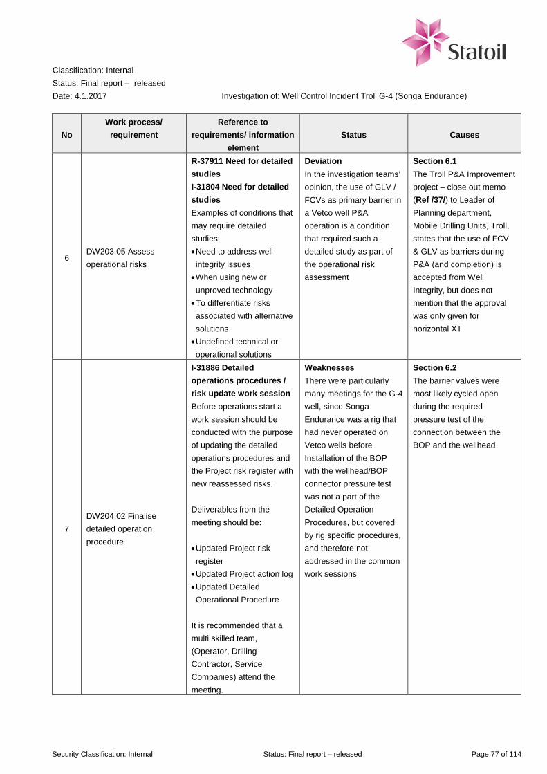
Classification: Internal Status: Final report – released Date: 4.1.2017
Investigation of: Well Control Incident Troll G-4 (Songa Endurance)
Security Classification: Internal Status: Final report – released Page 77 of 114
No Work process/
requirement Reference to
requirements/ information element
Status Causes
6 DW203.05 Assess operational risks
R-37911 Need for detailed studies I-31804 Need for detailed studies Examples of conditions that may require detailed studies: • Need to address well integrity issues • When using new or unproved technology • To differentiate risks associated with alternative solutions • Undefined technical or operational solutions
Deviation In the investigation teams’ opinion, the use of GLV / FCVs as primary barrier in a Vetco well P&A operation is a condition that required such a detailed study as part of the operational risk assessment
Section 6.1 The Troll P&A Improvement project – close out memo (Ref /37/) to Leader of Planning department, Mobile Drilling Units, Troll, states that the use of FCV & GLV as barriers during P&A (and completion) is accepted from Well Integrity, but does not mention that the approval was only given for horizontal XT
7 DW204.02 Finalise detailed operation procedure
I-31886 Detailed operations procedures / risk update work session Before operations start a work session should be conducted with the purpose of updating the detailed operations procedures and the Project risk register with new reassessed risks. Deliverables from the meeting should be: • Updated Project risk register • Updated Project action log • Updated Detailed Operational Procedure
It is recommended that a multi skilled team, (Operator, Drilling Contractor, Service Companies) attend the meeting.
Weaknesses There were particularly many meetings for the G-4 well, since Songa Endurance was a rig that had never operated on Vetco wells before Installation of the BOP with the wellhead/BOP connector pressure test was not a part of the Detailed Operation Procedures, but covered by rig specific procedures, and therefore not addressed in the common work sessions
Section 6.2 The barrier valves were most likely cycled open during the required pressure test of the connection between the BOP and the wellhead

Classification: Internal Status: Final report – released Date: 4.1.2017
Investigation of: Well Control Incident Troll G-4 (Songa Endurance)
Security Classification: Internal Status: Final report – released Page 78 of 114
No Work process/
requirement Reference to
requirements/ information element
Status Causes
8 DW204.02 Finalise detailed operation procedure
R-100927 Detailed operations procedures review The detailed operation procedures including risks shall be reviewed and updated in collaboration with rig site and office site I-102093 Detailed operations procedures review Recommended participation for the review of the detailed operations procedure: • Drilling superintendent • Lead engineer • Programme engineer • Operations geologist (PP&A) • Personnel responsible for performance management • Drilling supervisor • Contractors tool pusher • Project risk coordinator • Relevant service contractors • HSE&Q engineer • Relevant PETEC personnel • Subsea engineer Deliverables from the meeting should be: • Updated Project risk register • Updated Project action log • Finalised detailed operations procedures including risk descriptions
Deviation The final Detailed Operation Procedure (DOP) 090 for pulling the tubing hanger was not subject to a common meeting with onshore / offshore / supplier. The risk “Gas under TH” with the action “Close annular preventer” was removed from the DOP marked “FINAL” without noting this as a change The DOP was signed and handed out at the start of morning shift 15 October 2016, not the day before as stated on the front page of the DOP The change, where a risk was removed from the DOP, was not discussed with Songa Senior Tool Pusher or Statoil Drilling Superintendent, see App I
Section 6.4

Classification: Internal Status: Final report – released Date: 4.1.2017
Investigation of: Well Control Incident Troll G-4 (Songa Endurance)
Security Classification: Internal Status: Final report – released Page 79 of 114
7.2 Barriers
A barrier is defined as a technical, operational or organisational measure that could have either stopped the chain of events before the incident occurred, or reduced the consequences of the incident. This barrier analysis includes relevant risk-reducing measures that were, or should have been, planned with performance requirements and follow-up, and that are established to reduce the probability for or the consequence of this type of incidents. In this context barriers may be missing, broken, or remain intact. Broken/weak barriers are barriers that should/could have prevented or limited the incident if they had been fully functioning. This means that if the failure of the barrier had not occurred, the incident or its consequences would probably not have happened. Missing barriers are barriers that were not established but which could have prevented or limited the consequences of the incident if they had been in place. Intact barriers are barriers that worked as intended and thus stopped or limited the incident. Evaluation of status for the relevant barriers is described in Table 7-2.
Table 7-2 Barrier status
No Barrier element Reference to requirement /
performance standard Barrier status Causes
1 Establishing of project team
DW203.01 Weak barrier The project team did not have sufficient competence and experience regarding the Vetco well type on G-4
2 Risk identification in detailed planning
DW203.05 Weak barrier The risk of applying a new well barrier not previously tested in P&A of Vetco wells (FCV/GLV) was not treated with sufficient detail
3 Risk identification in execution
TR2385 B.3.2 item 6 (Ref /13/) The valve shall be documented to not shift position after it is put in closed position (being as a result of thermal or other erroneous operation through the pressure tubes)
Broken The FCV and GLV were cycled from fully closed to fully open during a connection test between the BOP and the wellhead, and could also have cycled for other reasons

Classification: Internal Status: Final report – released Date: 4.1.2017
Investigation of: Well Control Incident Troll G-4 (Songa Endurance)
Security Classification: Internal Status: Final report – released Page 80 of 114
No Barrier element Reference to requirement /
performance standard Barrier status Causes
4 Well barrier requirement: Two independent barriers
TR3507 - 2. Well Integrity fundamentals A well shall be designed to have two defined independent well barriers without common barrier elements. The actual position and status of the barriers or barrier elements shall be known at all times. Scenarios with dependant or common barrier elements during construction, and other critical barrier failure scenarios, shall be covered in the Risk Evaluation
Broken Status of primary barrier was unknown before the incident, and plan did not account for failure in primary barrier
Well control incident 5 Red zone
Songa Offshore procedure Intact barrier Parts of the drill floor is
defined as “red zone”. Unless documented in a risk analysis, the red zone is unmanned when equipment is in motion
6 Gas detection PS 3 in TR1055 (Ref /12/)
Intact barrier Gas detectors on main deck and on the drill floor detected gas, and gave automatic predefined actions according to Cause&Effect (Ref /7/)
7 Ignition source control PS 6 in TR1055 (Ref /12/)
Intact barrier Non-Ex proof equipment was automatically disconnected in areas where gas had been detected
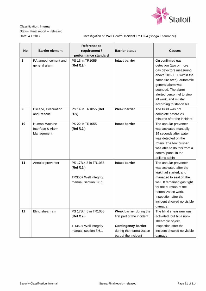
Classification: Internal Status: Final report – released Date: 4.1.2017
Investigation of: Well Control Incident Troll G-4 (Songa Endurance)
Security Classification: Internal Status: Final report – released Page 81 of 114
No Barrier element Reference to requirement /
performance standard Barrier status Causes
8 PA announcement and general alarm
PS 13 in TR1055 (Ref /12/)
Intact barrier On confirmed gas detection (two or more gas detectors measuring above 20% LEL within the same fire area), automatic general alarm was sounded. The alarm alerted personnel to stop all work, and muster according to station bill
9 Escape, Evacuation and Rescue
PS 14 in TR1055 (Ref /12/)
Weak barrier The POB was not complete before 28 minutes after the incident
10 Human Machine Interface & Alarm Management
PS 22 in TR1055 (Ref /12/)
Intact barrier The annular preventer was activated manually 19 seconds after water was detected on the rotary. The tool pusher was able to do this from a control panel in the driller’s cabin
11 Annular preventer PS 17B.4.5 in TR1055 (Ref /12/) TR3507 Well integrity manual, section 3.6.1
Intact barrier
The annular preventer was activated after the leak had started, and managed to seal off the well. It remained gas tight for the duration of the normalization work. Inspection after the incident showed no visible damage
12 Blind shear ram PS 17B.4.5 in TR1055 (Ref /12/) TR3507 Well integrity manual, section 3.6.1
Weak barrier during the first part of the incident Contingency barrier during the normalization part of the incident
The blind shear ram was, activated, but hit a non-shearable object. Inspection after the incident showed no visible damage
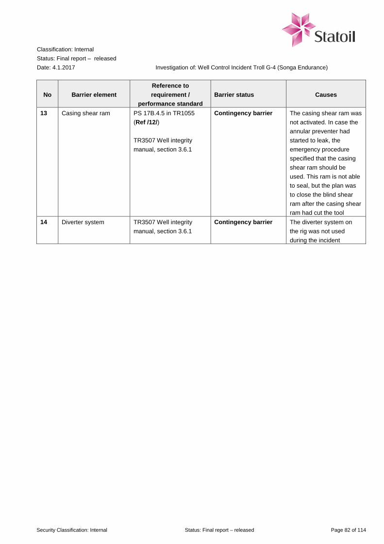
Classification: Internal Status: Final report – released Date: 4.1.2017
Investigation of: Well Control Incident Troll G-4 (Songa Endurance)
Security Classification: Internal Status: Final report – released Page 82 of 114
No Barrier element Reference to requirement /
performance standard Barrier status Causes
13 Casing shear ram PS 17B.4.5 in TR1055 (Ref /12/) TR3507 Well integrity manual, section 3.6.1
Contingency barrier The casing shear ram was not activated. In case the annular preventer had started to leak, the emergency procedure specified that the casing shear ram should be used. This ram is not able to seal, but the plan was to close the blind shear ram after the casing shear ram had cut the tool
14 Diverter system TR3507 Well integrity manual, section 3.6.1
Contingency barrier The diverter system on the rig was not used during the incident
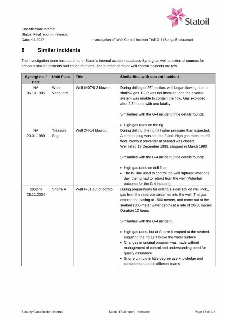
Classification: Internal Status: Final report – released Date: 4.1.2017
Investigation of: Well Control Incident Troll G-4 (Songa Endurance)
Security Classification: Internal Status: Final report – released Page 83 of 114
8 Similar incidents
The investigation team has searched in Statoil’s internal accident database Synergi as well as external sources for previous similar incidents and cause relations. The number of major well control incidents are few.
Synergi no. / Date
Unit/ Plant Title Similarities with current incident
NA 06.10.1985
West Vanguard
Well 6407/6-2 blowout During drilling of 26” section, well began flowing due to shallow gas. BOP was not installed, and the diverter system was unable to contain the flow. Gas exploded after 2.5 hours, with one fatality Similarities with the G-4 incident (little details found): • High gas rates on the rig
NA 20.01.1989
Treasure Saga
Well 2/4-14 blowout During drilling, the rig hit higher pressure than expected. A cement plug was set, but failed. High gas rates on drill floor, blowout preventer at seabed was closed. Well killed 13 December 1989, plugged in March 1990 Similarities with the G-4 incident (little details found): • High gas rates on drill floor • The kill line used to control the well ruptured after one
day, the rig had to retract from the well (Potential outcome for the G-4 incident)
285274 28.11.2004
Snorre A Well P-31 out of control During preparations for drilling a sidetrack on well P-31, gas from the reservoir streamed into the well. The gas entered the casing at 1500 meters, and came out at the seabed (300-meter water depth) at a rate of 20-30 kg/sec. Duration 12 hours Similarities with the G-4 incident: • High gas rates, but at Snorre it erupted at the seabed,
engulfing the rig as it broke the water surface • Changes in original program was made without
management of control and understanding need for quality assurance
• Snorre unit did in little degree use knowledge and competence across different teams

Classification: Internal Status: Final report – released Date: 4.1.2017
Investigation of: Well Control Incident Troll G-4 (Songa Endurance)
Security Classification: Internal Status: Final report – released Page 84 of 114
Synergi no. / Date
Unit/ Plant Title Similarities with current incident
NA 20.04.2010
Deepwater Horizon
Mississippi Canyon, block 252 blowout
Un-normal pressure in drill pipe after cement job. BOP was opened, seawater and mud came up through rotary. Gas was sucked into generators, leading to over-speeding and failure. The gas was ignited causing 11 fatalities. The rig sank, and oil flowed from the well for 87 days before successful plugging Similarities with the G-4 incident: • High rate of gas leaking to drill floor • Annular preventer used to control a flowing well, but in
this case the annular failed 1156436
19.05.2010 Gullfaks C Mud loss and influx in
well C-6 A Drilling with very small window (little difference between formation strength and pore pressure). Gas in shaker. Long period before barriers were re-established Three of the four main learning elements listed for this incident (Ref /38/) are relevant for the G-4 well: • Changes in drilling programme not documented and
formally approved. Inadequate assessment of common barrier element
• Lack of follow-up and monitoring of pressure in the C annulus
• Hole in casing. Use of common barrier element, leading to dependence between primary and secondary barrier

Classification: Internal Status: Final report – released Date: 4.1.2017
Investigation of: Well Control Incident Troll G-4 (Songa Endurance)
Security Classification: Internal Status: Final report – released Page 85 of 114
9 Recommendations for learning
Recommendations described in this chapter are given with the intent of preventing similar incidents to happen in the future and contribute to the overall improvement of HSE performance. The recommendations are based on the identified causes of the incident. It should be noted that there may be other relevant actions than those recommended in this report.
9.1 Immediate actions performed after the incident
On Friday 04 November, the investigation team suggested the following immediate action to the commissioning entity:
The following Monday, 7 November, Head of Drilling & Well, Mobile Units sent this to all managers in the Mobile Units division (translated by investigation team):
In addition, the investigation team has been informed that following the well control incident on G-4, an action list has been developed in cooperation between D&W Managers and Senior Vice President TPD D&W Operations. The actions in this list has also been entered in the Ambition to Action board in TPD D&W Mobile Units, and will be linked to each D&W Manager.
When pulling tubing hanger on vertical systems, it shall be monitored for pressure below shallow set plug before the tubing hanger is released. This to avoid the tubing being lifted up into the BOP by any pressure under the shallow plug. The monitoring shall be made, independent of the solution chosen as primary barrier, that is even if a deep set bridge plug is installed in the well.
Detailed Operation Procedure approval • All changes to DOP after “review and update” meeting shall be confirmed
and approved by Drilling Superintendent • Changes to DOP exceeding what has been agreed in the “review and
update” meeting shall be subject to risk assessment and be documented in change log
Tubing hanger/plug pulling • When pulling tubing hanger or plugs, it shall be monitored for pressure
below before tubing hanger/plug is released. This monitoring shall be made independent of the solution chosen for primary barrier, for instance deep set plug.
• If it’s not possible to monitor for pressure below / behind plug / tubing hanger / casing etc. measures must be taken to avoid outflow of gas / hydrocarbons. This will typically be to have closed BOP annular or similar, with sufficient weight on the string
Please distribute this to all relevant in own unit, onshore and offshore

Classification: Internal Status: Final report – released Date: 4.1.2017
Investigation of: Well Control Incident Troll G-4 (Songa Endurance)
Security Classification: Internal Status: Final report – released Page 86 of 114
Songa Offshore Songa Offshore has updated the Station Bill on all their rigs to have Tool Pusher off duty muster at the Emergency Response Center, while Tool Pusher on duty muster at drill floor.
9.2 Learning and recommendations
Learning and needs of improvement points to what the investigation shows should be improved or enhanced while actions are the specific proposals describing how this can be realized. It should be noted that there may be other steps than those described below.
Table 9-1 Recommended actions
No Learning and improvement
needs Reason/ Barrier-reference Recommended actions Target group
1
Plan to improve change management and risk identification in drilling projects
Cause 6.1, 6.2, 6.3 and 6.4 1: Establish a project to go further in examining ways to improve the management of change and risk identification in drilling projects. The project should also do a deeper cause analysis regarding why there were shortcomings in this and other well control incidents
TPD D&W
2 Improved management of change
Cause 6.1 2A: Awareness of balance between team diversity and field specific competence when establishing new teams
TPD D&W
Cause 6.1 and 6.2 2B: Must elaborate on potential consequences, i.e. impact and risk, of changes that are made
TPD D&W
Cause 6.1 and 6.2 2C: Establish system for competence mapping of Engineers in D&W, include well integrity and control, and DISP request process in more detail
TPD D&W
Cause 6.4 2D: Establish clear criteria for the DOP change process, and responsibilities between
TPD D&W
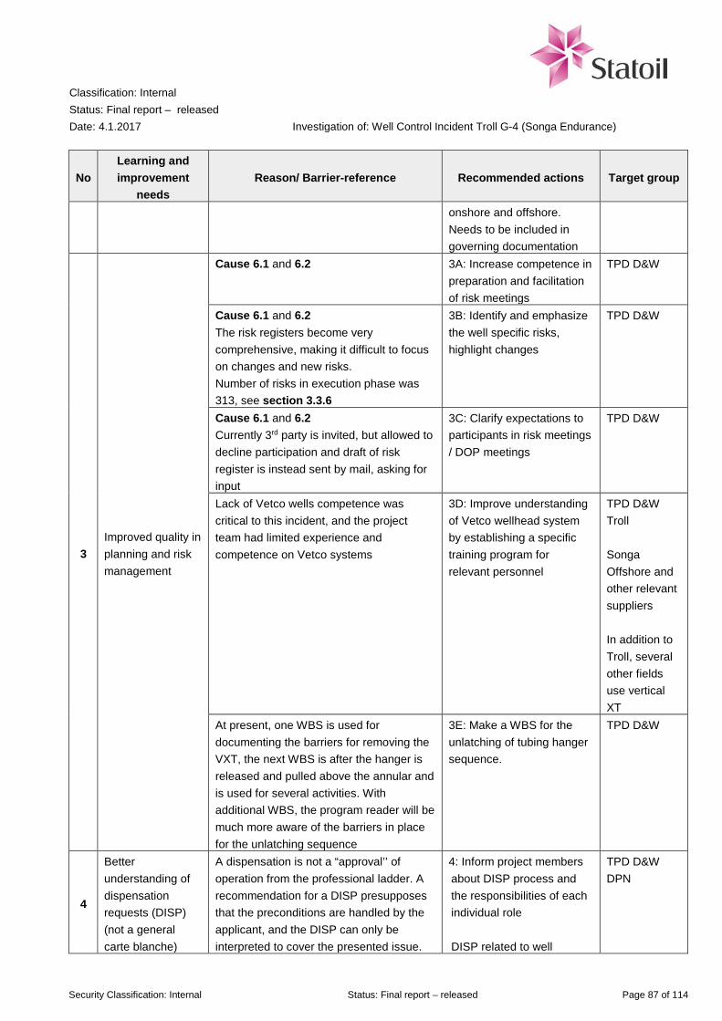
Classification: Internal Status: Final report – released Date: 4.1.2017
Investigation of: Well Control Incident Troll G-4 (Songa Endurance)
Security Classification: Internal Status: Final report – released Page 87 of 114
No Learning and improvement
needs Reason/ Barrier-reference Recommended actions Target group
onshore and offshore. Needs to be included in governing documentation
3 Improved quality in planning and risk management
Cause 6.1 and 6.2 3A: Increase competence in preparation and facilitation of risk meetings
TPD D&W
Cause 6.1 and 6.2 The risk registers become very comprehensive, making it difficult to focus on changes and new risks. Number of risks in execution phase was 313, see section 3.3.6
3B: Identify and emphasize the well specific risks, highlight changes
TPD D&W
Cause 6.1 and 6.2 Currently 3rd party is invited, but allowed to decline participation and draft of risk register is instead sent by mail, asking for input
3C: Clarify expectations to participants in risk meetings / DOP meetings
TPD D&W
Lack of Vetco wells competence was critical to this incident, and the project team had limited experience and competence on Vetco systems
3D: Improve understanding of Vetco wellhead system by establishing a specific training program for relevant personnel
TPD D&W Troll Songa Offshore and other relevant suppliers In addition to Troll, several other fields use vertical XT
At present, one WBS is used for documenting the barriers for removing the VXT, the next WBS is after the hanger is released and pulled above the annular and is used for several activities. With additional WBS, the program reader will be much more aware of the barriers in place for the unlatching sequence
3E: Make a WBS for the unlatching of tubing hanger sequence.
TPD D&W
4
Better understanding of dispensation requests (DISP) (not a general carte blanche)
A dispensation is not a “approval’’ of operation from the professional ladder. A recommendation for a DISP presupposes that the preconditions are handled by the applicant, and the DISP can only be interpreted to cover the presented issue.
4: Inform project members about DISP process and the responsibilities of each individual role DISP related to well
TPD D&W DPN

Classification: Internal Status: Final report – released Date: 4.1.2017
Investigation of: Well Control Incident Troll G-4 (Songa Endurance)
Security Classification: Internal Status: Final report – released Page 88 of 114
No Learning and improvement
needs Reason/ Barrier-reference Recommended actions Target group
Effect on the further operation has to be included in planning. Risk is still owned by the rig team, and a DISP will not reduce the further risk assessment.
integrity shall always have a thorough risk assessment and shall be reviewed and supported by Manager D&W before sent to professional ladder for QA/QC
Review ARIS-process for DISP, including supplier involvement.
5 Increase robustness of barriers
Cause 6.1 The investigation team do not see any safe way to use flow control valves as deep set barrier on vertical wellheads. Control valves might also cycle on horizontal wellheads
5A: Consider revision of TR2385 / GL3507 regarding use of valves that can be cycled as well barrier in P&A operations. Point out the specific risk when using cyclable valves as barriers in the GL3507
TPD D&W Well Technology
5B: Recommend use of deep set plugs during P&A on VXT
TPD D&W
Cause 6.3 In this incident it was not independent barriers. When the primary barrier failed, this also the secondary barrier fail
5C: Increase understanding of the integrity of the barriers and which barriers are in place at any given time, transition of barriers, including need for independence between different barriers Operational personnel need to be aware of the barriers in the different stages of operation, must be usable on the rig as an operational tool (WBS in DOP)
TPD D&W / Songa Offshore
6 Continuous learning
Cause 6.3 Need for better understanding of risks associated with the large gas reservoir in Troll
6A: Increase knowledge of gas reservoir in Troll where the large gas cap can have high consequence in case of gas influx
TPD D&W Troll / Songa Offshore
Cause 6.4 6B: Inform D&W engineering and operational
TPD D&W

Classification: Internal Status: Final report – released Date: 4.1.2017
Investigation of: Well Control Incident Troll G-4 (Songa Endurance)
Security Classification: Internal Status: Final report – released Page 89 of 114
No Learning and improvement
needs Reason/ Barrier-reference Recommended actions Target group
Need for better understanding of BOP limitations to close on flowing wells
personnel about capabilities of BOP– need for robustness in well planning
Well Control Equipment Songa Offshore
Cause 6.4 Need for better understanding of BOP limitations to close on flowing wells
6C: Establish an industry project to review BOP robustness and limitations
TPD
Cause 6.2 Need for better understanding of well barriers
6C: Experience transfer on the consequence of cycling a valve used as a well barrier, and how they can be unintentionally cycled
TPD D&W DPN Songa Offshore
Cause 6.2 There is a general misunderstanding that “minimum operation pressure” is the lowest pressure where equipment such as the GLV and FCVs will operate or cycle. For G-4 the difference is 30 bar (actual lowest pressure where the valves operate) and 207 bar (“minimum operation pressure”)
6D: Inform about difference between “lowest pressure needed to operate” and “recommended minimum pressure used to operate”
TPD D&W DPN
Experience transfer after incidents 6E: Experience sharing with IOGP, Drilling managers’ forum, NOG, Rig owners’ association, Statoil’s Troll partners
TPD D&W
Late POB control due to personnel moving from place to place in early stage of mustering
6F: More focus on POB control and expand the training and drills with more realistic scenarios
Songa Offshore
Classification: Internal Status: Final report – released Date: 4.1.2017
Investigation of: Well Control Incident Troll G-4 (Songa Endurance)
Security Classification: Internal Status: Final report – released Page 90 of 114
10 Glossary of abbreviations and terms
AP Annular Preventer API American Petroleum Institute ATA Automatic Thruster Assist BHA Bottom Hole Assembly BOP Blow Out Preventer BSP Bottom Side Packer CBL Casing Bond Log CL Control Line DBR Daily Drilling Report (Daglig Bore Rapport) DECT Downhole Electrical Cutter Tool DHSV Down Hole Safety Valve DP Dynamic Positioning DPN Development & Production Norway, unit in Statoil D&W Drilling & Well EQDP Emergency Quick Disconnect Package FBIV Full Bore Isolation Tool FCV Flow Control Valve FG Fracture Gradient GIMAT Global Incident Management Assist Team GLV Gas Lift Valve HC Hydrocarbons HCM-A Trademark for valve manufactured by Baker Hughes HEX High Expansion Plug HMBP Hydro Mechanical Bridge Plug HPC High Pressure Cap HPCRT High Pressure Cap Running Tool HSE Health, Safety and Environment HXT Horizontal Christmas Tree ICV Inflow Control Valve IOGP International Association of Oil & Gas Producers ITC Internal Tree Cap IV Isolation Valve LEL Lower Explosion Limit LRP Lower Riser Package MCBPV Multi-Cycle Bypass Valve MD Measured Depth MEG Methyl Ethylene Glycol (anti-freeze) MSL Mean Sea Level MSP Multi setting pulling tool OWC Oil Water Contact P&A / PnA Plug and Abandonment PBR Polished Bore Receptacle PBT Production Bore Test

Classification: Internal Status: Final report – released Date: 4.1.2017
Investigation of: Well Control Incident Troll G-4 (Songa Endurance)
Security Classification: Internal Status: Final report – released Page 91 of 114
PERT Pack off Emergency Retrieval Tool PP Production Packer PSA Petroleum Safety Authority (Petroleumstilsynet – Ptil) RIH Run in Hole ROV Remotely Operating Vessel RT Running Tool SCM Subsea Control Module SG Specific Gravity SLS Single Line Switch SP Swell Packer SRT Seal Retrieval Tool SW Sea Water TCRT Tree Cap Running Tool TCT Tree Cap Test line TD Target Depth TH Tubing Hanger THERT Tubing Hanger Emergency Recovery Tool THIS Tubing Hanger Isolation Sleeve THRT Tubing Hanger Running Tool THSRT Tubing Hanger Secondary Running tool TPD Technology Projects & Drilling TR Technical requirement TRT Tree Running Tool TSP Top Set Packer TVD True Vertical Depth TWGP Troll West Gas Province TWOP Troll West Oil Province USIT Ultrasonic Image Tool USRS Ultrasonic Rotating Sub VXT Vertical Christmas Tree WI Well Intervention WOCS Work Over Control System XT Christmas Tree (Production / Injection Tree) XTBP Christmas Tree Bore Protector

Classification: Internal Status: Final report – released Date: 4.1.2017
Investigation of: Well Control Incident Troll G-4 (Songa Endurance)
Security Classification: Internal Status: Final report – released Page 92 of 114
11 References
/1/ Statoil document “Handover of wells from D&W to OMM”, Well 31/2 G-4 BY1H/BY2H, Dated 08.01.2012
/2/ Statoil document “Troll Main Activity Program for Drilling and Completion”, rev 02, approved 12.05.2015
/3/ Statoil document “Troll Main Activity Program – Plug and Abandonment and prepare sidetrack”, rev 00,
approved 27.05.2015
/4/ Statoil document no AU-EPN-D&W DBG-00681 “Permanent Plug and Abandonment Program Well 31/2-G-4
BY1H/BY2H”, rev. 0, dated 05.08.2016
/5/ Statoil document “Location specific risk and emergency preparedness review Well name: 31/2-G-4”, rev 00,
dated 15.09.2016
/6/ Statoil document “Bridging document for emergency response between Songa Offshore and Statoil”, Revision
01, Dated 09.11.2015
/7/ Songa Offshore “Cause and Effect chart for Fire & Gas”, Drawing No. 3031DA931E210, Revision 14, Dated
21-aug-2015
/8/ Songa Endurance Detailed Operation Procedure DOP 090 “Pull TH & upper completion using THSRT”,
version 19.0, modified 14.10.2016 at 21:18
/9/ Songa Endurance Detailed Operation Procedure DOP 090 “Pull TH & upper completion using THSRT”,
version 18.0, modified 14.10.2016 at 19:57
/10/ West Venture Detailed Drilling Instructions WEL-25-0030 DDI 090 “Pull TH & upper completion using THSRT”,
as done, rev. 30.03.2015
/11/ Statoil work process DW904 “Well incident and blowout response plan”, Version 1.10, Revision date 25. Aug
2016
/12/ Statoil technical requirement TR 1055 “Performance Standards for Safety Systems and Barriers - Offshore”,
Version 4.04, Valid from 2013-10-03
/13/ Statoil technical requirement TR 2385 “Well Completion Equipment”, Version 4.01, Valid from 2015-06-09
/14/ Statoil technical requirement TR 3501 “Drilling Activity”, Version 3.03, Valid from 2015-06-10
/15/ Statoil technical requirement TR 3506 “Well Incident and Blowout Preparedness”, Version 4, Valid from 2016-
07-04
/16/ Statoil technical requirement TR 3507 “Well Integrity Manual”, Version 3.04, Valid from 2016-05-18
/17/ Statoil working requirement WR1214 “Second line emergency preparedness plan”, Version 12, Valid from
2016-09-01
/18/ Statoil working requirement WR2669 “Manage dispensations for drilling and well requirements”, Version 2.01,
Valid from 2016-02-01
/19/ Statoil requirement R-24383 “SSU – Pre-defined safety and security impact categories”, Version 2.5, dated 5.
Jan. 2016
/20/ Statoil requirement R-26760 “Categorise and classify”, Version 4.2, dated 11 Mar. 2016
/21/ Statoil requirement R-105426 “Identify consequences/loss potential and register in Synergi case”, version 2.1,
dated 27 Aug 2016
/22/ Statoil guideline GL0131 “Guideline for estimating leakage rates”, Version 2.03, Valid from 2009-12-28

Classification: Internal Status: Final report – released Date: 4.1.2017
Investigation of: Well Control Incident Troll G-4 (Songa Endurance)
Security Classification: Internal Status: Final report – released Page 93 of 114
/23/ Statoil guideline GL0455 “Guidelines for categorization and classification of well incidents during well
construction / intervention”, version 2.01, valid from 2015-07-28
/24/ Statoil guideline GL0498 “Guidance for blowout scenarios”, version 1, valid from 2013-01-29
/25/ Statoil guideline GL0604 “Assess potential severity in Safety incidents under 'slightly different circumstances'”,
version 2.2, valid from 2016-07-20
/26/ Statoil guideline GL3507 “Well Integrity Guidelines”, Version 1.03, Valid from 2016-05-18
/27/ Statoil guideline GL3517 “Blowout response support doc”, Version 1, Valid from 2012-05-18
/28/ Statoil guideline GL3594 “Well control manual”, Version 1, Valid from 2012-05-18
/29/ Statoil organisation, management and control OMC05 “Technology, projects and drilling (TPD)”, version 1.05,
valid from 2016-09-27 (replaced by newer version after the incident)
/30/ Norwegian Oil and Gas No 135 “Recommended Guidelines for Classification and categorization of well control
incidents and well integrity incidents”, Revision 03, dated 2016.05.06
/31/ The National Academic Press “Macondo Well Deepwater Horizon Blowout – Lessons for improving offshore
drilling safety”, 2012, available at https://www.nap.edu/read/13273
/32/ Jan-Erik Vinnem “Offshore Risk Assessment Vol 1 – Principles, Modelling and Applications of QRA Studies”,
Springer, 3rd Edition, 2014
/33/ DNV report 2013-1513 “Miljørisikoanalyse (MRA) for Trollfeltet (Troll B og Troll C) i Nordsjøen” (Environmental
risk analysis for Troll field (Troll B and Troll C) in the North Sea), revision 00, dated 2013-11-27
/34/ GE Oil&Gas technical report SOS/TO-VGS-STH-RE-0048 “Technical report for THSRT/TH pulled from well G-
4”, Revision NC, dated 22.11.2016
/35/ Safetec report ST-10396-4 “Songa Endurance – Quantitative risk analysis”, Rev. 3.0, dated 12.08.2016
/36/ Statoil minutes of meeting “Evaluate use of FCV and GLV as barriers during P&A”, dated 29.09.2015
/37/ Statoil memo “Troll P&A improvement project – close out”, to Leader planning dept. Mobile drilling units Troll,
dated 2016-01-27
/38/ Statoil’s internal web-page “Safety investigation one-pagers – learn from experience”
/39/ Statoil dispensation request DISP 145458 “Utilizing GLV as a barrier element on well 31/2-G-4 BY1H/BY2H”,
dispensation from governing documentation “TR3507 – Well Integrity Manual offshore operations”, initiated
30.06.2016
/40/ Email from Cameron Product Line Manager to Songa Offshore “Annular / BSR closing on well bore flow”,
dated 21 November 2016
/41/ Letter from Cameron VP Engineering and Manufacturing regarding closing of annular under flowing conditions,
dated December 29, 2016
/42/ Statoil document PTT-NKG-RA 64-3 “Snorre Field Metocean Design Basis”, Rev. no 5, Rev. date 03.06.2010

Classification: Internal Status: Final report – released Date: 4.1.2017
Investigation of: Well Control Incident Troll G-4 (Songa Endurance)
Security Classification: Internal Status: Final report – released Page 94 of 114
App A Interview list
The following list shows who the investigation team has interviewed or had meetings with.
Position Company Offshore on Songa Endurance Drilling supervisor (dayshift) Statoil
Drilling supervisor (nightshift) Statoil
Planning engineer (onshore position, temporary offshore) Statoil
Subsea engineer (onshore position, temporary offshore) Statoil
Senior tool pusher Songa
Junior tool pusher Songa
Driller (dayshift) Songa
Roughneck (dayshift) Songa
Chief engineer Songa
Barge Master Songa
Offshore Installation Manager Songa Offshore Supervisor GE Oil & Gas
Onshore personnel – planning and support Manager Mobile drilling units, Troll Statoil Drilling Superintendent Songa Endurance Statoil Leading drilling engineer Statoil Leader planning dept. Mobile drilling units, Troll Statoil Rig manager Songa Endurance Songa Subsea Manager Songa Legal Advisor GE Oil & Gas Technical manager - Cased Hole Completion Baker Hughes Onshore Technical Support Baker Hughes Offshore Technical Support Baker Hughes Emergency preparedness Planning Section Chief, Emergency preparedness (Line 2) Statoil Manager Emergency preparedness (Line 2) Statoil Incident Commander, Emergency preparedness (Line 2) Songa Emergency preparedness, operations (Line 2) Songa Involved in normalisation Superintendent Drilling & Well Operations Statoil Lead Engineer Drilling & Well Operations Statoil Senior Engineer Well Operations Subsea Statoil Lead Engineer Drilling & Well Operations Statoil Leader Drilling & Well Operations (Subsurface Support Center) Statoil Leading Advisor Drilling Technology Well Integrity (Subsurface Support Center) Statoil Technical Advisor GE Oil & Gas Technical Advisor GE Oil & Gas
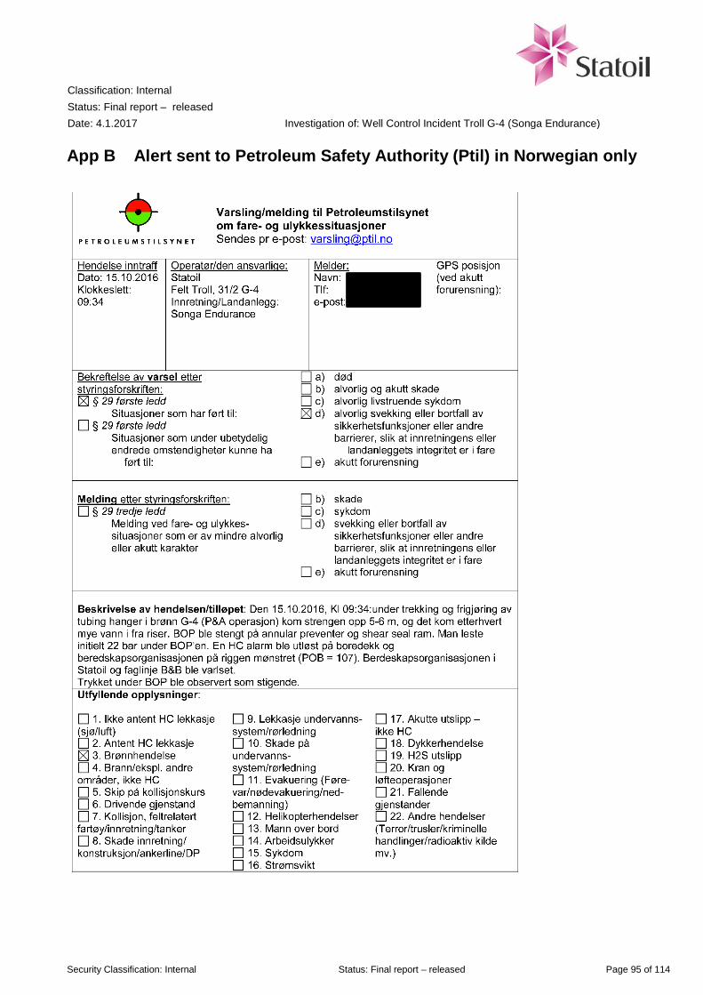
Classification: Internal Status: Final report – released Date: 4.1.2017
Investigation of: Well Control Incident Troll G-4 (Songa Endurance)
Security Classification: Internal Status: Final report – released Page 95 of 114
App B Alert sent to Petroleum Safety Authority (Ptil) in Norwegian only
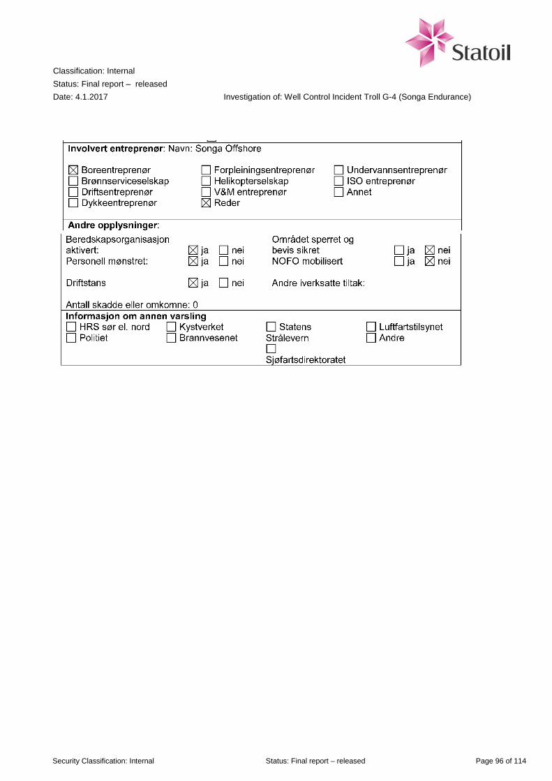
Classification: Internal Status: Final report – released Date: 4.1.2017
Investigation of: Well Control Incident Troll G-4 (Songa Endurance)
Security Classification: Internal Status: Final report – released Page 96 of 114
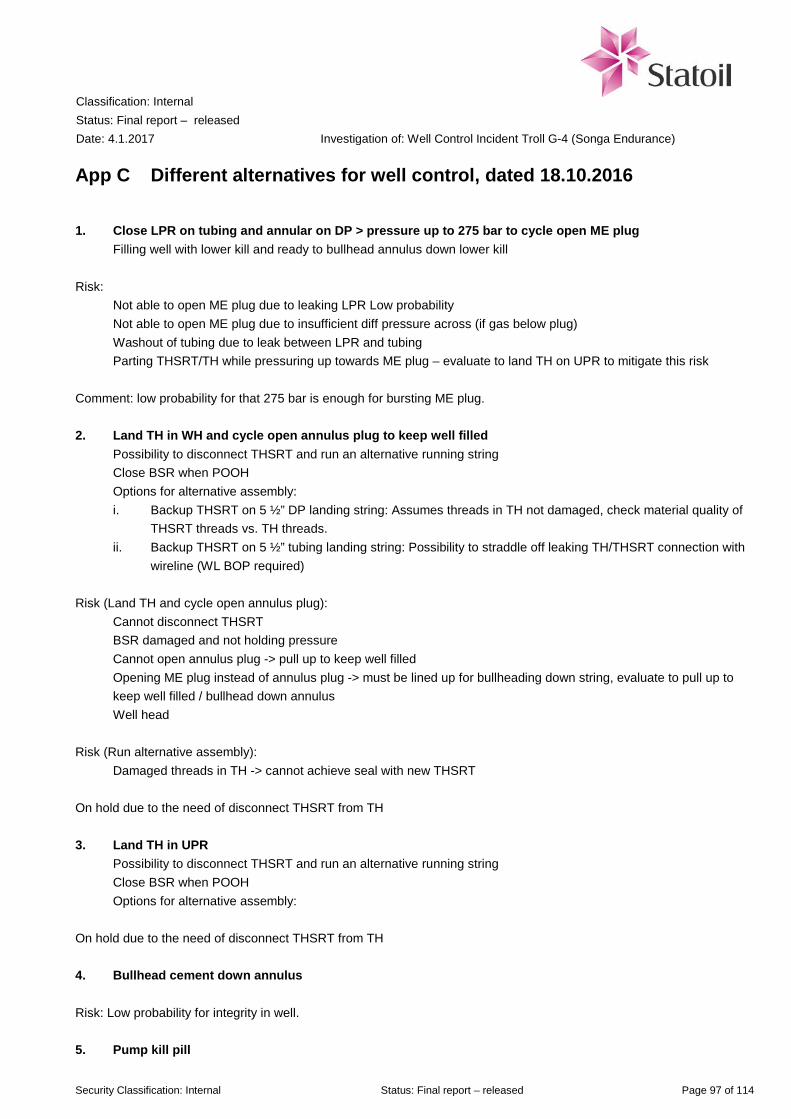
Classification: Internal Status: Final report – released Date: 4.1.2017
Investigation of: Well Control Incident Troll G-4 (Songa Endurance)
Security Classification: Internal Status: Final report – released Page 97 of 114
App C Different alternatives for well control, dated 18.10.2016
1. Close LPR on tubing and annular on DP > pressure up to 275 bar to cycle open ME plug Filling well with lower kill and ready to bullhead annulus down lower kill Risk: Not able to open ME plug due to leaking LPR Low probability Not able to open ME plug due to insufficient diff pressure across (if gas below plug) Washout of tubing due to leak between LPR and tubing Parting THSRT/TH while pressuring up towards ME plug – evaluate to land TH on UPR to mitigate this risk Comment: low probability for that 275 bar is enough for bursting ME plug. 2. Land TH in WH and cycle open annulus plug to keep well filled Possibility to disconnect THSRT and run an alternative running string Close BSR when POOH Options for alternative assembly: i. Backup THSRT on 5 ½” DP landing string: Assumes threads in TH not damaged, check material quality of
THSRT threads vs. TH threads. ii. Backup THSRT on 5 ½” tubing landing string: Possibility to straddle off leaking TH/THSRT connection with
wireline (WL BOP required) Risk (Land TH and cycle open annulus plug): Cannot disconnect THSRT BSR damaged and not holding pressure Cannot open annulus plug -> pull up to keep well filled Opening ME plug instead of annulus plug -> must be lined up for bullheading down string, evaluate to pull up to
keep well filled / bullhead down annulus Well head Risk (Run alternative assembly): Damaged threads in TH -> cannot achieve seal with new THSRT On hold due to the need of disconnect THSRT from TH 3. Land TH in UPR Possibility to disconnect THSRT and run an alternative running string Close BSR when POOH Options for alternative assembly: On hold due to the need of disconnect THSRT from TH 4. Bullhead cement down annulus Risk: Low probability for integrity in well. 5. Pump kill pill

Classification: Internal Status: Final report – released Date: 4.1.2017
Investigation of: Well Control Incident Troll G-4 (Songa Endurance)
Security Classification: Internal Status: Final report – released Page 98 of 114
to be able to circulate out gas Needs to be described more in detail 6. Land tubing hanger and open annulus plug Shear DP w/ casing shear Needs to be described more in detail Alternatives from rig. 7. WL + WLBOP + Lubricator. R/U on DP. Use shoot down tool. Risk: Ignition of gas? Not designed for purpose? 8. Cut with BSR under ME plug. Fill well w/lower kill and kill annulus after ME plug is sheared 9. Land TH in WH and cycle open annulus plug to keep well filled. Back off THSRT and 10. Run backup THSRT on 5 ½” DP 11. Run backup THSRT on 5” TBG and straddle off leakage. 12. B/O with left hand torque until one component back off in landing string 13. Straddle of THSRT and TH w/WL (- Not possible) 14. Coiled tubing operations Alternative- Task force G-4 7) Bleed and evacuate gas pull completion Alternative from SSC: 14) Hang off on LPR with casing collar Run DECT cutter and cut below hanger Pull out Run EZSV etc. on pipe Close annular to centralize Enter tubing close packer Risk: Can string rotate when we try to set ezsv? Must probably be set with hydraulic setting tool Extra force down when we bullhead. Will LPR manage that? Do we have other possibilities?
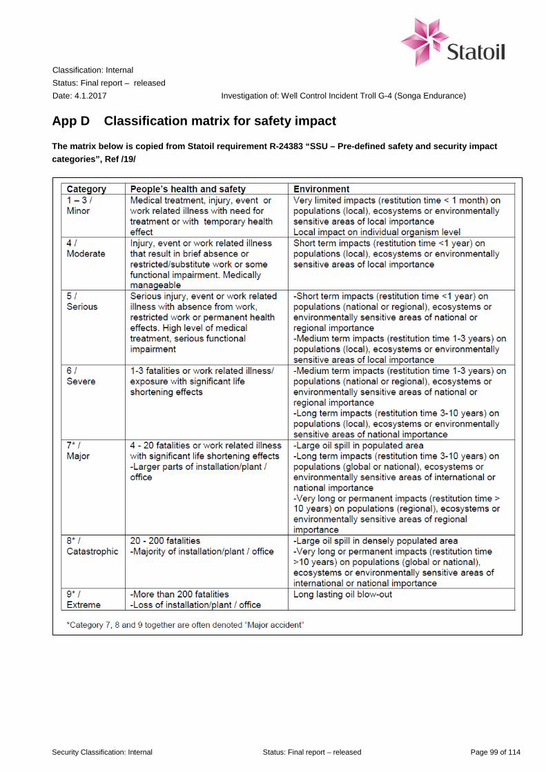
Classification: Internal Status: Final report – released Date: 4.1.2017
Investigation of: Well Control Incident Troll G-4 (Songa Endurance)
Security Classification: Internal Status: Final report – released Page 99 of 114
App D Classification matrix for safety impact
The matrix below is copied from Statoil requirement R-24383 “SSU – Pre-defined safety and security impact categories”, Ref /19/
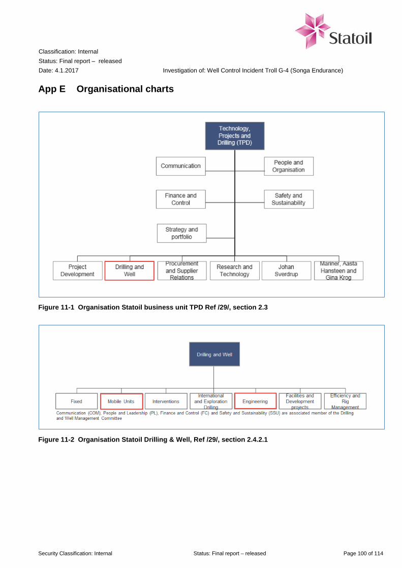
Classification: Internal Status: Final report – released Date: 4.1.2017
Investigation of: Well Control Incident Troll G-4 (Songa Endurance)
Security Classification: Internal Status: Final report – released Page 100 of 114
App E Organisational charts
Figure 11-1 Organisation Statoil business unit TPD Ref /29/, section 2.3
Figure 11-2 Organisation Statoil Drilling & Well, Ref /29/, section 2.4.2.1

Classification: Internal Status: Final report – released Date: 4.1.2017
Investigation of: Well Control Incident Troll G-4 (Songa Endurance)
Security Classification: Internal Status: Final report – released Page 101 of 114
Figure 11-3 Organisation chart for Songa Endurance offshore

Classification: Internal Status: Final report – released Date: 4.1.2017
Investigation of: Well Control Incident Troll G-4 (Songa Endurance)
Security Classification: Internal Status: Final report – released Page 102 of 114
Figure 11-4 Organisation chart Songa Offshore Operations.

Classification: Internal Status: Final report – released Date: 4.1.2017
Investigation of: Well Control Incident Troll G-4 (Songa Endurance)
Security Classification: Internal Status: Final report – released Page 103 of 114
App F Work processes for Plug & Abandonment
On the following pages, the main workflows for the process for Permanent P&A is shown, with examples of flow charts within the workflows in processes for “Plan well in detail” and “Execute operation”. In the flow charts, a warning sign denotes a requirement, while the document symbol denotes an information element.
Process DW200 Workover and permanent P&A (cut-out)
Workflow for DW203 Plan well in detail

Classification: Internal Status: Final report – released Date: 4.1.2017
Investigation of: Well Control Incident Troll G-4 (Songa Endurance)
Security Classification: Internal Status: Final report – released Page 104 of 114
Flow chart for DW203.01 Establish detailed planning project
Flow chart for DW203.05 Assess operational risks
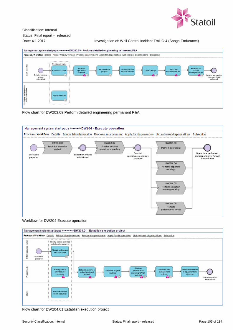
Classification: Internal Status: Final report – released Date: 4.1.2017
Investigation of: Well Control Incident Troll G-4 (Songa Endurance)
Security Classification: Internal Status: Final report – released Page 105 of 114
Flow chart for DW203.09 Perform detailed engineering permanent P&A
Workflow for DW204 Execute operation
Flow chart for DW204.01 Establish execution project

Classification: Internal Status: Final report – released Date: 4.1.2017
Investigation of: Well Control Incident Troll G-4 (Songa Endurance)
Security Classification: Internal Status: Final report – released Page 106 of 114
Flow chart for DW204.02 Finalise detailed operation procedure
Flow chart for DW204.03 Perform operation

Classification: Internal Status: Final report – released Date: 4.1.2017
Investigation of: Well Control Incident Troll G-4 (Songa Endurance)
Security Classification: Internal Status: Final report – released Page 107 of 114
App G Description of Flow Control and Gas Lift Valves
In well G-4, two hydraulically operated Flow Control Valve (FCVs) HCM-A from Baker Hughes are used. The HCM-A valve has 14 positions, of which every other is Open (100%) position. The other positions are Closed (0%) and choked positions (2%, 5% and 27%). The two FCVs are connected in series, operated by a single control line. On Vetco systems, the exhaust line (returns from each FCV operation) is bled off in a hydrocarbon-free environment above the production packer. A check valve prevents annulus fluid from contaminating the control line. A single line switch (SLS) is used to operate the FCV using only one supply line. The SLS has an internal spring loaded piston which routes flow from its inlet to one of two outlets. Every time pressure is applied through the inlet (and bled off) the SLS switches between the two outlets. This allows for alternately pressuring up the open and close ports to cycle an FCV using only one control line. The SLS piston has a metal-to-metal seal with its chamber, resulting in a small leakage rate past the piston. This is purposely designed to prevent hydraulic lock, but results in operational consequences. The SLS minimum shifting pressure is approximately 200-400 psi (14-28 bar). This low pressure means the SLS can shift with unintentional pressure spikes, declining pressure or thermal expansion. An unintentional shift of the SLS is called a “blind shift” and this is confirmed when pressure is increased expecting to get a pumped in or return volume and sees almost no volume. The solution is to bleed off below 200 psi, wait according to procedure stated time, and pressure up again. Drawings and details on the HCM-A valve is shown on the next page.

Classification: Internal Status: Final report – released Date: 4.1.2017
Investigation of: Well Control Incident Troll G-4 (Songa Endurance)
Security Classification: Internal Status: Final report – released Page 108 of 114
Inlet ports
Figure 11-5 Overview and detail of the HCM-A Flow Control Valve in well G-4

Classification: Internal Status: Final report – released Date: 4.1.2017
Investigation of: Well Control Incident Troll G-4 (Songa Endurance)
Security Classification: Internal Status: Final report – released Page 109 of 114
Figure 11-6 Shifting logic for the coupled Flow Control Valves in well G-4 (Source: Baker Hughes)
Figure 11-7 Shifting logic for the Gas Lift Valve in well G-4 (Source: Baker Hughes)

Classification: Internal Status: Final report – released Date: 4.1.2017
Investigation of: Well Control Incident Troll G-4 (Songa Endurance)
Security Classification: Internal Status: Final report – released Page 110 of 114
App H Choke Manifold line-up sketch

Classification: Internal Status: Final report – released Date: 4.1.2017
Investigation of: Well Control Incident Troll G-4 (Songa Endurance)
Security Classification: Internal Status: Final report – released Page 111 of 114
App I Versions of Detailed Operations Plan 090
Figure 11-8 Version history of DOP 090 “Pull TH & upper completion using THSRT”

Classification: Internal Status: Final report – released Date: 4.1.2017
Investigation of: Well Control Incident Troll G-4 (Songa Endurance)
Security Classification: Internal Status: Final report – released Page 112 of 114
Figure 11-9 Final version (19.0) of DOP 090 “Pull TH & upper completion using THSRT”, Ref /8/
Figure 11-10 Next to last version (18.0) of DOP 090 “Pull TH & upper completion using THSRT”, Ref /9/
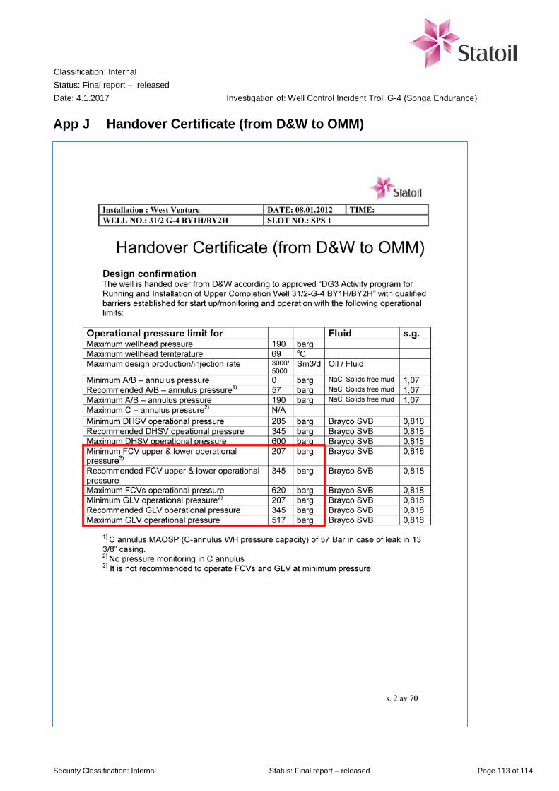
Classification: Internal Status: Final report – released Date: 4.1.2017
Investigation of: Well Control Incident Troll G-4 (Songa Endurance)
Security Classification: Internal Status: Final report – released Page 113 of 114
App J Handover Certificate (from D&W to OMM)
Classification: Internal Status: Final report – released Date: 4.1.2017
Investigation of: Well Control Incident Troll G-4 (Songa Endurance)
Security Classification: Internal Status: Final report – released Page 114 of 114
App K Gas hazard analysis, gas leak on Songa Endurance
On the following pages, the final, signed version of the Gas hazard analysis for the well control incident is enclosed.

Classification: Internal Status: Final Expiry date: 2017-12-31 Page 1 of 25
Gas hazard analysis, gas leak on Songa Endurance 15.10.2016 (Synergi no. 1488377)


Gas hazard analysis, gas leak on Songa Endurance 15.10.2016 (Synergi no. 1488377)
Doc. No. Valid from Rev. no. 2016-12-22
Classification: Internal Status: Final Expiry date: 2017-12-31 Page 4 of 26
1 Introduction
TPD R&T FT SST has assisted COA in conjunction with a well control incident at Songa Endurance drilling rig October 15, 2016. Songa Endurance was working on the G4 well in the Troll field near Troll B when complications arose during the work on removing the production string from the well [1]. During the pulling operation of the tubing hanger in well G-4 (P&A operation), the tubing hanger came free unexpected/prematurely and the string was moved up 5-6 meter and the riser was evacuated for water by gas trapped under the tubing hanger, resulting in a big water spray on the drill floor which covered the entire driller's cabin. When water appeared on the drill floor the annular preventer, and then the shear&seal ram, was closed [5]. Natural gas was released into the derrick through the riser outlet, and HC detectors were activated, resulting in a general muster alarm. A gas hazard analysis has been performed to provide an estimate of the leak flow rate and gas dispersion of the gas leak on the drill floor on Songa Endurance. The commercial code FLACS has been used to describe a picture of the gas dispersion of the incident. FLACS has also been used to assess sensitivities. FLACS v10.5 is developed by GexCon / CMR (Bergen) [2].
2 Prerequisites
The calculations are based on information and documentation received from the investigation team, including process parameters, meteorology data, event log and geometry model. The gas composition in the calculations has been simplified to pure methane gas: The Troll field contains > 94% methane by volume.
3 Estimation of leak size
For verified process conditions and known geometric hole size it is possible to calculate the leak rate using a dispersion calculation tool. Parameters normally included in such calculations are process pressure and temperature, gas composition and hole size. This is this report referred to as method 1. One can also use registered gas detector recordings to form a gas dispersion map (at different times) and use 3D CFD (Computational Fluid Dynamics) simulations to backtrack towards a leak size that matches the observed values. This approach is in this report referred to as method 2.
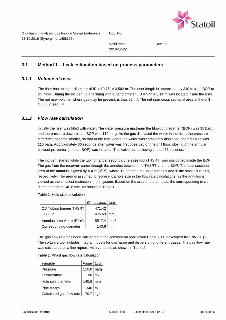
Gas hazard analysis, gas leak on Songa Endurance 15.10.2016 (Synergi no. 1488377)
Doc. No. Valid from Rev. no. 2016-12-22
Classification: Internal Status: Final Expiry date: 2017-12-31 Page 5 of 26
3.1 Method 1 – Leak estimation based on process parameters
3.1.1 Volume of riser
The riser has an inner diameter of ID = 19.75” = 0.502 m. The riser length is approximately 340 m from BOP to drill floor. During the incident, a drill string with outer diameter OD = 5.5” = 0.14 m was located inside the riser. The net riser volume, where gas may be present, is thus 62 m3. The net riser cross sectional area at the drill floor is 0.163 m2.
3.1.2 Flow rate calculation
Initially the riser was filled with water. The water pressure upstream the blowout preventer (BOP) was 35 barg, and the pressure downstream BOP was 110 barg. As the gas displaced the water in the riser, the pressure difference became smaller, so that at the time where the water was completely displaced, the pressure was 110 barg. Approximately 30 seconds after water was first observed on the drill floor, closing of the annular blowout preventer (annular BOP) was initiated. This valve has a closing time of 38 seconds. The incident started while the tubing hanger secondary release tool (THSRT) was positioned inside the BOP. The gas from the reservoir came through the annulus between the THSRT and the BOP. The total sectional area of the annulus is given by A = π*(R2-r2), where ‘R’ denotes the largest radius and ‘r’ the smallest radius, respectively. The area is assumed to represent a hole size in the flow rate calculations, as the annulus is viewed as the smallest restriction in the system. Based on the area of the annulus, the corresponding circle diameter is thus 140.6 mm, as shown in Table 1.
Table 1. Hole size calculation
Dimensions Unit OD Tubing hanger THSRT 471.42 mm ID BOP 476.63 mm
Annulus area A = π*(R2-r2) 15517.4 mm2 Corresponding diameter 140.6 mm
The gas flow rate has been calculated in the commercial application Phast 7.11, developed by DNV GL [3]. The software tool includes integral models for discharge and dispersion of different gases. The gas flow rate was calculated as a line rupture, with variables as shown in Table 2.
Table 2. Phast gas flow rate calculation
Variable Value Unit Pressure 110.0 barg Temperature 50 °C
Hole size diameter 140.6 mm
Pipe length 340 m Calculated gas flow rate 70.7 kg/s
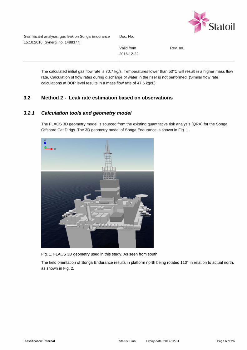
Gas hazard analysis, gas leak on Songa Endurance 15.10.2016 (Synergi no. 1488377)
Doc. No. Valid from Rev. no. 2016-12-22
Classification: Internal Status: Final Expiry date: 2017-12-31 Page 6 of 26
The calculated initial gas flow rate is 70.7 kg/s. Temperatures lower than 50°C will result in a higher mass flow rate. Calculation of flow rates during discharge of water in the riser is not performed. (Similar flow rate calculations at BOP level results in a mass flow rate of 47.6 kg/s.)
3.2 Method 2 - Leak rate estimation based on observations
3.2.1 Calculation tools and geometry model
The FLACS 3D geometry model is sourced from the existing quantitative risk analysis (QRA) for the Songa Offshore Cat D rigs. The 3D geometry model of Songa Endurance is shown in Fig. 1.
Fig. 1. FLACS 3D geometry used in this study. As seen from south
The field orientation of Songa Endurance results in platform north being rotated 110° in relation to actual north, as shown in Fig. 2.

Gas hazard analysis, gas leak on Songa Endurance 15.10.2016 (Synergi no. 1488377)
Doc. No. Valid from Rev. no. 2016-12-22
Classification: Internal Status: Final Expiry date: 2017-12-31 Page 7 of 26
Fig. 2. Songa Endurance field orientation with prevailing wind direction during the incident, based on [4].
3.2.2 Weather conditions
The weather situation during the incident is reported as: − Wind direction from North East (043°) − Wind speed ~ 5 knots (2,5 m/s) − Ambient temperature 10°C
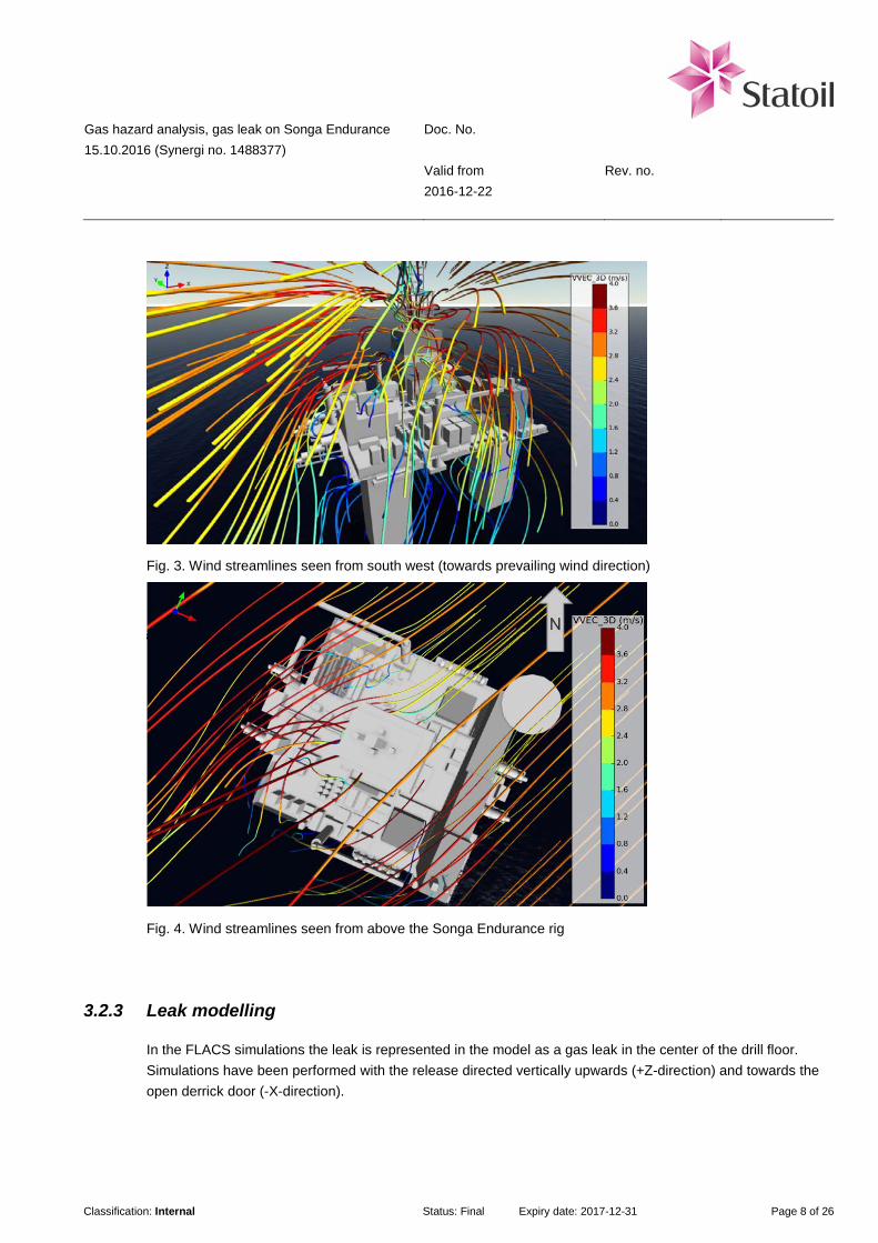
Gas hazard analysis, gas leak on Songa Endurance 15.10.2016 (Synergi no. 1488377)
Doc. No. Valid from Rev. no. 2016-12-22
Classification: Internal Status: Final Expiry date: 2017-12-31 Page 8 of 26
Fig. 3. Wind streamlines seen from south west (towards prevailing wind direction)
Fig. 4. Wind streamlines seen from above the Songa Endurance rig
3.2.3 Leak modelling
In the FLACS simulations the leak is represented in the model as a gas leak in the center of the drill floor. Simulations have been performed with the release directed vertically upwards (+Z-direction) and towards the open derrick door (-X-direction).
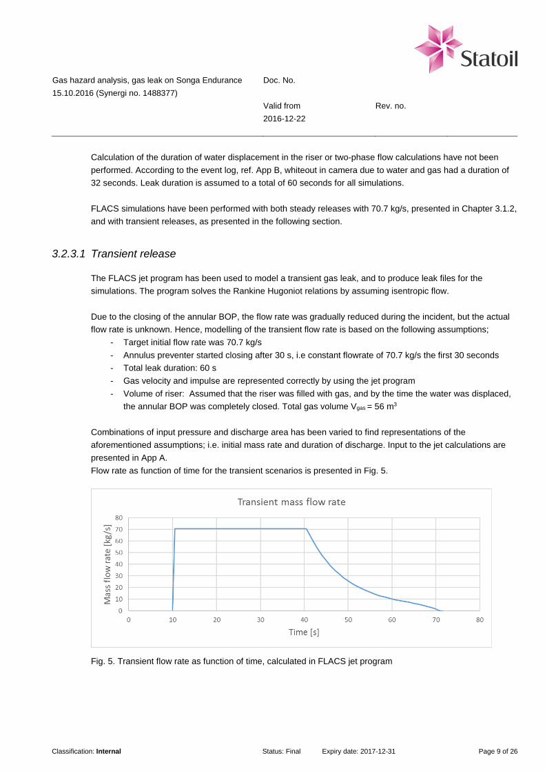
Gas hazard analysis, gas leak on Songa Endurance 15.10.2016 (Synergi no. 1488377)
Doc. No. Valid from Rev. no. 2016-12-22
Classification: Internal Status: Final Expiry date: 2017-12-31 Page 9 of 26
Calculation of the duration of water displacement in the riser or two-phase flow calculations have not been performed. According to the event log, ref. App B, whiteout in camera due to water and gas had a duration of 32 seconds. Leak duration is assumed to a total of 60 seconds for all simulations. FLACS simulations have been performed with both steady releases with 70.7 kg/s, presented in Chapter 3.1.2, and with transient releases, as presented in the following section.
3.2.3.1 Transient release
The FLACS jet program has been used to model a transient gas leak, and to produce leak files for the simulations. The program solves the Rankine Hugoniot relations by assuming isentropic flow. Due to the closing of the annular BOP, the flow rate was gradually reduced during the incident, but the actual flow rate is unknown. Hence, modelling of the transient flow rate is based on the following assumptions;
- Target initial flow rate was 70.7 kg/s - Annulus preventer started closing after 30 s, i.e constant flowrate of 70.7 kg/s the first 30 seconds - Total leak duration: 60 s - Gas velocity and impulse are represented correctly by using the jet program - Volume of riser: Assumed that the riser was filled with gas, and by the time the water was displaced,
the annular BOP was completely closed. Total gas volume Vgas = 56 m3 Combinations of input pressure and discharge area has been varied to find representations of the aforementioned assumptions; i.e. initial mass rate and duration of discharge. Input to the jet calculations are presented in App A. Flow rate as function of time for the transient scenarios is presented in Fig. 5.
Fig. 5. Transient flow rate as function of time, calculated in FLACS jet program
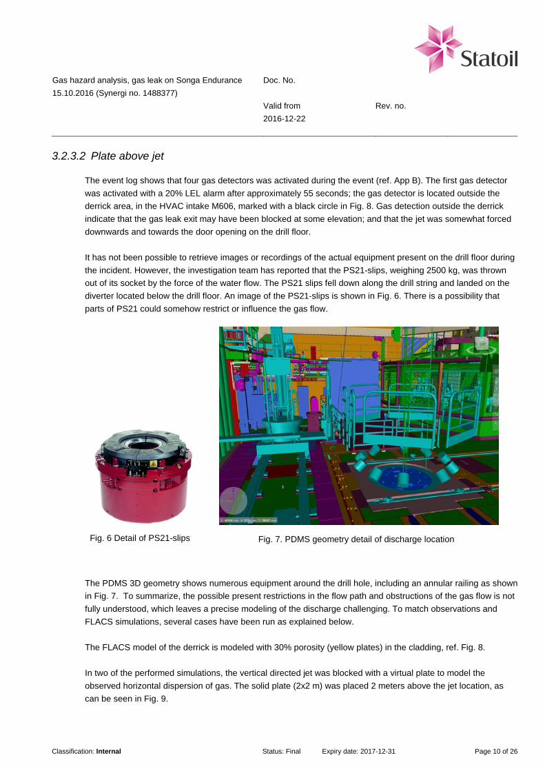
Gas hazard analysis, gas leak on Songa Endurance 15.10.2016 (Synergi no. 1488377)
Doc. No. Valid from Rev. no. 2016-12-22
Classification: Internal Status: Final Expiry date: 2017-12-31 Page 10 of 26
3.2.3.2 Plate above jet
The event log shows that four gas detectors was activated during the event (ref. App B). The first gas detector was activated with a 20% LEL alarm after approximately 55 seconds; the gas detector is located outside the derrick area, in the HVAC intake M606, marked with a black circle in Fig. 8. Gas detection outside the derrick indicate that the gas leak exit may have been blocked at some elevation; and that the jet was somewhat forced downwards and towards the door opening on the drill floor. It has not been possible to retrieve images or recordings of the actual equipment present on the drill floor during the incident. However, the investigation team has reported that the PS21-slips, weighing 2500 kg, was thrown out of its socket by the force of the water flow. The PS21 slips fell down along the drill string and landed on the diverter located below the drill floor. An image of the PS21-slips is shown in Fig. 6. There is a possibility that parts of PS21 could somehow restrict or influence the gas flow.
Fig. 6 Detail of PS21-slips
Fig. 7. PDMS geometry detail of discharge location
The PDMS 3D geometry shows numerous equipment around the drill hole, including an annular railing as shown in Fig. 7. To summarize, the possible present restrictions in the flow path and obstructions of the gas flow is not fully understood, which leaves a precise modeling of the discharge challenging. To match observations and FLACS simulations, several cases have been run as explained below. The FLACS model of the derrick is modeled with 30% porosity (yellow plates) in the cladding, ref. Fig. 8. In two of the performed simulations, the vertical directed jet was blocked with a virtual plate to model the observed horizontal dispersion of gas. The solid plate (2x2 m) was placed 2 meters above the jet location, as can be seen in Fig. 9.
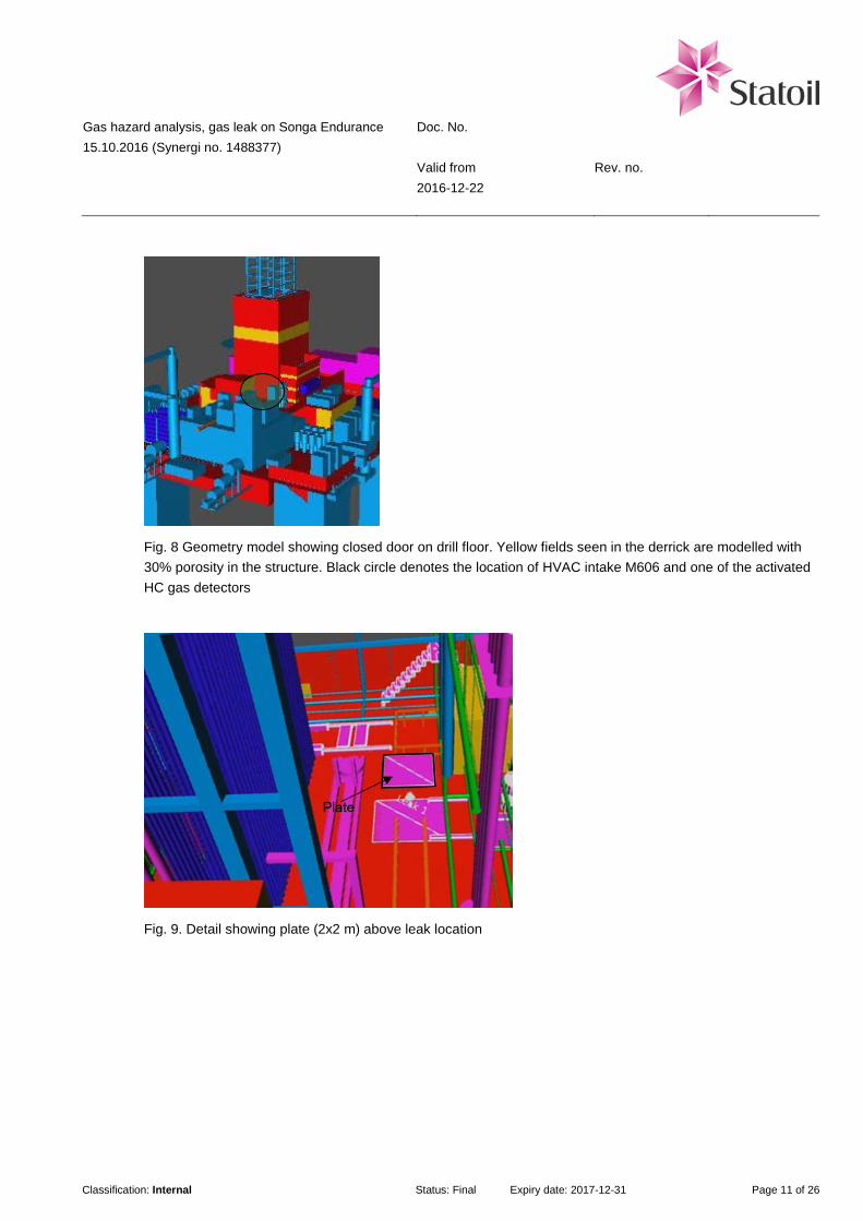
Gas hazard analysis, gas leak on Songa Endurance 15.10.2016 (Synergi no. 1488377)
Doc. No. Valid from Rev. no. 2016-12-22
Classification: Internal Status: Final Expiry date: 2017-12-31 Page 11 of 26
Fig. 8 Geometry model showing closed door on drill floor. Yellow fields seen in the derrick are modelled with 30% porosity in the structure. Black circle denotes the location of HVAC intake M606 and one of the activated HC gas detectors
Fig. 9. Detail showing plate (2x2 m) above leak location

Gas hazard analysis, gas leak on Songa Endurance 15.10.2016 (Synergi no. 1488377)
Doc. No. Valid from Rev. no. 2016-12-22
Classification: Internal Status: Final Expiry date: 2017-12-31 Page 12 of 26
Fig. 10. Detail showing the porous plate (2x3 m) above the leak location and the solid plate (1x3 m) in the -X direction (towards the open door). The railing (brown) was moved to correspond with the PDMS model.
3.2.4 Gas dispersion simulation results
A total of 10 FLACS simulations are reported here. The simulation grid was built according to FLACS guidelines, and based on 1 m cubic grid cells with a 20% stretching from the outside of the platform legs. In general, each simulation consisted of a total of ~500k grid cells. The FLACS gas dispersion calculations were modeled with a gas velocity of 250 m/s. The transient scenarios had an initial gas velocity of 240 m/s. Relevant scenarios are listed in Table 3. Results from the gas dispersion analysis are shown in Fig. 11 - Fig. 21.
Table 3. FLACS scenarios
Case Scenario Rate [kg/s]
Wind velocity [m/s]
Wind direction
Leak direction
Monitor points
Transient Leak obstacle
Open door
1 010104 46,7 2,57 North east +Z X* - - - 2 010102 70,7 2,57 North east +Z X* - - - 3 010203 70,7 2,57 North east +Z X* X X 4 010204 70,7 2,57 North east -X X* X X X 5 010300 46,7 2,57 North east +Z X* - X - 6 010500 70,7 2,57 North east +Z X* - X X 7 010502 70,7 2,57 North east -Z X - X X 8 010512 70,7 2,57 North east -X X - X X 9 010600 70,7 2,57 North east +Z X - X** X
10 010602 70,7 2,57 North east +Z X - X*** X * ref. table 4
** ref. fig.10
*** porous plate 50% on top, ref. fig.9
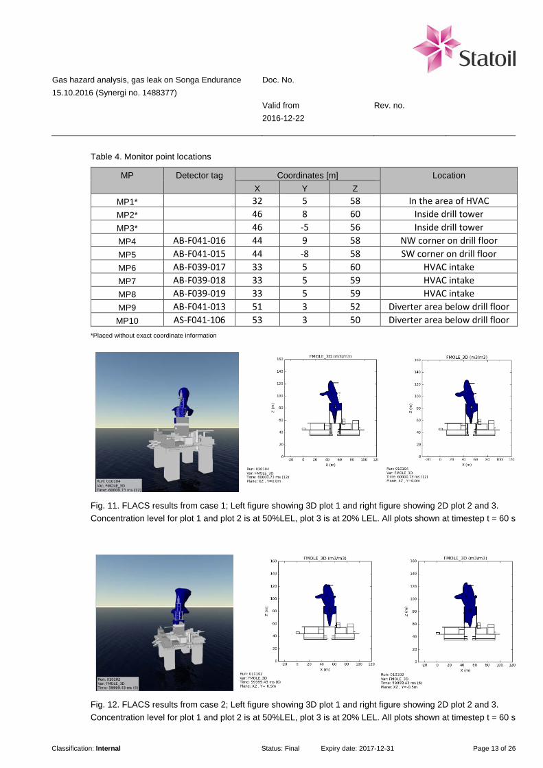
Gas hazard analysis, gas leak on Songa Endurance 15.10.2016 (Synergi no. 1488377)
Doc. No. Valid from Rev. no. 2016-12-22
Classification: Internal Status: Final Expiry date: 2017-12-31 Page 13 of 26
Table 4. Monitor point locations
MP Detector tag Coordinates [m] Location X Y Z
MP1* 32 5 58 In the area of HVAC MP2* 46 8 60 Inside drill tower MP3* 46 -5 56 Inside drill tower MP4 AB-F041-016 44 9 58 NW corner on drill floor MP5 AB-F041-015 44 -8 58 SW corner on drill floor MP6 AB-F039-017 33 5 60 HVAC intake MP7 AB-F039-018 33 5 59 HVAC intake MP8 AB-F039-019 33 5 59 HVAC intake MP9 AB-F041-013 51 3 52 Diverter area below drill floor
MP10 AS-F041-106 53 3 50 Diverter area below drill floor *Placed without exact coordinate information
Fig. 11. FLACS results from case 1; Left figure showing 3D plot 1 and right figure showing 2D plot 2 and 3. Concentration level for plot 1 and plot 2 is at 50%LEL, plot 3 is at 20% LEL. All plots shown at timestep t = 60 s
Fig. 12. FLACS results from case 2; Left figure showing 3D plot 1 and right figure showing 2D plot 2 and 3. Concentration level for plot 1 and plot 2 is at 50%LEL, plot 3 is at 20% LEL. All plots shown at timestep t = 60 s
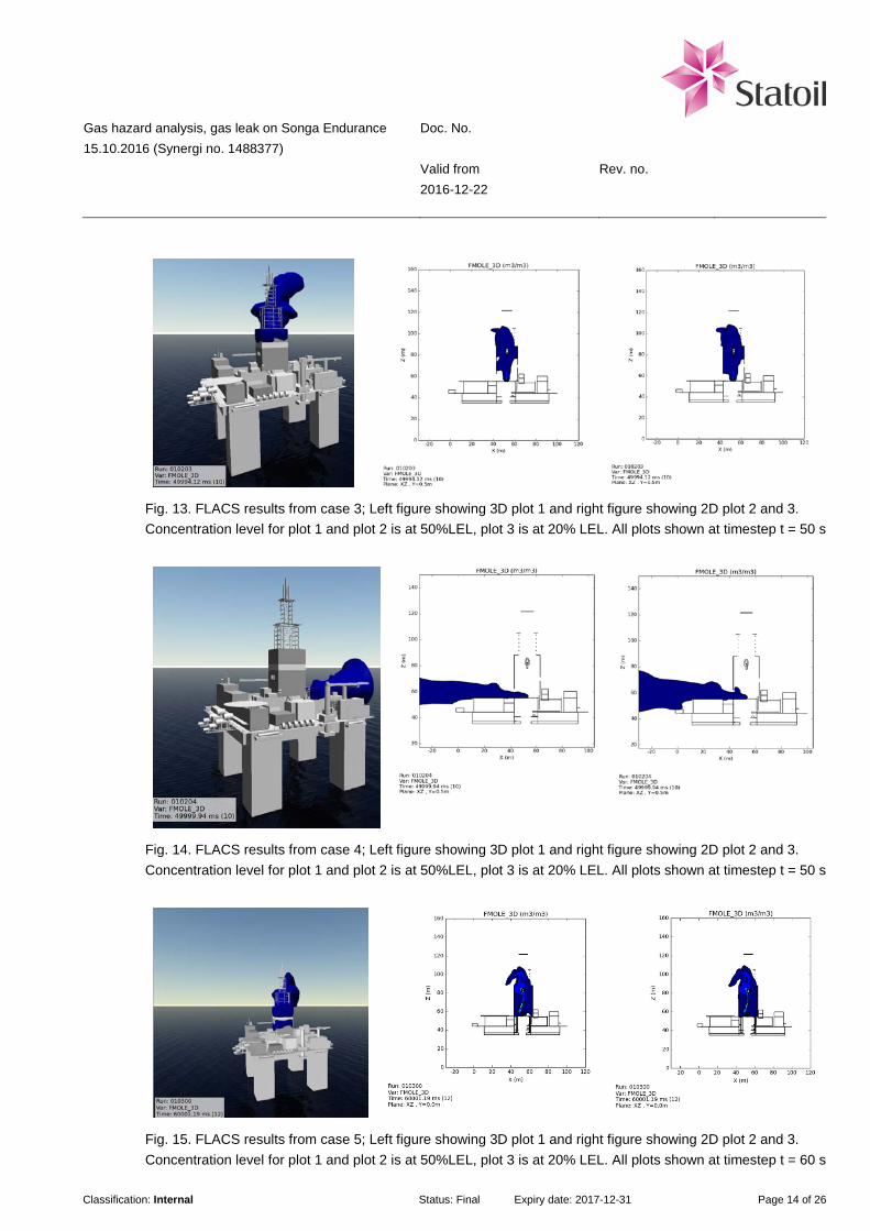
Gas hazard analysis, gas leak on Songa Endurance 15.10.2016 (Synergi no. 1488377)
Doc. No. Valid from Rev. no. 2016-12-22
Classification: Internal Status: Final Expiry date: 2017-12-31 Page 14 of 26
Fig. 13. FLACS results from case 3; Left figure showing 3D plot 1 and right figure showing 2D plot 2 and 3. Concentration level for plot 1 and plot 2 is at 50%LEL, plot 3 is at 20% LEL. All plots shown at timestep t = 50 s
Fig. 14. FLACS results from case 4; Left figure showing 3D plot 1 and right figure showing 2D plot 2 and 3. Concentration level for plot 1 and plot 2 is at 50%LEL, plot 3 is at 20% LEL. All plots shown at timestep t = 50 s
Fig. 15. FLACS results from case 5; Left figure showing 3D plot 1 and right figure showing 2D plot 2 and 3. Concentration level for plot 1 and plot 2 is at 50%LEL, plot 3 is at 20% LEL. All plots shown at timestep t = 60 s
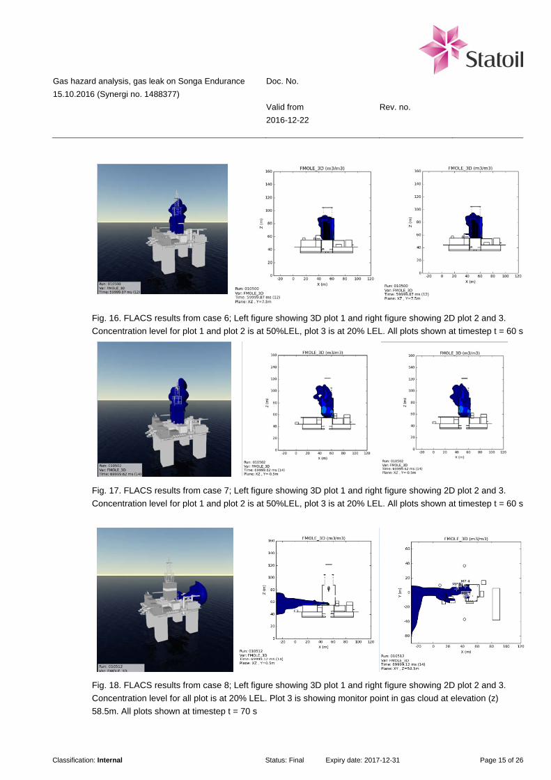
Gas hazard analysis, gas leak on Songa Endurance 15.10.2016 (Synergi no. 1488377)
Doc. No. Valid from Rev. no. 2016-12-22
Classification: Internal Status: Final Expiry date: 2017-12-31 Page 15 of 26
Fig. 16. FLACS results from case 6; Left figure showing 3D plot 1 and right figure showing 2D plot 2 and 3. Concentration level for plot 1 and plot 2 is at 50%LEL, plot 3 is at 20% LEL. All plots shown at timestep t = 60 s
Fig. 17. FLACS results from case 7; Left figure showing 3D plot 1 and right figure showing 2D plot 2 and 3. Concentration level for plot 1 and plot 2 is at 50%LEL, plot 3 is at 20% LEL. All plots shown at timestep t = 60 s
Fig. 18. FLACS results from case 8; Left figure showing 3D plot 1 and right figure showing 2D plot 2 and 3. Concentration level for all plot is at 20% LEL. Plot 3 is showing monitor point in gas cloud at elevation (z) 58.5m. All plots shown at timestep t = 70 s

Gas hazard analysis, gas leak on Songa Endurance 15.10.2016 (Synergi no. 1488377)
Doc. No. Valid from Rev. no. 2016-12-22
Classification: Internal Status: Final Expiry date: 2017-12-31 Page 16 of 26
Fig. 19. FLACS results from case 9; Left figure showing 3D plot 1 and right figure showing 2D plot 2 and 3. Concentration level for plot 1 and plot 2 is at 50%LEL, plot 3 is at 20% LEL. All plots shown at timestep t = 70 s
Fig. 20. FLACS results from case 10; Left figure showing 3D plot 1 and right figure showing 2D plot 2 and 3. Concentration level for plot 1 and plot 2 is at 50%LEL, plot 3 is at 20% LEL. All plots shown at timestep t = 70 s
Table 5 shows scenarios where gas concentration levels are at- and above 20%LEL, detected at the location of various gas detectors. Table 5. Monitors that detected concentration levels at and above 20%LFL
Case Scenario FMOLE [m³/m³] MP4 MP5 MP6 MP7 MP8 MP9 MP10
3 010203 4 010204 x x x x x 7 010502 x x x 8 010512 x x x x x 9 010600 x x 10 010602

Gas hazard analysis, gas leak on Songa Endurance 15.10.2016 (Synergi no. 1488377)
Doc. No. Valid from Rev. no. 2016-12-22
Classification: Internal Status: Final Expiry date: 2017-12-31 Page 17 of 26
Concentration levels in monitor points as function of time are presented in Fig. 21.
Case 7
Case 8
Case 9
Case 10
Fig. 21. FLACS results showing volume mole fraction (FMOLE) as function of time in the event for four different scenarios
3.2.5 Discussion of the FLACS simulations
Case 1 and 2 was simulated to see the range and shape of the gas dispersion. As can be seen from Fig. 11 and Fig. 12, the gas dispersion is directed vertically upwards above the weather cladding and the dispersion is governed by the wind. Case 3 was simulated to investigate the transient mass flow rate from the start of the gas leakage up to a duration of 60 seconds, ref. Fig. 13. The leak direction was vertically upwards. The results show a dispersion with the same development as case 1 and case 2 initially, but as the flow rate starts to drop, the gas cloud size is reduced accordingly. The second transient release (case 4) was simulated with the jet directed towards the door opening in the derrick, as shown in Fig. 14. Results show that monitors located in the HVAC intake were activated (~8%vol). Case 5 to case 10 were simulated with various leak directions, according to Table 3, and with various obstructions around the leak location as explained in chapter 3.2.3.2 Plate above jet.

Gas hazard analysis, gas leak on Songa Endurance 15.10.2016 (Synergi no. 1488377)
Doc. No. Valid from Rev. no. 2016-12-22
Classification: Internal Status: Final Expiry date: 2017-12-31 Page 18 of 26
To summarize, the current FLACS simulations show two quite different results: A) either directed vertically upwards (flammable gas cloud inside derrick) or, B) directed out of the open door (jet direction). Simulated cases with 20%LEL gas concentration detected by monitors are listed in Table 5. Results from monitors are shown in Fig. 21. In this study it has not been possible to model a gas dispersion scenario in FLACS that fit with the recorded activated gas detectors (i.e. at drill floor level and with correct sequence as listed in event log, App B). The possible restrictions present in the flow path and obstructions of the gas flow is not fully understood, which leaves precise modeling of the discharge challenging. In addition, the water forced out of the riser may have acted as a kind of deluge when falling down on the drill floor. This may have forced parts of the gas cloud downwards and possibly outwards, and could explain the recorded HC gas detections, both in the HVAC air intake and the two detectors located at the drill floor level. The FLACS results from method 2 do not fit with the recorded activated gas detectors, ref. App B. According to the event log, the first activated gas detector located on the drill floor was F041-016 (denoted MP4 in FLACS simulations). The second activated gas detector located on drill floor was F041-015 (denoted MP5 in FLACS simulations). In comparison the FLACS simulations reported here had an opposite course of events, where MP5 was activated prior to MP4. Furthermore, the HVAC air intake in the FLACS 3D model was inaccurate, which may explain why the FLACS results show a lower level of gas than the actual observations. Uncertainties are listed in chapter 5.
4 Sensitivities
4.1 Ignition
There has not been performed separate explosion calculations or assessments of ignition sources in this study. This is because the dispersion simulations do not give the expected results in terms of detected gas in the area. An assessment of consequences of a potential ignition during the incident is based on the valid Songa Endurance QRA [6]. According to the QRA, the frequency for ignited well releases and blowouts in the relevant area is 1.12E-04 per year and 5.41E-05 per year, respectively [6]. An immediate ignition, would cause a jet fire scenario. With a delayed ignition, a gas cloud would have had time to develop; and could consequently cause an explosion.

Gas hazard analysis, gas leak on Songa Endurance 15.10.2016 (Synergi no. 1488377)
Doc. No. Valid from Rev. no. 2016-12-22
Classification: Internal Status: Final Expiry date: 2017-12-31 Page 19 of 26
Explosion assessments are treated in Appendix H in the QRA. Explosion pressure results are provided for stoichiometric gas cloud sizes with 10%, 20% and 30% degree of filling of the total derrick volume. The results are assumed to be representative for this study. From chapter 10.1.3, QRA main report [6]: “Regarding explosion loads, the explosion assessment in the QRA considers 0.1 barg overpressure to be an appropriate design load for the drill floor and that a 0.05 barg drag load is appropriate design load for safety critical equipment. According to equipment supplier Aker Solutions, it is considered that safety critical equipment on drill floor is able to withstand such explosion loads (Ref. 22).” The quoted QRA refers to explosion pressures in the region of 10% and 20% stoichiometric gas cloud sizes, based on the most likely event occurring. Considering the explosion pressure from the 30 % stoichiometric gas cloud sizes, the explosion pressure can generate pressures as high as 0.5 barg (ref. Figure 3.7, Appendix H [6]). With the calculated leak size for this incident, it is possible that a 30% stoichiometric gas cloud size were formed during the event. Therefore, the consequences of a gas cloud explosion in the drill tower would have potential for fatalities. If the gas cloud was immediately ignited, a fire would have occurred. The QRA presents results for a 35 kg/s and a 150 kg/s blowout/well release. From Chapter 2.2.2 (Restricted blowout/well release (representative rate 35 kg/s)), Attachment G2 [6]: “A2 – Drill floor & above: For vertical jet fires, at low wind speeds below 4 m/s, fire flame and smoke could potentially rise and engulf the drill floor, hence impair the escape routes for A2 – Drill floor & above. […] “A4 – Main deck/open deck: Considering the Main deck/open deck area is big around the derrick, it is expected that the escape routes from the area will be impaired when the wind is blowing from any direction below 2 m/s. The escape routes at only at the downstream could potentially be impaired when the wind speed is above 2 m/s. For horizontal jets, the escape routes at the jet downstream could potentially be lost.” Considering this incident, a 70 kg/s blowout, it is believed that in an immediately ignited scenario; fire flame and smoke could potentially rise and engulf the drill floor, hence impair the escape routes for A2 – Drill floor & above. For the main deck/open deck: The escape routes downwind could potentially be impaired, given that the wind speed was above 2 m/s during the incident. For horizontal jets, the escape routes at the jet downstream could potentially be lost. Therefore, the consequences of a 70 kg/s blowout fire on the drill floor would have the potential of fatalities.

Gas hazard analysis, gas leak on Songa Endurance 15.10.2016 (Synergi no. 1488377)
Doc. No. Valid from Rev. no. 2016-12-22
Classification: Internal Status: Final Expiry date: 2017-12-31 Page 20 of 26
5 Uncertainties
Leak size: The leak rate is calculated based on the area of the annulus between the BOP and the THSRT. This area is then assumed circular, to obtain a hole size diameter. This assumption is necessary to calculate a mass flow rate based on process parameters. Gas composition: As agreed with the investigation team, the composition is assumed pure methane gas. With a methane content of 94% by volume, the contribution of heavier components is considered to have a negligble effect of the buoyancy of the gas plume. Leak location: The leak location is assumed to be at drill floor, in the rotary. The uncertainties of method 2 in study are divided in to 2 groups, the model inputs and the scenarios. 1) Model inputs:
• Geometrical model o The FLACS model was used in the latest TRA, received from Songa
• Grid -numeric resolution o 1 grid resolution with 1 meter cells was used.
• Boundary conditions o The wind speeds used in simulations is representative for the field at the time of
the event. o Wind direction used in the simulations is representative for the field at the time of
the event. o Temperature – the temperature of 10 °C is representative for the field at the time
of the event. o Turbulence – in FLACS scenario two inputs is set for the turbulence. The relative
turbulence intensity and the turbulence length scale. These inputs are for the leak and wind condition; both are according to recommendations in the FLACS manual.
2) Scenarios: Uncertainties can be in the input parameters. Ref. chapter 2. input received from COA.
5.1 Discussion on the uncertainties
The overall geometry model used in the simulations is evaluated to be representative for this study. There is an uncertainty of the arrangement of equipment being displaced during the event, and partially around the leak area. This uncertainty will subsequently lead to an uncertainty in the leak direction, and any obstructions possibly influencing the leakage outlet (obstructing the leak area or divert the gas flow in any way). Atmospheric turbulence parameters are adopted according to best practice and user guidelines. Grid sensitivity simulations have not been performed.

Gas hazard analysis, gas leak on Songa Endurance 15.10.2016 (Synergi no. 1488377)
Doc. No. Valid from Rev. no. 2016-12-22
Classification: Internal Status: Final Expiry date: 2017-12-31 Page 21 of 26
6 Conclusion
It is believed that in general, most of the gas was dispersed vertically upwards. The spray of water was observed above the weather cladding of the derrick, and it is reasonable to assume that the gas was initially forced in the same direction. However, the water forced out of the riser may have acted as a kind of deluge when falling down on the drill floor. This may have forced parts of the gas cloud downwards and possibly outwards, and could explain the activated HC gas detector recordings, both in the HVAC air intake and the two detectors located at the drill floor level. The current CFD tool is not suited for calculating the impact of water on gas cloud dispersions. Due to a low number of recordings (four gas detectors that were activated) during this event, it has been impossible to generate a credible dispersion sketch for comparison with the FLACS results. The monitor results show that simulation case 4, case 7 and case 8 give 20% LFL gas concentrations in the simulated gas detector locations. It has not been possible to reproduce a dispersion simulation that corresponds to the event log result sequence of the monitors, ref. App B. Considering the uncertainties discussed in chapter 5 and the results in chapter 3.2.5 from the FLACS simulations, method 2 can only be used to indicate what may have happened, and can not be applied quantitatively. From the recordings it seems as if the gas to a certain degree was accumulated at the level of the detectors, while the simulations indicate that gas was not accumulated at lower levels but was rising upwards. The FLACS results from method 2 do not fit with the recorded activated gas detectors, ref. App B. According to the event log, the first activated gas detector located on the drill floor was F041-016 (denoted MP4 in FLACS simulations). The second activated gas detector located on drill floor was F041-015 (denoted MP5 in FLACS simulations). In comparison the FLACS simulations reported here had an opposite course of events, where MP5 was activated prior to MP4. Furthermore, the HVAC air intake in the FLACS 3D model was inaccurate, which may explain why the FLACS results show a lower level of gas than the actual observations.

Gas hazard analysis, gas leak on Songa Endurance 15.10.2016 (Synergi no. 1488377)
Doc. No. Valid from Rev. no. 2016-12-22
Classification: Internal Status: Final Expiry date: 2017-12-31 Page 22 of 26
7 References
[1]. Statoil.com: Well incident at Songa Endurance, accessed 28.11.2016; http://www.statoil.com/en/NewsAndMedia/News/2016/Pages/15Oct_SE.aspx
[2]. FLACS v.10.5, GexCon/CMR, Flame Acceleration Simulator; www.gexcon.com/flacs-software [3]. Phast 7.11, DNV GL, Process Hazard Analysis Software Tool;
https://www.dnvgl.com/services/process-hazard-analysis-phast-1675 [4]. Statoil report; TPD D&W MU Troll, Songa Endurance Troll production drilling: «Location specific risk
and emergency preparedness review» Well No 31/2-G-4, dated 15.09.2016 [5]. Statoil Synergi, no. 1488377; http://synergi.statoil.no/synergix/default.aspx, accessed 02.12.2016 [6]. QRA, Quantitative Risk Analysis for Songa Endurance, END-013-06-001 rev. 3.0, issue date: 12
august 2016.
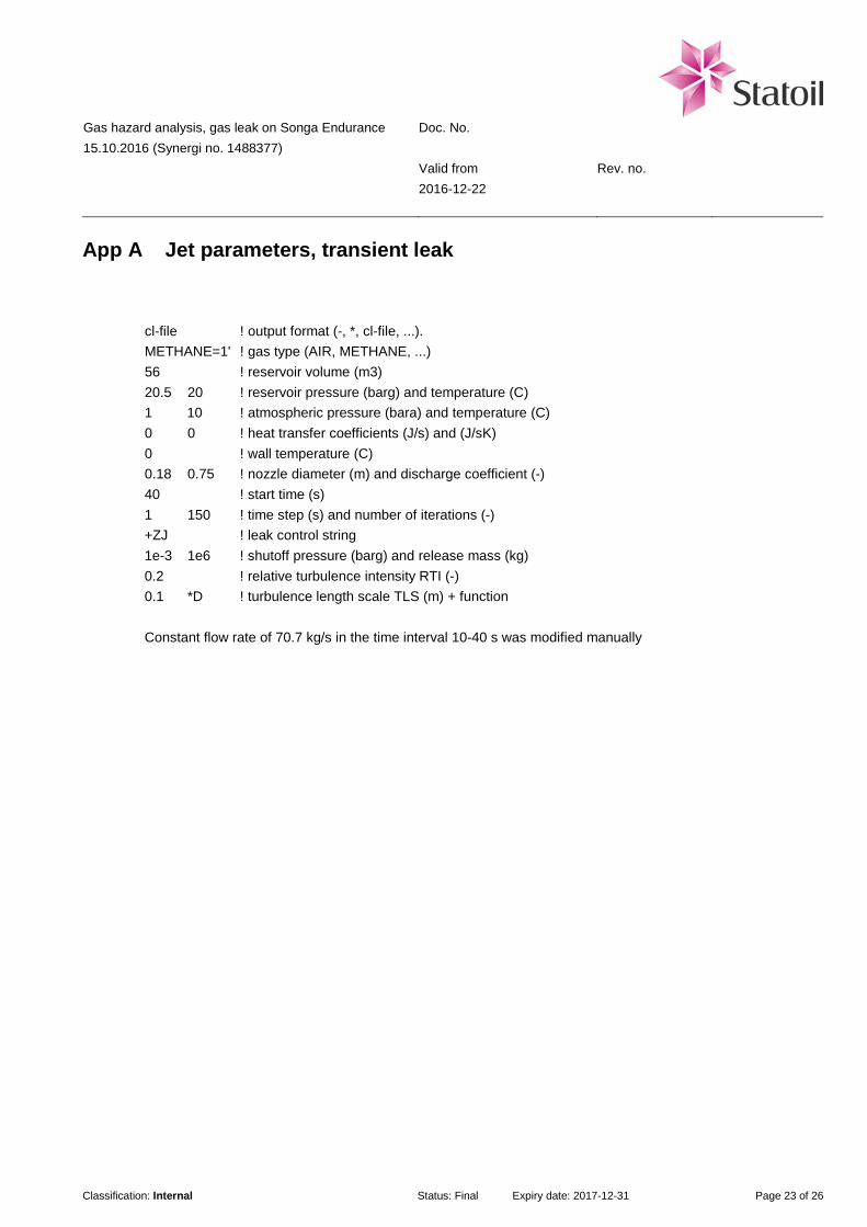
Gas hazard analysis, gas leak on Songa Endurance 15.10.2016 (Synergi no. 1488377)
Doc. No. Valid from Rev. no. 2016-12-22
Classification: Internal Status: Final Expiry date: 2017-12-31 Page 23 of 26
App A Jet parameters, transient leak
cl-file ! output format (-, *, cl-file, ...). METHANE=1' ! gas type (AIR, METHANE, ...) 56 ! reservoir volume (m3) 20.5 20 ! reservoir pressure (barg) and temperature (C) 1 10 ! atmospheric pressure (bara) and temperature (C) 0 0 ! heat transfer coefficients (J/s) and (J/sK) 0 ! wall temperature (C) 0.18 0.75 ! nozzle diameter (m) and discharge coefficient (-) 40 ! start time (s) 1 150 ! time step (s) and number of iterations (-) +ZJ ! leak control string 1e-3 1e6 ! shutoff pressure (barg) and release mass (kg) 0.2 ! relative turbulence intensity RTI (-) 0.1 *D ! turbulence length scale TLS (m) + function Constant flow rate of 70.7 kg/s in the time interval 10-40 s was modified manually
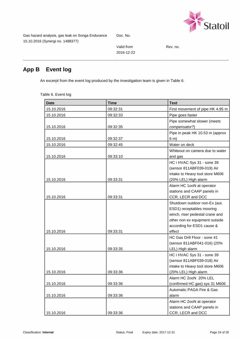
Gas hazard analysis, gas leak on Songa Endurance 15.10.2016 (Synergi no. 1488377)
Doc. No. Valid from Rev. no. 2016-12-22
Classification: Internal Status: Final Expiry date: 2017-12-31 Page 24 of 26
App B Event log
An excerpt from the event log produced by the investigation team is given in Table 6.
Table 6. Event log
Date Time Text 15.10.2016 09:32:31 First movement of pipe HK 4.95 m 15.10.2016 09:32:33 Pipe goes faster
15.10.2016 09:32:35 Pipe somewhat slower (meets compensator?)
15.10.2016 09:32:37 Pipe in peak HK 10.53 m (approx 6 m)
15.10.2016 09:32:45 Water on deck
15.10.2016 09:33:10 Whiteout on camera due to water and gas
15.10.2016 09:33:31
HC i HVAC Sys 31 - sone 39 (sensor 811ABF039-019) Air intake to Heavy tool store M606 (20% LEL) High alarm
15.10.2016 09:33:31
Alarm HC 1ooN at operator stations and CAAP panels in CCR, LECR and DCC
15.10.2016 09:33:31
Shutdown outdoor non-Ex (aut. ESD1) receptables mooring winch, riser pedestal crane and other non ex equipment outside according for ESD1 cause & effect
15.10.2016 09:33:35
HC Gas Drill Floor - sone 41 (sensor 811ABF041-016) (20% LEL) High alarm
15.10.2016 09:33:36
HC i HVAC Sys 31 - sone 39 (sensor 811ABF039-018) Air intake to Heavy tool store M606 (20% LEL) High alarm
15.10.2016 09:33:36 Alarm HC 2ooN 20% LEL (confirmed HC gas) sys 31 M606
15.10.2016 09:33:36 Automatic PAGA Fire & Gas alarm
15.10.2016 09:33:36
Alarm HC 2ooN at operator stations and CAAP panels in CCR, LECR and DCC

Gas hazard analysis, gas leak on Songa Endurance 15.10.2016 (Synergi no. 1488377)
Doc. No. Valid from Rev. no. 2016-12-22
Classification: Internal Status: Final Expiry date: 2017-12-31 Page 25 of 26
15.10.2016 09:33:36
HVAC SYS31 Exh Damper Shutdown / Supply Damper Shutdown / Exh Fan Shutdown
15.10.2016 09:33:36 Helideck Gas Warning light activated
15.10.2016 09:33:41
HC Gas Drill Floor - sone 41 (sensor 811ABF041-016) (60% LEL) High-High alarm
15.10.2016 09:33:42 Visibility restored on camera 15.10.2016 09:33:43 Sees hydraulic leak at rotary
15.10.2016 09:33:50
HC Gas Drill Floor - sone 41 (sensor 811ABF041-015) (20% LEL) High alarm
15.10.2016 09:33:50
Alarm HC 2ooN 20% LEL (confirmed HC gas) Sone 41 Drill floor
15.10.2016 09:34:29
HC Gas Drill Floor - sone 41 (sensor 811ABF041-015) (60% LEL) High-High alarm

Gas hazard analysis, gas leak on Songa Endurance 15.10.2016 (Synergi no. 1488377)
Doc. No. Valid from Rev. no. 2016-12-22
Classification: Internal Status: Final Expiry date: 2017-12-31 Page 26 of 26
Table 7. Gas detector event log (extracts from event log)
Time [s] Text TAG Limit 0 First movement of pipe
60 HC in HVAC Air intake F039-019 20%LEL
64 HC in derrick F041-016 20%LEL
65 HC in HVAC Air intake F039-018 20%LEL
70 HC in derrick F041-016 60%LEL
79 HC in derrick F041-015 20%LEL
118 HC in derrick F041-015 60%LEL