Classic 1785 PLC 5 Programmable Controllers User Manual
186
User Manual Classic 1785 PLCĆ5 Programmable Controllers (1785ĆLT, ĆL T2, ĆLT3, ĆL T4) AllenĆBradley
Transcript of Classic 1785 PLC 5 Programmable Controllers User Manual

User
Manual
Classic 1785 PLC�5ProgrammableControllers
(1785�LT, �LT2, �LT3, �LT4)
Allen�Bradley

Because of the variety of uses for the products described in thispublication, those responsible for the application and use of this controlequipment must satisfy themselves that all necessary steps have beentaken to assure that each application and use meets all performance andsafety requirements, including any applicable laws, regulations, codes,and standards.
The illustrations, charts, sample programs, and layout examples shown inthis guide are intended solely for purposes of example. Since there aremany variables and requirements associated with any particularinstallation, Allen-Bradley does not assume responsibility or liability (to include intellectual property liability) for actual use based on theexamples shown in this publication.
Allen-Bradley publication SGI-1.1, Safety Guidelines for the Application,Installation, and Maintenance of Solid State Control (available from yourlocal Allen-Bradley office), describes some important differences betweensolid-state equipment and electromechanical devices that should be takeninto consideration when applying products such as those described inthis publication.
Reproduction of the contents of this copyrighted publication, in wholeor in part, without written permission of Allen-Bradley Company, Inc.,is prohibited.
Throughout this manual we use notes to make you aware ofsafety considerations:
ATTENTION: Identifies information about practices orcircumstances that can lead to personal injury or death,property damage, or economic loss.
Attention statements help you to:
identify a hazard avoid the hazard recognize the consequences
Important: Identifies information that is critical for successful applicationand understanding of the product.
Important User Information

Summary of Changes
i
Summary of Changes
This manual has been revised to cover only Classic PLC-5 programmablecontrollers: PLC-5/10, -5/12, -5/15, and -5/25.
It has also been revised to include the accompanying design worksheetsthat were formerly available as a separate publication: 1785-5.2. Thisseparate publication is no longer available; see Appendix B for theseworksheets.
For information about Enhanced and Ethernet PLC-5 processors, see theEnhanced and Ethernet PLC-5 Programmable Controllers User Manual,publication 1785-6.5.12.

Summary of Changes i. . . . . . . . . . . . . . . . . . . . . . . . . . . .
Classic PLC�5 Programmable Controllers iii. . . . . . . . . . . . .
Purpose of this Manual iii. . . . . . . . . . . . . . . . . . . . . . . . . . . . . . . .
Manual Organization iv. . . . . . . . . . . . . . . . . . . . . . . . . . . . . . . . .
How to Use this Manual iv. . . . . . . . . . . . . . . . . . . . . . . . . . . . . . .
Understanding Your System 1�1. . . . . . . . . . . . . . . . . . . . . . .
Using this Chapter 1�1. . . . . . . . . . . . . . . . . . . . . . . . . . . . . . . . . . .
Understanding the Terms Used in this Chapter 1�1. . . . . . . . . . . . . . .
Designing Systems 1�2. . . . . . . . . . . . . . . . . . . . . . . . . . . . . . . . . .
Preparing Your Functional Specification 1�3. . . . . . . . . . . . . . . . . . . .
Introducing Classic PLC�5 Processor Modules 1�5. . . . . . . . . . . . . . .
Using the Classic PLC�5 Processor as a Remote I/O Scanner 1�8. . . .
Using the Classic PLC�5 Processor as a Remote I/O Adapter 1�9. . . .
Choosing Hardware 2�1. . . . . . . . . . . . . . . . . . . . . . . . . . . . . .
Chapter Objectives 2�1. . . . . . . . . . . . . . . . . . . . . . . . . . . . . . . . . . .
Selecting I/O Modules 2�1. . . . . . . . . . . . . . . . . . . . . . . . . . . . . . . . .
Selecting I/O Adapter Modules 2�4. . . . . . . . . . . . . . . . . . . . . . . . . .
Selecting I/O Chassis 2�6. . . . . . . . . . . . . . . . . . . . . . . . . . . . . . . . .
Selecting an Operator Interface 2�6. . . . . . . . . . . . . . . . . . . . . . . . . .
Choosing a Classic PLC�5 Processor for Your Application 2�9. . . . . . .
Selecting Power Supplies 2�9. . . . . . . . . . . . . . . . . . . . . . . . . . . . . .
Selecting Memory Modules 2�13. . . . . . . . . . . . . . . . . . . . . . . . . . . . .
Selecting a Replacement Battery 2�13. . . . . . . . . . . . . . . . . . . . . . . . .
Selecting Complementary I/O 2�13. . . . . . . . . . . . . . . . . . . . . . . . . . .
Selecting a PLC�5 Processor Backup System 2�14. . . . . . . . . . . . . . .
Selecting Link Terminators 2�15. . . . . . . . . . . . . . . . . . . . . . . . . . . . .
Connecting a Programming Terminal to a Processor Module 2�15. . . . .
Choosing Cables 2�15. . . . . . . . . . . . . . . . . . . . . . . . . . . . . . . . . . . .
Placing System Hardware 3�1. . . . . . . . . . . . . . . . . . . . . . . . .
Chapter Objectives 3�1. . . . . . . . . . . . . . . . . . . . . . . . . . . . . . . . . . .
Determining the Proper Environment 3�1. . . . . . . . . . . . . . . . . . . . . .
Protecting Your Processor 3�4. . . . . . . . . . . . . . . . . . . . . . . . . . . . .
Avoiding Electrostatic Damage 3�4. . . . . . . . . . . . . . . . . . . . . . . . . .
Laying Out Your Cable Raceway 3�4. . . . . . . . . . . . . . . . . . . . . . . . .
Planning Cabling 3�5. . . . . . . . . . . . . . . . . . . . . . . . . . . . . . . . . . . .
Laying Out the Backpanel Spacing 3�6. . . . . . . . . . . . . . . . . . . . . . .
Grounding Configuration 3�7. . . . . . . . . . . . . . . . . . . . . . . . . . . . . . .
Table of Contents

Table of Contentsii
Assigning Addressing Modes, Racks, and Groups 4�1. . . . . .
Chapter Objectives 4�1. . . . . . . . . . . . . . . . . . . . . . . . . . . . . . . . . . .
Placing I/O Modules in Chassis 4�1. . . . . . . . . . . . . . . . . . . . . . . . . .
Understanding the Terms Used in this Chapter 4�2. . . . . . . . . . . . . . .
Choosing the Addressing Mode 4�3. . . . . . . . . . . . . . . . . . . . . . . . . .
Assigning Racks 4�9. . . . . . . . . . . . . . . . . . . . . . . . . . . . . . . . . . . .
Addressing Complementary I/O 4�12. . . . . . . . . . . . . . . . . . . . . . . . . .
Choosing Communication 5�1. . . . . . . . . . . . . . . . . . . . . . . . .
Chapter Objectives 5�1. . . . . . . . . . . . . . . . . . . . . . . . . . . . . . . . . . .
Identifying Classic PLC�5 Processor Channels/Connectors 5�1. . . . . .
Configuring Communication for Your Processor 5�3. . . . . . . . . . . . . .
Configuring a DH+ Link 5�3. . . . . . . . . . . . . . . . . . . . . . . . . . . . . . . .
Connecting a DH+ Link to Data Highway 5�10. . . . . . . . . . . . . . . . . . .
Choosing Programming Terminal Connection 5�10. . . . . . . . . . . . . . . .
Planning Your System Programs 6�1. . . . . . . . . . . . . . . . . . . .
Chapter Objectives 6�1. . . . . . . . . . . . . . . . . . . . . . . . . . . . . . . . . . .
Planning Application Programs 6�1. . . . . . . . . . . . . . . . . . . . . . . . . .
Using SFCs with PLC�5 Processors 6�1. . . . . . . . . . . . . . . . . . . . . . .
Preparing the Programs for Your Application 6�3. . . . . . . . . . . . . . . .
Addressing Data Table Files 6�7. . . . . . . . . . . . . . . . . . . . . . . . . . . .
Using the Processor Status File 6�9. . . . . . . . . . . . . . . . . . . . . . . . . .
Selecting Interrupt Routines 7�1. . . . . . . . . . . . . . . . . . . . . . .
Chapter Objectives 7�1. . . . . . . . . . . . . . . . . . . . . . . . . . . . . . . . . . .
Using Programming Features 7�1. . . . . . . . . . . . . . . . . . . . . . . . . . .
Writing a Fault Routine 7�3. . . . . . . . . . . . . . . . . . . . . . . . . . . . . . . .
Understanding Processor�Detected Major Faults 7�11. . . . . . . . . . . . .
Transferring Discrete and Block�Transfer Data 8�1. . . . . . . . .
Chapter Objectives 8�1. . . . . . . . . . . . . . . . . . . . . . . . . . . . . . . . . . .
Transferring Data Using Adapter Mode 8�1. . . . . . . . . . . . . . . . . . . .
Programming Discrete Transfer in Adapter Mode 8�4. . . . . . . . . . . . .
Programming Block Transfer in Adapter Mode 8�7. . . . . . . . . . . . . . .
Transferring Data Using Scanner Mode 8�16. . . . . . . . . . . . . . . . . . . .
Programming Discrete Transfer in Scanner Mode 8�16. . . . . . . . . . . . .
Programming Block Transfer in Scanner Mode 8�17. . . . . . . . . . . . . . .
Programming Considerations 8�21. . . . . . . . . . . . . . . . . . . . . . . . . . .

Table of Contents iii
Calculating Program Timing 9�1. . . . . . . . . . . . . . . . . . . . . . . .
Chapter Objectives 9�1. . . . . . . . . . . . . . . . . . . . . . . . . . . . . . . . . . .
Introduction to Classic PLC�5 Processor Scanning 9�1. . . . . . . . . . . .
I/O ScanningDiscrete and Block Transfer 9�5. . . . . . . . . . . . . . . . .
Instruction Timing and Memory Requirements 9�7. . . . . . . . . . . . . . .
Program Constants 9�13. . . . . . . . . . . . . . . . . . . . . . . . . . . . . . . . . .
Direct and Indirect Elements 9�13. . . . . . . . . . . . . . . . . . . . . . . . . . . .
Maximizing System Performance 10�1. . . . . . . . . . . . . . . . . . . .
Chapter Objectives 10�1. . . . . . . . . . . . . . . . . . . . . . . . . . . . . . . . . . .
Components of Throughput 10�1. . . . . . . . . . . . . . . . . . . . . . . . . . . . .
Input and Output Modules Delay 10�1. . . . . . . . . . . . . . . . . . . . . . . . .
I/O Backplane Transfer 10�2. . . . . . . . . . . . . . . . . . . . . . . . . . . . . . . .
Remote I/O Scan Time 10�2. . . . . . . . . . . . . . . . . . . . . . . . . . . . . . . .
Processor Time 10�6. . . . . . . . . . . . . . . . . . . . . . . . . . . . . . . . . . . . .
Calculating Throughput 10�6. . . . . . . . . . . . . . . . . . . . . . . . . . . . . . . .
Selecting Switch Settings A�1. . . . . . . . . . . . . . . . . . . . . . . . .
Chassis Backplane with Classic PLC�5 Processor A�1. . . . . . . . . . . . .
Chassis Backplane with Adapter Module A�2. . . . . . . . . . . . . . . . . . .
Chassis Configuration Plug for Power Supply A�3. . . . . . . . . . . . . . . .
Remote I/O Adapter Module 1771�ASB Series C without Complementary I/O A�4. . . . . . . . . . . . . . . . . . . . . . . . . . . . . . . .
Remote I/O Adapter Module 1771�ASB Series C with Complementary I/O A�6. . . . . . . . . . . . . . . . . . . . . . . . . . . . . . . .
SW1 A�7. . . . . . . . . . . . . . . . . . . . . . . . . . . . . . . . . . . . . . . . . . . . .
Adapter�Mode ProcessorsSW2 in a PLC�5 or Scanner Module A�8. .
Adapter�Mode ProcessorsSW2 in a PLC�2/20, �2/30, or Sub I/O Scanner Module System A�9. . . . . . . . . . . . . . . . . . . .
Adapter�Mode ProcessorsSW2 in a PLC�3 or PLC�5/250 System with 8�Word Groups A�10. . . . . . . . . . . . . . . . . . . . . . . . .
Adapter�Mode ProcessorsSW2 in a PLC�3 or PLC�5/250 System with 4�Word Groups A�11. . . . . . . . . . . . . . . . . . . . . . . . .
SW3 A�12. . . . . . . . . . . . . . . . . . . . . . . . . . . . . . . . . . . . . . . . . . . . .
Design Worksheets B�1. . . . . . . . . . . . . . . . . . . . . . . . . . . . . .
Conventions Used in These Worksheets B�1. . . . . . . . . . . . . . . . . . .
Prepare a Functional Specification B�2. . . . . . . . . . . . . . . . . . . . . . . .
Determine Control Strategy B�4. . . . . . . . . . . . . . . . . . . . . . . . . . . . .
Identify Chassis Locations B�6. . . . . . . . . . . . . . . . . . . . . . . . . . . . .
Select Module Types and List I/O Points B�7. . . . . . . . . . . . . . . . . . . .
Total I/O Module Requirements B�9. . . . . . . . . . . . . . . . . . . . . . . . . .
Assign I/O Modules to Chassis and Assign Addresses B�10. . . . . . . . . .
Select Adapter Modules B�12. . . . . . . . . . . . . . . . . . . . . . . . . . . . . . .
Place System Hardware B�14. . . . . . . . . . . . . . . . . . . . . . . . . . . . . . .

Table of Contentsiv
Configure Switch Settings B�15. . . . . . . . . . . . . . . . . . . . . . . . . . . . . .
Determine Communication Requirements B�17. . . . . . . . . . . . . . . . . . .
Select a Classic PLC�5 Processor B�21. . . . . . . . . . . . . . . . . . . . . . . .
Select Power Supplies B�23. . . . . . . . . . . . . . . . . . . . . . . . . . . . . . . .
Choose a Programming Terminal B�24. . . . . . . . . . . . . . . . . . . . . . . . .
Select Programming Terminal Configuration B�25. . . . . . . . . . . . . . . . .
Select Operator Interface B�26. . . . . . . . . . . . . . . . . . . . . . . . . . . . . .
Develop Programming Specifications B�28. . . . . . . . . . . . . . . . . . . . . .

Preface
iii
Classic PLC�5 Programmable Controllers
Your Classic PLC-5 Programmable Controllers documentation is organizedinto manuals according to the tasks you perform. This organization letsyou easily find the information you want without reading throughinformation that is not related to your current task. The arrow in Figure 1points to the book you are currently using.
Figure 1Classic PLC�5 Programmable Controllers Documentation Library
6200 or AI Series Software
Reference
Instruction Set
Instruction execution,parameters, statusbits and examples
1785 PLC�5Programmable Controllers
Quick Reference
Quick access to switches,status bits, indicators,
instructions, SW screens
1785�7.1
1785�6.6.1
Classic 1785 PLC�5Programmable Controllers
Hardware Installation
How to install and setswitches for chassis,
PLC�5 processor, howto wire and ground
your system
1785�6.1
Classic 1785 PLC�5Programmable Controllers
User Manual
1785�6.2.1
Explanation of processorfunctionality, system
design, and programmingconsiderations and worksheets
For more information on 1785 PLC-5 programmable controllers or theabove publications, contact your local Allen-Bradley sales office,distributor, or system integrator.
This manual is intended to help you design a Classic PLC-5 programmablecontroller system. Use this manual to assist you in:
selecting the proper hardware components for your system
determining the important features of classic PLC-5 processors and howto use those features
planning your classic PLC-5 system layout
How to Use Your Documentation
Purpose of this Manual

Preface
iv
This manual has ten chapters and two appendices. The following tablelists each chapter or appendix with its corresponding title and a briefoverview of the topics covered in it.
Chapter /Appendix
Title Topics Covered
1 Understanding Your System Provides an overview of Classic PLC�5 processors in different system configurations. Providesan introduction to Classic PLC�5 processors and their primary features and configurations. Alsoprovides information on using a Classic PLC�5 processor as a remote I/O scanner or a remoteI/O adapter.
2 Choosing Hardware Provides information on your hardware choices when you design a Classic PLC�5 processorsystem.
3 Placing System Hardware Describes proper environment, Classic PLC�5 processor protection, and prevention ofelectrostatic damage for your Classic PLC�5 programmable controller system. Also coversraceway and cable layout, backpanel spacing, and grounding configurations.
4 Assigning Addressing Mode,Rack, and Groups
Describes the I/O addressing modes that you can choose for your chassis. Explains how youassign group and rack numbers to your I/O chassis. Also covers how you configurecomplementary I/O by assigning rack and group addresses.
5 Choosing Communication Identifies each Classic �5 processor channel/connector, and explains how to configure yourClassic PLC�5 processor. Provides additional information about the Data Highway Plus�(DH+�) link, programming software, and programming�terminal connections.
6 Planning Your System Programs Explains the use of sequential function charts (SFCs). Provides guidelines and examples forpreparing system programs. Provides a map of data table files and methods to address thedata table files. Explains how to use the processor status file.
7 Selecting Interrupt Routines Summarizes the conditions for which you would choose fault routines for your application.Provides a definition of fault routines.
8 Transferring Discrete and Block�Transfer Data
Explains how your CLassic PLC�5 processor transfers discrete and block�transfer data in bothscanner and adapter modes.
9 Calculating Program Timing Provides an overview of processor scan timing. Lists execution times and memoryrequirements for bit and word instructions as well as file instructions.
10 Maximizing System Performance Explains how to calculate throughput, and provides methods for optimizing I/O scan time.
A Selecting Switch Settings Describes the switch settings for configuring a Classic PLC�5 programmable controller system.
B Design Worksheets Provides worksheets to help the designer plan the system and the installer to install the system.
The following flow chart demonstrates a thought process that you can usewhen you plan your Classic PLC-5 programmable controller system.
Manual Organization
How to Use this Manual

Preface
v
System DesignDetermined
Select I/Omodules, terminals
Place hardware
Select I/O chassis
Select power supply
Select PLC�5 processor
Select batteries andmemory modules
Complementary I/Oselected?
Backup systemselected?
Configure processorcommunication
Configure DataHighway Plus
Select programming software
Data table layout and processor status
Use fault routines
ChoosingHardwareand PlacingSystemHardware
Choosing Communication
AssigningAddressing Mode,Racks, and Groups
I/O update and ladderprogram scan times
Planning YourSystem Programs
CalculatingProgram Timingand MaximizingSystemPerformance
Transfer data in adapterand scanner modes
TransferringDiscrete and Block Data
Design SFCs
Select adapter modules
Assign addressing
Since your decisions cannot always be made as a part of a strictly linearprocess, you can choose to complete tasks in parallel. When you selectyour I/O modules, for example, you can also begin to lay out and addressyour modules. Consult chapter 3, “Placing System Hardware,” todetermine environmental requirements, enclosures needed, cable layout,and grounding requirements for your chassis and I/O links. Also, you canchoose to assess block-transfer timing when you determine where you willplace your block-transfer modules (in the processor-resident local I/Ochassis, extended-local I/O chassis, or remote I/O chassis).

Chapter
1
1-1
Understanding Your System
If you want to read about: Go to page:
Terms used in this chapter 1�1
Designing systems 1�2
Preparing your functional specification 1�3
Identifying Classic PLC�5 processor features 1�5
Using the Classic PLC�5 processor as a remote I/O scanner 1�8
Using the Classic PLC�5 processor as a remote I/O adapter 1�9
Become familiar with the following terms and their definitions.
Term Definition
Processor�resident local I/O chassis
the I/O chassis in which the PLC�5 processor is installed
Processor�residentlocal I/O
I/O modules located in the same chassis as the PLC�5 processor
Remote I/O link a serial communication link between a PLC�5 processor port in scannermode and an adapter as well as I/O modules that are located remotelyfrom the PLC�5 processor
Remote I/O chassis the hardware enclosure that contains an adapter and I/O modules thatare located remotely on a serial communication link to a PLC�5processor in scanner mode
Discrete�transfer data data (words) transferred to/from a discrete I/O module
Block�transfer data data transferred, in blocks of data up to 64 words, to/from a block�transfer I/O module (for example, an analog module)
Using this Chapter
Understanding the TermsUsed in this Chapter

Understanding Your SystemChapter 1
1-2
You can use Classic PLC-5 processors in a system that is designed forcentralized control or in a system that is designed for distributed control.
Classic PLC�5Processor
1771�ASBRemote I/O
Adapter
1771�ASBRemote I/O
Adapter
Remote I/O Link
Programming Terminal
Chassis with Chassis with
Centralized control is ahierarchical system where controlover an entire process isconcentrated in one processor.
HP 9000or VAXHost
ProgrammingTerminal withControlViewSoftware
DH+ Link
PyramidIntegrator
Remote I/O Link
PanelViewOperatorTerminal
Series 8600CNC withRemote I/O
SLC 5/01 Processor7�slot Modular Systemwith 1747�DCM Module
DH+ Link
Distributed control is a system inwhich control and managementfunctions are spread throughout aplant. Multiple processors handlethe control and managementfunctions and use a DataHighway or a bus system for communication.
6200 VMSINTERCHANGESoftware
ProgrammingTerminal
ControlViewINTERCHANGESoftware
To DECnet
�
18084
Consider the following items as general guidelines when designingyour system.
Will your processor(s) be used in a centralized or distributed system? What type of process(es) will be controlled by the PLC-5 system? What processes will be controlled together? What are the environmental and safety concerns? What is the flow and functionality of your system?
Designing Systems

Understanding Your SystemChapter 1
1-3
Determine the general criteria for your system. Use the chapters thatfollow to guide you through the criteria and choices for selecting the majorClassic PLC-5 programmable controller system elements, as shown inFigure 1.1.
Figure 1.1PLC�5 Processor System Design Flow
System DesignDetermined
Select I/Omodules, terminals
Place hardware
Select I/O chassis
Select power supply
Select Classic PLC�5 processor
Select batteries andmemory modules
Complementary I/Oselected?
Backup systemselected?
Configure processorcommunication
Configure DataHighway Plus
Select programming software
Data table layout and processor status
Use fault routines
ChoosingHardwareand PlacingSystemHardware
Choosing Communication
AssigningAddressing Mode,Racks, and Groups
I/O update and ladderprogram scan times
Planning YourSystem Programs
CalculatingProgram Timingand MaximizingSystemPerformance
Transfer data in adapterand scanner modes
TransferringDiscrete and Block Data
Design SFCs
Select adapter modules
Assign addressing
We recommend that you first develop a specification that defines yourhardware selection and your programming application. The specificationis a conceptual view of your system. Use it to determine your:
control strategy hardware selection, layout, and addressing sequential function chart (SFC) special programming features ladder-logic requirements
Preparing Your Functional Specification

Understanding Your SystemChapter 1
1-4
Figure 1.2 illustrates a program-development model that you can use.
Figure 1.2Program�Development Model
FunctionalSpecification
DetailedAnaylsis
(General Conception)
Program
Testing
Acceptance
Development
Sign�off
This model allows for the interaction of activities at the different levels.Each section represents an activity that you perform. Prepare a functionalspecification to start; then, prepare the detailed analysis.
Based on the detailed analysis, you can also develop your programs, enteryour programs, and test them. When testing is complete, you are ready toimplement the programs in your application. The detailed analysis can beused as the basis for developing your testing procedures and requirements.Because the functional specification is well thought out, it can be used asthe program sign-off document.
Functional Specification Content
The functional specification represents a very general view of your processor a description of operation. Identify the events and the overall order inwhich they must occur. Identify the equipment that you will need for yourprocess/operation. Generally indicate the layout of your system. If yourapplication requires a distributed control system, for example, indicatewhere you will need remote I/O links. Also, you can have a process that islocated close to your processor. The process can require faster update timethan that provided by a remote I/O link, so you can select an extended-local I/O link for that process.
Important: Choose a communication rate for your remote I/O link atwhich every device on the link can communicate.

Understanding Your SystemChapter 1
1-5
The program-development portion of your functional specification can bein any form: written statement; flowchart; or rough-draft MCPs, SFCs,and subroutines. Use the form that is most familiar to you. Werecommend, however, that you generate rough-draft SFCs and subroutinesso that you have a better correspondence between your beginning diagramsand your finished program.
Detailed Analysis
In this phase, you identify the logic needed to plan your programs. Thisincludes inputs, outputs, specific actions, and transitions between actions(i.e., the bit-level details needed to write your program).
Program Development
You enter the programs either offline into your computer or online into aprocessor. In the next phase, you test the programs that you have entered.Once testing is complete, your resulting programs should match yourfunctional specification.
Checking for Completeness
When you complete the functional specification and the detailed analysis,review them and check for missing or incomplete information such as:
input conditions safety conditions startup or emergency shutdown routines alarms and alarm handling fault detection and fault handling message display of fault conditions abnormal operating conditions
The following is a list of the PLC-5 processors and their catalog numbers.
Processor Catalog Number
PLC�5/10� 1785�LT4
PLC�5/12� 1785�LT3
PLC�5/15� 1785�LT
PLC�5/25� 1785�LT2
For information on other PLC-5 processors (Enhanced, Ethernet, orControlNet), see your Allen-Bradley representative.
Introducing Classic PLC�5 Processor Modules

Understanding Your SystemChapter 1
1-6
Classic PLC�5 Family Processor Features
From the family of PLC-5 processors, you can choose the processor(s) that you need for your application. Features common to all Classic PLC-5processors are:
same physical dimensions
use of the left-most slot in the 1771 I/O chassis
can use any 1771 I/O module in the processor-resident local I/O chassiswith up to 32 points per module
same programming software and programming terminals
same base set of instructions
ladder programs and SFCs can be used by any of the PLC-5 processors
Check with your Allen-Bradley sales office or distributor if you havequestions regarding any of the features of your PLC-5 processor.
Subprogram CallsUse a subroutine to store recurring sections of program logic that can beaccessed from multiple program files. A subroutine saves memorybecause you program repetitive logic only once. The JSR instructiondirects the processor to go to a separate subroutine file within the logicprocessor, scan that subroutine file once, and return to the pointof departure.
For detailed information about how you generate and use subroutines, seeyour programming software documentation set.
Sequential Function ChartsUse SFCs as a sequence-control language to control and display the stateof a control process. Instead of one long ladder program for yourapplication, divide the logic into steps and transitions. A step correspondsto a control task; a transition corresponds to a condition that must occurbefore the programmable controller can perform the next control task. Thedisplay of these steps and transitions lets you see what state the machineprocess is in at a given time.
For detailed information about how you generate and use SFCs, see youprogramming software.
Ladder Logic ProgramsA main program file can be an SFC file numbered 1-999; it can also be aladder-logic file program numbered 2-999 in any program file.

Understanding Your SystemChapter 1
1-7
Consider using this technique: If you are:
SFC • defining the order of events in a sequential process
Ladder Logic • more familiar with ladder logic than with programminglanguages such as BASIC
• performing diagnostics
• programming discrete control
For detailed information about how you use ladder logic, see yourprogramming software documentation.
Backup SystemThe following diagram shows a typical PLC-5 backup system:
HSSL
1771�P4SPower Supply
1785�BCM Module
PLC�5
Local I/O ChassisLocal I/O Chassis
Remote I/O Link
DH+ LInk
DH+ Link
18691
Remote I/O Chassis Remote I/O Chassis
Remote I/O Link
Processor
1771�P4SPower Supply
1785�BCM Module
PLC�5Processor
In a PLC-5 backup system configuration, one system controls the operationof remote I/O and DH+ communications. This system is referred to as the“primary system.” The other system is ready to take control of the remoteI/O and DH+ communications in the event of a fault in the primary system.This is referred to as the “secondary system.”
See chapter 2, “Choosing Hardware,” to select backup system hardware.See the PLC-5 Backup Communication Module User Manual, publication1785-6.5.4, for more information on configuring a PLC-5 backup system.

Understanding Your SystemChapter 1
1-8
Use scanner mode whenever you want a Classic PLC-5 processor to scanand control remote I/O link(s). The scanner-mode processor also acts as asupervisory processor for other processors that are in adapter mode.
The scanner-mode processor scans the processor memory file to readinputs and control outputs. The scanner-mode processor transfersdiscrete-transfer data and block-transfer data to/from the processor-residentlocal rack as well as to/from modules in remote I/O racks.
A PLC-5 processor scans processor-resident local I/O synchronously to theprogram scan. A PLC-5 processor scans remote I/O asynchronously to theprogram scan, but the processor updates the input/output image data tablefrom the remote I/O buffer(s) synchronously to the program scan. Thisoccurs at the end of each program scan.
Remote I/OLink
Remote I/OScan
Processor�Resident
Synchronous toProgram Scan
Asynchronous toProgram Scan
OutputInput
Inpu
tO
utpu
t
RemoteI/OBuffer
Input
Output
Processor�Resident
I/O
Scanner�ModePLC�5Processor
Local I/O Scan
The scanner-mode PLC-5 processor can also:
gather data from node adapter devices in remote I/O racks process I/O data from 8-, 16-, or 32-point I/O modules address I/O in 2-, 1-, or 1/2-slot I/O groups support a complementary I/O configuration support block transfer in any I/O chassis
Configure the PLC-5/15 or -5/25 processor for scanner mode by settingswitch assembly SW1.
Using the Classic PLC�5Processor as a Remote I/OScanner

Understanding Your SystemChapter 1
1-9
Use a Classic PLC-5 processor (except the PLC-5/10 processor) in adaptermode when you need predictable, real-time exchange of data between adistributed control PLC-5 processor and a supervisory processor. Youconnect the processors via the remote I/O link (see Figure 1.3). You canmonitor status between the supervisory processor and the adapter-modePLC-5 processor at a consistent rate (i.e., the transmission rate of theremote I/O link is unaffected by programming terminals and othernon-control-related communications).
Figure 1.3Adapter�Mode Communication
1
Remote I/O Link
1771 I/ODL40Message Display
Remote I/O Link
Supervisory
Processor
PLC�5Processorin AdapterMode
1 The following programmable controllers can operate as supervisory processors:
PLC�2/20� and PLC�2/30� processors PLC�3� and PLC�3/10� processors
PLC�5/11, �5/15, �5/20, �5/25, and �5/30 processors as well as PLC�5/VME� processors PLC�5/40, �5/40L, �5/60, �5/60L, and �5/80 processors as well as PLC�5/40BV� and PLC�5/40LV� processorsPLC�5/20E�, �5/40E�PLC�5/250�
All PLC�5 family processors, except the PLC�5/10, can operate as remote I/O adapter modules.
2
2
The PLC-5 processor in adapter mode acts as a remote station to thesupervisory processor. The adapter-mode PLC-5 processor can monitorand control its processor-resident local I/O while communicating with thesupervisory processor via a remote I/O link.
The supervisory processor communicates with the PLC-5/12, -5/15, or-5/25 adapter with either eight or four I/O image table words.
A PLC-5 processor transfers I/O data and status data using discretetransfers and block transfers. You can also use block-transfer instructionsto communicate information between a supervisory processor and anadapter-mode processor. The maximum capacity per block transfer is 64 words.
Using the Classic PLC�5Processoras a Remote I/O Adapter

Chapter
2
2-1
Choosing Hardware
Use this chapter to guide you in the selection of system hardware foryour application.
To select: Go to page:
I/O modules 2�1
I/O adapters 2�4
Chassis 2�6
Operator interface 2�6
PLC�5 processor 2�9
Power supplies 2�9
Memory modules 2�13
Batteries 2�13
Complementary I/O 2�13
Backup system 2�14
Termination resistor 2�15
Cables 2�15
You select I/O modules to interface your PLC-5 processor with machinesor processes that you have previously determined.
Use the following list and Table 2.A as guidelines for selecting I/Omodules and/or operator control interface(s).
How much I/O is required to control the process(es)?
Where will you concentrate I/O points for portions of an entire process(when an entire process is distributed over a large physical area)?
What type of I/O is required to control the process(es)?
What is the required voltage range for each I/O module?
What is the backplane current required for each I/O module?
What are the noise and distance limitations for each I/O module?
What isolation is required for each I/O module?
Chapter Objectives
Selecting I/O Modules
System DesignDetermined
Choosing Communication
Transferring Discreteand Block Data
Planning YourSystem Programs
Calculating Program Timing
Assigning Addressing Mode, Racks, and Groups
Placing System Hardware
Choosing Hardware
Selecting Interrupt Routines

Choosing HardwareChapter 2
2-2
Table 2.AGuidelines for Selecting I/O Modules
Choose this type ofI/O module:
For these types of field devices or operations (examples): Explanation:
Discrete input moduleand block I/O module1
Selector switches, pushbuttons, photoelectric eyes, limit switches,circuit breakers, proximity switches, level switches, motor startercontacts, relay contacts, thumbwheel switches
Input modules sense ON/OFF or OPENED/CLOSED signals. Discrete signals can be eitherac or dc.
Discrete output moduleand block I/O module1
Alarms, control relays, fans, lights, horns, valves, motor starters, solenoids
Output module signals interface with ON/OFF orOPENED/CLOSED devices. Discrete signals canbe either ac or dc.
Analog input module Temperature transducers, pressure transducers, load cell transducers,humidity transducers, flow transducers, potentiometers
Convert continuous analog signals into inputvalues for PLC processor.
Analog output module Analog valves, actuators, chart recorders, electric motor drives, analog meters
Interpret PLC processor output to analog signals(generally through transducers) for field devices.
Specialty I/O modules Encoders, flow meters, I/O communication, ASCII, RF type devices,weigh scales, bar�code readers, tag readers, display devices
Are generally used for specific applications suchas position control, PID, and external devicecommunication.
1 A 1791 block I/O module is a remote I/O device that has a power supply, remote I/O adapter, signal conditioning circuitry, and I/O connections. A block I/O module does not require a chassis mount. It is used to control concentrated discrete remote I/O such as control panels, pilot lights, and status indications.
Important: Determine addressing in conjunction with I/O moduleselection. The selection of addressing and the selection of I/O moduledensity are mutually dependent.
Selecting I/O Module Density
The density of an I/O module is the number of processor input or outputimage table bits to which it corresponds. A bidirectional module with 8input bits and 8 output bits has a density of 8. Table 2.B providesguidelines for selecting I/O module density.
Table 2.BGuidelines for Selecting I/O Module Density
Choose this I/O density: If you:
8�point I/O module • currently use 8�point modules
• need integral, separately�fused outputs
• want to minimize cost per module
16�point I/O module • currently use 16�point modules
• need separately fused outputs with a special wiring arm
32�point I/O module • currently use 32�point modules
• want to minimize number of modules
• want to minimize the space required for I/O chassis
• want to minimize cost per I/O point

Choosing HardwareChapter 2
2-3
Master/Expander I/O Modules
Some I/O modules (called “masters”) communicate with their expandersover the backplane. These master/expander combinations either:
can time-share the backplane, or cannot time-share the backplane
For masters that can time-share the backplane, you can use two masters inthe same chassis. For a master/expander combination that cannottime-share the backplane, you cannot put another master/expandercombination in the same I/O chassis.
Example: The stepper-controller module (cat. no. 1771-M1, part of a1771-QA assembly) and the servo-controller module (cat. no. 1771-M3,part of a 1771-QC assembly) always act as masters and cannot time-sharethe backplane. Therefore, you cannot put a second master module in thesame chassis with either of these modules.
Table 2.C summarizes the compatibility of master modules within a singleI/O chassis.
Table 2.CCompatibility of Master Modules within a Single I/O Chassis
1st MasterModule
2nd Master Module 1771�IX1 1771�IF1 1771�OF1 1771�M1 1771�M3
1771�IX1 Valid2 Valid2
1771�IF1 Valid2 Valid2 Valid2
1771�OF1 Valid2 Valid2 Valid2
1771�M1
1771�M3
1 These modules have been superseded by 1771�IXE, �IFE, and OFE master modules that
do not exhibit the master/expander conflict in a chassis as 1771�IX, �IF, and OF master
modules shown in this table.
2 These are the only master combinations that you can use in a single I/O chassis. These
combinations are valid with or without the module's associated expanders (1771�M1 and
�M3 have expander modules). You can use a maximum of two masters in the same
chassis; you can use any other intelligent I/O modules not shown here with these masters.
Important: Density is not relevant to an expander module because itcommunicates only with its master; an expander module does notcommunicate directly with an adapter.

Choosing HardwareChapter 2
2-4
Select I/O adapter modules to interface your PLC-5 processor with I/Omodules. Use Table 2.D as a guide when you select I/O adapter modules.
Table 2.DGuidelines for Selecting Adapter Modules
Choose: When your requirements are:
1771�AS or 1771�ASB1
Remote I/O Adapter Module (or 1771�AM1, �AM2 chassiswith integral power supply andadapter module)
a remote I/O link with:
• 57.6 kbps with a distance of up to 10,000 cable feet or
• timing that isn't critical enough to place I/O modules in a processor localI/O chassis or an extended�local I/O chassis
1771�ALX Extended�Local I/OAdapter Module
an extended�local I/O link with timing that is critical and all extended�localI/O chassis are located within 100 ft of the processor.
11771�ASB series C and later have 230.4 kbps communication rate in addition to 57.6 kbps and 115.2 kbps.
17 71�AS/ASB Remote I/O Adapter Modules
Table 2.E shows the I/O density per module and addressing modes you canuse with I/O chassis and remote I/O adapter modules.
Table 2.EI/O Chassis/Adapter Module Combinations
Remote I/O Adapter I/O Density AddressingRemote I/O AdapterModule Cat. No.
I/O Densityper Module 2�Slot 1�Slot 1/2�Slot
1771�AS 81632
Yes��1
No
NoNoNo
NoNoNo
1771�ASBSeries A
81632
Yes��1
No
YesYes��1
NoNoNo
1771�ASBSeries B, C, and D
81632
Yes��1
No
YesYes��1
YesYesYes
1771�AM2 81632
������
YesYes��1
YesYesYes
1 Conditional module placement; you must use an input module and an output module in two
adjacent slots (even/odd pair) of the I/O chassis beginning with slot 0. If you cannot pair the
modules this way, leave the adjacent slot empty.
Using the 1771-ASB Series C or D adapter module, you can choose one ofthree communication rates: 57.6 kbps, 115.2 kbps, or 230.4 kbps.
Selecting I/O AdapterModules
ALX
ASB

Choosing HardwareChapter 2
2-5
1771�ALX Extended�Local I/O Adapter Module
Table 2.F shows the I/O density per module and addressing modes you canuse with I/O chassis and extended-local I/O adapter modules.
Table 2.FI/O Chassis/Extended �Local I/O Adapter Module Combinations
Module Cat NoI/O Density
AddressingModule Cat. No.
I/O Densityper Module 2�Slot 1�Slot 1/2�Slot
1771�ALXSeries A
81632
Yes��1
No
YesYes��1
YesYesYes
1 Conditional module placement; you must use an input module and an output module in two adjacent slots (even/
odd pair) of the I/O chassis beginning with slot 0. If you cannot pair the modules this way, leave the adjacent slot
empty.
Other Devices on an I/O Link
Other devices that you can use on a remote I/O link are:
PLC-5 processor in adapter mode PLC-5/250 remote scanner in adapter mode PLC interface module for digital ac and dc drives remote I/O adapter for Bulletin 1336 drives RediPANEL� pushbutton and keypad modules Dataliner� PanelView (see operator interface) F30D option module (for T30 plant-floor terminal) 8600 or 9/SERIES CNC with remote I/O adapter option CVIM� in adapter mode Pro-Spec� 6000 Fastening System with remote I/O adapter option 1747-DCM module (to SLC-500 rack) 1771-DCM module 1771-GMF robot (remote I/O interface module)
See the appropriate Allen-Bradley product catalog for more information onthese devices.

Choosing HardwareChapter 2
2-6
An I/O chassis is a single, compact enclosure for the processor,power-supply modules, remote and extended-local I/O adapter modules,and I/O modules. The left-most slot of the I/O chassis is reserved for theprocessor or adapter module. Consider the following when selectinga chassis:
When you determine the maximum number of I/O in your application,allow space for the I/O slots dedicated to power-supply modules,communication modules, and other intelligent I/O modules.
You must use series B or later chassis with 16- and 32-pointI/O modules.
Allow space for future addition of I/O modules to chassis.
I/O chassis available are:
4-slot (1771-A1B) 8-slot (1771-A2B) 12-slot—rack mount (1771-A3B), panel mount (1771-A3B1) 16-slot (1771-A4B)
You can also choose a chassis with an integral power supply and remoteI/O adapter (show at left). The two types are:
1-slot (1771-AM1) 2-slot (1771-AM2)
PanelView and ControlView are operator interface products or packagesthat communicate with a PLC-5 processor. Use Table 2.G as a guidelinewhen selecting either PanelView or ControlView for your PLC-5programmable controller system. Use Table 2.H for a comparison ofPanelView and ControlView features.
Selecting I/O Chassis
4-Slot
1771�A1B
1771�AM1
1771�AM2
Selecting an OperatorInterface

Choosing HardwareChapter 2
2-7
Table 2.GGuidelines for Selecting an Operator Interface
Choose this operator interface:
For these types of operations (examples):
Explanation:
PanelView1 Starts/stops, auto/manual operations,setpoints, outputs, alarms
Used as an operator window to enter commands that make process adjustments suchas starts/stops and loop changes. Can also be used for alarming operations. Cancommunicate with a single PLC�5 processor on a remote I/O link. Has a fixed numberof devices and amount of data that it can handle. Has built�in error checking. Is anindustrial�hardened CRT with pushbuttons, solid state memory and processor, and nomoving parts (i.e., disk drive).
Utilizes pass through, which is the ability to download/upload via DH+/remote I/O links.
ControlView1 Store, display, and manipulate dataon process performance (i.e., trends,process graphics, formulas, reports,and journals)
Used as an operator window that communicates with a PLC�5 processor on DataHighway Plus (DH+) link. Designed for use as an information link. Can communicateto multiple PLC processors. ControlView is a software package that runs on an IBM�
DOS�based personal computer.
1 Refer to your local Allen�Bradley sales office or Allen�Bradley distributor for more information on PanelView and ControlView.
Table 2.HComparison of PanelView and ControlView Features
Category PanelView ControlView
Communication with PLC processor
Remote I/O
5 block transfers per terminal maximum (32 words per transfer)
1 discrete transfer per terminal (64 words maximum, one way)This is 8 racks of transfer
DH+ linkData HighwayData Highway II Native Mode
Graphics Character graphicsCreate screens with PanelBuilder softwareMonochrome or color (8 of 16 colors displayed at a time)
Pixel GraphicsCreate screens with Mouse Grafix editor option or C ToolkitEGA, VGA, or equivalent with 256K RAMMonochrome or color monitor
Number of Screens perTerminal/Workstation
8 to 12 screens of medium complexity typical200 objects maximum per screenLimited by terminal memory size: 128 Kbytes
Limited only by hard disk capacity50 data entry locations per screen50 tags per command list per screen300 tags/points maximum per screen
Data Capacity 200 objects maximum per screen 10,000 points maximum in database
CommunicationRate
Limited by block�transfer and discrete�transfer timing
Depends on PLC processor and remote I/O link size
8 scan classes, each with user�configurable foreground andbackground update times; limited by performance of DataHighway, DH+, or Data Highway II link
Hardware Keypad or Touchscreen terminals, color or monochrome
Allen�Bradley, IBM, or compatible computer required forPanelBuilder software
A�B, IBM, or compatible computer with 286 or 386 processor, math coprocessor, hard disk required at eachoperator station
Programming PanelBuilder software
Menu�driven with fill�in�the�blank information entry
Use PanelBuilder to create application file that definesscreens, messages, alarms, then download application file toPanelView terminal
Create data base online via the menu. Menu�driven,fill�in�the�blank information entry, or import data via the ASCIIimport capability
Create screens with the mouse GRAFIX editor option or Ctoolkit option
Messages 496 maximum per terminal Not Applicable
Alarms 496 maximum per terminal 2000 points with Alarming option
Security 8 levels 16 levels with individual operator login capabilityIndividual objects with securityScreen lockout
Options Remote serial portEEPROM or EPROM memory
Lots of software options

Choosing HardwareChapter 2
2-8
For more information on selecting and configuring PanelView, see:
PanelView Operator Terminal and PanelBuilder Development SoftwareUser Manual, cat. no. 2711-ND002 version C, PN40061-139-01—request latest revision
Replacing Node Adapter Firmware for PanelView Terminals InstallationData, PN40062-236-01—request latest revision
For more information on selecting and configuring ControlView, see:
ControlView Core User Manual, publication 6190-6.5.1
ControlView Allen-Bradley Drivers User Manual,publication 6190-6.5.5
ControlView Networking User Manual, publication 6190-6.5.9
Other Operator Interfaces
You can use the following as operator interfaces in your PLC-5 processor system:
RediPANEL pushbutton and keypad modules Dataliner 1784-T47 and 1784-T53 programming terminals
See the appropriate Allen-Bradley product catalog for more information onthese operator interfaces.

Choosing HardwareChapter 2
2-9
Choose from the following PLC-5 processors.
Table 2.IClassic PLC�5 Processor Selection ChartPart 1
Processor/Cat. No.
Maximum UserMemory Words
EEPROM ModuleMemory (Words) &Module Number
Total I/O Maximum(any mix)
AnalogI/O Max
Program Scan Time / K Word
I/O Scan time/Rack(in a single Chassis,ext�local or remote)
MultipleMCPs /Quantity
PLC�5/10(1785�LT4) 6 K 8 K (1785�MJ)
• 512 (32�I/O modules)• 256 (16�I/O modules)• 128 (8�I/O modules) 256
2 ms (discrete logic)8 ms (typical) N/A No / 1
PLC�5/12(1785�LT3) 6 K 8 K (1785�MJ)
• 512 (32�I/O modules)• 256 (16�I/O modules)• 128 (8�I/O modules) 256
2 ms (discrete logic)8 ms (typical)
• 10 ms @ 57.6 kbps(remote) No / 1
PLC�5/15(1785�LT)
6 K expandableto 10 K or 14 K 8 K (1785�MJ)
• 512 (any mix) or• 512 in + 512 out
(complementary) 5122 ms (discrete logic)8 ms (typical)
• 10 ms @ 57.6 kbps(remote) No / 1
PLC�5/25(1785�LT2)
13 Kexpandable to17 K or 21 K
8 K (1785�MJ) or16 K (1785�MK)
• 1024 (any mix) or• 1024 in + 1024 out
(complementary) 10242 ms (discrete logic) 8 ms (typical)
• 10 ms @ 57.6 kbps(remote) No / 1
Table 2.JClassic PLC�5 Processor Selection ChartPart 2
Processor/ Number of Remote I/O Extended LocalMaximumNumber of
Maximum Number of I/OChassis
Number ofRS�232/422/ 423
Remote I/OTransmission
BackplaneCurrentProcessor/
Cat. No.
Number of Remote I/O, Extended�LocalI/O, and DH+ Ports
Number ofI/O Racks Total Ext Local Remote
422/ 423ports
Transmission
Rates1CurrentLoad
PLC�5/10(1785�LT4) • 1 DH+ 1 1 0 0 0 �� 2.5A
PLC�5/12(1785�LT3)
• 1 DH+• 1 Remote I/O (Adapter Only) 4 1 0 0 0 57.6 kbps 2.5A
PLC�5/15(1785�LT)
• 1 DH+• 1 Remote I/O (Adapter or Scanner) 4 13 0 12 0 57.6 kbps 2.5A
PLC�5/25(1785�LT2)
• 1 DH+• 1 Remote I/O (Adapter or Scanner) 8 17 0 16 0 57.6 kbps 2.5A
Use the following steps as guidelines for selecting a power supply for achassis that contains a PLC-5 processor, a 1771-AS or -ASB remote I/Oadapter module, or a 1771-ALX extended-local I/O adapter module.
1. Determine the input voltage for the power supply.
2. Calculate the total backplane current draw for I/O modules by adding together the backplane current draw for each I/O module inthat chassis.
Choosing a Classic PLC�5Processor for YourApplication
Selecting Power Supplies
1771�P7

Choosing HardwareChapter 2
2-10
3. Add to the total of the I/O module backplane current draw either:
a. 3.3 Amps when the chassis will contain a PLC-5 processor(maximum current draw for any PLC-5 processor) or
b. 1.2 Amps when the chassis will contain either a remote I/O1771-AS or -ASB module or a 1771-ALX extended-local I/Oadapter module
4. If you leave slots available in your chassis for future expansion:
a. list backplane current draw for future I/O modules
b. add the total current draw for all expansion I/O modules to thetotal calculated in step 3.
5. Determine whether the available space for the power supply is in thechassis or mounted external to the chassis.
Choose your power supply from Table 2.K or Table 2.L using the inputvoltage requirement and the total backplane current draw as determined inthe previous steps, 1 through 5.
See the Automation Products Catalog, publication AP100, for moreinformation on power supplies.
Powering a Chassis Containing a PLC�5 Processor
Table 2.K lists the power-supply modules that you can use with a ClassicPLC-5 processor.

Choosing HardwareChapter 2
2-11
Table 2.KPowering a Chassis Containing a Classic PLC�5 processor
Power Input Output Current Output Current (in Amps) When Parallel with: Power SupplyPower Supply
Input Power
Output Current(in Amps) P3 P4 P4S P4S1 P5 P6S P6S1
Power SupplyLocation
1771�P3 120V ac 3 6 11 11 chassis, 1�slot
1771�P4 120V ac 8 11 16 16 chassis, 2�slot
1771�P4S 120V ac 8 11 16 16 chassis, 1�slot
1771�P4S1 100V ac 8 16
1771�P4R 120V ac 8/16/241
1771�P5 24V dc 8 16 chassis, 2�slot
1771�P6S 220V ac 8 16 chassis, 1�slot
1771�P6S1 200V ac 8 16
1771�P6R 220V ac 8/16/241
1771�P7 120/220V ac 16 external2
1771�PS7 120/220V ac 16
1 See publication 1771�2.136 for more information.
2 You cannot use an external power supply and a slot�based power supply module to power the same chassis;
they are not compatible.

Choosing HardwareChapter 2
2-12
Powering a Remote I/O Chassis Containing a 1771�AS or 1771�ASB oran Extended�Local I/O Chassis Containing a 1771�ALX
Table 2.L lists the power supply modules that you can use with a remoteI/O chassis or an extended-local I/O chassis.
Table 2.LPowering a Remote I/O Chassis (Containing a 1771�AS or �ASB) or an Extended�Local I/O Chassis (Containing a 1771�ALX)
Power Input Output Current Output Current (in Amps) When Parallel with: Power SupplyPower Supply
Input Power
Output Current(in Amps) P3 P4 P4S P4S1 P5 P6S P6S1
Power SupplyLocation
1771�P3 120V ac 3 6 11 11 chassis, 1�slot
1771�P4 120V ac 8 11 16 16 chassis, 2�slot
1771�P4S 120V ac 8 11 16 16 chassis, 1�slot
1771�P4S1 100V ac 8 16
1771�P4R 120V ac 8/16/24 1
1771�P5 24V dc 8 16 chassis, 2�slot
1771�P6S 220V ac 8 16 chassis, 1�slot
1771�P6S1 200V ac 8 16
1771�P6R 220V ac 8/16/24 1
1771�P1 120/220V ac 6.5 external 2
1771�P2 120/220V ac 6.5
1771�P7 120/220V ac 16
1771�PS7 120/220V ac 16
1777�P2 120/220V ac 9
1777�P4 24V dc 9
1 See publication 1771�2.136 for more information.
2 You cannot use an external power supply and a slot�based power supply module to power the same chassis;
they are not compatible.

Choosing HardwareChapter 2
2-13
Select a memory module from Table 2.M for your PLC-5 processor.
Table 2.MPLC�5 Processor Memory Modules
Nonvolatile Memory Backup (EEPROM) RAM Memory (CMOS)
Words Catalog Number (and Processor) Words Catalog Number (and Processor)
8 K 1785�MJ 4 K 1785�MR (PLC�5/15 and �5/25)
16 K 1785�MK (PLC�5/25) 8 K 1785�MS (PLC�5/15 and �5/25)
A battery ships with your PLC-5 processor. Select a replacement batteryusing Table 2.N and Table 2.O. See the Allen-Bradley Guidelines forHandling Lithium Batteries, publication ICCG-5.14, for more information.
Table 2.NProcessor Batteries
Processor Battery1 Function
PLC�5/10, �5/12, �5/15, and �5/25
1770�XY, AAlithium
Retains the processor memory and thememory in an optional CMOS RAM moduleif the processor is not powered.
1 The 1770�XY is a 3.6 Volt AA size lithium thionyl chloride battery manufactured by Tadiran as
their part number TL 5104 and type AEL/S.
Table 2.OAverage Battery Life
Battery Temperature Power Off 100%(Average)
Power Off 50%(Average)
1770�XY 60° C
25° C
329 days 2 years
1.4 years3.3 years
You configure complementary I/O by assigning an I/O rack number of oneI/O chassis (primary) to another I/O chassis (complementary). Youcomplement I/O functions in the primary chassis with opposite functions inthe complementary chassis. Use chapter 4, “Assigning Addressing Mode,Racks, and Groups,” in conjunction with the following selection ofcomplementary I/O hardware.
Selecting Memory Modules
Selecting a ReplacementBattery
Selecting Complementary I/O

Choosing HardwareChapter 2
2-14
Use the following modules in either primary or complementary I/O chassisopposite any type of module:
Communication Adapter Module (1771-KA2) Communication Controller Module (1771-KE) PLC-2 Family/RS-232-C Interface Module (1771-KG) Fiber Optics Converter Module (1771-AF) DH/DH+ Communication Adapter Module (1785-KA) DH+/RS-232C Communications Interface Module (1785-KE)
Use the following modules in either primary or complementary I/O chassisopposite any type of module. However, these modules do not work asstandalone modules; each one has an associated master module. Use carewhen placing the master modules in the I/O chassis (refer to the paragraphon Master/Expander I/O modules):
Analog Input Expander Module (1771-E1, -E2, -E3) Analog Output Expander Module (1771-E4) Servo (Encoder Feedback) Expander Module (1771-ES) Pulse Output Expander Module (1771-OJ)
A PLC-5 processor backup system contains two of each of the followinghardware components:
Classic PLC-5 processor module
Processor Catalog Number
PLC�5/15 1785�LT Series B
PLC�5/25 1785�LT2
1785-BCM Series C Backup Control Module (for 2 channels)
1785-BEM Backup Expansion Module (for 2 additional channels)
Power supply
Local chassis
Important: The PLC-5 backup system does not back up I/O in theprocessor-resident local chassis. Do not install I/O in the processor-resident local chassis of a backed up system.
Refer to the PLC-5 Backup Communication Module User Manual,publication 1785-6.5.4, for more information on configuring a PLC-5processor backup system.
Selecting a PLC�5 ProcessorBackup System

Choosing HardwareChapter 2
2-15
Terminate remote I/O links by setting switch assembly SW3. If you cannotuse an 82-Ohm terminator because of devices that you place on your I/Olink (see the table below for a list of these devices), you must use 150-Ohmterminators. Using the higher resistance reduces the quantity of devices to16 that you can place per remote I/O link. Also, this limits yourcommunication rates to 57.6 kbps and 115.2 kbps.
DH+ Network Terminator
Terminate your DH+ network with a 150-Ohm, 1/2-watt terminator.
If you have this processor: Terminate a DH+ link by:
PLC�5/10, �5/12, �5/15, or �5/25 Setting switch assembly SW3 of the PLC�5processor (refer to your Classic 1785 PLC�5 FamilyProgrammable Controllers Hardware InstallationManual, publication 1785�6.6.1).
Connect the programming terminal directly to the processor through theD-shell DH+ COMM INTFC connector on the front panel. You can alsoconnect the programming terminal remotely to a DH+ link through the3-pin connector or at a remote station.
Select cables from the options listed below. See chapter 3, “Placing SystemHardware,” to determine the lengths that you will need for cables in your system.
Remote I/O Link
Use Belden 9463 twinaxial cable (1770-CD) to connect your PLC-5processor to remote I/O adapter modules.
Connect your I/O devices using:
single-conductor wire (analog and some discrete applications)
multi-conductor cable (analog and some discrete applications)
multi-conductor shielded cable (some specialty I/O modules andlow-voltage dc discrete modules)
Selecting Link Terminators
Connecting a Programming Terminal to aProcessor Module
Choosing Cables

Choosing HardwareChapter 2
2-16
See the Classic 1785 PLC-5 Programmable Controllers HardwareInstallation Manual, publication 1785-6.6.1, and the installation data forthe I/O modules that you have selected for more information on I/O wiring.Also, see Allen-Bradley Programmable Controller Wiring and GroundingGuidelines, publication 1770-4.1, and Control, Communication andInformation Reference Guide, publication ICCG-1.2, for more information.
Programming Terminal
The cable that you use to connect a processor to a programming terminaldepends on the communication device used. Table 2.P lists the cables thatyou need for different configurations.
Table 2.PCables for Connecting a Classic PLC�5 Processor and ProgrammingTerminal
If you have this device: With thiscommunication device:
Use this cable:
PLC�5/10, �5/12, �5/15, 1784�KT, �KT2 1784�CPPLC 5/10, 5/12, 5/15, or �5/25
1784 KT, KT21784�KL, �KL/B
1784 CP
1784�KTK1 1784�CP5
1784�PCMK 1784�PCM5
6160�T60, 6160�T70, 6121IBM PC/AT (or compatible)
1785�KE 1784�CAK
1784�T47, 6123, 6124IBM PC/XT (or compatible)
1785�KE 1784�CXK
6120, 6122 1785�KE 1784�CYK
You can also use a 1770-KF2/B communication interface to connect to aPLC-5 processor. You build your own cables to connect yourprogramming terminal via the COM1 or COM2 serial ports to the1770-KF2/B. For the cable pin assignments, see the Classic 1785 PLC-5Programmable Controller Hardware Installation Manual, publication1785-6.6.1.

Chapter
3
3-1
Placing System Hardware
A well-planned layout is essential to the proper installation of your ClassicPLC-5 programmable controller system. Read this chapter for informationon placing hardware.
If you want to read about: Go topage:
Proper environment 3�1
Protecting your system 3�4
Avoiding electrostatic damage 3�4
Planning your raceway layout 3�4
Planning your cabling 3�6
Grounding your system 3�7
Place the processor in an environment with conditions that fall within theguidelines described in Table 3.A.
Table 3.AProper Environmental Conditions For Your Processor
Environmental Condition Acceptable Range
Operating temperature 0 to 60° C (32 to 140° F)
Storage temperature �40 to 85° C (�40 to 185° F)
Relative humidity 5 to 95% (without condensation)
Separate your programmable controller system from other equipment andplant walls to allow for convection cooling. Convection cooling draws avertical column of air upward over the processor. This cooling air mustnot exceed 60° C (140° F) at any point immediately below the processor.If the air temperature exceeds 60° C, install fans that bring in filtered air orrecirculate internal air inside the enclosure, or install air-conditioning/heat-exchanger units.
Chapter Objectives
Determining the ProperEnvironment
System DesignDetermined
Choosing Communication
Transferring Discreteand Block Data
Planning YourSystem Programs
Calculating Program Timing
Assigning Addressing Mode, Racks, and Groups
Choosing Hardware
Placing System Hardware
Selecting Interrupt Routines

Placing System HardwareChapter 3
3-2
To allow for proper convection cooling in enclosures containing aprocessor-resident chassis and remote I/O chassis, follow these guidelines.
Area reserved for disconnect.transformer, control relays, motor
starters or other user devices.
13081
Minimum spacing requirements for aprocessor�resident chassis:
• Mount the I/O chassis horizontally.
• Allow 153 mm (6 in) above and below the chassis.
• Allow 102 mm (4 in) on the sides of each chassis.
• Allow 51 mm (2 in) vertically and horizontally betweenany chassis and the wiring duct or terminal strips.
• Leave any excess space at the top of the enclosure,where the temperature is the highest.
102mm(4")
153mm(6")
51mm(2")
102mm(4")
Wiring Duct153mm(6")
51mm(2")

Placing System HardwareChapter 3
3-3
(4")
Wiring Duct
Wiring Duct
(6 " )
1 8 7 4 9
Minimum spacing requirements for a remote I/O chassis:
• Mount the I/O chassis horizontally.
• Allow 153 mm (6 in) above and below allchassis. When you use more than onechassis in the same area, allow 152.4 mm(6 in) between each chassis.
• Allow 102 mm (4 in) on the sides of eachchassis. When you use more than onechassis in the same area, allow 101.6 mm(4 in) between each chassis.
• Allow 51 mm (2 in) vertically andhorizontally between any chassis and thewiring duct or terminal strips.
• Leave any excess space at the top of the enclosure, where the temperature is the highest.
Area reserved for disconnect.transformer, control relays, mot o r
starters or other user devices.
102mm 153mm
51mm (2")
51mm (2")
153mm (6")
(4")102mm
(4")102mm
153mm (6")

Placing System HardwareChapter 3
3-4
You provide the enclosure for your processor system. This enclosureprotects your processor system from atmospheric contaminants such as oil,moisture, dust, corrosive vapors, or other harmful airborne substances. Tohelp guard against EMI/RFI, we recommend a steel enclosure.
Mount the enclosure in a position where you can fully open the doors. Youneed easy access to processor wiring and related components so thattroubleshooting is convenient.
When you choose the enclosure size, allow extra space for transformers,fusing, disconnect switch, master control relay, and terminal strips.
ATTENTION: Under some conditions, electrostaticdischarge can degrade performance or damage the processormodule. Read and observe the following precautions to guardagainst electrostatic damage.
Wear an approved wrist strap grounding device whenhandling the processor module.
Touch a grounded object to discharge yourself beforehandling the processor module.
Do not touch the backplane connector or connector pins.
When not handling the processor module, keep it in itsprotective packaging.
The raceway layout of a system reflects where the different types of I/Omodules are placed in I/O chassis. Therefore, you should determineI/O-module placement prior to any layout and routing of wires. Whenplanning your I/O-module placement, however, segregate the modulesbased on the conductor categories published for each I/O module so thatyou can follow these guidelines. These guidelines coincide with theguidelines for “the installation of electrical equipment to minimizeelectrical noise inputs to controllers from external sources” in IEEEstandard 518-1982.
Protecting Your Processor
Avoiding ElectrostaticDamage
Laying Out YourCable Raceway

Placing System HardwareChapter 3
3-5
To plan a raceway layout, do the following:
categorize conductor cables route conductor cables
Categorize Conductors
Segregate all wires and cables into categories as described in the IndustrialAutomation Wiring and Grounding Guidelines, publication 1770-4.1. Seethe installation data for each I/O module that you are using for informationabout its classification.
Route Conductors
To guard against coupling noise from one conductor to another, follow thegeneral guidelines for routing cables described in the IndustrialAutomation Wiring and Grounding Guidelines, publication 1770-4.1. Youshould follow the safe grounding and wiring practices called out in theNational Electrical Code (NEC, published by the National Fire ProtectionAssociation, in Quincy, Massachusetts), and local electrical codes.
DH+ Link Cabling
At a DH+ transmission rate of 57.6 kbps, do not exceed 3,048 cable-m(10,000 cable-ft) for a trunkline cable length or 30.5 cable-m (100 cable-ft)for a dropline cable length.
Remote I/O Link Cabling
Refer to Table 3.B for remote I/O link trunkline cable length restrictions.
Table 3.BMaximum Cable Lengths per Communication Rate
Transmission Rate Maximum Cable Length
57.6 kbps 3,048 m (10,000 ft)
115.2 kbps 1,524 m (5000 ft)
230.4 kbps 762 m (2500 ft)
Important: All devices on the remote I/O link must be communicating atthe same transmission rate.
Planning Cabling

Placing System HardwareChapter 3
3-6
Use 6.35 mm (0.25 inch) mounting bolts to attach the I/O chassis to theenclosure backpanel.
Figure 3.1Chassis Dimensions (Series B)
315mm(12.41")
PowerConnector
254mm(10")
Side
193mm1
(7.60")
591mm(23.25") 464mm
(18.25")337mm(13.25") 210mm
(8.25")
171mm(6.75")
610mm(24.01")
483mm(19.01")
356mm(14.01")
229mm(9.01")
16�slot 1771�A4B
12�slot 1771�A3B1
8�slot 1771�A2B
4�slot 1771�A1B
16�slot 1771
12�slot
8�slot
4�slot
1771�A1B1771�A2B1771�A3B11771�A4B
Front
12450�I
217mm1
(8.54")
339mm(13.53")
465mm(18.31")
484mm(19")
9mm(.34")
26mm(1.02")
178mm(7")
130mm(5.10")
1Total maximum depth dimension per installation will be dependent upon module wiring and connectors.
1771�A3B
Side
Laying Out the Backpanel Spacing

Placing System HardwareChapter 3
3-7
Figure 3.2I/O Chassis and 1771�P2 Power Supply Dimensions
315mm(12.41")
610mm(24.01")
16-slot 1771-A4B483mm(19.01") 12-slot 1771-A3B1
356mm(14.01")229mm
(9.01")
8-slot 1771-A2B
4-slot 1771-A1B
254mm(10")
12-slot
8-slot
4-slot
16-slot
1771�P11771�P21771�P7
1771�PS7Power Supply
Use .25" diamounting bolts
(4 places)
12451�I
91mm(3.6")
591mm(23.25") 464mm
(18.25")337mm(13.25") 210mm
(8.25")
Clearance depth is 204 mm (8 in) for 8 I/O connection points per module.
See Figure 3.3 for the recommended grounding configuration for remoteI/O systems.
Figure 3.3Recommended Grounding Configuration for Remote I/O Systems
EnclosureGrounding Electrode Conductor
To GroundingElectrodeSystem
GroundBus
I/O Chassis Wall
GroundLug
Nut
StarWasher
Ground Lug
15561
Grounding Configuration

Chapter
4
4-1
Assigning Addressing Modes, Racks, and Groups
This chapter conveys basic hardware addressing concepts and gives youguidelines with which to choose the addressing modes (includingcomplementary I/O), racks, and groups to use in your system.
If you want to read about: Go topage:
Placing I/O modules in chassis 4�1
Understanding terms 4�2
Choosing I/O addressing mode 4�3
Rack number assignments 4�9
Addressing complementary I/O 4�12
Place I/O modules in a chassis depending on the electrical characteristicsof the modules. The placement is made left to right, with the left-mostposition being closest in the chassis to the PLC-5 processor or the I/Oadapter module. The placement order is as follows:
1. block-transfer modules (all types)2. dc input modules, placed left to right from lowest to highest voltages3. dc output modules, placed left to right from lowest to highest voltages4. ac input modules, placed left to right from lowest to highest voltages5. ac output modules, placed left to right from lowest to highest voltages
Chapter Objectives
Placing I/O Modules in Chassis
System DesignDetermined
Choosing Communication
Transferring Discreteand Block Data
Planning YourSystem Programs
Calculating Program Timing
Assigning Addressing Mode, Racks, and Groups
Choosing Hardware
Placing System Hardware
Selecting Interrupt Routines

Assigning Addressing Modes, Racks, and Groups
Chapter 4
4-2
The following guidelines are for placing block-transfer modules.
Place as many modules as possible for which you need fastblock-transfer times in your processor-resident local I/O chassis .
Place modules that need fast block-transfer times (but space is notavailable in processor-resident local I/O chassis) in an extended-localI/O chassis.
Place modules in which timing is not as critical as in otherblock-transfer modules in remote I/O chassis.
ac output modules should always be the furthest I/O modules from anyblock-transfer modules in the same chassis.
Become familiar with the following terms and their definitions:
An I/O group is an addressing unit that corresponds to an inputimage-table word (16 bits) and an output image-table word (16 bits). AnI/O group can contain up to 16 inputs and 16 outputs; and it can occupy 2-,1-, or 1/2-module slots for addressing purposes.
00010203040506071011121314151617
00010203040506071011121314151617
00010203040506071011121314151617
13073(I/O Group #0) (I/O Group #0)
2�Slot I/O Module Group 1�Slot I/O Module Group
InputTerminals
OutputTerminals
Output orInputTerminals
Understanding the TermsUsed in this Chapter

Assigning Addressing Modes,Racks, and Groups
Chapter 4
4-3
An I/O rack is an addressing unit that corresponds to 8 input image-tablewords and 8 output image-table words. A rack contains 8 I/O groups.
13074
0 1 2 3 4 5 6 7
I/O Group Numbers.
Depending on I/O chassis size and I/O group size, an I/O rack can occupya fraction of an I/O chassis, a full I/O chassis, or multiple I/O chassis.
Select an addressing mode for each chassis independently, based on thetype and density of the I/O modules contained therein. When you selectaddressing mode, limit the number of remote I/O adapters and I/O modulesto the maximum number that the PLC-5 processor can support.
Using 2�Slot Addressing
When you select 2-slot addressing, the processor addresses two I/Omodule slots as one I/O group. Each physical 2-slot I/O group correspondsto one word (16 bits) in the input image table and one word (16 bits) in theoutput image table. The type (unidirectional or bidirectional) and densityof a module that you install determines the number of bits that are used ineach word.
Important: You cannot use 32-point I/O modules with 2-slot addressing.
Choosing theAddressing Mode

Assigning Addressing Modes, Racks, and Groups
Chapter 4
4-4
8-Point I/O ModulesEight-point digital discrete I/O modules have a maximum of eight inputs orup to eight outputs. Because they do not interfere with each other’s I/Oimage, you can place any mix of 8-point I/O modules (includingbidirectional modules, such as block-transfer modules) in any order.
0001020304050607
1011121314151617
17 16 15 14 12 10 07 06 05 03 02 01 00041113
17 16 15 14 12 10 07 06 05 03 02 01 00041113
14965
2�Slot I/O Group with One 8�pt Input Moduleand One 8�pt Output Module
This I/O group uses 8 bits of the input image table and 8 bits of the output image table.
OutputTerminals
InputTerminals
2-Slot
I/O G roup
Output Image�Table Word Corresponding to the I/O Group.
Input Image�Table Word Corresponding to the I/O Group.
UnusedOutput Bits Used
Input Bits UsedAlways 0
0001020304050607
1011121314151617
17 16 15 14 12 10 07 06 05 03 02 01 00041113
17 16 15 14 12 10 07 06 05 03 02 01 00041113
2-Slot
I/O G roup
11867
2�Slot I/O Group with Two 8�pt Input Modules
This I/O group uses 16 bits of the input image table.
InputTerminals
InputTerminals
Output Image�Table Word Corresponding to the I/O Group.
Input Image�Table Word Corresponding to the I/O Group.
Unused

Assigning Addressing Modes,Racks, and Groups
Chapter 4
4-5
16-Point I/O ModulesSixteen-point digital discrete I/O modules have up to 16 inputs or up to16 outputs. A 16-point I/O module uses a full word in the input or outputimage table.
17 16 15 14 12 10 07 06 05 03 02 01 00041113
17 16 15 14 12 10 07 06 05 03 02 01 00041113
00010203040506071011121314151617
00010203040506071011121314151617
15559
This I/O group uses 16 bits of the input image table and16 bits of the output image table.
2�Slot I/O Group with One 16�pt Input Moduleand One 16�pt Output Module
OutputTerminals
InputTerminals
2-Slot
I/O G roup
Output Image�Table Word Corresponding to the I/O Group.
Input Image�Table Word Corresponding to the I/O Group.
Because each 16�pt module uses a full word in theimage table, the only type of module that you can installin a 2�slot I/O group with a 16�pt input module is an 8� or16�pt output module that performs a complementaryfunction (inputs and outputs complement each other).
Since all block�transfer modules are bidirectional, they cannot be used to complement either input or output modules.
I O I O I O I O I O I O I O I O
01234567
01234567
0 1 2 3 4 5 6 7 I/O Group Designation
Input/Output Designation
I/O Chassis Containing 16�pt Modules
Output Image Table
Input Image Table
Word #
Word #

Assigning Addressing Modes, Racks, and Groups
Chapter 4
4-6
Using 1�Slot Addressing
When you select 1-slot addressing, the processor addresses one I/Omodule slot as one I/O group. Each physical slot in the chassiscorresponds to an input and output image-table word. The type(unidirectional or bidirectional) and density of module that you installdetermines the number of bits used in these words.
8-Point I/O ModulesYou can place any mix of 8- or 16-point I/O modules(including bidirectional modules such asblock-transfer modules) in any order with 1-slotaddressing. The 8- or 16-point modules do notinterfere with the I/O image of the other 8- or 16-point modules.
16-Point I/O ModulesA single 16-point module uses an entire word of theprocessor image table.
Block-Transfer Module AddressingTo address a single-slot block transfer module in a1-slot I/O group, use the assigned I/O rack and groupnumbers of the slot (in which the module resides) and0 for the module number. To address a double-slotblock-transfer module, use the assigned I/O racknumber, the lower assigned I/O group number, and 0for the module number.
0010203040506071011121314151617
00010203040506071011121314151617
17 16 15 14 12 10 07 06 05 03 02 01 00041113
17 16 15 14 12 10 07 06 05 03 02 01 00041113
o r
11869
1�Slot I/O Group with One 16�pt Digital Discrete I/O Module
A single 16�pt module uses an entire word of image table.
1-Slot
I/O G roup
Output Image�Table Word Corresponding to the I/O Group.
Input Image�Table Word Corresponding to the I/O Group.
1-Slot
I/O G roup
InputTerminals
OutputTerminals

Assigning Addressing Modes,Racks, and Groups
Chapter 4
4-7
32-Point I/O ModulesTo use 32-point I/O modules with 1-slot addressing, you must install, as apair, an input module and an output module in two adjacent slots (even/oddpair) of the I/O chassis, beginning with I/O slot 0. If you cannot pair themodules in this way, one of the two slots of the pair must be empty. Forexample, if I/O slot 0 holds a 32-point input module, I/O slot 1 must holdan 8-, 16-, or 32-point output module (or a module using the backplane forpower only); otherwise the slot must be empty.
I O I I O I OO
2 30 1
01234567
01234567
4 5 6 7
Word #
Word #
Output Image Table
Input Image Table
I/O Group Designation
Input/Output Designation
I/O Chassis with 1�Slot Addressing
Slot 0 Input ModuleI/O Group 0, 1
Slot 1 Output Module I/O Group 0, 1
000
000
001
001
Output Image�Table Words Corresponding to I/O Groups 0 and 1.
Input Image�Table Words Corresponding to I/O Groups 0 and 1.
17 16 15 14 12 10 07 06 05 03 02 01 00041113
17 16 15 14 12 10 07 06 05 03 02 01 00041113
17 16 15 14 12 10 07 06 05 03 02 01 00041113
17 16 15 14 12 10 07 06 05 03 02 01 00041113
1�Slot I/O Group with 32�pt I/O Modules
14258

Assigning Addressing Modes, Racks, and Groups
Chapter 4
4-8
Using 1/2�Slot Addressing
When you select 1/2-slot addressing, the processor addresses one-half ofan I/O module slot as one I/O group. Each physical slot in the chassiscorresponds to two input and two output image-table words. The type(unidirectional or bidirectional) and density of the module that you installdetermines the number of bits that are used in each word.
I I O O
23
01
NotUsed
Always0
01234567
01234567
45
67
Word #
Word #
Output Image Table
Input Image Table
14974
I/O Group Designation
Input/Output Designation
I/O Chassis with 1/2�Slot Addressing
You can mix 8-, 16- and 32-pt I/O modulesin any order in the I/O chassis because 32input bits and 32 output bits are available inthe image table for each I/O slot. When youuse 8- and 16-pt I/O modules with 1/2-slotaddressing, however, you use fewer total I/Obits in our image table.
Input Word 0
Output Word 0
Image� TableW ords Allocatedfor I/O Group 0
Input Word 1
Output Word 1 Image� TableW ords Allocatedfor I/O Group 1
#
00
02
04
06-
10
12
14
16-
00
02
04
06-
10
12
14
16-
#
01
03
05
07-
11
13
15
17-
01
03
05
07-
11
13
15
17-
Unused
17 010 7
17 10 07
17 10 07
17 10 07
Unused
1/2-SlotI/O Group
0
1/2-SlotI/O Group
0
1/2-S lotI/O Group
1
1/2�S lotI/O Group
1
InputInput
1/2�Slot I/O Group with One 32�pt Input Module
This I/O group uses two words of the image table.

Assigning Addressing Modes,Racks, and Groups
Chapter 4
4-9
Summary
Table 4.A summarizes the guidelines for selecting an addressing mode.
Table 4.AAddressing Mode Summary
AddressingMode
Guidelines
2�slot • Two I/O module slots = 1 group
• Each physical 2�slot I/O group corresponds to one word (16 bits) in the input image table and one word(16 bits) in the output image table
• When you use 16�point I/O modules, you must install as a pair an input module and an output module inan I/O group; if you use an input module in slot 0, you must use an output module in slot 1 (or it must beempty). This configuration gives you the maximum usage of I/O.
• You cannot use a block�transfer module and a 16�point module in the same I/O group becauseblock�transfer modules use 8 bits in both the input and output table. Therefore, 8 bits of the 16�pointmodule would conflict with the block�transfer module.
• You cannot use 32�point I/O modules.
1�slot • One I/O module slot = 1 group
• Each physical slot in the chassis corresponds to one word (16 bits) in the input image table and oneword (16 bits) in the output image table
• When you use 32�point I/O modules, you must install as a pair an input module and an output module inan even/odd pair of adjacent I/O group; if you use an input module in slot 0, you must use an outputmodule in slot 1 (or it must be empty). This configuration gives you the maximum usage of I/O.
• Use any mix of 8� and 16�point I/O modules, block�transfer or intelligent modules in a single I/O chassis.Using 8�point modules results in fewer total I/O.
1/2�slot • One half of an I/O module slot = 1 group
• Each physical slot in the chassis corresponds to two words (32 bits) in the input image table and twowords (32 bits) in the output image table
• Use any mix of 8�, 16�, and 32�point I/O or block�transfer and intelligent modules. Using 8�point and16�point I/O modules results in fewer total I/O.
• With the processor�resident local rack set for 1/2�slot addressing, you cannot force the input bits for theupper word of any slot that is empty or that has an 8�point or 16�point I/O module. For example, if youhave an 8�point or a 16�point I/O module in the first slot of your local rack (words 0 and 1 of the I/Oimage table, 1/2�slot addressing), you cannot force the input bits for word 1 (I:001) on or off.
The number of racks in a chassis depends on the chassis size and theaddressing mode:
If using thischassis size:
With 2�slotaddressing,rack type is:
With 1�slotaddressing,rack type is:
With 1/2�slotaddressing,rack type is:
4�slot 1/4 rack 1/2 rack 1 rack
8�slot 1/2 rack 1 rack 2 racks
12�slot 3/4 rack 1�1/2 racks 3 racks
16�slot 1 rack 2 racks 4 racks
Assigning Racks

Assigning Addressing Modes, Racks, and Groups
Chapter 4
4-10
When assigning rack numbers, use the following guidelines:
One I/O rack number is eight I/O groups, regardless of the addressingmode that you select.
You can assign from one to four racks in your processor-residentlocal chassis (128 inputs and 128 outputs) depending on the chassissize and addressing mode. You cannot split a processor-resident localI/O rack over two or more chassis or assign unused processor-residentlocal I/O groups to remote I/O racks.
The default address of the processor-resident local rack is 0. You canchange the default to 1 by setting bit 2 in the processor control word(S:26) on the processor configuration screen; you must also change themode of the processor from run to program to run.
An extended-local I/O and a remote I/O chassis cannot be addressed bythe same I/O rack number. For example, if an 8-slot extended-local I/Ochassis is configured as I/O groups 0-3 of I/O rack 2, an 8-slot remoteI/O chassis cannot be configured as I/O groups 4-7 of I/O rack 2.
Remote I/O Racks
You can assign a remote I/O rack to a fraction of a chassis, a single I/Ochassis, or multiple I/O chassis:
I/O Rack No.0 I/O Rack No.1
01 23 45 67 01 23 45 67 0 1 2 3 4 5 6 7
I/O Rack No.2
0 1 2 3 4 5 6 7
I/O Rack No.3
16466
16�slot chassis, two racksPower source not indicated Power source not indicatedOne 16�slot chassis, one rackOne
4�slot chassis, 1/2 rackPower source not indicatedOne 2�slot chassis, 1/4 rack each
Power source not indicatedTwo

Assigning Addressing Modes,Racks, and Groups
Chapter 4
4-11
When assigning remote I/O rack numbers, use the following guidelines:
Limit the number of remote I/O rack numbers to those that your PLC-5processor can support.
The PLC-5 processor and the 1771-ASB adapter module automaticallyallocate the next higher rack number(s) to the remaining I/O groups ofthe chassis. For example, if you select 1/2-slot addressing for yourprocessor-resident local chassis and you are using a 16-slot (1771-A4B)chassis, the processor will address racks 0, 1, 2, and 3 in this chassis.
Block�Transfer Module Racks Using 1/2�Slot Addressing
To address a block-transfer module in a 1/2-slot I/O group, use theassigned rack number, the lower assigned I/O group number of the slot(s)in which the module resides, and 0 for the module number (Figure 4.4).
Figure 4.4Example Block�Transfer Module Address Using 1/2�Slot Addressing
0–3 4–7 0–3 4–7 0–3 4–7 0–3 4–7
This example is valid for a single�slotBT module only.
I/O Group Number
Rack 0 Rack 1 Rack 2 Rack 3
Rack = 2Group = 4Slot = 0

Assigning Addressing Modes, Racks, and Groups
Chapter 4
4-12
You configure complementary I/O by assigning an I/O rack number of oneI/O chassis (primary) to another I/O chassis (complementary),complementing modules I/O group for I/O group. The I/O modules in thecomplementary chassis perform the opposite function of the correspondingmodules in the primary chassis.
The PLC-5/15 and -5/25 processors operating as a remote I/O scannersupport complementary I/O.
Use these guidelines when you configure your remote system forcomplementary I/O:
Assign the complementary I/O rack number to a chassis of any size.
Do not place an input module opposite an input module; they will usethe same bits in the input image table.
You can place an output module opposite another output module; theyuse the same bits in the output image table. This allows you to use oneoutput module to control a machine and use the other module with thesame address to control an annunciator panel to display the machinecondition. We do not, however, recommend this placement of modulesfor redundant I/O.
You cannot configure the PLC-5 processor-resident local chassis withcomplementary I/O. The PLC-5 processor communicates with eachprocessor-resident local I/O chassis as if it were a full I/O rack (eightI/O groups). Thus, if the processor-resident local chassis contains fourI/O groups, the remaining four I/O groups of that I/O rack are unused;you cannot assign them to another chassis.
You cannot use complementary I/O with a chassis that uses acombination of 32-point I/O modules and 1-slot addressing or 16-pointI/O modules with 2-slot addressing.
Important: For the PLC-5/15 and -5/25 processors, an autoconfigure isperformed before the scanner begins communicating with the adapter.
Placing the Modules with 2�Slot Addressing
Figure 4.5 shows a possible module placement to configurecomplementary I/O using 2-slot addressing.
Addressing Complementary I/O

Assigning Addressing Modes,Racks, and Groups
Chapter 4
4-13
Figure 4.5Complementary I/O Configurations with 2�Slot Addressing
I O I O OI
BTBT
BT Double–slotBT
Double–slotBT
EMPTY
EMPTY
EMPTY
EMPTY
EMPTY
EMPTY
EMPTY
0 21 3 4 5 6 7
O
0 21 3 4 5 6 7
2
1 3
13079
3 3333
8 I 8 8O
8 16 16 O8
O8
8
8 O16
O8
O8 I 8 I 8 O
8O
8O
8O
8O
8
I 16 16 I 16 O16 I 16 I 16 I 16 I 16 I 16 I 16O16 O16 O16 O16 O16 O16
1
Primary 16�SlotChassis
I/O GroupNumber
Complementary16�Slot Chassis
Primary 16�SlotChassis
I/O GroupNumber
ComplementaryChassis Not
AllowedExcept for Output
Outputs in the complementary chassis use the same bits in the output image table asthe outputs in the primary chassis.
I = Input Module O = Output Module BT = Block Transfer Module 8 = 8�point I/O Modules 16 = 16� point I/O Modules1 Output modules use the same output image transfer bits2 Can be 8�point input or output module or single�slot block transfer module3 Must be empty if corresponding primary slot is block transfer module
Example A
Example B

Assigning Addressing Modes, Racks, and Groups
Chapter 4
4-14
Placing the Modules with 1�Slot Addressing
Figure 4.6 shows a possible module placement to configurecomplementary I/O using 1-slot addressing.
Figure 4.6Complementary I/O Configurations with 1�Slot Addressing
I I O IO O O Double–slotBT
EMPTY
0 21 3 4 5 6 7
1 2
BT O I I I O O
EMPTY
O O I I O OI I, O,BT I I IO O O
0 1 2 3 4 5 6 7
0 21 3 4 5 6 7 0 1 2 3 4 5 6 7
I
O
I
O
I
O
I
O
I
O
I
O
I
O
I
O
I
O
I
O
I
O
I
O
I
O
I
O
I
O
I
O
13080
1
3 3
Primary 16�SlotChassis
I/O GroupNumber
Complementary16�Slot Chassis
Complementary16�Slot Chassis
I/O GroupNumber
Primary 16�SlotChassis
Example A
Example B
I = Input Module (8 or 16�point)O = Output Module (8 or 16�point)BT = Block Transfer Module 1 Output modules use the same output image table bits2 Can be input or output module (8 or 16�point) single�slot block transfer module3 Must be empty if corresponding primary slot is block transfer module

Assigning Addressing Modes,Racks, and Groups
Chapter 4
4-15
Placing the Modules with 1/2�Slot Addressing
Figure 4.7 shows a possible module placement to configurecomplementary I/O using 1/2-slot addressing.
Figure 4.7Complementary I/O Configurations with 1/2�Slot Addressing
I I O IO O O D ouble-slo tBT
EMPTY1 2
B T O I
EMPTY
O O I I O OI I, O ,B T
I O
I
O
I
O
I
O
I
O
I
O
I
O
I
O
I
O
I
O
I
O
I
O
I
O
14261
1
01
01 23
23
45
45
67
67
01
01
23
23
45
45
67
67
01
01
23
23
45
45
67
67
3 3
Primary 12�SlotChassis
I/O GroupNumber
Complementary12�Slot Chassis
Complementary12�Slot Chassis
I/O GroupNumber
Primary 12�SlotChassis
Example A
Example B
I = Input Module (8, 16, 32�point)O = Output Module (8, 16, 32�point)BT = Block Transfer Module 1 Output modules use the same output image table bits2 Can be input or output module (8 or 16�point) single�slot block transfer module3 Must be empty if corresponding primary slot is block transfer module

Assigning Addressing Modes, Racks, and Groups
Chapter 4
4-16
Placing Complementary I/O Modules
See Table 4.B for a summary of 8-, 16-, and 32-point I/O moduleplacement guidelines. See Table 4.C for a summary of block-transfermodule placement guidelines.
Table 4.BPlacement Summary for 8�, 16�, and 32�point Modules Used inComplementary I/O
AddressingMethod
Guidelines
Types of Modules Used: Placement
2�Slot 8� point Install input modules opposite output modules and output modulesopposite input modules
1�Slot 8� point, 16�point,opposite input modules.
1/2�Slot 8� point, 16�point, 32�point
Table 4.CPlacement Summary for Block�transfer Modules Used in Complementary I/O
AddressingMethod
Block�Transfer Placement Guidelines in Primary Chassis
Using single�slot modules: Using double�slot modules:
2�Slot • The right slot of the primary I/O group can beanother single�slot block transfer module, or an8�point input or output module.
• The left slot of the complementary I/O group must beempty.
• In the right slot of the complementary I/O group, youcan place an 8�point output module; this slot must beempty if the corresponding slot in the primary I/Ogroup is a single�slot block transfer module.
• The left slot of the complementary I/O group must beempty.
• In the right slot of the complementary I/O group, youcan only place an 8�point output module (if any).
1�Slot Leave the corresponding I/O group in thecomplementary chassis empty.
• The left slot of the two corresponding I/O slots in thecomplementary chassis must be empty.
• In the right slot of the two corresponding I/O slots inthe complementary chassis, you can place an input,output, or single�slot block transfer module (if any);the modules can be either 8�point or 16�point I/Omodules.
1/2�Slot Leave the corresponding I/O group in thecomplementary chassis empty.
• The left slot of the two corresponding I/O slots in thecomplementary chassis must be empty.
• In the right slot of the two corresponding I/O slots inthe complementary chassis, you can place an input,output, or single�slot block transfer module (if any);the modules can be 8�point ,16�point and/or 32�pointI/O modules.

Chapter
5
5-1
Choosing Communication
Use this chapter to choose the appropriate communication for your application.
If you want to read about: Go topage:
Identifying channels for the processor 5�2
Configuring communication for your processor
5�3
Configuring Data Highway Plus (DH+)
5�3
Connecting DH+ to Data Highway
5�10
Choosing programming software 5-10
Choosing programming terminal connections
5�10
This section illustrates and describes the processor front-panels. After youare familiar with the processor hardware, see page 5-3 for information onconfiguring communication.
Chapter Objectives
Identifying Classic PLC�5ProcessorChannels/Connectors
System DesignDetermined
Choosing Communication
Transferring Discreteand Block Data
Planning YourSystem Programs
Calculating Program Timing
Choosing Hardware
Placing System Hardware
Assigning Addressing Mode, Racks, and Groups
Selecting Interrupt Routines

Choosing CommunicationChapter 5
5-2
Figure 5.1Processor Front Panels
PROG
PLC�5/10 Processor PLC�5/12, �5/15, and �5/25 Processors
Communication IndicatorACTIVE/FAULT(green/red)
Keyswitch
Connectprogrammingterminal here
ConnectDH+link here
REM I/O IndicatorACTIVE/FAULT(green/red)
AdapterIndicator(green)
ConnectremoteI/O link here
Battery Indicator (red)
Processor RUN/FAULTIndicator (green/red)
FORCEIndicator(amber)
Write the DH+network stationnumber on this label
PLC�5 family memberdesignation
Battery Holder
Connector Name ConnectorType
Description
Programming terminal 9�pin, D�shell Use this connector to directly connect a programming terminal to the processor. This programmingterminal connector has a parallel connection with the 3�pin DH+ communications link connector.
DH+ communications link 3�pin Use this connector to connect to DH+ communications link.
Remote I/O 3�pin Use this connector for the remote I/O link. (This connector is not available for a PLC�5/10 processor.)

Choosing CommunicationChapter 5
5-3
You select scanner or adapter mode for your PLC-5 processor by settingswitches.
Configure Processor Communication
You configure the processor by setting switch assemblies SW1 and SW2on the processor. See Appendix A for information on switch settings.Follow these steps to plan configuration for your processor.
1. Select scanner or adapter mode on switch assembly SW1 (thePLC-5/10 and -5/12 can not be configured as scanners).
2. If you select adapter mode, assign a rack address (rack number 0-77octal) on switch assembly SW2. The supervisory processor uses thisaddress to reference the adapter-mode processor.
3. If you select adapter mode, specify the simulated chassis size, eitheran 8-slot or 16-slot I/O chassis, and the corresponding first I/O groupon switch assembly SW2. The simulated chassis size and first I/Ogroup determine the number of discrete-transfer data words (4 wordsfor an 8-slot chassis, 8 words for a 16-slot chassis) that the processortransfers to and from the supervisory processor during thesupervisory processor’s remote I/O scan.
Note that the actual size of the chassis has no bearing on thesimulated size of the chassis.
You can use a DH+ link for data transfer to higher level computers and as amultiple PLC-5 processor programming link. A PLC-5 processor cancommunicate over a DH+ link with other processors and with aprogramming terminal. You can connect a maximum of 64 stations to aDH+ link. The network operates under a token-passing protocol with datatransfer at 57.6 kbps.
See your programming software documentation set to configure aprocessor for DH+ communication.
Estimating Data Highway Plus Link Performance
Many factors can affect the performance of your DH+ link, including:
nodes size and number of messages message destination internal processing time
Configuring Communicationfor Your Processor
Configuring a DH+ Link

Choosing CommunicationChapter 5
5-4
Nodes
Nodes affect transmission time in the following ways:
During one complete token rotation, each node on the DH+ linkreceives the token whether or not it has something to send.
Each node spends from 1.5 ms (if it has no messages to send) to 38 ms(maximum time allotted) with the token, assuming there are no retries(Figure 5.2).
Figure 5.2Token Passing
Station
StationStation
Station Station
DH+ link
Max. 38 mswith the token
Min. 1.5 ms withthe token
1
2
34
5
Size and Number of Messages
A PLC-5 processor encodes messages into packets for transmission on theDH+ link. The maximum number of data words in a packet depends onthe sending station and command type. This limit comes from the networkprotocol, which limits a station to transmitting a maximum of 271 bytesper token pass. A station can send more than one message in a token pass,provided that the total number of combined command and data bytes doesnot exceed 271.
If a message exceeds the maximum packet size allotted, however, thesending station will require more than one token pass to complete themessage. For example, if a PLC-5 processor wants to send a 150-wordmessage, it will have to transmit two messages, possibly requiring manytoken rotations.
The number of messages a station has to send also affects throughput time.For example, if a station has three messages queued and a fourth isenabled, the fourth message may have to wait until the previous threeare processed.

Choosing CommunicationChapter 5
5-5
Message Destination
Throughput times vary depending on whether a receiving station canprocess the message and generate a reply before that station receives thetoken. Figure 5.3 assumes that station 1 wants to send a message tostation 4.
Figure 5.3Message DestinationExample 1
Station
StationStation
Station
2
1
4
5 Message
Station 1 has the token. Only the station that has the token can send amessage. Station 1 sends the message to station 4. Now station 1 mustpass the token on to the next highest station number, which is station 2.
Station 2 has the token. Assume that station 2 has messages to send andholds the token for 30 ms. During this time, station 4 has processed themessage from station 1 and has a reply queued up. When finished, station2 passes the token on to the next highest station number, which is station 4.Station 4 can now reply to the message from station 1. This completes themessage transaction.
In Figure 5.3, station 4 has had time to process the message and generate areply. But, that is not the case with station 2 in Figure 5.4.
Figure 5.4Message DestinationExample 2
Station
StationStation
Station
2
1
4
5
Message

Choosing CommunicationChapter 5
5-6
In Figure 5.4, we assume that station 1 wants to send the identical messageas shown in Figure 5.3 but to station 2. Station 1 has the token. Station 1sends the message to station 2 and then passes the token on to station 2.Now station 2 has the token but has not had time to generate a reply tostation 1. So station 2 sends any other messages it has queued and thenpasses the token on to station 4. Stations 4, 5, and 1 all receive the tokenin order and send any messages they have queued. The token then returnsto station 2, which then sends its reply to station 1. In this example, it tookan extra token pass around the network to complete the messagetransaction even though the message was identical to the one shown inFigure 5.3.
Internal Processing Time
Internal processing time depends on how busy a given processor on thenetwork is when sending or receiving a message.
For example, processor A has just received a READ request fromprocessor B on the network. If processor A already has three messages ofits own to send, the reply to the READ request from processor B will haveto wait until the station completes the processing of the messages queuedahead of it.
Average DH+ Link Response Time Test Results
This section shows graphically the results of testing performed on a DH+link where the number of stations and words sent in the message varies.
Figure 5.5 shows the average response time of messages of varying sizeson a DH+ link with a varying numbers of stations. It also gives you anidea of the typical response time you can expect on a given DH+ link.

Choosing CommunicationChapter 5
5-7
Figure 5.5Average Response Time for all PLC�5 Processors
Number of PLC�5 Processors
Response
Time
(Sec)
50 W
100 W
250 W
500 W
+
•
X
W=Words0.0
0.5
1.0
1.5
2.0
2.5
3.0
3.5
4.0
4.5
5.0
1 2 3 4 5 6 7 8 9 10 11 12 13 14 15 16 17 18 19 20 21 22
Figure 5.6 shows the effect of a programming terminal on messageresponse time under various configurations.
Figure 5.6Response Time Increase (%)
0
5
10
15
20
25
30
35
40
1 2 3 4 5 6 7 8 9 10 11 12 13 14 15 16 17 18 19 20 21 22
Number of PLC�5 Processors
Response
Time
(%)
Effecton
%
%
%
%
%
%
%
%
%
50 W
100 W
250 W
500 W
+
•
X
W=Words
Test Setup
One to 22 PLC-5 processors were used with one programming terminalonline. Each PLC-5 processor executes 1K of ladder logic.

Choosing CommunicationChapter 5
5-8
Initial testing was done with one PLC-5 processor writing data to anotherPLC-5 processor. The response time was recorded. Additional PLC-5processors were added to the network, each writing the same amount ofdata to a PLC-5 processor at the next highest station address. Fourseparate tests were run using data transmissions of 50, 100, 250, and500 words.
Application Guidelines
Consider the following application guidelines when configuring a DH+link for your system.
Configure the number of nodes on your network dependent on the sizeand frequency of messages exchanged between devices.
Limit the number of nodes on your network when you are trying toachieve fastest control response time.
Do not add or remove nodes from the network during machine orprocess operation. If the network token resides with a device that isremoved, the token may be lost to the rest of the network. The networkis automatically re-established, but it could take several seconds.Control would be unreliable or interrupted during this time.
Include watchdog timers in logic programs for DH+ transfer of data (toprovide an orderly shutdown if failure occurs).
Do not program processors online during machine or process operation.This could result in long bursts of DH+ activity that could increaseresponse time.
When possible, add a separate DH+ link for programming processors tokeep effects of the programming terminal from the process DH+ link.
Connecting Devices to DH+ Link
You can connect devices on a DH+ link with:
daisy-chain connection trunkline/dropline connection
See Figure 5.7. Also, see the Data Highway and Data Highway Plus CableGuide, publication 1770-6.2.1, for complete network wiring instructions.

Choosing CommunicationChapter 5
5-9
Figure 5.7Examples of DH+ Link Connections (Daisy�Chain andTrunkline/Dropline)
1SH2
13061
Notes:
Once a programming terminal is connected to one processor, it cancommunicate with each processor you connect on DH+.
Use only Allen�Bradley station connectors.
When the processor is an enddevice, terminate the link.
T50
PLC�5 PLC�5 PLC�5 PLC�5
T50
PLC�5 PLC�5 PLC�5
Daisy�chain configuration
Trunkline/dropline configuration
Station connector (see notes)

Choosing CommunicationChapter 5
5-10
The PLC-5 processor has two connectors that are electrically identical.Connection to either one provides the same communication link. Theseconnectors are:
9-pin D-shell DH+ COMM INTFC connector 3-pin DH+ COMM INTFC connector
You can connect DH+ links to Data Highway via a communicationinterface such as the 1785-KA module. The 1785-KA module allowsnodes on a DH+ link to communicate with nodes on Data Highway or onanother DH+ link.
See your local Allen-Bradley sales office or distributor for moreinformation on connecting DH+ to Data Highway. Also, see the DataHighway/Data Highway Plus Protocol and Command Set, publication1770-6.5.16, for more information.
You can connect your programming terminal to a PLC-5 processor inseveral ways:
direct connect to the DH+ link remote connection (DH+ to Data Highway to DH+) serial connections
Direct Connect to DH+ Link
Use a 1784-KT to connect a T53 or IBM-compatible programmingterminal directly to a processor or to a DH+ link that connects processors(Figure 5.8).
Connecting a DH+ Link to Data Highway
Choosing ProgrammingTerminal Connection

Choosing CommunicationChapter 5
5-11
Figure 5.8Connection to DH+ Link through 1784�KT Communication Interface Module
PLC�5/10, �5/12 �5/15,or �5/25 processor
1784�CP
T53 or IBM compatiblewith 1784�KT
DH+ link
Use a 1784-KL/B to connect a T47 programming terminal directly to aprocessor or to a DH+ link that connects processors (Figure 5.9).
Figure 5.9Connection to DH+ Link through 1784�KL Communication Interface Module
DH+ link
1784�CP
PLC�5/10, �5/12, �5/15,or �5/25 processorT47 with 1784�KL
Remote Connection
The remote programming configurations available with the 1784-KT,1784-KT2, and 1784-KL boards provide you communication withprocessors on other DH+ links in the network to expand the range ofprocessors that you can use for program development (Figure 5.10).

Choosing CommunicationChapter 5
5-12
Figure 5.10Example DH+ to Data Highway to DH+ Link Configuration
17195
Data Highway
Remote DH+ link
1785�KA
PLC�5/10, �5/12, �5/15, �5/25processor
Serial Connections
You can connect a programming terminal to a PLC-5/10, -5/12, -5/15, or-5/25 processor through a serial port (COM1 or COM2) on the terminalwith one of the following communication modules:
1785-KE Series A or B Communication Interface Module (resides in a 1771 I/O rack)
1770-KF2, Series B Communication Interface Module (desktop unit as shown in Figure 5.12)
Important: The communication driver is interrupt-driven; the serial portmust support hardware interrupts. On most machines, COM1 and COM2support these interrupts.

Choosing CommunicationChapter 5
5-13
Figure 5.111785�KE (Series B) Connection through an RS�232�C Serial Port
DH+ link
1785�KE Series BT53 serial port COM1 or COM2
PLC�5/10, �5/12, �5/15, or�5/25 processor
Figure 5.121770�KF2/B Connection through an RS�232�C Serial Port
DH+ link
1770�KF2/B
T53 serial port COM1 or COM2 PLC�5/10, �5/12, �5/15, or
�5/25 processor

Chapter
6
6-1
Planning Your System Programs
This chapter covers basic programming considerations for planning aClassic PLC-5 programmable controller system.
If you want to read about: Go topage:
Planning application programs 6�1
Using SFCs 6�1
Preparing programs for your application
6�3
Addressing the data table 6�7
Using the processor status file 6�9
See your programming software documentation for a discussion of theinstructions used in ladder-logic programming.
Use the functional specification that you previously developed to defineyour programming application. The specification is a conceptual view ofyour application and is used to determine your main program, sequentialfunction chart (SFC), and logic requirements.
In planning and developing the programs for your application, werecommend that you use the program-development model shown inchapter 1, “Understanding Your System.”
Use SFCs as a sequence-control language by which you can control anddisplay the state of a control process. Instead of one long program foryour application, divide the logic into steps and transitions. The display ofthese steps and transitions lets the user see what state the machine processis in at a given time.
Chapter Objectives
Planning ApplicationPrograms
Using SFCs with PLC�5 Processors
System DesignDetermined
Choosing Communication
Transferring Discreteand Block Data
Planning YourSystem Programs
Calculating Program Timing
Choosing Hardware
Placing System Hardware
Assigning Addressing Mode, Racks, and Groups
Selecting Interrupt Routines

Planning Your System ProgramsChapter 6
6-2
Each step corresponds to a control task (displayed as a box); each step isrelated to a program file that contains the logic for the associated controltask. Each transition (displayed as a horizontal line) examines conditions,specified in an associated program file, that determines when the processorcan continue to the next task.
Deciding How to Use an SFC
After you identify the major areas of machine operation, convert thelogical paths and steps that you labeled in your design specification to SFCbuilding blocks. Table 6.A helps explain when to use which SFC building blocks.
Important: At this point, do not worry about the actual logic for each stepand transition. After you complete the SFC, you can develop the logic.
Table 6.ADeciding When to Use the SFC Structures
If you have: Then draw: Using these rules:
An independent machine state A step with its transition A step must always be followed by a transition.
A clearly defined chain of events thatoccur sequentially
For example, in one heat�treatingarea, the temperature must ramp upat a particular rate; maintain thetemperature for a certain duration,then cool at a particular rate.
A simple path of steps and transitions
For design purposes, number steps and transitionsconsecutively from 2.
Start the path with a step; end the path with a transition.
Two or more alternative paths whereonly one is selected
For example, depending on a buildcode, one station must either drill orpolish.
A selection branch The transitions beginning each path are scanned from leftto right. The first true transition determines the path taken.
Two or more parallel paths that mustbe scanned simultaneously atleast once
For example, communications andblock transfers must occur whilecontrol logic is executing.
A simultaneous branch All paths are active in the structure.
You can define up to 7 parallel paths.
002InitialStep
003
010
013
008
012
006
011
009
007
004 005
014
015

Planning Your System ProgramsChapter 6
6-3
Application Example for SFCs
For typical SFC applications, an SFC program controls the order of eventsin your process by issuing commands. A command, such as fwdcyr_cmdto move a conveyor forward, is simply a data table storage bit (for exampleB3:0/7) that you set up in the SFC. You then program the logic forfwdcyr_cmd in a separate ladder program to control the actual outputs tomove the conveyor.
You can have only one main program file, which is either an SFC or aladder-logic program. You enter the programs into your computer using theSFC or ladder editor. For more information on entering SFCs or ladderlogic, see your programming software documentation set.
Programming Considerations for SFCs
Use the information in Table 6.B for SFC rules for special programming.
Table 6.BSFC Rules for Special Programming Considerations
If you have: Use these rules:
To jump within the SFC Use a GOTO statement and label.
A step that needs to be run inmultiple places within the SFC
Repeat the step where needed or use a global subroutine that gets calledfrom multiple steps.
A step that can be ignored based onlogic conditions
Create two selection branches, one with and one without the step; orplace the step in a subroutine; or combine the step with another step thatis segregated by an MCR zone.
An SFC branch structure withinanother branch structure (nesting)
Nest the branch structures. The software supports as many levels ofnested branches as you can store based on processor memory.
A mini�SFC (compressed steps)within the main SFC
Create an SFC macro. A macro begins a with a step; the transition for theending step follows the macro.
To reset the logic in an SFC program Set the SFR instruction to reset the chart.
To disable an MCP Set the disable bit on the Processor Configuration screen.
See your programming software documentation for further information on any of the techniques listed in this table.
This section uses a drill-machine application example. Information on theprogram entry phase is in the programming software documentation set.
You can use only one main program; but you can still apply some of the steps by incorporating them into your main SFC and supporting ladder programs.
Preparing the Programs for Your Application

Planning Your System ProgramsChapter 6
6-4
Organizing a Machine Example
This section uses an example of a specific machine operation to show howto identify conditions and actions and how to group the actions into stepsof machine operation.
Figure 6.1Hardware Block Diagram and Description of Machine Process
FW DC onveyor
M otor
O FF
A U TO
A dvanceA ssem bly
D rillM oto r
N C N O N O
LS 1
LS 5
FW D
C lam p
C L1
LS 4LS 3LS 2
H e ld O pen
. . . . . .
N O. .
N O. .
FW D
L oadSt a t i on
l oadS t a t i onU n
A description of this operation might be as follows:
1. The operator starts the conveyor by selecting AUTO.
2. The operator puts a block of wood onto the conveyor.
3. The wood moves into position and actuates LS1.
4. When the wood is in position:
a. the conveyor stops
b. CL1 clamps the woodc. the drill station moves forward
5. The drill station moves forward and closes LS3. This
action turns on the drill motor.
6. The drill station moves to full depth and closes LS4. This action:
a. stops forward motion of the drill station
b. initiates a 2�second dwell
7. The drill station backs up after the 2�second dwell.
8. The drill motor stops when LS3 is released.
9. The drill station reaches home position and opens LS2. This action:
a. stops the reverse motion
b. opens the clampc. starts the conveyor forward
10. The wood is ejected when LS5 toggles to indicate that the cycle is complete.

Planning Your System ProgramsChapter 6
6-5
We recommend that you then create a rough-draft SFC to represent theoperation (see Figure 6.2).
Figure 6.2Drill Machine Example Functional Specification
initialization
conveyor forward
010 AUTO operator starts cycle
011 LS1 wood in position
012 LS4 hole drilled
013 TMR1 dwell timer done
014 LS2 station home
015 LS5 wood ejected
drill
dwell
reverse drill
eject
Step
Transition
Creating the Detailed Analysis for Your Functional Specification
Begin determining the details of your process as discussed in chapter 1,“Understanding Your System.” Identify the hardware requirements.Table 6.C identifies hardware requirements for the inputs and outputs ofthe drill machine.

Planning Your System ProgramsChapter 6
6-6
Table 6.CHardware Requirements for the Inputs and Output of the Drill Example
Input Part Description
AUTO selector switch select automatic mode
LS1 N.O. limit switch part in place
LS2 N.C. limit switch drill station home
LS3 N.O. limit switch drill motor on
LS4 N.O. limit switch drill station at full depth
LS5 N.O. limit switch cycle complete
DSF drive motor move drill station forward
DSB drive motor move drill station back
DM drill motor drill motor on
CL1 electric clamp clamp 1 on
CMF drive motor move conveyor forward
TMR1 timer dwell timer
Use the hardware requirements (with the functional specification) to match the inputs and outputs with the actions of the process. Table 6.Dshows the hardware requirements with the general description of the drillmachine example.
Table 6.DList of Conditions and Actions for the Drill Example
When this happens: This happens:
AUTO switch closes Conveyor moves forward (CMF = on)
LS1 closes Conveyor stops Clamp holds woodDrill station advances
(CMF = off)(CL1 = on)(DSF = on)
LS3 closes Drill motor starts (DM = on)
LS4 closes Drill station stopsDwell timer starts
(DSF = off)(TMR1 = on)
Timer done Drill station backs up (DSB = on)
LS3 opens Drill motor stop (DM = off)
LS2 opens Drill station stopsClamp releases woodConveyor starts
(DSB = off)(CL1 = off)(CMF = on)
LS5 closes Wood is ejected

Planning Your System ProgramsChapter 6
6-7
Once you identify the individual actions, you can add these actions to your plan to complete your program. Once you have an SFC program thatdefines the individual machine actions for your process, you can create aladder-logic program that controls the outputs of those machine actions. Itdoes not matter in what order you program these rungs. This programmerely contains the ladder logic that defines a command for each machineaction in your process.
Program Entry
When you finish your detailed analysis, you have your main programplanned. Now, enter your program into your terminal.
PLC-5 memory is divided into two areas: data and program-file storage.
Areas of Storage Description
Data All of the data the processor examines or changes is stored in files in datastorage areas of memory. These storage areas store:
• Data received from input modules• Data to be sent to output modules; this data represents decisions made
by the logic• Intermediate results made by the logic• Preloaded data such as presets and recipes• Control instructions• System status
Program Files You create files for program logic, depending on the method you are using:ladder logic, sequential function charts, and/or structured text. These filescontain the instructions to examine inputs and outputs and return results.
Data Table Memory
You can address data files in different formats when you write yourprograms. Refer to Table 6.E for valid data table file-type specifications.
Addressing Data Table Files
DATA STORAGE
I/O Image Files
Block�Transfer Files
PROGRAM FILES
Examine Data Return Results
Input Output
Other Data Files
DataData

Planning Your System ProgramsChapter 6
6-8
Table 6.EData Table Memory Usage
File TypeFile TypeIdentifier
FileNumber
Memory Used in Over�head for Each File
(16�bit words)
Memory Used (16�bit words) perWord, Float Word,
Character, or Structure
Output Image O 0 2 1/word
Input Image I 1 2 1/word
Status S 2 2 1/word
Bit (binary) B 3 2 1/word
Timer T 41 2 3/structure
Counter C 51 2 3/structure
Control R 61 2 3/structure
Integer N 71 2 1/word
Floating�Point F 81 2 2/float word
ASCII A 3�999 2 1/2 per character
BCD D 3�999 2 1/word
Undefined �� 9�999 2 0
1 This is the default file number. For this file type, you can assign any file number from 3 thru 999.
Data table files are contiguous in memory. Size in words for I/O files 0 and 1 are:
For this processor: Files O0 and I1 memory size:
PLC�5/10, �5/12, �5/15 Is fixed at 32 words
PLC�5/25 Varies from 32�64 words (32 is the default)
Status file 2 is fixed at 32 words for each processor. Files 3-999 vary insize. These files contain only the number of words corresponding to thehighest address that you assign. Each B, N, A, and D file can be 1,000words maximum. Each F file can be 1,000 float words (32-bit words)maximum. Each T, C, R, and SC file can be 1,000 structures maximum.

Planning Your System ProgramsChapter 6
6-9
Data Table Addressing Formats
Address Type Description Example
Logical address Alpha�numeric coded format to specifythe data location
N23:0 addresses an integer file 23, word 0
I/O image address Logical address format, but relatesphysical locations in the I/O chassis tomemory locations in the I/O image file
I:017/17 addresses input file word 017 (octal), bit 17 (octal), which corresponds to
rack 01, module group 7, and terminal 17
Indirect address Logical address format, but allows you tochange address values in the baseaddress with your ladder logic program
N[N7:6]:0 has the file number as the variable
The file number is stored in integer file 7, word 6
Indexed address Index prefix (#) is followed by a logicaladdress format, but it adds an indexvalue (offset) from processor status fileto the base address
When #N23:0 is the indexed address and the offset value stored in the processorstatus file is 10, then
• the base address is integer file 23, word 0
• and the offset address is integer file 23, word 10
Symbolic address ASCII character string that relates theaddress (file, structure, word, or bit) to adescriptive, meaningful name that youassign
For example, a floating point address F10:0 could be given a symbolic address ofCalc_1. These symbols are a feature of the programming software and not of the
processor. Guidelines for setting up an address are as follows:
• Start the name with an alphabetic character.
• The symbol must begin with a letter and can have up to 10 of the followingcharacters: A�Z (upper and lower case), 0�9, underscore (_) and @.
• You can substitute a symbolic address for structure, word, or bit addresses.
• Record the symbols you define and their corresponding logical addresses.
Use the Processor Status screen to monitor:
processor status information major and minor faults STIs program scan times I/O status
Processor status data is stored in status file S2. See Table 6.F.
Using the Processor Status File

Planning Your System ProgramsChapter 6
6-10
Table 6.FProcessor Status File Addresses
This word of the status file: Stores:
S:0
Arithmetic flags
• bit 0= carry• bit 1 = overflow• bit 2= zero• bit 3 = sign
S:1 Processor status and flags
S:2
Switch settings:
• bits 0 � 5 = DH+ station #
• bit 7 = set is scanner; reset is adapter (PLC�5/15, �5/25 only)
• bit 11, 12 = HW addressing
bit 12 bit 11 0 0 illegal 1 0 1/2�slot 0 1 1�slot 1 1 2�slot
• bit 13, 14 = EEPROM
bit 13 bit 14 0 0 EEPROM transfer if processor memory bad 0 1 EEPROM transfer disabled 1 1 EEPROM transfer at power�up
• bit 15 = set is memory unprotected
S:3 to S:6
Active Node table:Word Bits DH+ Station #3 0�15 00�174 0�15 20�375 0�15 40�576 0�15 60�77
S:8 Last program scan duration (in ms)
S:9 Maximum program scan duration (in ms)
S:10 Minor fault bits
S:11 Major fault bits
S:12 Fault code storage location
S:13 Program file where fault occurred
S:14 Rung number where fault occurred
S:16 I/O status file number storage location
S:18 Processor clock year
S:19 Processor clock month
S:20 Processor clock day
S:21 Processor clock hour
S:22 Processor clock minute
S:23 Processor clock second
S:24 Indexed addressing offset
S:25 (PLC�5/12, �5/15, �5/25 only) I/O adapter image file
S:26 User control bits for processor start�up routine

Planning Your System ProgramsChapter 6
6-11
This word of the status file: Stores:
S:28 Program watchdog setpoint (in ms)
S:29 Fault routine file
S:30 STI setpoint (in ms)
S:31 STI file number

Chapter
7
7-1
Selecting Interrupt Routines
This chapter covers interrupt routines that you can choose to include whenyou program your system.
If you want to read about: Go topage:
Using programming features 7�1
Writing a fault routine 7�3
Use your design specification to determine if you need one or more of thefollowing programming features:
program execution control power-up routines
If a portion of logicshould execute:
Example: Use: By doing the following:
Immediately ondetecting conditionsthat require a startup
Restart the systemafter the system hasbeen shut down
Powerup/FaultRoutine
Create a separate file for a controlled start�up procedure for the first time that youstart a program or when you start a program after system down time. Theprocessor executes the power�up/fault routine to completion.
Immediately ondetecting a major fault
Send critical status to a supervisoryprocessor via DH+after detecting a major fault
Fault Routine Create a separate file for a controlled response to a major fault. The first faultdetected determines which fault routine is executed. The processor executes thefault routine to completion. If the routine clears the fault, the processor resumesthe main logic program where it was interrupted. If not, the processor faults andswitches to program mode.
Chapter Objectives
Using ProgrammingFeatures
System DesignDetermined
Choosing Communication
Transferring Discreteand Block Data
Planning YourSystem Programs
Calculating Program Timing
Choosing Hardware
Placing System Hardware
Assigning Addressing Mode, Racks, and Groups
Selecting Interrupt Routines

Selecting Interrupt RoutinesChapter 7
7-2
Program Execution States
User programs in the Classic PLC-5 processor are always in one of thefollowing five states: completed, ready, executing, waiting, or faulted.
Completed State
Program has completed executionor has not yet started execution
Ready State
Program would be executing if it were of a higher priority;all programs pass through this state; there can beseveral programs in this state at any given time
Executing State
Program is executing; onlyone program can be in this
state at one time
Waiting State
Program is ready for execution but is waitingfor some event to occur (such as an input to
transition or a timer to complete)
Completed State
Program has completed executionor has not yet started execution
Has a new program
(e.g., an MCP, STI, PII)
with a higher prioritybecome ready?
Yes
No
Does the program fault?Yes
No
Faulted State
A run�time error
has occurred withinthe program
Does an appropriate fault routine Yes
choose to clear the fault?
No
Program counter isadjusted to point to
next instruction
All active user programsare aborted and processor
enters faulted state
Does the program requestYes
No
a remote block transfer?(STI and PII routines only)
While block transfer is taking place,
a rescheduling operation is performedand lower�priority programs are executed
Res
ched
ulin
g O
pera
tion
Res
ched
ulin
g O
pera
tion
Res
ched
ulin
g O
pera
tion
(unless all other executions are prohibited bya UID/UIE zone around the block transfer)
Waiting State

Selecting Interrupt RoutinesChapter 7
7-3
You can write a fault routine that the processor runs when it detects amajor fault. For example, if your program file becomes corrupted, you cantell the processor to interrupt the current program, run your fault routineand then continue processing the original program.
This section shows you how to set and write a fault routine and how toprotect your processor from powering up in run mode after a power loss.
Responses to a Major Fault
When the processor detects a major fault, the processor immediatelyinterrupts the current program. If a fault routine exists (i.e., specified inS:29 as a fault routine), the processor runs that fault routine program forrecoverable faults. Then, depending on the type of fault, the processor:
returns to the current ladder program file if the processor can recoverfrom the fault
enters fault mode if the processor cannot recover from the fault
For example, the rung in Figure 7.3 includes an instruction that causes a major fault.
Figure 7.3Sample Ladder Logic for a Fault
] [
A B C
Causes amajor fault
In the example in Figure 7.3, the processor runs the fault routine afterdetecting the fault. If the fault routine resets the faulted bits, the processorreturns to the next instruction in the program file that follows the one thatfaulted and outputs on the remainder of the rung.
If you do not program a fault routine for fault B, the processor immediately faults.
The bits in word 11 of the processor status file indicate the type of majorfault. See Table 7.G to determine whether a fault is recoverable.
Writing a Fault Routine

Selecting Interrupt RoutinesChapter 7
7-4
Table 7.GResponse to Major Faults (Word 11 of the Status File)
This bit: Indicates this fault: And the fault is:
00 Corrupted program file
01 Corrupted address in ladder program (see fault codes 10�19)
02 Programming error (see fault codes 20�29) Recoverableh f l i05 Start�up protection fault (see word 26, bit 1)
Processor sets bit 5; if your fault routine does not reset this bit,the processor inhibits startup
the fault routinecan instruct theprocessor to clearthe fault and then
07 User�generated fault; processor jumped to fault routine(see fault codes 0�9)
the fault and thenresume scanningthe program.
08 Watchdog faulted
p g
13 STI file does not contain ladder logic or does not exist
03 Processor detected an SFC fault (see fault codes 74�79)
04 Processor detected an error when assembling a ladderprogram file (see fault code 70)
Not recoverable09 System is configured wrong; you installed a RAM cartridge but
configured the system for an EEPROM or you violated 32�pointI/O module placement rules for 1�slot addressing
Not recoverablethe processorenters fault modewithout scanning
10 Non�recoverable hardware error
without scanningthe fault routine.
14 Fault routine does not contain ladder logic or does not exist
15 Fault routine program file does not contain ladder logic
A remote block transfer from a fault routine causes the processor to stopscanning all programs until the block transfer completes.
Major Fault CodesTable 7.H lists major fault codes. The processor stores the fault code inword 12 of the processor status file.

Selecting Interrupt RoutinesChapter 7
7-5
Table 7.HMajor Fault Codes
Code Fault
00�09 Reserved for user�defined fault codes
12 Bad integer operand type, restore new processor memory file
13 Bad mixed mode operation type, restore new processor memory file
14 Not enough operands for instruction, restore new processor memory file
15 Too many operands for instructions, restore new processor memory file
16 Corrupted instruction, probably due to restoring an incompatible processor memory file
17 Can't find expression end; restore new processor memory file
18 Missing end of edit zone; restore new processor memory file
20 You entered too large an element number in an indirect address
21 You entered a negative element number in an indirect address
22 You tried to access an undefined program file
23 You used a negative file number, you used a file number greater than the number of existing files, oryou tried to indirectly address files 0, 1, or 2
24 You tried to indirectly address a file of the wrong type
30 You tried to jump to one too many nested subroutine files
31 You did not enter enough subroutine parameters
32 You jumped to an invalid (non�ladder) file
33 1 You entered a CAR routine file that is not 68000 code
34 You entered a negative preset or accumulated value in a timer instruction
35 You entered a negative time variable in a PID instruction
36 You entered an out�of�range setpoint in a PID instruction
37 You addressed an invalid module in a block transfer, immediate input, or immediate output instruction
38 You entered a return instruction from a non�subroutine file
39 FOR instruction with missing NXT
40 The control file is too small for the PID, BTR, BTW, or MSG instruction
41 NXT instruction with missing FOR
42 You tried to jump to a deleted label
44�69 Reserved
70 The processor detected duplicate labels
74 SFC file error detected
75 The SFC has too many active functions
77 SFC missing file or of wrong type for step, action, transition; or Subchart is created but empty; or SC or timer file specified in SFC empty or too small
78 The processor cannot continue to run the SFC after power loss
79 You tried to download an SFC to a processor that cannot run SFCs; orThis specific PLC does not support this enhanced SFC
80 You incorrectly installed a 32�point I/O module in a 1�slot configuration (PLC�5/15, �5/25)
81 You illegally set an I/O chassis backplane switch; either switch 4 or 5 must be off

Selecting Interrupt RoutinesChapter 7
7-6
Important: If the PLC-5 processor detects a fault in the fault routine(double fault condition), the PLC-5 processor goes directly to fault modewithout completing the fault routine.
Programming a Fault Routine
If you choose to program a fault routine, first have the fault routineexamine the major fault information recorded by the PLC-5 processor anddecide whether to do the following before the PLC-5 processorautomatically goes to fault mode:
set an alarm clear the fault shutdown in an orderly manner
On detecting a major fault, the PLC-5 processor immediately suspends theprogram file it was running and, if programmed, runs the fault routine fileonce to completion. If the PLC-5 processor does not run a fault routine, orthe fault routine does not clear the fault, the PLC-5 processor automaticallyswitches to fault mode.
Set an AlarmYou may need an alarm to signal when a major fault occurs. Put this rungfirst in your fault routine program
outputalarm
and combine it with a counter. You can also set an alarm in your faultroutine to signal when the fault routine clears a major fault.
Clearing the FaultIf you decide to clear the fault in the fault routine, place the ladder logicfor clearing the fault at the beginning of the fault routine. You cancompare the fault code with a reference.
Compare fault code with a reference—Identify the possible major faultsand then select only those your application will let you safely clear. Theseare your reference fault codes.
From the fault routine, examine the major fault code that the processorstores in S:12. Use an FSC instruction to compare the fault code to thereference file that contains “acceptable” fault codes (word-to-filecomparison). If the processor finds a match, the FSC instruction sets thefound (.FD) bit in the specified control structure. Use a MOV instructionto clear the fault in S:11. Then jump to the end of the fault routine toquickly complete running the fault routine.

Selecting Interrupt RoutinesChapter 7
7-7
In Figure 7.4, #N10:0 is the reference file.
Figure 7.4Example of Comparing a Major Fault Code with a Reference
JMP
MOV
MOVE
Source
Dest S:11
0
RES
R6:0
] [
R6:0
FD
10
] [LBL
10
Last rung in fault routine
TND
EN
FSC
FILE SEARCH/COMPARE
Control
Length
Position
Mode
R6:0
20
0
ALL
DN
ER
Expression
S:12 = #N10:0
U
R6:0
IN
The processor completes the scan of the fault routine. If the routine clearsS:11, the processor returns to the program file and resumes programexecution. If the fault routine does not clear S:11, the processor executesthe rest of the fault routine and goes into FAULTED mode.
Important: If the fault routine clears the major fault, the processorcompletes the fault routine and returns to the next instruction in theprogram file that follows the one that contained the faulted instruction. The remainder of the rung is executed. It appears that the fault neveroccurred. The fault routine execution continues until you correct the cause of the fault.

Selecting Interrupt RoutinesChapter 7
7-8
Using Shutdown LogicShutdown programming should include the following considerations.
Store initial conditions and reset other data to achieve an orderlystart-up later.
Monitor the shutdown of critical outputs. Use looping if needed toextend the single fault routine scan time up to the limit of the processor watchdog timer so that your program can confirm that criticalevents took place.
Testing a Fault Routine
To test a fault routine, use a JSR instruction to jump to the fault routine.Send a fault code as the first input parameter of the JSR instruction. Theprocessor stores the fault code in status word 12 and sets the correspondingbit in word 11.
You may detect and set your own faults using fault codes 0-9 or by usingthe processor-defined fault codes 10-87.
Setting Up a Fault Routine
You can write multiple fault routine programs and store them in multiplefault routine files, but the logic processor runs only one fault routineprogram when the PLC-5 processor detects a major fault. The number ofthe fault routine the PLC-5 processor runs is stored in word 29 of theprocessor status file. Typically, you enter a fault routine file number withthe programming software and change the specified fault routine file fromthe ladder program.
To set up a fault routine, you need to:
enable the fault routine by entering a fault routine file number in thestatus file
create the program file and enter fault routine logic
clear a major fault (other than by the fault routine)
Enabling a Fault Routine
To enable a fault routine, store the program file number (3-999) of the filethat contains the fault routine logic in word 29 of the processor status file.When the processor encounters a major fault, the processor runs the faultroutine logic to handle the fault.

Selecting Interrupt RoutinesChapter 7
7-9
If you do not specify a program file number, the processor immediatelyenters fault mode after detecting a fault.
Changing the Fault Routine File Number from Ladder LogicYou can change the specified fault routine from ladder logic by copying anew fault routine file number into word 29 of the processor status file.
Figure 7.5 shows an example program for changing the fault routine file number.
Figure 7.5Example of Changing the Fault Routine File Number
MOV
MOVE
Source
Dest S:29
12
ATTENTION: Do not corrupt the program-file number of thefault routine or use the same file for any other purpose. If thefile number that you specify results in a non-existent faultroutine, the processor immediately enters fault mode afterdetecting a fault. Unexpected machine operation may resultwith damage to equipment and/or injury to personnel.
Clearing a Major FaultYou can clear a major fault with one of the following methods.
Use the programming software to clear the major fault.
For more information about using the programming software to clear major faults, see the chapter on clearing faults in the programming software documentation set.
Turn the keyswitch on the PLC-5 processor from REM to PROG to RUN.
Important: Clearing a major fault does not correct the cause of the fault.The PLC-5 processor might continue to repeat the fault cycle until youcorrect the cause(s) for the major fault.

Selecting Interrupt RoutinesChapter 7
7-10
Setting Power�Up Protection
You can set your processor so that after a power loss the processor does notcome up in run mode. Bit 1 in word 26 of the processor status file setspower-up protection. Table 7.I shows the states for this bit.
Table 7.ISetting and Resetting the Power�Up Protection Bit
If word 26, bit 1 Is: After power loss, the processor:
Set (1) Scans the fault routine before returning to normal program scan
Reset (0) Powers up directly at the first rung on the first program file
Set word 26, bit 1 manually from the processor status screen (see thechapter on using status data in programming software documentation). Oryou can latch this bit through ladder logic. When set, the processor scansthe fault routine once to completion after the processor recovers from apower loss. You can write the fault routine to determine whether or not theprocessor’s current status permits the processor to respond correctly toladder logic—i.e., whether to allow or inhibit the startup of the processor.
Allowing or Inhibiting Powerup
Bit 5 of status word 11 indicates whether or not you want to power up theprocessor after a loss of power. After a power loss, the processorautomatically sets this bit; Table 7.J shows how you can change it fromyour fault routine.
Table 7.JSetting and Resetting the Startup Bit
If the fault routinemakes word 11, bit 5:
Then the processor:
Set (1) Faults at the end of scanning the fault routine.Leave this bit set to inhibit startup.
Reset (0) Resumes scanning the processor memory file.Reset this bit to allow startup
Important: You can use JMP and LBL instructions to scan only the portion of the fault routine associated with a particular fault or power-up condition.
For information about startup protection on SFCs, see the programmingsoftware documentation set.

Selecting Interrupt RoutinesChapter 7
7-11
In general, if the processor detects a hardware fault, it sets a major faultand resets I/O. If the processor detects a run-time error, it sets a majorfault bit and the remote I/O racks are set according to their last stateswitch. Module outputs in remote racks remain in their last state or theyare de-energized, based on how you set the last state switch in the 1771I/O chassis.
To decide how to set this switch, evaluate how the machines in yourprocess will be affected by a fault. For example, how will the machinereact to outputs remaining in their last state or to outputs beingautomatically de-energized? What is each output connected to? Willmachine motion continue? Could this cause the control of your process tobecome unstable?
To set this switch, see the Classic 1785 PLC-5 Family ProgrammableControllers Hardware Installation Manual, publication 1785-6.6.1.
Important: In the PLC-5 processor local chassis, outputs arereset—regardless of the last state switch setting—when one of thefollowing occurs:
processor detects a run-time error you set a status file bit to reset a local rack you select program or test mode
Fault in a Processor�Resident Local I/O Rack
The chassis that contains the Classic PLC-5 processor is theprocessor-resident local I/O chassis. If a problem occurs with the chassisbackplane, the input and output data table bits for the resident local I/Orack are left in their last state. The processor sets a minor fault andcontinues scanning the program and controlling extended-local and remoteI/O.
Your ladder program should monitor the I/O rack fault bits and take theappropriate recovery action (covered later in this section).
ATTENTION: If a resident local I/O rack fault occurs andyou have no recovery methods, the input image table andoutputs for the faulted rack remain in their last state. Potentialpersonnel and machine damage may result.
UnderstandingProcessor�Detected Major Faults

Selecting Interrupt RoutinesChapter 7
7-12
Fault in a Remote I/O Chassis
In general, when a remote I/O chassis faults, the processor sets an I/O rackfault bit and then continues scanning the program and controlling theremaining I/O. The outputs in the faulted rack remain in their last state orthey are de-energized, based on how you set the last state switch in the1771 I/O chassis.
ATTENTION: If outputs are controlled by inputs in a differentrack and a remote I/O rack fault occurs (in the inputs rack), theinputs are left in their last non-faulted state. The outputs maynot be properly controlled and potential personnel and machinedamage may result. Make sure that you have recovery methods.
Recovering from a Processor�Resident Local I/O or Remote I/O Rack Fault
In the PLC-5 processor, you can monitor I/O rack faults using processorstatus bits and then recover from the fault using a fault routine orladder logic.
Using Status Bits to Monitor Rack Faults
There are two types of status bits used to display information about yourI/O system: global status bits and I/O rack status bits.
The global status bits are set if a fault occurs in any one of thelogical racks.
Processor Possible Logical Rack Bits
PLC�5/10�5/12, or �5/15 4
PLC�5/25 8
Each bit represents an entire rack, no matter how many chassis make up arack. (Remember that you can have up to four chassis configured asquarter racks to make up one logical rack.) These bits are stored in thelower eight bits of words 7, 32, and 34 of the status file.
For more information on these global status bits, see your programmingsoftware documentation set.

Selecting Interrupt RoutinesChapter 7
7-13
The I/O rack status bits, also known as the “partial rack status bits,” areused to monitor the racks in your I/O system. The software automaticallycreates an integer data file to store this information when an I/O status fileis defined. This file contains 2 words of status bits for every rackconfigured in your system. The number of the data file that contains thisI/O information is stored in word 16 (low byte) of the status file. You mustenter this information on the processor status screen. For more informationon monitoring I/O status with I/O rack status bits, see your programmingsoftware documentation set.
Using Fault Routine and Ladder Logic to Recover
You may want to configure a I/O rack fault as a minor fault if you have theappropriate fault routine and ladder logic to perform an orderly shutdownof the system. You can program ladder logic in several ways to recoverfrom a I/O rack fault. These methods are:
user-generated major fault reset input image table fault zone programming
Methods: Description:
User�generatedmajor fault
You jump to a fault routine when a remote I/O rack fault occurs. In other words, if the status bitsindicate a fault, you program the processor to act as if a major fault occurred (i.e., jump to thefault routine). You then program your fault routine to stop the process or perform an orderlyshutdown of your system. When the processor executes the end�of�file instruction for the faultroutine, a user�generated major fault is declared.
Reset inputimage table
You monitor the status bits and, if a fault is detected, you program the processor to act as if aminor fault occurred. After the status bits indicate a fault, use the I/O Status screen to inhibit theremote rack that faulted. You then use ladder logic to set or reset critical input image table bitsaccording to the output requirements in the non�faulted rack.
If you reset input image table bits, during the next I/O update, the input bits are set again to theirlast valid state. To prevent this from occurring, your program should set the inhibit bits for thefaulted rack. The global inhibit bits control the input images on a rack�by�rack basis; the partialrack inhibit bits control the input images on a 1/4 rack basis. For more information on thesebits, see the programming software documentation set.
This method requires an extensive and careful review of your system for recovery operations.For more information on inhibiting I/O racks, see your programming software documentation set
Fault zoneprogrammingmethod
Using fault zone programming method, you disable sections of your program with MCR zones.Using the status bits, you monitor your racks; when a fault is detected, you control the programthrough the rungs in your MCR zone. With this method, outputs within the MCR zone must benon�retentive to be de�energized when a rack fault is detected.
For more information, see your programming software documentation.

Chapter
8
8-1
Transferring Discrete and Block�Transfer Data
This chapter covers discrete and block transfer of I/O data when aprocessor is configured for either adapter or scanner mode. Discrete-transfer data are words transferred to/from a digital discrete I/O module.Block-transfer data is transferred, in blocks of data of up to 64 words,to/from a block-transfer I/O module (such as an analog module).
If you want to read about: Go topage:
Adapter mode:
Discrete�transfer data
Block�transfer data
Example ladder logic
8�1
8�4
8�7
8�10
Scanner mode:
Discrete�transfer data
Block�transfer data
8�16
8�16
8�17
Programming considerations 8�21
You can transfer data in adapter mode in two ways.
If you want to transfer: Use this method:
Words to/from a digital I/O module Discrete�data transferWords to/from a digital I/O module Discrete�data transfer
Blocks of data (up to 64 words) to/from ablock�transfer module (such as an analog module)
Block transfer
The processor transfers discrete and block I/O data in a similar way.
The adapter-mode processor and the supervisory processor automaticallydiscrete transfer I/O data between themselves via the supervisoryprocessor’s remote I/O scan.
Chapter Objectives
Transferring Data UsingAdapter Mode
System DesignDetermined
Choosing Communication
Transferring Discreteand Block Data
Planning YourSystem Programs
Selecting Interrupt Routines
Calculating Program Timing
Choosing Hardware
Placing System Hardware
Assigning Addressing Mode, Racks, and Groups

Transferring Discrete and Block�Transfer DataChapter 8
8-2
During each remote I/O scan:
the supervisory processor transfers 2, 4, 6 or 8 words—depending onwhether the adapter-mode processor is configured as a 1/4, 1/2, 3/4 orfull rack
the adapter-mode processor transfers 2, 4, 6 or 8 words—depending onwhether the adapter-mode processor is configured as a 1/4, 1/2, 3/4 orfull rack
Supervisory Processor in Scanner Mode
Remote I/O Scan
Write Outputs
Read Inputs
PLC�5 Processor in Adapter Mode
Read Inputs
Write Outputs
Program Scan
Immediate I/O
IIN (y)
Processor�
Rack
Data ExchangeI/O Image
Table
x
yResident
Hou
seke
epin
g
DataExchange
IOT (x)
BufferRemote I/O
I/O ImageTable
Data Exchange
LogicScan
Figure 8.1 shows the transfers between supervisory processor output fileand adapter-mode processor input file as well as between adapter-modeprocessor output file and supervisory processor input file.

Transferring Discrete and Block�Transfer DataChapter 8
8-3
Figure 8.1Automatic I/O Transfer between Supervisory and Adapter�Mode Processors
15298
0003040710131417 0003040710131417
0003040710131417 0003040710131417
Word
01
2
3
4
56
7
Word
01
2
3
4
56
7
Supervisory Processor Adapter�Mode ProcessorI:30 - I:37 (or adapter image file)
Supervisory Processor Adapter�Mode ProcessorO:30 - O:37 (or adapter image file)
Supervisory ProcessorPLC�2 0X0-0X7PLC�3 OXX0-OXX7PLC�5 O:X0-O:X7
Supervisory ProcessorPLC�2 1X0-1X7PLC�3 IXX0-IXX7PLC�5 I:X0-I:X7
Output File Input File
Input File Output File
Word 0 is reserved for block transfer and status.
If data from the supervisory processor is intended to control outputs of theadapter-mode processor, the ladder logic in the adapter-mode processormust move the data from its input file (I/O rack 3 or the adapter image file)to its output file (local I/O). Use XIC and OTE instructions for bit data;use move and copy instructions for word data.
If you want the supervisory processor to read data from a data file in theadapter-mode processor, ladder logic in the adapter-mode processor mustmove that data to its output file (I/O rack 3 or the adapter image file) fortransfer to the supervisory processor.

Transferring Discrete and Block�Transfer DataChapter 8
8-4
For the supervisory processor, use the adapter’s configured I/O racknumber to receive data or store data for transfer.
Using Rack 3 (Addresses 0:30�0:37 and I:30�I:37)
Rack 3 is the default discrete-transfer file for PLC-5/12, -5/15, and -5/25processors. Typically, each output instruction in one processor should havea corresponding input instruction in the other processor. The rack numberdetermines the addresses you use.
The ladder logic in the supervisory processor uses the rack number(0-76 octal) of the adapter-mode processor.
Condition the ladder logic in the adapter processor with I30/10. Whenset, this bit indicates a communication failure between the adapter andsupervisory processors.
Creating an Adapter Image FilePLC�5/12, �5/15, and �5/25 Processors
If you use 1/2-slot addressing in a 16-slot chassis, you need rack 3addresses for scanning processor-resident local I/O on the adapter-modeprocessor. In this case, you can create an adapter image file fortransferring data. Before you create an adapter image file, make sure thatthese conditions are true:
the PLC-5 processor is in adapter mode
the adapter-mode processor is in a 1771-A4B I/O chassis
you are using 1/2-slot addressing
you have not inhibited rack 3 by setting the rack inhibit bit 3 inprocessor status word 27
To create the adapter image file, create a 16-word integer file. This filemust be 16 words regardless of whether you use 4-word or 8-wordtransfers. This file must be a unique integer file, for use only as an adapterimage file. Words 0-7 are used for output; words 8-15 are used for input.Bits are numbered in decimal 0-15 for each word.
To tell the processor which file is the adapter image file, enter the filenumber in word 25 of the processor status file. You enter this file numberon the processor status screen. For more information about the processorstatus screen, see the chapter on using status data in the programmingsoftware documentation.
Important: If you are using an adapter image file (instead of the rack 3image), then you cannot use block transfers between the supervisor and theadapter-mode processor.
Programming DiscreteTransfer in Adapter Mode

Transferring Discrete and Block�Transfer DataChapter 8
8-5
Condition the ladder logic in the adapter-mode processor with word 8, bit 8decimal of the adapter image file. When set, this bit indicates acommunication failure between the adapter and supervisory processors.
ATTENTION: Do not program block transfers to asupervisory processor if you create an adapter image file.
Transferring Bits between Supervisory and Adapter�Mode Processors
Figure 8.2 shows ladder logic for transferring bit 17 of the supervisoryprocessor’s output image word 7 and bit 16 of the adapter-modeprocessor’s output image word 5. The x represents the adapter-modeprocessor’s rack number; rack 3 is the simulated rack for the adapter-modeprocessor. This example assumes 1-slot or 2-slot hardware addressing.
Figure 8.2Transferring Bits Using Rack 3 in the Adapter�Mode Processor
17
16
I:37
17O:35
16
Supervisory Processor (PLC�2) Adapter Processor (PLC�5)
0x7
Ix5
When the supervisory processor sets its output file bit 0x:7/17, input file bitI:37/17 in the adapter-mode processor is automatically set. In the sameway, when the adapter-mode processor sets output file bit O:35/16, inputfile bit Ix:5/16 in the supervisory processor is automatically set.
Figure 8.3 shows the ladder logic if you created an adapter image filebecause you need rack 3 addresses for local I/O. This example uses N51as the adapter image file.
Figure 8.3Transferring Bits Using Your Own Adapter Image File
17
16
N51:15
15N51:05
14
Supervisory Processor (PLC�2) Adapter Processor (PLC�5)
0x7
Ix5

Transferring Discrete and Block�Transfer DataChapter 8
8-6
For PLC-5/12, -5/15, and -5/25 processors, words 0-7 in the integer filerepresent output, words 8-15 represent input.
Determining the Status of the Adapter�Mode Processor
Supervisor Adapter Adapter�mode processor sends to
Supervisory processor
The supervisory processor receives these status bits (Table 8.K) from theadapter-mode processor in word 0 of the input file for the rack that theadapter-mode processor is emulating.
Table 8.KStatus Bits of the Adapter�Mode Processor
When this bit is set: It indicates this condition:
10 octal data not valid
15 octal adapter�mode processor is in program or test mode
If you use an adapter image file in a PLC-5/12, -5/15, or -5/25 processor,then these status bits are not sent.
The supervisory processor should monitor the rack fault bits for the rackthe adapter-mode processor is emulating to determine the status of theremote I/O link.
Determining the Status of the Supervisory Processor
Supervisor Adapter Supervisor processor sends to
adapter�mode processor
The adapter-mode processor receives these status bits (Table 8.L) from thesupervisory processor in I:30 (or word 8 of the adapter image file) of theadapter-mode processor’s data table. These bits tell the adapter-modeprocessor the status of the supervisory processor and the integrity of theremote I/O communication link.

Transferring Discrete and Block�Transfer DataChapter 8
8-7
Table 8.LStatus Bits of the Supervisory Processor Set in the Adapter�ModeProcessor's Data Table
When this bit is set: It indicates that the adapter�mode processor:
Rack 3 InputImage Table (octal)
Adapter Input ImageFile (decimal)
10 8 detected a communication failure or received a reset command from the supervisory processor
11 9 received a reset command from the supervisory processor (processor in program or test mode)
13 11 detected that the supervisory processor is powering up; this bit is reset with the firstcommunication from the supervisory processor
15 13 detected a communication failure (e.g., no communication activity on the remote I/Ocommunication link within the last 100ms)
To transfer blocks of data between a PLC-5/12, -5/15, or -5/25adapter-mode processor and a supervisory processor, the adapter-modeprocessor must have a BTW to respond to the BTR from the supervisoryprocessor (and a BTR to respond to the supervisory processor’s BTW).For example, when the supervisory processor enables a BTR instruction,the adapter-mode processor responds by enabling a BTW instruction.The supervisory processor controls the transfer; the adapter-modeprocessor responds to the request. Figure 8.4 shows an example ofblock-transfer programming between an adapter-mode processor and asupervisory processor.
Programming BlockTransfer in Adapter Mode

Transferring Discrete and Block�Transfer DataChapter 8
8-8
Figure 8.4Example Adapter/Supervisor Block�Transfer Programmingfor a PLC�5/12, �5/15, or �5/25 Adapter�Mode Processor in Rack xx
BTR
BTR
BLOCK TRANSFER READ
Rack
Group
Module
Control
0xx
0
0=LOW
FB001:0000
Data File
Length
FB002:0000
0
BLOCK TRANSFER WRITE
Rack
Group
Module
Control
0xx
0
0=LOW
FB001:0000
Data File
Length
FB003:0000
0
BTW
BLOCK TRANSFER READ
Rack
Group
Module
Control Block
3
0
0
N7:10
Data File
Length
N7:100
40
Continuous Y
BLOCK TRANSFER WRITE
Rack
Group
Module
Control Block
3
0
0
N7:15
Data File
Length
N7:200
8
BTW
Continuous Y
BTR
BTR
Supervisory Processor (PLC�3)
Adapter�Mode
1771 I/O Chassis
Remote I/O LinkSet forRack xx
15552
Processor (PLC�5/12, �5/15, or �5/25)
Addressing Tips
Table 8.M lists some addressing tips for programming block transfersbetween a PLC-5/12, -5/15, or -5/25 adapter-mode processor and asupervisory processor.

Transferring Discrete and Block�Transfer DataChapter 8
8-9
Table 8.MAddressing Tips for Adapter/Supervisor Block Transfers with a PLC�5/12,�5/15, or �5/25 Adapter�Mode Processor
BTR/BTW Parameter BTR/BTW in Supervisor BTR/BTW in Adapter
Rack PLC�2/30: 1�7 octalPLC�3: 0�77 octalPLC�5/25: 1�7 octal
Must be 31
Group 0 Must be 0
Module 0
Length Must be 0 Number of words transferred
Continuous Yes (PLC�5 and PLC�5/250 only) Yes
1 If you need rack 3 I/O for the adapter�mode processor's local I/O, then you must specify an adapter image file and block transfers can not be used between the supervisory and adapter�mode processor.
ATTENTION: To guarantee the correct destination ofblock-transfer data, program only one set of bidirectional blocktransfers between supervisory and adapter-mode processorswith PLC-5/12, -5/15, and -5/25 processors in adapter mode.
Important: If you are using a PLC-5/12, -5/15, or -5/25 processor, set thesupervisory processor’s communication rate for remote I/O to 57.6 kbps.
Block transfers between adapter and supervisory processors transfer databetween data table addresses. If you want to transfer processor-residentlocal I/O data of the adapter mode processor to a supervisory processor orif you want to transfer data from the supervisory processor to processor-resident local I/O of the adapter mode processor, you must use MOV orCOP instructions within the adapter-mode processor to move the data in orout of the data file used in the adapter block-transfer instruction.
Figure 8.5 shows data transfers from a supervisory processor to aPLC-5/12, -5/15, or -5/25 adapter-mode processor to a local block-transfermodule and vice versa.

Transferring Discrete and Block�Transfer DataChapter 8
8-10
Figure 8.5Example Block Transfer from Supervisory Processor to a PLC�5/12,�5/15, or �5/25 Adapter�Mode Processor to Local Block�Transfer Moduleand Vice Versa
15553
BLOCK TRANSFER WRITERackGroupModuleControl
20
0=LOWFB001:0000
Data FileLength
FB002:00000
BLOCK TRANSFER READRackGroupModuleControl
20
0=LOWFB001:0000
Data FileLength
FB003:00000
BTR
BLOCK TRANSFER READRackGroupModuleControl Block
300
N7:10Data FileLength
N7:10040
Continuous Y
BLOCK TRANSFER WRITERackGroupModuleControl Block
300
N7:20Data FileLength
N7:1508
BTW
Continuous Y
BTW BTR
Data FileFB002
0000
0039
Data File
FB003
0000
0007
Data File N7
N7:100
N7:139
N7:150
N7:157
// //
To BT
Module
From BT
Module
Supervisory Processor in Supervisory Processor'sRemote I/O Rack 2
BT Module in LocalI/O Rack 0, I/O Group 2Module 0
Block Transfers over Remote I/O Link Local BT over chassis backplane
BLOCK TRANSFER WRITERackGroupModuleControl Block
020
N7:15Data FileLength
N7:10040
Continuous Y
BTW
BLOCK TRANSFER READRackGroupModuleControl Block
020
N7:25Data FileLength
N7:1508
BTR
Continuous Y
(PLC�3)
PLC�5/12, �5/15, or �5/25 Adapter�Mode Processor
If you block transfer data with a supervisory processor, you cannot use1/2-slot addressing with a 1771-A4B chassis because the adapter-modeprocessor needs the rack 3 I/O image table for block-transfercommunication. (This applies only to PLC-5/12, -5/15, and -5/25processors in adapter mode.)
ATTENTION: Do not try block transfers to a supervisoryprocessor when the adapter-mode processor uses rack 3 forscanning processor-resident local I/O (when you create yourown adapter image file using a PLC-5/12, -5/15, and -5/25processor in adapter mode). Using rack 3 addresses under thiscondition will result in unpredictable machine operation withpossible damage to equipment or personnel.
Example of Block�Transfer Ladder Logic
The following figures show example ladder logic for block transfersbetween an adapter-mode processor and a supervisory processor.

Transferring Discrete and Block�Transfer DataChapter 8
8-11
Supervisory Processor (PLC�2/30, PLC�3, PLC�5, or PLC�5/250)
Follow these guidelines when programming block-transfer instructions inthe supervisory processor.
Set the length to 0.
Set the continuous bit for continuous operation (PLC-5 and -5/250processors only).
Use the remote I/O rack number for which you configure the adapter-mode processor.
Use 0 for the group and module numbers.
Condition the use of BTR data with a “data valid” bit.
All address comments for contacts shown in the following examplesrepresent the set (1) state of the bit in the PLC-5 processor.Figure 8.6Example Block Transfer in PLC�2/30 Supervisory Processor
ENBLOCK TRANSFER READ
DATA ADDR
MODULE ADDR
BLOCK LENGTH
FILE
031
200
0
240-337
Store Bit
DN
PLC�5 adapter�mode processor in rack 2
ENBLOCK TRANSFER WRITE
DATA ADDR
MODULE ADDR
BLOCK LENGTH
FILE
030
200
0
140-237
Store Bit
DN
U
BTW Done Bit
07
Store Bit
L
BTR Done Bit
120
Store Bit
FILE TO FILE MOVE
COUNTER ADDRESS
POSITION
033
0
BTR Done Bit Data Valid Bit
120
06
07
020
120
07
06
020
120
06
120
06
120
10
FILE LENGTH
FILE A:
64
240-337
FILE R:
RATE PER SCAN
400-477
64
BTW
BTR
FFM
SEND DATA TO ADAPTER�MODE PROCESSOR
READ DATA FROM ADAPTER�MODE PROCESSOR
BUFFER READ DATA FROMADAPTER�MODE PROC TO WORKFILE AREA

Transferring Discrete and Block�Transfer DataChapter 8
8-12
Figure 8.7Example Block Transfer in PLC�3 Supervisory Processor
EN
BTR
BLOCK TRANSFER READ
RACK
GROUP
MODULE
DATA FILE
2
0
0
#B2:0
DN
B1:0
15
LENGTH
CONTROL
0
#B1:0 ER
BTR Done Bit
EN
BTW
BLOCK TRANSFER WRITE
RACK
GROUP
MODULE
DATA FILE
2
0
0
#B3:0
DN
LENGTH
CONTROL
0
#B1:0 ER
17
Read Request
EN
MVF
MOVE WITH FILES
SOURCE
DESTIN
COUNTER
MODE
#B2:0
#B4:0
C5
ALL
DN
15
LENGTH
POSITION
64
0
ER
BTR Done Bit Data Not Valid Bit
PLC�5 adapter�mode processor in rack 2
B1:0
B1:0 I:020
10
READ DATA FROM ADAPTER�MODE PROCESSOR
SEND DATA TO ADAPTER�MODE PROCESSOR
BUFFER READ DATA FROMADAPTER�MODE PROC TO WORKFILE AREA

Transferring Discrete and Block�Transfer DataChapter 8
8-13
Figure 8.8Example Block Transfer in PLC�5 Supervisory Processor
EN
BTR
BLOCK TRANSFER READ
RACK
GROUP
MODULE
CONTROL BLOCK
2
0
0
N7:10
DN
DATA FILE
LENGTH
N7:100
0
ER
PLC�5 adapter�mode processor in rack 2
U
N7:15
12
N7:15
15
U
N7:10
12
N7:10
15
CONTINUOUS N
EN
BTW
BLOCK TRANSFER WRITE
RACK
GROUP
MODULE
CONTROL BLOCK
2
0
0
N7:15
DN
DATA FILE
LENGTH
N7:200
0
ER
CONTINUOUS N
BTR Error Bit
BTW Error Bit
BTR Enable Bit
BTW Enable Bit
COP
COPY FILE
SOURCE
DEST
LENGTH
#N7:100
#N7:300
64
13
BTR Done Bit Data Not Valid Bit
N7:10 I:020
10
BTR and BTW enable bitsN7:10
15
N7:15
15
BTR and BTW enable bitsN7:10
15
N7:15
15
READ DATA FROM ADAPTER�MODE PROCESSOR
SEND DATA TO ADAPTER�MODE PROCESSOR
BUFFER READDATA FROMADAPTER�MODEPROC TO WORK AREA

Transferring Discrete and Block�Transfer DataChapter 8
8-14
Figure 8.9Example Block Transfer in PLC�5/250 Supervisory Processor
EN
BTR
BLOCK TRANSFER READ
RACK
GROUP
MODULE
CONTROL BLOCK
002
0
0
BR020:0
DN
DATA FILE
BT LENGTH
1BTD1:0
0
ER
PLC�5 adapter�mode processor in rack 2
CONTINUOUS N
EN
BTW
BLOCK TRANSFER WRITE
RACK
GROUP
MODULE
CONTROL BLOCK
002
0
0
BW020:0
DN
DATA FILE
BT LENGTH
1BTD2:0
0
ER
CONTINUOUS N
BT TIMEOUT 3
BT TIMEOUT 3
FILE ARITH/LOGICAL
CONTROL
LENGTH
1R0:0
64
BTR Done Bit Data Not Valid BitBR020:0
DN
I:020
10
POSITION
MODE
0
ALL
DEST
EXPRESSION
#1N0:0
1BTD1:0
EN
DN
ER
FAL
READ DATA FROM ADAPTER�MODE PROCESSOR
SEND DATA TO ADAPTER�MODE PROCESSOR
BUFFER READDATA FROMADAPTER�MODEPROC TO WORK AREA
BR020:0
EN
BWO20:0
EN
BR020:0
EN
BWO20:0
EN

Transferring Discrete and Block�Transfer DataChapter 8
8-15
Adapter�Mode Processor (PLC�5/12, �5/15, and �5/25)
Follow these guidelines when programming block-transfer instructions inthe adapter-mode processor.
Use 3 for the rack, 0 for the group, and 0 for the module.
Set the continuous bit for continuous operation.
Condition the use of BTR data with status bits from the supervisory processor.
Figure 8.10Example Block Transfer for a PLC�5/12, �5/15, or �5/25 Processor inAdapter Mode
EN
BTR
BLOCK TRNSFR READ
RACK
GROUP
MODULE
CONTROL BLOCK
3
0
0
N7:10
DN
DATA FILE
LENGTH
N7:100
40
ER
UN7:15
12
N7:15
15
UN7:10
12
N7:10
15
CONTINUOUS Y
EN
BTW
BLOCK TRNSFR WRITE
RACK
GROUP
MODULE
CONTROL BLOCK
3
0
0
N7:15
DN
DATA FILE
LENGTH
N7:200
8
ER
CONTINUOUS Y
BTR Error Bit
BTW Error Bit
BTR Enable Bit
BTW Enable Bit
COP
COPY FILE
SOURCE
DEST
LENGTH
#N7:100
#N7:300
40
13
BTR Done BitN7:10I:030
10
I:030
11
I:030
13
I:030
15
Status Bits
ACCEPT DATA FROM SUPERVISORY PROCESSOR
SEND DATA TOSUPERVISORY PROCESSOR
BUFFER DATA FROMSUPERVISORY PROCESSOR

Transferring Discrete and Block�Transfer DataChapter 8
8-16
A PLC-5 processor, in scanner mode, transfers discrete-transfer andblock-transfer data with processor-resident local and remote I/O chassis. Ifyou have your processor configured for scanner mode, refer to thefollowing sections for more information on how a PLC-5 processortransfers data in scanner mode. Also, the following sections provideinformation on how to handle I/O rack faults for processor-resident localand remote I/O (in scanner mode).
The processor scans processor-resident local I/O synchronously andsequentially to the program scan.
The processor:
scans discrete-transfer data in the processor-resident local I/O chassissynchronously and sequentially to the program scan.
scans discrete-transfer data in remote I/O chassis asynchronously to theprogram scan. The remote I/O scan discrete-transfers I/O data betweenremote I/O adapters in I/O chassis and the remote I/O buffer in theprocessor.
performs housekeeping once per program scan: 3 ms maximum;typically 1.5 ms
Transferring Data Using Scanner Mode
Programming DiscreteTransfer in Scanner Mode
Read Inputs
Write Inputs
Processor�
Rack
I/O ImageTable
Resident
DataExchange
Hou
seke
epin
g
LogicScan
Program Scan

Transferring Discrete and Block�Transfer DataChapter 8
8-17
The processor block transfers data to and from its processor-resident localand remote I/O chassis when operating in scanner mode. The processorperforms block transfers asynchronously to the program scan. Theprocessor also interrupts the program scan asynchronously to momentarilyaccess BTW and BTR data files. The processor performs one remoteblock transfer per addressed rack per remote I/O scan in classic PLC-5systems.
Queued Block�Transfer Requests
If your ladder program requests more than one block transfer to or from thesame I/O chassis in the same program scan, the processor queues therequests. The PLC-5/12, -5/15, and -5/25 processors can handle up to 17requests per rack address.
After the processor queues the requests, a PLC-5/12, -5/15, or -5/25processor runs the block transfers in the order they are requested. The onlyexception is a block-transfer request in a fault routine.
The processor has an active buffer. The processor places a block transferin the active buffer when the processor takes the request off the queue.The processor places a block-transfer request directly in the active bufferonly if the queue is empty.
When the processor is changed to program mode, the block-transferinstructions still in the buffer are cancelled.
Block Transfers to Processor�Resident Local I/O
Block transfers to processor-resident local I/O follow these procedures.
Block-transfer requests are queued for the addressed processor-residentlocal I/O rack.
The active buffer handles all block-transfer modules whose block-transfer instructions were enabled in the program scan continuously viathe queue scan in the order the requests were queued.
The processor momentarily interrupts program scan when the activebuffer performs a block-transfer request to access the block-transfer data file.
Block transfers of I/O data can finish and the done bit can be setanytime during the program scan.
The processor runs all enabled block transfers of I/O data to processor-resident local I/O continuously as each block-transfer request entersthe active buffer. The processor does not wait for the I/O scan to queuethe requests.
Programming BlockTransfer in Scanner Mode
Transferring Discrete and Block�Transfer DataChapter 8
8-18
Block Transfers of Remote I/O Data
Block transfers of I/O data to remote I/O follow these procedures.
block-transfer requests are queued for each addressed remote I/O rack
Each active buffer transfers one data block per remote I/O scan.
The processor momentarily interrupts program scan when the activebuffer performs a block-transfer request to access the block-transfer data file.
If program scans are two or three times longer than remote I/O scans, theprocessor can run two or three remote block transfers per program scanand interrupt the program scan two or three times.
Important: If you split remote rack numbers between scanner channels,block transfers to lower priority scanner channels do not work. Discretetransfers function properly. Scanner channels have priority according tothe following order: 1A, 1B, 2A, then 2B. If you configure channels 1Band 2A as remote scanners and split rack #2 between them, for example,block transfers will work to 1B (the higher priority channel) but will notwork to the second half of rack #2 (2A, the lower priority channel).
Block Transfers in Fault Routines (STIs)
If the processor runs a fault routine that contains block-transferinstructions, the processor performs these block transfers immediatelyupon completing any block transfers currently in the active buffer, ahead ofblock-transfer requests waiting in the queue.
The block transfers in a fault routine should only be between the processorand processor-resident local I/O.
ATTENTION: The program scan stops when the PLC-5/15 or-5/25 processor runs a fault routine with a block-transferinstruction to a remote chassis. The delay for a block transfercould be unacceptable for your application.

Transferring Discrete and Block�Transfer DataChapter 8
8-19
Block�Transfer Sequence
Figure 8.11 shows the sequence the processor follows to run a blocktransfer.
Figure 8.11Block�Transfer Sequence
2Q17 Bufferfor 17 BTRequests
3a, 3b, 5Active BT
area
4a, 4b I/O Chassis
1, 7Ladder
Program
6 STI
DataFiles
Request
Priority Request
Data
DataRequest and Outgoing Data
Acknowledgementand Incoming Data
1. Ladder logic enables the block transfer.
2. The processor places the block�transfer request in the queue, or in the active buffer if the queue is empty. If the queue is full, the
request is ignored until the next scan.
3. If the block transfer is a:
BTW: The processor interrupts the program scan momentarily to transfer data from the BTW file to the active buffer. The active
buffer transfers the request and outgoing data to the processor�resident local I/O module or to the remote I/O adapter.
BTR: The active buffer sends the block�transfer request to the processor�resident local I/O module or remote I/O adapter. In
the same local block�transfer update or in the next remote I/O scan, the active buffer receives the block�transfer
acknowledgement and incoming data.
Important : The processor interrupts the program scan momentarily to transfer incoming data to the BTR file one word at a
time; therefore, some ladder logic could execute in between word transfers to the BTR file. We recommend that you buffer your
BTR data with a file�to�file move or a copy instruction using a BTR done bit to condition the rung if you need file integrity of
the data.
4. If the block transfer is to:
Processor�Resident Local I/O: The processor continuously runs block�transfer requests for all processor�resident local I/O
modules in the order the processor queues the requests.
Remote I/O: The processor runs one block�transfer request for one block�transfer module per rack address per remote
I/O scan.
5. The processor clears the active buffer and the active buffer accepts the next request after the buffer receives a confirmation of a
valid read or write.
6. When the processor enables a fault routine or STI, the processor runs any block�transfer program in the fault routine or STI ahead
of any block�transfer requests in the queue, as soon as the active buffer completes any block transfer currently in the active buffer.
The program scan is stopped until the STI or fault routine block transfer is complete.
7. The block�transfer process runs asynchronously to the program scan, so data can change during program scan.

Transferring Discrete and Block�Transfer DataChapter 8
8-20
Block�Transfer Sequence with Status Bits
The following explanations describe how the ladder logic and the I/Oscanner handle block transfers with status bits:
Ladder logic:
detects that the rung containing a block transfer is enabled
sets the enable .EN bit (15)
detects the status of the read/write .RW bit (07)
places the block transfer in the active buffer if the queue is empty; theprocessor sets the start .ST bit (14) and begins the transfer
places the block transfer in the queue if the active buffer is not empty;the processor sets the enabled waiting .EW bit (10)
If the queue is full, block-transfer requests may not occur in the order theladder logic requests the transfers. The processor sets the enabled waiting.EW bit (10) when the request enters the queue.
The I/O scanner:
transfers the request to or from the I/O chassis after the request reachesthe active buffer
detects whether the module responds; if the module does not respond,the processor sets the no response .NR bit (09)
If there is no response and the timeout .TO bit (08) is reset, theprocessor re-queues the request until the watchdog timer times out (4seconds). If there is no response and the .TO bit is set, the scannerretries the request one more time before setting the .ER bit.
If the request is a:
- BTW, the processor transfers the data to the module
- BTR, the processor moves data from the module to the BTR data fileone word at a time
sets the done .DN bit (13) on completion of a valid transfer; sets theerror .ER (12) bit if there were errors
checks the status of the continuous .CO bit (11); if set and no erroroccurred, the scanner re-queues the block transfer
notifies the active buffer to accept the next request
For a list of block-transfer error codes, see the block-transfer instructionschapter in the programming software documentation.

Transferring Discrete and Block�Transfer DataChapter 8
8-21
In a distributed control system where your process is controlled by severalindependent programmable controllers, make sure that your programconsiders the status of the PLC processors and the integrity of thecommunication link by using the status bits that the supervisory andadapter mode processor provide for each other.
For example, consider how your process should respond if:
there is an incremental degradation of the systems control due to the lossof one of the programmable controllers
the supervisory processor is in program mode and someone manuallyactivates a valve normally controlled by the supervisory processor
the adapter-mode processor faults
The adapter-mode processor can monitor the status of the supervisoryprocessor by examining the status bits in the first word of the the databeing transferred from the supervisory processor.
The supervisory processor can monitor the status of the adapter-modeprocessor by examining the status bits in the first word of the data beingtransferred from the adapter-mode processor. The supervisory processorcan also monitor the rack fault bits for the rack the adapter is emulating todetermine the integrity of the remote I/O communications between thesupervisor and the adapter-mode processors. For more information on rackfault bits, see the faults chapter in the programming softwaredocumentation.
General Considerations for Block�Transferring I/O Data
The following are general programming considerations when you areblock-transferring I/O data.
When performing block transfers (processor-resident local, extended-local, or remote I/O) in any PLC-5 processor clear the output imagetable corresponding to the block-transfer module rack location beforechanging to RUN mode. If you do not clear the output image table, thenyou encounter block-transfer errors because unsolicited block transfersare being sent to the block-transfer module (i.e. if a block-transfermodule is installed in rack 2, group 4, clear output word O:024 to 0. Donot use the word for storing data).
If you use remote block-transfer instructions and have the timeout bit(.TO) set to 1, then the processor disables the 4 sec timer and requestsadditional block transfers anywhere from 0-1 sec before setting the error(.ER) bit.
ProgrammingConsiderations

Transferring Discrete and Block�Transfer DataChapter 8
8-22
Considerations for Processor�Resident Local Racks
The following are programming considerations when you are block-transferring data in a processor-resident local rack.
Within the processor-resident local rack, limit the number ofcontinuous-read block transfers to 16 transfers of 4 words each or 8transfers of 64 words each. If you attempt to exceed this block-transferlimit, a checksum error (error code -5) occurs.
Block-transfer instructions to any of the following modules residing inthe processor-resident local rack result in frequent checksum errors.
- 1771-OFE1, -OFE2, and -OFE3 modules, all versions prior to seriesB, revision B.
- 2803-VIM module, all versions prior to series B, revision A
- IMC-120, all versions
To eliminate the checksum errors, replace your modules with the currentseries and revision. If replacement is not possible then:
1. Using 6200 Series PLC-5 Programming Software release 4.11/4.12or later, go to the Processor Status screen.
2. With the processor in PROG mode, set user control bit 4 to 1. TheUser Control Bit word is S:26.
3. Change the processor mode from PROG to RUN.
Do not program IIN or IOT instructions to a module in the samephysical module group as a BT module unless you know a blocktransfer is not in progress. If you must do this, then use an XIOinstruction to examine the EN bit of the block-transfer instruction tocondition the IIN and IOT.

Chapter
9
9-1
Calculating Program Timing
This chapter provides information to help you determine the programtiming for your PLC-5 programmable controller system.
If you want to read about: Go topage:
PLC�5 processor scan time 9�1
I/O update timing:
Transfer discrete data
Transfer block data
9�5
9�5
Instruction timing andmemory requirements:
Bit and word instructions
File instructions
9�7
9-89�11
Program constants 9�13
Direct and indirect elements 9�15
The basic function of a programmable controller system is to read thestatus of various input devices (such as pushbuttons and limit switches),make decisions based on the status of those devices, and set the status ofoutput devices (such as lights, motors and heating coils). To accomplishthis, the PLC-5 processor performs two primary operations:
program scanning—where
- logic is executed- housekeeping is performed
I/O scanning—where input data is read and output levels are set
Program Scanning
The program scan cycle is the time it takes the processor to execute thelogic scan once, perform housekeeping tasks, and then start executinglogic again.
The processor continually performs logic scanning and housekeeping. Youcan monitor the program scan time using the processor status screen.Housekeeping activities for most PLC-5 processors includes:
Chapter Objectives
Introduction to ClassicPLC�5 Processor Scanning
Housekeeping
Logic Scan
System DesignDetermined
Choosing Communication
Transferring Discrete and Block Data
Planning YourSystem Programs
Selecting Interrupt Routines
Calculating Program Timing
Choosing Hardware
Placing System Hardware
Assigning Addressing Mode, Racks, and Groups

Calculating Program TimingChapter 9
9-2
processor internal checks
updating the input image table with processor-resident I/O input status
updating processor-resident local I/O output modules with data from theoutput image table
updating the input image table with remote I/O input status as containedin the remote I/O buffer
updating the remote I/O buffer with output data from the output image table
If no change in input status occurs and the processor continues to executethe same logic instructions, the program scan cycle remains consistent (inour example, at 25 ms). In real systems, however, the program scan cyclefluctuates due to the following factors:
false logic executes faster than true logic different instructions execute at different rates different input states cause different sections of logic to be executed interrupt programs affect program scan times
Effects of False versus True Logic on Scan TimeThe rung below—which changes states from one program scan to thenext—changes your program scan time by about .25 ms.
MASKED MOVE
Source
Mask
Dest
N7:0
1100110011001100
N7:2
I:000
00
MVM
If I:000/00 is: Then the rung is:
On True and the processor executes the masked�move instruction. A masked�moveinstruction takes 258 µs to execute (see appendix A of the PLC�5 ProgrammingSoftware Instruction Set Reference, publication 6200�6.4.11).
Off False and the processor scans the rung but does not execute it. It takes only 1.4microseconds to just scan the rung.
Other instructions may have a greater or lesser effect.
Effects of Different Instructions on Logic Scan TimeSome instructions have a much greater effect on logic scan time thanothers based on the time it takes to execute that instruction.
Program scan time is also affected by the basic construction of your ladderrungs. The sizes of rungs and the number of branches in each can causethe scan time to fluctuate greatly.

Calculating Program TimingChapter 9
9-3
Effects of Different Input States on Logic Scan TimeYou can write your logic so that it executes different rungs at differenttimes, based on input conditions. The different amounts of logic executedin the logic scans causes differences in program scan times. For example,the simple differences in rung execution in the following example causethe logic scan times to vary.
00
JMPrung 1
B3:0
20I:000
02 MVM
MVM
JMP
O:01320
LBL02
rung 2
rung 3
rung 4
If I:000/02 is: Rungs 2 and 3 are:
On Skipped
Off Executed
If you use subroutines, program scan times can vary by the scan time ofentire logic files.
I/O Scanning
The remote I/O scan cycle is the time that it takes for the processor(configured as a scanner) to communicate with all of the entries in its rackscan-list once. The remote I/O scan is independent of and asynchronous tothe program scan.
The scanner processor keeps a list of all of the devices connected to eachremote I/O link. An example system would look like this:
PLC�5/25
Rack 1
Rack 2
Rack 3
DH+Rem I/O
I/O StatusRackAddress
RackSize
123
Full1/2Full
In this example, the remote I/O channel continually scans the three racks in its scan listand places the data in the remote I/O buffer in the processor. The processor updatesits own buffer and the I/O image table. During housekeeping, the two buffers areupdated by exchanging the input and output data with each other.
I/O RangeIO 010/00 to 017/17IO 020/00 to 023/17IO 030/00 to 037/17

Calculating Program TimingChapter 9
9-4
I/O placed in the same chassis as the processor is called “processor-resident” local I/O. These inputs and outputs are not updated during theremote I/O scan—they are updated during the housekeeping portion of theprogram scan. During housekeeping, the processor reads and writes theI/O across the chassis backplane. Thus, the update of processor-residentlocal I/O is synchronous to the program scan.
Figure 9.1 shows timing loops for discrete data transfer in aPLC-5 processor.
Figure 9.1Remote I/O Scan and Program Scan Timing Loops
Remote I/OBuffer
x y
Ada
pter
Ada
pter
Ada
pter Immediate I/O
IOT (x)
IIN (y)
Processor�
Rack
Data ExchangeI/O Image
Table
x
yResident
DataExchange
Rack 3
Rack 2
Rack 1
Remote I/O Scan Program ScanTiming Loop Timing Loop
Read Inputs
Write Outputs
Hou
seke
epin
gScanLogic
During the housekeeping portion of the program scan, both the remote I/Obuffer and the processor-resident rack are updated. Remember that the I/Oscanner is constantly updating the remote I/O buffer asynchronously to theprogram scan.

Calculating Program TimingChapter 9
9-5
A Classic PLC-5 processor can transfer discrete data and block datato/from processor-resident local I/O, extended-local I/O chassis, andremote I/O chassis.
Transferring Discrete Data
The remote I/O system is scanned in a separate and asynchronous scan tothe program scan. The remote I/O scan takes output data from the remoteI/O buffer to output modules and puts input data into the remote I/O bufferfrom input modules. The remote I/O scan time can take 3, 6, or 10 ms perone rack in a chassis on the remote I/O link, depending on baud rate. ThePLC-5 processor then exchanges the input and output image table datawith the remote I/O buffer during the I/O-update portion of housekeeping.
Immediate I/O
The processor responds to immediate input (IIN) and immediate output(IOT) requests during the logic scan. The logic scan is suspended at therequest for immediate input/output data. The logic scan resumes afterobtaining the data and fulfilling the request.
IIN and IOT data transfers directly to and from I/O modules in processor-resident I/O and extended-local I/O chassis. With remote I/O, only theremote I/O buffer is updated.
Transferring Block Data
The exchange of block-transfer data and the logic scan run independentlyand concurrently. The following paragraphs explain block transfer forextended-local I/O and then for processor-resident I/O and remote I/O.
I/O ScanningDiscrete and Block Transfer

Calculating Program TimingChapter 9
9-6
Remote I/O and Processor-Resident I/OThe processor performs block transfers asynchronously to the programscan. The processor also interrupts the program scan asynchronously tomomentarily access BTW and BTR data files. The processor performs oneremote block transfer per addressed rack and per remote I/O scan.Figure 9.2 shows timing loops for block transfer from a Classic PLC-5processor.
Figure 9.2Transferring Block Data to Local and Remote I/O
Rack 7
Processor
Rack 0
Remote I/OScan
Remote I/O
ProgramScan
Rack 6
Rack 5
One transfer perI/O scan
One transfer perI/O scan
One transfer perI/O scan
BTR or BTW Data
BTRequests
Q
A
BTR or BTW Data
BT Requests
Q
A
BTR or BTW Data
BTRequests
Q
A
BTR or BTW Data
BTRequests
Q
A
Q = QueueA = Active
Buffer
I/O Scan
MultipleBlock Transfers
Q
A
One transfer perI/O scan
BTR or BTW Data
�
The adapter used in the remote I/O scan is the 1771�ASB adapter.
Ada
pter
Ada
pter
Ada
pter
BT Requests
Interrupt from Fault Routine.
Resident
�
�
�
�
�
per I/O Scan
�
�
LogicScan

Calculating Program TimingChapter 9
9-7
The time it takes for a processor to scan an instruction depends on the typeof instruction, the type of addressing, the type of data, whether theinstruction has to convert data, and whether the instruction is true or false.
This section provides timing and memory requirements estimates withthese assumptions:
direct addressing
integer data, except where noted
no data-type conversions
addresses within the first 4096 words of the data table of a PLC-5/10,-5/12, -5/15, or -5/25 processor
execution times shown in µs
Memory requirements refer to the number of words the instruction uses. Insome cases, an instruction may have a range of memory requirements. Therange of words exists because the instruction can use different typesof data.
Important: The tables are divided into instruction times and memoryrequirements that are specific to PLC-5/10, -5/12, -5/15, and -5/25processors.
Instruction Timing andMemory Requirements

Calculating Program TimingChapter 9
9-8
Bit and Word Instructions for PLC�5/10, �5/12, �5/15, and �5/25Processors
Table 9.N shows timing and memory requirements for bit and wordinstructions for PLC-5/10, -5/12, -5/15, and -5/25 processors.
Table 9.NTiming and Memory Requirements for Bit and Word Instructionsfor PLC�5/10, �5/12, �5/15, and �5/25 Processors
Category Code Title Execution Time (µs)Integer
True False
Execution Time (µs)Floating Point
True False
Words ofMemory2
Relay XIC examine if closed 1.3 0.8 11
XIO examine if open
OTL output latch 1.6
OTU output unlatch
OTE output energize 1.6 1.6
Branch branch end 0.8 0.8 1
next branch
branch start
Timer and Counter TON timer on (0.01 base)
(1.0 base)
39
44
27
28
2�3
TOF timer off (0.01 base)
(1.0 base)
30
30
43
51
RTO retentive timer on(0.01 base)(1.0 base)
39
44
24
24
CTU count up 32 34
CTD count down 34
RES reset 30 14
1 For every bit address above the first 256 words of memory in the data table, add 0.8 µs to the execution time and 1 wordd of memory to the requirements.
2 Use the smaller number if all addresses are below word 4096; use the larger number if all addresses are above 4096.

Calculating Program TimingChapter 9
9-9
Category Words ofMemory2
Execution Time (µs)Floating Point
True False
Execution Time (µs)Integer
True False
TitleCode
Arithmetic ADD add 36 14 92 14 4�7
SUB subtract
MUL multiply 41 14 98
DIV divide 49 14 172
SQR square root 82 14 212 14 3�5
NEG negate 28 14 36
CLE clear 18 14 23 14 2�3
TOD convert to BCD 52 14 3�5
FRD convert from BCD 44
Logic AND and 36 14 4�7
OR or
XOR exclusive or
NOT not 27 14 3�5
Move MOV move 26 14 35 14
MVM masked move 55 14 6�9
Comparison EQU equal 32 14 42 14 3�5
NEQ not equal
LES less than
LEQ less than or equal
GRT greater than
GEQ greater than or equal
LIM limit test 42 14 60 14 4�7
MEQ mask compare if equal 41 14
2 Use the smaller number if all addresses are below word 4096; use the larger number if all addresses are above 4096.

Calculating Program TimingChapter 9
9-10
Category Words ofMemory2
Execution Time (µs)Floating Point
True False
Execution Time (µs)Integer
True False
TitleCode
Compute CPT add 67 34 124 34 6�9
subtract
multiply 73 34 130
divide 80 34 204
square root 113 33 244 34 5�7
negate 59 33 68
clear 49 30 55 34 4�5
move 58 33 5�7
convert to BCD 84
convert from BCD 75
AND 68 34 6�9
OR
XOR
NOT 59 34 5�7
Compare CMP equal 63 34 73 34
not equal
less than
less than or equal
greater than
greater than or equal
2 Use the smaller number if all addresses are below word 4096; use the larger number if all addresses are above 4096.

Calculating Program TimingChapter 9
9-11
File Instructions
The instruction timing for file instructions depends on the data type,number of files acted on per scan, number of elements acted on per scan,and whether the instruction converts data between integer and floatingpoint formats.
Table 9.O shows PLC-5/10, -5/12, -5/15, and -5/25 processors. When youuse these tables, keep these guidelines in mind:
for integer to floating point conversion, add:
8 µs for each element address10 µs for each file address (# prefix)
for floating point to integer conversion add:
33 µs for each element address44 µs for each file address (# prefix)
Table 9.OTiming and Memory Requirements for File Instructions
Category Code Title Time (µs)Integer
True
Time (µs)Floating point
True
Time (µs)Integer orFloating Point
False
Words ofMemory1
File Arithmetic and Logic FAL add 98 + W[36.7 + N] 98 + W[95.1 + N] 54 7�12
subtract
multiply 98 + W[42.5 + N] 98 + W[101.2 + N]
divide 98 + W[51.1 + N] 98 + W[180.3 + N]
square root 98 + W[84.7 + N] 98 + W[220.5 + N] 54 6�10
negate 98 + W[29.2 + N] 98 + W[37.2 + N]
clear 98 + W[18.4 + N] 98 + W[24.0 + N] 54 5�8
move 98 + W[27.3 + N] 98 + W[36.2 + N] 54 6�10
convert to BCD 98 + W[54.3 + N]
convert from BCD 98 + W[45.4 + N]
AND 98 + W[37.2 + N] 54 7�12
OR 98 + W[37.2 + N]
XOR 98 + W[37.2 + N]
NOT 98 + W[28.2 + N] 54 6�10
File Search and Compare FSC all comparisons 93 + W[32.7 +N] 93 + W[43.3 +N]
W = number of elements acted on per scan
N = 2 x (number of integer file addresses) + 8 x (number of floating�point file addresses) + 6 x (number of timer, counter, or control
file addresses) + ( number of conversions between integer and floating point formats)
1 Use the smaller number if all addresses are below word 4096; use the larger number if all addresses are above 4096.

Calculating Program TimingChapter 9
9-12
Category Words ofMemory1
Time (µs)Integer orFloating Point
False
Time (µs)Floating point
True
Time (µs)Integer
True
TitleCode
File COP copy 88 + 2.7W 104 + 3.8W 20 4�7File COP copycounter, timer, and control
88 + 2.7W98 + 5.8W
104 + 3.8W 20 4 7
FLL fill 81 + 2/.1 W 100 + 3.1W 15
counter, timer, and control 97 + 4.4W
Shift Register BSL bit shift left 74 + 3.4W 57
BSR bit shift right 78 + 3.0W
FFL FIFO load 54 44
FFU FIFO unload 68 + 3.2W 46
Diagnostic FBC file bit compare 6�11
0 mismatch 75 + 6W 31
1 mismatch 130 + 6W
2 mismatches 151 + 6W
DDT diagnostic detect
0 mismatch 71 + 6W 31
1 mismatch 150 + 6W
2 mismatches 161 + 6W
Zone Control MCR master control 12 18 1
Immediate I/O IIN immediate input 2�3
local 196 16
remote 204
IOT immediate output
local 202 16
remote 166
Sequencer SQI sequencer input 57 14 5�9
SQL sequencer load 55 42 4�7
SQO sequencer output 77 42 5�9
Jump and Subroutine JMP jump 45 15 2�3
JSR jump to subroutine
SBR 0 parameters 56 15 2�3
1 parameter 91 3�5
add per parameter 21
RET return from sub.
0 parameters 48 13 1
1 parameter 70 2�3
add per parameter 21
LBL label 12 12 3
W = number of elements acted on per scan1 Use the smaller number if all addresses are below word 4096; use the larger number if all addresses are above 4096.

Calculating Program TimingChapter 9
9-13
Category Words ofMemory1
Time (µs)Integer orFloating Point
False
Time (µs)Floating point
True
Time (µs)Integer
True
TitleCode
Miscellaneous END end negligible negligible 1
TND temporary end negligible 15
AFI always false 15 13
ONS one shot 28 30 2�3
DTR data transitional 41 41 4�7
BTD bit distributor 77 14 6�11
PID PID loop control 608 34 5�9
BTR block transfer read See Block Transfer BTR, BTW chapter
BTW block transfer write
MSG message See Message MSG chapter
W = number of elements acted on per scan
N = 2 x (number of integer file addresses) + 8 x (number of floating�point file addresses) + 6 x (number of timer, counter, or control N 2 x (number of integer file addresses) + 8 x (number of floating point file addresses) + 6 x (number of timer, counter, or control
file addresses) + ( number of conversions between integer and floating point formats)
1 Use the smaller number if all addresses are below word 4096; use the larger number if all addresses are above 4096.
Use program constants in compare, compute, and file instructions toimprove instruction execution times. Integer constants and floating-pointconstants execute in less than 1 µs. Note that if you program usingconstants you must edit the program to change the constants. If youprogram using data table addresses, you can change the values by simplychanging the value in the data table.
Directly Addressed Elements
Additional execution time for directly addressed elements depends on:
data types
location in memory, referenced to the beginning of all data files (outputfile, word 0)
whether data is stored at the source or destination address
whether the instruction converts data
Table 9.P lists times to add to instruction execution times.
Program Constants
Direct and Indirect Elements

Calculating Program TimingChapter 9
9-14
Table 9.PAdditional Execution Time Based on Source and Destination Addresses
Data Type Source(integer to floating point)
Destination(floating point to integer)
0�2K 2�4K 4K+ 0�2K 2�4K 4K+
Integer 0 1 2 0 1 2
Floating point 0 3 4 0 3 4
Data conversion 8 9 10 33 34 35
When file addresses (# prefix) in the expression or destination addresscontain indirect addresses for file numbers, add:
45 µs when the indirect address is integer type 48 µs when the indirect address is floating point type 48 µs when the indirect address is timer, counter, or control type
When file addresses in the expression or destination contain indirectaddresses for element numbers, add:
45 µs when the indirect address is integer type 46 µs when the indirect address is floating point type 46 µs when the indirect address is timer, counter, or control type
If the file address contains two indirect addresses, add only one value (thelargest). For example, for #F[N7:20][N7:30], add 48 µs (indirect floatingpoint file address).
Multiply the additional time by the number of elements in the file for anytype of file or file address. For one FAL example:
Expression: #N[N7:100]/10 * F8:20add 10 for converting to floating pointadd 45 for indirect address
Destination: #N7:30add 35 for converting to integer
FAL multiply: 98 + W[42.5 + N + indirect addressing]N = 2(2) +8 (1) + 6(0) + 10 + 35 = 57 W = 16
Execution time in ALL mode: 98 + 16[42.5 + 57 +45]
2410 µs

Calculating Program TimingChapter 9
9-15
Indirect Bit or Elements Addresses
Additional execution times for indirectly addressed bits and elementsdepends on the number of variable (indirect) addresses in the overalladdress. Table 9.Q lists the additional times.
Table 9.QAdditional Execution Times for Indirectly Addressed Bits and Elements
Data Type Time (µs) forVariable File orElement
Time (µs) forVariable File andElement
Bit in binary file 57 60
Bit in integer file 60 63
Bit in timer, counter, or control file 64 66
Integer (N) 42 42
Timer, counter, or control file 43 44
Floating point (F) 61 64
Converting integer to floating point 71 77
Converting timer, counter, or control to floating point 85 81

Chapter 10
10-1
Maximizing System Performance
This chapter explains how to calculate throughput and provides methodsfor optimizing remote I/O scan time in PLC-5/11, -5/20, -5/30, -5/40,-5/40L, -5/60, -5/60L, and -5/80 processors.
If you want to read about: Go to page:
Components of throughput 10�1
Input and output modules delay 10�1
I/O backplane transfer 10�2
Remote I/O scan time 10�2
Processor time 10�6
Calculating throughput 10�6
For information on the time that it takes the processor to execute a specific instruction, see chapter 9.
Throughput is the time that it takes for an output to be energized after itsassociated input has been energized. You need to consider the followingcomponents when evaluating throughput:
input and output module delay I/O backplane transfer remote I/O scan time processor time
All input and output modules have a “delay time”—the time that it takesthe module to transfer information to/from the I/O backplane through theI/O module to/from the field device. Depending on the type of modulesyou are using, these delay times vary; but the times must be taken intoaccount when calculating system throughput. Choose modules thatperform the function that you need with the lowest possible delay times.
Chapter Objectives
Components of Throughput
Input and OutputModules Delay
System DesignDetermined
Choosing Communication
Transferring Discreteand Block Data
Planning YourSystem Programs
Selecting Interrupt Routines
Maximizing SystemPerformance
Calculating Program Timing
Assigning Addressing Mode, Racks, and Groups
Placing System Hardware
Choosing Hardware

Chapter 10Maximizing System Performance
10-2
The I/O backplane transfer time is the time it takes for the 1771-ASBadapter module to exchange data with the I/O modules in the same chassis,generally 1-2 ms for a full I/O rack.
This time is fairly insignificant compared to total system throughput butcan be optimized in situations where there are empty slots or modules thatonly use backplane power in the chassis. For example, if the last four slotsof a rack contain a 1785-KA module and power supply (with 2 emptyslots), the 1771-ASB can be configured to ignore those last four slots.
For more information on configuring your ASB module, refer to the 1771Remote I/O Adapter Module User Manual, publication 1771-6.5.83.
The remote I/O scan time is the time it takes for the scanner tocommunicate with each device in the remote I/O system.
Remote I/OBuffer
Remote I/O Scan
x y
Ada
pter
Ada
pter
Ada
pter
Rack 3
Rack 2
Rack 1
Program Scan
Read Inputs
Write Outputs
Immediate I/O
IIN (y)
Processor�
Rack
Data ExchangeI/O Image
Table
x
yResident
Hou
seke
epin
g
DataExchange
IOT (x)
LogicScan
Three factors that affect the remote I/O scan time are:
communication rate number of chassis block transfers
Communication Rate
The baud rate determines the time it takes for the scanner to communicatewith each individual entry in its scan list. Table 10.A lists the amount oftime required to communicate to a device at each communication rate.
I/O Backplane Transfer
Remote I/O Scan Time

Chapter 10Maximizing System Performance
10-3
Table 10.ACommunication Times at Different Communication Rates
Communication Rate (kbps) Time (ms)
57.6 10
115.2 7
230.4 3
If there are four full-rack entries in the scan list, the I/O scan for thatchannel at 57.6 kbps is 4 x 10 = 40 ms. If you change the baud rate to230.4 kbps, the I/O scan decreases to 4 x 3 = 12 ms.
Important: All devices on the network must support the baud rate youchose and must be within the required cable lengths.
Number of Rack Entries
You determine the total remote I/O scan time in the remote I/O system bytaking the number of rack entries in the scan list and multiplying by thetime per rack at the baud rate that you are using (see Table 10.A). If onechannel has twice as many racks as another, for example, the scan time forthe first channel is twice as long.
To optimize this scan time, divide your I/O racks between multiplechannels. Place your most time-critical I/O on one channel, and non-time-critical I/O on the other channel. Since all I/O channels areindependent, a long remote I/O scan on one channel will not affect theremote I/O scan on another channel.
Block Transfers
A block transfer is an interruption of the normal remote I/O scan in orderto transfer a block of data to a specific I/O module. Most of the time thatthe processor spends in performing the block transfer is for thehandshaking that occurs between the processor and the block-transfermodule; this handshaking is embedded in the discrete I/O transfer and hasno effect on the remote I/O scan. The remote I/O scan is affected when theactual transferring of data is occurring.
The amount of time that the block transfer interrupts the remote I/O scandepends on the number of words being transferred and the baud rate:
Communication Rate (kbps) ms/Word Overhead (ms)
57.6 .28 3
115.2 .14 2.5
230.4 .07 2
Note that these are full rack times. Smaller racks will decrease this time.

Chapter 10Maximizing System Performance
10-4
If the communication rate is 115.2 kbps and you want to block transfer 10words, for example, the interruption of the remote I/O scan is:
(10 x .14) + 2.5 = 1.4 + 2.5 = 3.9 ms
For the particular remote I/O scan in which the block transfer takes place,3.9 ms will be added to the remote I/O scan time.
Calculating Worst�Case Remote I/O Scan Time
Since it is impossible to predict which remote I/O scan a block transfer willoccur within, you can only calculate the worst-case remote I/O scan time.To calculate the worst case, determine the normal I/O (without blocktransfers) then add the time of the longest block transfer to each entry inthe scan list. (The processor can only perform 1 block transfer per entry inthe scan list per I/O scan.)
For example, if your system is:
PLC
115.2 kbps
Rack 1
Rack 2
Rack 3
No BTs
BT30words
BT10words
BT20words
Worst�case I/O scan:
(3 x 6)
+ (20 x .14) + 2.5
+ 0
+ (30 x .14) + 2.5
3 racks at 115.2 kbpsnormal I/O scan
longest BT in rack 1
no BTs in rack 2
longest BT in rack 2
18 + 5.3 + 0 + 6.7 = 30 ms
Optimizing Remote I/O Scan Time
The best way to optimize your scan time is to place your most time-criticalI/O on a separate channel from non-critical I/O. If you only have onechannel available for I/O, however, you can still optimize the scanning byusing the processor’s configurable scan list.
In a normal 4-rack system, the scan list would be:
If you are using 57.6 kbps, the normal I/O scan is 4 racks x 10ms—40ms.Each entry is of equal priority, so each rack is scanned every 40 ms.
rack 1
rack 2
rack 3
rack 4
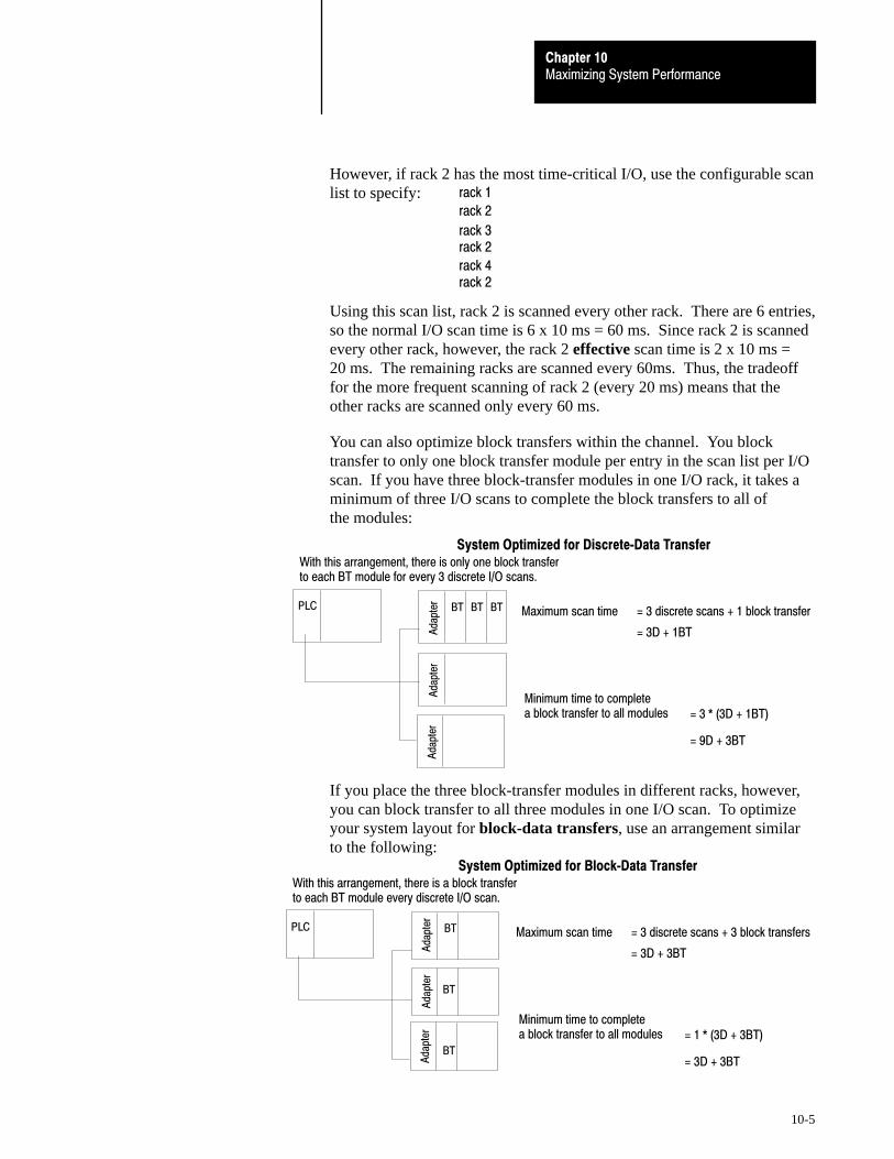
Chapter 10Maximizing System Performance
10-5
However, if rack 2 has the most time-critical I/O, use the configurable scanlist to specify:
Using this scan list, rack 2 is scanned every other rack. There are 6 entries,so the normal I/O scan time is 6 x 10 ms = 60 ms. Since rack 2 is scannedevery other rack, however, the rack 2 effective scan time is 2 x 10 ms =20 ms. The remaining racks are scanned every 60ms. Thus, the tradeofffor the more frequent scanning of rack 2 (every 20 ms) means that theother racks are scanned only every 60 ms.
You can also optimize block transfers within the channel. You blocktransfer to only one block transfer module per entry in the scan list per I/Oscan. If you have three block-transfer modules in one I/O rack, it takes aminimum of three I/O scans to complete the block transfers to all of the modules:
PLC
Ada
pter BT BT BT
Ada
pter
Ada
pter
With this arrangement, there is only one block transferto each BT module for every 3 discrete I/O scans.
Maximum scan time
Minimum time to complete a block transfer to all modules
= 3 discrete scans + 1 block transfer
= 3D + 1BT
= 3 * (3D + 1BT)
= 9D + 3BT
System Optimized for Discrete�Data Transfer
If you place the three block-transfer modules in different racks, however,you can block transfer to all three modules in one I/O scan. To optimizeyour system layout for block-data transfers, use an arrangement similarto the following:
PLC
Ada
pter BT
BT
Ada
pter
Ada
pter
With this arrangement, there is a block transferto each BT module every discrete I/O scan.
Maximum scan time
Minimum time to complete a block transfer to all modules
= 3 discrete scans + 3 block transfers
= 3D + 3BT
= 1 * (3D + 3BT)
= 3D + 3BTBT
System Optimized for Block�Data Transfer
rack 1
rack 2
rack 3
rack 4
rack 2
rack 2

Chapter 10Maximizing System Performance
10-6
The processor time is the time needed to process the inputs and set thecorresponding outputs. This processor time varies for different processorsand is based on input buffering, program scan, etc.
In a PLC-5 system, both inputs and outputs are buffered between the I/Oimage table and the I/O scanner. The movement of inputs from the scannerto the input buffer is asynchronous to the movement of data from the inputbuffer to the input image table. The worst-case processor time is:
Periodic input buffer update
One program scan to guarantee inputs received
.18 ms times the number of racks
= 10 ms
= xx ms
= xx ms
One program scan to guarantee outputs received = xx ms
For a 3-rack system with a 20 ms program scan, the worst-case processortime is: 10 + 20 + 20 + .54 = 50.54 ms.
To calculate throughput, use the following equation:
InputCardDelay
I/O Backplane Worst�CaseRemote I/OScan Time
Worst�CaseProcessorTime
+ + + Worst�CaseRemote I/OScan Time
+ I/O Backplane+OutputCardDelay
+
An example of a worst-case update time calculation:
Input card delay
I/O backplane
Worst�case remote I/O scan time
Worst�case processor time
Worst�case remote I/O scan time
I/O backplane
Output card delay
= 20 ms (typical)
= 1 ms
= 30 ms
= 50.54 ms
= 30 ms
= 1 ms
= 8.8 ms (typical)
Total 141.34 ms
Processor Time
Calculating Throughput

Appendix
A
A-1
Selecting Switch Settings
Make the following switch selections for Classic PLC-5 processors.
1. Regardless of this switch setting, outputs are reset when either of the following occurs:
• processor detects a runtime error
• an I/O chassis backplane fault occurs
• you select program or test mode
• you set a status file bit to reset a local rack
2. If an EEPROM module is not installed and processor memory is valid, the processor's PROC LED indicator blinks,and the processor sets S:11/9, bit 9 in the major fault status word.
3. A processor fault occurs if processor memory (solid red PROC LED) is not valid.
4. You cannot clear processor memory when this switch is on
4 5
2 -slot
1 -slot
1/2- slot
1
AlwaysOff
19309
6 7
Outputs of this I/O chassis remain in their last state whena hardware failure occurs. 1
Outputs of this I/O chassis are turned off when ahardware failure occurs. 1
Pressed in at top ON (closed)
Pressed in at bottom OFF (open)
EEPROM memory transfer to processor memory at powerup. 2
EEPROM memory transfers to processor memory if processor memorynot valid.
EEPROM memory does not transfer to processor memory. 3
RAM memory protection disabled.
RAM memory protection enabled. 4
Not allowed
RAM Memory ProtectionSwitch
8
OFF
ON
EEPROM Transfer
Addressing
Last StateSwitch
ON
OFF
Switches
Switches
OFF OFF
OFF ON
ON OFF
ON ON
OFF OFF
ON ON
ON OFF
Chassis Backplane withClassic PLC�5 Processor

Selecting Switch SettingsAppendix A
A-2
Make the following switch selections for a 1771-AS, -ASB, or -ALXadapter module.
Switch
Switch
5 6
1
2
ON
OFF
Last State
Switches
Processor Restart Lockout
Addressing
Outputs of this I/O chassis remain in their last state when a communication fault isdetected by this I/O adapter. 1
Outputs of this I/O chassis are turned off when a comunication fault is detectedby this I/O adapter.
Processor can restart the I/O chassis after a communication fault. 2
You must manually restart the I/O chassis with a switch wired to the1771�AS or �ASB.
ON
ON
ON ON
ON
OFF
OFF OFF
OFF
OFF
2�slot
1�slot 3
1/2�slot 3
Not allowed
Pressed in at top Closed (ON)
Pressed in at bottom Open (OFF)
Always Off
Always Off
19308
1. ATTENTION: If you set this switch to the ON position, when a communication fault is detected, outputs connected to this chassis remain in their last state to allow machine motion to continue. We recommed that you set switch 1 to the OFF position to de�energize outputs wired to this chassis when a fault is detected.
Also, if outputs are controlled by inputs in a different rack and a remote I/O rack fault occurs (in the inputs rack), the inputs are left in their last non�faulted state. The outputs may not be properly controlled and potential personnel and machine damage may result. If you want your inputs to be anything other than their last non�faulted state, then you need to program a fault routine.
2. Set this switch to ON if you plan to use I/O rack auto�configuration.
3. The 1771�ASB series A adapter does not support 1/2�slot addressing.
Chassis Backplane withAdapter Module

Selecting Switch SettingsAppendix A
A-3
Position the configuration plug for the power supply you add to your chassis.
USING POWER SUPPLYMODULE IN THE CHASSIS?
1. Locate the chassis configuration plug (betweenthe first two left most slots of the chassis).
2. Set the I/O chassis configuration plug.
The default setting is N (not using a powersupply module in the chassis).
NY
NYNY
Set Y when you installa power supply modulein the chassis.
Set N when youuse an externalpower supply.
IMPORTANT: You cannot power a single I/O chassiswith both a power supply module and an externalpower supply.
17075
Chassis Configuration Plugfor Power Supply

Selecting Switch SettingsAppendix A
A-4
Select the switches to determine I/O rack, group, transmission rate, linkresponse, and scan for your adapter module without complementary I/O.
1 2 3 4ON
OFF
SW–2
1 2 3 4 5 6 7 8ON
OFF
SW–1
5 6
Switch
1 2
ON
OFF
OFF
ON
OFF
OFF
ON
ON
57.6 Kbps10,000 ft
115.2 Kbps5,000 ft
230.4 Kbps2,500 ft
Not used
Maximum Chassis
Distance
Pressed in at top Closed (ON)
Pressed in at bottom Open (OFF)
I/O Rack Number(see next page)
First I/O Group Number (see below)
Link Response: ONfor series B emulation OFFfor unrestricted
Scan: ONfor all but last 4 slotsOFFfor all slots
on = closedoff = open
First I/O GroupNumber
7 8
0 on on
2 on off
4 off on
6 off off
Remote I/O Adapter Module1771�ASB Series C withoutComplementary I/O

Selecting Switch SettingsAppendix A
A-5
Remote I/O Adapter Module (1771�ASB Series C) I/O RackNumberwithout Complementary I/O
Rack 1 2 3 4 5 6
01 on on on on on off
02 on on on on off on
03 on on on on off off
04 on on on off on on
05 on on on off on off
06 on on on off off on
07 on on on off off off
10 on on off on on on
11 on on off on on off
12 on on off on off on
13 on on off on off off
14 on on off off on on
15 on on off off on off
16 on on off off off on
17 on on off off off off
20 on off on on on on
21 on off on on on off
22 on off on on off on
23 on off on on off off
24 on off on off on on
25 on off on off on off
26 on off on off off on
27 on off on off off off
PLC�5/15 processorsracks 01�03;
PLC�5/25 processorsracks 01�07;

Selecting Switch SettingsAppendix A
A-6
Select the switches to determine I/O rack, group, transmission rate, linkresponse, and scan for your adapter module using complementary I/O.
ONPrimary ChassisOFFComplementary Chassis
1 2 3 4 5 6 7 8ON
OFF
S W -1
1 2 3 4ON
OFF
SW–2
5 6
Switch
1 2
ON
OFF
OFF
ON
OFF
OFF
ON
ON
57.6 Kbps10,000 ft
115.2 Kbps5,000 ft
230.4 Kbps2,500 ft
not used
Maximum Chassis
Distance
ONscans for all but 4 last slots
OFFscans for all slots
OFFfor unrestricted
ONPrimary Chassis
OFFComplementary Chassis
I/O Rack Number
First I/O Group Number
Pressed in at top Closed (ON)
Pressed in at bottom Open (OFF)
Link Response: ONfor series B emulation
I/O Rack Number 4 5 6
1 on on off
2 on off on
3 on off off
41 off on on
51 off on off
61 off off on
71 off off off
1 Valid for PLC�5/25 processors only. Only seven racks can be
complemented in a PLC�5 system.
For First I/O GroupNumber
7 8
0 on on
2 on off
4 off on
6 off off
Remote I/O Adapter Module1771�ASB Series C withComplementary I/O

Selecting Switch SettingsAppendix A
A-7
Set SW1 switch assembly switches 1 through 6 for the DH+ stationnumber. Switch 7 is not used. Set switch 8 for scanner or adapter mode.
1 2 3 4 5 6 7 8
S w itch A ssem bly S W 1
Top V iew of M odu le
toggle pushed
on (closed)
toggle pushed
off (open)
Side View
toward bottom
toward top
To select: Set switch: To:
DH+ Station Number 1 through 6 (see below)
Switch 7 not used 7 off
Scanner mode 8 off
Adapter 8 on
StationNumber
012345671011121314151617202122232425
1
onoffonoffonoffonoffonoffonoffonoffonoffonoffonoffonoff
2
ononoffoffononoffoffononoffoffononoffoffononoffoffonon
3
ononononoffoffoffoffononononoffoffoffoffononononoffoff
4
ononononononononoffoffoffoffoffoffoffoffonononononon
5
ononononononononononononononononoffoffoffoffoffoff
6
onononononononononononononononononononononon
424344454647505152
onoffonoffonoffonoffon
offoffononoffoffononoff
ononoffoffoffoffononon
ononononononoffoffoff
ononononononononon
offoffoffoffoffoffoffoffoff
Switch
StationNumber
535455565760616263646566677071727374757677
1
offonoffonoffonoffonoffonoffonoffonoffonoffonoffonoff
2
offononoffoffononoffoffononoffoffononoffoffononoffoff
3
onoffoffoffoffononononoffoffoffoffononononoffoffoffoff
4
offoffoffoffoffononononononononoffoffoffoffoffoffoffoff
5
onononononoffoffoffoffoffoffoffoffoffoffoffoffoffoffoffoff
6
offoffoffoffoffoffoffoffoffoffoffoffoffoffoffoffoffoffoffoffoff
Switch
26273031323334353637
4041
onoffonoffonoffonoffonoff
onoff
offoffononoffoffononoffoff
onon
offoffononononoffoffoffoff
onon
ononoffoffoffoffoffoffoffoff
onon
offoffoffoffoffoffoffoffoffoff
onon
onononononononononon
offoff
DH+DH+
SW1

Selecting Switch SettingsAppendix A
A-8
Set SW2 switch assembly switches for an adapter-mode PLC-5 processorin a PLC-5 processor or scanner module. Set switches 2 through 8 fornumber of words communicated from the host processor to the adapterprocessor, for the I/O group, and for the rack number of the I/O group ofthe adapter processor, respectively. Switch 1 is unused.
1 2 3 4 5 6 7 81 2 3 4
Bottom View of Module Switch Assembly SW2
Switch Assembly SW3
toggle pushed
on (closed)
toggle pushed
off (open)
Side View
toward bottom
toward top
If you want: Set switch: To:
Switch 1 is always unused. 1 off
The host processor to use 8 words to communicate with the adapter PLC�5 processor 2 off
The host processor to use 4 words to communicate with the adapter PLC�5 processor 2 on
First I/O group to be 0 3 on
First I/O group to be 4 3 off
Select the I/O rack number of the adapter PLC�5 processor 4 through 8 see table below
Rack 4 5 6 7 8 Rack 4 5 6 7 8
01 on on on on off 15 on off off on off
02 on on on off on 16 on off off off on
03 on on on off off 17 on off off off off
04 on on off on on 20 off on on on on
05 on on off on off 21 off on on on off
06 on on off off on 22 off on on off on
07 on on off off off 23 off on on off off
10 on off on on on 24 off on off on on
11 on off on on off 25 off on off on off
12 on off on off on 26 off on off off on
13 on off on off off 27 off on off off off
14 on off off on on
Adapter�ModeProcessorsSW2 in aPLC�5 or Scanner Module

Selecting Switch SettingsAppendix A
A-9
Set SW2 switch assembly switches for an adapter-mode PLC-5 processorin a PLC-2/20 or -2/30 processor system or sub I/O scanner modulesystem. Set switches 2 through 8 for the number of words communicatedfrom host processor to adapter processor, for the I/O group, and for therack number of the I/O group of the adapter processor, respectively.Switch 1 is unused.
1 2 3 4 5 6 7 81 2 3 4
Bottom View of Module Switch Assembly SW2
Switch Assembly SW3
toggle pushed
on (closed)
toggle pushed
off (open)
Side View
toward bottom
toward top
If you want: Set switch: To:
Switch 1 is always unused. 1 off
The host processor to use 8 words to communicate with the adapter PLC�5 2 off
The host processor to use 4 words to communicate with the adapter PLC�5 2 on
First I/O group to be 0 3 on
First I/O group to be 4 3 off
Select the I/O rack number of the adapter PLC�5 processor 4 through 8 see below
Rack 4 5 6 7 8
01 on on on on on
02 on on on on off
03 on on on off on
04 on on on off off
05 on on off on on
06 on on off on off
07 on on off off on
Adapter�ModeProcessorsSW2 in aPLC�2/20, �2/30, or Sub I/OScanner Module System

Selecting Switch SettingsAppendix A
A-10
Set SW2 switch assembly switches for an adapter-mode PLC-5 processorin a PLC-3 or PLC-5/250 processor system. Set switch 2 for the number ofwords communicated from host processor to the adapter processor. Setswitches 3 through 8 for the I/O rack number of the adapter processor.Switch 1 is unused.
1 2 3 4 5 6 7 81 2 3 4
Bottom View of Module Switch Assembly SW2
Switch Assembly SW3
toggle pushed
on (closed)
toggle pushed
off (open)
Side View
toward bottom
toward top
If you want: Set switch: To:
Switch 1 is always unused. 1 off
The host processor to use 8 words to communicate with the adapter PLC�5 processor 2 off
Select the I/O rack number of the adapter PLC�5 processor 3 through 8 see below
0
1
2
3
4
5
6
7
10
11
12
13
14
15
16
17
20
21
22
23
24
25
26
27
30
31
32
33
34
35
36
37
40
41
on
on
on
on
on
on
on
on
on
on
on
on
on
on
on
on
on
on
on
on
on
on
on
on
on
on
on
on
on
on
on
on
off
off
4
on
on
on
on
on
on
on
on
on
on
on
on
on
on
on
on
off
off
off
off
off
off
off
off
off
off
off
off
off
off
off
off
on
on
6
on
on
on
on
off
off
off
off
on
on
on
on
off
off
off
off
on
on
on
on
off
off
off
off
on
on
on
on
off
off
off
off
on
on
5
on
on
on
on
on
on
on
on
off
off
off
off
off
off
off
off
on
on
on
on
on
on
on
on
off
off
off
off
off
off
off
off
on
on
7
on
on
off
off
on
on
off
off
on
on
off
off
on
on
off
off
on
on
off
off
on
on
off
off
on
on
off
off
on
on
off
off
on
on
8
on
off
on
off
on
off
on
off
on
off
on
off
on
off
on
off
on
off
on
off
on
off
on
off
on
off
on
off
on
off
on
off
on
off
42
43
44
45
46
47
50
51
52
8
on
off
on
off
on
off
on
off
on
7
off
off
on
on
off
off
on
on
off
6
on
on
off
off
off
off
on
on
on
5
on
on
on
on
on
on
off
off
off
4
on
on
on
on
on
on
on
on
on
3
off
off
off
off
off
off
off
off
off
SwitchSwitch
53
54
55
56
57
60
61
62
63
64
65
66
67
70
71
72
73
74
75
76
8
off
on
off
on
off
on
off
on
off
on
off
on
off
on
off
on
off
on
off
on
7
off
on
on
off
off
on
on
off
off
on
on
off
off
on
on
off
off
on
on
off
6
on
off
off
off
off
on
on
on
on
off
off
off
off
on
on
on
on
off
off
off
5
off
off
off
off
off
on
on
on
on
on
on
on
on
off
off
off
off
off
off
off
4
on
on
on
on
on
off
off
off
off
off
off
off
off
off
off
off
off
off
off
off
3
off
off
off
off
off
off
off
off
off
off
off
off
off
off
off
off
off
off
off
off
Switch
I/ORackNo.
I/ORackNo.
I/ORackNo.3
Adapter�ModeProcessorsSW2 in aPLC�3 or PLC�5/250 Systemwith 8�Word Groups

Selecting Switch SettingsAppendix A
A-11
Set SW2 switch assembly switches for an adapter-mode PLC-5 processorin a PLC-3 or PLC-5/250 processor system. Set switch 2 for the number ofwords communicated from the host processor to the adapter processor. Setswitch 3 for I/O group. Set switches 4 through 8 for the I/O rack numberof the adapter processor. Switch 1 is unused.
1 2 3 4 5 6 7 81 2 3 4
Bottom View of Module Switch Assembly SW2
Switch Assembly SW3
toggle pushed
on (closed)
toggle pushed
off (open)
Side View
toward bottom
toward top
If you want: Set switch: To:
Switch 1 is always unused. 1 off
The host processor to use 4 words to communicate with the adapter PLC�5 processor 2 on
First I/O group to be 0 3 on
First I/O group to be 4 3 off
Select the I/O rack number of the adapter PLC�5 processor 4 through 8 see below
I/O RackNumber
0123456710111213141516
4
ononononononononononononononon
6
ononononoffoffoffoffononononoffoffoff
5
ononononononononoffoffoffoffoffoffoff
7
ononoffoffononoffoffononoffoffononoff
8
onoffonoffonoffonoffonoffonoffonoffon
Switch
I/O RackNumber
17
20212223242526273031323334353637
4
on
offoffoffoffoffoffoffoffoffoffoffoffoffoffoffoff
6
off
ononononoffoffoffoffononononoffoffoffoff
5
off
ononononononononoffoffoffoffoffoffoffoff
7
off
ononoffoffononoffoffononoffoffononoffoff
8
off
onoffonoffonoffonoffonoffonoffonoffonoff
Switch
Adapter�ModeProcessorsSW2 in aPLC�3 or PLC�5/250 Systemwith 4�Word Groups

Selecting Switch SettingsAppendix A
A-12
Set SW3 switch assembly switches to terminate either a DH+ link or aremote I/O link. Switches 3 and 4 are unused.
1 2 3 4 5 6 7 81 2 3 4
Bottom View of Module
Switch Assembly SW3
toggle pushed
on (closed)
toggle pushed
off (open)
Side View
toward bottom
toward top
If the processor is: Set switch: To:
An end device on the remote I/O link 1 on
Not an end device on the remote I/O link 1 off
An end device on the DH+ link 2 on
Not an end device on the DH+ link 2 off
Switch 3 unused 3 off
Switch 4 unused 4 off
SW3

Appendix
B
B-1
Design Worksheets
The following symbols are printed in the top left corner of the worksheets.The symbols indicate whether programmers or installers will need thecompleted worksheets. Use the symbols as a way of organizing thecompleted worksheets for the appropriate user.
indicates a worksheet that provides information for a programmer
indicates a worksheet that provides information for an installer
BOM
indicates a worksheet that provides information for a bill of materials (BOM)
Important: You may need to make multiple copies of some worksheets torecord all of your system requirements.
Conventions Used in
These Worksheets

Design WorksheetsAppendix B
B-2
Prepare a Functional Specification
For more information on: See:
Functional specifications Classic 1785 PLC�5 Programmable Controllers User Manual, publication 1785�6.2.1, Chapter 1:Designing Systems Preparing Your Functional Specification
1. Divide your manufacturing process into functional areas.
2. Make a copy of the reverse side of this worksheet for each functional area.
3. For each functional area, document the following:
Information to Document Example(s)
Inputs Actions and signals, ranges, quantities, timing, tolerance, units of measure, validationrequirements, possible errors, and error responses
Outputs Quantities, units of measure, timing, tolerances, ranges, validation methods, methodor reporting invalid outputs, locations, methods of data output, physical requirements
Performance requirements Accuracy; maximum and minimum transition times; interface timing; operatorresponse timing; adherence to standards such as IEEE, ANSI
Interfaces Operator, software, hardware
Failure modes and recovery methods Fault routines
Security requirements Operator access, alarming, etc.
Maintenance requirements Documentation, spare parts, accessibility
4. Use the information on these worksheets to develop a complete functional specification.
Design WorksheetsAppendix B
B-3
Functional Area:
Inputs:
Outputs:
Performance Requirements:
Interfaces:
Failure Modes and Recovery Methods:
Security Requirements:
Maintenance Requirements:

Design WorksheetsAppendix B
B-4
Determine Control Strategy
For more information on: See:
Control strategyRemote I/O scanner modeExtended�local I/O scanner modeRemote I/O adapter mode
Classic 1785 PLC�5 Programmable Controllers User Manual, publication 1785�6.2.1,Chapter 1: Designing Systems Using the Classic PLC�5 Processor as a Remote I/O Scanner
Using the Classic PLC�5 Processor as a Remote I/O Adapter
Choosing communication Classic 1785 PLC�5 Programmable Controllers Design Manual, publication 1785�6.2.1,Chapter 5
1. Answer the following questions when you begin planning your control strategy:
What will be controlled together?
What will be controlled separately?
Will control devices communicate as peers (network) or in a hierarchy (master/slave)?

Design WorksheetsAppendix B
B-5
What will be controlled via a remote I/O link?
Which processes will be controlled by a classic 1785 PLC-5 processor?
What are the environmental and safety concerns for your system?
2. Use text and illustrations to lay out and describe your strategy.

Design WorksheetsAppendix B
B-6
Identify Chassis Locations
1. Make a copy of this worksheet for each of your functional areas.
2. For each functional area, determine the number of chassis by using the table below.
Functional Area:
Category Number ofChassis
Each functional area requires at least one chassis. 1
Add an additional chassis for each case where I/O at this functional area require different:
power disconnects
ac phases
logical or functional groupings
Total chassis for this functional area:
3. Assign a unique chassis number to each of the chassis, and record all assigned numbers below.
Chassis ______________ Chassis ______________
Chassis ______________ Chassis ______________
Chassis ______________ Chassis ______________
Chassis ______________ Chassis ______________
Chassis ______________ Chassis ______________
Chassis ______________ Chassis ______________
Chassis ______________ Chassis ______________
Chassis ______________ Chassis ______________
Chassis ______________ Chassis ______________

Design WorksheetsAppendix B
B-7
Select Module Types and List I/O Points
For more information on: See:
Selecting I/O modulesSelecting I/O points
Classic 1785 PLC�5 Programmable Controllers User Manual, publication 1785�6.2.1, Chapter 2: Selecting I/O Modules
Selecting I/O Adapter Modules
I/O module catalog numbers Automation Products Catalog, publication AP 100, Section 3:Input/Output
1. Make a copy of the reverse side of this worksheet for each of your chassis.
2. For each chassis, list each discrete, analog, and specialty I/O module and its electricalcharacteristics. Use the table below to determine which characteristics to list.
If you choose this type of I/O module: List these characteristics:
Discrete input module
VoltageSpecial requirements:
- Isolation- Proximity switch- Source or sink- Fast response- TTL
Discrete output module
VoltageCurrentSpecial requirements:
- Isolation- Protection (detection of failed triacs)- TTL- High current switching
Analog input module
Voltage or current rangeResolution requiredSingle�ended or differentialSpecial requirements
- Thermocouple- RTD- Isolation
Analog output module
Voltage or current rangeResolution requiredSpecial requirements:
- PID- Isolation
Specialty or communication I/O modules (including block I/O modules)
Voltage or current rangeResolution requiredNoise/distance limitsSingle�ended or differentialSpecial requirements
- Thermocouple- RTD- PID- Isolation
BOM

Design WorksheetsAppendix B
B-8
Chassis Number: _____________________
Input orOutput
I/O Module Type I/O ModuleCatalogNumber
TimeCriticalYes / No
Voltage orRange
Currentor Range
Numberof Points
RequiredResolution
(analog only)
Single�Endedor Differential(analog only)
SpecialRequirements

Design WorksheetsAppendix B
B-9
Total I/O Module Requirements
1. Make a copy of this worksheet for each of your chassis.
2. For each of the I/O modules identified on the chassis’ Select Module Types and List I/O Pointsworksheet on pages 7 and 8, perform the following steps to determine the total number that youneed.
3. In column A, list the module’s catalog number.
4. In column B, total the number of I/O points for the module.
5. In column C, enter the maximum number of I/O points available per module.
6. In column D, calculate the total number of these modules that you will need for this chassisby dividing column B by column C.
7. In column E, enter the number of spare modules that you may need for future expansion of this chassis.
8. In column F, enter the total number of these modules that you need for this chassis.
Chassis Number: _________________
AI/O Module Cat. No.
BTotal I/O Points
CI/O Points / Module
DI/O Modules Required(B / C)
ESpare I/O modules
FTotal I/O modules
BOM

Design WorksheetsAppendix B
B-10
Assign I/O Modules to Chassis and Assign Addresses
For more information on: See:
Assigning I/O modules to chassisSelecting addressing modeAssigning addressesAddressing complementary I/O
Classic 1785 PLC�5 Programmable Controllers User Manual, publication 1785�6.2.1, Chapter 4: Placing I/O Modules in Chassis Choosing the Addressing Mode Assigning Racks
Addressing Complementary I/O
Selecting the I/O chassis Classic 1785 PLC�5 Programmable Controllers Design Manual, publication 1785�6.2.1, Chapter 2: Selecting I/O Chassis
Current requirements to I/O modules Automation Products Catalog, publication AP 100, Section 3:Input/Output
9. Make a copy of the reverse side of this worksheet for each of your chassis, and use it to recordyour responses to items 2 through 8.
10. Indicate the addressing mode for each chassis. Use the table below to guide your selection.
If the densest I/O module in the chassis is: And you want to: Then choose:
8�point 2�slot addressing
16�pointAssign any mix of modules in adjacent module slots 1�slot addressing
16�pointMake full use of I/O capacity 2�slot addressing
32�pointAssign any mix of modules in adjacent module slots 1/2�slot addressing
32�pointMake full use of I/O capacity 1�slot addressing
11. Indicate the chassis size. Use the table below to guide your selection.
If you need to: And are: Then consider:
Reduce spare partsExpanding your system Standard size you now use
Reduce spare partsInstalling a new system One size using the guidelines listed below
Limited to 9 inches 4�slot chassis
Fit space requirementsLimited to 14 inches 8�slot chassis
Fit space requirementsLimited to 19 inches 12�slot chassis
Limited to 24 inches 16�slot chassis
Minimize scan time Largest chassis containing processor
Minimize cost per slotLargest chassis consistent with decisions above
Accommodate expansionLargest chassis consistent with decisions above
12. Indicate whether a processor or an adapter is in the left-most slot.
13. Indicate whether you are using this chassis for complementary I/O.
14. Write the module type in each available slot on the chassis diagram.
15. Assign rack numbers, group numbers, and number of points per group.
16. Indicate the current requirement for each module.
BOM

Design WorksheetsAppendix B
B-11
1771�A1B4�slot chassis
1771�A2B8�slot chassis
1771�A3B, or1771�A3B112�slot chassis
1771�A4B16�slot chassis
IndicateChassisSize:
R___ R___ R___ R___ R___ R___ R___ R___
Addressing Mode: 2�slot 1�slot 1/2�slotChassis Number: _________________
Processor Complementary I/O? Yes, chassis______ NoAdapteror
G ___
00-0710-17
G __
00-07
10-17
Slot 1
G ___
00-0710-17
G __
00-07
10-17
Slot 2
G ___
00-0710-17
G __
00-07
10-17
Slot 3
G ___
00-0710-17
G __
00-07
10-17
Slot 4
G ___
00-0710-17
G __
00-07
10-17
Slot 5
G ___
00-0710-17
G __
00-0710-17
Slot 6
G ___
00-0710-17
G __
00-07
10-17
Slot 7
G ___
00-0710-17
G __
00-07
10-17
Slot 8
List CurrentRequired forEach Module inthis Chassis:
Identify Groupsand I/O Points:
____
____
____
____
____
____
____
____
____
____
____
____
____
____
____
____
Total Current Draw for I/O Modules in this Chassis = _____
G ___
00-0710-17
G __
00-07
10-17
Slot 9
G ___
00-0710-17
G __
00-07
10-17
Slot 10
G ___
00-0710-17
G __
00-07
10-17
Slot 11
G ___
00-0710-17
G __
00-07
10-17
Slot 12
G ___
00-0710-17
G __
00-07
10-17
Slot 13
G ___
00-0710-17
G __
00-0710-17
Slot 14
G ___
00-0710-17
G __
00-07
10-17
Slot 15
G ___
00-0710-17
G __
00-07
10-17
Slot 16

Design WorksheetsAppendix B
B-12
Select Adapter Modules
For more information on: See:
Selecting the I/O adapter modules Classic 1785 PLC�5 Programmable Controllers User Manual, publication 1785�6.2.1, Chapter 2: Selecting I/O Adapter Modules
17. In column A of the table below, indicate the chassis number in which you will place each adapter module.
18. In column B, indicate the name/type of each adapter module.
19. In column C, list any special requirements for the adapter module.
20. In column D, indicate the current draw requirements for the adapter module.
AChassis Number
BAdapter Module
CSpecial Requirements
DCurrent Draw
BOM

Design WorksheetsAppendix B
B-13
21. In the table below, list any device other than an adapter module that you are connecting to aremote I/O link, list its chassis number, and list any special requirements. For example:
PLC-5 processor in adapter mode PLC-5/250 remote scanner in adapter mode PLC interface module for digital ac and dc drives Remote I/O adapter for Bulletin 1336 drives RediPANEL pushbutton and keypad modules Dataliner PanelView (see operator interface) Option module (for T30 plant-floor terminal) 8600 CNC with remote I/O adapter option CVIM in adapter mode Pro-Spec 6000 Fastening System with remote I/O adapter option 1747-DCM module (to SLC-500 rack) 1771-DCM module 1771-GMF robot (remote I/O interface module)
Device Attached to Chassis Number Special Requirements

Design WorksheetsAppendix B
B-14
Place System Hardware
For more information on: See:
Determining proper environmentEnclosuresRaceway layoutCabling and wiringMountingGrounding
Classic PLC�5 Programmable Controllers User Manual, publication 1785�6.2.1, Chapter 3: Determining the Proper Environment Protecting Your Processor Laying Out Your Cable Raceway Planning Cabling
Laying Out the Backpanel Spacing Grounding Configuration
Sketch a layout of your system that indicates the following:
proper environment enclosures mounting raceway layout cabling and wiring grounding

Design WorksheetsAppendix B
B-15
Configure Switch Settings
For more information on: See:
Configuring switches Classic PLC�5 Programmable Controllers User Manual, publication 1785�6.2.1, Appendix A
Record switch setting choices on a copy of this worksheet. You might need to return to the worksheetseveral times as you complete your system design.
USING POWER SUPPLYMODULE IN THE CHASSIS?
1. Locate the chassis configuration plug (between thefirst two left most slots of the chassis).
2. Set the I/O chassis configuration plug.
The default setting is N (not using a power supplymodule in the chassis).
NY
NYNY
Set Y when you installa power supply modulein the chassis.
Set N when youuse an externalpower supply.
IMPORTANT: You cannot power a single I/O chassiswith both a power supply module and an externalpower supply.
17075
Rack 0 Chassis and Processor Switch Settings
For PLC�5/10, �5/12, �5/15, �5/25 processors:
Rack 0
Processor Chassis Back Plane Switches
Processor Module Switch SW1
Processor Module Switch SW2
Processor Module Switch SW3OFF ON
Notes: Switches shown in black are not used, but they must be set to the positions indicated.
ON ON
1 2 3 4 5 6 7 8ON
OFF
1 2 3 4 5 6 7 8OFF
ON
1 2 3 4 5 6 7 8OFF
ON
1 2 3OFFON
4

Design WorksheetsAppendix B
B-16
1 2 3 4 5 6 7 8ON
OFF
Chassis and Adapter Switch Settings for Remote I/O
Rack______
1 2 3 4 5 6 7 8ON
OFF
1 2 3 4ON
OFF
I/O Chassis Back Plane Switches
Adapter Module Switch SW1
Adapter Module Switch SW2Series C
OFF
Note: Switches previously marked in black are not used, but must be set to the positions indicated.
Rack______
I/O Chassis Back Plane Switches
Adapter Module Switch SW1
Rack______
I/O Chassis Back Plane Switches
Adapter Module Switch SW1
Rack______
I/O Chassis Back Plane Switches
Adapter Module Switch SW1
Rack______
I/O Chassis Back Plane Switches
Adapter Module Switch SW1
Rack______
I/O Chassis Back Plane Switches
Adapter Module Switch SW1
Rack______
I/O Chassis Back Plane Switches
Adapter Module Switch SW1
5 61 2 3ON
OFF
Adapter Module Switch SW2Series B
Adapter Module Switch SW2Series B
Adapter Module Switch SW2Series B
Adapter Module Switch SW2Series B
Adapter Module Switch SW2Series B
Adapter Module Switch SW2Series B
Adapter Module Switch SW2Series B
OR
Adapter Module Switch SW2Series C
Adapter Module Switch SW2Series C
Adapter Module Switch SW2Series C
Adapter Module Switch SW2Series C
Adapter Module Switch SW2Series C
Adapter Module Switch SW2Series C
OR
OR
OR
OR
OR
4
1 2 3 4 5 6 7 8ON
OFF
1 2 3 4 5 6 7 8ON
OFF
1 2 3 4ON
OFF
5 61 2 3ON
OFF
4
1 2 3 4 5 6 7 8ON
OFF
1 2 3 4 5 6 7 8ON
OFF
1 2 3 4ON
OFF
5 61 2 3ON
OFF
4
1 2 3 4 5 6 7 8ON
OFF
1 2 3 4 5 6 7 8ON
OFF
1 2 3 4ON
OFF
5 61 2 3ON
OFF
4
1 2 3 4 5 6 7 8ON
OFF
1 2 3 4 5 6 7 8ON
OFF
1 2 3 4ON
OFF
5 61 2 3ON
OFF
4
1 2 3 4 5 6 7 8ON
OFF
1 2 3 4 5 6 7 8ON
OFF
1 2 3 4ON
OFF
5 61 2 3ON
OFF
4
1 2 3 4 5 6 7 8ON
OFF
1 2 3 4 5 6 7 8ON
OFF
1 2 3 4ON
OFF
5 61 2 3ON
OFF
4

Design WorksheetsAppendix B
B-17
Determine Communication Requirements
For more information on: See:
Identifying processor connectors/channelsConfiguring Channel 0 (serial ASCII port)Choosing a DH+ link
Classic 1785 PLC�5 Programmable Controllers User Manual, publication 1785�6.2.1,Chapter 5: Identifying Classic PLC�5 Processor Channels/Connectors Using Channel 0
Configuring a DH+ Link
Selecting DH+ cabling, layoutSelecting processor connectors/channels cabling
Classic 1785 PLC�5 Programmable Controllers Design Manual, publication 1785�6.2.1,Chapter 3: Laying Out Your Cable Raceway Planning Cabling
Selecting termination resistors Classic PLC�5 Programmable Controllers Design Manual, publication 1785�6.2.1, Chapter 2:Selecting Link Terminators
Defining DH+ station addresses Classic PLC�5 Family Programmable Controller Hardware Installation Manual, publication 1785�6.6.1
1. Make a copy of appropriate pages of this worksheet for each of your processors.
2. Identify communication modes and network selections.
3. Indicate channel configurations and DH+ station addresses.
4. List racks attached to each channel/connector configured for remote I/O scanner or adapter mode.
5. Identify DH+ link cable layout (daisy chain or trunkline/dropline).
BOM

Design WorksheetsAppendix B
B-18
6. Select your data link cables. Circle or highlight your selections in the following tables.
With this transmission rate: Select this maximum cable length (1770�CD cable):
57.6 kbaud 10,000 ft
115.2 kbaud 5,000 ft
230.4 kbaud 2,500 ft
If you need this: Select this catalog number:
Thick�wire 2.0 m (6.5 ft) transceiver cable 5810�TC02/A
Thick�wire 15.0 m (49.2 ft) transceiver cable 5810�TC15/A
Thin�wire transceiver, and 2.0 m (6.5 ft) cable 5810�TAS/A (kit)
Thin�wire transceiver, and 15.0 m (49.2 ft) cable 5810�TAM/A (kit)
Thick�wire transceiver, and 2.0 m (6.5 ft) cable 5810�TBS/A (kit)
Thick�wire transceiver, and 15.0 m (49.2 ft) cable 5810�TBM/A (kit)
7. Terminate a DH+ or remote I/O link by setting switch assembly 3.
for remote I/O link
for Ethernet link

Design WorksheetsAppendix B
B-19
C O M M B A T T
P R O C
F O R C E
FAULT
ACTIVERUN
R E M
RUN
PROG
B A T T E R YIN S T A LLE D
P E E RC O M MIN T F C
P E E RC O M MIN T F C
1S H2
PLC�5/10 Processor
List information:
List local rack numbers:
DH+ Station Address _______________
PLC�5/10PROGRAMMABLE CONTROLLER
Record any additional information about your communication mode and network selection.

Design WorksheetsAppendix B
B-20
C O M M B A T T
R E M I/O
A D P T
P R O C
F O R C E
FAULT
ACTIVERUN
R E M
RUN
PROG
B A T T E R YIN S T A LLE D
DH+
R E MI/O
1S H2
1S H2
PLC�5/12, �5/15, or �5/25 Processor
List information:
List rack numbers (ifconfigured for scanner):
SW1 settings
Scanner
Adapter
SW2 rack address setting
DH+ Station Address _______________
PLC�5/25PROGRAMMABLE CONTROLLER
DH+
First I/O group
Number of words totransfer
Record any additional information about your communication mode and network selection.

Design WorksheetsAppendix B
B-21
Select a Classic PLC�5 Processor
For more information on: See:
Selecting a processorSelecting optional memory modulesSelecting a replacement battery
Classic 1785 PLC�5 Programmable Controllers User Manual, publication 1785�6.2.1, Chapter 2: Choosing a Classic PLC�5 Processor for Your Application Selecting Memory Modules Selecting a Replacement Battery
Selecting a backup system PLC�5 Backup Communication Module User Manual, publication 1785�6.5.4
8. Make copies of both sides of this worksheet for each chassis that requires a processor.
9. For each chassis that requires a processor, use the table below to help you determine whichprocessor to use.
Total MemoryRequired
Total Numberof Racks
Total Numberof Chassis
Need a SerialPort?
Required ProgramScan Time
Total Numberof DH+ Ports
Total Number ofRemote I/O Ports
10. Record your Classic PLC-5 processor choice below.
Classic PLC-5 processor is: _______________________________
It will reside in chassis no.: _______________________________
The current required is: _______________________________
11. Select additional memory for your classic PLC-5 processor. Circle or highlight your selection inthe table below.
Nonvolatile Memory Backup (EEPROM) RAM Memory (CMOS)
Words Catalog Number (and Processor) Words Catalog Number (and Processor)
8 K 1785�MJ (PLC�5/10, �5/12, �5/15, �5/25) 4 K 1785�MR (PLC�5/15 and �5/25)
16 K 1785�MK (PLC�5/25) 8 K 1785�MS (PLC�5/15 and �5/25)
12. Select a 1770-XY, AA lithium replacement battery for your classic PLC-5 processor.
BOM

Design WorksheetsAppendix B
B-22
13. Select a backup system for your classic PLC-5 processor if required. A classic PLC-5 processorbackup system contains two of each of the following hardware components. Indicate yourselections below.
PLC-5 processor module (PLC-5/15 or -5/25 only)
1785-BCM module (for two channels)
1785-BEM module (for two additional channels)
power supply
local chassis

Design WorksheetsAppendix B
B-23
Select Power Supplies
For more information on: See:
Selecting power supplies Classic 1785 PLC�5 Programmable Controllers User Manual, publication 1785�6.2.1, Chapter 2: Selecting Power Supplies
Selecting power supply cables Automation Products Catalog, publication AP 100
1. Make a copy of this worksheet for each of your chassis.
2. Refer to the following worksheets for the values that you need to complete the formula to select apower supply.
Assign I/O Modules to Chassis and Assign Addresses worksheet for total I/O current draw Select Adapter Module or Select Classic PLC-5 Processor worksheet for current draw
3. Perform the following steps to calculate the total current required for chassis number____________ and to select a power supply.
On line A below, record the total backplane current draw for all I/O modules in the chassis. Ifyou leave slots available in your chassis for future expansion, add current draw for future I/Omodules.
On line B below, record the current draw required for the classic PLC-5 processor or the adaptermodule in the chassis.
On line C below, record the total current required from a power supply for that chassis.
A—Total I/O backplane current ____________________B—PLC-5 processor/adapter module current + ____________________C—Total backplane current required = ____________________
4. Choose your power supply dependent on the input voltage requirement and the total backplanecurrent required (line C above). Two types of power supplies are:
power supply modules—located in the same chassis as the PLC-5 processor or adapter module power supplies—located external to the chassis containing the PLC-5 processor or adapter
module
5. Record your power supply and cable choice below.
Power supply for this chassis is: _____________________________________Cable for this power supply is: _____________________________________
Important: You cannot use an external power supply and a power supply module to power thesame chassis; they are not compatible.

Design WorksheetsAppendix B
B-24
Choose a Programming Terminal
For more information on: See:
Selecting a programming terminalClassic 1785 PLC�5 Programmable Controllers User Manual, publication 1785�6.2.1, Chapter 2: Selecting a programming terminal
Selecting cables for a programming terminalChapter 2: Choosing Programming Terminals Choosing Cables
6. Make a copy of this worksheet for each of your PLC-5 processors.
7. Select a programming terminal for your Classic PLC-5 processor __________ located in chassisnumber _____________. Circle or highlight your selection in the table below.
Programming Terminal Operating System
• 6160�T53
• 6160�T60
• 6160�T70
• DOS 3.2, 3.3, 4.x, 5.0, or 6.0
8. Select a communication device and cables. Circle or highlight your selection in the table below.
If you have this device: With thiscommunication device:
Use this cable:
PLC�5/10, �5/12, �5/15, or �5/25 1784�KT, �KT2 1784�CPPLC 5/10, 5/12, 5/15, or 5/25 1784 KT, KT21784�KL, �KL/B
1784 CP
1784�KTK1 1784�CP5
1784�PCMK 1784�PCM5
6160�T60, 6160�T70, 6121 IBM PC/AT (or compatible) 1785�KE 1784�CAK
1784�T47, 6123, 6124IBM PC/XT (or compatible)
1785�KE 1784�CXK
6120, 6122 1785�KE 1784�CYK
BOM

Design WorksheetsAppendix B
B-25
Select Programming Terminal Configuration
1. Make a copy of this worksheet for each of your programming terminals.
2. Document your software configuration decisions below for your Classic PLC-5 processor__________ located in chassis number _____________.
DH+ connections:
Local access or remote network access ________________________________
Direct or multi-drop ________________________________
Type of interface card ________________________________
Unique station address assigned to terminal ________________________________
Bit address of KT board in programming terminal ________________________________

Design WorksheetsAppendix B
B-26
Select Operator Interface
For more information on: See:
Selecting an operator interface Classic 1785 PLC�5 Programmable Controllers User Manual, publication 1785�6.2.1, Chapter 2: Selecting an Operator Interface
Select your operator interface using the table that follows.
3. In column A, list the operator interface station.
4. In column B, list the required operator interface screens per station.
5. In column C, describe the information and control requirements for each screen.
6. In column D, list the reports that you want to generate.
AOperator InterfaceStation
BOperator InterfaceScreen(s)
CInformation and Control Requirements
DReports
BOM

Design WorksheetsAppendix B
B-27
AOperator InterfaceStation
DReports
CInformation and Control Requirements
BOperator InterfaceScreen(s)

Design WorksheetsAppendix B
B-28
Develop Programming Specifications
1. Use the following table to guide you in developing a programming design specification.
Design Specification Options Definition
Will you use SFCs?
What fault routines will you use?
2. Lay out your data table memory map.
3. Plan your ladder-logic program.
4. What testing will you perform?

Numbers
1/2�slot addressing, defined, 4�8
1770-KF2, 5�12
1770-XY, 2�13
1771�AS adapter module, selection, 2�4
1771�ALX adapter module, selection, 2�4, 2�5
1771�ASB adapter module, selection, 2�4
1784�KL, 5�11
1784�KT, 5�11
1785�BCM. See backup system
1785-KE, 5�12
1785-MJ, 2�13, B�21
1785-MK, 2�13, B�21
1785-MR, 2�13, B�21
1785-MS, 2�13, B�21
1785�BEM. See backup system
1�slot addressing, defined, 4�6
2�slot addressing, defined, 4�3
A
adapter modeadapter image file, PLC�5/12, �5/15, �5/25
processors, 8�4transferring data, 8�4
block transfers, 8�7block�transfer addressing tips, 8�8block�transfer programming example,
8�10default file for discrete�transfer data,
8�4determining processor status, 8�6determining status of supervisory
processor, 8�6transferring bits with supervisory
processor, 8�5using processor as a remote I/O adapter,
1�9
adapter modules1771�ALX selection, 2�41771�AS selection, 2�41771�ASB selection, 2�4switch settings, 1771�ASB
with complimentary I/O, A�6without complementary I/O, A�4
addressing1�slot
block�transfer module, 4�6complementary, 4�14defined, 4�6
1/2�slotcomplementary, 4�15defined, 4�8
2�slotcomplementary, 4�12defined, 4�3
assigning rack numbers, 4�9complementary I/O, 4�12guidelines for selecting addressing
modes, 4�9remote I/O racks, 4�10selecting modes, 4�3
B
backpanel spacing, 3�6
backup memory modules. See EEPROM orCMOS RAM
backup systemdefined, 1�7hardware selection, 2�14
battery, average life, 2�13
block�transfer dataadapter mode, 8�1adapter�mode programming example,
8�10addressing, 8�8defined, 1�1fault routine, 8�18programming considerations, 8�21programming in adapter mode, 8�7queued requests in scanner mode, 8�17scanner�mode programming, 8�17sequence
PLC�5/10, �5/12, �5/15, �5/25processors, 8�19
with status bits, 8�20timing, 9�5to local I/O, 8�17to remote I/O in scanner mode, 8�18
block�transfer modules, complementary I/Oplacement, 4�16
Index

IndexI–2
C
cablesDH+ link, 3�5planning cabling, 3�5processor to programming terminal,
2�16raceway layout, 3�4remote I/O link, 2�15routing conductors, 3�5selection, 2�15
chassisbackplane switches, with adapter
module, A�2dimensions, 3�2selection, 2�6
CMOS RAM memory, 2�13
complementary I/Oaddressing guidelines, 4�12block�transfer module placement, 4�16module placement summary, 4�16module selection, 2�13placing modules
1/2�slot, 4�151�slot, 4�142�slot, 4�12
completed, program state, 7�2
component spacing, 3�2
concepts, data storage, 6�7
ControlViewfeatures, 2�7selection guidelines, 2�7
D
daisy�chain connection, DH+ link, 5�8
data storage, concepts, 6�7
data tableaddressing formats, 6�9
I/O image address, 6�9indexed address, 6�9indirect address, 6�9logical address, 6�9symbolic address, 6�9
file defaults, 6�8
data transferI/O backplane transfer time, 10�2I/O transfer time, 10�1
design specificationdetailed analysis, 6�5program development model, 1�4
designing systemscentralized control, 1�2
distributed control, 1�2guidelines, 1�2program�development model, 1�4, 6�1
DH+terminal direct connection, 5�10terminal remote connection, 5�10
DH+ linkapplication guidelines, 5�8connect to Data Highway, 5�10connecting devices to link, 5�8connectors, 5�10daisy�chain connection, 5�8, 5�9estimating link performance
internal processing time, 5�6message destination, 5�5size and number of messages, 5�4
nodes/timing, 5�4planning cabling, 3�5token passing, 5�4transmission rate, 5�3trunkline/dropline connection, 5�8, 5�9
dimensionschassis, 3�2power supplies, 3�7
discrete I/O, 8�4
discrete�transfer dataadapter image file, PLC�5/12, �5/15, �5/25
processors, 8�4adapter mode, 8�1, 8�4defined, 1�1determining status of adapter�mode
processor, 8�6determining status of supervisory
processor, 8�6programming considerations, 8�21rack 3 default file, 8�4scanner�mode transfer, 8�16timing, 9�5transferring bits with supervisory
processor, 8�5
dropline connection, DH+ link, 5�8
E
EEPROM memory, 2�13
enclosures, EMI/RFI protection, 3�4
environmentcooling, 3�1enclosures, 3�4operating temperature, 3�1relative humidity, 3�1spacing chassis, 3�1storage temperature, 3�1

Index I–3
event�driven interrupts. See PIIs
executing, program state, 7�2
F
fault routinesas a programming feature, 7�1block�transfer data, 8�18change from ladder logic, 7�9defined, 7�3enabling, 7�8how to program, 7�6�7�10major fault bits, 7�4major fault codes, 7�4power�up protection, 7�10program flow, 7�1recover rack fault, 7�13setting up, 7�8startup, 7�10testing, 7�8when to use, 7�1
faulted, program state, 7�2
faultsdetecting major, 7�11processor�resident local I/O rack
recovery, 7�12processor�resident local I/O rack, 7�11remote I/O rack, 7�12remote I/O rack recovery, 7�12
front�panel, PLC�5/10, �5/12, �5/15, �5/25processors, 5�2
functional specificationchecking for completeness, 1�5content of, 1�4definition, 1�3detailed analysis, 1�5, 6�5planning application programs, 6�1program development, 1�5
G
grounding, remote I/O systems, 3�7
guidelinesadapter�module selection, 2�4addressing mode selection, 4�9backup system hardware selection, 2�14cable selection, 2�15chassis selection, 2�6complementary I/O addressing, 4�12complementary I/O module selection,
2�13
data�transfer programming guidelines, 8�21
DH+ link application, 5�8I/O point size selection, 2�2I/O selection, 2�1operator interface selection, 2�7placing I/O modules
by electrical characteristics, 4�1complementary, 4�12
power supply selection, 2�9proper environment, 3�1system design, 1�2when to use interrupt routines, 7�1when to use SFCs, 6�2
H
hardware placement, backpanel spacing, 3�6
I
I/O group, defined, 4�2
I/O housekeeping, 9�3
I/O image address, 6�9
I/O modulesblock�transfer module placement, 4�2cable categories, 3�5master/expander modules, 2�3placement in chassis, 4�1select point size, 2�2selection guidelines, 2�1
I/O racksdefined, 4�3processor�resident local I/O, 4�10relationship to chassis size and
addressing mode, 4�9remote I/O, 4�10
immediate I/O, 9�5
indexed address, 6�9
indicators, PLC�5/10, �5/12, �5/15, �5/25processors, 5�2
indirect address, 6�9
instruction timing, 9�7, 10�1
interrupt routines. See STIs, PIIs, faultroutines, power up routines

IndexI–4
K
keyswitch, location of, PLC�5/10, �5/12,�5/15, �5/25 processors, 5�2
L
ladder programmingpreparing programs for your application,
6�3creating the program, 6�5packaging example, 6�4
recover from rack fault, 8�4
logic scan. See program scan
logical address, 6�9
M
master/expander I/O modules, 2�3
MCPs, main program for PLC�5/10, �5/12,�5/15, �5/25 processors, 6�3
mounting, I/O chassis dimensions, 3�6
N
noise protection, 3�5
O
operator interfaceControlView, 2�6Dataliner, 2�8PanelView, 2�6programming terminals, 2�8RediPANEL, 2�8selection guidelines, 2�7
optimizing your system, 10�1
P
PanelViewfeatures, 2�7selection guidelines, 2�7
PIIprogram flow, 7�1when to use, 7�1
PLC�5 processorsbackup memory modules, 2�13backup system hardware selection, 2�14battery replacement, 2�13catalog numbers, 2�9configure communications, PLC�5/10,
�5/12, �5/15, �5/25 processors, 5�3
data transfer, 8�1environment. See environmentprotecting with an enclosure, 3�4selection chart, 2�9switch settings
SW1PLC�5/10, �5/12, �5/15, �5/25processors, for DH+ andadapter/scanner mode, A�7
SW2PLC�5/10, �5/12, �5/15, �5/25processors
for adapter�mode processor inPLC�5 system, A�8
for adapter�mode processor inPLC�2/20 system, A�9
for adapter�mode processor inPLC�5/250 system
4�word groups, A�118�word groups, A�10
for adapter�mode processor inPLC�2/30 system, A�9
for adapter�mode processor inPLC�3 system
4�word groups, A�118�word groups, A�10
for adapter�mode processor inscanner�mode system, A�8
for adapter�mode processor in subI/O scanner�module system, A�9
for adapter�mode processor in VMEsystem, A�8
terminate remote I/O link, SW3 forPLC�5/10, �5/12, �5/15, �5/25processors, A�12
PLC�5 processorsapplications programs, 6�3
creating programs, 6�5backup system, 1�7catalog numbers, 1�5centralized control system, 1�2common features, 1�6data table
addressing formats, 6�9file structure and size, 6�8
distributed control system, 1�2features, 1�6preparing programs, packaging example,
6�4processor status file, 6�9remote I/O adapter mode, 1�9remote I/O scanner mode, 1�8
power supplieschassis switch settings, A�3mounting dimensions, 3�7selection, 2�9�2�12
power�up protection, 7�10

Index I–5
power�up routineas a programming feature, 7�1when to use, 7�1
processorfront panel, PLC�5/10, �5/12, �5/15, �5/25,
5�2raceway layout, 3�4scan time, 10�6scanning, 9�1
processor status, file addresses, 6�10
processor�resident local I/Odefined, 1�1rack fault, 7�11recovering from rack fault, 7�12
processor�resident local I/O chassis,defined, 1�1
program execution, 7�2
program scanexecuting rungs selectively, 9�3false versus true logic, 9�2introduction to, 9�1
programming softwaredefine your programming application,
6�1features, 7�1preparing application programs
creating the program, 6�4, 6�5packaging example, 6�3
programming terminalcables, 2�16direct connection, 5�10remote connection, 5�10, 5�11serial connection, 5�10, 5�12
R
ready, program state, 7�2
remote I/O, scan time, 10�2block transfers, 10�3calculating, 10�4communication rate, 10�2number of rack entries in scan list, 10�3optimizing, 10�4
remote I/O adapter modedefined, 1�9transferring data, 8�1
remote I/O chassis, defined, 1�1
remote I/O linkcables, 2�15defined, 1�1devices on link other than adapter
module, 2�5planning cabling, 3�5
rack fault, 7�12recovering from rack fault, 7�12
remote I/O scanner mode, defined, 1�8
routing guidelines, 3�5
S
scan time, calculating, 10�6
scanner modeblock�transfer sequence
PLC�5/10, �5/12, �5/15, �5/25processors, 8�19
with status bits, 8�20transferring data
block transfer, 8�17queued requests, 8�17to local I/O, 8�17to remote I/O, 8�18
discrete data, 8�16using processor as a remote I/O scanner,
1�8
scanningdiscrete�transfer data
to processor�resident I/O, 9�4to remote I/O, 9�4
introduction to, 9�1
sequential function charts. See SFCs
SFCsapplication example, 6�3as a processor feature, 1�6control tasks, 6�1defined, 6�1programming considerations, 6�3sample chart, 6�2transitions, 6�1when to use, 6�2
site preparationconductor categories, 3�5raceway layout, 3�4routing conductors, 3�5
status file, processor, 6�9
STIprogram flow, 7�1when to use, 7�1
subprogram calls, as a processor feature.See SFCs
switch settingsadapter module
1771�ASB with complementary I/O, A�6
1771�ASB without complementary I/O, A�4

IndexI–6
chassis backplane, with PLC�5 processor, A�1
chassis configuration plug, for powersupply, A�3
SW1 for PLC�5/10, �5/12, �5/15, �5/25processor, for adapter�modeprocessor, in PLC�2/20 system, A�9
SW1 for PLC�5/10, �5/12, �5/15, �5/25processors
for adapter�mode processorin PLC�5 system, A�8in PLC�2/30 system, A�9in PLC�3 system 4�word groups,
A�11in PLC�3 system 8�word groups,
A�10in PLC�5/250 system 4�word groups,
A�11in PLC�5/250 system 8�word groups,
A�10in scanner�mode system, A�8in sub I/O scanner�module system,
A�9in VME system, A�8
for DH+ and adapter/scanner mode, A�7
SW3 for PLC�5/10, �5/12, �5/15, �5/25processors, terminate link, A�12
symbolic address, 6�9
system layoutbackpanel, 3�6environment, 3�1protecting processor, 3�4
T
terminate link, switch setting SW3,PLC�5/10, �5/12, �5/15, �5/25processors, A�12
throughputcalculating, 10�6components of, 10�1defined, 10�1I/O backplane transfer time, 10�2I/O transfer time, 10�1
processor scan time, 10�6remote I/O scan time, 10�2
time�driven interrupts. See STIs
timingSee also throughputblock�transfer data
during logic scan, 9�5to processor�resident I/O, 9�6to remote I/O, 9�6
calculating, 10�6direct elements, PLC�5/10, �5/12, �5/15,
�5/25 processors, 9�13discrete�transfer data
during I/O scan, 9�5to processor�resident I/O, 9�4to remote I/O, 9�4
I/O scan, 9�3indirect elements, PLC�5/10, �5/12, �5/15,
�5/25 processors, 9�13instruction, bit and word for PLC�5/10,
�5/12, �5/15, �5/25 processors, 9�8instructions, 10�1program constants, 9�13program scan, 9�1
I/O scan housekeeping, 9�1immediate I/O, 9�5
transmission rates, DH+ link, 5�4
trunkline/dropline connection, DH+ link, 5�8
U
understanding termsblock�transfer data, 1�1discrete�transfer data, 1�1processor�resident local I/O chassis, 1�1processor�resident local I/O, 1�1remote I/O chassis, 1�1remote I/O link, 1�1
W
waiting, program state, 7�2

Compaq is a registered trademark of Compaq Computer Corporation.
Ethernet is a registered trademark of Digital Equipment Corporation, Intel, and Xerox Corporation.
HP 9000 is a trademark of Hewlett�Packard Company.
IBM and IBM PC AT are registered trademarks of International Business Machines Corporation.
IBM PS/2 is a trademark of International Business Machines Corporation.
MicroVAX and DECnet are registered trademarks of Digital Equipment Corporation.
MS�DOS is a registered trademark of Microsoft.
PLC, PLC�2, PLC�3, and PLC�5 are registered trademarks of Allen�Bradley Company, Inc.
PLC�5/250, Pyramid Integrator, Data Highway Plus, CVIM, and INTERCHANGE are trademarks of Allen�Bradley Company, Inc.

30
With major offices worldwide.
Algeria • Argentina • Australia • Austria • Bahrain • Belgium • Brazil • Bulgaria • Canada • Chile • China, PRC • Colombia • Costa Rica • Croatia • Cyprus • Czech
Republic • Denmark • Ecuador • Egypt • El Salvador • Finland • France • Germany • Greece • Guatemala • Honduras • Hong Kong • Hungary • Iceland • India •Indonesia • Israel • Italy • Jamaica • Japan • Jordan • Korea • Kuwait • Lebanon • Malaysia • Mexico • New Zealand • Norway • Oman • Pakistan • Peru • Philippines
• Poland • Portugal • Puerto Rico • Qatar • Romania • Russia-CIS • Saudi Arabia • Singapore • Slovakia • Slovenia • South Africa, Republic • Spain • Switzerland •Taiwan • Thailand • The Netherlands • Turkey • United Arab Emirates • United Kingdom • United States • Uruguay • Venezuela • Yugoslavia
World Headquarters, Allen�Bradley, 1201 South Second Street, Milwaukee, WI 53204 USA, Tel: (1) 414 382�2000 Fax: (1) 414 382�4444
Allen�Bradley has been helping its customers improve productivity and quality for 90 years.
A�B designs, manufactures and supports a broad range of control and automation products
worldwide. They include logic processors, power and motion control devices, man�machine
interfaces and sensors. Allen�Bradley is a subsidiary of Rockwell International, one of the
world's leading technology companies.
Publication 1785-6.2.1—April 1996Supersedes Publication 1785–6.2.1—May 1995, Publication 1785-5.2–February 1994
PN 955125-29 Copyright 1996 Allen-Bradley Company, Inc. Printed in USA