Embedded Bluetooth Stack Dean Camera Project Supervisor: John Devlin.
Upload
trinhhuongCategory
view
215download
0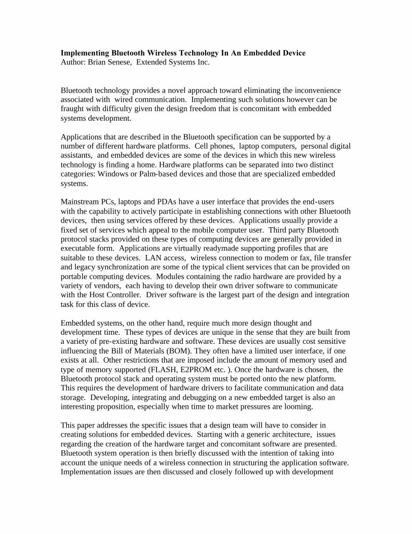
Implementing Bluetooth Wireless Technology In An Embedded Device Author: Brian Senese, Extended Systems Inc. Bluetooth technology provides a novel approach toward eliminating the inconvenience associated with wired communication. Implementing such solutions however can be fraught with difficulty given the design freedom that is concomitant with embedded systems development. Applications that are described in the Bluetooth specification can be supported by a number of different hardware platforms. Cell phones, laptop computers, personal digital assistants, and embedded devices are some of the devices in which this new wireless technology is finding a home. Hardware platforms can be separated into two distinct categories: Windows or Palm-based devices and those that are specialized embedded systems. Mainstream PCs, laptops and PDAs have a user interface that provides the end-users with the capability to actively participate in establishing connections with other Bluetooth devices, then using services offered by these devices. Applications usually provide a fixed set of services which appeal to the mobile computer user. Third party Bluetooth protocol stacks provided on these types of computing devices are generally provided in executable form. Applications are virtually readymade supporting profiles that are suitable to these devices. LAN access, wireless connection to modem or fax, file transfer and legacy synchronization are some of the typical client services that can be provided on portable computing devices. Modules containing the radio hardware are provided by a variety of vendors, each having to develop their own driver software to communicate with the Host Controller. Driver software is the largest part of the design and integration task for this class of device. Embedded systems, on the other hand, require much more design thought and development time. These types of devices are unique in the sense that they are built from a variety of pre-existing hardware and software. These devices are usually cost sensitive influencing the Bill of Materials (BOM). They often have a limited user interface, if one exists at all. Other restrictions that are imposed include the amount of memory used and type of memory supported (FLASH, E2PROM etc. ). Once the hardware is chosen, the Bluetooth protocol stack and operating system must be ported onto the new platform. This requires the development of hardware drivers to facilitate communication and data storage. Developing, integrating and debugging on a new embedded target is also an interesting proposition, especially when time to market pressures are looming. This paper addresses the specific issues that a design team will have to consider in creating solutions for embedded devices. Starting with a generic architecture, issues regarding the creation of the hardware target and concomitant software are presented. Bluetooth system operation is then briefly discussed with the intention of taking into account the unique needs of a wireless connection in structuring the application software. Implementation issues are then discussed and closely followed up with development

ideas that are designed to not only contain the project burn rate but also to get the product to market in as short a time as possible. Embedded Architecture Bluetooth radio hardware has been associated , at least in marketing terms, to a price point of approximately five dollars, making this wireless link very cost effective. To achieve this, hardware solutions consisting of Host and Host Controller will have to be integrated onto a single chip and mass produced. This is unfortunately not the commercial reality of today. Currently, solutions still consist of multiple components. The Host is typically managed on a processor and the Host Controller consists of several integrated circuits. Figure 1 illustrates a familiar architecture that is closely aligned with descriptions as provided in the Bluetooth specification V1.0B. With regard to selecting specific hardware components, one must first consider the application that is to be developed. Processor and memory There are many tradeoffs to be considered when deciding on the hardware architecture. Demanding applications, those that make heavy use of the upper protocol stack (running on the Host) in transferring data, dictate that a 16 bit (or more) processor be used. Memory limitations when using a more powerful processor are relaxed to the point where the only restriction becomes the additional cost of adding memory in the form of Flash or E2PROM. The option of providing non-volatile store required in the management of the Device database is peripheral, yet determines the paradigm that will be used in providing device security. The inclusion of a user interface can increase hardware cost in the BOM, yet allows human intervention for the purposes of configuring the device as well as respond to queries generated as a result of security procedures that may be triggered. Lesser applications can be supported by a smaller 8 bit processor. Processing power is unnecessary in handling sporadic messaging between Bluetooth units. Establishing a connection, service discovery and application setup can easily be handled with less processing power if the resulting utility is nothing more than the establishment of an audio channel. Figure 1 illustrates a current architecture whereby the audio channel (SCO) is supported by the Host Controller hardware and optionally by the Host. Once this channel is requested by the Host application, the need for further Host processing is minimized if not completely eliminated. Disconnecting the audio path requires minimal processing as well.
L2CAP
Link ManagementProtocol
Link Controller
ACL SCO
Baseband Control / Processing
RF Hardware
Audio(optional)
Voice(optional)
RFCOMM SDP
ManagementEntity Security
HCI Transport and hardware driver layers (UART or USB)
Host Controller Interface
Eve
nt M
anag
er
HCI Transport and hardware driver layers (UART or USB)
TCS
OBEX
Blu
etoo
th P
roto
col S
tack
Bluetooth Application CodeO
pera
ting
Sys
tem
Ope
ratin
g S
yste
m In
tegr
atio
n C
ode
Host
Antenna
Figure 1 : An embedded solution consisting of Host and Host Controller
Host Controller
Audio in / out
DevicedBase
Host Controller Interface
Operating System Selection of an operating system (OS) is just as closely related to the application to be supported. Round-robin scheduling is by far the simplest, calling routines in a sequential order, allowing them to run for as long as it takes to process all requests and events, then returning control to the next routine which runs until complete. Figure 2 provides a listing of this very simple routine. Predictability and ease of use are the two benefits associated with this OS. Its suitability for simple applications makes this the OS of choice; especially when its cost in terms of memory use is small and its pecuniary impact
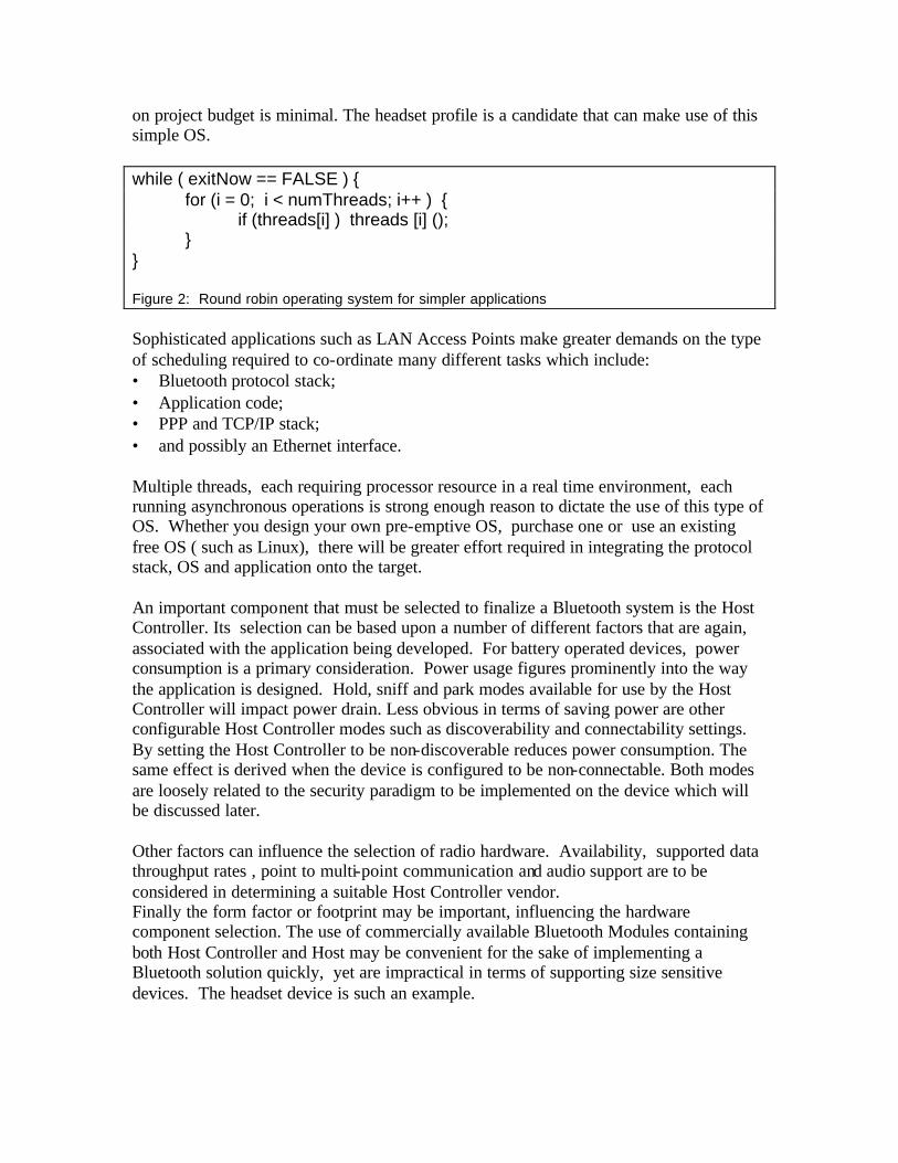
on project budget is minimal. The headset profile is a candidate that can make use of this simple OS. while ( exitNow == FALSE ) { for (i = 0; i < numThreads; i++ ) { if (threads[i] ) threads [i] (); } } Figure 2: Round robin operating system for simpler applications Sophisticated applications such as LAN Access Points make greater demands on the type of scheduling required to co-ordinate many different tasks which include: • Bluetooth protocol stack; • Application code; • PPP and TCP/IP stack; • and possibly an Ethernet interface. Multiple threads, each requiring processor resource in a real time environment, each running asynchronous operations is strong enough reason to dictate the use of this type of OS. Whether you design your own pre-emptive OS, purchase one or use an existing free OS ( such as Linux), there will be greater effort required in integrating the protocol stack, OS and application onto the target. An important component that must be selected to finalize a Bluetooth system is the Host Controller. Its selection can be based upon a number of different factors that are again, associated with the application being developed. For battery operated devices, power consumption is a primary consideration. Power usage figures prominently into the way the application is designed. Hold, sniff and park modes available for use by the Host Controller will impact power drain. Less obvious in terms of saving power are other configurable Host Controller modes such as discoverability and connectability settings. By setting the Host Controller to be non-discoverable reduces power consumption. The same effect is derived when the device is configured to be non-connectable. Both modes are loosely related to the security paradigm to be implemented on the device which will be discussed later. Other factors can influence the selection of radio hardware. Availability, supported data throughput rates , point to multi-point communication and audio support are to be considered in determining a suitable Host Controller vendor. Finally the form factor or footprint may be important, influencing the hardware component selection. The use of commercially available Bluetooth Modules containing both Host Controller and Host may be convenient for the sake of implementing a Bluetooth solution quickly, yet are impractical in terms of supporting size sensitive devices. The headset device is such an example.
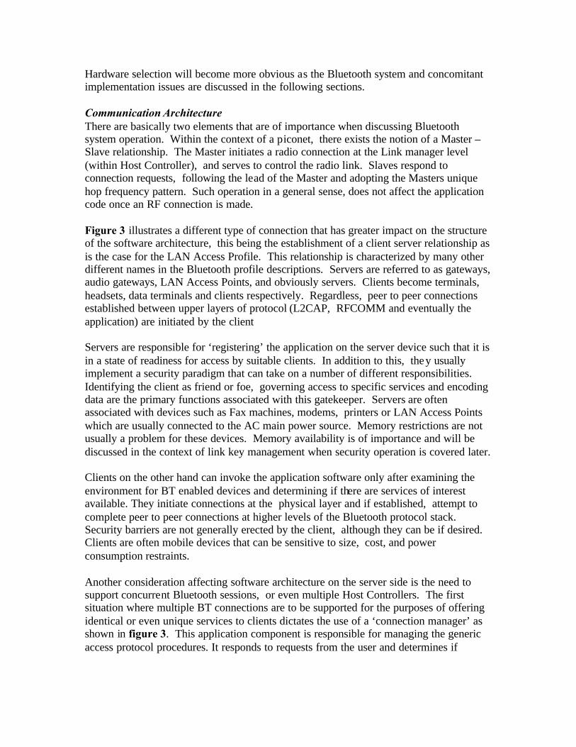
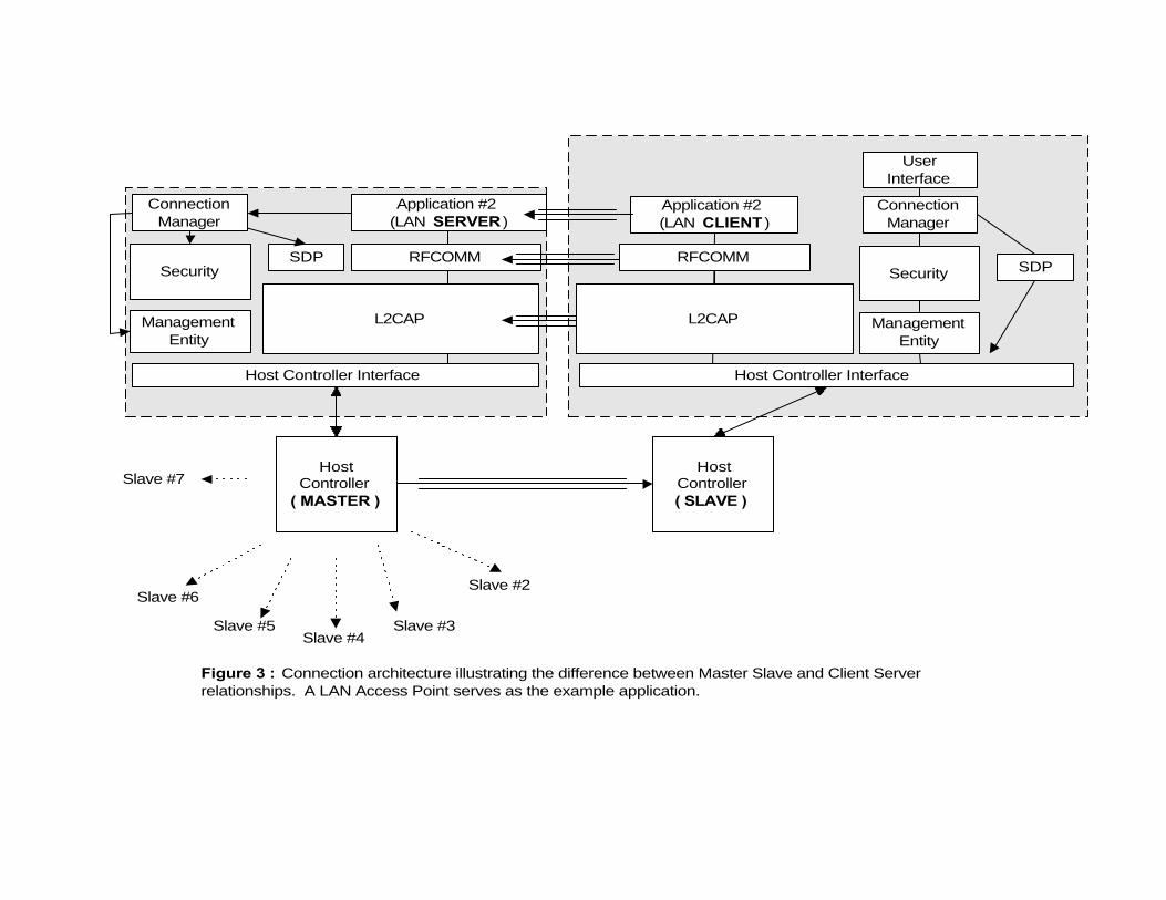
Hardware selection will become more obvious as the Bluetooth system and concomitant implementation issues are discussed in the following sections. Communication Architecture There are basically two elements that are of importance when discussing Bluetooth system operation. Within the context of a piconet, there exists the notion of a Master – Slave relationship. The Master initiates a radio connection at the Link manager level (within Host Controller), and serves to control the radio link. Slaves respond to connection requests, following the lead of the Master and adopting the Masters unique hop frequency pattern. Such operation in a general sense, does not affect the application code once an RF connection is made. Figure 3 illustrates a different type of connection that has greater impact on the structure of the software architecture, this being the establishment of a client server relationship as is the case for the LAN Access Profile. This relationship is characterized by many other different names in the Bluetooth profile descriptions. Servers are referred to as gateways, audio gateways, LAN Access Points, and obviously servers. Clients become terminals, headsets, data terminals and clients respectively. Regardless, peer to peer connections established between upper layers of protocol (L2CAP, RFCOMM and eventually the application) are initiated by the client Servers are responsible for ‘registering’ the application on the server device such that it is in a state of readiness for access by suitable clients. In addition to this, they usually implement a security paradigm that can take on a number of different responsibilities. Identifying the client as friend or foe, governing access to specific services and encoding data are the primary functions associated with this gatekeeper. Servers are often associated with devices such as Fax machines, modems, printers or LAN Access Points which are usually connected to the AC main power source. Memory restrictions are not usually a problem for these devices. Memory availability is of importance and will be discussed in the context of link key management when security operation is covered later. Clients on the other hand can invoke the application software only after examining the environment for BT enabled devices and determining if there are services of interest available. They initiate connections at the physical layer and if established, attempt to complete peer to peer connections at higher levels of the Bluetooth protocol stack. Security barriers are not generally erected by the client, although they can be if desired. Clients are often mobile devices that can be sensitive to size, cost, and power consumption restraints. Another consideration affecting software architecture on the server side is the need to support concurrent Bluetooth sessions, or even multiple Host Controllers. The first situation where multiple BT connections are to be supported for the purposes of offering identical or even unique services to clients dictates the use of a ‘connection manager’ as shown in figure 3. This application component is responsible for managing the generic access protocol procedures. It responds to requests from the user and determines if
SDP
ManagementEntity
Security
Figure 3 : Connection architecture illustrating the difference between Master Slave and Client Serverrelationships. A LAN Access Point serves as the example application.
Application #2(LAN SERVER )
HostController
( MASTER )
Application #2(LAN CLIENT )
HostController( SLAVE )
RFCOMM
Host Controller Interface
L2CAP
Slave #2
Slave #3Slave #4
Slave #5
Slave #6
Slave #7
ConnectionManager
ManagementEntity
UserInterface
Security
ConnectionManager
SDPRFCOMM
L2CAP
Host Controller Interface

Bluetooth services are in range. It then establishes a connection if a suitable service is found. Figure 4 illustrates a screen shot of a connection manager running on a PC. It rovides Inquiry, Connect and security services to the client device; note the SDP function is not included in this version of the manager. Once a connection is established, services can be accessed. Figure 5 shows a screen shot of a service offered on the server; this is an Object Push application that can run over the radio link created as a result of the ‘connection manager’.
The use of multiple host controllers is a possibility, enabling the server to extend beyond the 7 active master – slave connection limit. Multiple Host controllers equate to having multiple piconets working in the same area; interference between piconets has been reported to be noticeable when 4 or more piconets are working simultaneously in supporting data connections. As far as software architecture is concerned, managing multiple Host controllers requires that the protocol stack be able to store important context information (radio state) for each independent host controller. Complexity of the software architecture increases in this situation. One solution for this situation is to create multiple instances of the BT protocol stack running on the Host, each instance managing Host controller context information. Application access to the top of each stack instance must then be carefully managed, impacting the simplistic design of the connection manager. Software architecture is also strongly influenced by the inclusion of a user interface, the inclusion of non-volatile store (NVS) and whether the Host is to support an audio channel. The most obvious form of a user interface is the inclusion of a keypad and display onto the Bluetooth device itself. Other less intrusive forms of a user interface include the use of internal server application capable of communicating with external client devices. Clients could get information from or place information into the
Bluetooth device either in the form of a file, via Object Exchange (OBEX) or perhaps through a web browser session as illustrated in figure 6. A remote user interface reduces cost of the server unit and provides the capability to configure the server device dynamically as well as extract important operational information (such as LAN traffic
loading) from the server. For instance, a print server could furnish potential users with user fee information and accept a credit card if the user wanted to purchase print services. This interaction could be supported via a web server application on the Bluetooth server and a browser on the client. In terms of configuring a device, PIN information, security model settings are two primary candidates that could be dynamically configured from a remote device. Keep in mind that this device does not have to be Bluetooth enabled. LAN access points for example are usually hardwired to networks which potentially can provide network
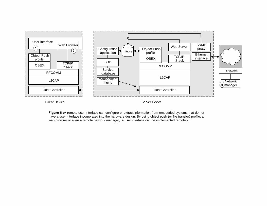
Figure 6 : A remote user interface can configure or extract information from embedded systems that do nothave a user interface incorporated into the hardware design. By using object push (or file transfer) profile, aweb browser or even a remote network manager, a user interface can be implemented remotely.
L2CAP
RFCOMM
TCP/IPStackOBEX
Object Pushprofile
L2CAP
RFCOMM
Web Server
TCP/IPStackOBEX
Object Pushprofile
Client Device Server Device
Store
Host Controller Host Controller
Web BrowserUser interface
Configurationapplication
ManagementEntity
SDP
Servicedatabase
SNMPproxy
Ethernetinterface
Network
12
Networkmanager3
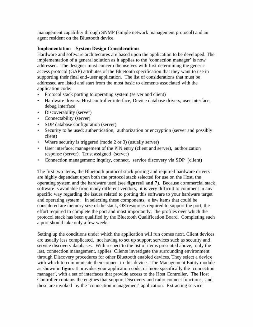
management capability through SNMP (simple network management protocol) and an agent resident on the Bluetooth device. Implementation – System Design Considerations Hardware and software architectures are based upon the application to be developed. The implementation of a general solution as it applies to the ‘connection manager’ is now addressed. The designer must concern themselves with first determining the generic access protocol (GAP) attributes of the Bluetooth specification that they want to use in supporting their final end-user application. The list of considerations that must be addressed are listed and start from the most basic to elements associated with the application code: • Protocol stack porting to operating system (server and client) • Hardware drivers: Host controller interface, Device database drivers, user interface,
debug interface • Discoverability (server) • Connectability (server) • SDP database configuration (server) • Security to be used: authentication, authorization or encryption (server and possibly
client) • Where security is triggered (mode 2 or 3) (usually server) • User interface: management of the PIN entry (client and server), authorization
response (server), Trust assigned (server) • Connection management: inquiry, connect, service discovery via SDP (client) The first two items, the Bluetooth protocol stack porting and required hardware drivers are highly dependant upon both the protocol stack selected for use on the Host, the operating system and the hardware used (see figures1 and 7). Because commercial stack software is available from many different vendors, it is very difficult to comment in any specific way regarding the issues related to porting this software to your hardware target and operating system. In selecting these components, a few items that could be considered are memory size of the stack, OS resources required to support the port, the effort required to complete the port and most importantly, the profiles over which the protocol stack has been qualified by the Bluetooth Qualification Board. Completing such a port should take only a few weeks. Setting up the conditions under which the application will run comes next. Client devices are usually less complicated, not having to set up support services such as security and service discovery databases. With respect to the list of items presented above, only the last, connection management, applies. Clients investigate the surrounding environment through Discovery procedures for other Bluetooth enabled devices. They select a device with which to communicate then connect to this device. The Management Entity module as shown in figure 1 provides your application code, or more specifically the ‘connection manager’, with a set of interfaces that provide access to the Host Controller. The Host Controller contains the engines that support Discovery and radio connect functions, and these are invoked by the ‘connection management’ application. Extracting service
Service Security
Authorization required ? yesAuthentication required ? yes
Encryption required ? no
RFCOMMchannel 1
L2CAPPSM 5
Service Database
Service Device Information
BD_ADDR 123456
Device Database
Trust level TrustedLink key 1232342324234Authorization required ? no
Authentication required ? yes
Encryption required ? yes
RFCOMMchannel 1
SecurityManager
RFCOMM
Non-volatile memory
L2CAP
HCI
Application(configuredatabase)
Application(PIN entry)
Application(Authorization
entry)
CodeDevelopment
Figure 7: Components supporting Bluetooth Security and areas that require software design insupport of security implemetation. Handlers to retreive the PIN and authorization response as wellas Device database hardware drivers.
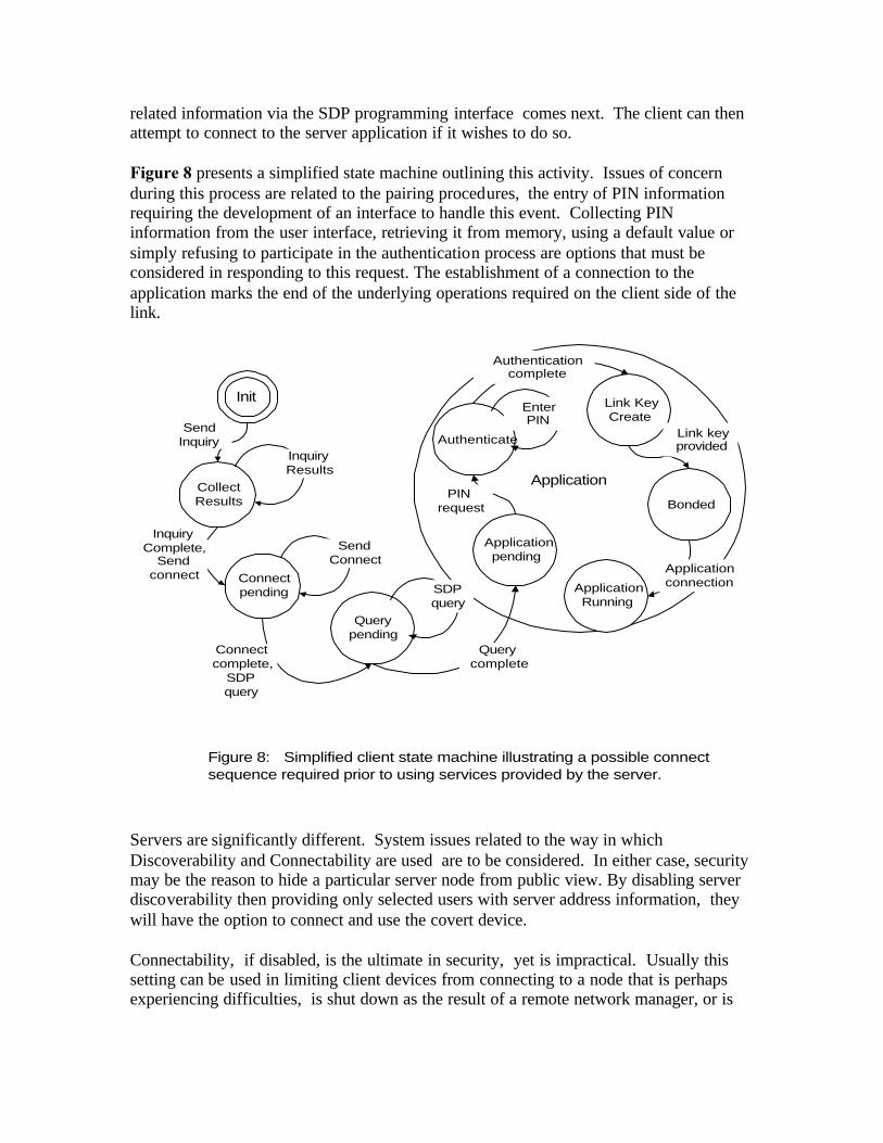
related information via the SDP programming interface comes next. The client can then attempt to connect to the server application if it wishes to do so. Figure 8 presents a simplified state machine outlining this activity. Issues of concern during this process are related to the pairing procedures, the entry of PIN information requiring the development of an interface to handle this event. Collecting PIN information from the user interface, retrieving it from memory, using a default value or simply refusing to participate in the authentication process are options that must be considered in responding to this request. The establishment of a connection to the application marks the end of the underlying operations required on the client side of the link.
CollectResults
Init
Connectpending
Applicationpending
Authenticate
Link KeyCreate
Bonded
ApplicationRunning
Application
SendInquiry
Querypending
InquiryResults
InquiryComplete,
Sendconnect
SendConnect
Connectcomplete,
SDPquery
Querycomplete
SDPquery
PINrequest
Authenticationcomplete
EnterPIN
Link keyprovided
Applicationconnection
Figure 8: Simplified client state machine illustrating a possible connectsequence required prior to using services provided by the server.
Servers are significantly different. System issues related to the way in which Discoverability and Connectability are used are to be considered. In either case, security may be the reason to hide a particular server node from public view. By disabling server discoverability then providing only selected users with server address information, they will have the option to connect and use the covert device. Connectability, if disabled, is the ultimate in security, yet is impractical. Usually this setting can be used in limiting client devices from connecting to a node that is perhaps experiencing difficulties, is shut down as the result of a remote network manager, or is
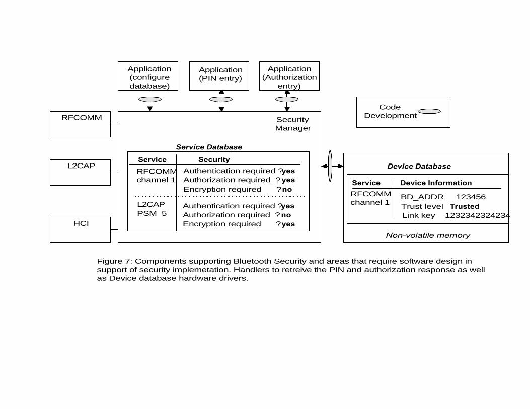
experiencing high traffic usage ( preventing access to new users which could degrade service to existing users). Configuring the Service Discovery database is required on the server side as well (remaining unused on the client side of the link). Contained within this database is critical information related to the protocol connections to be used. For example, the RFCOMM channel number through which services are provided must be specified. SDP configuration is completed prior to the server going ‘online’ and its content being modified dynamically. Security measures to be used in preventing unauthorized access to the server are an important consideration as well. Deciding on the level of security to implement is dependant upon three things: • the application; • guidance offered in the Bluetooth specification; • and the designer discretion. Mode 2 security is triggered at either the L2CAP or RFCOMM protocol layers and is designed to protect the server node from rogue users as well as protect specific services offered. There are three components forming a security troika; authentication, authorization and encryption. Authentication is used in verifying the identity of the client through the entry of an identical PIN on client and server nodes. Authorization protects a specific service by asking (via a user interface) if the remote device is to be granted access; or more true to Bluetooth terminology, if the device is to be Trusted. Configuration of the Service database, an entity managed by the Security manager module, determines: • if mode 2 security is to be triggered; • where security measures are to be triggered; • the types of security that are to be used. Figure 7 illustrates two data structures used in managing security. The service database contains records that link the service being protected to the security measures required. The device database persistently stores remnants that are created during the execution of security. By associating a created link key (as generated within the Host Controller resulting from the successful completion of authentication) with a particular remote device, authentication can proceed without the need for pairing (PIN entry). If designated as a Trusted device, authorization will complete without user interaction. The size of this non-volatile data storage area is dependent upon the amount of information that needs to be kept on a semi-permanent basis. Database record entries are typically erased after the passage of a preset period of time to maintain some level of security and protecting the server from potential new owners of a previously Trusted client device. Periodically invoking authorization between Bluetooth devices is a prudent security precaution. Embedded devices not having the luxury of a user interface can overcome this limitation by handling authentication and authorization in an automated fashion. Predetermined
PIN data can be stored to memory for retrieval at a later time, or the default value can be used (zero length value) to proceed through authentication. Devices that are discovered to be within range can automatically be designated as Trusted; bypassing the need for a UI. The creation and sharing of link key data during the bonding process may be influenced by the size of the Device database as well. Combo keys for every unique connection between Bluetooth units may be curtailed by limited NVS memory. Also, the way in which such keys are distributed could be limited in that the device with limited NVS could always provide its Unit key for use as the link key, keeping its NVS memory requirements low. Mode 3 security, if selected by the systems designer, prevents a connection at the link Manager level from being established before authentication is successfully completed; authorization is not supported by this security mode. Configuration is necessary to trigger this mode, and is done by configuring the Host Controller directly through the HCI interface. Application programming interfaces may be provided through the Security manager to establish mode 3 security; this element of programming is dependant upon the protocol stack vendors implementation. Implementation Considerations Security, when invoked, is now briefly described for the purposes of illustrating the involvement that the application has in its execution. Many of the procedures are executed transparently to the application. Figure 9 provides a global view of the authentication process. Application software initiates a peer to peer connection between L2CAP layers, triggering the security manager as shown in this case. (RFCOMM could have been selected as the trigger point instead.) The security manager searches the Service database for records that are applicable to the service being accessed, if security is required, it is started. In this case, authentication is requested by the security manager and the Host Controller responds to this request asking for a link key. The Security manager looks in the Device database for this entry; it does not exist in this example. The security manager then invokes application code, asking for both a PIN and if the resulting link key generated (if authentication passes) is to be stored in NVS. A PIN is provided through a user interface, retrieved from memory or the default PIN value is tried; the application can also respond negatively without a PIN causing failure of authentication.
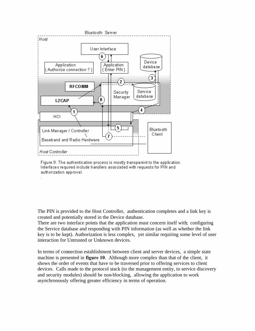
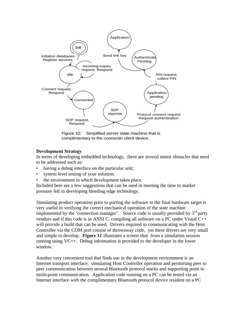
The PIN is provided to the Host Controller, authentication completes and a link key is created and potentially stored in the Device database. There are two interface points that the application must concern itself with; configuring the Service database and responding with PIN information (as well as whether the link key is to be kept). Authorization is less complex, yet similar requiring some level of user interaction for Untrusted or Unknown devices. In terms of connection establishment between client and server devices, a simple state machine is presented in figure 10. Although more complex than that of the client, it shows the order of events that have to be traversed prior to offering services to client devices. Calls made to the protocol stack (to the management entity, to service discovery and security modules) should be non-blocking, allowing the application to work asynchronously offering greater efficiency in terms of operation.
Idle
Init
Connected
Applicationpending
AuthenticatePending
Initialize databasesRegister services
SDPreponse
Incoming inquiryrequest, Respond
Connect request,Respond
SDP request,Respond
Protocol connect requestRequest authentication
PIN request,collect PIN
Figure 10: Simplified server state machine that iscomplimentary to the connectin client device.
Application
Send link key
Development Strategy In terms of developing embedded technology, there are several minor obstacles that need to be addressed such as: • having a debug interface on the particular unit; • system level testing of your solution; • the environment in which development takes place. Included here are a few suggestions that can be used in meeting the time to market pressure felt in developing bleeding edge technology. Simulating product operation prior to porting the software to the final hardware target is very useful in verifying the correct mechanical operation of the state machine implemented by the ‘connection manager’. Source code is usually provided by 3rd party vendors and if this code is in ANSI C, compiling all software on a PC under Visual C++ will provide a build that can be used. Drivers required in communicating with the Host Controller via the COM port consist of throwaway code, yet these drivers are very small and simple to develop. Figure 11 illustrates a screen shot from a simulation session running using VC++. Debug information is provided to the developer in the lower window. Another very convenient tool that finds use in the development environment is an Internet transport interface, simulating Host Controller operation and permitting peer to peer communication between several Bluetooth protocol stacks and supporting point to multi-point communication. Application code running on a PC can be tested via an Internet interface with the complimentary Bluetooth protocol device resident on a PC

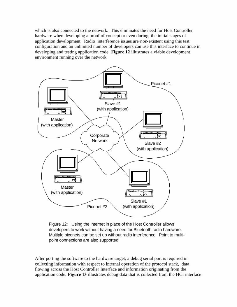
which is also connected to the network. This eliminates the need for Host Controller hardware when developing a proof of concept or even during the initial stages of application development. Radio interference issues are non-existent using this test configuration and an unlimited number of developers can use this interface to continue in developing and testing application code. Figure 12 illustrates a viable development environment running over the network.
Figure 12: Using the internet in place of the Host Controller allowsdevelopers to work without having a need for Bluetooth radio hardware.Multiple piconets can be set up without radio interference. Point to multi-point connections are also supported
Master(with application)
Slave #1(with application)
CorporateNetwork Slave #2
(with application)
Master(with application)
Piconet #1
Slave #1(with application)Piconet #2
After porting the software to the hardware target, a debug serial port is required in collecting information with respect to internal operation of the protocol stack, data flowing across the Host Controller Interface and information originating from the application code. Figure 13 illustrates debug data that is collected from the HCI interface

aiding the developer in isolating defective operation. When running in debug mode on the target hardware, keep in mind that the software image is most likely going to be larger than the build that will eventually go into production (with all debug tools removed from the software load). Therefore, the prototype target hardware should be able to support larger amounts of memory to account for code bloat when debug capability is enabled. The final target hardware can have less memory, reducing BOM cost and footprint.
Wrap up Embedded devices are unique in that every development team has the freedom to choose components that are to make up the hardware solution. The product definition originating from the marketing unit coupled with the creative component of the design team are variables that flavor the design architecture as well, providing the unique differentiated product offering to the market. This paper has outlined considerations that need to be made in creating an embedded Bluetooth solution including both hardware and software components. It was the intention that not only was this to provide some basic

guidelines based upon Bluetooth system operation, but also provoked thought with regard to possible designs being considered by the reader. Bio Brian Senese holds an M.E.Sc. from the University of Western Ontario and has been involved in the development of wireless communications systems for 15 years. Nortel, ADC Telecommunications, Lucent and Uniden are only a few of the companies that he has worked for. Currently, he is a systems engineer for Extended Systems Inc.