1) The uveitis is profiled Uveitis 2) The profiled case is ...
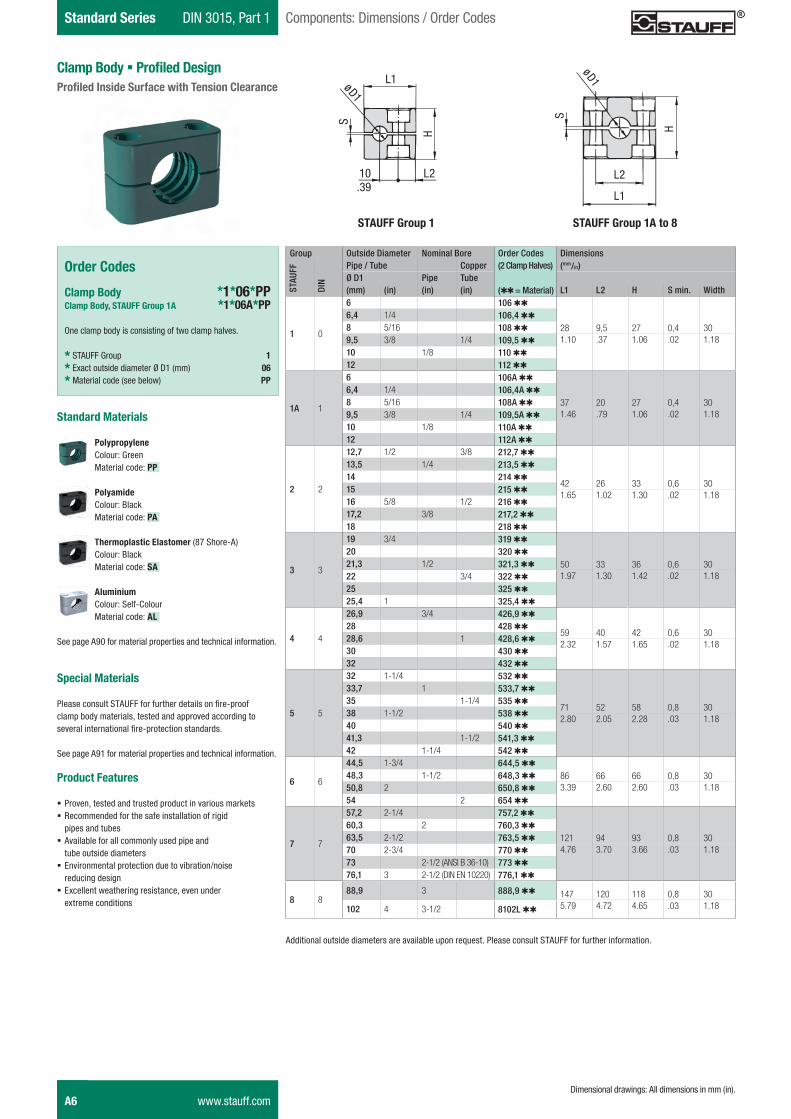
Standard Series DIN 3015, Part 1 Components: Dimensions / Order Codes
Clamp Body � Profiled DesignProfiled Inside Surface with Tension Clearance
Group Outside Diameter Nominal Bore Order Codes Dimensions
STAU
FF
DIN
Pipe / Tube Copper (2 Clamp Halves) (mm/in)Ø D1 Pipe Tube(mm) (in) (in) (in) (QQ = Material) L1 L2 H S min. Width
1 0
6 106 QQ
28 9,5 27 0,4 306,4 1/4 106,4 QQ
8 5/16 108 QQ
9,5 3/8 1/4 109,5 QQ 1.10 .37 1.06 .02 1.1810 1/8 110 QQ
12 112 QQ
1A 1
6 106A QQ
37 20 27 0,4 306,4 1/4 106,4A QQ
8 5/16 108A QQ
9,5 3/8 1/4 109,5A QQ 1.46 .79 1.06 .02 1.1810 1/8 110A QQ
12 112A QQ
2 2
12,7 1/2 3/8 212,7 QQ
42 26 33 0,6 30
13,5 1/4 213,5 QQ
14 214 QQ
15 215 QQ1.65 1.02 1.30 .02 1.18
16 5/8 1/2 216 QQ
17,2 3/8 217,2 QQ
18 218 QQ
3 3
19 3/4 319 QQ
50 33 36 0,6 3020 320 QQ
21,3 1/2 321,3 QQ
22 3/4 322 QQ 1.97 1.30 1.42 .02 1.1825 325 QQ
25,4 1 325,4 QQ
4 4
26,9 3/4 426,9 QQ
59 40 42 0,6 3028 428 QQ
28,6 1 428,6 QQ2.32 1.57 1.65 .02 1.18
30 430 QQ
32 432 QQ
5 5
32 1-1/4 532 QQ
71 52 58 0,8 30
33,7 1 533,7 QQ
35 1-1/4 535 QQ
38 1-1/2 538 QQ2.80 2.05 2.28 .03 1.18
40 540 QQ
41,3 1-1/2 541,3 QQ
42 1-1/4 542 QQ
6 6
44,5 1-3/4 644,5 QQ
86 66 66 0,8 3048,3 1-1/2 648,3 QQ
50,8 2 650,8 QQ 3.39 2.60 2.60 .03 1.1854 2 654 QQ
7 7
57,2 2-1/4 757,2 QQ
121 94 93 0,8 3060,3 2 760,3 QQ
63,5 2-1/2 763,5 QQ
70 2-3/4 770 QQ 4.76 3.70 3.66 .03 1.1873 2-1/2 (ANSI B 36-10) 773 QQ
76,1 3 2-1/2 (DIN EN 10220) 776,1 QQ
8 888,9 3 888,9 QQ 147 120 118 0,8 30
102 4 3-1/2 8102L QQ 5.79 4.72 4.65 .03 1.18
Standard Materials
Polypropylene Colour: Green Material code: PP
Polyamide Colour: Black Material code: PA
Thermoplastic Elastomer (87 Shore-A) Colour: Black Material code: SA
Aluminium Colour: Self-Colour Material code: AL
See page A90 for material properties and technical information.
Special Materials
Please consult STAUFF for further details on fire-proof clamp body materials, tested and approved according to several international fire-protection standards.
See page A91 for material properties and technical information.
Product Features
� Proven, tested and trusted product in various markets � Recommended for the safe installation of rigid pipes and tubes
� Available for all commonly used pipe and tube outside diameters
� Environmental protection due to vibration/noise reducing design
� Excellent weathering resistance, even under extreme conditions
Order Codes
Clamp Body *1*06*PPClamp Body, STAUFF Group 1A *1*06A*PP
One clamp body is consisting of two clamp halves.
* STAUFF Group 1
* Exact outside diameter Ø D1 (mm) 06
* Material code (see below) PP
Additional outside diameters are available upon request. Please consult STAUFF for further information.
L1
H
10 L 2
ø D 1
S
L 2
ø D 1L 1
S
H
STAUFF Group 1 STAUFF Group 1A to 8
.39
A6 www.stauff.comDimensional drawings: All dimensions in mm (in).
Schelle-2012-03-28-EN.indd 6 29.03.2012 10:10:31
STAU
FF
Clam
psA
DIN 3015, Part 1 Standard SeriesComponents: Dimensions / Order Codes
Order Codes
Clamp Body *1*06*PPHClamp Body, STAUFF Group 1A *1*06A*PPH
One clamp body is consisting of two clamp halves.
* STAUFF Group 1
* Exact outside diameter Ø D1 (mm) 06
* Material code (see below) PPH
Clamp Body � Type HSmooth Inside Surface without Tension Clearance
Standard Materials
Polypropylene Colour: Green Material code: PPH
Polyamide Colour: Black Material code: PAH
Thermoplastic Elastomer (87 Shore-A) Colour: Black Material code: SAH
See page A90 for material properties and technical information.
Special Materials
Please consult STAUFF for further details on fire-proof clamp body materials, tested and approved according to several international fire-protection standards.
See page A91 for material properties and technical information.
Product Features
� Proven, tested and trusted product in various markets � Recommended for the safe installation of hoses and cables � Chamfered edges avoid damaging of the hoses and cables � Available for all commonly used hose and cable outside diameters
� Excellent weathering resistance, even under extreme conditions
Additional outside diameters are available upon request. Please consult STAUFF for further information.
Group Outside Diameter Nominal Bore Order Codes Dimensions
STAU
FF
DIN
Hose Hydraulic Hose (2 Clamp Halves) (mm/in)Ø D1 SAE 100 R1 AT(mm) (in) (in) (QQQ = Material) L1 L2 H Width
1 0
6 106 QQQ
28 9,5 26 306,4 1/4 106,4 QQQ
8 5/16 108 QQQ
9,5 3/8 109,5 QQQ 1.10 .37 1.02 1.1810 110 QQQ
12 112 QQQ
1A 1
6 106A QQQ
37 20 26 306,4 1/4 106,4A QQQ
8 5/16 108A QQQ
9,5 3/8 109,5A QQQ 1.46 .79 1.02 1.1810 110A QQQ
12 112A QQQ
2 2
12,7 1/2 212,7 QQQ
42 26 32 30
13,5 213,5 QQQ
14 214 QQQ
15 215 QQQ1.65 1.02 1.26 1.18
16 5/8 216 QQQ
17,2 217,2 QQQ
18 218 QQQ
3 3
13,4 1/4 313,4 QQQ
50 33 35,5 30
17,4 3/8 317,4 QQQ
19 3/4 319 QQQ
20 320 QQQ
20,5 1/2 320,5 QQQ
21,3 321,3 QQQ 1.97 1.30 1.40 1.1822 322 QQQ
23,9 5/8 323,9 QQQ
25 325 QQQ
25,4 1 325,4 QQQ
4 4
26,9 426,9 QQQ
59 40 41,5 3028 428 QQQ
30 430 QQQ 2.32 1.57 1.63 1.1832 432 QQQ
5 5
27,8 3/4 527,8 QQQ
71 52 56,5 30
32 1-1/4 532 QQQ
33,7 533,7 QQQ
35 535 QQQ
35,7 1 535,7 QQQ2.80 2.05 2.22 1.18
38 1-1/2 538 QQQ
40 540 QQQ
42 542 QQQ
43,8 1-1/4 543,8 QQQ
6 6
44,5 1-3/4 644,5 QQQ
86 66 64,5 3048,3 648,3 QQQ
49,8 1-1/2 649,8 QQQ3.39 2.60 2.54 1.18
50,8 2 650,8 QQQ
54 654 QQQ
7 7
57,2 2-1/4 757,2 QQQ
121 94 92 3060,3 760,3 QQQ
63,5 2-1/2 763,5 QQQ
70 2-3/4 770 QQQ 4.76 3.70 3.62 1.1873 773 QQQ
76,1 3 776,1 QQQ
8 888,9 888,9 QQQ 147 1 116 30
102 4 8102L QQQ 5.79 4.72 4.57 1.18
STAUFF Group 1 STAUFF Group 1A to 8
L1
H
10 L 2
øD1
L2
øD
1
L1
H
www.stauff.com A7
.39
Dimensional drawings: All dimensions in mm (in).
Schelle-2012-03-28-EN.indd 7 29.03.2012 10:10:32
Standard Series DIN 3015, Part 1 Components: Dimensions / Order Codes
Clamp Body with Rubber InsertType RI
Order Codes
Clamp Assembly *4*06*PPR
One assembly is consisting of one clamp body and one insert.
* STAUFF Group 4
* Exact outside diameter Ø D (mm) 06
* Material code (see below) PPR
Clamp Body *4*PPR
One clamp body is consisting of two clamp halves.
* STAUFF Group 4
* Material code (see below) PPR
Rubber Insert *RI*06*(4+4S)
* Rubber Insert RI
* Exact outside diameter Ø D (mm) 06
* STAUFF Group 4 (Standard) and 4S (Heavy) (4+4S) 6 (Standard) and 5S (Heavy) (6+5S)
Group Outside Diameter Order Codes (QQR = Clamp Body Material) Dimensions
STAU
FF
DIN
Pipe / Tube / Hose Clamp Assembly Clamp Body Rubber Insert * (mm/in)Ø D (Clamp Body +(mm) (in) Rubber Insert) (2 Clamp Halves) Ø D1 L1 L2 H Width
4 4
6 406 QQR
4 QQR
RI 06 (4+4S)
25 59 40 41,2 30
8 5/16 408 QQR RI 08 (4+4S)
10 410 QQR RI 10 (4+4S)
12 412 QQR RI 12 (4+4S)
12,7 1/2 412,7 QQR RI 12,7 (4+4S)
14 414 QQR RI 14 (4+4S).98 2.32 1.57 1.62 1.18
15 415 QQR RI 15 (4+4S)
16 5/8 416 QQR RI 16 (4+4S)
17,2 417,2 QQR RI 17,2 (4+4S)
18 418 QQR RI 18 (4+4S)
19 3/4 419 QQR RI 19 (4+4S)
6 6
20 620 QQR
6 QQR
RI 20 (6+5S)
38 86 66 64,5 30
21,3 621,3 QQR RI 21,3 (6+5S)
22 7/8 622 QQR RI 22 (6+5S)
25 625 QQR RI 25 (6+5S)
26,9 626,9 QQR RI 26,9 (6+5S) 1.50 3.39 2.60 2.54 1.18
28 628 QQR RI 28 (6+5S)
30 630 QQR RI 30 (6+5S)
32 1-1/4 632 QQR RI 32 (6+5S)
* Rubber Inserts for Standard Series clamp bodies, STAUFF Group 4 also fit into Heavy Series clamp bodies, STAUFF Group 4S. Rubber Inserts for Standard Series clamp bodies, STAUFF Group 6 also fit into Heavy Series clamp bodies, STAUFF Group 5S.
Additional outside diameters are available upon request. Please consult STAUFF for further information.
Standard Materials
Polypropylene Colour: Black Material code: PPR
Polyamide Colour: Black Material code: PAR
Rubber Insert Thermoplastic Elastomer (73 Shore-A) Colour: Black
See page A90 for material properties and technical information.
Special Materials
Please consult STAUFF for further details on fire-proof clamp body materials, tested and approved according to several international fire-protection standards.
See page A91 for material properties and technical information.
Product Features
� Proven, tested and trusted product in various markets � Either for the extra vibration/noise reducing installation of pipes and tubes or the extra gentle installation of hoses and cables
� Available for all commonly used outside diameters � Excellent weathering resistance, even under extreme conditions
L2
L1
H
øDøD1
Clamp BodyRubber Insert with Film Hinge
A8 www.stauff.com
Schelle-2012-03-28-EN.indd 8 29.03.2012 10:10:33
STAU
FF
Clam
psA
DIN 3015, Part 1 Standard SeriesComponents: Dimensions / Order Codes
Clamp Body � Compact DesignType CC
Product Features
� Only one clamp body required for two different hose diameters (compact hose + regular hose)
� Rotate upper clamp half by 180° and use clamp body to fasten compact hoses instead of regular hoses
� Available for three different combinations of outside hose diamaters
� Outer dimensions according to DIN 3015, Part 1 � Effective cost reduction due to lower inventories
Group Outside Diameter Outside Diameter Order Codes Dimensions (mm/in)
STAU
FF
DIN
Regular Hose Compact Hose (2 Clamp Halves)Ø D1 Ø D2 H(mm) (in) (mm) (in) (QQQ = Material) L1 L2 Regular Hose Compact Hose B
3 3
19 .75 17,4 .69 319 QQQ-CC
50 33 35,5 34 3022,2 .87 20,6 .81 322,2 QQQ-CC
1.97 1.30 1.40 1.34 1.18
25,4 1.00 23,7 .93 325,4 QQQ-CC
Additional outside diameters are available upon request. Please consult STAUFF for further information.
Order Codes
Clamp Body *3*19*PPH-CC
One clamp body is consisting of two clamp halves.
* STAUFF Group 3
* Outside diameter Ø D1 (mm) of regular hose 19
* Material code (see below) PPH-CC
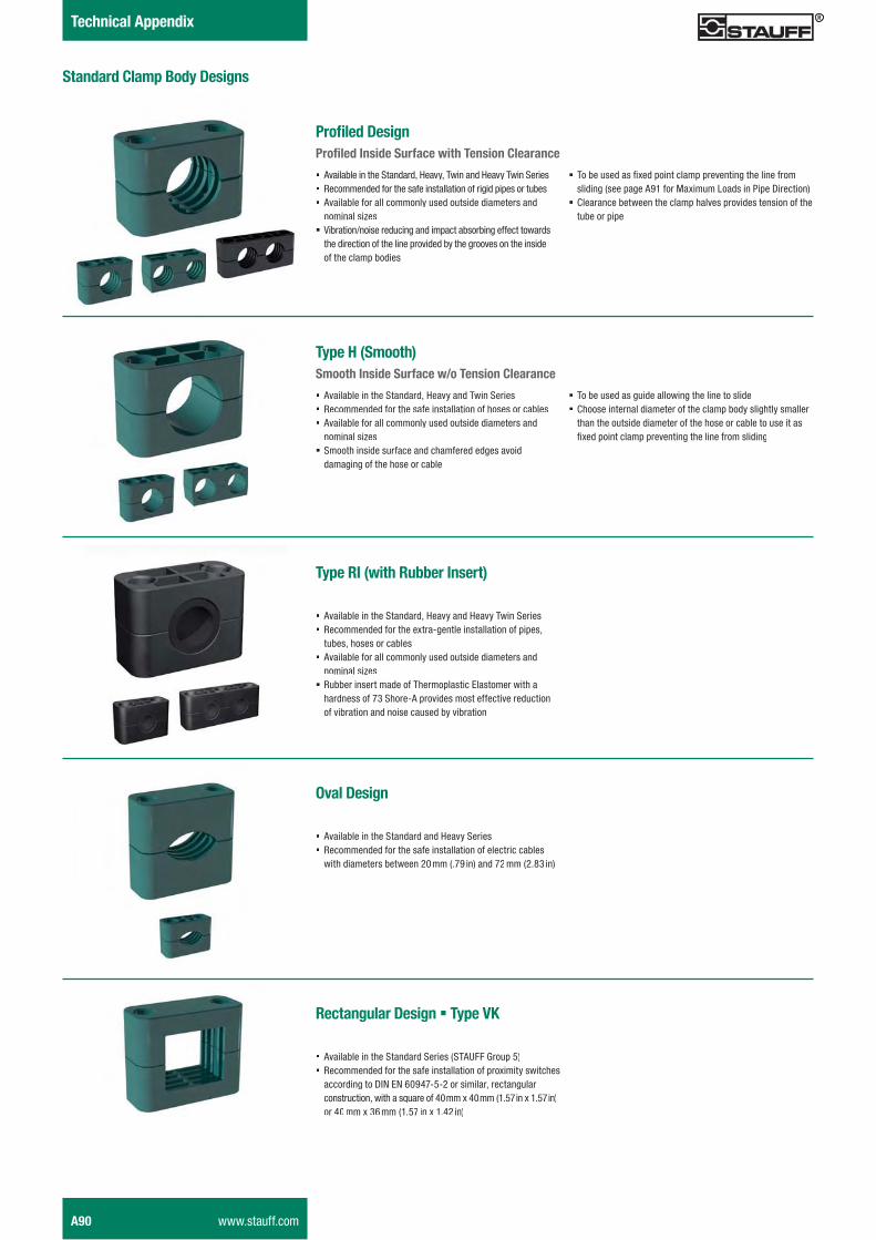
Clamp Body � Oval Design
Special Materials
Please consult STAUFF for further details on fire-proof clamp body materials, tested and approved according to several international fire-protection standards.
See page A91 for material properties and technical information.
Clamp Body � Rectangular DesignType VK
Product Features
� Outer dimensions of clamp body according to Standard Series, STAUFF Group 5 � For proximity switches according to DIN EN 60947-5-2 or similar, rectangular construction, with a square of 40 mm x 40 mm / 1.57 in x 1.57 in or 40 mm x 36 mm / 1.57 in x 1.42 in
� For proximity switches according to DIN EN 60947-5-2 or similar, round construction, please use Standard Series clamp body, STAUFF Group 4, with the diameter required (e.g. 430 PP)
� Use with Hexagon Rail Nut SM and Mounting Rail TS to provide axial and horizontal position adjustment when loosening the bolts
Product Features
� Outer dimensions of clamp body according to Standard Series, STAUFF Group 6 � For electric cables with diameters between 20 mm / .79 in and 50 mm / 1.97 in � For electric cables with diameters between 40 mm / 1.57 in and 72 mm / 2.83 in, please use Heavy Series clamp body, types 6040-72 PP and 6040-72 PA
� Recommended to use with Hexagon Head Bolts AS and Cover Plate DP, Socket Cap Screw IS (with washer) or Slotted Head Screw LI (with washer)
� For varying cable diameters, only the bolt lengths need to be varied
Order Codes
One clamp body is consisting of two clamp halves.
Clamp Body 540-40 PP-VKRectangular design with a rectangular of 40 mm x 40 mm / 1.57 in x 1.57 in
Clamp Body 540-36 PP-VKRectangular design with a rectangular of 40 mm x 36 mm / 1.57 in x 1.42 in
Please replace PP by PA to order a clamp body made of Polyamide instead of Polypropylene.
Order Codes
One clamp body is consisting of two clamp halves.
Clamp Body 620-50 PPOval design with a diameter between 20 mm / .79 in and 50 mm / 1.97 in
Please replace PP by PA to order a clamp body made of Polyamide instead of Polypropylene.
Standard Materials
Polypropylene Colour: Black Material code: PPH-CC
Polyamide Colour: Black Material code: PAH-CC
See page A90 for material properties and technical information.
For Use with Regular HoseFor Use with Compact Hose
(Upper Clamp Half rotated by 180°)
H
L2
L1B
Ø D1 H
L2
L1B
Ø D2
www.stauff.com A9
Schelle-2012-03-28-EN.indd 9 29.03.2012 10:10:35
Standard Series DIN 3015, Part 1 Components: Dimensions / Order Codes
A10 www.stauff.com
Order Codes
Clamp Body *2*12,7*ACTClamp Body, STAUFF Group 1A *1*06,4A*ACT
One clamp body consists of two clamp halves, each with two integrated rubber strips.
* STAUFF Group 2
* Exact outside diameter Ø D1 (mm) 12,7
* Material code (see below) ACT
Additional outside diameters are available upon request. Please consult STAUFF for further information.
Clamp Body � Type ACTAnti Corrosion Technology
W
ØD2
ØD1
L2
L1
H
Integrated Rubber Strips made of Anti-Corrosion Elastomer
Group Outside Diameter Order Codes Dimensions (mm/in)
STAU
FF
DIN
Pipe (2 Clamp Halves)Ø D1(mm) (in) ØD2 W L1 L2 H Width
1A 1
6 106A ACT9 1,4
37 20 26 30
.35 .06
6,4 1/4 106,4A ACT9,4 1,5.37 .06
9,5 3/8 109,5A ACT12,5 2,2.49 .09 1.46 .79 1.06 1.18
10 110A ACT13 2,3.51 .09
12 112A ACT15 2,8.59 .11
2 2
12,7 1/2 212,7 ACT15,7 3,5
42 26 32 30
.62 .14
14 214 ACT17 3,5.67 .14 1.65 1.02 1.30 1.18
18 218 ACT21 3,5.83 .14
3 3
19 3/4 319 ACT22 3,5
50 33 35,5 30
.87 .14
20 320 ACT23 3,5.91 .14
21,3 321,3 ACT24,3 3,5
1.97 1.30 1.42 1.18
.96 .14
25,4 1 325,4 ACT28,4 3,51.12 .14
Standard Materials
Flame-retardant Polypropylene (PPV0) with integrated rubber strips made of Anti-Corrosion Elastomer (ACE) Material code: ACT
See page A91 for material properties and technical information.
Product Features
� Effi cient prevention of crevice corrosion under pipe clamps on stainless steel pipework
� Middle- and long-term cost savings due to extended service and maintenance intervals
� Covering the most commonly used metric and imperial pipe diameters from 6 mm to 25,4 mm (from 1/4 inch to 1 inch)
� Interchangeable and usable with all other standard STAUFF components acc. to DIN 3015, Part 1
� Material and design in compliance with the Norwegian offshore standard Norsok Z-010 (Revision 3) published in October 2000 (Section 7.3: Tubing Installation)
� Integrated ACE anti-corrosion elastomer strips avoid the accumulation of seawater between clamp body and pipe;drainage channels aid the dispersal of seawater
� High UV stability of the clamp body material � Resistant against seawater, rain and oil � To be used in sub-sea and top-side environments, alleviating the requirement for two different products
� Subject to stringent testing at the STAUFF laboratories � Salt spray tests according to ASTM B117 applied in controlled laboratory environments
� Long-term fi eld tested on a rig in the Dutch sector of the North Sea
� Tests results independently assessed by Centre for Corrosion Technolog at Sheffi eld Hallam University
� Fully detailed, independent test reports available on request
Schelle-2012-03-28-EN.indd 10 29.03.2012 10:10:37
STAU
FF
Clam
psA
Notes
www.stauff.com A11
Schelle-2012-03-28-EN.indd 11 29.03.2012 10:10:37
Standard Series DIN 3015, Part 1 Components: Dimensions / Order Codes
Group Dimensions (mm/in) Order CodesSTAUFF DIN Thread G L1 L2 B S H ØD (Standard Options)
1 0M6 31,5 10 30 3 6,5 12 SP 1 M W21/4–20 UNC 1.24 0.39 1.18 .12 .26 .47 SP 1 U W2
1A 1M6 36 20 30 3 6,5 12 SP 1A M W21/4–20 UNC 1.42 0.79 1.18 .12 .26 .47 SP 1A U W2
2 2M6 42 26 30 3 6,5 12 SP 2 M W21/4–20 UNC 1.65 1.02 1.18 .12 .26 .47 SP 2 U W2
3 3M6 50 33 30 3 6,5 12 SP 3 M W21/4–20 UNC 1.97 1.30 1.18 .12 .26 .47 SP 3 U W2
4 4M6 60 40 30 3 6,5 12 SP 4 M W21/4–20 UNC 2.36 1.57 1.18 .12 .26 .47 SP 4 U W2
5 5M6 71 52 30 3 6,5 12 SP 5 M W21/4–20 UNC 2.80 2.05 1.18 .12 .26 .47 SP 5 U W2
6 6M6 88 66 30 3 6,5 12 SP 6 M W21/4–20 UNC 3.46 2.60 1.18 .12 .26 .47 SP 6 U W2
7 7M6 122 94 30 5 6,5 12 SP 7 M W21/4–20 UNC 4.80 3.70 1.18 .20 .26 .47 SP 7 U W2
8 8M6 148 120 30 5 6,5 12 SP 8 M W21/4–20 UNC 5.83 4.72 1.18 .20 .26 .47 SP 8 U W2
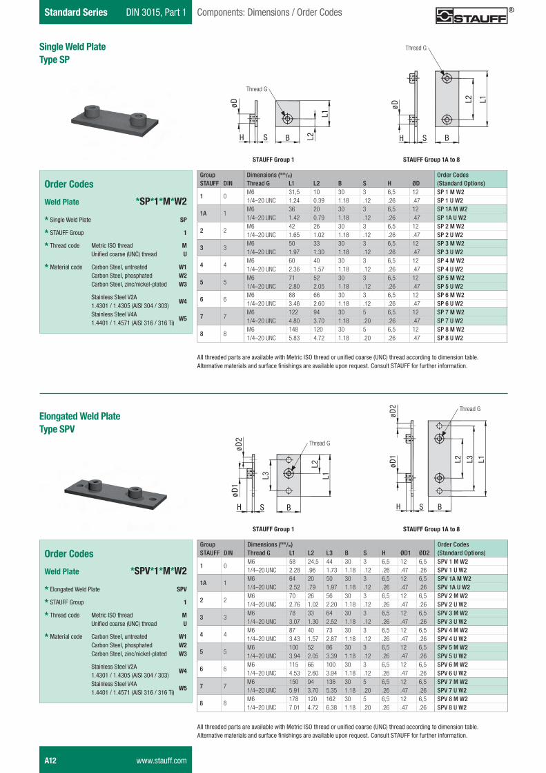
Single Weld PlateType SP
Order Codes
Weld Plate *SP*1*M*W2
* Single Weld Plate SP
* STAUFF Group 1
* Thread code Metric ISO thread M
Unified coarse (UNC) thread U
* Material code Carbon Steel, untreated W1 Carbon Steel, phosphated W2 Carbon Steel, zinc/nickel-plated W3
Stainless Steel V2A 1.4301 / 1.4305 (AISI 304 / 303)
W4
Stainless Steel V4A 1.4401 / 1.4571 (AISI 316 / 316 Ti)
W5
All threaded parts are available with Metric ISO thread or unified coarse (UNC) thread according to dimension table.Alternative materials and surface finishings are available upon request. Consult STAUFF for further information.
Group Dimensions (mm/in) Order CodesSTAUFF DIN Thread G L1 L2 L3 B S H ØD1 ØD2 (Standard Options)
1 0M6 58 24,5 44 30 3 6,5 12 6,5 SPV 1 M W21/4–20 UNC 2.28 .96 1.73 1.18 .12 .26 .47 .26 SPV 1 U W2
1A 1M6 64 20 50 30 3 6,5 12 6,5 SPV 1A M W21/4–20 UNC 2.52 .79 1.97 1.18 .12 .26 .47 .26 SPV 1A U W2
2 2M6 70 26 56 30 3 6,5 12 6,5 SPV 2 M W21/4–20 UNC 2.76 1.02 2.20 1.18 .12 .26 .47 .26 SPV 2 U W2
3 3M6 78 33 64 30 3 6,5 12 6,5 SPV 3 M W21/4–20 UNC 3.07 1.30 2.52 1.18 .12 .26 .47 .26 SPV 3 U W2
4 4M6 87 40 73 30 3 6,5 12 6,5 SPV 4 M W21/4–20 UNC 3.43 1.57 2.87 1.18 .12 .26 .47 .26 SPV 4 U W2
5 5M6 100 52 86 30 3 6,5 12 6,5 SPV 5 M W21/4–20 UNC 3.94 2.05 3.39 1.18 .12 .26 .47 .26 SPV 5 U W2
6 6M6 115 66 100 30 3 6,5 12 6,5 SPV 6 M W21/4–20 UNC 4.53 2.60 3.94 1.18 .12 .26 .47 .26 SPV 6 U W2
7 7M6 150 94 136 30 5 6,5 12 6,5 SPV 7 M W21/4–20 UNC 5.91 3.70 5.35 1.18 .20 .26 .47 .26 SPV 7 U W2
8 8M6 178 120 162 30 5 6,5 12 6,5 SPV 8 M W21/4–20 UNC 7.01 4.72 6.38 1.18 .20 .26 .47 .26 SPV 8 U W2
Elongated Weld PlateType SPV
Order Codes
Weld Plate *SPV*1*M*W2
* Elongated Weld Plate SPV
* STAUFF Group 1
* Thread code Metric ISO thread M
Unified coarse (UNC) thread U
* Material code Carbon Steel, untreated W1 Carbon Steel, phosphated W2 Carbon Steel, zinc/nickel-plated W3
Stainless Steel V2A 1.4301 / 1.4305 (AISI 304 / 303)
W4
Stainless Steel V4A 1.4401 / 1.4571 (AISI 316 / 316 Ti)
W5
All threaded parts are available with Metric ISO thread or unified coarse (UNC) thread according to dimension table.Alternative materials and surface finishings are available upon request. Consult STAUFF for further information.
ø D
B
L1
L 2SH
ø D
B
L 2
SH
L 1
STAUFF Group 1 STAUFF Group 1A to 8
ø D 2
B
L1L 2
SH
ø D 1
L 3
ø D 2
B
L 2
SH
ø D 1 L 3 L 1
STAUFF Group 1 STAUFF Group 1A to 8
Thread G
Thread G
Thread G
Thread G
A12 www.stauff.com
Schelle-2012-03-28-EN.indd 12 29.03.2012 10:10:41
STAU
FF
Clam
psA
DIN 3015, Part 1 Standard SeriesComponents: Dimensions / Order Codes
Twin Weld PlateType DSP
Group Dimensions (mm/in) Order CodesSTAUFF DIN Thread G L1 L2 L3 B S H ØD (Standard Options)
1 0M6 87 40 40 30 3 6.5 12 DSP 1/40 M W21/4–20 UNC 3.43 1.57 1.57 1.18 .12 .26 .47 DSP 1/40 U W2
1A 1M6 77 20 37 30 3 6.5 12 DSP 1A/37 M W21/4–20 UNC 3.03 .79 1.46 1.18 .12 .26 .47 DSP 1A/37 U W2
2 2M6 86 26 44 30 3 6.5 12 DSP 2/44 M W21/4–20 UNC 3.39 1.02 1.73 1.18 .12 .26 .47 DSP 2/44 U W2
3 3M6 102 33 52 30 3 6.5 12 DSP 3/52 M W21/4–20 UNC 4.02 1.30 2.05 1.18 .12 .26 .47 DSP 3/52 U W2
4 4M6 120 40 60 30 3 6.5 12 DSP 4/60 M W21/4–20 UNC 4.72 1.57 2.36 1.18 .12 .26 .47 DSP 4/60 U W2
5 5M6 145 52 75 30 3 6.5 12 DSP 5/75 M W21/4–20 UNC 5.71 2.05 2.95 1.18 .12 .26 .47 DSP 5/75 U W2
6 6M6 178 66 90 30 3 6.5 12 DSP 6/90 M W21/4–20 UNC 7.01 2.60 3.54 1.18 .12 .26 .47 DSP 6/90 U W2
All threaded parts are available with Metric ISO thread or unified coarse (UNC) thread according to dimension table.Alternative materials and surface finishings are available upon request. Consult STAUFF for further information.
Order Codes
Weld Plate *DSP*1/40*M*W2
* Twin Weld Plate DSP
* STAUFF Group 1
* Pipe center spacing L3 (mm) 40
* Thread code Metric ISO thread M
Unified coarse (UNC) thread U
* Material code Carbon Steel, untreated W1 Carbon Steel, phosphated W2 Carbon Steel, zinc/nickel-plated W3
Stainless Steel V2A 1.4301 / 1.4305 (AISI 304 / 303)
W4
Stainless Steel V4A 1.4401 / 1.4571 (AISI 316 / 316 Ti)
W5
Group Weld PlateType RAP
Group Dimensions (mm/in) Order CodesSTAUFF DIN Thread G L1 L2 L3 B S H ØD (Standard Options)
1 0M6 314 31 31 30 4 6,5 12 RAP 1/31/10 M W11/4–20 UNC 12.36 1.22 1.22 1.18 .16 .26 .47 RAP 1/31/10 U W1
1A 1M6 373 20 37 30 4 6,5 12 RAP 1A/37/10 M W11/4–20 UNC 14.69 .79 1.46 1.18 .16 .26 .47 RAP 1A/37/10 U W1
2 2M6 442 26 44 30 4 6,5 12 RAP 2/44/10 M W11/4–20 UNC 17.40 1.02 1.73 1.18 .16 .26 .47 RAP 2/44/10 U W1
3 3M6 521 33 52 30 4 6,5 12 RAP 3/52/10 M W11/4–20 UNC 20.51 1.30 2.05 1.18 .16 .26 .47 RAP 3/52/10 U W1
4 4M6 300 40 60 30 4 6,5 12 RAP 4/60/5 M W11/4–20 UNC 11.81 1.57 2.36 1.18 .16 .26 .47 RAP 4/60/5 U W1
5 5M6 378 52 75 30 4 6,5 12 RAP 5/75/5 M W11/4–20 UNC 14.88 2.05 2.95 1.18 .16 .26 .47 RAP 5/75/5 U W1
6 6M6 450 66 90 30 4 6,5 12 RAP 6/90/5 M W11/4–20 UNC 17.72 2.60 3.54 1.18 .16 .26 .47 RAP 6/90/5 U W1
All threaded parts are available with Metric ISO thread or unified coarse (UNC) thread according to dimension table.Alternative materials and surface finishings are available upon request. Consult STAUFF for further information.
Order Codes
Weld Plate *RAP*1/31/10*M*W1
* Group Weld Plate RAP
* STAUFF Group 1
* Pipe center spacing L3 (mm) 31
* Number of clamps 10
* Thread code Metric ISO thread M
Unified coarse (UNC) thread U
* Material code Carbon Steel, untreated W1 Carbon Steel, phosphated W2 Carbon Steel, zinc/nickel-plated W3
Stainless Steel V2A 1.4301 / 1.4305 (AISI 304 / 303)
W4
Stainless Steel V4A 1.4401 / 1.4571 (AISI 316 / 316 Ti)
W5
B
L 2
SH
ø D
23,5
L 1
L 3
B
L 2
SH
ø D
L 3 L 1
L 2
STAUFF Group 1 STAUFF Group 1A to 8
B
L 2
SH
ø D
L 3
L 1
B
L 2
SH
ø D
L 3
L 1
L 2
STAUFF Group 1 STAUFF Group 1A to 8
Thread G
Thread G
Thread G
Thread G
www.stauff.com A13
Schelle-2012-03-28-EN.indd 13 29.03.2012 10:10:45
Standard Series DIN 3015, Part 1 Components: Dimensions / Order Codes
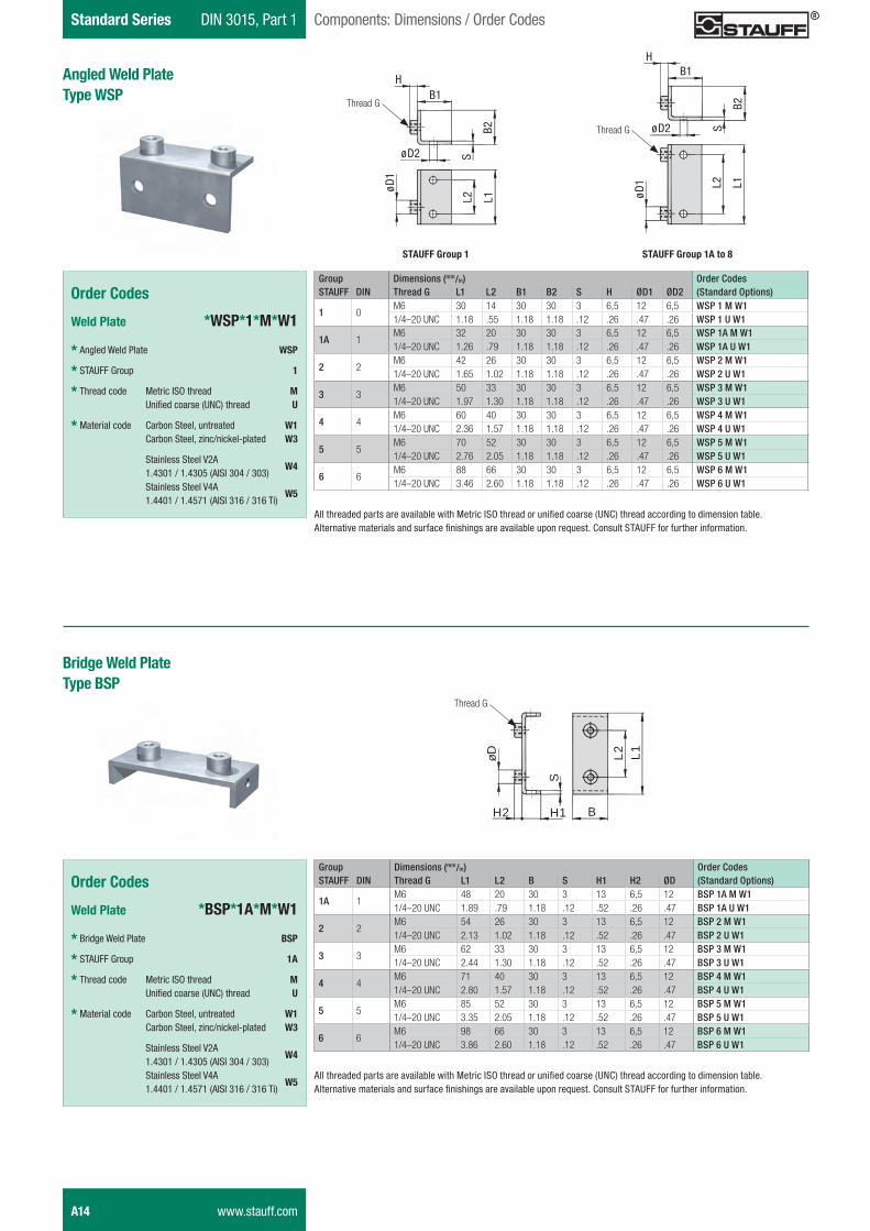
Group Dimensions (mm/in) Order CodesSTAUFF DIN Thread G L1 L2 B1 B2 S H ØD1 ØD2 (Standard Options)
1 0M6 30 14 30 30 3 6,5 12 6,5 WSP 1 M W11/4–20 UNC 1.18 .55 1.18 1.18 .12 .26 .47 .26 WSP 1 U W1
1A 1M6 32 20 30 30 3 6,5 12 6,5 WSP 1A M W11/4–20 UNC 1.26 .79 1.18 1.18 .12 .26 .47 .26 WSP 1A U W1
2 2M6 42 26 30 30 3 6,5 12 6,5 WSP 2 M W11/4–20 UNC 1.65 1.02 1.18 1.18 .12 .26 .47 .26 WSP 2 U W1
3 3M6 50 33 30 30 3 6,5 12 6,5 WSP 3 M W11/4–20 UNC 1.97 1.30 1.18 1.18 .12 .26 .47 .26 WSP 3 U W1
4 4M6 60 40 30 30 3 6,5 12 6,5 WSP 4 M W11/4–20 UNC 2.36 1.57 1.18 1.18 .12 .26 .47 .26 WSP 4 U W1
5 5M6 70 52 30 30 3 6,5 12 6,5 WSP 5 M W11/4–20 UNC 2.76 2.05 1.18 1.18 .12 .26 .47 .26 WSP 5 U W1
6 6M6 88 66 30 30 3 6,5 12 6,5 WSP 6 M W11/4–20 UNC 3.46 2.60 1.18 1.18 .12 .26 .47 .26 WSP 6 U W1
Angled Weld PlateType WSP
Order Codes
Weld Plate *WSP*1*M*W1
* Angled Weld Plate WSP
* STAUFF Group 1
* Thread code Metric ISO thread M
Unified coarse (UNC) thread U
* Material code Carbon Steel, untreated W1 Carbon Steel, zinc/nickel-plated W3
Stainless Steel V2A 1.4301 / 1.4305 (AISI 304 / 303)
W4
Stainless Steel V4A 1.4401 / 1.4571 (AISI 316 / 316 Ti)
W5
All threaded parts are available with Metric ISO thread or unified coarse (UNC) thread according to dimension table.Alternative materials and surface finishings are available upon request. Consult STAUFF for further information.
Group Dimensions (mm/in) Order CodesSTAUFF DIN Thread G L1 L2 B S H1 H2 ØD (Standard Options)
1A 1M6 48 20 30 3 13 6,5 12 BSP 1A M W11/4–20 UNC 1.89 .79 1.18 .12 .52 .26 .47 BSP 1A U W1
2 2M6 54 26 30 3 13 6,5 12 BSP 2 M W11/4–20 UNC 2.13 1.02 1.18 .12 .52 .26 .47 BSP 2 U W1
3 3M6 62 33 30 3 13 6,5 12 BSP 3 M W11/4–20 UNC 2.44 1.30 1.18 .12 .52 .26 .47 BSP 3 U W1
4 4M6 71 40 30 3 13 6,5 12 BSP 4 M W11/4–20 UNC 2.80 1.57 1.18 .12 .52 .26 .47 BSP 4 U W1
5 5M6 85 52 30 3 13 6,5 12 BSP 5 M W11/4–20 UNC 3.35 2.05 1.18 .12 .52 .26 .47 BSP 5 U W1
6 6M6 98 66 30 3 13 6,5 12 BSP 6 M W11/4–20 UNC 3.86 2.60 1.18 .12 .52 .26 .47 BSP 6 U W1
Bridge Weld PlateType BSP
Order Codes
Weld Plate *BSP*1A*M*W1
* Bridge Weld Plate BSP
* STAUFF Group 1A
* Thread code Metric ISO thread M
Unified coarse (UNC) thread U
* Material code Carbon Steel, untreated W1 Carbon Steel, zinc/nickel-plated W3
Stainless Steel V2A 1.4301 / 1.4305 (AISI 304 / 303)
W4
Stainless Steel V4A 1.4401 / 1.4571 (AISI 316 / 316 Ti)
W5All threaded parts are available with Metric ISO thread or unified coarse (UNC) thread according to dimension table.Alternative materials and surface finishings are available upon request. Consult STAUFF for further information.
L 2Sø D 2
B 1
B 2
ø D 1
L 1
H
L 2Sø D 2
B 1
B 2
ø D 1 L 1
H
STAUFF Group 1 STAUFF Group 1A to 8
B
L2
S
H2
øD
L1
H1
Thread G
Thread G
Thread G
A14 www.stauff.com
Schelle-2012-03-28-EN.indd 14 29.03.2012 10:10:48
STAU
FF
Clam
psA
DIN 3015, Part 1 Standard SeriesComponents: Dimensions / Order Codes
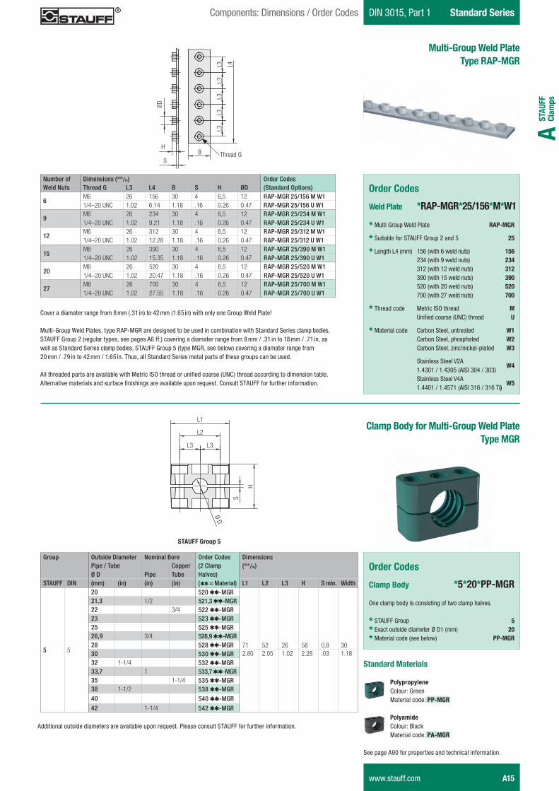
Multi-Group Weld PlateType RAP-MGR
Cover a diamater range from 8 mm (.31 in) to 42 mm (1.65 in) with only one Group Weld Plate!
Multi-Group Weld Plates, type RAP-MGR are designed to be used in combination with Standard Series clamp bodies, STAUFF Group 2 (regular types, see pages A6 ff.) covering a diamater range from 8 mm / .31 in to 18 mm / .71 in, as well as Standard Series clamp bodies, STAUFF Group 5 (type MGR, see below) covering a diamater range from 20 mm / .79 in to 42 mm / 1.65 in. Thus, all Standard Series metal parts of these groups can be used. All threaded parts are available with Metric ISO thread or unified coarse (UNC) thread according to dimension table.Alternative materials and surface finishings are available upon request. Consult STAUFF for further information.
Order Codes
Weld Plate *RAP-MGR*25/156*M*W1
* Multi Group Weld Plate RAP-MGR
* Suitable for STAUFF Group 2 and 5 25
* Length L4 (mm) 156 (with 6 weld nuts) 156 234 (with 9 weld nuts) 234 312 (with 12 weld nuts) 312 390 (with 15 weld nuts) 390 520 (with 20 weld nuts) 520 700 (with 27 weld nuts) 700
* Thread code Metric ISO thread M
Unified coarse (UNC) thread U
* Material code Carbon Steel, untreated W1 Carbon Steel, phosphated W2 Carbon Steel, zinc/nickel-plated W3
Stainless Steel V2A 1.4301 / 1.4305 (AISI 304 / 303)
W4
Stainless Steel V4A 1.4401 / 1.4571 (AISI 316 / 316 Ti)
W5
Clamp Body for Multi-Group Weld PlateType MGR
Additional outside diameters are available upon request. Please consult STAUFF for further information.
Number of Dimensions (mm/in) Order CodesWeld Nuts Thread G L3 L4 B S H ØD (Standard Options)
6M6 26 156 30 4 6,5 12 RAP-MGR 25/156 M W11/4–20 UNC 1.02 6.14 1.18 .16 0.26 0.47 RAP-MGR 25/156 U W1
9M6 26 234 30 4 6,5 12 RAP-MGR 25/234 M W11/4–20 UNC 1.02 9.21 1.18 .16 0.26 0.47 RAP-MGR 25/234 U W1
12M6 26 312 30 4 6,5 12 RAP-MGR 25/312 M W11/4–20 UNC 1.02 12.28 1.18 .16 0.26 0.47 RAP-MGR 25/312 U W1
15M6 26 390 30 4 6,5 12 RAP-MGR 25/390 M W11/4–20 UNC 1.02 15.35 1.18 .16 0.26 0.47 RAP-MGR 25/390 U W1
20M6 26 520 30 4 6,5 12 RAP-MGR 25/520 M W11/4–20 UNC 1.02 20.47 1.18 .16 0.26 0.47 RAP-MGR 25/520 U W1
27M6 26 700 30 4 6,5 12 RAP-MGR 25/700 M W11/4–20 UNC 1.02 27.55 1.18 .16 0.26 0.47 RAP-MGR 25/700 U W1
Order Codes
Clamp Body *5*20*PP-MGR
One clamp body is consisting of two clamp halves.
* STAUFF Group 5
* Exact outside diameter Ø D1 (mm) 20
* Material code (see below) PP-MGR
Standard Materials
Polypropylene Colour: Green Material code: PP-MGR
Polyamide Colour: Black Material code: PA-MGR
See page A90 for properties and technical information.
Group Outside Diameter Nominal Bore Order Codes DimensionsPipe / Tube Copper (2 Clamp (mm/in)Ø D Pipe Tube Halves)
STAUFF DIN (mm) (in) (in) (in) (QQ = Material) L1 L2 L3 H S min. Width
5 5
20 520 QQ-MGR
71 52 26 58 0,8 30
21,3 1/2 521,3 QQ-MGR22 3/4 522 QQ-MGR23 523 QQ-MGR25 525 QQ-MGR26,9 3/4 526,9 QQ-MGR28 528 QQ-MGR30 530 QQ-MGR 2.80 2.05 1.02 2.28 .03 1.1832 1-1/4 532 QQ-MGR33,7 1 533,7 QQ-MGR35 1-1/4 535 QQ-MGR38 1-1/2 538 QQ-MGR40 540 QQ-MGR42 1-1/4 542 QQ-MGR
STAUFF Group 5
L2
L1
L3 L3
Ø D
H
S
L3L3
L3L3
L3
L4
BS
H
ØD
Thread G
www.stauff.com A15
Schelle-2012-03-28-EN.indd 15 29.03.2012 10:10:49
Standard Series DIN 3015, Part 1 Components: Dimensions / Order Codes
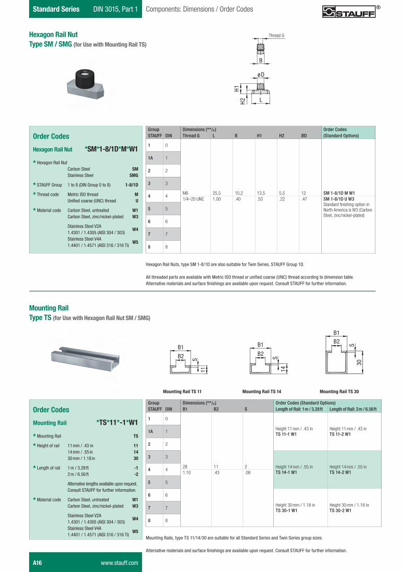
Hexagon Rail Nut Type SM / SMG (for Use with Mounting Rail TS)
Mounting RailType TS (for Use with Hexagon Rail Nut SM / SMG)
Order Codes
Hexagon Rail Nut *SM*1-8/1D*M*W1
* Hexagon Rail Nut Carbon Steel SM Stainless Steel SMG
* STAUFF Group 1 to 8 (DIN Group 0 to 8) 1-8/1D
* Thread code Metric ISO thread M
Unified coarse (UNC) thread U
* Material code Carbon Steel, untreated W1 Carbon Steel, zinc/nickel-plated W3
Stainless Steel V2A 1.4301 / 1.4305 (AISI 304 / 303)
W4
Stainless Steel V4A 1.4401 / 1.4571 (AISI 316 / 316 Ti)
W5
Mounting Rails, type TS 11/14/30 are suitable for all Standard Series and Twin Series group sizes.
Alternative materials and surface finishings are available upon request. Consult STAUFF for further information.
Order Codes
Mounting Rail *TS*11*-1*W1
* Mounting Rail TS
* Height of rail 11 mm / .43 in 11 14 mm / .55 in 14 30 mm / 1.18 in 30
* Length of rail 1 m / 3.28 ft -1 2 m / 6.56 ft -2
Alternative lengths available upon request. Consult STAUFF for further information.
* Material code Carbon Steel, untreated W1 Carbon Steel, zinc/nickel-plated W3
Stainless Steel V2A 1.4301 / 1.4305 (AISI 304 / 303)
W4
Stainless Steel V4A 1.4401 / 1.4571 (AISI 316 / 316 Ti)
W5
Group Dimensions (mm/in) Order CodesSTAUFF DIN Thread G L B H1 H2 ØD (Standard Options)
1 0
M6 25,5 10,2 13,5 5,5 12 SM 1-8/1D M W1
1A 1
2 2
3 3
4 41/4–20 UNC 1.00 .40 .53 .22 .47 SM 1-8/1D U W3
Standard finishing option in North America is W3 (Carbon Steel, zinc/nickel-plated)
5 5
6 6
7 7
8 8
Hexagon Rail Nuts, type SM 1-8/1D are also suitable for Twin Series, STAUFF Group 1D.
All threaded parts are available with Metric ISO thread or unified coarse (UNC) thread according to dimension table.Alternative materials and surface finishings are available upon request. Consult STAUFF for further information.
S
B 1
11
B 2
Mounting Rail TS 11 Mounting Rail TS 14 Mounting Rail TS 30
B 1
B 2
S14
S
B 1
30
B 2
øD
H 2
H 1
L
B
M6 Thread G
Group Dimensions (mm/in) Order Codes (Standard Options)STAUFF DIN B1 B2 S Length of Rail: 1 m / 3.28 ft Length of Rail: 2 m / 6.56 ft
1 0
28 11 2
Height 11 mm / .43 in TS 11-1 W1
Height 11 mm / .43 inTS 11-2 W11A 1
2 2
3 3
Height 14 mm / .55 in TS 14-1 W1
Height 14 mm / .55 inTS 14-2 W14 4
1.10 .43 .08
5 5
6 6
Height 30 mm / 1.18 inTS 30-1 W1
Height 30 mm / 1.18 inTS 30-2 W17 7
8 8
A16 www.stauff.com
Schelle-2012-03-28-EN.indd 16 29.03.2012 10:10:53
STAU
FF
Clam
psA
DIN 3015, Part 1 Standard SeriesComponents: Dimensions / Order Codes
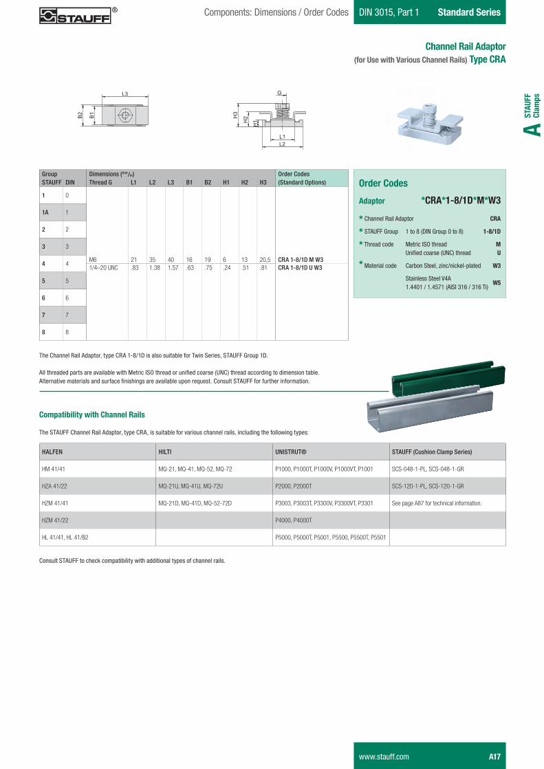
Channel Rail Adaptor(for Use with Various Channel Rails) Type CRA
The Channel Rail Adaptor, type CRA 1-8/1D is also suitable for Twin Series, STAUFF Group 1D.
All threaded parts are available with Metric ISO thread or unified coarse (UNC) thread according to dimension table.Alternative materials and surface finishings are available upon request. Consult STAUFF for further information.
Order Codes
Adaptor *CRA*1-8/1D*M*W3
* Channel Rail Adaptor CRA
* STAUFF Group 1 to 8 (DIN Group 0 to 8) 1-8/1D
* Thread code Metric ISO thread M
Unified coarse (UNC) thread U
* Material code Carbon Steel, zinc/nickel-plated W3
Stainless Steel V4A 1.4401 / 1.4571 (AISI 316 / 316 Ti)
W5
Compatibility with Channel Rails
The STAUFF Channel Rail Adaptor, type CRA, is suitable for various channel rails, including the following types:
HALFEN HILTI UNISTRUT® STAUFF (Cushion Clamp Series)
HM 41/41 MQ-21, MQ-41, MQ-52, MQ-72 P1000, P1000T, P1000V, P1000VT, P1001 SCS-048-1-PL, SCS-048-1-GR
HZA 41/22 MQ-21U, MQ-41U, MQ-72U P2000, P2000T SCS-120-1-PL, SCS-120-1-GR
HZM 41/41 MQ-21D, MQ-41D, MQ-52-72D P3003, P3003T, P3300V, P3300VT, P3301 See page A87 for technical information.
HZM 41/22 P4000, P4000T
HL 41/41, HL 41/B2 P5000, P5000T, P5001, P5500, P5500T, P5501
Consult STAUFF to check compatibility with additional types of channel rails.
Group Dimensions (mm/in) Order CodesSTAUFF DIN Thread G L1 L2 L3 B1 B2 H1 H2 H3 (Standard Options)
1 0
M6 21 35 40 16 19 6 13 20,5 CRA 1-8/1D M W3
1A 1
2 2
3 3
4 41/4–20 UNC .83 1.38 1.57 .63 .75 .24 .51 .81 CRA 1-8/1D U W3
5 5
6 6
7 7
8 8
www.stauff.com A17
Schelle-2012-03-28-EN.indd 17 29.03.2012 10:10:54
Standard Series DIN 3015, Part 1 Components: Dimensions / Order Codes
Group Dimensions (mm/in) Order CodesSTAUFF DIN L1 L2 B S ØD (Standard Options)
1 028 9,5 30 3 7
DP 1 W31.10 .37 1.18 .12 .28
1A 134 20 30 3 7
DP 1A W31.34 .79 1.18 .12 .28
2 240,5 26 30 3 7
DP 2 W31.59 1.02 1.18 .12 .28
3 348 33 30 3 7
DP 3 W31.89 1.30 1.18 .12 .28
4 457 40 30 3 7
DP 4 W32.24 1.57 1.18 .12 .28
5 570 52 30 3 7
DP 5 W32.76 2.05 1.18 .12 .28
6 686 66 30 3 7
DP 6 W33.39 2.60 1.18 .12 .28
7 7118 94 30 5 7
DP 7 W34.65 3.70 1.18 .20 .28
8 8144 120 30 5 7
DP 8 W35.67 4.72 1.18 .20 .28
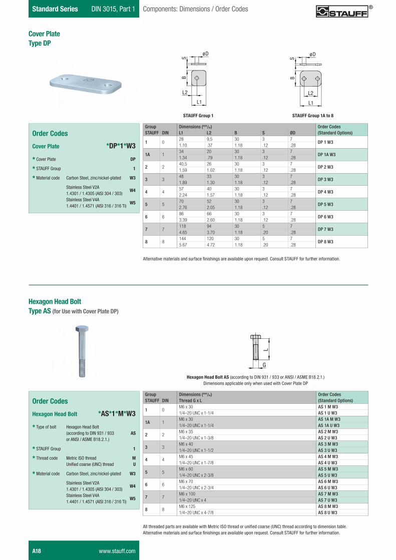
Cover PlateType DP
Order Codes
Cover Plate *DP*1*W3
* Cover Plate DP
* STAUFF Group 1
* Material code Carbon Steel, zinc/nickel-plated W3
Stainless Steel V2A 1.4301 / 1.4305 (AISI 304 / 303)
W4
Stainless Steel V4A 1.4401 / 1.4571 (AISI 316 / 316 Ti)
W5
Alternative materials and surface finishings are available upon request. Consult STAUFF for further information.
Group Dimensions (mm/in) Order CodesSTAUFF DIN Thread G x L (Standard Options)
1 0M6 x 30 AS 1 M W31/4–20 UNC x 1-1/4 AS 1 U W3
1A 1M6 x 30 AS 1A M W31/4–20 UNC x 1-1/4 AS 1A U W3
2 2M6 x 35 AS 2 M W31/4–20 UNC x 1-3/8 AS 2 U W3
3 3M6 x 40 AS 3 M W31/4–20 UNC x 1-1/2 AS 3 U W3
4 4M6 x 45 AS 4 M W31/4–20 UNC x 1-7/8 AS 4 U W3
5 5M6 x 60 AS 5 M W31/4–20 UNC x 2-3/8 AS 5 U W3
6 6M6 x 70 AS 6 M W31/4–20 UNC x 2-3/4 AS 6 U W3
7 7M6 x 100 AS 7 M W31/4–20 UNC x 4 AS 7 U W3
8 8M6 x 125 AS 8 M W31/4–20 UNC x 4-7/8 AS 8 U W3
Order Codes
Hexagon Head Bolt *AS*1*M*W3
* Type of bolt Hexagon Head Bolt (according to DIN 931 / 933 AS
or ANSI / ASME B18.2.1.)
* STAUFF Group 1
* Thread code Metric ISO thread M
Unified coarse (UNC) thread U
* Material code Carbon Steel, zinc/nickel-plated W3
Stainless Steel V2A 1.4301 / 1.4305 (AISI 304 / 303)
W4
Stainless Steel V4A 1.4401 / 1.4571 (AISI 316 / 316 Ti)
W5
All threaded parts are available with Metric ISO thread or unified coarse (UNC) thread according to dimension table.Alternative materials and surface finishings are available upon request. Consult STAUFF for further information.
Hexagon Head BoltType AS (for Use with Cover Plate DP)
L 2
S
ø D
L 1
B
L 2
S
ø D
B
L 1
STAUFF Group 1 STAUFF Group 1A to 8
L
G
Hexagon Head Bolt AS (according to DIN 931 / 933 or ANSI / ASME B18.2.1.)Dimensions applicable only when used with Cover Plate DP
A18 www.stauff.com
Schelle-2012-03-28-EN.indd 18 29.03.2012 10:10:57
STAU
FF
Clam
psA
DIN 3015, Part 1 Standard SeriesComponents: Dimensions / Order Codes
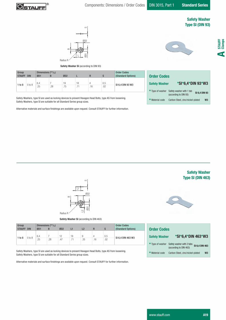
Group Dimensions (mm/in) Order CodesSTAUFF DIN ØD1 B ØD2 L R S (Standard Options)
1 to 8 0 to 86,4 7 19 18 4 0,5
SI 6,4 DIN 93 W3.25 .28 .75 .71 .16 .02
Safety WasherType SI (DIN 93)
Order Codes
Safety Washer *SI*6,4*DIN 93*W3
* Type of washer Safety washer with 1 tab (according to DIN 93)
SI 6,4 DIN 93
* Material code Carbon Steel, zinc/nickel-plated W3
Safety WasherType SI (DIN 463)
Order Codes
Safety Washer *SI*6,4*DIN 463*W3
* Type of washer Safety washer with 2 tabs (according to DIN 463)
SI 6,4 DIN 463
* Material code Carbon Steel, zinc/nickel-plated W3
Safety Washer SI (according to DIN 93)
Radius R
ØD1L
ØD2
B
S
Safety Washers, type SI are used as locking devices to prevent Hexagon Head Bolts, type AS from loosening.Safety Washers, type SI are suitable for all Standard Series group sizes.
Alternative materials and surface finishings are available upon request. Consult STAUFF for further information.
Group Dimensions (mm/in) Order CodesSTAUFF DIN ØD1 B ØD2 L1 L2 R S (Standard Options)
1 to 8 0 to 86,4 7 12 18 9 4 0,5
SI 6,4 DIN 463 W3.25 .28 .47 .71 .35 .16 .02
Safety Washer SI (according to DIN 463)
Radius R
ØD1
L1
ØD2
B
S
Safety Washers, type SI are used as locking devices to prevent Hexagon Head Bolts, type AS from loosening.Safety Washers, type SI are suitable for all Standard Series group sizes.
Alternative materials and surface finishings are available upon request. Consult STAUFF for further information.
L2
www.stauff.com A19
Schelle-2012-03-28-EN.indd 19 29.03.2012 10:10:58
Standard Series DIN 3015, Part 1 Components: Dimensions / Order Codes
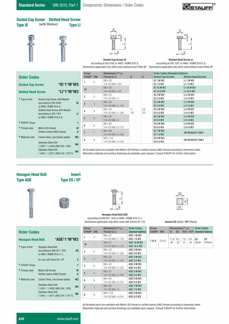
Group Dimensions (mm/in) Order Codes (Standard Options)STAUFF DIN Thread G x L D S Socket Cap Screws Slotted Head Screws
1 0M6 x 20
11 0,8
IS 1 M W3 LI 1 M W31/4–20 UNC x 3/4 IS 1 U W3 LI 1 U W3
1A 1M6 x 20 IS 1A M W3 LI 1A M W31/4–20 UNC x 3/4 IS 1A U W3 LI 1A U W3
2 2M6 x 25 IS 2 M W3 LI 2 M W31/4–20 UNC x 1 IS 2 U W3 LI 2 U W3
3 3M6 x 30 IS 3 M W3 LI 3 M W31/4–20 UNC x 1-1/8 IS 3 U W3 LI 3 U W3
4 4M6 x 35 IS 4 M W3 LI 4 M W31/4–20 UNC x 1-3/8 .43 .03 IS 4 U W3 LI 4 U W3
5 5M6 x 50 IS 5 M W3 LI 5 M W31/4–20 UNC x 2 IS 5 U W3 LI 5 U W3
6 6M6 x 60 IS 6 M W3 LI 6 M W31/4–20 UNC x 2-1/2 IS 6 U W3 LI 6 U W3
7 7M6 x 90 IS 7 M W3
ON REQUEST ONLY1/4–20 UNC x 3-3/8 IS 7 U W3
8 8M6 x 110 IS 8 M W3
ON REQUEST ONLY1/4–20 UNC x 4-3/8 IS 8 U W3
All threaded parts are available with Metric ISO thread or unified coarse (UNC) thread according to dimension table.Alternative materials and surface finishings are available upon request. Consult STAUFF for further information.
All threaded parts are available with Metric ISO thread or unified coarse (UNC) thread according to dimension table.Alternative materials and surface finishings are available upon request. Consult STAUFF for further information.
Group Dimensions (mm/in) Order CodesSTAUFF DIN Thread G x L (Standard Options)
1 0M6 x 27 ASE 1 M W31/4–20 UNC x 1-1/8 ASE 1 U W3
1A 1M6 x 27 ASE 1A M W31/4–20 UNC x 1-1/8 ASE 1A U W3
2 2M6 x 32 ASE 2 M W31/4–20 UNC x 1-3/8 ASE 2 U W3
3 3M6 x 35 ASE 3 M W31/4–20 UNC x 1-3/8 ASE 3 U W3
4 4M6 x 42 ASE 4 M W31/4–20 UNC x 1-5/8 ASE 4 U W3
5 5M6 x 57 ASE 5 M W31/4–20 UNC x 2-3/8 ASE 5 U W3
6 6M6 x 65 ASE 6 M W31/4–20 UNC x 2-3/4 ASE 6 U W3
7 7M6 x 95 ASE 7 M W31/4–20 UNC x 4 ASE 7 U W3
8 8M6 x 118 ASE 8 M W31/4–20 UNC x 4-3/4 ASE 8 U W3
Group Dimensions (mm/in) Order CodesSTAUFF DIN D1 D2 H ES H EP (Standard Options)
1 to 8 0 to 811,8 6,5 7,8 8,6 ES
(Steel)EP(Plastic).46 .26 .31 .34
S
D
L
G
Socket Cap Screw IS (according to ISO 4762 or ANSI / ASME B18.3)
Dimensions applicable only when used without Cover Plate DP
S
D
L
G
Slotted Head Screw LI (according to ISO 1207 or ANSI / ASME B18.6.3)
Dimensions applicable only when used without Cover Plate DP
L
G
Hexagon Head Bolt ASE (according to DIN 931 / 933 or ANSI / ASME B18.2.1.)
Dimensions applicable only when used with Inserts EP / ES
H
D1
D2
Inserts ES (Steel) / EP (Plastic)
Socket Cap ScrewType IS
Slotted Head ScrewType LI
Order Codes
Socket Cap Screw *IS*1*M*W3
Slotted Head Screw *LI*1*M*W3
* Type of bolt Socket Cap Screw with Washer (according to ISO 4762 IS
or ANSI / ASME B18.3) Slotted Head Screw with Washer (according to ISO 1207 LI or ANSI / ASME B18.6.3)
* STAUFF Group 1
* Thread code Metric ISO thread M
Unified coarse (UNC) thread U
* Material code Carbon Steel, zinc/nickel-plated W3
Stainless Steel V2A 1.4301 / 1.4305 (AISI 304 / 303)
W4
Stainless Steel V4A 1.4401 / 1.4571 (AISI 316 / 316 Ti)
W5
InsertType ES / EP
Hexagon Head BoltType ASE
Order Codes
Hexagon Head Bolt *ASE*1*M*W3
* Type of bolt Hexagon Head Bolt (according to DIN 931 / 933 AS or ANSI / ASME B18.2.1.) for use with Insert ES / EP E
* STAUFF Group 1
* Thread code Metric ISO thread M
Unified coarse (UNC) thread U
* Material code Carbon Steel, zinc/nickel-plated W3
Stainless Steel V2A 1.4301 / 1.4305 (AISI 304 / 303)
W4
Stainless Steel V4A 1.4401 / 1.4571 (AISI 316 / 316 Ti)
W5
(with Washer)
A20 www.stauff.com
Schelle-2012-03-28-EN.indd 20 29.03.2012 10:11:00
STAU
FF
Clam
psA
DIN 3015, Part 1 Standard SeriesComponents: Dimensions / Order Codes
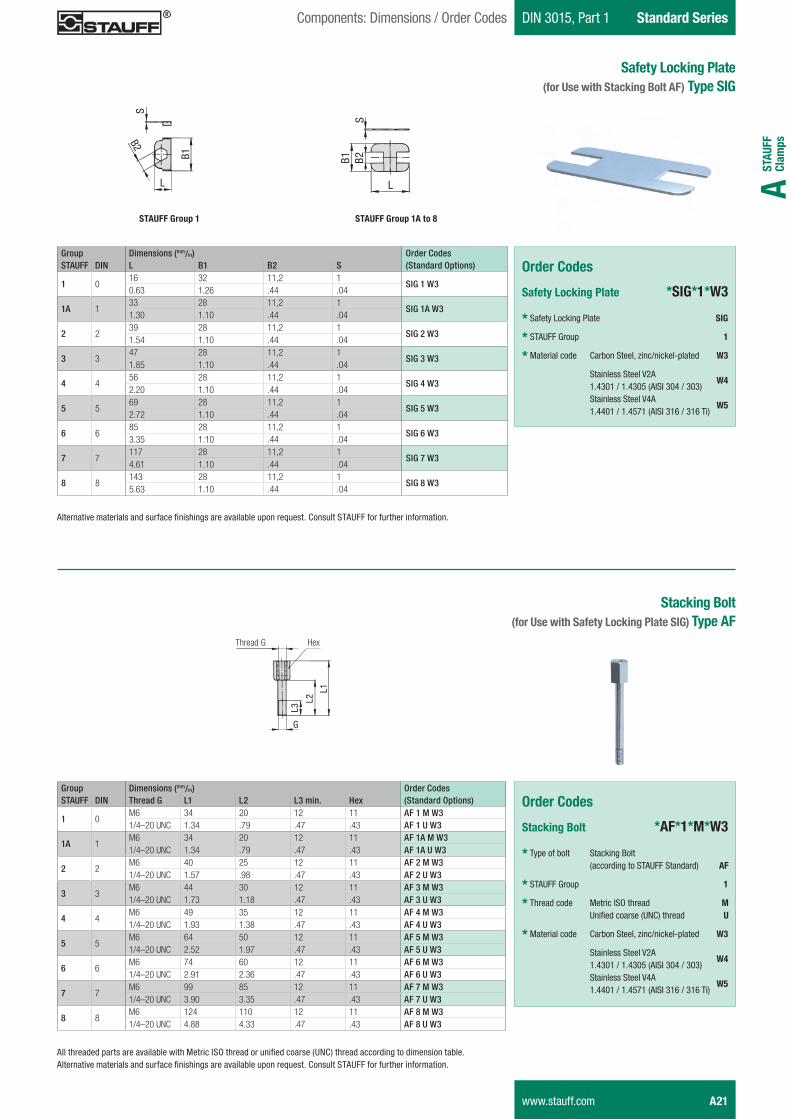
Group Dimensions (mm/in) Order CodesSTAUFF DIN L B1 B2 S (Standard Options)
1 016 32 11,2 1
SIG 1 W30.63 1.26 .44 .04
1A 133 28 11,2 1
SIG 1A W31.30 1.10 .44 .04
2 239 28 11,2 1
SIG 2 W31.54 1.10 .44 .04
3 347 28 11,2 1
SIG 3 W31.85 1.10 .44 .04
4 456 28 11,2 1
SIG 4 W32.20 1.10 .44 .04
5 569 28 11,2 1
SIG 5 W32.72 1.10 .44 .04
6 685 28 11,2 1
SIG 6 W33.35 1.10 .44 .04
7 7117 28 11,2 1
SIG 7 W34.61 1.10 .44 .04
8 8143 28 11,2 1
SIG 8 W35.63 1.10 .44 .04
Safety Locking Plate(for Use with Stacking Bolt AF) Type SIG
Order Codes
Safety Locking Plate *SIG*1*W3
* Safety Locking Plate SIG
* STAUFF Group 1
* Material code Carbon Steel, zinc/nickel-plated W3
Stainless Steel V2A 1.4301 / 1.4305 (AISI 304 / 303)
W4
Stainless Steel V4A 1.4401 / 1.4571 (AISI 316 / 316 Ti)
W5
Alternative materials and surface finishings are available upon request. Consult STAUFF for further information.
Order Codes
Stacking Bolt *AF*1*M*W3
* Type of bolt Stacking Bolt (according to STAUFF Standard) AF
* STAUFF Group 1
* Thread code Metric ISO thread M
Unified coarse (UNC) thread U
* Material code Carbon Steel, zinc/nickel-plated W3
Stainless Steel V2A 1.4301 / 1.4305 (AISI 304 / 303)
W4
Stainless Steel V4A 1.4401 / 1.4571 (AISI 316 / 316 Ti)
W5
All threaded parts are available with Metric ISO thread or unified coarse (UNC) thread according to dimension table.Alternative materials and surface finishings are available upon request. Consult STAUFF for further information.
Stacking Bolt (for Use with Safety Locking Plate SIG) Type AF
Group Dimensions (mm/in) Order CodesSTAUFF DIN Thread G L1 L2 L3 min. Hex (Standard Options)
1 0M6 34 20 12 11 AF 1 M W31/4–20 UNC 1.34 .79 .47 .43 AF 1 U W3
1A 1M6 34 20 12 11 AF 1A M W31/4–20 UNC 1.34 .79 .47 .43 AF 1A U W3
2 2M6 40 25 12 11 AF 2 M W31/4–20 UNC 1.57 .98 .47 .43 AF 2 U W3
3 3M6 44 30 12 11 AF 3 M W31/4–20 UNC 1.73 1.18 .47 .43 AF 3 U W3
4 4M6 49 35 12 11 AF 4 M W31/4–20 UNC 1.93 1.38 .47 .43 AF 4 U W3
5 5M6 64 50 12 11 AF 5 M W31/4–20 UNC 2.52 1.97 .47 .43 AF 5 U W3
6 6M6 74 60 12 11 AF 6 M W31/4–20 UNC 2.91 2.36 .47 .43 AF 6 U W3
7 7M6 99 85 12 11 AF 7 M W31/4–20 UNC 3.90 3.35 .47 .43 AF 7 U W3
8 8M6 124 110 12 11 AF 8 M W31/4–20 UNC 4.88 4.33 .47 .43 AF 8 U W3
B2
B1
S
L
STAUFF Group 1
SB 2B 1
L
STAUFF Group 1A to 8
L 2
SW
L 3
L 1
G
GThread G Hex
www.stauff.com A21
Schelle-2012-03-28-EN.indd 21 29.03.2012 10:11:04
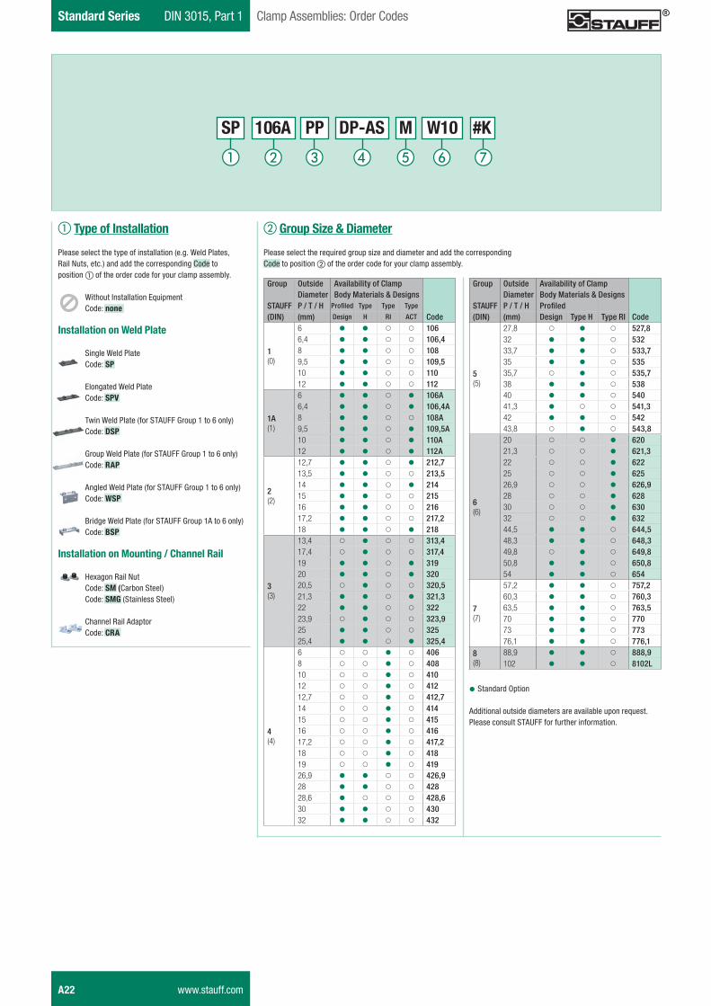
Standard Series DIN 3015, Part 1 Clamp Assemblies: Order Codes
b Group Size & Diameter
Please select the required group size and diameter and add the corresponding Code to position b of the order code for your clamp assembly.
�Standard Option
Additional outside diameters are available upon request. Please consult STAUFF for further information.
Group Outside Availability of ClampDiameter Body Materials & Designs
STAUFF P / T / H Profiled(DIN) (mm) Design Type H Type RI Code
5(5)
27,8 � � � 527,832 � � � 53233,7 � � � 533,735 � � � 53535,7 � � � 535,738 � � � 53840 � � � 54041,3 � � � 541,342 � � � 54243,8 � � � 543,8
6(6)
20 � � � 62021,3 � � � 621,322 � � � 62225 � � � 62526,9 � � � 626,928 � � � 62830 � � � 63032 � � � 63244,5 � � � 644,548,3 � � � 648,349,8 � � � 649,850,8 � � � 650,854 � � � 654
7(7)
57,2 � � � 757,260,3 � � � 760,363,5 � � � 763,570 � � � 77073 � � � 77376,1 � � � 776,1
8(8)
88,9 � � � 888,9102 � � � 8102L
SP 106A PP DP-AS M W10 #K
A22 www.stauff.com
a Type of Installation
Please select the type of installation (e.g. Weld Plates, Rail Nuts, etc.) and add the corresponding Code toposition a of the order code for your clamp assembly.
Without Installation Equipment Code: none
Installation on Weld Plate
Single Weld Plate Code: SP
Elongated Weld Plate Code: SPV
Twin Weld Plate (for STAUFF Group 1 to 6 only) Code: DSP
Group Weld Plate (for STAUFF Group 1 to 6 only) Code: RAP
Angled Weld Plate (for STAUFF Group 1 to 6 only) Code: WSP
Bridge Weld Plate (for STAUFF Group 1A to 6 only) Code: BSP
Installation on Mounting / Channel Rail
Hexagon Rail Nut Code: SM (Carbon Steel) Code: SMG (Stainless Steel)
Channel Rail Adaptor Code: CRA
Group Outside Availability of ClampDiameter Body Materials & Designs
STAUFF P / T / H Profiled Type Type Type
(DIN) (mm) Design H RI ACT Code
1(0)
6 � � � � 1066,4 � � � � 106,48 � � � � 1089,5 � � � � 109,510 � � � � 11012 � � � � 112
1A(1)
6 � � � � 106A6,4 � � � � 106,4A8 � � � � 108A9,5 � � � � 109,5A10 � � � � 110A12 � � � � 112A
2(2)
12,7 � � � � 212,713,5 � � � � 213,514 � � � � 21415 � � � � 21516 � � � � 21617,2 � � � � 217,218 � � � � 218
3(3)
13,4 � � � � 313,417,4 � � � � 317,419 � � � � 31920 � � � � 32020,5 � � � � 320,521,3 � � � � 321,322 � � � � 32223,9 � � � � 323,925 � � � � 32525,4 � � � � 325,4
4(4)
6 � � � � 4068 � � � � 40810 � � � � 41012 � � � � 41212,7 � � � � 412,714 � � � � 41415 � � � � 41516 � � � � 41617,2 � � � � 417,218 � � � � 41819 � � � � 41926,9 � � � � 426,928 � � � � 42828,6 � � � � 428,630 � � � � 43032 � � � � 432
Schelle-2012-03-28-EN.indd 22 29.03.2012 10:11:05
STAU
FF
Clam
psA
DIN 3015, Part 1 Standard SeriesClamp Assemblies: Order Codes
c Clamp Body Design & Material
Please select the design and material of your clamp body and add the corresponding Code to position c of the order code for your clamp assembly.
Please check the availability of the selected clamp body design and material according to the matrix table in b.
Profiled Design
Polypropylene Code: PP
Polyamide Code: PA
Thermoplastic Elastomer (87 Shore-A) Code: SA
Aluminium Code: AL (for STAUFF Group 1A to 6 only)
Type H (Smooth)
Polypropylene Code: PPH
Polyamide Code: PAH
Thermoplastic Elastomer (87 Shore-A) Code: SAH
Type RI (with Rubber Insert)
Polypropylene Code: PPR (for STAUFF Group 4 and 6 only)
Polyamide Code: PAR (for STAUFF Group 4 and 6 only)
Typ ACT (Anti Corrosion Technology)
Flame-retardant Polypropylene (PPV0) with integrated rubber strips made of Anti-Corrosion Elastomer (ACE) Code: ACT (for STAUFF Group 1A, 2 and 3 only)
See page A90 for material properties and technical information.
Please consult STAUFF for further details on fire-proof clamp body materials, tested and approved according to several international fire-protection standards.
d Mounting & Fitting Combination
Please select the mounting and fitting combination (e.g. bolts, screws, cover plates, etc.) and add the corresponding Code to position d of the order code for your clamp assembly.
Installation with Cover Plate and Bolts
Cover Plate DP with Hexagon Head Bolts ASCode: DP-AS
Cover Plate DP with Socket Cap Screws ISCode: DP-IS
Installation with Locking Plate and Bolts
Safety Locking Plate SIG withStacking Bolts AFCode: SIG-AF
Installation with Inserts and Bolts
Inserts EP (Plastic) withHexagon Head Bolts ASECode: EP-AS
Inserts ES (Steel) withHexagon Head Bolts ASECode: ES-AS
Installation with Bolts only
Socket Cap Screws IS with Washers Code: IS
Slotted Head Screws LI with WashersCode: LI (for STAUFF Group 1 to 6 only)
f Material & Surface Finishing
Please select the required material & surface finishing of the metal parts and add the corresponding Code to position f of the order code for your clamp assembly.
Metal parts made of Carbon Steel, untreated W1
Metal parts made of Carbon Steel, phosphated W2
Metal parts made of Carbon Steel, zinc/nickel-plated W3
Metal parts made of Stainless Steel V2A 1.4301 / 1.4305 (AISI 304 / 303)
W4
Metal parts made of Stainless Steel V4A1.4401 / 1.4571 (AISI 316 / 316 Ti)
W5
Weld Plate made of Carbon Steel, phosphated; Other metal parts made of Carbon Steel, zinc/nickel-plated
W10
Rail Nuts made of Carbon Steel, untreated; Other metal parts made of Carbon Steel, zinc/nickel-plated
W11
Individual combinations of alternative materials and surface finishings are available upon request. Consult STAUFF for further information.
g Assembling & Kitting
If required, please select an additional assembling and kitting option and add the corresponding Code to the last position of the order code for your clamp assembly.
Components supplied separately Code: none (standard option)
Components assembled Code: #A (special option)
Components packed in kitsCode: #K (special option)
e Thread Type
Please select the required thread type and add the corresponding Code to position e of the order code for your clamp assembly.
Metric ISO threadCode: M
Unified coarse (UNC) thread Code: U
All threaded parts are available with Metric ISO thread or unified coarse (UNC) thread according to dimension table.
www.stauff.com A23
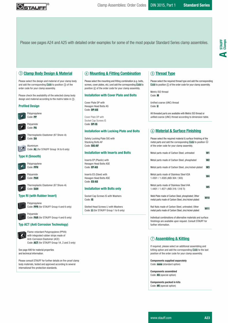
Please see pages A24 and A25 with detailed order examples for some of the most popular Standard Series clamp assemblies.
Schelle-2012-03-28-EN.indd 23 29.03.2012 10:11:07
Standard Series DIN 3015, Part 1 Clamp Assemblies: Order Examples
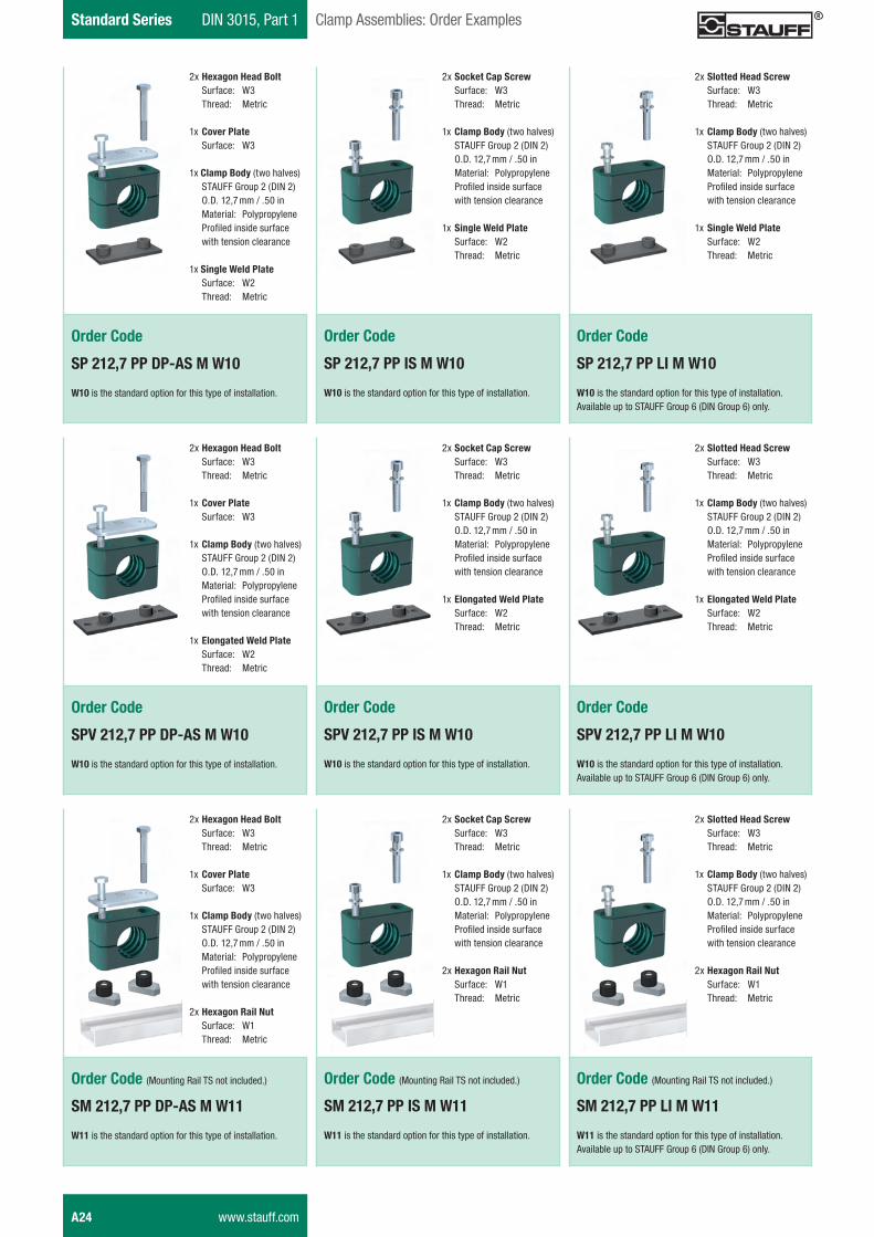
Order Code
SP 212,7 PP DP-AS M W10
W10 is the standard option for this type of installation.
2x Hexagon Head Bolt Surface: W3 Thread: Metric
1x Cover Plate Surface: W3
1x Clamp Body (two halves) STAUFF Group 2 (DIN 2) O.D. 12,7 mm / .50 in Material: Polypropylene Profi led inside surface with tension clearance
1x Single Weld Plate Surface: W2 Thread: Metric
Order Code
SP 212,7 PP IS M W10
W10 is the standard option for this type of installation.
2x Socket Cap Screw Surface: W3 Thread: Metric
1x Clamp Body (two halves) STAUFF Group 2 (DIN 2) O.D. 12,7 mm / .50 in Material: Polypropylene Profi led inside surface with tension clearance
1x Single Weld Plate Surface: W2 Thread: Metric
Order Code
SP 212,7 PP LI M W10
W10 is the standard option for this type of installation.Available up to STAUFF Group 6 (DIN Group 6) only.
2x Slotted Head Screw Surface: W3 Thread: Metric
1x Clamp Body (two halves) STAUFF Group 2 (DIN 2) O.D. 12,7 mm / .50 in Material: Polypropylene Profi led inside surface with tension clearance
1x Single Weld Plate Surface: W2 Thread: Metric
Order Code
SPV 212,7 PP DP-AS M W10
W10 is the standard option for this type of installation.
2x Hexagon Head Bolt Surface: W3 Thread: Metric
1x Cover Plate Surface: W3
1x Clamp Body (two halves) STAUFF Group 2 (DIN 2) O.D. 12,7 mm / .50 in Material: Polypropylene Profi led inside surface with tension clearance
1x Elongated Weld Plate Surface: W2 Thread: Metric
Order Code
SPV 212,7 PP IS M W10
W10 is the standard option for this type of installation.
2x Socket Cap Screw Surface: W3 Thread: Metric
1x Clamp Body (two halves) STAUFF Group 2 (DIN 2) O.D. 12,7 mm / .50 in Material: Polypropylene Profi led inside surface with tension clearance
1x Elongated Weld Plate Surface: W2 Thread: Metric
Order Code
SPV 212,7 PP LI M W10
W10 is the standard option for this type of installation.Available up to STAUFF Group 6 (DIN Group 6) only.
2x Slotted Head Screw Surface: W3 Thread: Metric
1x Clamp Body (two halves) STAUFF Group 2 (DIN 2) O.D. 12,7 mm / .50 in Material: Polypropylene Profi led inside surface with tension clearance
1x Elongated Weld Plate Surface: W2 Thread: Metric
Order Code (Mounting Rail TS not included.)
SM 212,7 PP DP-AS M W11
W11 is the standard option for this type of installation.
2x Hexagon Head Bolt Surface: W3 Thread: Metric
1x Cover Plate Surface: W3
1x Clamp Body (two halves) STAUFF Group 2 (DIN 2) O.D. 12,7 mm / .50 in Material: Polypropylene Profi led inside surface with tension clearance
2x Hexagon Rail Nut Surface: W1 Thread: Metric
Order Code (Mounting Rail TS not included.)
SM 212,7 PP IS M W11
W11 is the standard option for this type of installation.
2x Socket Cap Screw Surface: W3 Thread: Metric
1x Clamp Body (two halves) STAUFF Group 2 (DIN 2) O.D. 12,7 mm / .50 in Material: Polypropylene Profi led inside surface with tension clearance
2x Hexagon Rail Nut Surface: W1 Thread: Metric
Order Code (Mounting Rail TS not included.)
SM 212,7 PP LI M W11
W11 is the standard option for this type of installation.Available up to STAUFF Group 6 (DIN Group 6) only.
2x Slotted Head Screw Surface: W3 Thread: Metric
1x Clamp Body (two halves) STAUFF Group 2 (DIN 2) O.D. 12,7 mm / .50 in Material: Polypropylene Profi led inside surface with tension clearance
2x Hexagon Rail Nut Surface: W1 Thread: Metric
A24 www.stauff.com
Schelle-2012-03-28-EN.indd 24 29.03.2012 10:11:12
STAU
FF
Clam
psA
DIN 3015, Part 1 Standard SeriesClamp Assemblies: Order Examples
Order Code
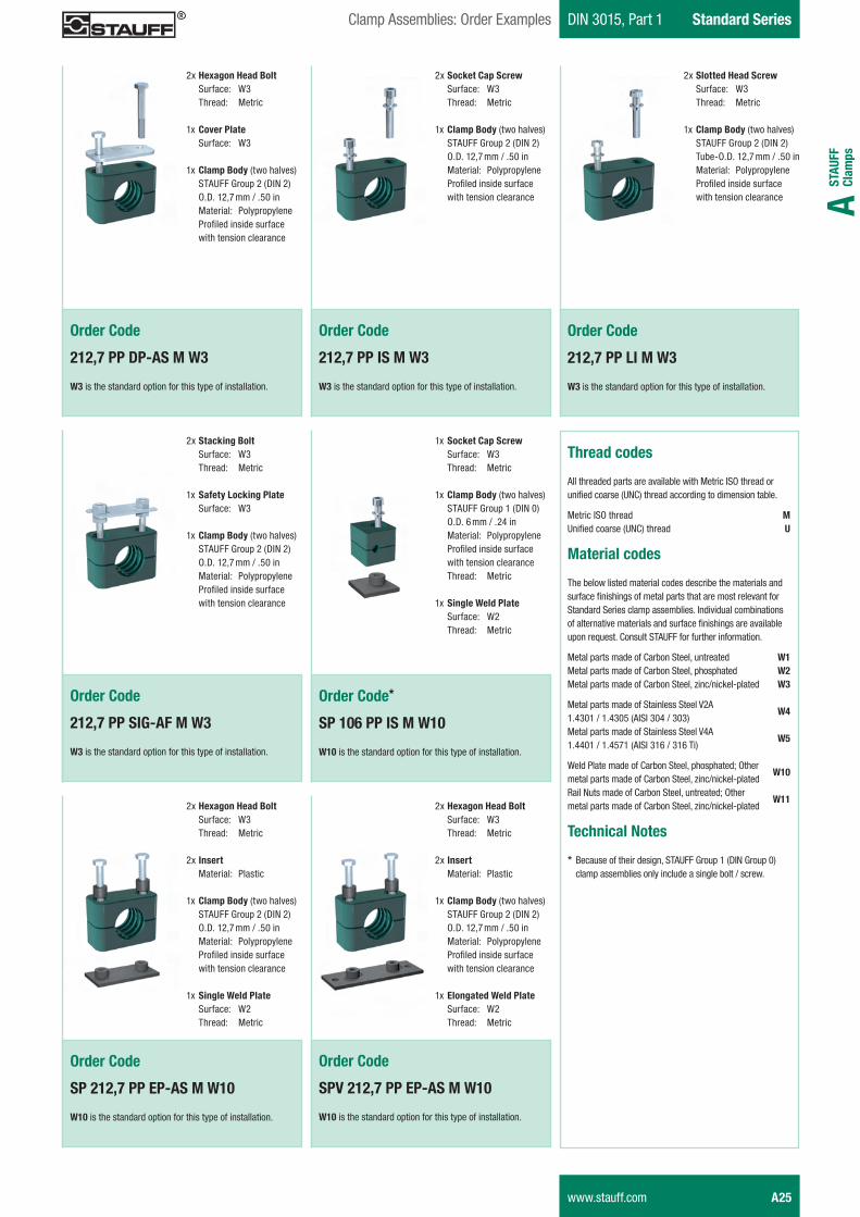
212,7 PP DP-AS M W3
W3 is the standard option for this type of installation.
2x Hexagon Head Bolt Surface: W3 Thread: Metric
1x Cover Plate Surface: W3
1x Clamp Body (two halves) STAUFF Group 2 (DIN 2) O.D. 12,7 mm / .50 in Material: Polypropylene Profiled inside surface with tension clearance
Order Code
212,7 PP IS M W3
W3 is the standard option for this type of installation.
2x Socket Cap Screw Surface: W3 Thread: Metric
1x Clamp Body (two halves) STAUFF Group 2 (DIN 2) O.D. 12,7 mm / .50 in Material: Polypropylene Profiled inside surface with tension clearance
Order Code
212,7 PP LI M W3
W3 is the standard option for this type of installation.
2x Slotted Head Screw Surface: W3 Thread: Metric
1x Clamp Body (two halves) STAUFF Group 2 (DIN 2) Tube-O.D. 12,7 mm / .50 in Material: Polypropylene Profiled inside surface with tension clearance
Thread codes
All threaded parts are available with Metric ISO thread orunified coarse (UNC) thread according to dimension table.
Metric ISO thread MUnified coarse (UNC) thread U
Material codes
The below listed material codes describe the materials and surface finishings of metal parts that are most relevant for Standard Series clamp assemblies. Individual combinations of alternative materials and surface finishings are available upon request. Consult STAUFF for further information.
Metal parts made of Carbon Steel, untreated W1Metal parts made of Carbon Steel, phosphated W2Metal parts made of Carbon Steel, zinc/nickel-plated W3
Metal parts made of Stainless Steel V2A 1.4301 / 1.4305 (AISI 304 / 303)
W4
Metal parts made of Stainless Steel V4A1.4401 / 1.4571 (AISI 316 / 316 Ti)
W5
Weld Plate made of Carbon Steel, phosphated; Othermetal parts made of Carbon Steel, zinc/nickel-plated
W10
Rail Nuts made of Carbon Steel, untreated; Othermetal parts made of Carbon Steel, zinc/nickel-plated
W11
Technical Notes
* Because of their design, STAUFF Group 1 (DIN Group 0) clamp assemblies only include a single bolt / screw.
Order Code
212,7 PP SIG-AF M W3
W3 is the standard option for this type of installation.
2x Stacking Bolt Surface: W3 Thread: Metric
1x Safety Locking Plate Surface: W3
1x Clamp Body (two halves) STAUFF Group 2 (DIN 2) O.D. 12,7 mm / .50 in Material: Polypropylene Profiled inside surface with tension clearance
Order Code*
SP 106 PP IS M W10
W10 is the standard option for this type of installation.
1x Socket Cap Screw Surface: W3 Thread: Metric
1x Clamp Body (two halves) STAUFF Group 1 (DIN 0) O.D. 6 mm / .24 in Material: Polypropylene Profiled inside surface with tension clearance Thread: Metric
1x Single Weld Plate Surface: W2 Thread: Metric
Order Code
SP 212,7 PP EP-AS M W10
W10 is the standard option for this type of installation.
2x Hexagon Head Bolt Surface: W3 Thread: Metric
2x Insert Material: Plastic
1x Clamp Body (two halves) STAUFF Group 2 (DIN 2) O.D. 12,7 mm / .50 in Material: Polypropylene Profiled inside surface with tension clearance
1x Single Weld Plate Surface: W2 Thread: Metric
Order Code
SPV 212,7 PP EP-AS M W10
W10 is the standard option for this type of installation.
2x Hexagon Head Bolt Surface: W3 Thread: Metric
2x Insert Material: Plastic
1x Clamp Body (two halves) STAUFF Group 2 (DIN 2) O.D. 12,7 mm / .50 in Material: Polypropylene Profiled inside surface with tension clearance
1x Elongated Weld Plate Surface: W2 Thread: Metric
www.stauff.com A25
Schelle-2012-03-28-EN.indd 25 29.03.2012 10:11:14
�%��%� ������7
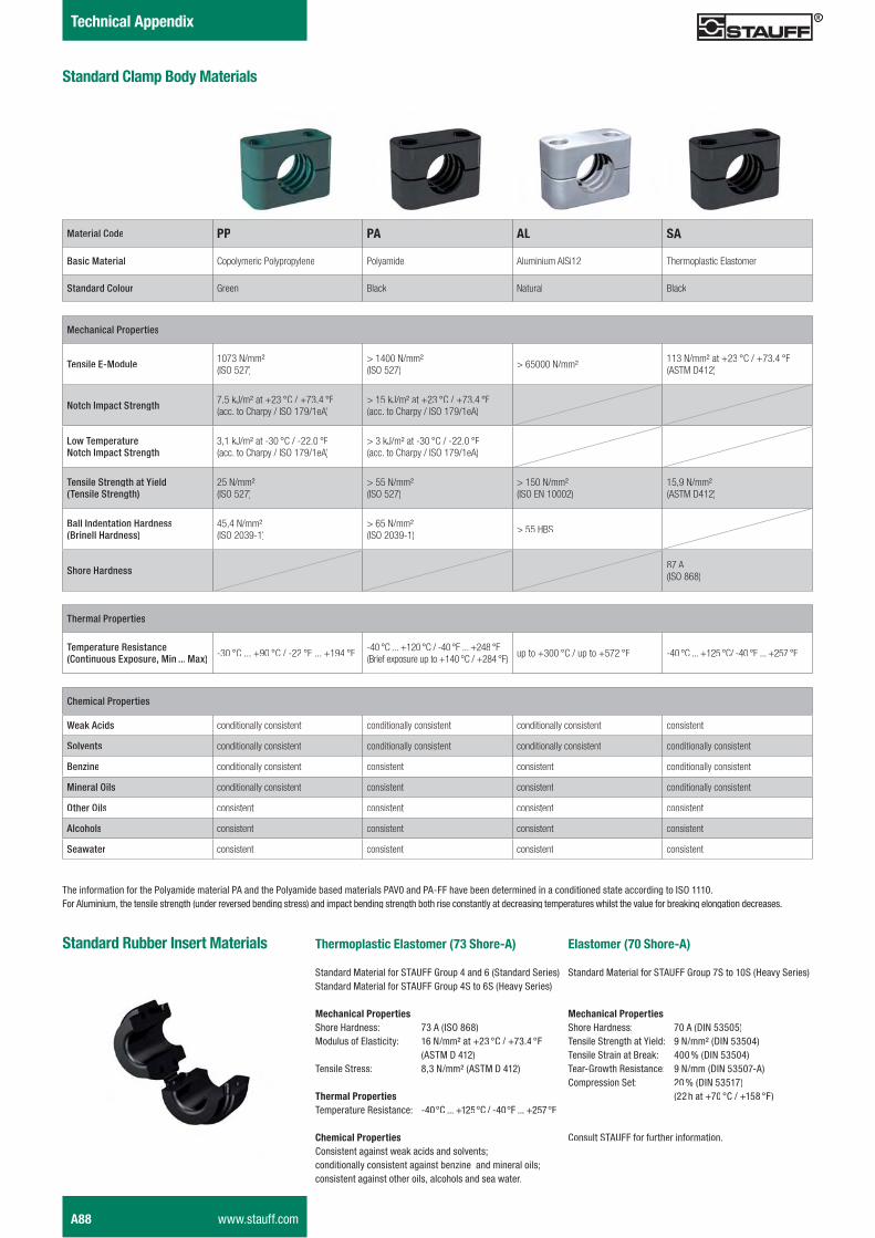
Material Code PP PA �X SA
Basic Material Copolymeric Polypropylene Polyamide Aluminium AlSi12 Thermoplastic Elastomer
Standard Colour Green Black Natural Black
Mechanical Properties
Tensile E-Module 1073 N/mm² (ISO 527)
> 1400 N/mm²(ISO 527)
> 65000 N/mm² 113 N/mm² at +23 °C / +73.4 °F(ASTM D412)
Notch Impact Strength 7,5 kJ/m² at +23 °C / +73.4 °F(acc. to Charpy / ISO 179/1eA)
> 15 kJ/m² at +23 °C / +73.4 °F(acc. to Charpy / ISO 179/1eA)
Low TemperatureNotch Impact Strength
3,1 kJ/m² at -30 °C / -22.0 °F(acc. to Charpy / ISO 179/1eA)
> 3 kJ/m² at -30 °C / -22.0 °F(acc. to Charpy / ISO 179/1eA)
Tensile Strength at Yield(Tensile Strength)
25 N/mm²(ISO 527)
> 55 N/mm²(ISO 527)
> 150 N/mm² (ISO EN 10002)
15,9 N/mm² (ASTM D412)
Ball Indentation Hardness(Brinell Hardness)
45,4 N/mm² (ISO 2039-1)
> 65 N/mm² (ISO 2039-1)
> 55 HBS
Shore Hardness 87 A(ISO 868)
���������� ���������$���� �
Thermal Properties
Temperature Resistance (Continuous Exposure, Min ... Max) -30 °C ... +90 °C / -22 °F ... +194 °F -40°C ... +120°C / -40°F ... +248°F
(Brief exposure up to +140°C / +284°F)up to +300 °C / up to +572 °F -40°C ... +125°C/ -40°F ... +257°F
Chemical Properties
Weak Acids conditionally consistent conditionally consistent conditionally consistent consistent
Solvents conditionally consistent conditionally consistent conditionally consistent conditionally consistent
Benzine conditionally consistent consistent consistent conditionally consistent
Mineral Oils conditionally consistent consistent consistent conditionally consistent
Other Oils consistent consistent consistent consistent
Alcohols consistent consistent consistent consistent
Seawater consistent consistent consistent consistent
The information for the Polyamide material PA and the Polyamide based materials PAV0 and PA-FF have been determined in a conditioned state according to ISO 1110.For Aluminium, the tensile strength (under reversed bending stress) and impact bending strength both rise constantly at decreasing temperatures whilst the value for breaking elongation decreases.
������ ���%�& ��������=>�����,�!
Standard Material for STAUFF Group 4 and 6 (Standard Series)Standard Material for STAUFF Group 4S to 6S (Heavy Series)
$%���%� ��������Shore Hardness: 73 A (ISO 868)Modulus of Elasticity: 16 N/mm² at +23 °C / +73.4 °F
(ASTM D 412)Tensile Stress: 8,3 N/mm² (ASTM D 412)
����� ��������Temperature Resistance: -40°C ... +125°C / -40°F ... +257°F
���%� ��������Consistent against weak acids and solvents;conditionally consistent against benzine and mineral oils;consistent against other oils, alcohols and sea water.
���������������������$���� � & ��������=2�����,�!
Standard Material for STAUFF Group 7S to 10S (Heavy Series)
$%���%� ��������Shore Hardness: 70 A (DIN 53505)Tensile Strength at Yield: 9 N/mm² (DIN 53504)Tensile Strain at Break: 400 % (DIN 53504)Tear-Growth Resistance: 9 N/mm (DIN 53507-A)Compression Set: 20 % (DIN 53517)
(22 h at +70 °C / +158 °F)
Consult STAUFF for further information.
A88 www.stauff.com
STAU
FF
Clam
psA
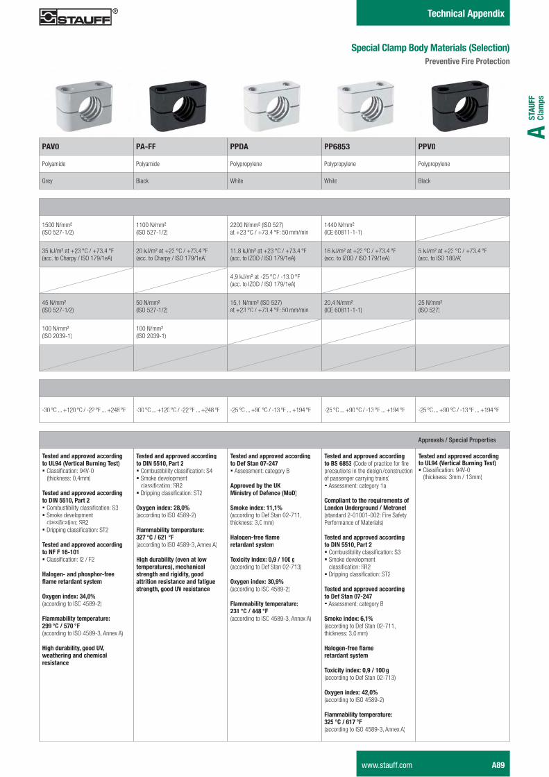
Approvals / Special Properties
��������������-���%%����)����DX@���.��%� ������)����!� ������������������������������� ������
��������������-���%%����)����(�I�##;2H������?� ����!�����"��������������#� Smoke development����������������$%� &���� ��������������'%
��������������-���%%����)����I'�'�;",;2;� ������������*%�:�;%
+� �)�,�������������,5��_�����������������
�7�)����7`�>�H2b(according to ISO 4589-2)
' ����� �����������`?@@ c��:�#=2 c'(according to ISO 4589-3, Annex A)
+)������� ��H�)����D.H������)�����%��%� �������%
��������������-���%%����)����(�I�##;2H������?������!�����"���������������� Smoke development ����������������$%��&���� ��������������'%
�7�)����7`�?VH2b(according to ISO 4589-2)
' ����� �����������`>?= c��:�"?; c'(according to ISO 4589-3, Annex A)
+)������� ����-����� �����������!H��%���%� ����)��������)���H�)�����������������%�����5��)�����)��H�)����D. ������%
��������������-���%%����)���(5������2=,?�=� <��������������� ��"�=
�����-��������D/�$�������5�(5�%��$�(!
���E���7`�;;H;b(according to Def Stan 02-711,����������#�� ���
+� �)�,5��_����������������
��7%�����7`�2H@�:�;22 )(according to Def Stan 02-713)
�7�)����7`�>2H@b�(according to ISO 4589-2)
' ����� �����������`�?>; c��:���V c'(according to ISO 4589-3, Annex A)
��������������-���%%����)�to BS 6853 �������?���������?������precautions in the design / construction of passenger carrying trains)� <��������������� ��"�@�
���� �����������e��������5X������D���)������:�$���������������%��@��@���%��;�����?��"Performance of Materials)
��������������-���%%����)����(�I�##;2H������?� ����!�����"��������������#� Smoke development����������������$%� &���� ��������������'%
��������������-���%%����)����(5������2=,?�=� <��������������� ��"�=
���E���7`�"H;b(according to Def Stan 02-711, ����������#�� ���
+� �)�,5��_����������������
��7%�����7`�2H@�:�;22 )(according to Def Stan 02-713)
�7�)����7`��?H2b(according to ISO 4589-2)
' ����� �����������`>?# c��:�";= c'(according to ISO 4589-3, Annex A)
��������������-���%%����)����DX@���.��%� ������)����!��������������������������������� #���:�@#���
� �%��%� ������7
��.2 ��,'' PPDA PP6853 ��.2
Polyamide Polyamide Polypropylene Polypropylene Polypropylene
Grey Black White White Black
1500 N/mm²(ISO 527-1/2)
1100 N/mm² (ISO 527-1/2)
2200 N/mm² (ISO 527)���K%# X��:�KY#[� X;��\� ��:��
1440 N/mm²(ICE 60811-1-1)
35 kJ/m² at +23 °C / +73.4 °F(acc. to Charpy / ISO 179/1eA)
20 kJ/m² at +23 °C / +73.4 °F(acc. to Charpy / ISO 179/1eA)
11,8 kJ/m² at +23 °C / +73.4 °F(acc. to IZOD / ISO 179/1eA)
16 kJ/m² at +23 °C / +73.4 °F(acc. to IZOD / ISO 179/1eA)
5 kJ/m² at +23 °C / +73.4 °F(acc. to ISO 180/A)
4,9 kJ/m² at -25 °C / -13.0 °F(acc. to IZOD / ISO 179/1eA)
45 N/mm²(ISO 527-1/2)
50 N/mm²(ISO 527-1/2)
15,1 N/mm² (ISO 527) ���K%# X��:�KY#[� X;��\� ��:��
20,4 N/mm² (ICE 60811-1-1)
25 N/mm²(ISO 527)
100 N/mm² (ISO 2039-1)
100 N/mm² (ISO 2039-1)
-30°C ... +120°C / -22°F ... +248°F -30°C ... +120°C / -22°F ... +248°F -25°C ... +90°C / -13°F ... +194°F -25°C ... +90°C / -13°F ... +194°F -25°C ... +90°C / -13°F ... +194°F
��%� �� ���������$���� ���� %���!��-��-�'������%����
www.stauff.com A89
�%��%� ������7
���������� ���������(�)��
���] ��(�)����] ����������5�%������������ ����%
Available in the Standard, Heavy, Twin and Heavy Twin Series� Recommended for the safe installation of rigid pipes or tubes� Available for all commonly used outside diameters and
nominal sizes� Vibration/noise reducing and impact absorbing effect towards
the direction of the line provided by the grooves on the insideof the clamp bodies
����+��������!���������������5�%��:��������� ����%
� Available in the Standard, Heavy and Twin Series� Recommended for the safe installation of hoses or cables� Available for all commonly used outside diameters and
nominal sizes� Smooth inside surface and chamfered edges avoid
damaging of the hose or cable
� ���������������`�����������������!���Q��'������ ���sliding (see page A91 for Maximum Loads in Pipe Direction)
� Clearance between the clamp halves provides tension of the tube or pipe
� To be used as guide allowing the line to slide� Choose internal diameter of the clamp body slightly smaller
than the outside diameter of the hose or cable to use it as�`�����������������!���Q��'������ ���������Q
�����������������������!
� Available in the Standard, Heavy and Heavy Twin Series� Recommended for the extra-gentle installation of pipes,
tubes, hoses or cables� Available for all commonly used outside diameters and
nominal sizes� Rubber insert made of Thermoplastic Elastomer with a
hardness of 73 Shore-A provides most effective reductionof vibration and noise caused by vibration
�-� �(�)�
� Available in the Standard and Heavy Series� Recommended for the safe installation of electric cables
with diameters between 20 mm (.79 in) and 72 mm (2.83 in)
�%���)� ���(�)��������./
� Available in the Standard Series (STAUFF Group 5)� Recommended for the safe installation of proximity switches
according to DIN EN 60947-5-2 or similar, rectangularconstruction, with a square of 40mm x 40mm (1.57in x 1.57in)or 40 mm x 36 mm (1.57 in x 1.42 in)
A90 www.stauff.com
STAU
FF
Clam
psA
� �%��%� ������7
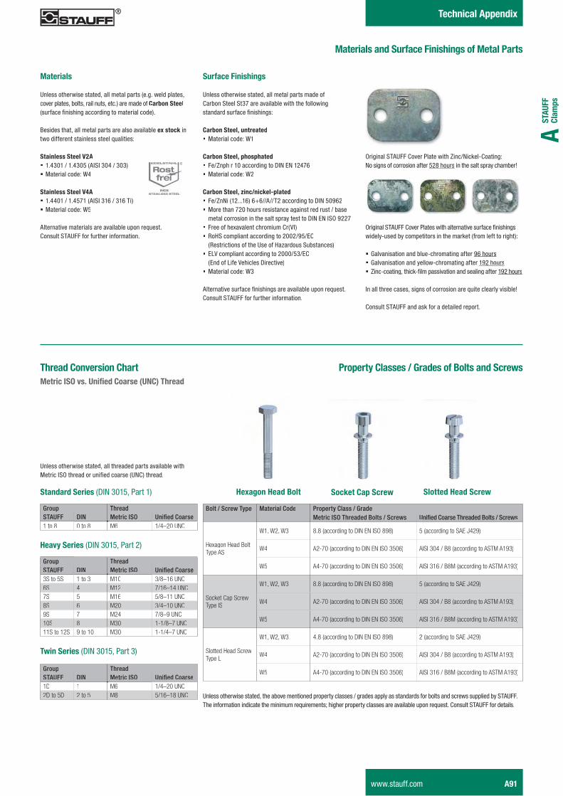
$���� ���������5�%�'����)���5�$�� ������
$���� �
Unless otherwise stated, all metal parts (e.g. weld plates,cover plates, bolts, rail nuts, etc.) are made of ��������� ;��� �������'�Q��������Q�����������������>#
Besides that, all metal parts are also available 7����%E inEtwo different stainless steel qualities:
���� ����� �.?�� 1.4301 / 1.4305 (AISI 304 / 303)� Material code: W4
���� ����� �.���� 1.4401 / 1.4571 (AISI 316 / 316 Ti)� Material code: W5
Alternative materials are available upon request.Consult STAUFF for further information.
���5�%�'����)�
Unless otherwise stated, all metal parts made of Carbon Steel St37 are available with the following ����������� �������'�Q�{
��������� H��������� Material code: W1
��������� H����������� Fe/Znph r 10 according to DIN EN 12476� Material code: W2
��������� H�Z�%:�%E ,� ���� Fe/ZnNi (12...16) 6+6//A//T2 according to DIN 50962� More than 720 hours resistance against red rust / base
metal corrosion in the salt spray test to DIN EN ISO 9227� Free of hexavalent chromium Cr(VI) � RoHS compliant according to 2002/95/EC
(Restrictions of the Use of Hazardous Substances)� ELV compliant according to 2000/53/EC
(End of Life Vehicles Directive)� Material code: W3
��������!����� �������'�Q�������!��������������X����#Consult STAUFF for further information.
Original STAUFF Cover Plate with Zinc/Nickel-Coating:No signs of corrosion after 528 hours in the salt spray chamber!
J��Q�����������=�!���&������?��'���������!����� �������'�Q��widely-used by competitors in the market (from left to right):
� Galvanisation and blue-chromating after 96 hours� Galvanisation and yellow-chromating after 192 hours� |��*�����Q���'��}*���������!�������������Q�� ����192 hours
In all three cases, signs of corrosion are quite clearly visible!
Consult STAUFF and ask for a detailed report.
��������� �����:�K������5��� ��������%���
Bolt / Screw Type Material Code Property Class / GradeMetric ISO Threaded Bolts / Screws ����� �����������������������������
Hexagon Head BoltType AS
W1, W2, W3 8.8 (according to DIN EN ISO 898) 5 (according to SAE J429)
W4 A2-70 (according to DIN EN ISO 3506) AISI 304 / B8 (according to ASTM A193)
W5 A4-70 (according to DIN EN ISO 3506) AISI 316 / B8M (according to ASTM A193)
Socket Cap ScrewType IS
W1, W2, W3 8.8 (according to DIN EN ISO 898) 5 (according to SAE J429)
W4 A2-70 (according to DIN EN ISO 3506) AISI 304 / B8 (according to ASTM A193)
W5 A4-70 (according to DIN EN ISO 3506) AISI 316 / B8M (according to ASTM A193)
Slotted Head ScrewType LI
W1, W2, W3 4.8 (according to DIN EN ISO 898) 2 (according to SAE J429)
W4 A2-70 (according to DIN EN ISO 3506) AISI 304 / B8 (according to ASTM A193)
W5 A4-70 (according to DIN EN ISO 3506) AISI 316 / B8M (according to ASTM A193)
Unless otherwise stated, the above mentioned property classes / grades apply as standards for bolts and screws supplied by STAUFF.The information indicate the minimum requirements; higher property classes are available upon request. Consult STAUFF for details.
���������-�����������$��%�����-�<�D�]���������DI�!������
Group ThreadSTAUFF DIN Metric ISO ����� �����1 to 8 0 to 8 M6 1/4–20 UNC
�������������(DIN 3015, Part 1)
+�-������(DIN 3015, Part 2)
Group ThreadSTAUFF DIN Metric ISO ����� �����3S to 5S 1 to 3 M10 3/8–16 UNC6S 4 M12 7/16–14 UNC7S 5 M16 5/8–11 UNC8S 6 M20 3/4–10 UNC9S 7 M24 7/8–9 UNC10S 8 M30 1-1/8–7 UNC11S to 12S 9 to 10 M30 1-1/4–7 UNC
��������(DIN 3015, Part 3)
Group ThreadSTAUFF DIN Metric ISO ����� �����1D 1 M6 1/4–20 UNC2D to 5D 2 to 5 M8 5/16–18 UNC
Unless otherwise stated, all threaded parts available with@�������J��'���������������������;�<=>��'����#
+7�)���+����� � � �����+����%����%E�������%��
www.stauff.com A91
�%��%� ������7
Outside Diameter Distance A(mm) (in) (m) (ft)
114,0 ... 168,0 4.50 ... 6.60 5,00 16,40
168,0 ... 219,0 6.60 ... 8.60 6,00 19,68
219,0 ... 324,0 8.60 ... 12.70 6,70 21,98
324,0 ... 356,0 12.70 ... 14.00 7,00 22,96
356,0 ... 406,0 14.00 ... 16.00 7,50 24,60
406,0 ... 419,0 16.00 ... 16.50 8,20 26,90
419,0 ... 508,0 16.50 ... 20.00 8,50 27,88
508,0 ... 521,0 20.00 ... 20.50 9,00 29,52
521,0 ... 558,0 20.50 ... 22.00 10,00 32,80
558,0 ... 800,0 22.00 ... 31.50 12,50 41,00
Outside Diameter Distance A(mm) (in) (m) (ft)
6,0 ... 12,7 .23 ... .50 1,00 3,28
12,7 ... 22,0 .50 ... .86 1,20 3,94
22,0 ... 32,0 .86 ... 1.25 1,50 4,92
32,0 ... 38,0 1.25 ... 1.50 2,00 6,56
38,0 ... 57,0 1.5 ... 2.25 2,70 8,86
57,0 ... 75,0 2.25 ... 2.95 3,00 9,84
75,0 ... 76,1 2.95 ... 3.00 3,50 11,48
76,1 ... 88,9 3.00 ... 3.50 3,70 12,14
88,9 ... 102,0 3.50 ... 4.00 4,00 13,12
102,0 ... 114,0 4.00 ... 4.50 4,50 14,76
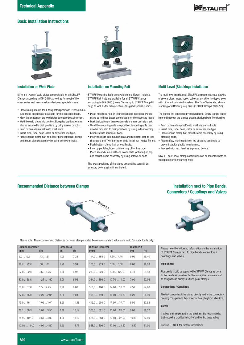
�%�������(����%������� ����
���%������ �����������%����
����� ��������L ��� ��
Different types of weld plates are available for all STAUFF Clamps according to DIN 3015 as well as for most of theother series and many custom-designed special clamps.
� Place weld plates in their designated positions. Please make sure these positions are suitable for the expected loads.
� Mark the locations of the weld plates to ensure best alignment.� Weld the weld plates into position. Elongated weld plates can
also be mounted to their positions by using screws or bolts.� Push bottom clamp half onto weld plate.� Insert pipe, tube, hose, cable or any other line type.� Place second clamp half and cover plate (optional) on top
and mount clamp assembly by using screws or bolts.
����� ��������$�����)���
STAUFF Mounting Rails are available in different heights.STAUFF Rail Nuts are available for all STAUFF Clampsaccording to DIN 3015 (Heavy Series up to STAUFF Group 6Sonly) as well as for many custom-designed special clamps.
� Place mounting rails in their designated positions. Pleasemake sure these bases are suitable for the expected loads.
� Mark the locations of the mounting rails to ensure best alignment.� Weld the mounting rails into position. Mounting rails can
also be mounted to their positions by using side-mounting brackets with screws or bolts.
� Insert rail nuts into mounting rail and turn until stop to lock (Standard and Twin Series) or slide in rail nut (Heavy Series).
� Push bottom clamp half onto rail nuts.� Insert pipe, tube, hose, cable or any other line type.� Place second clamp half and cover plate (optional) on top
and mount clamp assembly by using screws or bolts.
The exact positions of the clamp assemblies can still be��~�������� �������Q�����"�������#
$� �,X- �����%E�)!������ ����
The multi-level installation of STAUFF Clamps permits easy stackingof several pipes, tubes, hoses, cables or any other line types, evenwith different outside diameters. The Twin Series also allows stacking of different group sizes (STAUFF Groups 2D to 5D).
The clamps are connected by stacking bolts. Safety locking plates inserted between the clamps prevent stacking bolts from turning.
� Push bottom clamp half onto weld plate or rail nuts.� Insert pipe, tube, hose, cable or any other line type. � Place second clamp half mount clamp assembly by using
stacking bolts.� Place safety locking plate on top of clamp assembly to
prevent stacking bolts from turning.� Proceed with next level as explained before.
STAUFF multi-level clamp assemblies can be mounted both toweld plates or to mounting rails.
statted below are standard values and valid for static loads only.Please note: The recommended distances between clamps s
Please note the following information on the installation of STAUFF Clamps next to pipe bends, connectors / couplings and valves:
�������
Pipe bends should be supported by STAUFF Clamps as close to the bends as possible. Furthermore, it is recommended to design these clamps as fixed point clamps.
����%�����:����� �)�
The first clamp should be placed directly next to the connector / coupling. This protects the connector / coupling from vibrations.
.� -�
If valves are incorporated in the pipelines, it is recommended that support is provided in front of and behind these valves.
Consult STAUFF for further information.
����� ������7������������H�����%�����:����� �)������.� -�
Distance A
A92 www.stauff.com
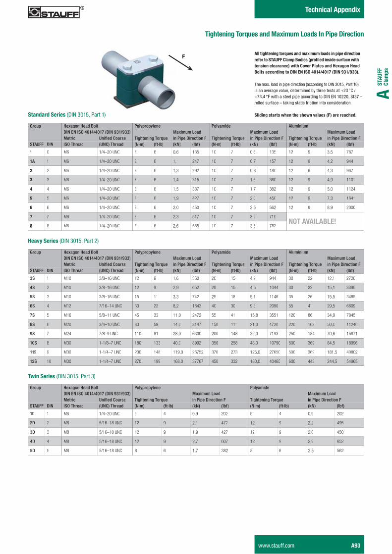
STAU
FF
Clam
psA
� �%��%� ������7
�)����)����e�������$�7����X�����������(�%���
Group Hexagon Head Bolt Polypropylene Polyamide AluminiumDIN EN ISO 4014/4017 (DIN 931/933) Maximum Load Maximum Load Maximum LoadMetric ����� ����� Tightening Torque in Pipe Direction F Tightening Torque in Pipe Direction F Tightening Torque in Pipe Direction F
STAUFF DIN ISO Thread (UNC) Thread (N·m) (ft·lb) (kN) (lbf) (N·m) (ft·lb) (kN) (lbf) (N·m) (ft·lb) (kN) (lbf)
1 0 M6 1/4–20 UNC 8 6 0,6 135 10 7 0,6 135 12 9 3,5 787
1A 1 M6 1/4–20 UNC 8 6 1,1 247 10 7 0,7 157 12 9 4,2 944
2 2 M6 1/4–20 UNC 8 6 1,3 292 10 7 0,8 180 12 9 4,3 967
3 3 M6 1/4–20 UNC 8 6 1,4 315 10 7 1,6 360 12 9 4,9 1101
4 4 M6 1/4–20 UNC 8 6 1,5 337 10 7 1,7 382 12 9 5,0 1124
5 5 M6 1/4–20 UNC 8 6 1,9 427 10 7 2,0 450 12 9 7,3 1641
6 6 M6 1/4–20 UNC 8 6 2,0 450 10 7 2,5 562 12 9 8,9 2000
7 7 M6 1/4–20 UNC 8 6 2,3 517 10 7 3,2 719I����.��X��X&f
8 8 M6 1/4–20 UNC 8 6 2,6 585 10 7 3,5 787
� ��)����)����e���������7���� ������������%�����5��������D''�� �������������] ���������5�%����������% ����%!�������-��� ��������+7�)���+����� ����%%����)����(�I�&I������2;�:�2;=��(�I�@>;:@>>!<
The max. load in pipe direction (according to DIN 3015, Part 10)is an average value, determined by three tests at +23 °C / +73.4 °F with a steel pipe according to DIN EN 10220, St37 –rolled surface – taking static friction into consideration.
� ��)���������������������-� ����'!������%��<������������ (DIN 3015, Part 1)
Group Hexagon Head Bolt Polypropylene Polyamide AluminiumDIN EN ISO 4014/4017 (DIN 931/933) Maximum Load Maximum Load Maximum LoadMetric ����� ����� Tightening Torque in Pipe Direction F Tightening Torque in Pipe Direction F Tightening Torque in Pipe Direction F
STAUFF DIN ISO Thread (UNC) Thread (N·m) (ft·lb) (kN) (lbf) (N·m) (ft·lb) (kN) (lbf) (N·m) (ft·lb) (kN) (lbf)
3S 1 M10 3/8–16 UNC 12 9 1,6 360 20 15 4,2 944 30 22 12,1 2720
4S 2 M10 3/8–16 UNC 12 9 2,9 652 20 15 4,5 1044 30 22 15,1 3395
5S 3 M10 3/8–16 UNC 15 11 3,3 742 25 18 5,1 1146 35 26 15,5 3485
6S 4 M12 7/16–14 UNC 30 22 8,2 1843 40 30 9,3 2090 55 41 29,5 6609
7S 5 M16 5/8–11 UNC 45 33 11,0 2472 55 41 15,8 3551 120 86 34,9 7845
8S 6 M20 3/4–10 UNC 80 59 14,0 3147 150 111 21,0 4720 220 162 50,0 11240
9S 7 M24 7/8–9 UNC 110 81 28,0 6300 200 148 32,0 7193 250 184 70,6 15871
10S 8 M30 1-1/8–7 UNC 180 133 40,0 8992 350 258 48,0 10790 500 369 84,5 18996
11S 9 M30 1-1/4–7 UNC 200 148 119,0 26752 370 273 125,0 27650 500 369 181,5 40802
12S 10 M30 1-1/4–7 UNC 270 199 168,0 37767 450 332 180,0 40465 600 443 244,5 54965
+�-����� (DIN 3015, Part 2)
Group Hexagon Head Bolt Polypropylene PolyamideDIN EN ISO 4014/4017 (DIN 931/933) Maximum Load Maximum LoadMetric ����� ����� Tightening Torque in Pipe Direction F Tightening Torque in Pipe Direction F
STAUFF DIN ISO Thread (UNC) Thread (N·m) (ft·lb) (kN) (lbf) (N·m) (ft·lb) (kN) (lbf)
1D 1 M6 1/4–20 UNC 5 4 0,9 202 5 4 0,9 202
2D 2 M8 5/16–18 UNC 12 9 2,1 472 12 9 2,2 495
3D 3 M8 5/16–18 UNC 12 9 1,9 427 12 9 2,0 450
4D 4 M8 5/16–18 UNC 12 9 2,7 607 12 9 2,9 652
5D 5 M8 5/16–18 UNC 8 6 1,7 382 8 6 2,5 562
������� (DIN 3015, Part 3)
F
www.stauff.com A93
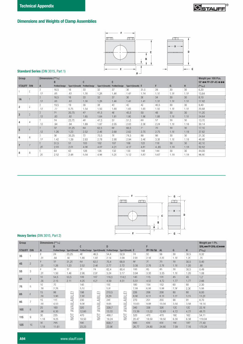
�%��%� ������7
Group Dimensions (mm/in) Weight per 100 Pcs.B C D SP �� PP-DP-AS� ����
STAUFF DIN A Profiled Design Type H (Smooth) Profiled Design Type H (Smooth) Profiled Design Type H (Smooth) E F G H (kg/lbs)
1 03 16,5 16 33 32 37 36 31,5 28 30 30 6,20.12 .65 .63 1.30 1.26 1.46 1.42 1.24 1.10 1.18 1.18 13,64
1A 13 16,5 16 33 32 37 36 36 34 30 30 8,10.12 .65 .63 1.30 1.26 1.46 1.42 1.41 1.33 1.18 1.18 17.82
2 23 19,5 19 39 38 43 42 42 40,5 30 30 9,40.12 .77 0.75 1.54 1.50 1.69 1.65 1.65 1.59 1.18 1.18 20.68
3 33 21 20,75 42 41,5 46 45,5 50 48 30 30 11,20.12 .83 .82 1.65 1.64 1.81 1.80 1.96 1.88 1.18 1.18 24.64
4 43 24 23,75 48 47,5 52 51,5 60 57 30 30 13,70.12 .94 .94 1.89 1.87 2.05 2.03 2.36 2.24 1.18 1.18 30.14
5 53 32 31,25 64 62,5 68 66,5 71 70 30 30 17,10.12 1.26 1.23 2.52 2.46 2.68 2.62 2.79 2.75 1.18 1.18 37.62
6 63 36 35,25 72 70,5 76 74,5 88 86 30 30 21,30.12 1.42 1.39 2.83 2.78 2.99 2.94 3.46 3.38 1.18 1.18 46.86
7 75 51,5 51 103 102 107 106 122 118 30 30 42,10.20 2.03 2.01 4.06 4.02 4.21 4.17 4.81 4.,65 1.18 1.18 92.62
8 85 64 63 128 126 132 130 148 144 30 30 44,00.20 2.52 2.48 5.04 4.96 5.20 5.12 5.83 5.67 1.18 1.18 96.80
������������ (DIN 3015, Part 1)
F
C
B
AE
+�-������(DIN 3015, Part 2)
F
C
B
A
E
G
DH
G
Group Dimensions (mm/in) Weight per 1 Pc.B C D F SPAL �� PP-DPAL-AS � ����
STAUFF DIN A Profiled Design Type H (Smooth) Profiled Design Type H (Smooth) Profiled Design Type H (Smooth) E PP / PA / SA AL G H (kg/lbs)
3S 18 24 23,25 48 46,5 54,4 52,9 74 55 56 30 30,5 0,32.31 .94 .92 1.89 1.83 2.14 2.09 2.91 2.16 2.20 1.18 1.20 .70
4S 28 32 31,25 64 62,5 70,4 68,9 86 70 70 30 30,5 0,40.31 1.26 1.23 2.52 2.46 2.77 2.72 3.39 2.76 2.76 1.18 1.20 .88
5S 38 38 37 76 74 82,4 80,4 100 85 85 30 30,5 0,49.31 1.50 1.46 2.99 2.91 3.24 3.17 3.94 3.35 3.35 1.18 1.20 1.08
6S 410 54,5 53,5 109 107 116,5 114,5 140 115 120 45 45 1,21.39 2.15 2.11 4.29 4.21 4.59 4.51 5.51 4.53 4.72 1.77 1,77 2.66
7S 510 70
I���
�.��
X��X
&f
140
I���
�.��
X��X
&f
150
I���
�.��
X��X
&f
180 154 152 60 60 2,30.39 2.76 5.51 5.91 7.09 6.06 5.98 2.36 2,36 5.06
8S 615 99 198 210,5 226 206 208 80 80 6,00.59 3.90 7.80 8.29 8.90 8.11 8.19 3.15 3.15 13.20
9S 715 115 230 245 270 251 255 90 91 8,70.59 4.53 9.06 9.65 10.63 9.88 10.04 3.54 3.58 19.14
10S 825 160 320 338,7 340 336 326 120 120 22,16.98 6.30 12.60 13.33 13.39 13.22 12.83 4.72 4.72 48.75
11S 930 235 470 488,7 520 470 470 160 162 54,111.18 9.25 18.50 19.24 20.47 18.50 18.50 6.30 6.38 119.04
12S 1030 295 590 608,7 680 630 630 180 182 77,401.18 11.61 23.23 23.96 26.77 24.80 24.80 7.09 7.16 170.28
D
G
H
(�����������L)�����5�� ��������� �
A94 www.stauff.com
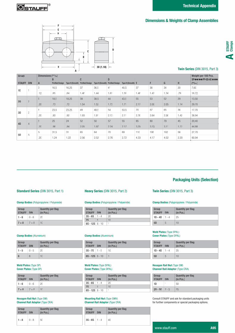
STAU
FF
Clam
psA
� �%��%� ������7
Dimensions (mm/in) Weight per 100 Pcs.B C D SP ��/����// PP-GD-AS � ����
STAUFF DIN A ������������� Type H (Smooth) ������������� Type H (Smooth) ������������� Type H (Smooth) E F G H (kg/lbs)
1D 13 16,5 16,25 37 36,5 41 40,5 37 36 34 20 7,60
.12 .65 .64 1.46 1.44 1.61 1.59 1.46 1.42 1.34 .79 16.72
2D 25 18,5 18,25 39 38,5 44 43,5 55 53 52 29 13,50
.20 .73 .72 1.54 1.52 1.73 1.71 2.17 2.09 2.05 1.14 29.70
3D 35 23,5 23,25 49 48,5 54 53,5 70 67 65 36 17,70
.20 .93 .92 1.93 1.91 2.13 2.11 2.76 2.64 2.56 1.42 38.94
4D 45 25 24 52 50 57 55 85 80 79 45 20,40
.20 .98 .94 2.05 1.97 2.24 2.17 3.35 3.15 3.11 1.77 44.88
5D 55 31,5 31 65 64 70 69 110 106 102 56 27,70
.20 1.24 1.22 2.56 2.52 2.76 2.72 4.33 4.17 4.02 2.20 60.94
F
C
B
AE
GH
D
>2��;<;V!��������(DIN 3015, Part 3)
(�������[�L)�����5�� ��������� �
��%E�)�)�D������ %���!
��������(DIN 3015, Part 3)+�-������(DIN 3015, Part 2)�������������(DIN 3015, Part 1)
Group Quantity per BagSTAUFF DIN (in Pcs.)
1 - 6 0 - 6 25
7 + 8 7 + 8 10
� �������� (Polypropylene / Polyamide)
L ��� ����(Type SP)��-��� ��� (Type DP)
+7�)����� �I�� (Type SM) ����� ��� �������� (Type CRA)
Group Quantity per BagSTAUFF DIN (in Pcs.)3S - 6S 1 - 4 207S 5 108S - 12S 6 - 10 1
� �������� (Aluminium)
Group Quantity per BagSTAUFF DIN (in Pcs.)
1 - 6 0 - 6 25
7 + 8 7 + 8 10
Group Quantity per BagSTAUFF DIN (in Pcs.)
1 - 8 0 - 8 50
� �������� (Polypropylene / Polyamide)
Group Quantity per BagSTAUFF DIN (in Pcs.)
3S - 7S 1 - 5 10
8S - 12S 6 - 10 1
L ��� ��� (Type SPAL) ��-��� ��� (Type DPAL)
Group Quantity per BagSTAUFF DIN (in Pcs.)3S - 6S 1 - 4 207S 5 108S - 12S 6 - 10 1
$�����)��� �I���(Type GMV) ����� ��� �������� (Type CRA)
Group Quantity per BagSTAUFF DIN (in Pcs.)
3S - 6S 1 - 4 40
Group Quantity per BagSTAUFF DIN (in Pcs.)
1D - 4D 1 - 4 25
5D 5 10
� �������� (Polypropylene / Polyamide)
L ��� ��� (Type SPAL) ��-��� ��� (Type DPAL)
+7�)����� �I���(Type SM) ����� ��� �������� (Type CRA)
Group Quantity per BagSTAUFF DIN (in Pcs.)
1 - 5 0 - 5 25
6 6 10
� �������� (Aluminium)
Group Quantity per BagSTAUFF DIN (in Pcs.)
1D - 4D 1 - 4 25
5D 5 10
Group Quantity per BagSTAUFF DIN (in Pcs.)
1D 1 50
2D - 5D 2 - 5 25
Consult STAUFF and ask for standard packaging unitsfor further components or special packaging options.
www.stauff.com A95