CL Series “e” Thermal Transfer Printers Library...SECTION 1. PRINTER OVERVIEW INTRODUCTION The...
103
PN 9001074 Rev. B CL Series “e” Thermal Transfer Printers Operator Manual for CL408e, CL412e, CL608e & CL612e
Transcript of CL Series “e” Thermal Transfer Printers Library...SECTION 1. PRINTER OVERVIEW INTRODUCTION The...

PN 9001074 Rev. B
CL Series “e”Thermal Transfer Printers
Operator Manualfor
CL408e, CL412e, CL608e &CL612e

SATO CL Series “e” Printers 08/31/03 PN 9001074 Rev. B
SATO America, Inc.10350A Nations Ford Road
Charlotte, NC 28273
Main Phone: (704) 644-1650Fax: (704) 644-1662
Tech Support Hotline: (704) 644-1660Tech Support Fax: (704) 644-1661
Email: [email protected]
www.satoamerica.com
© Copyright 2003SATO America, Inc.
Warning: This equipment complies with the requirements in Part 15 of FCC rules fora Class A computing device. Operation of this equipment in a residential area maycause unacceptable interference to radio and TV reception requiring the operator totake whatever steps are necessary to correct the interference.
All rights reserved. No part of this document may be reproduced or issued to thirdparties in any form whatsoever without the express permission of SATO America, Inc.The materials in this document is provided for general information and is subject tochange without notice. SATO America, Inc. assumes no responibilities for any errorsthat may appear.

WARNING
CL408e AND CL412e PRINTERS ARE SHIPPED WITH EITHER A110-VOLT OR 220-VOLT POWER SUPPLY
AS A CUSTOMER SPECIFIED OPTION.
BEFORE CONNECTING A PRINTER TO ANY POWER SOURCE, ENSURE IT WAS FACTORY CONFIGURED
FOR THE APPROPRIATE VOLTAGE.
THE VOLTAGE FOR THE PRINTER DELIVERED MAY BE FOUND ON THE SHIPPING CONTAINER.
CONTACT SATO AMERICA, INC. OR OUR
AUTHORIZED RESELLER SHOULD A DISCREPANCY EXIST.

PREFACE
CL SERIES “e” PRINTER OPERATOR’S MANUAL
The CL Series “e” Printer Operator’s Manual contains basic information about theprinter such as setup, installation, cleaning and maintenance. It also containscomplete instructions on how to use the operator panel to configure the printer. Thefollowing is a brief description of each section in this manual.
SECTION 1. PRINTER OVERVIEW
This section contains a discussion of the printer specifications and optionalfeatures.
SECTION 2. INSTALLATION
This section contains instructions on how to unpack and set up the printer,AND load the labels and ribbon.
SECTION 3. CONFIGURATION
This section contains instructions on how to use the operator panel toconfigure the printer.
SECTION 4. CLEANING AND MAINTENANCE
This section contains instructions on how to clean and maintain the printer.
SECTION 5. PROGRAMMING
This section has been replaced by the “e” and PRO Printer ProgrammingReference, PN 9001096 on the Printer Utilities CD-ROM. It introduces theSATO printer programming language. It contains the commands that are usedwith the printer to produce labels with bar codes, alphanumeric data andgraphics.
SECTION 6. INTERFACE SPECIFICATIONS
This section contains the printer’s interface specifications, which includedetailed information on how to properly interface your printer to the hostsystem.
SECTION 7. TROUBLESHOOTING
This section contains troubleshooting procedures to follow in the event youhave printer problems.
SATO CL “e” Series Printers PN 9001074 Rev. B Page - i

APPENDICES
APPENDIX A: Optional Features
Page - ii PN 9001074 Rev. B SATO CL “e” Series Printers
Preface

TABLE OF CONTENTS
SECTION 1. PRINTER OVERVIEW
Introduction . . . . . . . . . . . . . . . . . . . . . . . . . . . . . 1-1General Printer Specifications . . . . . . . . . . . . . . . . . . . . 1-2Character Fonts . . . . . . . . . . . . . . . . . . . . . . . . . . . 1-4Bar Codes . . . . . . . . . . . . . . . . . . . . . . . . . . . . . . 1-5Physical . . . . . . . . . . . . . . . . . . . . . . . . . . . . . . . 1-6Optional Accessories . . . . . . . . . . . . . . . . . . . . . . . . . 1-7
SECTION 2. INSTALLATION AND CONFIGURATION
Introduction . . . . . . . . . . . . . . . . . . . . . . . . . . . . . 2-1Unpacking and Parts Identification . . . . . . . . . . . . . . . . . 2-2Setting Up the Printer . . . . . . . . . . . . . . . . . . . . . . . . 2-3Loading Labels, Tags and Ribbon in the CL608 and CL612e. . . . . 2-4Loading Labels, Tags and Ribbon in the CL408 and CL412e. . . . . 2-8Label Sensor Adjustments, CL608e and CL612e . . . . . . . . . . 2-11Label Sensor Adjustments, CL408e and CL412e . . . . . . . . . . 2-11Operator Panel, CL608e and CL612e . . . . . . . . . . . . . . . . 2-12Operator Panel,CL408e and CL412e . . . . . . . . . . . . . . . . 2-14Rear Panel, CL608e and CL612e . . . . . . . . . . . . . . . . . . 2-16Rear Panel, CL408e and CL412e . . . . . . . . . . . . . . . . . . 2-17Switches and Sensors, CL608e and CL612e . . . . . . . . . . . . 2-18Switches and Sensors, CL408e and CL412e . . . . . . . . . . . . 2-19
SECTION 3. CONFIGURATION
Printer DIP Switch Configuration . . . . . . . . . . . . . . . . . . 3-1Default Settings . . . . . . . . . . . . . . . . . . . . . . . . . . . 3-6Potentiometer Adjustments . . . . . . . . . . . . . . . . . . . . . 3-7LCD Panel Printer Configuration. . . . . . . . . . . . . . . . . . . 3-9
Normal Mode . . . . . . . . . . . . . . . . . . . . . . . . . . 3-10Advanced Mode . . . . . . . . . . . . . . . . . . . . . . . . . 3-12Card Mode . . . . . . . . . . . . . . . . . . . . . . . . . . . 3-15Service Mode . . . . . . . . . . . . . . . . . . . . . . . . . . 3-18Counter Mode. . . . . . . . . . . . . . . . . . . . . . . . . . 3-22Test Print Mode . . . . . . . . . . . . . . . . . . . . . . . . . 3-22Default Setting mode . . . . . . . . . . . . . . . . . . . . . . 3-23Clear Non-Standard Protocol Codes. . . . . . . . . . . . . . . 3-24
SATO CL “e” Series Printers PN 9001074 Rev. B Page - iii
Preface

Download User Defined Protocol Codes . . . . . . . . . . . . 3-24Hex Dump Mode . . . . . . . . . . . . . . . . . . . . . . . . 3-25
SECTION 4. CLEANING AND MAINTENANCE
Introduction . . . . . . . . . . . . . . . . . . . . . . . . . . . . . 4-1Procedures . . . . . . . . . . . . . . . . . . . . . . . . . . . . . . 4-1
Adjusting the Print Quality . . . . . . . . . . . . . . . . . . . . 4-1Darkness . . . . . . . . . . . . . . . . . . . . . . . . . . . 4-1Print Speed . . . . . . . . . . . . . . . . . . . . . . . . . . 4-2
Cleaning the Print Head, Platen and Rollers, CL608e and CL612e. . 4-2Replacing the Print Head, CL608e and CL612e . . . . . . . . . . . 4-4Cleaning the Sensors, CL608e and CL612e . . . . . . . . . . . . . 4-5Replacing the Fuse, CL608e and CL612e . . . . . . . . . . . . . . 4-6Cleaning the Print Head and Platen, CL408e and CL412e . . . . . . 4-7Replacing the Print Head, CL408e and CL412e . . . . . . . . . . . 4-8Cleaning the Sensors, CL408e and CL412e . . . . . . . . . . . . . 4-9Replacing the Fuse, CL408e and CL412e . . . . . . . . . . . . . . 4-9
Procedures, CL408e and CL412e. . . . . . . . . . . . . . . . . . . 4-7
SECTION 5. PROGRAMMING
For programming information, see the “e” and PRO Printer ProgrammingReference, PN 9001096 on the Printer Utilities CD-ROM.
SECTION 6. INTERFACE SPECIFICATIONS
Introduction . . . . . . . . . . . . . . . . . . . . . . . . . . . . . 6-1Interface Types. . . . . . . . . . . . . . . . . . . . . . . . . . . . 6-1The Receive Buffer . . . . . . . . . . . . . . . . . . . . . . . . . . 6-2IEEE1284 Parallel Interface . . . . . . . . . . . . . . . . . . . . . 6-3
Electrical Specifications . . . . . . . . . . . . . . . . . . . . . 6-3Data Streams . . . . . . . . . . . . . . . . . . . . . . . . . . . 6-4Interface Pin Assignments . . . . . . . . . . . . . . . . . . . . 6-4
RS232C Serial Interface . . . . . . . . . . . . . . . . . . . . . . . 6-5General Specifications . . . . . . . . . . . . . . . . . . . . . . 6-5Electrical Specifications . . . . . . . . . . . . . . . . . . . . . 6-5Pin Assignments . . . . . . . . . . . . . . . . . . . . . . . . . 6-5Ready/Busy Flow Control . . . . . . . . . . . . . . . . . . . . 6-6X-On/X-Off Flow Control . . . . . . . . . . . . . . . . . . . . . 6-7
Universal Serial Bus (USB) Interface. . . . . . . . . . . . . . . . . 6-7Local Area Network (LAN) Interface . . . . . . . . . . . . . . . . . 6-8
Page - iv PN 9001074 Rev. B SATO CL “e” Series Printers
Preface
Bi-Directional Communications . . . . . . . . . . . . . . . . . . . 6-8ENQ/ACK/NAK. . . . . . . . . . . . . . . . . . . . . . . . . . 6-9Status Response. . . . . . . . . . . . . . . . . . . . . . . . . 6-12
Accessory (EXT) Connector. . . . . . . . . . . . . . . . . . . . . 6-18Pin Assignments. . . . . . . . . . . . . . . . . . . . . . . . . 6-18Standard Operation . . . . . . . . . . . . . . . . . . . . . . . 6-19Repeat Print. . . . . . . . . . . . . . . . . . . . . . . . . . . 6-20Error Signals . . . . . . . . . . . . . . . . . . . . . . . . . . 6-20
SECTION 6. TROUBLESHOOTING
Initial Checklist . . . . . . . . . . . . . . . . . . . . . . . . . . . 7-1Using the IEEE1284 Parallel Interface . . . . . . . . . . . . . . . . 7-1Using the RS232C Serial Interface . . . . . . . . . . . . . . . . . . 7-3Error Signals . . . . . . . . . . . . . . . . . . . . . . . . . . . . . 7-4
APPENDICES
APPENDIX A: Optional AccessoriesLabel Rewinder, All Models . . . . . . . . . . . . . . . . . . . A-1Label Cutter, All Models . . . . . . . . . . . . . . . . . . . . . A-2Label Dispense Option . . . . . . . . . . . . . . . . . . . . . . A-3
CL608e and CL612e . . . . . . . . . . . . . . . . . . . . . A-3CL408e and CL412e . . . . . . . . . . . . . . . . . . . . . A-4
Memory Cards, All Models . . . . . . . . . . . . . . . . . . . . A-7CL608e and CL612e . . . . . . . . . . . . . . . . . . . . . A-7CL408e and CL412e . . . . . . . . . . . . . . . . . . . . . A-8
Interface Cards, All Models . . . . . . . . . . . . . . . . . . . A-10Calendar, All Models . . . . . . . . . . . . . . . . . . . . . . A-10
SATO CL “e” Series Printers PN 9001074 Rev. B Page - v
Preface

This page left intentionally blank.
Page - vi PN 9001044 Rev. B SATO CL “e” Series Printers
Preface

SECTION 1.PRINTER OVERVIEW
INTRODUCTION
The SATO CL Series “e” Thermal Transfer Printers are complete, high-performanceon-site labeling systems. All printer parameters are user programmable using thefront panel controls and the DIP switches. All popular bar codes and 14human-readable fonts, including a vector font, are resident in memory providingliterally thousands of type styles and sizes.
The Operator’s Manual will help you understand the basic operations of the printersuch as setup, installation, configuration, cleaning and maintenance.
The major differences in the CL408e and the CL412e printers is the resolution of thehead. The CL408e with its 203 dpi head provides an economical labeling solution formost applications. It can print labels up to four inches wide. If a wider label isneeded, the CL608e can print labels up to six inches wide at the same resolution. TheCL412e provides a higher print resolution, 305 dpi, to give laser-quality printing. It isuseful when higher resolution is needed for detailed graphic images. The six inchwide companion printer to the CL412e is the CL612e.
All of the CL Series “e” printers use the same command codes. The only differencesare the allowable values representing the print positions on the label. These valuesare specified in “dots” and will vary depending upon the resolution of the printer andthe amount of memory available for imaging the label. The allowable range for eachprinter is specified in a table for those command codes.
This commonalty makes it very easy to convert labels from one CL printer to anotherwithout having to create an entirely different command stream. There are somecaveats that must be observed though to compensate for the different resolution printheads. The effect of the different printer resolutions are best illustrated by taking alabel designed for a 203 dpi printer and sending the command stream to the its 305dpi counterpart. The label printed will be an exact two-thirds scale, including thefonts, bar code dimensions and line lengths/widths. The only exception is the PostNetbar code which has only one legal size and the printer resolution is automaticallycompensated for by the printer. Conversely, a label designed for a 305 dpi printer andsent to its 203 dpi cousin will be one-third larger. It probably will be “truncated” ifthe label size is larger than the maximum allowable for the printer.
The following general information is presented in this section:
• General Printer Specifications
• Optional Accessories
SATO CL Series “e” Printers PN 9001074 Rev. B Page 1-1

GENERAL PRINTER SPECIFICATIONS
Page 1-2 PN 9001074 Rev. B SATO CL Series “e” Printers
Section 1. Printer Overview
SPECIFICATION CL408e CL412e CL608e CL612e
Method Direct or Thermal Transfer
Speed (User Selectable) 2 to 6 ips50 to 150 mm/s
4 to 8 ips100 to 200 mm/s
Print Module (Dot Size) .0049 in..125 mm
.0033 in.
.083 mm.0049 in..125 mm
.0033 in.
.083 mm
Resolution 203 dpi8 dpmm
305 dpi12 dpmm
203 dpi8 dpmm
305 dpi12 dpmm
Maximum Print Width 4.1 in.104 mm
6.0 in.152 mm
6.5 in.164mm
Maximum Print Length 49.2 in.1249 mm
32.8 in.833 mm
49.2 in.1249 mm
32.8 in.833 mm
MEDIA
Minimum Width .87 in. (22 mm) 1.96 in. (50 mm)
Minimum Length .24 in. (6 mm) .78 in. (20 mm)
Maximum Width 5.1 in. (131 mm) 7 in. (178 mm)
Type Die Cut Labels, Fan-Fold, Tag Stock or Continuous
Caliper .010 in. (.25 mm)
Roll OD (max) 8.6 in. (218 mm), Face-In Wind
Core ID (min) 1.5 in. (38 mm)
Core ID (Recommended) 3 in. (76 mm)
SENSING
Transmissive See-thru Movable
Reflective Eye-Mark Movable Fixed
Continuous Form Sensor not used
RIBBON
Maximum Width 4.4 in. (111 mm) 6.75 in. (172 mm)
Length 1475 ft. (450 m) 1345 ft (410 m)
Thickness 4.5 micron, Face-In Wind
All specifications subject to change without notice.

SATO CL Series “e” Printers PN 9001074 Rev. B Page 1-3
Section 1. Printer Overview
SPECIFICATION CL408e CL412e CL608e CL612e
CONTROLS AND SIGNALS
On-Line LED Status = Green(1) Green
Power LED None Green
Media Out LED Status = Red(1) Red
Ribbon Out LED Status = Red(1) Red
Error LED Status = Red(1) Red
LCD Panel 2 Line x 16 Character
On/Off-Line Switch Front Panel
Label Feed Switch Front Panel
Power On/Off Switch Rear Panel
POTENTIOMETER ADJUSTMENTS
Print Darkness Front Panel
Pitch Front Panel
Offset Front Panel
Display None Front Panel
INTERFACE MODULES
Parallel IEEE1284 Parallel
Serial RS232C (9600 to 57,600 bps)RS422/485 (9600 to 57,600 bps)
Serial Protocol Hardware Flow Control (Ready/Busy)Software Flow Control (X-On/X-Off)
Bi-directional Status
Universal Serial Bus USB Version 1.1
Ethernet 10/100BaseT
Data Transmission ASCII Format
PROCESSING
CPU 32 Bit RISC
Flash ROM 2 MB
SDRAM 16 MB
Receive Buffer 2.95 MB
Optional Flash ROM 4 MB
Optional PCMCIA Memory 16 MB Flash or 4 MB SRAM
(1) Single two color (Red, Green) LED.
All specifications subject to change without notice.

CHARACTER FONTS
Page 1-4 PN 9001074 Rev. B SATO CL Series “e” Printers
Section 1. Printer Overview
SPECIFICATION CL408e CL608e CL412e CL612e
MATRIX FONTS
U Font (5 dots W x 9 dots H)
S Font (8 dots W x 15 dots H)
M Font (13 dots W x 20 dots H)
XU Font (5 dots W x 9 dots H) Helvetica
XS Font (17 dots Wx 17 dots H) Univers Condensed Bold
XM Font (24 dots W x 24 dots H) Univers Condensed Bold
OA Font (15 dots W x 22 dots H) OCR-A (22 dots W x 33 dots H) OCR A
OB Font 20 dots W x 24 dots H) OCR-B (30 dots W x 36 dots H) OCR B
AUTO SMOOTHING FONTS
WB WB Font (18 dots W x 30 dots H)
WL WL Font (28 dot W x 52 dots H)
XB XB Font (48 dots W x 48 dots H) Univers Condensed Bold
XL XL Font (48 dot W x 48 dots H) Sans Serif
VECTOR FONT
Proportional or Fixed SpacingFont Size 50 x 50 dots to 999 x 999 dots
Helvetica, 10 Font Variations
AGFA® RASTER FONTS
A Font CG Times, 2 to 99 pt
B Font CG Triumvirate, 2 to 99 pt
DOWNLOADABLE FONTS
Bit Mapped TrueType Fonts with Utility Program
CHARACTER CONTROL
Expansion up to 12X in either the X or Y coordinatesCharacter Pitch control
Line Space controlJournal Print facility
0°, 90°, 180° and 270° Rotation
All specifications subject to change without notice.

BAR CODES
SATO CL Series “e” Printers PN 9001074 Rev. B Page 1-5
Section 1. Printer Overview
SPECIFICATION CL408e CL608e CL412e CL612e
SYMBOLOGIES
Bookland (UPC/EAN Supplemental)EAN-8, EAN-13
CODABARCode 39Code 93Code 128
Interleaved 2 of 5Industrial 2 of 5
Matrix 2 of 5MSI
POSTNETUCC/EAN-128
UPC-A and UPC-EData MatrixMaxicodePDF417
Micro PDF417Truncated PDF417
QR Code
Ratios 1:2, 1:3, 2:5 User definable bar widths
Bar Height 4 to 600 dots, User programmable
Rotation 0°, 90°, 180° and 270°
OTHER FEATURES
Sequential Numbering Sequential numbering of both numerics and bar codes
Custom Characters RAM storage for special characters
Graphics Full dot addressable graphics, SATO Hex/Binary, .BMP or .PCXformats
Form Overlay Form overlay for high-speed editing of complex formats.
All specifications subject to change without notice.

PHYSICAL
Page 1-6 PN 9001074 Rev. B SATO CL Series “e” Printers
Section 1. Printer Overview
SPECIFICATION CL408e CL412e CL608e CL612e
DIMENSIONS
Wide 10.7 in. (271 mm) 13.8 in. (352 mm)
Deep 16.9 in. (430 mm) 16.9 in. (429 mm)
High 12.6 in. (321 mm) 11.7 in. (298 mm)
WEIGHT 28.7 lbs (13 Kg) 41.9 lbs (19 Kg)
POWER REQUIREMENTS
Voltage 110 V (±10 %)
220V (±10 %)
50/60 Hz (±1%)
Power Consumption 50W Idle130W Operating
50W Idle210W Operating
ENVIRONMENTAL
Operating Temperature 41° to 104°F (5° to 40°C)
Storage Temperature -0° to 104°F (-20° to 40°C)
Operating Humidity 15-85 % RH, non-condensing
Storage Humidity Max 90% RH, non-condensing
Electrostatic Discharge 8KV
REGULATORY APPROVALS
Safety UL, CSA
RFI/EMI FCC Class A
All specifications subject to change without notice.

OPTIONAL ACCESSORIES
SATO CL Series “e” Printers PN 9001074 Rev. B Page 1-7
Section 1. Printer Overview
ACCESSORY CL408 CL412 CL608 CL612
MEMORY EXPANSION One slot for PCMCIA Memory Cards (up to 16 MB Flash or 4 MBSRAM) and/or 4MB internal Flash ROM. Can be used for Graphic Filestorage, print buffer expansion, format storage and downloadedTrueType fonts.
CALENDAR An internally mounted Date/Time clock that can be used to date/timestamp labels at the time of printing.
LABEL CUTTER Internal attachment allowing labels to be cut at specified intervals.Controlled through programming.
LABEL DISPENSER Internal attachment allowinglabels to be peeled from backingfor immediate (on demand)application. Internal backingtake-up.
Internal attachment allowinglabels to be peeled from backingfor immediate (on demand)application. Backing take-upmounted externally to rear ofprinter.
LABEL REWINDER External option rewinds labels onto a roll after they are printed.
PARALLEL INTERFACE IEEE1284 Parallel Interface Module
SERIAL INTERFACE High Speed Serial RS232 Interface Module
UNIVERSAL SERIAL I/F USB Interface Module
ETHERNET INTERFACE 10/100BaseT Interface Module
COAX/TWINAX INTERFACE Coax/Triax Interface Module. Coax I/F emulates an IBM 3287-2printer with a standard Type A BNC connector. Twinax I/F emulatesIBM 5224, 5225, 5226 or 4214 printers with auto-terminate/cable-thrucapabilities.
All specifications subject to change without notice.

This page left intentionally blank.
Page 1-8 PN 9001074 Rev. B SATO CL Series “e” Printers
Section 1. Printer Overview

SECTION 2.INSTALLATION
INTRODUCTION
This section is provided to assist you in taking the CL Series Printer from the shippingcontainer to the application environment. Where the physical differences between theprinter models are significant (such as loading paper and ribbons), separate sectionsfor each of the models are used for clarity.
The following information is provided in this section:
• Unpacking and Parts Identification
• Setting Up the Printer
• Loading Labels or Tags
• Loading the Ribbon
• Operator Panel
SATO CL Series “e” Printers PN 9001074 Rev. B Page 2-1

UNPACKING AND PARTS IDENTIFICATION
Consider the following when unpacking the printer:
• The box should stay right-side up.
• Lift the printer out of the box carefully.
• Remove the plastic covering from the printer.
• For the CL4XX printers, remove the Front Access Door from its protectivebag and attach it to the printer.
• Remove the accessory items from their protective containers.
• If the printer has been stored in a cold environment, allow it to reach roomtemperature before powering it on.
• Set the printer on a solid, flat surface. Inspect the shipping container andprinter for any signs of damage that may have occurred during shipping.
NOTE: The following illustrations are representative only. Your printer may not bepacked exactly as shown here, but the unpacking steps are similar.
Page 2-2 PN 9001074 Rev. B SATO CL Series “e” Printers
Section 2. Installation
CL4XX Packaging CL6XX Packaging

Verify that you have the following materials when unpacking:
• Printer
• Power Cord
• Extra Ribbon Core
SETTING UP THE PRINTER
Consider the following when setting up the printer:
• Locate a solid flat surface with adequate room to set the printer. Make surethere is enough room at the top and right-hand (facing the printer) side toprovide clearance for the label access door to swing open.
• The location should be near the host computer or terminal. The maximumdistance for RS232 cables is 35 feet and six feet for IEEE1284 Parallelcables. Cables can be purchased locally, and their configuration will dependupon the host system being used.
• For information on interfacing the printer to a host system, seeSection 6: Interface Specifications.
SATO CL Series “e” Printers PN 9001074 Rev. B Page 2-3
Section 2. Installation
CL Printer
Power Cable
Operator Manual Extra Ribbon Core

LOADING LABELS, TAGS AND RIBBON CL608e and CL612e
LOADING LABELS OR TAGS
1. Open the Side Access Door byswinging it up and to the left. Thehinge system automaticallydampens the movement to preventthe door from inadvertently fallingand possibly causing injury to theoperator.
2. Open the Print Head Assemblyby pushing the Head Latchtoward the rear of the printer. ThePrint Head Assembly isspring-loaded and willautomatically open as soon as theHead Latch is disengaged.
3. Push the Label Supply Guide to the outside of the printer to give the maximumlabel width.
4. Release the Label Roll Support by pulling outward at the top and swing itdown and out of the way.
5. If using roll labels (or tags), load the roll onto the Label Supply Spindle sothat the printing side of the labels faces upwards as it unwinds from the roll. Thelabels should be wound face-in. Push the roll all the way to the inside of theprinter and push the Label Supply Guide snugly against the outside of thelabel roll.
6. If using fanfold labels (or tags) set them on a flat surface behind the printer. Passthe labels (printing side up) through the slot and under the Label SupplySpindle.
7. Open the Label Hold-Down bysqueezing the green tab and therelease tab together. The LabelHold-down is spring loaded andwill open automatically when thelatch is disengaged. Feed thelabels under the Label Guide,under the Label Hold-Down,through the Print HeadAssembly and out the front ofthe printer.
8. Inspect the label routing and verifythat the path matches thatillustrated in the Label Loading
Page 2-4 PN 9001074 Rev. B SATO CL Series “e” Printers
Section 2. Installation
Head Latch
Sensor AdjustCap Screw
Label Hold-Down
Sensor AdjustTab

diagram. Set the AdjustableLabel Guide to keep the labelsagainst the inside of the printer.
9. Close the Label Hold-Down bypushing downward on the greentab until it latches closed.
NOTE: If the Label Dispenser optionhas been purchased, see Appendix A,for proper label routing instructions.
10. Adjust the Label SensorAssembly to the correct positionby loosening the Sensor AdjustCap Screw located on the front side of the Label Hold-Down and moving theSensor Adjust Tab to the correct position. After it is correctly positioned,retighten the Sensor Adjust Cap Screw.
11. If the ribbon is already loaded, close the Print Head Assembly by pushingdownward on the green tab until it latches closed.
12. If the ribbon is not loaded, see the following description for loading instructions.
SATO CL Series “e” Printers PN 9001074 Rev. By Page 2-5
Section 2. Installation
Label RollSupport
Label Roll
Label SupplyGuide
Printed Labels
Label Guide
Media Knob
Label Backing
Dispenser Routing

12. Adjust the Media Knob based on the media you have loaded. For media up to2.3 inches wide, use the “1” position, for media between 2.3 and 4.6 inches wide,use the “2” position. For media wider than 4.6 inches, use the “3” position. If youuse media narrower than 7 inches, using the wrong setting can void the printhead warranty due to the excessive pressure.
Caution: Using media narrower than the maximum print width may cause excesshead wear due to the label edge.
LOADING THE RIBBON
1. Open the Side Access Door by swinging it up and to the left. The hinge systemautomatically dampens the movement to prevent the door from inadvertentlyfalling and possibly causing injury to the operator.
2. Open the Print Head Assembly by pushing the Head Latch toward the rearof the printer. The Print Head Assembly is spring-loaded and willautomatically open as soon as the Head Latch is disengaged.
3. Locate the Extra Ribbon Core supplied with the printer. Place the core on theRibbon Rewind Spindle, pushing it all the way to the inside of the spindle.Note that the new empty core of each subsequent roll becomes the next rewind core.
4. Load the ribbon onto the Ribbon Supply Spindle, also pushing it all the wayto the inside of the spindle. The dull side of the ribbon should be facing down as ittravels through the Print Head Assembly.
5. Feed the leader portion of theribbon through the Print HeadAssembly and up to the RibbonRewind Spindle following therouting shown in the diagram.
6. Load the ribbon behind and overthe top of the Ribbon RewindSpindle and tape it to the ExtraRibbon Core. Make sure itmatches the ribbon path shown inthe diagram.
7. Manually turn the RewindSpindle to wrap the ribbon ontothe core one to two turns to secureit.
8. If the labels or tags are alreadyloaded, close the Print HeadAssembly by pushing downwardon the green tab until it latchesclosed.
NOTE: Run a test print to ensure that the labels and ribbons were loaded correctly.See the “Test Print” section on page 3-22 for instructions on how to run test prints.
Page 2-6 PN 9001074 Rev. B SATO CL Series “e” Printers
Section 2. Installation

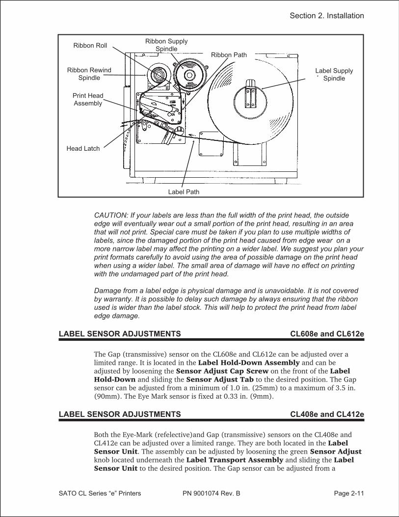
CAUTION: If your labels are less than the full width of the print head, the outsideedge will eventually wear out a small portion of the print head, resulting in an areathat will not print. Special care must be taken if you plan to use multiple widths oflabels, since the damaged portion of the print head caused from edge wear on amore narrow label may affect the printing on a wider label. We suggest you plan yourprint formats carefully to avoid using the area of possible damage on the print headwhen using a wider label. The small area of damage will have no effect on printingwith the undamaged part of the print head.
Damage from a label edge is physical damage and is unavoidable. It is not coveredby warranty. It is possible to delay such damage by always ensuring that the ribbonused is wider than the label stock. This will help to protect the print head from labeledge damage.
Section 2. Installation
SATO CL Series “e” Printers PN 9001074 Rev. B Page 2-7
Ribbon RewindSpindle
Ribbon Roll
Ribbon Path
Ribbon SupplySpindle
Print HeadAssembly
Head Latch

LOADING LABELS, TAGS AND RIBBON CL408e and CL412e
LOADING LABELS AND TAGS
1. Open the Top Access Door byswinging it up and to the left. Openthe Front Access Door by pushingdown on the green Front Cover Latchand swinging the door forward and tothe left. This gives access to the printmechanism on three sides
Note: The Top Access Door must beopen before the Front Access Doorcan be opened.
2. Open the Print Head Assembly byrotating the green Head Latchcounter clockwise. The head is springloaded and will automatically raise tothe opened position
3. Push the Label Supply Guide to theoutside of the printer to give themaximum label width.
4. Clear access is provided to the labelpath by pulling the top of the OutsideLabel Guide down.
5. If using roll labels (or tags), load theroll onto the Label Supply Spindleso that the printing side of the labelsfaces upwards as it unwinds from theroll. Push the roll all the way to theinside of the printer, raise the LabelSupply Guide and adjust its positionuntil it fits snugly against the outside ofthe label roll.
Page 2-8 PN 9001074 Rev. B SATO CL Series “e” Printers
Section 2. Installation
Front AccessDoor Latch
Top AccessDoor
Front AccessDoor
Head Latch
Feed Slot
Label
Outside Label Guide
Label SupplySpindle
Outside LabelGuide
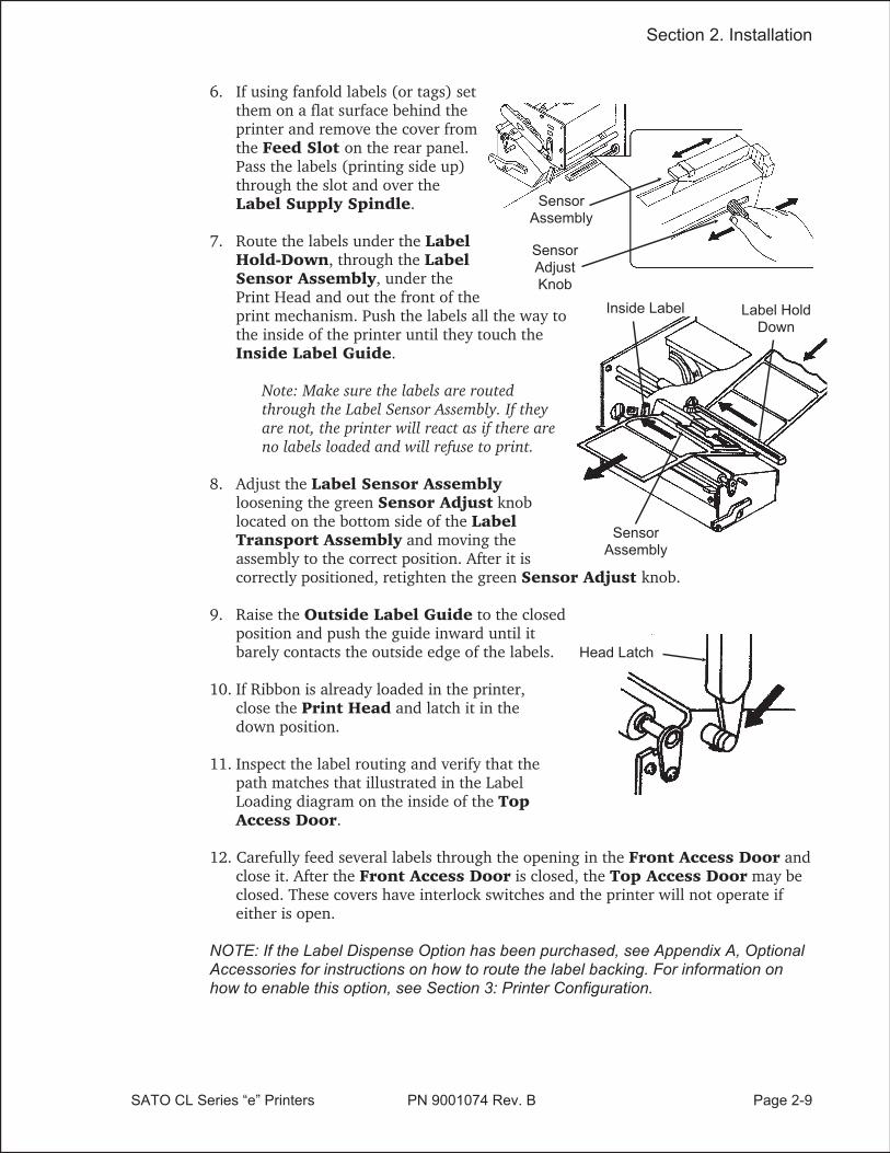
6. If using fanfold labels (or tags) setthem on a flat surface behind theprinter and remove the cover fromthe Feed Slot on the rear panel.Pass the labels (printing side up)through the slot and over theLabel Supply Spindle.
7. Route the labels under the LabelHold-Down, through the LabelSensor Assembly, under thePrint Head and out the front of theprint mechanism. Push the labels all the way tothe inside of the printer until they touch theInside Label Guide.
Note: Make sure the labels are routedthrough the Label Sensor Assembly. If theyare not, the printer will react as if there areno labels loaded and will refuse to print.
8. Adjust the Label Sensor Assemblyloosening the green Sensor Adjust knoblocated on the bottom side of the LabelTransport Assembly and moving theassembly to the correct position. After it iscorrectly positioned, retighten the green Sensor Adjust knob.
9. Raise the Outside Label Guide to the closedposition and push the guide inward until itbarely contacts the outside edge of the labels.
10. If Ribbon is already loaded in the printer,close the Print Head and latch it in thedown position.
11. Inspect the label routing and verify that thepath matches that illustrated in the LabelLoading diagram on the inside of the TopAccess Door.
12. Carefully feed several labels through the opening in the Front Access Door andclose it. After the Front Access Door is closed, the Top Access Door may beclosed. These covers have interlock switches and the printer will not operate ifeither is open.
NOTE: If the Label Dispense Option has been purchased, see Appendix A, OptionalAccessories for instructions on how to route the label backing. For information onhow to enable this option, see Section 3: Printer Configuration.
Section 2. Installation
SATO CL Series “e” Printers PN 9001074 Rev. B Page 2-9
Head Latch
Inside Label
SensorAssembly
Label HoldDown
SensorAdjustKnob
SensorAssembly

LOADING THE RIBBON
1. Open the Top and Front AccessDoors.
2. Open the Print Head Assembly byrotating the green the Head Latchcounter clockwise. The print head isspring loaded and will raise to the openposition as soon as the latch is released.
3. Locate the Extra Ribbon Coresupplied with the printer. Place the coreon the Ribbon Rewind Spindle,pushing it all the way to the inside ofthe spindle. Note that the new empty coreof each subsequent roll becomes the nextrewind core.
4. Load the ribbon onto the RibbonSupply Spindle, pushing it all theway to the inside of the spindle. Thedull side of the ribbon should be facingdown as it travels through the PrintHead Assembly.
5. Feed the leader portion of the ribbonthrough the Print Head Assemblyand up to the Ribbon RewindSpindle following the routing shownin the diagram.
6. Load the ribbon behind and over thetop of the Ribbon Rewind Spindleand tape it to the Extra RibbonCore. Make sure it matches the ribbonpath shown in the diagram.
7. Manually turn the Ribbon RewindSpindle to wrap the ribbon onto thecore one to two turns to secure it.
8. If the labels or tags are already loaded,close the Print Head Assembly byrotating the green Head Latchclockwise until it latches closed andclose the Front and Top AccessDoors.
NOTE: Run a test print to ensure that thelabels and ribbons were loaded correctly.See the “Test Print” section on page 3-22 for instructions on how to run test prints.
Page 2-10 PN 9001074 Rev. B SATO CL Series “e” Printers
Section 2. Installation
Ribbon SupplyRoll
Empty Core
Head Latch
Tape
CAUTION: If your labels are less than the full width of the print head, the outsideedge will eventually wear out a small portion of the print head, resulting in an areathat will not print. Special care must be taken if you plan to use multiple widths oflabels, since the damaged portion of the print head caused from edge wear on amore narrow label may affect the printing on a wider label. We suggest you plan yourprint formats carefully to avoid using the area of possible damage on the print headwhen using a wider label. The small area of damage will have no effect on printingwith the undamaged part of the print head.
Damage from a label edge is physical damage and is unavoidable. It is not coveredby warranty. It is possible to delay such damage by always ensuring that the ribbonused is wider than the label stock. This will help to protect the print head from labeledge damage.
LABEL SENSOR ADJUSTMENTS CL608e and CL612e
The Gap (transmissive) sensor on the CL608e and CL612e can be adjusted over alimited range. It is located in the Label Hold-Down Assembly and can beadjusted by loosening the Sensor Adjust Cap Screw on the front of the LabelHold-Down and sliding the Sensor Adjust Tab to the desired position. The Gapsensor can be adjusted from a minimum of 1.0 in. (25mm) to a maximum of 3.5 in.(90mm). The Eye Mark sensor is fixed at 0.33 in. (9mm).
LABEL SENSOR ADJUSTMENTS CL408e and CL412e
Both the Eye-Mark (refelective)and Gap (transmissive) sensors on the CL408e andCL412e can be adjusted over a limited range. They are both located in the LabelSensor Unit. The assembly can be adjusted by loosening the green Sensor Adjustknob located underneath the Label Transport Assembly and sliding the LabelSensor Unit to the desired position. The Gap sensor can be adjusted from a
Section 2. Installation
SATO CL Series “e” Printers PN 9001074 Rev. B Page 2-11
Ribbon RewindSpindle
Ribbon Roll
Ribbon Path
Print HeadAssembly
Head Latch
Label Path
Label SupplySpindle
Ribbon SupplySpindle

minimum of 0.67 in. (17mm) to a maximum of 2.5 in. (64 mm), and the Eye-Markfrom a minimum of 0.25 in. (6mm) to a maximum of 2.1 in. (53mm).
OPERATOR PANEL CL608e and CL612e
The CL608e/CL612e Operator Panel consists of five LED indicators, twomomentary contact switches, three DIP switches, four adjustment potentiometers andone LCD Display. All of these are accessible from the front of the printer. They areused to set the printer operating parameters and to indicate the status of the printerto the operator. After you power on the printer, familiarize yourself with the keys andindicators as it will help you understand the configuration process.
PRINT: Potentiometer to adjust print darkness (fine tuning).
OFFSET: Potentiometer to adjust amount of back/forward feedfor dispenser/cutter/tear-off bar position (+/-3.75 mm)
PITCH: Potentiometer to adjust home position of the label(+/- 3.75 mm). Affects stop position of label feed, printposition and dispense position.
DISPLAY: Potentiometer to adjust the contrast of the LCD.
POWER: LED, illuminated when the power is on.
Page 2-12 PN 9001074 Rev. B SATO CL Series “e” Printers
Section 2. Installation
DSW2 DSW3
LINE FEED
PITCH
OFFSET
LINE LABEL RIBBON ERRORPOWER
DISPLAY
LCDDISPLAYPANEL
Reserved

LABEL: LED, illuminated when label supply is out.
RIBBON: LED, illuminated when ribbon motion sensor does notdetect any ribbon motion.
ERROR: LED, illuminated when there is a system fault such asan open print head.
ONLINE: LED, illuminated when printer is ready to receive data.It is turned on and off by toggling the LINE key. Thisindicator will blink while the printer is receiving data.
LINE: Momentary switch. Pressing this key toggles the printerbetween the on-line and off-line mode. When theprinter is on-line, it is ready to receive data from thehost. This key acts as a pause during a print job bytaking the printer off-line. It can also be used as aPause function key to stop label during the printingprocess.
FEED: Momentary switch. Pressing this key feeds one blanklabel through the printer when it is off-line. When theprinter is on-line, another copy of the last label will beprinted (can be disabled via the LCD panel).
DSW2-3: Located behind the Front Access Door. DIP switcharray to set operational parameters of the printer.DSW1 is used to set the RS232 parameters and islocated on the RS232 interface board.
LCD: 2 Line x 16 Character LCD display. Used for settingoperational parameters of the printer.
Section 2. Installation
SATO CL Series “e” Printers PN 9001074 Rev. B Page 2-13

OPERATOR PANEL CL408e and CL412e
The CL408e/CL412e Operator Panel consists of one two-color (red and green)LED indicator, two momentary contact switches, two DIP switches (a third is locatedon the RS232 interface card), four adjustment potentiometers and one LCD Display.All of these are accessible from the front of the printer, however some are notaccessible unless the front cover is open. They are used to set the printer operatingparameters and to indicate the status of the printer to the operator. After you poweron the printer, familiarize yourself with the keys and indicators as it will help youunderstand the configuration process.
PRINT: Located behind the Front Access Door. Potentiometerto adjust print darkness (fine tuning).
OFFSET: Located behind the Front Access Door. Potentiometerto adjust amount of back/forward feed fordispenser/cutter/tear-off bar position (+/- 3.75 mm)
PITCH: Located behind the Front Access Door. Potentiometerto adjust home position of the label (+/- 3.75 mm).Affects stop position of label feed, print position anddispense position.
Page 2-14 PN 9001074 Rev. B SATO CL Series “e” Printers
Section 2. Installation
Note: DSW1 (RS232 Parameter Select) is located on the RS232 Interface Board.
DSW2 DSW3
LINE FEED
LCDDISPLAYPANEL
LABEL TAKENTHRESHOLD
ADJUST
x
xxxPITCHOFFSEPRINT
LABELTAKEN LED
OPTIONCONNECTOR
TWO-COLORSTATUS LED

STATUS: Two-color (Red, Green) LED that indicates thefollowing status conditions:
Green - Illuminated when printer is ready to receivedata. It is turned on and off by toggling the LINEkey.
Red -Illuminated when there is a system fault suchas an open print head.
LINE: Momentary switch. Pressing this key toggles the printerbetween the on-line and off-line mode. When theprinter is on-line, it is ready to receive data from thehost. This key acts as a pause during a print job bytaking the printer off-line. It can also be used as aPause function key to stop label during the printingprocess.
FEED: Momentary switch. Pressing this key feeds one blanklabel through the printer when it is off-line. When theprinter is on-line, another copy of the last label will beprinted (can be disabled via the LCD panel).
DSW2-3: Located behind the Front Access Door. DIP switcharray to set operational parameters of the printer.DSW1 is used to set the RS232 parameters and islocated on the RS232 interface board.
LCD: 2 Line x 16 Character LCD display. Used for settingoperational parameters of the printer.
LABEL TAKENTHRESHOLD:
Located behind the Front Access Door. Thispotentiometer is used to adjust the sensing level of theLabel Taken Sensor. Active only when the LabelDispense option is installed.
OPTION CONNECTOR: Located behind the Front Access Door. This connectoris used for the cutter and dispenser optionalaccessories.
LABEL TAKEN: Located behind the Front Access Door. This LED isilluminated when a label is not present in the LabelTaken Sensor. If it is not illuminated, a label has beendetected in the sensor and printing will be inhibited untilit is removed. This LED is active only when the LabelDispense option is installed. It is used to adjust theLabel Taken Sensor threshold.
SATO CL Series “e” Printers PN 9001074 Rev. B Page 2-15
Section 2. Installation

REAR PANEL CL608e and CL612e
Power On/Off Switch: Turns power On or Off.
AC Input: Input 115V 50/60 Hz connector. Use the cableprovided.
AC Fuse: Input power protection. Type 3A/250V.
Interface Slot: Slot to plug in an interface adapter. An adapter must beconnected before the printer is operational.The adaptertypes available are:
RS232C Serial I/F Module, DB-25P.IEEE1284 Parallel I/F Module, AMP 57-40360Universal Serial Bus I/F ModuleEthernet 10/100BaseT I/F Module
Memory Card Slot: Two connectors for optional PCMCIA Memory Cards.
EXT: External signal connector, AMP 57-60140.
Page 2-16 PN 9001074 Rev. B SATO CL Series “e” Printers
Section 2. Installation
PCMCIA MemoryExpansion slot
AC Power InputConnector
External AccesoryConnector
Power Switch
I/F ModuleParallel Shown
Cover PlateRemove for access to Dispenser
and Fan-Fold Slots
AC Fuse

REAR PANEL CL408e and CL412e
Power: Switch to turn power On or Off.
AC Input: Input 115V 50/60 Hz connector. Use the cableprovided.
AC Fuse: Input power protection. Type 3A/250V.
Interface Slot: Slot to plug in an interface adapter. An adapter must beconnected before the printer is operational.The adaptertypes available are:
RS232C Serial I/F Module, DB-25P.IEEE1284 Parallel I/F Module, AMP 57-40360Universal Serial Bus I/F ModuleEthernet 10/100BaseT I/F Module
Memory Card Slot: Two slots for optional PCMCIA Memory Cards.
EXT: External signal connector for Accessories, AMP57-60140.
SATO CL Series “e” Printers PN 9001074 Rev. B Page 2-17
Section 2. Installation
PCMCIA MemoryExpansion slot
AC Power InputConnector
External AccesoryConnector
Power Switch
I/F ModuleParallel Shown
Cover PlateRemove for access to
Fan-Fold Slots
AC Fuse

SWITCHES AND SENSORS CL608e and CL612e
Ribbon End Sensor: This sensor is a motion detector that signals the printerwhen the ribbon supply is turning.
Head Open Switch: When the print head is opened, this switch is activatedand the printer will stop printing.
Label Sensor Unit: This sensor unit contains two types of sensors, one forlabel gap and one for Eye-Mark sensing.
Page 2-18 PN 9001074 Rev. B SATO CL Series “e” Printers
Section 2. Installation
RibbonMotionSensor
Label SensorUnit
CL608 and CL612 Label Sensor Positioning
0.33" (9 mm) Eye-Mark Sensor
1.0" (25 mm) to 3.5" (90 mm)Label Gap Sensor
Min. Inter-Label Gap0.12" (3 mm)
BackingPaper Inside
Edge
Label Inside Edge
LabelFeed
Direction
Miminum Eye-Mark Size.12 in (3 mm) W x .24 in. (6 mm) L

SWITCHES AND SENSORS CL408e and CL412e
Ribbon End Sensor: This sensor is a motion detector that signals the printerwhen the ribbon supply is turning.
Head Open Switch: When the print head is opened, this switch is activatedand the printer will stop printing.
Label Sensor Unit: This sensor unit contains two types of sensors, one forlabel gap and one for Eye-Mark sensing. The sensorsare adjustable over a limited range.
Front Access DoorInterlock:
This switch prevents printer operation when the FrontAccess Door is open. The Top Access Door must beopen before the Front Access Door can be opened orclosed.
SATO CL Series “e” Printers PN 9001074 Rev. B Page 2-19
Section 2. Installation
Front AccessDoor Interlock
Switch
RibbonMotionSensor
CL408 and CL412 Label Sensor Positioning
0.25" to 2.1" (6 mm to 53mm)Eye-Mark Sensor
0.67" to 2.5" (17mm to 64mm)Label Gap Sensor
MinimumInter-Label Gap
0.12" (3 mm)
BackingPaper Inside
Edge
Label Inside Edge
LabelFeed
DirectionInside Label Guide
Miminum Eye-Mark Size.12 in (3 mm) W x .24 in. (6 mm) L
Note: These positions are differentfrom the M84XX printers.

This page left intentionally blank.
Page 2-20 PN 9001074 Rev. B SATO CL Series “e” Printers
Section 2. Installation

SECTION 3.CONFIGURATION
PRINTER DIP SWITCH CONFIGURATION
DIP Switch Panels
There are two DIP switches (DSW2 and DSW3) located inside the cover. Theseswitches can be used to set:
• Thermal transfer or direct thermal mode
• Label sensor enable/disable
• Head check mode
• Hex dump mode
• Single Job or Multi-Job Receive buffer
• Operation mode
In addition, a third DIP switch is located on the RS232 Serial Adapter module and isused to set the RS232C transmit/receive parameters
Each switch is an eight section toggle switch. The ON position is always to the top. Toset the switches, first power the unit Off, then position the DIP switches. Finally, afterplacing the switches in the desired positions, power the printer back on. The switchsettings are read by the printer electronics during the power up sequence. They willnot become effective until the power is cycled.
RS232 Transmit/Receive Setting (located on RS232 I/F Module)
Data Bit Selection (DSW1-1). This switch sets the printer to receive either 7 or 8bit data bits for each byte transmitted.
Parity Selection (DSW1-2, DSW1-3). These switches select the type of parityused for error detection.
SATO CL Series “e” Printers PN 9001074 Rev. B Page 3-1
DSW1-1 SETTING
Off 8 data bits
On 7 data bits
1 2 3 4 5 6 7 8
ON
OFF
DSW1
DSW1-2 DSW1-3 SETTING
Off Off No Parity
Off On Even
On Off Odd
On On Not Used1 2 3 4 5 6 7 8
ON
OFF
DSW1

Stop Bit Selection (DSW1-4). Selects the number of stop bits to end each bytetransmission.
Baud Rate Selection (DSW1-5, DSW1-6). Selects the data rate (bps) for theRS232 port.
Protocol Selection (DSW1-7, DSW1-8). Selects the flow control and statusreporting protocols. See Section 6: Interface Specifications for more information.
(* Will select protocol for M-8400 if DSW2-8 is ON)
Printer Set Up
Print Mode Selection (DSW2-1). Selects between direct thermal printing onthermally sensitive paper and thermal transfer printing using a ribbon.
Sensor Type Selection (DSW2-2). Selects between the use of a label gap or areflective Eye-Mark detector.
Page 3-2 PN 9001074 Rev. B SATO CL Series “e” Printers
Section 3. Configuration
DSW1-5 DSW1-6 SETTING
Off Off 9600
Off On 19200
On Off 38400
On On 576001 2 3 4 5 6 7 8
ON
OFF
DSW1
DSW1-7 DSW1-8 SETTING
Off Off Rdy/Bsy
Off On Xon/Xoff
On Off Bi-Com 3
On On Bi-Com 4*1 2 3 4 5 6 7 8
ON
OFF
DSW1
DSW2-1 SETTING
Off Therm Xfr
On Direct Therm
1 2 3 4 5 6 7 8
ON
OFF
DSW2
DSW2-2 SETTING
Off Gap
On Eye-Mark
1 2 3 4 5 6 7 8
ON
OFF
DSW2
DSW1-4 SETTING
Off 1 Stop Bit
On 2 Stop Bits
1 2 3 4 5 6 7 8
ON
OFF
DSW1

Head Check Selection (DSW2-3). When selected, the printer will check for headelements that are electrically malfunctioning.
Hex Dump Selection (DSW2-4). Selects Hex Dump mode.
Receive Buffer Selection(DSW2-5). Selects the operating mode of the receivebuffer. See Section 6: Interface Specifications for more information.
Firmware Download (DSW2-6). Places the printer in the Firmware Downloadmode for downloading new firmware into flash ROM.
Protocol Code Selection (DSW2-7). Selects the command codes used forprotocol control. Refer to Appendix E for more information.
M8400 Emulation Mode (DSW2-8). For emulating earlier series softwarecommands. Should be used only if problems are encountered when using existingsoftware. This switch will also affect the settings selected by DSW1-7 and DSW1-8.
SATO CL Series “e” Printers PN 9001074 Rev. B Page 3-3
Section 3. Configuration
DSW2-3 SETTING
Off Disabled
On Enabled1 2 3 4 5 6 7 8
ON
OFF
DSW2
DSW2-4 SETTING
Off Disabled
On Enabled
1 2 3 4 5 6 7 8
ON
OFF
DSW2
DSW2-5 SETTING
Off Single Job
On Multi Job
1 2 3 4 5 6 7 8
ON
OFF
DSW2
DSW2-6 SETTING
Off Disabled
On Enabled
1 2 3 4 5 6 7 8
ON
OFF
DSW2
DSW2-7 SETTING
Off Standard
On Non-Std
1 2 3 4 5 6 7 8
ON
OFF
DSW2
DSW2-8 SETTING
Off Disabled
On Enabled
1 2 3 4 5 6 7 8
ON
OFF
DSW2

Backfeed Sequence (DSW3-1). Backfeed is used to correctly position the label forapplication and then retract the next label to the proper print position. This operationcan be performed immediately after a label is printed and used, or immediately priorto the printing of the next label.
Label Sensor Selection (DSW3-3). Enables or disables the Label Sensor. If theSensor is enabled, it will detect the edge of the label and position it automatically. Ifit is disabled, the positioning must be under software control using Line Feedcommands.
Back-Feed Selection (DSW3-4). When Back-Feed is enabled, the printer willposition the last printed label for dispensing and retract it before printing the nextlabel. The amount of backfeed offset is adjustable .
External Signal Interface. See Section 6: Interface Specifications for informationon the External Signals.
EXT Print Start Signal Selection (DSW3-5). Allows an external device toinitiate a label print for synchronization with the applicator. See Section 6: InterfaceSpecifications for a description of the signal level and requirements When DSW3-5 isOn, the unit is in the Continuous print mode, Backfeed is disabled and ExternalSignals are ignored.
Page 3-4 PN 9001074 Rev. B SATO CL Series “e” Printers
Section 3. Configuration
DSW3-1 DSW3-2 SETTING
Off Off Continuous
Off On Tear-Off
On Off Cutter
On On Dispenser1 2 3 4 5 6 7 8
ON
OFF
DSW3
DSW3-3 SETTING
Off Sensor Used
On Not Used
1 2 3 4 5 6 7 8
ON
OFF
DSW3
DSW3-4 SETTING
Off Enabled
On Disabled1 2 3 4 5 6 7 8
ON
OFF
DSW3
DSW3-5 SETTING
Off Enabled
On Disabled
1 2 3 4 5 6 7 8
ON
OFF
DSW3

External Signal Type Selection (DSW3-6, DSW3-7). Both the polarity andsignal type (level or pulse) of the external print synchronizing signal can be selected.See Section 6: Interface Specifications for a definition of signal types.
Repeat Print via External Signal (DSW3-8). Allows the applicator to reprintthe last label of the print job. See Section 6: Interface Specifications for a description ofthe signal requirements.
Reserved for Future Use (DSW3-2)
SATO CL Series “e” Printers PN 9001074 Rev. B Page 3-5
Section 3. Configuration
DSW3-6 DSW3-7 SETTING
Off Off Type 4
Off On Type 3
On Off Type 2
On On Type 11 2 3 4 5 6 7 8
ON
OFF
DSW3
DSW3-8 SETTING
Off Disabled
On Enabled
1 2 3 4 5 6 7 8
ON
OFF
DSW3

DEFAULT SETTINGS
SWITCH SELECTIONS
All switches are placed in the Off default position for shipping. This will result in thefollowing operating configuration:
Communications:Protocol:Sensor:Receive Buffer:Mode:Label Sensor:Backfeed:External Signals:
8 data bits, no parity, 1 Stop bit, 9600 Baud(1)
Ready/BusyGap SensorMulti JobBatch/continuousSensor UsedEnabledEnabled
(1) Only if RS232 I/F Module is installed.
SOFTWARE DEFAULT SETTINGS
The printer stores the software settings upon receipt and uses them until they areagain changed by receipt of a command containing a new setting. These settings arestored in non-volatile memory and are not affected by powering the printer off. Theprinter may be reset to use the default software settings by depressing the LINE andFEED keys simultaneously while powering the printer on. You will be asked toconfirm that you want the printer default settings by selecting either YES or NO byusing the LINE key to step the cursor to the desired setting. If you select YES andpress the FEED key, the following default configuration will be stored:
CL408e CL412e CL608e CL612e
Print Darkness 3 2
Print Speed 4 in. per sec. 6 in. per sec.
Print Reference Vertical = 0000, Horizontal = 0000
Zero Slash
Auto On Line Enabled
Once the default operation is completed, a DEFAULT COMPLETED message will bedisplayed on the LCD panel or a single beep will be heard if the printer does not havean LCD panel. The printer should be powered off while this message is beingdisplayed (or after the beep is heard. This saves the default settings in thenon-volatile memory where they will be automatically loaded the next time theprinter is powered on.
Page 3-6 PN 9001074 Rev. B SATO CL Series “e” Printers
Section 3. Configuration

POTENTIOMETER ADJUSTMENTS
PITCH
After the pitch has been set with the LCD Control Panel, it is sometimes desirable tomake minor adjustments. This can be done using the PITCH potentiometer on thefront panel. This potentiometer is set at the factory so that it has a range of +/- 3.75mm. The midpoint setting should have no effect on the pitch. Turning thepotentiometer all the way clockwise should move the print position 3.75 mm uptowards the top edge of the label. Turning it all the way counterclockwise shouldmove the print position down 3.75 mm.
1. While depressing the FEED key on the front panel, power the printer on.
2. When you hear one beep from the printer, release the FEED key and the printerwill display on the LCD panel a message asking what type of Test Label you wantto print.
3. Use the LINE key to step to the Configuration selection and press the FEED keyto accept the selection.
4. Use the LINE key to select the Test Label Size. After the size is selected, press theFEED key to accept the selection and the printer will begin to print test labelscontinuously.
4. Adjust the PITCH potentiometer on the front panel until the first print position isat the desired location on the label. If the potentiometer does not have enoughrange, then you will have to change the pitch setting using the front panel display.
5. Press the FEED key to stop the printer.
6. To exit the Test Label mode, power the printer off andthen back on.
Adjusting the PITCH potentiometer will affect the stop position of the label.
BACKFEED OFFSET
When a label is printed it must be correctly positioned for dispensing and application.The Backfeed adjustment is used to position the label so that it is fully dispensed andready for application. It may then be necessary to reposition the next label beforeprinting. The Backfeed (repositioning of the label)operation is enabled if DSW3-4 isin the Off position. If Backfeed is enabled, placing DSW3-1 is in the Off position willcause the backfeed operation to be performed immediately before each label isprinted. If DSW3-1 is in the On position, the backfeed operation is performed as soonas the dispensed label has been printed and taken from the printer.
The amount of backfeed is controlled by the OFFSET potentiometer on the DIPSwitch Panel inside the cover. When turned all the way counterclockwise, the amountof backfeed is +3.75 mm, and -3.75 mm when turned all the way counterclockwise.
1. Turn the printer on.
2. Press the LINE key to place the printer in the Off Line status.
SATO CL Series “e” Printers PN 9001074 Rev. B Page 3-7
Section 3. Configuration

3. Press the FEED key to feed out a blank label.
4. Adjust the position using the OFFSET potentiometer on the front control paneland feed another label by depressing the FEED key. Repeat this procedure untilthe label is fully released from the liner.
DISPLAY
This potentiometer is used to adjust the contrast of the LCD display for optimumviewing under various lighting conditions.
The PRINT potentiometer is used to adjust the amount of heat (i.e., power) applied tothe head for printing. It provides a continuous range of adjustment. Maximum printdarkness is obtained by turning the potentiometer all the way clockwise and amaximum counterclockwise setting will give the lightest print.
NOTE: The PRINT potentiometer adjustment will affect the darkness in all of thecommand code speed and darkness ranges.
Page 3-8 PN 9001074 Rev. B SATO CL Series “e” Printers
Section 3. Configuration

LCD PANEL PRINTER CONFIGURATION
The LCD Panel is used by the operator in conjunction with the LINE and FEEDswitches to manually enter printer configuration settings. Many of these settings canalso be controlled via software commands and in the case of conflict betweensoftware and control panel settings, the printer will always use the last valid setting.If you load a label job that includes software settings and then enter a new setting viathe LCD panel, the manually set values will be used by the printer. If you set thevalues manually and then download a job with software settings, the softwaresettings will be used.
There are nine modes of operation. To enter the desired mode, the KEY SEQUENCEcombination listed in the table below must be performed. The initial LCD displaymessage is shown for each mode.
SATO CL Series “e” Printers PN 9001074 Rev. B Page 3-9
Section 3. Configuration
MODE KEY SEQUENCE INITIAL DISPLAY PAGE
Normal POWER ONLINEQTY:000000
3-10
Advanced LINE + POWER ADVANCED MODE 3-12
Test Print FEED + POWER TEST PRINT MODECONFIGURATION
3-22
Default Setting LINE + FEED + POWER DEFAULT SETTINGYES NO
3-23
Clear Non-Standard Protocol DSW2-7 ON + LINE + FEED+ POWER
ALT. PROTOCOL 3-24
Protocol Code Download DSW2-7 ON + POWER USER DOWNLOAD 3-24
Hex Dump DSW2-4 ON + POWER ONLINEQTY:000000
3-25

NORMAL MODE
The printer initially powers on in the ONLINE mode. The user can access the UserSettings using the following procedures.
ONLINEQTY:000000
The LCD will display the ONLINE status on the top line andthe bottom line will contain the label quantity (QTY) status.The messsge will be changed to OFFLINE whenever theprinter is switched offline by pressing the LINE key. As soon aprint job is received, the quantily line will indicate the numberof labels to be printed. As soon as the label job begins to print,the display will indicate the number of labels in the print jobthat remains to be printed.
OFFLINE000000
Press the LINE key once. When the display changes toOFFLINE, press the FEED and LINE keys simultaneously formore than one second.
PRINT DARKNESS1 2 3 4 5
The LCD now displays the Print Darkness selections. Thecurrent setting is indicated by a cursor over one of the rangesettings.
1. Press the LINE key to step the cursor to the desiredsetting.
2. Once the correct setting is highlighted, press the FEEDkey to accept the selection and step the display to thenext adjustment.
PRINT SPEED4 6 8
The print speed selections are dependent upon the printermodel. The current setting is indicated by the underline cursor.
1. Use the LINE key to step the cursor to the desiredsetting.
2. Once the correct setting is highlighted, press the FEEDkey to accept the selection and step the display to thenext adjustment.
Page 3-10 PN 9001074 Rev. B SATO CL Series “e” Printers
Section 3. Configuration
CL408e/CL412e CL608e/CL612e
2 ips 4 ips
3 ips 6 ips
4 ips 8 ips
5 ips
6 ips

PITCH OFFSET+ 00mm
The label Pitch is the distance from the leading edge (theedge that comes out of the printer first) of a label and theleading edge of the next label. The leading edge position ofthe label can be adjusted relative to the print head +/- 49mmin increments of 1mm. Once the position is set, it can be fineadjusted +/- 3.75mm using the PITCH potentometer on theAdjustment Panel.
1. The cursor will initially be positioned over the PitchDirection setting. Pressing the LINE key will step thesetting to the positive (+) or negative (-) selection. Apositive selection moves the leading edge of the labelforward (away from the print head) while a negativeselection moves the leading edge of the label back intothe mechanism.
2. Once the correct direction is selected, pressing the FEEDkey will accept the setting and advance the cursor to theOffset selection.
3. Use the LINE key to step the first digit of the counter tothe desired setting. The display will increment one stepeach time the LINE key is pressed. The reading willadvance to a setting of 4 after which it will automaticallywrap and start at 0 again.
4. Press the FEED key to accept the setting and advancethe cursor to the second digit. Again use the LINE key tostep to the desired setting. Once it is correct, pressing theFEED key will step to the next adjustment.You may wish to print a test label after completing theadjustments to ensure they are correct.
SATO CL Series “e” Printers PN 9001074 Rev. B Page 3-11
Section 3. Configuration
ABCDEFG
ABCDEFG
ABCDEFG
Moved with negative(-) offset to print onleading edge of thelabel
Original (0 offset) firstline print position
Sensor
Positio
n
Moved with positive(+) offset to print ontrailing edge of label
Leading edge of thelabel as detected by

CANCEL PRINT JOBYES NO
If the printer has a print job(s) in memory, selecting YES willcause the job(s) to be cleared. The default selection is NO. Besure you want to cancel the print job(s) before selecting yes asthe job(s) cannot be recovered and will have to beretransmitted tyo the printer.
1. Use the LINE key to step the cursor to either the YES orNO selection.
2. Once the correct setting is highlighted, pressing the FEEDkey will accept the setting.
CANCEL PRINT JOBCOMPLETED
3. After the print job(s) have been cleared from memory, theprinter will display a COMPLETED message for 3 secondsand then return to the initial ONLINE Normal Mode.
4. If you wish to change any of the settings, you must enterthe User Settings mode again by taking the printerOFFLINE and pressing the LINE and FEED keys.
ADVANCED MODE
An Advanced Mode is provided to make adjustments that require only occasionalchanges. Since they affect the basic operation of the printer, the procedure forentering this mode is designed to prevent someone from accidently changing thesettings.
ADVANCED MODE The Advance Mode is entered by pressing the LINE key whilesimultaneously turning power on. The printer will emit one longbeep after which the LINE key is released. Pressing the FEEDkey will step the display to the first selection.
ZERO SLASHYES NO
This setting determines if a zero is printed with a slash orwithout a slash. This setting can also be controlled viasoftware commands. When YES is selected, the printerinternal fonts will have a slash through the center of the zerocharacter.
1. Use the LINE key to step the cusor to either the YES orNO selection.
2. Once the correct setting is highlighted, pressing the FEEDkey will accept the setting and advance the display to theAuto Online display.
AUTO ONLINEYES NO
This setting determines the mode in which the printer powersup. If the YES selection is made, the printer powers up in theONLINE mode and is ready to print. If NO is selected, theprinter powers up in the OFF LINE mode and must bemanually placed in the ON LINE mode by pressing the LINEkey before it is ready to print.
1. Use the LINE key to step the cursor to either the YES orNO selection.
2. Once the correct setting is highlighted, pressing the FEEDkey will accept the setting and advance the display to thePrint Offset display.
Page 3-12 PN 9001074 Rev. B SATO CL Series “e” Printers
Section 3. Configuration

PRINT OFFSETV:+000 H:+000
Vertical Offset is the distance down from the leading edge (theedge of the label that comes out of the printer first) to the firstvertical print position. A positive setting moves the first printposition down the length of the label while making it negativemoves it up the length of the label. Horizontal Offset isdistance that the label image is shifted either to the right or lefton the label. The image is shifted to the left (towards theinside edge of the label for a right-hand printer) for a positivesetting and it is shifted to the right (towards the outside edgeof the label) for a negative setting. This setting changes thebase reference point for all subsequent label jobs. It’s effect isidentical to the <ESC>A3 Base Reference point command.Since the printer moves the label in discrete steps equal to thesize of the print dot, the units of measure for Vertical andHorizontal Offset distance is dots. The maximum values thatcan be set for each is +/-800.
1. Use the LINE key to step the first digit of the counter tothe desired setting. The display will increment one stepeach timethe LINE key is pressed.
2. Press the FEED key to accept the setting and advancethe cursor to the second digit. Again use the LINE key tostep to the desired setting. Once it is correct, pressing theFEED key will step to the next adjustment.
3. Once the setting is correct, pressing the FEED key willaccept the setting and advance to the next display.
You may wish to print a test label after completing theadjustments to ensure they are correct.
Note: This setting can be overriden by the Base ReferencePoint Command.
SET CALENDARYES NO
The Calendar Option is ia standard feature in all Se printersallowing the date and time to be set manually using the LCDDisplay or via the <ESC>WT Calendar Set command. The lastsetting, set either manually via software command, receivedby the printer will be the value used. The format of the displayis YY/MM/DD hh:mm (Year/Month/Day/hours:minutes).Thedate format is fixed and cannot be changed.To enable the Calendar feature (if installed), press the LINEkey until the cursor is over the the YES. If the Calendarfeature is to be disabled, press the LINE key until the cursor isover the NO. When the desired setting is selected, press theFEED key.
SATO CL Series “e” Printers PN 9001074 Rev. B Page 3-13
Section 3. Configuration

CALENDAR00/00/00 00:00
1. Year - The first display shown will have the two digit yearselection underlined. You can scroll through the dates bypressing the LINE key. The year number will increase byone each time the LINE key is pressed until it reaches itsmaximum legal value (i.e., “99” for the year digits) atwhich point it will wrap around to the “00” setting.
2. Month - After you have set the correct year, pressing theFEED key will advance the cursor to the two digit Monthposition. You can scroll through the numberscorresponding to the month by pressing the LINE key. Themonth number will increase by one each time the LINEkey is pressed until it reaches a value of “12” at whichpoint it will wrap around to the “01” setting.
3. Day - After you have set the correct month, pressing theFEED key will advance the cursor to the two digit Dayposition. You can scroll through the numberscorresponding to the month date by pressing the LINEkey. The date number will increase by one each time theLINE key is pressed until it reaches a value of “31” atwhich point it will wrap around to the “01” setting.
4. Hour - After you have set the correct date, pressing theFEED key will advance the cursor to the two digit Hourposition. You can scroll through the numberscorresponding to the hour (using a 24 hour clock) bypressing the LINE key. The hour number will increase byone each time the LINE key is pressed until it reaches avalue of “24” at which point it will wrap around to the “01”setting.
5. Minute- After you have set the correct hour, pressing theFEED key will advance the cursor to the two digit Minuteposition. You can scroll through the numberscorresponding to the hour by pressing the LINE key. Theminute number will increase by one each time the line keyis pressed until it reaches a value of “60” at which point itwill wrap around to the “01” setting.
6. After you have set the minutes, pressing the FEED keywill accept the setting and advance to the Ignore CR/LFselection.
IGNORE CR/LFYES NO
This selection tells the printer to strip out all carriagereturn/line feed pairs (CRLF ) from the data stream, includinggraphics and 2D bar codes. It is used primrily to maintaincompatibility with earlier models of SATO printers.
1. Use the LINE key to step the cusor to either the YES orNO selection.
2. Once the correct setting is highlighted, pressing the FEEDkey will accept the setting and advance the display to theCharacter Pitch display.
Page 3-14 PN 9001074 Rev. B SATO CL Series “e” Printers
Section 3. Configuration

CHARACTER PITCHFIXED PROP
This selection allows you to set the default character pitch toeither fixed character spacing or proportional characterspacing.
1. Use the LINE key to step the cursor to the desired setting.
2. Once the correct setting is highlighted, pressing the FEEDkey will accept the setting and the display will return to theAdvanced Mode display.
Note: This command can be overriden by the <ESC>PR or<ESC>PS Character Pitch Commands.
ADVANCED MODE To exit the Advanced mode, power the printer off and thenback on.
CARD MODE
The Card Mode allows the operator to manage the Expanded Memory (PCMCIA Cardor Internal Expanded Flash ROM).
ADVANCED MODE The Card Mode is entered from the Advanced Mode displayby pressing the LINE key once.
CARD MODE The Card Mode display indicates that the printer is in the CardMode. To advance to the first selection, press the FEED key.
MEM SELECT (CC1)CARD MEMORY
This selection determines which type of optional expandedmemory will be addressed as “CC1" in the commandstreams.The CARD selection specifies the optional PCMCIAcard as CC1 and the optional Expanded Flash ROM as CC2.The Memory selection specifies the optional Expanded FlashROM as CC1 and the optional PCMCIA card as CC2.
1. Step the cursor to the desired selection using the LINEkey.
2. Once the cursor is positioned over the desired selection,press the FEED key to accept the selection and advancethe display.
CARD->MEMORYCOPYTRUETYPEFONT Y/N
This selection allows you to copy TrueType fonts from thePCMCIA Memory card installed in the Memory Card slot onthe rear of the printer to the optional Flash ROM.
1. Use the LINE key to step the cursor to desired setting. IfYes is selected, the printer will enter the Card Copy mode.If No is selected, the display will advance to the Card toMemory SATO Font Copy mode.
COPY STARTYES NO
2. Confirm your selection by stepping the cursor to the Yesselection. If you select No, the display will return to theprevious selection.
TRUETYPEFONTCOPYCOPYING
3. Press the FEED key to accept the selection. If Yes wasselected the copy process will start.
TRUETYPE FONTCOPYCOMPLETED
4. Once the copy process is completed, press the FEED keyto step the display.
SATO CL Series “e” Printers PN 9001074 Rev. B Page 3-15
Section 3. Configuration

CARD COPY/FORMATXXXXXXX ERROR
5. If an error is encountered in the copy process, one of thefollowing messages will be displayed on the second line:
R/W Error Indicates a Read/Write error occuredNo Card Error Indicates no card was regognizedMem Full Error Indicates that there is insufficient
memory available.
CARD->MEMORYCOPYSATOFONT Y/N
This selection allows you to copy SATO fonts from thePCMCIA Memory card installed in the Memory Card slot onthe rear of the printer to the optional Flash ROM.
1. Use the LINE key to step the cursor to desired setting. IfYes is selected, the printer will enter the Card Copy mode.If No is selected, the display will advance to the Card toMemory Copy All mode.
COPY STARTYES NO
2. Confirm your selection by stepping the cursor to the Yesselection. If you select No, the display will return to theprevious selection.
SATO FONT COPYCOPYING
3. Press the FEED key to accept the selection. If Yes wasselected the copy process will start
SATO FONT COPYCOMPLETED
4. Once the copy process is completed, press the FEED keyto step the display.
CARD COPY/FORMATXXXXXXX ERROR
5. If an error is encountered in the copy process, one of thefollowing messages will be displayed on the second line:
R/W Error Indicates a Read/Write error occuredNo Card Error Indicates no card was regognizedMem Full Error Indicates that there is insufficient
memory available.
CARD->MEMORYCOPYALL Y/N
This selection allows you to copy the entire contents from thePCMCIA Memory card installed in the Memory Card slot onthe rear of the printer to the optional internal ExpandedMemory.
1. Use the LINE key to step the cursor to desired setting. IfYes is selected, the printer will enter the Card Copy mode.If No is selected, the display will advance to the Card toMemory Copy All mode.
COPY STARTYES NO
2. Confirm your selection by stepping the cursor to the Yesselection. If you select No, the display will return to theprevious selection.
CARD->MEMORYCOPYING
3. Press the FEED key to accept the selection. If Yes wasselected the copy process will start
CARD-.MEMORYCOMPLETED
4. Once the copy process is completed, press the FEED keyto step the display.
CARD COPY/FORMATXXXXXXX ERROR
5. If an error is encountered in the copy process, one of thefollowing messages will be displayed on the second line:
R/W Error Indicates a Read/Write error occuredNo Card Error Indicates no card was regognizedMem Full Error Indicates that there is insufficient
memory available.
Page 3-16 PN 9001074 Rev. B SATO CL Series “e” Printers
Section 3. Configuration

MEMORY->CARDCOPYALL <XMB> Y/N
This selection allows you to copy the entire contents of theoptional Expanded Memory to the PCMCIA Memory cardinstalled in the Memory Card slot on the rear of the printer.
1. Use the LINE key to step the cursor to desired setting. IfYes is selected, the printer will enter the Card Copy mode.If No is selected, the display will advance to the Card toMemory Copy All mode.
COPY STARTYES NO
2. Confirm your selection by stepping the underline cursor tothe Yes selection. If you select No, the display will returnto the previous selection.
MEMORY->CARDCOPY
COPYING
3. Press the FEED key to accept the selection. If Yes wasselected the copy process will start
MEMORY->CARDCOPY
COMPLETED
4. Once the copy process is completed, press the FEED keyto step the display.
CARD COPY/FORMATXXXXXXX ERROR
5. If an error is encountered in the copy process, one of thefollowing messages will be displayed on the second line:
R/W Error Indicates a Read/Write error occuredNo Card Error Indicates no card was regognizedMem Full Error Indicates that there is insufficient
memory available.
CARD->MEMORYCOPYPROGRAM Y/N
This selection allows the user to copy printer firmware fromthe PCMCIA Memory Card to the printer.
1. Use the LINE key to step the cursor to desired setting. IfYes is selected, the printer will enter the Card Copy mode.If No is selected, the display will advance to the modedisplay.
COPY STARTYES NO
2. Confirm your selection by stepping the underline cursor tothe Yes selection. If you select No, the display will returnto the previous selection.
CARD->MEMORYCOPY
COPYING
3. Press the FEED key to accept the selection. If Yes wasselected the copy process will start
CARD->MEMORYCOPYCOMPLETED
4. Once the copy process is completed, press the FEED keyto step the display.
CARD COPY/FORMATXXXXXXX ERROR
5. If an error is encountered in the copy process, one of thefollowing messages will be displayed on the second line:
R/W Error Indicates a Read/Write error occuredNo Card Error Indicates no card was regognizedMem Full Error Indicates that there is insufficient
memory available.
MEMORY->CARDCOPYPROGRAM Y/N
This selection allows the user to copy the current firmwareinstalled in the printer to a PCMCIA Memory Card.
1. Use the LINE key to step the cursor to desired setting. IfYes is selected, the printer will enter the Card Copy mode.If No is selected, the display will advance to the modedisplay.
SATO CL Series “e” Printers PN 9001074 Rev. B Page 3-17
Section 3. Configuration

COPY STARTYES NO
2. Press the FEED key to accept the selection. If Yes wasselected the copy process will start. If you select No, thedisplay will return to the previous selection.
MEMORY->CARDCOPYCOMPLETED
3. Once the copy process is completed, press the FEED keyto step the display.
CARD COPY/FORMATXXXXXXX ERROR
4. If an error is encountered in the copy process, one of thefollowing messages will be displayed on the second line:
R/W Error Indicates a Read/Write error occuredNo Card Error Indicates no card was regognizedMem Full Error Indicates that there is insufficient
memory available.
CARD FORMATYES NO
Before a PCMCIA card can be used, it must be formatted.Note: Formatting a card destroys all data currently stored onthe card.
1. Use the LINE key to step the cursor to desired setting. IfYes is selected, the printer will enter the Card Formatmode. If No is selected, the display will advance to themode display.
MEMORY FORMATYES NO
Before the internal Expanded Memory can be used, it must beformatted.Note: Formatting the Memory will destroy any stored data.
1. Use the LINE key to step the cursor to desired setting. IfYes is selected, the printer will enter the Memory Formatmode. If No is selected, the display will advance to themode display.
CARD MODE To exit the Card Mode, power the printer off and then back on.
SERVICE MODE
The Service Mode allows the operator to set up the basic operation parameters of theprinter.
ADVANCED MODE The Service Mode is entered from the Advanced Mode displayby pressing the LINE key twice.
SERVICE MODE The Service Mode display indicates that the printer is in theService Mode. To advance to the first selection, press theFEED key.
Page 3-18 PN 9001074 Rev. B SATO CL Series “e” Printers
Section 3. Configuration

GAP [X.XV]INPUT [X.XV]
The “e” Series printers determine the location of the leadingedge of the label by measuring the difference between lightlevels when it sees either a label edge or a black “EYE” mark.This adjustment allows you to manually set the thresholdvoltage level, between the maximum and minimum light levels.DIP switch DSW2-2 selects the sensor type. If DSW2-2 is inthe OFF position, the setting will be for a See-Thru (or Gap)sensor and the LCD will display “GAP” on the top line alongwith the current setting. If DSW2-2 is in the ON position, theLCD will display “EYE” on the top line with its current setting. Ifthe value entered for the bottom line setting is “0.0V”, then theprinter will automatically calculate the setting when the firstlabel is fed after the printer is powered on or the head isclosed. There are some instances where the automaticallycalculated value must be adjusted to ensure reliable labelfeeding, such as when the backing opacity or the reflectanceof the EYE mark varies significantly within a roll of labels orbetween label rolls. In these instances the value should be setusing the following procedures.
GAP [X.XV]INPUT [X.XV]
GAP - When setting the “gap” threshold, the voltage shown onthe top line of the display must be measured with nothing butthe backing in the sensor and then again with a label stillattached to the backing. The formula to be used for setting thethreshold is:
(High Voltage Level + Low Voltage Level) x 0.5 = Start Value
1. Insert a label still attached to the backing into the sensorand close the Label Hold-Down. Record the voltageshown on the top line of the LCD panel. This line shouldhave the message “GAP” on the top line (DIP switchDSW2-2 = OFF). Make sure the label is all the way underthe sensor.
2. Strip the label from the backing and insert the backingstrip under the sensor and close the Label Lid. Record thevoltage shown on the top line of the LCD panel. Thevoltage ranges measured should be within the followingrange
Backing without label = 0.5V or less
Backing with label = 1.0V ≥ the low value
If the measured values are outside this range, you mayhave trouble in finding a value that will work properlyunder all conditions. If this is the case, a higher qualitylabel may be needed to get adequate performance.
3. Calculate the starting point voltage using the formula.
4. Use the LINE key to step the counter to the desiredsetting. The display will increment one step for each timethe LINE key is pressed. If the LINE key is held pressedfor more than two seconds, it will automatically go into thefast scroll mode. The reading will advance to a setting of3.3 (the maximum voltage) after which it will automaticallywrap and start at “0.0” again. If a value of “0.0” is set,theprinter will automatically set the level each time the printeris powered on with labels loaded or the head is closed.
5. Once the setting is correct, pressing the FEED key willaccept the setting and advance to the Online Feeddisplay.
SATO CL Series “e” Printers PN 9001074 Rev. B Page 3-19
Section 3. Configuration

EYE [X.XV]INPUT [X.XV]
EYE - When setting the “eye” threshold, the voltage must bemeasured with nothing but the label under the sensor andthen again withthe printed “eye” mark under the sensor. Theformula for this is:
(High Voltage Level + Low Voltage Level) x 0.5 = Start Value
1. Insert a label into the sensor and close the LabelHold-Down. Make sure the printed “eye” mark is not underthe sensor. Record the voltage shown on the top line ofthe LCD panel. This line should have the message “EYE”on the top line (DIP switch DSW2-2 = ON).
2. Now pull the label forward until the “eye” mark ispositioned under the sensor (the voltage reading shouldbe at its highest point). Record the voltage shown on thetop line of the LCD panel. The voltage ranges measuredshould be within the following ranges:
Label Only = 0.3 to 0.7V
Eye-Mark ≥ 1.2V above low value
If the measured values are outside this range, you mayhave trouble in finding a value that will work properlyunder all conditions. If this is the case, a higher qualitylabel may be needed to get adequate performance.
3. Calculate the starting point voltage using the formula.
4. Use the LINE key to step the counter to the desiredsetting. The display will increment one step for each timethe LINE key is pressed. If the LINE key is held pressedfor more than two seconds, it will automatically go into thefast scroll mode. The reading will advance to a setting of3.3 (the maximum voltage) after which it will automaticallywrap and start at “0.0” again. If a value of “0.0” is set, theprinter will automatically set the level each time the printeris powered on with labels loaded or the head is closed.
5. Once the setting is correct, pressing the FEED key willaccept the setting and advance to the Online Feeddisplay.
ONLINE FEEDYES NO
This selection specifies whether or not the printer willautomatically feed a blank label when it is placed in the Onlinemode.
1. Use the LINE key to step the cursor to desired setting. IfYes is selected, the printer will feed a blank label anytimeit enters the Online mode. If No is selected, the displaywill advance to the mode display.
FEED ON ERRORYES NO
This selection specifies whether or not the printer will feed ablank label automatically when an error condition is cleared..
1. Use the LINE key to step the cursor to desired setting. IfYes is selected, the printer will feed a blank label anytimean error condition is cleared. If No is selected, the displaywill advance to the mode display.
Page 3-20 PN 9001074 Rev. B SATO CL Series “e” Printers
Section 3. Configuration

REPRINT W/FEEDYES NO
This selection specifies whether or not the printer will print thelast printed label stored in memory when the FEED key ispressed in the Normal Online mode.
1. Use the LINE key to step the cursor to desired setting. IfYes is selected, the printer will reprint the last label whenthe FEED key is pressed when the printer is Online. If theprinter is Offline, pressing the FEED key will feed a blanklabel. If No is selected, the display will advance to themode display.
FORWARD/BACKFEEDDISTANCE DEFAULT
This dsiplay will only appear when Backfeed is enabled(DSW3-4 = OFF). The maximum backfeed distance is 255mm.
1. Use the LINE key to select either the Default or theDistance selection. If Default is selected, the display stepsto the Web acceleration selection.
FORWARD/BACKFEEDDISTANCE XXXmm
2. If Manual setting is selected, use the LINE key to advancethe distance to the desired setting. Each time the LINEkey is pressed, the Distance will advance 1 mm. Themaximum distance is 255 mm.
3. Once the desired distance is set, press the FEED key toaccept the setting and step to the next display.
EURO CODED5
This selection allows the user to specify the dexadecimal codefor the character which is replaced with the Euro Character.The default is D5H.
1. The cursor should be positioned over the first digitselection. Use the LINE key to step to the desired setting.
2. Press the FEED key to advance the cursor to the seconddigit of the desired hexacecimal code.
3. Press the LINE key to step to the desired setting.
4. When the setting is correct, press the FEED key to acceptthe setting and step to the next display.
SELECT LANGUAGEENGLISH
This selection allows the user to select the character set usedby the printer. The selections are English, French, German,Spanish, Italian and Portuguese.
1. Press the LINE key to advance to the desired languargesetting.
2. When the setting is correct, press the FEED key to acceptthe setting and step to the next display.
PRIORITY SETTINGLCD COMMAND
This selection allows the user to assign a priority for PrintDarkenss, Print Speed and Print Offset.
1. Use the LINE key to step to the desired priority. If LCD isselected, the setting established via the LCDdisplay/menu system will be used for an incoming labeljob, regardless of any different command settings. IfCommand is selected, any commands in the label job willtake precedence and be used for printing the job and theLCD Display will reflect the new setting.
2. Once the desired setting is selected, press the FEED key toaccept the setting and step to the next display.
SATO CL Series “e” Printers PN 9001074 Rev. B Page 3-21
Section 3. Configuration

SERVICE MODE The Service mode is exited by powering the printer off andthen back on.
COUNTER MODE
The Counter Mode is provided to allow the user to access the internal printercousters.
ADVANCED MODE The Counter Mode is accessed from the Advanced Mode.Press the LINE key to step to the Counter Mode.
COUNTER MODE Pressing the FEED key will advance the display to the counterselections.
SELECT COUNTERHD DSP CUT LIFE
The counters are identified in the display as:
HD:Head Counter (should be reset when print head isreplaced)DSP: Dispense CounterCUT: Cutter CounterLIFE: Life Counter (cannot be reset)
1. Use the LINE key to step the cursor to the desiredcounter, the Head (HD) counter or the LIFE counter. Thedefault position is the Head Counter. Use the LINE key toadvance the cursor to the desired selection.
HEAD COUNTERXXXXX M
2. Pressing the FEED key again will advance the counter tothe Clear mode. All counters with the exception of theLIFE counter may be cleared.
3. Once the correct setting is highlighted, pressing the FEEDkey will display the current value (in meters)stored in thecounter.
HD CNTR CLEARYES NO
4. Use the LINE key to select the desired setting. If you onlywanted to read the counter value, select NO. If you wantto read the counter and reset it to 0.0, place the cursorover the YES. Once the desired setting is selected,pressing the FEED key will advance the return you to theCounters Mode display.
COUNTERS MODE 5. To exit the Counters Mode, turn power to the printer off andthen back on.
TEST PRINT MODE
The Test Print Mode offers four different printer status labels for troubleshooting. IfDSW3-5 is OFF, the Test Print cycle must be initiated with a Print Start command.
Page 3-22 PN 9001074 Rev. B SATO CL Series “e” Printers
Section 3. Configuration

TEST PRINT MODECONFIGURATION
This option allows you to print a test label. It is recommendedthat you print a test label after you have changed any of thesettings in the Advanced Mode. The test label allows you toverify that you indeed did make the desired changes. To enterthe Test Print Mode, power the printer on while pressing theFEED key. The printer will beep. Release the FEED key andthe printer will display the Test Print Mode message on theLCD panel:
1. Use the LINE key to step the cursor to type of test labelyou wish to print. The choices are:
ConfigurationBar CodeHead PatternMemory
TEST PRINT SIZE10 CM
Once you have selected the type of test label to be printed,use the FEED key to accept the selection and the displayadvances to the Test Print Size display. This display allowsyou to select the label width.
1. Use the LINE key to select the label width. Each time theLINE key is pressed, the label size advances 1 cm until itreaches a maximum width of 10 cm, at which point it willwrap to the smallest size of 4 cm.
PRESS FEED KEY TOSTOP PRINTING
2. Pressing the LINE key accepts the selection.
3. Press the FEED key to start printing test labelscontinuously.
4. Press the FEED key to stop the printer.
5. To exit the Test Print Mode, power the printer off and thenback on.
DEFAULT SETTING MODE
Occassionally it is desirable to reset all printer configuration settings to their originaldefault conditions. This allows the operator to start reconfiguration of the printerstarting from a know set of conditions.
DEFAULT SETTINGYES NO
You enter the Default Setting Mode by pressing the LINE andFEED keys while simultaneously powering the printer on. Theprinter will emit one long beep after which the FEED and LINEkeys should be released.
1. Use LINE key to select either the YES or NO.
2. Once the desired setting is selected, pressing the FEEDkey will accept the selection and the printer will reset tothe original default conditions.
DEFAULT SETTINGCOMPLETED
3. When the printer has completed the reset process, theDefault Setting Completed display will appear. At this timethe printer is in the default configuration.
4. To exit the Default Setting Mode, power the printer off andthen back on.
SATO CL Series “e” Printers PN 9001074 Rev. B Page 3-23
Section 3. Configuration
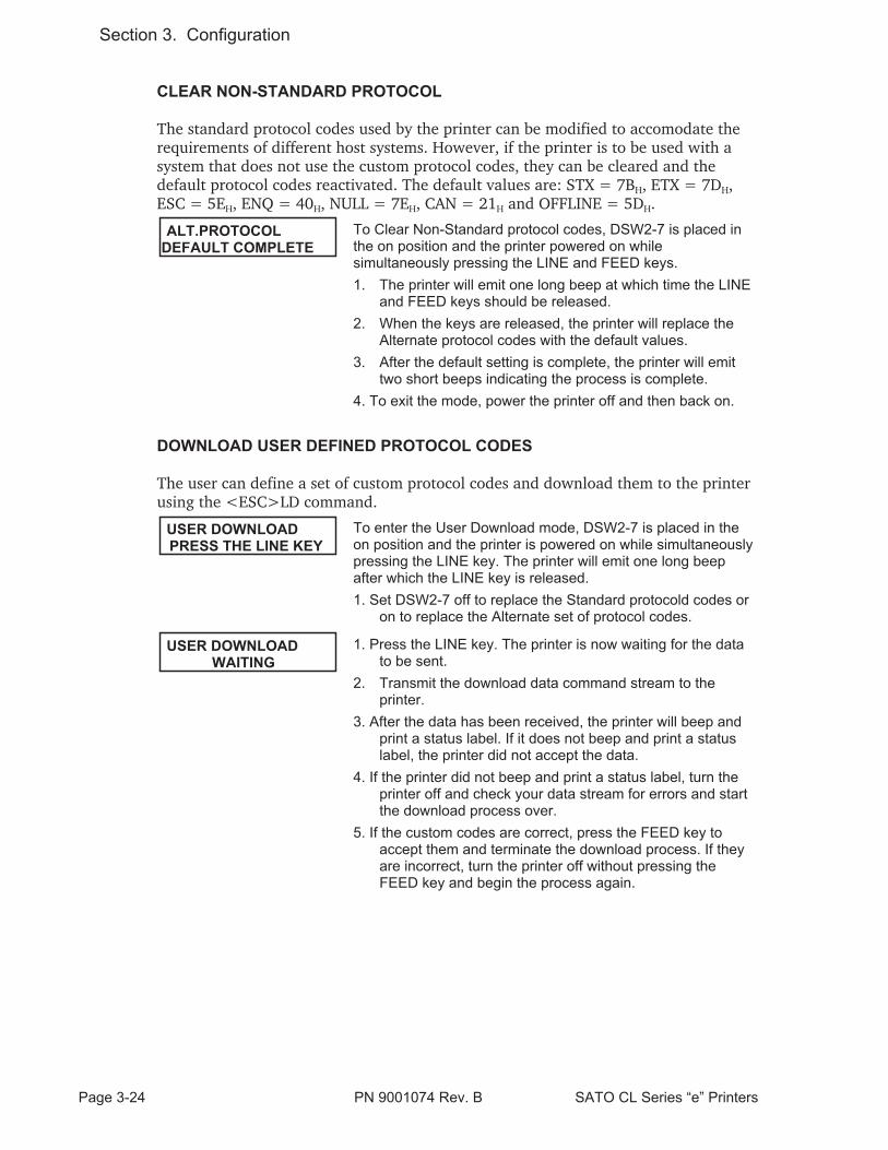
CLEAR NON-STANDARD PROTOCOL
The standard protocol codes used by the printer can be modified to accomodate therequirements of different host systems. However, if the printer is to be used with asystem that does not use the custom protocol codes, they can be cleared and thedefault protocol codes reactivated. The default values are: STX = 7BH, ETX = 7DH,ESC = 5EH, ENQ = 40H, NULL = 7EH, CAN = 21H and OFFLINE = 5DH.
ALT.PROTOCOLDEFAULT COMPLETE
To Clear Non-Standard protocol codes, DSW2-7 is placed inthe on position and the printer powered on whilesimultaneously pressing the LINE and FEED keys.
1. The printer will emit one long beep at which time the LINEand FEED keys should be released.
2. When the keys are released, the printer will replace theAlternate protocol codes with the default values.
3. After the default setting is complete, the printer will emittwo short beeps indicating the process is complete.
4. To exit the mode, power the printer off and then back on.
DOWNLOAD USER DEFINED PROTOCOL CODES
The user can define a set of custom protocol codes and download them to the printerusing the <ESC>LD command.
USER DOWNLOADPRESS THE LINE KEY
To enter the User Download mode, DSW2-7 is placed in theon position and the printer is powered on while simultaneouslypressing the LINE key. The printer will emit one long beepafter which the LINE key is released.
1. Set DSW2-7 off to replace the Standard protocold codes oron to replace the Alternate set of protocol codes.
USER DOWNLOADWAITING
1. Press the LINE key. The printer is now waiting for the datato be sent.
2. Transmit the download data command stream to theprinter.
3. After the data has been received, the printer will beep andprint a status label. If it does not beep and print a statuslabel, the printer did not accept the data.
4. If the printer did not beep and print a status label, turn theprinter off and check your data stream for errors and startthe download process over.
5. If the custom codes are correct, press the FEED key toaccept them and terminate the download process. If theyare incorrect, turn the printer off without pressing theFEED key and begin the process again.
Page 3-24 PN 9001074 Rev. B SATO CL Series “e” Printers
Section 3. Configuration

HEX DUMP MODE
In addition to the Test Print Labels, the printer can print the contents of the receivebuffer in a hexadecimal format to allow the data stream to be examined for errorsand troubleshooting.
ONLINEQTY:000000
The Hex Dump Mode is entered by placing DSW2-4 in the onposition and powering the printer on.
1. The printer is now ready to receive data.
2. Send the data stream to the printer.
3. The received data will be printed in a hexadecimal format
4. To return the printer to normal operation, place DSW2-4 inthe off position and power the printer off and then back on.
SATO CL Series “e” Printers PN 9001074 Rev. B Page 3-25
Section 3. Configuration

This page left intentionally blank.
Page 3-26 PN 9001074 Rev. B SATO CL Series “e” Printers
Section 3. Configuration

SECTION 4.CLEANING AND MAINTENANCE
INTRODUCTION
This section provides information on user maintenance for the CL Series “e” printers.Because they come in two versions that differ mechanically, it is divided into twobasic sections, one covering the procedures for the CL6XXe and the other theprocedures for the CL4XXe. Each section contains the following information.
• Adjusting the Print Quality
• Cleaning the Print Head, Platen and Rollers
• Replacing the Print Head
• Replacing the Fuse
PROCEDURES ALL MODELS
ADJUSTING THE PRINT QUALITY
The CL Series “e” printers are equipped with two different methods of adjusting thequality of the print; print darkness and speed. When adjusting the printer foroptimum print quality, a bar code verifier system should be used. The human eye is apoor judge of the relative widths of the bars in a symbol, a characteristic that isextremely important for good bar code quality.
Darkness (Print)
This adjustment allows the user to control (within a specified range) the amount ofpower that is used to activate the individual print head heat elements. It is importantto find a proper print darkness level based on your particular label and ribboncombination. The printed images should not be too light nor should the ink from theribbon “bleed.” The edges of each image should be crisp and well defined.
The Print Darkness range can be set using the front panel LCD panel or bydownloading the setting using the Print Darkness software command. The darknessranges for the printer are displayed on the LCD panel. The lightest print isrepresented by the smaller value and the darkest print by the highest value. Once therange has been selected, the PRINT Potentiometer on the front panel can be used tomake finer adjustments.
SATO CL Series “e” Printers 9001074 Rev. B Page 4-1

The fine adjustment for Print Darkness is the PRINT potentiometer on the operatorpanel. It provides a continuous range of adjustment, allowing you to make precisechanges. Use a small cross-point screwdriver, turning clockwise for darker print andcounterclockwise for lighter print. See Section 3:Configuration for instructions onperforming potentiometer adjustments
NOTE: The PRINT potentiometer adjustment will affect the darkness in all of thecommand code speed ranges, i.e. if the PRINT potentiometer is adjusted for lighterprint, the darkness will be lighter in all speed ranges selected by the command code.
Print Speed
The other method of controlling print quality is by controlling the speed at which thelabel is printed. This adjustment is made only on an individual label basis using eitherthe Print Speed command code or the LCD display panel. For more details on thiscommand, see Section 5: Programming. Changing the print speed allows the user tocontrol the amount of time allowed for print element cooling before the media isstepped to the next print position. It is especially critical when printing “ladder” barcodes (bar codes printed with the bars parallel to the print line). When printing a“ladder” bar code, it is important to allow the head to cool sufficiently before steppingto the next position. If it does not have sufficient time to cool, the bar will be“smeared” on the trailing edge.
The Print Speed can be set using the LCD panel or with the Print Speed commandcode. The software command will override the any setting entered using the LCDpanel.
CLEANING THE PRINT HEAD, PLATEN AND ROLLERS CL608e and CL612e
Supplies needed: SATO SA070 Cleaning Kit
Cleaning the Print Head
1. Turn the printer off and remove the power cable.
2. Open the Label Access door.
3. Open the Print Head Assembly by pushing the Head Latch toward the rearof the printer. The Print Head Assembly is spring-loaded and willautomatically open as soon as the Head Latch is disengaged. Remove theribbon.
4. Apply SATO Thermal Print Head Cleaner to a cotton swab.
5. The Print Head faces downward along the front edge of the assembly. Pass theend of the dampened swab along the entire width of the Print Head (you mayneed to move the ribbon out of the way to do this).
5. Check for any black coloring or adhesive on the swab after cleaning.
6. Repeat if necessary until the swab is clean after it is passed over the head.
Page 4-2 9001074 Rev. B SATO CL Series “e” Printers
Section 4: Cleaning and Maintenance

7. The head should be cleaned at least every time the ribbon is changed and moreoften in harsh environments.
Cleaning the Platen and Rollers
1. Turn the printer off and remove the power cord.
2. Open the Label Access Door.
3. Open the Print Head Assembly by pushing the Head Latch toward the rearof the printer. The Print Head Assembly is spring-loaded and willautomatically open as soon as the Head Latch is disengaged. Remove the labels.
4. Apply SATO Thermal PrintHead Cleaner to one of thecotton swabs.
5. The Platen is the rubberroller directly below thePrint Head. It should becleaned of any ribbon or labelresidue.
6. The Label Load Roller islocated underneath theLabel Hold-Down. Itshould be cleaned of anylabel residue or foreignmaterial.
SATO CL Series “e” Printers 9001074 Rev. B Page 4-3
Section 3: Cleaning and Maintenance
Roller
Platen
Print Head
MetalRoller

7. There is one metal roller used in guiding the labels through the printer. It shouldbe cleaned of any residue or foreign material.
8. Repeat if necessary. The platen and rollers should be cleaned whenever foreignmatter such as dust or adhesive is present.
REPLACING THE PRINT HEAD CL608e and CL612e
The print head on the CL6XXe printers is a user-replaceable item. If it becomesdamaged for any reason, it can be easily removed and replaced. Contact your localSATO representative for information on obtaining a new print head.
Supplies needed: No. 2 Phillips screwdriver (a magnetic tip is helpful)
1. Turn the printer off and remove the power cable.
2. Open the Label Access door.
3. Open the Print Head Assembly by pushing the Head Latch toward the rearof the printer. The Print Head Assembly is spring-loaded and willautomatically open as soon as the Head Latch is disengaged.
4. Remove the ribbon from the Ribbon Rewind Spindle if necessary.
5. View the Print Head Assembly from the front of the printer. Locate the twomounting screws on the top of the assembly. They are accessible through the twoholes in the Top Assembly Plate. Unscrew these two screws and set themaside.
6. The Print Head should now be loosened from the top of the assembly bygrasping either side and carefully pulling it forward.
Page 4-4 9001074 Rev. B SATO CL Series “e” Printers
Section 4: Cleaning and Maintenance
Mounting Screws
Print Head
SignalConnector
PowerConnector

7. Disconnect the signal and power cables from the print head connectors and setthe Print Head aside.
8. Carefully attach the new print head to the connectors, using caution to make surethe connector keys are correctly positioned.
NOTE: Be careful not to scratch the printing surface of the print head while installingit. Scratching the surface will cause permanent and irreparable damage and is notcovered by the warranty!
9. Locate the two mounting screws in the top plate assembly and align them withthe tapped holes in the new print head.
10. Re-secure the print head by tightening the screws.
CLEANING THE SENSORS CL608e and CL612e
There are two sensors that are used to control the positioning of the label. One is atransmissive see-thru sensor that detects the edge of the label by looking through thebacking paper which is translucent and detecting the presence of the opaque label.The other is a reflective sensor that detects the light reflected from the bottom of thelabel liner. When a printed black Eye-Mark passes through the beam, the light is nolonger reflected back to the sensor detector, indicating to the printer that it shoulduse this position as the start of a new label. When dust, dirt or other foreign matterinterferes with the light path of either of these sensors, the results is erratic labelpositioning. These sensors should be cleaned regularly, at least every two rolls oflabels.
Supplies Needed: SATO SA070 Cleaning Kit
1. Turn the printer off and remove the power cable.
2. Open the Label AccessDoor.
3. Open the LabelHold-Down by disengagingthe latch. The LabelHold-Down is springloaded and will stay in theup position. Two rectangularholes will be visibleunderneath the LabelHold-Down when it israised. These are locatedapproximately 1 and 2inches in from the printerside plate.
4. Apply SATO Thermal PrintHead Cleaner to one of thecotton swabs.
SATO CL Series “e” Printers 9001074 Rev. B Page 4-5
Section 3: Cleaning and Maintenance
Sensors located beneathLabel Hold-Down
Label Hold-DownAssembly
5. Use the cotton swab to clean any foreign matter from the exposed surface of thesensors.
REPLACING THE FUSE CL608e and CL612e
Supplies needed: 250V 3A Fuse
1. Turn the printer power off and remove the power cable.
2. On the back of the printer, locate the Fuse Cap directly above the AC connector.
3. Unscrew the cap and remove the defective fuse.
4. Replace with a new 250V 3A fuse.
5. Screw the cap back onto the printer and replace the power cord.
Page 4-6 9001074 Rev. B SATO CL Series “e” Printers
Section 4: Cleaning and Maintenance

CLEANING THE PRINT HEAD AND PLATEN CL408e and CL412e
Supplies needed: SATO SA070 Cleaning Kit
Cleaning the Print Head
1. Turn the printer off andremove the power cableand open the Top AccessDoor.
2. Open the Print HeadAssembly by rotating thegreen Head Latchcounter-clockwise. ThePrint Head Assembly isspring-loaded and willautomatically open assoon as the Head Latchis disengaged. Remove theribbon.
3. Apply SATO Thermal Print Head Cleaner to a cotton swab.
4. The Print Head faces downward along the front edge of the assembly. Pass theend of the dampened swab along the entire width of the Print Head (you mayneed to move the ribbon out of the way to do this).
5. Check for any black coloring or adhesive on the swab after cleaning.
6. Repeat if necessary until the swab is clean after it is passed over the head.
7. The head should be cleaned at least every time the ribbon is changed and moreoften in harsh environments.
Cleaning the Platen
1. Turn the printer off and remove the power cord.
2. Open the Print Head Assembly by rotating the green Head Latchcounter-clockwise. The Print Head Assembly is spring-loaded and willautomatically open as soon as the Head Latch is disengaged. Remove the labels.
3. Apply SATO Thermal Print Head Cleaner to one of the cotton swabs.
4. The Platen is the rubber roller directly below the Print Head. It should becleaned of any ribbon or label residue.
5. Repeat if necessary. The platen and rollers should be cleaned whenever foreignmatter such as dust or adhesive is present.
SATO CL Series “e” Printers 9001074 Rev. B Page 4-7
Section 3: Cleaning and Maintenance
Platen
Print Head

REPLACING THE PRINT HEAD CL408e and CL412e
The print head on the CL4XXe printers is a user-replaceable item. If it becomesdamaged for any reason, it can be easily removed and replaced. Contact your localSATO representative for information on obtaining a new print head.
Supplies needed: No. 2 Phillips screwdriver (a magnetic tip is helpful)
1. Turn the printer off and removethe power cable and open theTop Access Door.
2. Open the Print HeadAssembly by rotating the greenHead Latch counter-clockwise.The Print Head Assembly isspring-loaded and willautomatically open as soon asthe Head Latch is disengaged.
3. Remove the ribbon from theRibbon Rewind Spindle ifnecessary.
4. View the Print Head Assembly from the front of the printer. Locate the singlemounting screw on the top of the assembly. It is accessible through the hole in theTop Assembly Plate. Unscrew the screw and set it aside.
5. The Print Head should now be loosened from the top of the assembly bygrasping either side and carefully pulling it forward.
6. Disconnect the signal and power cables from the print head connectors and setthe Print Head aside.
7. Carefully attach the new print head to the connectors, using caution to make surethe connector keys are correctly positioned.
NOTE: Be careful not to scratch the printing surface of the print head whileinstalling it. Scratching the surface will cause permanent and irreparable damageand is not covered by the warranty!
8. Locate the mounting screw in the top plate assembly and align it with the tappedhole in the new print head.
10. Re-secure the print head by tightening the screw.
Page 4-8 9001074 Rev. B SATO CL Series “e” Printers
Section 4: Cleaning and Maintenance

CLEANING THE SENSORS CL408e and CL412e
There are two sensors that are used to control the positioning of the label. One is atransmissive see-thru sensor that detects the edge of the label by looking through thebacking paper which is translucent and detecting the presence of the opaque label.The other is a reflective sensor that detects the light reflected from the bottom of thelabel liner. When a printed black Eye-Mark passes through the beam, the light is nolonger reflected back to the sensor detector, indicating to the printer that it shoulduse this position as the start of a new label. When dust, dirt or other foreign matterinterferes with the light path of either of these sensors, the results is erratic labelpositioning. These sensors should be cleaned regularly, at least every two rolls oflabels.
Supplies Needed: SATO SA070 Cleaning Kit
1. Turn the printer off and removethe power cable.
2. Open the label Top AccessDoor.
3. Open the Print Head Assemblyby rotating the green Head Latchcounter-clockwise. The PrintHead Assembly is spring-loadedand will automatically open assoon as the Head Latch isdisengaged.
4. Apply SATO Thermal Print Head Cleaner to one of the cotton swabs.
5. Insert the cotton swab between the top and bottom pieces of the Sensor Unitand move back and forth to clean any foreign matter from the exposed surface ofthe sensors.
REPLACING THE FUSE CL408e and CL412e
Supplies needed: 250V 3A Fuse
1. Turn the printer power off and remove the power cable..
2. On the back of the printer, locate the Fuse Cap directly above the AC connector.
3. Unscrew the cap and remove the defective fuse.
4. Replace with a new 250V 3A fuse.
5. Screw the cap back onto the printer and replace the power cord.
SATO CL Series “e” Printers 9001074 Rev. B Page 4-9
Section 3: Cleaning and Maintenance
Label Sensor Unit

This page left intentionally blank.
Page 4-10 9001074 Rev. B SATO CL Series “e” Printers
Section 4: Cleaning and Maintenance

SECTION 5.PROGRAMMING REFERENCE
Information on programming the Cle Series printers can be found in the “e” and PROPrinter Programming Reference, PN 9001096 found on the Printer Utilities CD-ROM.
SATO CL Series “e” Printers PN 9001074 Rev. B Page 5-1

This page left intentionally blank.
SATO CL Series “e” Printers PN 9001074 Rev. B Page 5-2

SECTION 6.INTERFACE SPECIFICATIONS
INTRODUCTION
The CL Series “e” printers utilize a Plug-In Interface Module for maximum printerconfiguration flexibility. This section presents the interface specifications for the CLSeries “e” Series printers. These specifications include detailed information on how toproperly interface your printer with your host system.
The following information is presented in this section:
• Interface Types
• Using the Receive Buffer
• IEEE1284 Parallel Interface
• Universal Serial Bus (USB) Interface
• Local Area Network (LAN) Interface
• RS232C Serial InterfaceGeneral SpecificationsElectrical SpecificationsPin AssignmentsReady/Busy Flow ControlX-On/X-Off Flow ControlBi-Directional Communications Protocol
INTERFACE TYPES
The parallel interface for the CL Series “e” printers is a high speed, bi-directionalinterface that conforms to the IEEE1284 specification (ECP mode on somecomputers). The interface is also compatible with the older Centronics parallelinterface standard. If it does not detect the correct IEEE1284 signals in the interfaceconnection, it will automatically operate in the standard Centronics mode which ismuch slower. To use the IEEE1284 parallel interface to its fullest capability requiresthat the host also have an IEEE1284 compatible interface and that the two beconnected with a cable that meets the IEEE1284 specification. If either of these twoare not present, the data rate is severely compromised.
In order to provide flexibility in communicating with a variety of host computersystems all “e” printers use a Plug-In Interface Module. The IEEE1284 Interfacemodule is shipped with the printer unless another interface type is specified at thetime of the order. The other interfaces available are a high speed (to 57.6K bps) serialinterface, an Ethernet interface or an optional Universal Serial Bus (USB) interface.
The Parallel interface will probably be the most useful in communicating with IBMPCs and compatibles. The RS232C Serial interface allows connectivity to a number ofother hosts. The USB interface allows the printer to be connected to a computer thatsupports peripherals attached to a USB bus. Up to 127 peripherals can be connectedto a single USB port.
SATO CL Series “e” Printers PN 9001074 Rev. B Page 6-1

WARNING: Never connect or disconnect interface cables (or use a switch box) withpower applied to either the host or the printer. This may cause damage to theinterface circuitry in the printer/host and is not covered by warranty.
THE RECEIVE BUFFER
The CL Series “e” printers have the ability to receive a data stream from the host inone of two ways. The receive buffer may be configured to accept one print job at atime or multiple print jobs. The single job print buffer is generally used by softwareprograms that wish to maintain control of the job print queue so that it can move ahigh priority job in front of ones of lesser importance. The multiple job buffer, on theother hand prints all jobs in the order they are received by the printer, and the orderof printing cannot be changed.
Single Job Buffer
The printer receives and prints one job at a time. Each job must not exceed 2.95MB.
Multi Job Buffer
The printer is able to continuously receive print jobs, compiling and printing otherjobs at the same time. It acts much like a “print buffer” to maximize the performanceof the host and the printer.
When using the RS232 Serial interface, the Multi Job Buffer uses either theReady/Busy with DTR (pin 20) or X-On/X-Off flow control protocols. See thesesections for more details. With an empty receiving buffer, the status of DTR is “high”(or an X-On status if using X-On/X-Off), meaning the printer is ready to receivedata. When the receive buffer is holding 2.0MB of data (1MB from being full), DTR
Page 6-2 PN 9001074 Rev. B SATO CL Series “e” Printers
Section 6. Interface Specifications

will go “low” (or an X-Off is sent) indicating the printer can no longer receive data.This condition is called “Buffer Near Full.”will go “low” (or an X-Off is sent) indicating the printer can no longer receive data.This condition is called “Buffer Near Full.”will go “low” (or an X-Off is sent) indicating the printer can no longer receive data.This condition is called “Buffer Near Full.”
The receiving buffer will not be able to receive more data again until a “BufferAvailable” condition occurs. This takes place when the receiving buffer has emptied sothat only 1MB bytes of data are being held (2.0MB bytes from being full). At thistime, DTR will go “high” or an X-On is sent to tell the host that it can again receivedata.
All printer error conditions (i.e., label out, ribbon out) will cause the printer to gobusy (DTR “low” or X-Off) until the problem is corrected and the printer is placedon-line. The printer will also be busy if taken off-line from the front panel.
IEEE1284 PARALLEL INTERFACE
The parallel interface for the CL Series “e” printers is a Plug-In Interface Module thatcan be installed by the user. It conforms to the IEEE1284 specification. It willautomatically detect the IEEE1284 signals and operate in the high speed mode. If itdoes not detect the IEEE1284 signals, it will operate in the standard Centronics mode,which is significantly slower. For this reason, an interface cable and host interfaceconforming to the IEEE1284 specification must be present to fully utilize the speedcapabilities. This interface also operates bi-directionally and can report the status ofthe printer back to the host.
ELECTRICAL SPECIFICATIONS
Printer Connector AMP 57-40360 (DDK) or equivalent
Cable Connector AMP 57-30360 (DDK) or equivalent
SATO CL Series “e” Printers PN 9001074 Rev. B Page 6-3
Section 6. Interface Specifications
0 1MB 2.95MB
DTR Lowor
X-Off
DTR Highor
X-On
Buffer Available
2.0MB 2.95MB0
DTR Highor
X-OnDTR Low
orX-Off
Buffer Near Full

Cable IEEE1284 Parallel, 10 ft. (3 m) or less
Signal Level High = +2.4V to +5.0VLow = 0V to -0.4V
DATA STREAMS
<ESC>A . . Job#1 . . <ESC>Z<ESC>A . . Job#n . . <ESC>Z
Page 6-4 PN 9001074 Rev. B SATO CL Series “e” Printers
Section 6. Interface Specifications
PIN SIGNAL DIRECTION PIN SIGNAL DIRECTION
1 STROBE To Printer 19 STROBE Re-turn
Reference
2 DATA 1 To Printer 20 DATA 1 Return Reference
3 DATA 2 To Printer 21 DATA 2 Return Reference
4 DATA 3 To Printer 22 DATA 3 Return Reference
5 DATA 4 To Printer 23 DATA 4 Return Reference
6 DATA 5 To Printer 24 DATA 5 Return Reference
7 DATA 6 To Printer 25 DATA 6 Return Reference
8 DATA 7 To Printer 26 DATA 7 Return Reference
9 DATA 8 To Printer 27 DATA 8 Return Reference
10 ACK To Host 28 ACK Return Reference
11 BUSY To Host 29 BUSY Return Reference
12 PTR ERROR To Host 30 PE Return Reference
13 SELECT To Host 31 INIT From Host
14 AUTOFD (1) To Host 32 FAULT To Host
15 Not Used 33 Not Used
16 Logic Gnd 34 Not Used
17 FG Frame Ground 35 Not Used
18 +5V (Z=24K ohm) To Host 36 SELECTIN (1) From Host
(1) Signals required for IEEE1284 mode.
IEEE1284 Parallel Interface Pin Assignments

OPTIONAL RS232C SERIAL INTERFACE
The High Speed Serial Interface is a Plug-In Interface Module that can be installed inthe printer by the user.
GENERAL SPECIFICATIONS
Asynchronous ASCII Half-duplex communication
Ready/Busy Hardware Flow ControlPin 20, DTR ControlPin 4, RTS Error Condition
X-On/X-Off Software Flow Control
Bi-Directional Communication
Data Transmission Rate 9600, 19200, 38400, 57600 bps
Character Format 1 Start Bit (fixed)7 or 8 data bits (selectable)Odd, Even or No Parity (selectable)1 or 2 Stop bits (selectable)
ELECTRICAL SPECIFICATIONS
Connector DB-25S (Female)
Cable DB-25P (Male), 50 ft. maximum length. For cableconfiguration, refer to Cable Requirements appropriateto the RS232C protocol chosen.
Signal Levels High = +5V to +12VLow = -5V to -12V
PIN ASSIGNMENTS
SATO CL Series “e” Printers PN 9001074 Rev. B Page 6-5
Section 6. Interface Specifications
Pin 1Pin 13
Pin 25 Pin 14

Cable Requirements
READY/BUSY FLOW CONTROL
Ready/Busy is the hardware flow control method for the serial interface on the Seprinters. By raising/lowering the voltage level on Pin 20 of the RS232 port, theprinter notifies the host when it is ready to receive data. Pin 4 (RTS) and pin 20(DTR) are the important signals on the printer for this method of flow control. The
Page 6-6 PN 9001074 Rev. B SATO CL Series “e” Printers
Section 6. Interface Specifications
DB9 DB25 HOST INTERCONNECTION PRINTER
1 1 FG ←⎯⎯⎯⎯⎯⎯⎯⎯⎯→ 1 FG (Frame Ground)
2 3 RD ←⎯⎯⎯⎯⎯⎯⎯⎯⎯⎯ 2. TD (Transmit Data)
3 2 TD ⎯⎯⎯⎯⎯⎯⎯⎯⎯⎯→ 3 RD (Receive Data)
8 5 CTS ←⎯⎯⎯⎯⎯⎯⎯⎯⎯⎯ 4 RTS (Request to Send)
7 4 RTS ⎯⎯⎯⎯⎯⎯⎯⎯⎯⎯→ 5 CTS (Clear to Send)
4 20 DTR ⎯⎯⎯⎯⎯⎯⎯⎯⎯⎯→ 6 DSR (Data Set Ready)
6 6 DSR* ←⎯⎯⎯⎯⎯⎯⎯⎯⎯⎯ 20 DTR (Data Terminal Ready)
5 7 SG ←⎯⎯⎯⎯⎯⎯⎯⎯⎯→ 7 SG (Signal Ground)
* This connection at the host side of the interface would depend upon the pin that is being used as the Ready/Busy signal by thedriving software. Typically, on a PC, it would be either CTS (pin 5) or DSR (pin 6) on a DB-25 connector.
PIN DIRECTION SIGNAL DEFINITION
1 Reference FG (Frame Ground)
2 To Host TD (Transmit Data) - Data from the printer to the host computer.Sends X-On/X-Off characters or status data (Bi-Directionalprotocols).
3 To Printer RD (Receive Data) - Data to the printer from the host computer.
4 To Host RTS (Request to Send) - Used with Ready/Busy flow control toindicate an error condition. RTS is high and remains high unlessthe print head is open (in this case, RTS would return to the highstate after the print head is closed and the printer is placed backon-line) or an error condition occurs during printing (e.g., ribbonout, label out).
5 To Printer CTS (Clear to Send) - When this line is high, the printer assumesthat data is ready to be transmitted. The printer will not receivedata when this line is low. If this line is not being used, it should betied high (to pin 4).
6 To Printer DSR (Data Set Ready) - When this line is high, the printer will beready to receive data. This line must be high before data istransmitted. If this line is not being used, it should be tied high (topin 20).
7 Reference SG (Signal Ground)
20 To Host DTR (Data Terminal Ready) - This signal applies to Ready/Busyflow control. The printer is ready to receive data when this pin ishigh. It goes low when the printer is off-line, either manually or dueto an error condition, and while printing in the Single Job Buffermode. It will also go low when the data in the buffer reaches theBuffer Near Full level.
RS232C Interface Signals

host must be capable of supporting this flow control method for it to functionproperly.
X-On/X-Off FLOW CONTROL
X-On/X-Off flow control is used whenever hardware (Ready/Busy) flow control isnot available or desirable. Instead of a voltage going high/low at pin 20, controlcharacters representing “Printer Ready” (X-On =11 hexadecimal) or “Printer Busy”(X-Off = 13 hexadecimal) are transmitted by the printer on pin 2 (Transmit Data) tothe host. In order for this method of flow control to function correctly, the host mustbe capable of supporting it. X-On/X-Off operates in a manner similar to the functionof pin 20 (DTR) as previously explained. When the printer is first powered on itsends an X-Off when the “Buffer Near Full” level is reached and a X-On when thedata level of the buffer drops below the “Buffer Available” mark. When the printer istaken off-line manually, it transmits an X-Off indicating it cannot accept data. Whenit is placed back on line manually, it sends an X-On, indicating it is again availablefor receipt of data. If an error occurs during printing (paper out, ribbon out), theprinter sends an X-Off as soon as an error condition is detected. When the error iscleared and the printer is placed back on-line, it transmits an X-On indicating it isagain ready to accept data.
Upon power up if no error conditions are present, the printer will continually sendX-On characters at five millisecond intervals until it receives a transmission from thehost.
Data Streams
The data streams for X-On/X-Off and Ready/Busy flow control are constructed inthe same way as they are for Ready/Busy flow control.
<ESC>A . . Job#1 . . <ESC>Z<ESC>A . . Job#n . . <ESC>Z
Example: <ESC>A . . Job#1 . . <ESC>Z
NOTE: All charactersare in ASCII.
UNIVERSAL SERIAL BUS (USB) OPTIONAL INTERFACE
The Universal Serial Bus (USB) interface is a Plug-In Interface Module that can beinstalled by the user. It requires a driver (shipped with each printer that has theinterface installed) that must be loaded on your PC and the PC must be configured tosupport USB peripherals using Windows 98. Details for loading the USB driver arecontained in the USB Interface Manual that is shipped with each printer with a USBOptional interface installed. Up to 127 devices may be connected to a USB port.
SATO CL Series “e” Printers PN 9001074 Rev. B Page 6-7
Section 6. Interface Specifications

LOCAL AREA NETWORK (LAN) OPTIONAL INTERFACE
A Local Area Network (LAN) interface is a Plug-In Interface Module that can beinstalled by the user. It requires a driver shipped with each printer that has theinterface installed. The driver that must be loaded on your PC and the PC must beconfigured to support the TCP/IP network protocol using a 10/100BaseT LANconnection. Details for loading the LAN driver are contained in the LAN InterfaceManual that is shipped with each printer with a LAN Optional interface installed.
BI-DIRECTIONAL COMMUNICATIONS
This is a two-way communications protocol between the host computer and theprinter, thus enabling the host to check printer status. When Bi-Com 4communications is selected, there is no busy signal from the printer. The host mustrequest the complete status from the printer, including ready/busy. The host mayrequest status in two different ways.
ENQUIRE/ACK/NAK
In the Bi-Com 4 mode, the host transmits an ENQ (05 hexadecimal) to the printerand the printer will respond with its status within five milliseconds. If printing, it willrespond upon finishing the current label, then resume printing. In order for thisprotocol to work properly with an RS232 Optional Interface, pin 6 (DTR) and pin 5(CTS) must be held high by the host. One way to ensure these pins are always in thecorrect state is to tie pin 20 (DTR) to pin 6 (DSR) and pin 4 (RTS) to pin 5 (CTS) atthe printer end of the cable.
Enquire (ENQ)
Upon receipt of an ENQ command, the printer responds with 25 bytes of statusinformation bounded by an STX/ETX pair. The Bi-Com protocol works only in theMulti Job Buffer mode. The status information is defined as follows:
<STX>{ 2 Byte ID}{1 Status Byte}{6 Byte Label Remaining}{16 Byte Job Name}<ETX>
ID - This is a two byte number identifying the current print job ID. The printjob ID is defined using the <ESC>ID Job ID command transmitted with theprint job (see Job ID Store in the command listing for more information onhow to use this command). The range is from 00 to 99.
Status - A single byte defining the current status of the printer (see the StatusByte Definition table).
Label Remaining - Six bytes defining the number of labels remaining in thecurrent print job. The range is from 000000 to 999999 labels.
Job Name - 16 bytes of ASCII characters identifying the name assigned tothe job by the <ESC>WK Job Name command. If the Job Name is less than16 characters, the field will be padded with leading zeroes.
If an ENQ is received after the print job specified in the ID bytes has been completed,or there is no data in the buffer, the printer will respond with two “space” characters
Page 6-8 PN 9001074 Rev. B SATO CL Series “e” Printers
Section 6. Interface Specifications

(20 hexadecimal) for the ID number, six “zero” characters (30 hexadecimal) in theRemaining Labels bytes and the 16 byte Job Name.
Cancel (CAN)
If a CAN (18 hexadecimal) command is received , it will stop the print job and clearall data from the receive and print buffers. A delay of five milliseconds or more isrequired before any new data can be downloaded. The CAN command is effectiveimmediately upon receipt, even if the printer is off-line or in an error condition. Theprinter will return an ACK (06 hexadecimal) if there is no printer error condition anda NAK (15 hexadecimal) if an error condition exists.
Print Job
Upon receipt of a valid print job (<ESC>A . . . <ESC>Z), an ACK (06hexadecimal) will be returned by the printer if there are no errors and a NAK (16hexadecimal) if a printer error exists.
Print Stop (DLE)
If a DLE (10 hexadecimal) is received by the printer, the print process is stopped andan ACK (06 hexadecimal) is returned if there are no errors and a NAK (16hexadecimal) if a printer error exists.
Print Start (DC1)
If the printer has been stopped by receipt of a DLE (10 hexadecimal) command, itcan be restarted by sending a DC1 (hexadecimal 11) command. Upon receipt of thiscommand an ACK (06 hexadecimal) is returned if there are no errors and a NAK (16hexadecimal) if a printer error exists.
(1) To provide compatibility with older SATO printers, the RS232 interface can beconfigured to use an earlier Bi-Com 3 ENQ/ACK/NAK protocol selected via DSW2-8and DSW1-7/8 (on the RS232 Interface module).The earlier protocol did not haveprovisions for the Job Name and did not respond to the DLE or DCI commands.Also, there are additional Response Codes in the Status Byte Definition. It isrecommended that you use the current protocol rather than the earlier version unlessit is necessary for compatibility with existing software.
SATO CL Series “e” Printers PN 9001074 Rev. B Page 6-9
Section 6. Interface Specifications

Page 6-10 PN 9001074 Rev. B SATO CL Series “e” Printers
Section 6. Interface Specifications
ASCII HEX DEFINITION
OFF-LINE
0 30 No Errors
1 31 Ribbon Near End
2 32 Buffer Near Full
3 33 Ribbon Near End and Buffer Near Full
4 (1) 34 Print Stop (no error)
ON-LINE, WAITING FOR DATA
A 41 No Errors
B 42 Ribbon Near End
C 43 Buffer Near Full
D 44 Ribbon Near End and Buffer Near Full
E(1) 45 Print Stop (without error)
ON-LINE, PRINTING
G 47 No Errors
H 48 Ribbon Near End
I 49 Buffer Near Full
J 4A Ribbon Near End and Buffer Near Full
K(1) 4B Print Stop (without error)
ON-LINE, WAITING TO DISPENSE A LABEL
M 4D No Errors
N 4E Ribbon Near End
O 4F Buffer Near Full
P 50 Ribbon Near End and Buffer Near Full
Q(1) 51 Print Stop (without error)
ON-LINE, COMPILING PRINT JOB
S 53 No Errors
T 54 Ribbon Near End
U 55 Buffer Near Full
V(1) 56 Ribbon Near End and Buffer Near Full
W(1) 56 Print Stop (without error)
OFF-LINE, ERROR CONDITION
b 62 Head Open
c 63 Paper End
d 64 Ribbon End
e 65 Media Error
f 66 Sensor Error
g 67 Head Error
j 6A Cutter Error
k 6B Other Error Condition
(1) Not supported by legacy Bi-Com protocols
Status Byte Definition, Bi-Com Protocol

STATUS RESPONSE
The second method of determining printer status is to interrograte the printer withspecific commands. The response from these commands will provide specificinformation about the printer status depending upon the command. This allows thecontrolling application to determine the status of a printer when it is located in aremote location. Details on the Status Response mode are found in the “e” and PROPrinter Programming Reference, PN 9001096, found on the Printer Utilities CD-ROM.
SATO CL Series “e” Printers PN 9001074 Rev. B Page 6-11
Section 6. Interface Specifications

EXT CONNECTOR
The EXT connector on the rear panel of the CL Series “e” printers is intended for usewith the external printer accessories such as label rewinders or applicators. The14-pin Centronics type connector provides a choice of four different output signalsalong with various error conditions.
Pin Assignments
PIN DIRECTION SIGNAL DESCRIPTION
13 To Host Vcc - +5V
10 To Host Ribbon Near End - This pin goes high when the amount of ribbonon the unwind shaft is approximately 46 feet (14 m). The outputwill be low when the ribon is completely out.
4 To Host Error - This pin goes low when the printer detects an errorcondition such as head open or receiving buffer full.
7 To Printer Reprint - A duplicate of the last label in a print job will be reprintedwhen this signal is received.
5 To Printer Print Start - The printer will print one label when this pin is pulledto ground. This signal must be enabled by placing switch DSW3-5on the Control Panel in the OFF position.
6 To Host End Print - It is used to drive an applicator or other external devicerequiring synchronization with the print cycle. You may choosebetween four types of output signals using control panel DSW3-6and DSW3-7 selections.See timing charts on next page.
1 To Host Label Out - This pin goes low (0V) when a label out error exists.
3 To Host Ribbon Out - This pin goes low (0V) when the ribbon is out.
2 Reference Signal Ground
8 To Printer Reserved
9 To Host Off Line - This pin goes low (0V) when the printer if Off Line.
11 Reserved
12 To Host +24V +/- 10% @2A - Power for external devices.
14 Frame Ground
Page 6-12 PN 9001074 Rev. B SATO CL Series “e” Printers
Section 6. Interface Specifications
NOTE: The signals on pins 1, 3, 4, 6, 9 and 10 each have an open collector output. These pins normally measure+.07V maximum when a true condition exists. If a false condition occurs, the voltage will drop to 0V. To achieve a sig-nal level of +5V, you must add a 330 ohm, 1/4W pull-up resistor between the open collector output pin and Vcc (pin13) as illustrated . This will provide a signal level of +5V for a true condition and 0V when a false condition exists. Themaximum voltage that can be applied to these pins is +50V and the maximum current they can sink is 500 milliamps.

SATO CL Series “e” Printers PN 9001074 Rev. B Page 6-13
Section 6. Interface Specifications
0V
+5V
+5V
0V
+5V
0V
20 milliseconds
Start of Print Cycle End of Print Cycle
0V
+5V
Print EndType 1
Print EndType 2
Print EndType 3
Print EndType 4
Print RepeatInput
Print StartInput
+5V
0V
+5V
0V
STANDARD OPERATION
Vcc= +5VPin 13
330 ohm, 1/4W
Pin 1, 3, 4, 6, 9 or 10
Signal Out

Page 6-14 PN 9001074 Rev. B SATO CL Series “e” Printers
Section 6. Interface Specifications
ERROR SIGNALS
+5V
0V
+5V
0V
+5V
0V
0V
+5V
Print Motion
Print EndType 1
Print EndType 2
Print EndType 3
Print EndType 4
Stopped
Moving
Paper or Ribbon End
+5V
0V
+5V
0V
+5V
0V
Ribbon End
Paper End
Machine Error
HeadClosed
HeadOpen
Paper/RibbonReplinished
0V
+5V
+5V
0V
+5V
0V
20 milliseconds
Start of Print Cycle End of Print Cycle
0V
+5V
Print EndType 1
Print EndType 2
Print EndType 3
Print EndType 4
Print RepeatInput
Print StartInput
+5V
0V
+5V
0V
REPEAT PRINT

SECTION 7.TROUBLESHOOTING
This section has been devised to help you if you are unable to produce output on theCL Series “e” printers. Use this section to make sure the basics have been checkedbefore deciding you are unable to proceed any further. The section is divided intothree parts:
• Initial Checklist
• IEEE1284 Parallel Interface
• RS232C Serial Interface
INITIAL CHECKLIST
1. Is the printer powered up and ON-LINE?
2. Is the ERROR light on the front panel off? Is this light is on, it may meanthe Print Head Assembly or the Label Hold-Down is not closed and latchedin position..
3. Are the LABEL and RIBBON lights on the front panel off? If these lights areon, the labels or ribbons may be incorrectly loaded.
USING THE IEEE1284 PARALLEL INTERFACE
1. Is the IEEE1284 printer cable connected securely to your parallel port(DB-25S Female) on the PC and to the Parallel Interface connector on theprinter?
WARNING: Never connect or disconnect interface cables (or use a switch box)with power applied to either the printer or the host. This may cause damageto the interface circuitry and is not covered by warranty.
2. Does the Parallel interface cable used meet IEEE1284 specifications? If itdoes not and you are connected to an IEEE1284 or ECP parallel port onthe computer, the printer may not be able to communicate correctly.
3. Is there more than one parallel interface port on your PC (LPT1, LPT2,etc.)? If so, make sure you are sending data out the correct port.
4. Is the IEEE1284 Interface Module installed in the printer? Older versionsof the Parallel Interface module will not work correctly in the “e” printers.
5. When you send the print job to the printer, and it does not respond, doyou get an error message on your PC that says “Device Fault” or somethingsimilar?
SATO CL Series “e” Printers PN 9001074 Rev. B Page 7-1

This may mean that the computer doesn’t know the printer is there. Verifythat:
a. Both ends of the cable are securely inserted into their respectiveconnectors.
b. The printer is ONLINE.
c. The cable is not defective. There are other things that can cause thiserrormessage on your computer, but at this stage, a defective cable may be oneof the reasons.
5. When you send the print job to the printer and it does not respond, andthere is no error message on the PC:
a. Check your data stream for some of the basics. Is your job framed asfollows?
<ESC>A—DATA—<ESC>Z
b. Verify that you’ve included all required parameters in the data stream.
c. Verify the following:
• You have not typed a “0” (zero) for an “O” (letter) or vice-versa.
• You have not missed any <ESC> characters where they’re needed.
• Make sure all printer command codes are capital letters.
6. If you’ve checked all of the above and the printer still isn’t printing, youmay want to try a Buffer Hex Dump to determine what (if anything) theprinter is receiving from your computer. See Printing Hex Dump Labels inSection 3.
The Parallel port is now listening for incoming data. Send your print job.The printer will now print (only once) a Hexadecimal (Hex) Dump ofeverything it received from the host computer. Each 2-digit hexadecimalcharacter represents a character the printer received. It may be tedious,but now you can analyze and troubleshoot the data stream.
7. While checking the Hex Dump printout, if you notice 0DH 0AH (CarriageReturn and Line Feed) characters throughout. The command string shouldbe continuous and no CR or LF characters are allowed between the StartCommand (<ESC>A) and the Stop Command (<ESC>Z). If you areusing BASIC, it may be adding these characters automatically as the linewraps. Adding a “width” statement to your program can help to suppressthese extra 0DH 0AH characters by expanding the line length up to 255characters. See the “e” and PRO Printer Programming Reference, PN9001096, for details on writing a program in BASIC.
If you’re not programming in BASIC, check to see if you have anequivalent statement in the language you’re using to suppress extra
Page 7-2 PN 9001074 Rev. B SATO CL Series “e” Printers
Section 7. Troubleshooting

carriage returns and line feeds from your data being sent out to theprinter. We want the data stream to be one complete line going to theprinter.
USING THE RS232C SERIAL INTERFACE
1. Is the RS232C Serial cable connected securely to your serial port on the PC(DB- 25S or DB-9S Male) and to the RS232C connector on the printer?
WARNING: Never connect or disconnect interface cables (or use a switch box)with power applied to either the printer or the host. This may cause damageto the interface circuitry and is not covered by warranty.
2. Is the cable defective? At the very least, you should be using a “NullModem Cable,” which crosses pins in a specific manner. This shouldenable your printer to print. But we recommend that you eventually use acable built to specifications as described in Section 6: InterfaceSpecifications.
3. Is the RS232 Interface Module installed in the printer?
4. Check for obvious errors in the data stream. Is the data properly framedwith the <ESC>A and <ESC>Z commands? See Section 5 if necessary.
5. If after sending your job to the printer, it only “beeps” and displays anerror message on the LCD display, you may have a configuration problem.There may be some inconsistencies with the Baud Rate, Parity, Data Bits,or Stop Bits in relation to your host computer. If you are confused as towhat the printer’s current RS232 settings are, print a Configuration Testlabel(see Section 3). It will list all of the current printer configurationsettings.
6. If you still are unable to get printer output, try the Hex Dump as describedin Step 5 under the Parallel Interface troubleshooting. In this case, theprinter monitors the RS232C interface for incoming data.
7. From the Hex Dump, if you are seeing extra 0DH 0AH (CR and LF)characters, and are using BASIC, refer to the beginning of the CommandCode section. It provides hints for writing a SATO program in BASIC.
SATO CL Series “e” Printers PN 9001074 Rev. B Page 7-3
Section 7. Troubleshooting

ERROR SIGNALS
The LCD Display, Front Panel LED Indicators and Buzzer provide a visual/audioindication of the type of error encountered.
LED LCDMESSAGE
AUDIBLEBEEP
ERROR CONDITION TO CLEAR
Error On Machine Error 1 Long Machine Error Cycle power on/off
Error On EEPROM Error 1 Long EEPROM Read/Write Cycle power on/off
Error On Head Error 1 Long Head Cycle power on/off
Error On Sensor Error 3 Short Sensor Cycle power on/off
Error Blinks Card R/W Error 1 Long Memory Card Read/Write Cycle power on/off
Error Blinks Card Low Battery 1 Long Memory Card Battery Low Cycle power on/off
Error Blinks Head Open 3 Short Head Open Close head lever
Error Blinks Cutter Error 3 Short Cutter Cycle Power On/Off
Error OnLine Blinks
PARITY ERROR 3 Short RS232 Parity Error Cycle power on/off
Error OnLine Blinks
Overrun Error 3 Short RS232 Overrun Error Cycle power on/off
Error OnLine Blinks
Framing Error 3 Short RS232 Framing Error Cycle power on/off
Error OnLine Blinks
Buffer Over 3 Short Buffer Overflow Cycle power on/off
Error BlinksLabel On
Paper End 3 Short Label End Open/close Head LeverOpen/close Label Hold-
down
Error BlinksRibbon On
Ribbon End 3 Short Ribbon End Open/close Head LeverOpen/close Label Hold-
down
Error BlinksLabel Blinks
Media Error 3 Short Media Error Open/close Head Lever
Ribbon Blinks None Ribbon Near End Replace ribbon with full roll
Line Blinks None Buffer Near Full Slow down transmissionrate
Page 7-4 PN 9001074 Rev. B SATO CL Series “e” Printers
Section 7. Troubleshooting

APPENDIX A.OPTIONAL ACCESSORIES
INTRODUCTION
This section contains instructions for using the following CL Series “e”optionalfeatures:
• Label Rewinder
• Label Cutter
• Label Dispenser
• PCMCIA Memory Expansion
• Internal Flash ROM Memory Expansion
• Calendar
• Interface Cards
LABEL REWINDER ALL MODELS
The rewinder is an external unit that allows for labels and tags to be rewound in rollsup to 8.5 inches in diameter. It derives its power directly from the printer’s EXTconnector using a built-in cable. The rewinder provides the ability to rewindtags/labels from the printer and subsequently be unwound for later use withapplicators.
Installation
1. Position the Rewinder at the front of the printer and align it with the label slot.(The Rewind Wheel/Spindle should be positioned away from the printer.)
2. Connect the built-in cable from the Rewinder to the EXT connector at the rear ofthe printer.
3. On the Rewinder, remove the metal clamp from the Rewind Spindle.
4. Feed the lead end of the label stock under the first spindle and onto the RewindSpindle. Feed the stock around the spindle once, then replace the metal clampover the label stock. Wind another revolution to ensure the labels are secure onthe spindle.
5. Select the REWIND option on the rewinder, then set the power switch to ON.(The printer must be powered ON for the rewinder to function.)
Removing and Unwinding the Roll
As labels are printed, tension from the rewinder should keep the label stock taut as itwraps itself on the spindle.
SATO CL Series “e” Printers PN 9001074 Rev. B Page A-1

To remove the roll from the spindle, first set the power switch to OFF. Remove themetal clamp, then remove the rewound roll of labels.
To unwind for using with an applicator, first set the power switch OFF. Attach thelead edge of the labels from the rewind spindle to the applicator entry point. Selectthe WIND option on the rewinder, and when ready to begin, set the power switch toON.
LABEL CUTTER ALL MODELS
The label cutter consists of an internal mechanism that will cut labels or tags as theyexit from the printer. The cutter can be used to print labels of various lengths usingcontinuous form label/tag stock or to easily separate labels when there is noperforation at the label gap.
Operator Setup
The following steps should be taken to set up the label cutter.
1. Install the label cutter, following the instructions provided with the unit. Theinstallation time is approximately 20 minutes.
2. Power the printer ON.
3. The printer must be configured to use the Label Cutter option. SwitchesDSW3-1 and DSW3-2 on the front panel are used to configure the printer. Toenable the cutter, DSW3-1 should be in the ON position and DSW3-2 should bein the OFF position.
4. Open the Print Head Assembly and feed the edge of the labels/tags into thecutter assembly and out between the label cutters.
NOTE: Although the cutting blade is fairly well protected, be careful as you feedlabels into the cutter area. You may want to have the printer powered OFF at thispoint.
5. Close the Print Head Assembly and place the printer on-line.
6. The Label Cutter is ready for use.
7. Adjust the cut position using the backfeed adjustment procedures outlined inSection 3: Configuration.
General Operation
The data stream to be sent to the printer may need to be altered to add the CutterCommand. If this command is not used, the cutter will default to cut after every labelassuming it has been enabled in the printer configuration. For more details, see the“e” and PRO Printer Programming Reference. As the labels are printed, they will be cutbased on the the data supplied using the cutter command.
Page A-2 PN 9001074 Rev. B SATO CL Series “e” Printers
Appendix A: Optional Features

LABEL DISPENSE OPTION CL608e and CL612e
The CL608e and CL612e Label Dispense Option is an external mechanism thatprovides the ability to print labels in the “demand” mode. It is attached to rear of theprinter with two screws and is connected to the internal drive mechanism of theprinter. When the label dispenser is installed and configured for operation, the printerdispenses one label at a time, peeling the backing from the label, which allows forimmediate application to the product by the operator.
Operator Setup
The following steps should be taken to set up the Label Dispense Option.
1. Install the option using the instructions provided with the unit. The installationtime is approximately 30 minutes.
2. Power the printer ON.
3. The printer must be configured to used the label dispenser option. SwitchesDSW3-1 and DSW3-2 on the front panel are used to configure the printer. Toenable the dispenser, both DSW3-1 and DSW3-2 should be in the ON position.
4. Remove enough labels from the backing paper to provide 24 to 30 inches ofbacking free from labels.
5. Open the Print Head assembly and feed the backing paper through the printarea in the normal manner.
6. At the label exit area, feed the backing paper down and behind the KnurledRoller, then back down and around the Backing Roller.
7. Feed the backing paper out the slot in the bottom rear of the printer and attach tothe Backing Rewind Spindle.
SATO CL Series “e” Printers PN 9001074 Rev. B Page A-3
Appendix A: Optional Features
Label Dispenser Routing, CL608e/CL612e
KnurledRoller
BackingRoller
BackingRewindSpindle

8. Close the Print Head and place the printer on-line.
9. The Label Dispense Option is ready for use.
LABEL DISPENSE OPTION CL408e and CL412e
The CL408e and CL412e have an internally mounted Label Dispense Optionwhich rewinds the label backing as the labels are stripped. When the LabelDispense Option is installed and configured for operation, the printer dispensesone label at a time, peeling the backing from the label, which allows for immediateapplication to the product by the operator.
Operator Setup
The following steps should be taken to set up the Label Dispense Option.
1. Install the Label Dispense Option using the instructions provided with theunit. The installation time is approximately 30 minutes.
2. Power the printer OFF.
3. The printer must be configured to used the Label Dispense Option. SwitchesDSW3-1 and DSW3-2 on the front panel are used to configure the printer. Toenable the dispenser, both DSW3-1 and DSW3-2 should be in the ON position.
4. Remove enough labels from the backing paper to provide 24 to 30 inches ofbacking free of labels.
5. Open the Top Access Door and the Front Access Door.
6. The Backing Idle Roller is held closed by the green Front Access DoorLatch ( the Front Access Door is held in the closed position by a magnetic latchwhen the Label Dispense Option is installed). Push down on the rear of the
Page A-4 PN 9001074 Rev. B SATO CL Series “e” Printers
Appendix A: Optional Features
Label Backing Path, CL408e/CL412e
BackingTake-UpSpindle
Backing IdleRoller
LabelBacking
FrontAccess Door
SpindleHandle
BackingDrive Roller
BackingRetainerProng

Front Access Door latch until it releases and swing the Backing Idle Rollerout of the way.
7. Open the Print Head and feed the backing paper through the print area in thenormal manner.
8. Route the label backing down the front of the print mechanism and around theBacking Drive Roller.
9. Wrap the backing under and around the Backing Take-Up Spindle, routing itunder the two retainer prongs.
10. Manually turn the Backing Take-Up Spindle counter-clockwise to take up allthe slack in the backing.
11. Swing the Backing Idle Roller back into position until the Front AccessDoor Latch engages.
12. Close the Front Access Door until the magnetic latch engages.
13. Close the Print Head.
14. Close the Top Access Cover.
15. To remove the backing from the Backing Retainer Spindle, pull outward onthe green Spindle Handle. This will slide the rolled-up backing out from underthe two retainer prongs, allowing the label backing to be easily removed anddiscarded.
General Operation
Send your data stream in the normal manner to the printer. Labels should print oneat a time, even if your print quantity command requests more than one label. As thelabels are printed and presented for the operator to remove, the backing paper will be
SATO CL Series “e” Printers PN 9001074 Rev. B Page A-5
Appendix A: Optional Features
Label Dispenser Routing, CL408e/CL412e
BackingTake-UpSpindle
Drive Roller
LabelBacking
IdleRoller

rewound on the spindle. The next label will only print after removing the currentlabel from the label exit path.
Note: The label dispenser will function only if it has been enabled using the frontpanel switches (DSW3-1 and DSW3-2 in the ON positions).
The Label Taken Sensor is adjusted at the factory for the optimal setting for mostlabel material. However, the use of labels with a substantially different opacity mayrequire that the threshold be adjusted. To adjust the threshold of the sensor, use thefollowing procedure:
1. Turn the Label Taken Threshold Potentiometer (located to the right ofwhere the Label Dispense Option connector is plugged into the front panel,all the way clockwise. Turn the Power Switch to the ON position whilesimultaneously pressing the FEED key. When the printer “beeps,” release theFEED key.
2. Make sure there is no label in the Label Taken Sensor. Turn the potentiometercounter-clockwise until the LED illuminates.
3. Place a label in the Label Taken Sensor and check to see if the LED turns off. Ifit does not, turn the potentiometer clockwise until it goes off and repeat steps (b)through (c).
4. Press the FEED key and the printer will print a test label. Press the FEED keyagain to stop the printing and turn the printer OFF.
Page A-6 PN 9001074 Rev. B SATO CL Series “e” Printers
Appendix A: Optional Features

PCMCIA MEMORY CARDS ALL MODELS
Description
The Memory Card Option provides the connectors and interface board for onePCMCIA memory card slot. The PCMCIA memory is selected for use via the<ESC>CC Memory Area Select command. It can be used to store fonts, graphicimages and forms.
Type SRAM or FlashApplicable Specifications PCMCIA Version 2.1 (JEIDA Version 4.1)Size Up to 4MB SRAM or 16MB FlashConnector Pins 68Battery Approximately two years (manufacturer dependent)Write Protect YesLow Battery Detect Yes
Installation
Instructions for installing the Memory Card Option are included with the installationkit.
Error Handling
Memory Card error conditions are indicated to the operator using a combination ofthe ERROR LED on the front panel, the LCD display and the audible indicator.
ERROR DESCRIPTION INDICATION REMEDY
Low Battery - Low batterycondition is detected whenprinter is powered on.
ERROR LED: BlinkingAudible Beep: 1 longDisplay: Card Low Battery
Depress LINE key to printCard Status.
Replace Memory Cardbattery. Note that all datawill be lost when the batteryis removed.
Card R/W Error1. No card is inserted.2. Card is write protected.3. Invalid store/recallnumber.4. Card has not beeninitialized.
ERROR LED: OnAudible Beep: 1 longDisplay: Card R/W Error
Printer must be powered offto reset.
1. Insert card into selectedslot.2. Remove write protect tab.3. Correct program4. Initialize card with BJFcommand
Warning1. Duplicate number.2. Data not in print area.3. Data overflows cardmemory.
Audible Beep: 1 shortDisplay: None
Printer will ignore invalidcommands.
1. Correct program.2. Correct program.3. Use card with morecapacity.
SATO CL Series “e” Printers PN 9001074 Rev. B Page A-7
Appendix A: Optional Features

INTERNAL FLASH ROM MEMORY EXPANSION ALL MODELS
Description
A factory installed option allows the internal FLASH ROM to be expanded from 2MBto 6 MB by adding an additional 4MB. It can be used to store fonts, graphic imagesand form overlays. The Expanded Memory is selected using the <ESC>CC MemoryArea Select command. This option requires the installation of an Expanded Memorypcb and is a factory-only installed option.
Page A-8 PN 9001074 Rev. B SATO CL Series “e” Printers
Appendix A: Optional Features
CALENDARALL MODELS
The Calendar Option allows the date and time to be maintained in the local printerrather than using the system clock. It consists of an integrated circuit modulecontaining the clock components and battery and plugs into a socketon the main pcbassembly. A qualified technician should perform the upgrade as it requiresmodifications to the main PCB assembly. Please call SATO Technical Support if youneed to add this option to an existing printer in the field.
PLUG-IN INTERFACE MODULES ALL MODELS
The CL Series “e” printers have user changable Plug-In Interface Modules. TheInterface Module is accessible from the Rear Panel and is retained by twoscrews. Use the following procedure to replace an interface molule.
1. Turn power off both the printer and the host and remove the power and interfacecables.
WARNING: Never connect or disconnect interface cables (or use a switch box) withpower applied to either the host or the printer. This may cause damage to theinterface circuitry and is not covered by warranty.
2. Remove the two Interface Module Retaining Screws.
3. Grasp the Interface Module and pull it out of the connector.
4. Place the new Interface Module in the slot and press inward firmly until it isproperly seated.
5. Replace the two Interface Card Retaining Screws.
6. If the new Interface Module is for a serial interface, set DSW1 for the properoperation.
7. Connect the interface cable to the connector.
SATO CL Series “e” Printers PN 9001074 Rev. B Page A-9
Appendix A: Optional Features

This page left intentionally blank.
Page A-10 PN 9001074 Rev. B SATO CL Series “e” Printers
Appendix A: Optional Features