Civilian Radioactive Waste Management System Management ...
68
WBS: 1.2.22.3.4 QA: QA Civilian Radioactive Waste Management System Management & Operating Contractor Concept of Operations for Waste Transport, Emplacement, and Retrieval TDR-WER-ME-000001 REV 00 July 2001 Prepared for: U.S. Department of Energy Yucca Mountain Site Characterization Office P.O. Box 30307 North Las Vegas, Nevada 89036-0307 Prepared by: Bechtel SAIC Company, LLC 1180 Town Center Drive Las Vegas, Nevada 89144-6352 Under Contract Number DE-AC08-01RW12101
Transcript of Civilian Radioactive Waste Management System Management ...

WBS: 1.2.22.3.4QA: QA
Civilian Radioactive Waste Management SystemManagement & Operating Contractor
Concept of Operations for Waste Transport, Emplacement, and Retrieval
TDR-WER-ME-000001 REV 00
July 2001
Prepared for:
U.S. Department of EnergyYucca Mountain Site Characterization Office
P.O. Box 30307North Las Vegas, Nevada 89036-0307
Prepared by:
Bechtel SAIC Company, LLC1180 Town Center Drive
Las Vegas, Nevada 89144-6352
Under Contract NumberDE-AC08-01RW12101

TDR-WER-ME-000001 REV 00 July 2001
DISCLAIMER
This report was prepared as an account of work sponsored by an agency of the United States Government. Neitherthe United States Government nor any agency thereof, nor any of their employees, nor any of their contractors,subcontractors or their employees, makes any warranty, express or implied, or assumes any legal liability orresponsibility for the accuracy, completeness, or any third party's use or the results of such use of any information,apparatus, product, or process disclosed, or represents that its use would not infringe privately owned rights.Reference herein to any specific commercial product, process, or service by trade name, trademark, manufacturer,or otherwise, does not necessarily constitute or imply its endorsement, recommendation, or favoring by the UnitedStates Government or any agency thereof or its contractors or subcontractors. The views and opinions of authorsexpressed herein do not necessarily state or reflect those of the United States Government or any agency thereof.


TDR-WER-ME-000001 REV 00 iv July 2001
CONTENTSPage
1. OBJECTIVE AND SCOPE ...................................................................................................... 1
2. QUALITY ASSURANCE ........................................................................................................ 2
3. TECHNICAL REPORT............................................................................................................ 33.1 INTRODUCTION............................................................................................................ 33.2 LOWER-TEMPERATURE ALTERNATIVES .............................................................. 3
3.2.1 Scenario 1: Increased Waste Package Spacing and Extended Ventilation .......... 43.2.2 Scenario 2: De-Rated or Smaller Waste Packages............................................... 43.2.3 Scenario 3: Extended Ventilation and Increased Waste Package Spacing .......... 43.2.4 Scenario 4: Extended Surface Aging, Extended Ventilation, and Increased
Waste Package Spacing........................................................................................ 53.2.5 Scenario 5: Extended Natural Ventilation............................................................ 53.2.6 Scenario Summary ............................................................................................... 5
3.3 CONCEPT OF REPOSITORY OPERATIONS.............................................................. 73.3.1 Preparatory Surface Operations ........................................................................... 8
3.3.1.1 Preparation of the Emplacement Gantry ............................................... 83.3.1.2 Preparation Of The Waste Package Transporter ................................. 113.3.1.3 Engagement Of The Transport Locomotives ...................................... 143.3.1.4 Loading Of The Waste Package/Pallet Assembly............................... 173.3.1.5 Travel Of The Locomotives And Waste Package Transporter To The
North Ramp ......................................................................................... 173.3.1.6 Evaluation of Lower-Temperature Operating Modes on Preparatory
Surface Operations .............................................................................. 183.3.2 Preparatory Subsurface Operations.................................................................... 18
3.3.2.1 Transfer of Emplacement Gantry from Surface Facilities to anEmplacement Drift .............................................................................. 18
3.3.2.2 Transfer of Emplacement Gantry from One Emplacement Drift toAnother Emplacement Drift or to Surface Facilities........................... 19
3.3.2.3 Transport of Personnel and Maintenance Equipment ......................... 193.3.2.4 Evaluation of Lower-Temperature Operating Modes on Preparatory
Subsurface Operations......................................................................... 203.3.3 Waste Transport Operations............................................................................... 21
3.3.3.1 Locomotive and WP Transporter Travel through the Main Drifts...... 213.3.3.2 Locomotive and WP Transporter Arrival at Emplacement Drift ........ 213.3.3.3 Locomotive and WP Transporter Docking at Emplacement Drift ...... 233.3.3.4 WP Transporter Return to Surface ...................................................... 233.3.3.5 Evaluation of Lower-Temperature Operating Modes on Waste
Transport Operations ........................................................................... 233.3.4 Waste Emplacement Operations ........................................................................ 25
3.3.4.1 Emplacement Gantry Engagement of WP and Pallet Assembly......... 253.3.4.2 Emplacement Gantry Travel within Emplacement Drift..................... 253.3.4.3 Placement of WP within Emplacement Drift ...................................... 25

CONTENTS (cont’d)Page
TDR-WER-ME-000001 REV 00 v July 2001
3.3.4.4 Evaluation of Lower-Temperature Operating Modes on WasteEmplacement Operations..................................................................... 27
3.3.5 Waste Movement Operations ............................................................................. 283.3.5.1 Removing a WP From an Emplacement Drift .................................... 283.3.5.2 Travel of WP Transporter to Another Emplacement Drift.................. 283.3.5.3 Unloading the WP at the Different Emplacement Drift ...................... 293.3.5.4 Evaluation of Lower-Temperature Operating Modes on Waste
Movement Operations ......................................................................... 293.3.6 Waste Retrieval Operations................................................................................ 29
3.3.6.1 Purpose of Waste Retrieval ................................................................. 293.3.6.2 Normal Retrieval Conditions and Operations ..................................... 293.3.6.3 Abnormal Retrieval Conditions and Operations ................................. 313.3.6.4 Evaluation of Lower-Temperature Operating Modes on Retrieval
Operations............................................................................................ 503.4 SYSTEM INTERFACES WITH THE WASTE EMPLACEMENT/RETRIEVAL
SYSTEM ........................................................................................................................ 513.4.1 Operations Monitoring and Control System (OMCS) Interface ........................ 53
3.4.1.1 Operator Interfaces and Control Stations ............................................ 533.4.1.2 Subsurface Ventilation System Interface ............................................ 53
3.4.2 Subsurface Emplacement Transportation (SET) System Interface.................... 543.5 AUTOMATION OF THE EMPLACEMENT PROCESS ............................................ 55
4. CONCLUSIONS..................................................................................................................... 57
5. REFERENCES........................................................................................................................ 59
TDR-WER-ME-000001 REV 00 vi July 2001
FIGURESPage
Figure 1. Emplacement Gantry ...................................................................................................... 9Figure 2. Waste Package Transporter .......................................................................................... 12Figure 3. Transport Locomotive................................................................................................... 15Figure 4. Tandem Locomotives Transporting the Waste Package Transporter ........................... 22Figure 5. Waste Package Transporter Docked at Emplacement Drift Entrance .......................... 24Figure 6. Emplacement Gantry Transporting a Waste Package in the Emplacement Drift......... 26Figure 7. Emplacement Gantry Carrier ........................................................................................ 32Figure 8. Multipurpose Hauler ..................................................................................................... 33Figure 9. Multipurpose Hauler Removing Obstructions.............................................................. 36Figure 10. Second Gantry Removing WP.................................................................................... 38Figure 11. Hauler Retrieving Trapped WP .................................................................................. 39Figure 12. Emplacement Drift Gantry Carrier Pushed into Position ........................................... 41Figure 13. Emplacement Drift Gantry Carrier Moving Derailed Gantry..................................... 43Figure 14. Rock Fall in Emplacement Drift Partially Covering Equipment................................ 44Figure 15. Multipurpose Hauler Retrieving Buried WP .............................................................. 47Figure 16. Multipurpose Hauler Removing Debris...................................................................... 48Figure 17. Waste Emplacement/Retrieval Interface with the MGR Operations Monitoring and
Control System ........................................................................................................... 52

TDR-WER-ME-000001 REV 00 vii July 2001
TABLESPage
Table 1. Summary Comparison of Operational Parameters for Alternative Lower-TemperatureRepository Operating Modes ........................................................................................... 6
TDR-WER-ME-000001 REV 00 viii July 2001
ACRONYMS
°C Degrees Celsius
CRWMS Civilian Radioactive Waste Management System
DOE U. S. Department of Energy
HEPA High-Efficiency Particulate Air
kW kilowattkW/m kilowatt per meter
m3/s cubic meters per secondMGR Monitored Geologic RepositoryM&O Management and Operations (contractor)
NRC U.S. Nuclear Regulatory Commission
OMCS Operations Monitoring/Control System
PLC Programmable Logic ControllerPWR pressurized-water reactor
TWP Technical Work Plan
WHB Waste Handling BuildingWP Waste Package
TDR-WER-ME-000001 REV 00 1 July 2001
1. OBJECTIVE AND SCOPE
The preparation of this technical report has two objectives. The first objective is to discuss thebase case concepts of waste transport, emplacement, and retrieval operations and evaluate theseoperations relative to a lower-temperature repository design. Aspects of the operations involvedin waste transport, emplacement and retrieval may be affected by the lower-temperatureoperating schemes. This report evaluates the effects the lower-temperature alternatives mayhave on the operational concepts involved in emplacing and retrieving waste. The secondobjective is to provide backup material for the design description, in a traceable and defensibleformat, for Section 2 of the Waste Emplacement/Retrieval System Description Document.
For purposes of this report, the following definitions are applicable:
High-Level Radioactive Waste (HLW)— (1) Irradiated reactor fuel; (2) liquid wastes resultingfrom the operation of the first-cycle solvent extraction system, or equivalent, and theconcentrated wastes from subsequent extraction cycles, or equivalent, in a facility forreprocessing irradiated reactor fuel; and (3) solids into which such liquid wastes have beenconverted (NRC 1998, Section 63.2). It is worth noting that only waste in solid form is destinedfor storage at the Yucca Mountain repository.
Waste Transport—This operation involves the movement of the Waste Packages (WPs) fromthe surface facilities, specifically the Waste Handling Building (WHB), to the entrance of thedesignated emplacement drift.
Waste Emplacement—This operation involves the movement of the WPs from the entrance ofthe designated emplacement drift to its final placement within the drift.
Waste Retrieval—This operation involves the removal of the WPs from the emplacement driftsand moving them to the facilities located on the surface. Waste retrieval operations can takeplace under normal or abnormal conditions as further discussed in section 3.3.6.3 of this report.
The scope of this document is limited to discussing the operational concepts of moving a WPfrom the WHB to its final placement within the emplacement drift. Related to retrieval, thisdocument is limited to discussing the operational concepts of moving a WP from anemplacement drift to facilities located on the surface.

TDR-WER-ME-000001 REV 00 2 July 2001
2. QUALITY ASSURANCE
The quality assurance classification of repository structures, systems, and components (SSCs)has been performed in accordance with QAP-2-3, Classification of Permanent Items. Theequipment involved in the waste emplacement and retrieval operations have Quality Assuranceclassifications ranging from QL-1 to conventional quality as documented in the Classification ofthe MGR Waste Emplacement/Retrieval System (CRWMS M&O 2001a, Section 7.1).
This technical report has been prepared in accordance with a Technical Work Plan (TWP)(CRWMS M&O 2001b) and M&O procedure AP-3.11Q Technical Reports. Included in theTWP is an activity evaluation (CRWMS M&O 2001b, pages A22 and A23), that has determinedthat this technical report is quality affecting. Therefore, this technical report is subject to therequirements of the Quality Assurance Requirements and Description (DOE 2000).
The method used to control the electronic management of data as required by AP-SV.1Q,Control of the Electronic Management of Information, was accomplished in accordance with thecontrols as specified in the TWP (CRWMS M&O 2001b, page B13).

TDR-WER-ME-000001 REV 00 3 July 2001
3. TECHNICAL REPORT
3.1 INTRODUCTION
In the base case operating mode of the repository, the high-level waste will be emplaced to createa thermal line loading of 1.45 kW/m within each emplacement drift. The waste packages will befully loaded and emplaced in the emplacement drifts end-to-end, with a separation betweenpackages of 10 centimeters (CRWMS M&O 2000d, Section 1.2.1.9). The drifts will beventilated during the 25-year emplacement period, then for an additional 25 years. In thisoperating mode, the postclosure temperature in the host rock will rise above the boiling point ofwater.
Because the host rock temperature will be above the boiling point of water, any moisture in therock within several meters of the emplacement drifts will evaporate and be driven away from thedrifts. More that half of the pillar of rock between adjacent drifts will remain below the boilingpoint, providing a conduit for the evaporated and recondensed water to drain through therepository horizon. This feature should reduce the availability of water near the emplacementdrifts, delaying the time at which the water may seep into the emplacement drifts and contact thewaste packages.
The U.S. Department of Energy (DOE) is currently evaluating a lower-temperature operatingmode that will ensure that the temperature of the host rock remains below the boiling point ofwater. This mode may mitigate some of the uncertainties that may be related to the coupledprocesses associated with the boiling point design. In addition, keeping the surface temperaturesof the WPs below 85 °C may keep the waste package conditions outside the window of potentialsusceptibility to localized corrosion.
This report investigates operating the repository in the lower-temperature mode and evaluates thepossible effects this will have on the operational concepts of waste emplacement and retrieval.The operations involved in waste transport, emplacement, and retrieval are discussed and thepossible effects that a lower-temperature repository may have on the equipment as well as theconcept of operations is presented.
3.2 LOWER-TEMPERATURE ALTERNATIVES
Lower-temperature operating modes are currently being investigated to provide options formitigating some of the potential uncertainties (ie. rock thermal-hydrologic and thermal-mechanical properties, potential corrosion susceptibility of Alloy 22 used in the WP) associatedwith the base-case, higher-temperature repository design. The following sections present severalalternatives of lower-temperature operating scenarios that may be used in the development of therepository. These scenarios are based on information presented in ANSYS Calculations inSupport of Natural Ventilation Parametric Study for SR (BSC 2001a, Table 6-1) and Operating aBelow-Boiling Repository:Demonstration of Concept (CRWMS M&O 2000g, Section 5) and areconsistent with the scenarios presented within the Yucca Mountain Science and EngineeringReport (DOE 2001, Section 2.1.5.2). These examples demonstrate the feasibility of variousalternatives and provide a basis for understanding the technical trade-offs involved in

TDR-WER-ME-000001 REV 00 4 July 2001
implementing a lower-temperature operating mode of the repository. Reports such as this onewill evaluate the effects of these alternatives on other aspects of the repository design.
3.2.1 Scenario 1: Increased Waste Package Spacing and Extended Ventilation
In this scenario, fully loaded waste packages would be emplaced at an average of 2 meters apartto create a 1 kW/m drift lineal thermal load. The separation between emplacement drifts wouldremain at 81 meters. The drifts would be actively ventilated at a rate of 15 m3/s per drift. Thisactive ventilation would be conducted from the start of emplacement to 50 years after the lastdrift is fully loaded. The repository would then be allowed to ventilate naturally for 250 years.
An implication of this scenario on the waste emplacement and retrieval process is that additionaldrift excavation will be required to accommodate the more widely spaced waste packages. Thetotal excavated drift length and emplacement area will be larger than the base-case design.
3.2.2 Scenario 2: De-Rated or Smaller Waste Packages
In this scenario, limiting the amount of waste loaded in a package will reduce the thermal outputof each of the waste packages. This can be achieved by limiting the quantity of spent nuclearfuel assemblies to less than the waste package design capacity or replacing the larger wastepackages with smaller waste packages that have a lower thermal output. All waste packageswould be emplaced at an average of 10 centimeters apart to create a 1 kW/m drift lineal thermalload. The separation between emplacement drifts would remain at 81 meters. The drifts wouldbe actively ventilated at a rate of 15 m3/s per drift. This active ventilation would be conductedfrom the start of emplacement to 50 years after the last drift is fully loaded. The repositorywould then be allowed to ventilate naturally for 250 years.
An implication of this scenario on the waste emplacement and retrieval process is that additionaldrift excavation will be required to accommodate the additional quantity of waste packages. Thetotal excavated drift length and emplacement area will be larger than the base-case design.
3.2.3 Scenario 3: Extended Ventilation and Increased Waste Package Spacing
Lower operating temperatures of the repository could also be achieved by emplacing the wastepackages an average of 6 meters apart and increasing the period of active ventilation to 100 yearsafter the last drift is fully loaded, without a period of natural ventilation. This scenario wouldcreate a drift lineal thermal load of approximately 0.7 kW/m at the time of emplacement.
An implication of this scenario on the waste emplacement and retrieval process is that additionaldrift excavation will be required to accommodate the more widely spaced waste packages. Thetotal excavated drift length and emplacement area will be larger than the base-case design.

TDR-WER-ME-000001 REV 00 5 July 2001
3.2.4 Scenario 4: Extended Surface Aging, Extended Ventilation, and Increased WastePackage Spacing
In this alternative, surface aging of the hotter portion of the commercial spent nuclear fuel, alongwith spacing the waste packages approximately 2 meters apart, reduces the thermal loading ofthe drifts to about 0.5 kW/m at the time of emplacement. Surface aging of the hotter wasteswould extend the emplacement period from 25 years to approximately 60 years. It is notanticipated that repository operations would be significantly affected because the coolercommercial spent nuclear fuel, along with the naturally cooler DOE waste forms, could beemplaced while the hotter fuel cools through aging. The active ventilation would continue forapproximately 65 years after the last drift is fully loaded.
An implication of this scenario on the waste emplacement and retrieval process is that additionaldrift excavation will be required to accommodate the more widely spaced waste packages. Thetotal excavated drift length and emplacement area will be larger than the base-case design.
3.2.5 Scenario 5: Extended Natural Ventilation
This scenario investigates increasing the period of active ventilation by 50 years and having anindefinite period of natural ventilation. At the end of the active ventilation period, the repositorywould be closed to access, but ventilation shafts would stay open to allow natural ventilation tocirculate cooler, drier air.
This scenario is similar to the base-case design with the same thermal loading, waste packagespacing and drift-to-drift spacing and should have no effect on the concepts for wasteemplacement and retrieval.
3.2.6 Scenario Summary
Refining the design and the temperature of the operating repository is an ongoing iterativeprocess involving many scientists, engineers, and decision-makers. The goal is to develop adesign that works with the natural system to enhance containment and isolation of the high-levelwaste. Table 1 summarizes the information presented in Sections 3.2.1 through 3.2.5 to whichthe concept of operations for waste transport, emplacement, and retrieval will be evaluated.

Table 1. Summary Comparison of Operational Parameters for Alternative Lower-Temperature Repository Operating Modes
TDR
-WER
-ME-000001 R
EV 00
6July 2001
Example Scenarios for 70,000 MTHM Inventory
Parameters
Higher-Temperature
OperatingMode
1 2 3 4 5
ExtendedNatural
Ventilation
IncreasedWaste
PackageSpacing and
ExtendedVentilation
De-Rated orSmallerWaste
Packages
IncreasedSpacing andDuration of
ForcedVentilation
ExtendedSurface
Aging withForced
Ventilation
Dependent Parameters
Variable Parameters0.1 0.1 0.1262Waste Package spacing (m)
Maximum waste packagethermal loading
Linear thermal loading objective(kW/m) at emplacement
Years of forced ventilation afterstart of the emplacement
Years of natural ventilation afterforced ventilation period
Size of pressurized waterreactor waste packages
Required emplacement area(acres)
Average waste packagemaximum temperature (ºC)
Total excavated drift length (km)
<85 <96<85 <85<85>96
~1,150 ~1,600 ~1,800 ~2,500 ~1,600 ~1,150
~60 ~80 ~90 ~130 ~80 ~60
21 PWR21 PWR21 PWR<21 PWR21 PWR21 PWR
250 250 0 0 >3000
50 75 75 125 125 75
1.450.50.7111.45
11.8 kW 11.8 kW <11.8 kW <11.8 kW11.8 kW 11.8 kW
NOTES: PWR = pressurized-water reactor. (DOE 2001, Table 2-2)

TDR-WER-ME-000001 REV 00 7 July 2001
3.3 CONCEPT OF REPOSITORY OPERATIONS
Repository operations will begin when there is sufficient construction of the emplacement driftsto ensure safe operations after the repository has been licensed to receive high-level radioactivewaste. The emplacement phase will overlap the construction and monitoring phases, andelements of these phases will occur during operation of the repository.
The following major emplacement activities will occur during the Operations Phase and theconcept of operations for each activity are discussed further in this report:
♦ Preparatory Surface Operations (Section 3.3.1) to include:
— Preparation of the emplacement gantry at the surface facilities— Preparation of the waste package transporter— Engagement of the transport locomotives— Loading of the waste package/pallet assembly— Travel of the locomotives and waste package transporter to the North ramp
♦ Preparatory Subsurface Operations (Section 3.3.2) to include:
— Transfer of emplacement gantry from the surface to an active emplacement drift— Transfer of emplacement gantry from one emplacement drift to another
emplacement drift or to the surface facilities— Possible maintenance activities involving transport of personnel and equipment
♦ Waste Transport Operations (Section 3.3.3) to include:
— Transport of WP transporter and locomotives from North ramp through the maindrifts
— Arrival at the turnout of the emplacement drift— Docking at emplacement drift entrance— WP transporter return to surface
♦ Waste Emplacement Operations (Section 3.3.4) to include:
— Transfer of WP from deck of transporter to the emplacement gantry— Travel of the emplacement gantry down the emplacement drift— Final placement of the WP within the emplacement drift— Travel of the emplacement gantry back to the entrance of the emplacement drift to
await the next WP
TDR-WER-ME-000001 REV 00 8 July 2001
♦ Waste Movement Operations (Section 3.3.5) to include:
— Removing a WP from an emplacement drift— Travel of the WP transporter to another emplacement drift— Unloading the WP at the different emplacement drift
♦ Waste Retrieval Operations (Section 3.3.6) to include:
— Purpose of waste retrieval— Normal retrieval conditions and operations— Possible abnormal retrieval conditions and operations
3.3.1 Preparatory Surface Operations
This section of the report discusses preparatory surface operations that are necessary to becompleted in support of the waste emplacement process. At the end of this section is anevaluation of the effects of operating the repository at a lower-temperature on the intendedconcept of operations.
3.3.1.1 Preparation of the Emplacement Gantry
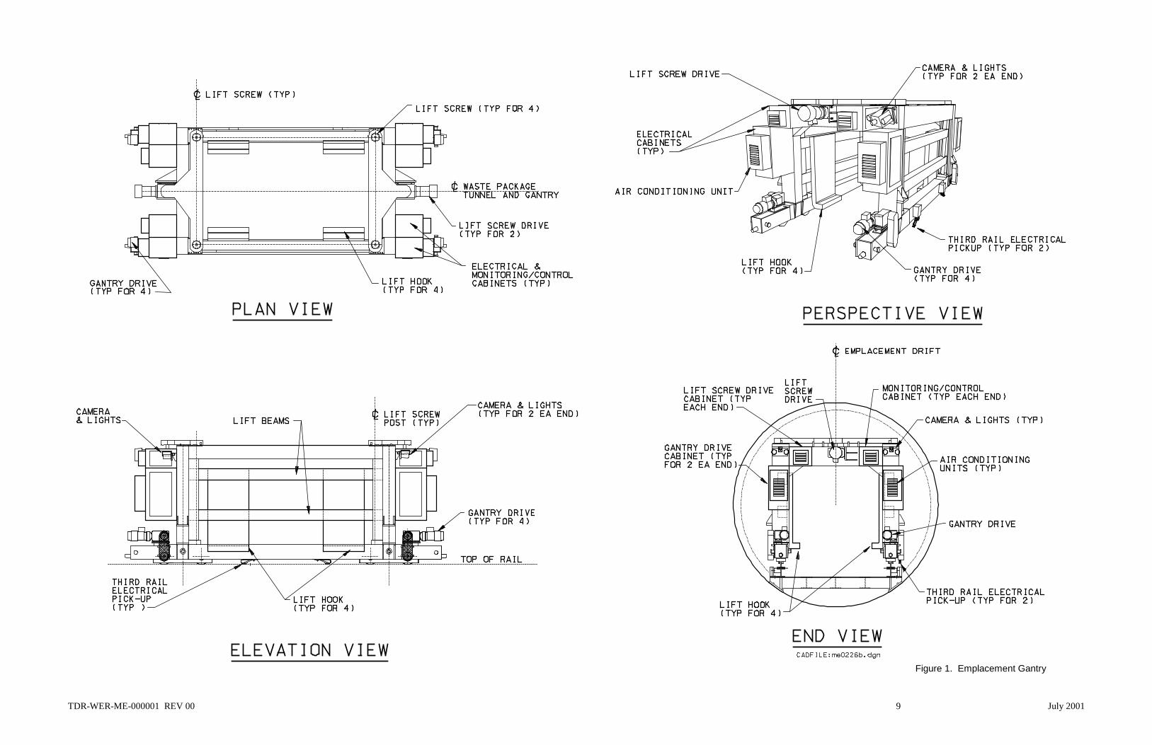
In the current emplacement concept, the emplacement gantry is one of the most critical elementsof the overall design. It is essential that this system perform its intended functions in a safe andreliable manner. The emplacement gantry will be designed to operate in the relatively harshthermal and radiation environment located inside the emplacement drifts. Due to these harshconditions, human operators located at a remote control station will control the operations of thegantry. The basic purpose of the emplacement gantry is to transport the WPs from theemplacement drift dock area, down the length of the emplacement drift, and place them withinthe drift. To support movement and normal retrieval of WPs the emplacement gantry will alsobe capable of reversing these functions.
A preliminary design of the emplacement gantry was recently presented in the design analysisGantry Structural/Control System Analysis (BSC 2001b, entire). The basic mechanicalconfiguration of the emplacement gantry is shown in Figure 1.
It is estimated that up to four emplacement gantries will be used at Yucca Mountain. Multiplegantries can be underground at the same time, performing their function of emplacing the wastepackages. When the emplacement gantries are not in use underground, it is anticipated that theywill be housed in a storage and maintenance facility located on the surface. In this surfacefacility, routine maintenance will be performed on the emplacement gantries to ensure theyremain operational. Large-scale decontamination, that may not be possible in the subsurfaceenvironment, although very unlikely, could also be performed within this facility.
Routine maintenance activities could include: (1) lubrication of ball screws, gear reducers,bearings, etc.; (2) checking motor operation; (3) bogey and drive system maintenance; (4)calibration of instrumentation; and (5) verification of control system operation. These activities
TDR-WER-ME-000001 REV 00 9 July 2001
Figure 1. Emplacement Gantry

TDR-WER-ME-000001 REV 00 10 July 2001
INTENTIONALLY LEFT BLANK

TDR-WER-ME-000001 REV 00 11 July 2001
will be completed on a scheduled basis, determined during the detailed design and fabrication ofthe emplacement gantries.
The maintenance facility will contain a dock and rail system, of appropriate rail gauge, similar tothe docks located at the entrances of the emplacement drifts. This will allow the gantries to beloaded and unloaded to/from the gantry carrier. Movement of the gantries can be accomplishedby using the same wireless methods that will be used in the emplacement drifts or by directlyconnecting a temporary pendant to the control system of the gantry. Once it is determined thatan emplacement gantry is ready for service, it will be moved to the dock and transferred to thegantry carrier. The emplacement gantry carrier is basically a flatbed rail-car device that will beused to shuttle the emplacement gantry from the surface storage and maintenance facility to thedrifts underground. The emplacement gantry carrier will also be used to move the emplacementgantry from one drift to another drift. The transport locomotives will move the gantry carrier.
3.3.1.2 Preparation Of The Waste Package Transporter
The waste package transporter will be a massive rail car that will be used to transport the WPs ina completely enclosed and shielded enclosure from the Waste Handling Building (WHB) at thesurface, down into the emplacement drift area of the potential repository. The waste packagetransporter will be shielded to protect personnel that may need to work in the area through whichthe transporter will travel. A preliminary mechanical design for the waste package transporterwas presented in the Waste Package Transport and Transfer Alternatives design analysis(CRWMS M&O 2000e, section 6) and is shown in Figure 2. In its current design configuration,the shielding used to form the walls, floor, crown and doors of the waste package transporter willbe over 260-mm thick. The shielding will be multiple layers of stainless and carbon steels, and aborated polyethylene material.
The waste package transporter will be equipped with its own set of air brakes and a redundantbackup set of spring-loaded fail-safe brakes. The waste package transporter will have a set ofdouble doors at one end which will be opened and closed by two heavy-duty gear motorsmounted in-line with the axis of the door hinges. Inside the waste package transporter will beWP loading and unloading mechanisms. The loading and unloading mechanisms will consist oftwo main systems: a bedplate and a rigid-chain drive system, which will be used for extendingand retracting the bedplate during loading and unloading activities. Both of these componentsystems will have multiple positioning sensors and other types of performance feedback sensors.Inside the waste package transporter will be a camera system for remote viewing, along withradiation and thermal monitoring instrumentation. An air exhaust system and external radiationmonitor may also be used in the final design of the transporter. This will be used to monitor forairborne contamination inside of the transporter. A positive indication of this would beindicative of either a leaking or contaminated waste package, in which case the transporter wouldbe directed to return to the decontamination facilities located on the surface.
The operation and functions of the WP transporter will be remotely controlled. Controlcommands will originate either from the operator located on the primary locomotive, or they willoriginate from operators located at the remote control room. In either case, the control signalswill be processed by a Programmable Logic Controller (PLC)-based control system located on

TDR-WER-ME-000001 REV 00 12 July 2001
Figure 2. Waste Package Transporter

TDR-WER-ME-000001 REV 00 13 July 2001
INTENTIONALLY LEFT BLANK

TDR-WER-ME-000001 REV 00 14 July 2001
the primary transport locomotive, and then transferred to a PLC-based control system located onthe WP transporter. The PLC-based control system on the WP transporter would then open-close the doors, extract-retract the bedplate, lock the bedplate during transit, and monitor theinterior environment while a WP is present. Interfacing with the surface facilities will thereforebe through the transport locomotive control system. The PLC on the primary locomotive willmonitor and check all operations and system performance parameters of the WP transporter andrelay these signals to operators located at the remote control room.
To meet the peak emplacement rates, it is estimated that there will two or more waste packagetransporters used at Yucca Mountain. When the waste package transporters are not in use, it isanticipated that they will be housed in a storage and maintenance facility located on the surface.In this surface facility, routine maintenance will be performed on the waste package transportersto ensure they remain operational. Decontamination, should it be required, could also beperformed within this facility.
Routine maintenance activities could include: (1) lubrication of unloading mechanism, gearreducers, bearings, etc.; (2) checking door operation and proper sealing; (3) bogey maintenance;and (4) calibration of instrumentation. These activities will be completed on a scheduled basis,determined during the detailed design and fabrication of the waste package transporters.
3.3.1.3 Engagement Of The Transport Locomotives
The transport locomotives will serve as the multi-purpose prime movers of equipment andpersonnel and will be used in almost every aspect of subsurface operations. Duringemplacement operations, the transport locomotives will be used to haul WPs in the wastepackage transporter from the WHB to the entrance of the emplacement drifts. The transportlocomotives will also be used to shuttle the emplacement gantry from drift to drift andperiodically return it to the surface storage and maintenance facility. The transport locomotiveswill also be used to move personnel or materials, as needed, within the subsurface operationsarea.
According to Mobile Waste Handling Support Equipment (CRWMS M&O 1998, section 7.3.1),current concepts for the transport locomotives are based on commercially available mininglocomotives. The estimated weight of the locomotives is currently being reviewed, but should bein the range between 50 to 90 tons. Power for the locomotives will be provided by an overheadtrolley system, and the locomotives will be designed for both direct manual control and wirelessremote control (CRWMS M&O 2000a, section 6.7). The current design layout of the transportlocomotive is shown in Figure 3.
The transport locomotives will engage with either the emplacement gantry carrier or the wastepackage transporter by the use of an automatic coupler. These couplers will join automaticallyand can be released by means of an air cylinder that can be activated from the compressed airsystem on the locomotive. It is envisioned that the automatic couplers will include themechanical coupling as well as all other required utilities such as compressed air, electricalpower, and connections for the control system. Sensors installed in the coupler can transmit

TDR-WER-ME-000001 REV 00 15 July 2001
Figure 3. Transport Locomotive

TDR-WER-ME-000001 REV 00 16 July 2001
INTENTIONALLY LEFT BLANK

TDR-WER-ME-000001 REV 00 17 July 2001
control signals representative of proper engagement to the control system on-board thelocomotive.
The transport locomotive will engage with the emplacement gantry carrier in the surface storageand maintenance facility. The gantry will have to be properly orientated on the carrier so that itcan be readily unloaded into the emplacement drifts underground. The locomotive and gantrycarrier will then travel to the North portal, with the locomotive in the lead position pulling thecarrier.
The transport locomotive will also engage with the waste package transporter in the surfacestorage and maintenance facility. The locomotive will engage to the end of the transporter thathas the shielded enclosure, leaving the open deck end uncoupled. Operation of the transporterfunctions can then be verified. The door could be opened and closed. The bedplate could beextended and retracted. After successful operation of all mechanical functions and verificationof all monitoring signals, the locomotive/transporter could then be considered ready for wastetransport.
3.3.1.4 Loading Of The Waste Package/Pallet Assembly
The locomotive and transporter will then travel to the Waste Handling Building and dock in thearea designed for waste package loading. The door of the transporter will open and the bedplatewill be extended on the open deck. The final operation involved in the preparation of a wastepackage in the Waste Handling Building involves decontamination of the waste package. Thewaste package will be lifted and rotated to a horizontal position and moved by crane to a separatecell for decontamination. Following decontamination, the waste package will be placed on apallet and the waste package/pallet assembly will be positioned on the extended bedplate of thewaste package transporter. Final identification and verification of the waste package placed ontothe transporter will take place at this time. The bedplate of the transporter will retract into theshielded enclosure and the door will close. The locomotive and transporter will then exit theWHB. Because of the relatively high radiation environment surrounding the waste package, allof these operations will be conducted by remote control.
3.3.1.5 Travel Of The Locomotives And Waste Package Transporter To The North Ramp
Outside of the WHB, an operator will get in the cab of the locomotive engaged to the wastepackage transporter and switch the operating mode of the locomotive to local/manual control.The operator will then drive the locomotive to an area that will allow the engagement of a secondlocomotive to the open deck end of the waste package transporter. An on-board operator willalso drive this second locomotive as it is engaged to the transporter by the automatic couplers.Final readings and operability of the two locomotives connected to the transporter will beconfirmed at this time.
Orientation of the WP transporter, prior to entering the repository, is important depending onwhether the designated emplacement drift entrance is off of the East or West main. The opendeck of the WP transporter must ultimately face the drift docking area for successful transfer ofthe WP to the emplacement drift. The WP transporter and locomotives cannot rotate or change

TDR-WER-ME-000001 REV 00 18 July 2001
the orientation of the WP transporter once they enter the subsurface facility. Upon successfullyorienting the WP transporter, the operators then drive the locomotives to the North portal wherefinal readings and inspections can take place.
3.3.1.6 Evaluation of Lower-Temperature Operating Modes on Preparatory SurfaceOperations
All of the operations previously described in section 3.3.1 take place on the surface of theGeologic Repository Operations Area. These operations are the same as the base-case designand the temperature of the operating mode of the repository, should it be lower, will have noimpact on the intended operational concepts.
3.3.2 Preparatory Subsurface Operations
This section of the report discusses the preparatory subsurface operations that will be necessaryto be completed in support of the waste emplacement process. At the end of this section is anevaluation of the effects of operating the repository at a lower-temperature on the intendedconcept of operations.
3.3.2.1 Transfer of Emplacement Gantry from Surface Facilities to an Emplacement Drift
As stated in section 3.3.1.3, the locomotives will engage with the gantry carrier in the surfacestorage and maintenance facility. The emplacement gantry will be suitably positioned on thecarrier for unloading into a designated emplacement drift. An operator in the cab of thelocomotive will then drive the locomotive/carrier assembly to the North portal. The locomotivewill be in the lead position, pulling the carrier.
After appropriate check-in procedures are completed at the North portal entrance, the operatorwill continue to drive the locomotive down the North ramp of the repository. Status andpositional signals will be continuously transmitted to personnel located in the main control roomfor remotely monitoring the operation. Video signals from cameras located along the Northramp will also be transmitted to the main control room. The operator will then drive thelocomotive down the East or West main, depending on the location of the drift entrance.
The operator would drive the locomotive and gantry carrier to an area near the designatedturnout of the emplacement drift to which the gantry is to be unloaded. The operator of thelocomotive would then switch the control system to remote, leave the cab of the locomotive, andmove to a radiation safe area, avoiding all potentially high radiation areas such as the entrance ofthe turnout. Exactly how far away the radiation safe area may be will be determined once finalcalculations can be made regarding the expected dose in the drift turnout with the emplacementdrift isolation doors both open and closed. Once in the radiation safe area, the operator wouldinform personnel in the main control room that it is clear to complete the gantry unloadingoperation. Control of the locomotive would now be from personnel located in the main controlroom.

TDR-WER-ME-000001 REV 00 19 July 2001
The emplacement drift isolation doors would open and the locomotive would slowly push thecarrier into the entrance of the emplacement drift. Video signals along with sensory signalswould be conveyed to the personnel in the main control room to allow them to complete thedocking of the gantry carrier at the dock of the emplacement drift. After alignment and otherappropriate signals signifying correct docking have been received, the gantry would be driven offof the carrier into the emplacement drift under control of operators in the main control room.
Once the gantry is completely off of the carrier, and correct operation is verified, thelocomotive/carrier assembly would travel away from the dock and into the emplacement driftturnout. The emplacement drift isolation doors would then be closed. The locomotive/carrierassembly would then be directed to the main drift. At this time, personnel in the main controlroom would notify the operator in the radiation safe area that it is safe to return to the cab of thelocomotive. The operator would then switch control of the locomotive to manual and resumecontrol of the locomotive/carrier assembly. The locomotive/carrier assembly would then returnto the surface where the carrier would be uncoupled and stored for the next gantry transfer.
3.3.2.2 Transfer of Emplacement Gantry from One Emplacement Drift to AnotherEmplacement Drift or to Surface Facilities
When the gantry has completed emplacement operations in an emplacement drift, ormaintenance is required, or it is determined that WP emplacement should proceed in anotherdrift, it will be necessary to remove the gantry from the emplacement drift it is currently in. Thiscan be accomplished by reversing the steps described in section 3.3.2.1.
An operator would drive the locomotive/carrier assembly to the drift turnout, switch locomotivecontrol to remote, and proceed to a radiation safe area. The emplacement drift isolation doorswould open and the carrier would dock at the entrance of the emplacement drift. The gantrywould be driven onto the deck of the gantry carrier. Once the gantry is properly secured to thecarrier, the locomotive will back away from the dock and into the drift turnout. The isolationdoors would close. The operator would then return to the cab of the locomotive in the main driftand drive the locomotive either to the surface or to the turnout of another emplacement drift. If itgoes to another drift turnout, then the unloading sequence as stated in section 3.3.2.1 will berepeated. If it goes to the surface, appropriate checkout routines will be conducted at the Northportal. If everything is satisfactory, the gantry would be driven to the surface storage andmaintenance facility where storage or required maintenance activities would be conducted.
3.3.2.3 Transport of Personnel and Maintenance Equipment
Maintenance activities need to be periodically performed on the installed equipment located onthe emplacement side of the repository. The rail/invert system, electrical distribution system,lighting system, control/monitoring system, and others require adjustment, lubrication,replacement, and/or calibration over the life of the repository. Transport locomotives coupled toflatbed railcars and/or personnel carriers will be used to assist the maintenance personnel withthese activities. Onboard operators will manually drive the transport locomotive.

TDR-WER-ME-000001 REV 00 20 July 2001
After appropriate check-in procedures are completed at the North portal entrance, the operatorwill continue to drive the locomotive down the North ramp of the repository. Status andpositional signals will be continuously transmitted to the main control room for remotelymonitoring the location of the maintenance crew. Video signals from cameras located along theNorth ramp will also be transmitted to the main control room. Upon completion of the activity,the locomotive and all personnel will return to the North portal where required checkoutprocedures can be completed.
3.3.2.4 Evaluation of Lower-Temperature Operating Modes on Preparatory SubsurfaceOperations
This section of the report will evaluate the five scenarios presented in Sections 3.2.1 through3.2.5 against the operations described in section 3.3.2.
Scenario 1 (Section 3.2.1)—The preparatory subsurface operations take place in the main driftsof the subsurface repository. The main drifts will be maintained to a temperature that will be safefor human occupation as stated in the Subsurface Ventilation System Description Document(CRWMS M&O 2000c, Section 1.2.1.3). This scenario has the same number of waste packagesas the base case design. Since the waste packages will be spaced 2 meters apart, additionalemplacement area will be required to accommodate the emplacement of all packages. The effectthis will have on the emplacement equipment is that the equipment will be required to travellonger distances to reach the turnouts to the emplacement drifts. The impacts of the longerhaulage and travel distances will not be significant during initial emplacement operations.
Because the equipment will travel longer distances, the cycle time for each trip will increaseslightly. Each round trip will take slightly longer, so the equipment will be operating longer. Itis anticipated that the maintenance schedules of the equipment will most likely be based on run-hours. Therefore, the equipment may require additional maintenance activities for the number oftrips it has made. For example, routine maintenance may be conducted every 40 trips for thebase case design. For this scenario, routine maintenance may need to be conducted every 35 or36 trips. The equipment for waste emplacement will be specified later in the program and exactmaintenance impacts can be determined at that time. It is a logical conclusion, though, thatadditional maintenance will be necessary.
Scenario 2 (Section 3.2.2)— This scenario has more waste packages than the base case design.Even though the waste packages will be spaced 0.1 meters apart, additional emplacement areawill be required to accommodate the additional quantity of waste packages. The effect this willhave on the emplacement equipment is that the equipment will be required to make additionaltrips and travel longer distances to reach the turnouts to the emplacement drifts. The impacts ofthe longer haulage and travel distances will not be significant during initial emplacementoperations.
Similar to scenario 1, the equipment will most likely require additional maintenance activities forthe number of trips it has made. For example, routine maintenance may be conducted every 40trips for the base case design. For this scenario, routine maintenance may need to be conducted

TDR-WER-ME-000001 REV 00 21 July 2001
every 35 or 36 trips. This scenario will also have more trips than scenario 1, so the maintenancerequirements will most likely be more than scenario 1.
Scenario 3 (Section 3.2.3)—This scenario is very similar to scenario 1 except the waste packagespacing is three times larger (6 m) and the emplacement area is 55 percent more. Traveldistances per trip will increase significantly, as will the equipment maintenance requirements.The maintenance activities for this scenario will most likely be more than scenario 1, and equalto or greater than that anticipated for scenario 2.
Scenario 4 (Section 3.2.4)—This scenario is similar to scenario 1. It is therefore anticipated thatthis scenario will have the same amount of additional maintenance requirements as scenario 1.
Scenario 5 (Section 3.2.5)—This scenario is functionally identical to the base case, and thereforeit is anticipated that there will be no effect on the operational concepts.
3.3.3 Waste Transport Operations
This section of the report describes the operation of moving the WPs from the surface facilities,specifically the North portal, to the entrance of the designated emplacement drift. At the end ofthis section is an evaluation of the effects of operating the repository at a lower-temperature onthe intended concept of operations.
3.3.3.1 Locomotive and WP Transporter Travel through the Main Drifts
After final check-in procedures are completed at the North portal entrance, the WP transporter,sandwiched between two locomotives, will begin travel down the North ramp. Figure 4 depictsthe leading locomotive, trailing locomotive, and WP transporter. Status and positional signalswill be continuously transmitted to the main control room for remotely monitoring the operation.The operators located in the locomotive cabs will control the locomotives. An overridecapability will be available to allow the operators located in the main control room to assumecontrol of the locomotives, should such a condition arise. Video signals from cameras locatedalong the North ramp will also be transmitted to the main control room. The operators will thendrive the locomotives down the East or West main, depending on the location of the designatedemplacement drift.
3.3.3.2 Locomotive and WP Transporter Arrival at Emplacement Drift
In the East or West main, at a location near the designated drift turnout, the locomotives and WPtransporter will come to a stop. The locomotive coupled to the open deck end of the WPtransporter will then uncouple from the assembly and move away from the WP transporter. Theoperator of the locomotive still coupled to the WP transporter would then switch the controlsystem to remote, leave the cab of the locomotive, and move to a radiation safe area, avoiding allpotentially high radiation areas such as the entrance of the turnout and the WP transporter.Exactly how far away the radiation safe area may be will be determined once final calculationscan be made regarding the WP transporter shielding, locomotive shielding, and the expecteddose in the drift turnout with the emplacement drift isolation doors both open and closed. Once

Figure 4. Tandem Locomotives Transporting the Waste Package Transporter
TDR
-WER
-ME-000001 R
EV 00
22July 2001

TDR-WER-ME-000001 REV 00 23 July 2001
in the radiation safe area, the operators can inform personnel in the main control room that it isclear to complete the WP transporter docking operation. Control of the locomotive coupled tothe WP transporter would now be from personnel located in the main control room.
3.3.3.3 Locomotive and WP Transporter Docking at Emplacement Drift
The locomotive, under remote control, pushes the WP transporter, with the open deck endleading, into the emplacement drift turnout to a point outside the isolation doors and stops. Theemplacement drift isolation doors and the WP transporter doors would open. Once the operatorsin the main control room receive verification that all doors are completely open, the locomotivewould slowly push the WP transporter into the entrance of the emplacement drift. Video signalsalong with sensory signals would be conveyed to the personnel in the main control room to allowthem to safely complete the docking of the WP transporter at the dock of the emplacement driftas shown in Figure 5. After alignment and other appropriate signals signifying correct dockinghave been received, the locomotive would be put in a parked mode.
If all conditions are satisfactory, the bedplate with the WP and pallet assembly will extend fromthe shielded enclosure out onto the open deck. Appropriate sensory and visual equipment will beinstalled to inform the operators in the main control room that the WP and pallet assembly isready to be removed from the WP transporter.
3.3.3.4 WP Transporter Return to Surface
After the WP and pallet assembly has been removed from the extended bedplate of the WPtransporter, the locomotive will back out of the dock at the entrance of the emplacement drift.Once the locomotive is sufficiently clear of the isolation doors it will stop in the emplacementdrift turnout. The bedplate would retract into the shielded enclosure and the isolation doors andWP transporter doors would close. The operators in the main control room, having receivedverification that all doors are closed, would then direct the locomotive to the main drift. Theoperators, in the radiation safe area, would be notified that it is safe to return to the area outsidethe emplacement drift. The second locomotive would couple to the open deck end of the WPtransporter. The operators, in the cabs of both locomotives, would then drive the WP transporterback up to the surface facilities.
3.3.3.5 Evaluation of Lower-Temperature Operating Modes on Waste TransportOperations
The waste transport operations will take place in the main drifts of the subsurface repository.The main drifts will be maintained to a temperature that will be safe for human occupation asstated in the Subsurface Ventilation System Description Document (CRWMS M&O 2000c,Section 1.2.1.3). The operations presented in this section are very similar to those discussed inSection 3.3.2. The effects of a lower-temperature repository on the waste transport operationswill be the same as those presented in Section 3.3.2.4. The major impact is that with a largeremplacement area, the equipment may require additional maintenance because of the longerdistances and extended travel times that the equipment must endure as compared to the base casedesign.

Figure 5. Waste Package Transporter Docked at Emplacement Drift Entrance
TDR
-WER
-ME-000001 R
EV 00
24July 2001
TDR-WER-ME-000001 REV 00 25 July 2001
3.3.4 Waste Emplacement Operations
This section of the report describes the operation of moving the WPs from the entrance of thedesignated emplacement drift to its final placement within the drift.
3.3.4.1 Emplacement Gantry Engagement of WP and Pallet Assembly
After the WP and pallet assembly is extended on the bedplate of the WP transporter at theemplacement drift dock, the emplacement gantry will be instructed to move over the WP andpallet, straddling the WP transporters open deck. The lift hooks will be in the lowest positionallowing them to move under the pallet. Control of the gantry will be by operating personnellocated in the main control room. After successful positioning of the gantry, the drive motorswill be put in the locked or parked position and the lift hooks will raise the WP and pallet off ofthe WP transporter bedplate. Once sufficiently raised, the lift hook hoist motors will be put inthe locked or parked position. The drive motors will be unlocked and the gantry, with the WPand pallet assembly, will then be driven down the emplacement drift as shown in Figure 6. TheWP transporter would not be allowed to leave the dock area until the gantry has moved the WPand pallet assembly clear of the WP transporter through the use of administrative and mechanicalcontrols.
3.3.4.2 Emplacement Gantry Travel within Emplacement Drift
The gantry will be equipped with visual and other sensory equipment to allow the operatorsremotely controlling it to know its position within the emplacement drift at all times. The gantrywill have a “home” position that will be a short distance into the emplacement drift. It is fromthis home position that all movement of the gantry will originate. After the gantry has lifted theWP and pallet assembly to clear all obstructions, it will move to the home position. The WPtransporter will leave the emplacement drift dock area and the drift isolation doors will close.
Once the emplacement drift isolation doors have been verified in the closed position, the gantrywill then be allowed to leave the home position. The base-case repository design consists of lineloading the emplacement drifts. This equates to a 10 centimeter spacing between waste packagesas they are permanently placed within the emplacement drift. The gantry will then travel theappropriate distance down the emplacement drift to place the WP and pallet assembly 10centimeters from the previously installed WP. Should the WP be the first one to be installed inthe drift, permanent markings or other means will be used so the operators can remotely positionthe gantry at the correct location to set the WP.
3.3.4.3 Placement of WP within Emplacement Drift
Once the gantry has been verified to be in the correct position to place the WP, the drive motorswill be put into the locked or parked position. The lift hook hoist motors will be released fromtheir parked position and they will lower the WP and pallet assembly onto the invert of theemplacement drift. Measurements of the WP spacing would then be made. If a modification tothe WP placement is deemed to be necessary, the hoist motors would lift the WP and pallet, thegantry drive motors would creep in the appropriate direction and the WP and pallet would be re-

Figure 6. Emplacement Gantry Transporting a Waste Package in the Emplacement Drift
TDR
-WER
-ME-000001 R
EV 00
26July 2001

TDR-WER-ME-000001 REV 00 27 July 2001
lowered onto the drift invert. The process would be repeated until the placement of the WP iswithin acceptable limits. Final readings of the WP’s placement would then be taken andrecorded in the database for future use. After acceptable final placement, the gantry, with the lifthooks in the lowered position, would then be directed to the home position where it would be putin the parked position to await further operating instructions.
3.3.4.4 Evaluation of Lower-Temperature Operating Modes on Waste EmplacementOperations
This section of the report evaluates the five scenarios presented in Sections 3.2.1 through 3.2.5against the operations described in section 3.3.4. At the end of this section is an evaluation ofthe effects of operating the repository at a lower-temperature on the intended concept ofoperations.
Scenario 1 (Section 3.2.1)—This scenario has the same quantity of waste packages as the basecase design. Waste emplacement operations will all take place within the emplacement drifts.The Subsurface Ventilation System Description Document states that temperatures within theemplacement drifts shall be maintained to a maximum of 50 °C (CRWMS M&O 2000c, Section1.2.1.4) during emplacement operations. The waste emplacement operations, for this scenario,will be the same as the base-case design and the temperature of the operating mode of therepository, should it be lower, will have no impact on the intended operational concepts.
Scenario 2 (Section 3.2.2)—This operating scenario will have more waste packages to emplacethan the base case design. As in scenario 1, temperatures within the drift will be maintained to amaximum of 50 °C. Because of the additional amount of waste packages, the emplacementgantry will be required to operate for a longer period of time. This extended period of operationwould require additional maintenance and possible replacement of the emplacement gantry.
Scenario 3 (Section 3.2.3)—This scenario has the same quantity of waste packages as the basecase design. The waste emplacement operations, for this scenario, will be the same as the base-case design and the temperature of the operating mode of the repository, should it be lower, willhave no impact on the intended operational concepts
Scenario 4 (Section 3.2.4)—This scenario has the same quantity of waste packages as the basecase design. The waste emplacement operations, for this scenario, will be the same as the base-case design and the temperature of the operating mode of the repository, should it be lower, willhave no impact on the intended operational concepts
Scenario 5 (Section 3.2.5)—This scenario has the same quantity of waste packages as the basecase design. The waste emplacement operations, for this scenario, will be the same as the base-case design and the temperature of the operating mode of the repository, should it be lower, willhave no impact on the intended operational concepts.

TDR-WER-ME-000001 REV 00 28 July 2001
3.3.5 Waste Movement Operations
This section of the report describes the operation of relocating a WP from one emplacement driftto another emplacement drift located within the subsurface facilities.
3.3.5.1 Removing a WP From an Emplacement Drift
To facilitate the relocation of a WP, the emplacement gantry will need to be unloaded into theemplacement drift that contains the particular WP to be relocated. This unloading operation ofthe emplacement gantry will be as stated in Section 3.3.2.1. The emplacement gantry will travelto the home position within the drift and wait until the WP transporter is docked at the entranceof the emplacement drift. The docking of the WP transporter will be as described in Section3.3.3.3. Upon verification that the WP transporter is successfully docked, the emplacementgantry, with the lift hooks in the lowered position, will then travel down the drift until the firstWP is encountered.
Once the gantry has been verified to be in the correct position to raise the WP, the drive motorswill be put into the locked or parked position. The lift hook hoist motors will be released fromtheir parked position and they will raise the WP and pallet assembly off the invert of theemplacement drift. Once the WP and pallet assembly has been sufficiently raised, the lift hookmotors will be put into their locked position and the drive motors will be released. The gantrywill then travel to the entrance of the emplacement drift and suitably position itself over theextended bedplate of the WP transporter. Once the gantry has been verified to be in the correctposition to lower the WP, the drive motors will be put into the locked or parked position. The lifthook hoist motors will be released from their parked position and they will lower the WP andpallet assembly onto the extended bedplate of the WP transporter.
The gantry will then move to its home position within the emplacement drift, the bedplate of theWP transporter will retract into the shielded enclosure, the transport locomotive will pull the WPtransporter away from the dock of the emplacement drift, and all doors (WP transporter and driftisolation) will close.
3.3.5.2 Travel of WP Transporter to Another Emplacement Drift
Under remote control by the operators located in the main control room, the transport locomotiveand WP transporter will be directed to the main drift. The operator will then return from theradiation safe area and enter the cab of the locomotive coupled to the WP transporter. Thesecond transport locomotive may couple to the open deck end of the WP transporter at this time,depending on the location of designated emplacement drift for movement of the WP. If thedesignated drift is off the same main drift, a short distance away, only one transport locomotivemay be used. If the designated drift entrance is off the other main drift (East going to West orWest going to East), the second locomotive will couple to the WP transporter and the assemblywill travel to the surface. This action is necessary to properly orient the WP transporter for WPunloading. The open deck of the WP transporter must ultimately face the drift docking area forsuccessful transfer of the WP to the emplacement drift. Transport locomotive and WPtransporter travel through the main drifts will be as discussed in Section 3.3.3.1.

TDR-WER-ME-000001 REV 00 29 July 2001
3.3.5.3 Unloading the WP at the Different Emplacement Drift
Unloading a WP at a different emplacement drift will consist of the same operations as initialWP transport and emplacement. These operations are described in Sections 3.3.3 and 3.3.4 ofthis report.
3.3.5.4 Evaluation of Lower-Temperature Operating Modes on Waste MovementOperations
The waste movement operations will consist of the same operations as those discussed inSections 3.3.3 and 3.3.4 of this report. The effects of a lower-temperature repository on thewaste movement operations will therefore be the same as those presented in Sections 3.3.3.5 and3.3.4.4. The major impact is that with a larger emplacement area, the equipment may requireadditional maintenance because of the longer distances and extended travel times that theequipment must endure as compared to the base case design.
3.3.6 Waste Retrieval Operations
This section of the report describes the operation of retrieving the WPs from the emplacementdrifts to facilities located on the surface.
3.3.6.1 Purpose of Waste Retrieval
The capability to retrieve all or part of the emplaced high-level nuclear waste is required by lawand NRC licensing requirements (NRC 1998, Section 63.111). The design approach to satisfythe retrievability requirement is that nothing in the repository design or in the emplacementprocedures shall preclude the retrieval of any or all of the waste packages. While the capabilityto retrieve the waste packages is a licensing requirement, it will not unduly control the repositorydesign and waste emplacement operations.
There can be two reasons for retrieving all or part of the nuclear waste emplaced at therepository. The first reason is because it has been determined that failure in the site, the wastepackage, or some other system is causing a possible risk to the public health, waste isolation, orthe environment. The second reason is because the DOE has determined that recovery ofvaluable resources is possible from the emplaced spent nuclear fuel. The need to retrieve will becaused by a change in DOE policy and not by an event or condition known to exist at the time ofrepository approval to accept spent nuclear fuel.
3.3.6.2 Normal Retrieval Conditions and Operations
Normal retrieval would occur based on the reasons stated above. Conditions within therepository during preclosure would be as expected with no leakage or contamination from anywaste package detected. All significant systems, structures, and components that make up thesubsurface facility would be operating normally and capable of performing their intendedfunctions. The operational concepts for retrieving the waste packages under normal conditions

TDR-WER-ME-000001 REV 00 30 July 2001
would be exactly opposite those executed in the waste emplacement process. The normalretrieval sequence of operations is summarized below:
1. The locomotive and gantry carrier w/gantry travel to the emplacement drift.
2. The drift isolation doors would open.
3. The locomotive and carrier docks at the entrance of the emplacement drift.
4. The gantry moves off of the carrier and the locomotive and carrier leave the area and the driftisolation doors close.
5. The gantry moves to the location of the nearest WP, which will be closest to the driftentrance, engages the pallet assembly, and raises the WP and pallet.
6. The transport locomotives and empty WP transporter travel to the main drift just outside theturnout to the emplacement drift.
7. The secondary locomotive uncouples and the primary locomotive pushes the WP transporterinto the drift turnout, all doors open, and the WP transporter docks at the emplacement driftentrance.
8. The bedplate of the WP transporter extends out onto the open deck.
9. The gantry moves over the open deck of the WP transporter and lowers the WP and palletassembly onto the extended bedplate.
10. The bedplate retracts into the shielded enclosure of the WP transporter.
11. The primary locomotive then moves the WP transporter from the dock, into the drift turnout,all doors close, and then the WP transporter moves into the main drift.
12. The secondary locomotive couples to the WP transporter and the train travels to the surfacefacilities.
Retrieved WPs that are in good condition will be taken to the surface and staged in a dedicatedarea within the surface facilities complex. The surface facilities complex for retrieved WPs willhave appropriate unloading mechanisms to remove the WP/pallet assembly from the bedplate ofthe WP transporter. It is anticipated that these unloading mechanisms will be similar to thoseused to load the WP transporter as stated in Section 3.3.1.4. If a damaged WP or a driftcondition preventing normal retrieval is encountered, the sequence will be interrupted, andcontingency plans for abnormal retrieval, discussed in section 3.3.6.3, will be implemented.

TDR-WER-ME-000001 REV 00 31 July 2001
3.3.6.3 Abnormal Retrieval Conditions and Operations
Abnormal retrieval conditions result when one or more abnormal events occur before or duringwaste emplacement, caretaking, or normal retrieval operations. Abnormal events may be theresult of an unexpected or unplanned process occurring within the repository that would hindernormal operation. An abnormal event refers to subsurface conditions that have deviated or beendisturbed in some way to prevent normal operation.
The basic strategy for the mitigation of all abnormal conditions will consist of the followingactivities:
• Assessing nuclear and non-nuclear safety• Establishing access control and isolation of the event area from continued operations, if
required• Confining radioactive contamination, if present• Collecting critical technical data, other than nuclear• Formulating a mitigation plan• Designing and providing any additional specialized equipment needed for mitigation• Implementation of the mitigation plan
This report discusses operational concepts for three worst case abnormal events consisting of (1)an emplacement gantry derailment within the emplacement drift, (2) a rock fall or groundsupport failure within the emplacement drift, and (3) retrieval of contaminated or breached wastepackages. There are numerous abnormal conditions that could occur during the preclosureperiod of the repository leading to abnormal retrieval operations. The discussion andidentification of all possible abnormal events and retrieval scenarios such as a collapsed WPpallet, fire, emplacement equipment failure, drift isolation door failure, rail switch failure orother system failure is considered outside the scope of this report.
3.3.6.3.1 Derailment of Emplacement Gantry
The purpose of this section is to discuss a recovery concept for an abnormal condition that dealswith a derailed or otherwise immobilized gantry within an emplacement drift. At the time of thederailment, the gantry may be with or without the load of a WP/pallet assembly.
To accommodate working in an emplacement drift under abnormal conditions, two pieces ofretrieval equipment were presented and discussed in the Retrieval Equipment and Strategy forWP on Pallet analysis (CRWMS M&O 2000b, Section 6.2.4). These were:
• Emplacement Drift Gantry Carrier, shown in Figure 7 (CRWMS M&O 2000b,Section 6.2.4)
• Multipurpose Hauler, shown in Figure 8 (CRWMS M&O 2000b, Section 6.2.4)
Both pieces of equipment have been conceived to operate on steel rollers and temporary steelplates, which would need to be placed on the invert system between the gantry rails. The

TDR
-WER
-ME-000001 R
EV 00
32July 2001 Figure 7. Emplacement Gantry Carrier

TDR
-WER
-ME-000001 R
EV 00
33July 2001
Figure 8. Multipurpose Hauler

TDR-WER-ME-000001 REV 00 34 July 2001
multipurpose hauler could perform the installation of the steel plates on top of the steel invertand ballast within the emplacement drift. These plates will allow the emplacement drift gantrycarrier and multipurpose vehicle to operate as intended (CRWMS M&O 2000b, Section 6.2.4).
There are two major alternatives for the rerailment of a derailed emplacement gantry:
• The use of rerailers• The use of an emplacement drift gantry carrier
Use of rerailers–As the name suggests, a typical rerailer is a portable device designed to rerail arailcar that has come off its track. When two rerailers, one on each side of the tracks, areinstalled, the disabled railcar is then pulled over the rerailers. The shape and design of thererailers lift and align the wheels of the railcar with the rail-head, as the wheels are being rolledover the rerailer, thereby putting the railcar back on the track. As a single piece of equipmentwithout any moving parts, a rerailer provides a simple and reliable means to rerail a railcar thathas come off of the track.
Adverse conditions, such as high temperatures, high radiation and limited space, may make theremote installation and alignment of rerailers difficult. Additional factors that could inhibit theuse of rerailers may include:
• Excessive weight of the gantry with a WP/pallet assembly,• Position of the emplacement gantry off of the track/rail system.
Use of an emplacement drift gantry carrier–If it is determined that the use of rerailers is not aviable option for the recovery of a derailed emplacement gantry, a second option will have to beutilized. This retrieval option would involve the use of an emplacement drift gantry carrier,which has been conceptually developed to recover a derailed, or otherwise disabled,emplacement gantry within the confines of the emplacement drift envelope. This specializedequipment will be designed to perform the following operations:
• Move and position itself underneath the unloaded emplacement gantry,• Raise the emplacement gantry above the level of the gantry track,• Align the emplacement gantry wheels with the track,• Lower the emplacement gantry back onto the track, or completely haul the emplacement
gantry out of the emplacement drift.
The following paragraphs describe a potential gantry derailment scenario and the mitigationstrategy for the recovery of the derailed emplacement gantry, which happened to be carrying aWP/pallet assembly.
Gantry Derailment Scenario–Assume that the gantry derailment occurs deep within theemplacement drift, near the ventilation raise. As a result of the derailment, the emplacementdrift rails under the derailed gantry are damaged beyond use, and the gantry trucks on theventilation-raise-side are inoperable (i.e., the gantry will no longer roll). In addition, the electricthird rail near the gantry is damaged, thus eliminating the electric power supply to the

TDR-WER-ME-000001 REV 00 35 July 2001
emplacement gantry. The use of rerailers would not be a feasible option for the mitigation of thisscenario due to the damaged rail, gantry trucks and electric third rail.
A possible mitigation sequence may be as follows:
Mitigation Plan Development–Because the emplacement gantry trucks closest to the ventilationraise are damaged, these trucks must be raised off the invert and the gantry towed out of theemplacement drift. In the formulation of the mitigation plan, it was determined that access to thederailed emplacement gantry would be from the rear of the emplacement drift, through the driftentrance on the other side of the repository. Gaining access would be accomplished by removingthe WPs from the far end of the emplacement drift and any that would be in the drift sectionbetween the ventilation raise and the disabled gantry.
WP Removal–WPs that may be limiting access to the disabled gantry would be removed undernormal retrieval operations, described in Section 3.3.6.2, using a second emplacement gantry.After all WPs up to the ventilation raise have been removed from the drift, the multipurposehauler, carrying the multipurpose vehicle, will enter the drift from the other end. To make itpossible for the retrieval equipment to travel across the ventilation raise, the remotely controlledmultipurpose vehicle would utilize its grippers to remove the elevated collar on the ventilationraise and the stop blocks installed at the ends of the gantry rails. While performing thesefunctions, the multipurpose vehicle would operate from the deck of the multipurpose hauler asshown in Figure 9. An emplacement drift retrieval locomotive would provide the locomotivepower to move the multipurpose hauler carrying the multipurpose vehicle. The location of theventilation raise is currently being reviewed. It may be possible to locate the raise in an alcoveoff the emplacement drift that would allow rail to run continuously from one emplacement driftentrance to the other. The exhaust main could also be located above the emplacement drifts sothe raise would be located off the top of the emplacement drifts. This approach would also allowrail to be run continuously from one drift entrance to the other. This report will discuss the worstcase scenario, which is having the ventilation raise in the center of the emplacement drift, withthe exhaust main located below the emplacement drift elevation.
The multipurpose vehicle will be a relatively small unit designed to remotely operate in theemplacement drifts, main drifts, and ramp areas, either on the drift inverts or from the deck of themultipurpose hauler. The multipurpose vehicle can be fitted with various attachments, eachintended to perform a specific function. Such attachments include, but are not limited to, abucket attachment for removing debris, an impact hammer for reducing debris size, a cuttingtorch to dismantle damaged equipment or structures, and grippers to remove or install requiredpieces of retrieval equipment.

TDR
-WER
-ME-000001 R
EV 00
36July 2001
Figure 9. Multipurpose Hauler Removing Obstructions

TDR-WER-ME-000001 REV 00 37 July 2001
After removal of the ventilation raise collar, the multipurpose vehicle will install grating, rail,and necessary supports so that equipment can gain access to the derailed emplacement gantry.Once rail integrity has been verified across the ventilation raise, the retrieval locomotive,multipurpose hauler, and multipurpose vehicle will exit the drift from the far end. The secondemplacement gantry would again enter the drift and remove the remaining WP/pallet assembliesup to the derailed emplacement gantry as shown in Figure 10. Due to the lack of available third-rail electric power across the ventilation raise, the retrieval locomotive, with on-board batteries,would power or provide the locomotive force to the emplacement gantry and any otherequipment not having self-contained power sources.
Removal of the WPs downstream of the ventilation raise is envisioned as follows. The retrievallocomotive would push or power the emplacement gantry as it travels across the raise towardsthe WPs. The emplacement gantry would then engage the nearest WP/pallet assembly and raiseit. Once all necessary interlocks have been satisfied, the retrieval locomotive would pull orpower the emplacement gantry as it travels across the raise towards the drift entrance on theother side of the repository. When sufficiently clear of the ventilation raise, and power has beenverified to the emplacement gantry, the retrieval locomotive will disengage from theemplacement gantry. The retrieval locomotive would then travel to the drift entrance, ahead ofthe emplacement gantry, and be taken away by a carrier similar to the emplacement gantrycarrier. The WP transporter would then dock at the drift entrance. The gantry would move intoposition over the WP transporter and lower the WP/pallet assembly onto the bedplate. Thebedplate would retract and the WP transporter would then travel to another drift or to facilities onthe surface. The retrieval locomotive would be installed in the drift and the process would berepeated until all WPs limiting access to the derailed emplacement gantry have been removed
Removal of WP/pallet Assembly–When all of the WPs have been removed from the drift, theemplacement gantry and retrieval locomotive will be removed from the drift and themultipurpose hauler, multipurpose vehicle, and retrieval locomotive will enter the drift. The nextstep toward completing the recovery operations would be to remove the WP/pallet assemblyfrom the derailed gantry. The multipurpose vehicle on the multipurpose hauler could restorepower to the derailed gantry by connecting an electrical power and data communications cable toauxiliary receptacles on the disabled emplacement gantry. The multipurpose vehicle wouldplace steel plate onto the invert surface underneath the gantry to form an elevated sliding surface.The lifting mechanism on the disabled gantry would then lower the WP/pallet assembly onto thissteel plate.
The multipurpose hauler carrying the multipurpose vehicle will then travel to the drift entrancewhere the multipurpose vehicle will be removed. The multipurpose hauler would be sent backinto the emplacement drift and travel to the disabled gantry. The winch cable on the haulerwould be attached to the lower section of the pallet frame that supports the WP using themanipulator arm, and the WP/pallet assembly would be pulled onto the deck of the hauler asshown in Figure 11. Some slipping of the multipurpose hauler may occur during the winchoperation. However, any slipping that may occur is insignificant to the design or operation of thehauler and would not preclude the hauler from retrieving the WP/pallet assembly. After therecovery of the WP/pallet assembly, the multipurpose hauler would be transported to the driftentrance for removal on an emplacement gantry carrier or equivalent type of transport vehicle.

TDR
-WER
-ME-000001 R
EV 00
38July 2001
Figure 10. Second Gantry Removing WP
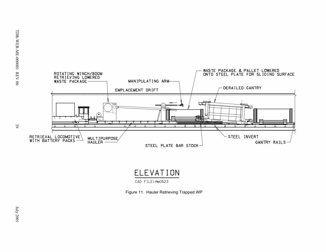
TDR
-WER
-ME-000001 R
EV 00
39July 2001
Figure 11. Hauler Retrieving Trapped WP

TDR-WER-ME-000001 REV 00 40 July 2001
In the event of a breached WP, the multipurpose hauler could be equipped to accept a temporarycontamination enclosure (see Figure 8). Due to limited workspace within the emplacement drift,the enclosure would have to be installed within the drift turnout once the hauler was clear of theemplacement drift.
The enclosure on the multipurpose hauler would be maintained under a negative pressure (i.e., avacuum), with a blower exhausting into a High-Efficiency Particulate Air (HEPA) filter(CRWMS M&O 2000b, Section 6.2.4). The enclosure would contain any airborne contaminationparticles emanating from the WP, but it would not provide any radiation shielding. Due to thiscondition, personnel access would have to be restricted to areas at a safe distance from the WPduring transport from the subsurface areas to the surface facilities.
After the release and removal of the WP/pallet assembly from within the emplacement drift, thegantry lifting mechanism would be raised to an elevated position to allow free access to theunderside of the derailed gantry. The following paragraphs provide details for the preparationand removal of the derailed emplacement gantry.
Removal of Derailed Gantry–To provide the emplacement drift gantry carrier with an evenrolling surface, steel plates would be set by the multipurpose vehicle onto the invert, between theemplacement drift rails. The emplacement drift gantry carrier would be carried into the drift andplaced on the steel plates by a second emplacement gantry. A retrieval locomotive would thenpush the emplacement drift gantry carrier into place under the derailed gantry as shown in Figure12. Stabilizer pads on the emplacement drift gantry carrier would be extended to contact thedrift invert and provide the necessary stability while the vertical ball screw jacks on theemplacement drift gantry carrier contact the gantry frame from underneath and attempt to raise itabove the gantry rail.
If lifting of the gantry were not possible due to ground support interference, the horizontal ballscrew jacks on the emplacement drift gantry carrier would be deployed, shifting the gantrytowards the gantry rail. The derailed gantry, now clear of the ground support interference, wouldthen be raised just above the damaged tracks, and pulled to an area where good track rail exists.
Once the gantry is aligned with the good rail track, two possible scenarios to recover the gantryfrom within the emplacement drift exist. These scenarios would depend on the severity of thegantry derailment.
If the gantry can be re-railed by the emplacement drift gantry carrier, as described above, and thegantry remains functional, i.e., the drive system and controls remain in working condition, thegantry would travel under its own power to the emplacement drift entrance. At the entrance, thegantry would board the gantry carrier, not to be confused with the emplacement drift gantrycarrier, and be moved to the surface maintenance and storage facility for repair.

TDR
-WER
-ME-000001 R
EV 00
41July 2001
Figure 12. Emplacement Drift Gantry Carrier Pushed into Position

TDR-WER-ME-000001 REV 00 42 July 2001
However, if the gantry trucks, drive mechanism, and/or control system have been severelydamaged and are no longer functional, the emplacement drift gantry carrier would then be usedto transport the emplacement gantry to the emplacement drift entrance. The emplacement driftgantry carrier, moved by a retrieval locomotive, would raise the gantry off the rail and tow thegantry to the emplacement drift entrance as shown in Figure 13.
The above discussion is definitely a worst case scenario. Gaining access to a disabled gantryfrom the other entrance to an emplacement drift does introduce a number of challengingoperations, which while difficult, are not impossible. It is anticipated that any derailments couldbe dealt with operations conducted from the same drift entrance so travel across the ventilationraise, should there be one, will not be required. Operations conducted from the same driftentrance will not require the removal of any emplaced WPs, which should significantly reducethe total amount of time to correct the situation.
3.3.6.3.2 Rock fall or Ground Support Failure
A rock fall or ground support collapse within an emplacement drift will require an abnormalretrieval activity to be executed if it is determined that the WP/pallet assemblies should beremoved from the damaged drift. Another emplacement gantry or mobile piece of surveyingequipment could be used to inspect the emplacement drift after the rock fall was observed. Itemsto be surveyed would include the amount of rock in the emplacement drift, the presence ofradionuclide contamination, the position of any equipment (if involved), condition of the groundsupport, and the condition of the drift invert and gantry tracks.
Ground Support Failure Scenario–One example scenario would be if a portion of the groundsupport fails within an emplacement drift causing a blockage within the drift. To make thescenario more severe, it can be envisioned that WP emplacement has begun, WPs are present,and a loaded emplacement gantry is in the area of the rock fall and becomes partially buried asshown in Figure 14. In addition, repository infrastructure components, including the groundsupport, rail tracks, electric third rail, and communication systems are severely damaged andinoperable downstream of the area of the rock fall. Data communication and associated videosignals from the emplacement gantry would be lost, putting the remote operators in a totalblackout condition.
A remote inspection vehicle, possibly the one intended to obtain performance confirmation data,would be sent into the drift to survey the damage. The remote inspection vehicle would betransported to the drift entrance on the gantry carrier and docking and unloading operationswould be the same as those discussed in section 3.3.2.1. Video signals of the rock fall andsurrounding damage would then be transmitted to the main control room. Sensory equipmentwould also transmit data representative of the environmental conditions in the drift. Thesesignals could include ambient temperature, radiation levels, amount of airflow, humidity, andgases of interest, such as carbon monoxide, or tracer gases if such are used in the fabrication ofthe WP.

TDR
-WER
-ME-000001 R
EV 00
43July 2001
Figure 13. Emplacement Drift Gantry Carrier Moving Derailed Gantry

TDR
-WER
-ME-000001 R
EV 00
44July 2001
Figure 14. Rock Fall in Emplacement Drift Partially Covering Equipment

TDR-WER-ME-000001 REV 00 45 July 2001
A specialized investigative team would interpret the data and video signals transmitted by theremote inspection vehicle and develop a mitigation plan. For the above scenario the mitigationplan could include the following steps.
Mitigation Plan Development–Ventilation was severely interrupted by the drift/ground supportcollapse that occurred in the loaded drift midway between the emplacement drift entrance andthe ventilation raise, and some form of temporary ventilation is required to cool the disabledportion of the drift. Without the temporary ventilation, the drift temperature would rise abovepredetermined operational limits for the retrieval equipment. A possible mitigation plan coulddetermine that to provide the pathway for the temporary ventilation, an emergency ventilationairway could be bored from an adjacent drift to the damaged drift.
WP Removal–To implement the recovery operations of the conceptual mitigation plan, allWP/pallet assemblies of the adjacent drift would need to be removed. This would beaccomplished using the normal retrieval operational concepts as discussed in Section 3.3.6.2.The removal of all WP/pallet assemblies would then provide access for personnel and miningequipment so a tunnel could be constructed to the disabled drift. A roadheader, drill-and-blast,and/or other mining equipment and techniques would be used in the construction of theemergency ventilation airway.
Prior to the start of any tunneling activity, the WP/pallet assemblies located in the damaged driftbut outside the rock fall area would be removed using normal retrieval procedures, as describedin Section 3.3.6.2. These WP/pallet assemblies would likely be located downstream of theventilation raise and access to them would be from the other side of the emplacement drift. TheWP/pallet assemblies retrieved under these conditions would be those that are undisturbed, notburied by rock fall, and where the electric power supply and control system is still in workingorder. The mobile equipment for this operation would consist of the typical emplacement gantrywithout the need for additional equipment.
Emergency Airway Construction–With the WPs removed from the adjacent drift, it would besafe for workers to enter the drift in order to establish a temporary roadway for excavatingequipment. The emergency ventilation airway would be bored through the pillar separating thedrifts using normal underground excavation procedures. The airway would be bored until justbefore the wall of the damaged drift is breached. Final access to the drift, containing the buriedWPs, would be completed using remotely controlled boring equipment. The ventilation raiseand the isolation doors of the drift used for boring would then be closed to permit the coolingairflow through the blocked drift section.
WP/pallet Assembly Removal–The next operation would be to retrieve WP/pallet assemblieswithin the damaged emplacement drift that are located between the rock fall and the ventilationraise, without the availability of electric power and/or a working control system. This group ofWP/pallet assemblies would be removed using the same retrieval procedures and equipmentunder abnormal retrieval conditions, as described in Section 3.3.6.3.1. The mobile equipment forthis operation would consist of the typical emplacement gantry, the multipurpose hauler, themultipurpose vehicle, all working in conjunction with the battery powered retrieval locomotive.Therefore, electric power to operate the retrieval equipment within the damaged section of the

TDR-WER-ME-000001 REV 00 46 July 2001
emplacement drift would be provided through the battery operated emplacement driftlocomotive.
Once the rock fall area becomes accessible to the mitigation equipment, the next step would beto clear remaining debris accumulation from the invert in front of the main rock fall. Enoughdebris would be cleared to permit the installation of temporary ground control by the remotelycontrolled multipurpose vehicle on either side of the rock fall. Part of the retrieval system is theinstallation of temporary ground support to permit safe conduct of retrieval operations.
Buried WP/pallet Assembly Removal–Remaining WP/pallet assemblies that are partiallyburied and have to be recovered from underneath the rock fall would have to be removed by useof the multipurpose hauler, in conjunction with the battery powered retrieval locomotive.Removal of buried WPs would take priority over buried equipment. When a buried WP/palletassembly becomes exposed, the winch cable on the multipurpose hauler would be attached to thelower part of the pallet and the entire WP/pallet assembly would be pulled onto the hauler.Additional equipment may include the use of the multipurpose vehicle to clear any rock andother debris to access a WP/pallet assembly. Typical details of a buried WP/pallet assembly inan emplacement drift and some of the recovery equipment are shown in Figure 15.
Drift Restoration–When all WP/pallet assemblies have been removed from the debris, workwould continue to remove the remaining debris around the buried equipment, with the bucketattachment on the multipurpose vehicle as shown in Figure 16. Other attachments required forreducing the size of the debris would be attached as necessary, such as jack-hammers orcrushers. The multipurpose vehicle could be interchanged with a scaling machine to removeloose material around the edges of the opening created by the rock fall. A muck container for therock fall material would be placed on the deck of the hauler, next to the operating multipurposevehicle, to reduce vehicle travel in and out of the emplacement drift. Normal mining equipmentand vehicles would be used to transport the muck to the surface, or other suitable site.
When all impeding debris have been removed from the damaged emplacement drift, anyremaining emplacement/retrieval equipment would then be removed. If there were no breachedWPs during the rock-fall and clean-up, and all WPs have been removed, the equipment removalmay be performed manually. The method used for equipment removal would depend on theoperational status of the equipment and the condition of the gantry rails. If the rails are usableand the equipment is relatively intact, the gantry may be re-railed or pulled by other means backto the emplacement drift transfer dock (see Section 3.3.6.3.1) for removal. However, if the railsare damaged beyond use and/or the equipment is not worth salvaging, fill material would beimported, as required, to fully cover the emplacement drift invert providing a road bed. Thiswould permit access to the damaged equipment by non-rail vehicles and equipment. Thedamaged emplacement equipment would be dismantled or, in worst case, cut into manageablepieces and removed.
Once the equipment has been removed from the drift, work may commence to rebuild theinfrastructure. Additional loose material from the rock fall may have to be removed to stabilizethe drift walls and crown. Further stabilization of the drift may require the use of rock bolting or

TDR
-WER
-ME-000001 R
EV 00
47July 2001
Figure 15. Multipurpose Hauler Retrieving Buried WP
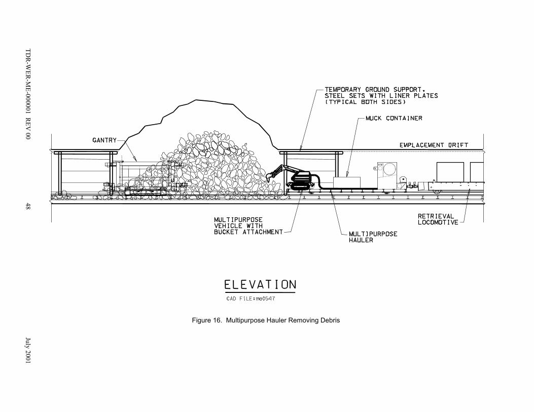
TDR
-WER
-ME-000001 R
EV 00
48July 2001
Figure 16. Multipurpose Hauler Removing Debris
TDR-WER-ME-000001 REV 00 49 July 2001
other stabilization methods. The ground support and related systems would then be rebuilt usingnormal underground construction procedures.
3.3.6.3.3 Retrieval of Contaminated Waste Packages
As soon as contamination above specified limits is detected, or if monitoring indicates unusuallevels of contamination, operational concepts dealing with the mitigation of this abnormal eventwill be instituted. Should the contamination be detected in the WP transporter, it may bedirected to return to decontamination facilities on the surface. If the contamination is detected inan emplacement drift, a remote inspection vehicle could be sent into the drift to verify the leveland source of the contamination. The emplaced WP(s) may need to be retrieved for inspectionand possible decontamination if the contamination level is determined to be above theestablished threshold limits. The following paragraphs will present possible strategies for theretrieval of a potentially contaminated WP.
Two principal strategies may be used to control the movement of contamination during WPtransport and retrieval. These strategies may be used independently or simultaneously aswarranted by the particular situation.
The first strategy is to contain, to the extent possible, the further spread of contamination touncontaminated areas. This is most readily accomplished by the use of physical barriers betweenthe contaminated and uncontaminated areas. HEPA filter bulkheads would be used to containcontamination generated by an abnormal event. Bulkheads could be installed upwind anddownwind from the abnormal event to isolate the contamination site from continued operationsand to maintain worker safety. The second strategy is to prevent the flow of ventilation fromareas of higher contamination to areas of lower contamination. This is most readilyaccomplished by placing an auxiliary ventilation intake near the source of contamination anddirecting the exhaust air through HEPA filters. This can be accomplished by the use of themobile filtration units consisting of HEPA filters, pre-filters, a plenum, and one or more fans.
In the case of a transporter in which high airborne contamination levels have been detected, theappropriate containment strategy would be to seal any openings through which air may leak(e.g., transporter shield doors). This should be accomplished prior to moving the transporterback to the surface. A reduction in the contamination levels may be accomplished by drawingair inside the transporter through a HEPA-filtered exhaust fan. This approach would also havethe additional benefit of creating a negative-pressure air space inside the transporter relative tothe outside air.
During retrieval of one or more suspect WPs from an emplacement drift, all personnel notdirectly involved in the transporter operation will be evacuated from the emplacement side of therepository. The locomotive operators will wear appropriate protective clothing including airfiltration respirators. All of the WPs that are not contaminated will be removed from the driftusing the normal retrieval procedures discussed in Section 3.3.6.2.
The emplacement drift locomotive and multipurpose hauler, carrying the multipurpose vehicle,will then enter the emplacement drift containing the contaminated WP. The multipurpose

TDR-WER-ME-000001 REV 00 50 July 2001
vehicle, under remote control, will cover the accessible surfaces of the WP with a heat-resistant,nonpermeable material, such as lead vinyl or Herculite, to reduce the spread of contaminationduring transport of the WP. After successfully installing the material over the WP/palletassembly the emplacement drift locomotive, multipurpose hauler, and multipurpose vehicle willexit the drift.
After the emplacement drift locomotive, multipurpose hauler, and multipurpose vehicle haveexited the drift, locomotives will transport the gantry carrier and emplacement gantry to thecontaminated emplacement drift entrance. The emplacement gantry will be unloaded in the drift.
A temporary heat-resistant liner or sleeve will be placed inside the WP transporter at the surfacefacilities. Locomotives will then transport the specially fitted WP transporter to thecontaminated emplacement drift entrance. Once the WP transporter is docked at the driftentrance, the emplacement gantry will engage the WP/pallet assembly and carry it to theemplacement drift entrance where it will be lowered onto the bedplate of the WP transporter.The bedplate would retract inside the shielded enclosure of the transporter, the locomotive wouldpull the transporter away from the drift dock, and the WP transporter doors would close. Thesecond locomotive would engage the WP transporter in the main drift and the two locomotiveswould move the WP transporter to a specially prepared decontamination room at the surface.This procedure would have to be repeated for all WPs that are contaminated.
Following the retrieval of contaminated WPs, it will be necessary to perform a radiologicalsurvey on all interior and exterior surfaces of the equipment involved in the operation, (e.g., WPtransporter, emplacement gantry, multipurpose vehicle, multipurpose hauler, and/or gantrycarrier). To reduce the spread of contamination from the WP transporter or gantry surfaces,these surfaces should be decontaminated to the extent possible by using a HEPA-filtered vacuumcleaner or other appropriate method. The equipment shall have an appropriate surface finish andgeometry to facilitate decontamination and limit the accumulation of particulate or surfacecontamination (CRWMS M&O 2000d, Section 1.2.1.21).
In addition, surveys of the main drift, turnout, and all pathways followed by the returningequipment, such as WP transporter, gantry, and gantry carrier, will be performed. Contaminatedareas will be decontaminated in compliance with regulatory requirements and ALARA policies.A contamination survey of the emplacement drift may be needed as well. For an emplacementdrift, a remotely controlled inspection vehicle could perform the survey. If unacceptable levelsof contamination were found, the inspection vehicle would have to be removed from thesubsurface repository using the same procedure as for the emplacement/retrieval gantry. Adecision would then have to be made whether to remove all WPs in that drift and decontaminatethe drift. The waste packages would be removed using the steps discussed above.
3.3.6.4 Evaluation of Lower-Temperature Operating Modes on Retrieval Operations
This section of the report evaluates the five scenarios presented in Sections 3.2.1 through 3.2.5against the operations described in section 3.3.6.
TDR-WER-ME-000001 REV 00 51 July 2001
3.3.6.4.1 Evaluation of Lower-Temperature Operating Modes on Normal RetrievalOperations
The normal retrieval operations will be exactly opposite of the emplacement operationsdescribed in Sections 3.3.3 and 3.3.4. The effects of a lower-temperature repository willtherefore be the same as those identified in Sections 3.3.3.5 and 3.3.4.4. The major impact is thatwith a potentially larger emplacement area, the equipment may require additional maintenancebecause of the longer distances and extended travel times that the equipment must endure ascompared to the base case design.
3.3.6.4.1 Evaluation of Lower-Temperature Operating Modes on Abnormal RetrievalOperations
As stated in Section 3.3.6.3, abnormal retrieval conditions result when one or more abnormalevents occur before or during waste emplacement, caretaking, or normal retrieval operations.Abnormal events may be the result of an unexpected or unplanned process occurring within therepository that would hinder normal operation. In the event that an abnormal condition shouldoccur, cooling of the emplacement drift or location where abnormal retrieval operations arerequired, will be part of the mitigation plan. The Subsurface Ventilation System DescriptionDocument states that the particular location shall be maintained at a maximum temperature of 50°C for remote access to accommodate the retrieval operations (CRWMS M&O 2000c, Section1.2.1.4).
It is anticipated that abnormal retrieval operations will be limited to a localized area of thesubsurface repository. In other words, abnormal retrieval operations would take place in aspecific emplacement drift, emplacement drift turnout, or portion of the main drifts. It is highlydoubtful that the entire repository will require waste package retrieval under abnormalconditions. Because of this reasoning, the effects of a lower-temperature repository will be thesame as the base-case design and the temperature of the operating mode of the repository, shouldit be lower, will have no impact on the intended concepts of abnormal retrieval.
3.4 SYSTEM INTERFACES WITH THE WASTE EMPLACEMENT/RETRIEVALSYSTEM
The Waste Emplacement/Retrieval System must interface with a number of systems to safelyaccomplish the task of emplacing waste. The Waste Emplacement/Retrieval System interfaceswith the Monitored Geologic Repository Operations Monitoring and Control System (MGROMCS) for the transmission of data to and from the emplacement equipment, and for the remotecontrol of the equipment when necessary. The Waste Emplacement/Retrieval System alsointerfaces with the Subsurface Ventilation System for the emplacement drift operatingenvironment and for travel through the emplacement drift isolation doors. The emplacementequipment will travel exclusively on rails and receive electrical power to operate, both functionswill be provided by the Subsurface Emplacement Transportation System. These interfaces arepresented below to discuss the significance of each interface and are shown in Figure 17. For acomplete listing of all other interfaces, refer to the Waste Emplacement/Retrieval SystemDescription Document (CRWMS M&O 2000d, Section 1.2.4).

Figure 17. Waste Emplacement/Retrieval Interface with the MGR Operations Monitoring and Control System
TDR
-WER
-ME-000001 R
EV 00
52July 2001
Emplacement Gantry
Transport Locomotive
Monitored Geologic Repository Operations Monitoring and Control System
Wireless Comm Node Main/Perimeter
Drifts
Data Comm NetworkMain/Perimeter Drifts
WasteEmplacement/
Retrieval System
Wireless Comm NodeEmplacement
Drifts
(RF, Leaky Feeder or Microwave)
(RF, Leaky Feeder or Microwave)
(SS
Fibe
r Opt
ic N
etw
ork)
Rail Switch
Subsurface Transportation System
Subsurface Ventilation System
Drift Isolation Door Multipurpose Vehicle

TDR-WER-ME-000001 REV 00 53 July 2001
3.4.1 Operations Monitoring and Control System (OMCS) Interface
This section will discuss the interface to the MGR OMCS and the relevance of this system in thewaste emplacement process.
The OMCS provides supervisory control, monitoring, and selected remote control of primary andsecondary repository operations. Primary repository operations consist of both surface andsubsurface activities relating to waste receipt, preparation, and emplacement. Secondaryrepository operations consist of support operations for waste handling and waste treatment,utilities, subsurface construction, and Balance-of-Plant activities. Remote control of subsurfaceoperations is the direct responsibility of this system (CRWMS M&O 2000f, Section 6.2.2.1).The system provides repository operational information, alarm capability, and human operatorresponse messages during normal and emergency response situations. The system also has theability to place equipment systems and utilities in a safe operational mode during emergencyresponse situations. The OMCS provides data communications, data processing, managerialreports, data storage, and data analysis.
3.4.1.1 Operator Interfaces and Control Stations
All of the devices for transmission of the emplacement process data will be networked togetherand will allow personnel on the surface to remotely operate the waste emplacement equipment.It is anticipated that the OMCS command center will consist of a control room from which allsubsurface operations will be monitored and controlled. This control room will be equipped withengineering workstations, mainframes, and graphics terminals that will provide the operatorswith direct real-time data. Sufficient storage capacity should exist for time-stamping the data asit is received. This control room will also have a large, wall-sized mimic board so operators canimmediately gain insight as to what is occurring underground. The network can be installed withsufficient access points underground to allow an authorized individual to temporarily hook up alap top or notebook computer and have access to the transmitted data and assume control of theemplacement equipment. Versatility, accuracy, timeliness, and robustness are all attributes thatcan be implemented in the OMCS to enhance the emplacement process.
3.4.1.2 Subsurface Ventilation System Interface
The emplacement equipment will obviously require entry and exit from the emplacement drifts.The only way for this equipment to get into and out of the drifts will be through the emplacementdrift isolation doors that are part of the Subsurface Ventilation System. The OMCS will bemonitoring/controlling the emplacement equipment and will therefore be aware that entry intothe drift is necessary. The sequence of operations and how the interfaces will work is envisionedas follows:
♦ The emplacement equipment enters the drift turnout under the remote control of operatorsthrough the OMCS
♦ The equipment stops just short of the drift isolation doors

TDR-WER-ME-000001 REV 00 54 July 2001
♦ Commands, from the OMCS, will be issued to the Subsurface Ventilation System tostabilize
♦ The Subsurface Ventilation System will notify the OMCS once the ventilation system isready for the drift isolation doors to open
♦ If the conditions are acceptable, the OMCS will direct the Subsurface Ventilation Systemthat it is permissible for the isolation doors to open
♦ The Subsurface Ventilation System will issue commands for the isolation doors to open
♦ The emplacement equipment, still under remote control of operators through the OMCS,will complete the docking process
♦ The emplacement equipment will leave the dock once all operations have been completed
♦ When emplacement equipment is sufficiently clear of the isolation doors, the OMCS willdirect the Subsurface Ventilation System that it is permissible for the isolation doors toclose
♦ The Subsurface Ventilation System will issue commands for the isolation doors to close
♦ The Subsurface Ventilation System will return to normal operation once the doors aredetected to be in the closed position
As shown above, isolation door operation will be an integral component of the wasteemplacement process that will be coordinated by the OMCS. The only direct interface betweenthe Subsurface Ventilation System and the Waste Emplacement/Retrieval System is that thedoors are appropriately sized to permit the equipment to pass through them.
During emplacement operations, the ventilation system will be responsible for controlling thetemperature in the emplacement drifts to a maximum of 50 °C (CRWMS M&O 2000c, Section1.2.1.4). This limit is to ensure operability of all the equipment involved in the operation.
3.4.2 Subsurface Emplacement Transportation (SET) System Interface
All of the emplacement equipment will be rail based. Therefore, wherever the equipment musttravel, rail must be suitably installed. The installation of the rail must include provisions so theemplacement equipment can orient itself in the proper direction prior to traveling underground.The layout of the track on the surface and in the subsurface portion of the repository will bedesigned to have the provision of reversing the direction of the waste emplacement mobileequipment.
Similar to the rail requirements, electrical service must also be provided to the emplacementequipment wherever the equipment must operate. To provide power to equipment in the maindrifts, an overhead trolley wire electrical distribution system will be used (CRWMS M&O 1997,

TDR-WER-ME-000001 REV 00 55 July 2001
Section 8.2). To provide power to equipment in the emplacement drifts, a conductor bar or thirdrail electrical distribution system will be used (CRWMS M&O 1997, Section 8.2). Thedistribution systems will be designed so the required voltage at sufficient ampacity will beprovided to the equipment wherever they are located within the repository.
3.5 AUTOMATION OF THE EMPLACEMENT PROCESS
The current concepts of operation are dependent upon a fair amount of human interaction.Operators are currently slated to drive the locomotives down the main drifts to an area near theturnout of an emplacement drift. The uncoupling operation would then take place, and anoperator would drive the uncoupled locomotive away. The other operator would leave thelocomotive coupled to the transporter and switch control of the locomotive to remote operation.From a remote location, the centralized control room, another operator will control the dockingprocess using joysticks and keyboard commands. This operator depends on video signals andprocess inputs to perform the required steps in the procedure. However, software and hard-wiredinterlocks will still be present within the control system to prevent unsafe operations orcommands from taking place.
An operator from the centralized control room, through the use of joysticks, will control theforward-backward and raise-lower tasks that the gantry is required to perform. Sufficientinformation will be available to the operator so that informed decisions can be made during theemplacement of the WP and movement of the emplacement gantry.
The steps involved in the emplacement process could be totally automated with little to nohuman involvement. It would be possible for an operator to input into a control system the WPidentifier, the emplacement drift number, and the location within the emplacement drift (i.e.,package number 123456789, drift 7, position 4). The control system could be designed torecognize this data and start the batch operation of transferring a WP underground. Once thisinput data has been verified, the rail switches would be automatically set to direct thelocomotives to the appropriate drift entrance. Having received feedback that the rail switcheshave been correctly set, the main control system could give a command to start the locomotives.The locomotives would then travel at the designated speed, while on-board systems monitor allsafety signals. Should an unsafe condition occur, the locomotives would stop and an alarmwould sound at the central command console where a trained operator would evaluate thesituation and commence corrective action.
In the East or West Main Drift, near the appropriate emplacement drift, the locomotives could beprogrammed to begin the docking procedure. This would entail uncoupling the rear locomotiveso the Transporter could appropriately dock at the entrance of the emplacement drift. The gantrywould be suitably positioned within the drift, all doors would open, the transporter would dock,the WP would be released from the Transporter, the gantry would engage the WP and ultimatelyplace it in the designated position within the emplacement drift. This is a simplified version ofthe steps necessary to place the WP in a drift. Nothing in this process rules out the possibility ofautomation.

TDR-WER-ME-000001 REV 00 56 July 2001
If the process were totally automated, additional sensors would be required to adequately informthe control system of the status of all on-going operations. Position, for example, would be aparameter that would require additional proximity sensors or limit switches so the locomotivesand gantry could determine where they are in the repository. Video signals would be providedso that operators would be able to view the operation from the central command station. Inaddition to the additional sensory equipment, the amount of software development for a totallyautomated process would be substantial. The control system would have to incorporate all of thedecision-making algorithms and sequential logic involved in the process of emplacing waste.
From the above information it can be shown that the entire waste emplacement operation can befully automated. However, testing and start-up operations with a completely automated controlsystem may be difficult to accomplish because of the software complexity, purchasingcomponents that can operate reliably in the high temperature and radioactive environment of therepository, maintenance of these components, and the amount of system interfaces required. Therecommended approach is to proceed with the design based upon using primarily humaninteraction. As the physical efforts of moving an 85-metric ton WP become routine, the controlsystem can be further enhanced, in phases, to completely automate the waste emplacementoperation in the future.

TDR-WER-ME-000001 REV 00 57 July 2001
4. CONCLUSIONS
This report has presented a step-by-step concept of operations of how the waste packages couldbe emplaced in the emplacement drifts, and retrieved from drifts using the equipment presentlyincluded in the base case design. These concepts were then evaluated against the effects ofoperating the repository in a lower-temperature operating mode. The lower-temperaturerepository could be achieved by operating the repository in five different modes or operatingscenarios. Brief descriptions of the five scenarios were presented in Section 3.2. It is worthnoting that the Subsurface Ventilation System Description Document (CRWMS M&O 2000c,Section 1.2.1.4) states that underground air temperatures shall be maintained to 50 °C for allareas requiring equipment access for emplacement, retrieval, recovery, and abnormal modes ofoperation. The effects of the five operating scenarios on the intended concept of operations aresummarized below:
Scenario 1–This scenario has the same quantity of waste packages as the base case design. Sincethe waste packages will be spaced 2 meters apart, additional emplacement area will be requiredto accommodate the emplacement of all packages. The effect this will have on the emplacementequipment is that the equipment will be required to travel longer distances to reach the turnoutsof the additional emplacement drifts. The impacts of the longer haulage and travel distances willnot be significant during initial emplacement operations.
Because the equipment will travel longer distances, the cycle time for each trip will increaseslightly. Each round trip will take slightly longer, so the equipment will be operating longer. Itis anticipated that the maintenance schedules of the equipment will most likely be based on run-hours. Therefore, the equipment may require additional maintenance activities for the number oftrips it has made. For example, routine maintenance may be conducted every 40 trips for thebase case design. For this scenario, routine maintenance may need to be conducted every 35 or36 trips. The equipment for waste emplacement will be specified later in the program and exactmaintenance impacts can be determined at that time. It is a logical conclusion, though, thatadditional maintenance will be necessary.
Scenario 2— This scenario has more waste packages than the base case design. Even thoughthe waste packages will be spaced 0.1 meters apart, additional emplacement area will be requiredto accommodate the additional quantity of waste packages. The effect this will have on theemplacement equipment is that the equipment will be required to make additional trips and travellonger distances to reach the turnouts to the emplacement drifts. The impacts of the longerhaulage and travel distances will not be significant during initial emplacement operations.
Similar to scenario 1, the equipment will most likely require additional maintenance activities forthe number of trips it has made. For example, routine maintenance may be conducted every 40trips for the base case design. For this scenario, routine maintenance may need to be conductedevery 35 or 36 trips. This scenario will also have more trips than scenario 1, so the maintenancerequirements will most likely be more than scenario 1.
Scenario 3—This scenario is very similar to scenario 1 except the waste package spacing isthree times larger (6 m) and the emplacement area is 55 percent more. Travel distances per trip

TDR-WER-ME-000001 REV 00 58 July 2001
will increase significantly, as will the equipment maintenance requirements. The maintenanceactivities for this scenario will most likely be more than scenario 1, and equal to or greater thanthose anticipated for scenario 2.
Scenario 4—This scenario is almost identical to scenario 1. It is therefore anticipated that thisscenario will have the same amount of additional maintenance requirements as scenario 1.
Scenario 5—This scenario is almost identical to the base case, and therefore it is anticipated thatthere will be no effect on the intended operational concepts.
Summary—The largest impact will be because of the changes to the physical layout of thesubsurface repository. The first four scenarios have an increased emplacement area because ofincreased waste package spacing or additional waste packages. Because of the increased area,the equipment will need to travel longer distances from the North Portal, which shouldundoubtedly increase the maintenance and/or replacement requirements for the wasteemplacement and retrieval equipment.
Section 3.4 of this report also discussed major system interfaces with the WasteEmplacement/Retrieval System. The base case design currently has leaky feeder and slottedmicrowave communication hardware along with third rail power distribution hardwarepermanently installed in the emplacement drifts (CRWMS M&O 2000a, Section 6.5.3; CRWMSM&O 1997, Section 8.2). While this report focused on the waste emplacement/retrievalequipment it should be noted that reducing the emplacement drift temperature to below 100 °Cshould enhance the operability of this equipment and reduce the uncertainty of this equipmentoperating at higher emplacement drift temperatures. Additional effort in this area isrecommended.

TDR-WER-ME-000001 REV 00 59 July 2001
5. REFERENCES
BSC (Bechtel SAIC Company) 2001a. ANSYS Calculations in Support of Natural VentilationParametric Study for SR. CAL-SVS-HV-000003 REV 00 ICN 01. Las Vegas, Nevada: BechtelSAIC Company. ACC: MOL.20010613.0250.
BSC 2001b. Gantry Structural/Control System Analysis. ANL-WER-MD-000001 REV 00. LasVegas, Nevada: Bechtel SAIC Company. ACC: MOL.20010425.0003.
CRWMS M&O 1997. Repository Rail Electrification Analysis. BCAC00000-01717-0200-00002 REV 00. Las Vegas, Nevada: CRWMS M&O. ACC: MOL.19980122.0462.
CRWMS M&O 1998. Mobile Waste Handling Support Equipment. BCAF00000-01717-0200-00006 REV 00. Las Vegas, Nevada: CRWMS M&O. ACC: MOL.19980819.0397.
CRWMS M&O 2000a. Instrumentation and Controls for Waste Emplacement. ANL-WES-CS-000001 REV 00 ICN 01. Las Vegas, Nevada: CRWMS M&O. ACC: MOL.20000825.0004.
CRWMS M&O 2000b. Retrieval Equipment and Strategy for WP on Pallet. ANL-WES-ME-000006 REV 00. Las Vegas, Nevada: CRWMS M&O. ACC: MOL.20001002.0150.
CRWMS M&O 2000c. Subsurface Ventilation System Description Document. SDD-SVS-SE-000001 REV 01. Las Vegas, Nevada: CRWMS M&O. ACC: MOL.20000803.0356.
CRWMS M&O 2000d. Waste Emplacement/Retrieval System Description Document. SDD-WES-SE-000001 REV 01. Las Vegas, Nevada: CRWMS M&O. ACC: MOL.20000823.0002.
CRWMS M&O 2000e. Waste Package Transport and Transfer Alternatives. ANL-WES-ME-000001 REV 00. Las Vegas, Nevada: CRWMS M&O. ACC: MOL.20000317.0261.
CRWMS M&O 2000f. Subsurface Repository Integrated Control System Design. ANL-MGR-CS-000001 REV 00. Las Vegas, Nevada: CRWMS M&O. ACC: MOL.20000321.0284.
CRWMS M&O 2000g. Operating a Below-Boiling Repository: Demonstration of Concept.TDR-WIS-SE-000001 REV 00. Las Vegas, Nevada: CRWMS M&O. ACC:MOL.20001005.0010.
CRWMS M&O 2001a. Classification of the MGR Waste Emplacement/Retrieval System. ANL-WES-SE-000001 REV 01. Las Vegas, Nevada: CRWMS M&O. ACC: MOL.20010227.0016
CRWMS M&O 2001b. Technical Work Plan for Subsurface Design Section FY 01 WorkActivities. TWP-MGR-MG-000001 REV 01 ADDENDUM D. Las Vegas, Nevada: CRWMSM&O. ACC: MOL.20010417.0455.
DOE (U.S. Department of Energy) 2000. Quality Assurance Requirements and Description.DOE/RW-0333P, Rev. 10. Washington, D.C.: U.S. Department of Energy, Office of CivilianRadioactive Waste Management. ACC: MOL.20000427.0422.

TDR-WER-ME-000001 REV 00 60 July 2001
DOE 2001. Yucca Mountain Science and Engineering Report. DOE/RW-0539. [Washington,D.C.]: U.S. Department of Energy, Office of Civilian Radioactive Waste Management. ACC:MOL.20010524.0272.
NRC (U.S. Nuclear Regulatory Commission) 1998. "Proposed Rule: 10 CFR Part 63---'Disposalof High-Level Radioactive Wastes in a Proposed Geologic Repository at Yucca Mountain,Nevada'." SECY-98-225. [Washington, D.C.: U.S. Nuclear Regulatory Commission]. AccessedOctober 30, 1999. TIC: 240520. http://www.nrc.gov/NRC/COMMISSION/SECYS/1998-225scy.html.
Procedures:
AP-3.11Q, Technical Reports. Rev. 2, ICN 0. Washington D.C.: U.S. Department of Energy,Office of Civilian Radioactive Waste Management. ACC: MOL.20010405.0010.
AP-SV.1Q, Control of the Electronic Management of Information. Rev. 0, ICN 2. WashingtonD.C.: U.S. Department of Energy, Office of Civilian Radioactive Waste Management.ACC: MOL.20000831.0065.
QAP-2-3, Classification of Permanent Items. Rev.10, ICN 0, BSCN 2. Washington D.C.: U.S.Department of Energy, Office of Civilian Radioactive Waste Management.ACC: MOL.20010212.0283.