Civil, Geological and Mining Engineering Keyword: Mines ... · 124 Coulomb 1776; Rankine 1857; Jaky...
34
Draft Numerical investigation of the earth pressure coefficient along the central line of backfilled stopes Journal: Canadian Geotechnical Journal Manuscript ID cgj-2016-0165.R3 Manuscript Type: Note Date Submitted by the Author: 02-Sep-2016 Complete List of Authors: Sobhi, Mohamed Amine; École Polytechnique de Montréal, Department of Civil, Geological and Mining Engineering Li, Li; École Polytechnique de Montréal, Department of Civil, Geological and Mining Engineering Aubertin, Michel; École Polytechnique de Montréal, Keyword: Mines, Backfill, Earth pressure coefficient, Numerical modeling, Rankine https://mc06.manuscriptcentral.com/cgj-pubs Canadian Geotechnical Journal
-
Upload
truongngoc -
Category
Documents
-
view
216 -
download
1
Transcript of Civil, Geological and Mining Engineering Keyword: Mines ... · 124 Coulomb 1776; Rankine 1857; Jaky...

Draft
Numerical investigation of the earth pressure coefficient
along the central line of backfilled stopes
Journal: Canadian Geotechnical Journal
Manuscript ID cgj-2016-0165.R3
Manuscript Type: Note
Date Submitted by the Author: 02-Sep-2016
Complete List of Authors: Sobhi, Mohamed Amine; École Polytechnique de Montréal, Department of Civil, Geological and Mining Engineering Li, Li; École Polytechnique de Montréal, Department of Civil, Geological and Mining Engineering Aubertin, Michel; École Polytechnique de Montréal,
Keyword: Mines, Backfill, Earth pressure coefficient, Numerical modeling, Rankine
https://mc06.manuscriptcentral.com/cgj-pubs
Canadian Geotechnical Journal

Draft
1
2
(cgj-2016-0165R3) 3
4
Numerical investigation of the earth pressure coefficient 5
along the central line of backfilled stopes 6
7
8
Mohamed Amine Sobhi, Li Li*, and Michel Aubertin 9
10
11
12
Research Institute on Mines and the Environment 13
Department of Civil, Geological and Mining Engineering 14
École Polytechnique de Montréal 15
C.P. 6079, Succursale Centre-Ville, Montréal, PQ, H3C 3A7 Canada 16
17
18
*Corresponding author. Tel: 1-514-340-4711 #2408; fax: 1-514-340-4477; 19
e-mail: [email protected] 20
21
22
Technical note (cgj-2016-0165R3) resubmitted to Canadian Geotechnical Journal 23
24
25
26
Submitted: March 2015 27
Evaluation received: May 2015 28
Revised version submitted: March 2016 29
Second evaluation received: May 2016 30
Updated (Revised) version submitted: June 2016 31
Third evaluation received: July 2016 32
Re-updated version submitted: August 2016 33
Forth evaluation received: August 2016 34
Fifth version submitted: September 2016 35
36
Page 1 of 33
https://mc06.manuscriptcentral.com/cgj-pubs
Canadian Geotechnical Journal

Draft
2
Numerical investigation of the earth pressure coefficient 37
along the central line of backfilled stopes 38
39
Mohamed Amine Sobhi, Li Li∗, and Michel Aubertin 40
41
Abstract: The earth pressure coefficient K, defined as the horizontal to vertical normal 42
(effective) stresses ratio (σh/σv), is a key parameter in analytical solutions for estimating the 43
stresses in backfilled stopes. In the case of vertical stopes, the value of K has sometimes been 44
defined using the at-rest earth pressure coefficient K0, while others have applied Rankine’s 45
active earth pressure coefficient Ka. To help clarify this confusing situation, which can lead to 46
significantly different results, the origin and nature of the at-rest and Rankine’s active 47
coefficients are first briefly recalled. The stress state in backfilled stopes is then investigated 48
using numerical simulations. The results indicate that the value of K can be close to Ka for 49
cohesionless backfills along the vertical central line (CL) of vertical stopes, due to sequential 50
placement and partial yielding of the backfill. For inclined stopes, simulations show that the 51
ratio between the minor and major principal stresses (σ3/σ1) along the CL in the backfill, 52
which differs from σh/σv, can also be close to Ka. A simple expression is shown to represent 53
well the horizontal to vertical stresses ratio σh/σv (= K) along the central line of such inclined 54
stopes. A discussion follows on the effects of backfill properties and simulation approach. 55
56
Key-words: Mines, Backfill, Earth pressure coefficient, Numerical modeling, Rankine. 57
58
∗Corresponding author. Tel: 1-514-340-4711 #2408; fax: 1-514-340-4477; e-mail: [email protected]
Page 2 of 33
https://mc06.manuscriptcentral.com/cgj-pubs
Canadian Geotechnical Journal

Draft
3
Résumé: Le coefficient de poussée des terres K, défini comme le rapport entre les contraintes 59
normales (effectives) horizontale et verticale (σh/σv), est un paramètre clé utilisé dans les 60
solutions analytiques pour estimer les contraintes dans des chantiers remblayés. Pour les 61
chantiers verticaux, la valeur de K est occasionnellement définie selon le coefficient de 62
poussée des terres au repos K0, alors que d'autres ont plutôt utilisé le coefficient de poussée 63
des terres actif de Rankine Ka. Pour clarifier cette situation ambigüe, qui peut conduire à des 64
résultats assez différents, l’origine et la nature des coefficients au repos et actif sont d’abord 65
brièvement rappelés. L’état des contraintes dans des chantiers remblayés est évalué à partir de 66
simulations numériques. Les résultats indiquent que cette valeur peut être proche du 67
coefficient Ka pour les remblais sans cohésion le long de la ligne de centre dans les chantiers 68
verticaux, en raison de la mise en place progressive et de l’atteinte d’un état de plasticité 69
partiel du remblai. Pour les chantiers remblayés inclinés, les résultats montrent que le rapport 70
entre les contraintes principales mineure et majeure (σ3/σ1) le long de la ligne de centre dans 71
le remblai, qui diffère du rapport σh/σv, peut aussi être proche du coefficient de poussée des 72
terres actif de Rankine. Une expression simple peut être utilisée pour représenter le rapport 73
entre les contraintes horizontale et verticale σh/σv (= K) le long de la ligne centrale des 74
chantiers remblayés inclinés. Une discussion suit en lien avec l’effet des propriétés du remblai 75
et de l’approche pour mener les simulations. 76
77
Mots-clés: Mines, Remblai, Coefficient de poussée des terres, Modélisation numérique, 78
Rankine.79
Page 3 of 33
https://mc06.manuscriptcentral.com/cgj-pubs
Canadian Geotechnical Journal

Draft
4
Introduction 80
Stope backfilling is widely used in Canada and elsewhere, in part because it helps reduce the 81
environmental impact of mining operations by returning mining wastes underground 82
(Bussière 2007; Benzaazoua et al. 2008). But the main purposes of mine backfill are to 83
improve ground stability, provide a safer work space, reduce ore dilution, and help control the 84
air flow (Hassani and Archibald 1998; Darling 2011; Hambley 2011). 85
A key issue for the design of backfilled stopes is the determination of the stresses in the 86
backfill. A few analytical expressions have been proposed to this effect. These are mostly 87
based on the approach adopted by Marston (1930), who made use of the Janssen (1895) 88
arching theory to calculate the vertical load on buried conduits in backfilled trenches. The 89
corresponding vertical stress can be expressed as follows: 90
(1)
−−= hB
K
K
B δδ
γσ
tan2exp1
tan2v 91
where B (m) is the width of the opening, h (m) is the depth in the fill, γ (kN/m3) is its unit 92
weight, δ (°) is the friction angle along the interfaces between the backfill and wall material, 93
and K (-) is the earth pressure coefficient which is defined as the ratio between the horizontal 94
(σh) and vertical (σv) normal effective stresses (kPa). For narrow openings, eq. (1) typically 95
leads to vertical stresses that are much smaller than the overburden stresses, due to a load 96
transfer from the soft backfill to the stiff walls, thus producing an arching effect (e.g., Handy 97
and Spangler 2007). 98
Equation (1) has been applied to vertical mine backfilled stopes using δ = ϕ, where ϕ (°) is 99
the internal friction angle of the (cohesionless) backfill (Aubertin et al. 2003). This 100
assumption implies that the strength along the fill-wall interfaces is controlled by the backfill 101
strength, hence considering that yielding occurs in the fill material rather than directly along 102
the walls (due to their very rough surface). 103
Page 4 of 33
https://mc06.manuscriptcentral.com/cgj-pubs
Canadian Geotechnical Journal

Draft
5
This type of formulation has also been extended for inclined backfilled stopes (e.g., 104
Caceres 2005; Ting et al. 2011, 2014; Jahanbakhshzadeh 2016). 105
The effects of cohesion and of a three-dimensional geometry (Li et al. 2005), pore water 106
pressures (Li and Aubertin 2009a, 2009b), and non-uniform stress distribution across the 107
stope width (Li and Aubertin 2008, 2010) have also been introduced in modified expressions 108
based on eq. (1). Other 3D formulations, also related to eq. (1), have been proposed by Van 109
Horn (1964), Winch (1999), and Pirapakaran and Sivakugan (2007a). 110
All these solutions (and others) use the lateral earth pressure coefficient, K, as a state 111
parameter to evaluate the stresses in backfilled openings. The value of K can significantly 112
affect the calculated stresses within the backfill (Li et al. 2003). There is however an 113
uncertainty regarding how K should be defined for backfilled stopes. This issue is addressed 114
in the following, considering first the basic concept behind K and then analyzing the stresses 115
along the central line of stopes using results from numerical simulations. Although the 116
calculations presented here neglect the effect of pore water pressure, the same concept can 117
easily be extended to cases where the backfill contains water that generates positive pressures 118
(e.g., Li and Aubertin 2009a, 2009b). 119
120
Earth pressure coefficient K 121
The well-known earth pressure coefficient concept was originally developed in soil mechanics 122
to analyse the stress state in natural deposits and the pressure on retaining walls (e.g., 123
Coulomb 1776; Rankine 1857; Jaky 1944; Lambe and Whitman 1979; Terzaghi et al. 1996). 124
The corresponding earth pressure coefficient K is usually defined as the ratio between the 125
horizontal (σh) and vertical (σv) normal stresses, which are also the minor (σ3) and major (σ1) 126
principal stresses in a normally consolidated soil deposit with a horizontal surface (i.e. σh/σv = 127
σ3/σ1). 128
Page 5 of 33
https://mc06.manuscriptcentral.com/cgj-pubs
Canadian Geotechnical Journal

Draft
6
When a soil in a semi-infinite space is under static equilibrium, the vertical (principal) 129
stress, σv, can be expressed as follows: 130
(2) hγσ =v 131
The horizontal stress is proportional to the vertical stress, so one can write: 132
(3) σh = K σv 133
Equations (2) and (3) constitute the traditional overburden solution for estimating the stresses 134
in a soil deposit in geotechnical engineering. Parameter K is usually called the (lateral) earth 135
pressure coefficient, or a close variant of this term (e.g., Bowles 1992; CGS 2006; McCarthy 136
2007; Holtz et al. 2011). 137
For a normally consolidated soil at-rest (i.e. where vertical loads do not induce horizontal 138
strain), K = K0. Although the value of K0 can theoretically be defined from Poisson’s ratio µ 139
(e.g., Aysen 2005; Blight 2010), geotechnical engineers generally use the following semi-140
empirical expression proposed by Jaky (1944), which relates the at-rest earth pressure 141
coefficient to the (effective) internal friction angle (ϕ) of the soil: 142
(4) φsin10 −=K 143
A number of researchers have shown that Jaky’s expression (eq. (4)) represents well the 144
measured horizontal to vertical stresses ratio for normally consolidated soils (e.g., Al-145
Hussaini and Townsend 1975; Ladd et al. 1977; Mesri and Hayat 1993). 146
When a soil (or fill) submitted to vertical loading is retained by a smooth vertical wall of 147
limited stiffness, there will be some horizontal movement that may result in a reduction in the 148
horizontal stress σh (compared with the K0 condition). The Mohr circle defining the new stress 149
state can then meet the Coulomb yield surface (e.g., McCarthy 2007; Sobhi et al. 2014). In 150
this case, the soil is said to have reached an active state following yielding. The corresponding 151
horizontal to vertical stresses ratio can then be defined with Rankine’s active earth pressure 152
Page 6 of 33
https://mc06.manuscriptcentral.com/cgj-pubs
Canadian Geotechnical Journal

Draft
7
coefficient, Ka, which can be expressed as follows for a horizontal surface (e.g., CGS 2006; 153
Das 2010): 154
(5)
−°=+−
===2
45tansin1
sin1 2
1
3
v
ha
φφφ
σσ
σσ
K 155
Equations (4) and (5) have both been used to calculate the stresses in backfilled openings, 156
including mine stopes. It is however unclear which one (if any) of these two expressions 157
should be applied in such cases. 158
159
Assessing the value of K for mine backfilled stopes 160
As stated above, analytical solutions developed for estimating the stresses in backfill placed in 161
mine stopes are usually based on Marston’s approach (eq. (1)). For vertical backfilled stopes, 162
some numerical calculations and indirect measurements have indicated that Rankine’s active 163
earth pressure coefficient (eq. (5)) is close to the horizontal to vertical stresses ratio along the 164
central line (e.g., Li et al. 2003, 2005; Li and Aubertin 2009a, 2009b; Ting et al. 2012). Using 165
the value of coefficient Ka also agrees with Marston’s (1930) results for the loads on conduits 166
in backfilled trenches (see also McCarthy 1988; Handy and Spangler 2007). 167
An illustration of how the value of K may influence the stress state in a backfilled opening 168
is shown in Fig. 1, using experimental results taken from Pirapakaran and Sivakugan (2007b) 169
and the 3D arching solution of Li et al. (2005), which is a direct extension of eq. (1). Both the 170
at-rest K0 (eq. (1)) and Rankine’s active Ka (eq. (5)) coefficients have been used to calculate 171
the vertical stresses shown in the figure. As can be seen, the experimental results indicate that 172
there is a pronounced arching effect, with the measured vertical stresses being much smaller 173
than the overburden pressures (especially at depth). It can also be observed that a better 174
agreement between the experimental measurements and analytical solution is obtained in this 175
case with Rankine’s active earth pressure coefficient. This agrees with earlier analyses of 176
Page 7 of 33
https://mc06.manuscriptcentral.com/cgj-pubs
Canadian Geotechnical Journal

Draft
8
experimental and analytical results presented by Li et al. (2005), which showed that a good 177
agreement can be obtained for K = Ka. 178
Nonetheless, many authors working on the behavior of fills in bins and in trenches or 179
behind retaining walls have been using K = K0 in analytical solutions to define the stresses 180
(e.g., Take and Valsangkar 2001; Blight 2006). This assumption was also adopted for 181
backfilled stopes (e.g., Winch 1999; Pirapakaran and Sivakugan 2007a, 2007b; Fahey et al. 182
2009; Singh et al. 2010, 2011; Ting et al. 2011). In such cases, the use of K = K0 may appear 183
to be justified because the walls are very stiff, so the horizontal displacements (and strains) in 184
the backfill should be very small (or nil), hence leading to an at-rest state. This assumption 185
could however be questioned because the high compressibility of the fill, its sequential 186
placement, and the presence of the rock walls can lead to some stress rotation and differential 187
lateral strains under vertical loading, as indicated for instance by numerical simulations 188
performed by Falaknaz (2014; see also Falaknaz et al. 2015b). In the following, additional 189
analyses are performed using numerical simulations to assess the earth pressure coefficient 190
along the central line (CL) of backfilled stopes with parallel vertical and inclined walls. 191
192
Numerical simulations 193
Numerical simulations have been performed to assess the stress ratio in backfilled stopes, 194
considering the effect of stope geometry and backfill properties. The focus is placed here on 195
the earth pressure coefficient K (= σh/σv) along the central line of the stopes, where the effects 196
of the shear stresses developing along the walls are minimal. The finite element software 197
SIGMA/W (GEO-SLOPE 2010) was used to run the simulations; additional details are 198
provided in Sobhi (2014). 199
Figure 2a shows a backfilled stope model, which includes a void space of 0.5 m above the 200
fill surface. The backfill is considered homogeneous and isotropic and it obeys the classical 201
Page 8 of 33
https://mc06.manuscriptcentral.com/cgj-pubs
Canadian Geotechnical Journal

Draft
9
elasto-plastic model with the Coulomb yield criterion; the rock mass is isotropic, homogenous 202
and linear elastic. A typical stress regime for the Canadian Shield is applied, where the natural 203
vertical in-situ stress is calculated based on the overburden weight and the horizontal natural 204
stress is twice the vertical stress. An example of a numerical model built in SIGMA/W is 205
shown in Fig. 2b. 206
Each numerical simulation was conducted in three steps: i) model construction to obtain a 207
rock mass space submitted to the external and self-weight stress regime; ii) excavation of the 208
stope and release of elastic strains in the rock mass; iii) backfilling of the stope in four layers 209
(similarly to Li and Aubertin 2009c). There is no interface element along the rock walls in the 210
models; this may influence the magnitude of the stresses obtained with SIGMA/W (El 211
Mkadmi et al. 2014), but it does not significantly affect the stress ratio being assessed here 212
(Sobhi 2014). 213
The reference case configuration consists of a 6 m wide and 45 m high vertical stope 214
surrounded by the elastic rock mass characterized by Er = 30 GPa (Young’s modulus), µr = 215
0.3 (Poisson’s ratio) and γr = 27 kN/m3 (unit weight). The stope is filled with a cohesionless 216
backfill characterized by E = 300 MPa, µ = 0.2, γ = 18 kN/m3, ϕ = 30° (friction angle) and ψ = 217
0° (dilation angle, with a non-associated flow rule). 218
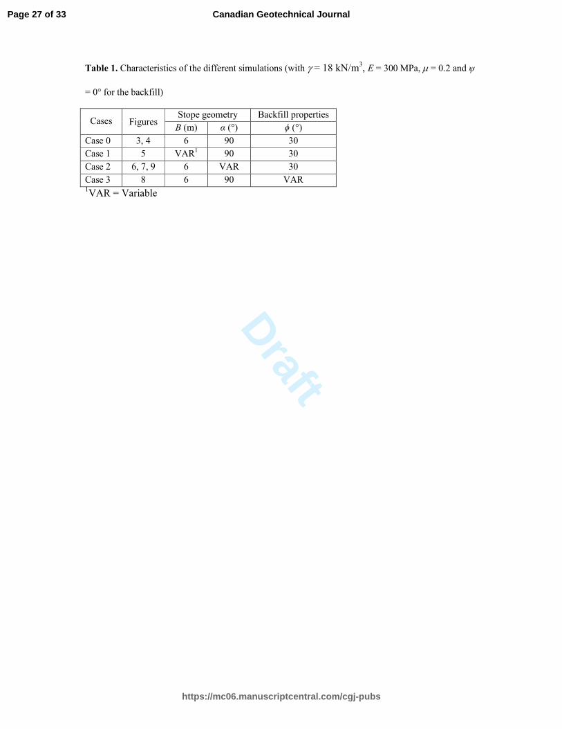
In addition to the reference case, various other simulations have been conducted with one 219
parameter varied at a time in order to evaluate its influence on the earth pressure coefficient 220
K. Details on the reference case and other simulated cases are summarized in Table 1. 221
222
Numerical results 223
Reference case 224
Figure 3 shows the vertical and horizontal stresses distribution (Fig. 3a) along the CL of the 225
vertical stope for the reference case, together with the iso-contours of the horizontal σh (Fig. 226
Page 9 of 33
https://mc06.manuscriptcentral.com/cgj-pubs
Canadian Geotechnical Journal

Draft
10
3b) and vertical σv (Fig. 3c) stresses obtained with SIGMA/W. From Figure 3a, it can be seen 227
that there is a nonlinear stress increase with depth. Across the width of the stope, the 228
horizontal (Fig. 3b) and vertical (Fig. 3c) stresses tend to decrease from the stope center to the 229
walls. These correspond well to typical stress distribution in backfilled openings due to 230
arching effect (Li et al. 2003; Li and Aubertin 2008, 2009c; Falaknaz 2014; Falaknaz et al. 231
2015a). 232
The earth pressure coefficient K is calculated as the ratio between the horizontal and 233
vertical stresses along the central line obtained with the code SIGMA/W. The numerical 234
results giving the variation of coefficient K with depth along the CL of the vertical backfilled 235
stope for the reference case configuration is shown in Fig. 4. The Rankine's active coefficient 236
Ka = 0.33 (Eq. (5) with ϕ = 30°) and the at-rest coefficient based on Jaky’s equation K0 = 0.5 237
(Eq. (4) with ϕ = 30°) are also shown on Fig. 4. It is seen that the value of K obtained from the 238
numeral simulation is close to Ka along most of the CL. However, the value of K tends toward 239
Jaky’s (eq. (4)) at-rest coefficient K0 in the upper part of the stope. 240
These numerical results correspond well to the tendency reported by Thompson et al. 241
(2012), based on measurements performed at the Cayeli mine, located in the province of Rize, 242
Turkey; these indicated that the effective stresses in the backfill in the lower central portion of 243
a stope were close to an active state while the upper portion was near to the at-rest state. 244
245
Effect of stope geometry 246
Figure 5 shows the variation of K (= σh/σv) along the CL of vertical stopes width B ranging 247
from 4 m to 10 m (Case 1, Table 1). One sees that the earth pressure coefficient remains very 248
close to Rankine’s active earth pressure coefficient Ka (eq. (5)) for all simulations. As was the 249
case for Case 0 (Fig. 4), the simulated value of K appears somewhat overestimated by Jaky’s 250
equation (eq. (4)), except near the top. 251
Page 10 of 33
https://mc06.manuscriptcentral.com/cgj-pubs
Canadian Geotechnical Journal

Draft
11
The variation of the earth pressure coefficient K = σh/σv along the CL of backfilled stopes 252
with walls having various inclination angles α (between 90° to 50°) is shown in Fig. 6. It is 253
seen that the value of coefficient K is very sensitive to angle α. There is a significant increase 254
in the value of K with a decrease of the wall inclination angle. This tendency agrees with the 255
numerical simulations results of Li and Aubertin (2009c), who showed that the horizontal 256
stresses are almost insensitive to the stope inclination while the vertical stresses tend to 257
decrease when α decreases. The observed trend also agrees with those reported by Li et al. 258
(2012, 2013) and Li and Aubertin (2015) for trenches with inclined walls. 259
This increase in the value of K with a decrease of angle α was thus expected, but the 260
magnitude of this effect was not necessarily anticipated. 261
For the stope geometry and backfill properties considered here, the earth pressure 262
coefficient K for vertical (α = 90°) and sub-vertical (α = 80°) stopes along the CL is well 263
represented by the Rankine’s active earth pressure. Jaky’s at-rest earth pressure coefficient 264
(eq. (4)) is less representative of the simulations results, except may be for α = 60° (but this 265
agreement may be fortuitous) 266
The results shown in Fig. 6 furthermore indicate that the expressions presented above 267
cannot directly be used to represent the earth pressure coefficient K (= σh/σv, along the CL) 268
when the wall inclination angle varies significantly from 90°; the difference with the value of 269
Ka becomes particularly important for α ≤ 70° (for the conditions analyzed here). This aspect 270
will be further discussed below. 271
Additional analysis of the numerical simulations results indicates that for stopes with 272
inclined walls, the horizontal and vertical stresses along the CL are not principal stresses, 273
contrarily to vertical stopes (where σh/σv = σ3/σ1). 274
The ratio of the principal (effective) stresses Kps = σ3/σ1 along the CL was evaluated for 275
various stope inclination angles α. As it can be seen on Fig. 7, the value of Kps is close to 276
Page 11 of 33
https://mc06.manuscriptcentral.com/cgj-pubs
Canadian Geotechnical Journal

Draft
12
Rankine's active coefficient Ka, except very near the top of the backfill. This suggests that the 277
backfill may be fairly close to an active state along the CL of inclined stopes (when the latter 278
state is defined from the principal stresses). 279
280
Effect of backfill properties 281
Various characteristics of the backfill have been varied in the following simulations to assess 282
their influence on the stress state and on the value of K. It is first noted that the numerical 283
calculations have shown that there is no influence of the backfill Young’s modulus on the 284
lateral earth pressure coefficient for E between 3 MPa to 3 GPa (results not shown here). 285
There is however a significant effect of Poisson’s ratio µ on the stress state (Li and Aubertin 286
2009c; Falaknaz et al. 2015b; Jahanbakhshzadeh 2016); this aspect will be discussed briefly 287
below. 288
As the internal friction angle ϕ of the backfill (for a constant µ value) influences the stress 289
state in stopes (Li and Aubertin 2009c), it was also expected to affect the value of coefficient 290
K. Figure 8 shows that the value of K given by the simulations is usually fairly close to 291
Rankine’s active earth pressure coefficient (eq. (5)) for values of ϕ going from 10° to 40°, 292
particularly in the deeper part of the stope. 293
294
An expression for coefficient K in inclined stopes 295
In the case of narrow inclined stopes, the simulations showed that the horizontal and vertical 296
stresses along the CL are not principal stresses (because of the induced shear stresses). The 297
results shown above have also shown that the ratio of the principal stresses Kps (= σ3/σ1) is 298
close to Ka. 299
Page 12 of 33
https://mc06.manuscriptcentral.com/cgj-pubs
Canadian Geotechnical Journal

Draft
13
The numerical results further indicated that the earth pressure coefficient K (= σh/σv) is 300
very sensitive to the stope walls inclination angle α. This aspect is not taken into account in 301
the equations presented above. 302
An analysis of the simulations results has shown that the following expression represents 303
well the value of the earth pressure coefficient as a function of the stope inclination α and the 304
backfill internal friction angle ϕ: 305
αα 2cos2
1
2
1 aa KKKK
−+
+== (6) 306
where α (50° ≤ α ≤ 90°) is the stope wall inclination angle and Ka is Rankine’s active earth 307
pressure coefficient. Equation (6) defining Kα (= σh/σv) is based on an expression presented by 308
Ting et al. (2011), but which does not consider Rankine’s active state (and which also 309
includes an additional term that is a function of the friction angle along the walls; this term is 310
not considered here). 311
Figure 9 shows a comparison between the value of Kα calculated with eq. (6) and the earth 312
pressure coefficient K (= σh/σv) obtained from the numerical simulations for different stope 313
inclination angles, for a backfill internal friction angle of 30°. It is seen that a good agreement 314
is obtained for α varying from 50° to 90°. 315
Additional numerical simulations were performed using an internal friction angle ϕ = 20° 316
and 40° for the backfill (see Sobhi 2014). Again, a good agreement is obtained between the 317
earth pressure coefficient Kα calculated with eq. (6) and those obtained from the numerical 318
simulations along the central line. 319
These results thus suggest that eq. (6) can be used to determine the earth pressure 320
coefficient K along the CL of inclined stopes backfilled with cohesionless material. 321
322
Discussion 323
Page 13 of 33
https://mc06.manuscriptcentral.com/cgj-pubs
Canadian Geotechnical Journal

Draft
14
The numerical modeling results presented above indicate that the active earth pressure 324
coefficient Ka could be applied to assess the stresses along the CL of vertical backfilled stopes 325
with solutions based on Marston’s equation (eq. (1)), except very near the top surface where 326
the backfill is closer to an at-rest state. This suggests that K should also be expressed as a 327
function of the depth h, as shown by the recent work of Jahanbakhshzadeh (2016). 328
The results specifically show that there is an increase in the value of K near the top of the 329
backfill. This could be related to the effect of backfill placement (added in layers), which 330
tends to produce vertical and horizontal stresses that can be initially much higher than the 331
overburden. Near the surface, the excess stresses in the backfill can be released in the vertical 332
direction, but these are partly locked in the horizontal direction, hence producing a higher 333
horizontal to vertical stress ratio (i.e. larger value of K). 334
As mentioned previously, the trends provided by the numerical results have also been 335
confirmed (in part) by those provided by field measurements at the Cayeli mine, located in the 336
province of Rize, Turkey (Thompson et al. 2012). Similar experimental observations, which 337
point in the same direction, have also been reported for the Goldcorp Inc.’s Red Lake Mine 338
(Hughes et al. 2010) and for laboratory tests on physical models (Fig. 1; see also Pirapakaran 339
and Sivakugan 2007b; Ting et al. 2012). 340
More laboratory work on this aspect can be needed. But, these numerical and experimental 341
results may appear to be going against intuition for backfilled stopes, as it could be expected 342
that the very stiff rock walls would produce an at-rest state (K = K0) in the openings (as is 343
postulated by some). 344
This apparent conundrum may be resolved, at least partially, by recalling that Rankine’s 345
active state is related to yielding of the material (e.g., McCarthy 2007; Sobhi et al. 2014). A 346
movement of the confining walls is not a necessary condition to reach an active state in a 347
backfilled stope. Such active (yielding) state can also be reached as a result of other 348
Page 14 of 33
https://mc06.manuscriptcentral.com/cgj-pubs
Canadian Geotechnical Journal
Draft
15
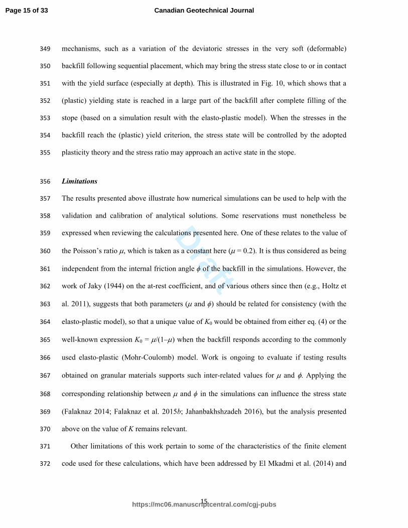
mechanisms, such as a variation of the deviatoric stresses in the very soft (deformable) 349
backfill following sequential placement, which may bring the stress state close to or in contact 350
with the yield surface (especially at depth). This is illustrated in Fig. 10, which shows that a 351
(plastic) yielding state is reached in a large part of the backfill after complete filling of the 352
stope (based on a simulation result with the elasto-plastic model). When the stresses in the 353
backfill reach the (plastic) yield criterion, the stress state will be controlled by the adopted 354
plasticity theory and the stress ratio may approach an active state in the stope. 355
Limitations 356
The results presented above illustrate how numerical simulations can be used to help with the 357
validation and calibration of analytical solutions. Some reservations must nonetheless be 358
expressed when reviewing the calculations presented here. One of these relates to the value of 359
the Poisson’s ratio µ, which is taken as a constant here (µ = 0.2). It is thus considered as being 360
independent from the internal friction angle ϕ of the backfill in the simulations. However, the 361
work of Jaky (1944) on the at-rest coefficient, and of various others since then (e.g., Holtz et 362
al. 2011), suggests that both parameters (µ and ϕ) should be related for consistency (with the 363
elasto-plastic model), so that a unique value of K0 would be obtained from either eq. (4) or the 364
well-known expression K0 = µ/(1‒µ) when the backfill responds according to the commonly 365
used elasto-plastic (Mohr-Coulomb) model. Work is ongoing to evaluate if testing results 366
obtained on granular materials supports such inter-related values for µ and φ. Applying the 367
corresponding relationship between µ and ϕ in the simulations can influence the stress state 368
(Falaknaz 2014; Falaknaz et al. 2015b; Jahanbakhshzadeh 2016), but the analysis presented 369
above on the value of K remains relevant. 370
Other limitations of this work pertain to some of the characteristics of the finite element 371
code used for these calculations, which have been addressed by El Mkadmi et al. (2014) and 372
Page 15 of 33
https://mc06.manuscriptcentral.com/cgj-pubs
Canadian Geotechnical Journal

Draft
16
Sobhi (2014). For instance, the analyses conducted by Sobhi (2014) indicate that the 373
magnitude of the stresses in the stope may depend on the number of layers used to place the 374
backfill in the modelled opening and on the conditions imposed along the rock walls (i.e. 375
presence or absence of interface or transition elements). However, these factors do not 376
influence the value of the stress ratio σh/σv obtained from the numerical simulations. The 377
results presented here are thus representative of the conditions being evaluated to assess the 378
value of K. 379
Also, it should be recalled that the focus of this study was placed on the earth pressure 380
coefficient along the CL of backfilled stopes, where the principal stresses would typically act 381
along the vertical and horizontal axes (in plane strain). It is known however that the stresses 382
and earth pressure coefficients are not uniform across the width of the openings (Li and 383
Aubertin 2008, 2010). Additional work is underway to assess the value of K across the width 384
and near the walls of backfilled stopes. 385
Interface elements were not included in the models used here. Recent simulations 386
performed by Liu et al. (2016a, 2016b) tend to indicate that the introduction of interface 387
elements is usually not required when the surface of the walls are very rough (irregular), or 388
when the friction angle along the walls is close to that of the backfill; the latter condition has 389
been observed from recent laboratory tests results (e.g., Fall and Nasir 2010; Koupouli et al. 390
2016). Nonetheless, this aspect still needs some more work. 391
Finally, it should be recalled that eq. (6) was formulated for inclined stopes, while eq. (1) 392
was developed for vertical stopes. Their combined use may thus be questioned, as these are 393
based on different assumptions and conditions. Nonetheless, as is often the case with other 394
types of empirical formulations used in geotechnical engineering (such as Jaky’s equation for 395
K0), it is deemed reasonable to introduce the value of K given by eq. (6) into eq. (1) to obtain 396
a preliminary estimate of the stresses along the CL of inclined stopes. 397
Page 16 of 33
https://mc06.manuscriptcentral.com/cgj-pubs
Canadian Geotechnical Journal

Draft
17
398
Conclusion 399
This study presents the results of a numerical investigation conducted with a finite element 400
code to evaluate the effect of stope geometry and backfill properties on the lateral earth 401
pressure coefficient K (= σh/σv) within backfilled stopes. The simulations results indicate that 402
the value of coefficient K along the CL of vertical backfilled stopes can be close to Rankine's 403
active coefficient Ka, except near the fill surface. This suggests that the backfill along the CL 404
may be approaching an active state in vertical stopes. As the rock walls do not move 405
significantly, the simulations results also suggest that the backfill state cannot be solely 406
associated with the displacement of these walls. A yielding state, leading to Rankine’s active 407
condition, appears to be induced in some parts of the stope due to the natural response of the 408
very soft backfill, which can generate increased (and non-uniform) deviatoric stresses that 409
tends to mobilize the yield strength following filling and settlements. This tendency applies to 410
vertical and inclined stopes. In the latter case however, it has been observed that it is the ratio 411
of the principal stresses Kps = σ3/σ1 (in 2D) that seems to be approaching Rankine's active 412
coefficient Ka along the inclined CL of the stope. In addition, an empirical equation is 413
proposed for estimating the earth pressure coefficient K = Kα = σh/σv along the CL of inclined 414
stopes backfilled with a cohesionless backfill. 415
416
Acknowledgment 417
The authors acknowledge the financial support of the Natural Sciences and Engineering 418
Research Council of Canada (NSERC 402318), the Institut de recherche Robert-Sauvé en 419
santé et en sécurité du travail (IRSST 2013-0029), Fonds de recherche du Québec ― Nature 420
et technologies (FRQNT 2014-MI-183747, 2015-MI-191676), and the industrial partners of 421
the Research Institute on Mines and the Environment (RIME UQAT-Polytechnique; 422
Page 17 of 33
https://mc06.manuscriptcentral.com/cgj-pubs
Canadian Geotechnical Journal

Draft
18
http://rime-irme.ca). Particular thanks are also expressed to the Editor, Associate Editor and 423
anonymous reviewers for their constructive comments. 424
425
References 426
Al-Hussaini, M., and Townsend, F. 1975. Stress deformation of sand under K0 conditions. In 427
Proceedings 5th Panamerican Conference on Soil Mechanics and Foundation Engineering. Vol. 1, 428
pp. 129-136. 429
Aubertin, M., Li L., Arnoldi, S., Belem, T., Bussière, B., Benzaazoua, M., and Simon, R. 2003. 430
Interaction between backfill and rock mass in narrow stopes. In Proceedings, Soil and rock 431
America 2003. Edited by P. J. Culligan, H. H. Einstein, and A. J. Whittle. Verlag Glückauf Essen 432
(VGE), Essen, Germany. Vol. 1, pp. 1157–1164. 433
Aysen, A. 2005. Soil mechanics: Basic concepts and engineering applications, Taylor & Francis, New 434
York. 435
Benzaazoua, M., Bussière, B., Demers, I., Aubertin, M., Fried, É., and Blier, A. 2008. Integrated mine 436
tailings management by combining environmental desulphurization and cemented paste backfill: 437
Application to mine Doyon, Quebec, Canada. Minerals Eng., 21: 330–340. 438
Blight, G. 2006. Assessing loads on silos and other bulk storage structures: Research applied to 439
practice. Taylor & Francis, Rotterdam, Netherlands. 440
Blight, G. 2010. Geotechnical engineering for mine waste storage facilities. CRC Press, Netherlands. 441
Bowles, J.E. 1992. Engineering properties of soils and their measurement, 4th Edition. McGraw-Hill. 442
Bussière, B. 2007. Colloquium 2004: Hydro-geotechnical properties of hard rock tailings from metal 443
mines and emerging geo-environmental disposal approaches. Canadian Geotechnical Journal, 444
44(9): 1019–1052. 445
Caceres, C. 2005. Effect of delayed backfill on open stope mining methods. M.S. thesis, University of 446
British Columbia, Vancouver, B.C. 447
CGS 2006. Canadian foundation engineering manual, 4th Edition. Canadian Geotechnical Society. 448
Page 18 of 33
https://mc06.manuscriptcentral.com/cgj-pubs
Canadian Geotechnical Journal

Draft
19
Coulomb, C.A. 1776. Essai sur une application des règles de maximis & minimis à quelques 449
problèmes de statique, relatifs à l'architecture. Mémoires de mathématique & de physique présentés 450
à l'Académie Royale des Sciences par divers savans & lûs dans ses assemblées, 7: 343-382. 451
Darling, P. (editor) 2011. SME Mining Engineering Handbook, Third Edition. SME, Littleton. 452
Das, B.M. 2010. Principles of geotechnical engineering, 7th Edition. Cengage Learning. 453
El Mkadmi, N., Aubertin, M., and Li, L. 2014. Effect of drainage and sequential filling on the 454
behavior of backfill in mine stopes. Canadian Geotechnical Journal, 51(1): 1-15. 455
Fahey, M., Helinski, M., and Fourie, A. 2009. Some aspects of the mechanics of arching in backfilled 456
stopes. Canadian Geotechnical Journal, 46(11): 1322-1336. 457
Falaknaz, N. 2014. Analysis of geomechanical behavior of two adjacent backfilled stopes based on 458
two and three dimensional numerical simulations. Ph.D thesis, École Polytechnique de Montréal, 459
Canada. 460
Falaknaz, N., Aubertin, M., and Li, L. 2015a. Numerical analyses of the stress distribution in two 461
neighbouring backfilled stopes. International Journal of Geomechanics, 15(6): 04015005. 462
Falaknaz, N., Aubertin, M., and Li, L. 2015b. A numerical investigation of the geomechanical 463
response of adjacent backfilled stopes. Canadian Geotechnical Journal, 52: 1507–1525. 464
Fall, M., and Nasir, O. 2010. Mechanical behaviour of the interface between cemented tailings backfill 465
and retaining structures under shear loads. Geotechnical and Geological Engineering, 28(6): 779–466
790. 467
GEO-SLOPE 2010. Stress-Deformation Modeling with SIGMA/W 2007. An Engineering 468
Methodology, 4th Edition, GEO-SLOPE International Ltd, Canada. 469
Handy, R.L., and Spangler, M. 2007. Geotechnical engineering: soil and foundation principles and 470
practice. McGraw Hill Professional. 471
Hambley, D.F. 2011. Backfill mining. In SME mining engineering handbook. Edited by P. Darling. 472
SME, Littleton. Vol 1, pp. 1375–1384. 473
Hassani, F., and Archibald, J. 1998. Mine backfill (CD-ROM). Canadian Institute of Mining, 474
Metallurgy and Petroleum, Montreal. 475
Page 19 of 33
https://mc06.manuscriptcentral.com/cgj-pubs
Canadian Geotechnical Journal

Draft
20
Holtz, R.D., Kovacs, W.D., and Sheahan, T.C. 2011. An Introduction to Geotechnical Engineering. 476
Pearson Education, Limited. 477
Hughes, P., Pakalnis, R., Hitch, M., and Corey, G. 2010. Composite paste barricade performance at 478
Goldcorp Inc. Red Lake Mine, Ontario, Canada. International Journal of Mining, Reclamation and 479
Environment, 24(2): 138-150. 480
Jahanbakhshzadeh, A. 2016. Analyse du comportement géomécanique des remblais miniers dans des 481
excavations souterraines inclinées. Ph.D. thesis, École Polytechnique de Montréal, Montréal, QC. 482
Jaky, J. 1944. The coefficient of earth pressure at rest. Journal of the Society of Hungarian Architects 483
and Engineers, 78(22): 355-358. 484
Janssen, H.A. 1895. Versuche über getreidedruck in gilozellen. Verein Deutscher Ingenieure, 39: 485
1045-1049. 486
Koupouli, N.J.F., Belem, T., Rivard, P., and Effenguet, H. 2016. Direct shear tests on cemented paste 487
backfill–rock wall and cemented paste backfill–backfill interfaces. Journal of Rock Mechanics and 488
Geotechnical Engineering (available online). 489
Ladd, C.C., Foote, R., Ishihara, K., Schlosser, F., and Poulos, H.G. 1977. Stress deformation and 490
strength characteristics, state of the art report. In Proceedings of the Ninth International Conference 491
on Soil Mechanics and Foundation Engineering. Vol. 2, pp. 421-494. 492
Lambe, T.W., and Whitman, R.V. 1979. Soil mechanics. John Wiley & Sons. 493
Li, L., and Aubertin, M. 2008. An improved analytical solution to estimate the stress state in sub-494
vertical backfilled stopes. Canadian Geotechnical Journal, 45(10): 1487-1496. 495
Li, L., and Aubertin, M. 2009a. Influence of water pressure on the stress state in stopes with 496
cohesionless backfill. Geotechnical and Geological Engineering, 27(1): 1-11. 497
Li, L., and Aubertin, M. 2009b. A three-dimensional analysis of the total and effective stresses in 498
submerged backfilled stopes. Geotechnical and Geological Engineering, 27(4): 559-569. 499
Li, L., and Aubertin, M. 2009c. Numerical investigation of the stress state in inclined backfilled 500
stopes. International Journal of Geomechanics, 9(2): 52-62. 501
Li, L., and Aubertin, M. 2010. An analytical solution for the nonlinear distribution of effective and 502
total stresses in vertical backfilled stopes. Geomechanics and Geoengineering, 5(4): 237-245. 503
Page 20 of 33
https://mc06.manuscriptcentral.com/cgj-pubs
Canadian Geotechnical Journal

Draft
21
Li, L., and Aubertin, M. 2015. Numerical analysis of the stress distribution in backfilled trenches with 504
inclined walls. Indian Geotechnical Journal, 45(3): 278-290. 505
Li, L., Aubertin, M., Simon, R., Bussière, B., and Belem, T. 2003. Modeling arching effects in narrow 506
backfilled stopes with FLAC. In In FLAC and Numerical Modeling in Geomechanics – 2003. 507
Edited by R. Brummer, P. Andrieux, C. Detournay, and R. Hart. A.A. Balkema, Rotterdam, The 508
Netherlands. pp. 211–219. 509
Li, L., Aubertin, M., and Belem, T. 2005. Formulation of a three dimensional analytical solution to 510
evaluate stresses in backfilled vertical narrow openings. Canadian Geotechnical Journal, 42(6): 511
1705-1717. 512
Li, L., Dubé, J.S., and Zangeneh-Madar, Z. 2012. Estimation of total and effective stresses in trenches 513
with inclined walls. International Journal of Geotechnical Engineering, 6(4), 525-538. 514
Li, L., Dubé, J.S., and Aubertin, M. 2013. An extension of Marston’s solution for the stresses in 515
backfilled trenches with inclined walls. Geotechnical and Geological Engineering, 31(4): 1027-516
1039. 517
Liu, G.S., Li, L., Yang, X.C., Guo, L.J. 2016a. A numerical analysis of the stress distribution in 518
backfilled stopes considering interfaces between backfill and rock walls. ASCE―International 519
Journal of Geomechanics 06016014-1‒06016014-9 (available online). 520
Liu, G.S., Li, L., Yang, X.C., Guo, L.J. 2016b. A numerical analysis of the stress distribution in 521
backfilled stopes considering non-planar interfaces between backfill and rock walls. International 522
Journal of Geotechnical Engineering, 10(3): 271-282. 523
Marston, A. 1930. The theory of external loads on closed conduits in the light of the latest 524
experiments. Bulletin No. 96, Iowa, Engineering Experiment Station, Ames, Iowa. 525
McCarthy, D.F. 1988. Essentials of soil mechanics and foundations: Basic geotechnics. Prentice Hall, 526
Englewood Cliffs, N.J. 527
McCarthy, D.F. 2007. Essentials of soil mechanics and foundations: Basic geotechnics, 7th Edition. 528
Prentice Hall Books. 529
Mesri, G., and Hayat, T. 1993. The coefficient of earth pressure at rest. Canadian Geotechnical 530
Journal, 30(4): 647-666. 531
Page 21 of 33
https://mc06.manuscriptcentral.com/cgj-pubs
Canadian Geotechnical Journal

Draft
22
Michalowski, R.L. 2005. Coefficient of earth pressure at rest. Journal of Geotechnical and 532
Geoenvironmental Engineering, 131(11): 1429-1433. 533
Pirapakaran, K., and Sivakugan, N. 2007a. Arching within hydraulic fill stopes. Geotechnical and 534
Geological Engineering, 25(1): 25-35. 535
Pirapakaran, K., and Sivakugan, N. 2007b. A laboratory model to study arching within a hydraulic fill 536
stope. Geotechnical Testing Journal, ASTM, 30(6): 496-503. 537
Rankine, W.J.M. 1857. On the stability of loose earth. Philosophical Transactions of the Royal Society 538
of London, London, 147: 9-27. 539
Singh, S., Sivakugan, N., and Shukla, S.K. 2010. Can soil arching be insensitive to φ? International 540
Journal of Geomechanics, 10(3): 124-128. 541
Singh, S., Shukla, S.K., and Sivakugan, N. 2011. Arching in inclined and vertical mine stopes. 542
Geotechnical and Geological Engineering, 29(5): 685-693. 543
Sobhi, M.A. 2014. Analyse numérique visant l'évaluation du coefficient de pression des terres et des 544
contraintes dans des chantiers remblayés au-dessus d'un pilier-dalle. M.Sc.A. thesis, École 545
Polytechnique de Montréal. 546
Sobhi, M.A., Li, L., and Aubertin, M. 2014. Numerical investigation of the lateral earth pressure 547
coefficient along the VCL of vertical backfilled stopes. In GeoRegina 2014. Canadian Geotechnical 548
Society. 549
Take, W., and Valsangkar, A. 2001. Earth pressures on unyielding retaining walls of narrow backfill 550
width. Canadian Geotechnical Journal, 38(6): 1220-1230. 551
Terzaghi, K., Peck, R.B., and Mesri, G. 1996. Soil mechanics in engineering practice. John Wiley & 552
Sons, New York. 553
Thompson, B., Bawden, W., and Grabinsky, M. 2012. In situ measurements of cemented paste backfill 554
at the Cayeli Mine. Canadian Geotechnical Journal, 49(7): 755-772. 555
Ting, C.H., Shukla, S.K., and Sivakugan, N. 2011. Arching in soils applied to inclined mine stopes. 556
International Journal of Geomechanics, 11(1): 29-35. 557
Ting, C.H., Sivakugan, N., and Shukla, S.K. 2012. Laboratory simulation of the stresses within 558
inclined stopes. Geotechnical Testing Journal, ASTM, 35(2): 280-294. 559
Page 22 of 33
https://mc06.manuscriptcentral.com/cgj-pubs
Canadian Geotechnical Journal

Draft
23
Ting, C.H., Sivakugan, N., Read, W., and Shukla, S.K. 2014. Analytical Expression for Vertical Stress 560
within an Inclined Mine Stope with Non-parallel Walls. Geotechnical and Geological Engineering, 561
32(2): 577-586. 562
Van Horn, D. 1964. A study of loads on underground structures. In Proceedings of the Symposium on 563
Soil–Structure Interaction, 8–11 June 1964. University of Arizona, Tucson, Ariz., pp. 256–282. 564
Winch, C. 1999. Geotechnical characteristics and stability of paste backfill at BHP Cannington mine. 565
B. E. Hons Thesis, James Cook University, Townsville, Australia. 566
567
Page 23 of 33
https://mc06.manuscriptcentral.com/cgj-pubs
Canadian Geotechnical Journal

Draft
24
568
List of tables 569
Table 1. Characteristics of the different simulations (with γ = 18 kN/m3, E = 300 MPa, µ = 0.2 570
and ψ = 0° for the backfill). 571
572
Page 24 of 33
https://mc06.manuscriptcentral.com/cgj-pubs
Canadian Geotechnical Journal

Draft
25
573
List of figures 574
Fig. 1. Experimentally measured average vertical stresses reported by Pirapakaran and Sivakugan 575
(2007b) for (a) a 600 mm high and 100 mm wide square stope, and (b) a 900 mm high and 576
150 mm wide square stope; the stresses measured in the laboratory tests are compared with 577
those obtained from the 3D analytical solution of Li et al. (2005) using Rankine’s active (Ka) 578
and Jaky’s at-rest (K0) earth pressure coefficients. Material properties (taken form 579
Pirapakaran and Sivakugan 2007b): γ = 17.53 kN/m3, φ = 35°, δ = 0.83φ. 580
Fig. 2. Schematic view of (a) a typical backfilled stope model and (b) the numerical model built 581
with SIGMA/W. 582
Fig. 3. (a) Distribution of the stresses along the CL of the reference case configuration. (b) Iso-583
contours of the horizontal stress σh in the stope (increments of 10 kPa). (c) Iso-contours of 584
the vertical stress σv in the stope (increments of 50 kPa). The left side of (b) and (c) 585
corresponds to the plane of symmetry for the vertical stope (see details in Table 1, Case 0). 586
Fig. 4. Variation of earth pressure coefficient K along the CL of the backfilled stope for the 587
reference case simulated with Sigma (dots); the values of K obtained from eqs. (4) to (5) are 588
also shown in the figure (see Table 1, Case 0). 589
Fig. 5. Variation of lateral earth pressure coefficient along the vertical CL of the stope for various 590
widths B; the figure shows the values obtained from the numerical simulations (dots) and 591
from eqs. (4) to (5) (Case 1, Table 1). 592
Fig. 6. Variation of lateral earth pressure coefficient along the vertical CL of the stope for various 593
inclination angles α; the figure shows the values obtained from the numerical simulations 594
(dots) and from eqs. (4) to (5) (Case 2 in Table 1). 595
Fig. 7. Variation of the ratio Kps = (σ3/σ1) along the CL of backfilled stopes with various inclination 596
angles α; the figure shows the values obtained from the numerical simulations (dots) and 597
from eqs. (4) to (5) (Case 2, Table 1). 598
Page 25 of 33
https://mc06.manuscriptcentral.com/cgj-pubs
Canadian Geotechnical Journal

Draft
26
Fig. 8. Variation of lateral earth pressure coefficient along the vertical CL of the stope for various 599
internal friction angles ϕ; the figure shows the values obtained from the numerical 600
simulations (dots) and from Rankine's active coefficient; more details are given in Table 1, 601
Case 3. 602
Fig. 9. Comparison between the variation of lateral earth pressure coefficient for various stope 603
inclination angles and their corresponding K (ϕ = 30°; Case 2, Table 1). 604
Fig. 10. Yield state of the backfill in (a) a vertical stope and (b) an inclined stope. 605
606
Page 26 of 33
https://mc06.manuscriptcentral.com/cgj-pubs
Canadian Geotechnical Journal
Draft
Table 1. Characteristics of the different simulations (with γ = 18 kN/m3, E = 300 MPa, µ = 0.2 and ψ
= 0° for the backfill)
Cases Figures Stope geometry Backfill properties
B (m) α (°) ϕ (°)
Case 0 3, 4 6 90 30
Case 1 5 VAR1 90 30
Case 2 6, 7, 9 6 VAR 30
Case 3 8 6 90 VAR 1VAR = Variable
Page 27 of 33
https://mc06.manuscriptcentral.com/cgj-pubs
Canadian Geotechnical Journal

Draft
0
1000
2000
3000
4000
5000
6000
0 200 400 600 800
Ve
rtic
al
stre
ss (
Pa
)
h (mm)
Stope 1
Stope 2
Li et al. (2005) with Ka
Li et al. (2005) with K0
Exp.
data
Analy.
solution
Fig. 1. Experimentally measured average vertical stresses reported by Pirapakaran and Sivakugan
(2007b) for a 600 mm high and 100 mm wide square stope (Stope 1), and a 900 mm high and 150 mm
wide square stope (Stope 2); the stresses measured in the laboratory tests are compared with those
obtained from the 3D analytical solution of Li et al. (2005) using Rankine’s active (Ka) and Jaky’s at-
rest (K0) earth pressure coefficients. Material properties (taken form Pirapakaran and Sivakugan
2007b): γ = 17.53 kN/m3, φ = 35°, δ = 0.83φ.
Page 28 of 33
https://mc06.manuscriptcentral.com/cgj-pubs
Canadian Geotechnical Journal

Draft
F2
(a)
(b)
Fig. 2. Schematic view of (a) a typical backfilled stope model and (b) the numerical model built with
SIGMA/W.
45 m
h
α
B
Backfill Rock mass Rock mass
0.5 m void
Page 29 of 33
https://mc06.manuscriptcentral.com/cgj-pubs
Canadian Geotechnical Journal

Draft
F3
0
200
400
600
800
0 10 20 30 40
Stresses (kPa)
h (m)
Verti. overburden
Hori. overburden
Verti. SIGMA/W
Hori. SIGMA/W
Fig. 3. (a) Distribution of the stresses along the CL of the reference case configuration. (b) Iso-
contours of the horizontal stress σh in the stope (increments of 10 kPa). (c) Iso-contours of the vertical
stress σv in the stope (increments of 50 kPa). The left side of (b) and (c) corresponds to the plane of
symmetry for the vertical stope (see details in Table 1, Case 0).
Fig. 4. Variation of earth pressure coefficient K along the CL of the backfilled stope for the reference
case simulated with SIGMA/W (dots); the values of K obtained from eqs. (4) to (5) are also shown in
the figure (see Table 1, Case 0).
(b)
(a)
(c)
Page 30 of 33
https://mc06.manuscriptcentral.com/cgj-pubs
Canadian Geotechnical Journal

Draft
F4
Fig. 5. Variation of lateral earth pressure
coefficient along the vertical CL of the stope for
various widths B; the figure shows the values
obtained from the numerical simulations (dots)
and from eqs. (4) to (5) (Case 1, Table 1).
Fig. 6. Variation of lateral earth pressure
coefficient along the vertical CL of the stope for
various inclination angles α; the figure shows the
values obtained from the numerical simulations
(dots) and from eqs. (4) to (5) (Case 2 in Table 1).
Fig. 7. Variation of the ratio Kps = (σ3/σ1) along the CL of backfilled stopes with various
inclination angles α; the figure shows the values obtained from the numerical simulations (dots) and
from eqs. (4) to (5) (Case 2, Table 1).
Page 31 of 33
https://mc06.manuscriptcentral.com/cgj-pubs
Canadian Geotechnical Journal

Draft
F5
Fig. 8. Variation of lateral earth pressure coefficient along the vertical CL of the stope for various
internal friction angles ϕ; the figure shows the values obtained from the numerical simulations (dots)
and from Rankine's active coefficient; more details are given in Table 1, Case 3.
Fig. 9. Comparison between the variation of lateral earth pressure coefficient for various stope
inclination angles and their corresponding K (ϕ = 30°; Case 2, Table 1).
Page 32 of 33
https://mc06.manuscriptcentral.com/cgj-pubs
Canadian Geotechnical Journal

Draft
F6
Fig. 10. Yield state of the backfill in (a) a vertical stope and (b) an inclined stope.
(a) (b)
Page 33 of 33
https://mc06.manuscriptcentral.com/cgj-pubs
Canadian Geotechnical Journal