CITY UTILITIES DESIGN STANDARDS MANUAL · This Chapter covers typical materials used for storm ......
36
CITY UTILITIES DESIGN STANDARDS MANUAL Book 5 Materials (MA) MA4 Common Materials and Testing Requirements September 2017
Transcript of CITY UTILITIES DESIGN STANDARDS MANUAL · This Chapter covers typical materials used for storm ......
CITY UTILITIES DESIGN STANDARDS MANUAL
Book 5 Materials (MA)
MA4 Common Materials and Testing Requirements
September 2017
City Utilities Design Standards Manual Book 5 Chapter MA4 Materials Common Materials and Testing Requirements
September 13, 2017 1
MA4.01 Purpose
This Chapter covers typical materials used for storm, sanitary, and water utility projects.
MA4.02 Erosion Control
This section provides general procedures and requirements for site control during construction, including controls for stormwater runoff, sedimentation, and erosion. The listed materials and techniques outline typical erosion control requirements for the majority of utility projects. When projects require additional erosion control methods refer to the Indiana Storm Water Quality Manual. The latest version can be obtained from IDEM’s website (http://www.in.gov/idem/4899.htm).
All materials provided under this section shall meet the requirements of the applicable sections of the Indiana Department of Transportation Standards Specifications (INDOTSS), latest edition or Indiana Storm Water Quality Manual.
1. Quality Assurance
Erosion Control methods and procedures shall comply with Title 327 IAC 15-5. Any inconsistencies with Title 327 IAC 15-5 will not apply except if inconsistency has been approved by IDEM or the IDNR Division of Soil Conservation.
2. Site Preparation
A. Perimeter Protection - Filter Sock
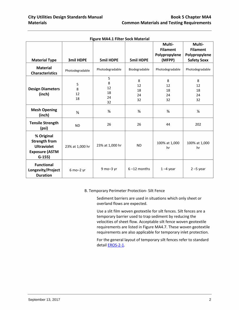
Sediment barriers are used in situations which only sheet or overland flows are expected. Figure MA4.1 lists available material types. The required diameter is project specific.
For the general layout of filter socks refer to standard detail EROS-2-2.
Filter socks are filled with a compost or mulch and shall meet the following requirements.
Compost shall be well decomposed, stable and weed free.
Variable particle size with maximum dimensions of (2’ L x ½” W x ½” D)
Refuse free (less than 1% by weight) Free of any contaminates and materials toxic to plant
growth pH of 5.5 to 8.0 Carbon-Nitrogen ratio not to exceed 100
The following are acceptable filter sock products:
Filtrexx Sediment Control Soxx Or engineer approved equal
City Utilities Design Standards Manual Book 5 Chapter MA4 Materials Common Materials and Testing Requirements
September 13, 2017 2
Figure MA4.1 Filter Sock Material
Material Type 3mil HDPE 5mil HDPE 5mil HDPE
Multi-Filament
Polypropylene (MFPP)
Multi-Filament
Polypropylene Safety Soxx
Material Characteristics
Photodegradable Photodegradable Biodegradable Photodegradable Photodegradable
Design Diameters (inch)
5 8
12 18
5 8
12 18 24 32
8 12 18 24 32
8 12 18 24 32
8 12 18 24 32
Mesh Opening (inch) ⅜ ⅜ ⅜ ⅜ ⅛
Tensile Strength (psi) ND 26 26 44 202
% Original Strength from
Ultraviolet Exposure (ASTM
G-155)
23% at 1,000 hr 23% at 1,000 hr ND 100% at 1,000 hr
100% at 1,000 hr
Functional Longevity/Project
Duration 6 mo–2 yr 9 mo–3 yr 6 –12 months 1 –4 year 2 –5 year
B. Temporary Perimeter Protection- Silt Fence
Sediment barriers are used in situations which only sheet or overland flows are expected.
Use a slit film woven geotextile for silt fences. Silt fences are a temporary barrier used to trap sediment by reducing the velocities of sheet flow. Acceptable silt fence woven geotextile requirements are listed in Figure MA4.7. These woven geotextile requirements are also applicable for temporary inlet protection.
For the general layout of temporary silt fences refer to standard detail EROS-2-1.
City Utilities Design Standards Manual Book 5 Chapter MA4 Materials Common Materials and Testing Requirements
September 13, 2017 3
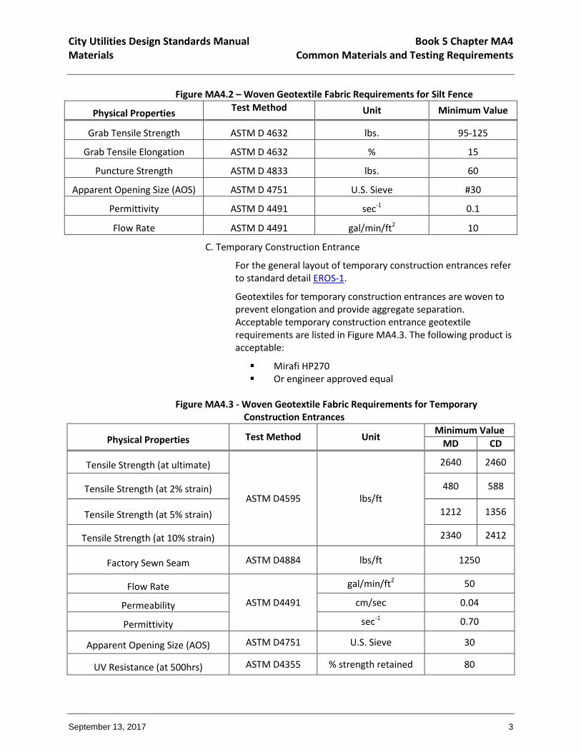
Figure MA4.2 – Woven Geotextile Fabric Requirements for Silt Fence
Physical Properties Test Method Unit Minimum Value
Grab Tensile Strength ASTM D 4632 lbs. 95-125
Grab Tensile Elongation ASTM D 4632 % 15
Puncture Strength ASTM D 4833 lbs. 60
Apparent Opening Size (AOS) ASTM D 4751 U.S. Sieve #30
Permittivity ASTM D 4491 sec-1 0.1
Flow Rate ASTM D 4491 gal/min/ft2 10
C. Temporary Construction Entrance
For the general layout of temporary construction entrances refer to standard detail EROS-1.
Geotextiles for temporary construction entrances are woven to prevent elongation and provide aggregate separation. Acceptable temporary construction entrance geotextile requirements are listed in Figure MA4.3. The following product is acceptable:
Mirafi HP270 Or engineer approved equal
Figure MA4.3 - Woven Geotextile Fabric Requirements for Temporary Construction Entrances
Physical Properties Test Method Unit Minimum Value MD CD
Tensile Strength (at ultimate)
ASTM D4595 lbs/ft
2640 2460
Tensile Strength (at 2% strain) 480 588
Tensile Strength (at 5% strain) 1212 1356
Tensile Strength (at 10% strain) 2340 2412
Factory Sewn Seam ASTM D4884 lbs/ft 1250
Flow Rate ASTM D4491
gal/min/ft2 50
Permeability cm/sec 0.04
Permittivity sec-1 0.70
Apparent Opening Size (AOS) ASTM D4751 U.S. Sieve 30
UV Resistance (at 500hrs) ASTM D4355 % strength retained 80
City Utilities Design Standards Manual Book 5 Chapter MA4 Materials Common Materials and Testing Requirements
September 13, 2017 4
Base aggregate material shall consist of INDOT #2 aggregate and capped with INDOT #5 aggregate. For aggregate requirements refer to Figure MA4.9.
The temporary construction entrance shall not impede or block current stormwater flow. If the site has current site drainage that must be maintained, install a drainage culvert in the temporary construction entrance. Acceptable culvert pipe materials are listed in Chapter MA5 - Gravity Storm Sewer Materials.
The minimum allowable size for a temporary construction culvert is 15-inches.
3. Concrete Washout Area
A concrete washout location shall be designated and a system shall be implemented to reduce the discharge of pollutants associated with concrete washout waste.
Standard details EROS-3-1 and EROS-3-2 illustrates concrete wash out requirements for below and above grade applications.
A. Common Concrete Washout Area
Place signage in area to designate location of concrete washout system.
Use a pit or bermed area designed and maintained at a capacity to contain all liquid and concrete waste generated by washout operations, between scheduled cleanout periods.
Line pit with 10-mm thick polyethylene lining to control seepage.
B. Prefabricated Concrete Washout Area
Prefabricated concrete washout areas may be acceptable; refer to manufacturer’s requirements.
4. Erosion Control Blankets
The following erosion control blankets are acceptable for use on areas with a 2:1 slope or less. For slopes steeper than 2:1 and installation longer than 12 months, coordinate with City Utilities.
Standard details EROS-4-1, EROS-4-2, and EROS-4-3 illustrates erosion control blanket installations for channel, slope and shoreline applications.
A. Short Term Erosion Control Blankets
Short term blankets are intended for installations of less than 6 months.
Blankets are composed of 100% straw fiber matrix, stitched with a photodegradable thread. The blanket is made of double-net construction.
City Utilities Design Standards Manual Book 5 Chapter MA4 Materials Common Materials and Testing Requirements
September 13, 2017 5
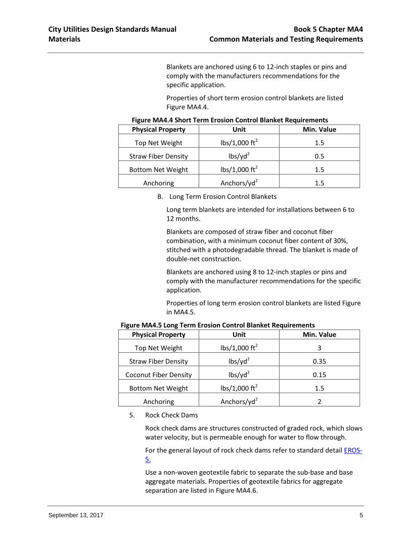
Blankets are anchored using 6 to 12-inch staples or pins and comply with the manufacturers recommendations for the specific application.
Properties of short term erosion control blankets are listed Figure MA4.4.
Figure MA4.4 Short Term Erosion Control Blanket Requirements Physical Property Unit Min. Value
Top Net Weight lbs/1,000 ft2 1.5
Straw Fiber Density lbs/yd2 0.5
Bottom Net Weight lbs/1,000 ft2 1.5
Anchoring Anchors/yd2 1.5
B. Long Term Erosion Control Blankets
Long term blankets are intended for installations between 6 to 12 months.
Blankets are composed of straw fiber and coconut fiber combination, with a minimum coconut fiber content of 30%, stitched with a photodegradable thread. The blanket is made of double-net construction.
Blankets are anchored using 8 to 12-inch staples or pins and comply with the manufacturer recommendations for the specific application.
Properties of long term erosion control blankets are listed Figure in MA4.5.
Figure MA4.5 Long Term Erosion Control Blanket Requirements Physical Property Unit Min. Value
Top Net Weight lbs/1,000 ft2 3
Straw Fiber Density lbs/yd2 0.35
Coconut Fiber Density lbs/yd2 0.15
Bottom Net Weight lbs/1,000 ft2 1.5
Anchoring Anchors/yd2 2
5. Rock Check Dams
Rock check dams are structures constructed of graded rock, which slows water velocity, but is permeable enough for water to flow through.
For the general layout of rock check dams refer to standard detail EROS-5.
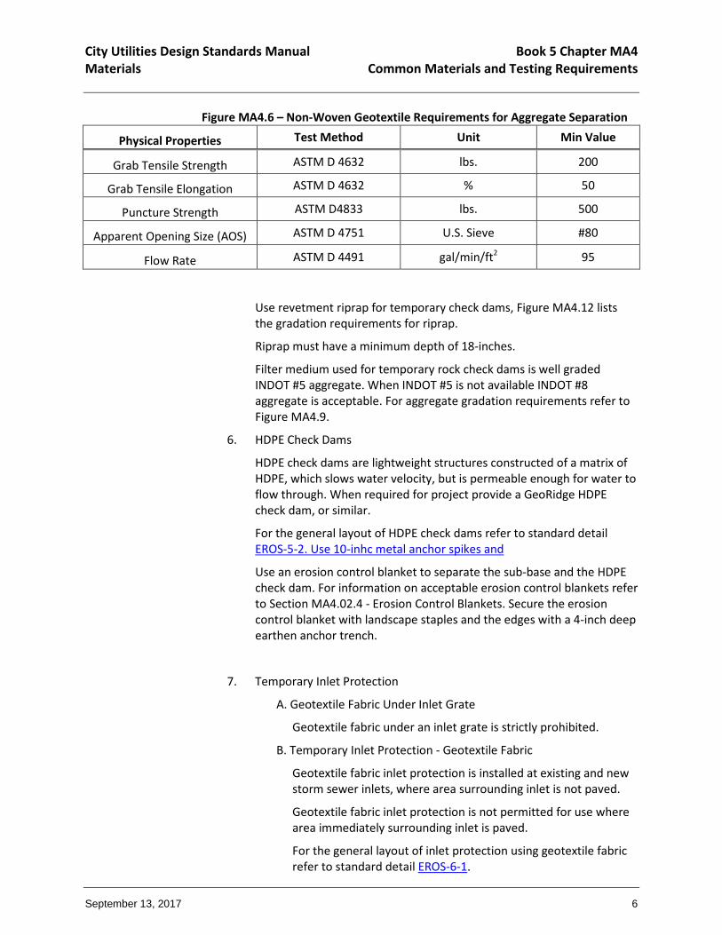
Use a non-woven geotextile fabric to separate the sub-base and base aggregate materials. Properties of geotextile fabrics for aggregate separation are listed in Figure MA4.6.
City Utilities Design Standards Manual Book 5 Chapter MA4 Materials Common Materials and Testing Requirements
September 13, 2017 6
Figure MA4.6 – Non-Woven Geotextile Requirements for Aggregate Separation
Physical Properties Test Method Unit Min Value
Grab Tensile Strength ASTM D 4632 lbs. 200
Grab Tensile Elongation ASTM D 4632 % 50
Puncture Strength ASTM D4833 lbs. 500
Apparent Opening Size (AOS) ASTM D 4751 U.S. Sieve #80
Flow Rate ASTM D 4491 gal/min/ft2 95
Use revetment riprap for temporary check dams, Figure MA4.12 lists the gradation requirements for riprap.
Riprap must have a minimum depth of 18-inches.
Filter medium used for temporary rock check dams is well graded INDOT #5 aggregate. When INDOT #5 is not available INDOT #8 aggregate is acceptable. For aggregate gradation requirements refer to Figure MA4.9.
6. HDPE Check Dams
HDPE check dams are lightweight structures constructed of a matrix of HDPE, which slows water velocity, but is permeable enough for water to flow through. When required for project provide a GeoRidge HDPE check dam, or similar.
For the general layout of HDPE check dams refer to standard detail EROS-5-2. Use 10-inhc metal anchor spikes and
Use an erosion control blanket to separate the sub-base and the HDPE check dam. For information on acceptable erosion control blankets refer to Section MA4.02.4 - Erosion Control Blankets. Secure the erosion control blanket with landscape staples and the edges with a 4-inch deep earthen anchor trench.
7. Temporary Inlet Protection
A. Geotextile Fabric Under Inlet Grate
Geotextile fabric under an inlet grate is strictly prohibited.
B. Temporary Inlet Protection - Geotextile Fabric
Geotextile fabric inlet protection is installed at existing and new storm sewer inlets, where area surrounding inlet is not paved.
Geotextile fabric inlet protection is not permitted for use where area immediately surrounding inlet is paved.
For the general layout of inlet protection using geotextile fabric refer to standard detail EROS-6-1.
City Utilities Design Standards Manual Book 5 Chapter MA4 Materials Common Materials and Testing Requirements
September 13, 2017 7
Structures are constructed to a height 12 to 18-inches above the top of the storm drain inlet, with a maximum post spacing of 36-inches.
Properties of woven geotextiles fabrics are listed in Figure MA4.2.
Structures shall be constructed and braced as required to withstand 1½-inches head of sediment without collapsing or undercutting.
Use of pre-manufactured and site constructed structures, that meet these requirements are acceptable.
C. Temporary Inlet Protection - Sediment Control Sack
Temporary sediment control sack inlet protection is installed at existing and new storm sewer inlets, where area surrounding inlet is paved.
Temporary sediment control sack inlet protection is not permitted for use where area immediately surrounding inlet is not paved.
For the general layout of inlet protection using sediment control sacks refer to standard detail EROS-6-2.
Proprietary inlet protection devices shall provide a filtering efficiency that removes at least 80% of the Total Suspended Solids (TSS).
Temporary sediment control devices include framework or basket that filters the stormwater runoff.
Each device must include a bypass to allow stormwater to flow into the storm system during excessive storm events, and dumping straps to allow for ease of maintenance.
The frame or basket must fit into the inlet and be supported by the inlet grate, or storm sewer.
Each temporary sediment control sack shall be used for the specific type of inlet they were designed and recommended by the manufacturer.
D. Temporary Inlet Protection - Stone Bags
Temporary stone bags are intended for use with a drainage area of ≤1 acre per inlet. Stone bag inlet protection is installed on existing and new storm sewer inlets and curb inlets, in both paved and un-paved areas.
Standard details EROS-6-3, EROS-6-4, and EROS-6-5 illustrates various stone bag installations.
Stone bag inlet structures are constructed to a height of 1 to 3 layers of bags, to a minimum height of 12-inches.
Stone bags made of non-woven geotextile fabric.
City Utilities Design Standards Manual Book 5 Chapter MA4 Materials Common Materials and Testing Requirements
September 13, 2017 8
Bags are filled with INDOT #5 washed aggregate. The aggregate must be larger than the storm sewer inlet grate openings. For aggregate gradation requirements refer to Figure MA4.9.
E. Temporary Inlet Protection - Filter Sock
Temporary filter socks are intended for use with a drainage area of ≤1 acre per inlet. Filter sock inlet protection is installed on existing and new storm sewer inlets and curb inlets, in both paved and un-paved areas.
For the general layout of inlet protection using filter socks refer to standard detail EROS-6-6.
For the material requirements of filter socks refer to section Figure MA4.1.
F. Temporary Inlet Protection - Straw Bales
For the general layout of inlet protection using straw bales refer to standard detail EROS-6-7.
Use straw bales that are wire-bound or string-tied.
G. Temporary Inlet Protection – Latex Bound Coir Mat
Temporary latex bound coir mats are intended for use with a drainage area of ≤1 acre per inlet. Mat inlet protection is installed on existing and new storm sewer inlets, in paved areas.
Provide mats that are comprised of 100-percent coir fiber bonded to a fiberglass mesh backing. Secure to the inlet using plastic zip ties.
For the general layout of inlet protection using filter socks refer to standard detail EROS-6-8.
8. Sediment Trap
Temporary sediment traps are intended for use with a drainage area of ≤5 acres. Traps are installed at the outlets of pipes, culverts, conduits, and channels.
For the general layout of sediment traps refer to standard detail EROS-7.
Use a non-woven geotextile fabric to separate the aggregate materials from the embankment. Figure MA4.6 lists the non-woven geotextile fabric requirements.
Use revetment riprap for temporary sediment traps, Figure MA4.12 lists the gradation requirements for riprap.
Riprap must have a minimum depth of 18-inches.
Filter medium used for temporary sediment traps is well graded INDOT #5 aggregate. When INDOT #5 is not available INDOT #8 aggregate is
City Utilities Design Standards Manual Book 5 Chapter MA4 Materials Common Materials and Testing Requirements
September 13, 2017 9
acceptable. For coarse aggregate gradation requirements refer to Figure MA4.9.
9. Temporary Sediment Control Dewatering Bag
Temporary sediment control dewatering bags are installed at the discharge point of all dewatering pipes and hoses.
Temporary sediment control dewatering bags are proprietary devices, coordinate with City Utilities for acceptable products.
Proprietary dewatering bags shall provide a filtering efficiency that removes at least 80% of the Total Suspended Solids (TSS).
For the general layout of dewatering bags refer to standard detail EROS-8.
Dewatering bags require an aggregate underlayment for stabilization. Use a non-woven geotextile fabric for separation of the subbase and aggregate underlayment. Figure MA4.6 list the geotextile material requirements.
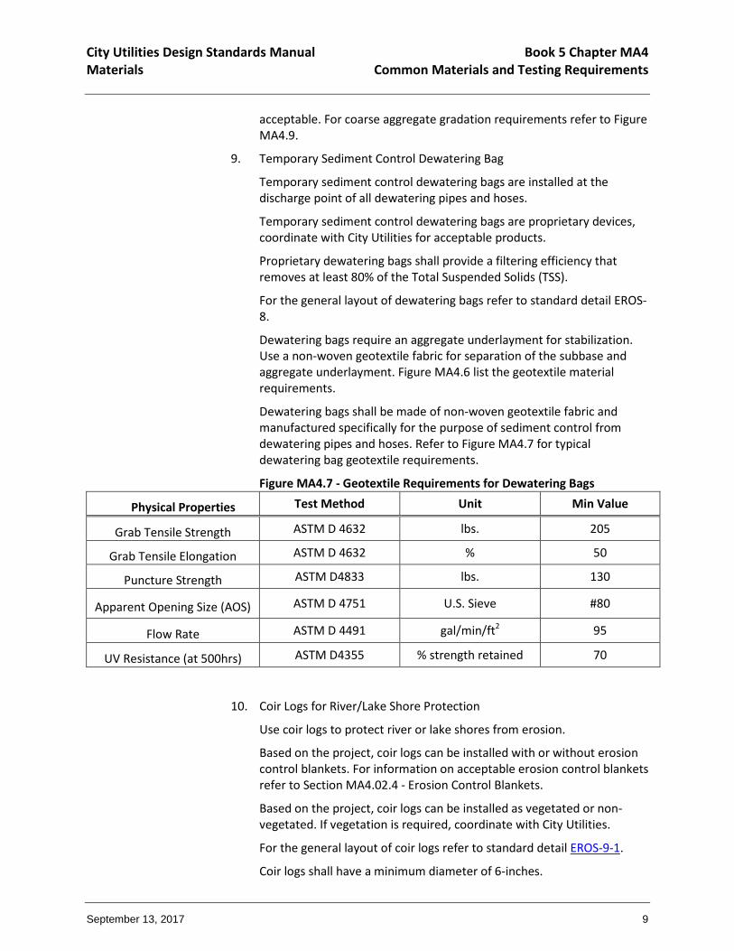
Dewatering bags shall be made of non-woven geotextile fabric and manufactured specifically for the purpose of sediment control from dewatering pipes and hoses. Refer to Figure MA4.7 for typical dewatering bag geotextile requirements.
Figure MA4.7 - Geotextile Requirements for Dewatering Bags
Physical Properties Test Method Unit Min Value
Grab Tensile Strength ASTM D 4632 lbs. 205
Grab Tensile Elongation ASTM D 4632 % 50
Puncture Strength ASTM D4833 lbs. 130
Apparent Opening Size (AOS) ASTM D 4751 U.S. Sieve #80
Flow Rate ASTM D 4491 gal/min/ft2 95
UV Resistance (at 500hrs) ASTM D4355 % strength retained 70
10. Coir Logs for River/Lake Shore Protection
Use coir logs to protect river or lake shores from erosion.
Based on the project, coir logs can be installed with or without erosion control blankets. For information on acceptable erosion control blankets refer to Section MA4.02.4 - Erosion Control Blankets.
Based on the project, coir logs can be installed as vegetated or non-vegetated. If vegetation is required, coordinate with City Utilities.
For the general layout of coir logs refer to standard detail EROS-9-1.
Coir logs shall have a minimum diameter of 6-inches.
City Utilities Design Standards Manual Book 5 Chapter MA4 Materials Common Materials and Testing Requirements
September 13, 2017 10
Coir logs for river/lake shore protection are made of 100% decorticated coconut fibers with a minimum density of 3½ lb/ft3.
Biodegradable netting with a life expectancy of ≥ 6 months shall be used.
11. Trackout Plates
Use metal track out plates, or rattle gates, as required to create temporary construction entrances the require the removal of dirt and debris from construction vehicles.
Size the grate to handle the anticipated construction loads and debris accumulation.
Conduct periodic maintenance of plates to remove debris build up.
12. Turf Reinforcement Mats
Use plastic turf reinforcement mats for temporary or permanent applications.
Provide a polymer type turf reinforcement mat called GeoRunner, or similar, as manufactured by Presto GeoSystems.
Unit Properties:
Material shall be constructed of polymer. Color shall be green. Color shall be uniform throughout all units in a pallet. Mats shall provide corrosion and chemical resistance.
Unit Dimensions:
Nominal Width shall be 24 inches. Nominal Length shall be 48.75 inches. Nominal Depth shall be 0.5 inches. Nominal Area shall be 8 ft2. Nominal mesh openings shall be 0.84 inches square. Mesh open area shall be 55% of total area. Nominal weight shall be 8 pounds.
Accessories:
Nylon, X-mas tree rivets shall be used to secure the panels together on the short end (2 feet). Three rivets are required for each panel. The rivets shall be 0.312 inches thick by 1.163 inches long.
Heat treated metal side clips are used to secure the panels together on the long end (4 feet). Two side clips are required for each panel to panel connection. The side clips shall be 22 gauge heat treated steel with zinc clear chromate plate.
The earth anchor consists of Duckbill® anchor, 3/32 galvanized cable, ferrule, Gripple® and anchor brace. Duckbill anchor break strength shall be 300 lb.
City Utilities Design Standards Manual Book 5 Chapter MA4 Materials Common Materials and Testing Requirements
September 13, 2017 11
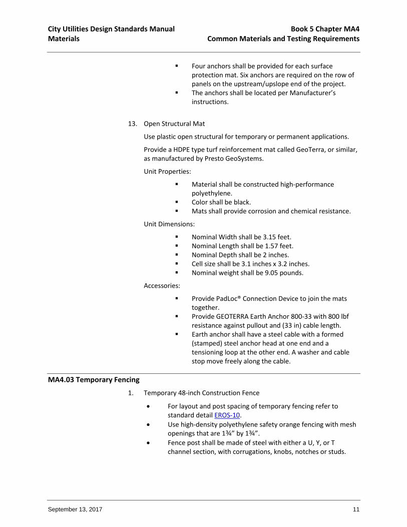
Four anchors shall be provided for each surface protection mat. Six anchors are required on the row of panels on the upstream/upslope end of the project.
The anchors shall be located per Manufacturer’s instructions.
13. Open Structural Mat
Use plastic open structural for temporary or permanent applications.
Provide a HDPE type turf reinforcement mat called GeoTerra, or similar, as manufactured by Presto GeoSystems.
Unit Properties:
Material shall be constructed high-performance polyethylene.
Color shall be black. Mats shall provide corrosion and chemical resistance.
Unit Dimensions:
Nominal Width shall be 3.15 feet. Nominal Length shall be 1.57 feet. Nominal Depth shall be 2 inches. Cell size shall be 3.1 inches x 3.2 inches. Nominal weight shall be 9.05 pounds.
Accessories:
Provide PadLoc® Connection Device to join the mats together.
Provide GEOTERRA Earth Anchor 800-33 with 800 lbf resistance against pullout and (33 in) cable length.
Earth anchor shall have a steel cable with a formed (stamped) steel anchor head at one end and a tensioning loop at the other end. A washer and cable stop move freely along the cable.
MA4.03 Temporary Fencing
1. Temporary 48-inch Construction Fence
• For layout and post spacing of temporary fencing refer to standard detail EROS-10.
• Use high-density polyethylene safety orange fencing with mesh openings that are 1¾” by 1¾”.
• Fence post shall be made of steel with either a U, Y, or T channel section, with corrugations, knobs, notches or studs.
City Utilities Design Standards Manual Book 5 Chapter MA4 Materials Common Materials and Testing Requirements
September 13, 2017 12
MA4.04 Concrete
This section covers projects with minor, uncomplicated concrete work. Intended for small general-use construction that does not include water retaining structures.
1. Quality Assurance
Listed below are typical quality assurance methods. Different requirement may be needed based on the project.
A. Concrete Testing Laboratory Qualifications:
All standard tests shall be conducted by an approved independent laboratory and will be made at the expense of the contractor, unless specifically noted otherwise.
Testing agency shall be in accordance with ASTM E329 and ASTM C1077.
Testing laboratory shall have been inspected and passed within previous two years by Cement and Concrete Reference Laboratory (CCRL) of NIST for: testing concrete aggregates, and for preparing and testing concrete trial batches with or without admixtures. Testing laboratory shall provide documentation indicating how deficiencies, if any, in most recent CCRL inspection report were corrected.
Selection of testing laboratory is subject to City’s acceptance.
B. Concrete Material Testing:
The cement, fine aggregate, coarse aggregate and reinforcing steel used shall be tested in accordance with the ASTM and specification for the type and class of material indicated. The manufacturer’s certificate of tests will generally be accepted.
C. Laboratory Trial Batch Testing
Where more than 100 cubic yards of concrete are required for the entire Project, advance tests of each concrete mix design used shall be made by an independent laboratory in accordance with ASTM C39 and ASTM C33. Perform the following testing on each trial batch:
Aggregate gradation for fine and coarse aggregates Slump Air content Compressive strength based on 8 cylinders of each mix
design; 4 tested at 7 days and 4 tested at 28 days Water content for mix designs shall be varied to
produce values for water to content-strength curves
Submit for each trial batch the following information:
Project identification name and number (if applicable)
City Utilities Design Standards Manual Book 5 Chapter MA4 Materials Common Materials and Testing Requirements
September 13, 2017 13
Date of test report Complete identification of aggregate source of supply Tests of aggregates for compliance with the Contract
Documents Scale weight of each aggregate Absorbed water in each aggregate Brand, type, and composition of cementitious materials Brand, type, and amount of each admixture Amounts of water used in trial mixes Proportions of each material per cubic yard Gross weight and yield per cubic yard of trial mixtures Measured slump Measured air content Compressive strength developed at 7 days and 28 days,
from not less than 4 test cylinders cast for each 7 day and 28-day test, and for each design mix
D. Certification of Concrete Mix
The requirement for trial batch will be waived upon compliance with requirements of this Paragraph. Verify compressive strength of each specified mix by data from series of at least 30 consecutive tests that have been made within previous 12 months. Test is the average strength of all specimens of the same age fabricated from sample taken from a single batch of concrete. Tests shall have been made on concrete with identical mix design to mix design proposed for the project, including sources of aggregate and manufacturers of cementitious materials and admixtures. Tests shall average above specified strength with no individual test falling more than 500 psi below specified strength and no three consecutive tests averaging below specified strength. Standard deviation for series of tests shall not exceed 640 psi in accordance with ACI 214.
2. Field Quality Control
Listed below is typical quality control methods different requirement may be needed based on the project.
A. Site Testing Services
Contractor shall employ independent testing laboratory to perform field quality control testing for concrete. Engineer will direct where Samples are obtained.
Testing laboratory will provide all labor, material, and equipment required for sampling and testing concrete, including: scale, glass tray, cones, rods, molds, air tester, thermometer, and other incidentals required.
Contractor shall provide curing and necessary cylinder storage. Actual curing in the structure shall be closely paralleled.
City Utilities Design Standards Manual Book 5 Chapter MA4 Materials Common Materials and Testing Requirements
September 13, 2017 14
B. Quality Control Testing During Construction
Perform sampling and testing for field quality control during concrete placing, as follows:
Sampling Fresh Concrete: ASTM C172 Slump: ASTM C143/C143M; one test for each concrete
load at point of discharge Concrete Temperature: ASTM C1064; one for every two
concrete loads at point of discharge, and when a change in the concrete is observed. Test each load when time from batching to placement exceeds 75 minutes.
Air Content: ASTM C231; one for every two concrete load at point of discharge, and when a change in the concrete is observed.
Unit Weight: ASTM C138; one for every two concrete loads at point of discharge, and when a change in the concrete is observed.
Compression Test Specimens: In accordance with ASTM C31, make one set of compression cylinders for each 50 yd3 of concrete, or fraction thereof, of each mix design placed each day. Each set shall be four standard cylinders, unless otherwise directed by Engineer.
C. Cold Weather Placing:
1. Protect concrete Work from physical damage or reduced strength that could be caused by frost, freezing, or low temperatures, in compliance with ACI 306R and the Contract Documents.
2. When air temperature has fallen to or may be expected to fall below 40 degrees F, provide adequate means to maintain temperature in area where concrete is being placed between 50 degrees F and 70 degrees F for a period of seventy-two hours after placing. Provide temporary housings or coverings including tarpaulins or plastic film. Maintain temporary heating and protection as necessary so that ambient temperature does not fall more than 30 degrees F in the 24 hours following the seventy-two hour period. Avoid rapid dry out of concrete due to overheating, and avoid thermal shock due to sudden cooling or heating.
3. When air temperature has fallen to or is expected to fall below 40 degrees F, uniformly heat water and aggregates before mixing for concrete as required to obtain concrete mixture temperature not less than 70 degrees F and not more than 90 degrees F at point of placement.
4. Do not use frozen materials or materials containing ice or snow. Do not place concrete on frozen subgrade or on subgrade
City Utilities Design Standards Manual Book 5 Chapter MA4 Materials Common Materials and Testing Requirements
September 13, 2017 15
containing frozen materials. Before placing concrete, verify that forms, reinforcing, and adjacent concrete surfaces are entirely free of frost, snow, and ice.
5. Do not use salt or other materials containing antifreeze agents. Do not use chemical accelerators or set control admixtures unless approved by Engineer and tested in mix design proposed for use.
6. During pouring and curing periods, a permanent temperature record shall be kept showing the date, hour outside temperature at several points within the enclosure to show the most favorable and unfavorable conditions to which the concrete is subjected. Thermometer readings shall be taken at the start of Work in the morning and again in the late afternoon, and the data so obtained shall be recorded in such a manner that it will show the location of each reading and any conditions which might have an effect on the temperature. A copy of the temperature record shall be made available to the Engineer.
7. Before concreting any section of a structure, the section shall be completely housed or enclosed in a manner that will provide the maintenance of the specified temperatures. The housing shall be left in place for the curing period specified. except that sections may be temporarily removed as required to accommodate the placing of column forms or concrete, provided that they are replaced immediately after the form or concrete is in its final position.
8. In placing floor slabs, tarpaulins supported on horses or other framework shall follow closely the placing of the concrete so that only a few feet of the finished slab is exposed to the outside atmosphere at any one time. Such tarpaulins shall be arranged so that the heated air from the space below can circulate freely in the space between the tarpaulin and the freshly placed concrete. If necessary, in order to maintain the proper temperature between the slab and the tarpaulins, temporary openings may be left in the floor and forms to facilitate the circulation of warm air in this space. Such openings shall not exceed 18 inches in their greatest dimension.
9. Top covers may be removed between the hours of 8:00 a.m. and 5:00 p.m. on days when the temperature is above 35 degrees F to permit erection of forms, but they shall be replaced not later than 5:00 p.m.
10. Within the enclosure, such means of artificial heat shall be provided as will maintain the temperatures specified continuously and with reasonable degree of uniformity in all parts of the enclosure. All exposed concrete surfaces within the heated area shall be wet with a hose stream at least once every
City Utilities Design Standards Manual Book 5 Chapter MA4 Materials Common Materials and Testing Requirements
September 13, 2017 16
24 hours during the hardening period, except where a stream curing is provided.
11. The Contractor shall provide adequate fire protection accessible at all times where heating is in progress and shall maintain watchmen or other attendants to keep the heating units in continuous operation.
12. Heating appliances shall not be placed in such a manner as to endanger form work or centering or expose any area of concrete to drying out or other injury due to excessive temperatures.
D. Hot Weather Placing:
1. When hot weather conditions exist that would impair the quality and strength of concrete, place concrete in compliance with ACI 305R and the Contract Documents.
2. When ambient air temperature is at or above 90 degrees F and rising, cool ingredients before mixing concrete to maintain concrete temperature at time of placement below 80 degrees F. When ambient air temperature is at or above 90 degrees F and falling, cool the ingredients before mixing concrete to maintain concrete temperature at time of placement below 85 degrees F. In no case shall the concrete temperature at time of placement exceed 90 degrees F.
3. Mixing water may be chilled, or chopped ice may be used to control concrete temperature provided the water equivalent of ice is calculated in total amount of mixing water. If required, reduce the time from addition of mix water to placement, or use set-retarding admixture.
4. Cover reinforcing materials with water soaked burlap if ambient air temperature becomes too hot, so that reinforcing material temperature does not exceed ambient air temperature immediately before embedment of reinforcing in concrete.
5. Wet forms thoroughly before placing concrete.
6. Do not place concrete at temperature that causes difficulty from loss of slump, flash set, or cold joints.
7. Do not use set control admixtures unless approved by Engineer in mix design.
8. Obtain Engineer's approval of substitute methods and materials proposed for use.
3. Cementations Material
Portland cement Type I or Type I/II produced per ASTM C150 is typically used. Type II cement is also acceptable and used when the concrete is subject to corrosive environments. Type II cement adds corrosion resistance to the concrete.
City Utilities Design Standards Manual Book 5 Chapter MA4 Materials Common Materials and Testing Requirements
September 13, 2017 17
4. Aggregates
Aggregates for concrete shall conform to ASTM C33, Class Designation 4S. The designation is based on a Northern weather region.
Aggregates containing soluble salts or other substances, such as iron, sulfides, pyrite, marcasite, ochre or other materials that can cause stains on exposed concrete are not acceptable.
A. Fine Aggregate
Fine aggregate is clean, sharp natural sand that is free of loam, clay, lumps and other deleterious substances.
Dune sand, bank run sand and manufactured sand is unacceptable.
5. Water
Water used in producing and curing concrete shall be clean and free of injurious quantities of oils, acids, alkalis, organic materials and other substances that may be deleterious to concrete and steel
6. Concrete Admixtures
The American Concrete Institute (ACI) 116R-00 defines concrete admixture as “a material other than, water, aggregates, hydraulic cement, and fiber reinforcement, used as an ingredient of a cementations mixture to modify its freshly mixed, setting, or hardened properties and that is added to the batch before or during its mixing.” Admixtures are chemicals that are used to improve concrete performance. Listed below are acceptable concrete admixtures.
Admixtures shall be compatible with each other. Admixtures shall not contain thiocyanates, shall not contain more than 0.05 percent chloride ion, and shall be non-toxic in the concrete mix after 30 days. Do not use admixtures that have not been incorporated and tested in the accepted mixes, unless otherwise approved by engineer.
A. Air Entraining Admixtures: ASTM C260.
Air entraining admixture shall be vinsol resin or vensol rosin-based.
B. Water Reducing Admixture: ASTM C494, Type A.
Proportion Class “A”, and Class “B” concrete with non-air-entraining, normal setting, water reducing, aqueous solution of modified organic polymer. Admixture shall not contain lignin, nitrates, or chlorides added during manufacturing.
C. High Range Water Reducing Admixture (HRWR): ASTM C494, Type F/G.
Use high range water reducing admixture in the concrete classifications so specified or indicated. When used, HRWR admixture shall be added to concrete in accordance with admixture manufacturer’s published instructions.
City Utilities Design Standards Manual Book 5 Chapter MA4 Materials Common Materials and Testing Requirements
September 13, 2017 18
D. Set Control Admixtures: In accordance with ASTM C494. Use the following as required:
Type B, Retarding Type C, Accelerating Type D, Water-reducing and Retarding Type E, Water-reducing and Accelerating Type F, Water-reducing, high-range admixtures Type G, Water-reducing, high-range, and retarding
admixtures
E. Calcium Chloride: Do not use calcium chloride.
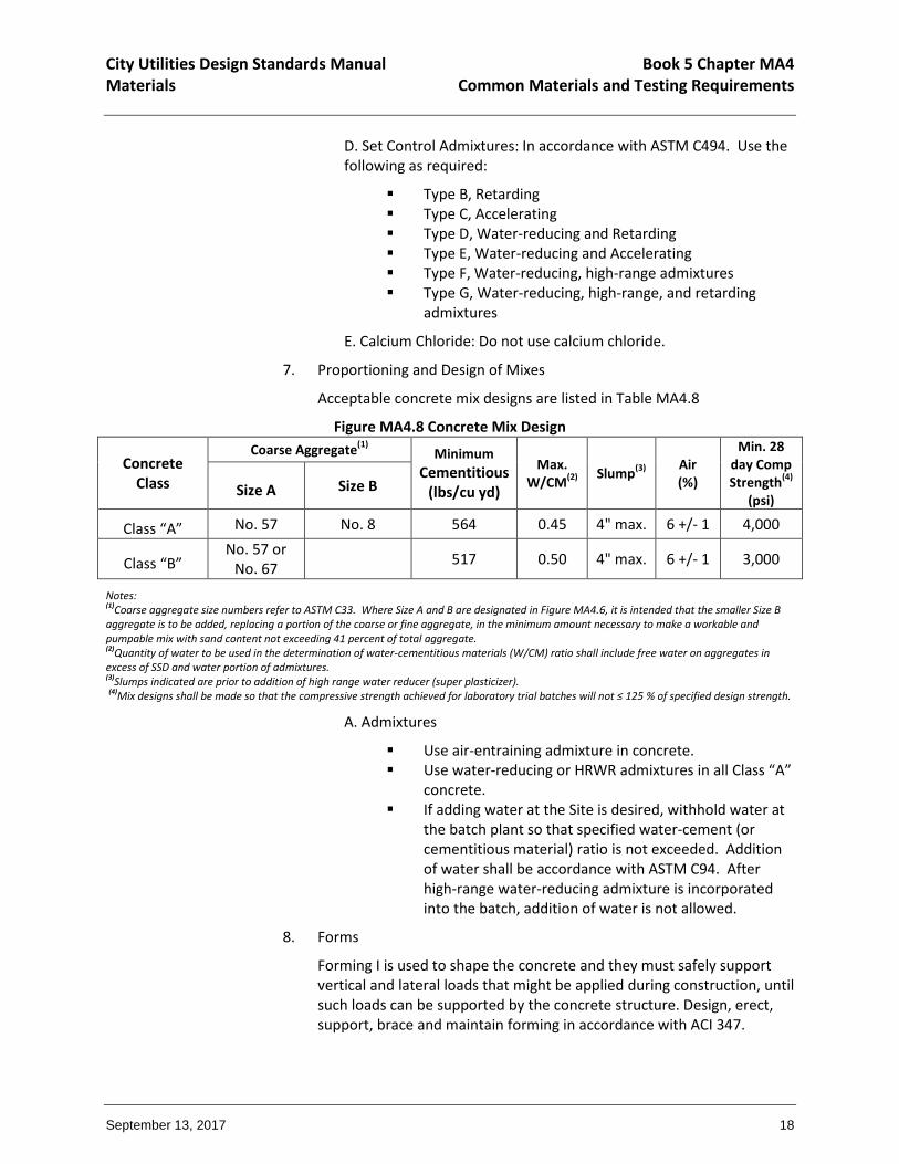
7. Proportioning and Design of Mixes
Acceptable concrete mix designs are listed in Table MA4.8
Figure MA4.8 Concrete Mix Design
Concrete Class
Coarse Aggregate(1) Minimum Cementitious
(lbs/cu yd)
Max. W/CM(2) Slump(3) Air
(%)
Min. 28 day Comp Strength(4)
(psi) Size A Size B
Class “A” No. 57 No. 8 564 0.45 4" max. 6 +/- 1 4,000
Class “B” No. 57 or
No. 67 517 0.50 4" max. 6 +/- 1 3,000
Notes: (1)Coarse aggregate size numbers refer to ASTM C33. Where Size A and B are designated in Figure MA4.6, it is intended that the smaller Size B aggregate is to be added, replacing a portion of the coarse or fine aggregate, in the minimum amount necessary to make a workable and pumpable mix with sand content not exceeding 41 percent of total aggregate. (2)Quantity of water to be used in the determination of water-cementitious materials (W/CM) ratio shall include free water on aggregates in excess of SSD and water portion of admixtures. (3)Slumps indicated are prior to addition of high range water reducer (super plasticizer). (4)Mix designs shall be made so that the compressive strength achieved for laboratory trial batches will not ≤ 125 % of specified design strength.
A. Admixtures
Use air-entraining admixture in concrete. Use water-reducing or HRWR admixtures in all Class “A”
concrete. If adding water at the Site is desired, withhold water at
the batch plant so that specified water-cement (or cementitious material) ratio is not exceeded. Addition of water shall be accordance with ASTM C94. After high-range water-reducing admixture is incorporated into the batch, addition of water is not allowed.
8. Forms
Forming I is used to shape the concrete and they must safely support vertical and lateral loads that might be applied during construction, until such loads can be supported by the concrete structure. Design, erect, support, brace and maintain forming in accordance with ACI 347.
City Utilities Design Standards Manual Book 5 Chapter MA4 Materials Common Materials and Testing Requirements
September 13, 2017 19
A. Forms for Smooth Finish Concrete
Forms for smooth finish concrete are constructed with plywood, metal, metal-framed plywood-faced, or other panel type materials.
Acceptable form surfaces are continuous, straight, smooth as-cast with no wood grain or other surface texture imparted by forming.
Use forming, in largest practical sizes, which minimize the number of joints; and material with sufficient thickness to withstand pressure of newly placed concrete without bowing or deflection.
B. Forms for Standard Finish Concrete
Forms for smooth finish concrete are constructed with plywood, lumber, or metal.
Lumber used for forming must be dressed on at least 2 edges and 1 side.
C. Form Ties
Form ties used for small concrete projects are typically snap ties, removable ties are available but not commonly used.
Use factory-fabricated metal from ties, designed to prevent form deflection, and to prevent spalling of concrete surfaces upon removal.
Holes left behind on the concrete surface from form ties shall be no larger than 1-inch in diameter
Use ties with waterstops on all exterior, below-grade walls, and walls subject to hydrostatic pressure
Do not use wire ties.
D. Forms Coatings
Forms shall be coated in commercial formulated form-coating compounds that will not bond with, satin, nor adversely affect concrete surfaces, and will not impair subsequent treatment of concrete surfaces requiring bond or adhesion, nor impede wetting of surfaces to be cured with water or curing compounds.
Use mineral oil based coatings when concrete surfaces will be in contact with potable water or water that will be treated to become potable.
9. Reinforcing Materials
A. Reinforcing Bars
Use reinforcing bars that are manufactured in accordance with ASTM A615, Grade 60 deformed bars.
City Utilities Design Standards Manual Book 5 Chapter MA4 Materials Common Materials and Testing Requirements
September 13, 2017 20
B. Welded Wire Fabric
Use welded wire fabric that is manufactured in accordance with ASTM A185, Grade 60 deformed bars.
C. Reinforcing Supports
Use reinforcing supports including bolsters, chairs, spacers, and other devices for spacing, supporting and fastening reinforcing in pace.
Use wire bar-type supports complying with CRSI MSP1 recommendations, except as specified in this Section. Do not use wood, brick, or other unacceptable materials.
For slabs on grade, use precast concrete blocks, four inches square minimum with compressive strength equal to or greater than the surrounding concrete, or supports with sand plates or horizontal runners where base materials will not support chair legs.
For all concrete surfaces where legs of supports are in contact with forms, provide supports having either hot-dip galvanized, plastic-protected, or stainless steel legs in accordance with CRSI MSP1.
Provide precast concrete supports over waterproof membranes.
D. Adhesive Dowels
Adhesive dowels are reinforcement used after the concrete has set. Typically, they are used for the connection of masonry walls to an existing concrete wall. A hole is drilled into the existing concrete and a project specific adhesive is used to bind the dowel to the concrete. The adhesive dowels reinforce the connection between the existing concrete and masonry wall. Adhesive is not specified because it is based on project specific requirements.
Use dowel reinforcing bars manufactured in accordance with ASTM A615, Grade 60.
10. Related Materials
A. PVC Waterstops
PVC waterstops that comply with CRD-C572 are acceptable. Do not use reclaimed or scrap material.
The following manufacturers of PVC waterstops are acceptable: 1. W.R. Meadows, Inc. 2. Greenstreak Plastic Products Company. 3. Or approved equal.
The minimum thickness of waterstops is ⅜-inch.
City Utilities Design Standards Manual Book 5 Chapter MA4 Materials Common Materials and Testing Requirements
September 13, 2017 21
Each waterstops shall have a minimum of 7 ribs equally spaced at each end on each side with the first rib located at the edge. Each rib shall be minimum ⅛-inch in height.
Waterstops used for construction joints shall be 6-inch wide flat-strip type.
Waterstops used for expansion joints shall be 9-inches wide centerbulb type.
B. Hydrophilic Waterstops
Hydrophilic waterstop materials shall be bentonite-free and shall expand by minimum of 80 % of dry volume in the presence of water to form a watertight joint seal without damaging the concrete in which it is cast.
The following manufacturers of Hydrophilic Water Stops are acceptable::
1. Duroseal Gasket, by BBZ USA, Inc. 2. Adeka Ultraseal MC-2010M, by Asahi Denka
Kogyo K.K. 3. Hydrotite, by Greenstreak Plastic Products
Company. 4. Or approved equal.
Waterstop material shall be composed of resins and polymers that absorb water and cause a completely reversible and repeatable increase in volume.
Waterstop material shall be dimensionally stable after repeated wet-dry cycles with no deterioration of swelling potential.
Select material in accordance with manufacturer’s recommendations for type of liquid to be contained.
Minimum cross-sectional dimensions: 3/16-inch by ¾-inch.
Hydrophilic Sealant: Shall adhere firmly to concrete, metal, and PVC in dry or damp condition and be indefinitely elastic when cured. THe following manufacturers are acceptable:
1. Duroseal Paste, by BBZ USA, Inc. 2. Adeka Ultraseal P-201, by Asahi Denka Kogyo
K.K. 3. Hydrotite, by Greenstreak Plastic Products
Company. 4. Or approved equal.
C. Vapor Retarder
Vapor retarder must be compatible with other applied finishes. Refer to each manufacturer’s literature. Use caution with coordinating use of vapor retarder’s with the requirements of chemical resistant coatings and concrete hardeners.
City Utilities Design Standards Manual Book 5 Chapter MA4 Materials Common Materials and Testing Requirements
September 13, 2017 22
The following manufacturers of vapor retarders are acceptable:
1. Stego Wrap 10-mil Vapor Retarder, by Stego Industries LLC.
2. Griffolyn 10-mil, by Reef Industries. 3. Moistop Ultra, by Fortifiber Industries. 4. Or approved equal.
Vapor retarder membrane shall comply with the following:
1. Water Vapor Transmission Rate: ASTM E96: 0.04 perms or lower.
2. Water Vapor Retarder: ASTM E1745: Meets or exceeds Class C.
3. Thickness of Retarder (plastic): ACI 302 1R: Not less than 10 mils.
4. Provide accessories by same manufacturer as vapor retarder.
D. Concrete Curing Materials
Concrete curing methods must be compatible with any applied flooring finishes or treatments. Liquid membrane-forming curing compound must be compatible with other applied finishes. Refer to the curing compound manufacturer’s literature. Use caution when coordinating the use of curing compounds with the requirements of chemical-resistant coatings and concrete hardeners.
Absorptive Cover: Burlap cloth made from jute or kenaf, weighing approximately 10 oz/yd2 and complying with AASHTO M 182, Class 3.
Curing Mats: Shall be heavy carpets or cotton mats, quilted at 4” on centers, and weighing minimum of 12 oz/yd2 when dry.
Moisture-Retaining Cover: Provide one of the following, complying with ASTM C171:
1. Waterproof paper. 2. Polyethylene film. 3. White burlap polyethylene sheet.
Liquid Curing Compound: ASTM C309 Type 1-D (water retention requirements):
1. Provide fugitive dye. 2. Curing compound shall be applied by roller or
power sprayer. 3. If concrete is to be in contact with potable water
product shall be listed in NSF 61.
E. Epoxy Bonding Agent
Two-component epoxy resin bonding agent from the following manufactures are acceptable:
City Utilities Design Standards Manual Book 5 Chapter MA4 Materials Common Materials and Testing Requirements
September 13, 2017 23
1. Sikadur 32, Hi-Mod LPL, by Sika Corporation. 2. Eucopoxy LPL, by the Euclid Chemical Company. 3. Or approved equal.
F. Epoxy-Cement Bonding Agent
Three-component blended epoxy resin-cement bonding agent from the following manufactures are acceptable:
1. Sika Armatec 110 EpoCem, by Sika Corporation. 2. Duralprep A.C., by Euclid Chemical Company. 3. Or approved equal.
G. Preformed Expansion Joint Filler
Preformed expansion joint filler complying with ASTM D1752 Type I (sponge rubber) or Type II (cork) are acceptable:
H. Joint Sealant and Accessories used on Isolation Joints, Control Joints, and Expansion Joints
If joint sealants are to be used on water retaining structures or may be submerged in potable water, provide a separate joint sealant than listed below which has additional requirements.
For exterior and interior horizontal and vertical joints; submerged and intermittently submerged in wastewater use one of the following two-component Polyurethane Sealants:
1. Sikaflex- 2c NS by Sika Corporation. 2. Vulkem 227 by Tremco Sealant/Waterproofing
Division of RPM International, Inc. 3. Or approved equal.
For exterior and interior vertical joints; non-submerged use one of the following two-component Polyurethane sealants:
1. Sikaflex- 2c NS by Sika Corporation. 2. Dymeric 240 FC by Tremco
Sealant/Waterproofing Division of RPM International, Inc.
3. Or approved equal. For exterior and interior horizontal joints; non-
submerged, use one of the following two-component Polyurethane sealants:
1. Sikaflex- 2c SL by Sika Corporation. 2. THC/900 by Tremco Sealant/Waterproofing
Division of RPM International, Inc. 3. Or approved equal.
City Utilities Design Standards Manual Book 5 Chapter MA4 Materials Common Materials and Testing Requirements
September 13, 2017 24
11. Grout
A. Non-shrink Grout:
Use pre-packaged, non-metallic, cementitious grout requiring only the addition of water at the Site, with a minimum 28-day compressive strength of 7,000 psi.
The following products and manufactures are acceptable
1. NS Grout by Euclid Chemical Company. 2. Set Grout by Master Builders, Inc. 3. NBEC Grout by Five Star Products, Inc. 4. Or approved equal.
B. Epoxy Grout:
Used pre-packaged, non-shrink, non-metallic, 100% solids, solvent-free, moisture-insensitive, three-component epoxy grouting system.
Minimum Seven-day Compressive Strength: 14,000 psi, when tested in accordance with ASTM C579.
Products and Manufacturers: Provide one of the following:
1. Euco High Strength Grout, by Euclid Chemical Company.
2. Sikadur 42, Grout Pak, by Sika Corporation. 3. Five Star Epoxy Grout, by Five Star Products, Inc. 4. Or approved equal.
C. Grout Fill:
Grout mix shall consist of cement, fine and coarse aggregates, water, and admixtures complying with requirements specified in this Section for similar materials in concrete.
Proportion and mix grout fill as follows: 1. Minimum Cement Content: 564 lb/yd3. 2. Maximum Water-Cement Ratio: 0.45. 3. Maximum Coarse Aggregate size: ½-inch, unless
otherwise indicated. 4. Minimum 28-day Compressive Strength: 4,000
psi.
MA4.05 Bedding and Backfill
This section covers requirements for trench bedding and backfill used for linear utility projects.
1. Quality Assurance
A. Testing Services:
Testing of materials, testing for moisture content during placement and compaction of fill materials, and testing of
City Utilities Design Standards Manual Book 5 Chapter MA4 Materials Common Materials and Testing Requirements
September 13, 2017 25
compaction for compliance with technical requirements of these standards shall be performed by a testing laboratory. Testing shall conform to ASTM D422, ASTM D427, ASTM D1557, ASTM D 2166, ASTM D 698, and ASTM D4318.
Test proposed materials in the laboratory and/or field for compliance with these standards.
Perform field moisture content and density tests to verify that the specified compaction of backfill materials has been obtained.
Inspect and approve subgrades and fill layers are in compliance
Report test results to City Utilities.
B. Testing Frequency –Pre-Installation
1. Complete gradation tests in accordance with ASTM D422. Perform one test for every 1,000 yd3 of each of the following types of materials:
Pipe Bedding Material Special Backfill General Fill
2. Demonstrate the adequacy of compaction equipment and procedures before exceeding any of the following amounts of earthwork quantities:
200 linear feet of special backfill per lift. 10 yd3 of structural backfill. 100 yd3 of embankment work. 50 yd3 of base material.
If compaction fails to conform to the specified requirements, remove and replace the backfill at proper density or bring the density up to specified level by other means acceptable.
C. Testing Frequency – During Installation
The frequency confirmation tests shall be not less than as follows: Each test location for trenches shall include tests for each layer, type, or class of backfill from bedding to finish grade.
Use the following testing frequencies and intervals,
Trenches for Underground Facilities:
In Open Fields: Two locations every 1,000 linear feet. Along Dirt or Gravel Roads or Off Traveled Right-of-
Way: Two locations every 500 linear feet. Crossing Paved Roads: 2 locations along each crossing. Under pavement cuts or within 2-feet of pavement
edges: One location every 400 linear feet.
City Utilities Design Standards Manual Book 5 Chapter MA4 Materials Common Materials and Testing Requirements
September 13, 2017 26
For Structural Backfill:
On 30’ intervals on all sides of the structure for every compacted lift, but no less than one per lift on each side of the structure for structures less than 60’ long on a side.
In Embankment or Fill:
One per 1,000 ft2 on every compacted lift.
Base Material:
One per 1,000 ft2 on every compacted lift.
2. Quality Control
A. Compaction Density Requirements:
The degree of compaction required for all types of fills shall be 95% density as determined by the Modified Proctor Test. Compaction may be obtained by mechanically tamping the material in 6”lifts. Water “flooding” or “jetting” methods of compaction are prohibited unless a variance is obtained from CUE. Note that the lifts may change based on material and compaction techniques used. Material shall be moistened or aerated as necessary to provide the moisture content that will facilitate obtaining the specified compaction.
All fill must be wetted and thoroughly mixed to achieve, +2% or -1% of the optimum moisture content, with the following exceptions: On-site clayey soils optimum to plus 3%.
Natural undisturbed soils or compacted soil subsequently disturbed or removed by construction operations shall be replaced with materials compacted as specified above.
Complete field density tests, during each day of compaction work. If the tests indicate unsatisfactory compaction, provide the additional compaction necessary to obtain the specified degree of compaction.
When required complete compaction testing requirements for water services excavations within roadway. Compaction testing for water service excavations outside of roadway will be on an as need basis.
B. Replacement of Unacceptable Excavated Materials
In cases where over-excavation for the replacement of unacceptable soil materials is required, the excavation shall be backfilled to the required subgrade with Special Backfill material and thoroughly compacted as specified above. Sides of the excavation shall be sloped in accordance to the maximum inclinations specified for each structure location.
City Utilities Design Standards Manual Book 5 Chapter MA4 Materials Common Materials and Testing Requirements
September 13, 2017 27
3. Native Fill
Use soil materials for backfill and fill, free of rock or gravel larger than 3-inches in any dimension, debris, waste, frozen materials, vegetation and other organic matter and other deleterious materials. Previously excavated materials meeting these requirements may be used for backfill. Testing may be required for general backfill and fill materials.
The following paragraphs outline material requirements for native backfill and fill used for open cut excavations.
A. Native Fill
Materials acceptable for use as backfill against walls, foundations, underground ductbanks, and other structures shall be stockpiled native sandy clay or granular soils obtained from on-site excavations and which are uniformly mixed, contain no organic matter, nor contain rocks or fragments greater than 3-inches in size, nor have greater than 40% passing the 200 sieve.
The maximum expansion of on-site materials shall be 1.5% as performed on a sample remolded to approximately 95% of the maximum dry density as determined in accordance with ASTM D698 at 2% below optimum moisture content under a 100 psf surcharge pressure.
4. Special Backfill
Use special backfill for beneath structures, concrete slabs, and pavements to provide structural support.
• Special backfill for utility projects is in accordance with the Indiana Department of Transportation (INDOT) Standard Specifications latest edition, Sections 211 and 904.
• The material shall be acceptable quality, free from large or frozen lumps, wood, or other extraneous matter.
• Use # 53/73 aggregate for special backfill, refer to Figure MA4.5 for the gradation distribution.
• The aggregate shall be crushed stone or air-cooled blast furnace slag (ACBF), Class D or higher.
5. “B” Borrow
The use of “B” Borrow as defined in Indiana Department of Transportation (INDOT) Standard Specifications latest edition, Sections 211 and 904, is prohibited and requires a variance for use on Fort Wayne projects. Refer to Chapter GR3 - Variances for submittal procedures.
6. Bedding
Bedding for pipes and structures varies based on the material type used. The following lists acceptable bedding requirements. The material
City Utilities Design Standards Manual Book 5 Chapter MA4 Materials Common Materials and Testing Requirements
September 13, 2017 28
numbers are from INDOT’s gradation classifications for course graded aggregate. For more information refer to INDOT Standard Specification Section 904.03. For the gradation distribution requirements see Figure MA4.5.
A. Bedding for RCP
Refer to standard detail BS-4 for depths and thickness of the pipe bedding.
Compacted Granular Bedding Material:
The compacted granular bedding shall consist of angular ⅟4 to 1 ½-inch, graded stone.
INDOT Classification No. 5, No. 8 and No. 9 are acceptable.
Shaped Subgrade Bedding:
The shaped subgrade material shall be No. 8 crushed stone.
The compacted granular bedding shall consist of angular, ⅟4 to 1 ½-inch graded stone. INDOT Classification No. 5, No.8 or No. 9 are acceptable.
B. Bedding for Flexible Pipes
Flexible pipes include PVC, HDPE, CMP, FRP, DIP and PP refer to standard detail BS-5 for depths and thickness of the pipe bedding.
The compacted granular bedding material shall consist of angular, graded stone. INDOT Classification No. 5, No. 8, and No. 9 are acceptable.
C. Bedding for Precast Structures
Precast base sections for structures shall be placed on a well graded, compacted granular bedding material.
The compacted granular bedding material shall consist of angular, graded stone.
INDOT Classification No. 5, No. 8, No. 9, are acceptable.
7. Flowable FIll
Flowable fill may be utilized at utility crossings and other such instances, and be a self-compacting flowable cementitious concrete material.
Use flowable fill with 50 psi - 200 psi 28 day compressive strength when tested according to ASTM C495. In addition, the diameter of spread shall be greater than or equal to 8-inches.
Self-compacting flowable cementitious concrete material shall be produced from the following:.
• Cementitious material (Portland cement and flyash): 100 to 350 lbs
City Utilities Design Standards Manual Book 5 Chapter MA4 Materials Common Materials and Testing Requirements
September 13, 2017 29
• #23 washed sand: 2000 to 3000 lbs • Water: 30 to 40 lbs (water to cement ratio= 1.0 to 1.5) • Air: 10 to30% (Use Flowable Fill Performance Admixture –
Eucon Easy Fill or equal) • Maximum 200 psi compressive strength recommended
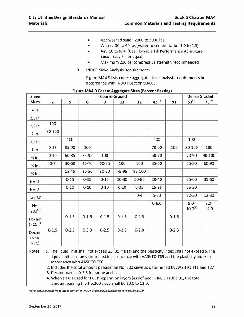
8. INDOT Sieve Analysis Requirements
Figure MA4.9 lists coarse aggregate sieve analysis requirements in accordance with INDOT Section 904.03.
Figure MA4.9 Coarse Aggregate Sizes (Percent Passing) Sieve Sizes
Coarse Graded Dense Graded 2 5 8 9 11 12 43(1) 91 53(1) 73(1)
4 in.
3½ in.
2½ in. 100
2 in. 80-100
1½ in. 100 100 100
1 in. 0-25 85-98 100 70-90 100 80-100 100
¾ in. 0-10 60-85 75-95 100 50-70 70-90 90-100
½ in. 0-7 30-60 40-70 60-85 100 100 35-50 55-80 60-90
⅜ in. 15-45 20-50 30-60 75-95 95-100
No. 4. 0-15 0-15 0-15 10-30 50-80 20-40 35-60 35-60
No. 8. 0-10 0-10 0-10 0-10 0-35 15-35 25-50
No. 30 0-4 5-20 12-30 12-30
No. 200(2)
0-6.0 5.0-10.0(4)
5.0-12.0
Decant (PCC)(3)
0-1.5 0-1.5 0-1.5 0-1.5 0-1.5 0-1.5
Decant (Non-PCC)
0-2.5 0-2.5 0.3.0 0-2.5 0-2.5 0-2.0 0-2.5
Notes: 1. The liquid limit shall not exceed 25 (35 if slag) and the plasticity index shall not exceed 5.The liquid limit shall be determined in accordance with AASHTO T89 and the plasticity index in accordance with AASHTO T90. 2. Includes the total amount passing the No. 200 sieve as determined by AASHTO T11 and T27 3. Decant may be 0-2.5 for stone and slag. 4. When slag is used for PCCP separation layers (as defined in INDOT) 302.01, the total amount passing the No.200 sieve shall be 10.0 to 12.0. Note: Table excerpt from latest edition of INDOT Standard Specification section 904.03(e).

City Utilities Design Standards Manual Book 5 Chapter MA4 Materials Common Materials and Testing Requirements
September 13, 2017 30
MA4.06 Geosynthetics for Earthwork
This section covers requirements for geosynthetics for earthwork, including requirements for woven and non-woven geotextiles and cellular confinement systems. Included is the material properties of various geosynthetics, and there intended application.
1. Geotextiles for Underdrains
Use a non-woven geotextile for protecting the underdrain from fine sediment clogging. Acceptable non-woven geotextile requirements are listed in Figure MA4.10.
Figure MA4.10 – Non-Woven Geotextile Requirements for Underdrains Physical Properties Test Method Unit Min Value
Grab Tensile Strength ASTM D 4632 lbs. 80
Grab Tensile Elongation ASTM D 4632 % 50
Trapezoid Tear Strength ASTM D 4533 lbs. 30
Permittivity ASTM D 4491 sec-1 2.1
Flow Rate ASTM D 4491 gal/min/ft2 155
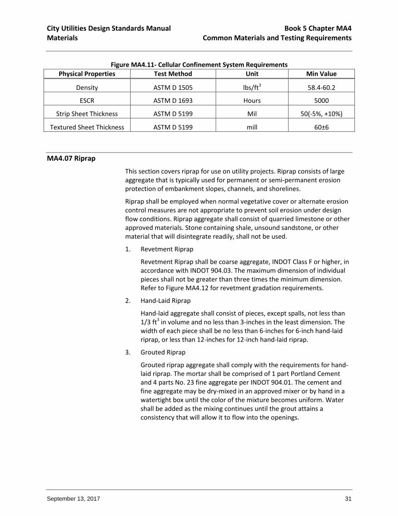
2. Cellular Confinement Systems
Cellular confinement systems are used to provide soil stabilization and turf protection. Figure MA4.11 list acceptable cellular confinement system properties. Acceptable cellular confinement systems include:
Geoweb Cellular Confinement System as manufactured by Presto Geosystems
Or engineer approved equal
A. Cell Properties
Cell GW20V Length = 8.8-inches Width = 10.2-inches Nominal Area= 44.8 in2 Nominal Depth= 6-inches
B. Stake Anchorage
ATRA Anchors- Standard ½ -inch steel reinforcing rod with an ATRA clip attached as an end cap.
C. Cell Infill Materials
INDOT #53 Stone over #8 stone.
City Utilities Design Standards Manual Book 5 Chapter MA4 Materials Common Materials and Testing Requirements
September 13, 2017 31
Figure MA4.11- Cellular Confinement System Requirements Physical Properties Test Method Unit Min Value
Density ASTM D 1505 lbs/ft3 58.4-60.2
ESCR ASTM D 1693 Hours 5000
Strip Sheet Thickness ASTM D 5199 Mil 50(-5%, +10%)
Textured Sheet Thickness ASTM D 5199 mill 60±6
MA4.07 Riprap
This section covers riprap for use on utility projects. Riprap consists of large aggregate that is typically used for permanent or semi-permanent erosion protection of embankment slopes, channels, and shorelines.
Riprap shall be employed when normal vegetative cover or alternate erosion control measures are not appropriate to prevent soil erosion under design flow conditions. Riprap aggregate shall consist of quarried limestone or other approved materials. Stone containing shale, unsound sandstone, or other material that will disintegrate readily, shall not be used.
1. Revetment Riprap
Revetment Riprap shall be coarse aggregate, INDOT Class F or higher, in accordance with INDOT 904.03. The maximum dimension of individual pieces shall not be greater than three times the minimum dimension. Refer to Figure MA4.12 for revetment gradation requirements.
2. Hand-Laid Riprap
Hand-laid aggregate shall consist of pieces, except spalls, not less than 1/3 ft3 in volume and no less than 3-inches in the least dimension. The width of each piece shall be no less than 6-inches for 6-inch hand-laid riprap, or less than 12-inches for 12-inch hand-laid riprap.
3. Grouted Riprap
Grouted riprap aggregate shall comply with the requirements for hand-laid riprap. The mortar shall be comprised of 1 part Portland Cement and 4 parts No. 23 fine aggregate per INDOT 904.01. The cement and fine aggregate may be dry-mixed in an approved mixer or by hand in a watertight box until the color of the mixture becomes uniform. Water shall be added as the mixing continues until the grout attains a consistency that will allow it to flow into the openings.
City Utilities Design Standards Manual Book 5 Chapter MA4 Materials Common Materials and Testing Requirements
September 13, 2017 32
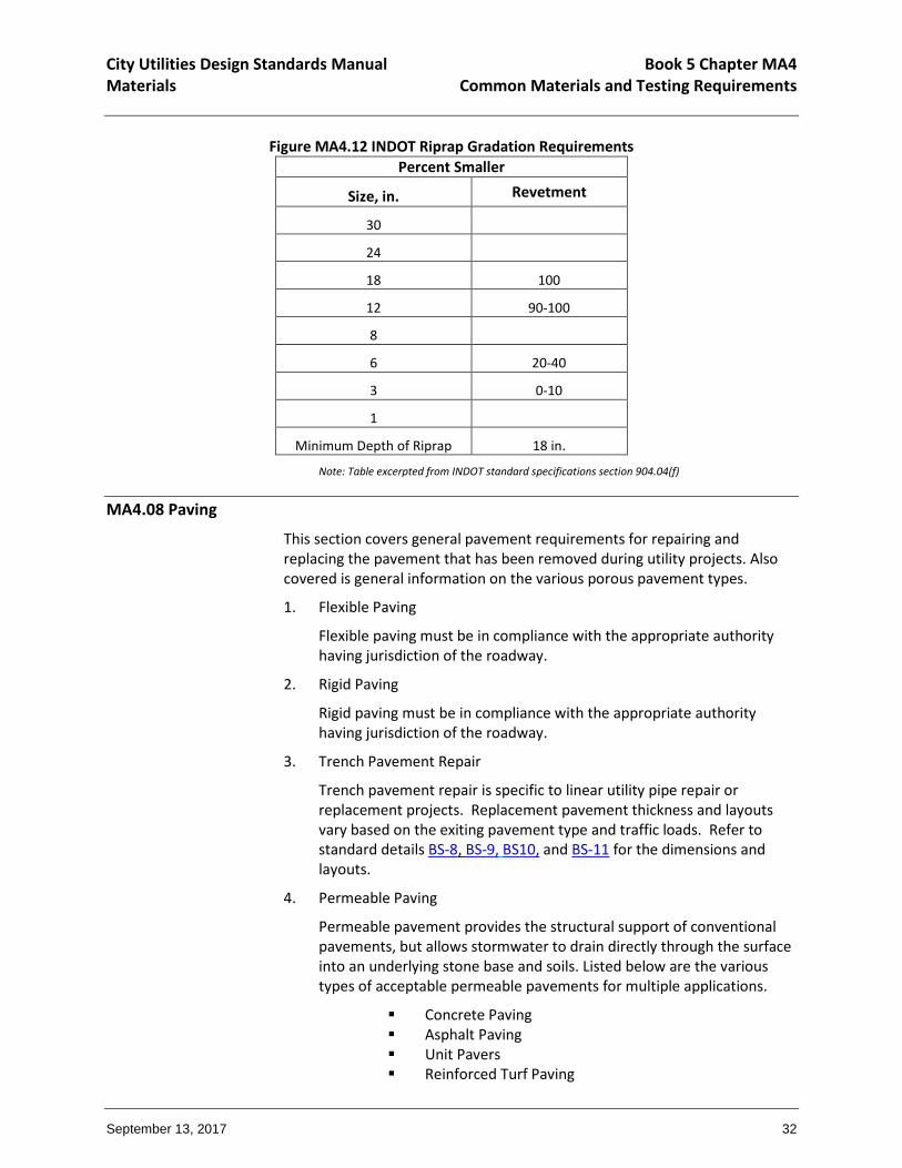
Figure MA4.12 INDOT Riprap Gradation Requirements Percent Smaller
Size, in. Revetment
30
24
18 100
12 90-100
8
6 20-40
3 0-10
1
Minimum Depth of Riprap 18 in.
Note: Table excerpted from INDOT standard specifications section 904.04(f)
MA4.08 Paving
This section covers general pavement requirements for repairing and replacing the pavement that has been removed during utility projects. Also covered is general information on the various porous pavement types.
1. Flexible Paving
Flexible paving must be in compliance with the appropriate authority having jurisdiction of the roadway.
2. Rigid Paving
Rigid paving must be in compliance with the appropriate authority having jurisdiction of the roadway.
3. Trench Pavement Repair
Trench pavement repair is specific to linear utility pipe repair or replacement projects. Replacement pavement thickness and layouts vary based on the exiting pavement type and traffic loads. Refer to standard details BS-8, BS-9, BS10, and BS-11 for the dimensions and layouts.
4. Permeable Paving
Permeable pavement provides the structural support of conventional pavements, but allows stormwater to drain directly through the surface into an underlying stone base and soils. Listed below are the various types of acceptable permeable pavements for multiple applications.
Concrete Paving Asphalt Paving Unit Pavers Reinforced Turf Paving
City Utilities Design Standards Manual Book 5 Chapter MA4 Materials Common Materials and Testing Requirements
September 13, 2017 33
Design guidance for permeable pavements can be found in Section 4.0 of the Green Infrastructure Design Manual located here: https://www.cityoffortwayne.org/utilities/169-design-and-construction/3242-green-design-standards.html
Unit pavers and reinforced turf paving are typically proprietary products. Coordinate with manufactures for acceptable applications and design.
5. Curb, Gutters, Sidewalks, Ramps, and Driveways
Acceptable curb, gutter, sidewalk, ramp and driveway requirements must be in compliance with applicable requirements of governing authorities having jurisdiction.
MA4.09 Lawns and Grasses
This section contains requirements for seeding, soil supplements, planting accessories, sodding, and topsoil.
1. Topsoil
Use fertile, friable, natural topsoil, surface soil, capable of sustaining vigorous plant growth; free of any admixture of subsoil, clods of hard earth, plants or roots, sticks, stones larger than ½-inch in diameter, or other extraneous material harmful to plant growth, in compliance with ASTM D5268.
Reuse of surface soil stockpiled on-site is acceptable. Verify suitability of stockpiled surface soil to produce topsoil, as specified. If not suitable, amend topsoil to meet requirements. Clean surface soil of roots, plants, sod, stones, clay lumps, and other extraneous materials harmful to plant growth.
Topsoil layer shall be placed at a minimum thickness of 2-inches.
2. Grass Seed
Lawn Grass Seed Mixture: Provide fresh, clean, new-crop seed complying with the tolerance for purity and germination established by the supplier. Provide seed of the grass species, proportions and minimum percentages of purity, germination, and maximum percentage of weed seed as listed below.
A. Lawn Grass Seed
50 % Premium Grade Kentucky Bluegrass (2 types) 50% perennial ryegrass (2 types)
City Utilities Design Standards Manual Book 5 Chapter MA4 Materials Common Materials and Testing Requirements
September 13, 2017 34
B. No Mow Grass Seed
50% Fawn Tall Fescue (containing no Endophytes). 25% Annual Ryegrass. 25 % Perennial Ryegrass.
3. Turf Grass Sod
Sod shall be a variety or blend of Kentucky Bluegrass or fescue cut to a height of 2 to 3-inches, and shall be free from all primary and noxious weeds.
Use strongly rooted machine-cut sod, not less than 2 years old of uniform density, color and texture from a similar climate region. Sod shall be capable of vigorous growth and development when planted (viable, not dormant) and in strips of no less than 16-inches wide and shall be no less than 2-feet in length. Edges of sod shall be cut to a uniform thickness of no less than ¾-inch (excluding top growth and thatch).
4. Fertilizers
Provide commercial grade complete fertilizer of neutral character, consisting of fast and slow release nitrogen with an analysis of 12-12-12.
5. Mulches
Where seeded lawns are subject to wind or water erosion use an appropriate mulch to protect the grass seed. Provide air-dry, clean, mildew- and certified seed- free, straw mulch.
If applicable, to prevent hydroseeded areas from wind and water erosion during establishment use one of the following:
• Fiber Mulch - Biodegradable, dyed-wood, cellulose-fiber mulch; nontoxic; free of plant-growth or germination inhibitors; with maximum moisture content of 15 percent and a pH range of 4.5 to 6.5.
• Nonasphaltic tackifier - Colloidal tackifier shall be recommended by fiber-mulch manufactures for slurry applications; nontoxic and free of plant growth or germination inhibitors.
6. Water
Provide water acceptable for lawn and grass application, containing no material harmful to plant growth and establishment. Water shall be free from oil, acids, alkalis, and salts.
7. Hydraulic Growth Medium
When the project site contains locations that have locations that are difficult to establish growth, require a hydraulic growth medium. Typical locations are where channelized flow is expected or steep slopes. As required, provide Biotic Earth Black, or similar as produced by Verdyol.
Apply using a hydroseeder and at an application rate of 3,500 lbs per acre. Add seed or other amendments to the slurry prior to application.
City Utilities Design Standards Manual Book 5 Chapter MA4 Materials Common Materials and Testing Requirements
September 13, 2017 35
MA4.10 Utility Pipe Jacking
1. Quality Assurance
Perform Work in accordance with applicable permitting entities that apply, the National Utility Contractors Associations (NUCA) Trenchless Excavation Construction Equipment & Methods Manual, NUCA Pipe Jacking & Microtunneling Design Guide, American Railway Engineering and Maintenance-of-Way Association. (AREMA), and associated guidelines.
When boring, jacking, or tunneling under the applicable permitting entity’s property, make application for and obtain occupancy permit as required in the applicable permitting entity’s Specifications and requirements.
2. Casing and Jacking Pipe Materials
Casing and jacking pipe materials are in accordance with the specifications and requirements of the applicable permitting entity.
3. Carrier Pipe Materials
Carrier pipe materials vary based on the application. Acceptable carrier pipe materials are listed in Chapter MA5 – Stormwater Materials and Testing Requirements, Chapter MA6 – Sanitary Sewer Materials and Testing Requirements and Chapter MA7 - Water Materials and Testing Requirements .
4. Cover Materials
Soil Backfill for Trench Approaches and Pits to Finish Grade: Subsoil with no rocks over 6-inches in diameter, frozen earth or foreign matter.
5. Casing End Seals
Brick and Mortar Grout Mix: One part Portland cement, and 6 parts mortar sand mixed with water to consistency applicable for brick and mortar grouting.
• Mortar Sand: ASTM C33 • Portland Cement: ASTM C150 • Carrier Pipe Padding: 15 pound Building Felt
6. Casing Spacers
Acceptable casing spacers include:
• CCS Series by Cascade Waterworks Manufacturing • Or approved equal
7. Steel Strapping
Use steel strapping in accordance with ASTM A36/A36M.