City Research Onlineopenaccess.city.ac.uk/18528/1/Paper_AG_FP_20_02_2017_Final_.pdf-excited tall...
7
City, University of London Institutional Repository Citation: Giaralis, A. & Petrini, F. (2017). Optimum design of the tuned mass-damper- inerter for serviceability limit state performance in wind-excited tall buildings. Procedia Engineering, 199, pp. 1773-1778. doi: 10.1016/j.proeng.2017.09.453 This is the published version of the paper. This version of the publication may differ from the final published version. Permanent repository link: http://openaccess.city.ac.uk/18528/ Link to published version: http://dx.doi.org/10.1016/j.proeng.2017.09.453 Copyright and reuse: City Research Online aims to make research outputs of City, University of London available to a wider audience. Copyright and Moral Rights remain with the author(s) and/or copyright holders. URLs from City Research Online may be freely distributed and linked to. City Research Online: http://openaccess.city.ac.uk/ [email protected] City Research Online
Transcript of City Research Onlineopenaccess.city.ac.uk/18528/1/Paper_AG_FP_20_02_2017_Final_.pdf-excited tall...

City, University of London Institutional Repository
Citation: Giaralis, A. & Petrini, F. (2017). Optimum design of the tuned mass-damper-inerter for serviceability limit state performance in wind-excited tall buildings. Procedia Engineering, 199, pp. 1773-1778. doi: 10.1016/j.proeng.2017.09.453
This is the published version of the paper.
This version of the publication may differ from the final published version.
Permanent repository link: http://openaccess.city.ac.uk/18528/
Link to published version: http://dx.doi.org/10.1016/j.proeng.2017.09.453
Copyright and reuse: City Research Online aims to make research outputs of City, University of London available to a wider audience. Copyright and Moral Rights remain with the author(s) and/or copyright holders. URLs from City Research Online may be freely distributed and linked to.
City Research Online: http://openaccess.city.ac.uk/ [email protected]
City Research Online

1877-Peer-review under responsibility of
Optimum design of the tuned mass
Abstract
Optimally designed tuned masswindclassical tunedachieving massconsidered,through a nonThe searchconstruction © 201Peer-
Keywords:
1. Introduction
Performanceattention from
* Corresponding author. Tel.:
E-
-7058 © 2017 The Authors. Published by Elsevier review under responsibility of
X International Conference on Structural Dynamics, EURODYN 2017
ptimum design of the tuned masslimit state performance
aDepartment of Civil Engineering, City University of London, bDepartment of Structural and Geotechnical
Abstract
ptimally designed tuned masswind-excited tall buildings subject to vortex shedding effects in a performanceclassical tuned-massachieving mass-amplification and higherconsidered, where TMDIthrough a non-diagonal power spectral density matrix supporting computationally efficient frequency domain structural analyseThe TMDI is optimally designed for search, for a range of construction in the design of new code
2017 The Authors. Published by Elsevier -review under responsibility of
Keywords: Tuned mass damper, inerter, wind, tall buildings,
Introduction
Performance-Based Engineering (PBE) is aattention from researchers and practitioners
* Corresponding author. Tel.: E-mail address: [email protected]
Available online at
The Authors. Published by Elsevier review under responsibility of the organizing committee of EURODYN 2017
X International Conference on Structural Dynamics, EURODYN 2017
ptimum design of the tuned masslimit state performance
Department of Civil Engineering, City University of London, Department of Structural and Geotechnical
ptimally designed tuned mass-damperexcited tall buildings subject to vortex shedding effects in a performance
mass-damper (TMD) with an inerter, a twoamplification and higher
where TMDI is added to the structural system assuming ideal linear inerter behavior. The wind action diagonal power spectral density matrix supporting computationally efficient frequency domain structural analyse
is optimally designed for , for a range of pre-specified attached
in the design of new code
The Authors. Published by Elsevier review under responsibility of
Tuned mass damper, inerter, wind, tall buildings,
Based Engineering (PBE) is aresearchers and practitioners
* Corresponding author. Tel.: [email protected]
Available online at
ScienceDirect
Procedia Engineering
The Authors. Published by Elsevier the organizing committee of EURODYN 2017
X International Conference on Structural Dynamics, EURODYN 2017
ptimum design of the tuned masslimit state performance
Agathoklis Giaralis
Department of Civil Engineering, City University of London, Department of Structural and Geotechnical Engineering,
damper-inerters (TMDIs) are considered to meet codeexcited tall buildings subject to vortex shedding effects in a performance
damper (TMD) with an inerter, a twoamplification and higher-modes
added to the structural system assuming ideal linear inerter behavior. The wind action diagonal power spectral density matrix supporting computationally efficient frequency domain structural analyse
is optimally designed for stiffness, damping, and inertespecified attached TMDI
in the design of new code-compliant tall buildings against wind
The Authors. Published by Elsevier Ltd. review under responsibility of the organizing committee of EURODYN 2017
Tuned mass damper, inerter, wind, tall buildings,
Based Engineering (PBE) is aresearchers and practitioners
3331909346 [email protected]
Available online at www.sciencedirect.com
ScienceDirect
Procedia Engineering 00 (201
The Authors. Published by Elsevier Ltd. the organizing committee of EURODYN 2017
X International Conference on Structural Dynamics, EURODYN 2017
ptimum design of the tuned masslimit state performance in wind
Agathoklis Giaralisa
Department of Civil Engineering, City University of London, Engineering, Sapienza
inerters (TMDIs) are considered to meet codeexcited tall buildings subject to vortex shedding effects in a performance
damper (TMD) with an inerter, a two-terminal device resisting the relative acceleration of its terminals, -damping effects compared to the TMD.
added to the structural system assuming ideal linear inerter behavior. The wind action diagonal power spectral density matrix supporting computationally efficient frequency domain structural analyse
stiffness, damping, and inerteTMDI mass values
compliant tall buildings against wind
nizing committee of EURODYN 2017
Tuned mass damper, inerter, wind, tall buildings, serviceability, passive v
Based Engineering (PBE) is an integrated frameworkresearchers and practitioners aiming to optimally
www.sciencedirect.com
ScienceDirect
17) 000–000
the organizing committee of EURODYN 2017.
X International Conference on Structural Dynamics, EURODYN 2017
ptimum design of the tuned mass-damperin wind-excited tall buildings
a, Francesco Petrini
Department of Civil Engineering, City University of London, Northampton Square, London EC1V 0HBSapienza University of
inerters (TMDIs) are considered to meet codeexcited tall buildings subject to vortex shedding effects in a performance
terminal device resisting the relative acceleration of its terminals, damping effects compared to the TMD.
added to the structural system assuming ideal linear inerter behavior. The wind action diagonal power spectral density matrix supporting computationally efficient frequency domain structural analyse
stiffness, damping, and inerter constant parametersvalues. It is shown
compliant tall buildings against wind.
nizing committee of EURODYN 2017
serviceability, passive vibration control
n integrated frameworkoptimally design stru
www.sciencedirect.com
X International Conference on Structural Dynamics, EURODYN 2017
damper-inerter for serviceabilityexcited tall buildings
, Francesco Petrinib*
Northampton Square, London EC1V 0HBUniversity of Roma, via Eudossiana 18
inerters (TMDIs) are considered to meet code-prescribed serviceability criteria in typical excited tall buildings subject to vortex shedding effects in a performance-based design context. The T
terminal device resisting the relative acceleration of its terminals, damping effects compared to the TMD. A
added to the structural system assuming ideal linear inerter behavior. The wind action diagonal power spectral density matrix supporting computationally efficient frequency domain structural analyse
r constant parameters via a standard numerical optimization shown that the TMDI
nizing committee of EURODYN 2017.
ibration control
n integrated framework that during last design structures achieving
www.elsevier.com/locate/procedia
X International Conference on Structural Dynamics, EURODYN 2017
inerter for serviceabilityexcited tall buildings
*
Northampton Square, London EC1V 0HB, UKvia Eudossiana 18, Rome
prescribed serviceability criteria in typical based design context. The T
terminal device resisting the relative acceleration of its terminals, A benchmark 74
added to the structural system assuming ideal linear inerter behavior. The wind action diagonal power spectral density matrix supporting computationally efficient frequency domain structural analyse
via a standard numerical optimization that the TMDI achieves
during last decade received significantachieving pre-
www.elsevier.com/locate/procedia
X International Conference on Structural Dynamics, EURODYN 2017
inerter for serviceabilityexcited tall buildings
, UK Rome 00184, Italy
prescribed serviceability criteria in typical based design context. The TMDI, couples the
terminal device resisting the relative acceleration of its terminals, benchmark 74-storey buildin
added to the structural system assuming ideal linear inerter behavior. The wind action is defined diagonal power spectral density matrix supporting computationally efficient frequency domain structural analyse
via a standard numerical optimization achieves more lightweight
received significant-specified levels of
www.elsevier.com/locate/procedia
inerter for serviceability
prescribed serviceability criteria in typical MDI, couples the
terminal device resisting the relative acceleration of its terminals, storey building is
is defined diagonal power spectral density matrix supporting computationally efficient frequency domain structural analyses.
via a standard numerical optimization more lightweight
received significant specified levels of

2 Giaralis and Petrini / Procedia Engineering 00 (2017) 000–000
structural performance under different hazards [1]. In this context, PBE has been considered to treat the serviceability performance of tall buildings under wind excitation [2]. In particular, wind-excited slender high-rise buildings with rectangular floor plan are prone to excessive accelerations in the across-wind direction (i.e., within the normal plane to the wind direction) due to vortex shedding effects generated around their edges [3,4]. Ensuring that the across-wind floor accelerations remain below a certain threshold associated with users’ comfort becomes a critical performance requirement for serviceability [5]. In general, increasing the stiffness of the building does not lead to suppression of wind-induced peak accelerations [6]. Consequently, supplemental damping systems are often provided to modern tall buildings appropriately designed to meet the occupants’ comfort requirements prescribed by building codes and guideline. To this aim, tuned mass-dampers (TMDs), among other devices and configurations for supplemental damping, have been widely used over the past three decades for vibration mitigation in wind-excited tall buildings [7,8]. In its simplest form, the linear passive TMD comprises a mass attached towards the top of the building whose oscillatory motion is to be controlled (primary structure) via linear stiffeners, in conjunction with linear energy dissipation devices (dampers). The effectiveness of the TMD relies on “tuning” its stiffness and damping properties for a given primary structure and attached mass, such that significant kinetic energy is transferred from the dynamically excited primary structure to the TMD mass and eventually dissipated through the dampers.
The two main drawbacks of the TMD regarding the suppression of lateral wind-induced floor accelerations are: • The TMD is commonly placed at the upper floors of the building and tuned to control the fundamental lateral
mode shape of the primary structure (e.g. [9]). Nevertheless, peak floor accelerations are heavily influenced by higher modes of vibrations which the TMD cannot control.
• The effectiveness of the TMD for vibration control depends heavily on the attached mass [8,10]. The latter can rarely exceed 0.5% to 1% of the total building mass in tall buildings as it becomes overly expensive to accommodate its weight and volume due to structural and architectural limitations, respectively. To address the above issues and concerns in an innovative manner, Giaralis and Petrini [11] explored the potential
of incorporating an inerter device to wind-excited TMD-equipped tall buildings, to achieve enhanced floor accelerations suppression in the across-wind direction without increasing the attached TMD mass. The inerter is a line-like two-terminal device introduced by Smith in 2002 [12], having negligible mass/weight resisting relative accelerations between its terminals, and characterized by a scalar variable called “inertance”. In [11] the tuned mass-damper-inerter (TMDI) configuration, originally introduced by Marian and Giaralis [13,14] for earthquake engineering applications, was considered. Appreciable gains in reducing peak top floor accelerations in a 74-floor benchmark tall building were achieved compared to the TMD through a parametric study considering non-optimal TMDI stiffness and damping coefficients for fixed attached mass and increasing inertance. These gains are attributed partly to the mass-amplification effect and partly to higher-modes-damping effect endowed to the TMD by the inerter. In the present paper, the same building benchmark structure is used as in [11] to derive optimal TMDI stiffness and damping improving further the TMDI efficiency for floor acceleration control compared to same-attached-mass TMDs.
2. The Tuned Mass-Damper-Inerter (TMDI) for multi-storey building
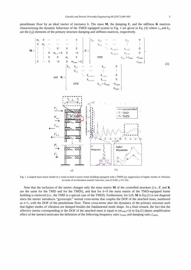
Conceptually defined by Smith (2002) [12], the ideal inerter is a linear massless two-terminal mechanical element resisting the relative acceleration at its terminals through the so-called inertance coefficient, b, measured in mass units. In this regard, the inerter element force F shown schematically as a hatched box in the inlet of Fig.1 reads a
1 2( - )F b u u= && && , where, a dot over a symbol signifies differentiation with respect to time. The ideal inerter can be interpreted as an inertial weightless element whose gain depends on b and on the relative acceleration observed by its terminals [15].
The above considerations led to the TMDI configuration in [13,14] where an inerter device is used as a mass amplifier contributing additional inertia to the attached mass of the classical TMD without increasing its weight to enhance the TMD vibration suppression effectiveness. Specifically, consider a planar linear n-storey frame structure modelled as an n-DOF dynamical system with mass mk (k=1,2,…,n) lumped at the k-th floor as shown in Fig.1 (a). Treating the above system as the primary structure, the TMDI configuration comprises a mass mTMDI attached to the top floor via a linear spring of stiffness kTMDI and a linear dashpot of damping coefficient cTMDI, and linked to the
penultimate floor by an ideal inerter of inertance characterizing the dynamic behaviour of are the (
Fig. 1
Note are the same for the TMD and for the TMDI),buildingsinceas n+1, with the DOF of the penultimate floor.that higher modes of vibration effective inertia corresponding to the DOF ofeffect of the inerter)
penultimate floor by an ideal inerter of inertance characterizing the dynamic behaviour of are the (i,j) elements of the primary structure damping and stiffness matrices, respectively.
1 1,1 1,2
0
0 0 0
m
m
= =
M CM M O O
M M
M M
L
1. Lumped-mass linear model of a wind excited n
Note that the inclusare the same for the TMD and for the TMDI),building is retrieved (i.e., the TMD is a special case of the TMDI). Furthermore, for since the inerter introduce
+1, with the DOF of the penultimate floor.that higher modes of vibration effective inertia corresponding to the DOF ofeffect of the inerter)
penultimate floor by an ideal inerter of inertance characterizing the dynamic behaviour of
) elements of the primary structure damping and stiffness matrices, respectively.
1 1,1 1,2
2
1
0 0 0
0 0 0 0
0 0 0
0 0 0
0 0 0
and
n
m
m b
b c
−
= = −
+M C
L L L L L
L L L M L L M M
M M O O
M M
M M
L
mass linear model of a wind excited n
that the inclusion of the inerterare the same for the TMD and for the TMDI),
is retrieved (i.e., the TMD is a special case of the TMDI). Furthermore, for the inerter introduces “gyroscopic” inertia
+1, with the DOF of the penultimate floor.that higher modes of vibration effective inertia corresponding to the DOF ofeffect of the inerter) motivates the definition of the following
Giaralis and Petrini
penultimate floor by an ideal inerter of inertance characterizing the dynamic behaviour of the
) elements of the primary structure damping and stiffness matrices, respectively.
1 1,1 1,2
1,1 1,2
2
0 0 0
0 0 0 0
0 0 0
0 0 0
0 0 0
n
TMDI
m b
m
m b
b c c
k
b c
kk
= = − −
=
+M C
K
L L L L L
L L L M L L M M
M M O O
,2
SYM k k k
mass linear model of a wind excited n-storeyin terms of acceleration transfer function
ion of the inerter changes onlyare the same for the TMD and for the TMDI),
is retrieved (i.e., the TMD is a special case of the TMDI). Furthermore, for s “gyroscopic” inertia
+1, with the DOF of the penultimate floor.that higher modes of vibration are damped besides the effective inertia corresponding to the DOF of
motivates the definition of the following
Giaralis and Petrini/ Procedia Engineering
penultimate floor by an ideal inerter of inertance b. The mass the TMDI equipped system in Fig. 1 a
) elements of the primary structure damping and stiffness matrices, respectively.
1 1,1 1,2
1,1 1,2
0 0 0
0 0 0 0, ,
0 0 0
0 0 0
TMDIm b
c c c
b c c
b c
= = − +
M C
L L L L L
L L L M L L M M
M M O O
L L
,2
2, 1 2,
1, 1 1,
n n n n
n n n n
k k
k k
SYM k k k
− − −
− − −
L L M M
O
storey frame building equipped with a in terms of acceleration transfer function
changes only the mass matrixare the same for the TMD and for the TMDI), and that
is retrieved (i.e., the TMD is a special case of the TMDI). Furthermore, for s “gyroscopic” inertial cross-terms
+1, with the DOF of the penultimate floor. These crossare damped besides the fundamental mode
effective inertia corresponding to the DOF of the attached mass is equal to (motivates the definition of the following
Procedia Engineering 00 (
The mass M, the damping TMDI equipped system in Fig. 1 a
) elements of the primary structure damping and stiffness matrices, respectively.
2,2
1 1,1 1,2
1,
0 0 0
0 0 0 0, ,
0 0 0
n
c c c
c
c c
b c c
SYM c c
b c
k
L L L L L
L L L M L L M M
M M O O
L L
2, 1 2,
1, 1 1,
,
n n n n
n n n n
n n TMDI TMDI
k k
k k
SYM k k k
− − −
− − −
+ −
L L M M
frame building equipped with a in terms of acceleration transfer function, case β=0.69,
the mass matrixand that for b=0 the
is retrieved (i.e., the TMD is a special case of the TMDI). Furthermore, for terms that couples thecross-terms alter fundamental mode
the attached mass is equal to (motivates the definition of the following frequency ratio
00 (2017) 000–000
, the damping CTMDI equipped system in Fig. 1 are given in Eq. (
) elements of the primary structure damping and stiffness matrices, respectively.
1,
2, 1 2,
1, 1 1,
,
0 0 0
0 0 0 0, ,
0 0 0
0
n
n n n n
n n n n
n n TMDI TMDI
c c c
c c
b c c
SYM c c
b c
c
− − −
− − −
+ −
L L L L L
L L L M L L M M
0
0
n n TMDI TMDI
TMDI
SYM k k k
k
+ −
L L M M
frame building equipped with a TMDI (a); suppression of higher modes of vibration=0.69, μ=0.1 (b)
M of the controlled structure (i.e., the mass matrix of
is retrieved (i.e., the TMD is a special case of the TMDI). Furthermore, for bthat couples the DOF of the attached mass, numbered
alter the dynamics of the primary structure fundamental mode shape. As a final remark, the fact that the
the attached mass is equal to (mTMDI+bfrequency ratio υTMDI and damping ratio
000
C, and the stiffness re given in Eq. (1
) elements of the primary structure damping and stiffness matrices, respectively.
1 2,
1, 1 1,
0 0 0
0 0 0 0, ,
0 0 0
n
n n n n
n n n n
n n TMDI TMDI
TMDI
SYM c c
b c
c
− − −
− − −
+ −
L L L M L L M M
suppression of higher modes of vibration
of the controlled structure (i.e., mass matrix of the TMD
b≠0, M in Eq.(1) iDOF of the attached mass, numbered
the dynamics of the primary structure As a final remark, the fact that the
b) in Eq.(1) (mass amplification and damping ratio
, and the stiffness K matrices 1) where ci,j and
, ,
suppression of higher modes of vibration
of the controlled structure (i.e., C and the TMD-equipped frame
in Eq.(1) is not diagonalDOF of the attached mass, numbered
the dynamics of the primary structure As a final remark, the fact that the
(mass amplification and damping ratio ξTMDI.
3
matrices and ki,j
(1)
suppression of higher modes of vibration
and K frame
diagonal DOF of the attached mass, numbered
the dynamics of the primary structure such As a final remark, the fact that the
(mass amplification

4 Giaralis and Petrini / Procedia Engineering 00 (2017) 000–000
1
( ),
2 ( )
TMDI
TMDI TMDITMDI TMDI
TMDI TMDI
k
m b c
m b kυ ξω
+= =
+, (2)
to characterize the dynamics of the TMDI given an attached mass mTDMI and inertance b.
3. Adopted primary structure and wind excitation model
To optimize the TMDI in Fig. 1(a) for suppressing wind induced oscillations in tall buildings, a high-rise building previously considered for the development of a performance-based wind engineering framework [4] is taken as a benchmark structure. The adopted structure is a 74-storey steel frame building of 305m total height with a 50m-by-50m footprint. The building comprises two spatial steel frames, one inner including 12 columns, and one outer formed by 28 columns, the two frames are connected by three outriggers located at 100m, 200m, and 300m in elevation. All columns have hollow square sections, with varying outer dimensions and thickness along the building height ranging in between 1.20m to 0.50m, and 0.06m to 0.025m, respectively. Beams are of various standard double-T steel section profiles and all beam-to-column joints are taken as rigid. The outriggers are braces consisted of double-T beams and hollow-square diagonal struts. The first three natural frequencies of these modes and the corresponding modal participating mass ratios in parentheses are 0.185Hz (0.6233), 0.563Hz (0.1900), and 1.052Hz (0.0745). The modal damping ratios ξs has been assumed equal to 2% for the first 9 modes [11]. Starting from detailed FE model of the structure, a reduced dynamic system with n=74 DOFs is derived in terms of mass, damping and stiffness matrices to serve as the primary (uncontrolled) structure. The 74 DOFs of the system correspond to the lateral translational DOFs of the FE model. The wind action is considered only in the across-wind direction as this is the critical direction to check for the occupants’ comfort criterion for this particular structure [4]. The wind force components Fk (k=1,2,…,74) acting at the slab heights of the primary structure as pictorially shown in Fig.1 are modelled as a zero-mean Gaussian ergodic spatially correlated random field represented in the frequency domain by a ( ) 74 74ω ×∈74
FFS � PSD matrix. The response displacement and acceleration PSD matrices of the TMDI-equipped primary structure are obtained
using the frequency domain input-output relationships
( ) ( ) ( ) ( ) ( ) ( )* 4andω ω ω ω ω ω ω= =&&&&xx FF xx xxS B S B S S (3)
respectively. In Eq. (3), SFF is the PSD wind force matrix 74FFS augmented by a zero row and a zero column
corresponding to the DOF of the TMDI which is not subjected to any wind load and the “*” superscript denotes complex matrix conjugation, and the transfer matrix B is given as ( ) 12 iω ω ω
− = − + B K M C , being 1i = − . Finally, peak k-th floor accelerations are estimated by the expression { } 2peak
kk xx g σ=&&
&& , and the peak factor g is estimated by the widely used empirical formula ( ) ( )2 0.577 2wind windg ln T ln Tη η= + .
4. Performance-Based optimization of the TMDI
The performance of the building in term of occupants comfort are evaluated by comparing the hourly peak accelerations of the floors as experimented under a design wind having an annual return period (mean wind velocity Vref=35 m/s at the top of the building at the considered site), with code-prescribed threshold values depending on the first natural frequency of the building in the across-wind direction.
Then, considering the configuration in Fig. 1(a), optimization of the TMDI parameters (Design Variables - DVs) υTMDI and ξTMDI in Eq. (2) is conducted for fixed values of the TMD mass ratio μ= mTMDI/Mbuilding and inertance ratio β=b/Mbuilding by using the pattern search algorithm [16]. Since the maximum peak acceleration is always attained by the top floor of the building, the goal of the optimization problem is to minimize the hourly peak top floor acceleration { }74peak x&& induced by the considered wind loads, subjected to the constrains of meeting the structural performances in terms of peak top floor accelerations ( { }74peak thresholdx x≤&& && for building occupant comfort) and maximum peak drift along the height of the building ( { }1 74 1max peakj j j thresholdx x θ≤ ≤ −
− ≤ structural and non-structural

damage limitation)threshold values considered for the constrains and the
The resulting values of the
configurations in terms of force, obtained by multiplying the inertance shown in Fig. 2(d). It is seen that this force takes on reasonable values that can well be accommodated by thestructure.
Infigures 2(a) and 2(b) with the obtained values of the respectnumbers.
where examined case.shapesshown to be
damage limitation)threshold values considered for the constrains and the
The resulting values of the configurations in terms of force, obtained by multiplying the inertance shown in Fig. 2(d). It is seen that this force takes on reasonable values that can well be accommodated by thestructure.
Fig. 2. Results of the TMDI optimization in at fixed values of
In order to express the optimal values offigures 2(a) and 2(b) with the obtained values of the respect to β and/numbers. At the end of the
26 288 1 11
84 84 84 65TMDI TMDI sυ µ β β ξ µ β β β ξ = − − + = − + + +
where ξs1 is the modal damping ratio of the first structural examined case. The matching betweenshapes) and the values fromshown to be satisfactory
damage limitation). The details of the strthreshold values considered for the constrains and the
Table 1. Parameters’ values in the TMDI optimization
Design variableυTMDI ξTMDI
Fixed parametersμ β
The resulting values of the configurations in terms of peakforce, obtained by multiplying the inertance shown in Fig. 2(d). It is seen that this force takes on reasonable values that can well be accommodated by the
Results of the TMDI optimization in at fixed values of performances of the optimal configurations ; (d)
order to express the optimal values offigures 2(a) and 2(b) with μ, i.e. the obtained values of the ai and
and/or β . Finally, the At the end of the fitting
26 288 1 11
84 84 84 65TMDI TMDI sυ µ β β ξ µ β β β ξ = − − + = − + + +
is the modal damping ratio of the first structural The matching betweenvalues from Eq. (6) (dashed lines) are shown in
satisfactory, with a maximum error
Giaralis and Petrini
The details of the structural optimization problem are threshold values considered for the constrains and the
Parameters’ values in the TMDI optimization
Design variables min0.210
Fixed parameters values01%
0-
The resulting values of the optimization are shown in
{ }74peak x&& are also force, obtained by multiplying the inertance shown in Fig. 2(d). It is seen that this force takes on reasonable values that can well be accommodated by the
Results of the TMDI optimization in at fixed values of performances of the optimal configurations ; (d)
order to express the optimal values of, i.e. υTMDI=a1µ+c
and ci (i=1,2) parameters areinally, the obtained fitting process, the optimal values
26 288 1 111 , 11 1
84 84 84 65TMDI TMDI sυ µ β β ξ µ β β β ξ= − − + = − + + +
is the modal damping ratio of the first structural The matching between the numerical values obta
Eq. (6) (dashed lines) are shown inwith a maximum error
Giaralis and Petrini/ Procedia Engineering
uctural optimization problem are threshold values considered for the constrains and the value ranges
Parameters’ values in the TMDI optimization
min Max0.2 1.2 10-5 0.8
values 01%-0.9%
-0.4
optimization are shown in also compared to
force, obtained by multiplying the inertance b by the peak relative acceleration between the two inerter terminals, is shown in Fig. 2(d). It is seen that this force takes on reasonable values that can well be accommodated by the
Results of the TMDI optimization in at fixed values of μ and performances of the optimal configurations ; (d)
order to express the optimal values of υTMDI and ξ+c1 and ξTMDI =aparameters are
obtained polynomial he optimal values
(26 288 1 111 , 11 1
84 84 84 65TMDI TMDI sυ µ β β ξ µ β β β ξ= − − + = − + + +
is the modal damping ratio of the first structural the numerical values obta
Eq. (6) (dashed lines) are shown inwith a maximum error (absolute
Procedia Engineering 00 (
uctural optimization problem are value ranges considered for the DVs
Parameters’ values in the TMDI optimization
Max Note: the objective is to minimize the peak
floor acceleration at the top of the building
Threshold response
thresholdx&&
thresholdθ
optimization are shown in Figure 2, where the performance the classical TMD (
by the peak relative acceleration between the two inerter terminals, is shown in Fig. 2(d). It is seen that this force takes on reasonable values that can well be accommodated by the
and β : (a) optimal υperformances of the optimal configurations ; (d) peak inerter force for the optimal configurations
ξTMDI in closed form=a2µ+c2 is first undertaken
parameters are fitted with polynomial polynomial coefficients
he optimal values are written
) 1
26 288 1 111 , 11 1
84 84 84 65TMDI TMDI sυ µ β β ξ µ β β β ξ= − − + = − + + +
is the modal damping ratio of the first structural mode of the primary structure equal to the numerical values obtained by the optimization algorithm (
Eq. (6) (dashed lines) are shown in Figure 3(absolute difference between the true
00 (2017) 000–000
uctural optimization problem are summarizedconsidered for the DVs
Note: the objective is to minimize the peak
floor acceleration at the top of the buildingThreshold response value
igure 2, where the performancethe classical TMD (case β
by the peak relative acceleration between the two inerter terminals, is shown in Fig. 2(d). It is seen that this force takes on reasonable values that can well be accommodated by the
υTMDI values; (b) optimal peak inerter force for the optimal configurations
in closed form, a linear regression of the values in is first undertaken
polynomial linear coefficients are expressed by are written as
1TMDI TMDI sυ µ β β ξ µ β β β ξ= − − + = − + + +
mode of the primary structure equal to ined by the optimization algorithm (Figure 3, where the agreement
difference between the true
000
summarized in Table 1, considered for the DVs.
Note: the objective is to minimize the peak top floor acceleration at the top of the building
value 102.9 mm/s2
0.004
igure 2, where the performance β=0). Moreover, the peak inerter
by the peak relative acceleration between the two inerter terminals, is shown in Fig. 2(d). It is seen that this force takes on reasonable values that can well be accommodated by the
optimal ξTMDI valuespeak inerter force for the optimal configurations
a linear regression of the values in is first undertaken for different
linear and/or quadratic expressed by fractions of two integer
mode of the primary structure equal to ined by the optimization algorithm (
, where the agreement between the two difference between the true and the fitted
in Table 1, showing
top floor acceleration at the top of the building
of the optimized Moreover, the peak inerter
by the peak relative acceleration between the two inerter terminals, is shown in Fig. 2(d). It is seen that this force takes on reasonable values that can well be accommodated by the
values; (c) structural
a linear regression of the values in values of β. Next
or quadratic lawsfractions of two integer
mode of the primary structure equal to 2% in the ined by the optimization algorithm (dots of various
between the two fitted values divided
5
showing the
of the optimized Moreover, the peak inerter
by the peak relative acceleration between the two inerter terminals, is shown in Fig. 2(d). It is seen that this force takes on reasonable values that can well be accommodated by the
structural
a linear regression of the values in . Next,
with fractions of two integer
(6)
in the dots of various
between the two is values divided

6 Giaralis and Petrini / Procedia Engineering 00 (2017) 000–000
by the true value) equal to 0.06% for υTMDI, and 7% for ξTMDI, in both cases occurring for the largest considered β value.
Fig. 3. Comparison between fitted (Eq. (6)- dashed lines), and optimum values (β=0.1 (∆), 0.2 (○), 0.3 (x), 0.4 (□)) for υTMDI and ξTMDI
5. Conclusions
Optimal TMDI damping and frequency ratio parameters (ξTMDI and υTMDI respectively) are found to follow the same trend of classical TMD parameters at increasing mass for fixed inertance values. Structural response results (Fig. 2(c)) confirm that for small attached mass the TMDI performs significantly better than the TMD. Peak inerter force is found to be at manageable levels for connecting the inerter terminals with the primary structure. Lastly, closed form expression of υTMDI and ξTMDI parameters as a function of mass and inertance have been derived by means of ordinary polynomial fitting techniques in the range of values that are relevant to tall buildings.
Acknowledgements
This work has been funded by EPSRC in UK, under grant EP/M017621/1.
References
[1] M. Barbato, A. Palmeri, F. Petrini, Special Issue on Performance-based engineering, Editorial foreword, Engineering Structures 78(2014) 1-2. [2] Spence, S.M.J. and Gioffrè, M. (2012). “Large scale reliability-based design optimization of wind excited tall buildings.” Prob. Eng. Mech.,
28, 206-215 [3] Liang, S., Liu, S., Li, Q.S., Zhang, L. and Gu, M. (2002). “Mathematical model of across-wind dynamic loads on rectangular tall buildings.”
Journal of Wind Engineering and Industrial Aerodynamics, 90, 201-251. [4] Petrini, F. and Ciampoli, M. (2012). “Performance-based wind design of tall buildings.” Structure & Infrastructure Engineering - Maintenance,
Management, Life-Cycle Design & Performance, 8(10), 954-966. [5] Kwok, K.C.S, Hitchcock, P.A. and Burton, M.D. (2009). “Perception of vibration and occupant comfort in wind-excited tall buildings.”
Journal of Wind Engineering and Industrial Aerodynamics, 97, 368–380. [6] Tamura, Y., Kawana, S., Nakamura, O., Kanda, J. and Nakata S. (2006). “Evaluation perception of wind-induced vibration in buildings.”
Proceedings of the Institution of Civil Engineers - Structures and Buildings, 159(5), 283-293. [7] Kareem, A., Kijewski, T. and Tamura, Y. (1999). “Mitigation of motions of tall buildings with specific examples of recent applications.”
Wind and Structures, 2(3), 201-251. [8] Tse, K., Kwok, K., and Tamura, Y. (2012). "Performance and Cost Evaluation of a Smart Tuned Mass Damper for Suppressing Wind-Induced
Lateral-Torsional Motion of Tall Structures." J. Struct. Eng., 10.1061/(ASCE)ST.1943-541X.0000486, 514-525. [9] Rana, R. and Soong, T.T. (1998). “Parametric study and simplified design of tuned mass dampers.” Engineering Structures, 20(3), 193-204 [10] De Angelis, M., Perno, S. and Reggio, A. (2012). “Dynamic response and optimal design of structures with large mass ratio TMD.”
Earthquake Eng. Struct. Dyn., 41, 41–60. [11] Giaralis, A. and Petrini, F. “Wind-induced vibration mitigation in tall buildings using the tuned mass-damper-inerter (TMDI)”. Accepted for
pubblication, ASCE J. Struct. Eng., [12] Smith, M.C. (2002). “Synthesis of Mechanical Networks: The Inerter.” IEEE Transactions On Automatic Control, 47(10), 1648-1662 [13] Marian, L. and Giaralis, A. (2013). “Optimal design of inerter devices combined with TMDs for vibration control of buildings exposed to
stochastic seismic excitations.” Proc,.11th ICOSSAR Int. Conf. on Structural Safety and Reliability, CRC Press, NY, 1025-1032. [14] Marian, L. and Giaralis, A. (2014). “Optimal design of a novel tuned mass-damper–inerter (TMDI) passive vibration control configuration
for stochastically support-excited structural systems.” Prob. Eng. Mech., 38, 156–164. [15] Lazar, I.F., Neild, S.A. and Wagg D.J. (2014). “Using an inerter-based device for structural vibration suppression.” Earthquake Eng. Struct.
Dyn., 43(8), 1129-1147. [16] Charles, A. and Dennis Jr., J.E. (2003) "Analysis of Generalized Pattern Searches." SIAM Journal on Optimization. 13(3), 889–903.
0.96
0.97
0.98
0.99
1.00
0 0.002 0.004 0.006 0.008 0.01
υ TM
DI
μ
0.04
0.08
0.12
0.16
0 0.002 0.004 0.006 0.008 0.01
ξ TMD
I
μ