CITY OF TORONTO CONSOLIDATED DATA CENTRE (CTCDC) · 2020-04-29 · CITY OF TORONTO CONSOLIDATED...
197
CITY OF TORONTO CONSOLIDATED DATA CENTRE (CTCDC) Issue K1 - Feasibility Study & Preliminary Facility Design 3301 Markham Road December 13, 2010 VOLUME 1 of 2
Transcript of CITY OF TORONTO CONSOLIDATED DATA CENTRE (CTCDC) · 2020-04-29 · CITY OF TORONTO CONSOLIDATED...
CITY OF TORONTO
CONSOLIDATED DATA CENTRE
(CTCDC)
Issue K1 - Feasibility Study & Preliminary Facility Design 3301 Markham Road
December 13, 2010 VOLUME 1 of 2
CITY OF TORONTO CONSOLIDATED DATA CENTRE (CTCDC) Project 05881.000 Feasibility Study & Preliminary Facility Design ISSUE K1 3301 Markham Road December 13, 2010
PROJECT NO. 05881.000 PAGE 05881-1 ©WZMH R:\5881\ARCHIVE\ISSUE K_MARKHAM REPORT\ISSUE K1\3301 MARKHAM ROAD REPORT_ISSUE K1.DOCX
TABLE OF CONTENTS PREFACE ................................................................................................................................... 4 SECTION A INTRODUCTION ................................................................................................. 6 A.1 BACKGROUND ................................................................................................... 6 A.2 PURPOSE OF THE FACILITY ............................................................................. 6 A.2.1 Services Provided by the Facility ......................................................................... 6 A.2.2 Critical Success Factors.........................................................................................6 A.3 OBJECTIVES OF THE REPORT ......................................................................... 7 A.4 ORGANIZATION OF THE REPORT .................................................................... 7 SECTION B EXECUTIVE OVERVIEW OF THE FACILITY PROGRAM .................................. 9 B.1 INTRODUCTION ................................................................................................. 9 B.1.1 Existing Facilities - Data Collection ...................................................................... 9 B.1.2 Decision Matrix .................................................................................................... 9 B.2 WATTS / S.F. ..................................................................................................... 10 B.3 FUTURE GROWTH ........................................................................................... 10 B.4 NEXT STEPS .................................................................................................... 11 SECTION C BASIS FOR THE DESIGN OF THE FACILITY .................................................. 12 C.1 DATA CENTRE STANDARDS ........................................................................... 12 C.1.1 Data Centre Redundancy Requirements (Conceptual Description) .................... 12 C.1.2 ASHRAE & CSA Standards ............................................................................... 15 C.2 ENERGY EFFICIENCY...................................................................................... 15 C.2.1 LEED Canada .................................................................................................... 16 C.3 OTHER REQUIREMENTS ................................................................................. 20 C.3.1 Building Code Requirements ............................................................................. 20 SECTION D DATA CENTRE REQUIREMENTS .................................................................... 22 D.1 SITE UPGRADES .............................................................................................. 22 D.1.1 Electrical Infrastructure ...................................................................................... 23 D.1.2 IT / Communications Infrastructure .................................................................... 24 D.1.3 Site Security ....................................................................................................... 24 D.1.4 Site Parking & Traffic Analysis ........................................................................... 24 D.2 ARCHITECTURAL REQUIREMENTS ............................................................... 25 D.2.1 Building Statistics ............................................................................................... 25 D.2.2 Building Envelope Requirements ....................................................................... 26
CITY OF TORONTO CONSOLIDATED DATA CENTRE (CTCDC) Project 05881.000 Feasibility Study & Preliminary Facility Design ISSUE K1 3301 Markham Road December 13, 2010
PROJECT NO. 05881.000 PAGE 05881-2 ©WZMH R:\5881\ARCHIVE\ISSUE K_MARKHAM REPORT\ISSUE K1\3301 MARKHAM ROAD REPORT_ISSUE K1.DOCX
D.2.3 Building Interior Requirements ........................................................................... 27 D.3 STRUCTURAL REQUIREMENTS ..................................................................... 30 D.3.1 Introduction ........................................................................................................ 30 D.3.1.1 Project Description ............................................................................................. 30 D.3.1.2 General Criteria and Assumptions ..................................................................... 30 D.3.2 Foundations ....................................................................................................... 31 D.3.3 Slab-on-Grade ................................................................................................... 31 D.3.4 Second Floor Structural System ......................................................................... 32 D.3.5 Roof Structural System ...................................................................................... 32 D.3.6 Diesel Fuel Storage ........................................................................................... 33 D.3.7 Design Analysis ................................................................................................. 33 D.3.8 Material Specifications ....................................................................................... 35 D.4 MECHANICAL REQUIREMENTS ...................................................................... 36 D.4.1 General Requirements ....................................................................................... 36 D.4.2 Site Servicing Requirements .............................................................................. 39 D.4.3 Plumbing and Drainage Systems ....................................................................... 40 D.4.4 Fire Protection Systems ..................................................................................... 43 D.4.5 Heating and Cooling Plant ................................................................................. 44 D.4.6 Heating, Ventilation and Air Conditioning Systems ............................................. 46 D.4.7 Equipment, Systems and Materials .................................................................... 50 D.4.8 Building Automation System .............................................................................. 55 D.4.9 Commissioning .................................................................................................. 59 D.5 ELECTRICAL REQUIREMENTS ....................................................................... 63 D.5.1 Outline Scope of Work ....................................................................................... 63 D.5.2 General Requirements ....................................................................................... 64 D.5.3 Power Service .................................................................................................... 65 D.5.4 27.6KV Main Incoming Power Distribution ......................................................... 65 D.5.5 Liquid Cooled Power Transformers .................................................................... 66 D.5.6 13.8KV UPS Input Power Distribution ................................................................ 66 D.5.7 Diesel Engine Coupled 13.8KV Rotary UPS System .......................................... 67 D.5.8 600V and 208V Electrical Distribution ................................................................ 68 D.5.9 Surge Protection ................................................................................................ 69 D.5.10 Low Voltage Power Distribution ......................................................................... 70 D.5.11 General Power Distribution ................................................................................ 71 D.5.12 Wiring Methods .................................................................................................. 72 D.5.13 Dry Type Transformers ...................................................................................... 72 D.5.14 Life Safety Systems ........................................................................................... 73 D.5.15 Energy Conservation ......................................................................................... 74 D.5.16 Lighting Design .................................................................................................. 75 D.5.17 Power Monitoring and Control System ............................................................... 75 D.5.18 Building Lighting Control System ....................................................................... 76 D.5.19 Lightning Protection System .............................................................................. 76 D.5.20 Telephone and Data Wiring Systems ................................................................. 77 D.5.21 Fire Alarm System ............................................................................................. 77 D.5.22 Security and CCTV Surveillance System ........................................................... 78
CITY OF TORONTO CONSOLIDATED DATA CENTRE (CTCDC) Project 05881.000 Feasibility Study & Preliminary Facility Design ISSUE K1 3301 Markham Road December 13, 2010
PROJECT NO. 05881.000 PAGE 05881-3 ©WZMH R:\5881\ARCHIVE\ISSUE K_MARKHAM REPORT\ISSUE K1\3301 MARKHAM ROAD REPORT_ISSUE K1.DOCX
D.6 IT / COMMUNICATIONS REQUIREMENTS ...................................................... 79 D.6.1 Design Criteria ................................................................................................... 79 D.7 PHYSICAL SECURITY ...................................................................................... 82 SECTION E COST ESTIMATE .............................................................................................. 83 E.1 BACKGROUND ................................................................................................. 83 E.2 ESTIMATE RANGE ........................................................................................... 83 E.3 VALUE ENGINEERING OPTIONS .................................................................... 84 E.4 ESTIMATE ......................................................................................................... 84 E.4.1 How to Read the Estimate ................................................................................. 84 SECTION F CONCLUSIONS .............................................................................................. 85 F.1 CONCLUSIONS................................................................................................. 85 F.1.1 Risks and Challenges ........................................................................................ 85 F.1.2. Project Timelines ............................................................................................... 86 SECTION G TEAM ................................................................................................................ 87 G.1 CONSULTANT TEAM ........................................................................................ 87 G.2 CONTRIBUTORS .............................................................................................. 87 SECTION H BACKGROUND INFORMATION ....................................................................... 88 H.1 PREVIOUS REPORTS & STUDIES................................................................... 88 H.2 COST ESTIMATES ............................................................................................ 88
H.3 SPECIAL ISSUE PACKAGES............................................................................ 89 SECTION J GLOSSARY ....................................................................................................... 92 SECTION K APPENDICES ................................................................................................... 96 K.1 DIAGRAMS, CHARTS, REPORTS .................................................................... 96
CITY OF TORONTO CONSOLIDATED DATA CENTRE (CTCDC) Project 05881.000 Feasibility Study & Preliminary Facility Design ISSUE K1 3301 Markham Road December 13, 2010
PROJECT NO. 05881.000 PAGE 05881-4 ©WZMH R:\5881\ARCHIVE\ISSUE K_MARKHAM REPORT\ISSUE K1\3301 MARKHAM ROAD REPORT_ISSUE K1.DOCX
PREFACE The following report is based on information provided by City of Toronto, the consultant team and industry standards with regards to the design and construction of a new consolidated data centre. The intent of the report is to provide a solution for a new Tier III consolidated data centre facility that can accommodate anticipated growth over a period of the next twenty years. The requirements outlined in this report are in the opinion of the consultant team to represent one of few practical options for a new facility to ensure that the business needs of the City of Toronto are met over the next twenty years. (In addition to the solutions provided for a Tier III facility, a cost estimate and associated commentary has been provided in this report for a Tier II Plus facility. The area requirements for a Tier II Plus facility are the same as those required for a Tier III facility and the mechanical components do not change. There are some electrical shortfalls between the Tier II Plus and Tier III facility that would have to be addressed in more detail should City of Toronto wish to pursue the Tier II Plus option.) Assumptions The technical requirements provided in this report are based on the following assumptions: 1) All construction work is completed by competent contractors experienced in data centre
projects including upgrades to existing facilities in live and operating environments. 2) Servicing (i.e. electrical power, telecommunications and water supply) can accommodate
the requirements set out within this report and or will be upgraded to suit the new design. The technical specifications, drawings and costs for all services to the site are not included in this report.
3) This report deals with the construction of a new building and support for infrastructure
such as the mechanical and electrical systems. This report does not include the technical specifications and costs associated with the telecommunication structured cabling, telecommunication system network and structured cabling distribution equipment, computer equipment outside and within the Raised Floor “White Space” of the data centre.
Cost Issues An estimate has been prepared based on the technical information provided in this report and previous studies completed for City of Toronto by other consultant team members. The estimate provided is the mid-range cost for the project described in this report. A range (from low to high) has been provided due to the fact that the information contained within this report is concept in nature only and must be further developed in the next phases to allow for more accurate pricing. As the information is further developed and detailed, the estimate range will be decreased and the overall cost more clearly defined. As the project progresses into the next phase, the items that can affect the cost range (from low to high) are as follows:
• Final confirmation of building areas
• Detailed design of all mechanical and electrical systems
CITY OF TORONTO CONSOLIDATED DATA CENTRE (CTCDC) Project 05881.000 Feasibility Study & Preliminary Facility Design ISSUE K1 3301 Markham Road December 13, 2010
PROJECT NO. 05881.000 PAGE 05881-5 ©WZMH R:\5881\ARCHIVE\ISSUE K_MARKHAM REPORT\ISSUE K1\3301 MARKHAM ROAD REPORT_ISSUE K1.DOCX
• Detailed design of all structural systems
• High power density IT equipment racks and associated supplementary cooling equipment
• Industry prices
• Level of energy efficient design features (i.e. LEED status)

SECTION A INTRODUCTION
CITY OF TORONTO CONSOLIDATED DATA CENTRE (CTCDC) Project 05881.000 Feasibility Study & Preliminary Facility Design ISSUE K1 3301 Markham Road December 13, 2010
PROJECT NO. 05881.000 PAGE 05881-6 ©WZMH R:\5881\ARCHIVE\ISSUE K_MARKHAM REPORT\ISSUE K1\3301 MARKHAM ROAD REPORT_ISSUE K1.DOCX
SECTION A INTRODUCTION A.1 BACKGROUND This CTCDC Feasibility Study has been requested by City of Toronto to determine the technical requirements, costs and risks associated with the creation of a new Tier III level consolidated data centre facility. The consolidated data centre is to house the City Divisions technology assets and will provide
leased services to the Toronto Transit Commission (TTC) and Toronto District School Board
(TDSB). The building requirements have been determined to allow for the City’s growth over a
20 year period with designs for a Tier III facility, referred to herein as ‘Option 1A’. For cost
comparison purposes, a review is also included for a Tier II Plus scenario, referred to herein as
‘Option 1B’ (whereby a Tier II facility is constructed with capacity to expand to Tier III in the future).
A.2 PURPOSE OF THE FACILITY
The purpose of the proposed facility is to provide highly redundant and secure electronic services for the City Divisions. The intent of this report is to provide a solution that will allow the City to expand its current capacity and upgrade its redundancy and security in a consolidated environment. A.2.1 Services Provided by the Facility The services to be provided by the new facility are as follows:
• Capacity to store data and highly sensitive electronic information relating to the day-to-day business needs of the City. The storage of all data and electronic information must be accessible 24 hours per day, 7 days per week, 365 days per year = 24/7/365 - forever.
• Capacity to allow the City to grow according to their needs over the next 20 years.
A.2.2 Critical Success Factors The critical success factors determined by City of Toronto and the consultant team are as follows:
• High availability, the facility must be capable of supporting all business applications 24 hours per day, 7 days per week and 365 days per year - 24/7/365.
• Growth Capacity, the facility must be designed, planned and constructed to
accommodate growth without interruption to existing operations. During all future phases, the facility must remain operational with zero downtime except for unplanned activities.
• Economy, the facility and its future expansion (fit-out) must be designed, planned and
constructed with a goal to be cost effective.
CITY OF TORONTO CONSOLIDATED DATA CENTRE (CTCDC) Project 05881.000 Feasibility Study & Preliminary Facility Design ISSUE K1 3301 Markham Road December 13, 2010
PROJECT NO. 05881.000 PAGE 05881-7 ©WZMH R:\5881\ARCHIVE\ISSUE K_MARKHAM REPORT\ISSUE K1\3301 MARKHAM ROAD REPORT_ISSUE K1.DOCX
• Addressing Risk Factors, the future fit-out expansion of the facility must be designed, planned and constructed taking into account all risk factors associated with construction work in a live and operational data centre facility.
• Urban Planning, the new facility must be designed and planned to suit and meet the City
of Toronto urban design requirements and address the potential concerns of the adjacent commercial neighbors.
• Security Requirements, the new facility must address and provide solutions to security
threats associated with having a data centre in an urban environment - both man made and threats as a result of man made disasters.
• Energy Conservation, the building must be designed, planned and constructed including
operations to be as energy efficient as practical with a goal of achieving LEED Silver certification (where possible and practical).
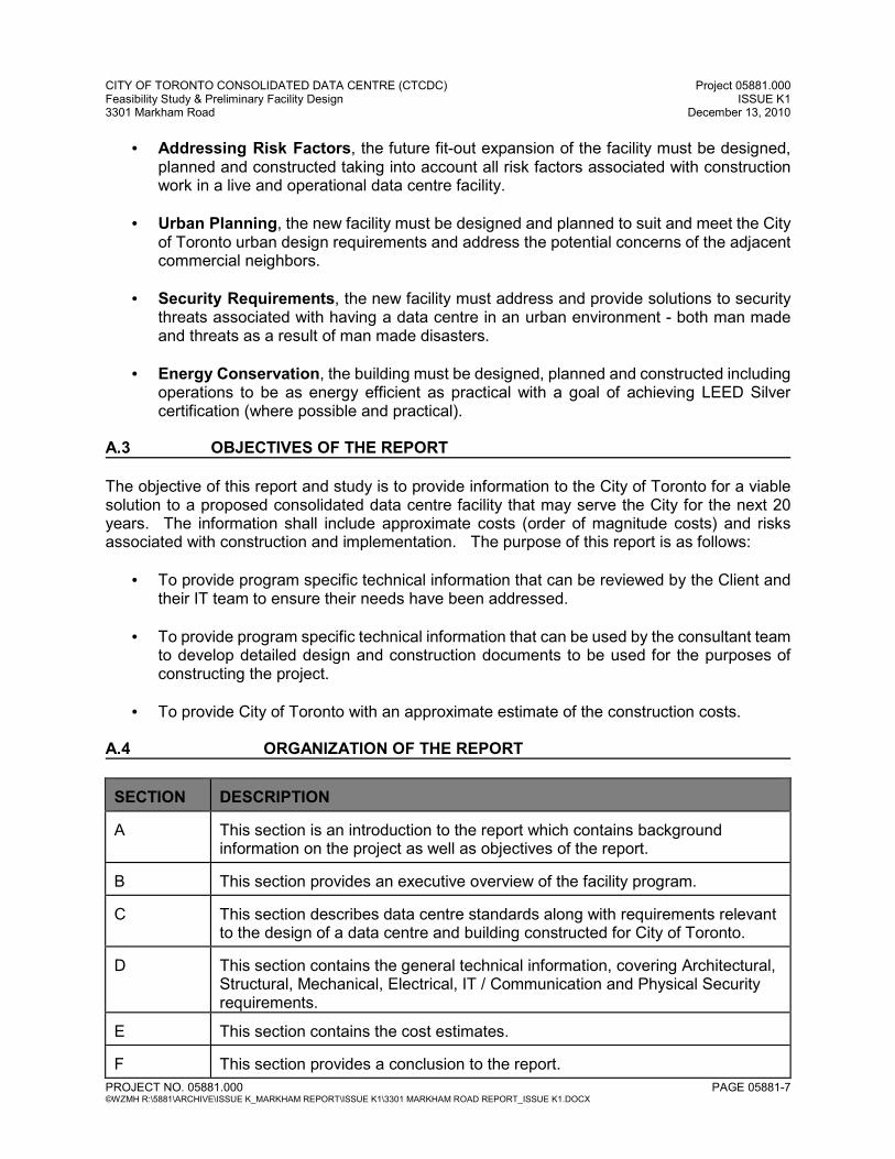
A.3 OBJECTIVES OF THE REPORT The objective of this report and study is to provide information to the City of Toronto for a viable solution to a proposed consolidated data centre facility that may serve the City for the next 20 years. The information shall include approximate costs (order of magnitude costs) and risks associated with construction and implementation. The purpose of this report is as follows:
• To provide program specific technical information that can be reviewed by the Client and their IT team to ensure their needs have been addressed.
• To provide program specific technical information that can be used by the consultant team
to develop detailed design and construction documents to be used for the purposes of constructing the project.
• To provide City of Toronto with an approximate estimate of the construction costs.
A.4 ORGANIZATION OF THE REPORT SECTION
DESCRIPTION
A
This section is an introduction to the report which contains background information on the project as well as objectives of the report.
B
This section provides an executive overview of the facility program.
C
This section describes data centre standards along with requirements relevant to the design of a data centre and building constructed for City of Toronto.
D
This section contains the general technical information, covering Architectural, Structural, Mechanical, Electrical, IT / Communication and Physical Security requirements.
E
This section contains the cost estimates.
F
This section provides a conclusion to the report.
CITY OF TORONTO CONSOLIDATED DATA CENTRE (CTCDC) Project 05881.000 Feasibility Study & Preliminary Facility Design ISSUE K1 3301 Markham Road December 13, 2010
PROJECT NO. 05881.000 PAGE 05881-8 ©WZMH R:\5881\ARCHIVE\ISSUE K_MARKHAM REPORT\ISSUE K1\3301 MARKHAM ROAD REPORT_ISSUE K1.DOCX
G
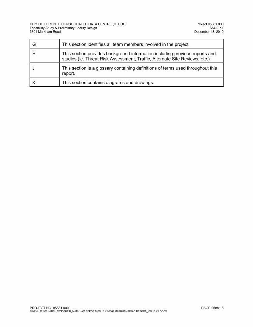
This section identifies all team members involved in the project.
H
This section provides background information including previous reports and studies (ie. Threat Risk Assessment, Traffic, Alternate Site Reviews, etc.)
J
This section is a glossary containing definitions of terms used throughout this report.
K
This section contains diagrams and drawings.
SECTION B
EXECUTIVE OVERVIEW OF THE FACILITY PROGRAM
CITY OF TORONTO CONSOLIDATED DATA CENTRE (CTCDC) Project 05881.000 Feasibility Study & Preliminary Facility Design ISSUE K1 3301 Markham Road December 13, 2010
PROJECT NO. 05881.000 PAGE 05881-9 ©WZMH R:\5881\ARCHIVE\ISSUE K_MARKHAM REPORT\ISSUE K1\3301 MARKHAM ROAD REPORT_ISSUE K1.DOCX
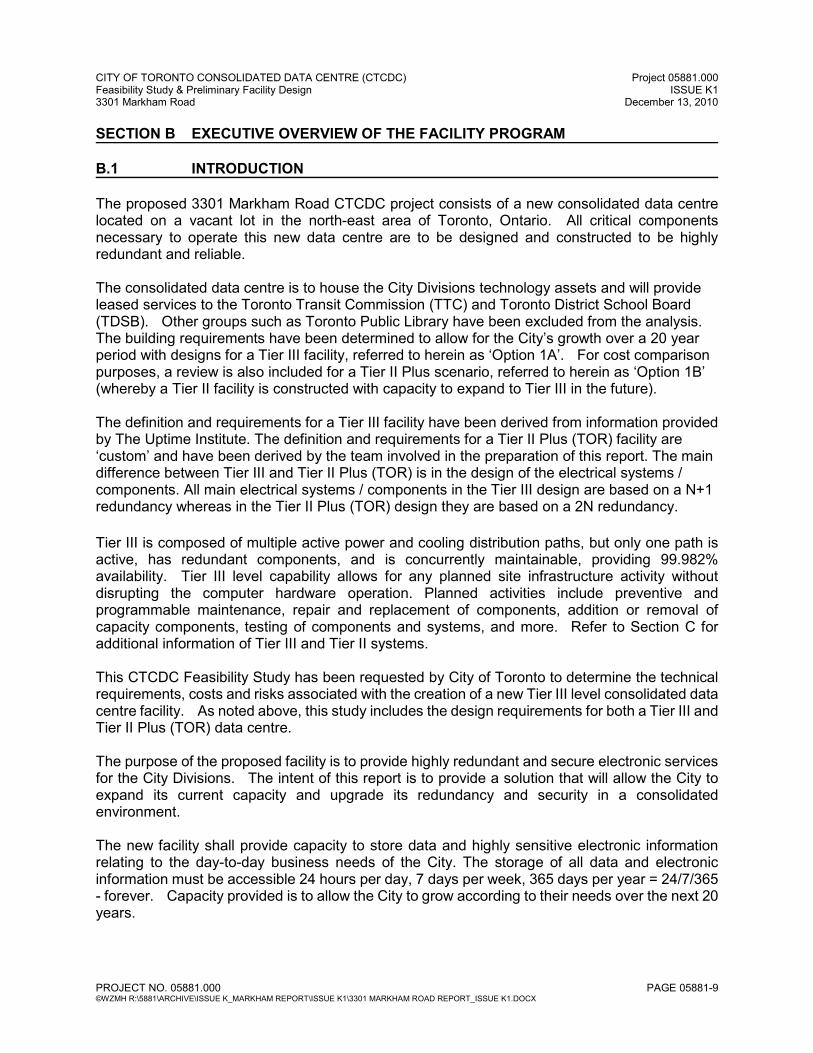
SECTION B EXECUTIVE OVERVIEW OF THE FACILITY PROGRAM B.1 INTRODUCTION
The proposed 3301 Markham Road CTCDC project consists of a new consolidated data centre located on a vacant lot in the north-east area of Toronto, Ontario. All critical components necessary to operate this new data centre are to be designed and constructed to be highly redundant and reliable. The consolidated data centre is to house the City Divisions technology assets and will provide leased services to the Toronto Transit Commission (TTC) and Toronto District School Board (TDSB). Other groups such as Toronto Public Library have been excluded from the analysis. The building requirements have been determined to allow for the City’s growth over a 20 year period with designs for a Tier III facility, referred to herein as ‘Option 1A’. For cost comparison purposes, a review is also included for a Tier II Plus scenario, referred to herein as ‘Option 1B’ (whereby a Tier II facility is constructed with capacity to expand to Tier III in the future). The definition and requirements for a Tier III facility have been derived from information provided by The Uptime Institute. The definition and requirements for a Tier II Plus (TOR) facility are ‘custom’ and have been derived by the team involved in the preparation of this report. The main difference between Tier III and Tier II Plus (TOR) is in the design of the electrical systems / components. All main electrical systems / components in the Tier III design are based on a N+1 redundancy whereas in the Tier II Plus (TOR) design they are based on a 2N redundancy.
Tier III is composed of multiple active power and cooling distribution paths, but only one path is active, has redundant components, and is concurrently maintainable, providing 99.982% availability. Tier III level capability allows for any planned site infrastructure activity without disrupting the computer hardware operation. Planned activities include preventive and programmable maintenance, repair and replacement of components, addition or removal of capacity components, testing of components and systems, and more. Refer to Section C for additional information of Tier III and Tier II systems. This CTCDC Feasibility Study has been requested by City of Toronto to determine the technical requirements, costs and risks associated with the creation of a new Tier III level consolidated data centre facility. As noted above, this study includes the design requirements for both a Tier III and Tier II Plus (TOR) data centre. The purpose of the proposed facility is to provide highly redundant and secure electronic services for the City Divisions. The intent of this report is to provide a solution that will allow the City to expand its current capacity and upgrade its redundancy and security in a consolidated environment. The new facility shall provide capacity to store data and highly sensitive electronic information relating to the day-to-day business needs of the City. The storage of all data and electronic information must be accessible 24 hours per day, 7 days per week, 365 days per year = 24/7/365 - forever. Capacity provided is to allow the City to grow according to their needs over the next 20 years.
CITY OF TORONTO CONSOLIDATED DATA CENTRE (CTCDC) Project 05881.000 Feasibility Study & Preliminary Facility Design ISSUE K1 3301 Markham Road December 13, 2010
PROJECT NO. 05881.000 PAGE 05881-10 ©WZMH R:\5881\ARCHIVE\ISSUE K_MARKHAM REPORT\ISSUE K1\3301 MARKHAM ROAD REPORT_ISSUE K1.DOCX
WZMH has been retained to conduct this Feasibility Report due primarily to its extensive experience and proven track record in the design, development and implementation of successful data centres across Ontario for both public and private organizations. B.1.1 Existing Facilities – Data Collection In order to properly prepare CTCDC for its intended role, an understanding of present computing loads must first be gained. Some growth will obviously be experienced in the interim period between 2010 and 2014 (anticipated date of completion). The computing environment that exists today will be different from the loads that will eventually be relocated to the new facility. With assistance from IBM Canada Ltd, Site and Facilities Services, comprehensive interviews have been conducted with each of the participating Division groups. Through the interview process, we tried to predict the magnitude of the loads that will need to be supported when the new facility is completed, and how those loads will grow over time. The difficultly of answering some of the questions is duly recognized. In many cases, it was not possible to provide predictions for future growth with a high degree of accuracy. However, it is also recognized that the people who are closest to each of the individual computer rooms are the only resources capable of providing even a reasonable prediction. Each of the interviews was documented and Minutes were distributed and verified (copies of Minutes are available upon request from WZMH). Refer to the following spreadsheets for a summary of anticipated energy consumption, space and power requirements (note information for Toronto Public Library has been removed from the below noted spreadsheets; refer to Appendix B-1 and B-2 in ISSUE C2: Decision Matrix, May 17, 2010):
• Summary of Anticipated Energy Consumption – see Section H below
• Summary of Space and Power Requirements – see Section H below
B.1.2 Decision Matrix One of the key tracking mechanisms in the process of determining performance and program requirements for CTCDC was the Decision Matrix (Issue C2, May 17, 2010). Refer to Section H below for a record of key decisions. Through comprehensive discussion, education seminars and refinement with project team members from City of Toronto, the Consultant team has developed an area chart and preliminary site plan drawings representative of the proposed facility. The following approximate space allocation has been determined (reference Issue G ‘Area Chart’, issued July 12, 2010):
• Facilities Management 2,412 sq.ft. (224 sq.m)
• Central Utilities Plant 79,474 sq.ft.(7,383 sq.m)
• Workstations 5,735 sq.ft. (533 sq.m)
• Office & Support Components 10,266 sq.ft. (954 sq.m)
• Loading Area 6,396 sq.ft. (594 sq.m)
CITY OF TORONTO CONSOLIDATED DATA CENTRE (CTCDC) Project 05881.000 Feasibility Study & Preliminary Facility Design ISSUE K1 3301 Markham Road December 13, 2010
PROJECT NO. 05881.000 PAGE 05881-11 ©WZMH R:\5881\ARCHIVE\ISSUE K_MARKHAM REPORT\ISSUE K1\3301 MARKHAM ROAD REPORT_ISSUE K1.DOCX
• Data Centre and Mechanical Corridors 45,624 sq.ft. (4,238 sq.m)
• TOTAL approximate building area 152,906 sq.ft. (14,205 sq.m)
Total anticipated whitespace (data hall) area and associated power draw is noted below for
reference (per Appendix B, Vol. 2). These values were determined as part of the IBM data
collection process (see B.1.1 above):
• Year 2010: 14,410 sq.ft., 717 kW
• Year 2014: 18,650 sq.ft., 1,825 kW
• Year 2024: 24,570 sq.ft., 3,465 kW
• Year 2034: 31,110 sq.ft., 5,838 kW
• Year 2044: 33,160 sq.ft., 7,081 kW
B.2 WATTS / S.F. The WATTS / S.F. identified in this report for all phases is a general indication of gross raised floor power density allocate for the IT computing equipment use only. Based on interviews and data collected from all the City divisions, the IT equipment rack power density for 2014 is estimated to range from a minimum of 1.7KW to a maximum of 3.00KW per rack. For year 2024, the IT equipment rack power density is projected to be in the range of 2kw to 5KW, and for year 2034, the IT equipment rack power density is projected to be in the range of 2kw to 8Kw. Based on the IT equipment rack power density, the intent of CTCDC is to provide an initial gross floor usable power density of 98 watts per SF expandable to 188 watts per SF at the end of year 2034. B.3 FUTURE GROWTH CTCDC is based on a design and construction plan that is phased over a 20 year period. The planning and construction of the project must be such that there will be minimum service interruption and downtime to the new facility and operations as the facility undergoes expansion (within building shell) in the future phase(s). In order to ensure minimum service interruption and downtime during all phases, the project should be designed to include all major architectural and structural additions within the first phase (Day One) and includes additional space to suit future mechanical and electrical requirements. The following provisions are required in the design of CTCDC to ensure that all future phases where additional mechanical and electrical components are required can be installed and commissioned with minimum service interruption and downtime to the existing facility:
• Service corridors that are designed with additional ‘width’ and clear heights to allow the movement of equipment into the building to the final location.
• The proposed pathway from the exterior wall to the final ‘resting’ position of all future
mechanical and electrical equipment must be designed to allow sufficient headroom including door heights and clearances to existing ceiling services. The pathway must be
CITY OF TORONTO CONSOLIDATED DATA CENTRE (CTCDC) Project 05881.000 Feasibility Study & Preliminary Facility Design ISSUE K1 3301 Markham Road December 13, 2010
PROJECT NO. 05881.000 PAGE 05881-12 ©WZMH R:\5881\ARCHIVE\ISSUE K_MARKHAM REPORT\ISSUE K1\3301 MARKHAM ROAD REPORT_ISSUE K1.DOCX
structurally designed to accommodate the loads imposed by ‘rolling’ the mechanical and electrical equipment into place.
• Building envelope (exterior wall) that includes provisions to easily remove the cladding
and interior concrete block wall to allow equipment to be installed into the building. The interior concrete block wall of the exterior wall is to be designed and constructed as a knock-out panel (with lintels) that can easily be removed and replaced when required.
• In areas where the new mechanical and electrical components will be installed via the roof
(i.e. overhead crane), the roof structure must be designed and constructed with a steel framing system with main structural members sufficiently spaced to allow the equipment to pass and lower freely into the building. In areas where future components will be lowered through the roof, the design of the waterproofing should include curbs where the waterproofing terminates on either side in a vertical position - this will allow a portion of the roof to be removed without compromising the integrity of the waterproofing assembly. Refer also to Structural Requirements below.
• The intent of having minimum service interruption and downtime to the mechanical and
electrical components and systems (CUP) during all future phasing is to ensure that the data centre is not compromised with respect to redundancy and reliability. Staging of future mechanical and electrical expansion to within CTCDC envelope has to be carefully planned and executed in order to ensure the facility remains fully operational and the Raised Floor (“White Space”) and CUP have minimum service interruption and downtime. It is generally assumed that a temporary wall is to divide the fitted out Day One data hall from the shelled Data hall area.
The recommendations presented in this study outline the technical criteria and possible solutions to complete the design of a reliable data centre - phased over 20 years. The facility is flexible in that a multi-tiered DC can be implemented and additional build-out on the second level may be accommodated (the 2nd Floor plate is currently smaller than the Ground Floor plate). With the recommendations presented and risks outlined, City of Toronto could move forward into the next stages (design and construction) if they feel that this project is considered a viable solution from a business development point of view. Some factors to be considered prior to proceeding with the next stages include:
• The proposed design has not yet been formally reviewed by the City of Toronto with respect to zoning by-law requirements, however, a series of discussions / conceptual reviews with the City Planning Division have allowed us to intelligently locate the building and its pedestrian/vehicular access points on the site. The proposed design will most likely require a site-specific zoning by-law amendment to address zoning classification, parking, setbacks, coverage, etc. The site is currently zoned for Agricultural use.
• The project involves a new highly available and redundant data centre that will be located
in a busy sub-urban environment. The project also fronts major access routes in north-east Toronto that are accessible by the public (Markham Road and Steeles Avenue West). Physical security of the facility and its inhabitants was reviewed in detail and reports are included in Volume 2. With the implementation of some hardening measures, balanced survivability is achievable. Various recommendations to achieve optimum security were made. Some key points include:
CITY OF TORONTO CONSOLIDATED DATA CENTRE (CTCDC) Project 05881.000 Feasibility Study & Preliminary Facility Design ISSUE K1 3301 Markham Road December 13, 2010
PROJECT NO. 05881.000 PAGE 05881-13 ©WZMH R:\5881\ARCHIVE\ISSUE K_MARKHAM REPORT\ISSUE K1\3301 MARKHAM ROAD REPORT_ISSUE K1.DOCX
o Constructing the facility with a hardened shell to achieve the desired Target Levels
of Safety. A layered approach with both physical security measures and blast hardening would be required.
o Relocation of the parking lot to maximize the setback of the building from any parked or moving vehicle)
o Hardening of the entrance vestibule with controlled views o Barrier with card access / screening mechanism for vehicles entering the site o Additional recommendations are made in the CBRN report, Blast Design
Hardening Measures, and Physical Security Design Brief / TRA dated June 30th (see Vol.2)
• Unused CUP space for future mechanical and electrical equipment may not be sufficiently
utilized. Shell space is designed to be fitted out in stages over 20 years and cannot be used for storage of paper items etc.
B.4 NEXT STEPS Assuming City of Toronto wishes to proceed with this project, further development of the design of one of the Options (either Tier III or Tier II Plus) is required. Further development includes detailed Schematic Design, Design Development and Working Drawings (Contract Documents) where all proposed areas are confirmed against detailed design solutions. In addition to detailed design, the overall massing of the proposed design would have to be reviewed by the City of Toronto with respect to zoning by-law requirements. Refer to Section F for conclusions, risks and challenges associated with this project. Additionally, consideration should be given to the method of procurement for actually constructing the facility. Various procurement methods, such as traditional, design-build, DBFM and P3, are available with their associated unique pros and cons. Review and comparison of these different methods of procurement are outside the scope of this report. Subsequent to the completion of this Study, it has been determined that the projected construction costs, as outlined in Section E, are in excess of the stipulated $80M budget. The WZMH consultant team has been requested to revisit the proposed solution herein and apply cost reduction strategies towards providing alternative Options within budget. A forthcoming report shall address these cost reduction strategies.
SECTION C BASIS FOR THE DESIGN OF THE FACILITY
CITY OF TORONTO CONSOLIDATED DATA CENTRE (CTCDC) Project 05881.000 Feasibility Study & Preliminary Facility Design ISSUE K1 3301 Markham Road December 13, 2010
PROJECT NO. 05881.000 PAGE 05881-14 ©WZMH R:\5881\ARCHIVE\ISSUE K_MARKHAM REPORT\ISSUE K1\3301 MARKHAM ROAD REPORT_ISSUE K1.DOCX
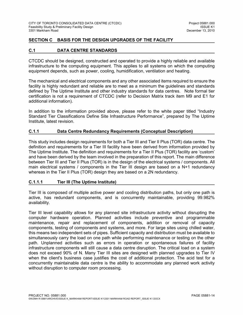
SECTION C BASIS FOR THE DESIGN UPGRADES OF THE FACILITY C.1 DATA CENTRE STANDARDS CTCDC should be designed, constructed and operated to provide a highly reliable and available infrastructure to the computing equipment. This applies to all systems on which the computing equipment depends, such as power, cooling, humidification, ventilation and heating. The mechanical and electrical components and any other associated items required to ensure the facility is highly redundant and reliable are to meet as a minimum the guidelines and standards defined by The Uptime Institute and other industry standards for data centres. Note formal tier certification is not a requirement of CTCDC (refer to Decision Matrix track item M9 and E1 for additional information). In addition to the information provided above, please refer to the white paper titled “Industry Standard Tier Classifications Define Site Infrastructure Performance”, prepared by The Uptime Institute, latest revision. C.1.1 Data Centre Redundancy Requirements (Conceptual Description) This study includes design requirements for both a Tier III and Tier II Plus (TOR) data centre. The definition and requirements for a Tier III facility have been derived from information provided by The Uptime Institute. The definition and requirements for a Tier II Plus (TOR) facility are ‘custom’ and have been derived by the team involved in the preparation of this report. The main difference between Tier III and Tier II Plus (TOR) is in the design of the electrical systems / components. All main electrical systems / components in the Tier III design are based on a N+1 redundancy whereas in the Tier II Plus (TOR) design they are based on a 2N redundancy. C.1.1.1 Tier III (The Uptime Institute) Tier III is composed of multiple active power and cooling distribution paths, but only one path is active, has redundant components, and is concurrently maintainable, providing 99.982% availability. Tier III level capability allows for any planned site infrastructure activity without disrupting the computer hardware operation. Planned activities include preventive and programmable maintenance, repair and replacement of components, addition or removal of capacity components, testing of components and systems, and more. For large sites using chilled water, this means two independent sets of pipes. Sufficient capacity and distribution must be available to simultaneously carry the load on one path while performing maintenance or testing on the other path. Unplanned activities such as errors in operation or spontaneous failures of facility infrastructure components will still cause a data centre disruption. The critical load on a system does not exceed 90% of N. Many Tier III sites are designed with planned upgrades to Tier IV when the client's business case justifies the cost of additional protection. The acid test for a concurrently maintainable data centre is the ability to accommodate any planned work activity without disruption to computer room processing.
CITY OF TORONTO CONSOLIDATED DATA CENTRE (CTCDC) Project 05881.000 Feasibility Study & Preliminary Facility Design ISSUE K1 3301 Markham Road December 13, 2010
PROJECT NO. 05881.000 PAGE 05881-15 ©WZMH R:\5881\ARCHIVE\ISSUE K_MARKHAM REPORT\ISSUE K1\3301 MARKHAM ROAD REPORT_ISSUE K1.DOCX
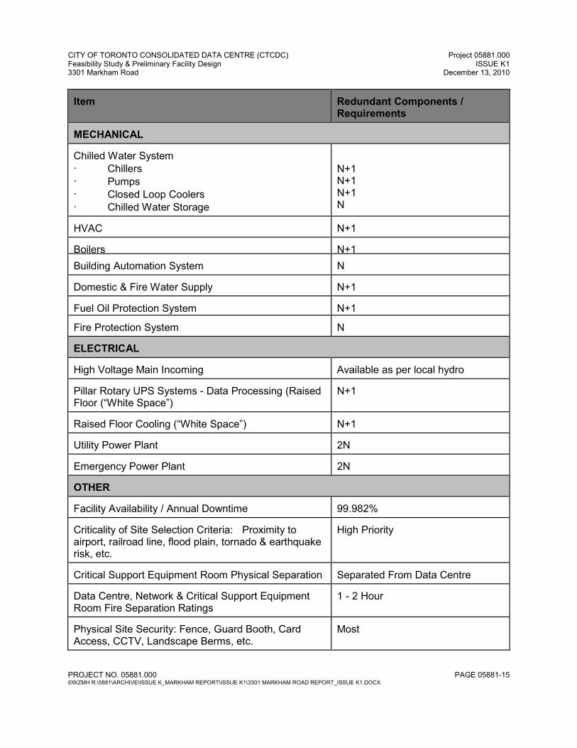
Item
Redundant Components / Requirements
MECHANICAL Chilled Water System · Chillers · Pumps · Closed Loop Coolers · Chilled Water Storage
N+1 N+1 N+1 N
HVAC
N+1
Boilers
N+1
Building Automation System
N
Domestic & Fire Water Supply
N+1
Fuel Oil Protection System
N+1
Fire Protection System
N
ELECTRICAL High Voltage Main Incoming
Available as per local hydro
Pillar Rotary UPS Systems - Data Processing (Raised Floor (“White Space”)
N+1
Raised Floor Cooling (“White Space”)
N+1
Utility Power Plant
2N
Emergency Power Plant
2N
OTHER Facility Availability / Annual Downtime
99.982%
Criticality of Site Selection Criteria: Proximity to airport, railroad line, flood plain, tornado & earthquake risk, etc.
High Priority
Critical Support Equipment Room Physical Separation
Separated From Data Centre
Data Centre, Network & Critical Support Equipment Room Fire Separation Ratings
1 - 2 Hour
Physical Site Security: Fence, Guard Booth, Card Access, CCTV, Landscape Berms, etc.
Most
CITY OF TORONTO CONSOLIDATED DATA CENTRE (CTCDC) Project 05881.000 Feasibility Study & Preliminary Facility Design ISSUE K1 3301 Markham Road December 13, 2010
PROJECT NO. 05881.000 PAGE 05881-16 ©WZMH R:\5881\ARCHIVE\ISSUE K_MARKHAM REPORT\ISSUE K1\3301 MARKHAM ROAD REPORT_ISSUE K1.DOCX
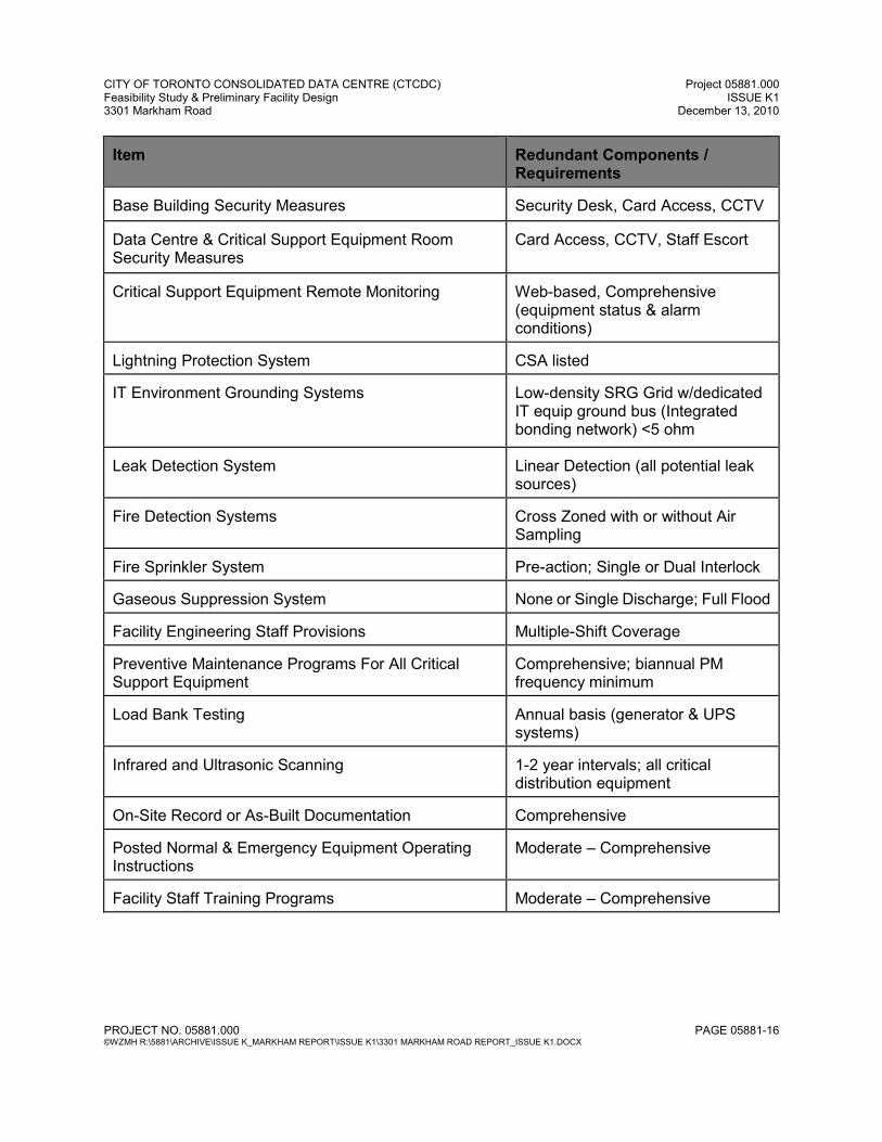
Item
Redundant Components / Requirements
Base Building Security Measures
Security Desk, Card Access, CCTV
Data Centre & Critical Support Equipment Room Security Measures
Card Access, CCTV, Staff Escort
Critical Support Equipment Remote Monitoring
Web-based, Comprehensive (equipment status & alarm conditions)
Lightning Protection System
CSA listed
IT Environment Grounding Systems
Low-density SRG Grid w/dedicated IT equip ground bus (Integrated bonding network) <5 ohm
Leak Detection System
Linear Detection (all potential leak sources)
Fire Detection Systems
Cross Zoned with or without Air Sampling
Fire Sprinkler System
Pre-action; Single or Dual Interlock
Gaseous Suppression System
None or Single Discharge; Full Flood
Facility Engineering Staff Provisions
Multiple-Shift Coverage
Preventive Maintenance Programs For All Critical Support Equipment
Comprehensive; biannual PM frequency minimum
Load Bank Testing
Annual basis (generator & UPS systems)
Infrared and Ultrasonic Scanning
1-2 year intervals; all critical distribution equipment
On-Site Record or As-Built Documentation
Comprehensive
Posted Normal & Emergency Equipment Operating Instructions
Moderate – Comprehensive
Facility Staff Training Programs
Moderate – Comprehensive
CITY OF TORONTO CONSOLIDATED DATA CENTRE (CTCDC) Project 05881.000 Feasibility Study & Preliminary Facility Design ISSUE K1 3301 Markham Road December 13, 2010
PROJECT NO. 05881.000 PAGE 05881-17 ©WZMH R:\5881\ARCHIVE\ISSUE K_MARKHAM REPORT\ISSUE K1\3301 MARKHAM ROAD REPORT_ISSUE K1.DOCX
C.1.1.2 Tier II Plus (TOR) A Class ‘D’ cost estimate has been provided in this report for a Tier II Plus facility (see Section E). While technical information and details are omitted in this report for a Tier II Plus facility it should be noted that the area requirements for a Tier II Plus facility are the same as those required for a Tier III facility and the mechanical components do not change. There are some electrical shortfalls between the Tier II Plus and Tier III facility that would have to be addressed in more detail should City of Toronto wish to pursue the Tier II Plus option. The Tier II Plus (TOR) electrical systems will incorporate redundant capacity systems for utility power, emergency power, and UPS power supplies, with dual or multiple simultaneously energized power distribution paths supporting the facilities computer equipment. All IT equipment will be dual fed (dual corded IT equipment or point of use transfer device for single cord IT equipment have been assumed). The failure of any single capacity system will not affect the computer equipment. All electrical components or systems are concurrent maintainable non-disruptive to computer operations. Mechanically, Tier II Plus (TOR) requires one 'system' for each component (i.e. cooling plant), with N+1 equipment, one active and one manually activated alternate path, with the alternate path physically separate (compartmentalized) from the active path, and the ability to concurrently maintain any single piece of equipment. C.1.2 ASHRAE & CSA Standards CTCDC must be designed mechanically and electrically (including architectural components) taking into account the minimum standards set forth in the following ASHRAE and CSA standards:
• ASHRAE 90.1 - 1999 Energy Standard • ASHRAE 62 - 2001 - Ventilation for Acceptable Indoor Air Quality • CSA-B52 - Mechanical Refrigeration Safety Code
C.2 ENERGY EFFICIENCY An important goal for the design and construction of CTCDC is to meet the latest industry standards relating to energy efficiency, sustainability and environmental design. These standards will affect nearly all aspects of the design, construction and operation of the facility and, to be truly effective, should permeate the work of all disciplines and be ever-present in the decision making processes. To measure and verify performance in this regard, the Leadership in Energy & Environmental Design (LEED Canada-NC) rating system will be used. (If possible and practical, the project is to be designed, constructed and certified under the LEED Canada NC Green Building Rating System - Silver rating.)
CITY OF TORONTO CONSOLIDATED DATA CENTRE (CTCDC) Project 05881.000 Feasibility Study & Preliminary Facility Design ISSUE K1 3301 Markham Road December 13, 2010
PROJECT NO. 05881.000 PAGE 05881-18 ©WZMH R:\5881\ARCHIVE\ISSUE K_MARKHAM REPORT\ISSUE K1\3301 MARKHAM ROAD REPORT_ISSUE K1.DOCX
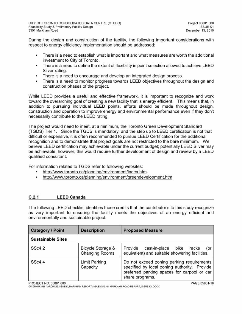
During the design and construction of the facility, the following important considerations with respect to energy efficiency implementation should be addressed:
• There is a need to establish what is important and what measures are worth the additional investment to City of Toronto.
• There is a need to define the extent of flexibility in point selection allowed to achieve LEED Silver rating.
• There is a need to encourage and develop an integrated design process. • There is a need to monitor progress towards LEED objectives throughout the design and
construction phases of the project. While LEED provides a useful and effective framework, it is important to recognize and work toward the overarching goal of creating a new facility that is energy efficient. This means that, in addition to pursuing individual LEED points, efforts should be made throughout design, construction and operation to improve energy and environmental performance even if they don't necessarily contribute to the LEED rating. The project would need to meet, at a minimum, the Toronto Green Development Standard (TGDS) Tier 1. Since the TGDS is mandatory, and the step up to LEED certification is not that difficult or expensive, it is often recommended to pursue LEED Certification for the additional recognition and to demonstrate that project goals are not restricted to the bare minimum. We believe LEED certification may achievable under the current budget; potentially LEED Silver may be achievable, however, this would require further development of design and review by a LEED qualified consultant. For information related to TGDS refer to following websites:
• http://www.toronto.ca/planning/environment/index.htm • http://www.toronto.ca/planning/environment/greendevelopment.htm
C.2.1 LEED Canada The following LEED checklist identifies those credits that the contributor’s to this study recognize as very important to ensuring the facility meets the objectives of an energy efficient and environmentally and sustainable project: Category / Point
Description
Proposed Measure
Sustainable Sites SSc4.2
Bicycle Storage & Changing Rooms
Provide cast-in-place bike racks (or equivalent) and suitable showering facilities.
SSc4.4
Limit Parking Capacity
Do not exceed zoning parking requirements specified by local zoning authority. Provide preferred parking spaces for carpool or car share programs.
CITY OF TORONTO CONSOLIDATED DATA CENTRE (CTCDC) Project 05881.000 Feasibility Study & Preliminary Facility Design ISSUE K1 3301 Markham Road December 13, 2010
PROJECT NO. 05881.000 PAGE 05881-19 ©WZMH R:\5881\ARCHIVE\ISSUE K_MARKHAM REPORT\ISSUE K1\3301 MARKHAM ROAD REPORT_ISSUE K1.DOCX
Category / Point
Description
Proposed Measure
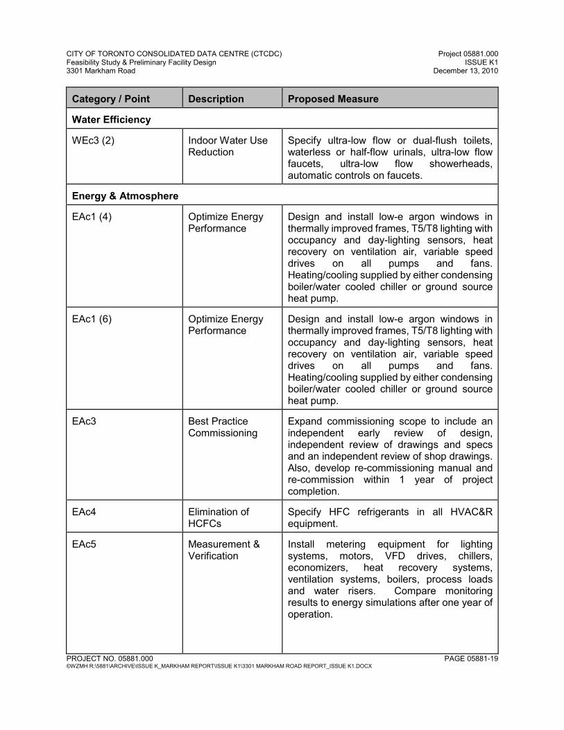
Water Efficiency WEc3 (2)
Indoor Water Use Reduction
Specify ultra-low flow or dual-flush toilets, waterless or half-flow urinals, ultra-low flow faucets, ultra-low flow showerheads, automatic controls on faucets.
Energy & Atmosphere EAc1 (4)
Optimize Energy Performance
Design and install low-e argon windows in thermally improved frames, T5/T8 lighting with occupancy and day-lighting sensors, heat recovery on ventilation air, variable speed drives on all pumps and fans. Heating/cooling supplied by either condensing boiler/water cooled chiller or ground source heat pump.
EAc1 (6)
Optimize Energy Performance
Design and install low-e argon windows in thermally improved frames, T5/T8 lighting with occupancy and day-lighting sensors, heat recovery on ventilation air, variable speed drives on all pumps and fans. Heating/cooling supplied by either condensing boiler/water cooled chiller or ground source heat pump.
EAc3
Best Practice Commissioning
Expand commissioning scope to include an independent early review of design, independent review of drawings and specs and an independent review of shop drawings. Also, develop re-commissioning manual and re-commission within 1 year of project completion.
EAc4
Elimination of HCFCs
Specify HFC refrigerants in all HVAC&R equipment.
EAc5
Measurement & Verification
Install metering equipment for lighting systems, motors, VFD drives, chillers, economizers, heat recovery systems, ventilation systems, boilers, process loads and water risers. Compare monitoring results to energy simulations after one year of operation.
CITY OF TORONTO CONSOLIDATED DATA CENTRE (CTCDC) Project 05881.000 Feasibility Study & Preliminary Facility Design ISSUE K1 3301 Markham Road December 13, 2010
PROJECT NO. 05881.000 PAGE 05881-20 ©WZMH R:\5881\ARCHIVE\ISSUE K_MARKHAM REPORT\ISSUE K1\3301 MARKHAM ROAD REPORT_ISSUE K1.DOCX
Category / Point
Description
Proposed Measure
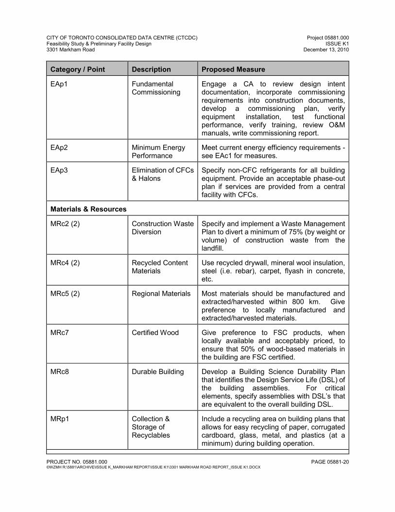
EAp1
Fundamental Commissioning
Engage a CA to review design intent documentation, incorporate commissioning requirements into construction documents, develop a commissioning plan, verify equipment installation, test functional performance, verify training, review O&M manuals, write commissioning report.
EAp2
Minimum Energy Performance
Meet current energy efficiency requirements - see EAc1 for measures.
EAp3
Elimination of CFCs & Halons
Specify non-CFC refrigerants for all building equipment. Provide an acceptable phase-out plan if services are provided from a central facility with CFCs.
Materials & Resources MRc2 (2)
Construction Waste Diversion
Specify and implement a Waste Management Plan to divert a minimum of 75% (by weight or volume) of construction waste from the landfill.
MRc4 (2)
Recycled Content Materials
Use recycled drywall, mineral wool insulation, steel (i.e. rebar), carpet, flyash in concrete, etc.
MRc5 (2)
Regional Materials
Most materials should be manufactured and extracted/harvested within 800 km. Give preference to locally manufactured and extracted/harvested materials.
MRc7
Certified Wood
Give preference to FSC products, when locally available and acceptably priced, to ensure that 50% of wood-based materials in the building are FSC certified.
MRc8
Durable Building
Develop a Building Science Durability Plan that identifies the Design Service Life (DSL) of the building assemblies. For critical elements, specify assemblies with DSL’s that are equivalent to the overall building DSL.
MRp1
Collection & Storage of Recyclables
Include a recycling area on building plans that allows for easy recycling of paper, corrugated cardboard, glass, metal, and plastics (at a minimum) during building operation.
CITY OF TORONTO CONSOLIDATED DATA CENTRE (CTCDC) Project 05881.000 Feasibility Study & Preliminary Facility Design ISSUE K1 3301 Markham Road December 13, 2010
PROJECT NO. 05881.000 PAGE 05881-21 ©WZMH R:\5881\ARCHIVE\ISSUE K_MARKHAM REPORT\ISSUE K1\3301 MARKHAM ROAD REPORT_ISSUE K1.DOCX
Category / Point
Description
Proposed Measure
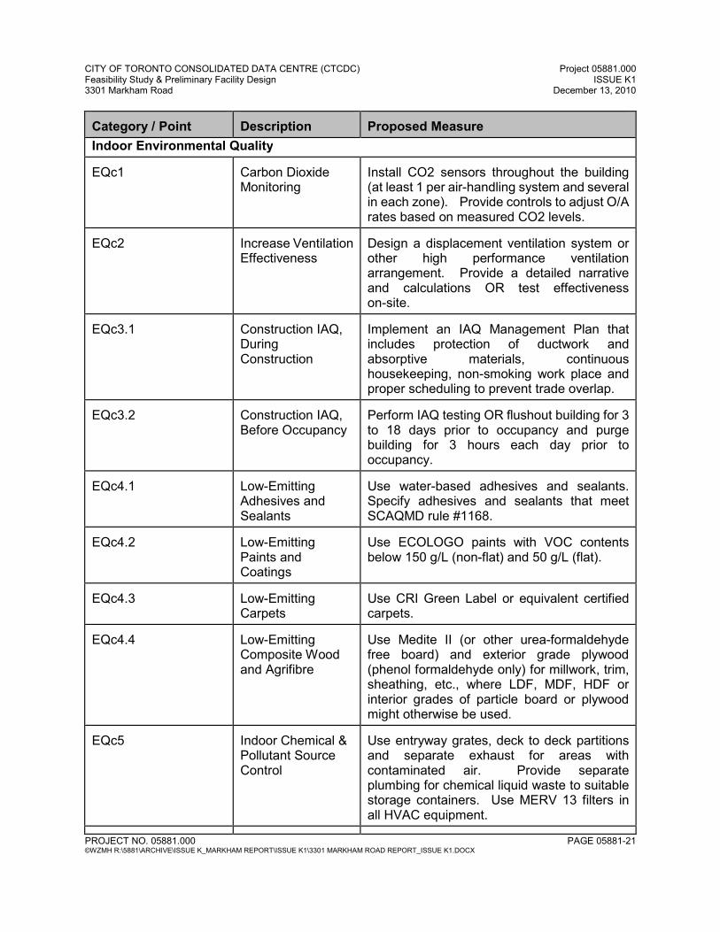
Indoor Environmental Quality EQc1
Carbon Dioxide Monitoring
Install CO2 sensors throughout the building (at least 1 per air-handling system and several in each zone). Provide controls to adjust O/A rates based on measured CO2 levels.
EQc2
Increase Ventilation Effectiveness
Design a displacement ventilation system or other high performance ventilation arrangement. Provide a detailed narrative and calculations OR test effectiveness on-site.
EQc3.1
Construction IAQ, During Construction
Implement an IAQ Management Plan that includes protection of ductwork and absorptive materials, continuous housekeeping, non-smoking work place and proper scheduling to prevent trade overlap.
EQc3.2
Construction IAQ, Before Occupancy
Perform IAQ testing OR flushout building for 3 to 18 days prior to occupancy and purge building for 3 hours each day prior to occupancy.
EQc4.1
Low-Emitting Adhesives and Sealants
Use water-based adhesives and sealants. Specify adhesives and sealants that meet SCAQMD rule #1168.
EQc4.2
Low-Emitting Paints and Coatings
Use ECOLOGO paints with VOC contents below 150 g/L (non-flat) and 50 g/L (flat).
EQc4.3
Low-Emitting Carpets
Use CRI Green Label or equivalent certified carpets.
EQc4.4
Low-Emitting Composite Wood and Agrifibre
Use Medite II (or other urea-formaldehyde free board) and exterior grade plywood (phenol formaldehyde only) for millwork, trim, sheathing, etc., where LDF, MDF, HDF or interior grades of particle board or plywood might otherwise be used.
EQc5
Indoor Chemical & Pollutant Source Control
Use entryway grates, deck to deck partitions and separate exhaust for areas with contaminated air. Provide separate plumbing for chemical liquid waste to suitable storage containers. Use MERV 13 filters in all HVAC equipment.
CITY OF TORONTO CONSOLIDATED DATA CENTRE (CTCDC) Project 05881.000 Feasibility Study & Preliminary Facility Design ISSUE K1 3301 Markham Road December 13, 2010
PROJECT NO. 05881.000 PAGE 05881-22 ©WZMH R:\5881\ARCHIVE\ISSUE K_MARKHAM REPORT\ISSUE K1\3301 MARKHAM ROAD REPORT_ISSUE K1.DOCX
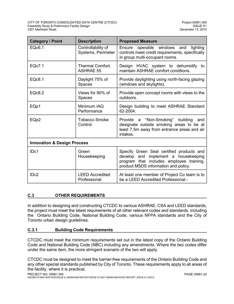
Category / Point
Description
Proposed Measure
EQc6.1 Controllability of Systems, Perimeter
Ensure operable windows and lighting controls meet credit requirements, specifically in group multi-occupant rooms.
EQc7.1
Thermal Comfort, ASHRAE 55
Design HVAC system to dehumidify to maintain ASHRAE comfort conditions.
EQc8.1
Daylight 75% of Spaces
Provide daylighting using north-facing glazing (windows and skylights).
EQc8.2
Views for 90% of Spaces
Provide open concept rooms with views to the outdoors.
EQp1
Minimum IAQ Performance
Design building to meet ASHRAE Standard 62-2004.
EQp2
Tobacco Smoke Control
Provide a “Non-Smoking” building and designate outside smoking areas to be at least 7.5m away from entrance areas and air intakes.
Innovation & Design Process IDc1
Green Housekeeping
Specify Green Seal certified products and develop and implement a housekeeping program that includes employee training, product MSDS information and policy.
IDc2
LEED Accredited Professional
At least one member of Project Co team is to be a LEED Accredited Professional.-
C.3 OTHER REQUIREMENTS In addition to designing and constructing CTCDC to various ASHRAE, CSA and LEED standards, the project must meet the latest requirements of all other relevant codes and standards, including the Ontario Building Code, National Building Code, various NFPA standards and the City of Toronto urban design guidelines. C.3.1 Building Code Requirements CTCDC must meet the minimum requirements set out in the latest copy of the Ontario Building Code and National Building Code (NBC) including any amendments. Where the two codes differ under the same item, the more stringent scenario of the two will apply. CTCDC must be designed to meet the barrier-free requirements of the Ontario Building Code and any other special standards published by City of Toronto. These requirements apply to all areas of the facility, where it is practical.
CITY OF TORONTO CONSOLIDATED DATA CENTRE (CTCDC) Project 05881.000 Feasibility Study & Preliminary Facility Design ISSUE K1 3301 Markham Road December 13, 2010
PROJECT NO. 05881.000 PAGE 05881-23 ©WZMH R:\5881\ARCHIVE\ISSUE K_MARKHAM REPORT\ISSUE K1\3301 MARKHAM ROAD REPORT_ISSUE K1.DOCX
The requirements for barrier-free accessibility are to include all areas of the building that can be accessible via staff and visitors regardless of their security clearance and/or security level. All areas accessible via staff and visitors are to be designed and constructed to address both physical, visual and hearing disabilities and challenges. The design must address all components of the building, including finishes, millwork, room sizes, circulation and furniture (FF&E). The CUP and any other associated mechanical and electrical rooms / spaces are not required to be designed to meet the requirements of the documents noted above, however as a minimum, the design and construction of the CUP (and associated components) should include the following:
• One access point to the CUP from other components of the building should be barrier-free accessible.
• All circulation paths (corridors) within the CUP should be barrier free accessible. • Any new facility management (operations room, locker rooms, etc.) should be barrier free
accessible. Although the CUP and the rooms within the CUP are not practical to be designed to be barrier free, the design should ensure as best as possible to allow these spaces to be accessible.

SECTION D DATA CENTRE REQUIREMENTS
CITY OF TORONTO CONSOLIDATED DATA CENTRE (CTCDC) Project 05881.000 Feasibility Study & Preliminary Facility Design ISSUE K1 3301 Markham Road December 13, 2010
PROJECT NO. 05881.000 PAGE 05881-24 ©WZMH R:\5881\ARCHIVE\ISSUE K_MARKHAM REPORT\ISSUE K1\3301 MARKHAM ROAD REPORT_ISSUE K1.DOCX
SECTION D DATA CENTRE REQUIREMENTS D.1 SITE UPGRADES CTCDC involves the construction of a new facility at the south side of the property and will therefore require upgrades to the site with respect to traffic circulation, mechanical and electrical requirements. Please note the following considerations:
• The stormwater management requirements for the development of sites within the City of Toronto are trigged when a Site Plan and/or Re-Zoning application is required. The City’s Wet Weather Flow Guidelines indicate the criteria to which a site is assessed to satisfy the guidelines. The criteria is:
o Post-development storm drainage from a site must be controlled to the
pre-development 2 year return period storm event with a maximum run-off coefficient of 0.5 for all storm events up to and including the 100 year return period storm.
• Based on this requirement it may be necessary to provide detention storage on site which
can be in the form of roof top and/or surface e.g. ponds and parking lots. If these types of storage are not viable or are desirable for the site, a detention tank or cistern can be used.
• The Wet Weather Flow Guidelines also required that water quality and water balance be
addressed for the site.
• Stormwater quality is to Level 1 or to the enhance level as per MOE requirements which is 80% removals of TSS.
• Water balance is addressed usually by retaining 5mm of rainfall from every event and
reusing the water for irrigation.
• The option of using the SWM pond adjacent to the site for heat rejection was considered and rejected as it is not adequately sized for this purpose and introduces undesirable risks.
• There is no existing water connection to the site. A new connection is required from an
existing water main in the vicinity.
• The water supply system is reliable and can supply the required water for the full build-out. Water is stored on site in remote cooling tower sumps to maintain cooling tower operation for minimum 12 hours in the event of interruption of the municipal supply (refer to Mechanical Requirements). It is to be determined whether a backup well is permitted on the site and whether sufficient flow would be available to serve as a viable backup to the municipal supply.
• A new sanitary sewer connection will be required.
CITY OF TORONTO CONSOLIDATED DATA CENTRE (CTCDC) Project 05881.000 Feasibility Study & Preliminary Facility Design ISSUE K1 3301 Markham Road December 13, 2010
PROJECT NO. 05881.000 PAGE 05881-25 ©WZMH R:\5881\ARCHIVE\ISSUE K_MARKHAM REPORT\ISSUE K1\3301 MARKHAM ROAD REPORT_ISSUE K1.DOCX
• Refer to Mechanical Site Servicing Requirements for additional considerations (Section D.4.2)
• Refer to Electrical Requirements for additional considerations (Section D.5)
D.1.1 Electrical Infrastructure
Toronto Hydro Electric Limited, THES advise that only one 27.6KV feeder power supply fed from the nearby Transformer Substation is available for this site. Diverse 27.6KV feeders from difference TS or from different HV Power Transformers within the same TS are not available at this site.
One THES 27.6KV feeder will enter the site to CTCDC Main Incoming Hydro Room via concrete
encased ductbank structure (one cable per duct). One set of spare ducts and one 2” spare duct
shall also be provided for future use.
The 27.6KV incoming service will terminate at the main load break switches at the 27.6kV Main
Incoming Switchgear, complete with dedicated THES Metering section, fused load break switch
(serve as THES customer demarcation point) and four (4) 27.6KV branch vacuum breakers to
serve the CTCDC Data centre , and the supporting facilities.
1. THES Revenue metering will be metered at 27.6kV and a Measurement Canada
approved power quality meter as part of the Data Centre PMCS system will be
provided to meter all of the 27.6kV branch feeder for power quality and energy
consumption.
2. The customer owned high voltage cables will be 28kV rated, copper conductors,
concentric neutral, XLPE – TR 133% insulation.

CITY OF TORONTO CONSOLIDATED DATA CENTRE (CTCDC) Project 05881.000 Feasibility Study & Preliminary Facility Design ISSUE K1 3301 Markham Road December 13, 2010
PROJECT NO. 05881.000 PAGE 05881-26 ©WZMH R:\5881\ARCHIVE\ISSUE K_MARKHAM REPORT\ISSUE K1\3301 MARKHAM ROAD REPORT_ISSUE K1.DOCX
D.1.2 IT / Communications Infrastructure The overall site IT Communications Infrastructure must be reviewed in detail to ensure the facility has communications route and carrier diversity to protect against single point of failure events and ensure service continuity under these conditions. The following recommendations are proposed as part of this study to improve communications carrier services to the site:
• Diversely routed access provider entrances and maintenance holes with minimum 20m separation.
• Redundant access provider services - multiple access providers, central offices and access provider right of ways
• Secondary Entrance Rooms. D.1.3 Site Security The overall site security design and approach must be reviewed in detail to ensure the facility is protected as best as possible against any man made threats. Towards this concern, we have prepared the below noted site-specific studies which are included in Section H:
• Physical Security Design Brief and Threat Risk Assessment (TRA), by Basse and Associates Inc., dated June 9, 2010.
• Chemical, Biological, Radiological, Nuclear (CRRN) Threat Vulnerability Risk Assessment, by Magellan Engineering Consultants Inc., prepared June 2010
• A Technical Note on Blast Design Hardening Measures, by Magellan Engineering Consultants Inc., dated June 9, 2010
The recommended security considerations for the proposed facility at 3301 Markham Road are per the above noted studies and have been accounted for in the cost estimates where noted. D.1.4 Site Parking & Traffic Analysis With a site specific zoning by-law amendment, the municipal requirement of 1 space per 100m2 GFA will not be applicable (based on Industrial Zone only). The by-law amendment application will base the proposed number of parking spaces on the specific needs of CTCDC, site constraints and discussions held with Toronto Planning. At present surface parking can accommodate 100 parking stalls including 2 barrier-free stalls. Further site design consideration is required as part of the next stage of development. Refer to Section H for Traffic Study Letter from BA Group, dated July 12th 2010.
CITY OF TORONTO CONSOLIDATED DATA CENTRE (CTCDC) Project 05881.000 Feasibility Study & Preliminary Facility Design ISSUE K1 3301 Markham Road December 13, 2010
PROJECT NO. 05881.000 PAGE 05881-27 ©WZMH R:\5881\ARCHIVE\ISSUE K_MARKHAM REPORT\ISSUE K1\3301 MARKHAM ROAD REPORT_ISSUE K1.DOCX
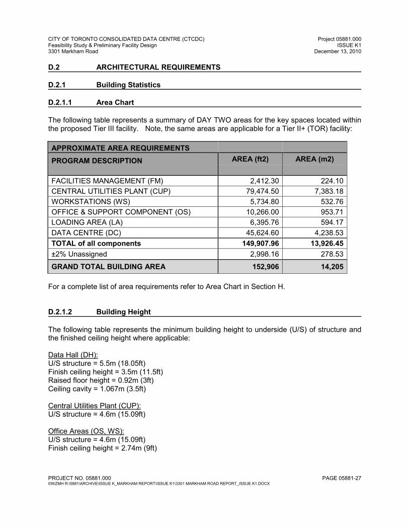
D.2 ARCHITECTURAL REQUIREMENTS D.2.1 Building Statistics D.2.1.1 Area Chart The following table represents a summary of DAY TWO areas for the key spaces located within the proposed Tier III facility. Note, the same areas are applicable for a Tier II+ (TOR) facility:
APPROXIMATE AREA REQUIREMENTS
PROGRAM DESCRIPTION AREA (ft2) AREA (m2)
FACILITIES MANAGEMENT (FM) 2,412.30 224.10
CENTRAL UTILITIES PLANT (CUP) 79,474.50 7,383.18
WORKSTATIONS (WS) 5,734.80 532.76
OFFICE & SUPPORT COMPONENT (OS) 10,266.00 953.71
LOADING AREA (LA) 6,395.76 594.17
DATA CENTRE (DC) 45,624.60 4,238.53
TOTAL of all components 149,907.96 13,926.45
±2% Unassigned 2,998.16 278.53
GRAND TOTAL BUILDING AREA 152,906 14,205
For a complete list of area requirements refer to Area Chart in Section H. D.2.1.2 Building Height The following table represents the minimum building height to underside (U/S) of structure and the finished ceiling height where applicable: Data Hall (DH): U/S structure = 5.5m (18.05ft) Finish ceiling height = 3.5m (11.5ft) Raised floor height = 0.92m (3ft) Ceiling cavity = 1.067m (3.5ft) Central Utilities Plant (CUP): U/S structure = 4.6m (15.09ft) Office Areas (OS, WS): U/S structure = 4.6m (15.09ft) Finish ceiling height = 2.74m (9ft)
CITY OF TORONTO CONSOLIDATED DATA CENTRE (CTCDC) Project 05881.000 Feasibility Study & Preliminary Facility Design ISSUE K1 3301 Markham Road December 13, 2010
PROJECT NO. 05881.000 PAGE 05881-28 ©WZMH R:\5881\ARCHIVE\ISSUE K_MARKHAM REPORT\ISSUE K1\3301 MARKHAM ROAD REPORT_ISSUE K1.DOCX
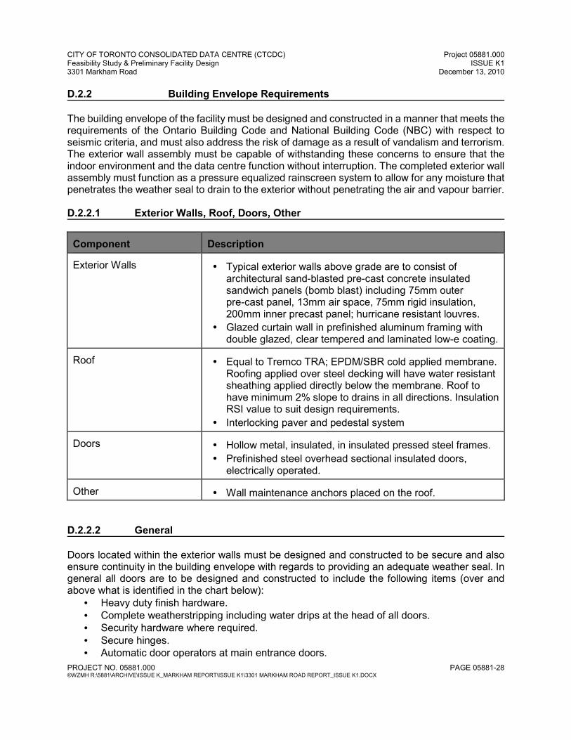
D.2.2 Building Envelope Requirements The building envelope of the facility must be designed and constructed in a manner that meets the requirements of the Ontario Building Code and National Building Code (NBC) with respect to seismic criteria, and must also address the risk of damage as a result of vandalism and terrorism. The exterior wall assembly must be capable of withstanding these concerns to ensure that the indoor environment and the data centre function without interruption. The completed exterior wall assembly must function as a pressure equalized rainscreen system to allow for any moisture that penetrates the weather seal to drain to the exterior without penetrating the air and vapour barrier. D.2.2.1 Exterior Walls, Roof, Doors, Other
Component
Description
Exterior Walls
• Typical exterior walls above grade are to consist of
architectural sand-blasted pre-cast concrete insulated sandwich panels (bomb blast) including 75mm outer pre-cast panel, 13mm air space, 75mm rigid insulation, 200mm inner precast panel; hurricane resistant louvres.
• Glazed curtain wall in prefinished aluminum framing with double glazed, clear tempered and laminated low-e coating.
Roof
• Equal to Tremco TRA; EPDM/SBR cold applied membrane.
Roofing applied over steel decking will have water resistant sheathing applied directly below the membrane. Roof to have minimum 2% slope to drains in all directions. Insulation RSI value to suit design requirements.
• Interlocking paver and pedestal system Doors
• Hollow metal, insulated, in insulated pressed steel frames. • Prefinished steel overhead sectional insulated doors,
electrically operated. Other
• Wall maintenance anchors placed on the roof.
D.2.2.2 General Doors located within the exterior walls must be designed and constructed to be secure and also ensure continuity in the building envelope with regards to providing an adequate weather seal. In general all doors are to be designed and constructed to include the following items (over and above what is identified in the chart below):
• Heavy duty finish hardware. • Complete weatherstripping including water drips at the head of all doors. • Security hardware where required. • Secure hinges. • Automatic door operators at main entrance doors.
CITY OF TORONTO CONSOLIDATED DATA CENTRE (CTCDC) Project 05881.000 Feasibility Study & Preliminary Facility Design ISSUE K1 3301 Markham Road December 13, 2010
PROJECT NO. 05881.000 PAGE 05881-29 ©WZMH R:\5881\ARCHIVE\ISSUE K_MARKHAM REPORT\ISSUE K1\3301 MARKHAM ROAD REPORT_ISSUE K1.DOCX
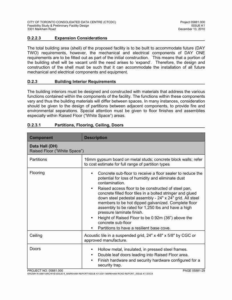
D.2.2.3 Expansion Considerations The total building area (shell) of the proposed facility is to be built to accommodate future (DAY TWO) requirements, however, the mechanical and electrical components of DAY ONE requirements are to be fitted out as part of the initial construction. This means that a portion of the building shell will be vacant until the need arises to ‘expand’. Therefore, the design and construction of the shell must be such that it can accommodate the installation of all future mechanical and electrical components and equipment. D.2.3 Building Interior Requirements The building interiors must be designed and constructed with materials that address the various functions contained within the components of the facility. The functions within these components vary and thus the building materials will differ between spaces. In many instances, consideration should be given to the design of partitions between adjacent components, to provide fire and environmental separations. Special attention must be given to floor finishes and assemblies especially within Raised Floor (“White Space”) areas. D.2.3.1 Partitions, Flooring, Ceiling, Doors Component
Description
Data Hall (DH) Raised Floor (“White Space”) Partitions
16mm gypsum board on metal studs; concrete block walls; refer to cost estimate for full range of partition types
Flooring
• Concrete sub-floor to receive a floor sealer to reduce the
potential for loss of humidity and eliminate dust contamination.
• Raised access floor to be constructed of steel pan, concrete filled floor tiles in a bolted stringer and glued down steel pedestal assembly - 24" x 24" grid. All steel members to be hot dipped galvanized. Complete floor assembly to be rated for 1,250 lbs and have a high pressure laminate finish.
• Height of Raised Floor to be 0.92m (36”) above the concrete sub-floor
• Partitions to have a resilient base cove. Ceiling
Acoustic tile in a suspended grid, 24" x 48" x 5/8" by CGC or approved manufacture.
Doors
• Hollow metal, insulated, in pressed steel frames. • Double leaf doors leading into Raised Floor area. • Finish hardware and security hardware configured for a
security trap.
CITY OF TORONTO CONSOLIDATED DATA CENTRE (CTCDC) Project 05881.000 Feasibility Study & Preliminary Facility Design ISSUE K1 3301 Markham Road December 13, 2010
PROJECT NO. 05881.000 PAGE 05881-30 ©WZMH R:\5881\ARCHIVE\ISSUE K_MARKHAM REPORT\ISSUE K1\3301 MARKHAM ROAD REPORT_ISSUE K1.DOCX
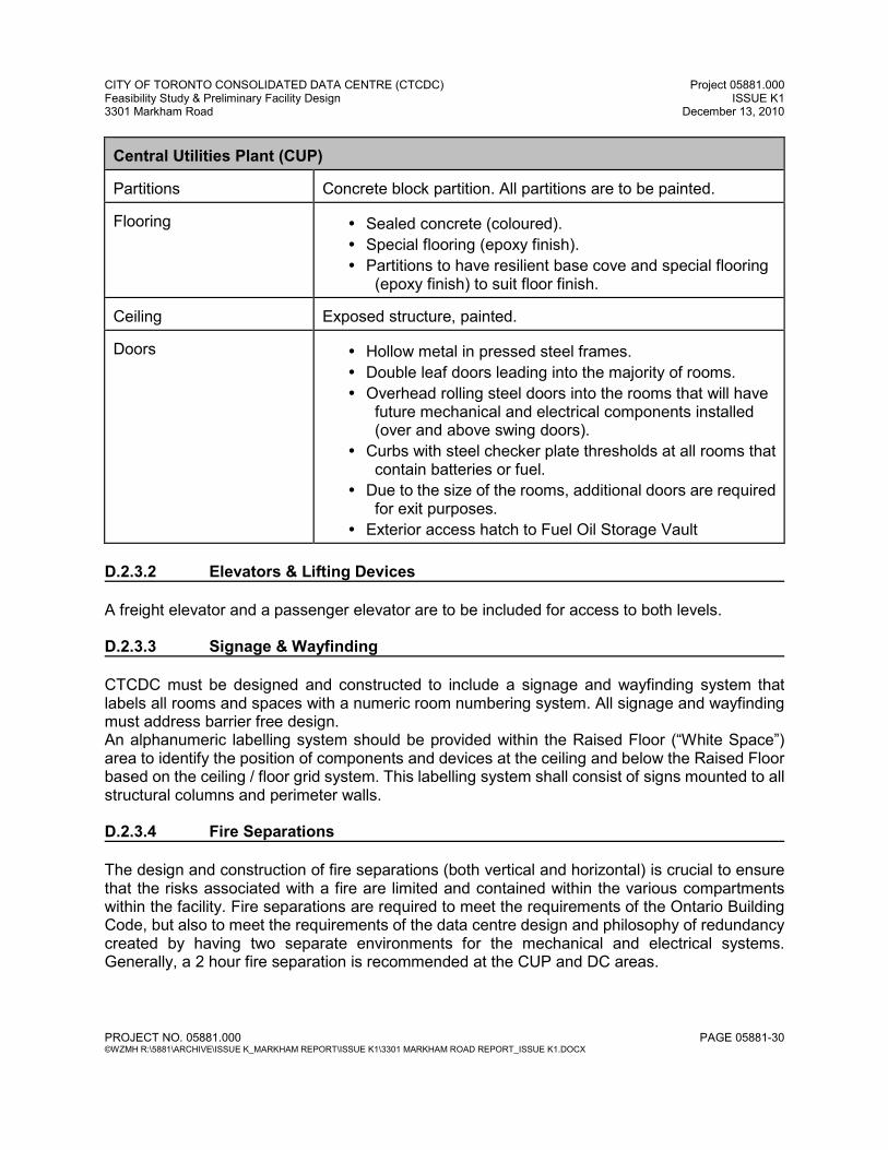
Central Utilities Plant (CUP) Partitions
Concrete block partition. All partitions are to be painted.
Flooring
• Sealed concrete (coloured). • Special flooring (epoxy finish). • Partitions to have resilient base cove and special flooring
(epoxy finish) to suit floor finish. Ceiling
Exposed structure, painted.
Doors
• Hollow metal in pressed steel frames. • Double leaf doors leading into the majority of rooms. • Overhead rolling steel doors into the rooms that will have
future mechanical and electrical components installed (over and above swing doors).
• Curbs with steel checker plate thresholds at all rooms that contain batteries or fuel.
• Due to the size of the rooms, additional doors are required for exit purposes.
• Exterior access hatch to Fuel Oil Storage Vault D.2.3.2 Elevators & Lifting Devices A freight elevator and a passenger elevator are to be included for access to both levels. D.2.3.3 Signage & Wayfinding CTCDC must be designed and constructed to include a signage and wayfinding system that labels all rooms and spaces with a numeric room numbering system. All signage and wayfinding must address barrier free design. An alphanumeric labelling system should be provided within the Raised Floor (“White Space”) area to identify the position of components and devices at the ceiling and below the Raised Floor based on the ceiling / floor grid system. This labelling system shall consist of signs mounted to all structural columns and perimeter walls. D.2.3.4 Fire Separations The design and construction of fire separations (both vertical and horizontal) is crucial to ensure that the risks associated with a fire are limited and contained within the various compartments within the facility. Fire separations are required to meet the requirements of the Ontario Building Code, but also to meet the requirements of the data centre design and philosophy of redundancy created by having two separate environments for the mechanical and electrical systems. Generally, a 2 hour fire separation is recommended at the CUP and DC areas.
CITY OF TORONTO CONSOLIDATED DATA CENTRE (CTCDC) Project 05881.000 Feasibility Study & Preliminary Facility Design ISSUE K1 3301 Markham Road December 13, 2010
PROJECT NO. 05881.000 PAGE 05881-31 ©WZMH R:\5881\ARCHIVE\ISSUE K_MARKHAM REPORT\ISSUE K1\3301 MARKHAM ROAD REPORT_ISSUE K1.DOCX
D.2.3.5 General Doors located within the facility must be designed and constructed to be secure and when located in a fire separation be Underwriters’ Laboratories of Canada (ULC) approved. In general all doors are to be designed and constructed to include the following:
• Heavy duty finish hardware.
• Security hardware where required.
• Secure hinges where required.
• Bumper guards and kick plates within the path of travel of all equipment deliveries.
• Automatic door operators at all doors within the path of travel of all equipment deliveries.
• Automatic door operators at main entrance doors.
• All swing doors shall be a minimum of 3'-0" x 7'-0" unless otherwise noted. All swing doors within the path of travel of all equipment deliveries including entry into the processing area are to be a minimum of 8' -0" high. All swing doors located within a path of travel for the maintenance / installation / removal of mechanical / electrical equipment shall be a minimum of 2 x 3'-6" x 8'-0".
D.2.3.6 Raised Access Floor The raised access floor design and construction is crucial to the successful operations of the facility, in particular within the “White Space”. The recommended minimum height of the raised access floor is 0.92m (36”). The following items should be addressed in the design and construction of the raised access floor:
• Every fourth Raised Floor pedestal is to be grounded.
• All cut outs within the raised access floor tiles are to be trimmed.
• All openings within the raised access floor tiles should be minimized to reduce the potential for air loss from within the raised access floor cavity. All hole penetrations for cabling are to be sealed with brushes to reduce the amount of air leakage.
• Detailed drawings of all components within the raised access floor cavity (including the cabling) should be coordinated and detailed well in advance of construction to ensure that all items fit and air dams are prevented.
D.2.3.7 Expansion Considerations The total building area (shell) of the proposed facility is to be built to accommodate future (DAY TWO) requirements, however, the mechanical and electrical components of DAY ONE requirements are to be fitted out as part of the initial construction. This means that a portion of the building shell will be vacant until the need arises to ‘expand’. Therefore, the design and construction of the shell must be such that it can accommodate the installation of all future mechanical and electrical components and equipment.
CITY OF TORONTO CONSOLIDATED DATA CENTRE (CTCDC) Project 05881.000 Feasibility Study & Preliminary Facility Design ISSUE K1 3301 Markham Road December 13, 2010
PROJECT NO. 05881.000 PAGE 05881-32 ©WZMH R:\5881\ARCHIVE\ISSUE K_MARKHAM REPORT\ISSUE K1\3301 MARKHAM ROAD REPORT_ISSUE K1.DOCX
D.3 STRUCTURAL REQUIREMENTS D.3.1 Introduction D.3.1.1 Project Description The City of Toronto Consolidated Data Centre for Option 1A (formerly known as T3-20A) is mainly a two storey facility above grade (low rise development), with exception of the roof on the west side which is maintained at Level 2. There will be no underground parking garage below the proposed development and surface parking is proposed.
As a general rule for the structural system, concrete structure below grade and steel frame structure above the Ground Floor Level is proposed.
It is our recommendation that entire facility is structurally separated (expansion joint) into two buildings:
• “White Space” including mechanical corridors • “Rest” of facility”
The proposed expansion joint, extending from the roof to the foundation system, could also serve as a noise and vibration separation between CUP Generator Rooms and White Space. D.3.1.2 General Criteria and Assumptions Structural Assumptions: All design and construction to conform to the requirements of the Ontario Building Code, 2006 Edition. Design Criteria:
Entire facility is designed as building of normal importance in accordance OBC 2006.
Requirements for post-disaster building, in accordance with OBC 2006, is evaluated and separate prices for upgrade pertaining to structural, architectural, M&E and IT are indicated.
For wind load, the structure and building envelope recommendations of the OBC 2006 are incorporated, with separate prices indicated for upgrade pertaining to F2 Tornado wind load pressure.
In regards to “bomb blast” scenarios, “Security Risk Assessment” and level of protection, a separate assessment and analysis is performed by a Specialized Consultant and recommendations are beyond structural scope of work and consulting services are indicated.
CITY OF TORONTO CONSOLIDATED DATA CENTRE (CTCDC) Project 05881.000 Feasibility Study & Preliminary Facility Design ISSUE K1 3301 Markham Road December 13, 2010
PROJECT NO. 05881.000 PAGE 05881-33 ©WZMH R:\5881\ARCHIVE\ISSUE K_MARKHAM REPORT\ISSUE K1\3301 MARKHAM ROAD REPORT_ISSUE K1.DOCX
Soil Information: During previous assessment phase for the new Consolidated Data Centre, preliminary Geotechnical Investigation was done by Alston Associates Inc. (Report Ref. No. 08-230, dated November 20, 2008) – this assessment considers a limited number of shallow bore holes on the site. For the design phase of this project, we would recommend that a comprehensive Geotechnical Investigation be done in the near future in order to minimize risk exposure associated with the variations of the soil conditions and affects on the structural cost. Fire Ratings:
The structure is designed for a 2-hour fire rating. It is anticipated that only steel framing will need to be fire proofed without fireproofing of the underside of steel deck. Fire proofing would be required for the second level. D.3.2 Foundations As referenced above, preliminary Geotechnical Investigation Report indicates the following:
• Expected long-term groundwater table is 5.5 m below the present grade, with possibility that it could be at much higher level, depending on the seasonal fluctuation.
• Soil bearing capacity at elevation 1.2 m to 1.5 m below the grade is 200kPa (SLS)
and 300kPa (ULS). Structural Recommendations: Based on the above indicated information and an indication that the basement structure will not be introduced, we would recommend the use of conventional spread footings. For conventional spread footings, it is expected that the founding elevation would be at min. 1.2 m below the grade (frost depth). It should be noted that relatively smaller soil bearing capacity at this elevation of 200kPa (SLS) would govern the size and reinforcement of the footings. A cost benefit is found in minimizing excavation and maximizing simplicity of the construction of the continuous grade beams along the building perimeter.
D.3.3 Slab-On-Grade Structural Recommendations: CUP: Slab-on-grade (SOG) in the Central Utility Plant areas (CUP), exposed to the heavy equipment, will be of conventional construction with 8" thick concrete slab with nominal reinforcement to prevent cracks and long-term maintenance issues. Below heavy equipment and generators, house-keeping pads are anticipated above the SOG. The slab will be supported by min. 10" of compacted Granular A or B material compacted to min.
CITY OF TORONTO CONSOLIDATED DATA CENTRE (CTCDC) Project 05881.000 Feasibility Study & Preliminary Facility Design ISSUE K1 3301 Markham Road December 13, 2010
PROJECT NO. 05881.000 PAGE 05881-34 ©WZMH R:\5881\ARCHIVE\ISSUE K_MARKHAM REPORT\ISSUE K1\3301 MARKHAM ROAD REPORT_ISSUE K1.DOCX
100% Standard Proctor Dry Density. For the floors where epoxy floor finishes are expected, the vapour barrier below slabs is anticipated to mitigate moisture diffusion through the concrete slab, and concrete curing procedure need to be implemented to alleviate possibility of the “curling”. The slab will be saw-cut at a maximum 14' 6" centres throughout.
“OS+WS”: Slab-on-grade (SOG) in the Office Support (OS)and Workstations area (WS), will be of conventional construction with a 6" thick concrete slab with adequate reinforcement to prevent cracks and long-term maintenance issues. The slab will be supported by min. 12" of compacted clear stone Granular A or B material compacted to min. 100% Standard Proctor Dry Density. The slab will be saw-cut at a maximum 14'-6" centres throughout. For the floors where epoxy floor finishes are expected, the vapour barrier below slabs is anticipated to mitigate moisture diffusion through the concrete slab, and concrete curing procedure need to be implemented to alleviate possibility of the “curling”. D.3.4 Second Floor Structural System Structural Recommendations:
• Structural steel framing is more adaptable than a concrete framed building where modifications are carried in the future to accommodate changing requirements.
• The floor structure will consist of concrete on composite metal deck on steel beams supported by steel girders and columns. Assumed structural grid for all Options is 30’x40’. In the East-West direction spacing of the columns is 30’ and in the North –South direction 40’. The floor framing will be designed as composite construction with shear studs used to achieve composite action between the steel beams, deck and concrete. Additional steel beams would be required directly below the concentrated loads of the heavy equipment in the CUPs area. The thickness of concrete on composite metal deck will varies according to the floor loads and to achieve 2 hour fire rating without fire-spraying underside of the deck.
• The concrete will have a minimum 4000 psi (25 MPa) compressive strength at 28 days, and will be reinforced with welded wire mesh (WWM) generally and reinforcing steel over beams and girders.
D.3.5 Roof Structural System Structural Recommendations: Roof over CUP:
• Main roof structure for the CUP building will consist of metal deck on steel beams
supported by steel girders and columns which should be designed for the snow load and suspended M&E services below the roof.
• For CUP areas, where the heavy mechanical equipment could be expected above the roof, galvanized horizontal steel frame without deck – “steel skeleton” is
CITY OF TORONTO CONSOLIDATED DATA CENTRE (CTCDC) Project 05881.000 Feasibility Study & Preliminary Facility Design ISSUE K1 3301 Markham Road December 13, 2010
PROJECT NO. 05881.000 PAGE 05881-35 ©WZMH R:\5881\ARCHIVE\ISSUE K_MARKHAM REPORT\ISSUE K1\3301 MARKHAM ROAD REPORT_ISSUE K1.DOCX
anticipated above the main roof structure. Vertical posts for the “steel skeleton” above the roof will be supported on the main building columns. Horizontal steel skeleton above the roof will accommodate flexibility for the future equipment changes without interruption of the services in the CUP.
• Anticipated screens for the M&E equipment above the roof will be achieved by galvanized steel structure and knee-bracings.
Roof over “WHITE SPACE”:
• Above the “WHITE SPACE” it is not anticipated that the roof structure will support heavy mechanical equipment. The roof structure here will consist of metal deck on steel beams supported by steel girders and columns designed for the snow load and any suspended light equipment such as air handling units.
D.3.6 Diesel Fuel Storage D.3.6.1 Concrete structure For the below grade “Diesel Fuel Storage” a cast-in-place concrete “vault” structure is anticipated. Currently, the proposed location of the underground “vault“, adjacent to the north side of the building will have an affect on the founding elevation of the building columns in order to avoid underpinning. It is also anticipated that a temporary shoring system will be required during excavation due to proximity to the edge of the property line. Roof over the “vault” is designed for the heavy traffic load (highway requirements). D.3.7 Design Analysis D.3.7.1 Superimposed Loads The design loads for the projects will follow either minimum OBC 2006 requirements or appropriate weight of the M&E and IT equipment and associated services (more stringent governing). At this point of the project development, the following superimposed design loads have been assumed: CUP - Recommended Vertical Loading:
Ground Floor: Live Load ……………………….. equipment - concentrated loads
Super Imposed Dead Load Pads…………………………… 50 psf (2.50 kPa) Block wall partitions……………. ---- psf (-------kPa)
Second Floor: Live Load (min)………………… 200 psf (10.00 kPa)
Super Imposed Dead Load Pads …………………………… 50 psf (2.50 kPa) Suspended M&E………………. 70 psf (3.50 kPa) Block wall partitions ……………-----psf (--- kPa)
CITY OF TORONTO CONSOLIDATED DATA CENTRE (CTCDC) Project 05881.000 Feasibility Study & Preliminary Facility Design ISSUE K1 3301 Markham Road December 13, 2010
PROJECT NO. 05881.000 PAGE 05881-36 ©WZMH R:\5881\ARCHIVE\ISSUE K_MARKHAM REPORT\ISSUE K1\3301 MARKHAM ROAD REPORT_ISSUE K1.DOCX
Roof: Snow & Rain Loading…………….”normal importance building” – OBC 2006 Super Imposed Dead Load Roof Ballast or Pavers…………….50 psf (2.50 kPa) Roofing …………………………….. 5 psf (0.25 kPa ) Suspended M&E…………………..70 psf (3.50 kPa ) Mechanical Platform (“steel skeleton”): Live Load ……………………… equipment - concentrated loads “WHITE SPACE” - Recommended Vertical Loading:
Second Floor: Live Load (min)……………………... 200 psf (10.00 kPa)
Super Imposed Dead Load Raised Flooring + suspended M&E…50 psf (2.50 kPa) Light weight partitions…………………20 psf (1.00 kPa)
Roof: Snow & Rain Loading ……………….“normal importance building” – OBC 2006
Super Imposed Dead Load Roof Ballast or Pavers ……………….50 psf (2.50 kPa) Roofing ………………………………….5 psf (0.25 kPa) Suspended M&E………………………30 psf (1.50 kPa)
“OFFICE SUPPORT” - Recommended Vertical Loading:
Ground Floor: Live Load (min)………………………..50 psf (2.50 kPa)
Super Imposed Dead Load Raised Flooring + suspended M&E….50 psf (2.50 kPa) Light weight partitions…………………20 psf (1.00 kPa)
Roof: Snow & Rain Loading ………………..“normal importance building” – OBC 2006
Super Imposed Dead Load Roof Ballast or Pavers…………………50 psf (2.50 kPa) Roofing …………………………………..5 psf (0.25 kPa) Suspended M&E……………………….30 psf (1.50 kPa)
D.3.7.2 Wind Load Summary All wind loads in accordance with requirements of OBC 2006 for normal importance buildings.
CITY OF TORONTO CONSOLIDATED DATA CENTRE (CTCDC) Project 05881.000 Feasibility Study & Preliminary Facility Design ISSUE K1 3301 Markham Road December 13, 2010
PROJECT NO. 05881.000 PAGE 05881-37 ©WZMH R:\5881\ARCHIVE\ISSUE K_MARKHAM REPORT\ISSUE K1\3301 MARKHAM ROAD REPORT_ISSUE K1.DOCX
D.3.7.3 Seismic Load Summary All seismic loads are to be in accordance with requirements of OBC 2006 for normal importance buildings. D.3.8 Material Specifications D.3.8.1 Concrete Limit States Design and detailing shall be used in accordance with Canadian Standards Association A23.3-04 - “Design of Concrete Structures” and also in accordance with CSA A23.1/A23.2-04 - “Concrete Materials and Methods of Concrete Construction/Methods of Testing for Concrete”.
Concrete Strength: Location: Strength: Interior Slabs 4000 psi (25 MPa) Spread footing 5000 psi (35 MPa) Grade Beams 5000 psi (35 Mpa) Concrete on Deck 4000 psi (25 MPa)
D.3.8.2 Reinforcing Steel All reinforcement to conform the requirements of ASTM A615 Series Fy= 60 ksi (400 MPa)
Diameter Size: 10M to 30M D.3.8.3 Structural Steel In general, details and design of structural steel shall be in accordance with the Canadian Standards Association CAN/CSA S16-01 “Limit States Design of Steel Structures”.
Steel elements: All wide flange, welded wide flange shapes: CAN/CSA G40.21 Grade 350W All hollow structural sections: ASTM A500 Grade C. All channels, Angles, Plates: CAN/CSA G40.21 Grade 300W. All high strength bolts, nuts and washers: ASTM A325.
Steel deck: All steel deck to conform the requirements of ASTM A653M Grade A or B.
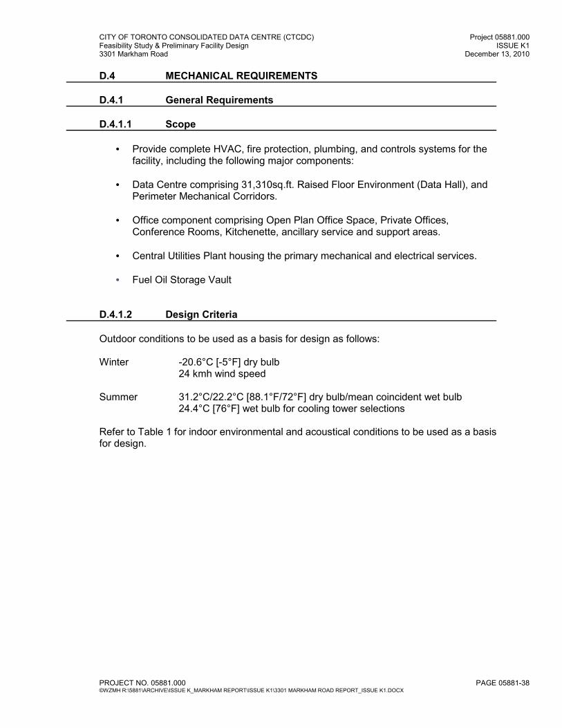
CITY OF TORONTO CONSOLIDATED DATA CENTRE (CTCDC) Project 05881.000 Feasibility Study & Preliminary Facility Design ISSUE K1 3301 Markham Road December 13, 2010
PROJECT NO. 05881.000 PAGE 05881-38 ©WZMH R:\5881\ARCHIVE\ISSUE K_MARKHAM REPORT\ISSUE K1\3301 MARKHAM ROAD REPORT_ISSUE K1.DOCX
D.4 MECHANICAL REQUIREMENTS D.4.1 General Requirements D.4.1.1 Scope
• Provide complete HVAC, fire protection, plumbing, and controls systems for the facility, including the following major components:
• Data Centre comprising 31,310sq.ft. Raised Floor Environment (Data Hall), and Perimeter Mechanical Corridors.
• Office component comprising Open Plan Office Space, Private Offices, Conference Rooms, Kitchenette, ancillary service and support areas.
• Central Utilities Plant housing the primary mechanical and electrical services.
• Fuel Oil Storage Vault
D.4.1.2 Design Criteria Outdoor conditions to be used as a basis for design as follows: Winter -20.6°C [-5°F] dry bulb
24 kmh wind speed Summer 31.2°C/22.2°C [88.1°F/72°F] dry bulb/mean coincident wet bulb
24.4°C [76°F] wet bulb for cooling tower selections
Refer to Table 1 for indoor environmental and acoustical conditions to be used as a basis for design.
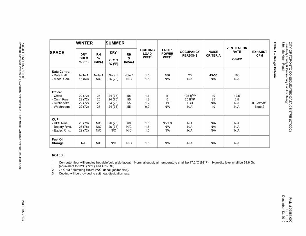
CITY OF TORONTO CONSOLIDATED DATA CENTRE (C
TCDC)
Project 05881.000
Feasibility S
tudy &
Prelim
inary F
acility D
esign
ISSUE K1
3301 Markham Road
December 1
3, 2010
PROJE
CT NO. 0
5881.000
PAGE 05881-39
©WZMH R:\5
881\ARCHIVE\IS
SUE K_MARKHAM REPORT\IS
SUE K1\3301 MARKHAM ROAD REPORT_ISSUE K1.DOCX
Table 1 – Design Crite
ria
EXHAUST
CFM
0.3 cfm/ft2 Note 2
NOTES: 1. Computer floor will employ hot aisle/cold aisle layout. Nominal supply air temperature shall be 17.2°C (63°F). Humidity level shall be 54.6 Gr.
(equivalent to 22°C (72°F) and 45% RH). 2. 75 CFM / plumbing fixture (WC, urinal, janitor sink). 3. Cooling will be provided to suit heat dissipation rate.
VENTILATION
RATE
CFM/P
100 N/A
12.5 6.5 N/A N/A
N/A N/A N/A
N/A
NOISE
CRITERIA
45-50 N/A
40 35 N/A 40
N/A N/A N/A
N/A
OCCUPANCY
PERSONS
20 N/A
125 ft2/P 25 ft2/P TBD N/A
N/A N/A N/A
N/A
EQUIP. POWER
W/FT2
186 N/A
5 5
TBD N/A
Note 3 N/A N/A
N/A
LIGHTING LOAD
W/FT2
1.5 1.5
1.1 1.3 1.2 0.9
1.5 1.5 1.5
1.5
SUMMER
RH
%
(MAX.)
Note 1 N/C
55 55 55 55
60 N/C N/C
N/C
DRY
BULB
°C (°F)
Note 1 26 (78)
24 (75) 24 (75) 24 (75) 24 (75)
26 (78) 26 (78) N/C
N/C
WINTER
RH
%
(MIN.)
Note 1 N/C
25 25 25 25
N/C N/C N/C
N/C
DRY
BULB
°C (°F)
Note 1 16 (60)
22 (72) 22 (72) 22 (72) 22 (72)
26 (78) 26 (78) 22 (72)
N/C
SPACE
Data Centre:
- Data Hall - Mech. Corr.
Office: - Office - Conf. Rms. - Kitchenette - Washrooms
CUP: - UPS Rms. - Battery Rms. - Equip. Rms.
Fuel Oil
Storage
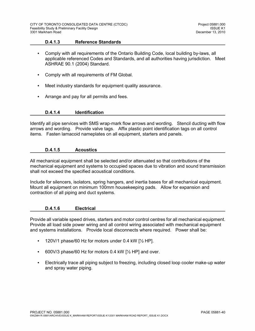
CITY OF TORONTO CONSOLIDATED DATA CENTRE (CTCDC) Project 05881.000 Feasibility Study & Preliminary Facility Design ISSUE K1 3301 Markham Road December 13, 2010
PROJECT NO. 05881.000 PAGE 05881-40 ©WZMH R:\5881\ARCHIVE\ISSUE K_MARKHAM REPORT\ISSUE K1\3301 MARKHAM ROAD REPORT_ISSUE K1.DOCX
D.4.1.3 Reference Standards
• Comply with all requirements of the Ontario Building Code, local building by-laws, all applicable referenced Codes and Standards, and all authorities having jurisdiction. Meet ASHRAE 90.1 (2004) Standard.
• Comply with all requirements of FM Global.
• Meet industry standards for equipment quality assurance.
• Arrange and pay for all permits and fees.
D.4.1.4 Identification Identify all pipe services with SMS wrap-mark flow arrows and wording. Stencil ducting with flow arrows and wording. Provide valve tags. Affix plastic point identification tags on all control items. Fasten lamacoid nameplates on all equipment, starters and panels. D.4.1.5 Acoustics All mechanical equipment shall be selected and/or attenuated so that contributions of the mechanical equipment and systems to occupied spaces due to vibration and sound transmission shall not exceed the specified acoustical conditions. Include for silencers, isolators, spring hangers, and inertia bases for all mechanical equipment. Mount all equipment on minimum 100mm housekeeping pads. Allow for expansion and contraction of all piping and duct systems. D.4.1.6 Electrical Provide all variable speed drives, starters and motor control centres for all mechanical equipment. Provide all load side power wiring and all control wiring associated with mechanical equipment and systems installations. Provide local disconnects where required. Power shall be:
• 120V/1 phase/60 Hz for motors under 0.4 kW [½ HP].
• 600V/3 phase/60 Hz for motors 0.4 kW [½ HP] and over.
• Electrically trace all piping subject to freezing, including closed loop cooler make-up water and spray water piping.
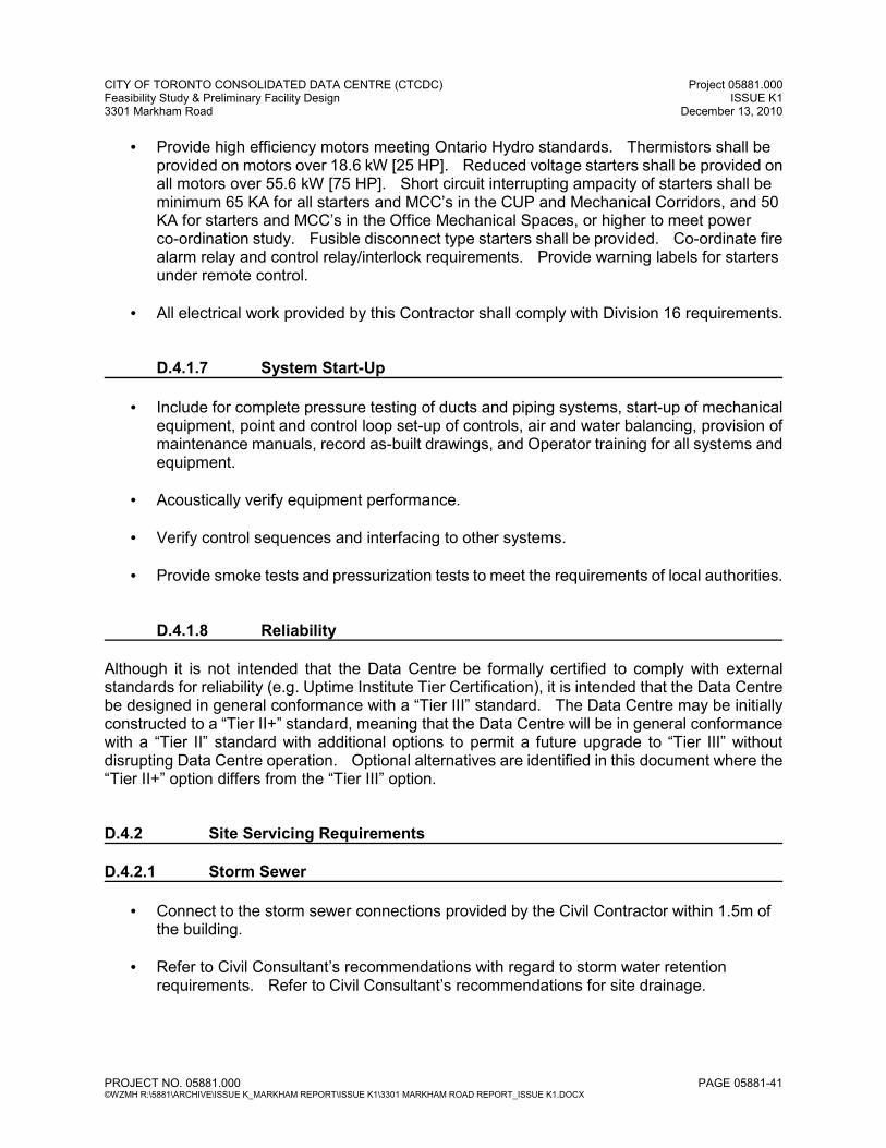
CITY OF TORONTO CONSOLIDATED DATA CENTRE (CTCDC) Project 05881.000 Feasibility Study & Preliminary Facility Design ISSUE K1 3301 Markham Road December 13, 2010
PROJECT NO. 05881.000 PAGE 05881-41 ©WZMH R:\5881\ARCHIVE\ISSUE K_MARKHAM REPORT\ISSUE K1\3301 MARKHAM ROAD REPORT_ISSUE K1.DOCX
• Provide high efficiency motors meeting Ontario Hydro standards. Thermistors shall be provided on motors over 18.6 kW [25 HP]. Reduced voltage starters shall be provided on all motors over 55.6 kW [75 HP]. Short circuit interrupting ampacity of starters shall be minimum 65 KA for all starters and MCC’s in the CUP and Mechanical Corridors, and 50 KA for starters and MCC’s in the Office Mechanical Spaces, or higher to meet power co-ordination study. Fusible disconnect type starters shall be provided. Co-ordinate fire alarm relay and control relay/interlock requirements. Provide warning labels for starters under remote control.
• All electrical work provided by this Contractor shall comply with Division 16 requirements.
D.4.1.7 System Start-Up
• Include for complete pressure testing of ducts and piping systems, start-up of mechanical equipment, point and control loop set-up of controls, air and water balancing, provision of maintenance manuals, record as-built drawings, and Operator training for all systems and equipment.
• Acoustically verify equipment performance.
• Verify control sequences and interfacing to other systems.
• Provide smoke tests and pressurization tests to meet the requirements of local authorities.
D.4.1.8 Reliability Although it is not intended that the Data Centre be formally certified to comply with external standards for reliability (e.g. Uptime Institute Tier Certification), it is intended that the Data Centre be designed in general conformance with a “Tier III” standard. The Data Centre may be initially constructed to a “Tier II+” standard, meaning that the Data Centre will be in general conformance with a “Tier II” standard with additional options to permit a future upgrade to “Tier III” without disrupting Data Centre operation. Optional alternatives are identified in this document where the “Tier II+” option differs from the “Tier III” option. D.4.2 Site Servicing Requirements D.4.2.1 Storm Sewer
• Connect to the storm sewer connections provided by the Civil Contractor within 1.5m of the building.
• Refer to Civil Consultant’s recommendations with regard to storm water retention requirements. Refer to Civil Consultant’s recommendations for site drainage.
CITY OF TORONTO CONSOLIDATED DATA CENTRE (CTCDC) Project 05881.000 Feasibility Study & Preliminary Facility Design ISSUE K1 3301 Markham Road December 13, 2010
PROJECT NO. 05881.000 PAGE 05881-42 ©WZMH R:\5881\ARCHIVE\ISSUE K_MARKHAM REPORT\ISSUE K1\3301 MARKHAM ROAD REPORT_ISSUE K1.DOCX
D.4.2.2 Sanitary Sewer Connect to the sanitary sewer connections provided by the Civil Contractor within 1.5m of the building. D.4.2.3 Water Service Connect to the two (2) 200mm [8”] fire mains provided from the municipal street main by the Civil Contractor within 1.5m of the building. D.4.2.4 Natural Gas Arrange for the local Gas Utility to provide service to the site and extend the gas line from the meter to serve the building. D.4.3 Plumbing and Drainage Systems D.4.3.1 Design Criteria Plumbing systems, including domestic cold and hot water, sanitary and storm drainage, shall be designed to accommodate diversified design flow of connected fixtures. Materials and equipment shall be selected to give a minimum system life expectancy of 50 years, based upon soil analysis for underground lines and in water quality anticipated in all lines. D.4.3.2 Storm Drainage System
• Provide a complete storm water drainage system to drain each roof and air well; minimum two (2) drains per surface except for small air wells. Provide cleanouts in mains. Size system to handle runoff from a 100 year recurrence storm or to local Code requirement, whichever is greater.
• Provide drainage for sub-slab drainage (sub-slab drainage system to be by others), including: Main Building. System shall include settling basin.
• Provide storm sump pits and pumps to lift effluent that cannot be run by gravity.
o All sump pumps shall be of the duplex pumped type, powered from two (2) power sources.
o Provide water sensor alarm to the BAS for elevator sumps.
• Connection of sump discharge pipe shall be made in such a way as to avoid back-up into the building.
CITY OF TORONTO CONSOLIDATED DATA CENTRE (CTCDC) Project 05881.000 Feasibility Study & Preliminary Facility Design ISSUE K1 3301 Markham Road December 13, 2010
PROJECT NO. 05881.000 PAGE 05881-43 ©WZMH R:\5881\ARCHIVE\ISSUE K_MARKHAM REPORT\ISSUE K1\3301 MARKHAM ROAD REPORT_ISSUE K1.DOCX
D.4.3.3 Sanitary Drainage System
• Provide a complete sanitary drainage system, including waste and vent connections to each plumbing fixture, as well as primed and vented floor drainage throughout.
• Drainage and vent piping within the facility shall be DWV copper under 65mm [2½”]; CSA Class 4000 cast iron for 75mm [3”] and over. Approved plastic piping can be considered for underground services. Provide sewer cleanouts at every change in direction and as required by Code.
• Provide sanitary sump pits and pumps to lift effluent that cannot be run by gravity, including: Fuel Oil Storage Vault.
o All sump pumps shall be of the duplex pumped type, powered from two (2) power sources.
• Connection of sewage pump discharge lines shall be made in such a way as to avoid back-up into the building
• Provide cast iron floor drains. Floor drains shall have “heel-proof” grates. Floor sinks shall be equipped with partial grates in Mechanical Rooms.
• Floor drains to be located in the following areas:
o Floor drains shall be located in all Toilet Rooms, positioned within a toilet cubicle.
o In Mechanical and Electrical Equipment Rooms, including all rooms with curbs. Provide backwater valves in drain lines from Electrical Equipment Rooms.
o Throughout the Fuel Oil Storage Vault.
o In applications with equipment drains.
o Throughout the Raised Floor Area and Mechanical Service Corridor of the Data Centre.
• Floor drains for Battery Storage Rooms shall lead to a sealed and vented sump.
• Provide water sensor alarm to the BAS for elevator sumps.
D.4.3.4 Potable Water Systems (Hot and Cold)
• Piping shall be Type L copper with lead-free joints. Provide ball valves on pipes 65mm [2½”] and smaller.
• Piping shall be arranged to eliminate “dead ends” that could stagnate and contaminate the water system.

CITY OF TORONTO CONSOLIDATED DATA CENTRE (CTCDC) Project 05881.000 Feasibility Study & Preliminary Facility Design ISSUE K1 3301 Markham Road December 13, 2010
PROJECT NO. 05881.000 PAGE 05881-44 ©WZMH R:\5881\ARCHIVE\ISSUE K_MARKHAM REPORT\ISSUE K1\3301 MARKHAM ROAD REPORT_ISSUE K1.DOCX
• Distribution system shall be zoned by means of shut-off valves to permit repair of piping and/or equipment with minimum effect to the overall operation of the facility. All branches off mains and risers must be valved.
• Piping shall be sized in accordance with the BMS-66 and BMS-79 water pipe sizing tables or the “ASPE Data Book”. Velocities shall not exceed the “ASPE”-recommended values for the specific application.
• Systems shall be sized to handle diversified demands, including the future equipment for the full 20 year design capacity.
• Install exterior non-freeze type hose bibs 45m [150’] O.C. at exterior building, and to suit landscaping requirements.
• Provide non-freeze type hose bibs on roof to meet window washing requirements.
• Provide hose bibs in Garbage Room, Loading Dock, and in Mechanical Rooms.
• Minimum pipe size serving more than one (1) fixture is 20mm [¾”] (i.e., no 12mm [½”]).
• Closed loop cooler make-up lines shall have separate meters.
• Provide quick-fill lines for all heating and cooling systems.
• Provide local electric domestic hot water heaters located in the vicinity of each load (washrooms, kitchenette, etc.).
D.4.3.5 Plumbing Fixtures Plumbing fixtures shall be generally as follows:
WC’s: Flush valve, wall hung syphon jet, open front seat on elongated bowls.
Urinals: Wall hung with side shields, proximity sensor flush valve.
Lavs: Self-rimming counter mounted vitreous china with proximity sensor tempered water.
Janitor’s Sink: Mop sink with wall mounted trim.
Drinking Fountains: Refrigerated barrier free wall hung.
D.4.3.6 Eye Wash Provide wall hung eye wash units equal to Haws Model SHE-2 in all Battery Rooms, Chiller Room, Boiler Room, and where required by Code.
CITY OF TORONTO CONSOLIDATED DATA CENTRE (CTCDC) Project 05881.000 Feasibility Study & Preliminary Facility Design ISSUE K1 3301 Markham Road December 13, 2010
PROJECT NO. 05881.000 PAGE 05881-45 ©WZMH R:\5881\ARCHIVE\ISSUE K_MARKHAM REPORT\ISSUE K1\3301 MARKHAM ROAD REPORT_ISSUE K1.DOCX
D.4.3.7 Diesel Generator Fuel Oil, Exhaust and Cooling Systems
• Provide a complete diesel generator fuel oil storage and distribution system including diesel fuel oil storage vault (buried adjacent to building with access from exterior). Provide 24 hours of continuous supply to the full running capacity of the diesel generators, two (2) horizontal steel above ground storage tanks, two (2) sets of duplex fuel oil transfer pump sets on emergency power to deliver oil through two (2) sets of supply and return mains to the generator day tanks, one (1) 500 I gal day tank for each generator.
• Provide emergency drainage system to accommodate fuel spills and/or sprinkler discharge in the Daytank Rooms comprising floor drains in each room draining to a single buried storage tank.
• Provide a complete diesel generator exhaust system including stacks and muffler system located as per Ontario Ministry of Environment directives.
• Provide a complete ventilation and temperature control system for the generator room. Provide sound attenuation silencers at inlet and discharge.
D.4.4 Fire Protection Systems
• The entire project shall be protected by a combined sprinkler and fire standpipe system. The system shall be hydraulically designed and will be supported by one (1) electrically driven fire pump. Sprinklers shall be wet systems throughout, except dry systems shall be provided for the Loading Dock, the rooms housing the diesel generators, and the Fuel Storage Vault. Sprinkler systems shall be electrically supervised.
• Provide double interlocked pre-action sprinkler systems for the entire Data Hall, Network Operations Centre, Network Communications Room and Data Hall Control Room. Provide a cross-zoned heat detection system to activate this system.
• Provide a CO2 fire suppression system for the entire Raised Floor Area of the Data Centre. Provide a set of reserve CO2 cylinders, complete with all necessary piping and controls, to maintain continuous coverage while one (1) set of cylinders is being refilled or otherwise serviced. System discharge shall be initiated based on smoke detection from the VESDA system. (VESDA system shall be provided by Division 16.)
• Provide fire extinguishers throughout to meet local fire department and OFC requirements.
CITY OF TORONTO CONSOLIDATED DATA CENTRE (CTCDC) Project 05881.000 Feasibility Study & Preliminary Facility Design ISSUE K1 3301 Markham Road December 13, 2010
PROJECT NO. 05881.000 PAGE 05881-46 ©WZMH R:\5881\ARCHIVE\ISSUE K_MARKHAM REPORT\ISSUE K1\3301 MARKHAM ROAD REPORT_ISSUE K1.DOCX
D.4.4.1 Sprinkler Coverage Schedule
AREA
HAZARD
CLASSIFICATION DEMAND/DENSITY
(USgpm/ft2/ft
2)
HOSE STREAM ALLOWANCE
(USgpm)
SPRINKLER TYPE
Office and Support
Light
0.10/1,500
250
Semi-Recessed
CUP
Ordinary Group 2
0.20/3,000
500
Rough Bronze Upright or
Pendant With Escutcheon
Data Centre
Light
0.10/3,000 (Pre-Action)
250
Semi-Recessed
Diesel
Generator Rooms
Extra
Group 1
0.25/4,000
(Dry)
500
Rough Bronze Upright, 286°F (141°C) Heads
D.4.5 Heating and Cooling Plant D.4.5.1 General
• Provide a central heating plant, to provide space heating water to the entire facility.
• Provide a central cooling plant to provide chilled water to the raised floor area and CUP. Office and support areas are cooled via DX rooftop units.
• One redundant piece of equipment will be provided for each type of equipment serving the Data Centre (N+1). Systems shall be designed to permit any individual piece of equipment to be removed from service on a planned basis while the entire Data Centre continues to operating at peak design capacity without interruption. Initial equipment installation shall suit projected day one loads with provision for future installation of additional equipment to support future increased loads (via allocation of space and valved and capped piping connections).
• Two independent chilled water distribution networks shall be provided. The chilled water distribution networks shall be sized for the full projected 20 year design load. Systems shall be designed such that any one element of one distribution network can be removed from service on a planned basis while the entire Data Centre continues to operating at peak design capacity without interruption.
o OPTIONAL: In the event that the Tier II+ option is selected, redundant distribution networks will not be provided. Removal of an element of the distribution network will require shutdown of the Data Centre. Provision shall be made by means of system layout, provision of capped connections and provision of space for future piping installation to permit the installation of a future parallel chilled water distribution network to meet the intent outlined above.
• Arrange piping and valving to optimize sharing equipment.
CITY OF TORONTO CONSOLIDATED DATA CENTRE (CTCDC) Project 05881.000 Feasibility Study & Preliminary Facility Design ISSUE K1 3301 Markham Road December 13, 2010
PROJECT NO. 05881.000 PAGE 05881-47 ©WZMH R:\5881\ARCHIVE\ISSUE K_MARKHAM REPORT\ISSUE K1\3301 MARKHAM ROAD REPORT_ISSUE K1.DOCX
D.4.5.2 Cooling Plant
• Provide two (2) 950 ton centrifugal chillers (one (1) duty and one (1) standby). Provide space and valved and capped connections to permit the addition of two (2) future 950 ton centrifugal chillers as Data Centre loads increase (total of three (3) duty and one (1) standby). Size piping mains to accommodate full future design flow. Chillers shall utilize either refrigerant R-123 or R-134a. Chillers shall be equipped with hot gas bypass. Provide all systems and equipment for the Chiller Room in compliance with CSA B-52. The design entering and leaving chilled water temperatures shall be 18.9°C (66°F) and 10°C (50°F) respectively.
• Provide evaporative closed loop coolers located on the CUP roof for heat rejection. Provide two closed loop coolers for each chiller (total of four (4)). Each closed loop cooler shall have a heat rejection capacity of 475 tons at summer design conditions. All coolers shall be equipped to operate during the Winter, and provided with 40% ethylene glycol. All cooler fans shall be equipped with variable frequency drives (VFD’s) complete with manual bypass. Coolers shall be FM Global certified. Provide valved and capped connections to permit addition of eight (8) future 475 ton closed loop coolers. Provide remote sumps sized to contain sufficient water to permit operation of the closed loop coolers for minimum 12 hours without make-up water at summer design conditions.
• The chilled water system shall be configured as a primary/secondary system. Independent secondary chilled water circuits shall be provided as described above. Provide a single secondary chilled water circuit to serve miscellaneous loads outside of the Data Centre and CUP as noted below.
• All secondary circuits shall be designed to vary chilled water flow in response to actual loads. All secondary pumps shall be equipped with VFD’s complete with manual bypass.
• Provide a chilled water storage system. The system shall comprise two (2) 56,780 L (15,000 USgal.) insulated, pressurized vertical storage tanks, interconnecting piping, valving and controls. The system shall be connected to both distribution networks. Provide space and valved and capped connections for four (4) future 56,780 L (15,000 USgal) storage tanks to accommodate future increases in load.
• Provide for water-side free cooling. System comprises one (1) heat exchanger, isolation valves, and condenser diverting valves. Provide space and valved and capped connections to accommodate two (2) future heat exchangers. Heat exchangers shall have the following performance:
Hot Side
Flow Rate: 89.9 L/s (1,425 USgpm) Inlet Temperature: 18.9°C (66°F) Outlet Temperature: 10°C (50°F) Fluid: Water
CITY OF TORONTO CONSOLIDATED DATA CENTRE (CTCDC) Project 05881.000 Feasibility Study & Preliminary Facility Design ISSUE K1 3301 Markham Road December 13, 2010
PROJECT NO. 05881.000 PAGE 05881-48 ©WZMH R:\5881\ARCHIVE\ISSUE K_MARKHAM REPORT\ISSUE K1\3301 MARKHAM ROAD REPORT_ISSUE K1.DOCX
Cold Side Flow Rate: 161.9 L/s (2,566 USgpm) Inlet Temperature: 7.8°C (46°F) Outlet Temperature: 13.3°C (56°F) Fluid: 40% E.G.
D.4.5.3 Heating Plant
• Provide three (3) 1000 MBH input natural gas-fired condensing boilers, complete with primary circulating pumps and control panel.
• The space heating system shall be configured as a primary/secondary system.
• The secondary circuit shall be designed to vary hot water flow in response to actual loads. All secondary pumps shall be equipped with VFD’s complete with manual bypass.
D.4.6 Heating, Ventilation and Air Conditioning Systems D.4.6.1 Data Centre Data Hall:
• Provide eight (8) recirculating air handling units located in the adjacent Mechanical Corridor. Arrange air handling units to provide space for twelve (12) future units to be installed as the Data Centre load increases. Provide valved and capped chilled water connections for all future air handling units from both distribution networks (two connections per air handling unit). Size distribution networks to support full future design load.
• Each air handling unit shall deliver conditioned air to the underfloor plenum via sheet metal ductwork, and duct return air from the ceiling plenum above the Data Centre floor. Half of the air handling units shall supply air to the raised floor plenum at a point one quarter of the way across the total width of the Data Hall via ductwork in the raised floor plenum. The other half shall supply air to the raised floor plenum at the perimeter of the Data Hall. Units supplying the perimeter of the Data Hall and the centre portion of the Data Hall shall alternate along the length of the Data Hall. All ductwork under the raised floor shall be installed at day one including ductwork for the six (6) of twelve (12) future air handling units that will supply the interior portion of the Data Hall. Ductwork for the future units shall be provided with an isolation damper at the perimeter of the raised floor and then capped within the mechanical corridor. The discharge ductwork under the raised floor shall be sized to fit between the raised floor pedestals and within a height that allows for installation of cabling (allow for six (6) 22”x32” ducts for each air handling unit serving the centre portion of the Data Hall. Manifold supply ductwork within mechanical corridor to connect to air handling unit.
CITY OF TORONTO CONSOLIDATED DATA CENTRE (CTCDC) Project 05881.000 Feasibility Study & Preliminary Facility Design ISSUE K1 3301 Markham Road December 13, 2010
PROJECT NO. 05881.000 PAGE 05881-49 ©WZMH R:\5881\ARCHIVE\ISSUE K_MARKHAM REPORT\ISSUE K1\3301 MARKHAM ROAD REPORT_ISSUE K1.DOCX
• Each air handling unit shall comprise a filter rack, chilled water cooling coil, and variable volume AF centrifugal fan. Provide a variable frequency drive with bypass for each fan.
• Provide motorized isolation dampers (two (2) per air handling unit) on the supply air ductwork to the floor and the return air ductwork from the ceiling to seal the Data Hall in the event of a CO2 discharge. Isolation dampers may also be closed individually to isolate a unit from the Data Hall.
• Each air handling unit shall be sized to sensibly cool 40,000 CFM of air from nominally 31.1°C [88°F] return temperature to 17.2°C [63°F] discharge temperature.
• Provide supply and return air silencers for Data Centre air handling units.
• Provide egg crate return air ceiling grilles throughout the Data Centre.
• Provide CO2 exhaust system for the underfloor volume comprising: two (2) 5,000 CFM exhaust fans drawing air from under the raised floor and discharging it out louvres on the east wall of the east Mechanical Corridor, and two (2) ducted passive intakes complete with control damper and louvre on the west wall of the west Mechanical Corridor.
• Provide smoke exhaust system for Raised Floor Area comprising: two (2) 15,000 CFM exhaust fans drawing air from the ceiling plenum and discharging it out louvres on the west wall of the West Service Corridor, and two (2) ducted passive intakes complete with control damper and louvre on the east wall of the East Service Corridor.
• Provide rough-in for future chilled water cooled equipment on the raised floor. Rough-in shall comprise ten (10) 100mm valved and capped chilled water supply and return connections from each distribution network (total of twenty (20) pairs), and forty (40) 200mm capped sleeves located in the wall demising the underfloor plenum and the Mechanical Service Corridor. Rough-ins shall be spread evenly through the two mechanical corridors, approximately two (2) pairs every forty feet along the length of the Data Hall
Mechanical Service Corridors: Provide 4-pipe horizontal fan coils complete with distribution ductwork for the Mechanical Corridors adjoining the Raised Floor Area. Ventilation: Provide one (1) heat reclaim ventilation air handling unit to deliver and relieve nominally 8,000 CFM of 100% outdoor air throughout the Data Centre, CUP and FM areas. Make-up air units shall comprise variable volume supply and relief fans, DX cooling coil and condensing unit with hot gas bypass, glycol heating coil to support entire heating load (in case of heat reclaim failure), heat wheel (for sensible and latent reclaim), bypass section, filters, electric steam humidifiers, and variable frequency drives for each fan. Duct ventilation air to Data Hall return plenum and throughout the CUP. Provide constant volume boxes for each zone. Provide separate relief air duct network to all ventilation zones.
CITY OF TORONTO CONSOLIDATED DATA CENTRE (CTCDC) Project 05881.000 Feasibility Study & Preliminary Facility Design ISSUE K1 3301 Markham Road December 13, 2010
PROJECT NO. 05881.000 PAGE 05881-50 ©WZMH R:\5881\ARCHIVE\ISSUE K_MARKHAM REPORT\ISSUE K1\3301 MARKHAM ROAD REPORT_ISSUE K1.DOCX
D.4.6.2 Workstations, Office & Support (WS, OS)
• Provide one (1) variable air volume DX cooled packaged rooftop unit to condition the Workstations, Office and Support spaces as outlined in the Area Chart.
• RTU shall comprise filters, mixing box, DX cooling coil, compressors and condensing section with minimum 2 refrigerant circuits to permit 2 stages of cooling, glycol heating coil, centrifugal fan, and discharge plenum. The RTU shall have a nominal capacity of 32,000 CFM, and be equipped with a variable frequency drive. The RTU shall be capable of operating in economiser mode to supply 100% of cooling demand when outdoor air temperature is less than 12.8°C [55°F]
• Provide complete supply air duct distribution suitable for Office and Support areas as outlined in area chart. Allow one (1) zone per 500 square feet of open office floor area. Allow two (2) zones per 3 enclosed offices. Allow one (1) zone per conference or meeting room.
• System shall comprise medium pressure ductwork with welded conical fittings (4” SMACNA Class) upstream of VAV boxes, low pressure ductwork (2” SMACNA Class) downstream of VAV boxes, shut-off VAV boxes for interior zones, series fan-powered boxes with 2-row hot water coils for perimeter zones, series fan-powered boxes for conference and meeting rooms, square interior diffusers equal to E.H. Price Model SPD, linear perimeter diffusers equal to E.H. Price Model SDS, 3-slot, ½” slots, egg crate return air grilles. All VAV box controls shall be electronic.
• Provide supply and return air silencers on the RTU’s, and lined ductwork nominally 3m
[10’] downstream from all VAV boxes.
• Provide one (1) heat reclaim ventilation units, to deliver and relieve nominally 2,000 CFM of 100% outdoor air throughout the Workstations, Office and Support areas. Unit shall comprise constant volume supply and relief fans, heat wheel (for sensible and latent reclaim), filters, electric pre-heat frost control. Duct ventilation air to return air duct of packaged rooftop unit.
• Provide sanitary exhaust system connecting to heat reclaim unit. System shall be sized to exhaust 800 CFM.
• Provide general exhaust/relief system connecting to heat reclaim unit. System shall be sized to exhaust 1,200 CFM.
• Provide forced flow hot water heaters at all doors leading to the outside and at entrance vestibules.
• Network Operations Centre, Data Centre Control Room and Network Communications Room:
o Provide N+1 chilled water fan coil units for each room consisting of chilled water coil, filter and centrifugal fan.
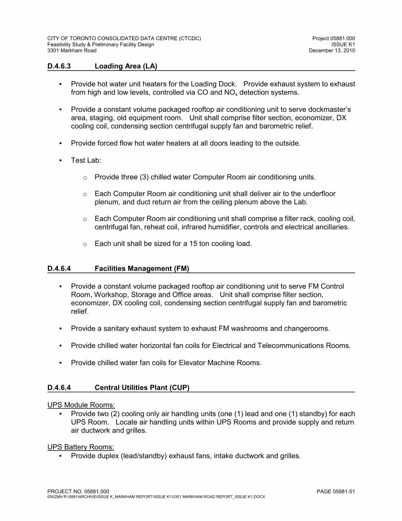
CITY OF TORONTO CONSOLIDATED DATA CENTRE (CTCDC) Project 05881.000 Feasibility Study & Preliminary Facility Design ISSUE K1 3301 Markham Road December 13, 2010
PROJECT NO. 05881.000 PAGE 05881-51 ©WZMH R:\5881\ARCHIVE\ISSUE K_MARKHAM REPORT\ISSUE K1\3301 MARKHAM ROAD REPORT_ISSUE K1.DOCX
D.4.6.3 Loading Area (LA) • Provide hot water unit heaters for the Loading Dock. Provide exhaust system to exhaust
from high and low levels, controlled via CO and NOx detection systems.
• Provide a constant volume packaged rooftop air conditioning unit to serve dockmaster’s area, staging, old equipment room. Unit shall comprise filter section, economizer, DX cooling coil, condensing section centrifugal supply fan and barometric relief.
• Provide forced flow hot water heaters at all doors leading to the outside.
• Test Lab:
o Provide three (3) chilled water Computer Room air conditioning units.
o Each Computer Room air conditioning unit shall deliver air to the underfloor plenum, and duct return air from the ceiling plenum above the Lab.
o Each Computer Room air conditioning unit shall comprise a filter rack, cooling coil, centrifugal fan, reheat coil, infrared humidifier, controls and electrical ancillaries.
o Each unit shall be sized for a 15 ton cooling load. D.4.6.4 Facilities Management (FM)
• Provide a constant volume packaged rooftop air conditioning unit to serve FM Control Room, Workshop, Storage and Office areas. Unit shall comprise filter section, economizer, DX cooling coil, condensing section centrifugal supply fan and barometric relief.
• Provide a sanitary exhaust system to exhaust FM washrooms and changerooms.
• Provide chilled water horizontal fan coils for Electrical and Telecommunications Rooms.
• Provide chilled water fan coils for Elevator Machine Rooms. D.4.6.4 Central Utilities Plant (CUP) UPS Module Rooms:
• Provide two (2) cooling only air handling units (one (1) lead and one (1) standby) for each UPS Room. Locate air handling units within UPS Rooms and provide supply and return air ductwork and grilles.
UPS Battery Rooms: • Provide duplex (lead/standby) exhaust fans, intake ductwork and grilles.
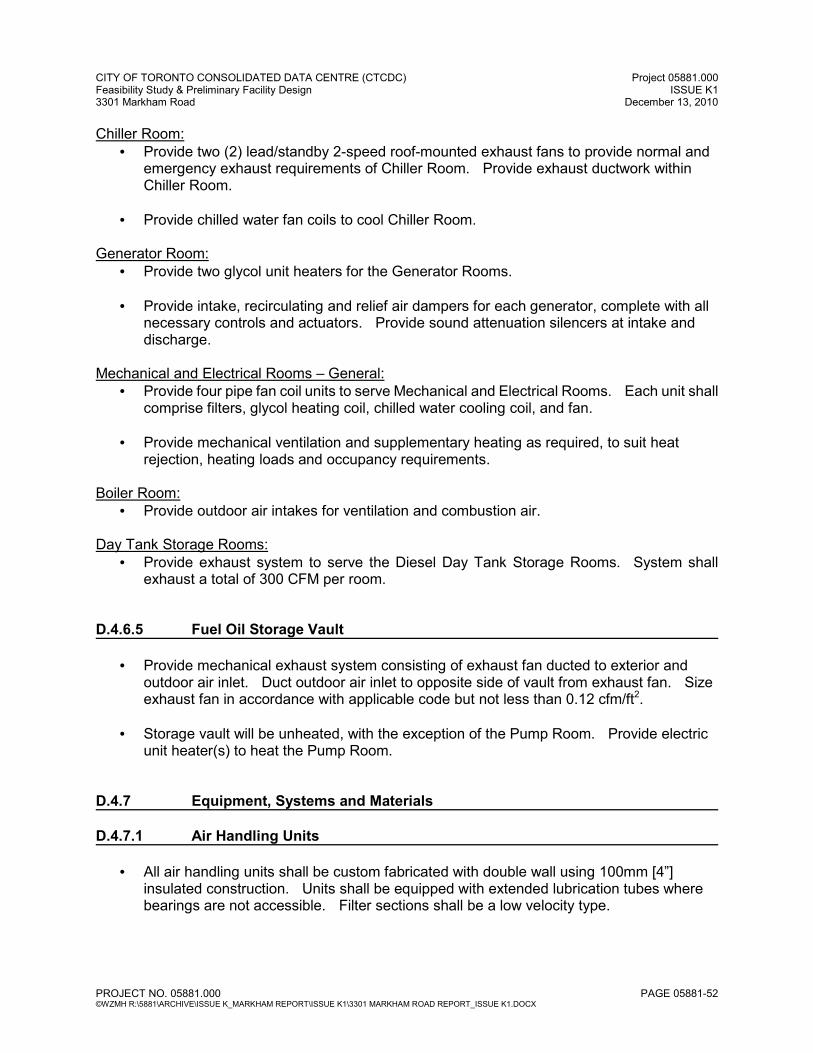
CITY OF TORONTO CONSOLIDATED DATA CENTRE (CTCDC) Project 05881.000 Feasibility Study & Preliminary Facility Design ISSUE K1 3301 Markham Road December 13, 2010
PROJECT NO. 05881.000 PAGE 05881-52 ©WZMH R:\5881\ARCHIVE\ISSUE K_MARKHAM REPORT\ISSUE K1\3301 MARKHAM ROAD REPORT_ISSUE K1.DOCX
Chiller Room: • Provide two (2) lead/standby 2-speed roof-mounted exhaust fans to provide normal and
emergency exhaust requirements of Chiller Room. Provide exhaust ductwork within Chiller Room.
• Provide chilled water fan coils to cool Chiller Room.
Generator Room: • Provide two glycol unit heaters for the Generator Rooms.
• Provide intake, recirculating and relief air dampers for each generator, complete with all
necessary controls and actuators. Provide sound attenuation silencers at intake and discharge.
Mechanical and Electrical Rooms – General: • Provide four pipe fan coil units to serve Mechanical and Electrical Rooms. Each unit shall
comprise filters, glycol heating coil, chilled water cooling coil, and fan.
• Provide mechanical ventilation and supplementary heating as required, to suit heat rejection, heating loads and occupancy requirements.
Boiler Room: • Provide outdoor air intakes for ventilation and combustion air.
Day Tank Storage Rooms:
• Provide exhaust system to serve the Diesel Day Tank Storage Rooms. System shall exhaust a total of 300 CFM per room.
D.4.6.5 Fuel Oil Storage Vault
• Provide mechanical exhaust system consisting of exhaust fan ducted to exterior and outdoor air inlet. Duct outdoor air inlet to opposite side of vault from exhaust fan. Size exhaust fan in accordance with applicable code but not less than 0.12 cfm/ft2.
• Storage vault will be unheated, with the exception of the Pump Room. Provide electric unit heater(s) to heat the Pump Room.
D.4.7 Equipment, Systems and Materials D.4.7.1 Air Handling Units
• All air handling units shall be custom fabricated with double wall using 100mm [4”] insulated construction. Units shall be equipped with extended lubrication tubes where bearings are not accessible. Filter sections shall be a low velocity type.
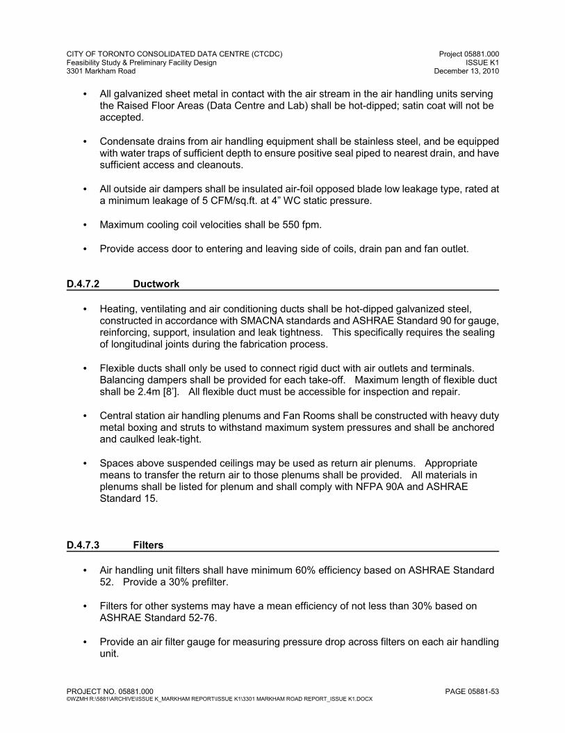
CITY OF TORONTO CONSOLIDATED DATA CENTRE (CTCDC) Project 05881.000 Feasibility Study & Preliminary Facility Design ISSUE K1 3301 Markham Road December 13, 2010
PROJECT NO. 05881.000 PAGE 05881-53 ©WZMH R:\5881\ARCHIVE\ISSUE K_MARKHAM REPORT\ISSUE K1\3301 MARKHAM ROAD REPORT_ISSUE K1.DOCX
• All galvanized sheet metal in contact with the air stream in the air handling units serving the Raised Floor Areas (Data Centre and Lab) shall be hot-dipped; satin coat will not be accepted.
• Condensate drains from air handling equipment shall be stainless steel, and be equipped with water traps of sufficient depth to ensure positive seal piped to nearest drain, and have sufficient access and cleanouts.
• All outside air dampers shall be insulated air-foil opposed blade low leakage type, rated at a minimum leakage of 5 CFM/sq.ft. at 4” WC static pressure.
• Maximum cooling coil velocities shall be 550 fpm.
• Provide access door to entering and leaving side of coils, drain pan and fan outlet.
D.4.7.2 Ductwork
• Heating, ventilating and air conditioning ducts shall be hot-dipped galvanized steel, constructed in accordance with SMACNA standards and ASHRAE Standard 90 for gauge, reinforcing, support, insulation and leak tightness. This specifically requires the sealing of longitudinal joints during the fabrication process.
• Flexible ducts shall only be used to connect rigid duct with air outlets and terminals. Balancing dampers shall be provided for each take-off. Maximum length of flexible duct shall be 2.4m [8’]. All flexible duct must be accessible for inspection and repair.
• Central station air handling plenums and Fan Rooms shall be constructed with heavy duty metal boxing and struts to withstand maximum system pressures and shall be anchored and caulked leak-tight.
• Spaces above suspended ceilings may be used as return air plenums. Appropriate means to transfer the return air to those plenums shall be provided. All materials in plenums shall be listed for plenum and shall comply with NFPA 90A and ASHRAE Standard 15.
D.4.7.3 Filters
• Air handling unit filters shall have minimum 60% efficiency based on ASHRAE Standard 52. Provide a 30% prefilter.
• Filters for other systems may have a mean efficiency of not less than 30% based on ASHRAE Standard 52-76.
• Provide an air filter gauge for measuring pressure drop across filters on each air handling unit.
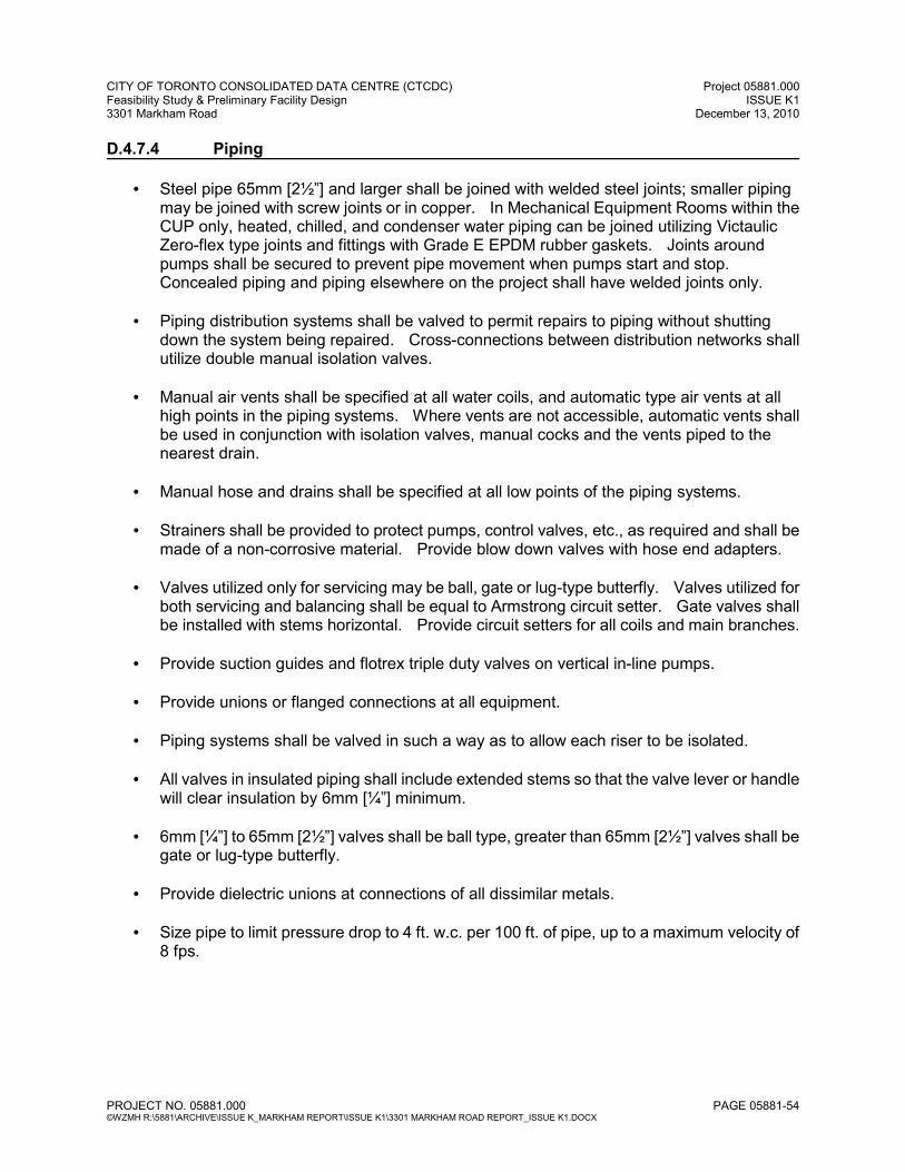
CITY OF TORONTO CONSOLIDATED DATA CENTRE (CTCDC) Project 05881.000 Feasibility Study & Preliminary Facility Design ISSUE K1 3301 Markham Road December 13, 2010
PROJECT NO. 05881.000 PAGE 05881-54 ©WZMH R:\5881\ARCHIVE\ISSUE K_MARKHAM REPORT\ISSUE K1\3301 MARKHAM ROAD REPORT_ISSUE K1.DOCX
D.4.7.4 Piping
• Steel pipe 65mm [2½”] and larger shall be joined with welded steel joints; smaller piping may be joined with screw joints or in copper. In Mechanical Equipment Rooms within the CUP only, heated, chilled, and condenser water piping can be joined utilizing Victaulic Zero-flex type joints and fittings with Grade E EPDM rubber gaskets. Joints around pumps shall be secured to prevent pipe movement when pumps start and stop. Concealed piping and piping elsewhere on the project shall have welded joints only.
• Piping distribution systems shall be valved to permit repairs to piping without shutting down the system being repaired. Cross-connections between distribution networks shall utilize double manual isolation valves.
• Manual air vents shall be specified at all water coils, and automatic type air vents at all high points in the piping systems. Where vents are not accessible, automatic vents shall be used in conjunction with isolation valves, manual cocks and the vents piped to the nearest drain.
• Manual hose and drains shall be specified at all low points of the piping systems.
• Strainers shall be provided to protect pumps, control valves, etc., as required and shall be made of a non-corrosive material. Provide blow down valves with hose end adapters.
• Valves utilized only for servicing may be ball, gate or lug-type butterfly. Valves utilized for both servicing and balancing shall be equal to Armstrong circuit setter. Gate valves shall be installed with stems horizontal. Provide circuit setters for all coils and main branches.
• Provide suction guides and flotrex triple duty valves on vertical in-line pumps.
• Provide unions or flanged connections at all equipment.
• Piping systems shall be valved in such a way as to allow each riser to be isolated.
• All valves in insulated piping shall include extended stems so that the valve lever or handle will clear insulation by 6mm [¼”] minimum.
• 6mm [¼”] to 65mm [2½”] valves shall be ball type, greater than 65mm [2½”] valves shall be gate or lug-type butterfly.
• Provide dielectric unions at connections of all dissimilar metals.
• Size pipe to limit pressure drop to 4 ft. w.c. per 100 ft. of pipe, up to a maximum velocity of 8 fps.
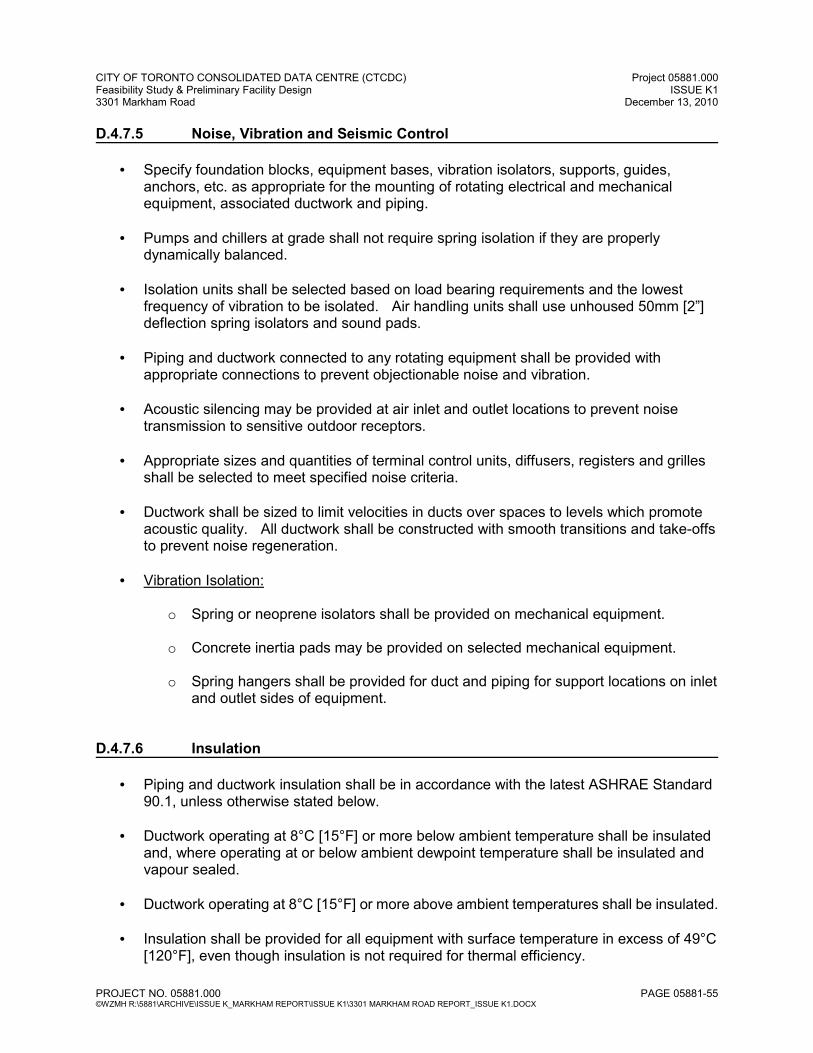
CITY OF TORONTO CONSOLIDATED DATA CENTRE (CTCDC) Project 05881.000 Feasibility Study & Preliminary Facility Design ISSUE K1 3301 Markham Road December 13, 2010
PROJECT NO. 05881.000 PAGE 05881-55 ©WZMH R:\5881\ARCHIVE\ISSUE K_MARKHAM REPORT\ISSUE K1\3301 MARKHAM ROAD REPORT_ISSUE K1.DOCX
D.4.7.5 Noise, Vibration and Seismic Control
• Specify foundation blocks, equipment bases, vibration isolators, supports, guides, anchors, etc. as appropriate for the mounting of rotating electrical and mechanical equipment, associated ductwork and piping.
• Pumps and chillers at grade shall not require spring isolation if they are properly dynamically balanced.
• Isolation units shall be selected based on load bearing requirements and the lowest frequency of vibration to be isolated. Air handling units shall use unhoused 50mm [2”] deflection spring isolators and sound pads.
• Piping and ductwork connected to any rotating equipment shall be provided with appropriate connections to prevent objectionable noise and vibration.
• Acoustic silencing may be provided at air inlet and outlet locations to prevent noise transmission to sensitive outdoor receptors.
• Appropriate sizes and quantities of terminal control units, diffusers, registers and grilles shall be selected to meet specified noise criteria.
• Ductwork shall be sized to limit velocities in ducts over spaces to levels which promote acoustic quality. All ductwork shall be constructed with smooth transitions and take-offs to prevent noise regeneration.
• Vibration Isolation:
o Spring or neoprene isolators shall be provided on mechanical equipment.
o Concrete inertia pads may be provided on selected mechanical equipment.
o Spring hangers shall be provided for duct and piping for support locations on inlet and outlet sides of equipment.
D.4.7.6 Insulation
• Piping and ductwork insulation shall be in accordance with the latest ASHRAE Standard 90.1, unless otherwise stated below.
• Ductwork operating at 8°C [15°F] or more below ambient temperature shall be insulated and, where operating at or below ambient dewpoint temperature shall be insulated and vapour sealed.
• Ductwork operating at 8°C [15°F] or more above ambient temperatures shall be insulated.
• Insulation shall be provided for all equipment with surface temperature in excess of 49°C [120°F], even though insulation is not required for thermal efficiency.

CITY OF TORONTO CONSOLIDATED DATA CENTRE (CTCDC) Project 05881.000 Feasibility Study & Preliminary Facility Design ISSUE K1 3301 Markham Road December 13, 2010
PROJECT NO. 05881.000 PAGE 05881-56 ©WZMH R:\5881\ARCHIVE\ISSUE K_MARKHAM REPORT\ISSUE K1\3301 MARKHAM ROAD REPORT_ISSUE K1.DOCX
• Insulation shall be provided for all equipment with surface temperature less than 10°C [50°F], even though insulation is not required for thermal efficiency.
• All insulation exposed to weather shall be adequately protected and shall be rated and protected for exposure to ultraviolet and infrared light. All exposed piping insulation on roof shall have aluminum recovery jacket.
• Provide lagged canvas recovery jackets for all exposed piping and ductwork.
• Provide insulation materials meeting all applicable Fire Codes. Provide fire stop materials when penetrating fire partitions.
• Provide rigid insulation materials in exposed areas.
• Insulate all electrically traced piping.
• Provide insulation for the following services:
Piping: DUTY
PIPE SIZE
INSULATION THICKNESS
VAPOUR BARRIER
Domestic Cold Water 25mm [1”] and under Over 25mm [1”]
12mm [½”] 25mm [1”]
Y Y
Domestic Hot, Recirculation, and Tempered Water
50mm [2”] and under Over 50mm [2”]
25mm [1”] 40mm [1½”]
N N
Horizontal Storm and Sanitary All Sizes
25mm [1”]
Y
Condensate Drainage All Sizes 12mm [½”] Y
Closed Loop Cooler, Make-Up, Overflow, Drain and Equalizer Lines
All Sizes
25mm [1”]
Y
Dry Sprinkler Drum Drips All Sizes 25mm [1”] Y
Chilled Water Supply and Return
100mm [4”] and under Over 100mm [4”]
25mm [1”] 50mm [2”]
Y Y
Condenser (Glycol) Supply and Return (where used for water-side free cooling)
100mm [4”] and under Over 100mm [4”]
25mm [1”] 40mm [1½”]
Y Y
Heating Water Supply and Return
All Sizes, Except Runouts to 50mm [2”]
25mm [1”] 12mm [½”]
N N
Steam and Condensate 50mm [2”] and under Over 50mm [2”]
40mm [1½”] 50mm [2”]
N N
Refrigerant Suction Lines All Sizes 25mm [1”] Y
Generator Exhaust All Sizes 50mm [2”] N

CITY OF TORONTO CONSOLIDATED DATA CENTRE (CTCDC) Project 05881.000 Feasibility Study & Preliminary Facility Design ISSUE K1 3301 Markham Road December 13, 2010
PROJECT NO. 05881.000 PAGE 05881-57 ©WZMH R:\5881\ARCHIVE\ISSUE K_MARKHAM REPORT\ISSUE K1\3301 MARKHAM ROAD REPORT_ISSUE K1.DOCX
Sheet Metal: DUTY
INSULATION THICKNESS
VAPOUR BARRIER
Panels Behind Unused Portion of Louvres 50mm [2”] Y
Outside Air Plenums and Ducts 50mm [2”] Y
Mixed Air Plenums and Ducts 40mm [1½”] Y
Relief and Exhaust Air Plenums 40mm [1½”] Y
Final 3m [10’] Exhaust Air Ducts 25mm [1”] Y
Field Fabricated Unit Casings 40mm [1½”] Y
Rectangular or Rigid Round Supply Air Ductwork (Note 1) 25mm [1”] Y
NOTES: 1. Rigid supply air ductwork located within the Raised Floor shall not be insulated.
Equipment: DUTY
INSULATION THICKNESS
VAPOUR BARRIER
Water Meter 40mm [1½”] Y
Centrifugal Refrigeration Machines: - Suction Lines - Chiller Shells
25mm [1”] 25mm [1”]
Y Y
Generator Silencer, High Temperature 50mm [2”] N
D.4.8 Building Automation System
• Provide Building Automation System (BAS) incorporating direct digital controls (DDC) and distributed processing. The BAS shall be an independent system, separate from fire, security, and refrigeration plant control. The BAS will be interfaced to these other systems to provide key status information. BAS shall also control lighting system.
• Provide all wiring, conduit, piping installation materials, supervision and labour, including calibration, commissioning, software programming and data base generation, generation of graphics, and all additional work necessary to provide a complete and fully operating system.
• Provide all control wiring. Install in EMT conduit, and otherwise comply with Division 16 requirements. Provide power wiring from nearest 120 Volt emergency power panel to each field device.
• Temperature and humidity controls shall be in accordance with ASHRAE 90.1 Standards, in addition to the requirements stated herein.
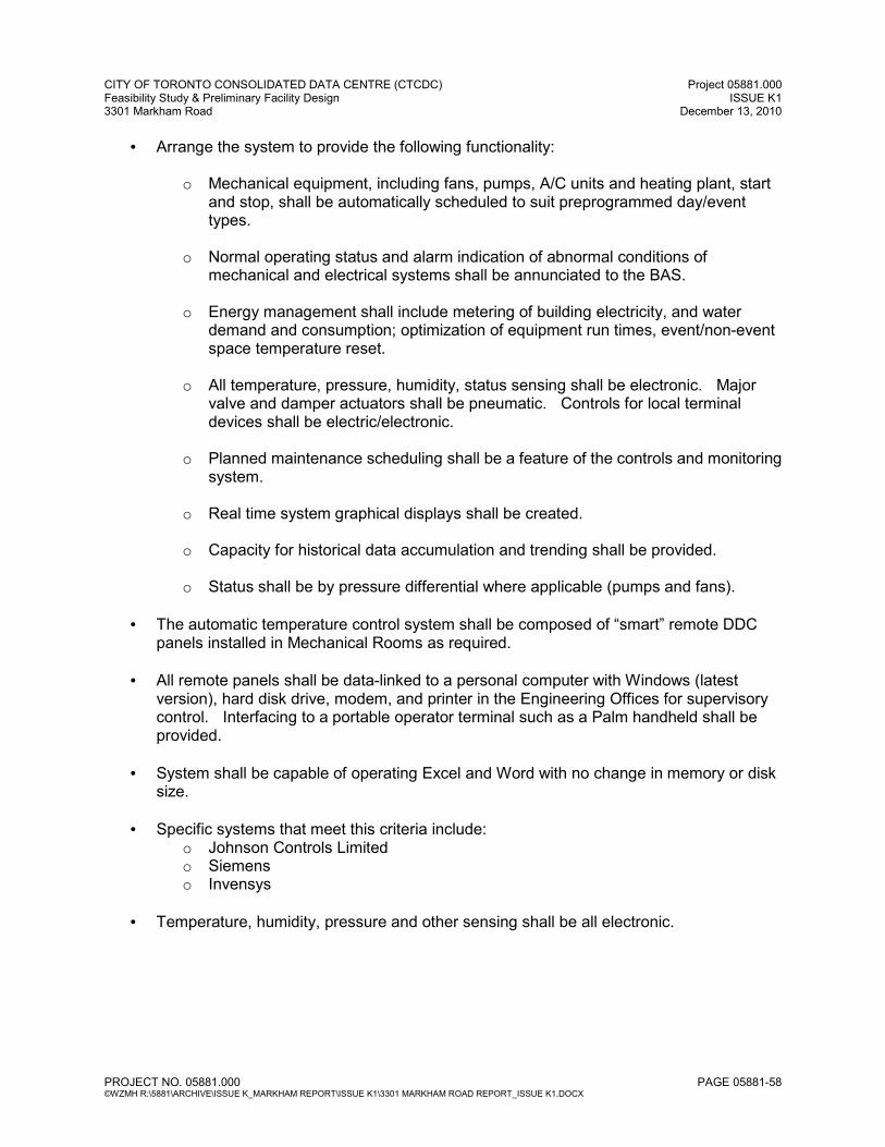
CITY OF TORONTO CONSOLIDATED DATA CENTRE (CTCDC) Project 05881.000 Feasibility Study & Preliminary Facility Design ISSUE K1 3301 Markham Road December 13, 2010
PROJECT NO. 05881.000 PAGE 05881-58 ©WZMH R:\5881\ARCHIVE\ISSUE K_MARKHAM REPORT\ISSUE K1\3301 MARKHAM ROAD REPORT_ISSUE K1.DOCX
• Arrange the system to provide the following functionality:
o Mechanical equipment, including fans, pumps, A/C units and heating plant, start and stop, shall be automatically scheduled to suit preprogrammed day/event types.
o Normal operating status and alarm indication of abnormal conditions of mechanical and electrical systems shall be annunciated to the BAS.
o Energy management shall include metering of building electricity, and water demand and consumption; optimization of equipment run times, event/non-event space temperature reset.
o All temperature, pressure, humidity, status sensing shall be electronic. Major valve and damper actuators shall be pneumatic. Controls for local terminal devices shall be electric/electronic.
o Planned maintenance scheduling shall be a feature of the controls and monitoring system.
o Real time system graphical displays shall be created.
o Capacity for historical data accumulation and trending shall be provided.
o Status shall be by pressure differential where applicable (pumps and fans).
• The automatic temperature control system shall be composed of “smart” remote DDC panels installed in Mechanical Rooms as required.
• All remote panels shall be data-linked to a personal computer with Windows (latest version), hard disk drive, modem, and printer in the Engineering Offices for supervisory control. Interfacing to a portable operator terminal such as a Palm handheld shall be provided.
• System shall be capable of operating Excel and Word with no change in memory or disk size.
• Specific systems that meet this criteria include: o Johnson Controls Limited o Siemens o Invensys
• Temperature, humidity, pressure and other sensing shall be all electronic.
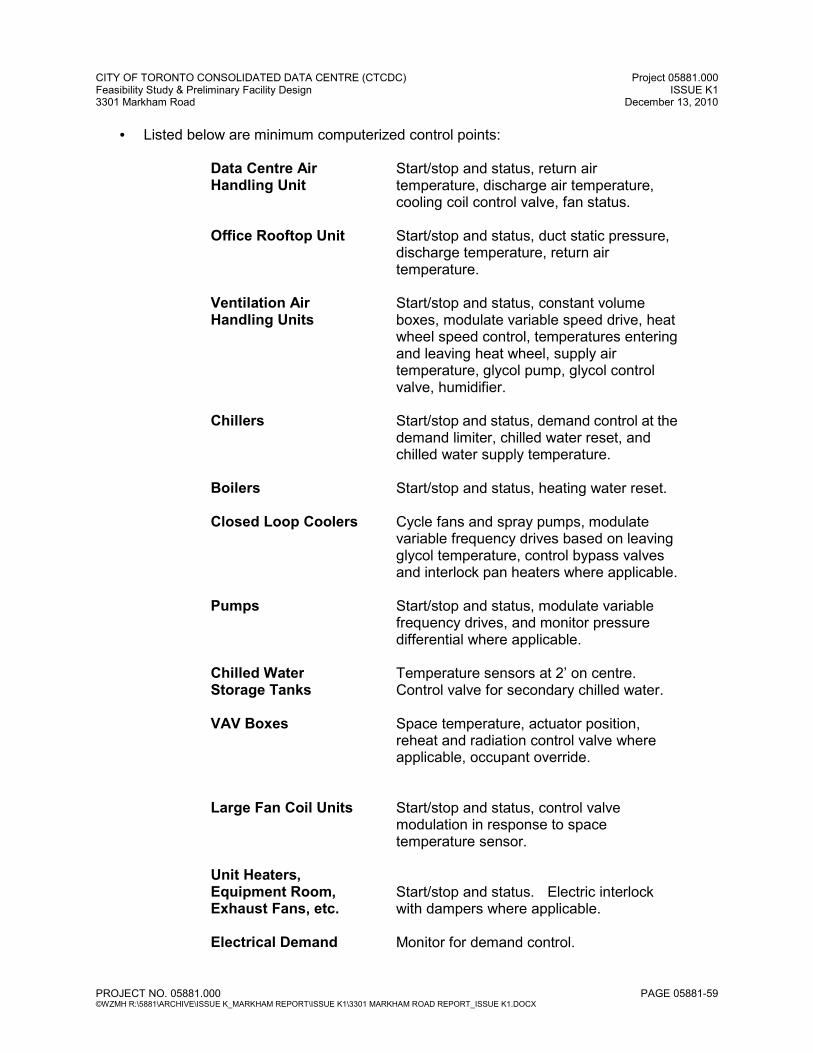
CITY OF TORONTO CONSOLIDATED DATA CENTRE (CTCDC) Project 05881.000 Feasibility Study & Preliminary Facility Design ISSUE K1 3301 Markham Road December 13, 2010
PROJECT NO. 05881.000 PAGE 05881-59 ©WZMH R:\5881\ARCHIVE\ISSUE K_MARKHAM REPORT\ISSUE K1\3301 MARKHAM ROAD REPORT_ISSUE K1.DOCX
• Listed below are minimum computerized control points:
Data Centre Air Handling Unit
Start/stop and status, return air temperature, discharge air temperature, cooling coil control valve, fan status.
Office Rooftop Unit Start/stop and status, duct static pressure, discharge temperature, return air temperature.
Ventilation Air Handling Units
Start/stop and status, constant volume boxes, modulate variable speed drive, heat wheel speed control, temperatures entering and leaving heat wheel, supply air temperature, glycol pump, glycol control valve, humidifier.
Chillers Start/stop and status, demand control at the demand limiter, chilled water reset, and chilled water supply temperature.
Boilers Start/stop and status, heating water reset.
Closed Loop Coolers Cycle fans and spray pumps, modulate variable frequency drives based on leaving glycol temperature, control bypass valves and interlock pan heaters where applicable.
Pumps Start/stop and status, modulate variable frequency drives, and monitor pressure differential where applicable.
Chilled Water Storage Tanks
Temperature sensors at 2’ on centre. Control valve for secondary chilled water.
VAV Boxes Space temperature, actuator position, reheat and radiation control valve where applicable, occupant override.
Large Fan Coil Units Start/stop and status, control valve modulation in response to space temperature sensor.
Unit Heaters, Equipment Room, Exhaust Fans, etc.
Start/stop and status. Electric interlock with dampers where applicable.
Electrical Demand Monitor for demand control.
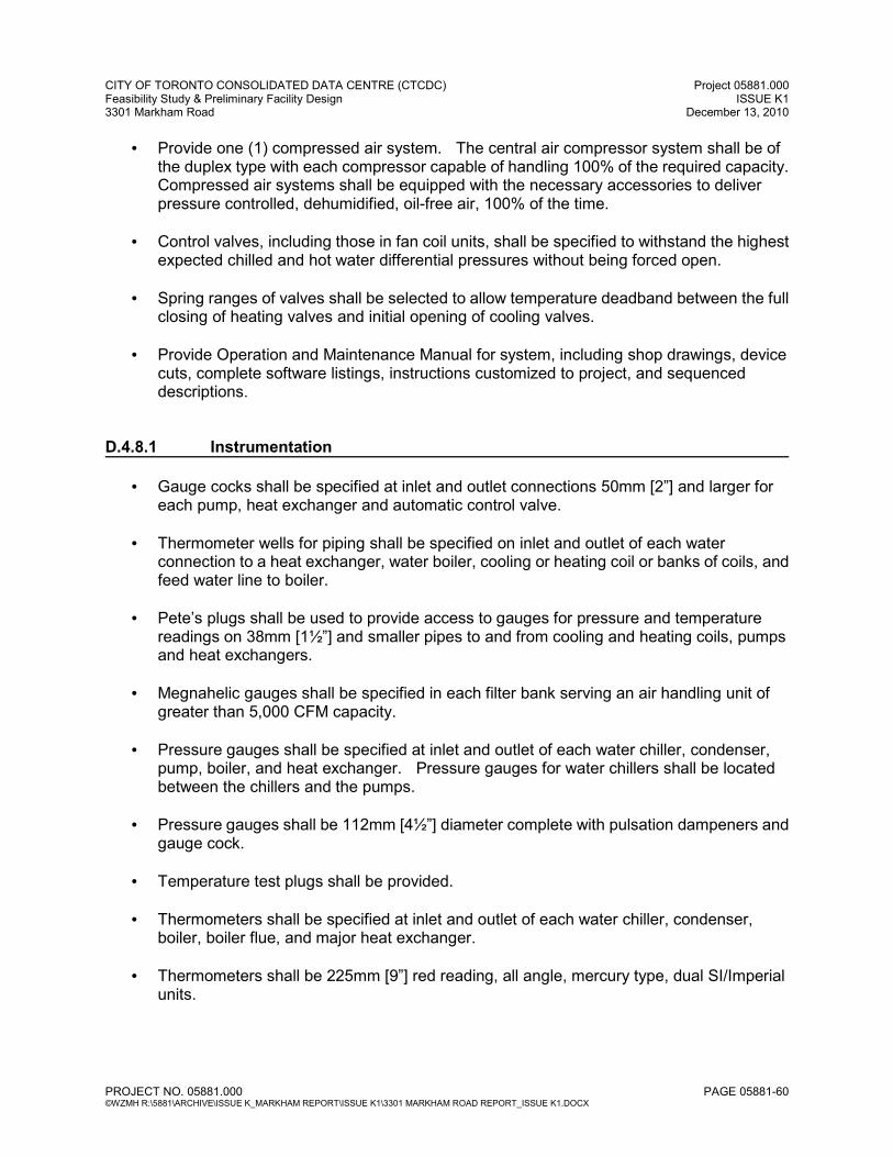
CITY OF TORONTO CONSOLIDATED DATA CENTRE (CTCDC) Project 05881.000 Feasibility Study & Preliminary Facility Design ISSUE K1 3301 Markham Road December 13, 2010
PROJECT NO. 05881.000 PAGE 05881-60 ©WZMH R:\5881\ARCHIVE\ISSUE K_MARKHAM REPORT\ISSUE K1\3301 MARKHAM ROAD REPORT_ISSUE K1.DOCX
• Provide one (1) compressed air system. The central air compressor system shall be of the duplex type with each compressor capable of handling 100% of the required capacity. Compressed air systems shall be equipped with the necessary accessories to deliver pressure controlled, dehumidified, oil-free air, 100% of the time.
• Control valves, including those in fan coil units, shall be specified to withstand the highest expected chilled and hot water differential pressures without being forced open.
• Spring ranges of valves shall be selected to allow temperature deadband between the full closing of heating valves and initial opening of cooling valves.
• Provide Operation and Maintenance Manual for system, including shop drawings, device cuts, complete software listings, instructions customized to project, and sequenced descriptions.
D.4.8.1 Instrumentation
• Gauge cocks shall be specified at inlet and outlet connections 50mm [2”] and larger for each pump, heat exchanger and automatic control valve.
• Thermometer wells for piping shall be specified on inlet and outlet of each water connection to a heat exchanger, water boiler, cooling or heating coil or banks of coils, and feed water line to boiler.
• Pete’s plugs shall be used to provide access to gauges for pressure and temperature readings on 38mm [1½”] and smaller pipes to and from cooling and heating coils, pumps and heat exchangers.
• Megnahelic gauges shall be specified in each filter bank serving an air handling unit of greater than 5,000 CFM capacity.
• Pressure gauges shall be specified at inlet and outlet of each water chiller, condenser, pump, boiler, and heat exchanger. Pressure gauges for water chillers shall be located between the chillers and the pumps.
• Pressure gauges shall be 112mm [4½”] diameter complete with pulsation dampeners and gauge cock.
• Temperature test plugs shall be provided.
• Thermometers shall be specified at inlet and outlet of each water chiller, condenser, boiler, boiler flue, and major heat exchanger.
• Thermometers shall be 225mm [9”] red reading, all angle, mercury type, dual SI/Imperial units.
CITY OF TORONTO CONSOLIDATED DATA CENTRE (CTCDC) Project 05881.000 Feasibility Study & Preliminary Facility Design ISSUE K1 3301 Markham Road December 13, 2010
PROJECT NO. 05881.000 PAGE 05881-61 ©WZMH R:\5881\ARCHIVE\ISSUE K_MARKHAM REPORT\ISSUE K1\3301 MARKHAM ROAD REPORT_ISSUE K1.DOCX
D.4.8.2 Metering Make-up meters shall be installed on chilled water, closed loop cooler, and ground irrigation systems. D.4.8.3 Freeze Protection Where cooling coils require freeze protection, they shall be equipped with low temperature safety controls, set at 4°C [40°F], to stop the fan and activate an alarm. High efficiency mixing boxes shall also be specified as required to improve outside air/return air mixing. D.4.8.4 Water Detection Provide water detection systems for:
• Penthouses.
• Under raised floor (at each floor drain).
• Along Mechanical Service Corridors.
• All main Electrical and Communications Rooms.
D.4.9 Commissioning
• All mechanical systems shall be commissioned by the Mechanical Contractor under the direction and presence of the General Contractor, for final witness checking by Hidi Rae Consulting Engineers Inc.
• Mechanical commissioning objectives shall be as follows:
o To ensure systems are properly started-up and verified prior to being put into operation.
o To ensure the mechanical systems are operating within design parameters.
o To ensure that the completed system meets City of Toronto’s requirements.
o To optimize the performance of all systems throughout all seasons.
o To ensure that City of Toronto’s staff receive proper training through either supplier or contractor operation and maintenance seminars.
CITY OF TORONTO CONSOLIDATED DATA CENTRE (CTCDC) Project 05881.000 Feasibility Study & Preliminary Facility Design ISSUE K1 3301 Markham Road December 13, 2010
PROJECT NO. 05881.000 PAGE 05881-62 ©WZMH R:\5881\ARCHIVE\ISSUE K_MARKHAM REPORT\ISSUE K1\3301 MARKHAM ROAD REPORT_ISSUE K1.DOCX
• Mechanical commissioning execution shall be as follows:
o The mechanical systems shall be performance tested once all piping, electrical and HVAC controls have been completed and put into operation as per the contract documents. This work shall include:
� Cleaning, flushing, pressure testing, water treatment of all hydronic piping systems.
� Water balance of all hydronic systems (by others).
� Cleaning, random pressure testing and sealing of all air duct systems.
� Air balance, including three (3) trial balances (by others).
� Air pattern testing (by others) in: • Meeting Rooms • Other Areas as selected
� Air delivery testing (by others) in the Raised Floor Area.
� Noise checks.
� Control system point and control loop functional checkout.
� Control system data entry for operating and alarm setpoints, operating
schedules, operator password protection set-up, and other software set-up.
� Equipment start-up checklists, start-up and check-out.
o A “Mechanical Equipment and System Start-up Verification Sheet” shall be completed for each mechanical equipment or system as required by the Mechanical Contractor.
o Hidi Rae Consulting Engineers Inc. shall confirm operation as per design through on-site review of systems and Air/Water Balance Reports provided by the Mechanical Contractor. Confirmation of setpoint values shall be through the control system.
o The Mechanical Contractor shall provide training to City of Toronto’s operations staff through use of either manufacturer representatives or contractor site personnel.
o Locations of valves, access doors and ceiling mounted equipment shall be identified and reviewed with City of Toronto’s operations staff.

CITY OF TORONTO CONSOLIDATED DATA CENTRE (CTCDC) Project 05881.000 Feasibility Study & Preliminary Facility Design ISSUE K1 3301 Markham Road December 13, 2010
PROJECT NO. 05881.000 PAGE 05881-63 ©WZMH R:\5881\ARCHIVE\ISSUE K_MARKHAM REPORT\ISSUE K1\3301 MARKHAM ROAD REPORT_ISSUE K1.DOCX
o Specialty subcontractors, i.e., sprinklers, controls, and primary equipment suppliers, shall provide additional training to City of Toronto’s staff on the operation and maintenance of these systems.
o The Mechanical Contractor and equipment manufacturers shall work with the Mechanical Consultant and City of Toronto personnel to optimize the operation of all systems and equipment throughout an entire year.
• Water Treatment:
o All water treatment chemicals and equipment shall be demonstrated by the supplier.
• Cleaning, Testing and Balancing Air and Water Systems:
o Prior to start-up, all systems shall be adequately cleaned and flushed to remove dirt, debris and foreign materials from all hot water systems, chilled water systems, glycol systems, condensate systems, steam generator systems, and any and all other piping, HVAC equipment, fans, ducts, air handlers and blowers.
o Prior to initial operation, all systems and equipment installation shall be verified to be in accordance with drawings and specifications.
o Temperature and humidity control systems, electrical interlocks, fire protection interlocks, shall all be operational, adjusted and calibrated in accordance with drawings and specifications.
• Training and Instructions:
o Operating personnel shall be provided with both written and oral instructions and training on all HVAC equipment, controls, and mechanical systems components. Training shall also include the operation and maintenance of fire protection and life safety equipment. This includes emergency power systems, smoke control systems, fire alarm and detection systems, automatic sprinkler system, standpipes and fire pumps. Training shall be provided by persons qualified and appropriately certified to provide such training.
o Provide a brief narrative of the building function and its mode of operations.
o Provide Operation and Maintenance Manuals with manufacturer’s catalogue information on all operative equipment (mechanical, electrical starters, plumbing, specialty items, etc.). These catalogue sheets shall show dimensions, installation instructions and other pertinent engineering data regarding capacity, safety, etc.
o Provide valve schedules and brass tags, indicating function and location. Provide schematic and diagrammatic location of all emergency and zone cut-off valves.

CITY OF TORONTO CONSOLIDATED DATA CENTRE (CTCDC) Project 05881.000 Feasibility Study & Preliminary Facility Design ISSUE K1 3301 Markham Road December 13, 2010
PROJECT NO. 05881.000 PAGE 05881-64 ©WZMH R:\5881\ARCHIVE\ISSUE K_MARKHAM REPORT\ISSUE K1\3301 MARKHAM ROAD REPORT_ISSUE K1.DOCX
o Provide manufacturer’s name, model number, applicable manual number, and publications pertaining to maintenance on major pieces of equipment. This shall be developed according to manufacturer’s recommendations, executed by standard engineering practices.
o Provide a scheduled listing of all design, construction and as-built drawings by drawing number and their function. All drawings shall be on white prints and shall be turned over to The City of Toronto after the beneficial occupancy of the building. A CD-ROM as-built set of drawings shall also be provided.
o Include copies of approved shop drawings and Test and Balance Reports with the Operation and Maintenance Manuals.
• Guarantees and Warranties:
o All HVAC equipment and installed mechanical systems including, but not limited to, piping, controls, fans, pumps, air handlers, chillers, boilers, tanks, etc., shall be covered by a full warranty for both parts and labour for a full calendar year (longer where specified) after Substantial Completion.
o Any and all guarantees and warranties shall be provided in writing both from manufacturers and installers prior to system acceptance.
o Service companies carrying such guarantees or warranties shall be located to provide service on a 24-hour basis within a two (2) hour time period.
o Provide contractor and subcontractor 24-hour telephone numbers, cell phone numbers and beeper numbers.
CITY OF TORONTO CONSOLIDATED DATA CENTRE (CTCDC) Project 05881.000 Feasibility Study & Preliminary Facility Design ISSUE K1 3301 Markham Road December 13, 2010
PROJECT NO. 05881.000 PAGE 05881-65 ©WZMH R:\5881\ARCHIVE\ISSUE K_MARKHAM REPORT\ISSUE K1\3301 MARKHAM ROAD REPORT_ISSUE K1.DOCX
D.5 ELECTRICAL REQUIREMENTS D.5.1 Outline Scope of Work This design brief deals with the electrical engineering aspects for the CTCDC computer centre. The system and component descriptions contained herein this report reflect the concept design at the present stage and generally combine the present City’s Decision Matrix requirements and industry best practices design standards. The electrical systems will include but not be limited to the following:
• 27.6KV Main Incoming Hydro Service – THES standard metal enclosed switchgear with load break switches and THES revenue metering components
• Medium voltage 27.6KV Main Power Distribution system • Liquid Cooled power transformers – CSA C88 Standard complete with Intelligent
Transformer Monitoring System ( ITM 509 or equal) • 15KV UPS Input Power distribution system • Prime rated engine coupled medium voltage Piller Rotary UPS system with Dual Critical
and Essential Power output bus and with Energy Storage “Power Bridge” devices in N+1 configuration15KV UPS powered output distribution system
• 600V rated essential powered distribution system. • 600V and 208V “Raised Floor” power distribution systems • Emergency Power Generation System • Power Monitoring and Control System (PMCS) Data Centre power distribution panels and
Remote Power Panels Starline Plug-in type busway system and plug-in devices • Intelligent Fire Alarm and two way emergency voice communication system • Lighting system • Intelligent Lighting Control systems • Emergency lighting system • Emergency Lighting battery equipment with remote lightheads • Primary and Secondary Grounding • Lightning protection system. • Computer room water detection and grounding systems • Security Access Control and CCTV Surveillance Systems. • Duress Alarm System • Voice & data empty raceway systems
Applicable Standards and Guidelines:
• CSA C282 Emergency Power for Buildings • CSA-B79 Code for Installation Of Lightning Rods • CAN/ULC S524 Standard for the Installation of Fire Alarm Systems • CAN/ULC S537 Standard for the Verification of Fire Alarm System Installations
CITY OF TORONTO CONSOLIDATED DATA CENTRE (CTCDC) Project 05881.000 Feasibility Study & Preliminary Facility Design ISSUE K1 3301 Markham Road December 13, 2010
PROJECT NO. 05881.000 PAGE 05881-66 ©WZMH R:\5881\ARCHIVE\ISSUE K_MARKHAM REPORT\ISSUE K1\3301 MARKHAM ROAD REPORT_ISSUE K1.DOCX
D.5.2 General Requirements
All components will be of a modular construction for fast and efficient servicing and to provide an
Uptime Institute Tier III classification site infrastructure Data Center.
All electrical work will comply with or exceed the minimum requirements of the applicable codes,
rules and regulations of the latest:
• Ontario Building Code
• Ontario Hydro Electrical Safety Code National Electrical Code
• National fire code of Canada
• Ontario Lightning Rod Act
• Local Electrical Codes and Requirements
• Transport Canada
• CSA Standards
• IEEE Standards
• IES Standards
• ASHRAE Standards
• Ontario Ministry of Environment’s Certificate of Assessment requirements
• Any other governing Authority Having Jurisdiction
Data Centre Infrastructure Tier Standard: Topology as prepared by Uptime Institute, LLC will be
used as design reference.
All materials will be new and free of defects. Canadian products will be used where possible.
The building complex will utilize state of the art components intended to satisfy the needs of a
Data centre and a contemporary highly automated office environment. The major features of the
building complex can be described as follows:
• State of the art engine coupled rotary type medium voltage UPS system complete with
energy storing device will be provided to support the IT critical load and essential
mechanical cooling load.
• Low resistance grounding system and high resistance grounding system will be provided
for added system availability, and fault tolerance in the event of single phase fault,
• External mounted TVSS units will be fitted at each major load centre for surge protection
to both equipment and personnel safety,
• Power distribution system shall be arrangement such that all major components can be
concurrent maintainable.
• Loads are segregated to separate the major building components as well as to separate
CITY OF TORONTO CONSOLIDATED DATA CENTRE (CTCDC) Project 05881.000 Feasibility Study & Preliminary Facility Design ISSUE K1 3301 Markham Road December 13, 2010
PROJECT NO. 05881.000 PAGE 05881-67 ©WZMH R:\5881\ARCHIVE\ISSUE K_MARKHAM REPORT\ISSUE K1\3301 MARKHAM ROAD REPORT_ISSUE K1.DOCX
sensitive and critical loads from interference causing loads.
• Raised Floor Power Distribution System will be provided to meet NFPA 70E requirements.
• IP address based, web enabled Power Quality Monitoring and Control System (PMCS)
will be provided to monitor power quality and measure electrical energy usage at each
level of the data centre.
• Complete telecommunications empty raceway system cabling system for voice and data
cabling throughout the data center and supporting office areas.
• Microprocessor based fire alarm and detection system with two way emergency voice
communication systems.
• Computerized security system consisting of a card operated controlled access system,
CCTV monitoring and perimeter door monitoring system.
• Energy efficient low glare illumination systems, meeting or exceeding Illuminating
Engineering Society of North America (IES) recommendations for lighting in office
environments with high VDT use.
D.5.3 Power Service
A new power supply service to the site will be at 27.kKV as provided by Toronto Hydro Electric
Limited, THES.
Concrete encased ductbank for THES feeder will be provided from property line to Data Centre
27.6KV Main Hydro Incoming Service Room.
27.6KV feeder will be terminated at the 27.6KV Main Incoming Power Switchgear by THES.
D.5.4 27.6KV Main Incoming Power Distribution
The 27.6KV Incoming Power Distribution system will consist of one primary THES feeder,
terminate at the load break switch complete with lightning arrestor, THES metering section, with
two main load break switches at the 27.6kV Main Incoming Power Switchgear. All branch
breakers serving the data center and the supporting facilities will be of vacuum circuit breaker
type.
THES Revenue metering will be metered at 27.6kV and Measurement Canada approved power
quality meter as part of the Data Centre PMCS system will be provided to meter the 27.6kV
branch feeders for power quality and energy consumption usage.
The high voltage cables will be 28KV rated, copper conductors, concentric neutral, XLPE – TR
133% insulation.
With critical IT demand load estimated projection of approximately 5.8MW by year 2034, and in
consideration of minimizing service interruptions during each phase of expansion, better

CITY OF TORONTO CONSOLIDATED DATA CENTRE (CTCDC) Project 05881.000 Feasibility Study & Preliminary Facility Design ISSUE K1 3301 Markham Road December 13, 2010
PROJECT NO. 05881.000 PAGE 05881-68 ©WZMH R:\5881\ARCHIVE\ISSUE K_MARKHAM REPORT\ISSUE K1\3301 MARKHAM ROAD REPORT_ISSUE K1.DOCX
availability, better reliability and comply with latest “green Data Centre” concept, medium voltage
electrical distribution is proposed for major power distribution systems such as Uninterruptible
Power System and Essential Power Generation System for the data centre.
The power distribution system will be comprised of a series of 13.8kV, 600V and 208V double end
arranged switchgears consisting of two transformers interconnected with two (2) normal open tie
breakers. In the event of a failure of one of the transformers in a double ended pair, the second
transformer will be able to satisfy the load by closing the tie breaker thus providing redundancy to
the distribution system.
For better energy performance and reliability, outdoor rated liquid cooled power transformers built
to CSA C88 standard and filled with Envirotemp oil will be provided.
D.5.5 Liquid Cooled Power Transformers
Power Transformers shall be constructed as per CSA C88 standard and shall be fitted with the
following features:
• Transformer shall be designed to operate at 65/55 deg C rate of rise to minimize force air
ventilation requirements
• In addition to compliance with CSA - C802.3-01 standard, Low core loss and winding loss
Power transformers will be provided to minimize no load loss for better energy
conservation.
• Intelligent Power Transformer monitoring and alarm panel equal to Qualitrol 509 ITM will
be provided to interconnect to PMCS.
• Power Transformers shall be wye – wye configured.
Low resistance grounding system shall be provided for 27.6kV and 13.8kV power distribution
system. Grounding transformers shall be installed at the 27.6kV and 13.8kV switchgears for
better fault protection and compliance with local Electrical Safety Authority requirements.
D.5.6 13.8KV UPS Input Power Distribution A dedicated 13.8KV Switchgear utilizing medium voltage vacuum breaker will be provided to serve the medium voltage rotary UPS system. The 13.8KV primary switchgear assembly shall be manufactured to CA C22.2 No. 31 and EEMAC G8-3. Cubicle steel shall be as per CSA G40.21 and insulators to EEMAC G1-1. The primary bus bars will be copper, three phase and full capacity neutral, 1200A continuous current rating.
CITY OF TORONTO CONSOLIDATED DATA CENTRE (CTCDC) Project 05881.000 Feasibility Study & Preliminary Facility Design ISSUE K1 3301 Markham Road December 13, 2010
PROJECT NO. 05881.000 PAGE 05881-69 ©WZMH R:\5881\ARCHIVE\ISSUE K_MARKHAM REPORT\ISSUE K1\3301 MARKHAM ROAD REPORT_ISSUE K1.DOCX
The circuit breakers shall be of vacuum draw-out type, 1200A 15kV 3 pole, interrupting capacity as confirmed by the protection coordination study. Solid-state breaker multi-functions protection relays equal to GE multilin 760 relays series will be provided for each breaker. The circuit breakers will provide the protection to the power transformers as well as automatic transfer function of the incoming lines. All 27.6kV and 15kV switchgear breaker motor power, protection relays and control power will be provided via a 125V DC system complete with 30 minutes of back up battery. All main and branch breaker will be metered and monitored via digital meter and electronic trip unit at each breaker location, connect to the PMCS system. The medium voltage branch vacuum breaker will be connected to a medium voltage rated 1670KVA/1336KW Piller Rotary UPS module. A dedicated branch breaker will be served as external wrap around bypass in addition to a medium voltage UPS internal bypass breaker to allow unconditioned power to bypass the UPS system to serve the low voltage (600V) critical loads distribution system in the event of UPS system expansion system testing. With the use of 13.8kV switchgear 1200A mains, the switchgear is capable of handling the 20years projected critical IT loads of 5.8MW without modifications or expansion.
D.5.7 Diesel Engine coupled 13.8KV Rotary UPS System Based on data collection of various City divisions, the initial IT critical demand load for Year 2014 is estimated to be approximately 2MW and the estimated 20 years (T+20) critical demand load projection is approximately 5.8MW. In consideration for high availability, better reliability, better fault tolerance, reduction in electrical infrastructure real estate and comply with “green” initiatives for a high energy efficient UPS system and reduction in carbon footprint , a highly efficient engine coupled dual bus output Rotary UPS system utilizing energy storage devices will be provided. For CTCDC Tier 3 Data Centre, a total of seven (7) engine coupled 13.8kV 1670kVA Rotary UPS
module complete with dual critical and essential bus output configured in a N+1 UPS system will
be provided. Each Rotary UPS module will be capable of providing a maximum of 1336KW of
critical power at 13.8kV and 1300KVA/1040kW essential power. The diesel engine coupled to the
medium voltage Rotary UPS module will be supply and install as one package, this improving
both factory testing and site testing efficiency and reliability. The diesel engine as provided under
the Rotary UPS system will be prime rated which eliminate any running time restrictions that may
encounter with standby rated engine.
The N+1 configured Rotary UPS System output power will be connected to a 13.8kV UPS
collector bus switchgear for IT critical power distribution use, and a separate 600V essential
power collector bus switchgear for mechanical essential loads use.
CITY OF TORONTO CONSOLIDATED DATA CENTRE (CTCDC) Project 05881.000 Feasibility Study & Preliminary Facility Design ISSUE K1 3301 Markham Road December 13, 2010
PROJECT NO. 05881.000 PAGE 05881-70 ©WZMH R:\5881\ARCHIVE\ISSUE K_MARKHAM REPORT\ISSUE K1\3301 MARKHAM ROAD REPORT_ISSUE K1.DOCX
For CTCDC Tier 2+ option, the proposed Rotary UPS system will be designed such that the
system can be expanded from a Tier 2 configuration to a Tier 3 configuration by adding additional
redundant engine coupled medium voltage Rotary UPS module will not be provided in Day 1 but
can be expanded to Tier 3 but adding the additional redundant Rotary UPS module at a later date
with ease.
To maintain high system availability and reliability, a separate centralized static type dual
conversion high efficiency UPS system complete with 30 minutes back up battery string will be
provided to serve all the 600V and 208V control power, breaker motor charging power, and other
low voltage building service systems such as BAS, PMCS, Lighting Control System, building LAN
system etc.
Due to security reasons, a separate dedicated static type dual conversion UPS system will also
be provided for Security Access Control & CCTV surveillance System, and their associated,
cameras, transponders and devices use.
D.5.8 600V and 208V Electrical Distribution
For UPS power distribution to support IT critical load, 13.8kV UPS power will be transformed from
two 13.8kV to 600V via liquid cooled power transformer and connected to a double ended
configured 600V switchgear with automatic main-tie- tie main breaker transfer function. Power will
then be further transformer to 208V utilization level via dry type distribution transformers and
static transfer switches for raised floor Remote Power Panels distribution use.
For the 600V essential power switchgear, two 600V feeders from each section of the double
ended switchgear will be connected to a number of double end configured switchboards for data
centre mechanical cooling equipment use. The double ended feature will allow concurrent
maintenance work be conducted without shutting down the equipment.
The 600V and 208V Switchgear shall be manufactured to CSA C22.2 No. 31, EEMAC G8-3 and
relevant ANSI specifications.
The double ended switchgear equipment will have min. 5000A main bus, 600V or 208V 3 phase,
3 wire, 60Hz, braced for a maximum short circuit current as confirmed by the coordination study
with copper bus bars.
The cubicles will be free standing metal clad enclosed. The main incoming sections will contain:
draw-out air circuit breakers, digital metering equipment, ammeter, voltmeter and selector switch.
The distribution sections will contain draw-out air circuit breakers with current limiting fuses.
All breakers will be provided with the electronic trip protection and digital metering devices.
Branch ACB breakers will be of arc flash type. Main, tie and branch breakers shall be protected
based on zone selective method as confirmed via system coordination study.
CITY OF TORONTO CONSOLIDATED DATA CENTRE (CTCDC) Project 05881.000 Feasibility Study & Preliminary Facility Design ISSUE K1 3301 Markham Road December 13, 2010
PROJECT NO. 05881.000 PAGE 05881-71 ©WZMH R:\5881\ARCHIVE\ISSUE K_MARKHAM REPORT\ISSUE K1\3301 MARKHAM ROAD REPORT_ISSUE K1.DOCX
The main and distribution feeders circuit breakers will be provided with the digital metering PMCS
system allowing for storage and retrieval of data.
For added system availability, and fault tolerance, all 600V and 208V distribution will be protected
by high resistance grounding system. Neutral Grounding Resistor (NGR) will be connected to
switchgears as required.
All medium and low voltage circuit breakers protection relays will be coordinated to provide the
selective operation.
D.5.9 Surge Protection Lightning arrester components shall be manufactured to CSA C233. The intermediate class
lightning arresters will be provided at the medium voltage switchgear. They will be intermediate
class, metal oxide type, 17kV class, rated for the system voltage of 27.6kV.
Additional surge protection devices will be provided at all 600V and 208V switchboards,
Distribution panels and Receptacles panels.
All TVSS surge protection devices shall be housed in separate sprinkler-proof hinged enclosure
external to electrical distribution equipment for added system availability, personnel safety and
protection.
CITY OF TORONTO CONSOLIDATED DATA CENTRE (CTCDC) Project 05881.000 Feasibility Study & Preliminary Facility Design ISSUE K1 3301 Markham Road December 13, 2010
PROJECT NO. 05881.000 PAGE 05881-72 ©WZMH R:\5881\ARCHIVE\ISSUE K_MARKHAM REPORT\ISSUE K1\3301 MARKHAM ROAD REPORT_ISSUE K1.DOCX
D.5.10 Low Voltage Power Distribution Office Support and FM areas: The power distribution system will comprise of electrical satellite room or closets fed directly from the main distribution switchboards. The electrical room/closets will consist of breaker type 600V panelboards, 600/120-208 volt step down dry type low loss transformers and 120/208 volt panelboards for normal, emergency and mechanical power. Panelboards will contain 100% rated moulded case circuit breakers with copper bussing. All wiring will be of copper. Central Utility Plant (CUP): The power distribution system will be comprised of electrical closets fed directly from the double ended main mechanical essential power switchboards, allowing concurrent maintenance to be carried out under normal operation or scheduled maintenance work. The electrical closets will consist of breaker type 600V distribution panel 600 volt panelboards, 600/120-208 volt step down dry type low loss transformers and 120/208 volt panelboards for normal, emergency and mechanical power. A-side and B-side 600V essential powered distribution panels will be utilized to feed all mechanical equipment such as Chillers and Motor Control Centres serving Chiller pumps for Data Center cooling operation. Panelboards will contain 100% rated moulded case circuit breakers with copper bussing. All wiring will be copper. Data Center (Data Hall and Mechanical Corridors): The power distribution system will comprise of a number of 600V distribution Panels fed directly from the A side and B side UPS powered double ended switchgears and 600V breaker type distribution panels fed directly from essential powered A side and B-side double ended Main Mechanical Switchgear, located in the both sides of the Data Center mechanical corridors’ cooling equipment. Within the mechanical corridors, breaker type 600V distribution panels will be transformed to either 208V or 230V breaker type Power Panels via 600/208 low loss step down dry type K4 rated distribution transformers, for Data Center server equipment power use. From the A-side and B-side 208V UPS powered Power Panel, multi-conductors Teck cables will be utilized to connect 400A busway track equal to Starline Power track, located within the Data Hall for IT racks power connection use. Busway track plug-in units receptacles types and configuration will be as defined by City IT end user groups.

CITY OF TORONTO CONSOLIDATED DATA CENTRE (CTCDC) Project 05881.000 Feasibility Study & Preliminary Facility Design ISSUE K1 3301 Markham Road December 13, 2010
PROJECT NO. 05881.000 PAGE 05881-73 ©WZMH R:\5881\ARCHIVE\ISSUE K_MARKHAM REPORT\ISSUE K1\3301 MARKHAM ROAD REPORT_ISSUE K1.DOCX
Each Plug-in unit will be fitted with current transformers and potential transformers for power quality and energy consumption monitoring use. Plug-in units metering device will be interconnected via Ethernet cables and interconnected to PMCS system for data gathering and analysis use.
D.5.11 General Power Distribution With THES Hydo billing based on actual KVA usage, Power factor correction system to raise the power factor to 0.95 will be provided at the offending loads such as large fan and pump motors. Sub-distribution centres will be of a 100% rated or ANSI standard moulded case circuit breaker construction. All local distribution will be provided through branch circuit panelboards located in designated unfinished service spaces. Due to a proliferation of automated office equipment, power capacities must be increased over that provided in a more conventional office type building. Provide capacities in office support areas as follows:
• 1.5 watts/ft² for office lighting. • 2.0 watts/ft² for office equipment power. • 2.0 watts/ft² for office support and FM office mechanical. • 2.0 watts/ft² spare capacity for special uses. • This total of 8.0 watts/ft² is exclusive of power required for HVAC and elevator
services. Power to office space will be provided from 600V volt, 3 pole Distribution Panel through satellite electrical rooms on each floor. One (1) 120V lighting panel will be provided for the base building lighting system. One (1) 75 KA dry type transformer on each floor will be fed from on floor 600V Distribution Panel and in turn will provide power to minimum two 42 circuit 120/208 volt panels to feed office’s miscellaneous power and special low voltage lighting loads. Transformers will be low loss, K13 -rated type to withstand harmonic distortion created by non linear loads. Space for a future service will be available on the bus duct cable tap off box and at the 600V distribution panel on each floor. A ceiling distribution system in the office environment areas, consisting of junction boxes for power, for each net usable 81m² 900 feet will be provided. Each power junction box will contain three (3) 15A 120V circuits, each with a dedicated neutral conductor and one common insulated ground. A high resistance grounding system will be provided for the 600V system with monitoring and alarm modules located at each switchboard, distribution panel and Motor Control center location. Minimum two (2) portable fault locator devices will be provided.
CITY OF TORONTO CONSOLIDATED DATA CENTRE (CTCDC) Project 05881.000 Feasibility Study & Preliminary Facility Design ISSUE K1 3301 Markham Road December 13, 2010
PROJECT NO. 05881.000 PAGE 05881-74 ©WZMH R:\5881\ARCHIVE\ISSUE K_MARKHAM REPORT\ISSUE K1\3301 MARKHAM ROAD REPORT_ISSUE K1.DOCX
D.5.12 Wiring Methods All wiring will be installed in EMT conduit. Threaded rigid galvanized steel conduit will be used for wiring where conduit is exposed, below 2480mm above finished floor. In finished areas, all conduits and cables will be concealed above finished ceilings, in walls and in partitions. Flexible cables with interlocked aluminum armour (BX) will only be used in accessible ceiling spaces for final speaker drops. All conduits shall be minimum ¾” or 19mm diameter in size unless otherwise noted. All conduit couplings, connectors and outlet box fittings shall be of watertight type. All non-current carrying metal parts shall be connected to ground in accordance with the local authorities. A separate insulated ground wire will be provided throughout the complete system, sized as per code requirements. The following fire alarm system wiring will be installed having a two (2) hour fire resistance rating achieved by using mineral insulated (MI) type cable:
• Fire alarm system trunk cabling (network control, audio and telephone backbone) to DGP’s and remote annunciators.
• Fire alarm branch cabling passing through one zone to serve another. • Branch control cabling to smoke exhaust fans and dampers, building control system,
elevator controllers, and security and CCTV system. • Branch cable for monitoring fire pumps. • Power connections to Fire Pumps and associated sprinkler pumps • Power connections for smoke management fans.
All 600V and 208V feeders shall be of multi-conductor type or branch wiring in conduit. Single conductor armoured feeder will not be allowed. Long barrel, two holes compression lugs shall be provided for all Data Centre critical power feeders. D.5.13 Dry Type Transformers
• Windings to be copper. • Noise level to be 3 db below the CSA standard. • Transformers to be complete with in-shear vibration isolation mounts. • Colour coded for life safety emergency and UPS power. • K13 rated. • CSA 802 energy star compliant. • Design and manufacture such that the maximum efficiency is below 50% transformer
loading
CITY OF TORONTO CONSOLIDATED DATA CENTRE (CTCDC) Project 05881.000 Feasibility Study & Preliminary Facility Design ISSUE K1 3301 Markham Road December 13, 2010
PROJECT NO. 05881.000 PAGE 05881-75 ©WZMH R:\5881\ARCHIVE\ISSUE K_MARKHAM REPORT\ISSUE K1\3301 MARKHAM ROAD REPORT_ISSUE K1.DOCX
D.5.14 Life Safety Systems Emergency Power: The CTCDC facility’s Emergency Power Generation System will consist of two (2) 1500kW 13.8kV standby diesel-electric generator sets with Bi-Fuel assembly connected to a double ended 13.8kV switchgear. The entire facility non-critical power usage will be backup by the system. The generators are intended to automatically service the essential needs of the base building life safety systems as required by code, office support areas and other non-essential building services, in the event of utility source power failure. Start up and operation of the system is via current and voltage sensors located at the medium voltage main hydro switchgear. The two 1500KW/1875KVA low emission EPA Tier 2 diesel standby generators will be provided to operate in parallel operation via a double end arranged 13.8KV switchgear with two normal open tie breakers. The system is designed to satisfy the Data Center Tier 3 redundant unit requirements. Selective catalytic recovery (SCR) system to reduce Nox emissions, complete with urea storage, pumping, piping and insulated injection system, and one year's supply of 40% urea solution will be provided for each generator set. In the event of utility power failure, the intent is to have both generators start up and operate in parallel operation. The redundant generator will shut down after a pre-programmed start up run time duration under no fault condition. The system can be later programmed to shut down automatically but for initial Day 1 operation, it is recommended that the redundant unit is to be shut down via manual operation. 13.8KV generated power will be transformed to 600V utilization voltage via two low loss dry type power transformers and connected to a double ended switchgear, fitted with draw out arc flash type air circuit breakers. Emergency loads will be segregated into life safety loads as defined under OBC requirements, elevator load, and non-essential building loads as required by the latest Ontario Electrical Safety Code. The emergency power generation system will be protected via low resistance grounding for medium voltage power generation system and high resistance grounding system for the 600V distribution system. The Emergency Power Generators will support the following base building loads:
• Emergency egress lighting. • Exit lighting. • Fire alarm and two way emergency voice communication system. • CACF room equipment. • Security and CCTV systems. • Elevators.
CITY OF TORONTO CONSOLIDATED DATA CENTRE (CTCDC) Project 05881.000 Feasibility Study & Preliminary Facility Design ISSUE K1 3301 Markham Road December 13, 2010
PROJECT NO. 05881.000 PAGE 05881-76 ©WZMH R:\5881\ARCHIVE\ISSUE K_MARKHAM REPORT\ISSUE K1\3301 MARKHAM ROAD REPORT_ISSUE K1.DOCX
• Smoke removal/management system. • Fire pump. • Sump pumps and sewage pumps. • Building management system. • UPS loads for Building Services systems and power control circuits. • Telephone backboards. • FM office support equipment. • Public Address System, as required. • Floor areas lighting and receptacles loads • Miscellaneous receptacles and equipment loads • Raised Floor Emergency Lighting load as required to meet OBC requirements.
Exit Lighting: Illuminated LED type exit signs will be provided at all means of egress and paths leading to such means. Power supply to these will be from the emergency power system described above below. Emergency Lighting: Selected lighting fixtures will be connected to emergency power system. Emergency battery pack lighting with remote quartz ‘micro-heads’ will be provided at all Switchgear Rooms, Switchboard Rooms, IT/Telecom Rooms, CACF, Building Control Room, and FM support office etc., such that on failure of utility source power these will provide a minimum of 10 lux average maintained illumination along all means of egress and paths leading to these. Testing Load Bank: A 13.8KV rated Testing load bank system utilizing tubular heating elements technology will be provided for the routine and annual testing of each Emergency Power Generator, and each engine coupled rotary UPS module. D.5.15 Energy Conservation State of the art components will be utilized to minimize energy consumption wherever practical throughout the complex, namely high efficiency light sources and lighting fixtures with electronic ballasts. The introduction of occupancy sensors in enclosed spaces or limited use areas throughout all areas will be provided to conserve energy. Low loss Power and Distribution Transformers will be provided to minimum no load losses and partial load losses. Variable Frequency Drives for all mechanical Fans and Pump system for energy conservation. Electric Commutated Type Fans for Data Centre usage will be reviewed and provided if feasible. Voltage Drop for each main and branch feeder or cable shall be controlled to a maximum of 2% drop for conservation of electrical usable energy.
CITY OF TORONTO CONSOLIDATED DATA CENTRE (CTCDC) Project 05881.000 Feasibility Study & Preliminary Facility Design ISSUE K1 3301 Markham Road December 13, 2010
PROJECT NO. 05881.000 PAGE 05881-77 ©WZMH R:\5881\ARCHIVE\ISSUE K_MARKHAM REPORT\ISSUE K1\3301 MARKHAM ROAD REPORT_ISSUE K1.DOCX
D.5.16 Lighting Design General: Special emphasis will be placed on the design of the illumination systems and the choice of light sources. High efficiency and high colour rendering lamps and energy saving electronic fluorescent ballasts will be used throughout. Fluorescent lamps to be equal to be 3000 K, with a CRI of 85. Lighting levels shall conform to recommendations set out by the Illuminating Engineering Society of North America. Lighting systems shall conform to IES Recommended Practice RP-1 for lighting in an automated office environment. Public Spaces: Recessed compact fluorescent and/or LED down lighting integrated into the architectural elements, 300 Lux. Dimmable incandescent accent lighting will be used to highlight artwork, etc. to light levels as described below. Office Areas: Recessed air handling 750mm x 750mm 20" x 60" fluorescent luminaire with provision for a 3" 1.5" deep cell parabolic louvre. 500 lux. Suspended linear fluorescent indirect fixtures of extruded aluminum construction complete with T-8 lamps. Washrooms: Cove mounted fluorescent with T-8 lamps and electronic ballasts. Supplemented with compact fluorescent down-lights, 400 lux. Storage Rooms/Service Rooms: Suspended industrial fluorescent with T-8 lamps and electronic ballast. 200 lux. Stairwells: Lensed fluorescent luminaires Decorative compact fluorescent wall mounted luminaires at each landing and mid landing. 200 lux. Exit Lighting: Energy efficient LED type at all exits and where required by code. Exterior: Wall mounted high cut off and recessed H.I.D. luminaires in soffits, will be used for illumination of exterior walkways and building entrances. Meeting Rooms: Reception Areas, Boardrooms and Meeting Rooms will be illuminated with a combination of fluorescent cove lighting around the entire perimeter of each of these spaces plus low voltage MR-16 downlights mounted on 5 foot centres equivalent to Edison Price DLMR/4 COL c/w 75 W wide flood lamps. D.5.17 Power Monitoring and Control System A micro processor based electronic metering software utilizing power quality meters will be provided to allow accurate metering and monitoring of the energy usage and power quality at each meter point of the system. The system shall be able to interface with the Power Distribution System and provide a real time interactive colour graphic representation of the electrical single line distribution, on a video wall.
CITY OF TORONTO CONSOLIDATED DATA CENTRE (CTCDC) Project 05881.000 Feasibility Study & Preliminary Facility Design ISSUE K1 3301 Markham Road December 13, 2010
PROJECT NO. 05881.000 PAGE 05881-78 ©WZMH R:\5881\ARCHIVE\ISSUE K_MARKHAM REPORT\ISSUE K1\3301 MARKHAM ROAD REPORT_ISSUE K1.DOCX
Data collected will be stored in a SQL type data base for ease of data retrieval and data analysis. Power Quality meter will meet Measurement Canada accuracy standard and will be equal to PML 7350 and 7330 series. PMCS system have to be able to interconnect and interface with the following sub-systems for trouble & alarm monitoring, data gathering and monitoring:
• Intelligent Transformer Controllers for transformer energy loss, trouble and alarm conditions
• All medium voltage switchgear’s main and branch VCB breakers • Engine coupled medium voltage Piller Rotary UPS system • All 600V and 208V switchgear’s main and branch ACB breakers • All Motor Control Centre and loose VFD and starters • Raised floor power distribution and busway system’s plug-in units • Lighting and receptacles panels energy usages. • IT workstations and equipment outside of Data Hall that support the Data center for Data
centre Power Usage Effectiveness PUE calculation. PMCS system will be based on Schneider Electric SQ D Power Logic system. D.5.18 Building Lighting Control System A microprocessor based lighting control and energy monitoring system will be provided to control all lighting in the building. Exterior lights, surface parking lighting, ground floor, data centre, mechanical corridors, CUP area, M & E service spaces and typical office floor lighting will be controlled by points in the system. In addition to the low voltage lighting control system, occupancy sensors will be provided for all office, data center, mechanical corridors, washrooms and service areas. D.5.19 Lightning Protection System The lightning protection system will comply with the requirements of CAN/CSA B72 and Fire Marshall of Ontario Lightning Rods Act requirements. It will comprise of the following:
• Air terminals mounted on the roof and connected in loop by roof cables. • Air terminals will be copper, 300mm high installed with the maximum spacing of 7500mm
along the perimeter of the roof. • Down lead conductors installed in PVC conduit in columns and connected to the
grounding system. • The maximum distance between the down conductors will not exceed 30 meters along the
building perimeter. • Grounding system along the perimeter of the building.
CITY OF TORONTO CONSOLIDATED DATA CENTRE (CTCDC) Project 05881.000 Feasibility Study & Preliminary Facility Design ISSUE K1 3301 Markham Road December 13, 2010
PROJECT NO. 05881.000 PAGE 05881-79 ©WZMH R:\5881\ARCHIVE\ISSUE K_MARKHAM REPORT\ISSUE K1\3301 MARKHAM ROAD REPORT_ISSUE K1.DOCX
• All metal projections through or masses of metal above the roof will be bonded to the lightning protection system. All high points of the roofs will be covered by air terminals in addition to standard required spacing.
The interconnection between the lighting and grounding systems will be provided as required by The Electrical Safety Code. D.5.20 Telephone and Data Wiring Systems
• System to consist of trays, conduits, plywood backboards, outlet boxes and pull boxes. • Category 6 cabling will be provided throughout.
D.5.21 Fire Alarm System A computerized zoned, non-coded, modified two stage system complete with two way emergency voice communication system will be provided. This system will be designed to fully integrate with other life safety, sprinkler, security, and smoke exhaust systems. The system will employ fully programmable addressable devices, each with their own unique address allowing the building operators to specifically identify the detector in alarm. The primary means of detection/suppression will be the automatic sprinkler system; however, in certain critical areas this system will be supplemented by the following types of early warning detection:
• Electrical and Telecommunication Rooms - smoke detector. • Stairwells - photo-electric smoke detectors. • Elevator shafts - thermal detectors at top and bottom. • Air handling systems - duct mounted air sampling smoke detectors. • Data Centre – cross zoned smoke detectors above raised floor • Data Centre- Vesda Air sampling system below raised floor • Data Center Inert Gas Fire Suppression system.
A complete emergency voice communication system will be provided for firefighter monitoring and control of egress. Speakers and speaker horns will be used for audibility. FA strobes will be provided in the public areas, common corridors, data center and high noise area such as CUP and Mechanical Room. The central control and annunciator panel will be located on the ground floor C.A.C.F. Room and at the Fire Department designated Main Entrance vestibule.
CITY OF TORONTO CONSOLIDATED DATA CENTRE (CTCDC) Project 05881.000 Feasibility Study & Preliminary Facility Design ISSUE K1 3301 Markham Road December 13, 2010
PROJECT NO. 05881.000 PAGE 05881-80 ©WZMH R:\5881\ARCHIVE\ISSUE K_MARKHAM REPORT\ISSUE K1\3301 MARKHAM ROAD REPORT_ISSUE K1.DOCX
D.5.22 Security and CCTV Surveillance System The security system will have a fully integrated intelligent distributed Architecture approach utilizing a central control with fully standalone remote processing units located throughout the project. The system will automatically control card access readers electro-magnetic locks, electric strikes, door contacts and be connected to the fire alarm system. The system will also be designed to allow for off-site monitoring from a recognized central station. Computerized card access control will allow the building operator to restrict movement or access to any part of the building to only those with authorization. A complete system shall be provided for Access Control and Alarm Monitoring (ACAM), CCTV, intercom, duress and silent alarms. Card readers will be provided in the building at critical points restricted to the public and/or user groups. A cardholder must present a valid passcard to the reader to gain access to a secure area. All exit stair doors will be equipped with ACAM functions. CCTV surveillance will occur at critical points. Intercom stations will be located at critical points where access is restricted via ACAM functions. Silent Alarm stations will occur at critical points (if required).
CCTV System
It is recommended that the CCTV system be a network based viewing and recording system. The system should consist of network addressable, colour, digital I.P. based, high resolution cameras, network video servers and raid-drives for long-term archived storage. The CCTV system should transmit CCTV video through the Common Cabling System and the Common Network Equipment. The CCTV system should allow viewing of the CCTV video from any PC connected to the network so long as the necessary user ID and authorization levels are provided. The CCTV system should be digitally transmitted and recorded. Primary security line doors, as a minimum, shall have a camera with a direct line of site. General viewing of all other areas of the terminal should be done with a judicious amount of PTZ cameras.
Intercom System
It is recommended that the Subsystem stations be of the hands-free speaker/microphone type. It is recommended that the unit have a single button that is preprogrammed to call a specific Master Station, and to call an alternative Master Station if the first is not available. The master should have a handset as well as the ability to communicate hands-free.
CITY OF TORONTO CONSOLIDATED DATA CENTRE (CTCDC) Project 05881.000 Feasibility Study & Preliminary Facility Design ISSUE K1 3301 Markham Road December 13, 2010
PROJECT NO. 05881.000 PAGE 05881-81 ©WZMH R:\5881\ARCHIVE\ISSUE K_MARKHAM REPORT\ISSUE K1\3301 MARKHAM ROAD REPORT_ISSUE K1.DOCX
The units shall be wall or desk mount as applicable. It should be a network based system run on the Common Cabling System. Signals generated from the Intercom system are transmitted over the CCS to an audio assessment exchange. At that point a two-way communication path is established. It shall be fully integrated with the ACAM and CCTV system to provide camera ‘drop downs’ when the intercom is pressed. D.6 IT / COMMUNICATIONS REQUIREMENTS The physical communications infrastructure for the project shall be designed and constructed based on high availability, maintainability, flexibility for change, sufficient capacity for growth and redundancy. The EIA/TIA Data Communications Cabling Guidelines, Uptime Institute Tier III data centre classification and TIA-942 Telecommunications Infrastructure Standard for Data Centres shall be used as design and construction references. D.6.1 Design Criteria Sources for Design Criteria included the EIA/TIA Cabling Standards, Uptime Institute Tier III data centre classification and TIA-942 Telecommunications Infrastructure Standard for Data Centres. Uptime Institute Tier III guidelines for telecommunications require the following minimum standards:
• Diversely routed access provider entrances and maintenance holes with minimum 20m separation.
• Redundant access provider services - multiple access providers, central offices and access provider right of ways
• Secondary Entrance Rooms. • Redundant backbone pathways. • All labeling to be per TIA 606-A and Annex B of Tier III standard. Cabinets to be labeled
front and rear. • Patch cables to be labeled on both ends with the name of the connection on both ends.
D.6.1.1 Site Services Site services from the property line shall be redundant path to separate Entrance Rooms (ER). Concrete encased 100mm ducts shall be provided from two distinct paths. Six (6) or eight (8) ducts are preferred. All ducts are to be marked with metal tracer tape for future locates and caution tape just below grade to prevent accidental damage.
CITY OF TORONTO CONSOLIDATED DATA CENTRE (CTCDC) Project 05881.000 Feasibility Study & Preliminary Facility Design ISSUE K1 3301 Markham Road December 13, 2010
PROJECT NO. 05881.000 PAGE 05881-82 ©WZMH R:\5881\ARCHIVE\ISSUE K_MARKHAM REPORT\ISSUE K1\3301 MARKHAM ROAD REPORT_ISSUE K1.DOCX
D.6.1.2 Telecommunication Infrastructure A complete communications empty raceway system will be provided for this facility. The raceway system will terminate in the main communication closet, permitting modem connection to off-site networks. The dual diverse building entrance facilities will be designed to bring both fibre optic and copper based telecommunication carrier services to the building Main Telecommunications/Telephone room. A new concrete encased ductbank will be run from the Main Communications room to the property lines for extension by the local Telephone Utility. Treated plywood backboard, quadraplex receptacles will be provided in the main room. Minimum three (3) Point of Present (POP) room will be provided. The Main Telecommunications Room will be connected to a building communications pathway riser system servicing all floors of the building for vertical transport of the buildings backbone cabling requirements. A ceiling plenum distribution system will be provided on the typical floor consisting of a 50mm zone conduit for each net useable 81m². Provision has also been made for a ceiling plenum tray system to loop around the floor and terminate in the core riser rooms. In addition to the two riser closets per floor, 2 dedicated and secure LAN Rooms have been provided in each core. These rooms which are independent from all other base building provisions can be specifically dedicated for use by full or half floor tenants to locate communications equipment in a secure room in the core as opposed to taking up valuable useable space. Telephone/data outlets in other areas will be fed from Telephone Rooms in conduit. Conduit will be run to Reception Desk, Fire Alarm Panel, and each of the designated Office/Workstation Areas. Pathways and spaces are to be designed and constructed in accordance with City of Toronto (CoT) Guidelines and TIA-569-A. Pathways to Data Communications Rooms (DCR) and Main Distribution Areas (MDA) locations should mechanically protected, for example, 100mm EMT conduit with appropriate size pull boxes. Pathways within the data centre raised floor should be basket type wire basket type tray and installed in a manner as required for the cable routing and future growth requirements. Entrance Rooms, Data Communication Rooms and Main Distribution areas should be designed and constructed for current capacity and future growth. Communications cabinets are to be used in all Entrance Rooms and Data Communication Rooms therefore sufficient clearances must be provided for the installation of the cabinets. Entrance Room and DCR Room minimum width will be 3.5m to accommodate the cabinet depth. Room length should provide for a minimum of four (4) cabinets. Entrance Rooms should be planned with additional space for access provider cages.
CITY OF TORONTO CONSOLIDATED DATA CENTRE (CTCDC) Project 05881.000 Feasibility Study & Preliminary Facility Design ISSUE K1 3301 Markham Road December 13, 2010
PROJECT NO. 05881.000 PAGE 05881-83 ©WZMH R:\5881\ARCHIVE\ISSUE K_MARKHAM REPORT\ISSUE K1\3301 MARKHAM ROAD REPORT_ISSUE K1.DOCX
All Entrance Rooms and Data Communication Rooms are to be equipped with UPS/EPS power and 7/24 HVAC. D.6.1.3 Telecommunications Backbone Telecommunications backbone systems will be comprised of copper backbone cabling, high bandwidth multimode fibre optic cabling and single mode fibre optic cabling. All cabling is to be routing using diverse routes for external and internal services. Within the Data Centre facility, incoming backbone services should be mechanically protected for example in EMT conduit from the Entrance Room to the MDA locations. All fibre optic cabling is to be terminated in cabinet mounted high density patch panels with LC couplers and connectors. A fibre cross connect should be provided for connectivity to all fibre connected devices served by the MDA. All fibre termination cabinets are to be equipped with vertical and horizontal cable management systems for the routing of patch cords. D.6.1.4 Telecommunications Horizontal Cabling Telecommunications Cabling System A vendor neutral, universal cabling system will be provided to allow delivery of communications (voice and data) signals to all work stations. This system will also be installed on a modular system to network to allow future flexibility for moves and changes. Installation of a universal cabling system to all potential locations in the initial stages will prove more economical if done in the initial construction rather than in a post construction retrofit condition. Cabling to be based on most recent enhancements of Unshielded Twisted Pair Category 6A Cabling at time of construction. Category 6A to be Certified to minimum 10 Gbps operation. Current office cabling consists of 4 jacks per workstation: LAN A, LAN B, Voice, Auxiliary All horizontal copper cabling will be a minimum of Category 6A horizontal cabling will be terminated on terminating hardware that supports the characteristics of Category 6A. Termination, labeling, documentation and certification are to be provided as per City of Toronto Guidelines. Main Distribution Areas (MDA) must be within 90m of the server cabinets that they are serving and therefore multiple MDA locations may be required based on the floor layout. D.6.1.5 Telecommunications All telecommunications cabinets will be supplied as per the CoT guidelines and will be a minimum of 30"W x 36"D x 83"H.

CITY OF TORONTO CONSOLIDATED DATA CENTRE (CTCDC) Project 05881.000 Feasibility Study & Preliminary Facility Design ISSUE K1 3301 Markham Road December 13, 2010
PROJECT NO. 05881.000 PAGE 05881-84 ©WZMH R:\5881\ARCHIVE\ISSUE K_MARKHAM REPORT\ISSUE K1\3301 MARKHAM ROAD REPORT_ISSUE K1.DOCX
D.7 PHYSICAL SECURITY The proposed 3310 Markham Road facility is to contain valuable and sensitive assets, including computer equipment, information and data, both confidential and private. It is important that these assets are not removed from the data centre and that the business data and applications are not disrupted or tampered with by unauthorized people. Access into and throughout the Raised Floor (“White Space”) must be controlled by a variety of dynamic and passive systems as well as by 24/7/365 security personnel. All movement around the exterior and all access into (assumed to be existing and already in place) and throughout the facility must be monitored and recorded on digital closed circuit TV (D-CCTV) system with motion detection capability. All access must be restricted to authorized personnel only and secured so as to protect the physical and information assets from potential disruption, damage, loss or breach of confidentiality. The data centre requires an electronic security system in accordance with recognized standards and industry leading practice. A complete and integrated solution shall include the following subsystems:
• Access control and alarm monitoring system. • Surveillance system • Intercom system
For a complete discussion on physical security requirements for proposed facility refer to the below noted studies in Section H:
• Physical Security Design Brief and Threat Risk Assessment (TRA), by Basse and Associates Inc., dated June 9, 2010.
• Chemical, Biological, Radiological, Nuclear (CRRN) Threat Vulnerability Risk Assessment, by Magellan Engineering Consultants Inc., prepared June 2010
• A Technical Note on Blast Design Hardening Measures, by Magellan Engineering Consultants Inc., dated June 9, 2010
CITY OF TORONTO CONSOLIDATED DATA CENTRE (CTCDC) Project 05881.000 Feasibility Study & Preliminary Facility Design ISSUE K1 3301 Markham Road December 13, 2010
PROJECT NO. 05881.000 PAGE 05881-85 ©WZMH R:\5881\ARCHIVE\ISSUE K_MARKHAM REPORT\ISSUE K1\3301 MARKHAM ROAD REPORT_ISSUE K1.DOCX
SECTION E COST ESTIMATE E.1 BACKGROUND The initial cost estimate for 3301 Markham Road, dated May 21st 2010, included 3 options (T3-20A, T3-20B, T4-20). Option T3-20A was selected and later developed into what is now identified as Option 1A (Tier III). A class C estimate for Option 1A, dated September 2nd 2010, is included herein. Subsequently, a class D estimate for Option 1B (Tier II+) was developed and is included herein. Other cost estimates were performed for an alternate site at 1235 Ormont Road. Information related to the alternate site may be found in Appendix J of this report (Vol.2) or in ISSUE J (August 9th, 2010). The associated cost estimates have been excluded from this report. Refer to Section H for a complete list of all CTCDC cost estimates performed. The following estimates are based on documents completed to the level of blocking and stacking with the addition of a performance based outline specification. It is important to note that the estimate does not reflect schematic design documents. E.2 ESTIMATE RANGE The following Estimates include Total Estimated Hard Construction Costs for DAY ONE level of fit-out with shelled space provided for the remainder of the 20 years of the project (excluding HST). For the purposes of this report, these costs should be viewed as the mid-range cost (medium) for the scope of work. Tier Rating
Medium Cost
Tier II+ (Option 1B), Class D Estimate
$115,372,000
Tier III (Option 1A), Class C Estimate
$123,494,000
The following is a brief description of the low, medium and high range costs: Range
Description
Low Cost
Design documents are 100% complete and coordinated including comments from any authorities having jurisdiction. For renovation, addition and expansion projects, site investigative work is completed prior to tender and all existing as built information is documented in tender documents. Project is tendered and procured under a Stipulated Price Contract in a relatively normal market condition. Project is constructed near a major metropolitan area where access to qualified labour and trades is readily available.
Medium Cost
Assumptions provided in the order of magnitude estimate attached.
High Cost
Design documents are issued under a fast track sequentially tendered and procured project. Project involves renovation, addition and expansion components. Market conditions are very active. Project is constructed outside
CITY OF TORONTO CONSOLIDATED DATA CENTRE (CTCDC) Project 05881.000 Feasibility Study & Preliminary Facility Design ISSUE K1 3301 Markham Road December 13, 2010
PROJECT NO. 05881.000 PAGE 05881-86 ©WZMH R:\5881\ARCHIVE\ISSUE K_MARKHAM REPORT\ISSUE K1\3301 MARKHAM ROAD REPORT_ISSUE K1.DOCX
of a major metropolitan area where access to qualified labour and trades is not readily available.
E.3 VALUE ENGINEERING OPTIONS The following list identifies major components of the facility that can be reviewed during the design and pricing stages in order to reduce the overall cost of the project. It is recommended that during schematic design and right through to completion of construction documents, a list of proposed value engineering solutions be developed and costs tracked. Should the project experience cost overruns (over and above the approved budget) in the next phase (and future phases), items from the value engineered list can be incorporated to ensure the final cost is within the approved budget. The items noted within the value engineered list may or may not reduce the overall robustness, redundancy, reliability and availability of the data centre.
• Reduce the redundancy requirements for the facility.
• Combine the amount of phases in one or two major phases. This will result in less disruption and a more ‘efficient’ price.
• Reduce the power density within the Raised Floor (“White Space”) areas.
• Provide alternative building envelope assemblies (i.e. roofing and exterior wall
assemblies). E.4 ESTIMATE There are two estimates attached, both dated September 2nd 2010:
• Class C Estimate is for the Tier III scenario (Option 1A). • Class D Estimate is for the Tier II+ scenario (Option 1B)
E.4.1 How to Read the Estimate Each Estimate is broken down and presented as follows:
• Cover Letter and ‘Preamble’, this includes information on how the estimate was prepared, contingencies, exclusions, assumptions and gross floor area summaries.
• Master Estimate Summary, this precedes the Elemental Estimate and outlines the total estimated (hard) construction costs of the project (including contingencies).

SECTION E COST ESTIMATE
PREPARED BY
PREPARED FOR
PRO
JEC
T
CTCDC TORONTO CLASS C ESTIMATE September 2, 2010
WZMH
A.W. Hooker Associates Ltd. Quantity Surveyors / Cost Consultants
since 1975
A.W. HOOKER ASSOCIATES LTD. 2265 Upper Middle Road E, Suite 400Oakville, Ontario, CANADA L6H 0G5
T [905] 829-9436 F [905] 829-9440 E [email protected] W awhooker.com September 2, 2010
Project No. 109144
WZMH Architects 95 St. Clair Ave. W. Ste 1500 Toronto, Ontario M4V 1N6 Canada Attention: Zenon Radewych, Principal Re: CITY OF TORONTO CONSOLIDATED DATA CENTRE (CTCDC)
Dear Zenon, Please find enclosed our Class C estimate for the above project. This estimate was prepared based on drawings and information provided by WZMH received on July 13, 2010 and comments received August, 2010. Please note there is no contingency included for significant program growth; if this is a risk, we recommend the owner retain a separate allowance. This estimate is meant to reflect the fair market value for the construction of this project; it is not intended to be the prediction of the lowest bid and should be representative of the median bid amount received. We recommend that the owner and/or the design team carefully review the cost estimate report, including line item descriptions, unit price clarifications, exclusions, inclusions and assumptions, contingencies, escalation, and mark-ups. This is to ensure that the design intent is captured within the content of the report. This is especially important at early stage estimates which tend to be based on a lesser level of design completion. Please refer to the preamble of our cost report for all exclusions, assumptions, and information pertaining to the estimate. We trust our work will assist in the decision making process and look forward to our continued involvement in this important project. Yours very truly, A.W. HOOKER ASSOCIATES LTD. Marlon Bray, PQS, B.Sc. (Hons.) Partner
City of Toronto Consolidated Data Centre (CTCDC)
Class C Estimate September 2, 2010
A.W. Hooker Associates Ltd. Project No. 109144 Page 1
Table of Contents 1. INTRODUCTION TO THE ESTIMATE ................................................................................................................. 2
1.1 Project Description .......................................................................................................................................... 2
1.2 Type of Estimate ............................................................................................................................................. 2
2. BASIS OF THE ESTIMATE .................................................................................................................................. 2 2.1 General Information ........................................................................................................................................ 2
2.2 Location Cost Base ......................................................................................................................................... 2
2.3 Unit Rates ....................................................................................................................................................... 2
2.4 Taxes .............................................................................................................................................................. 3
2.5 Construction Schedule .................................................................................................................................... 3
2.6 General Requirements and Fees .................................................................................................................... 3
2.7 Bonding ............................................................................................................................................................ 3
2.8 Procurement .................................................................................................................................................... 3
2.9 Specifications ................................................................................................................................................... 3
2.10 Soft Costs ...................................................................................................................................................... 3
3. CONTINGENCIES ................................................................................................................................................ 4 3.1 Design and Pricing Contingency .................................................................................................................... 4
3.2 Escalation ....................................................................................................................................................... 4
3.3 Construction Contingency (Post Contract Changes) ...................................................................................... 4
4. GENERAL LIABILITY ........................................................................................................................................... 5 4.1 Statement of Probable Costs .......................................................................................................................... 5
4.2 Ongoing Cost Control ..................................................................................................................................... 5
5. ESTIMATE SCOPE CLARIFICATIONS ............................................................................................................... 6 5.1 List of Exclusions ............................................................................................................................................ 6
5.2 List of Assumptions ......................................................................................................................................... 6
6. DOCUMENTATION RECEIVED .......................................................................................................................... 8 7. GROSS FLOOR AREA SUMMARY ..................................................................................................................... 8 8. ELEMENTAL ESTIMATE .......................................................................................................................... A1-C34
City of Toronto Consolidated Data Centre (CTCDC)
Class C Estimate September 2, 2010
A.W. Hooker Associates Ltd. Project No. 109144 Page 2
1. INTRODUCTION TO THE ESTIMATE 1.1 Project Description This project represents the construction of a new consolidated data centre for the City of Toronto. The estimates provided are based on a Day One level of fit-up (i.e. the requirements for 2014); with shelled space provided for the remainder of the twenty year requirements. The white space / IT Loads at Day One are as follows: Option: White Space: Power (KW) Specific Power Cooling:
Option T3-20A 18,750 SQFT
1,839KW 98 W/SQFT 2@1,000TN
1.2 Type of Estimate This Class C Estimate is intended to establish a realistic elemental estimate based on the design information provided. Basic quantities are measured from drawings where possible for the proposed building and associated site development. This estimate reflects our opinion as to the fair market value for the construction of this project. The accuracy of the estimate based on the documentation provided and design stage is intended to be +/- 10%. Contingencies are included to offset the accuracy risk, to the extent that the estimated amount represents the current opinion of the likely fair market value at the time of tender. The intention of the estimate is not to predict the low bid price received; typically based on historical tender results estimates are more likely to be towards the median value of bids received under competitive conditions. This is a deliberate methodology due to the inherent risk in attempting to predict the low bid and numerous factors which can contribute to lower than anticipated tender submissions which are beyond our control. 2. BASIS OF THE ESTIMATE 2.1 General Information From the design information provided, we have measured quantities where possible and applied typical unit rates for each of the specific elements based on historical cost data for this type of project. In some instances where design information is limited we have made reasonable assumptions based on our experience with projects of a similar scope and design. Estimates for mechanical and electrical systems are developed based on information prepared by the project engineers. Significant changes to the basis of design will impact the estimate value; this is particularly critical where changes are made after the final estimate prior to tender. We recommend that all major design or scope changes be reviewed for their cost, time and constructability impact prior to incorporation in a finalized tender package. 2.2 Location Cost Base The location cost base for this estimate is the GTA. 2.3 Unit Rates The unit rates in the preparation of the elemental estimate include labour and material, equipment, and subcontractors overheads and profits. We have assumed for pricing purposes that Union contractors would perform the work. We have assumed the fair wage policy would be in effect. The unit rates for each of the elements are based on typical mid-range costs for the type of design, construction, and materials proposed. Unit rates in all estimates combine the material, labour, and equipment components for a single unit cost for ease of presentation. This estimate is not a prediction of low bid. Pricing assumes competitive bidding for every aspect of the work.
City of Toronto Consolidated Data Centre (CTCDC)
Class C Estimate September 2, 2010
A.W. Hooker Associates Ltd. Project No. 109144 Page 3
2.4 Taxes All taxes including Provincial Sales Tax (PST), Goods and Services Tax (GST), and Harmonized Sales Tax (HST) are excluded from our estimate. 2.5 Construction Schedule The estimate has been prepared on the assumption that the work will be performed within the timelines of a normal construction schedule. We have assumed the structural components of the building would be constructed in predominantly Non-winter months. No allowances have been included for premium time and after hours work associated with an accelerated schedule. 2.6 General Requirements and Fees The General Requirements and Fees for the Construction Manager are included as a percentage of the hard construction cost. These costs include supervision and labour, access to the site, site accommodations, site protection, temporary utilities, clean up, equipment, and other miscellaneous project requirements provided by the Construction Manager. 2.7 Bonding We have included the median estimated costs for Subguard Bonding. These are the traditional bonding requirements commonly requested by the owner. The actual final bonding costs will vary depending on the selected contractors’ performance history. 2.8 Procurement It was assumed for the preparation of this estimate that the project would be tendered to a prequalified list of bidders with a standard Construction Management contract. Pricing is based on competitive tender results with a minimum of four (preferably six tender submissions) at general contractor and major trade level. Pre-qualification with a restrictive list of contractors or subcontractors may result in a higher tendered cost due to the inherent reduction in competitiveness. Tenders receiving two or less submissions (occasionally three) historically tend to have a much higher risk of over an overrun in cost when compared to the budget established in an estimate. Ensuring adequate bonafide bidders is a prerequisite for competitive bidding scenarios, on which the estimate is predicated. 2.9 Specifications Where detailed and complete specifications are unavailable, we have assumed that no onerous special requirements will be applicable to this project. It was assumed that all products / materials could be substituted with an alternative product to avoid sole-sourcing which results in a non-competitive market and increases costs. 2.10 Soft Costs The estimated soft costs have been excluded from this estimate. An itemized list of potential soft costs has been shown on the Master Estimate Summary. These costs include items traditionally funded by the owner and separate from the hard construction costs which would be applicable to the contractor. The soft costs include items such as consultant fees; disbursements; project management fees; independent inspection and testing; third party commissioning; legal fees; permits and development charges; operational and moving expenses; financing and loan fees; owner supplied furnishings, fixtures, and equipment; land acquisition costs; and Goods and Services Tax.

City of Toronto Consolidated Data Centre (CTCDC)
Class C Estimate September 2, 2010
A.W. Hooker Associates Ltd. Project No. 109144 Page 4
3. CONTINGENCIES 3.1 Design and Pricing Contingency A design and pricing contingency has been included as a percentage of the hard construction costs including the general requirements and fees. This allowance of 10% is meant to cover design and pricing unknowns in the preparation of this estimate. The contingency where included in our estimate is not meant to cover significant additional program space or quality modifications, but rather to provide some flexibility as the design develops. The design contingency typically decreases as the design progresses and more definition and detail is available to refine the basis of the cost estimate. If the owner anticipates significant changes to the basis of design we recommend additional contingency be retained as a reserve for the scope modifications. 3.2 Escalation An allowance has been included for escalation. This allowance of 3% is to provide for increases in construction costs due to changes in market conditions between now and the potential construction commencement date of a year or so. Escalation during construction is included in the unit rates; essentially this allowance is the risk carried by the general contractor and trades with a fixed price made years before the work is completed or carried out for some trades. 3.3 Construction Contingency (Post Contract Changes) Contingency has been included for post contract changes that may occur after the project is tendered. This allowance of 5% is to provide for increases in construction costs due to Change Orders issued during construction. This contingency where included in our estimate excludes any major program or scope requests by the client; these should form part of an overall project management reserve or be reflected in increased funding.
City of Toronto Consolidated Data Centre (CTCDC)
Class C Estimate September 2, 2010
A.W. Hooker Associates Ltd. Project No. 109144 Page 5
4. GENERAL LIABILITY 4.1 Statement of Probable Costs A.W. Hooker Associates Ltd. (HOOKER) cannot control over the cost of labour and materials, the general contractors or any subcontractors’ methods of determining prices, or competitive bidding and market conditions. This opinion of probable cost of construction is based on the experience, qualifications, and best judgement of the professional consultant familiar with the construction industry. HOOKER cannot and does not warranty that proposals or actual construction costs will not vary from this or subsequent estimates. 4.2 Ongoing Cost Control A.W. Hooker Associates Ltd. recommends that the owner and/or the design team carefully review the cost estimate report, including line item descriptions, unit price clarifications, exclusions, inclusions and assumptions, contingencies, escalation, and mark-ups. This is to ensure that the design intent is captured within the content of the report. This is especially important at early stage estimates which tend to be based on a lesser level of design completion. If the project is over budget or there are unresolved budget issues, alternative systems or schemes should ideally be evaluated before proceeding with the design phase. We recommend that cost control be implemented throughout the various stages of the design process to ensure the proposed design remains within the overall budget. It is recommended that the final estimate be produced by HOOKER using Bid Documents to determine overall cost changes, which may have occurred since the preparation of this estimate. The final update estimate will address changes and additions to the documents as well as addenda issued during the bidding process. HOOKER cannot reconcile bid results to any estimate not produced from bid documents including all addenda.
City of Toronto Consolidated Data Centre (CTCDC)
Class C Estimate September 2, 2010
A.W. Hooker Associates Ltd. Project No. 109144 Page 6
5. ESTIMATE SCOPE CLARIFICATIONS 5.1 List of Exclusions
1. Project Soft Costs (as described in item 2.10 above and shown on Master Estimate Summary) 2. Furniture, furnishings, and equipment (except as noted in the estimate) 3. HST 4. Abatement and handling of asbestos and other hazardous materials 5. Handling and removal of contaminated soils 6. Accelerated hard construction schedule (such as strength gain mixes in concrete) or significant
premium/shift time (if required) 7. Potential premiums associated with LEED; we believe the current estimate may be reflective of certified
level and requires review to view is Silver is achievable. 8. IT / Telecomm hardware, main switches or backbone cabling 9. Fit-up of the building beyond the 2014 white space and IT loads 10. One site storm water management 11. Bentonite Clay under the slab on grade (assumed not required) 12. Cistern Water for water closets and urinals 13. Renewable energy via solar panels 14. Deep foundation systems (estimates as per structural design brief) 15. Connection of the Fuel storage vault to the main building for access (assumed access from the exterior
of the building). 16. Green Roof (not commonly used on a data centre) 17. NOC or control equipment/tables (assumed owners furniture) 18. Technical clean 19. Incoming hydro and fibre (assumed in owner budget for hydro / fibre connection and any associated
upgrades or substations required). 20. Operating Costs (indicated as a separate price)
5.2 List of Assumptions Architectural / Structural / Landscaping:
1. Shoring is allowed in the vicinity of the fuel storage vault only 2. Placeholder allowances are included for a number of items due to the early stage of design; these are
based on comparable facilitates pending design development 3. Curtain wall area is assumed for 300m2 NOT 40% of the total cladding area as indicated in the Blast
Design Security Project report; all other cladding is based on precast cladding with louvers where required (an assumed extent)
4. We have assumed that concrete shear walls will be required in certain locations as part of the final structural design
5. The roof is assumed to be a hurricane resistant roof with interlocked pavers and tapered insulation. 6. 1000mm parapets to the perimeter of all roofs (precast cladding; with cap flashing and support steel) 7. An allowance is included for roof screening associated with the mechanical equipment (cooling tower and
load bank) 8. Partition, doors, finishes, millwork types and extent are based on previous projects with WZMH 9. An allowance is included for raised access floor in areas other than the data hall; the current program
does not define this. (Please refer to the estimate for the rooms assumed) 10. For the Tier III option two elevators are assumed (one heavy duty freight and passenger elevator) 11. The site estimate includes 1 metre of fill to the entire site; this is based on discussions with WZMH 12. Site security is based on a chain link fence with fast acting gates; we have not included an allowance for
an upgraded metal or iron fence to the street faces 13. Storm water is transferred to the existing management pond adjacent to our site; no storage is included in
the estimate 14. General requirements are based on an average percentage for data centres, the costs vary considerably
dependent on the Construction Manager selected and the deliverables required.
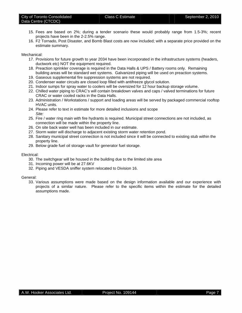
City of Toronto Consolidated Data Centre (CTCDC)
Class C Estimate September 2, 2010
A.W. Hooker Associates Ltd. Project No. 109144 Page 7
15. Fees are based on 2%; during a tender scenario these would probably range from 1.5-3%; recent projects have been in the 2-2.5% range.
16. F2 Tornado, Post Disaster, and Bomb Blast costs are now included; with a separate price provided on the estimate summary.
Mechanical:
17. Provisions for future growth to year 2034 have been incorporated in the infrastructure systems (headers, ductwork etc) NOT the equipment required.
18. Preaction sprinkler coverage is required in the Data Halls & UPS / Battery rooms only. Remaining building areas will be standard wet systems. Galvanized piping will be used on preaction systems.
19. Gaseous supplemental fire suppression systems are not required. 20. Condenser water circuits are closed loop filled with antifreeze glycol solution. 21. Indoor sumps for spray water to coolers will be oversized for 12 hour backup storage volume. 22. Chilled water piping to CRAC’s will contain breakdown valves and caps / valved terminations for future
CRAC or water cooled racks in the Data Halls. 23. Administration / Workstations / support and loading areas will be served by packaged commercial rooftop
HVAC units. 24. Please refer to text in estimate for more detailed inclusions and scope
Site: 25. Fire / water ring main with fire hydrants is required. Municipal street connections are not included, as
connection will be made within the property line. 26. On site back water well has been included in our estimate. 27. Storm water will discharge to adjacent existing storm water retention pond. 28. Sanitary municipal street connection is not included since it will be connected to existing stub within the
property line. 29. Below grade fuel oil storage vault for generator fuel storage.
Electrical:
30. The switchgear will be housed in the building due to the limited site area 31. Incoming power will be at 27.6KV 32. Piping and VESDA sniffer system relocated to Division 16.
General:
33. Various assumptions were made based on the design information available and our experience with projects of a similar nature. Please refer to the specific items within the estimate for the detailed assumptions made.
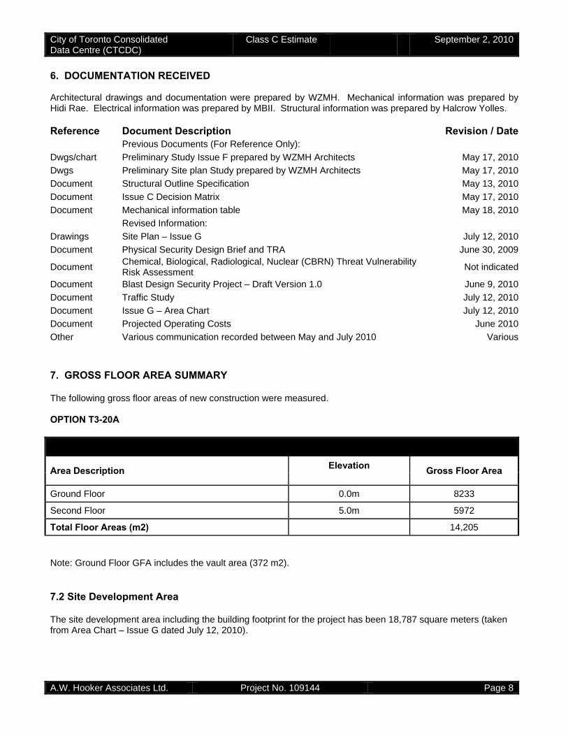
City of Toronto Consolidated Data Centre (CTCDC)
Class C Estimate September 2, 2010
A.W. Hooker Associates Ltd. Project No. 109144 Page 8
6. DOCUMENTATION RECEIVED Architectural drawings and documentation were prepared by WZMH. Mechanical information was prepared by Hidi Rae. Electrical information was prepared by MBII. Structural information was prepared by Halcrow Yolles. Reference Document Description Revision / Date Previous Documents (For Reference Only):
Dwgs/chart Preliminary Study Issue F prepared by WZMH Architects May 17, 2010
Dwgs Preliminary Site plan Study prepared by WZMH Architects May 17, 2010
Document Structural Outline Specification May 13, 2010
Document Issue C Decision Matrix May 17, 2010
Document Mechanical information table May 18, 2010
Revised Information:
Drawings Site Plan – Issue G July 12, 2010
Document Physical Security Design Brief and TRA June 30, 2009
Document Chemical, Biological, Radiological, Nuclear (CBRN) Threat Vulnerability Risk Assessment
Not indicated
Document Blast Design Security Project – Draft Version 1.0 June 9, 2010
Document Traffic Study July 12, 2010
Document Issue G – Area Chart July 12, 2010
Document Projected Operating Costs June 2010
Other Various communication recorded between May and July 2010 Various
7. GROSS FLOOR AREA SUMMARY The following gross floor areas of new construction were measured. OPTION T3-20A
Note: Ground Floor GFA includes the vault area (372 m2). 7.2 Site Development Area The site development area including the building footprint for the project has been 18,787 square meters (taken from Area Chart – Issue G dated July 12, 2010).
AREA TABLE (square meters)
Area Description Elevation Gross Floor Area
Ground Floor 0.0m 8233
Second Floor 5.0m 5972
Total Floor Areas (m2) 14,205

MASTER ESTIMATE SUMMARYCTCDC T3-20ACLASS C ESTIMATESEPTEMBER 02, 2010
GFA Unit Sub Estimated % ofHard Construction Costs (m2) (Cost/m2) Total Total Total
1 Building Shell 14,205 $1,737.80 $24,685,426 20.0%- Sub Structure $284.70 $4,044,110- Structure $657.92 $9,345,721- Exterior Enclosure $795.18 $11,295,596
2 Building Interiors 14,205 $609.44 $8,657,149 7.0%- Partitions and Doors $329.97 $4,687,172- Finishes $81.45 $1,157,035- Fittings and Equipment $198.02 $2,812,942
3 Mechanical 14,205 $1,129.53 $16,045,000 13.0%- Plumbing and Drainage $126.79 $1,801,000- Fire Protection $75.82 $1,077,000- Heating, Ventilation, Air Conditioning $836.96 $11,889,000- Controls $89.97 $1,278,000
4 Electrical 14,205 $2,676.46 $38,019,182 30.8%- Service and Distribution $2,458.40 $34,921,629- Lighting, Devices, and Heating $77.37 $1,098,995- Systems and Ancillaries $140.69 $1,998,557
5 Site Work 14,205 $362.94 $5,155,625 4.2%- Site Development (prep, surfaces, landscaping) $219.77 $3,121,846- Mechanical Site Services $120.73 $1,715,000- Electrical Site Services $22.44 $318,779
6 Ancillary Work 14,205 $0.00 $0 0.0%- Demolition $0.00 $0- Alterations $0.00 $0
$ $7 Contractor's General Requirements 8.0% 14,205 $648.29 $9,209,000 7.5%
8 Contractor's Fees (OH&P) 2.0% 14,205 $143.26 $2,035,000 1.6%
9 Design Contingency 10.0% 14,205 $730.80 $10,381,000 8.4%
Sub Total (current dollars) 14,205 $8,038.51 $114,187,000
10 Escalation Contingency 3.0% 14,205 $241.18 $3,426,000 2.8%
Sub Total (including escalation to 2011 ) 14,205 $8,279.69 $117,613,000
11 Construction Contingency (post contract) 5.0% 14,205 $413.99 $5,880,700 4.8%
Total Estimated Hard Construction Cost 14,205 $8,693.70 $123,494,000
Imperial Conversion 152,903 $807.66 Per SF
Separate Estimates: ( Included Above)
a) Post disaster $853,000
b) F2 Tornado $3,873,000
c) Bomb blast resistance $5,758,000
Separate Estimates: ( Not Included Above)
a) Projected Operating Costs - dated June 2010 $4,834,063
A.W. HOOKER ASSOCIATES LTD. PROJECT NO:109144 PAGE A1
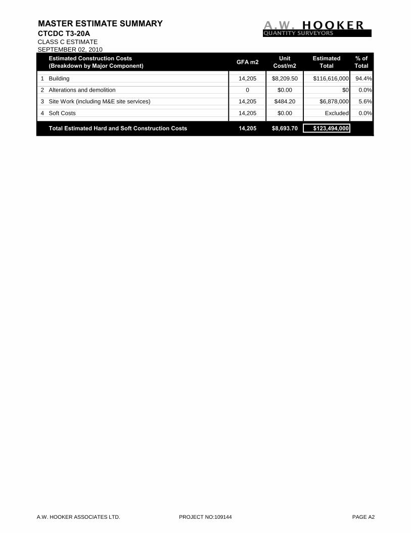
MASTER ESTIMATE SUMMARYCTCDC T3-20ACLASS C ESTIMATESEPTEMBER 02, 2010
Estimated Construction Costs (Breakdown by Major Component) GFA m2 Unit
Cost/m2Estimated
Total% of Total
1 Building 14,205 $8,209.50 $116,616,000 94.4%
2 Alterations and demolition 0 $0.00 $0 0.0%
3 Site Work (including M&E site services) 14,205 $484.20 $6,878,000 5.6%
4 Soft Costs 14,205 $0.00 Excluded 0.0%
Total Estimated Hard and Soft Construction Costs 14,205 $8,693.70 $123,494,000
A.W. HOOKER ASSOCIATES LTD. PROJECT NO:109144 PAGE A2
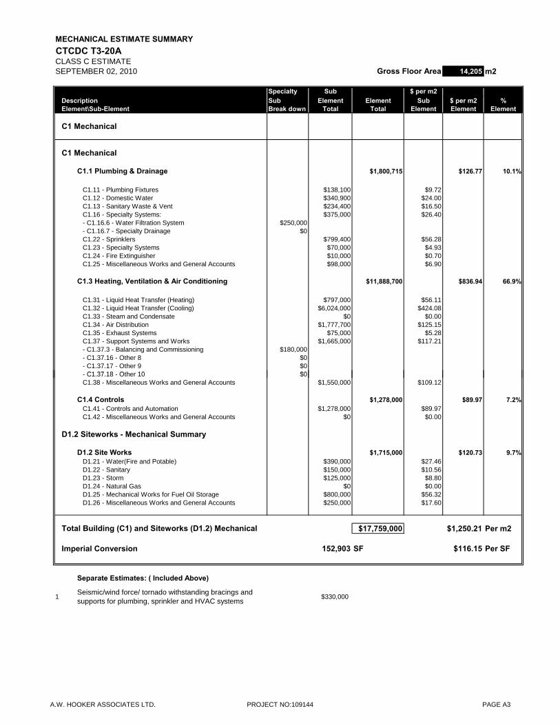
MECHANICAL ESTIMATE SUMMARYCTCDC T3-20ACLASS C ESTIMATESEPTEMBER 02, 2010 Gross Floor Area 14,205 m2
Specialty Sub $ per m2Description Sub Element Element Sub $ per m2 %Element\Sub-Element Break down Total Total Element Element Element
C1 Mechanical
C1 Mechanical
C1.1 Plumbing & Drainage $1,800,715 $126.77 10.1%
C1.11 - Plumbing Fixtures $138,100 $9.72C1.12 - Domestic Water $340,900 $24.00C1.13 - Sanitary Waste & Vent $234,400 $16.50C1.16 - Specialty Systems: $375,000 $26.40- C1.16.6 - Water Filtration System $250,000- C1.16.7 - Specialty Drainage $0C1.22 - Sprinklers $799,400 $56.28C1.23 - Specialty Systems $70,000 $4.93C1.24 - Fire Extinguisher $10,000 $0.70C1.25 - Miscellaneous Works and General Accounts $98,000 $6.90
C1.3 Heating, Ventilation & Air Conditioning $11,888,700 $836.94 66.9%
C1.31 - Liquid Heat Transfer (Heating) $797,000 $56.11C1.32 - Liquid Heat Transfer (Cooling) $6,024,000 $424.08C1.33 - Steam and Condensate $0 $0.00C1.34 - Air Distribution $1,777,700 $125.15C1.35 - Exhaust Systems $75,000 $5.28C1.37 - Support Systems and Works $1,665,000 $117.21- C1.37.3 - Balancing and Commissioning $180,000- C1.37.16 - Other 8 $0- C1.37.17 - Other 9 $0
C1 37 18 Oth 10 $0- C1.37.18 - Other 10 $0C1.38 - Miscellaneous Works and General Accounts $1,550,000 $109.12
C1.4 Controls $1,278,000 $89.97 7.2%C1.41 - Controls and Automation $1,278,000 $89.97C1.42 - Miscellaneous Works and General Accounts $0 $0.00
D1.2 Siteworks - Mechanical Summary
D1.2 Site Works $1,715,000 $120.73 9.7%D1.21 - Water(Fire and Potable) $390,000 $27.46D1.22 - Sanitary $150,000 $10.56D1.23 - Storm $125,000 $8.80D1.24 - Natural Gas $0 $0.00D1.25 - Mechanical Works for Fuel Oil Storage $800,000 $56.32D1.26 - Miscellaneous Works and General Accounts $250,000 $17.60
Total Building (C1) and Siteworks (D1.2) Mechanical $17,759,000 $1,250.21 Per m2
Imperial Conversion 152,903 SF $116.15 Per SF
Separate Estimates: ( Included Above)
1Seismic/wind force/ tornado withstanding bracings and supports for plumbing, sprinkler and HVAC systems
$330,000
A.W. HOOKER ASSOCIATES LTD. PROJECT NO:109144 PAGE A3
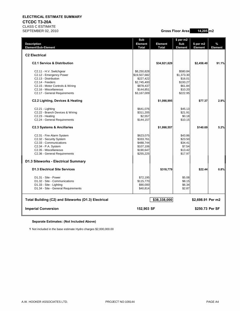
ELECTRICAL ESTIMATE SUMMARYCTCDC T3-20ACLASS C ESTIMATESEPTEMBER 02, 2010 Gross Floor Area 14,205 m2
Sub $ per m2Description Element Element Sub $ per m2 %Element\Sub-Element Total Total Element Element Element
C2 Electrical
C2.1 Service & Distribution $34,921,629 $2,458.40 91.1%
C2.11 - H.V. Switchgear $8,250,828 $580.84C2.12 - Emergency Power $19,507,682 $1,373.30C2.13 - Distribution $227,422 $16.01C2.14 - Feeders $2,745,400 $193.27C2.15 - Motor Controls & Wiring $878,437 $61.84C2.16 - Miscellaneous $144,851 $10.20C2.17 - General Requirements $3,167,009 $222.95
C2.2 Lighting, Devices & Heating $1,098,995 $77.37 2.9%
C2.21 - Lighting $641,076 $45.13C2.22 - Branch Devices & Wiring $311,205 $21.91C2.23 - Heating $2,557 $0.18C2.24 - General Requirements $144,157 $10.15
C2.3 Systems & Ancillaries $1,998,557 $140.69 5.2%
C2.31 - Fire Alarm System $623,075 $43.86C2.32 - Security System $333,761 $23.50C2.33 - Communications $488,744 $34.41C2.34 - P.A. System $107,106 $7.54C2.35 - Miscellaneous $190,647 $13.42C2.36 - General Requirements $255,225 $17.97
D1.3 Siteworks - Electrical Summary
D1.3 Electrical Site Services $318,779 $22.44 0.8%
D1.31 - Site - Power $72,195 $5.08D1.32 - Site - Communications $115,770 $8.15D1.33 - Site - Lighting $90,000 $6.34D1.34 - Site - General Requirements $40,814 $2.87
Total Building (C2) and Siteworks (D1.3) Electrical $38,338,000 $2,698.91 Per m2
Imperial Conversion 152,903 SF $250.73 Per SF
Separate Estimates: (Not Included Above)
1 Not included in the base estimate Hydro charges $2,000,000.00
A.W. HOOKER ASSOCIATES LTD. PROJECT NO:109144 PAGE A4
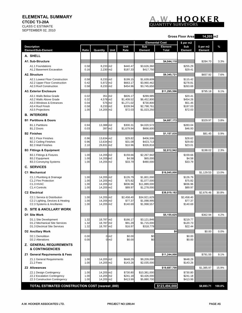
ELEMENTAL SUMMARYCTCDC T3-20ACLASS C ESTIMATESEPTEMBER 02, 2010
Gross Floor Area 14,205 m2
$ per m2Description Unit Sub Element Sub $ per m2 %Element\Sub-Element Ratio Quantity Unit Rate Element Total Element Element
A. SHELLA1. Sub-Structure $4,044,110 $284.70 3.3%
A1.1 Foundations 0.58 8,233 m2 $440.47 $3,626,360 $255.29A1.2 Basement Excavation 0.16 2,230 m2 $187.33 $417,750 $29.41
A2. Structure $9,345,721 $657.92 7.6%
A2.1 Lowest Floor Construction 0.58 8,233 m2 $199.15 $1,639,609 $115.42A2.2 Upper Floor Construction 0.42 5,972 m2 $663.17 $3,960,462 $278.81A2.3 Roof Construction 0.58 8,233 m2 $454.96 $3,745,650 $263.69
A3. Exterior Enclosure $11,295,596 $795.18 9.1%
A3.1 Walls Below Grade 0.02 351 m2 $826.17 $289,985 $20.41A3.2 Walls Above Grade 0.32 4,578 m2 $1,409.52 $6,452,800 $454.26A3.3 Windows & Entrances 0.04 575 m2 $1,271.02 $730,800 $51.45A3.4 Roof Finish 0.58 8,233 m2 $339.94 $2,798,761 $197.03A3.5 Projections 1.00 14,205 m2 $72.03 $1,023,250 $72.03
B. INTERIORSB1 Partitions & Doors $4,687,172 $329.97 3.8%
B1.1 Partitions 0.94 13,388 m2 $300.31 $4,020,572 $283.04B1.2 Doors 0.03 397 m2 $1,679.94 $666,600 $46.93
B2 Finishes $1,157,035 $81.45 0.9%
B2.1 Floor Finishes 0.96 13,634 m2 $29.82 $406,506 $28.62B2.2 Ceiling Finishes 0.96 13,634 m2 $31.08 $423,713 $29.83B2.3 Wall Finishes 2.10 29,831 m2 $10.96 $326,816 $23.01
B3 Fittings & Equipment $2,812,942 $198.02 2.3%
B3.1 Fittings & Fixtures 1.00 14,205 m2 $159.66 $2,267,942 $159.66
Elemental Cost
A.W. HOOKER ASSOCIATES LTD. PROJECT NO:109144 PAGE A5
B3.2 Equipment 1.00 14,205 m2 $4.58 $65,000 $4.58B3.3 Conveying Systems 1.00 14,205 m2 $33.79 $480,000 $33.79
C. SERVICESC1 Mechanical $16,045,000 $1,129.53 13.0%
C1.1 Plumbing & Drainage 1.00 14,205 m2 $126.79 $1,801,000 $126.79C1.2 Fire Protection 1.00 14,205 m2 $75.82 $1,077,000 $75.82C1.3 HVAC 1.00 14,205 m2 $836.96 $11,889,000 $836.96C1.4 Controls 1.00 14,205 m2 $89.97 $1,278,000 $89.97
C2 Electrical $38,019,182 $2,676.46 30.8%
C2.1 Service & Distribution 1.00 14,205 m2 $2,458.40 $34,921,629 $2,458.40C2.2 Lighting, Devices & Heating 1.00 14,205 m2 $77.37 $1,098,995 $77.37C2.3 Systems & Ancillaries 1.00 14,205 m2 $140.69 $1,998,557 $140.69
D. SITE & ANCILLARY WORKD1 Site Work $5,155,625 $362.94 4.2%
D1.1 Site Development 1.32 18,787 m2 $166.17 $3,121,846 $219.77D1.2 Mechanical Site Services 1.32 18,787 m2 $91.29 $1,715,000 $120.73D1.3 Electrical Site Services 1.32 18,787 m2 $16.97 $318,779 $22.44
D2 Ancillary Work $0 $0.00 0.0%
D2.1 Demolition 0.00 0 m2 $0.00 $0 $0.00D2.2 Alterations 0.00 0 m2 $0.00 $0 $0.00
Z. GENERAL REQUIREMENTS & CONTINGENCIES
Z1 General Requirements & Fees $11,244,000 $791.55 9.1%
Z1.1 General Requirements 1.00 14,205 m2 $648.29 $9,209,000 $648.29Z1.2 Fees 1.00 14,205 m2 $143.26 $2,035,000 $143.26
Z2 Allowances $19,687,700 $1,385.97 15.9%
Z2.1 Design Contingency 1.00 14,205 m2 $730.80 $10,381,000 $730.80Z2.2 Escalation Contingency 1.00 14,205 m2 $241.18 $3,426,000 $241.18Z2.3 Construction Contingency 1.00 14,205 m2 $413.99 $5,880,700 $413.99
TOTAL ESTIMATED CONSTRUCTION COST (nearest ,000) $123,494,000 $8,693.71 100.0%
A.W. HOOKER ASSOCIATES LTD. PROJECT NO:109144 PAGE A5
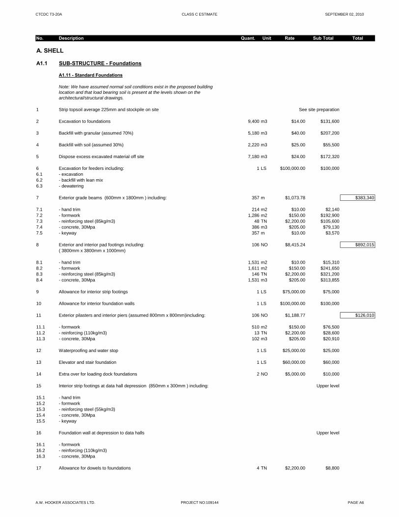
CTCDC T3-20A CLASS C ESTIMATE SEPTEMBER 02, 2010
No. Description Quant. Unit Rate Sub Total Total
A. SHELL
A1.1 SUB-STRUCTURE - Foundations
A1.11 - Standard Foundations
Note: We have assumed normal soil conditions exist in the proposed building location and that load bearing soil is present at the levels shown on the architectural/structural drawings.
1 Strip topsoil average 225mm and stockpile on site See site preparation
2 Excavation to foundations 9,400 m3 $14.00 $131,600
3 Backfill with granular (assumed 70%) 5,180 m3 $40.00 $207,200
4 Backfill with soil (assumed 30%) 2,220 m3 $25.00 $55,500
5 Dispose excess excavated material off site 7,180 m3 $24.00 $172,320
6 Excavation for feeders including: 1 LS $100,000.00 $100,0006.1 - excavation6.2 - backfill with lean mix6.3 - dewatering
7 Exterior grade beams (600mm x 1800mm ) including: 357 m $1,073.78 $383,340
7.1 - hand trim 214 m2 $10.00 $2,1407.2 - formwork 1,286 m2 $150.00 $192,9007.3 - reinforcing steel (85kg/m3) 48 TN $2,200.00 $105,6007.4 - concrete, 30Mpa 386 m3 $205.00 $79,1307.5 - keyway 357 m $10.00 $3,570
8 Exterior and interior pad footings including: 106 NO $8,415.24 $892,015( 3800mm x 3800mm x 1000mm)
8.1 - hand trim 1,531 m2 $10.00 $15,3108.2 - formwork 1,611 m2 $150.00 $241,6508.3 - reinforcing steel (85kg/m3) 146 TN $2,200.00 $321,200g ( g )8.4 - concrete, 30Mpa 1,531 m3 $205.00 $313,855
9 Allowance for interior strip footings 1 LS $75,000.00 $75,000
10 Allowance for interior foundation walls 1 LS $100,000.00 $100,000
11 Exterior pilasters and interior piers (assumed 800mm x 800mm)including: 106 NO $1,188.77 $126,010
11.1 - formwork 510 m2 $150.00 $76,50011.2 - reinforcing (110kg/m3) 13 TN $2,200.00 $28,60011.3 - concrete, 30Mpa 102 m3 $205.00 $20,910
12 Waterproofing and water stop 1 LS $25,000.00 $25,000
13 Elevator and stair foundation 1 LS $60,000.00 $60,000
14 Extra over for loading dock foundations 2 NO $5,000.00 $10,000
15 Interior strip footings at data hall depression (850mm x 300mm ) including: Upper level
15.1 - hand trim15.2 - formwork15.3 - reinforcing steel (55kg/m3)15.4 - concrete, 30Mpa15.5 - keyway
16 Foundation wall at depression to data halls Upper level
16.1 - formwork16.2 - reinforcing (110kg/m3)16.3 - concrete, 30Mpa
17 Allowance for dowels to foundations 4 TN $2,200.00 $8,800
A.W. HOOKER ASSOCIATES LTD. PROJECT NO:109144 PAGE A6
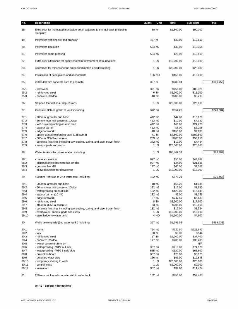
CTCDC T3-20A CLASS C ESTIMATE SEPTEMBER 02, 2010
No. Description Quant. Unit Rate Sub Total Total
18 Extra over for increased foundation depth adjacent to the fuel vault (including stepping)
60 m $1,500.00 $90,000
19 Perimeter weeping tile and granular 437 m $30.00 $13,110
20 Perimeter insulation 524 m2 $35.00 $18,354
21 Perimeter damp proofing 524 m2 $25.00 $13,110
22 Extra over allowance for epoxy coated reinforcement at foundations 1 LS $10,000.00 $10,000
23 Allowance for miscellaneous embedded metals and dewatering 1 LS $25,000.00 $25,000
24 Installation of base plates and anchor bolts 106 NO $150.00 $15,900
25 250 x 450 mm concrete curb to perimeter 357 m $285.04 $101,758
25.1 - formwork 321 m2 $250.00 $80,32525.2 - reinforcing steel 6 TN $2,200.00 $13,20025.3 - concrete, 30Mpa 40 m3 $205.00 $8,233
26 Stepped foundations / depressions 1 LS $25,000.00 $25,000
27 Concrete slab on grade at vault including: 372 m2 $654.26 $243,384
27.1 - 200mm, granular sub base 412 m3 $44.00 $18,12827.2 - 50 mm lean mix concrete, 10Mpa 412 m2 $10.00 $4,12027.3 - WP-1 waterproofing on mud slab 412 m2 $60.00 $24,72027.4 - vapour barrier 412 m2 $8.00 $3,29627.5 - edge formwork 48 m2 $150.00 $7,20027.6 - epoxy coated reinforcing steel (135kg/m3) 41 TN $2,500.00 $102,50027.7 - 600mm, 30MPa concrete 263 m3 $205.00 $53,95627.8 - concrete finishing, including saw cutting, curing, and steel trowel finish 372 m2 $12.00 $4,46427.9 - sumps, pads and curbs 1 LS $25,000.00 $25,000
28 Water tank/chiller pit excavation including: 1 LS $88,469.33 $88,469
28.1 - mass excavation 897 m3 $50.00 $44,86728.2 - disposal of excess materials off site 897 m3 $24.00 $21,53628 3 l b kfill 177 3 $40 00 $7 06728.3 - granular backfill 177 m3 $40.00 $7,06728.4 - allow allowance for dewatering 1 LS $15,000.00 $15,000
29 400 mm Raft slab to 2No water tank including: 132 m2 $579.21 $76,456
29.1 - 200mm, granular sub base 18 m3 $58.25 $1,04929.2 - 50 mm lean mix concrete, 10Mpa 132 m2 $15.00 $1,98029.3 - waterproofing on mud slab 132 m2 $120.00 $15,84029.4 - vapour barrier (10 mil) 132 m2 $8.00 $1,05629.5 - edge formwork 27 m2 $247.50 $6,68329.6 - reinforcing steel 8 TN $2,200.00 $17,60029.7 - 400mm, 30MPa concrete 53 m3 $205.00 $10,86529.8 - concrete finishing, including saw cutting, curing, and steel trowel finish 132 m2 $12.00 $1,58429.9 - overflow pit, sumps, pads and curbs 1 LS $15,000.00 $15,00029.10 - steel ladder to water tank 4 NO $1,200.00 $4,800
30 Walls below grade (2no water tank ) including: 357 m2 $1,399.53 $499,633
30.1 - forms 714 m2 $320.50 $228,83730.2 - key 68 m $8.00 $54430.3 - reinforcing steel 17 TN $2,200.00 $37,40030.4 - concrete, 35Mpa 177 m3 $205.00 $36,28530.5 - winter concrete premium N/A30.6 - waterproofing - WP2 out side 357 m2 $210.00 $74,97030.7 - waterproofing - WP3 inside side 555 m2 $120.00 $66,60030.8 - protection board 357 m2 $25.00 $8,92530.9 - betonies water stop 136 m $93.00 $12,64830.10 - temporary shoring to walls 1 LS $20,000.00 $20,00030.11 - control joints 1 LS $2,000.00 $2,00030.12 - insulation 357 m2 $32.00 $11,424
31 250 mm reinforced concrete slab to water tank 132 m2 $450.00 $59,400
A1.12 - Special Foundations
A.W. HOOKER ASSOCIATES LTD. PROJECT NO:109144 PAGE A7
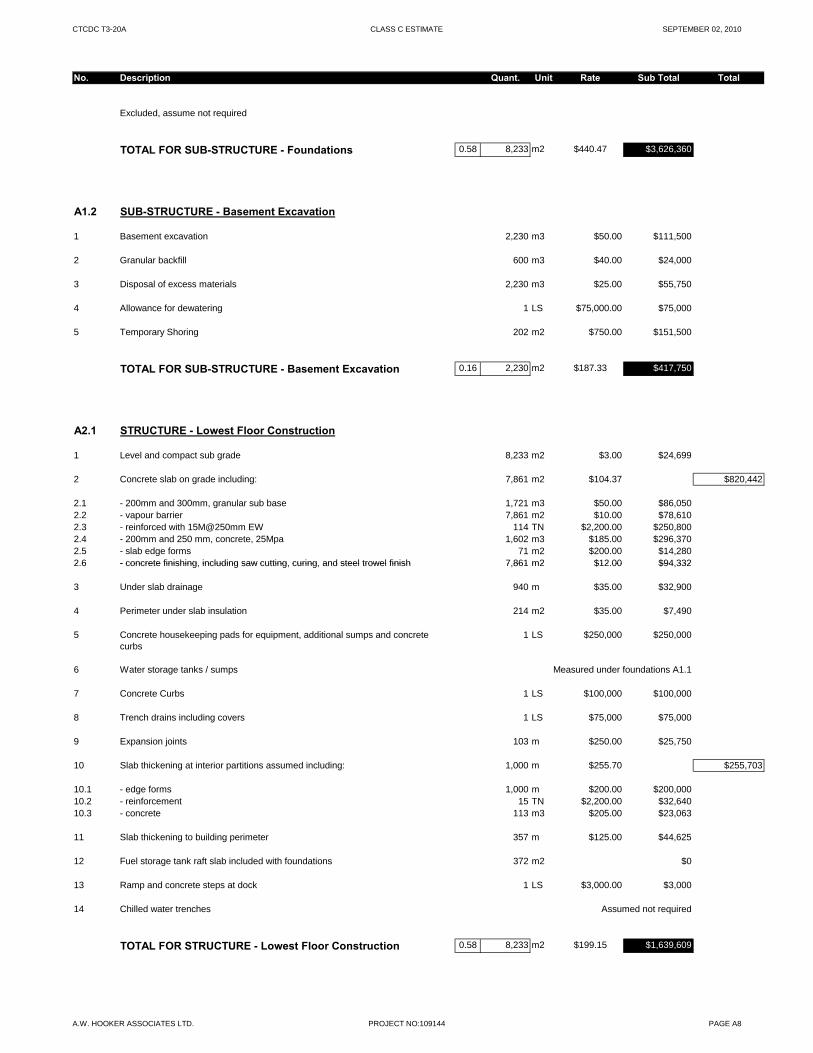
CTCDC T3-20A CLASS C ESTIMATE SEPTEMBER 02, 2010
No. Description Quant. Unit Rate Sub Total Total
Excluded, assume not required
TOTAL FOR SUB-STRUCTURE - Foundations 0.58 8,233 m2 $440.47 $3,626,360
A1.2 SUB-STRUCTURE - Basement Excavation
1 Basement excavation 2,230 m3 $50.00 $111,500
2 Granular backfill 600 m3 $40.00 $24,000
3 Disposal of excess materials 2,230 m3 $25.00 $55,750
4 Allowance for dewatering 1 LS $75,000.00 $75,000
5 Temporary Shoring 202 m2 $750.00 $151,500
TOTAL FOR SUB-STRUCTURE - Basement Excavation 0.16 2,230 m2 $187.33 $417,750
A2.1 STRUCTURE - Lowest Floor Construction
1 Level and compact sub grade 8,233 m2 $3.00 $24,699
2 Concrete slab on grade including: 7,861 m2 $104.37 $820,442
2.1 - 200mm and 300mm, granular sub base 1,721 m3 $50.00 $86,0502.2 - vapour barrier 7,861 m2 $10.00 $78,6102.3 - reinforced with 15M@250mm EW 114 TN $2,200.00 $250,8002.4 - 200mm and 250 mm, concrete, 25Mpa 1,602 m3 $185.00 $296,3702.5 - slab edge forms 71 m2 $200.00 $14,2802 6 - concrete finishing including saw cutting curing and steel trowel finish 7 861 m2 $12 00 $94 3322.6 - concrete finishing, including saw cutting, curing, and steel trowel finish 7,861 m2 $12.00 $94,332
3 Under slab drainage 940 m $35.00 $32,900
4 Perimeter under slab insulation 214 m2 $35.00 $7,490
5 Concrete housekeeping pads for equipment, additional sumps and concrete curbs
1 LS $250,000 $250,000
6 Water storage tanks / sumps Measured under foundations A1.1
7 Concrete Curbs 1 LS $100,000 $100,000
8 Trench drains including covers 1 LS $75,000 $75,000
9 Expansion joints 103 m $250.00 $25,750
10 Slab thickening at interior partitions assumed including: 1,000 m $255.70 $255,703
10.1 - edge forms 1,000 m $200.00 $200,00010.2 - reinforcement 15 TN $2,200.00 $32,64010.3 - concrete 113 m3 $205.00 $23,063
11 Slab thickening to building perimeter 357 m $125.00 $44,625
12 Fuel storage tank raft slab included with foundations 372 m2 $0
13 Ramp and concrete steps at dock 1 LS $3,000.00 $3,000
14 Chilled water trenches Assumed not required
TOTAL FOR STRUCTURE - Lowest Floor Construction 0.58 8,233 m2 $199.15 $1,639,609
A.W. HOOKER ASSOCIATES LTD. PROJECT NO:109144 PAGE A8
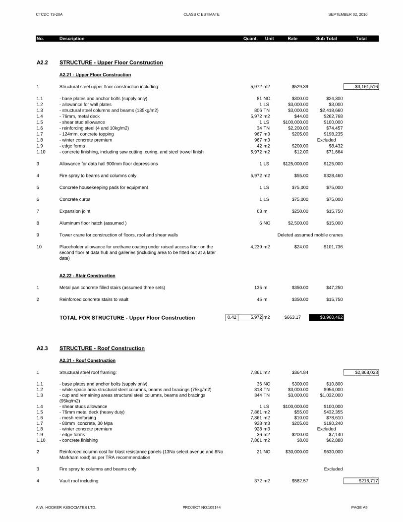
CTCDC T3-20A CLASS C ESTIMATE SEPTEMBER 02, 2010
No. Description Quant. Unit Rate Sub Total Total
A2.2 STRUCTURE - Upper Floor Construction
A2.21 - Upper Floor Construction
1 Structural steel upper floor construction including: 5,972 m2 $529.39 $3,161,516
1.1 - base plates and anchor bolts (supply only) 81 NO $300.00 $24,3001.2 - allowance for wall plates 1 LS $3,000.00 $3,0001.3 - structural steel columns and beams (135kg/m2) 806 TN $3,000.00 $2,418,6601.4 - 76mm, metal deck 5,972 m2 $44.00 $262,7681.5 - shear stud allowance 1 LS $100,000.00 $100,0001.6 - reinforcing steel (4 and 10kg/m2) 34 TN $2,200.00 $74,4571.7 - 124mm, concrete topping 967 m3 $205.00 $198,2351.8 - winter concrete premium 967 m3 Excluded1.9 - edge forms 42 m2 $200.00 $8,4321.10 - concrete finishing, including saw cutting, curing, and steel trowel finish 5,972 m2 $12.00 $71,664
3 Allowance for data hall 900mm floor depressions 1 LS $125,000.00 $125,000
4 Fire spray to beams and columns only 5,972 m2 $55.00 $328,460
5 Concrete housekeeping pads for equipment 1 LS $75,000 $75,000
6 Concrete curbs 1 LS $75,000 $75,000
7 Expansion joint 63 m $250.00 $15,750
8 Aluminum floor hatch (assumed ) 6 NO $2,500.00 $15,000
9 Tower crane for construction of floors, roof and shear walls Deleted assumed mobile cranes
10 Placeholder allowance for urethane coating under raised access floor on the second floor at data hub and galleries (including area to be fitted out at a later date)
4,239 m2 $24.00 $101,736
A2.22 - Stair Construction
1 Metal pan concrete filled stairs (assumed three sets) 135 m $350.00 $47,250
2 Reinforced concrete stairs to vault 45 m $350.00 $15,750
TOTAL FOR STRUCTURE - Upper Floor Construction 0.42 5,972 m2 $663.17 $3,960,462
A2.3 STRUCTURE - Roof Construction
A2.31 - Roof Construction
1 Structural steel roof framing: 7,861 m2 $364.84 $2,868,033
1.1 - base plates and anchor bolts (supply only) 36 NO $300.00 $10,8001.2 - white space area structural steel columns, beams and bracings (75kg/m2) 318 TN $3,000.00 $954,0001.3 - cup and remaining areas structural steel columns, beams and bracings
(95kg/m2)344 TN $3,000.00 $1,032,000
1.4 - shear studs allowance 1 LS $100,000.00 $100,0001.5 - 76mm metal deck (heavy duty) 7,861 m2 $55.00 $432,3551.6 - mesh reinforcing 7,861 m2 $10.00 $78,6101.7 - 80mm concrete, 30 Mpa 928 m3 $205.00 $190,2401.8 - winter concrete premium 928 m3 Excluded1.9 - edge forms 36 m2 $200.00 $7,1401.10 - concrete finishing 7,861 m2 $8.00 $62,888
2 Reinforced column cost for blast resistance panels (13No select avenue and 8No Markham road) as per TRA recommendation
21 NO $30,000.00 $630,000
3 Fire spray to columns and beams only Excluded
4 Vault roof including: 372 m2 $582.57 $216,717
A.W. HOOKER ASSOCIATES LTD. PROJECT NO:109144 PAGE A9

CTCDC T3-20A CLASS C ESTIMATE SEPTEMBER 02, 2010
No. Description Quant. Unit Rate Sub Total Total
4.1 - column forms 90 m2 $135.00 $12,1504.2 - beam forms 132 m2 $130.00 $17,1604.3 - slab edge forms 24 m2 $200.00 $4,8004.4 - soffit forms 372 m2 $150.00 $55,8004.5 - reinforcing steel (135kg/m3) 18 TN $2,200.00 $39,6004.6 - 350mm, concrete slab 130 m3 $205.00 $26,6914.7 - winter concrete premium 130 m3 Excluded4.8 - screed and cure 372 m2 $4.00 $1,4884.9 - steel trowel finish 372 m2 $4.00 $1,4884.10 - prestressed concrete panels 100 m2 $280.00 $28,0004.11 - 100 mm concrete topping 372 m2 $25.00 $9,3004.12 - waterproofing 372 m2 $45.00 $16,7404.13 - roof curb 14 m $250.00 $3,500
5 Roof expansion joint 103 m $300.00 $30,900
TOTAL FOR STRUCTURE - Roof Construction 0.58 8,233 m2 $454.96 $3,745,650
A3.1 EXTERIOR ENCLOSURE - Walls Below Grade
A3.11 - Walls Below Grade
1 Vault walls below grade including: 351 m2 $826.17 $289,985
1.1 - forms 702 m2 $250.00 $175,5001.2 - key 80 m $8.00 $6401.3 - epoxy coated reinforcing steel (105kg/m3) 11 TN $2,500.00 $27,5001.4 - 300mm, concrete, 30Mpa 105 m3 $205.00 $21,5251.5 - winter concrete premium 105 m3 $16.00 $1,6801.6 - waterproofing 351 m2 $85.00 $29,8351.7 - protection board 351 m2 $25.00 $8,7751.8 - bentonite water stop 80 m $150.00 $12,0001.9 - control joints 1 LS $2,000.00 $2,0001.10 - insulation 351 m2 $30.00 $10,530$ $ ,
A3.12 - Structural Walls Below Grade
NIL
TOTAL FOR EXT. ENCLOSURE - Walls Below Grade 0.02 351 m2 $826.17 $289,985
A3.2 EXTERIOR ENCLOSURE - Walls Above Grade
A3.21 - Walls Above Grade
1 Architectural sand blasted precast concrete insulated sandwich panels (bomb blast) including:
3,428 m2 $775.00 $2,656,700
1.1 - 75 mm outer precast panel1.2 - 13mm air space1.3 - 75 mm rigid insulation1.4 - 200 mm inner precast panel
2 Extra over for 300mm precast concrete bands 1 LS $50,000.00 $50,000
3 Expansion joint 22 m $150.00 $3,300
4 Plenum wall construction (assumed at exhaust) 850 m2 $1,130.00 $960,500
4.1 - metal panels on z-girts (sobertec or similar standard product) 850 m2 $425.00 $361,2504.2 - air space 850 m2 $0.00 $04.3 - 75mm insulation 850 m2 $30.00 $25,5004.4 - self adhering AVB 850 m2 $25.00 $21,2504.5 - 250mm precast panel 850 m2 $650.00 $552,500
A.W. HOOKER ASSOCIATES LTD. PROJECT NO:109144 PAGE A10
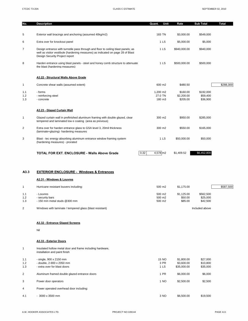
CTCDC T3-20A CLASS C ESTIMATE SEPTEMBER 02, 2010
No. Description Quant. Unit Rate Sub Total Total
5 Exterior wall bracings and anchoring (assumed 40kg/m2) 183 TN $3,000.00 $549,000
6 Extra over for knockout panel 1 LS $5,000.00 $5,000
7 Design entrance with turnstile pass through and floor to ceiling blast panels; as well as visitor vestibule (hardening measures) as indicated on page 28 of Blast Design Security Project report
1 LS $940,000.00 $940,000
8 Harden entrance using blast panels - steel and honey comb structure to attenuate the blast (hardening measures)
1 LS $500,000.00 $500,000
A3.22 - Structural Walls Above Grade
1 Concrete shear walls (assumed extent) 600 m2 $480.50 $288,300
1.1 - forms 1,200 m2 $160.00 $192,0001.2 - reinforcing steel 27.0 TN $2,200.00 $59,4001.3 - concrete 180 m3 $205.00 $36,900
A3.23 - Glazed Curtain Wall
1 Glazed curtain wall in prefinished aluminum framing with double glazed, clear tempered and laminated low e coating (area as previous)
300 m2 $950.00 $285,000
2 Extra over for harden entrance glass to GSA level 3, 20mil thickness (laminate+glazing)- hardening measures
300 m2 $550.00 $165,000
3 Blast - tec energy absorbing aluminum entrance window framing system (hardening measures) - prorated
1 LS $50,000.00 $50,000
TOTAL FOR EXT. ENCLOSURE - Walls Above Grade 0.32 4,578 m2 $1,409.52 $6,452,800
A3 3 EXTERIOR ENCLOSURE - Windows & EntrancesA3.3 EXTERIOR ENCLOSURE - Windows & Entrances
A3.31 - Windows & Louvres
1 Hurricane resistant louvers including: 500 m2 $1,175.00 $587,500
1.1 - Louvres 500 m2 $1,125.00 $562,5001.2 - security bars 500 m2 $50.00 $25,0001.3 - 150 mm metal studs @300 mm 500 m2 $85.00 $42,500
2 Windows with laminate / tempered glass (blast resistant) Included above
A3.32 - Entrance Glazed Screens
Nil
A3.33 - Exterior Doors
1 Insulated hollow metal door and frame including hardware, installation and paint finish
1.1 - single, 900 x 2150 mm 15 NO $1,800.00 $27,0001.2 - double, 2-900 x 2050 mm 3 PR $3,600.00 $10,8001.3 - extra over for blast doors 1 LS $35,000.00 $35,000
2 Aluminum framed double glazed entrance doors 1 PR $6,000.00 $6,000
3 Power door operators 1 NO $2,500.00 $2,500
4 Power operated overhead door including:
4.1 - 3000 x 3500 mm 3 NO $6,500.00 $19,500
A.W. HOOKER ASSOCIATES LTD. PROJECT NO:109144 PAGE A11
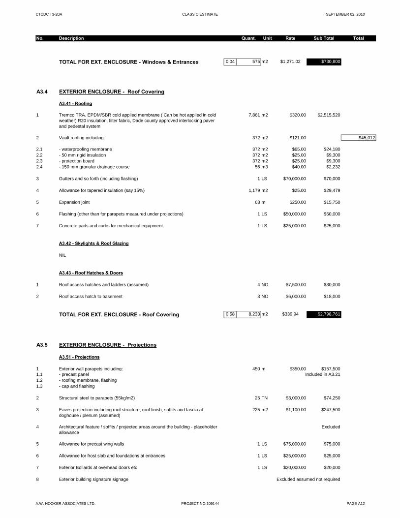
CTCDC T3-20A CLASS C ESTIMATE SEPTEMBER 02, 2010
No. Description Quant. Unit Rate Sub Total Total
TOTAL FOR EXT. ENCLOSURE - Windows & Entrances 0.04 575 m2 $1,271.02 $730,800
A3.4 EXTERIOR ENCLOSURE - Roof Covering
A3.41 - Roofing
1 Tremco TRA. EPDM/SBR cold applied membrane ( Can be hot applied in cold weather) R20 insulation, filter fabric, Dade county approved interlocking paver and pedestal system
7,861 m2 $320.00 $2,515,520
2 Vault roofing including: 372 m2 $121.00 $45,012
2.1 - waterproofing membrane 372 m2 $65.00 $24,1802.2 - 50 mm rigid insulation 372 m2 $25.00 $9,3002.3 - protection board 372 m2 $25.00 $9,3002.4 - 150 mm granular drainage course 56 m3 $40.00 $2,232
3 Gutters and so forth (including flashing) 1 LS $70,000.00 $70,000
4 Allowance for tapered insulation (say 15%) 1,179 m2 $25.00 $29,479
5 Expansion joint 63 m $250.00 $15,750
6 Flashing (other than for parapets measured under projections) 1 LS $50,000.00 $50,000
7 Concrete pads and curbs for mechanical equipment 1 LS $25,000.00 $25,000
A3.42 - Skylights & Roof Glazing
NIL
A3.43 - Roof Hatches & Doors
1 Roof access hatches and ladders (assumed) 4 NO $7,500.00 $30,000
2 Roof access hatch to basement 3 NO $6,000.00 $18,000
TOTAL FOR EXT. ENCLOSURE - Roof Covering 0.58 8,233 m2 $339.94 $2,798,761
A3.5 EXTERIOR ENCLOSURE - Projections
A3.51 - Projections
1 Exterior wall parapets including: 450 m $350.00 $157,5001.1 - precast panel Included in A3.211.2 - roofing membrane, flashing1.3 - cap and flashing
2 Structural steel to parapets (55kg/m2) 25 TN $3,000.00 $74,250
3 Eaves projection including roof structure, roof finish, soffits and fascia at doghouse / plenum (assumed)
225 m2 $1,100.00 $247,500
4 Architectural feature / soffits / projected areas around the building - placeholder allowance
Excluded
5 Allowance for precast wing walls 1 LS $75,000.00 $75,000
6 Allowance for frost slab and foundations at entrances 1 LS $25,000.00 $25,000
7 Exterior Bollards at overhead doors etc 1 LS $20,000.00 $20,000
8 Exterior building signature signage Excluded assumed not required
A.W. HOOKER ASSOCIATES LTD. PROJECT NO:109144 PAGE A12
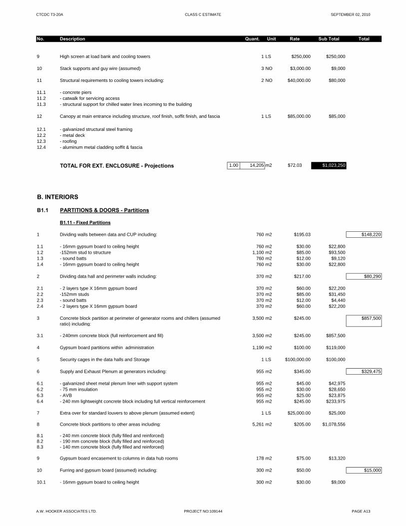
CTCDC T3-20A CLASS C ESTIMATE SEPTEMBER 02, 2010
No. Description Quant. Unit Rate Sub Total Total
9 High screen at load bank and cooling towers 1 LS $250,000 $250,000
10 Stack supports and guy wire (assumed) 3 NO $3,000.00 $9,000
11 Structural requirements to cooling towers including: 2 NO $40,000.00 $80,000
11.1 - concrete piers11.2 - catwalk for servicing access11.3 - structural support for chilled water lines incoming to the building
12 Canopy at main entrance including structure, roof finish, soffit finish, and fascia 1 LS $85,000.00 $85,000
12.1 - galvanized structural steel framing12.2 - metal deck12.3 - roofing12.4 - aluminum metal cladding soffit & fascia
TOTAL FOR EXT. ENCLOSURE - Projections 1.00 14,205 m2 $72.03 $1,023,250
B. INTERIORS
B1.1 PARTITIONS & DOORS - Partitions
B1.11 - Fixed Partitions
1 Dividing walls between data and CUP including: 760 m2 $195.03 $148,220
1.1 - 16mm gypsum board to ceiling height 760 m2 $30.00 $22,8001.2 -152mm stud to structure 1,100 m2 $85.00 $93,5001.3 - sound batts 760 m2 $12.00 $9,1201.4 - 16mm gypsum board to ceiling height 760 m2 $30.00 $22,800
2 Dividing data hall and perimeter walls including: 370 m2 $217.00 $80,290
2.1 - 2 layers type X 16mm gypsum board 370 m2 $60.00 $22,2002.2 -152mm studs 370 m2 $85.00 $31,4502.3 - sound batts 370 m2 $12.00 $4,4402.4 - 2 layers type X 16mm gypsum board 370 m2 $60.00 $22,200
3 Concrete block partition at perimeter of generator rooms and chillers (assumed ratio) including:
3,500 m2 $245.00 $857,500
3.1 - 240mm concrete block (full reinforcement and fill) 3,500 m2 $245.00 $857,500
4 Gypsum board partitions within administration 1,190 m2 $100.00 $119,000
5 Security cages in the data halls and Storage 1 LS $100,000.00 $100,000
6 Supply and Exhaust Plenum at generators including: 955 m2 $345.00 $329,475
6.1 - galvanized sheet metal plenum liner with support system 955 m2 $45.00 $42,9756.2 - 75 mm insulation 955 m2 $30.00 $28,6506.3 - AVB 955 m2 $25.00 $23,8756.4 - 240 mm lightweight concrete block including full vertical reinforcement 955 m2 $245.00 $233,975
7 Extra over for standard louvers to above plenum (assumed extent) 1 LS $25,000.00 $25,000
8 Concrete block partitions to other areas including: 5,261 m2 $205.00 $1,078,556
8.1 - 240 mm concrete block (fully filled and reinforced)8.2 - 190 mm concrete block (fully filled and reinforced)8.3 - 140 mm concrete block (fully filled and reinforced)
9 Gypsum board encasement to columns in data hub rooms 178 m2 $75.00 $13,320
10 Furring and gypsum board (assumed) including: 300 m2 $50.00 $15,000
10.1 - 16mm gypsum board to ceiling height 300 m2 $30.00 $9,000
A.W. HOOKER ASSOCIATES LTD. PROJECT NO:109144 PAGE A13
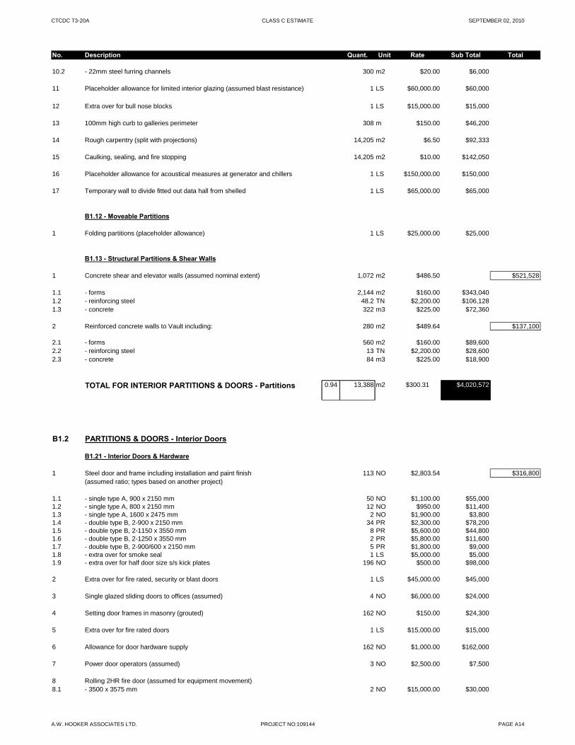
CTCDC T3-20A CLASS C ESTIMATE SEPTEMBER 02, 2010
No. Description Quant. Unit Rate Sub Total Total
10.2 - 22mm steel furring channels 300 m2 $20.00 $6,000
11 Placeholder allowance for limited interior glazing (assumed blast resistance) 1 LS $60,000.00 $60,000
12 Extra over for bull nose blocks 1 LS $15,000.00 $15,000
13 100mm high curb to galleries perimeter 308 m $150.00 $46,200
14 Rough carpentry (split with projections) 14,205 m2 $6.50 $92,333
15 Caulking, sealing, and fire stopping 14,205 m2 $10.00 $142,050
16 Placeholder allowance for acoustical measures at generator and chillers 1 LS $150,000.00 $150,000
17 Temporary wall to divide fitted out data hall from shelled 1 LS $65,000.00 $65,000
B1.12 - Moveable Partitions
1 Folding partitions (placeholder allowance) 1 LS $25,000.00 $25,000
B1.13 - Structural Partitions & Shear Walls
1 Concrete shear and elevator walls (assumed nominal extent) 1,072 m2 $486.50 $521,528
1.1 - forms 2,144 m2 $160.00 $343,0401.2 - reinforcing steel 48.2 TN $2,200.00 $106,1281.3 - concrete 322 m3 $225.00 $72,360
2 Reinforced concrete walls to Vault including: 280 m2 $489.64 $137,100
2.1 - forms 560 m2 $160.00 $89,6002.2 - reinforcing steel 13 TN $2,200.00 $28,6002.3 - concrete 84 m3 $225.00 $18,900
TOTAL FOR INTERIOR PARTITIONS & DOORS - Partitions 0.94 13,388 m2 $300.31 $4,020,572
B1.2 PARTITIONS & DOORS - Interior Doors
B1.21 - Interior Doors & Hardware
1 Steel door and frame including installation and paint finish 113 NO $2,803.54 $316,800(assumed ratio; types based on another project)
1.1 - single type A, 900 x 2150 mm 50 NO $1,100.00 $55,0001.2 - single type A, 800 x 2150 mm 12 NO $950.00 $11,4001.3 - single type A, 1600 x 2475 mm 2 NO $1,900.00 $3,8001.4 - double type B, 2-900 x 2150 mm 34 PR $2,300.00 $78,2001.5 - double type B, 2-1150 x 3550 mm 8 PR $5,600.00 $44,8001.6 - double type B, 2-1250 x 3550 mm 2 PR $5,800.00 $11,6001.7 - double type B, 2-900/600 x 2150 mm 5 PR $1,800.00 $9,0001.8 - extra over for smoke seal 1 LS $5,000.00 $5,0001.9 - extra over for half door size s/s kick plates 196 NO $500.00 $98,000
2 Extra over for fire rated, security or blast doors 1 LS $45,000.00 $45,000
3 Single glazed sliding doors to offices (assumed) 4 NO $6,000.00 $24,000
4 Setting door frames in masonry (grouted) 162 NO $150.00 $24,300
5 Extra over for fire rated doors 1 LS $15,000.00 $15,000
6 Allowance for door hardware supply 162 NO $1,000.00 $162,000
7 Power door operators (assumed) 3 NO $2,500.00 $7,500
8 Rolling 2HR fire door (assumed for equipment movement)8.1 - 3500 x 3575 mm 2 NO $15,000.00 $30,000
A.W. HOOKER ASSOCIATES LTD. PROJECT NO:109144 PAGE A14

CTCDC T3-20A CLASS C ESTIMATE SEPTEMBER 02, 2010
No. Description Quant. Unit Rate Sub Total Total
8.2 - 2200 x 3575 mm 1 NO $12,000.00 $12,000
9 View panels and transoms 1 LS $25,000.00 $25,000
10 Extra over allowance for solid core wood doors at office areas 1 LS $5,000.00 $5,000
TOTAL FOR INTERIOR PARTITIONS & DOORS - Doors 0.03 397 m2 $1,679.94 $666,600
B2.1 FINISHES - Floor Finishes
B2.11 - Floor Finishes
1 Special Flooring (Electrical UPS Rooms, Mechanical UPS Rooms and battery), concrete sealer as per basis of design, (assumed Trowel applied high build Epoxy or similar)
1,998 m2 $95.00 $189,850
2 Special Flooring (to diesel tank building), Trowel applied high build Epoxy or similar
353 m2 $95.00 $33,573
3 Shake on concrete hardener to loading dock, including receiving area 564 m2 $12.00 $6,772
4 Concrete sealer to mechanical and electrical rooms (non UPS rooms) (Ashford formula)
4,663 m2 $2.75 $12,823
5 Concrete sealer to underside of raised access floor including: (Ashford formula)
5.1 - data hub rooms and mechanical galleries 1,742 m2 $2.75 $4,7915.2 - future data hub/ mechanical galleries- fit out 2,497 m2 $2.75 $6,8675.3 - corridor surrounded data hubs and mechanical galleries 190 m2 $2.75 $523
6 Porcelain tile to washrooms/change rooms 213 m2 $150.00 $31,920
7 Carpet tile to administration area 906 m2 $45.00 $40,784
8 R ili t fl i t it t d id 506 2 $60 00 $30 3818 Resilient flooring to security rooms, support rooms and corridors 506 m2 $60.00 $30,381
9 Flooring bases including:9.1 - resilient cove 4,370 m $8.00 $34,9629.2 - resilient cove at UPS and battery room 385 m $20.00 $7,7009.3 - resilient cove at UPS (future) 352 m Unfinished9.4 - porcelain tile 132 m $18.00 $2,3769.5 - epoxy 177 m $18.00 $3,1869.6 - future data hub/ gallery fit-out 188 m Unfinished
TOTAL FOR FINISHES - Floor Finishes 0.96 13,634 m2 $29.82 $406,506
B2.2 FINISHES - Ceiling Finishes
B2.21 - Ceiling Finishes
1 Spray painted (assumed 2 coats) exposed metal structure1.1 - to diesel tank, assumed with epoxy finish 353 m2 $45.00 $15,9031.2 - to mechanical room, loading dock and mechanical gallery 6,851 m2 $9.00 $61,663
2 Insulation mechanically fastened to the under side of the structure with a white facing (loading dock, and handling and receiving)
564 m2 $35.00 $19,751
3 Gypsum board to washroom and shower, moisture resistant 213 m2 $110.00 $23,408
4 Placeholder allowance for fire rated gypsum board with paint finish to corridors 1 LS $75,000.00 $75,000
5 24" x 48" x 5/8" acoustic ceiling tile in aluminum grid including: 5.1 - clean room clima plus to data hub room 1,742 m2 $65.00 $113,230
A.W. HOOKER ASSOCIATES LTD. PROJECT NO:109144 PAGE A15
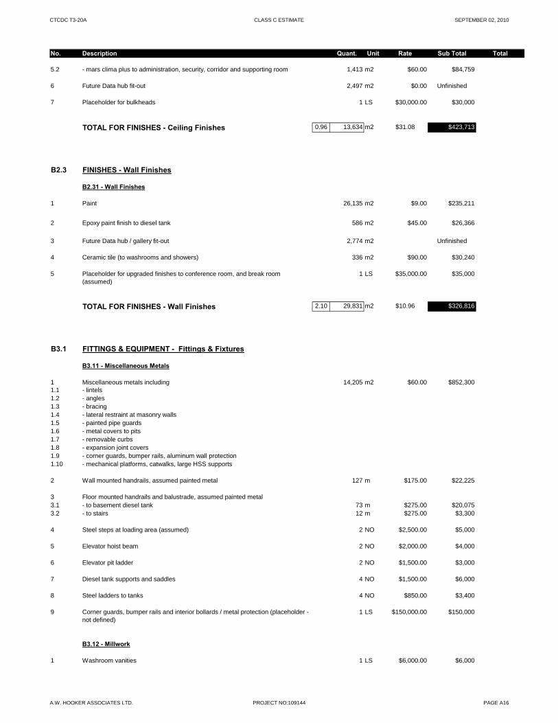
CTCDC T3-20A CLASS C ESTIMATE SEPTEMBER 02, 2010
No. Description Quant. Unit Rate Sub Total Total
5.2 - mars clima plus to administration, security, corridor and supporting room 1,413 m2 $60.00 $84,759
6 Future Data hub fit-out 2,497 m2 $0.00 Unfinished
7 Placeholder for bulkheads 1 LS $30,000.00 $30,000
TOTAL FOR FINISHES - Ceiling Finishes 0.96 13,634 m2 $31.08 $423,713
B2.3 FINISHES - Wall Finishes
B2.31 - Wall Finishes
1 Paint 26,135 m2 $9.00 $235,211
2 Epoxy paint finish to diesel tank 586 m2 $45.00 $26,366
3 Future Data hub / gallery fit-out 2,774 m2 Unfinished
4 Ceramic tile (to washrooms and showers) 336 m2 $90.00 $30,240
5 Placeholder for upgraded finishes to conference room, and break room (assumed)
1 LS $35,000.00 $35,000
TOTAL FOR FINISHES - Wall Finishes 2.10 29,831 m2 $10.96 $326,816
B3.1 FITTINGS & EQUIPMENT - Fittings & Fixtures
B3.11 - Miscellaneous Metals
1 Miscellaneous metals including 14,205 m2 $60.00 $852,3001.1 - lintels1.2 - angles1.3 - bracing1.4 - lateral restraint at masonry walls1.5 - painted pipe guards 1.6 - metal covers to pits1.7 - removable curbs1.8 - expansion joint covers1.9 - corner guards, bumper rails, aluminum wall protection1.10 - mechanical platforms, catwalks, large HSS supports
2 Wall mounted handrails, assumed painted metal 127 m $175.00 $22,225
3 Floor mounted handrails and balustrade, assumed painted metal3.1 - to basement diesel tank 73 m $275.00 $20,0753.2 - to stairs 12 m $275.00 $3,300
4 Steel steps at loading area (assumed) 2 NO $2,500.00 $5,000
5 Elevator hoist beam 2 NO $2,000.00 $4,000
6 Elevator pit ladder 2 NO $1,500.00 $3,000
7 Diesel tank supports and saddles 4 NO $1,500.00 $6,000
8 Steel ladders to tanks 4 NO $850.00 $3,400
9 Corner guards, bumper rails and interior bollards / metal protection (placeholder - not defined)
1 LS $150,000.00 $150,000
B3.12 - Millwork
1 Washroom vanities 1 LS $6,000.00 $6,000
A.W. HOOKER ASSOCIATES LTD. PROJECT NO:109144 PAGE A16
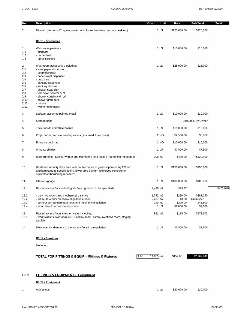
CTCDC T3-20A CLASS C ESTIMATE SEPTEMBER 02, 2010
No. Description Quant. Unit Rate Sub Total Total
2 Millwork (kitchens, IT space, workshops, locker benches, security desk etc) 1 LS $125,000.00 $125,000
B3.13 - Specialties
1 Washroom partitions 1 LS $10,000.00 $10,0001.1 - standard1.2 - barrier free1.3 - urinal screens
2 Washroom accessories including: 1 LS $25,000.00 $25,0002.1 - toilet paper dispenser2.2 - soap dispenser2.3 - paper towel dispenser2.4 - grab bars 2.5 - sanitary dispenser2.6 - sanitary disposal2.7 - shower soap dish2.8 - fold down shower seat 2.9 - shower curtain and rod2.10 - shower grab bars2.11 - mirrors2.12 - waste receptacles
3 Lockers, assumed painted metal 1 LS $10,000.00 $10,000
4 Storage units Excluded, By Owner
5 Tack boards and white boards 1 LS $15,000.00 $15,000
6 Projection screens to meeting rooms (assumed 1 per room) 2 NO $2,500.00 $5,000
7 Entrance pedimat 1 NO $10,000.00 $10,000
8 Window shades 1 LS $7,500.00 $7,500
9 Blast curtains - Select Avenue and Markham Road facade (hardening measures) 300 m2 $430.00 $129,000
10 Hardened security desk area with double panes of glass separated by 120mm 1 LS $150,000.00 $150,000and laminated to specifications, lower area 300mm reinforced concrete or equivalent (hardening measures)
11 Interior signage 1 LS $100,000.00 $100,000
12 Raised access floor including tile finish (product to be specified) 4,429 m2 $95.97 $425,040
12.1 - data hub rooms and mechanical galleries 1,742 m2 $220.00 $383,24012.2 - future data hub/ mechanical galleries- fit out 2,497 m2 $0.00 Unfinished12.3 - corridor surrounded data hubs and mechanical galleries 190 m2 $220.00 $41,80012.4 - wood stair to access future space 1 LS $2,000.00 $2,000
13 Raised access floors to other areas including: 981 m2 $175.00 $171,60213.1 - work stations, war room, NOC, control room, communications room, staging,
test lab
14 Extra over for dampers to the access floor in the galleries 1 LS $7,500.00 $7,500
B3.14 - Furniture
Excluded
TOTAL FOR FITTINGS & EQUIP. - Fittings & Fixtures 1.00 14,205 m2 $159.66 $2,267,942
B3.2 FITTINGS & EQUIPMENT - Equipment
B3.21 - Equipment
1 Appliances 1 LS $20,000.00 $20,000
A.W. HOOKER ASSOCIATES LTD. PROJECT NO:109144 PAGE A17
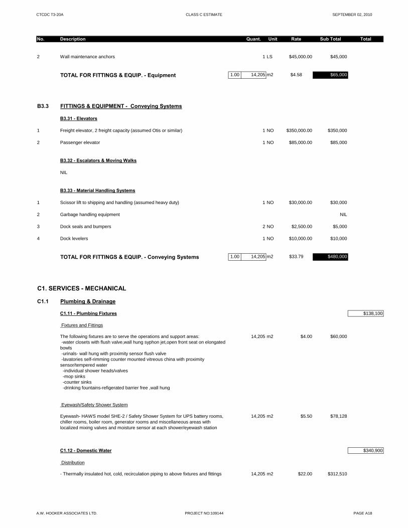
CTCDC T3-20A CLASS C ESTIMATE SEPTEMBER 02, 2010
No. Description Quant. Unit Rate Sub Total Total
2 Wall maintenance anchors 1 LS $45,000.00 $45,000
TOTAL FOR FITTINGS & EQUIP. - Equipment 1.00 14,205 m2 $4.58 $65,000
B3.3 FITTINGS & EQUIPMENT - Conveying Systems
B3.31 - Elevators
1 Freight elevator, 2 freight capacity (assumed Otis or similar) 1 NO $350,000.00 $350,000
2 Passenger elevator 1 NO $85,000.00 $85,000
B3.32 - Escalators & Moving Walks
NIL
B3.33 - Material Handling Systems
1 Scissor lift to shipping and handling (assumed heavy duty) 1 NO $30,000.00 $30,000
2 Garbage handling equipment NIL
3 Dock seals and bumpers 2 NO $2,500.00 $5,000
4 Dock levelers 1 NO $10,000.00 $10,000
TOTAL FOR FITTINGS & EQUIP. - Conveying Systems 1.00 14,205 m2 $33.79 $480,000
C1. SERVICES - MECHANICAL
C1.1 Plumbing & Drainage
C1.11 - Plumbing Fixtures $138,100
Fixtures and Fittings
The following fixtures are to serve the operations and support areas: 14,205 m2 $4.00 $60,000 -water closets with flush valve,wall hung syphon jet,open front seat on elongated bowls -urinals- wall hung with proximity sensor flush valve -lavatories self-rimming counter mounted vitreous china with proximity sensor/tempered water -individual shower heads/valves -mop sinks -counter sinks -drinking fountains-refigerated barrier free ,wall hung
Eyewash/Safety Shower System
Eyewash- HAWS model SHE-2 / Safety Shower System for UPS battery rooms, chiller rooms, boiler room, generator rooms and miscellaneous areas with localized mixing valves and moisture sensor at each shower/eyewash station
14,205 m2 $5.50 $78,128
C1.12 - Domestic Water $340,900
Distribution
- Thermally insulated hot, cold, recirculation piping to above fixtures and fittings 14,205 m2 $22.00 $312,510
A.W. HOOKER ASSOCIATES LTD. PROJECT NO:109144 PAGE A18
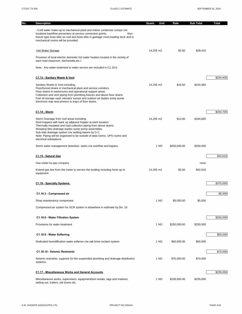
CTCDC T3-20A CLASS C ESTIMATE SEPTEMBER 02, 2010
No. Description Quant. Unit Rate Sub Total Total
- Cold water make-up to mechanical plant and indoor condenser sumps c/w localized backflow preventers at service connection points. Non-freeze type hose bibs on roof and hose bibs in garbage room,loading dock and in mechanical rooms will be provided.
Hot Water Storage 14,205 m2 $2.00 $28,410
Provision of local electric domestic hot water heaters located in the vicinity of each load (wasroom, kitchenette,etc.)
Note : Any water treatment to water service are included in C1.16.6
C1.13 - Sanitary Waste & Vent $234,400
Sanitary Waste & Vent including: 14,205 m2 $16.50 $234,383Floor/funnel drains in mechanical plant and service corridors.Floor drains in washrooms and operational support areas.Collection and vent piping from plumbing fixtures and above floor drainsFuel oil storage vault ,elevator sumps and outdoor pit duplex sump pump Electronic trap seal primers to traps of floor drains.
C1.14 - Storm $434,700
Storm Drainage from roof areas including: 14,205 m2 $13.00 $184,665Roof hoppers with back up adjacent hopper at each locationThermally insulated and clad collection piping from above drains.Weeping tiles drainage duplex sump pump assembliesSub-slab drainage system c/w settling basins by G.C.Note: Piping will be organized to be outside of data rooms. UPS rooms and electrical substations.
Storm water management detention tanks c/w overflow and bypass 1 NO $250,000.00 $250,000
C1.15 - Natural Gas $42,615
Gas meter by gas company none
Extend gas line from the meter to service the buiding including hook-up to equipment
14,205 m2 $3.00 $42,615
C1.16 - Specialty Systems: $375,000
C1.16.3 - Compressed air $5,000
Shop maintenance compressor 1 NO $5,000.00 $5,000
Compressed air system for SCR system is elsewhere in estimate by Div. 16
C1.16.6 - Water Filtration System $250,000
Provisions for water treatment 1 NO $250,000.00 $250,000
C1.16.9 - Water Softening $50,000
Dedicated humidification water softener c/w salt brine reclaim system 1 NO $50,000.00 $50,000
C1.16.10 - Seismic Restraints $70,000
Seismic restraints, supports for the suspended plumbing and drainage distribution systems.
1 NO $70,000.00 $70,000
C1.17 - Miscellaneous Works and General Accounts $235,000
Miscellaneous works, supervision, equipment/tool rentals, tags and markers, setting out, trailers, job boxes etc.
1 NO $235,000.00 $235,000
A.W. HOOKER ASSOCIATES LTD. PROJECT NO:109144 PAGE A19
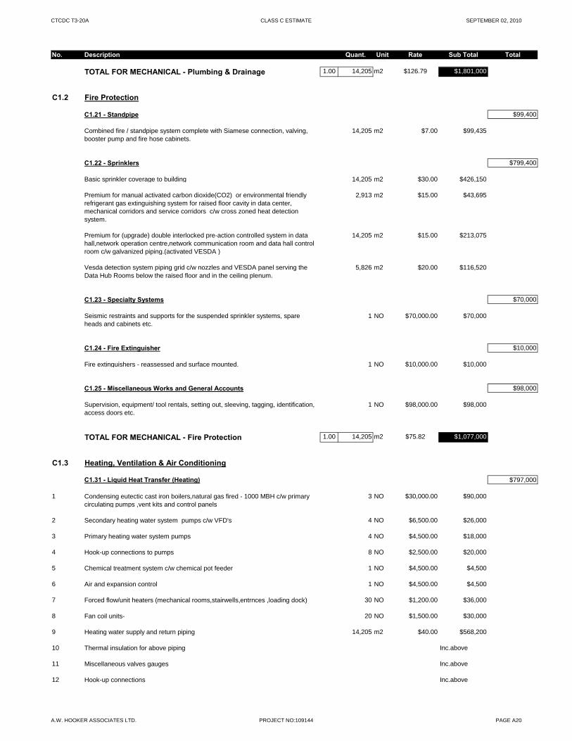
CTCDC T3-20A CLASS C ESTIMATE SEPTEMBER 02, 2010
No. Description Quant. Unit Rate Sub Total Total
TOTAL FOR MECHANICAL - Plumbing & Drainage 1.00 14,205 m2 $126.79 $1,801,000
C1.2 Fire Protection
C1.21 - Standpipe $99,400
Combined fire / standpipe system complete with Siamese connection, valving, booster pump and fire hose cabinets.
14,205 m2 $7.00 $99,435
C1.22 - Sprinklers $799,400
Basic sprinkler coverage to building 14,205 m2 $30.00 $426,150
Premium for manual activated carbon dioxide(CO2) or environmental friendly refrigerant gas extinguishing system for raised floor cavity in data center, mechanical corridors and service corridors c/w cross zoned heat detection system.
2,913 m2 $15.00 $43,695
Premium for (upgrade) double interlocked pre-action controlled system in data hall,network operation centre,network communication room and data hall control room c/w galvanized piping.(activated VESDA )
14,205 m2 $15.00 $213,075
Vesda detection system piping grid c/w nozzles and VESDA panel serving the Data Hub Rooms below the raised floor and in the ceiling plenum.
5,826 m2 $20.00 $116,520
C1.23 - Specialty Systems $70,000
Seismic restraints and supports for the suspended sprinkler systems, spare heads and cabinets etc.
1 NO $70,000.00 $70,000
C1.24 - Fire Extinguisher $10,000
Fire extinguishers - reassessed and surface mounted. 1 NO $10,000.00 $10,000
C1.25 - Miscellaneous Works and General Accounts $98,000
Supervision, equipment/ tool rentals, setting out, sleeving, tagging, identification, access doors etc.
1 NO $98,000.00 $98,000
TOTAL FOR MECHANICAL - Fire Protection 1.00 14,205 m2 $75.82 $1,077,000
C1.3 Heating, Ventilation & Air Conditioning
C1.31 - Liquid Heat Transfer (Heating) $797,000
1 Condensing eutectic cast iron boilers,natural gas fired - 1000 MBH c/w primary circulating pumps ,vent kits and control panels
3 NO $30,000.00 $90,000
2 Secondary heating water system pumps c/w VFD's 4 NO $6,500.00 $26,000
3 Primary heating water system pumps 4 NO $4,500.00 $18,000
4 Hook-up connections to pumps 8 NO $2,500.00 $20,000
5 Chemical treatment system c/w chemical pot feeder 1 NO $4,500.00 $4,500
6 Air and expansion control 1 NO $4,500.00 $4,500
7 Forced flow/unit heaters (mechanical rooms,stairwells,entrnces ,loading dock) 30 NO $1,200.00 $36,000
8 Fan coil units- 20 NO $1,500.00 $30,000
9 Heating water supply and return piping 14,205 m2 $40.00 $568,200
10 Thermal insulation for above piping Inc.above
11 Miscellaneous valves gauges Inc.above
12 Hook-up connections Inc.above
A.W. HOOKER ASSOCIATES LTD. PROJECT NO:109144 PAGE A20
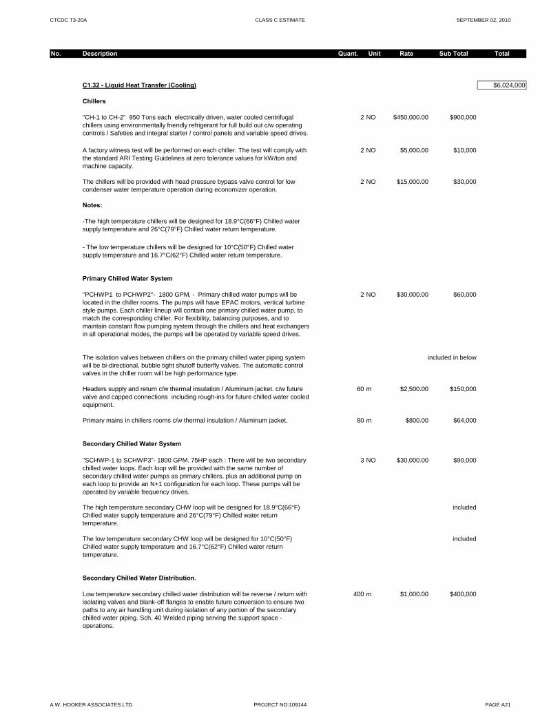
CTCDC T3-20A CLASS C ESTIMATE SEPTEMBER 02, 2010
No. Description Quant. Unit Rate Sub Total Total
C1.32 - Liquid Heat Transfer (Cooling) $6,024,000
Chillers
"CH-1 to CH-2" 950 Tons each electrically driven, water cooled centrifugal chillers using environmentally friendly refrigerant for full build out c/w operating controls / Safeties and integral starter / control panels and variable speed drives.
2 NO $450,000.00 $900,000
A factory witness test will be performed on each chiller. The test will comply with the standard ARI Testing Guidelines at zero tolerance values for kW/ton and machine capacity.
2 NO $5,000.00 $10,000
The chillers will be provided with head pressure bypass valve control for low condenser water temperature operation during economizer operation.
2 NO $15,000.00 $30,000
Notes:
-The high temperature chillers will be designed for 18.9°C(66°F) Chilled water supply temperature and 26°C(79°F) Chilled water return temperature.
- The low temperature chillers will be designed for 10°C(50°F) Chilled water supply temperature and 16.7°C(62°F) Chilled water return temperature.
Primary Chilled Water System
"PCHWP1 to PCHWP2"- 1800 GPM, - Primary chilled water pumps will be located in the chiller rooms. The pumps will have EPAC motors, vertical turbine style pumps. Each chiller lineup will contain one primary chilled water pump, to match the corresponding chiller. For flexibility, balancing purposes, and to maintain constant flow pumping system through the chillers and heat exchangers in all operational modes, the pumps will be operated by variable speed drives.
2 NO $30,000.00 $60,000
The isolation valves between chillers on the primary chilled water piping system will be bi-directional, bubble tight shutoff butterfly valves. The automatic control valves in the chiller room will be high performance type.
included in below
Headers supply and return c/w thermal insulation / Aluminum jacket c/w future 60 m $2 500 00 $150 000Headers supply and return c/w thermal insulation / Aluminum jacket. c/w future valve and capped connections including rough-ins for future chilled water cooled equipment.
60 m $2,500.00 $150,000
Primary mains in chillers rooms c/w thermal insulation / Aluminum jacket. 80 m $800.00 $64,000
Secondary Chilled Water System
"SCHWP-1 to SCHWP3"- 1800 GPM. 75HP each : There will be two secondary chilled water loops. Each loop will be provided with the same number of secondary chilled water pumps as primary chillers, plus an additional pump on each loop to provide an N+1 configuration for each loop. These pumps will be operated by variable frequency drives.
3 NO $30,000.00 $90,000
The high temperature secondary CHW loop will be designed for 18.9°C(66°F) Chilled water supply temperature and 26°C(79°F) Chilled water return temperature.
included
The low temperature secondary CHW loop will be designed for 10°C(50°F) Chilled water supply temperature and 16.7°C(62°F) Chilled water return temperature.
included
Secondary Chilled Water Distribution.
Low temperature secondary chilled water distribution will be reverse / return with isolating valves and blank-off flanges to enable future conversion to ensure two paths to any air handling unit during isolation of any portion of the secondary chilled water piping. Sch. 40 Welded piping serving the support space - operations.
400 m $1,000.00 $400,000
A.W. HOOKER ASSOCIATES LTD. PROJECT NO:109144 PAGE A21
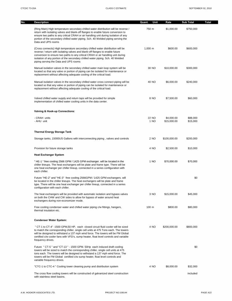
CTCDC T3-20A CLASS C ESTIMATE SEPTEMBER 02, 2010
No. Description Quant. Unit Rate Sub Total Total
(Ring Main) High temperature secondary chilled water distribution will be reverse / return with isolating valves and blank-off flanges to enable future conversion to ensure two paths to any critical CRAH or air handling unit during isolation of any portion of the secondary chilled water piping. Sch. 40 Welded piping serving the Data and UPS rooms
750 m $1,000.00 $750,000
(Cross connects) High temperature secondary chilled water distribution will be reverse / return with isolating valves and blank-off flanges to enable future conversion to ensure two paths to any critical CRAH or air handling unit during isolation of any portion of the secondary chilled water piping. Sch. 40 Welded piping serving the Data and UPS rooms
1,000 m $600.00 $600,000
Manual isolation valves in the secondary chilled water main loop system will be located so that any valve or portion of piping can be isolated for maintenance or replacement without affecting adequate cooling of the critical load.
30 NO $10,000.00 $300,000
Manual isolation valves in the secondary chilled water cross connect piping will be located so that any valve or portion of piping can be isolated for maintenance or replacement without affecting adequate cooling of the critical load.
40 NO $6,000.00 $240,000
Valved chilled water supply and return taps will be provided for simple implementation of chilled water cooling units in the data center.
8 NO $7,500.00 $60,000
Valving & Hook-up Connections:
- CRAH units 22 NO $4,000.00 $88,000- AHU unit 1 NO $15,000.00 $15,000
Thermal Energy Storage Tank
Storage tanks, 15000US Gallons with interconnecting piping , valves and controls 2 NO $100,000.00 $200,000
Provision for future storage tanks 4 NO $2,500.00 $10,000
Heat Exchanger System
" HE 1 " free cooling 2566 GPM / 1425 GPM exchanger will be located in the 1 NO $70 000 00 $70 000" HE-1 " free cooling 2566 GPM / 1425 GPM exchanger. will be located in the chiller lineups. The heat exchangers will be plate and frame type. There will be one heat exchanger per chiller lineup, connected in a series configuration with each chiller.
1 NO $70,000.00 $70,000
Future "HE-2" and "HE-3" free cooling 2566GPM / 1425 GPM exchangers. will be located in the chiller lineups. The heat exchangers will be plate and frame type. There will be one heat exchanger per chiller lineup, connected in a series configuration with each chiller.
$0
The heat exchangers will be provided with automatic isolation and bypass valves on both the CHW and CW sides to allow for bypass of water around heat exchangers during non-economizer mode.
3 NO $15,000.00 $45,000
Free cooling condenser water and chilled water piping c/w fittings, hangers, thermal insulation etc.
100 m $800.00 $80,000
Condenser Water System:
" CT-1 to CT-4" -1500 GPM,50 HP, each closed circuit fluid cooler will be sized to match the corresponding chiller, single cell units at 475 Tons each. The towers will be designed to withstand a 137 mph wind force. The towers will be FM Global certified c/w cooler fans with VFD's, sump heater, float level controls and variable frequency drives.
4 NO $200,000.00 $800,000
Future " CT-5 " and "CT-13 " - 1500 GPM. 50Hp each induced draft cooling towers will be sized to match the corresponding chiller, single cell units at 475 tons each. The towers will be designed to withstand a 137 mph wind force. The towers will be FM Global certified c/w sump heater, float level controls and variable frequency drives.
$0
"CTC-1 to CTC-4 " Cooling tower cleaning pump and distribution system 4 NO $8,000.00 $32,000
The cross flow cooling towers will be constructed of galvanized steel construction with stainless steel basins.
included
A.W. HOOKER ASSOCIATES LTD. PROJECT NO:109144 PAGE A22
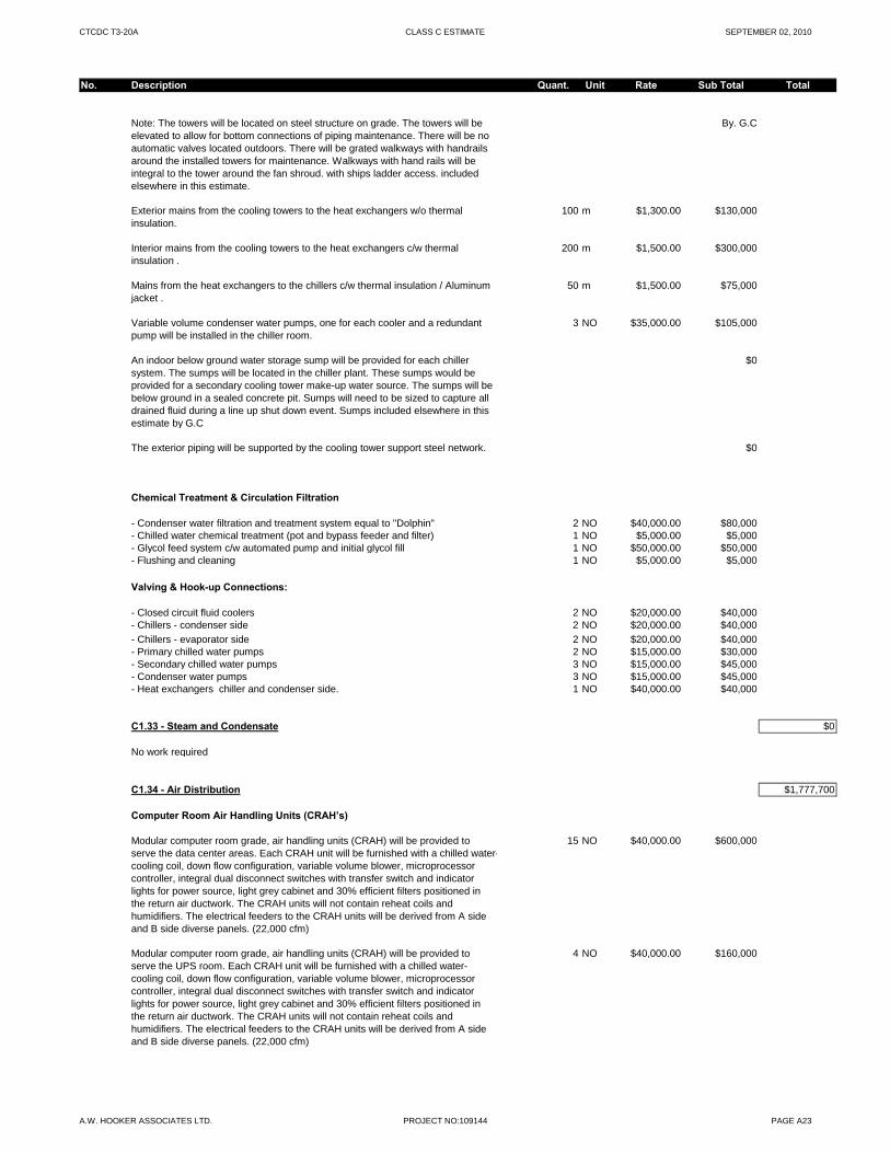
CTCDC T3-20A CLASS C ESTIMATE SEPTEMBER 02, 2010
No. Description Quant. Unit Rate Sub Total Total
Note: The towers will be located on steel structure on grade. The towers will be elevated to allow for bottom connections of piping maintenance. There will be no automatic valves located outdoors. There will be grated walkways with handrails around the installed towers for maintenance. Walkways with hand rails will be integral to the tower around the fan shroud. with ships ladder access. included elsewhere in this estimate.
By. G.C
Exterior mains from the cooling towers to the heat exchangers w/o thermal insulation.
100 m $1,300.00 $130,000
Interior mains from the cooling towers to the heat exchangers c/w thermal insulation .
200 m $1,500.00 $300,000
Mains from the heat exchangers to the chillers c/w thermal insulation / Aluminum jacket .
50 m $1,500.00 $75,000
Variable volume condenser water pumps, one for each cooler and a redundant pump will be installed in the chiller room.
3 NO $35,000.00 $105,000
An indoor below ground water storage sump will be provided for each chiller system. The sumps will be located in the chiller plant. These sumps would be provided for a secondary cooling tower make-up water source. The sumps will be below ground in a sealed concrete pit. Sumps will need to be sized to capture all drained fluid during a line up shut down event. Sumps included elsewhere in this estimate by G.C
$0
The exterior piping will be supported by the cooling tower support steel network. $0
Chemical Treatment & Circulation Filtration
- Condenser water filtration and treatment system equal to "Dolphin" 2 NO $40,000.00 $80,000- Chilled water chemical treatment (pot and bypass feeder and filter) 1 NO $5,000.00 $5,000- Glycol feed system c/w automated pump and initial glycol fill 1 NO $50,000.00 $50,000- Flushing and cleaning 1 NO $5,000.00 $5,000
Valving & Hook-up Connections:
- Closed circuit fluid coolers 2 NO $20,000.00 $40,000$ , $ ,- Chillers - condenser side 2 NO $20,000.00 $40,000
- Chillers - evaporator side 2 NO $20,000.00 $40,000- Primary chilled water pumps 2 NO $15,000.00 $30,000- Secondary chilled water pumps 3 NO $15,000.00 $45,000- Condenser water pumps 3 NO $15,000.00 $45,000- Heat exchangers chiller and condenser side. 1 NO $40,000.00 $40,000
C1.33 - Steam and Condensate $0
No work required
C1.34 - Air Distribution $1,777,700
Computer Room Air Handling Units (CRAH’s)
Modular computer room grade, air handling units (CRAH) will be provided to serve the data center areas. Each CRAH unit will be furnished with a chilled water-cooling coil, down flow configuration, variable volume blower, microprocessor controller, integral dual disconnect switches with transfer switch and indicator lights for power source, light grey cabinet and 30% efficient filters positioned in the return air ductwork. The CRAH units will not contain reheat coils and humidifiers. The electrical feeders to the CRAH units will be derived from A side and B side diverse panels. (22,000 cfm)
15 NO $40,000.00 $600,000
Modular computer room grade, air handling units (CRAH) will be provided to serve the UPS room. Each CRAH unit will be furnished with a chilled water-cooling coil, down flow configuration, variable volume blower, microprocessor controller, integral dual disconnect switches with transfer switch and indicator lights for power source, light grey cabinet and 30% efficient filters positioned in the return air ductwork. The CRAH units will not contain reheat coils and humidifiers. The electrical feeders to the CRAH units will be derived from A side and B side diverse panels. (22,000 cfm)
4 NO $40,000.00 $160,000
A.W. HOOKER ASSOCIATES LTD. PROJECT NO:109144 PAGE A23
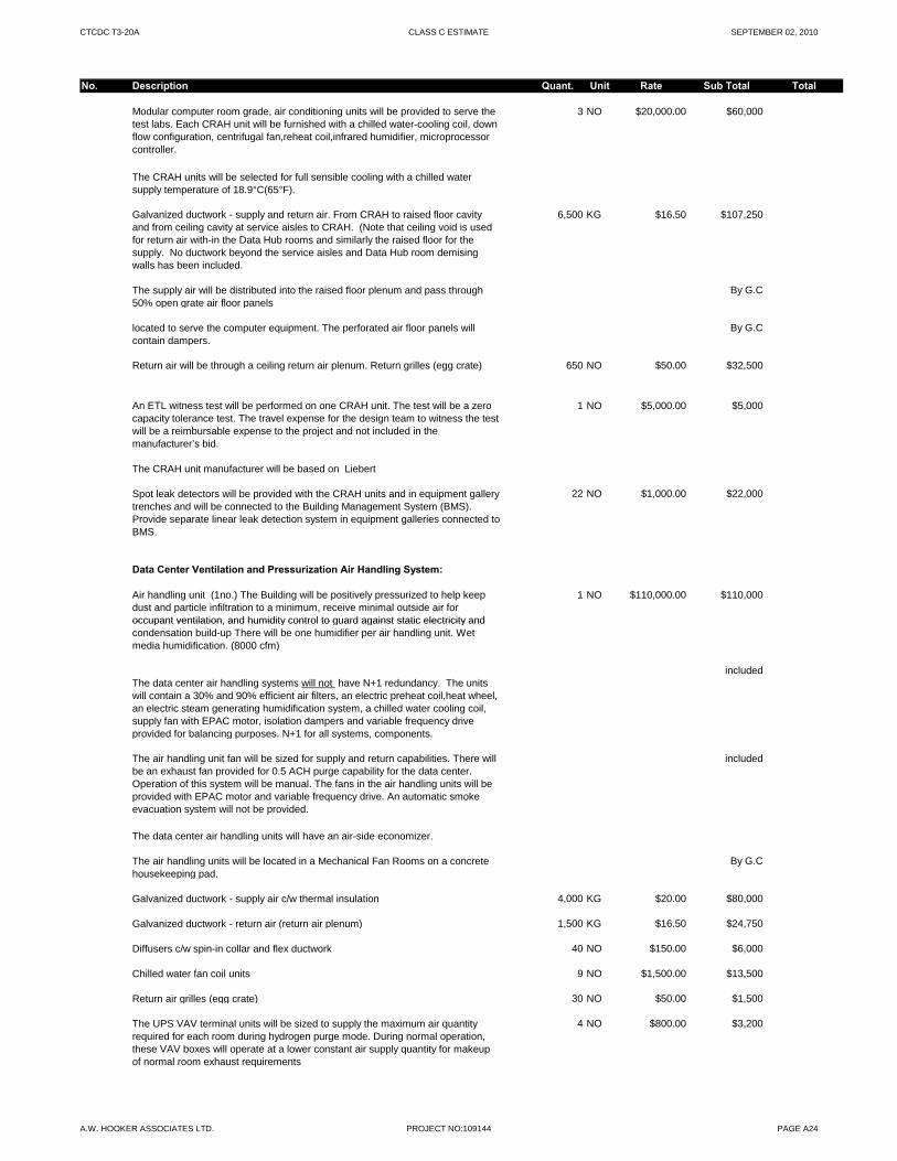
CTCDC T3-20A CLASS C ESTIMATE SEPTEMBER 02, 2010
No. Description Quant. Unit Rate Sub Total Total
Modular computer room grade, air conditioning units will be provided to serve the test labs. Each CRAH unit will be furnished with a chilled water-cooling coil, down flow configuration, centrifugal fan,reheat coil,infrared humidifier, microprocessor controller.
3 NO $20,000.00 $60,000
The CRAH units will be selected for full sensible cooling with a chilled water supply temperature of 18.9°C(65°F).
Galvanized ductwork - supply and return air. From CRAH to raised floor cavity and from ceiling cavity at service aisles to CRAH. (Note that ceiling void is used for return air with-in the Data Hub rooms and similarly the raised floor for the supply. No ductwork beyond the service aisles and Data Hub room demising walls has been included.
6,500 KG $16.50 $107,250
The supply air will be distributed into the raised floor plenum and pass through 50% open grate air floor panels
By G.C
located to serve the computer equipment. The perforated air floor panels will contain dampers.
By G.C
Return air will be through a ceiling return air plenum. Return grilles (egg crate) 650 NO $50.00 $32,500
An ETL witness test will be performed on one CRAH unit. The test will be a zero capacity tolerance test. The travel expense for the design team to witness the test will be a reimbursable expense to the project and not included in the manufacturer’s bid.
1 NO $5,000.00 $5,000
The CRAH unit manufacturer will be based on Liebert
Spot leak detectors will be provided with the CRAH units and in equipment gallery trenches and will be connected to the Building Management System (BMS). Provide separate linear leak detection system in equipment galleries connected to BMS.
22 NO $1,000.00 $22,000
Data Center Ventilation and Pressurization Air Handling System:
Air handling unit (1no.) The Building will be positively pressurized to help keep dust and particle infiltration to a minimum, receive minimal outside air for occupant ventilation and humidity control to guard against static electricity and
1 NO $110,000.00 $110,000
occupant ventilation, and humidity control to guard against static electricity and condensation build-up There will be one humidifier per air handling unit. Wet media humidification. (8000 cfm)
The data center air handling systems will not have N+1 redundancy. The units will contain a 30% and 90% efficient air filters, an electric preheat coil,heat wheel, an electric steam generating humidification system, a chilled water cooling coil, supply fan with EPAC motor, isolation dampers and variable frequency drive provided for balancing purposes. N+1 for all systems, components.
included
The air handling unit fan will be sized for supply and return capabilities. There will be an exhaust fan provided for 0.5 ACH purge capability for the data center. Operation of this system will be manual. The fans in the air handling units will be provided with EPAC motor and variable frequency drive. An automatic smoke evacuation system will not be provided.
included
The data center air handling units will have an air-side economizer.
The air handling units will be located in a Mechanical Fan Rooms on a concrete housekeeping pad.
By G.C
Galvanized ductwork - supply air c/w thermal insulation 4,000 KG $20.00 $80,000
Galvanized ductwork - return air (return air plenum) 1,500 KG $16.50 $24,750
Diffusers c/w spin-in collar and flex ductwork 40 NO $150.00 $6,000
Chilled water fan coil units 9 NO $1,500.00 $13,500
Return air grilles (egg crate) 30 NO $50.00 $1,500
The UPS VAV terminal units will be sized to supply the maximum air quantity required for each room during hydrogen purge mode. During normal operation, these VAV boxes will operate at a lower constant air supply quantity for makeup of normal room exhaust requirements
4 NO $800.00 $3,200
A.W. HOOKER ASSOCIATES LTD. PROJECT NO:109144 PAGE A24
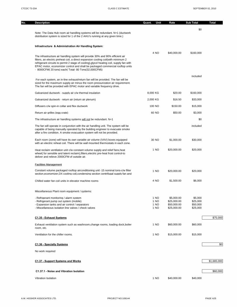
CTCDC T3-20A CLASS C ESTIMATE SEPTEMBER 02, 2010
No. Description Quant. Unit Rate Sub Total Total
Note: The Data Hub room air handling systems will be redundant. N+1 (ductwork distribution system is sized for 1 of the 2 AHU's running at any given time.)
$0
Infrastructure & Administration Air Handling System:
The infrastructure air handling system will provide 30% and 90% efficient air filters, an electric preheat coil, a direct expansion cooling coil(with minimum 2 refrigerant circuits to permit 2 stage of cooling),glycol heating coil, supply fan with EPAC motor, economizer control and shall be packaged commercial rooftop units - 8000CFM( 20 tons) each( Total- 80 Tons(32,000CFM))
4 NO $40,000.00 $160,000
For each system, an in-line exhaust/return fan will be provided. The fan will be sized for the maximum supply air minus the room pressurization air requirement. The fan will be provided with EPAC motor and variable frequency drive.
included
Galvanized ductwork - supply air c/w thermal insulation 8,000 KG $20.00 $160,000
Galvanized ductwork - return air (return air plenum) 2,000 KG $16.50 $33,000
Diffusers c/w spin-in collar and flex ductwork 100 NO $150.00 $15,000
Return air grilles (egg crate) 60 NO $50.00 $3,000
The infrastructure air handling systems will not be redundant. N+1 $0
The fan will operate in conjunction with the air handling unit. The system will be capable of being manually operated by the building engineer to evacuate smoke after a fire condition. A smoke evacuation system will not be provided.
included
Each room (zone) will have its own variable air volume (VAV) boxes equipped with an electric reheat coil. There will be wall mounted thermostats in each zone.
30 NO $1,000.00 $30,000
Heat reclaim ventilation unit c/w constant volume supply and relief fans,heat wheel( for sensible and latent reclaim),filters,electric pre-heat frost control-to deliver and relieve 2000CFM of outside air.
1 NO $20,000.00 $20,000
Facilities ManagementFacilities Management
Constant volume packaged rooftop airconditioning unit -15 nominal tons-c/w filter section,economizer,DX cooling coil,condensing section centrifugal supply fan and
1 NO $20,000.00 $20,000
Chilled water fan coil units in elevator machine rooms 4 NO $1,500.00 $6,000
Miscellaneous Plant room equipment / systems:
- Refrigerant monitoring / alarm system 1 NO $5,000.00 $5,000- Refrigerant pump out system (mobile) 1 NO $25,000.00 $25,000- Expansion tanks and air control / separators 1 NO $50,000.00 $50,000- Miscellaneous isolation line valves / check valves 1 NO $25,000.00 $25,000
C1.35 - Exhaust Systems $75,000
Exhaust ventilation system such as washroom,change rooms, loading dock,boiler room, etc.
1 NO $60,000.00 $60,000
Ventilation for the chiller rooms. 1 NO $15,000.00 $15,000
C1.36 - Specialty Systems $0
No work required
C1.37 - Support Systems and Works $1,665,000
C1.37.1 - Noise and Vibration Isolation $60,000
Vibration Isolation 1 NO $40,000.00 $40,000
A.W. HOOKER ASSOCIATES LTD. PROJECT NO:109144 PAGE A25
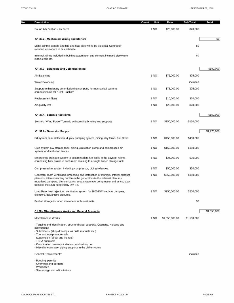
CTCDC T3-20A CLASS C ESTIMATE SEPTEMBER 02, 2010
No. Description Quant. Unit Rate Sub Total Total
Sound Attenuation - silencers 1 NO $20,000.00 $20,000
C1.37.2 - Mechanical Wiring and Starters $0
Motor control centers and line and load side wiring by Electrical Contractor included elsewhere in this estimate.
$0
Interlock wiring included in building automation sub contract included elsewhere in this estimate.
$0
C1.37.3 - Balancing and Commissioning $180,000
Air Balancing 1 NO $75,000.00 $75,000
Water Balancing included
Support to third party commissioning company for mechanical systems commissioning for "Best Practice"
1 NO $75,000.00 $75,000
Replacement filters 1 NO $10,000.00 $10,000
Air quality test 1 NO $20,000.00 $20,000
C1.37.4 - Seismic Restraints $150,000
Seismic / Wind Force/ Tornado withstanding bracing and supports 1 NO $150,000.00 $150,000
C1.37.6 - Generator Support $1,275,000
Fill system, leak detection, duplex pumping system, piping, day tanks, fuel filters 1 NO $450,000.00 $450,000
Urea system c/w storage tank, piping, circulation pump and compressed air system for distribution lances.
1 NO $150,000.00 $150,000
Emergency drainage system to accommodate fuel spills in the daytank rooms comprising floor drains in each room draining to a single buried storage tank
1 NO $25,000.00 $25,000p g g g g
Compressed air system including compressor, piping to lances. 1 NO $50,000.00 $50,000
Generator room ventilation, breeching and installation of mufflers, Intake/ exhaust plenums, interconnecting duct from the generators to the exhaust plenums, motorized dampers, silencer banks, urea system c/w compressor and lance, labor to install the SCR supplied by Div. 16.
1 NO $350,000.00 $350,000
Load Bank heat rejection / ventilation system for 2600 KW load c/w dampers, silencers, galvanized plenums.
1 NO $250,000.00 $250,000
Fuel oil storage included elsewhere in this estimate. $0
C1.38 - Miscellaneous Works and General Accounts $1,550,000
Miscellaneous Works: 1 NO $1,550,000.00 $1,550,000
- Tagging and identification, structural steel supports, Crainage, Hoisting and millwrighting- Submittals - (shop drawings, as built, manuals etc.)- Tool and equipment rentals- Supervision (direct and indirect)- TSSA approvals- Coordination drawings / sleeving and setting out.- Miscellaneous steel piping supports in the chiller rooms
General Requirements: included
- Bonding, permits- Overhead and burdens- Warranties- Site storage and office trailers
A.W. HOOKER ASSOCIATES LTD. PROJECT NO:109144 PAGE A26
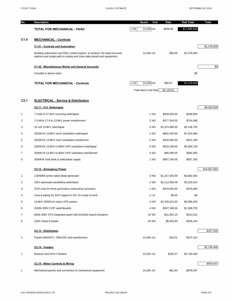
CTCDC T3-20A CLASS C ESTIMATE SEPTEMBER 02, 2010
No. Description Quant. Unit Rate Sub Total Total
TOTAL FOR MECHANICAL - HVAC 1.00 14,205 m2 $836.96 $11,889,000
C1.4 MECHANICAL - Controls
C1.41 - Controls and Automation $1,278,000
Building automation and DDC control system to achieve 1N head end work stations and single path to unitary and zone data panels and equipment.
14,205 m2 $90.00 $1,278,000
C1.42 - Miscellaneous Works and General Accounts $0
Included in above rates $0
TOTAL FOR MECHANICAL - Controls 1.00 14,205 m2 $89.97 $1,278,000
Total Mech Unit Rate $1,129.51
C2.1 ELECTRICAL - Service & Distribution
C2.11 - H.V. Switchgear $8,250,828
1 7 Cells of 27.6KV incoming switchgear 1 NO $439,500.00 $439,500
2 7.5 MVA 27.6 to 13.8KV power transformers 2 NO $377,244.00 $754,488
3 10 cell 13.8KV switchgear 2 NO $1,074,360.00 $2,148,720
4 3333KVA 13.8KV mech substation switchgear 2 NO $662,340.00 $1,324,680
5 3333KVA 13.8KV mech substation transformer 2 NO $100,590.00 $201,180
6 2500KVA 13.8KV to 600V UPS substation switchgear 4 NO $516,180.00 $2,064,720
7 2500KVA 13.8KV to 600V UPS substation transformer 4 NO $90,090.00 $360,360
8 3000KW load bank & switchgear supply 1 NO $957,180.00 $957,180
C2.12 - Emergency Power $19,507,682
1 2.825MW prime rated diesel generator 3 NO $1,227,450.00 $3,682,350
2 15KV generator paralleling switchgear 2 NO $2,112,956.48 $4,225,913
3 SCR units for three generators subcontract provision 1 NO $315,000.00 $315,000
4 Urea & piping for SCR support in Div 15 scope of work 1 LS $0.00 $0
5 13.8KV 2500KVA rotary UPS system 4 NO $2,326,613.30 $9,306,453
6 2000A 400V COP switchboards 4 NO $327,180.00 $1,308,720
7 600A 400V STS integrated panel with 6X225A branch breakers 10 NO $41,301.23 $413,012
8 225A Panel & feeder 40 NO $6,405.84 $256,234
C2.13 - Distribution $227,422
1 Panels 600/347V, 208/120V and transformers 14,205 m2 $16.01 $227,422
C2.14 - Feeders $2,745,400
1 Busduct and HV/LV feeders 14,205 m2 $193.27 $2,745,400
C2.15 - Motor Controls & Wiring $878,437
1 Mechanical panels and connection to mechanical equipment 14,205 m2 $61.84 $878,437
A.W. HOOKER ASSOCIATES LTD. PROJECT NO:109144 PAGE A27
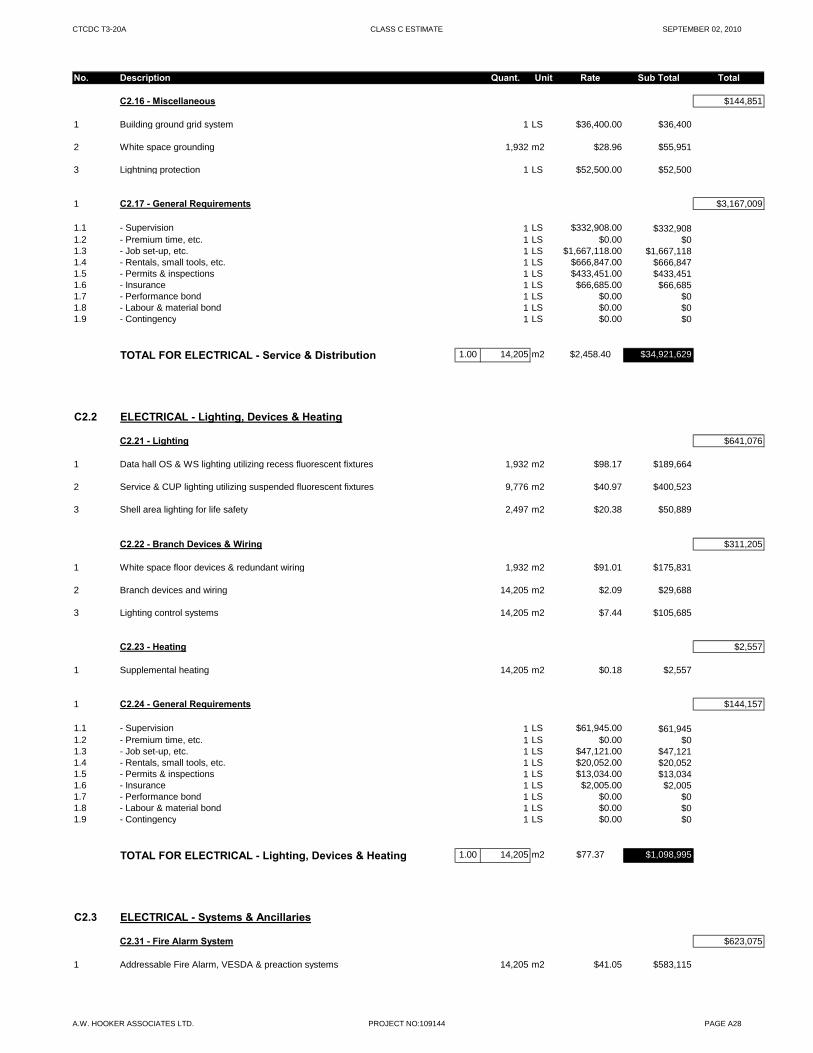
CTCDC T3-20A CLASS C ESTIMATE SEPTEMBER 02, 2010
No. Description Quant. Unit Rate Sub Total Total
C2.16 - Miscellaneous $144,851
1 Building ground grid system 1 LS $36,400.00 $36,400
2 White space grounding 1,932 m2 $28.96 $55,951
3 Lightning protection 1 LS $52,500.00 $52,500
1 C2.17 - General Requirements $3,167,009
1.1 - Supervision 1 LS $332,908.00 $332,9081.2 - Premium time, etc. 1 LS $0.00 $01.3 - Job set-up, etc. 1 LS $1,667,118.00 $1,667,1181.4 - Rentals, small tools, etc. 1 LS $666,847.00 $666,8471.5 - Permits & inspections 1 LS $433,451.00 $433,4511.6 - Insurance 1 LS $66,685.00 $66,6851.7 - Performance bond 1 LS $0.00 $01.8 - Labour & material bond 1 LS $0.00 $01.9 - Contingency 1 LS $0.00 $0
TOTAL FOR ELECTRICAL - Service & Distribution 1.00 14,205 m2 $2,458.40 $34,921,629
C2.2 ELECTRICAL - Lighting, Devices & Heating
C2.21 - Lighting $641,076
1 Data hall OS & WS lighting utilizing recess fluorescent fixtures 1,932 m2 $98.17 $189,664
2 Service & CUP lighting utilizing suspended fluorescent fixtures 9,776 m2 $40.97 $400,523
3 Shell area lighting for life safety 2,497 m2 $20.38 $50,889
C2.22 - Branch Devices & Wiring $311,205
1 Whit fl d i & d d t i i 1 932 2 $91 01 $175 8311 White space floor devices & redundant wiring 1,932 m2 $91.01 $175,831
2 Branch devices and wiring 14,205 m2 $2.09 $29,688
3 Lighting control systems 14,205 m2 $7.44 $105,685
C2.23 - Heating $2,557
1 Supplemental heating 14,205 m2 $0.18 $2,557
1 C2.24 - General Requirements $144,157
1.1 - Supervision 1 LS $61,945.00 $61,9451.2 - Premium time, etc. 1 LS $0.00 $01.3 - Job set-up, etc. 1 LS $47,121.00 $47,1211.4 - Rentals, small tools, etc. 1 LS $20,052.00 $20,0521.5 - Permits & inspections 1 LS $13,034.00 $13,0341.6 - Insurance 1 LS $2,005.00 $2,0051.7 - Performance bond 1 LS $0.00 $01.8 - Labour & material bond 1 LS $0.00 $01.9 - Contingency 1 LS $0.00 $0
TOTAL FOR ELECTRICAL - Lighting, Devices & Heating 1.00 14,205 m2 $77.37 $1,098,995
C2.3 ELECTRICAL - Systems & Ancillaries
C2.31 - Fire Alarm System $623,075
1 Addressable Fire Alarm, VESDA & preaction systems 14,205 m2 $41.05 $583,115
A.W. HOOKER ASSOCIATES LTD. PROJECT NO:109144 PAGE A28
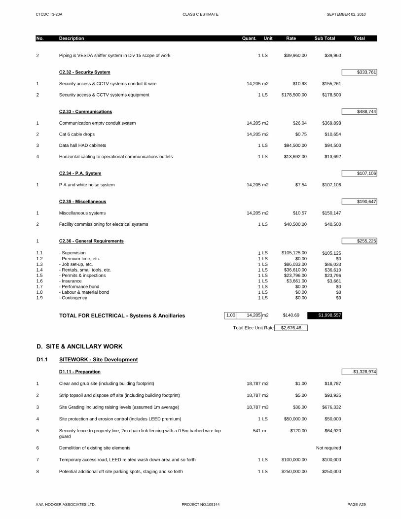
CTCDC T3-20A CLASS C ESTIMATE SEPTEMBER 02, 2010
No. Description Quant. Unit Rate Sub Total Total
2 Piping & VESDA sniffer system in Div 15 scope of work 1 LS $39,960.00 $39,960
C2.32 - Security System $333,761
1 Security access & CCTV systems conduit & wire 14,205 m2 $10.93 $155,261
2 Security access & CCTV systems equipment 1 LS $178,500.00 $178,500
C2.33 - Communications $488,744
1 Communication empty conduit system 14,205 m2 $26.04 $369,898
2 Cat 6 cable drops 14,205 m2 $0.75 $10,654
3 Data hall HAD cabinets 1 LS $94,500.00 $94,500
4 Horizontal cabling to operational communications outlets 1 LS $13,692.00 $13,692
C2.34 - P.A. System $107,106
1 P A and white noise system 14,205 m2 $7.54 $107,106
C2.35 - Miscellaneous $190,647
1 Miscellaneous systems 14,205 m2 $10.57 $150,147
2 Facility commissioning for electrical systems 1 LS $40,500.00 $40,500
1 C2.36 - General Requirements $255,225
1.1 - Supervision 1 LS $105,125.00 $105,1251.2 - Premium time, etc. 1 LS $0.00 $01.3 - Job set-up, etc. 1 LS $86,033.00 $86,0331.4 - Rentals, small tools, etc. 1 LS $36,610.00 $36,6101.5 - Permits & inspections 1 LS $23,796.00 $23,796p , ,1.6 - Insurance 1 LS $3,661.00 $3,6611.7 - Performance bond 1 LS $0.00 $01.8 - Labour & material bond 1 LS $0.00 $01.9 - Contingency 1 LS $0.00 $0
TOTAL FOR ELECTRICAL - Systems & Ancillaries 1.00 14,205 m2 $140.69 $1,998,557
Total Elec Unit Rate $2,676.46
D. SITE & ANCILLARY WORK
D1.1 SITEWORK - Site Development
D1.11 - Preparation $1,328,974
1 Clear and grub site (including building footprint) 18,787 m2 $1.00 $18,787
2 Strip topsoil and dispose off site (including building footprint) 18,787 m2 $5.00 $93,935
3 Site Grading including raising levels (assumed 1m average) 18,787 m3 $36.00 $676,332
4 Site protection and erosion control (includes LEED premium) 1 LS $50,000.00 $50,000
5 Security fence to property line, 2m chain link fencing with a 0.5m barbed wire top guard
541 m $120.00 $64,920
6 Demolition of existing site elements Not required
7 Temporary access road, LEED related wash down area and so forth 1 LS $100,000.00 $100,000
8 Potential additional off site parking spots, staging and so forth 1 LS $250,000.00 $250,000
A.W. HOOKER ASSOCIATES LTD. PROJECT NO:109144 PAGE A29

CTCDC T3-20A CLASS C ESTIMATE SEPTEMBER 02, 2010
No. Description Quant. Unit Rate Sub Total Total
9 Temporary fence / hoarding 1 LS $75,000.00 $75,000
D1.12 - Hard Surfaces $587,405
1 Asphalt paving including:
1.1 - heavy duty to fire route laneway and snow collection area, assumed 1,476 m2 $50.00 $73,8001.2 - medium duty to parking spaces and laneway, assumed 4,338 m2 $40.00 $173,5201.3 - extra over for loading dock bay 250 m2 $60.00 $15,000
2 Concrete curbs 1,049 m $55.00 $57,695
3 Extra over for depressed curb, assumed required 4 m $60.00 $240
4 Concrete paving to walkways at proposed and existing building perimeter 1,308 m2 $65.00 $85,020
5 Concrete paving to along the property line at both south and west elevations, assumed
536 m2 $65.00 $34,840
6 Concrete paving at security booth Island 66 m2 $65.00 $4,290
7 Outdoor patio/ sitting area for employees Not required
8 Concrete equipment pads 1 LS $5,000.00 $5,000
9 Line painting (100 spots) 1 LS $7,000.00 $7,000
10 Concrete pad to entrances and exits 2 NO $3,000.00 $6,000
11 Allowance for upgraded paving at entrance and site access including connections to streets
1 LS $50,000.00 $50,000
12 City works and repairs at tie in to existing sidewalk, driveway etc (excludes new intersection lights or major upgrades)
1 LS $75,000.00 $75,000
D1.13 - Improvements $1,038,000
1 Security booth and island at main entrance gate (3 5m x 5 5m booth) height 1 LS $50 000 00 $50 0001 Security booth and island at main entrance gate, (3.5m x 5.5m booth), height unknown
1 LS $50,000.00 $50,000
2 Retaining walls (placeholder allowance) 1 LS $500,000.00 $500,000
3 Large sliding gates3.1 - loading area/ emergency exit 1 NO $40,000.00 $40,0003.2 - main entrance (for entrance and exit- 6m wide) 2 NO $25,000.00 $50,000
4 Perimeter security fence Refer to site preparation
5 Fence to outdoor equipment, patio, garbage and so forth 1 LS $15,000.00 $15,000
6 Fence to outdoor storage compound for parking of city of Toronto owned vehicles 1 LS $30,000.00 $30,000
7 Bollards 1 LS $25,000.00 $25,000
8 Vehicular entrance, site way finding and parking signage 1 LS $10,000.00 $10,000
9 Card reader access By electrical
10 Allowance for site accessories including benches, garbage cans, bicycle stall etc. 1 LS $5,000.00 $5,000
11 Modify existing storm water retention pond (scope to be defined, assume this project will connect to it)
1 LS $50,000.00 $50,000
12 Address podium at entrance Excluded, not typically provided with CC
13 Barrier arms at entrance Not Required
14 Site furniture (assumed minimal) 1 LS $5,000.00 $5,000
15 Irrigation system Excluded
A.W. HOOKER ASSOCIATES LTD. PROJECT NO:109144 PAGE A30
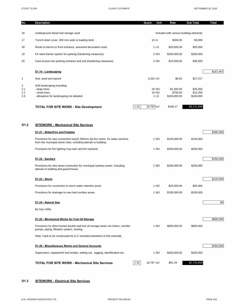
CTCDC T3-20A CLASS C ESTIMATE SEPTEMBER 02, 2010
No. Description Quant. Unit Rate Sub Total Total
16 Underground diesel fuel storage vault Included with various building elements
17 Trench drain cover, 300 mm wide to loading dock 10 m $300.00 $3,000
18 Rocks to berms to front entrance, assumed decorative rocks 1 LS $25,000.00 $25,000
19 K4 rated barrier system for parking (hardening measures) 2 NO $100,000.00 $200,000
20 Card access into parking entrance and exit (hardening measures) 2 NO $15,000.00 $30,000
D1.14 - Landscaping $167,467
1 Sod, seed and topsoil 3,202 m2 $8.50 $27,217
2 Soft landscaping including:2.1 - large trees 26 NO $1,000.00 $26,0002.2 - small trees 19 NO $750.00 $14,2502.3 - allowance for landscaping not detailed 1 LS $100,000.00 $100,000
TOTAL FOR SITE WORK - Site Development 1.32 18,787 m2 $166.17 $3,121,846
D1.2 SITEWORK - Mechanical Site Services
D1.21 - Water(Fire and Potable) $390,000
Provisions for new connection two(2) 200mm dia.fire mains for water services from the municipal street main, including laterals to building.
1 NO $140,000.00 $140,000
Provisions for fire fighting ring main and fire hydrants 1 NO $250,000.00 $250,000
D1.22 - Sanitary $150,000
P i i f t t ti f i i l it i l di 1 NO $150 000 00 $150 000Provisions for new street connection for municipal sanitary sewer, including laterals to building and guard-house.
1 NO $150,000.00 $150,000
D1.23 - Storm $125,000
Provisions for connection to storm water retention pond. 1 NO $25,000.00 $25,000
Provisions for drainage to new hard surface areas. 1 NO $100,000.00 $100,000
D1.24 - Natural Gas $0
By Gas Utility
D1.25 - Mechanical Works for Fuel Oil Storage $800,000
Provisions for direct buried double wall fuel oil storage tanks c/w indoor, transfer pumps, piping, filtration system, venting.
1 NO $800,000.00 $800,000
Note: Vault to be constructed by G.C included elsewhere in this estimate.
D1.26 - Miscellaneous Works and General Accounts $250,000
Supervision, equipment/ tool rentals, setting out, tagging, identification etc. 1 NO $250,000.00 $250,000
TOTAL FOR SITE WORK - Mechanical Site Services 1.32 18,787 m2 $91.29 $1,715,000
D1.3 SITEWORK - Electrical Site Services
A.W. HOOKER ASSOCIATES LTD. PROJECT NO:109144 PAGE A31
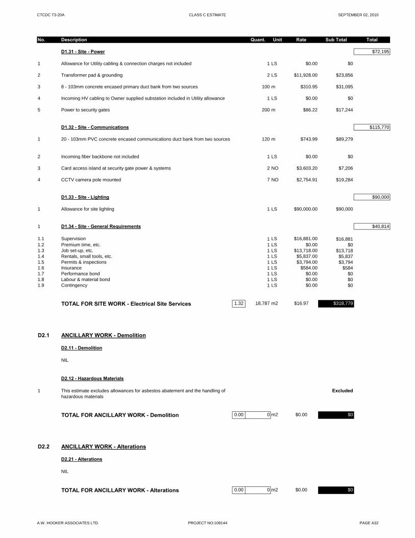
CTCDC T3-20A CLASS C ESTIMATE SEPTEMBER 02, 2010
No. Description Quant. Unit Rate Sub Total Total
D1.31 - Site - Power $72,195
1 Allowance for Utility cabling & connection charges not included 1 LS $0.00 $0
2 Transformer pad & grounding 2 LS $11,928.00 $23,856
3 8 - 103mm concrete encased primary duct bank from two sources 100 m $310.95 $31,095
4 Incoming HV cabling to Owner supplied substation included in Utility allowance 1 LS $0.00 $0
5 Power to security gates 200 m $86.22 $17,244
D1.32 - Site - Communications $115,770
1 20 - 103mm PVC concrete encased communications duct bank from two sources 120 m $743.99 $89,279
2 Incoming fiber backbone not included 1 LS $0.00 $0
3 Card access island at security gate power & systems 2 NO $3,603.20 $7,206
4 CCTV camera pole mounted 7 NO $2,754.91 $19,284
D1.33 - Site - Lighting $90,000
1 Allowance for site lighting 1 LS $90,000.00 $90,000
1 D1.34 - Site - General Requirements $40,814
1.1 Supervision 1 LS $16,881.00 $16,8811.2 Premium time, etc. 1 LS $0.00 $01.3 Job set-up, etc. 1 LS $13,718.00 $13,7181.4 Rentals, small tools, etc. 1 LS $5,837.00 $5,8371.5 Permits & inspections 1 LS $3,794.00 $3,7941.6 Insurance 1 LS $584.00 $5841.7 Performance bond 1 LS $0.00 $01.8 Labour & material bond 1 LS $0.00 $01.9 Contingency 1 LS $0.00 $0g y
TOTAL FOR SITE WORK - Electrical Site Services 1.32 18,787 m2 $16.97 $318,779
D2.1 ANCILLARY WORK - Demolition
D2.11 - Demolition
NIL
D2.12 - Hazardous Materials
1 This estimate excludes allowances for asbestos abatement and the handling of hazardous materials
Excluded
TOTAL FOR ANCILLARY WORK - Demolition 0.00 0 m2 $0.00 $0
D2.2 ANCILLARY WORK - Alterations
D2.21 - Alterations
NIL
TOTAL FOR ANCILLARY WORK - Alterations 0.00 0 m2 $0.00 $0
A.W. HOOKER ASSOCIATES LTD. PROJECT NO:109144 PAGE A32
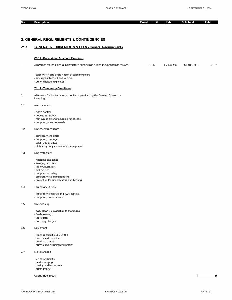
CTCDC T3-20A CLASS C ESTIMATE SEPTEMBER 02, 2010
No. Description Quant. Unit Rate Sub Total Total
Z. GENERAL REQUIREMENTS & CONTINGENCIES
Z1.1 GENERAL REQUIREMENTS & FEES - General Requirements
Z1.11 - Supervision & Labour Expenses
1 Allowance for the General Contractor's supervision & labour expenses as follows: 1 LS $7,404,990 $7,405,000 8.0%
- supervision and coordination of subcontractors- site superintendent and vehicle- general labour expenses
Z1.12 - Temporary Conditions
1 Allowance for the temporary conditions provided by the General Contractor including:
1.1 Access to site
- traffic control- pedestrian safety- removal of exterior cladding for access- temporary closure panels
1.2 Site accommodations:
- temporary site office- temporary signage- telephone and fax- stationary supplies and office equipment
1.3 Site protection:
- hoarding and gates hoarding and gates- safety guard rails- fire extinguishers- first aid kits- temporary shoring- temporary stairs and ladders- protection for site elevators and flooring
1.4 Temporary utilities:
- temporary construction power panels- temporary water source
1.5 Site clean up:
- daily clean up in addition to the trades- final cleaning- dump bins- dumping charges
1.6 Equipment:
- material hoisting equipment - cranes and operators- small tool rental- pumps and pumping equipment
1.7 Miscellaneous
- CPM scheduling- land surveying- testing and inspections- photography
Cash Allowances $0
A.W. HOOKER ASSOCIATES LTD. PROJECT NO:109144 PAGE A33
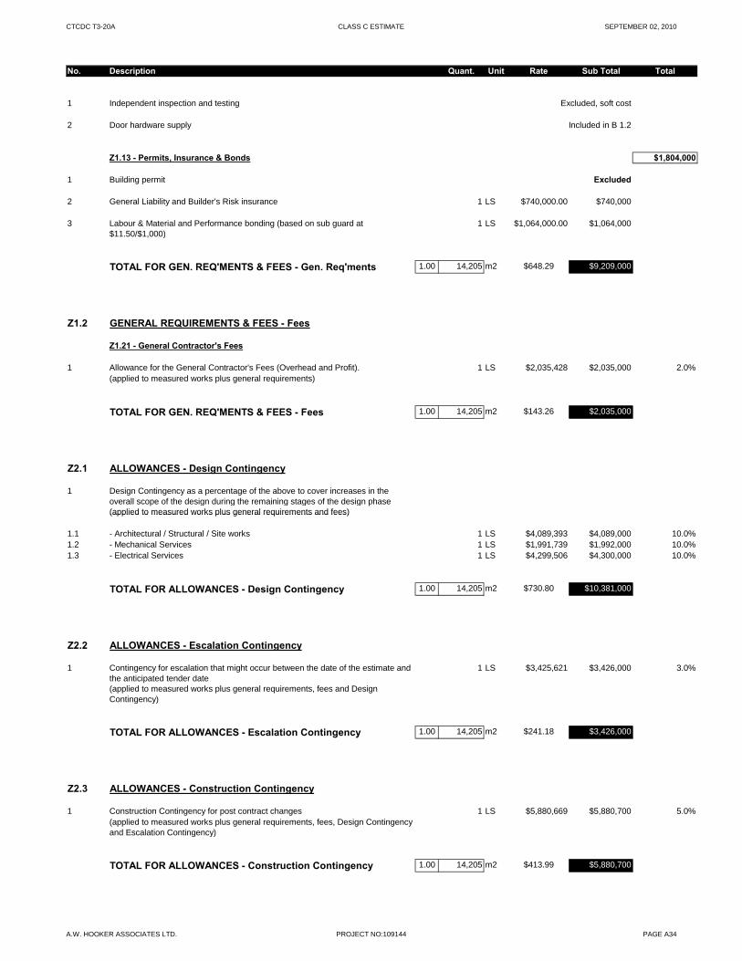
CTCDC T3-20A CLASS C ESTIMATE SEPTEMBER 02, 2010
No. Description Quant. Unit Rate Sub Total Total
1 Independent inspection and testing Excluded, soft cost
2 Door hardware supply Included in B 1.2
Z1.13 - Permits, Insurance & Bonds $1,804,000
1 Building permit Excluded
2 General Liability and Builder's Risk insurance 1 LS $740,000.00 $740,000
3 Labour & Material and Performance bonding (based on sub guard at $11.50/$1,000)
1 LS $1,064,000.00 $1,064,000
TOTAL FOR GEN. REQ'MENTS & FEES - Gen. Req'ments 1.00 14,205 m2 $648.29 $9,209,000
Z1.2 GENERAL REQUIREMENTS & FEES - Fees
Z1.21 - General Contractor's Fees
1 Allowance for the General Contractor's Fees (Overhead and Profit). 1 LS $2,035,428 $2,035,000 2.0%(applied to measured works plus general requirements)
TOTAL FOR GEN. REQ'MENTS & FEES - Fees 1.00 14,205 m2 $143.26 $2,035,000
Z2.1 ALLOWANCES - Design Contingency
1 Design Contingency as a percentage of the above to cover increases in the overall scope of the design during the remaining stages of the design phase(applied to measured works plus general requirements and fees)(applied to measured works plus general requirements and fees)
1.1 - Architectural / Structural / Site works 1 LS $4,089,393 $4,089,000 10.0%1.2 - Mechanical Services 1 LS $1,991,739 $1,992,000 10.0%1.3 - Electrical Services 1 LS $4,299,506 $4,300,000 10.0%
TOTAL FOR ALLOWANCES - Design Contingency 1.00 14,205 m2 $730.80 $10,381,000
Z2.2 ALLOWANCES - Escalation Contingency
1 Contingency for escalation that might occur between the date of the estimate and the anticipated tender date
1 LS $3,425,621 $3,426,000 3.0%
(applied to measured works plus general requirements, fees and Design Contingency)
TOTAL FOR ALLOWANCES - Escalation Contingency 1.00 14,205 m2 $241.18 $3,426,000
Z2.3 ALLOWANCES - Construction Contingency
1 Construction Contingency for post contract changes 1 LS $5,880,669 $5,880,700 5.0%(applied to measured works plus general requirements, fees, Design Contingency and Escalation Contingency)
TOTAL FOR ALLOWANCES - Construction Contingency 1.00 14,205 m2 $413.99 $5,880,700
A.W. HOOKER ASSOCIATES LTD. PROJECT NO:109144 PAGE A34
PREPARED BY
PREPARED FOR
PRO
JEC
T
CTCDC – MARKHAM ROAD TORONTO CLASS D ESTIMATE September 2, 2010
WZMH
A.W. Hooker Associates Ltd. Quantity Surveyors / Cost Consultants
since 1975
A.W. HOOKER ASSOCIATES LTD. 2265 Upper Middle Road E, Suite 400Oakville, Ontario, CANADA L6H 0G5
T [905] 829-9436 F [905] 829-9440 E [email protected] W awhooker.com September 2, 2010
Project No. 109144
WZMH Architects 95 St. Clair Ave. W. Ste 1500 Toronto, Ontario M4V 1N6 Canada Attention: Zenon Radewych, Principal Re: CITY OF TORONTO CONSOLIDATED DATA CENTRE (CTCDC) – MARKHAM ROAD
Dear Zenon, Please find enclosed our Class D Estimate for the above project. This estimate was prepared based on drawings and information provided by WZMH received on August 4, 2010 and comments received between August 9 and August 26, 2010. Please note there is no contingency included for significant program growth; if this is a risk, we recommend the owner retain a separate allowance. This estimate is meant to reflect the fair market value for the construction of this project; it is not intended to be the prediction of the lowest bid and should be representative of the median bid amount received. We recommend that the owner and/or the design team carefully review the cost estimate report, including line item descriptions, unit price clarifications, exclusions, inclusions and assumptions, contingencies, escalation, and mark-ups. This is to ensure that the design intent is captured within the content of the report. This is especially important at early stage estimates which tend to be based on a lesser level of design completion. Please refer to the preamble of our cost report for all exclusions, assumptions, and information pertaining to the estimate. We trust our work will assist in the decision making process and look forward to our continued involvement in this important project. Yours very truly, A.W. HOOKER ASSOCIATES LTD. Marlon Bray, PQS, B.Sc. (Hons.) Partner

City of Toronto Consolidated Data Centre (CTCDC) – Option 1B Tier 2+
Class D Estimate September 2, 2010
A.W. Hooker Associates Ltd. Project No. 109144 Page 1
Table of Contents 1. INTRODUCTION TO THE ESTIMATE ................................................................................................................. 2
1.1 Project Description .......................................................................................................................................... 2
1.2 Type of Estimate ............................................................................................................................................. 2
2. BASIS OF THE ESTIMATE .................................................................................................................................. 2 2.1 General Information ........................................................................................................................................ 2
2.2 Location Cost Base ......................................................................................................................................... 2
2.3 Unit Rates ....................................................................................................................................................... 2
2.4 Taxes .............................................................................................................................................................. 3
2.5 Construction Schedule .................................................................................................................................... 3
2.6 General Requirements and Fees .................................................................................................................... 3
2.7 Bonding ............................................................................................................................................................ 3
2.8 Procurement .................................................................................................................................................... 3
2.9 Specifications ................................................................................................................................................... 3
2.10 Soft Costs ...................................................................................................................................................... 3
3. CONTINGENCIES ................................................................................................................................................ 4 3.1 Design and Pricing Contingency .................................................................................................................... 4
3.2 Escalation ....................................................................................................................................................... 4
3.3 Construction Contingency (Post Contract Changes) ...................................................................................... 4
4. GENERAL LIABILITY ........................................................................................................................................... 5 4.1 Statement of Probable Costs .......................................................................................................................... 5
4.2 Ongoing Cost Control ..................................................................................................................................... 5
5. ESTIMATE SCOPE CLARIFICATIONS ............................................................................................................... 6 5.1 List of Exclusions ............................................................................................................................................ 6
5.2 List of Assumptions ......................................................................................................................................... 6
6. DOCUMENTATION RECEIVED .......................................................................................................................... 8 7. GROSS FLOOR AREA SUMMARY ..................................................................................................................... 9 8. ELEMENTAL ESTIMATE ........................................................................................................................... A1-A35
City of Toronto Consolidated Data Centre (CTCDC) – Option 1B Tier 2+
Class D Estimate September 2, 2010
A.W. Hooker Associates Ltd. Project No. 109144 Page 2
1. INTRODUCTION TO THE ESTIMATE 1.1 Project Description This project represents the construction of a new consolidated data centre for the City of Toronto. The estimates provided are based on a Day One level of fit-up (i.e. the requirements for 2014); with shelled space provided for the remainder of the twenty year requirements. The white space / IT Loads at Day One are as follows: Option: White Space: Power (KW) Specific Power Cooling:
Option 1B 18,750 SQFT
1,839KW 98 W/SQFT 2@1,000TN
1.2 Type of Estimate This Class D Estimate is intended to establish a realistic elemental estimate based on the design information provided. Basic quantities are measured from drawings where possible for the proposed building and associated site development. This estimate reflects our opinion as to the fair market value for the construction of this project. The accuracy of the estimate based on the documentation provided and design stage is intended to be +/- 10%. Contingencies are included to offset the accuracy risk, to the extent that the estimated amount represents the current opinion of the likely fair market value at the time of tender. The intention of the estimate is not to predict the low bid price received; typically based on historical tender results estimates are more likely to be towards the median value of bids received under competitive conditions. This is a deliberate methodology due to the inherent risk in attempting to predict the low bid and numerous factors which can contribute to lower than anticipated tender submissions which are beyond our control. 2. BASIS OF THE ESTIMATE 2.1 General Information From the design information provided, we have measured quantities where possible and applied typical unit rates for each of the specific elements based on historical cost data for this type of project. In some instances where design information is limited we have made reasonable assumptions based on our experience with projects of a similar scope and design. Estimates for mechanical and electrical systems are developed based on information prepared by the project engineers. Significant changes to the basis of design will impact the estimate value; this is particularly critical where changes are made after the final estimate prior to tender. We recommend that all major design or scope changes be reviewed for their cost, time and constructability impact prior to incorporation in a finalized tender package. 2.2 Location Cost Base The location cost base for this estimate is the GTA. 2.3 Unit Rates The unit rates in the preparation of the elemental estimate include labour and material, equipment, and subcontractors overheads and profits. We have assumed for pricing purposes that Union contractors would perform the work. We have assumed the fair wage policy would be in effect. The unit rates for each of the elements are based on typical mid-range costs for the type of design, construction, and materials proposed. Unit rates in all estimates combine the material, labour, and equipment components for a single unit cost for ease of presentation. This estimate is not a prediction of low bid. Pricing assumes competitive bidding for every aspect of the work.
City of Toronto Consolidated Data Centre (CTCDC) – Option 1B Tier 2+
Class D Estimate September 2, 2010
A.W. Hooker Associates Ltd. Project No. 109144 Page 3
2.4 Taxes Harmonized Sales Tax (HST) is excluded from our estimate. 2.5 Construction Schedule The estimate has been prepared on the assumption that the work will be performed within the timelines of a normal construction schedule. We have assumed the structural components of the building would be constructed in predominantly Non-winter months. No allowances have been included for premium time and after hours work associated with an accelerated schedule. 2.6 General Requirements and Fees The General Requirements and Fees for the Construction Manager are included as a percentage of the hard construction cost. These costs include supervision and labour, access to the site, site accommodations, site protection, temporary utilities, clean up, equipment, and other miscellaneous project requirements provided by the Construction Manager. 2.7 Bonding We have included the median estimated costs for Subguard Bonding. These are the traditional bonding requirements commonly requested by the owner. The actual final bonding costs will vary depending on the selected contractors’ performance history. 2.8 Procurement It was assumed for the preparation of this estimate that the project would be tendered to a prequalified list of bidders with a standard Construction Management contract. Pricing is based on competitive tender results with a minimum of four (preferably six tender submissions) at general contractor and major trade level. Pre-qualification with a restrictive list of contractors or subcontractors may result in a higher tendered cost due to the inherent reduction in competitiveness. Tenders receiving two or less submissions (occasionally three) historically tend to have a much higher risk of over an overrun in cost when compared to the budget established in an estimate. Ensuring adequate bonafide bidders is a prerequisite for competitive bidding scenarios, on which the estimate is predicated. 2.9 Specifications Where detailed and complete specifications are unavailable, we have assumed that no onerous special requirements will be applicable to this project. It was assumed that all products / materials could be substituted with an alternative product to avoid sole-sourcing which results in a non-competitive market and increases costs. 2.10 Soft Costs The estimated soft costs have been excluded from this estimate. An itemized list of potential soft costs has been shown on the Master Estimate Summary. These costs include items traditionally funded by the owner and separate from the hard construction costs which would be applicable to the contractor. The soft costs include items such as consultant fees; disbursements; project management fees; independent inspection and testing; third party commissioning; legal fees; permits and development charges; operational and moving expenses; financing and loan fees; owner supplied furnishings, fixtures, and equipment; land acquisition costs; and Goods and Services Tax.
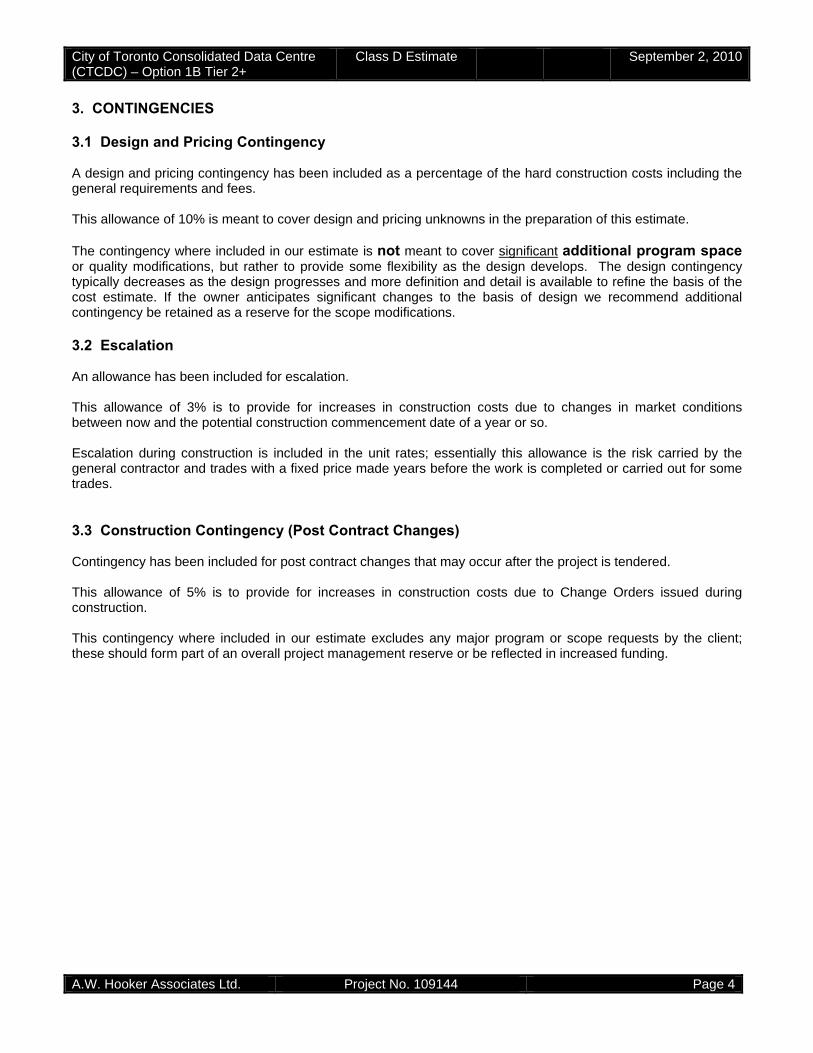
City of Toronto Consolidated Data Centre (CTCDC) – Option 1B Tier 2+
Class D Estimate September 2, 2010
A.W. Hooker Associates Ltd. Project No. 109144 Page 4
3. CONTINGENCIES 3.1 Design and Pricing Contingency A design and pricing contingency has been included as a percentage of the hard construction costs including the general requirements and fees. This allowance of 10% is meant to cover design and pricing unknowns in the preparation of this estimate. The contingency where included in our estimate is not meant to cover significant additional program space or quality modifications, but rather to provide some flexibility as the design develops. The design contingency typically decreases as the design progresses and more definition and detail is available to refine the basis of the cost estimate. If the owner anticipates significant changes to the basis of design we recommend additional contingency be retained as a reserve for the scope modifications. 3.2 Escalation An allowance has been included for escalation. This allowance of 3% is to provide for increases in construction costs due to changes in market conditions between now and the potential construction commencement date of a year or so. Escalation during construction is included in the unit rates; essentially this allowance is the risk carried by the general contractor and trades with a fixed price made years before the work is completed or carried out for some trades. 3.3 Construction Contingency (Post Contract Changes) Contingency has been included for post contract changes that may occur after the project is tendered. This allowance of 5% is to provide for increases in construction costs due to Change Orders issued during construction. This contingency where included in our estimate excludes any major program or scope requests by the client; these should form part of an overall project management reserve or be reflected in increased funding.
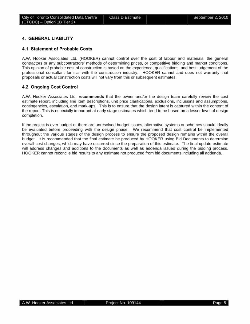
City of Toronto Consolidated Data Centre (CTCDC) – Option 1B Tier 2+
Class D Estimate September 2, 2010
A.W. Hooker Associates Ltd. Project No. 109144 Page 5
4. GENERAL LIABILITY 4.1 Statement of Probable Costs A.W. Hooker Associates Ltd. (HOOKER) cannot control over the cost of labour and materials, the general contractors or any subcontractors’ methods of determining prices, or competitive bidding and market conditions. This opinion of probable cost of construction is based on the experience, qualifications, and best judgement of the professional consultant familiar with the construction industry. HOOKER cannot and does not warranty that proposals or actual construction costs will not vary from this or subsequent estimates. 4.2 Ongoing Cost Control A.W. Hooker Associates Ltd. recommends that the owner and/or the design team carefully review the cost estimate report, including line item descriptions, unit price clarifications, exclusions, inclusions and assumptions, contingencies, escalation, and mark-ups. This is to ensure that the design intent is captured within the content of the report. This is especially important at early stage estimates which tend to be based on a lesser level of design completion. If the project is over budget or there are unresolved budget issues, alternative systems or schemes should ideally be evaluated before proceeding with the design phase. We recommend that cost control be implemented throughout the various stages of the design process to ensure the proposed design remains within the overall budget. It is recommended that the final estimate be produced by HOOKER using Bid Documents to determine overall cost changes, which may have occurred since the preparation of this estimate. The final update estimate will address changes and additions to the documents as well as addenda issued during the bidding process. HOOKER cannot reconcile bid results to any estimate not produced from bid documents including all addenda.

City of Toronto Consolidated Data Centre (CTCDC) – Option 1B Tier 2+
Class D Estimate September 2, 2010
A.W. Hooker Associates Ltd. Project No. 109144 Page 6
5. ESTIMATE SCOPE CLARIFICATIONS 5.1 List of Exclusions
1. Project Soft Costs (as described in item 2.10 above and shown on Master Estimate Summary) 2. Furniture, furnishings, and equipment (except as noted in the estimate) 3. HST 4. Abatement and handling of asbestos and other hazardous materials 5. Handling and removal of contaminated soils 6. Accelerated hard construction schedule (such as strength gain mixes in concrete) or significant
premium/shift time (if required) 7. Potential premiums associated with LEED; we believe the current estimate may be reflective of certified
level and requires review to view is Silver is achievable. 8. IT / Telecomm hardware, main switches or backbone cabling 9. Fit-up of the building beyond the 2014 white space and IT loads 10. One site storm water management 11. Bentonite Clay under the slab on grade (assumed not required) 12. Cistern Water for water closets and urinals 13. Renewable energy via solar panels 14. Deep foundation systems (estimates as per structural design brief) 15. Connection of the Fuel storage vault to the main building for access (assumed access from the exterior
of the building). 16. Green Roof (not commonly used on a data centre) 17. NOC or control equipment/tables (assumed owners furniture) 18. Technical clean 19. Incoming hydro and fibre (assumed in owner budget for hydro / fibre connection and any associated
upgrades or substations required). 20. Operating Costs (indicated as a separate price)
5.2 List of Assumptions Architectural / Structural / Landscaping:
1. Shoring is allowed in the vicinity of the fuel storage vault only 2. Placeholder allowances are included for a number of items due to the early stage of design; these are
based on comparable facilitates pending design development 3. Curtain wall area is assumed for 300m2 NOT 40% of the total cladding area as indicated in the Blast
Design Security Project report; all other cladding is based on precast cladding with louvers where required (an assumed extent)
4. We have assumed that concrete shear walls will be required in certain locations as part of the final structural design
5. The roof is assumed to be a hurricane resistant roof with interlocked pavers and tapered insulation. 6. 1000mm parapets to the perimeter of all roofs (precast cladding; with cap flashing and support steel) 7. An allowance is included for roof screening associated with the mechanical equipment (cooling tower and
load bank) 8. Partition, doors, finishes, millwork types and extent are based on previous projects with WZMH 9. An allowance is included for raised access floor in areas other than the data hall; the current program
does not define this. (Please refer to the estimate for the rooms assumed) 10. For the Tier III option two elevators are assumed (one heavy duty freight and passenger elevator) 11. The site estimate includes 1 metre of fill to the entire site; this is based on discussions with WZMH 12. Site security is based on a chain link fence with fast acting gates; we have not included an allowance for
an upgraded metal or iron fence to the street faces 13. Storm water is transferred to the existing management pond adjacent to our site; no storage is included in
the estimate 14. General requirements are based on an average percentage for data centres, the costs vary considerably
dependent on the Construction Manager selected and the deliverables required.

City of Toronto Consolidated Data Centre (CTCDC) – Option 1B Tier 2+
Class D Estimate September 2, 2010
A.W. Hooker Associates Ltd. Project No. 109144 Page 7
15. Fees are based on 2%; during a tender scenario these would probably range from 1.5-3%; recent projects have been in the 2-2.5% range.
16. F2 Tornado, Post Disaster, and Bomb Blast costs are now included; with a separate price provided on the estimate summary.
Mechanical:
17. Provisions for future growth to year 2034 have been incorporated in the infrastructure systems (headers, ductwork etc) NOT the equipment required.
18. Preaction sprinkler coverage is required in the Data Halls & UPS / Battery rooms only. Remaining building areas will be standard wet systems. Galvanized piping will be used on preaction systems.
19. Gaseous supplemental fire suppression systems are not required. 20. Condenser water circuits are closed loop filled with antifreeze glycol solution. 21. Indoor sumps for spray water to coolers will be oversized for 12 hour backup storage volume. 22. Chilled water piping to CRAC’s will contain breakdown valves and caps / valved terminations for future
CRAC or water cooled racks in the Data Halls. 23. Administration / Workstations / support and loading areas will be served by packaged commercial rooftop
HVAC units. 24. Please refer to text in estimate for more detailed inclusions and scope
Site: 25. Fire / water ring main with fire hydrants is required. Municipal street connections are not included, as
connection will be made within the property line. 26. On site back water well has been included in our estimate. 27. Storm water will discharge to adjacent existing storm water retention pond. 28. Sanitary municipal street connection is not included since it will be connected to existing stub within the
property line. 29. Below grade fuel oil storage vault for generator fuel storage.
Electrical:
30. The switchgear will be housed in the building due to the limited site area 31. Incoming power will be at 27.6KV 32. Piping and VESDA sniffer system relocated to Division 16.
General:
33. Various assumptions were made based on the design information available and our experience with projects of a similar nature. Please refer to the specific items within the estimate for the detailed assumptions made.
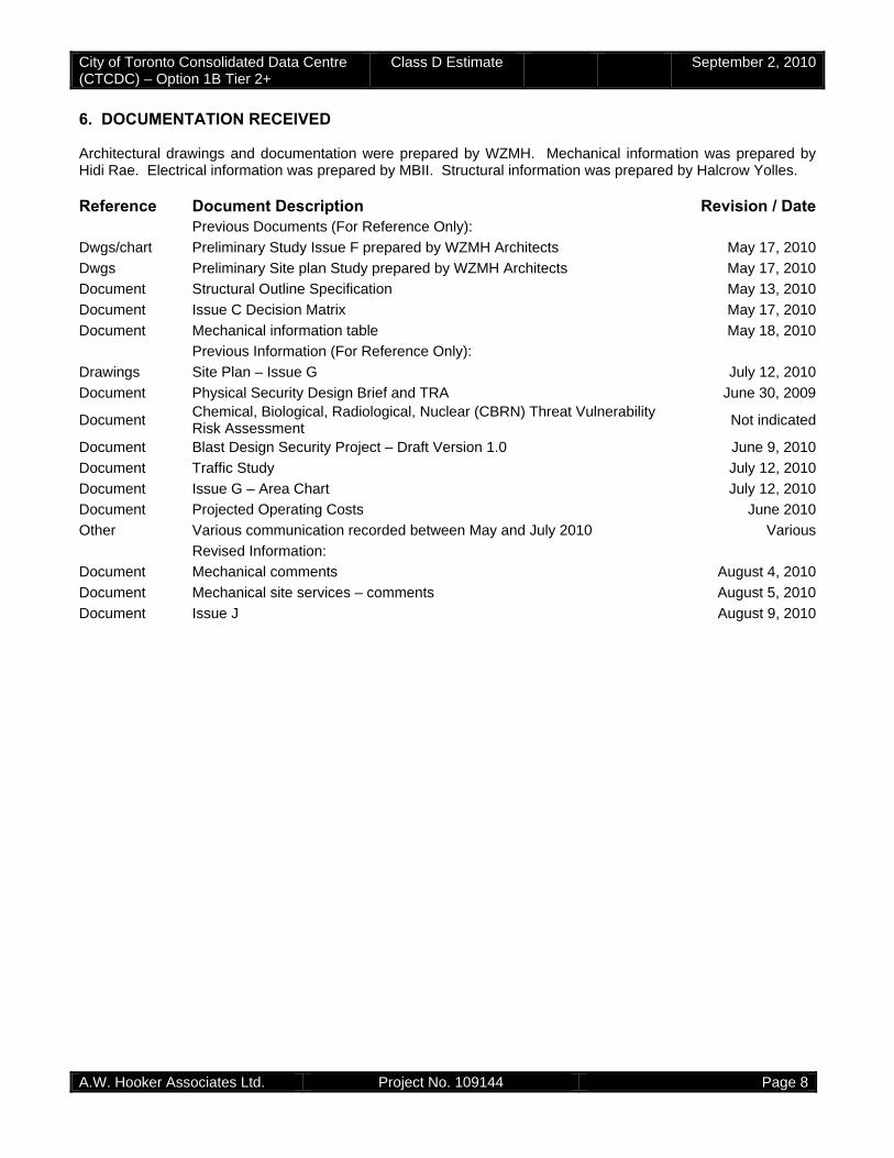
City of Toronto Consolidated Data Centre (CTCDC) – Option 1B Tier 2+
Class D Estimate September 2, 2010
A.W. Hooker Associates Ltd. Project No. 109144 Page 8
6. DOCUMENTATION RECEIVED Architectural drawings and documentation were prepared by WZMH. Mechanical information was prepared by Hidi Rae. Electrical information was prepared by MBII. Structural information was prepared by Halcrow Yolles. Reference Document Description Revision / Date Previous Documents (For Reference Only):
Dwgs/chart Preliminary Study Issue F prepared by WZMH Architects May 17, 2010
Dwgs Preliminary Site plan Study prepared by WZMH Architects May 17, 2010
Document Structural Outline Specification May 13, 2010
Document Issue C Decision Matrix May 17, 2010
Document Mechanical information table May 18, 2010
Previous Information (For Reference Only):
Drawings Site Plan – Issue G July 12, 2010
Document Physical Security Design Brief and TRA June 30, 2009
Document Chemical, Biological, Radiological, Nuclear (CBRN) Threat Vulnerability Risk Assessment
Not indicated
Document Blast Design Security Project – Draft Version 1.0 June 9, 2010
Document Traffic Study July 12, 2010
Document Issue G – Area Chart July 12, 2010
Document Projected Operating Costs June 2010
Other Various communication recorded between May and July 2010 Various
Revised Information:
Document Mechanical comments August 4, 2010
Document Mechanical site services – comments August 5, 2010
Document Issue J August 9, 2010
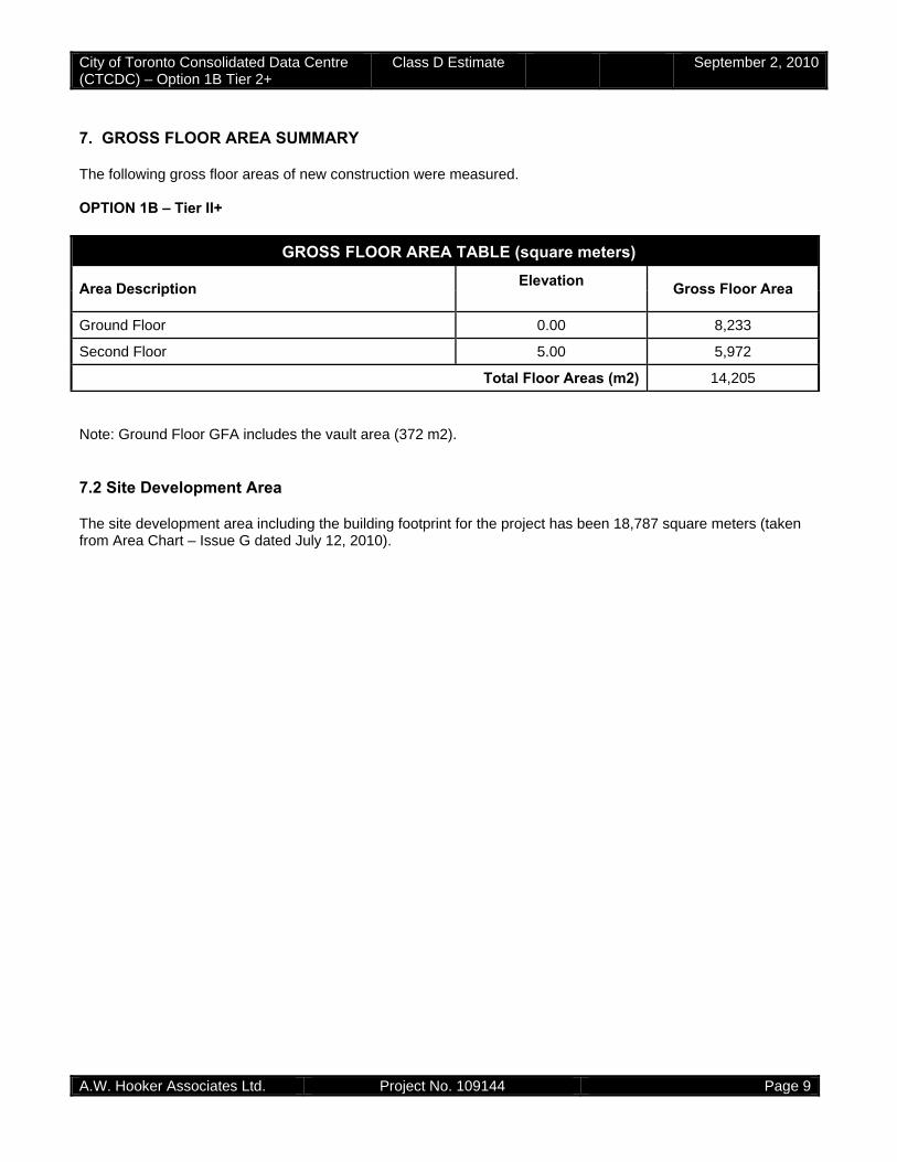
City of Toronto Consolidated Data Centre (CTCDC) – Option 1B Tier 2+
Class D Estimate September 2, 2010
A.W. Hooker Associates Ltd. Project No. 109144 Page 9
7. GROSS FLOOR AREA SUMMARY The following gross floor areas of new construction were measured. OPTION 1B – Tier II+
Note: Ground Floor GFA includes the vault area (372 m2). 7.2 Site Development Area The site development area including the building footprint for the project has been 18,787 square meters (taken from Area Chart – Issue G dated July 12, 2010).
AR GROSS FLOOR AREA TABLE (square meters)
Area Description Elevation Gross Floor Area
Ground Floor 0.00 8,233
Second Floor 5.00 5,972
Total Floor Areas (m2) 14,205
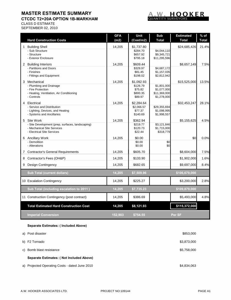
MASTER ESTIMATE SUMMARYCTCDC T2+20A OPTION 1B-MARKHAMCLASS D ESTIMATESEPTEMBER 02, 2010
GFA Unit Sub Estimated % ofHard Construction Costs (m2) (Cost/m2) Total Total Total
1 Building Shell 14,205 $1,737.80 $24,685,426 21.4%- Sub Structure $284.70 $4,044,110- Structure $657.92 $9,345,721- Exterior Enclosure $795.18 $11,295,596
2 Building Interiors 14,205 $609.44 $8,657,149 7.5%- Partitions and Doors $329.97 $4,687,172- Finishes $81.45 $1,157,035- Fittings and Equipment $198.02 $2,812,942
3 Mechanical 14,205 $1,092.93 $15,525,000 13.5%- Plumbing and Drainage $126.79 $1,801,000- Fire Protection $75.82 $1,077,000- Heating, Ventilation, Air Conditioning $800.35 $11,369,000- Controls $89.97 $1,278,000
4 Electrical 14,205 $2,284.64 $32,453,247 28.1%- Service and Distribution $2,066.57 $29,355,694- Lighting, Devices, and Heating $77.37 $1,098,995- Systems and Ancillaries $140.69 $1,998,557
5 Site Work 14,205 $362.94 $5,155,625 4.5%- Site Development (prep, surfaces, landscaping) $219.77 $3,121,846- Mechanical Site Services $120.73 $1,715,000- Electrical Site Services $22.44 $318,779
6 Ancillary Work 14,205 $0.00 $0 0.0%- Demolition $0.00 $0- Alterations $0.00 $0
$ $7 Contractor's General Requirements 8.0% 14,205 $605.70 $8,604,000 7.5%
8 Contractor's Fees (OH&P) 2.0% 14,205 $133.90 $1,902,000 1.6%
9 Design Contingency 10.0% 14,205 $682.65 $9,697,000 8.4%
Sub Total (current dollars) 14,205 $7,509.96 $106,679,000
10 Escalation Contingency 3.0% 14,205 $225.27 $3,200,000 2.8%
Sub Total (including escalation to 2011 ) 14,205 $7,735.23 $109,879,000
11 Construction Contingency (post contract) 5.0% 14,205 $386.69 $5,493,000 4.8%
Total Estimated Hard Construction Cost 14,205 $8,121.93 $115,372,000
Imperial Conversion 152,903 $754.55 Per SF
Separate Estimates: ( Included Above)
a) Post disaster $853,000
b) F2 Tornado $3,873,000
c) Bomb blast resistance $5,758,000
Separate Estimates: ( Not Included Above)
a) Projected Operating Costs - dated June 2010 $4,834,063
A.W. HOOKER ASSOCIATES LTD. PROJECT NO:109144 PAGE A1
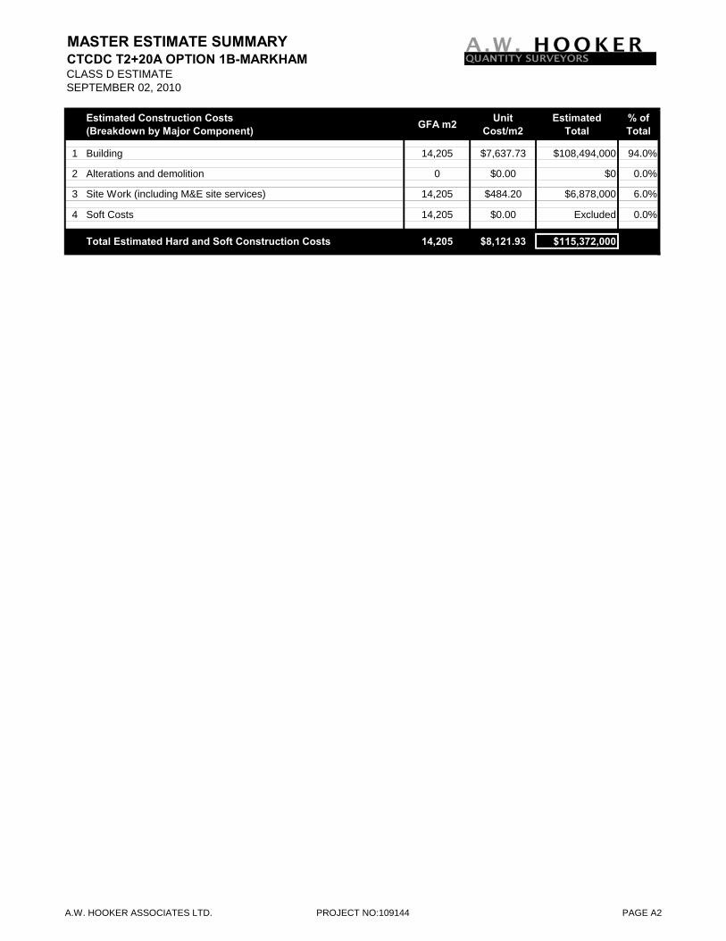
MASTER ESTIMATE SUMMARYCTCDC T2+20A OPTION 1B-MARKHAMCLASS D ESTIMATESEPTEMBER 02, 2010
Estimated Construction Costs (Breakdown by Major Component) GFA m2 Unit
Cost/m2Estimated
Total% of Total
1 Building 14,205 $7,637.73 $108,494,000 94.0%
2 Alterations and demolition 0 $0.00 $0 0.0%
3 Site Work (including M&E site services) 14,205 $484.20 $6,878,000 6.0%
4 Soft Costs 14,205 $0.00 Excluded 0.0%
Total Estimated Hard and Soft Construction Costs 14,205 $8,121.93 $115,372,000
A.W. HOOKER ASSOCIATES LTD. PROJECT NO:109144 PAGE A2
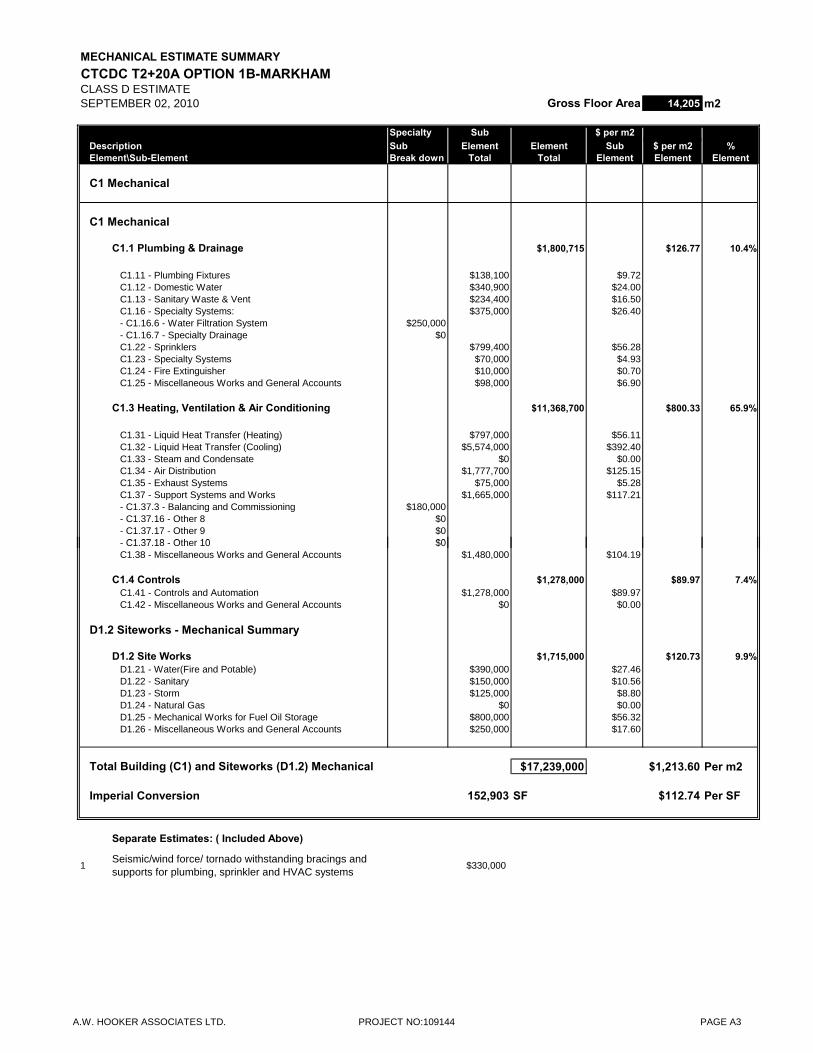
MECHANICAL ESTIMATE SUMMARYCTCDC T2+20A OPTION 1B-MARKHAMCLASS D ESTIMATESEPTEMBER 02, 2010 Gross Floor Area 14,205 m2
Specialty Sub $ per m2Description Sub Element Element Sub $ per m2 %Element\Sub-Element Break down Total Total Element Element Element
C1 Mechanical
C1 Mechanical
C1.1 Plumbing & Drainage $1,800,715 $126.77 10.4%
C1.11 - Plumbing Fixtures $138,100 $9.72C1.12 - Domestic Water $340,900 $24.00C1.13 - Sanitary Waste & Vent $234,400 $16.50C1.16 - Specialty Systems: $375,000 $26.40- C1.16.6 - Water Filtration System $250,000- C1.16.7 - Specialty Drainage $0C1.22 - Sprinklers $799,400 $56.28C1.23 - Specialty Systems $70,000 $4.93C1.24 - Fire Extinguisher $10,000 $0.70C1.25 - Miscellaneous Works and General Accounts $98,000 $6.90
C1.3 Heating, Ventilation & Air Conditioning $11,368,700 $800.33 65.9%
C1.31 - Liquid Heat Transfer (Heating) $797,000 $56.11C1.32 - Liquid Heat Transfer (Cooling) $5,574,000 $392.40C1.33 - Steam and Condensate $0 $0.00C1.34 - Air Distribution $1,777,700 $125.15C1.35 - Exhaust Systems $75,000 $5.28C1.37 - Support Systems and Works $1,665,000 $117.21- C1.37.3 - Balancing and Commissioning $180,000- C1.37.16 - Other 8 $0- C1.37.17 - Other 9 $0
C1 37 18 Oth 10 $0- C1.37.18 - Other 10 $0C1.38 - Miscellaneous Works and General Accounts $1,480,000 $104.19
C1.4 Controls $1,278,000 $89.97 7.4%C1.41 - Controls and Automation $1,278,000 $89.97C1.42 - Miscellaneous Works and General Accounts $0 $0.00
D1.2 Siteworks - Mechanical Summary
D1.2 Site Works $1,715,000 $120.73 9.9%D1.21 - Water(Fire and Potable) $390,000 $27.46D1.22 - Sanitary $150,000 $10.56D1.23 - Storm $125,000 $8.80D1.24 - Natural Gas $0 $0.00D1.25 - Mechanical Works for Fuel Oil Storage $800,000 $56.32D1.26 - Miscellaneous Works and General Accounts $250,000 $17.60
Total Building (C1) and Siteworks (D1.2) Mechanical $17,239,000 $1,213.60 Per m2
Imperial Conversion 152,903 SF $112.74 Per SF
Separate Estimates: ( Included Above)
1Seismic/wind force/ tornado withstanding bracings and supports for plumbing, sprinkler and HVAC systems
$330,000
A.W. HOOKER ASSOCIATES LTD. PROJECT NO:109144 PAGE A3
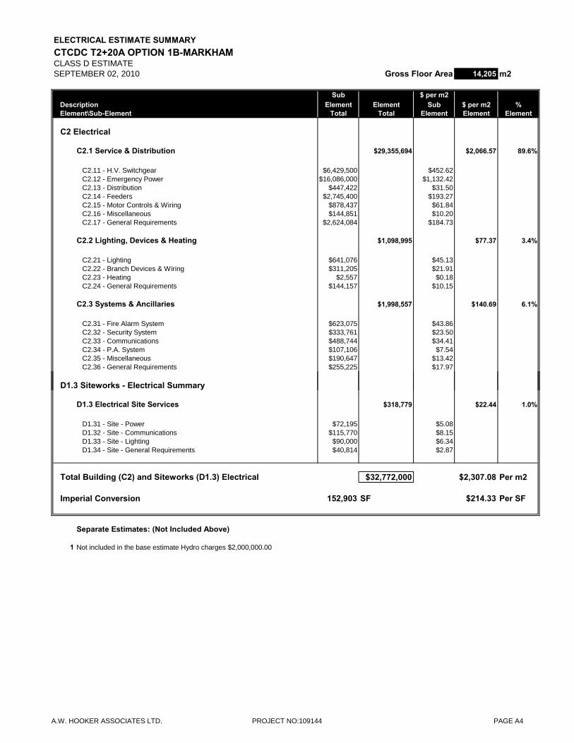
ELECTRICAL ESTIMATE SUMMARYCTCDC T2+20A OPTION 1B-MARKHAMCLASS D ESTIMATESEPTEMBER 02, 2010 Gross Floor Area 14,205 m2
Sub $ per m2Description Element Element Sub $ per m2 %Element\Sub-Element Total Total Element Element Element
C2 Electrical
C2.1 Service & Distribution $29,355,694 $2,066.57 89.6%
C2.11 - H.V. Switchgear $6,429,500 $452.62C2.12 - Emergency Power $16,086,000 $1,132.42C2.13 - Distribution $447,422 $31.50C2.14 - Feeders $2,745,400 $193.27C2.15 - Motor Controls & Wiring $878,437 $61.84C2.16 - Miscellaneous $144,851 $10.20C2.17 - General Requirements $2,624,084 $184.73
C2.2 Lighting, Devices & Heating $1,098,995 $77.37 3.4%
C2.21 - Lighting $641,076 $45.13C2.22 - Branch Devices & Wiring $311,205 $21.91C2.23 - Heating $2,557 $0.18C2.24 - General Requirements $144,157 $10.15
C2.3 Systems & Ancillaries $1,998,557 $140.69 6.1%
C2.31 - Fire Alarm System $623,075 $43.86C2.32 - Security System $333,761 $23.50C2.33 - Communications $488,744 $34.41C2.34 - P.A. System $107,106 $7.54C2.35 - Miscellaneous $190,647 $13.42C2.36 - General Requirements $255,225 $17.97
D1.3 Siteworks - Electrical Summary
D1.3 Electrical Site Services $318,779 $22.44 1.0%
D1.31 - Site - Power $72,195 $5.08D1.32 - Site - Communications $115,770 $8.15D1.33 - Site - Lighting $90,000 $6.34D1.34 - Site - General Requirements $40,814 $2.87
Total Building (C2) and Siteworks (D1.3) Electrical $32,772,000 $2,307.08 Per m2
Imperial Conversion 152,903 SF $214.33 Per SF
Separate Estimates: (Not Included Above)
1 Not included in the base estimate Hydro charges $2,000,000.00
A.W. HOOKER ASSOCIATES LTD. PROJECT NO:109144 PAGE A4
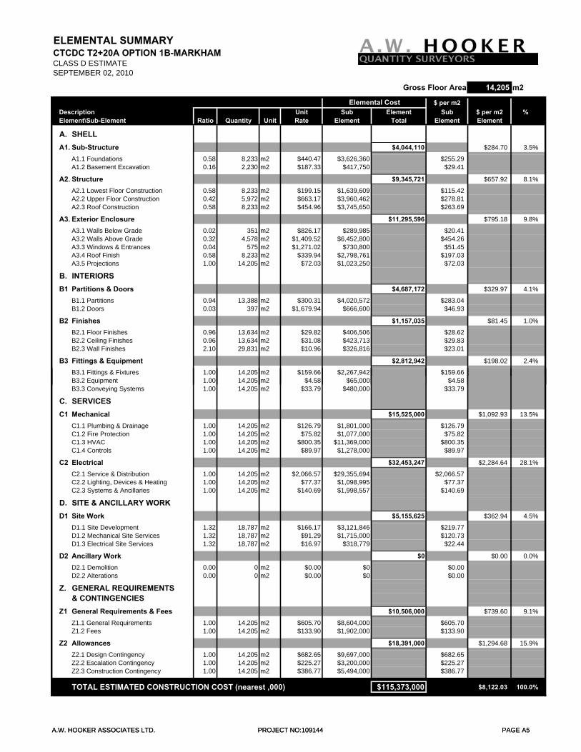
ELEMENTAL SUMMARYCTCDC T2+20A OPTION 1B-MARKHAMCLASS D ESTIMATESEPTEMBER 02, 2010
Gross Floor Area 14,205 m2
$ per m2Description Unit Sub Element Sub $ per m2 %Element\Sub-Element Ratio Quantity Unit Rate Element Total Element Element
A. SHELLA1. Sub-Structure $4,044,110 $284.70 3.5%
A1.1 Foundations 0.58 8,233 m2 $440.47 $3,626,360 $255.29A1.2 Basement Excavation 0.16 2,230 m2 $187.33 $417,750 $29.41
A2. Structure $9,345,721 $657.92 8.1%
A2.1 Lowest Floor Construction 0.58 8,233 m2 $199.15 $1,639,609 $115.42A2.2 Upper Floor Construction 0.42 5,972 m2 $663.17 $3,960,462 $278.81A2.3 Roof Construction 0.58 8,233 m2 $454.96 $3,745,650 $263.69
A3. Exterior Enclosure $11,295,596 $795.18 9.8%
A3.1 Walls Below Grade 0.02 351 m2 $826.17 $289,985 $20.41A3.2 Walls Above Grade 0.32 4,578 m2 $1,409.52 $6,452,800 $454.26A3.3 Windows & Entrances 0.04 575 m2 $1,271.02 $730,800 $51.45A3.4 Roof Finish 0.58 8,233 m2 $339.94 $2,798,761 $197.03A3.5 Projections 1.00 14,205 m2 $72.03 $1,023,250 $72.03
B. INTERIORSB1 Partitions & Doors $4,687,172 $329.97 4.1%
B1.1 Partitions 0.94 13,388 m2 $300.31 $4,020,572 $283.04B1.2 Doors 0.03 397 m2 $1,679.94 $666,600 $46.93
B2 Finishes $1,157,035 $81.45 1.0%
B2.1 Floor Finishes 0.96 13,634 m2 $29.82 $406,506 $28.62B2.2 Ceiling Finishes 0.96 13,634 m2 $31.08 $423,713 $29.83B2.3 Wall Finishes 2.10 29,831 m2 $10.96 $326,816 $23.01
B3 Fittings & Equipment $2,812,942 $198.02 2.4%
B3.1 Fittings & Fixtures 1.00 14,205 m2 $159.66 $2,267,942 $159.66
Elemental Cost
A.W. HOOKER ASSOCIATES LTD. PROJECT NO:109144 PAGE A5
B3.2 Equipment 1.00 14,205 m2 $4.58 $65,000 $4.58B3.3 Conveying Systems 1.00 14,205 m2 $33.79 $480,000 $33.79
C. SERVICESC1 Mechanical $15,525,000 $1,092.93 13.5%
C1.1 Plumbing & Drainage 1.00 14,205 m2 $126.79 $1,801,000 $126.79C1.2 Fire Protection 1.00 14,205 m2 $75.82 $1,077,000 $75.82C1.3 HVAC 1.00 14,205 m2 $800.35 $11,369,000 $800.35C1.4 Controls 1.00 14,205 m2 $89.97 $1,278,000 $89.97
C2 Electrical $32,453,247 $2,284.64 28.1%
C2.1 Service & Distribution 1.00 14,205 m2 $2,066.57 $29,355,694 $2,066.57C2.2 Lighting, Devices & Heating 1.00 14,205 m2 $77.37 $1,098,995 $77.37C2.3 Systems & Ancillaries 1.00 14,205 m2 $140.69 $1,998,557 $140.69
D. SITE & ANCILLARY WORKD1 Site Work $5,155,625 $362.94 4.5%
D1.1 Site Development 1.32 18,787 m2 $166.17 $3,121,846 $219.77D1.2 Mechanical Site Services 1.32 18,787 m2 $91.29 $1,715,000 $120.73D1.3 Electrical Site Services 1.32 18,787 m2 $16.97 $318,779 $22.44
D2 Ancillary Work $0 $0.00 0.0%
D2.1 Demolition 0.00 0 m2 $0.00 $0 $0.00D2.2 Alterations 0.00 0 m2 $0.00 $0 $0.00
Z. GENERAL REQUIREMENTS & CONTINGENCIES
Z1 General Requirements & Fees $10,506,000 $739.60 9.1%
Z1.1 General Requirements 1.00 14,205 m2 $605.70 $8,604,000 $605.70Z1.2 Fees 1.00 14,205 m2 $133.90 $1,902,000 $133.90
Z2 Allowances $18,391,000 $1,294.68 15.9%
Z2.1 Design Contingency 1.00 14,205 m2 $682.65 $9,697,000 $682.65Z2.2 Escalation Contingency 1.00 14,205 m2 $225.27 $3,200,000 $225.27Z2.3 Construction Contingency 1.00 14,205 m2 $386.77 $5,494,000 $386.77
TOTAL ESTIMATED CONSTRUCTION COST (nearest ,000) $115,373,000 $8,122.03 100.0%
A.W. HOOKER ASSOCIATES LTD. PROJECT NO:109144 PAGE A5
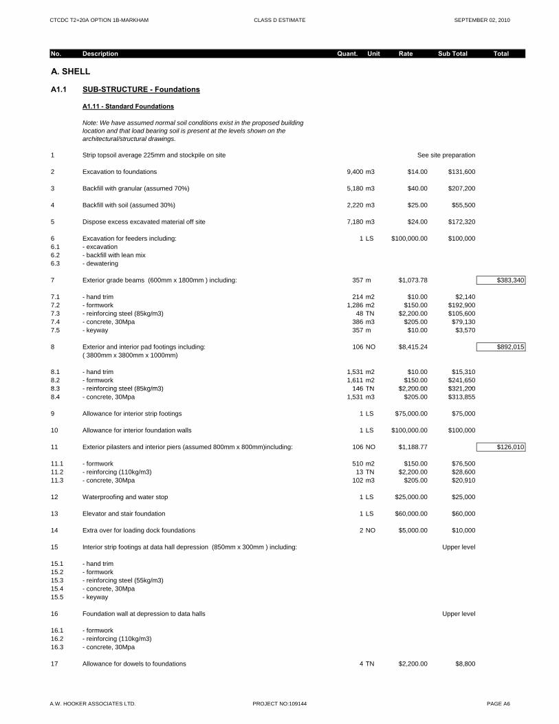
CTCDC T2+20A OPTION 1B-MARKHAM CLASS D ESTIMATE SEPTEMBER 02, 2010
No. Description Quant. Unit Rate Sub Total Total
A. SHELL
A1.1 SUB-STRUCTURE - Foundations
A1.11 - Standard Foundations
Note: We have assumed normal soil conditions exist in the proposed building location and that load bearing soil is present at the levels shown on the architectural/structural drawings.
1 Strip topsoil average 225mm and stockpile on site See site preparation
2 Excavation to foundations 9,400 m3 $14.00 $131,600
3 Backfill with granular (assumed 70%) 5,180 m3 $40.00 $207,200
4 Backfill with soil (assumed 30%) 2,220 m3 $25.00 $55,500
5 Dispose excess excavated material off site 7,180 m3 $24.00 $172,320
6 Excavation for feeders including: 1 LS $100,000.00 $100,0006.1 - excavation6.2 - backfill with lean mix6.3 - dewatering
7 Exterior grade beams (600mm x 1800mm ) including: 357 m $1,073.78 $383,340
7.1 - hand trim 214 m2 $10.00 $2,1407.2 - formwork 1,286 m2 $150.00 $192,9007.3 - reinforcing steel (85kg/m3) 48 TN $2,200.00 $105,6007.4 - concrete, 30Mpa 386 m3 $205.00 $79,1307.5 - keyway 357 m $10.00 $3,570
8 Exterior and interior pad footings including: 106 NO $8,415.24 $892,015( 3800mm x 3800mm x 1000mm)
8.1 - hand trim 1,531 m2 $10.00 $15,3108.2 - formwork 1,611 m2 $150.00 $241,6508 3 reinforcing steel (85kg/m3) 146 TN $2 200 00 $321 2008.3 - reinforcing steel (85kg/m3) 146 TN $2,200.00 $321,2008.4 - concrete, 30Mpa 1,531 m3 $205.00 $313,855
9 Allowance for interior strip footings 1 LS $75,000.00 $75,000
10 Allowance for interior foundation walls 1 LS $100,000.00 $100,000
11 Exterior pilasters and interior piers (assumed 800mm x 800mm)including: 106 NO $1,188.77 $126,010
11.1 - formwork 510 m2 $150.00 $76,50011.2 - reinforcing (110kg/m3) 13 TN $2,200.00 $28,60011.3 - concrete, 30Mpa 102 m3 $205.00 $20,910
12 Waterproofing and water stop 1 LS $25,000.00 $25,000
13 Elevator and stair foundation 1 LS $60,000.00 $60,000
14 Extra over for loading dock foundations 2 NO $5,000.00 $10,000
15 Interior strip footings at data hall depression (850mm x 300mm ) including: Upper level
15.1 - hand trim15.2 - formwork15.3 - reinforcing steel (55kg/m3)15.4 - concrete, 30Mpa15.5 - keyway
16 Foundation wall at depression to data halls Upper level
16.1 - formwork16.2 - reinforcing (110kg/m3)16.3 - concrete, 30Mpa
17 Allowance for dowels to foundations 4 TN $2,200.00 $8,800
A.W. HOOKER ASSOCIATES LTD. PROJECT NO:109144 PAGE A6
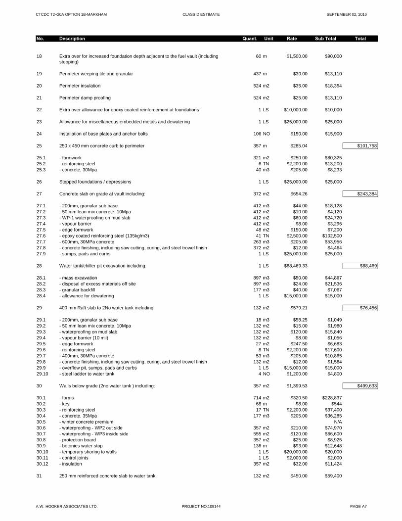
CTCDC T2+20A OPTION 1B-MARKHAM CLASS D ESTIMATE SEPTEMBER 02, 2010
No. Description Quant. Unit Rate Sub Total Total
18 Extra over for increased foundation depth adjacent to the fuel vault (including stepping)
60 m $1,500.00 $90,000
19 Perimeter weeping tile and granular 437 m $30.00 $13,110
20 Perimeter insulation 524 m2 $35.00 $18,354
21 Perimeter damp proofing 524 m2 $25.00 $13,110
22 Extra over allowance for epoxy coated reinforcement at foundations 1 LS $10,000.00 $10,000
23 Allowance for miscellaneous embedded metals and dewatering 1 LS $25,000.00 $25,000
24 Installation of base plates and anchor bolts 106 NO $150.00 $15,900
25 250 x 450 mm concrete curb to perimeter 357 m $285.04 $101,758
25.1 - formwork 321 m2 $250.00 $80,32525.2 - reinforcing steel 6 TN $2,200.00 $13,20025.3 - concrete, 30Mpa 40 m3 $205.00 $8,233
26 Stepped foundations / depressions 1 LS $25,000.00 $25,000
27 Concrete slab on grade at vault including: 372 m2 $654.26 $243,384
27.1 - 200mm, granular sub base 412 m3 $44.00 $18,12827.2 - 50 mm lean mix concrete, 10Mpa 412 m2 $10.00 $4,12027.3 - WP-1 waterproofing on mud slab 412 m2 $60.00 $24,72027.4 - vapour barrier 412 m2 $8.00 $3,29627.5 - edge formwork 48 m2 $150.00 $7,20027.6 - epoxy coated reinforcing steel (135kg/m3) 41 TN $2,500.00 $102,50027.7 - 600mm, 30MPa concrete 263 m3 $205.00 $53,95627.8 - concrete finishing, including saw cutting, curing, and steel trowel finish 372 m2 $12.00 $4,46427.9 - sumps, pads and curbs 1 LS $25,000.00 $25,000
28 Water tank/chiller pit excavation including: 1 LS $88,469.33 $88,469
28.1 - mass excavation 897 m3 $50.00 $44,86728.1 mass excavation 897 m3 $50.00 $44,86728.2 - disposal of excess materials off site 897 m3 $24.00 $21,53628.3 - granular backfill 177 m3 $40.00 $7,06728.4 - allowance for dewatering 1 LS $15,000.00 $15,000
29 400 mm Raft slab to 2No water tank including: 132 m2 $579.21 $76,456
29.1 - 200mm, granular sub base 18 m3 $58.25 $1,04929.2 - 50 mm lean mix concrete, 10Mpa 132 m2 $15.00 $1,98029.3 - waterproofing on mud slab 132 m2 $120.00 $15,84029.4 - vapour barrier (10 mil) 132 m2 $8.00 $1,05629.5 - edge formwork 27 m2 $247.50 $6,68329.6 - reinforcing steel 8 TN $2,200.00 $17,60029.7 - 400mm, 30MPa concrete 53 m3 $205.00 $10,86529.8 - concrete finishing, including saw cutting, curing, and steel trowel finish 132 m2 $12.00 $1,58429.9 - overflow pit, sumps, pads and curbs 1 LS $15,000.00 $15,00029.10 - steel ladder to water tank 4 NO $1,200.00 $4,800
30 Walls below grade (2no water tank ) including: 357 m2 $1,399.53 $499,633
30.1 - forms 714 m2 $320.50 $228,83730.2 - key 68 m $8.00 $54430.3 - reinforcing steel 17 TN $2,200.00 $37,40030.4 - concrete, 35Mpa 177 m3 $205.00 $36,28530.5 - winter concrete premium N/A30.6 - waterproofing - WP2 out side 357 m2 $210.00 $74,97030.7 - waterproofing - WP3 inside side 555 m2 $120.00 $66,60030.8 - protection board 357 m2 $25.00 $8,92530.9 - betonies water stop 136 m $93.00 $12,64830.10 - temporary shoring to walls 1 LS $20,000.00 $20,00030.11 - control joints 1 LS $2,000.00 $2,00030.12 - insulation 357 m2 $32.00 $11,424
31 250 mm reinforced concrete slab to water tank 132 m2 $450.00 $59,400
A.W. HOOKER ASSOCIATES LTD. PROJECT NO:109144 PAGE A7
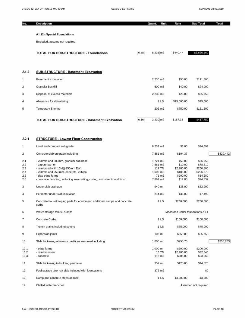
CTCDC T2+20A OPTION 1B-MARKHAM CLASS D ESTIMATE SEPTEMBER 02, 2010
No. Description Quant. Unit Rate Sub Total Total
A1.12 - Special Foundations
Excluded, assume not required
TOTAL FOR SUB-STRUCTURE - Foundations 0.58 8,233 m2 $440.47 $3,626,360
A1.2 SUB-STRUCTURE - Basement Excavation
1 Basement excavation 2,230 m3 $50.00 $111,500
2 Granular backfill 600 m3 $40.00 $24,000
3 Disposal of excess materials 2,230 m3 $25.00 $55,750
4 Allowance for dewatering 1 LS $75,000.00 $75,000
5 Temporary Shoring 202 m2 $750.00 $151,500
TOTAL FOR SUB-STRUCTURE - Basement Excavation 0.16 2,230 m2 $187.33 $417,750
A2.1 STRUCTURE - Lowest Floor Construction
1 Level and compact sub grade 8,233 m2 $3.00 $24,699
2 Concrete slab on grade including: 7,861 m2 $104.37 $820,442
2.1 - 200mm and 300mm, granular sub base 1,721 m3 $50.00 $86,0502.2 - vapour barrier 7,861 m2 $10.00 $78,6102.3 - reinforced with 15M@250mm EW 114 TN $2,200.00 $250,8002.4 - 200mm and 250 mm, concrete, 25Mpa 1,602 m3 $185.00 $296,3702.5 - slab edge forms 71 m2 $200.00 $14,2802.6 - concrete finishing, including saw cutting, curing, and steel trowel finish 7,861 m2 $12.00 $94,332
3 Under slab drainage 940 m $35.00 $32,900
4 Perimeter under slab insulation 214 m2 $35.00 $7,490
5 Concrete housekeeping pads for equipment, additional sumps and concrete curbs
1 LS $250,000 $250,000
6 Water storage tanks / sumps Measured under foundations A1.1
7 Concrete Curbs 1 LS $100,000 $100,000
8 Trench drains including covers 1 LS $75,000 $75,000
9 Expansion joints 103 m $250.00 $25,750
10 Slab thickening at interior partitions assumed including: 1,000 m $255.70 $255,703
10.1 - edge forms 1,000 m $200.00 $200,00010.2 - reinforcement 15 TN $2,200.00 $32,64010.3 - concrete 113 m3 $205.00 $23,063
11 Slab thickening to building perimeter 357 m $125.00 $44,625
12 Fuel storage tank raft slab included with foundations 372 m2 $0
13 Ramp and concrete steps at dock 1 LS $3,000.00 $3,000
14 Chilled water trenches Assumed not required
A.W. HOOKER ASSOCIATES LTD. PROJECT NO:109144 PAGE A8
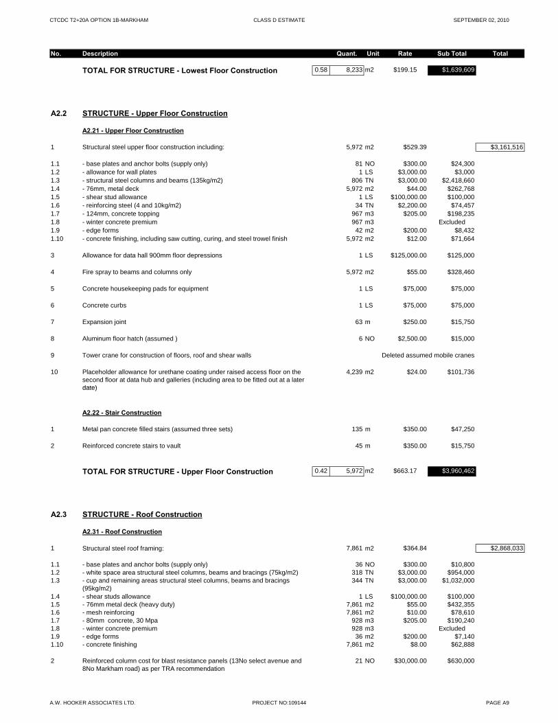
CTCDC T2+20A OPTION 1B-MARKHAM CLASS D ESTIMATE SEPTEMBER 02, 2010
No. Description Quant. Unit Rate Sub Total Total
TOTAL FOR STRUCTURE - Lowest Floor Construction 0.58 8,233 m2 $199.15 $1,639,609
A2.2 STRUCTURE - Upper Floor Construction
A2.21 - Upper Floor Construction
1 Structural steel upper floor construction including: 5,972 m2 $529.39 $3,161,516
1.1 - base plates and anchor bolts (supply only) 81 NO $300.00 $24,3001.2 - allowance for wall plates 1 LS $3,000.00 $3,0001.3 - structural steel columns and beams (135kg/m2) 806 TN $3,000.00 $2,418,6601.4 - 76mm, metal deck 5,972 m2 $44.00 $262,7681.5 - shear stud allowance 1 LS $100,000.00 $100,0001.6 - reinforcing steel (4 and 10kg/m2) 34 TN $2,200.00 $74,4571.7 - 124mm, concrete topping 967 m3 $205.00 $198,2351.8 - winter concrete premium 967 m3 Excluded1.9 - edge forms 42 m2 $200.00 $8,4321.10 - concrete finishing, including saw cutting, curing, and steel trowel finish 5,972 m2 $12.00 $71,664
3 Allowance for data hall 900mm floor depressions 1 LS $125,000.00 $125,000
4 Fire spray to beams and columns only 5,972 m2 $55.00 $328,460
5 Concrete housekeeping pads for equipment 1 LS $75,000 $75,000
6 Concrete curbs 1 LS $75,000 $75,000
7 Expansion joint 63 m $250.00 $15,750
8 Aluminum floor hatch (assumed ) 6 NO $2,500.00 $15,000
9 Tower crane for construction of floors, roof and shear walls Deleted assumed mobile cranes
10 Placeholder allowance for urethane coating under raised access floor on the second floor at data hub and galleries (including area to be fitted out at a later date)
4,239 m2 $24.00 $101,736
date)
A2.22 - Stair Construction
1 Metal pan concrete filled stairs (assumed three sets) 135 m $350.00 $47,250
2 Reinforced concrete stairs to vault 45 m $350.00 $15,750
TOTAL FOR STRUCTURE - Upper Floor Construction 0.42 5,972 m2 $663.17 $3,960,462
A2.3 STRUCTURE - Roof Construction
A2.31 - Roof Construction
1 Structural steel roof framing: 7,861 m2 $364.84 $2,868,033
1.1 - base plates and anchor bolts (supply only) 36 NO $300.00 $10,8001.2 - white space area structural steel columns, beams and bracings (75kg/m2) 318 TN $3,000.00 $954,0001.3 - cup and remaining areas structural steel columns, beams and bracings
(95kg/m2)344 TN $3,000.00 $1,032,000
1.4 - shear studs allowance 1 LS $100,000.00 $100,0001.5 - 76mm metal deck (heavy duty) 7,861 m2 $55.00 $432,3551.6 - mesh reinforcing 7,861 m2 $10.00 $78,6101.7 - 80mm concrete, 30 Mpa 928 m3 $205.00 $190,2401.8 - winter concrete premium 928 m3 Excluded1.9 - edge forms 36 m2 $200.00 $7,1401.10 - concrete finishing 7,861 m2 $8.00 $62,888
2 Reinforced column cost for blast resistance panels (13No select avenue and 8No Markham road) as per TRA recommendation
21 NO $30,000.00 $630,000
A.W. HOOKER ASSOCIATES LTD. PROJECT NO:109144 PAGE A9
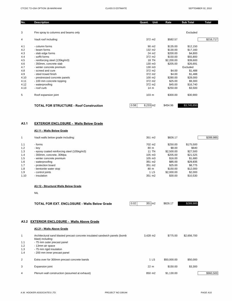
CTCDC T2+20A OPTION 1B-MARKHAM CLASS D ESTIMATE SEPTEMBER 02, 2010
No. Description Quant. Unit Rate Sub Total Total
3 Fire spray to columns and beams only Excluded
4 Vault roof including: 372 m2 $582.57 $216,717
4.1 - column forms 90 m2 $135.00 $12,1504.2 - beam forms 132 m2 $130.00 $17,1604.3 - slab edge forms 24 m2 $200.00 $4,8004.4 - soffit forms 372 m2 $150.00 $55,8004.5 - reinforcing steel (135kg/m3) 18 TN $2,200.00 $39,6004.6 - 350mm, concrete slab 130 m3 $205.00 $26,6914.7 - winter concrete premium 130 m3 Excluded4.8 - screed and cure 372 m2 $4.00 $1,4884.9 - steel trowel finish 372 m2 $4.00 $1,4884.10 - prestressed concrete panels 100 m2 $280.00 $28,0004.11 - 100 mm concrete topping 372 m2 $25.00 $9,3004.12 - waterproofing 372 m2 $45.00 $16,7404.13 - roof curb 14 m $250.00 $3,500
5 Roof expansion joint 103 m $300.00 $30,900
TOTAL FOR STRUCTURE - Roof Construction 0.58 8,233 m2 $454.96 $3,745,650
A3.1 EXTERIOR ENCLOSURE - Walls Below Grade
A3.11 - Walls Below Grade
1 Vault walls below grade including: 351 m2 $826.17 $289,985
1.1 - forms 702 m2 $250.00 $175,5001.2 - key 80 m $8.00 $6401.3 - epoxy coated reinforcing steel (105kg/m3) 11 TN $2,500.00 $27,5001.4 - 300mm, concrete, 30Mpa 105 m3 $205.00 $21,5251.5 - winter concrete premium 105 m3 $16.00 $1,6801 6 waterproofing 351 m2 $85 00 $29 8351.6 - waterproofing 351 m2 $85.00 $29,8351.7 - protection board 351 m2 $25.00 $8,7751.8 - bentonite water stop 80 m $150.00 $12,0001.9 - control joints 1 LS $2,000.00 $2,0001.10 - insulation 351 m2 $30.00 $10,530
A3.12 - Structural Walls Below Grade
NIL
TOTAL FOR EXT. ENCLOSURE - Walls Below Grade 0.02 351 m2 $826.17 $289,985
A3.2 EXTERIOR ENCLOSURE - Walls Above Grade
A3.21 - Walls Above Grade
1 Architectural sand blasted precast concrete insulated sandwich panels (bomb blast) including:
3,428 m2 $775.00 $2,656,700
1.1 - 75 mm outer precast panel1.2 - 13mm air space1.3 - 75 mm rigid insulation1.4 - 200 mm inner precast panel
2 Extra over for 300mm precast concrete bands 1 LS $50,000.00 $50,000
3 Expansion joint 22 m $150.00 $3,300
4 Plenum wall construction (assumed at exhaust) 850 m2 $1,130.00 $960,500
A.W. HOOKER ASSOCIATES LTD. PROJECT NO:109144 PAGE A10
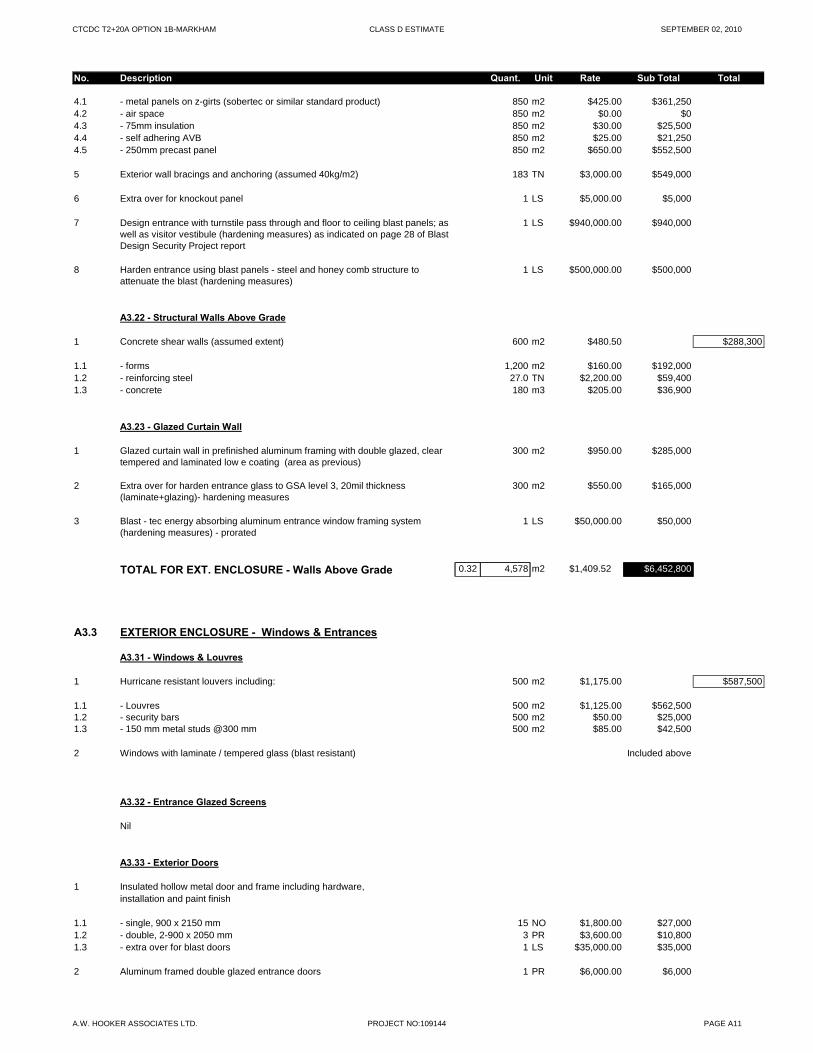
CTCDC T2+20A OPTION 1B-MARKHAM CLASS D ESTIMATE SEPTEMBER 02, 2010
No. Description Quant. Unit Rate Sub Total Total
4.1 - metal panels on z-girts (sobertec or similar standard product) 850 m2 $425.00 $361,2504.2 - air space 850 m2 $0.00 $04.3 - 75mm insulation 850 m2 $30.00 $25,5004.4 - self adhering AVB 850 m2 $25.00 $21,2504.5 - 250mm precast panel 850 m2 $650.00 $552,500
5 Exterior wall bracings and anchoring (assumed 40kg/m2) 183 TN $3,000.00 $549,000
6 Extra over for knockout panel 1 LS $5,000.00 $5,000
7 Design entrance with turnstile pass through and floor to ceiling blast panels; as well as visitor vestibule (hardening measures) as indicated on page 28 of Blast Design Security Project report
1 LS $940,000.00 $940,000
8 Harden entrance using blast panels - steel and honey comb structure to attenuate the blast (hardening measures)
1 LS $500,000.00 $500,000
A3.22 - Structural Walls Above Grade
1 Concrete shear walls (assumed extent) 600 m2 $480.50 $288,300
1.1 - forms 1,200 m2 $160.00 $192,0001.2 - reinforcing steel 27.0 TN $2,200.00 $59,4001.3 - concrete 180 m3 $205.00 $36,900
A3.23 - Glazed Curtain Wall
1 Glazed curtain wall in prefinished aluminum framing with double glazed, clear tempered and laminated low e coating (area as previous)
300 m2 $950.00 $285,000
2 Extra over for harden entrance glass to GSA level 3, 20mil thickness (laminate+glazing)- hardening measures
300 m2 $550.00 $165,000
3 Blast - tec energy absorbing aluminum entrance window framing system (hardening measures) - prorated
1 LS $50,000.00 $50,000
TOTAL FOR EXT. ENCLOSURE - Walls Above Grade 0.32 4,578 m2 $1,409.52 $6,452,800
A3.3 EXTERIOR ENCLOSURE - Windows & Entrances
A3.31 - Windows & Louvres
1 Hurricane resistant louvers including: 500 m2 $1,175.00 $587,500
1.1 - Louvres 500 m2 $1,125.00 $562,5001.2 - security bars 500 m2 $50.00 $25,0001.3 - 150 mm metal studs @300 mm 500 m2 $85.00 $42,500
2 Windows with laminate / tempered glass (blast resistant) Included above
A3.32 - Entrance Glazed Screens
Nil
A3.33 - Exterior Doors
1 Insulated hollow metal door and frame including hardware, installation and paint finish
1.1 - single, 900 x 2150 mm 15 NO $1,800.00 $27,0001.2 - double, 2-900 x 2050 mm 3 PR $3,600.00 $10,8001.3 - extra over for blast doors 1 LS $35,000.00 $35,000
2 Aluminum framed double glazed entrance doors 1 PR $6,000.00 $6,000
A.W. HOOKER ASSOCIATES LTD. PROJECT NO:109144 PAGE A11
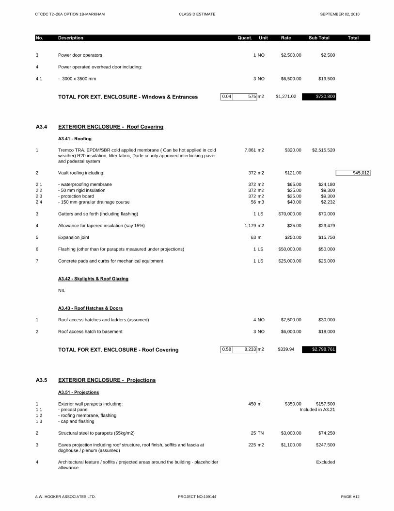
CTCDC T2+20A OPTION 1B-MARKHAM CLASS D ESTIMATE SEPTEMBER 02, 2010
No. Description Quant. Unit Rate Sub Total Total
3 Power door operators 1 NO $2,500.00 $2,500
4 Power operated overhead door including:
4.1 - 3000 x 3500 mm 3 NO $6,500.00 $19,500
TOTAL FOR EXT. ENCLOSURE - Windows & Entrances 0.04 575 m2 $1,271.02 $730,800
A3.4 EXTERIOR ENCLOSURE - Roof Covering
A3.41 - Roofing
1 Tremco TRA. EPDM/SBR cold applied membrane ( Can be hot applied in cold weather) R20 insulation, filter fabric, Dade county approved interlocking paver and pedestal system
7,861 m2 $320.00 $2,515,520
2 Vault roofing including: 372 m2 $121.00 $45,012
2.1 - waterproofing membrane 372 m2 $65.00 $24,1802.2 - 50 mm rigid insulation 372 m2 $25.00 $9,3002.3 - protection board 372 m2 $25.00 $9,3002.4 - 150 mm granular drainage course 56 m3 $40.00 $2,232
3 Gutters and so forth (including flashing) 1 LS $70,000.00 $70,000
4 Allowance for tapered insulation (say 15%) 1,179 m2 $25.00 $29,479
5 Expansion joint 63 m $250.00 $15,750
6 Flashing (other than for parapets measured under projections) 1 LS $50,000.00 $50,000
7 Concrete pads and curbs for mechanical equipment 1 LS $25,000.00 $25,000
A3.42 - Skylights & Roof Glazing
NIL
A3.43 - Roof Hatches & Doors
1 Roof access hatches and ladders (assumed) 4 NO $7,500.00 $30,000
2 Roof access hatch to basement 3 NO $6,000.00 $18,000
TOTAL FOR EXT. ENCLOSURE - Roof Covering 0.58 8,233 m2 $339.94 $2,798,761
A3.5 EXTERIOR ENCLOSURE - Projections
A3.51 - Projections
1 Exterior wall parapets including: 450 m $350.00 $157,5001.1 - precast panel Included in A3.211.2 - roofing membrane, flashing1.3 - cap and flashing
2 Structural steel to parapets (55kg/m2) 25 TN $3,000.00 $74,250
3 Eaves projection including roof structure, roof finish, soffits and fascia at doghouse / plenum (assumed)
225 m2 $1,100.00 $247,500
4 Architectural feature / soffits / projected areas around the building - placeholder allowance
Excluded
A.W. HOOKER ASSOCIATES LTD. PROJECT NO:109144 PAGE A12
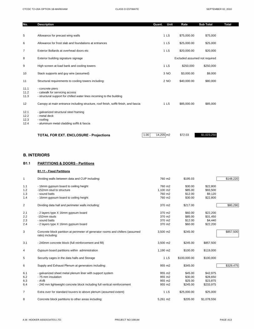
CTCDC T2+20A OPTION 1B-MARKHAM CLASS D ESTIMATE SEPTEMBER 02, 2010
No. Description Quant. Unit Rate Sub Total Total
5 Allowance for precast wing walls 1 LS $75,000.00 $75,000
6 Allowance for frost slab and foundations at entrances 1 LS $25,000.00 $25,000
7 Exterior Bollards at overhead doors etc 1 LS $20,000.00 $20,000
8 Exterior building signature signage Excluded assumed not required
9 High screen at load bank and cooling towers 1 LS $250,000 $250,000
10 Stack supports and guy wire (assumed) 3 NO $3,000.00 $9,000
11 Structural requirements to cooling towers including: 2 NO $40,000.00 $80,000
11.1 - concrete piers11.2 - catwalk for servicing access11.3 - structural support for chilled water lines incoming to the building
12 Canopy at main entrance including structure, roof finish, soffit finish, and fascia 1 LS $85,000.00 $85,000
12.1 - galvanized structural steel framing12.2 - metal deck12.3 - roofing12.4 - aluminum metal cladding soffit & fascia
TOTAL FOR EXT. ENCLOSURE - Projections 1.00 14,205 m2 $72.03 $1,023,250
B. INTERIORS
B1.1 PARTITIONS & DOORS - Partitions
B1.11 - Fixed Partitions
1 Dividing walls between data and CUP including: 760 m2 $195.03 $148,220
1.1 - 16mm gypsum board to ceiling height 760 m2 $30.00 $22,8001.2 -152mm stud to structure 1,100 m2 $85.00 $93,5001.3 - sound batts 760 m2 $12.00 $9,1201.4 - 16mm gypsum board to ceiling height 760 m2 $30.00 $22,800
2 Dividing data hall and perimeter walls including: 370 m2 $217.00 $80,290
2.1 - 2 layers type X 16mm gypsum board 370 m2 $60.00 $22,2002.2 -152mm studs 370 m2 $85.00 $31,4502.3 - sound batts 370 m2 $12.00 $4,4402.4 - 2 layers type X 16mm gypsum board 370 m2 $60.00 $22,200
3 Concrete block partition at perimeter of generator rooms and chillers (assumed ratio) including:
3,500 m2 $245.00 $857,500
3.1 - 240mm concrete block (full reinforcement and fill) 3,500 m2 $245.00 $857,500
4 Gypsum board partitions within administration 1,190 m2 $100.00 $119,000
5 Security cages in the data halls and Storage 1 LS $100,000.00 $100,000
6 Supply and Exhaust Plenum at generators including: 955 m2 $345.00 $329,475
6.1 - galvanized sheet metal plenum liner with support system 955 m2 $45.00 $42,9756.2 - 75 mm insulation 955 m2 $30.00 $28,6506.3 - AVB 955 m2 $25.00 $23,8756.4 - 240 mm lightweight concrete block including full vertical reinforcement 955 m2 $245.00 $233,975
7 Extra over for standard louvers to above plenum (assumed extent) 1 LS $25,000.00 $25,000
8 Concrete block partitions to other areas including: 5,261 m2 $205.00 $1,078,556
A.W. HOOKER ASSOCIATES LTD. PROJECT NO:109144 PAGE A13
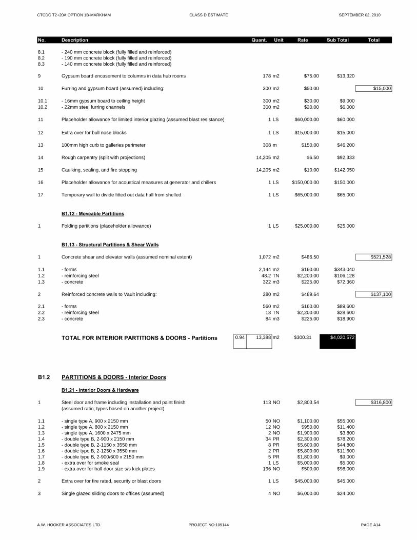
CTCDC T2+20A OPTION 1B-MARKHAM CLASS D ESTIMATE SEPTEMBER 02, 2010
No. Description Quant. Unit Rate Sub Total Total
8.1 - 240 mm concrete block (fully filled and reinforced)8.2 - 190 mm concrete block (fully filled and reinforced)8.3 - 140 mm concrete block (fully filled and reinforced)
9 Gypsum board encasement to columns in data hub rooms 178 m2 $75.00 $13,320
10 Furring and gypsum board (assumed) including: 300 m2 $50.00 $15,000
10.1 - 16mm gypsum board to ceiling height 300 m2 $30.00 $9,00010.2 - 22mm steel furring channels 300 m2 $20.00 $6,000
11 Placeholder allowance for limited interior glazing (assumed blast resistance) 1 LS $60,000.00 $60,000
12 Extra over for bull nose blocks 1 LS $15,000.00 $15,000
13 100mm high curb to galleries perimeter 308 m $150.00 $46,200
14 Rough carpentry (split with projections) 14,205 m2 $6.50 $92,333
15 Caulking, sealing, and fire stopping 14,205 m2 $10.00 $142,050
16 Placeholder allowance for acoustical measures at generator and chillers 1 LS $150,000.00 $150,000
17 Temporary wall to divide fitted out data hall from shelled 1 LS $65,000.00 $65,000
B1.12 - Moveable Partitions
1 Folding partitions (placeholder allowance) 1 LS $25,000.00 $25,000
B1.13 - Structural Partitions & Shear Walls
1 Concrete shear and elevator walls (assumed nominal extent) 1,072 m2 $486.50 $521,528
1.1 - forms 2,144 m2 $160.00 $343,0401.2 - reinforcing steel 48.2 TN $2,200.00 $106,1281.3 - concrete 322 m3 $225.00 $72,360
2 Reinforced concrete walls to Vault including: 280 m2 $489.64 $137,100
2.1 - forms 560 m2 $160.00 $89,6002.2 - reinforcing steel 13 TN $2,200.00 $28,6002.3 - concrete 84 m3 $225.00 $18,900
TOTAL FOR INTERIOR PARTITIONS & DOORS - Partitions 0.94 13,388 m2 $300.31 $4,020,572
B1.2 PARTITIONS & DOORS - Interior Doors
B1.21 - Interior Doors & Hardware
1 Steel door and frame including installation and paint finish 113 NO $2,803.54 $316,800(assumed ratio; types based on another project)
1.1 - single type A, 900 x 2150 mm 50 NO $1,100.00 $55,0001.2 - single type A, 800 x 2150 mm 12 NO $950.00 $11,4001.3 - single type A, 1600 x 2475 mm 2 NO $1,900.00 $3,8001.4 - double type B, 2-900 x 2150 mm 34 PR $2,300.00 $78,2001.5 - double type B, 2-1150 x 3550 mm 8 PR $5,600.00 $44,8001.6 - double type B, 2-1250 x 3550 mm 2 PR $5,800.00 $11,6001.7 - double type B, 2-900/600 x 2150 mm 5 PR $1,800.00 $9,0001.8 - extra over for smoke seal 1 LS $5,000.00 $5,0001.9 - extra over for half door size s/s kick plates 196 NO $500.00 $98,000
2 Extra over for fire rated, security or blast doors 1 LS $45,000.00 $45,000
3 Single glazed sliding doors to offices (assumed) 4 NO $6,000.00 $24,000
A.W. HOOKER ASSOCIATES LTD. PROJECT NO:109144 PAGE A14
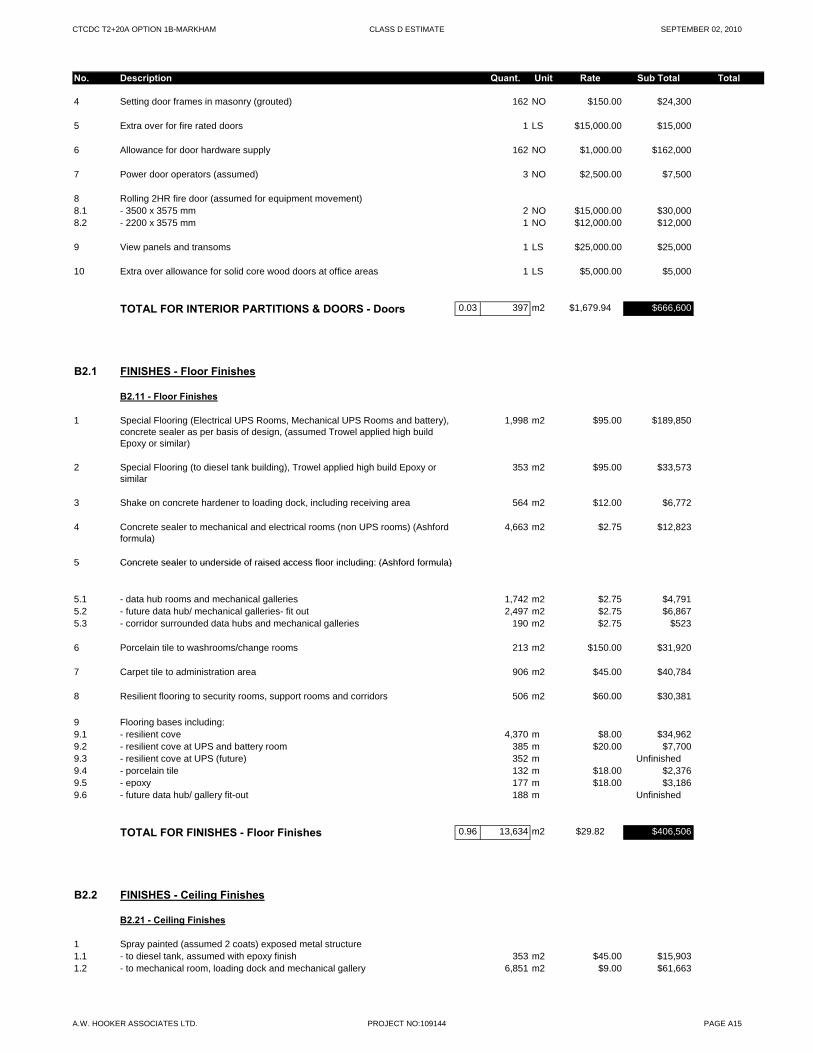
CTCDC T2+20A OPTION 1B-MARKHAM CLASS D ESTIMATE SEPTEMBER 02, 2010
No. Description Quant. Unit Rate Sub Total Total
4 Setting door frames in masonry (grouted) 162 NO $150.00 $24,300
5 Extra over for fire rated doors 1 LS $15,000.00 $15,000
6 Allowance for door hardware supply 162 NO $1,000.00 $162,000
7 Power door operators (assumed) 3 NO $2,500.00 $7,500
8 Rolling 2HR fire door (assumed for equipment movement)8.1 - 3500 x 3575 mm 2 NO $15,000.00 $30,0008.2 - 2200 x 3575 mm 1 NO $12,000.00 $12,000
9 View panels and transoms 1 LS $25,000.00 $25,000
10 Extra over allowance for solid core wood doors at office areas 1 LS $5,000.00 $5,000
TOTAL FOR INTERIOR PARTITIONS & DOORS - Doors 0.03 397 m2 $1,679.94 $666,600
B2.1 FINISHES - Floor Finishes
B2.11 - Floor Finishes
1 Special Flooring (Electrical UPS Rooms, Mechanical UPS Rooms and battery), concrete sealer as per basis of design, (assumed Trowel applied high build Epoxy or similar)
1,998 m2 $95.00 $189,850
2 Special Flooring (to diesel tank building), Trowel applied high build Epoxy or similar
353 m2 $95.00 $33,573
3 Shake on concrete hardener to loading dock, including receiving area 564 m2 $12.00 $6,772
4 Concrete sealer to mechanical and electrical rooms (non UPS rooms) (Ashford formula)
4,663 m2 $2.75 $12,823
5 Concrete sealer to underside of raised access floor including: (Ashford formula)5 Concrete sealer to underside of raised access floor including: (Ashford formula)
5.1 - data hub rooms and mechanical galleries 1,742 m2 $2.75 $4,7915.2 - future data hub/ mechanical galleries- fit out 2,497 m2 $2.75 $6,8675.3 - corridor surrounded data hubs and mechanical galleries 190 m2 $2.75 $523
6 Porcelain tile to washrooms/change rooms 213 m2 $150.00 $31,920
7 Carpet tile to administration area 906 m2 $45.00 $40,784
8 Resilient flooring to security rooms, support rooms and corridors 506 m2 $60.00 $30,381
9 Flooring bases including:9.1 - resilient cove 4,370 m $8.00 $34,9629.2 - resilient cove at UPS and battery room 385 m $20.00 $7,7009.3 - resilient cove at UPS (future) 352 m Unfinished9.4 - porcelain tile 132 m $18.00 $2,3769.5 - epoxy 177 m $18.00 $3,1869.6 - future data hub/ gallery fit-out 188 m Unfinished
TOTAL FOR FINISHES - Floor Finishes 0.96 13,634 m2 $29.82 $406,506
B2.2 FINISHES - Ceiling Finishes
B2.21 - Ceiling Finishes
1 Spray painted (assumed 2 coats) exposed metal structure1.1 - to diesel tank, assumed with epoxy finish 353 m2 $45.00 $15,9031.2 - to mechanical room, loading dock and mechanical gallery 6,851 m2 $9.00 $61,663
A.W. HOOKER ASSOCIATES LTD. PROJECT NO:109144 PAGE A15
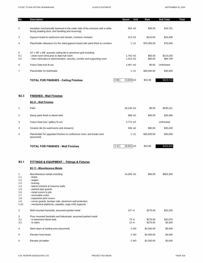
CTCDC T2+20A OPTION 1B-MARKHAM CLASS D ESTIMATE SEPTEMBER 02, 2010
No. Description Quant. Unit Rate Sub Total Total
2 Insulation mechanically fastened to the under side of the structure with a white facing (loading dock, and handling and receiving)
564 m2 $35.00 $19,751
3 Gypsum board to washroom and shower, moisture resistant 213 m2 $110.00 $23,408
4 Placeholder allowance for fire rated gypsum board with paint finish to corridors 1 LS $75,000.00 $75,000
5 24" x 48" x 5/8" acoustic ceiling tile in aluminum grid including: 5.1 - clean room clima plus to data hub room 1,742 m2 $65.00 $113,2305.2 - mars clima plus to administration, security, corridor and supporting room 1,413 m2 $60.00 $84,759
6 Future Data hub fit-out 2,497 m2 $0.00 Unfinished
7 Placeholder for bulkheads 1 LS $30,000.00 $30,000
TOTAL FOR FINISHES - Ceiling Finishes 0.96 13,634 m2 $31.08 $423,713
B2.3 FINISHES - Wall Finishes
B2.31 - Wall Finishes
1 Paint 26,135 m2 $9.00 $235,211
2 Epoxy paint finish to diesel tank 586 m2 $45.00 $26,366
3 Future Data hub / gallery fit-out 2,774 m2 Unfinished
4 Ceramic tile (to washrooms and showers) 336 m2 $90.00 $30,240
5 Placeholder for upgraded finishes to conference room, and break room (assumed)
1 LS $35,000.00 $35,000
TOTAL FOR FINISHES - Wall Finishes 2.10 29,831 m2 $10.96 $326,816
B3.1 FITTINGS & EQUIPMENT - Fittings & Fixtures
B3.11 - Miscellaneous Metals
1 Miscellaneous metals including 14,205 m2 $60.00 $852,3001.1 - lintels1.2 - angles1.3 - bracing1.4 - lateral restraint at masonry walls1.5 - painted pipe guards 1.6 - metal covers to pits1.7 - removable curbs1.8 - expansion joint covers1.9 - corner guards, bumper rails, aluminum wall protection1.10 - mechanical platforms, catwalks, large HSS supports
2 Wall mounted handrails, assumed painted metal 127 m $175.00 $22,225
3 Floor mounted handrails and balustrade, assumed painted metal3.1 - to basement diesel tank 73 m $275.00 $20,0753.2 - to stairs 12 m $275.00 $3,300
4 Steel steps at loading area (assumed) 2 NO $2,500.00 $5,000
5 Elevator hoist beam 2 NO $2,000.00 $4,000
6 Elevator pit ladder 2 NO $1,500.00 $3,000
A.W. HOOKER ASSOCIATES LTD. PROJECT NO:109144 PAGE A16
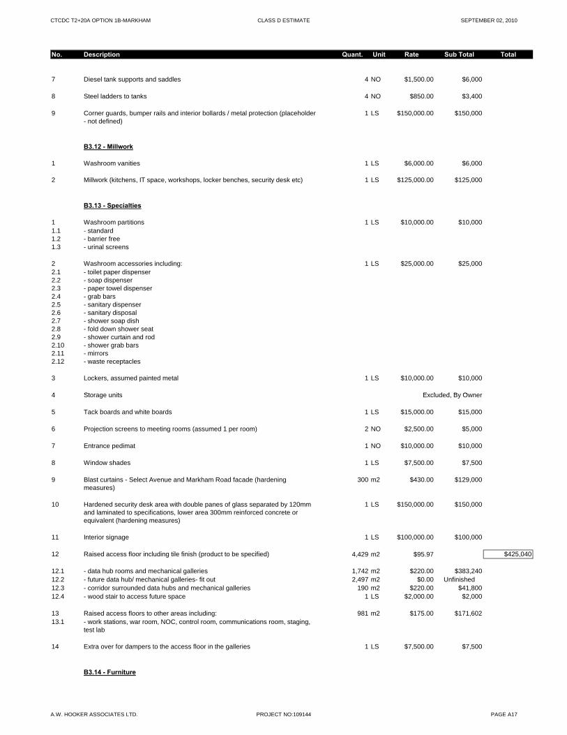
CTCDC T2+20A OPTION 1B-MARKHAM CLASS D ESTIMATE SEPTEMBER 02, 2010
No. Description Quant. Unit Rate Sub Total Total
7 Diesel tank supports and saddles 4 NO $1,500.00 $6,000
8 Steel ladders to tanks 4 NO $850.00 $3,400
9 Corner guards, bumper rails and interior bollards / metal protection (placeholder - not defined)
1 LS $150,000.00 $150,000
B3.12 - Millwork
1 Washroom vanities 1 LS $6,000.00 $6,000
2 Millwork (kitchens, IT space, workshops, locker benches, security desk etc) 1 LS $125,000.00 $125,000
B3.13 - Specialties
1 Washroom partitions 1 LS $10,000.00 $10,0001.1 - standard1.2 - barrier free1.3 - urinal screens
2 Washroom accessories including: 1 LS $25,000.00 $25,0002.1 - toilet paper dispenser2.2 - soap dispenser2.3 - paper towel dispenser2.4 - grab bars 2.5 - sanitary dispenser2.6 - sanitary disposal2.7 - shower soap dish2.8 - fold down shower seat 2.9 - shower curtain and rod2.10 - shower grab bars2.11 - mirrors2.12 - waste receptacles
3 Lockers, assumed painted metal 1 LS $10,000.00 $10,000
4 Storage units Excluded By Owner4 Storage units Excluded, By Owner
5 Tack boards and white boards 1 LS $15,000.00 $15,000
6 Projection screens to meeting rooms (assumed 1 per room) 2 NO $2,500.00 $5,000
7 Entrance pedimat 1 NO $10,000.00 $10,000
8 Window shades 1 LS $7,500.00 $7,500
9 Blast curtains - Select Avenue and Markham Road facade (hardening measures)
300 m2 $430.00 $129,000
10 Hardened security desk area with double panes of glass separated by 120mm and laminated to specifications, lower area 300mm reinforced concrete or equivalent (hardening measures)
1 LS $150,000.00 $150,000
11 Interior signage 1 LS $100,000.00 $100,000
12 Raised access floor including tile finish (product to be specified) 4,429 m2 $95.97 $425,040
12.1 - data hub rooms and mechanical galleries 1,742 m2 $220.00 $383,24012.2 - future data hub/ mechanical galleries- fit out 2,497 m2 $0.00 Unfinished12.3 - corridor surrounded data hubs and mechanical galleries 190 m2 $220.00 $41,80012.4 - wood stair to access future space 1 LS $2,000.00 $2,000
13 Raised access floors to other areas including: 981 m2 $175.00 $171,60213.1 - work stations, war room, NOC, control room, communications room, staging,
test lab
14 Extra over for dampers to the access floor in the galleries 1 LS $7,500.00 $7,500
B3.14 - Furniture
A.W. HOOKER ASSOCIATES LTD. PROJECT NO:109144 PAGE A17
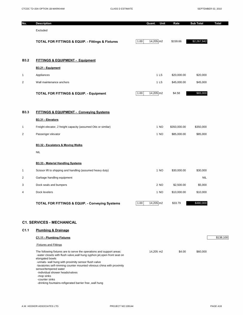
CTCDC T2+20A OPTION 1B-MARKHAM CLASS D ESTIMATE SEPTEMBER 02, 2010
No. Description Quant. Unit Rate Sub Total Total
Excluded
TOTAL FOR FITTINGS & EQUIP. - Fittings & Fixtures 1.00 14,205 m2 $159.66 $2,267,942
B3.2 FITTINGS & EQUIPMENT - Equipment
B3.21 - Equipment
1 Appliances 1 LS $20,000.00 $20,000
2 Wall maintenance anchors 1 LS $45,000.00 $45,000
TOTAL FOR FITTINGS & EQUIP. - Equipment 1.00 14,205 m2 $4.58 $65,000
B3.3 FITTINGS & EQUIPMENT - Conveying Systems
B3.31 - Elevators
1 Freight elevator, 2 freight capacity (assumed Otis or similar) 1 NO $350,000.00 $350,000
2 Passenger elevator 1 NO $85,000.00 $85,000
B3.32 - Escalators & Moving Walks
NIL
B3.33 - Material Handling Systems
1 Scissor lift to shipping and handling (assumed heavy duty) 1 NO $30,000.00 $30,000
2 Garbage handling equipment NIL
3 Dock seals and bumpers 2 NO $2,500.00 $5,000
4 Dock levelers 1 NO $10,000.00 $10,000
TOTAL FOR FITTINGS & EQUIP. - Conveying Systems 1.00 14,205 m2 $33.79 $480,000
C1. SERVICES - MECHANICAL
C1.1 Plumbing & Drainage
C1.11 - Plumbing Fixtures $138,100
Fixtures and Fittings
The following fixtures are to serve the operations and support areas: 14,205 m2 $4.00 $60,000 -water closets with flush valve,wall hung syphon jet,open front seat on elongated bowls -urinals- wall hung with proximity sensor flush valve -lavatories self-rimming counter mounted vitreous china with proximity sensor/tempered water -individual shower heads/valves -mop sinks -counter sinks -drinking fountains-refigerated barrier free ,wall hung
A.W. HOOKER ASSOCIATES LTD. PROJECT NO:109144 PAGE A18
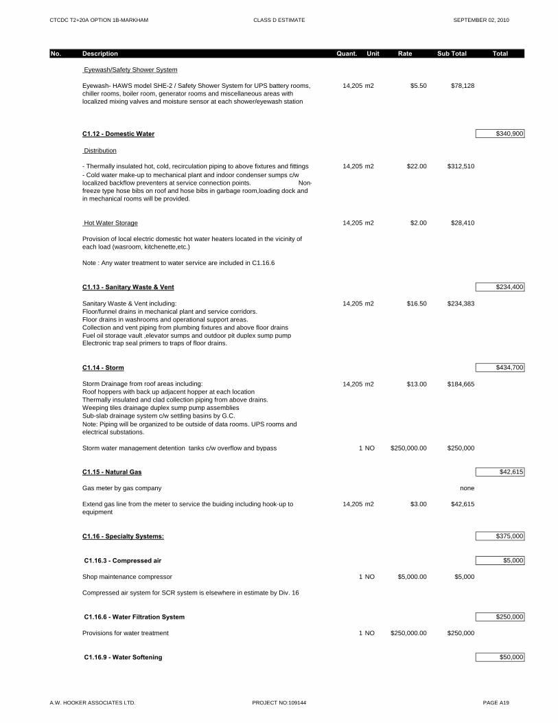
CTCDC T2+20A OPTION 1B-MARKHAM CLASS D ESTIMATE SEPTEMBER 02, 2010
No. Description Quant. Unit Rate Sub Total Total
Eyewash/Safety Shower System
Eyewash- HAWS model SHE-2 / Safety Shower System for UPS battery rooms, chiller rooms, boiler room, generator rooms and miscellaneous areas with localized mixing valves and moisture sensor at each shower/eyewash station
14,205 m2 $5.50 $78,128
C1.12 - Domestic Water $340,900
Distribution
- Thermally insulated hot, cold, recirculation piping to above fixtures and fittings 14,205 m2 $22.00 $312,510- Cold water make-up to mechanical plant and indoor condenser sumps c/w localized backflow preventers at service connection points. Non-freeze type hose bibs on roof and hose bibs in garbage room,loading dock and in mechanical rooms will be provided.
Hot Water Storage 14,205 m2 $2.00 $28,410
Provision of local electric domestic hot water heaters located in the vicinity of each load (wasroom, kitchenette,etc.)
Note : Any water treatment to water service are included in C1.16.6
C1.13 - Sanitary Waste & Vent $234,400
Sanitary Waste & Vent including: 14,205 m2 $16.50 $234,383Floor/funnel drains in mechanical plant and service corridors.Floor drains in washrooms and operational support areas.Collection and vent piping from plumbing fixtures and above floor drainsFuel oil storage vault ,elevator sumps and outdoor pit duplex sump pump Electronic trap seal primers to traps of floor drains.
C1.14 - Storm $434,700
Storm Drainage from roof areas including: 14,205 m2 $13.00 $184,665g g , $ $ ,Roof hoppers with back up adjacent hopper at each locationThermally insulated and clad collection piping from above drains.Weeping tiles drainage duplex sump pump assembliesSub-slab drainage system c/w settling basins by G.C.Note: Piping will be organized to be outside of data rooms. UPS rooms and electrical substations.
Storm water management detention tanks c/w overflow and bypass 1 NO $250,000.00 $250,000
C1.15 - Natural Gas $42,615
Gas meter by gas company none
Extend gas line from the meter to service the buiding including hook-up to equipment
14,205 m2 $3.00 $42,615
C1.16 - Specialty Systems: $375,000
C1.16.3 - Compressed air $5,000
Shop maintenance compressor 1 NO $5,000.00 $5,000
Compressed air system for SCR system is elsewhere in estimate by Div. 16
C1.16.6 - Water Filtration System $250,000
Provisions for water treatment 1 NO $250,000.00 $250,000
C1.16.9 - Water Softening $50,000
A.W. HOOKER ASSOCIATES LTD. PROJECT NO:109144 PAGE A19
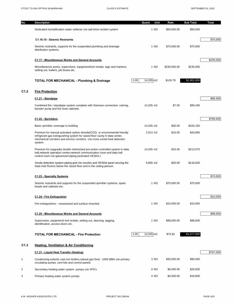
CTCDC T2+20A OPTION 1B-MARKHAM CLASS D ESTIMATE SEPTEMBER 02, 2010
No. Description Quant. Unit Rate Sub Total Total
Dedicated humidification water softener c/w salt brine reclaim system 1 NO $50,000.00 $50,000
C1.16.10 - Seismic Restraints $70,000
Seismic restraints, supports for the suspended plumbing and drainage distribution systems.
1 NO $70,000.00 $70,000
C1.17 - Miscellaneous Works and General Accounts $235,000
Miscellaneous works, supervision, equipment/tool rentals, tags and markers, setting out, trailers, job boxes etc.
1 NO $235,000.00 $235,000
TOTAL FOR MECHANICAL - Plumbing & Drainage 1.00 14,205 m2 $126.79 $1,801,000
C1.2 Fire Protection
C1.21 - Standpipe $99,400
Combined fire / standpipe system complete with Siamese connection, valving, booster pump and fire hose cabinets.
14,205 m2 $7.00 $99,435
C1.22 - Sprinklers $799,400
Basic sprinkler coverage to building 14,205 m2 $30.00 $426,150
Premium for manual activated carbon dioxide(CO2) or environmental friendly refrigerant gas extinguishing system for raised floor cavity in data center, mechanical corridors and service corridors c/w cross zoned heat detection system.
2,913 m2 $15.00 $43,695
Premium for (upgrade) double interlocked pre-action controlled system in data hall,network operation centre,network communication room and data hall control room c/w galvanized piping.(activated VESDA )
14,205 m2 $15.00 $213,075
Vesda detection system piping grid c/w nozzles and VESDA panel serving the 5,826 m2 $20.00 $116,520Vesda detection system piping grid c/w nozzles and VESDA panel serving the Data Hub Rooms below the raised floor and in the ceiling plenum.
5,826 m2 $20.00 $116,520
C1.23 - Specialty Systems $70,000
Seismic restraints and supports for the suspended sprinkler systems, spare heads and cabinets etc.
1 NO $70,000.00 $70,000
C1.24 - Fire Extinguisher $10,000
Fire extinguishers - reassessed and surface mounted. 1 NO $10,000.00 $10,000
C1.25 - Miscellaneous Works and General Accounts $98,000
Supervision, equipment/ tool rentals, setting out, sleeving, tagging, identification, access doors etc.
1 NO $98,000.00 $98,000
TOTAL FOR MECHANICAL - Fire Protection 1.00 14,205 m2 $75.82 $1,077,000
C1.3 Heating, Ventilation & Air Conditioning
C1.31 - Liquid Heat Transfer (Heating) $797,000
1 Condensing eutectic cast iron boilers,natural gas fired - 1000 MBH c/w primary circulating pumps ,vent kits and control panels
3 NO $30,000.00 $90,000
2 Secondary heating water system pumps c/w VFD's 4 NO $6,500.00 $26,000
3 Primary heating water system pumps 4 NO $4,500.00 $18,000
A.W. HOOKER ASSOCIATES LTD. PROJECT NO:109144 PAGE A20
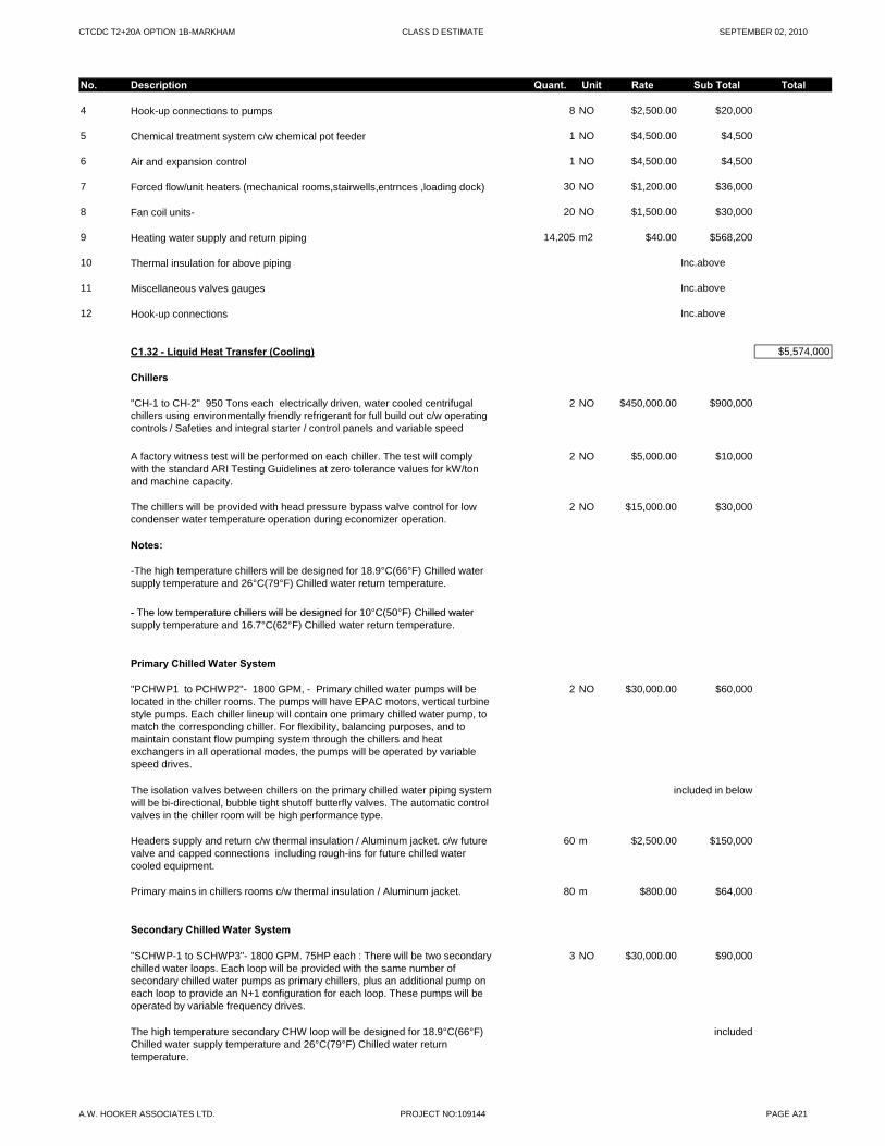
CTCDC T2+20A OPTION 1B-MARKHAM CLASS D ESTIMATE SEPTEMBER 02, 2010
No. Description Quant. Unit Rate Sub Total Total
4 Hook-up connections to pumps 8 NO $2,500.00 $20,000
5 Chemical treatment system c/w chemical pot feeder 1 NO $4,500.00 $4,500
6 Air and expansion control 1 NO $4,500.00 $4,500
7 Forced flow/unit heaters (mechanical rooms,stairwells,entrnces ,loading dock) 30 NO $1,200.00 $36,000
8 Fan coil units- 20 NO $1,500.00 $30,000
9 Heating water supply and return piping 14,205 m2 $40.00 $568,200
10 Thermal insulation for above piping Inc.above
11 Miscellaneous valves gauges Inc.above
12 Hook-up connections Inc.above
C1.32 - Liquid Heat Transfer (Cooling) $5,574,000
Chillers
"CH-1 to CH-2" 950 Tons each electrically driven, water cooled centrifugal chillers using environmentally friendly refrigerant for full build out c/w operating controls / Safeties and integral starter / control panels and variable speed d i
2 NO $450,000.00 $900,000
A factory witness test will be performed on each chiller. The test will comply with the standard ARI Testing Guidelines at zero tolerance values for kW/ton and machine capacity.
2 NO $5,000.00 $10,000
The chillers will be provided with head pressure bypass valve control for low condenser water temperature operation during economizer operation.
2 NO $15,000.00 $30,000
Notes:
-The high temperature chillers will be designed for 18.9°C(66°F) Chilled water supply temperature and 26°C(79°F) Chilled water return temperature.
- The low temperature chillers will be designed for 10°C(50°F) Chilled water- The low temperature chillers will be designed for 10 C(50 F) Chilled water supply temperature and 16.7°C(62°F) Chilled water return temperature.
Primary Chilled Water System
"PCHWP1 to PCHWP2"- 1800 GPM, - Primary chilled water pumps will be located in the chiller rooms. The pumps will have EPAC motors, vertical turbine style pumps. Each chiller lineup will contain one primary chilled water pump, to match the corresponding chiller. For flexibility, balancing purposes, and to maintain constant flow pumping system through the chillers and heat exchangers in all operational modes, the pumps will be operated by variable speed drives.
2 NO $30,000.00 $60,000
The isolation valves between chillers on the primary chilled water piping system will be bi-directional, bubble tight shutoff butterfly valves. The automatic control valves in the chiller room will be high performance type.
included in below
Headers supply and return c/w thermal insulation / Aluminum jacket. c/w future valve and capped connections including rough-ins for future chilled water cooled equipment.
60 m $2,500.00 $150,000
Primary mains in chillers rooms c/w thermal insulation / Aluminum jacket. 80 m $800.00 $64,000
Secondary Chilled Water System
"SCHWP-1 to SCHWP3"- 1800 GPM. 75HP each : There will be two secondary chilled water loops. Each loop will be provided with the same number of secondary chilled water pumps as primary chillers, plus an additional pump on each loop to provide an N+1 configuration for each loop. These pumps will be operated by variable frequency drives.
3 NO $30,000.00 $90,000
The high temperature secondary CHW loop will be designed for 18.9°C(66°F) Chilled water supply temperature and 26°C(79°F) Chilled water return temperature.
included
A.W. HOOKER ASSOCIATES LTD. PROJECT NO:109144 PAGE A21
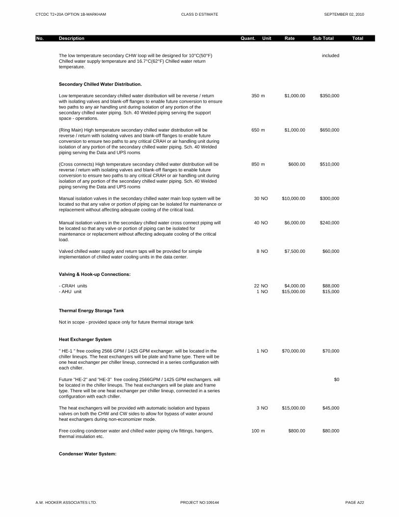
CTCDC T2+20A OPTION 1B-MARKHAM CLASS D ESTIMATE SEPTEMBER 02, 2010
No. Description Quant. Unit Rate Sub Total Total
The low temperature secondary CHW loop will be designed for 10°C(50°F) Chilled water supply temperature and 16.7°C(62°F) Chilled water return temperature.
included
Secondary Chilled Water Distribution.
Low temperature secondary chilled water distribution will be reverse / return with isolating valves and blank-off flanges to enable future conversion to ensure two paths to any air handling unit during isolation of any portion of the secondary chilled water piping. Sch. 40 Welded piping serving the support space - operations.
350 m $1,000.00 $350,000
(Ring Main) High temperature secondary chilled water distribution will be reverse / return with isolating valves and blank-off flanges to enable future conversion to ensure two paths to any critical CRAH or air handling unit during isolation of any portion of the secondary chilled water piping. Sch. 40 Welded piping serving the Data and UPS rooms
650 m $1,000.00 $650,000
(Cross connects) High temperature secondary chilled water distribution will be reverse / return with isolating valves and blank-off flanges to enable future conversion to ensure two paths to any critical CRAH or air handling unit during isolation of any portion of the secondary chilled water piping. Sch. 40 Welded piping serving the Data and UPS rooms
850 m $600.00 $510,000
Manual isolation valves in the secondary chilled water main loop system will be located so that any valve or portion of piping can be isolated for maintenance or replacement without affecting adequate cooling of the critical load.
30 NO $10,000.00 $300,000
Manual isolation valves in the secondary chilled water cross connect piping will be located so that any valve or portion of piping can be isolated for maintenance or replacement without affecting adequate cooling of the critical load.
40 NO $6,000.00 $240,000
Valved chilled water supply and return taps will be provided for simple implementation of chilled water cooling units in the data center.
8 NO $7,500.00 $60,000
Valving & Hook-up Connections:g p
- CRAH units 22 NO $4,000.00 $88,000- AHU unit 1 NO $15,000.00 $15,000
Thermal Energy Storage Tank
Not in scope - provided space only for future thermal storage tank
Heat Exchanger System
" HE-1 " free cooling 2566 GPM / 1425 GPM exchanger. will be located in the chiller lineups. The heat exchangers will be plate and frame type. There will be one heat exchanger per chiller lineup, connected in a series configuration with each chiller.
1 NO $70,000.00 $70,000
Future "HE-2" and "HE-3" free cooling 2566GPM / 1425 GPM exchangers. will be located in the chiller lineups. The heat exchangers will be plate and frame type. There will be one heat exchanger per chiller lineup, connected in a series configuration with each chiller.
$0
The heat exchangers will be provided with automatic isolation and bypass valves on both the CHW and CW sides to allow for bypass of water around heat exchangers during non-economizer mode.
3 NO $15,000.00 $45,000
Free cooling condenser water and chilled water piping c/w fittings, hangers, thermal insulation etc.
100 m $800.00 $80,000
Condenser Water System:
A.W. HOOKER ASSOCIATES LTD. PROJECT NO:109144 PAGE A22

CTCDC T2+20A OPTION 1B-MARKHAM CLASS D ESTIMATE SEPTEMBER 02, 2010
No. Description Quant. Unit Rate Sub Total Total
" CT-1 to CT-4" -1500 GPM,50 HP, each closed circuit fluid cooler will be sized to match the corresponding chiller, single cell units at 475 Tons each. The towers will be designed to withstand a 137 mph wind force. The towers will be FM Global certified c/w cooler fans with VFD's, sump heater, float level controls and variable frequency drives.
4 NO $200,000.00 $800,000
Future " CT-5 " and "CT-13 " - 1500 GPM. 50Hp each induced draft cooling towers will be sized to match the corresponding chiller, single cell units at 475 tons each. The towers will be designed to withstand a 137 mph wind force. The towers will be FM Global certified c/w sump heater, float level controls and variable frequency drives.
$0
"CTC-1 to CTC-4 " Cooling tower cleaning pump and distribution system 4 NO $8,000.00 $32,000
The cross flow cooling towers will be constructed of galvanized steel construction with stainless steel basins.
included
Note: The towers will be located on steel structure on grade. The towers will be elevated to allow for bottom connections of piping maintenance. There will be no automatic valves located outdoors. There will be grated walkways with handrails around the installed towers for maintenance. Walkways with hand rails will be integral to the tower around the fan shroud. with ships ladder access. included elsewhere in this estimate.
By. G.C
Exterior mains from the cooling towers to the heat exchangers w/o thermal insulation.
100 m $1,300.00 $130,000
Interior mains from the cooling towers to the heat exchangers c/w thermal insulation .
200 m $1,500.00 $300,000
Mains from the heat exchangers to the chillers c/w thermal insulation / Aluminum jacket .
50 m $1,500.00 $75,000
Variable volume condenser water pumps, one for each cooler and a redundant pump will be installed in the chiller room.
3 NO $35,000.00 $105,000
An indoor below ground water storage sump will be provided for each chiller system. The sumps will be located in the chiller plant. These sumps would be provided for a secondary cooling tower make-up water source. The sumps shall be two(2) nos. 56780 liters (summer peak) capacity. The sumps will be below
$0
( ) ( p ) p y pground in a sealed concrete pit. Sumps will need to be sized to capture all drained fluid during a line up shut down event. Sumps included elsewhere in this estimate by G.C
The exterior piping will be supported by the cooling tower support steel network. $0
Chemical Treatment & Circulation Filtration
- Condenser water filtration and treatment system equal to "Dolphin" 2 NO $40,000.00 $80,000- Chilled water chemical treatment (pot and bypass feeder and filter) 1 NO $5,000.00 $5,000- Glycol feed system c/w automated pump and initial glycol fill 1 NO $50,000.00 $50,000- Flushing and cleaning 1 NO $5,000.00 $5,000
Valving & Hook-up Connections:
- Closed circuit fluid coolers 2 NO $20,000.00 $40,000- Chillers - condenser side 2 NO $20,000.00 $40,000
- Chillers - evaporator side 2 NO $20,000.00 $40,000- Primary chilled water pumps 2 NO $15,000.00 $30,000- Secondary chilled water pumps 3 NO $15,000.00 $45,000- Condenser water pumps 3 NO $15,000.00 $45,000- Heat exchangers chiller and condenser side. 1 NO $40,000.00 $40,000
C1.33 - Steam and Condensate $0
No work required
C1.34 - Air Distribution $1,777,700
Computer Room Air Handling Units (CRAH’s)
A.W. HOOKER ASSOCIATES LTD. PROJECT NO:109144 PAGE A23
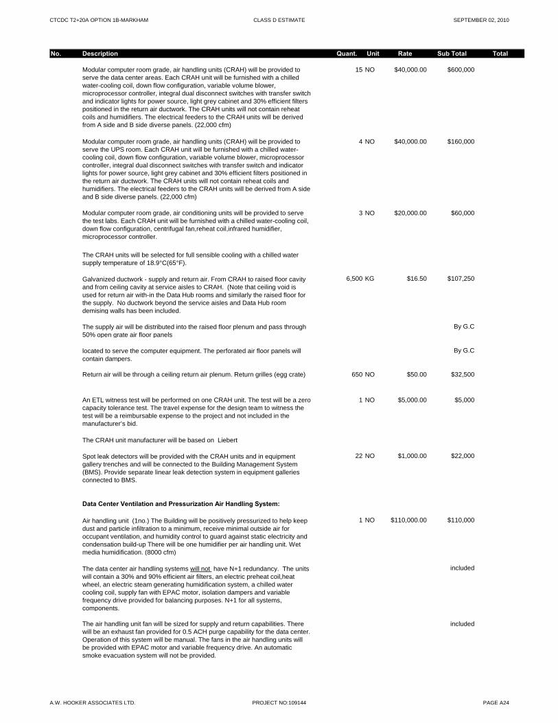
CTCDC T2+20A OPTION 1B-MARKHAM CLASS D ESTIMATE SEPTEMBER 02, 2010
No. Description Quant. Unit Rate Sub Total Total
Modular computer room grade, air handling units (CRAH) will be provided to serve the data center areas. Each CRAH unit will be furnished with a chilled water-cooling coil, down flow configuration, variable volume blower, microprocessor controller, integral dual disconnect switches with transfer switch and indicator lights for power source, light grey cabinet and 30% efficient filters positioned in the return air ductwork. The CRAH units will not contain reheat coils and humidifiers. The electrical feeders to the CRAH units will be derived from A side and B side diverse panels. (22,000 cfm)
15 NO $40,000.00 $600,000
Modular computer room grade, air handling units (CRAH) will be provided to serve the UPS room. Each CRAH unit will be furnished with a chilled water-cooling coil, down flow configuration, variable volume blower, microprocessor controller, integral dual disconnect switches with transfer switch and indicator lights for power source, light grey cabinet and 30% efficient filters positioned in the return air ductwork. The CRAH units will not contain reheat coils and humidifiers. The electrical feeders to the CRAH units will be derived from A side and B side diverse panels. (22,000 cfm)
4 NO $40,000.00 $160,000
Modular computer room grade, air conditioning units will be provided to serve the test labs. Each CRAH unit will be furnished with a chilled water-cooling coil, down flow configuration, centrifugal fan,reheat coil,infrared humidifier, microprocessor controller.
3 NO $20,000.00 $60,000
The CRAH units will be selected for full sensible cooling with a chilled water supply temperature of 18.9°C(65°F).
Galvanized ductwork - supply and return air. From CRAH to raised floor cavity and from ceiling cavity at service aisles to CRAH. (Note that ceiling void is used for return air with-in the Data Hub rooms and similarly the raised floor for the supply. No ductwork beyond the service aisles and Data Hub room demising walls has been included.
6,500 KG $16.50 $107,250
The supply air will be distributed into the raised floor plenum and pass through 50% open grate air floor panels
By G.C
located to serve the computer equipment. The perforated air floor panels will contain dampers.
By G.C
Return air will be through a ceiling return air plenum. Return grilles (egg crate) 650 NO $50.00 $32,500
An ETL witness test will be performed on one CRAH unit. The test will be a zero capacity tolerance test. The travel expense for the design team to witness the test will be a reimbursable expense to the project and not included in the manufacturer’s bid.
1 NO $5,000.00 $5,000
The CRAH unit manufacturer will be based on Liebert
Spot leak detectors will be provided with the CRAH units and in equipment gallery trenches and will be connected to the Building Management System (BMS). Provide separate linear leak detection system in equipment galleries connected to BMS.
22 NO $1,000.00 $22,000
Data Center Ventilation and Pressurization Air Handling System:
Air handling unit (1no.) The Building will be positively pressurized to help keep dust and particle infiltration to a minimum, receive minimal outside air for occupant ventilation, and humidity control to guard against static electricity and condensation build-up There will be one humidifier per air handling unit. Wet media humidification. (8000 cfm)
1 NO $110,000.00 $110,000
The data center air handling systems will not have N+1 redundancy. The units will contain a 30% and 90% efficient air filters, an electric preheat coil,heat wheel, an electric steam generating humidification system, a chilled water cooling coil, supply fan with EPAC motor, isolation dampers and variable frequency drive provided for balancing purposes. N+1 for all systems, components.
included
The air handling unit fan will be sized for supply and return capabilities. There will be an exhaust fan provided for 0.5 ACH purge capability for the data center. Operation of this system will be manual. The fans in the air handling units will be provided with EPAC motor and variable frequency drive. An automatic smoke evacuation system will not be provided.
included
A.W. HOOKER ASSOCIATES LTD. PROJECT NO:109144 PAGE A24
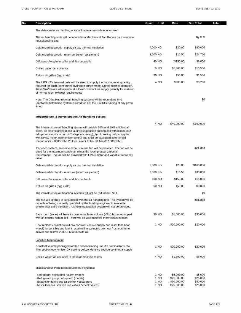
CTCDC T2+20A OPTION 1B-MARKHAM CLASS D ESTIMATE SEPTEMBER 02, 2010
No. Description Quant. Unit Rate Sub Total Total
The data center air handling units will have an air-side economizer.
The air handling units will be located in a Mechanical Fan Rooms on a concrete housekeeping pad.
By G.C
Galvanized ductwork - supply air c/w thermal insulation 4,000 KG $20.00 $80,000
Galvanized ductwork - return air (return air plenum) 1,500 KG $16.50 $24,750
Diffusers c/w spin-in collar and flex ductwork 40 NO $150.00 $6,000
Chilled water fan coil units 9 NO $1,500.00 $13,500
Return air grilles (egg crate) 30 NO $50.00 $1,500
The UPS VAV terminal units will be sized to supply the maximum air quantity required for each room during hydrogen purge mode. During normal operation, these VAV boxes will operate at a lower constant air supply quantity for makeup of normal room exhaust requirements
4 NO $800.00 $3,200
Note: The Data Hub room air handling systems will be redundant. N+1 (ductwork distribution system is sized for 1 of the 2 AHU's running at any given time.)
$0
Infrastructure & Administration Air Handling System:
The infrastructure air handling system will provide 30% and 90% efficient air filters, an electric preheat coil, a direct expansion cooling coil(with minimum 2 refrigerant circuits to permit 2 stage of cooling),glycol heating coil, supply fan with EPAC motor, economizer control and shall be packaged commercial rooftop units - 8000CFM( 20 tons) each( Total- 80 Tons(32,000CFM))
4 NO $40,000.00 $160,000
For each system, an in-line exhaust/return fan will be provided. The fan will be sized for the maximum supply air minus the room pressurization air requirement. The fan will be provided with EPAC motor and variable frequency drive.
included
Galvanized ductwork - supply air c/w thermal insulation 8,000 KG $20.00 $160,000
Galvanized ductwork - return air (return air plenum) 2,000 KG $16.50 $33,000
Diffusers c/w spin-in collar and flex ductwork 100 NO $150.00 $15,000
Return air grilles (egg crate) 60 NO $50.00 $3,000
The infrastructure air handling systems will not be redundant. N+1 $0
The fan will operate in conjunction with the air handling unit. The system will be capable of being manually operated by the building engineer to evacuate smoke after a fire condition. A smoke evacuation system will not be provided.
included
Each room (zone) will have its own variable air volume (VAV) boxes equipped with an electric reheat coil. There will be wall mounted thermostats in each
30 NO $1,000.00 $30,000
Heat reclaim ventilation unit c/w constant volume supply and relief fans,heat wheel( for sensible and latent reclaim),filters,electric pre-heat frost control-to deliver and relieve 2000CFM of outside air.
1 NO $20,000.00 $20,000
Facilities Management
Constant volume packaged rooftop airconditioning unit -15 nominal tons-c/w filter section,economizer,DX cooling coil,condensing section centrifugal supply
1 NO $20,000.00 $20,000
Chilled water fan coil units in elevator machine rooms 4 NO $1,500.00 $6,000
Miscellaneous Plant room equipment / systems:
- Refrigerant monitoring / alarm system 1 NO $5,000.00 $5,000- Refrigerant pump out system (mobile) 1 NO $25,000.00 $25,000- Expansion tanks and air control / separators 1 NO $50,000.00 $50,000- Miscellaneous isolation line valves / check valves 1 NO $25,000.00 $25,000
A.W. HOOKER ASSOCIATES LTD. PROJECT NO:109144 PAGE A25
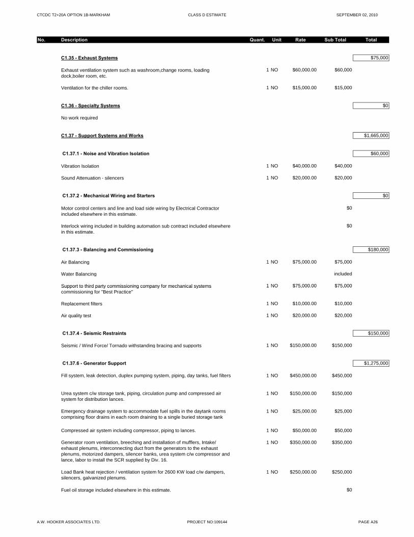
CTCDC T2+20A OPTION 1B-MARKHAM CLASS D ESTIMATE SEPTEMBER 02, 2010
No. Description Quant. Unit Rate Sub Total Total
C1.35 - Exhaust Systems $75,000
Exhaust ventilation system such as washroom,change rooms, loading dock,boiler room, etc.
1 NO $60,000.00 $60,000
Ventilation for the chiller rooms. 1 NO $15,000.00 $15,000
C1.36 - Specialty Systems $0
No work required
C1.37 - Support Systems and Works $1,665,000
C1.37.1 - Noise and Vibration Isolation $60,000
Vibration Isolation 1 NO $40,000.00 $40,000
Sound Attenuation - silencers 1 NO $20,000.00 $20,000
C1.37.2 - Mechanical Wiring and Starters $0
Motor control centers and line and load side wiring by Electrical Contractor included elsewhere in this estimate.
$0
Interlock wiring included in building automation sub contract included elsewhere in this estimate.
$0
C1.37.3 - Balancing and Commissioning $180,000
Air Balancing 1 NO $75,000.00 $75,000
Water Balancing included
Support to third party commissioning company for mechanical systems 1 NO $75,000.00 $75,000Support to third party commissioning company for mechanical systems commissioning for "Best Practice"
1 NO $75,000.00 $75,000
Replacement filters 1 NO $10,000.00 $10,000
Air quality test 1 NO $20,000.00 $20,000
C1.37.4 - Seismic Restraints $150,000
Seismic / Wind Force/ Tornado withstanding bracing and supports 1 NO $150,000.00 $150,000
C1.37.6 - Generator Support $1,275,000
Fill system, leak detection, duplex pumping system, piping, day tanks, fuel filters 1 NO $450,000.00 $450,000
Urea system c/w storage tank, piping, circulation pump and compressed air system for distribution lances.
1 NO $150,000.00 $150,000
Emergency drainage system to accommodate fuel spills in the daytank rooms comprising floor drains in each room draining to a single buried storage tank
1 NO $25,000.00 $25,000
Compressed air system including compressor, piping to lances. 1 NO $50,000.00 $50,000
Generator room ventilation, breeching and installation of mufflers, Intake/ exhaust plenums, interconnecting duct from the generators to the exhaust plenums, motorized dampers, silencer banks, urea system c/w compressor and lance, labor to install the SCR supplied by Div. 16.
1 NO $350,000.00 $350,000
Load Bank heat rejection / ventilation system for 2600 KW load c/w dampers, silencers, galvanized plenums.
1 NO $250,000.00 $250,000
Fuel oil storage included elsewhere in this estimate. $0
A.W. HOOKER ASSOCIATES LTD. PROJECT NO:109144 PAGE A26
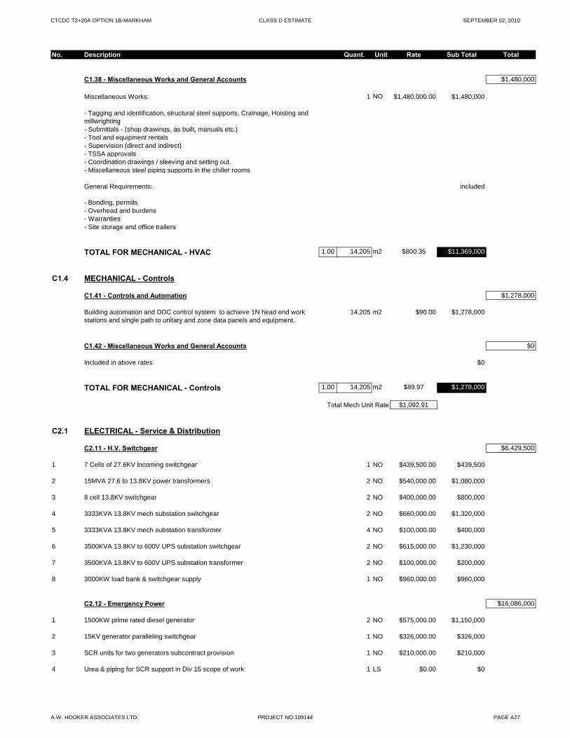
CTCDC T2+20A OPTION 1B-MARKHAM CLASS D ESTIMATE SEPTEMBER 02, 2010
No. Description Quant. Unit Rate Sub Total Total
C1.38 - Miscellaneous Works and General Accounts $1,480,000
Miscellaneous Works: 1 NO $1,480,000.00 $1,480,000
- Tagging and identification, structural steel supports, Crainage, Hoisting and millwrighting- Submittals - (shop drawings, as built, manuals etc.)- Tool and equipment rentals- Supervision (direct and indirect)- TSSA approvals- Coordination drawings / sleeving and setting out.- Miscellaneous steel piping supports in the chiller rooms
General Requirements: included
- Bonding, permits- Overhead and burdens- Warranties- Site storage and office trailers
TOTAL FOR MECHANICAL - HVAC 1.00 14,205 m2 $800.35 $11,369,000
C1.4 MECHANICAL - Controls
C1.41 - Controls and Automation $1,278,000
Building automation and DDC control system to achieve 1N head end work stations and single path to unitary and zone data panels and equipment.
14,205 m2 $90.00 $1,278,000
C1.42 - Miscellaneous Works and General Accounts $0
Included in above rates $0
TOTAL FOR MECHANICAL - Controls 1.00 14,205 m2 $89.97 $1,278,000
Total Mech Unit Rate $1,092.91
C2.1 ELECTRICAL - Service & Distribution
C2.11 - H.V. Switchgear $6,429,500
1 7 Cells of 27.6KV incoming switchgear 1 NO $439,500.00 $439,500
2 15MVA 27.6 to 13.8KV power transformers 2 NO $540,000.00 $1,080,000
3 8 cell 13.8KV switchgear 2 NO $400,000.00 $800,000
4 3333KVA 13.8KV mech substation switchgear 2 NO $660,000.00 $1,320,000
5 3333KVA 13.8KV mech substation transformer 4 NO $100,000.00 $400,000
6 3500KVA 13.8KV to 600V UPS substation switchgear 2 NO $615,000.00 $1,230,000
7 3500KVA 13.8KV to 600V UPS substation transformer 2 NO $100,000.00 $200,000
8 3000KW load bank & switchgear supply 1 NO $960,000.00 $960,000
C2.12 - Emergency Power $16,086,000
1 1500KW prime rated diesel generator 2 NO $575,000.00 $1,150,000
2 15KV generator paralleling switchgear 1 NO $326,000.00 $326,000
3 SCR units for two generators subcontract provision 1 NO $210,000.00 $210,000
4 Urea & piping for SCR support in Div 15 scope of work 1 LS $0.00 $0
A.W. HOOKER ASSOCIATES LTD. PROJECT NO:109144 PAGE A27
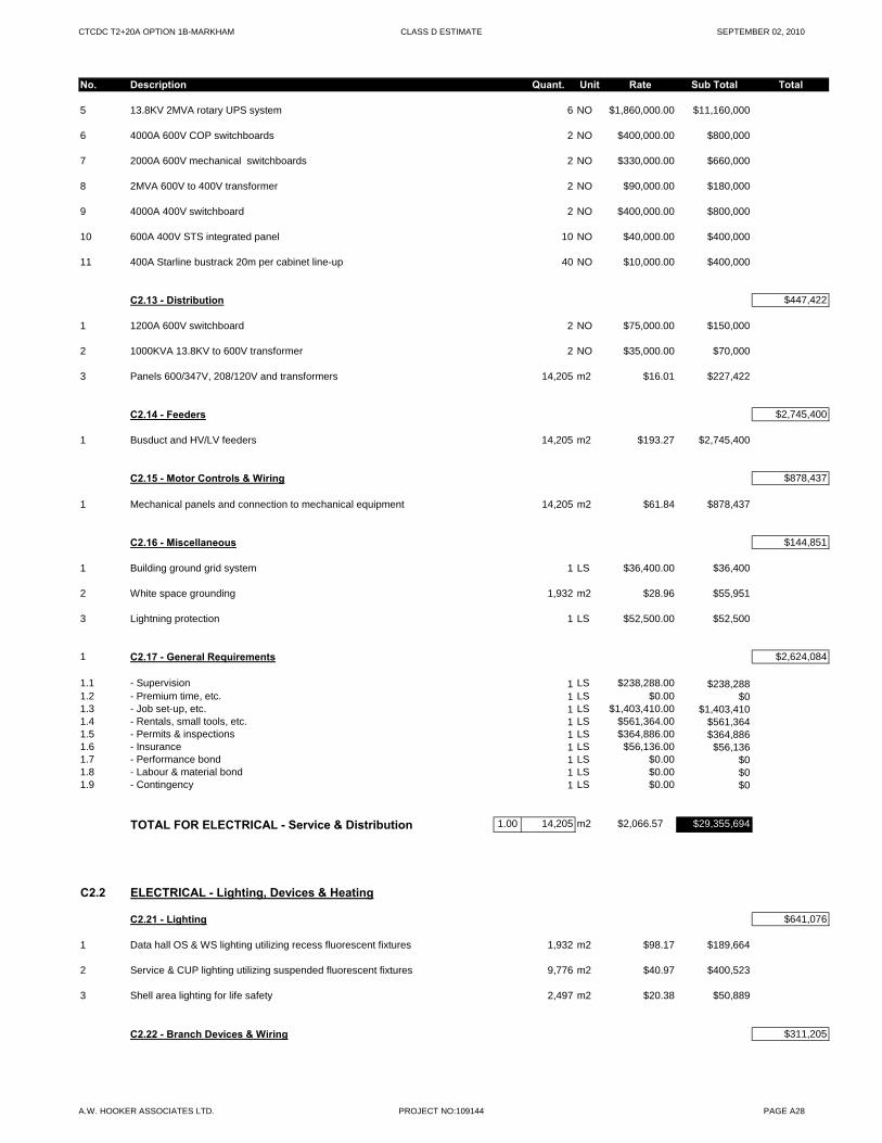
CTCDC T2+20A OPTION 1B-MARKHAM CLASS D ESTIMATE SEPTEMBER 02, 2010
No. Description Quant. Unit Rate Sub Total Total
5 13.8KV 2MVA rotary UPS system 6 NO $1,860,000.00 $11,160,000
6 4000A 600V COP switchboards 2 NO $400,000.00 $800,000
7 2000A 600V mechanical switchboards 2 NO $330,000.00 $660,000
8 2MVA 600V to 400V transformer 2 NO $90,000.00 $180,000
9 4000A 400V switchboard 2 NO $400,000.00 $800,000
10 600A 400V STS integrated panel 10 NO $40,000.00 $400,000
11 400A Starline bustrack 20m per cabinet line-up 40 NO $10,000.00 $400,000
C2.13 - Distribution $447,422
1 1200A 600V switchboard 2 NO $75,000.00 $150,000
2 1000KVA 13.8KV to 600V transformer 2 NO $35,000.00 $70,000
3 Panels 600/347V, 208/120V and transformers 14,205 m2 $16.01 $227,422
C2.14 - Feeders $2,745,400
1 Busduct and HV/LV feeders 14,205 m2 $193.27 $2,745,400
C2.15 - Motor Controls & Wiring $878,437
1 Mechanical panels and connection to mechanical equipment 14,205 m2 $61.84 $878,437
C2.16 - Miscellaneous $144,851
1 Building ground grid system 1 LS $36,400.00 $36,400
2 White space grounding 1,932 m2 $28.96 $55,951
3 Lightning protection 1 LS $52,500.00 $52,500
1 C2.17 - General Requirements $2,624,084
1.1 - Supervision 1 LS $238,288.00 $238,2881.2 - Premium time, etc. 1 LS $0.00 $01.3 - Job set-up, etc. 1 LS $1,403,410.00 $1,403,4101.4 - Rentals, small tools, etc. 1 LS $561,364.00 $561,3641.5 - Permits & inspections 1 LS $364,886.00 $364,8861.6 - Insurance 1 LS $56,136.00 $56,1361.7 - Performance bond 1 LS $0.00 $01.8 - Labour & material bond 1 LS $0.00 $01.9 - Contingency 1 LS $0.00 $0
TOTAL FOR ELECTRICAL - Service & Distribution 1.00 14,205 m2 $2,066.57 $29,355,694
C2.2 ELECTRICAL - Lighting, Devices & Heating
C2.21 - Lighting $641,076
1 Data hall OS & WS lighting utilizing recess fluorescent fixtures 1,932 m2 $98.17 $189,664
2 Service & CUP lighting utilizing suspended fluorescent fixtures 9,776 m2 $40.97 $400,523
3 Shell area lighting for life safety 2,497 m2 $20.38 $50,889
C2.22 - Branch Devices & Wiring $311,205
A.W. HOOKER ASSOCIATES LTD. PROJECT NO:109144 PAGE A28
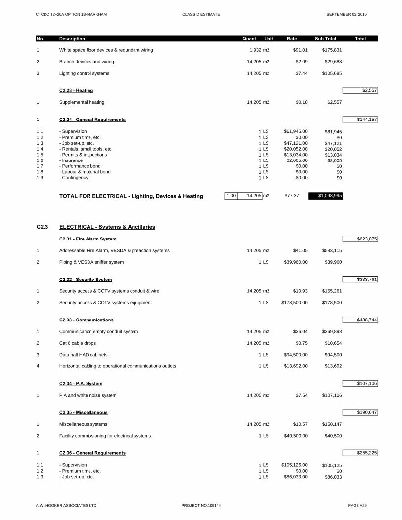
CTCDC T2+20A OPTION 1B-MARKHAM CLASS D ESTIMATE SEPTEMBER 02, 2010
No. Description Quant. Unit Rate Sub Total Total
1 White space floor devices & redundant wiring 1,932 m2 $91.01 $175,831
2 Branch devices and wiring 14,205 m2 $2.09 $29,688
3 Lighting control systems 14,205 m2 $7.44 $105,685
C2.23 - Heating $2,557
1 Supplemental heating 14,205 m2 $0.18 $2,557
1 C2.24 - General Requirements $144,157
1.1 - Supervision 1 LS $61,945.00 $61,9451.2 - Premium time, etc. 1 LS $0.00 $01.3 - Job set-up, etc. 1 LS $47,121.00 $47,1211.4 - Rentals, small tools, etc. 1 LS $20,052.00 $20,0521.5 - Permits & inspections 1 LS $13,034.00 $13,0341.6 - Insurance 1 LS $2,005.00 $2,0051.7 - Performance bond 1 LS $0.00 $01.8 - Labour & material bond 1 LS $0.00 $01.9 - Contingency 1 LS $0.00 $0
TOTAL FOR ELECTRICAL - Lighting, Devices & Heating 1.00 14,205 m2 $77.37 $1,098,995
C2.3 ELECTRICAL - Systems & Ancillaries
C2.31 - Fire Alarm System $623,075
1 Addressable Fire Alarm, VESDA & preaction systems 14,205 m2 $41.05 $583,115
2 Piping & VESDA sniffer system 1 LS $39,960.00 $39,960
C2 32 Security System $333 761C2.32 - Security System $333,761
1 Security access & CCTV systems conduit & wire 14,205 m2 $10.93 $155,261
2 Security access & CCTV systems equipment 1 LS $178,500.00 $178,500
C2.33 - Communications $488,744
1 Communication empty conduit system 14,205 m2 $26.04 $369,898
2 Cat 6 cable drops 14,205 m2 $0.75 $10,654
3 Data hall HAD cabinets 1 LS $94,500.00 $94,500
4 Horizontal cabling to operational communications outlets 1 LS $13,692.00 $13,692
C2.34 - P.A. System $107,106
1 P A and white noise system 14,205 m2 $7.54 $107,106
C2.35 - Miscellaneous $190,647
1 Miscellaneous systems 14,205 m2 $10.57 $150,147
2 Facility commissioning for electrical systems 1 LS $40,500.00 $40,500
1 C2.36 - General Requirements $255,225
1.1 - Supervision 1 LS $105,125.00 $105,1251.2 - Premium time, etc. 1 LS $0.00 $01.3 - Job set-up, etc. 1 LS $86,033.00 $86,033
A.W. HOOKER ASSOCIATES LTD. PROJECT NO:109144 PAGE A29
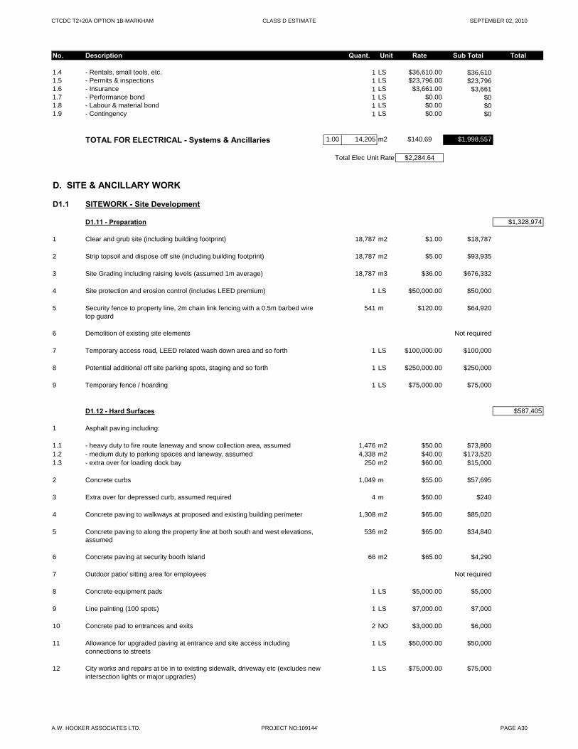
CTCDC T2+20A OPTION 1B-MARKHAM CLASS D ESTIMATE SEPTEMBER 02, 2010
No. Description Quant. Unit Rate Sub Total Total
1.4 - Rentals, small tools, etc. 1 LS $36,610.00 $36,6101.5 - Permits & inspections 1 LS $23,796.00 $23,7961.6 - Insurance 1 LS $3,661.00 $3,6611.7 - Performance bond 1 LS $0.00 $01.8 - Labour & material bond 1 LS $0.00 $01.9 - Contingency 1 LS $0.00 $0
TOTAL FOR ELECTRICAL - Systems & Ancillaries 1.00 14,205 m2 $140.69 $1,998,557
Total Elec Unit Rate $2,284.64
D. SITE & ANCILLARY WORK
D1.1 SITEWORK - Site Development
D1.11 - Preparation $1,328,974
1 Clear and grub site (including building footprint) 18,787 m2 $1.00 $18,787
2 Strip topsoil and dispose off site (including building footprint) 18,787 m2 $5.00 $93,935
3 Site Grading including raising levels (assumed 1m average) 18,787 m3 $36.00 $676,332
4 Site protection and erosion control (includes LEED premium) 1 LS $50,000.00 $50,000
5 Security fence to property line, 2m chain link fencing with a 0.5m barbed wire top guard
541 m $120.00 $64,920
6 Demolition of existing site elements Not required
7 Temporary access road, LEED related wash down area and so forth 1 LS $100,000.00 $100,000
8 Potential additional off site parking spots, staging and so forth 1 LS $250,000.00 $250,000
9 Temporary fence / hoarding 1 LS $75,000.00 $75,000
D1.12 - Hard Surfaces $587,405
1 Asphalt paving including:
1.1 - heavy duty to fire route laneway and snow collection area, assumed 1,476 m2 $50.00 $73,8001.2 - medium duty to parking spaces and laneway, assumed 4,338 m2 $40.00 $173,5201.3 - extra over for loading dock bay 250 m2 $60.00 $15,000
2 Concrete curbs 1,049 m $55.00 $57,695
3 Extra over for depressed curb, assumed required 4 m $60.00 $240
4 Concrete paving to walkways at proposed and existing building perimeter 1,308 m2 $65.00 $85,020
5 Concrete paving to along the property line at both south and west elevations, assumed
536 m2 $65.00 $34,840
6 Concrete paving at security booth Island 66 m2 $65.00 $4,290
7 Outdoor patio/ sitting area for employees Not required
8 Concrete equipment pads 1 LS $5,000.00 $5,000
9 Line painting (100 spots) 1 LS $7,000.00 $7,000
10 Concrete pad to entrances and exits 2 NO $3,000.00 $6,000
11 Allowance for upgraded paving at entrance and site access including connections to streets
1 LS $50,000.00 $50,000
12 City works and repairs at tie in to existing sidewalk, driveway etc (excludes new intersection lights or major upgrades)
1 LS $75,000.00 $75,000
A.W. HOOKER ASSOCIATES LTD. PROJECT NO:109144 PAGE A30
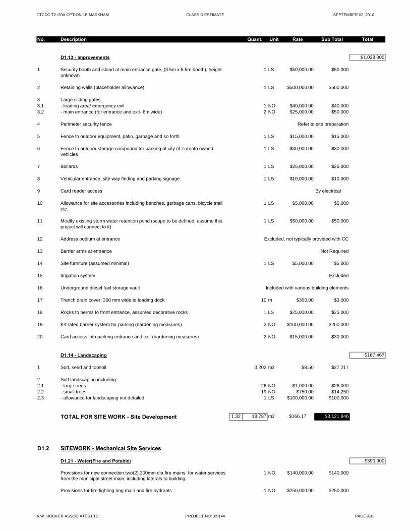
CTCDC T2+20A OPTION 1B-MARKHAM CLASS D ESTIMATE SEPTEMBER 02, 2010
No. Description Quant. Unit Rate Sub Total Total
D1.13 - Improvements $1,038,000
1 Security booth and island at main entrance gate, (3.5m x 5.5m booth), height unknown
1 LS $50,000.00 $50,000
2 Retaining walls (placeholder allowance) 1 LS $500,000.00 $500,000
3 Large sliding gates3.1 - loading area/ emergency exit 1 NO $40,000.00 $40,0003.2 - main entrance (for entrance and exit- 6m wide) 2 NO $25,000.00 $50,000
4 Perimeter security fence Refer to site preparation
5 Fence to outdoor equipment, patio, garbage and so forth 1 LS $15,000.00 $15,000
6 Fence to outdoor storage compound for parking of city of Toronto owned vehicles
1 LS $30,000.00 $30,000
7 Bollards 1 LS $25,000.00 $25,000
8 Vehicular entrance, site way finding and parking signage 1 LS $10,000.00 $10,000
9 Card reader access By electrical
10 Allowance for site accessories including benches, garbage cans, bicycle stall etc.
1 LS $5,000.00 $5,000
11 Modify existing storm water retention pond (scope to be defined, assume this project will connect to it)
1 LS $50,000.00 $50,000
12 Address podium at entrance Excluded, not typically provided with CC
13 Barrier arms at entrance Not Required
14 Site furniture (assumed minimal) 1 LS $5,000.00 $5,000
15 Irrigation system Excluded
16 Underground diesel fuel storage vault Included with various building elements
17 Trench drain cover, 300 mm wide to loading dock 10 m $300.00 $3,000
18 Rocks to berms to front entrance, assumed decorative rocks 1 LS $25,000.00 $25,000
19 K4 rated barrier system for parking (hardening measures) 2 NO $100,000.00 $200,000
20 Card access into parking entrance and exit (hardening measures) 2 NO $15,000.00 $30,000
D1.14 - Landscaping $167,467
1 Sod, seed and topsoil 3,202 m2 $8.50 $27,217
2 Soft landscaping including:2.1 - large trees 26 NO $1,000.00 $26,0002.2 - small trees 19 NO $750.00 $14,2502.3 - allowance for landscaping not detailed 1 LS $100,000.00 $100,000
TOTAL FOR SITE WORK - Site Development 1.32 18,787 m2 $166.17 $3,121,846
D1.2 SITEWORK - Mechanical Site Services
D1.21 - Water(Fire and Potable) $390,000
Provisions for new connection two(2) 200mm dia.fire mains for water services from the municipal street main, including laterals to building.
1 NO $140,000.00 $140,000
Provisions for fire fighting ring main and fire hydrants 1 NO $250,000.00 $250,000
A.W. HOOKER ASSOCIATES LTD. PROJECT NO:109144 PAGE A31
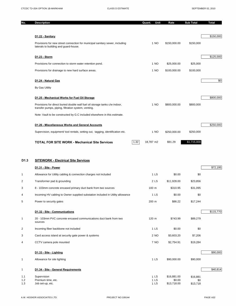
CTCDC T2+20A OPTION 1B-MARKHAM CLASS D ESTIMATE SEPTEMBER 02, 2010
No. Description Quant. Unit Rate Sub Total Total
D1.22 - Sanitary $150,000
Provisions for new street connection for municipal sanitary sewer, including laterals to building and guard-house.
1 NO $150,000.00 $150,000
D1.23 - Storm $125,000
Provisions for connection to storm water retention pond. 1 NO $25,000.00 $25,000
Provisions for drainage to new hard surface areas. 1 NO $100,000.00 $100,000
D1.24 - Natural Gas $0
By Gas Utility
D1.25 - Mechanical Works for Fuel Oil Storage $800,000
Provisions for direct buried double wall fuel oil storage tanks c/w indoor, transfer pumps, piping, filtration system, venting.
1 NO $800,000.00 $800,000
Note: Vault to be constructed by G.C included elsewhere in this estimate.
D1.26 - Miscellaneous Works and General Accounts $250,000
Supervision, equipment/ tool rentals, setting out, tagging, identification etc. 1 NO $250,000.00 $250,000
TOTAL FOR SITE WORK - Mechanical Site Services 1.32 18,787 m2 $91.29 $1,715,000
D1.3 SITEWORK - Electrical Site Services
D1.31 - Site - Power $72,195
1 Allowance for Utility cabling & connection charges not included 1 LS $0.00 $0
2 Transformer pad & grounding 2 LS $11,928.00 $23,856
3 8 - 103mm concrete encased primary duct bank from two sources 100 m $310.95 $31,095
4 Incoming HV cabling to Owner supplied substation included in Utility allowance 1 LS $0.00 $0
5 Power to security gates 200 m $86.22 $17,244
D1.32 - Site - Communications $115,770
1 20 - 103mm PVC concrete encased communications duct bank from two sources
120 m $743.99 $89,279
2 Incoming fiber backbone not included 1 LS $0.00 $0
3 Card access island at security gate power & systems 2 NO $3,603.20 $7,206
4 CCTV camera pole mounted 7 NO $2,754.91 $19,284
D1.33 - Site - Lighting $90,000
1 Allowance for site lighting 1 LS $90,000.00 $90,000
1 D1.34 - Site - General Requirements $40,814
1.1 Supervision 1 LS $16,881.00 $16,8811.2 Premium time, etc. 1 LS $0.00 $01.3 Job set-up, etc. 1 LS $13,718.00 $13,718
A.W. HOOKER ASSOCIATES LTD. PROJECT NO:109144 PAGE A32
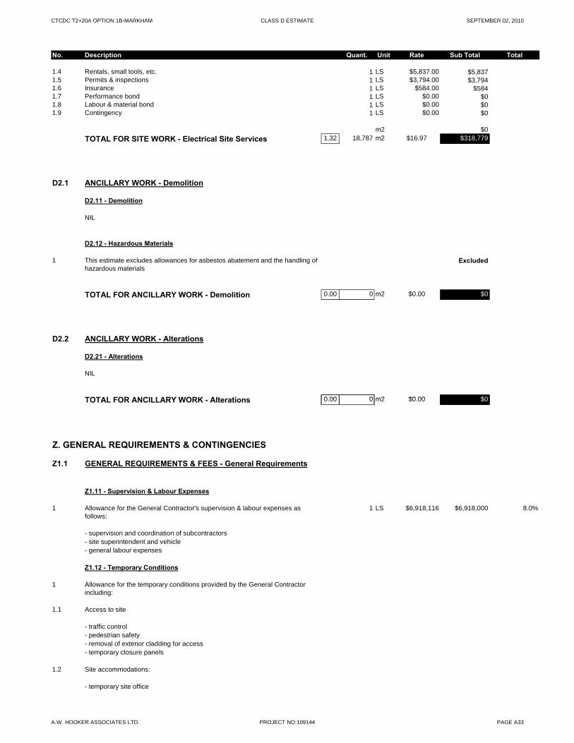
CTCDC T2+20A OPTION 1B-MARKHAM CLASS D ESTIMATE SEPTEMBER 02, 2010
No. Description Quant. Unit Rate Sub Total Total
1.4 Rentals, small tools, etc. 1 LS $5,837.00 $5,8371.5 Permits & inspections 1 LS $3,794.00 $3,7941.6 Insurance 1 LS $584.00 $5841.7 Performance bond 1 LS $0.00 $01.8 Labour & material bond 1 LS $0.00 $01.9 Contingency 1 LS $0.00 $0
m2 $0
TOTAL FOR SITE WORK - Electrical Site Services 1.32 18,787 m2 $16.97 $318,779
D2.1 ANCILLARY WORK - Demolition
D2.11 - Demolition
NIL
D2.12 - Hazardous Materials
1 This estimate excludes allowances for asbestos abatement and the handling of hazardous materials
Excluded
TOTAL FOR ANCILLARY WORK - Demolition 0.00 0 m2 $0.00 $0
D2.2 ANCILLARY WORK - Alterations
D2.21 - Alterations
NIL
TOTAL FOR ANCILLARY WORK Alt ti 0 00 0 m2 $0 00 $0TOTAL FOR ANCILLARY WORK - Alterations 0.00 0 m2 $0.00 $0
Z. GENERAL REQUIREMENTS & CONTINGENCIES
Z1.1 GENERAL REQUIREMENTS & FEES - General Requirements
Z1.11 - Supervision & Labour Expenses
1 Allowance for the General Contractor's supervision & labour expenses as follows:
1 LS $6,918,116 $6,918,000 8.0%
- supervision and coordination of subcontractors- site superintendent and vehicle- general labour expenses
Z1.12 - Temporary Conditions
1 Allowance for the temporary conditions provided by the General Contractor including:
1.1 Access to site
- traffic control- pedestrian safety- removal of exterior cladding for access- temporary closure panels
1.2 Site accommodations:
- temporary site office
A.W. HOOKER ASSOCIATES LTD. PROJECT NO:109144 PAGE A33
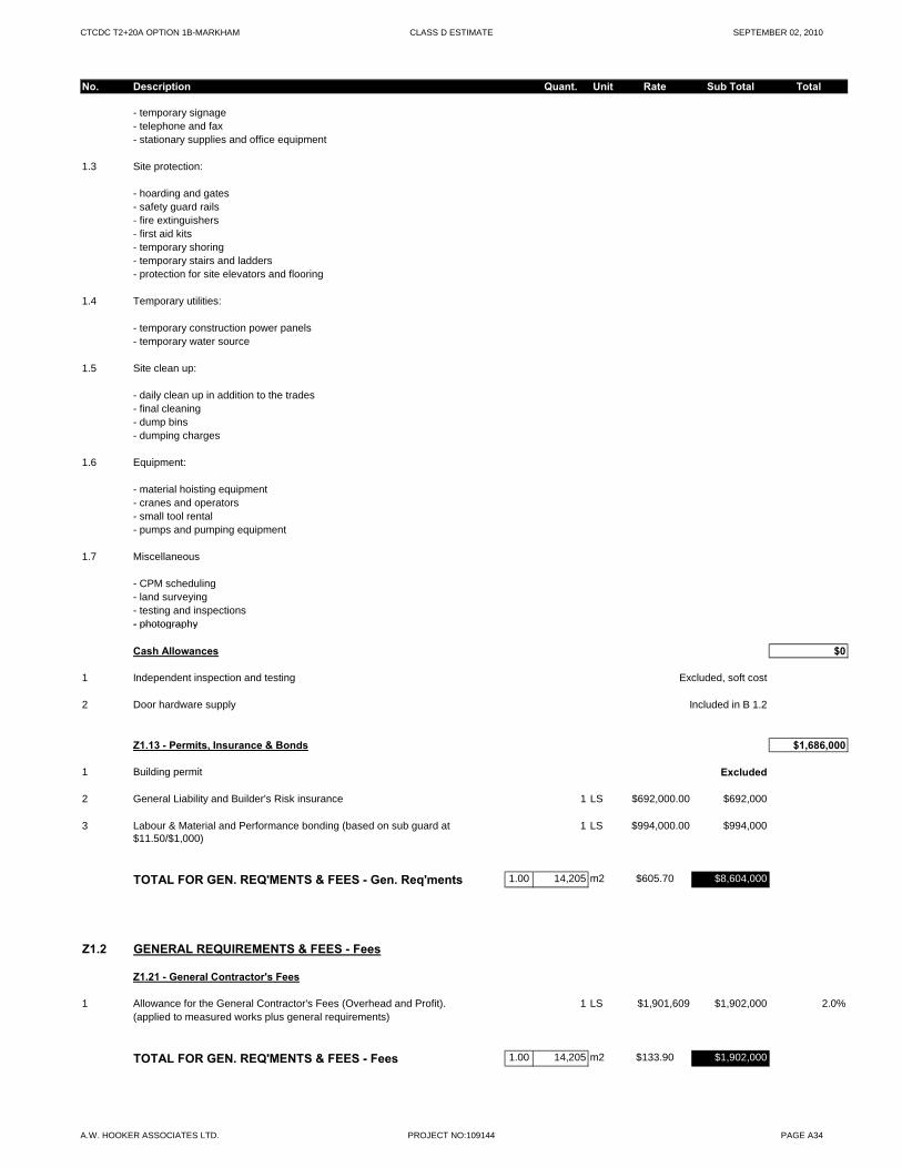
CTCDC T2+20A OPTION 1B-MARKHAM CLASS D ESTIMATE SEPTEMBER 02, 2010
No. Description Quant. Unit Rate Sub Total Total
- temporary signage- telephone and fax- stationary supplies and office equipment
1.3 Site protection:
- hoarding and gates- safety guard rails- fire extinguishers- first aid kits- temporary shoring- temporary stairs and ladders- protection for site elevators and flooring
1.4 Temporary utilities:
- temporary construction power panels- temporary water source
1.5 Site clean up:
- daily clean up in addition to the trades- final cleaning- dump bins- dumping charges
1.6 Equipment:
- material hoisting equipment - cranes and operators- small tool rental- pumps and pumping equipment
1.7 Miscellaneous
- CPM scheduling- land surveying- testing and inspections- photography- photography
Cash Allowances $0
1 Independent inspection and testing Excluded, soft cost
2 Door hardware supply Included in B 1.2
Z1.13 - Permits, Insurance & Bonds $1,686,000
1 Building permit Excluded
2 General Liability and Builder's Risk insurance 1 LS $692,000.00 $692,000
3 Labour & Material and Performance bonding (based on sub guard at $11.50/$1,000)
1 LS $994,000.00 $994,000
TOTAL FOR GEN. REQ'MENTS & FEES - Gen. Req'ments 1.00 14,205 m2 $605.70 $8,604,000
Z1.2 GENERAL REQUIREMENTS & FEES - Fees
Z1.21 - General Contractor's Fees
1 Allowance for the General Contractor's Fees (Overhead and Profit). 1 LS $1,901,609 $1,902,000 2.0%(applied to measured works plus general requirements)
TOTAL FOR GEN. REQ'MENTS & FEES - Fees 1.00 14,205 m2 $133.90 $1,902,000
A.W. HOOKER ASSOCIATES LTD. PROJECT NO:109144 PAGE A34
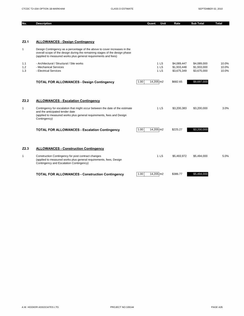
CTCDC T2+20A OPTION 1B-MARKHAM CLASS D ESTIMATE SEPTEMBER 02, 2010
No. Description Quant. Unit Rate Sub Total Total
Z2.1 ALLOWANCES - Design Contingency
1 Design Contingency as a percentage of the above to cover increases in the overall scope of the design during the remaining stages of the design phase(applied to measured works plus general requirements and fees)
1.1 - Architectural / Structural / Site works 1 LS $4,089,447 $4,089,000 10.0%1.2 - Mechanical Services 1 LS $1,933,448 $1,933,000 10.0%1.3 - Electrical Services 1 LS $3,675,349 $3,675,000 10.0%
TOTAL FOR ALLOWANCES - Design Contingency 1.00 14,205 m2 $682.65 $9,697,000
Z2.2 ALLOWANCES - Escalation Contingency
1 Contingency for escalation that might occur between the date of the estimate and the anticipated tender date
1 LS $3,200,383 $3,200,000 3.0%
(applied to measured works plus general requirements, fees and Design Contingency)
TOTAL FOR ALLOWANCES - Escalation Contingency 1.00 14,205 m2 $225.27 $3,200,000
Z2.3 ALLOWANCES - Construction Contingency
1 Construction Contingency for post contract changes 1 LS $5,493,972 $5,494,000 5.0%(applied to measured works plus general requirements, fees, Design Contingency and Escalation Contingency)
TOTAL FOR ALLOWANCES - Construction Contingency 1.00 14,205 m2 $386.77 $5,494,000
A.W. HOOKER ASSOCIATES LTD. PROJECT NO:109144 PAGE A35

SECTION F CONCLUSIONS
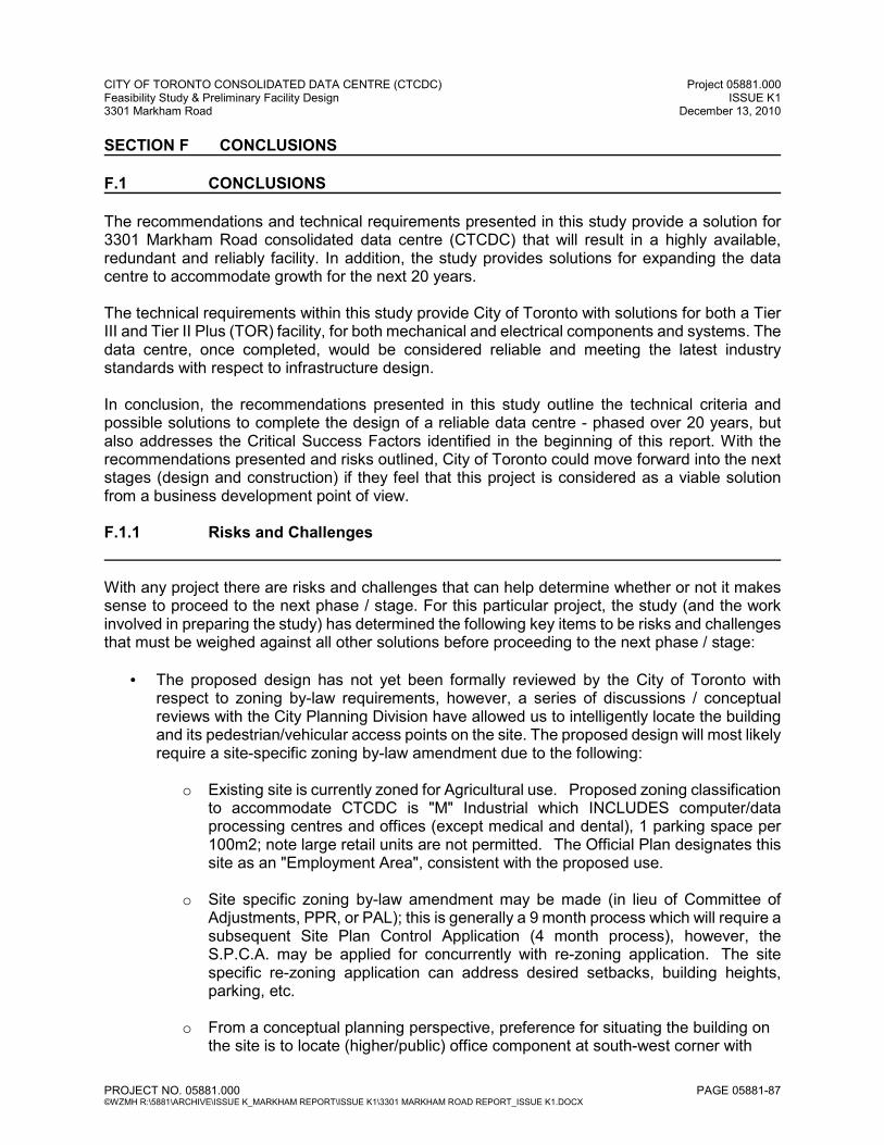
CITY OF TORONTO CONSOLIDATED DATA CENTRE (CTCDC) Project 05881.000 Feasibility Study & Preliminary Facility Design ISSUE K1 3301 Markham Road December 13, 2010
PROJECT NO. 05881.000 PAGE 05881-87 ©WZMH R:\5881\ARCHIVE\ISSUE K_MARKHAM REPORT\ISSUE K1\3301 MARKHAM ROAD REPORT_ISSUE K1.DOCX
SECTION F CONCLUSIONS F.1 CONCLUSIONS The recommendations and technical requirements presented in this study provide a solution for 3301 Markham Road consolidated data centre (CTCDC) that will result in a highly available, redundant and reliably facility. In addition, the study provides solutions for expanding the data centre to accommodate growth for the next 20 years. The technical requirements within this study provide City of Toronto with solutions for both a Tier III and Tier II Plus (TOR) facility, for both mechanical and electrical components and systems. The data centre, once completed, would be considered reliable and meeting the latest industry standards with respect to infrastructure design. In conclusion, the recommendations presented in this study outline the technical criteria and possible solutions to complete the design of a reliable data centre - phased over 20 years, but also addresses the Critical Success Factors identified in the beginning of this report. With the recommendations presented and risks outlined, City of Toronto could move forward into the next stages (design and construction) if they feel that this project is considered as a viable solution from a business development point of view. F.1.1 Risks and Challenges With any project there are risks and challenges that can help determine whether or not it makes sense to proceed to the next phase / stage. For this particular project, the study (and the work involved in preparing the study) has determined the following key items to be risks and challenges that must be weighed against all other solutions before proceeding to the next phase / stage:
• The proposed design has not yet been formally reviewed by the City of Toronto with respect to zoning by-law requirements, however, a series of discussions / conceptual reviews with the City Planning Division have allowed us to intelligently locate the building and its pedestrian/vehicular access points on the site. The proposed design will most likely require a site-specific zoning by-law amendment due to the following:
o Existing site is currently zoned for Agricultural use. Proposed zoning classification
to accommodate CTCDC is "M" Industrial which INCLUDES computer/data processing centres and offices (except medical and dental), 1 parking space per 100m2; note large retail units are not permitted. The Official Plan designates this site as an "Employment Area", consistent with the proposed use.
o Site specific zoning by-law amendment may be made (in lieu of Committee of
Adjustments, PPR, or PAL); this is generally a 9 month process which will require a subsequent Site Plan Control Application (4 month process), however, the S.P.C.A. may be applied for concurrently with re-zoning application. The site specific re-zoning application can address desired setbacks, building heights, parking, etc.
o From a conceptual planning perspective, preference for situating the building on
the site is to locate (higher/public) office component at south-west corner with
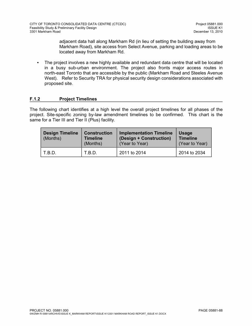
CITY OF TORONTO CONSOLIDATED DATA CENTRE (CTCDC) Project 05881.000 Feasibility Study & Preliminary Facility Design ISSUE K1 3301 Markham Road December 13, 2010
PROJECT NO. 05881.000 PAGE 05881-88 ©WZMH R:\5881\ARCHIVE\ISSUE K_MARKHAM REPORT\ISSUE K1\3301 MARKHAM ROAD REPORT_ISSUE K1.DOCX
adjacent data hall along Markham Rd (in lieu of setting the building away from Markham Road), site access from Select Avenue, parking and loading areas to be located away from Markham Rd.
• The project involves a new highly available and redundant data centre that will be located
in a busy sub-urban environment. The project also fronts major access routes in north-east Toronto that are accessible by the public (Markham Road and Steeles Avenue West). Refer to Security TRA for physical security design considerations associated with proposed site.
F.1.2 Project Timelines The following chart identifies at a high level the overall project timelines for all phases of the project. Site-specific zoning by-law amendment timelines to be confirmed. This chart is the same for a Tier III and Tier II (Plus) facility.
Design Timeline (Months)
Construction Timeline (Months)
Implementation Timeline (Design + Construction) (Year to Year)
Usage Timeline (Year to Year)
T.B.D.
T.B.D.
2011 to 2014
2014 to 2034

SECTION G TEAM
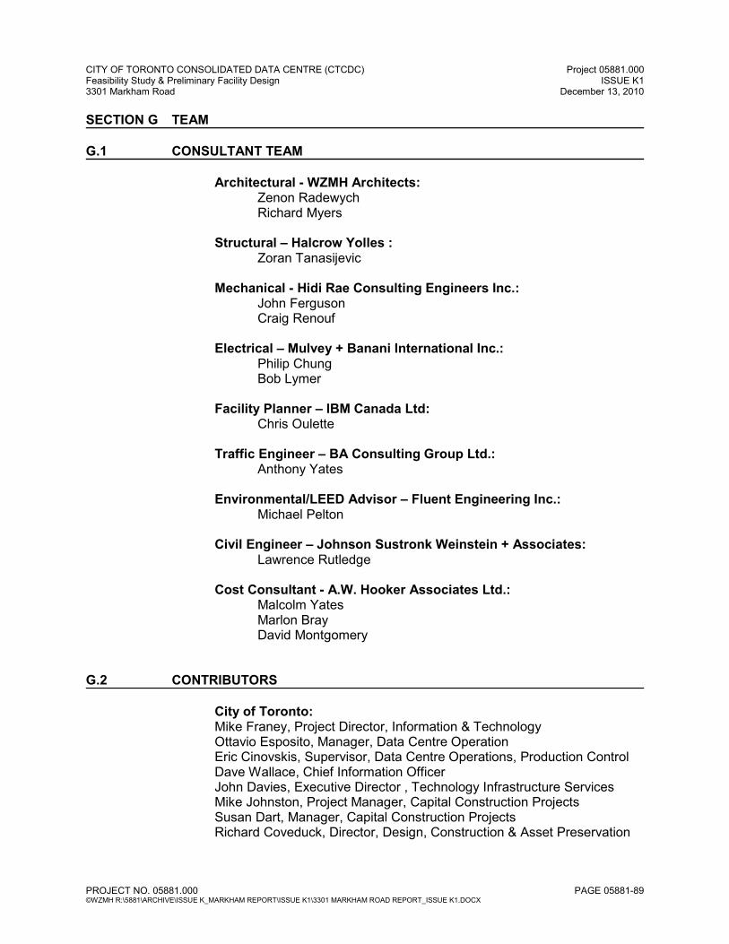
CITY OF TORONTO CONSOLIDATED DATA CENTRE (CTCDC) Project 05881.000 Feasibility Study & Preliminary Facility Design ISSUE K1 3301 Markham Road December 13, 2010
PROJECT NO. 05881.000 PAGE 05881-89 ©WZMH R:\5881\ARCHIVE\ISSUE K_MARKHAM REPORT\ISSUE K1\3301 MARKHAM ROAD REPORT_ISSUE K1.DOCX
SECTION G TEAM
G.1 CONSULTANT TEAM
Architectural - WZMH Architects: Zenon Radewych Richard Myers
Structural – Halcrow Yolles :
Zoran Tanasijevic Mechanical - Hidi Rae Consulting Engineers Inc.:
John Ferguson Craig Renouf
Electrical – Mulvey + Banani International Inc.:
Philip Chung Bob Lymer
Facility Planner – IBM Canada Ltd:
Chris Oulette Traffic Engineer – BA Consulting Group Ltd.:
Anthony Yates Environmental/LEED Advisor – Fluent Engineering Inc.:
Michael Pelton Civil Engineer – Johnson Sustronk Weinstein + Associates:
Lawrence Rutledge Cost Consultant - A.W. Hooker Associates Ltd.:
Malcolm Yates Marlon Bray David Montgomery
G.2 CONTRIBUTORS
City of Toronto: Mike Franey, Project Director, Information & Technology Ottavio Esposito, Manager, Data Centre Operation Eric Cinovskis, Supervisor, Data Centre Operations, Production Control Dave Wallace, Chief Information Officer John Davies, Executive Director , Technology Infrastructure Services Mike Johnston, Project Manager, Capital Construction Projects Susan Dart, Manager, Capital Construction Projects Richard Coveduck, Director, Design, Construction & Asset Preservation

SECTION H BACKGROUND INFORMATION
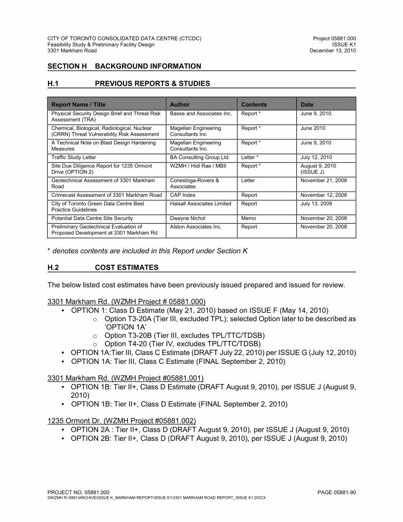
CITY OF TORONTO CONSOLIDATED DATA CENTRE (CTCDC) Project 05881.000 Feasibility Study & Preliminary Facility Design ISSUE K1 3301 Markham Road December 13, 2010
PROJECT NO. 05881.000 PAGE 05881-90 ©WZMH R:\5881\ARCHIVE\ISSUE K_MARKHAM REPORT\ISSUE K1\3301 MARKHAM ROAD REPORT_ISSUE K1.DOCX
SECTION H BACKGROUND INFORMATION H.1 PREVIOUS REPORTS & STUDIES Report Name / Title
Author
Contents
Date
Physical Security Design Brief and Threat Risk Assessment (TRA)
Basse and Associates Inc. Report * June 9, 2010.
Chemical, Biological, Radiological, Nuclear (CRRN) Threat Vulnerability Risk Assessment
Magellan Engineering Consultants Inc
Report * June 2010
A Technical Note on Blast Design Hardening Measures
Magellan Engineering Consultants Inc.
Report * June 9, 2010
Traffic Study Letter BA Consulting Group Ltd. Letter * July 12, 2010
Site Due Diligence Report for 1235 Ormont Drive (OPTION 2)
WZMH / Hidi Rae / MBII Report * August 9, 2010 (ISSUE J)
Geotechnical Assessment of 3301 Markham Road
Conestoga-Rovers & Associates
Letter November 21, 2008
Crimecast Assessment of 3301 Markham Road CAP Index Report November 12, 2008
City of Toronto Green Data Centre Best Practice Guidelines
Halsall Associates Limited Report July 13, 2009
Potential Data Centre Site Security Dwayne Nichol Memo November 20, 2008
Preliminary Geotechnical Evaluation of Proposed Development at 3301 Markham Rd.
Alston Associates Inc. Report November 20, 2008
* denotes contents are included in this Report under Section K H.2 COST ESTIMATES The below listed cost estimates have been previously issued prepared and issued for review. 3301 Markham Rd. (WZMH Project # 05881.000)
• OPTION 1: Class D Estimate (May 21, 2010) based on ISSUE F (May 14, 2010) o Option T3-20A (Tier III, excluded TPL); selected Option later to be described as
‘OPTION 1A’ o Option T3-20B (Tier III, excludes TPL/TTC/TDSB) o Option T4-20 (Tier IV, excludes TPL/TTC/TDSB)
• OPTION 1A:Tier III, Class C Estimate (DRAFT July 22, 2010) per ISSUE G (July 12, 2010) • OPTION 1A: Tier III, Class C Estimate (FINAL September 2, 2010)
3301 Markham Rd. (WZMH Project #05881.001)
• OPTION 1B: Tier II+, Class D Estimate (DRAFT August 9, 2010), per ISSUE J (August 9, 2010)
• OPTION 1B: Tier II+, Class D Estimate (FINAL September 2, 2010) 1235 Ormont Dr. (WZMH Project #05881.002)
• OPTION 2A : Tier II+, Class D (DRAFT August 9, 2010), per ISSUE J (August 9, 2010) • OPTION 2B: Tier II+, Class D (DRAFT August 9, 2010), per ISSUE J (August 9, 2010)
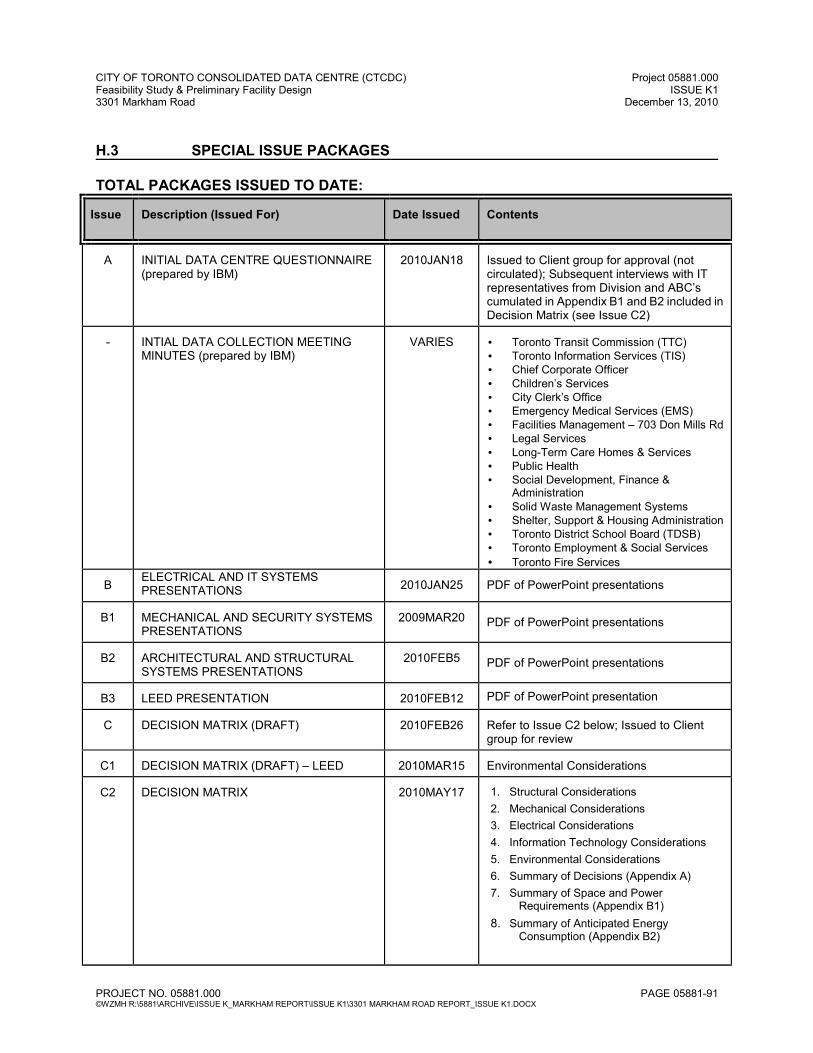
CITY OF TORONTO CONSOLIDATED DATA CENTRE (CTCDC) Project 05881.000 Feasibility Study & Preliminary Facility Design ISSUE K1 3301 Markham Road December 13, 2010
PROJECT NO. 05881.000 PAGE 05881-91 ©WZMH R:\5881\ARCHIVE\ISSUE K_MARKHAM REPORT\ISSUE K1\3301 MARKHAM ROAD REPORT_ISSUE K1.DOCX
H.3 SPECIAL ISSUE PACKAGES TOTAL PACKAGES ISSUED TO DATE: Issue
Description (Issued For)
Date Issued
Contents
A
INITIAL DATA CENTRE QUESTIONNAIRE (prepared by IBM)
2010JAN18
Issued to Client group for approval (not circulated); Subsequent interviews with IT representatives from Division and ABC’s cumulated in Appendix B1 and B2 included in Decision Matrix (see Issue C2)
-
INTIAL DATA COLLECTION MEETING MINUTES (prepared by IBM)
VARIES
• Toronto Transit Commission (TTC) • Toronto Information Services (TIS) • Chief Corporate Officer • Children’s Services • City Clerk’s Office • Emergency Medical Services (EMS) • Facilities Management – 703 Don Mills Rd • Legal Services • Long-Term Care Homes & Services • Public Health • Social Development, Finance &
Administration • Solid Waste Management Systems • Shelter, Support & Housing Administration • Toronto District School Board (TDSB) • Toronto Employment & Social Services
• Toronto Fire Services
B ELECTRICAL AND IT SYSTEMS PRESENTATIONS
2010JAN25
PDF of PowerPoint presentations
B1
MECHANICAL AND SECURITY SYSTEMS PRESENTATIONS
2009MAR20 PDF of PowerPoint presentations
B2
ARCHITECTURAL AND STRUCTURAL SYSTEMS PRESENTATIONS
2010FEB5 PDF of PowerPoint presentations
B3
LEED PRESENTATION
2010FEB12 PDF of PowerPoint presentation
C
DECISION MATRIX (DRAFT)
2010FEB26
Refer to Issue C2 below; Issued to Client group for review
C1
DECISION MATRIX (DRAFT) – LEED
2010MAR15
Environmental Considerations
C2
DECISION MATRIX
2010MAY17
1. Structural Considerations
2. Mechanical Considerations
3. Electrical Considerations
4. Information Technology Considerations
5. Environmental Considerations
6. Summary of Decisions (Appendix A)
7. Summary of Space and Power Requirements (Appendix B1)
8. Summary of Anticipated Energy Consumption (Appendix B2)
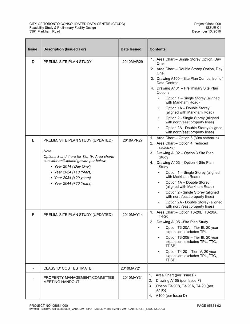
CITY OF TORONTO CONSOLIDATED DATA CENTRE (CTCDC) Project 05881.000 Feasibility Study & Preliminary Facility Design ISSUE K1 3301 Markham Road December 13, 2010
PROJECT NO. 05881.000 PAGE 05881-92 ©WZMH R:\5881\ARCHIVE\ISSUE K_MARKHAM REPORT\ISSUE K1\3301 MARKHAM ROAD REPORT_ISSUE K1.DOCX
Issue
Description (Issued For)
Date Issued
Contents
D
PRELIM. SITE PLAN STUDY
2010MAR29
1. Area Chart – Single Storey Option, Day One
2. Area Chart – Double Storey Option, Day One
3. Drawing A100 – Site Plan Comparison of Data Centres
4. Drawing A101 – Preliminary Site Plan Options
• Option 1 – Single Storey (aligned with Markham Road)
• Option 1A – Double Storey (aligned with Markham Road)
• Option 2 - Single Storey (aligned with north/east property lines)
• Option 2A - Double Storey (aligned with north/east property lines)
E
PRELIM. SITE PLAN STUDY (UPDATED)
Note:
Options 3 and 4 are for Tier IV; Area charts consider anticipated growth per below:
• Year 2014 (‘Day One’) • Year 2024 (+10 Years) • Year 2034 (+20 years) • Year 2044 (+30 Years)
2010APR27
1. Area Chart – Option 3 (30m setbacks)
2. Area Chart – Option 4 (reduced setbacks)
3. Drawing A102 – Option 3 Site Plan Study
4. Drawing A103 – Option 4 Site Plan Study
• Option 1 – Single Storey (aligned with Markham Road)
• Option 1A – Double Storey (aligned with Markham Road)
• Option 2 - Single Storey (aligned with north/east property lines)
• Option 2A - Double Storey (aligned with north/east property lines)
F
PRELIM. SITE PLAN STUDY (UPDATED)
2010MAY14
1. Area Chart – Option T3-20B, T3-20A, T4-20
2. Drawing A105 –Site Plan Study
• Option T3-20A – Tier III, 20 year expansion; excludes TPL
• Option T3-20B – Tier III, 20 year expansion; excludes TPL, TTC, TDSB
• Option T4-20 – Tier IV, 20 year expansion; excludes TPL, TTC, TDSB
-
CLASS ‘D’ COST ESTIMATE
2010MAY21
-
PROPERTY MANAGEMENT COMMITTEE MEETING HANDOUT
2010MAY31
1. Area Chart (per Issue F)
2. Drawing A105 (per Issue F)
3. Option T3-20B, T3-20A, T4-20 (per A105)
4. A100 (per Issue D)
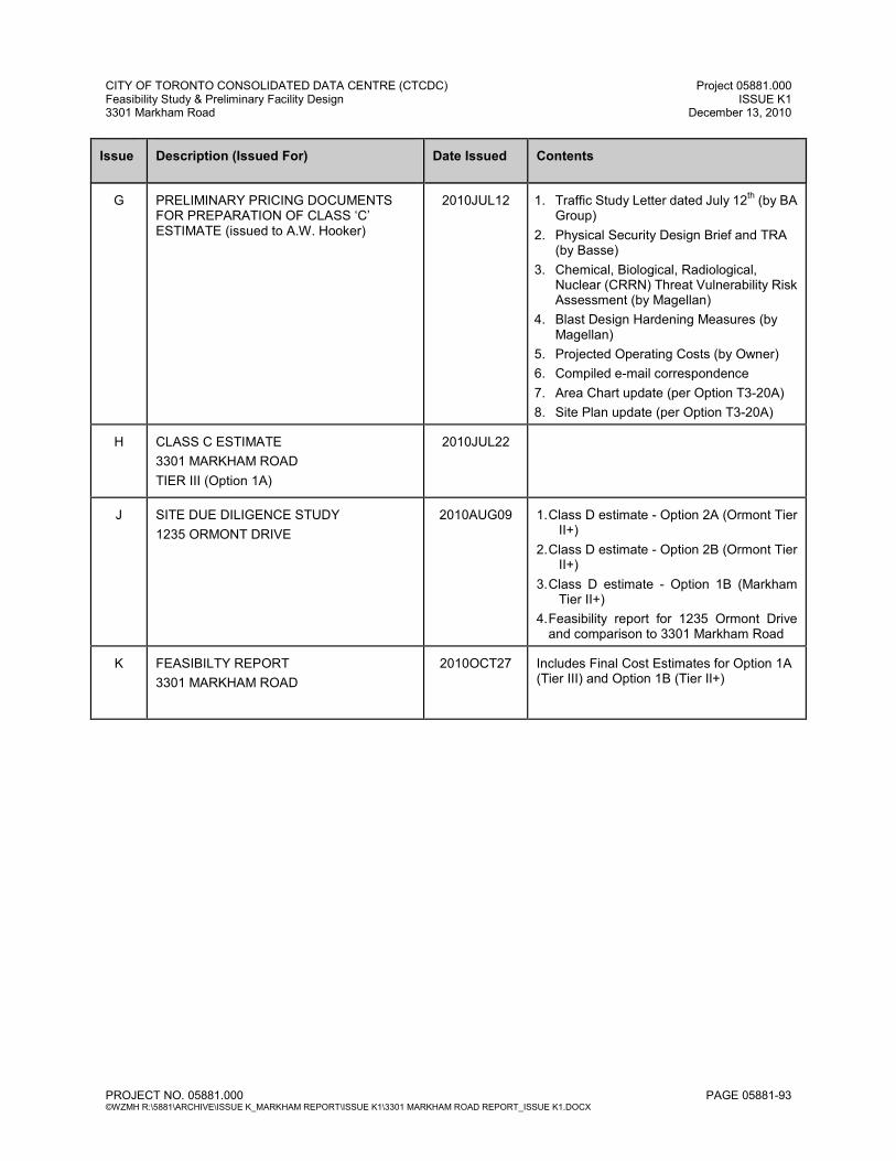
CITY OF TORONTO CONSOLIDATED DATA CENTRE (CTCDC) Project 05881.000 Feasibility Study & Preliminary Facility Design ISSUE K1 3301 Markham Road December 13, 2010
PROJECT NO. 05881.000 PAGE 05881-93 ©WZMH R:\5881\ARCHIVE\ISSUE K_MARKHAM REPORT\ISSUE K1\3301 MARKHAM ROAD REPORT_ISSUE K1.DOCX
Issue
Description (Issued For)
Date Issued
Contents
G
PRELIMINARY PRICING DOCUMENTS FOR PREPARATION OF CLASS ‘C’ ESTIMATE (issued to A.W. Hooker)
2010JUL12
1. Traffic Study Letter dated July 12
th (by BA
Group)
2. Physical Security Design Brief and TRA (by Basse)
3. Chemical, Biological, Radiological, Nuclear (CRRN) Threat Vulnerability Risk Assessment (by Magellan)
4. Blast Design Hardening Measures (by Magellan)
5. Projected Operating Costs (by Owner)
6. Compiled e-mail correspondence
7. Area Chart update (per Option T3-20A)
8. Site Plan update (per Option T3-20A) H
CLASS C ESTIMATE
3301 MARKHAM ROAD
TIER III (Option 1A)
2010JUL22
J
SITE DUE DILIGENCE STUDY
1235 ORMONT DRIVE
2010AUG09
1. Class D estimate - Option 2A (Ormont Tier
II+)
2. Class D estimate - Option 2B (Ormont Tier II+)
3. Class D estimate - Option 1B (Markham Tier II+)
4. Feasibility report for 1235 Ormont Drive and comparison to 3301 Markham Road
K
FEASIBILTY REPORT
3301 MARKHAM ROAD
2010OCT27
Includes Final Cost Estimates for Option 1A (Tier III) and Option 1B (Tier II+)

SECTION J GLOSSARY

CITY OF TORONTO CONSOLIDATED DATA CENTRE (CTCDC) Project 05881.000 Feasibility Study & Preliminary Facility Design ISSUE K1 3301 Markham Road December 13, 2010
PROJECT NO. 05881.000 PAGE 05881-94 ©WZMH R:\5881\ARCHIVE\ISSUE K_MARKHAM REPORT\ISSUE K1\3301 MARKHAM ROAD REPORT_ISSUE K1.DOCX
SECTION J GLOSSARY ASHRAE American Society of Heating, Refrigerating and Air-Conditioning
Engineers BAS Building Automation System BOMA Building Owners and Managers Association (BOMA) of Canada CACF Central Alarm and Control Facility. Special room located within a
building adjacent to the main entrance used by fire fighters to monitor and manage an emergency condition within the complex.
CA Commissioning Agent CCR Computer Control Room CFC Chlorofluorocarbon CRAC Computer Room Air Conditioning Unit CAN/CSA National Standard of Canada designation and Canadian Standards
Association. CUP Central Utilities Plant EPO Emergency Power Off FF&E Fixtures, furnishings and equipment. Movable furniture, fixtures or
other equipment that are have no permanent connection to the structure of a building or utilities.
FM Global FM Global helps safeguard clients' properties through
cost-effective insurance coverage, risk transfer solutions and loss prevention research and engineering.
Go Green Plus BOMA Canada Go Green program, is a national environmental
recognition and certification program for commercial buildings. The overall objective of BOMA Go Green is to encourage as many buildings as possible across Canada to become Go Green certified, and for Go Green to become known as a desirable, reliable standard.
Green Seal Green Seal is an independent non-profit organization offering
environmental certification for products, based on Green Seal standards.
ha Hectares IESNA The Illuminating Engineering Society of North America

CITY OF TORONTO CONSOLIDATED DATA CENTRE (CTCDC) Project 05881.000 Feasibility Study & Preliminary Facility Design ISSUE K1 3301 Markham Road December 13, 2010
PROJECT NO. 05881.000 PAGE 05881-95 ©WZMH R:\5881\ARCHIVE\ISSUE K_MARKHAM REPORT\ISSUE K1\3301 MARKHAM ROAD REPORT_ISSUE K1.DOCX
IPMVP The International Performance Measurement and Verification Protocol
IT Information Technology/Communications/Telecommunications kg Kilogram kPa KiloPascal LANs Local Area Networks
LEED® Leadership in Energy and Environmental Design MW Mega Watts MNECB The Model National Energy Code of Canada for Buildings m² Square Metre N +1 Needs plus one. The minimum needs in terms of mechanical and
electrical infrastructure required for the Data Centre plus one additional redundant component for each mechanical and electrical component engineered.
2 (N+1) 2 Times the (need plus one). OBC Ontario Building Code NBC National Building Code of Canada PDU Power Distribution Unit. An electrical device used to control the
distribution of power to individual loads. Phase 1 2 Year Program Phase 2 5 Year Program Phase 3 7 Year Program Phase 4 10 Year Program Phase 5 15 Year Program psf Pounds per square foot PVC Polyvinyl Chloride RBC Royal Bank of Canada RECC Row End Cable Cabinet
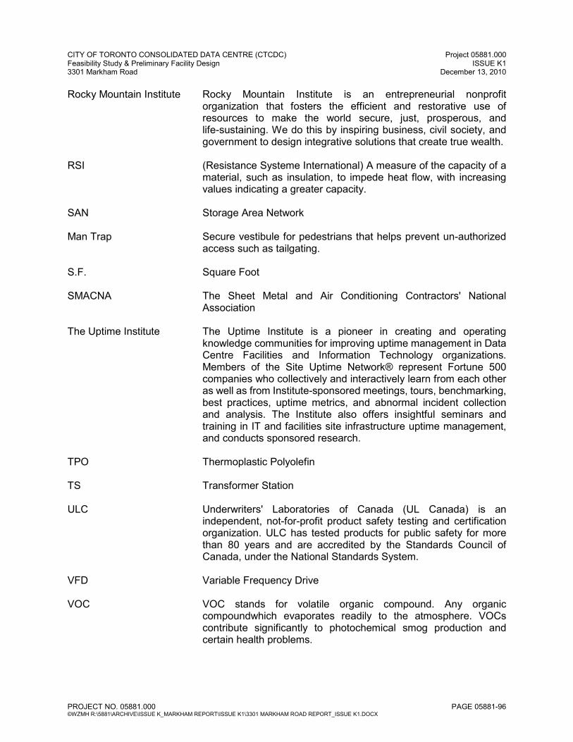
CITY OF TORONTO CONSOLIDATED DATA CENTRE (CTCDC) Project 05881.000 Feasibility Study & Preliminary Facility Design ISSUE K1 3301 Markham Road December 13, 2010
PROJECT NO. 05881.000 PAGE 05881-96 ©WZMH R:\5881\ARCHIVE\ISSUE K_MARKHAM REPORT\ISSUE K1\3301 MARKHAM ROAD REPORT_ISSUE K1.DOCX
Rocky Mountain Institute Rocky Mountain Institute is an entrepreneurial nonprofit organization that fosters the efficient and restorative use of resources to make the world secure, just, prosperous, and life-sustaining. We do this by inspiring business, civil society, and government to design integrative solutions that create true wealth.
RSI (Resistance Systeme International) A measure of the capacity of a
material, such as insulation, to impede heat flow, with increasing values indicating a greater capacity.
SAN Storage Area Network Man Trap Secure vestibule for pedestrians that helps prevent un-authorized
access such as tailgating. S.F. Square Foot SMACNA The Sheet Metal and Air Conditioning Contractors' National
Association The Uptime Institute The Uptime Institute is a pioneer in creating and operating
knowledge communities for improving uptime management in Data Centre Facilities and Information Technology organizations. Members of the Site Uptime Network® represent Fortune 500 companies who collectively and interactively learn from each other as well as from Institute-sponsored meetings, tours, benchmarking, best practices, uptime metrics, and abnormal incident collection and analysis. The Institute also offers insightful seminars and training in IT and facilities site infrastructure uptime management, and conducts sponsored research.
TPO Thermoplastic Polyolefin TS Transformer Station ULC Underwriters' Laboratories of Canada (UL Canada) is an
independent, not-for-profit product safety testing and certification organization. ULC has tested products for public safety for more than 80 years and are accredited by the Standards Council of Canada, under the National Standards System.
VFD Variable Frequency Drive VOC VOC stands for volatile organic compound. Any organic
compoundwhich evaporates readily to the atmosphere. VOCs contribute significantly to photochemical smog production and certain health problems.
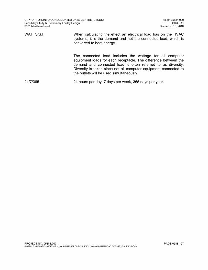
CITY OF TORONTO CONSOLIDATED DATA CENTRE (CTCDC) Project 05881.000 Feasibility Study & Preliminary Facility Design ISSUE K1 3301 Markham Road December 13, 2010
PROJECT NO. 05881.000 PAGE 05881-97 ©WZMH R:\5881\ARCHIVE\ISSUE K_MARKHAM REPORT\ISSUE K1\3301 MARKHAM ROAD REPORT_ISSUE K1.DOCX
WATTS/S.F. When calculating the effect an electrical load has on the HVAC systems, it is the demand and not the connected load, which is converted to heat energy.
The connected load includes the wattage for all computer equipment loads for each receptacle. The difference between the demand and connected load is often referred to as diversity. Diversity is taken since not all computer equipment connected to the outlets will be used simultaneously.
24/7/365 24 hours per day, 7 days per week, 365 days per year.


![Toronto Hydro Corporation · Toronto Hydro Corporation NOTES TO INTERIM CONSOLIDATED FINANCIAL STATEMENTS [all tabular amounts in thousands of dollars, unaudited] September 30, …](https://static.fdocuments.net/doc/165x107/5ae50e617f8b9a5b348f97dd/toronto-hydro-corporation-hydro-corporation-notes-to-interim-consolidated-financial.jpg)