CITY OF SUNNYVALE DESIGN INFORMATION … · 3.4 Primary Sedimentation Tanks ... – A surface...
103
2700 YGNACIO VALLEY ROAD • SUITE 300 • WALNUT CREEK, CALIFORNIA 94598 • (925) 932-1710 • FAX (925) 930-0208 pw://Carollo/Documents/Client/CA/Sunnyvale/9265A10/Deliverables/Preliminary Design Report/DIM No 7-Primary Sedimentation Tanks.docx CITY OF SUNNYVALE PRIMARY TREATMENT DESIGN DESIGN INFORMATION MEMORANDUM NO. 7 PRIMARY SEDIMENTATION TANKS FINAL July 2014 Prepared By: ______________________ Malar Perinpanayagam, P.E. Reviewed By: ______________________ Dana Hunt, P.E. Reviewed By: ______________________ Hany Gerges, P.E. Reviewed By: ______________________ Craig Olson, P.E. Reviewed By: ______________________ Jamel Demir, P.E. Reviewed By: ______________________ James Wickstrom, P.E.
-
Upload
nguyenxuyen -
Category
Documents
-
view
214 -
download
0
Transcript of CITY OF SUNNYVALE DESIGN INFORMATION … · 3.4 Primary Sedimentation Tanks ... – A surface...
2 7 0 0 Y G N A C I O V A L L E Y R O A D • S U I T E 3 0 0 • W A L N U T C R E E K , C A L I F O R N I A 9 4 5 9 8 • ( 9 2 5 ) 9 3 2 - 1 7 1 0 • F A X ( 9 2 5 ) 9 3 0 - 0 2 0 8 pw://Carollo/Documents/Client/CA/Sunnyvale/9265A10/Deliverables/Preliminary Design Report/DIM No 7-Primary Sedimentation Tanks.docx
CITY OF SUNNYVALE
PRIMARY TREATMENT DESIGN
DESIGN INFORMATION MEMORANDUM NO. 7
PRIMARY SEDIMENTATION TANKS
FINAL July 2014
Prepared By: ______________________ Malar Perinpanayagam, P.E.
Reviewed By: ______________________ Dana Hunt, P.E.
Reviewed By: ______________________ Hany Gerges, P.E.
Reviewed By: ______________________ Craig Olson, P.E.
Reviewed By: ______________________ Jamel Demir, P.E.
Reviewed By: ______________________ James Wickstrom, P.E.

July 2014 - FINAL i pw://Carollo/Documents/Client/CA/Sunnyvale/9265A10/Deliverables/Preliminary Design Report/DIM No 7-Primary Sedimentation Tanks.docx
CITY OF SUNNYVALE
PRIMARY TREATMENT DESIGN
DESIGN INFORMATION MEMORANDUM NO. 7
PRIMARY SEDIMENTATION TANKS
TABLE OF CONTENTS Page No.
1.0 PURPOSE ............................................................................................................ 7-3
2.0 BACKGROUND .................................................................................................... 7-3 Update to Primary Treatment TM .............................................................. 7-5 2.1
3.0 BASIS OF DESIGN ............................................................................................... 7-6 Primary Influent Conveyance ................................................................... 7-10 3.1 Primary Influent Channel and Flow Distribution to PSTs .......................... 7-10 3.2 Primary Influent Channel Pre-aeration ..................................................... 7-13 3.3 Primary Sedimentation Tanks .................................................................. 7-13 3.4 Primary Effluent Collection and Discharge ............................................... 7-14 3.5 Sludge Collection and Pumping ............................................................... 7-14 3.6 Scum Collection and Pumping ................................................................. 7-15 3.7 Sludge/Scum Pre-heating ........................................................................ 7-15 3.8
4.0 ELECTRICAL REQUIREMENTS ........................................................................ 7-16
5.0 CONTROL PHILOSOPHY OVERVIEW .............................................................. 7-18 Influent Channel ...................................................................................... 7-18 5.1 PST Influent Gates .................................................................................. 7-18 5.2 Pre-aeration Blowers ............................................................................... 7-19 5.3 Tank Effluent Channel Gates ................................................................... 7-19 5.4 Sludge Collector Drive ............................................................................. 7-19 5.5 Effluent Channel Gates ........................................................................... 7-19 5.6 Primary Sludge Pumping ......................................................................... 7-19 5.7 Primary Scum Collection ......................................................................... 7-20 5.8 Primary Scum Pumping ........................................................................... 7-20 5.9
6.0 EQUIPMENT PROCUREMENT .......................................................................... 7-20
7.0 PRIMARY TREATMENT FACILITY SYSTEM LAYOUT ...................................... 7-21
8.0 ANCILLARY FACILITIES .................................................................................... 7-22 Potable Water ......................................................................................... 7-22 8.1 Utility Water ............................................................................................. 7-22 8.2 Plant Air................................................................................................... 7-22 8.3 HVAC ...................................................................................................... 7-22 8.4 Fire Protection ......................................................................................... 7-31 8.5 Drainage.................................................................................................. 7-31 8.6
9.0 SUMMARY ......................................................................................................... 7-32
July 2014 - FINAL ii pw://Carollo/Documents/Client/CA/Sunnyvale/9265A10/Deliverables/Preliminary Design Report/DIM No 7-Primary Sedimentation Tanks.docx
LIST OF APPENDICES A – Equipment Data Sheets and Cut Sheets for Key Process Equipment B – DIM Meeting 2 Minutes (April 17, 2014) C – Primary Sedimentation Tank Influent Channel Modeling TM
LIST OF TABLES Table 7.1 Design Criteria – Primary Treatment System ............................................... 7-6 Table 7.2 Electrical Classification by Sub-area .......................................................... 7-17
LIST OF FIGURES Figure 7.1 Primary Sedimentation Tanks Process Flow Diagram ............................... 7-11 Figure 7.2 Primary Sedimentation Tanks Upper Plan ................................................. 7-23 Figure 7.3 Primary Sedimentation Tanks Lower Plan ................................................. 7-25 Figure 7.4 Primary Sedimentation Tanks Enlarged Plan ............................................. 7-27 Figure 7.5 Primary Sedimentation Tanks Sections ..................................................... 7-29
July 2014 - FINAL 7-3 pw://Carollo/Documents/Client/CA/Sunnyvale/9265A10/Deliverables/Preliminary Design Report/DIM No 7-Primary Sedimentation Tanks.docx
Design Information Memorandum No. 7 PRIMARY SEDIMENTATION TANKS
1.0 PURPOSE The purpose of this Design Information Memorandum (DIM) is to provide the basis of design for the new primary sedimentation tanks (PSTs) and sludge and scum handling at the City of Sunnyvale’s (City’s) Water Pollution Control Plant (WPCP). The primary treatment separates and removes suspended solids (SS), floatables including oil and grease, and biological oxygen demand (BOD) associated with SS and floatables. Sludge and scum pumps convey settled solids and floatables from the PSTs to the digesters, respectively.
2.0 BACKGROUND As part of the Master Plan, Carollo/HDR developed Technical Memorandum Primary Treatment: Master Plan (March 2014) that presented an analysis and selection of process alternatives for primary treatment at the City’s WPCP. Primary treatment processes were selected based on providing the needed improvements through buildout (2035) to meet the City’s goals and objectives. Key findings and recommendations pertaining to the PSTs from the Technical Memorandum Primary Treatment: Master Plan dated March 2014 are described below.
• Primary treatment should be implemented because it is not cost effective to construct and operate a new secondary treatment system without PSTs. Another advantage to PSTs is that the City already has digesters and primary sludge is known to have a high energy value.
• It is recommended that construction of the PSTs not be phased since an additional construction cost of approximately $2.5 million will be added to the overall cost of the PSTs if they are constructed in two phases (five PSTs now and one PST at a later date). In addition, by constructing all six PSTs now, the City will obtain additional reliability and flexibility. The recommended PSTs will be designed to accommodate the 2035 maximum month (MM) flow of 26.2 million gallons per day (mgd) and should be able to handle minimum and peak flow conditions.
• Primary Sedimentation Tanks: – A surface overflow rate (OFR) of 2,000 gallons per day per square foot (gpd/sf),
with all tanks in service at MM flow in 2035 was selected for design basis. – Six (6) PSTs will be constructed to provide proper operation and sufficient
flexibility and redundancy.
July 2014 - FINAL 7-4 pw://Carollo/Documents/Client/CA/Sunnyvale/9265A10/Deliverables/Preliminary Design Report/DIM No 7-Primary Sedimentation Tanks.docx
• Chemically Enhanced Primary Treatment (CEPT): – The primary treatment design will include provisions for a permanent CEPT
facility. CEPT will only be used on an “as-needed” basis under high loading conditions (MM or higher) and when one PST is out of service. The facilities also provide additional flexibility and redundancy to the WPCP staff. In addition, CEPT may be used under operating scenarios in the future, such as during split treatment when one aeration tank is out of service and under future operating conditions if phosphorous removal is implemented.
– The CEPT facility will be designed for a dose of 20 mg /L of ferric chloride and 0.2 milligrams per liter (mg/L) of polymer. The chemical addition point will be further evaluated during preliminary design, however at this time chemical addition at the PST influent channel is envisioned.
• Primary Influent: – The PSTs will include an influent channel which will be designed to convey and
distribute peak flows to the online PSTs. The channel will be aerated with coarse bubble aeration. Influent flow distribution will be further analyzed and developed in preliminary design.
• Primary Effluent: – The PSTs will include an effluent channel which will collect effluent from
overflow weirs and launders within the tanks. The channel will be designed to convey peak flows. Effluent collection will be further analyzed and evaluated in preliminary design.
– Primary effluent will be conveyed to the existing Oxidation Ponds by constructing a new primary effluent pipeline. Provisions for connection to future primary effluent equalization and the future secondary treatment system will be included. This work will be coordinated with the work being performed under the Emergency Flow Management Improvements project.
• Primary Sludge:
− A full length chain and flight sludge collector and a cross collector will be provided in each PST. One (1) sludge hopper per tank will be provided for sludge collection.
– The primary sludge hopper and pumps will be designed for thick sludge. No provisions for thin sludge pumping will be provided.
– One (1) duty plus one standby sludge pump will serve two (2) PST sludge hoppers. A total of six (6) sludge pumps will be provided.
• Primary Scum: – Return flight skimming will be used for scum removal.
July 2014 - FINAL 7-5 pw://Carollo/Documents/Client/CA/Sunnyvale/9265A10/Deliverables/Preliminary Design Report/DIM No 7-Primary Sedimentation Tanks.docx
– One scum box will collect scum from three (3) PSTs. A total of two scum boxes will be constructed.
– Scum pumping will include one (1) duty and one (1) standby pump for each scum box. A total of four (4) pumps will be provided.
• Odor Control (details presented in draft DIM No. 9 Odor Control and HVAC, July 2014): – Provide a single, package-type bioscrubber system to treat odors collected from
both the preliminary and primary treatment process areas. – Locate the odor control system near the preliminary and primary treatment
processes to simplify the odor ducting design. – Include the following provisions to adequately contain and exhaust odors
generated at the primary treatment facility:
♦ Cover the PST influent/effluent channels and PST launder area (the area where primary effluent flows over weirs and is collected in troughs). Include provisions to cover the entire PSTs, should further odor mitigation be required in the future. Include provisions for corrosion protection for all covered areas (e.g., use of stainless steel and concrete coatings).
♦ Install exhaust fans to extract enough air from the covered and enclosed areas to prevent fugitive emissions and convey it to the odor control system.
• Ventilation: – Install a ventilation system for areas that will be accessed by personnel to
provide proper ventilation required for worker safety.
Update to Primary Treatment TM 2.1
The Technical Memorandum Primary Treatment: Master Plan (March 2014) presented one sludge hopper per PST and a cross collector to rake sludge brought by the chain and flight sludge collector to the sludge hopper. In addition one duty and one standby sludge pump will be provided per two PSTs. The TM reviewers were concerned about the concept of using one duty and one standby pump for two sludge hoppers (two PSTs). HDR revisited the number of sludge pumps provided for sludge pumping and agreed with the reviewers’ comment to provide more sludge pumps. If more sludge pumps were added (nine total), it was possible to eliminate the cross collector and add another sludge hopper per tank (two hoppers per tank).
The recommendations made as part of the Master Plan Preliminary Treatment TM were incorporated into the conceptual design of the influent pump station presented in this DIM, except as follows:
July 2014 - FINAL 7-6 pw://Carollo/Documents/Client/CA/Sunnyvale/9265A10/Deliverables/Preliminary Design Report/DIM No 7-Primary Sedimentation Tanks.docx
• Provide two sludge hoppers per PST, no cross collectors. A total of twelve (12) sludge hoppers will be provided.
• Provide one duty and one shared standby sludge pump per PST. A total of nine (9) sludge pumps will be provided.
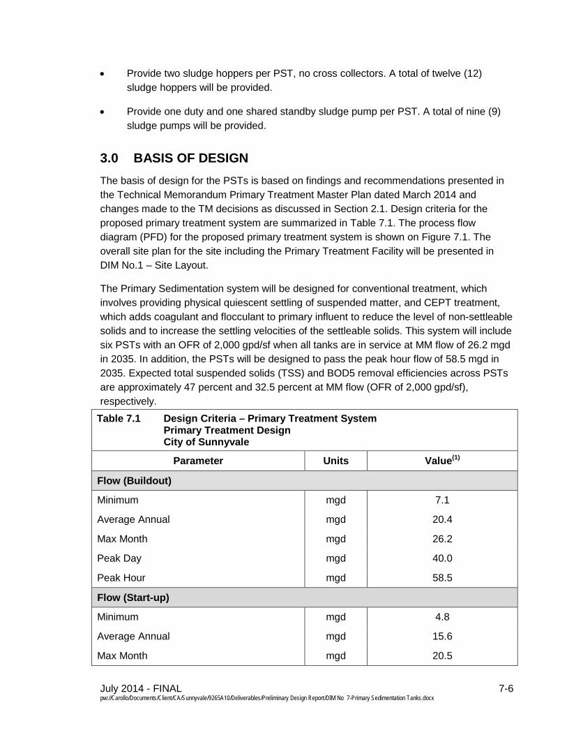
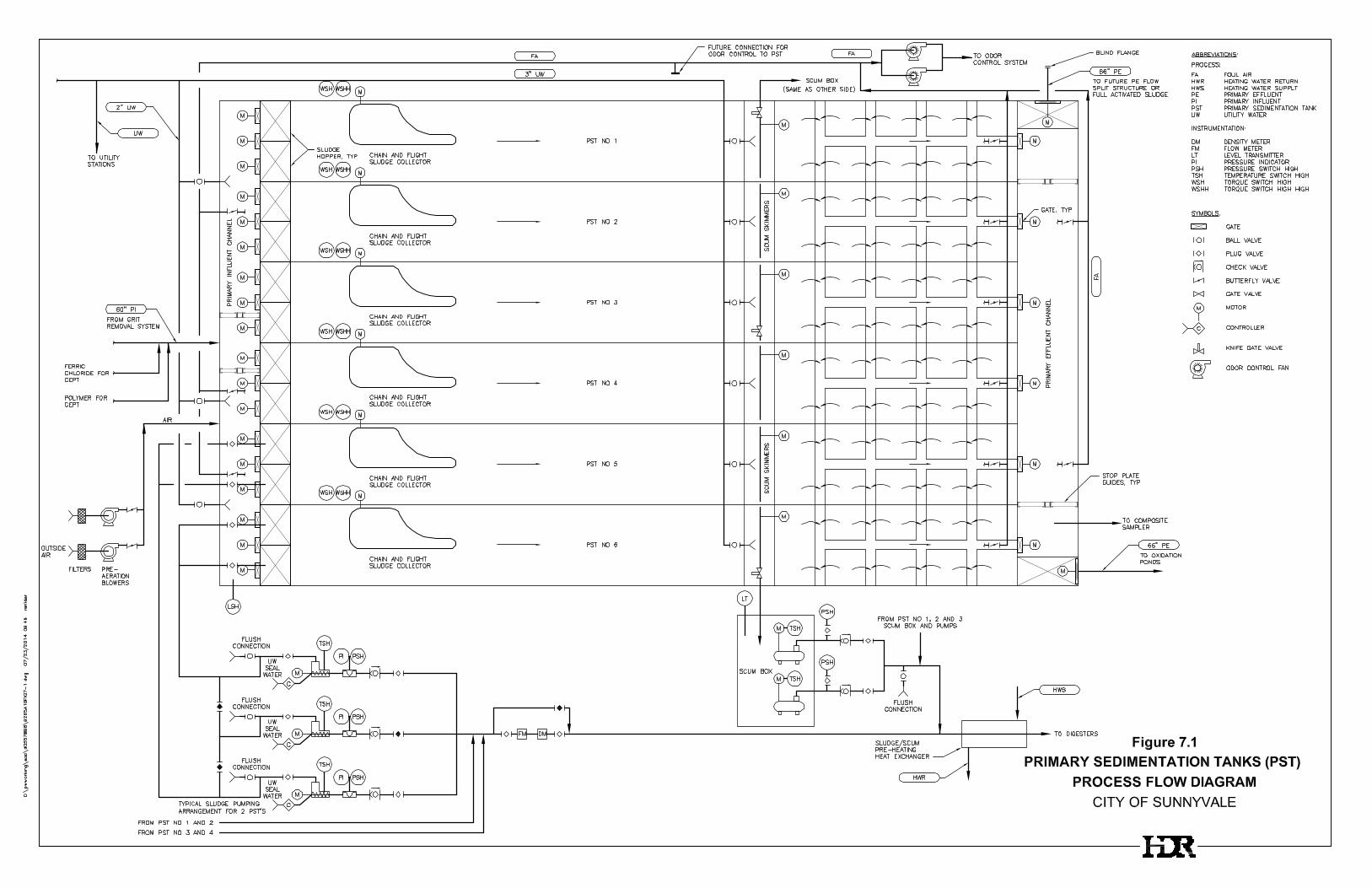
3.0 BASIS OF DESIGN The basis of design for the PSTs is based on findings and recommendations presented in the Technical Memorandum Primary Treatment Master Plan dated March 2014 and changes made to the TM decisions as discussed in Section 2.1. Design criteria for the proposed primary treatment system are summarized in Table 7.1. The process flow diagram (PFD) for the proposed primary treatment system is shown on Figure 7.1. The overall site plan for the site including the Primary Treatment Facility will be presented in DIM No.1 – Site Layout.
The Primary Sedimentation system will be designed for conventional treatment, which involves providing physical quiescent settling of suspended matter, and CEPT treatment, which adds coagulant and flocculant to primary influent to reduce the level of non-settleable solids and to increase the settling velocities of the settleable solids. This system will include six PSTs with an OFR of 2,000 gpd/sf when all tanks are in service at MM flow of 26.2 mgd in 2035. In addition, the PSTs will be designed to pass the peak hour flow of 58.5 mgd in 2035. Expected total suspended solids (TSS) and BOD5 removal efficiencies across PSTs are approximately 47 percent and 32.5 percent at MM flow (OFR of 2,000 gpd/sf), respectively.
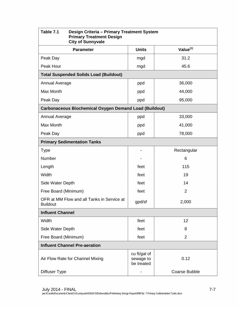
Table 7.1 Design Criteria – Primary Treatment System Primary Treatment Design City of Sunnyvale
Parameter Units Value(1)
Flow (Buildout)
Minimum mgd 7.1
Average Annual mgd 20.4
Max Month mgd 26.2
Peak Day mgd 40.0
Peak Hour mgd 58.5
Flow (Start-up)
Minimum mgd 4.8
Average Annual mgd 15.6
Max Month mgd 20.5
July 2014 - FINAL 7-7 pw://Carollo/Documents/Client/CA/Sunnyvale/9265A10/Deliverables/Preliminary Design Report/DIM No 7-Primary Sedimentation Tanks.docx
Table 7.1 Design Criteria – Primary Treatment System Primary Treatment Design City of Sunnyvale
Parameter Units Value(1)
Peak Day mgd 31.2
Peak Hour mgd 45.6
Total Suspended Solids Load (Buildout)
Annual Average ppd 36,000
Max Month ppd 44,000
Peak Day ppd 95,000
Carbonaceous Biochemical Oxygen Demand Load (Buildout)
Annual Average ppd 33,000
Max Month ppd 41,000
Peak Day ppd 78,000
Primary Sedimentation Tanks
Type - Rectangular
Number - 6
Length feet 115
Width feet 19
Side Water Depth feet 14
Free Board (Minimum) feet 2
OFR at MM Flow and all Tanks in Service at Buildout gpd/sf 2,000
Influent Channel
Width feet 12
Side Water Depth feet 8
Free Board (Minimum) feet 2
Influent Channel Pre-aeration
Air Flow Rate for Channel Mixing cu ft/gal of sewage to be treated
0.12
Diffuser Type - Coarse Bubble
July 2014 - FINAL 7-8 pw://Carollo/Documents/Client/CA/Sunnyvale/9265A10/Deliverables/Preliminary Design Report/DIM No 7-Primary Sedimentation Tanks.docx
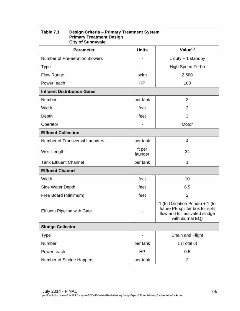
Table 7.1 Design Criteria – Primary Treatment System Primary Treatment Design City of Sunnyvale
Parameter Units Value(1)
Number of Pre-aeration Blowers - 1 duty + 1 standby
Type - High Speed Turbo
Flow Range scfm 2,500
Power, each HP 100
Influent Distribution Gates
Number per tank 3
Width feet 2
Depth feet 3
Operator - Motor
Effluent Collection
Number of Transversal Launders per tank 4
Weir Length ft per launder 34
Tank Effluent Channel per tank 1
Effluent Channel
Width feet 10
Side Water Depth feet 6.5
Free Board (Minimum) feet 2
Effluent Pipeline with Gate -
1 (to Oxidation Ponds) + 1 (to future PE splitter box for split flow and full activated sludge
with diurnal EQ)
Sludge Collector
Type - Chain and Flight
Number per tank 1 (Total 6)
Power, each HP 0.5
Number of Sludge Hoppers per tank 2
July 2014 - FINAL 7-9 pw://Carollo/Documents/Client/CA/Sunnyvale/9265A10/Deliverables/Preliminary Design Report/DIM No 7-Primary Sedimentation Tanks.docx
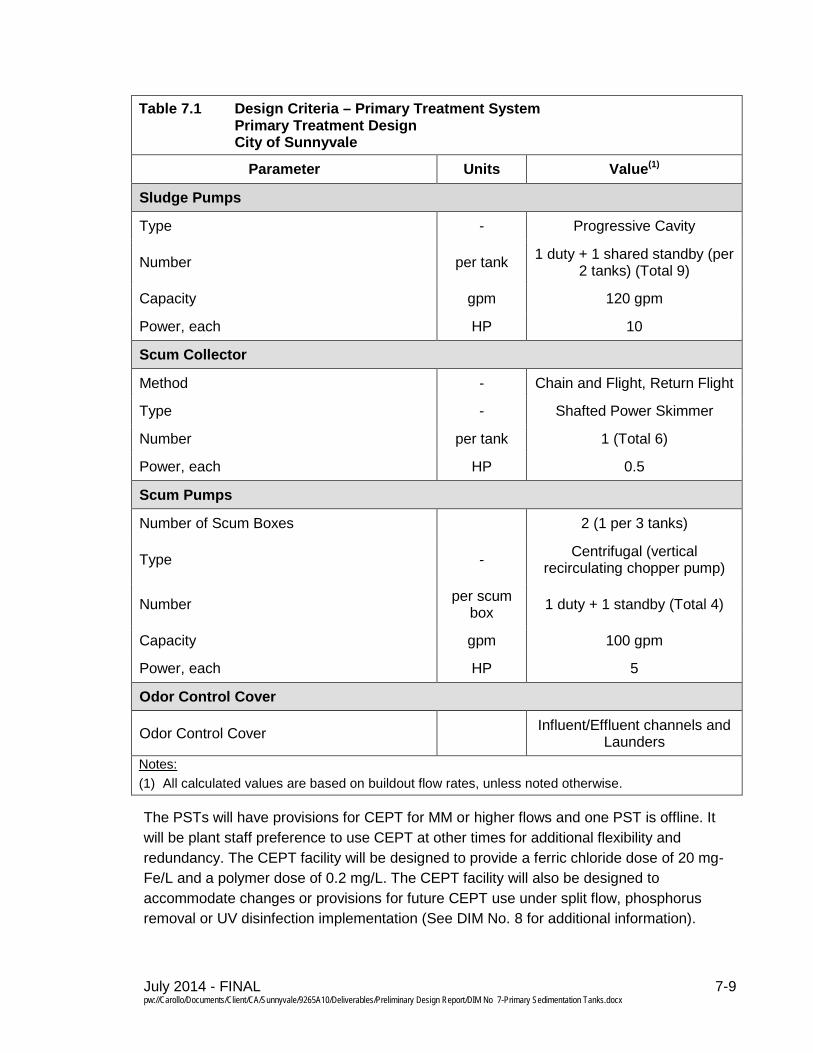
Table 7.1 Design Criteria – Primary Treatment System Primary Treatment Design City of Sunnyvale
Parameter Units Value(1)
Sludge Pumps
Type - Progressive Cavity
Number per tank 1 duty + 1 shared standby (per 2 tanks) (Total 9)
Capacity gpm 120 gpm
Power, each HP 10
Scum Collector
Method - Chain and Flight, Return Flight
Type - Shafted Power Skimmer
Number per tank 1 (Total 6)
Power, each HP 0.5
Scum Pumps
Number of Scum Boxes 2 (1 per 3 tanks)
Type - Centrifugal (vertical recirculating chopper pump)
Number per scum box 1 duty + 1 standby (Total 4)
Capacity gpm 100 gpm
Power, each HP 5
Odor Control Cover
Odor Control Cover Influent/Effluent channels and Launders
Notes: (1) All calculated values are based on buildout flow rates, unless noted otherwise.
The PSTs will have provisions for CEPT for MM or higher flows and one PST is offline. It will be plant staff preference to use CEPT at other times for additional flexibility and redundancy. The CEPT facility will be designed to provide a ferric chloride dose of 20 mg-Fe/L and a polymer dose of 0.2 mg/L. The CEPT facility will also be designed to accommodate changes or provisions for future CEPT use under split flow, phosphorus removal or UV disinfection implementation (See DIM No. 8 for additional information).
July 2014 - FINAL 7-10 pw://Carollo/Documents/Client/CA/Sunnyvale/9265A10/Deliverables/Preliminary Design Report/DIM No 7-Primary Sedimentation Tanks.docx
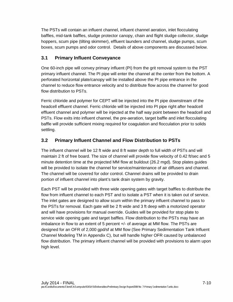
The PSTs will contain an influent channel, influent channel aeration, inlet flocculating baffles, mid-tank baffles, sludge protector canopy, chain and flight sludge collector, sludge hoppers, scum pipe (tilting skimmer), effluent launders and channel, sludge pumps, scum boxes, scum pumps and odor control. Details of above components are discussed below.
Primary Influent Conveyance 3.1
One 60-inch pipe will convey primary influent (PI) from the grit removal system to the PST primary influent channel. The PI pipe will enter the channel at the center from the bottom. A perforated horizontal plate/canopy will be installed above the PI pipe entrance in the channel to reduce flow entrance velocity and to distribute flow across the channel for good flow distribution to PSTs.
Ferric chloride and polymer for CEPT will be injected into the PI pipe downstream of the headcell effluent channel. Ferric chloride will be injected into PI pipe right after headcell effluent channel and polymer will be injected at the half way point between the headcell and PSTs. Flow exits into influent channel, the pre-aeration, target baffle and inlet flocculating baffle will provide sufficient mixing required for coagulation and flocculation prior to solids settling.
Primary Influent Channel and Flow Distribution to PSTs 3.2
The influent channel will be 12 ft wide and 8 ft water depth to full width of PSTs and will maintain 2 ft of free board. The size of channel will provide flow velocity of 0.42 ft/sec and 5 minute detention time at the projected MM flow at buildout (26.2 mgd). Stop plates guides will be provided to isolate the channel for service/maintenance of air diffusers and channel. The channel will be covered for odor control. Channel drains will be provided to drain portion of influent channel into plant’s tank drain system by gravity.
Each PST will be provided with three wide opening gates with target baffles to distribute the flow from influent channel to each PST and to isolate a PST when it is taken out of service. The inlet gates are designed to allow scum within the primary influent channel to pass to the PSTs for removal. Each gate will be 2 ft wide and 3 ft deep with a motorized operator and will have provisions for manual override. Guides will be provided for stop plate to service wide opening gate and target baffles. Flow distribution to the PSTs may have an imbalance in flow to an extent of 5 percent +/- of average at MM flow. The PSTs are designed for an OFR of 2,000 gpd/sf at MM flow (See Primary Sedimentation Tank Influent Channel Modeling TM in Appendix C), but will handle higher OFR caused by unbalanced flow distribution. The primary influent channel will be provided with provisions to alarm upon high level.

July 2014 - FINAL 7-13 pw://Carollo/Documents/Client/CA/Sunnyvale/9265A10/Deliverables/Preliminary Design Report/DIM No 7-Primary Sedimentation Tanks.docx
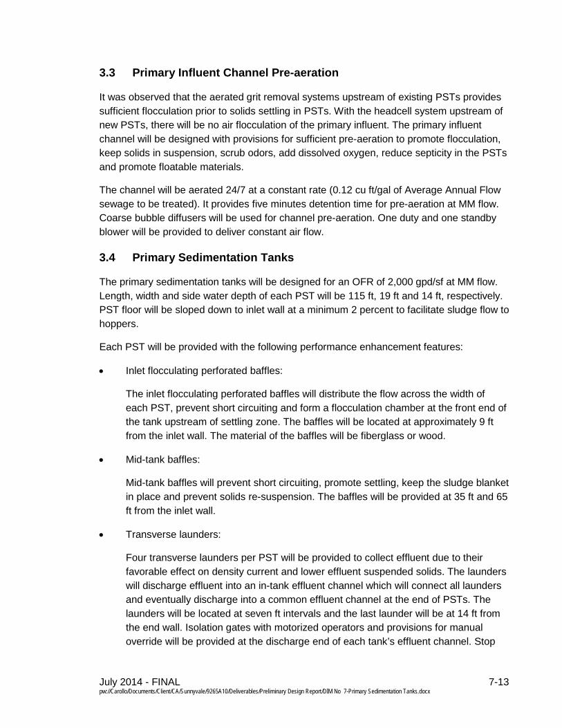
Primary Influent Channel Pre-aeration 3.3
It was observed that the aerated grit removal systems upstream of existing PSTs provides sufficient flocculation prior to solids settling in PSTs. With the headcell system upstream of new PSTs, there will be no air flocculation of the primary influent. The primary influent channel will be designed with provisions for sufficient pre-aeration to promote flocculation, keep solids in suspension, scrub odors, add dissolved oxygen, reduce septicity in the PSTs and promote floatable materials.
The channel will be aerated 24/7 at a constant rate (0.12 cu ft/gal of Average Annual Flow sewage to be treated). It provides five minutes detention time for pre-aeration at MM flow. Coarse bubble diffusers will be used for channel pre-aeration. One duty and one standby blower will be provided to deliver constant air flow.
Primary Sedimentation Tanks 3.4
The primary sedimentation tanks will be designed for an OFR of 2,000 gpd/sf at MM flow. Length, width and side water depth of each PST will be 115 ft, 19 ft and 14 ft, respectively. PST floor will be sloped down to inlet wall at a minimum 2 percent to facilitate sludge flow to hoppers.
Each PST will be provided with the following performance enhancement features:
• Inlet flocculating perforated baffles:
The inlet flocculating perforated baffles will distribute the flow across the width of each PST, prevent short circuiting and form a flocculation chamber at the front end of the tank upstream of settling zone. The baffles will be located at approximately 9 ft from the inlet wall. The material of the baffles will be fiberglass or wood.
• Mid-tank baffles:
Mid-tank baffles will prevent short circuiting, promote settling, keep the sludge blanket in place and prevent solids re-suspension. The baffles will be provided at 35 ft and 65 ft from the inlet wall.
• Transverse launders:
Four transverse launders per PST will be provided to collect effluent due to their favorable effect on density current and lower effluent suspended solids. The launders will discharge effluent into an in-tank effluent channel which will connect all launders and eventually discharge into a common effluent channel at the end of PSTs. The launders will be located at seven ft intervals and the last launder will be at 14 ft from the end wall. Isolation gates with motorized operators and provisions for manual override will be provided at the discharge end of each tank’s effluent channel. Stop
July 2014 - FINAL 7-14 pw://Carollo/Documents/Client/CA/Sunnyvale/9265A10/Deliverables/Preliminary Design Report/DIM No 7-Primary Sedimentation Tanks.docx
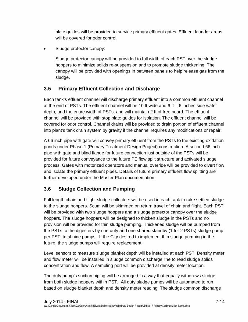
plate guides will be provided to service primary effluent gates. Effluent launder areas will be covered for odor control.
• Sludge protector canopy:
Sludge protector canopy will be provided to full width of each PST over the sludge hoppers to minimize solids re-suspension and to promote sludge thickening. The canopy will be provided with openings in between panels to help release gas from the sludge.
Primary Effluent Collection and Discharge 3.5
Each tank‘s effluent channel will discharge primary effluent into a common effluent channel at the end of PSTs. The effluent channel will be 10 ft wide and 6 ft – 6 inches side water depth, and the entire width of PSTs; and will maintain 2 ft of free board. The effluent channel will be provided with stop plate guides for isolation. The effluent channel will be covered for odor control. Channel drains will be provided to drain portion of effluent channel into plant’s tank drain system by gravity if the channel requires any modifications or repair.
A 66 inch pipe with gate will convey primary effluent from the PSTs to the existing oxidation ponds under Phase 1 (Primary Treatment Design Project) construction. A second 66 inch pipe with gate and blind flange for future connection just outside of the PSTs will be provided for future conveyance to the future PE flow split structure and activated sludge process. Gates with motorized operators and manual override will be provided to divert flow and isolate the primary effluent pipes. Details of future primary effluent flow splitting are further developed under the Master Plan documentation.
Sludge Collection and Pumping 3.6
Full length chain and flight sludge collectors will be used in each tank to rake settled sludge to the sludge hoppers. Scum will be skimmed on return travel of chain and flight. Each PST will be provided with two sludge hoppers and a sludge protector canopy over the sludge hoppers. The sludge hoppers will be designed to thicken sludge in the PSTs and no provision will be provided for thin sludge pumping. Thickened sludge will be pumped from the PSTs to the digesters by one duty and one shared standby (1 for 2 PSTs) sludge pump per PST, total nine pumps. If the City desired to implement thin sludge pumping in the future, the sludge pumps will require replacement.
Level sensors to measure sludge blanket depth will be installed at each PST. Density meter and flow meter will be installed in sludge common discharge line to read sludge solids concentration and flow. A sampling port will be provided at density meter location.
The duty pump’s suction piping will be arranged in a way that equally withdraws sludge from both sludge hoppers within PST. All duty sludge pumps will be automated to run based on sludge blanket depth and density meter reading. The sludge common discharge
July 2014 - FINAL 7-15 pw://Carollo/Documents/Client/CA/Sunnyvale/9265A10/Deliverables/Preliminary Design Report/DIM No 7-Primary Sedimentation Tanks.docx
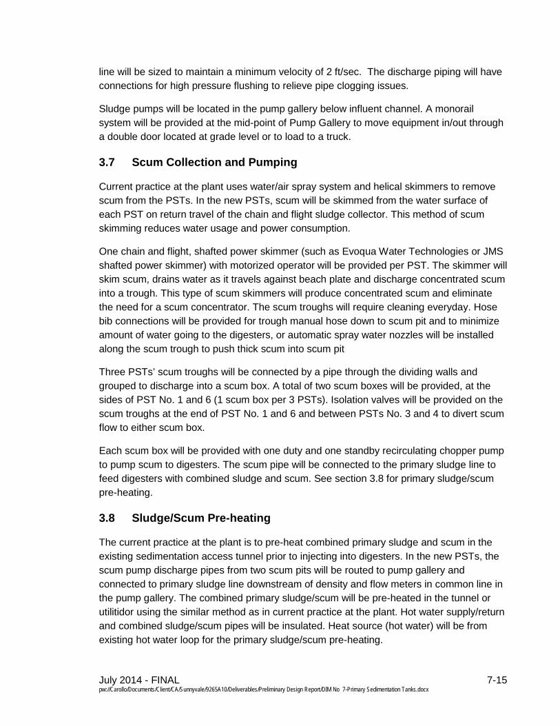
line will be sized to maintain a minimum velocity of 2 ft/sec. The discharge piping will have connections for high pressure flushing to relieve pipe clogging issues.
Sludge pumps will be located in the pump gallery below influent channel. A monorail system will be provided at the mid-point of Pump Gallery to move equipment in/out through a double door located at grade level or to load to a truck.
Scum Collection and Pumping 3.7
Current practice at the plant uses water/air spray system and helical skimmers to remove scum from the PSTs. In the new PSTs, scum will be skimmed from the water surface of each PST on return travel of the chain and flight sludge collector. This method of scum skimming reduces water usage and power consumption.
One chain and flight, shafted power skimmer (such as Evoqua Water Technologies or JMS shafted power skimmer) with motorized operator will be provided per PST. The skimmer will skim scum, drains water as it travels against beach plate and discharge concentrated scum into a trough. This type of scum skimmers will produce concentrated scum and eliminate the need for a scum concentrator. The scum troughs will require cleaning everyday. Hose bib connections will be provided for trough manual hose down to scum pit and to minimize amount of water going to the digesters, or automatic spray water nozzles will be installed along the scum trough to push thick scum into scum pit
Three PSTs’ scum troughs will be connected by a pipe through the dividing walls and grouped to discharge into a scum box. A total of two scum boxes will be provided, at the sides of PST No. 1 and 6 (1 scum box per 3 PSTs). Isolation valves will be provided on the scum troughs at the end of PST No. 1 and 6 and between PSTs No. 3 and 4 to divert scum flow to either scum box.
Each scum box will be provided with one duty and one standby recirculating chopper pump to pump scum to digesters. The scum pipe will be connected to the primary sludge line to feed digesters with combined sludge and scum. See section 3.8 for primary sludge/scum pre-heating.
Sludge/Scum Pre-heating 3.8
The current practice at the plant is to pre-heat combined primary sludge and scum in the existing sedimentation access tunnel prior to injecting into digesters. In the new PSTs, the scum pump discharge pipes from two scum pits will be routed to pump gallery and connected to primary sludge line downstream of density and flow meters in common line in the pump gallery. The combined primary sludge/scum will be pre-heated in the tunnel or utilitidor using the similar method as in current practice at the plant. Hot water supply/return and combined sludge/scum pipes will be insulated. Heat source (hot water) will be from existing hot water loop for the primary sludge/scum pre-heating.
July 2014 - FINAL 7-16 pw://Carollo/Documents/Client/CA/Sunnyvale/9265A10/Deliverables/Preliminary Design Report/DIM No 7-Primary Sedimentation Tanks.docx
Chemically Enhanced Primary Treatment
The new PSTs will have provisions to operate with CEPT under MM or higher flows when one tank is out of service to increase settling velocity of solids. The CEPT facilities will be sized to dose 20 mg/L of ferric chloride and 0.2 mg/L of polymer. In addition, the following potential CEPT future operating scenarios were identified:
• In 2023, if split treatment is implemented, two aeration basins will be constructed. If one basin needs to be taken out of service, CEPT will be likely operated during that time up to a duration of 1 to 2 months or longer as needed.
• If phosphorus removal is implemented, CEPT will be likely operated at all time. This will occur in the 2035 time frame.
• If UV is implemented in the future (2030 – 2035) iron based coagulant may need to be replaced with alum based coagulants.
• If UV and phosphorous removal are implemented in the future (2030 – 2035) iron based coagulant may need to be replaced with alum based coagulants.
CFD modeling was performed under the Master Planning Phase and incorporated into the recommendations of the Primary Sedimentation Tank TM. It assumed that the PSTs will be operated without CEPT under normal operation and the sludge protector canopy location was modeled and located accordingly. Since PSTs may be operated with CEPT (iron based coagulant) for an extended period of time in the future, the sludge protector canopy will be raised in current design to accommodate additional sludge volume caused by the CEPT chemical addition to the sludge. The sludge hopper design will not change due to extended CEPT operation. Programming of sludge pumps will be modified in the future under full time CEPT use to have run times longer than under the current limited CEPT use.
Generally alum based coagulant requires two to three times the dosage of iron based coagulant and the sludge production will change accordingly. No modifications will be required to the PSTs or sludge hoppers if ferric chloride is replaced with alum in the future for CEPT. However, alum will produce more sludge. Programming of sludge pumps will be modified in the future under full time CEPT use to run longer than under the current limited CEPT use.
The CEPT facilities and their operation are presented in DIM No. 8 Chemically Enhanced Primary Treatment, July 2014).
4.0 ELECTRICAL REQUIREMENTS In general, the electrical design for the new headworks and primary treatment facilities will comply with local, state, and federal requirements. Electrical equipment and wiring methods will be in accordance with NFPA 70, National Electric Code. Areas in and around the
July 2014 - FINAL 7-17 pw://Carollo/Documents/Client/CA/Sunnyvale/9265A10/Deliverables/Preliminary Design Report/DIM No 7-Primary Sedimentation Tanks.docx
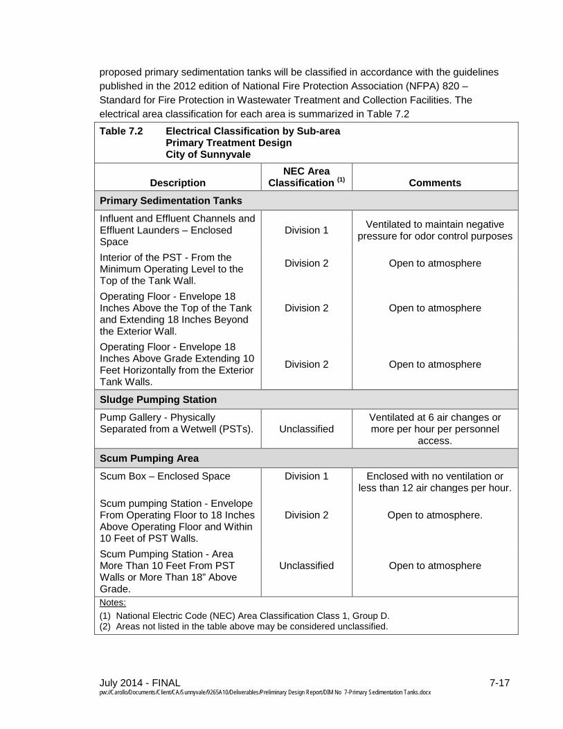
proposed primary sedimentation tanks will be classified in accordance with the guidelines published in the 2012 edition of National Fire Protection Association (NFPA) 820 – Standard for Fire Protection in Wastewater Treatment and Collection Facilities. The electrical area classification for each area is summarized in Table 7.2
Table 7.2 Electrical Classification by Sub-area Primary Treatment Design City of Sunnyvale
Description NEC Area
Classification (1) Comments
Primary Sedimentation Tanks
Influent and Effluent Channels and Effluent Launders – Enclosed Space
Division 1 Ventilated to maintain negative pressure for odor control purposes
Interior of the PST - From the Minimum Operating Level to the Top of the Tank Wall.
Division 2
Open to atmosphere
Operating Floor - Envelope 18 Inches Above the Top of the Tank and Extending 18 Inches Beyond the Exterior Wall.
Division 2
Open to atmosphere
Operating Floor - Envelope 18 Inches Above Grade Extending 10 Feet Horizontally from the Exterior Tank Walls.
Division 2 Open to atmosphere
Sludge Pumping Station
Pump Gallery - Physically Separated from a Wetwell (PSTs). Unclassified
Ventilated at 6 air changes or more per hour per personnel
access.
Scum Pumping Area
Scum Box – Enclosed Space
Division 1
Enclosed with no ventilation or less than 12 air changes per hour.
Scum pumping Station - Envelope From Operating Floor to 18 Inches Above Operating Floor and Within 10 Feet of PST Walls.
Division 2
Open to atmosphere.
Scum Pumping Station - Area More Than 10 Feet From PST Walls or More Than 18” Above Grade.
Unclassified
Open to atmosphere
Notes: (1) National Electric Code (NEC) Area Classification Class 1, Group D. (2) Areas not listed in the table above may be considered unclassified.
July 2014 - FINAL 7-18 pw://Carollo/Documents/Client/CA/Sunnyvale/9265A10/Deliverables/Preliminary Design Report/DIM No 7-Primary Sedimentation Tanks.docx
The primary sedimentation tanks will be classified as a Class 1, Division 2, Group D hazardous location for an envelope that extends 18 inches above operating level and 18 inches above grade for the area that extends 10 feet out from the tank walls. The sludge collector drive, scum skimmer drive and scum pumps fall within this area and will have motors rated for Class 1, Division 2 location. The sludge collector and scum skimmer drives will be provided with a vendor control panel (VCP) that contains power and control devices including a variable frequency drive (VFD), programmable logic controller (PLC) and local control devices. The scum pumps will be provided local control panels for manual on/off switch. These panels will be a NEMA 4X enclosure locally located at respective drive locations and will be powered from MCC located in the Headworks Electrical Building. A duct-bank (approximately 42-inch wide and 36-inch deep) will convey electrical conduits from the Electrical Buildings to the PSTs. See DIM No. 10 Power Supply and Standby Power dated July 2014 for Electrical Design. The motor starters for the sludge collectors, scum skimmer and pumps will be located in the MCC.
The sludge pumps will be located in a gallery ventilated at 6 air changes per hour or more so the motors will be rated for an unclassified location. The pumps are expected to run at constant speed, so the motor starters will be in the MCC.
5.0 CONTROL PHILOSOPHY OVERVIEW This section provides general control concepts for the proposed PSTs. Specific detailed controls for each part of the PST system will be determined during development of detailed control descriptions and process and instrumentation diagrams (P&IDs) during final design.
Local and remote control capabilities will be provided for major process equipment. Manual controls will be provided both locally, at the equipment, and remotely. Most of the major process equipment will also be provided with automatic controls.
Influent Channel 5.1
Stop plate guides provided in influent channel will allow portion of the influent channel to be taken out of service for maintenance and cleaning at a time. This also allows access to air diffusers for repair and replacement.
PST Influent Gates 5.2
The gates feeding each PST are motor actuated for convenience, but are manually opened or closed to place a PST on line or off line. Influent gates will be serviced or replaced by inserting stop plate into guides provided and isolating the PST.
July 2014 - FINAL 7-19 pw://Carollo/Documents/Client/CA/Sunnyvale/9265A10/Deliverables/Preliminary Design Report/DIM No 7-Primary Sedimentation Tanks.docx
Pre-aeration Blowers 5.3
The pre-aeration blowers consist of one duty and one standby blower. The operator will be able to select the duty blower and when operated in automatic mode, the blower will run continuously to deliver at constant air flow.
Tank Effluent Channel Gates 5.4
The effluent channel discharge gates will have motor actuators for convenience, but will not be automated and should be opened or closed by plant staff to place a PST on line or take a PST off line.
Sludge Collector Drive 5.5
A chain and flight type sludge and scum skimming (return travel) collector is provided for each PST and they normally operate continuously. Each collector is driven by an electric motor through a gear reduction drive. The gear reducer includes torque sensing switches for high torque (alarm) and high-high torque (for drive shutdown).
The sludge collector drive is started and stopped manually and normally runs continuously when a PST is online. An alarm is generated on high torque and the drive is shutdown and alarmed on high-high torque. Shutdown on high-high torque requires manual reset and manual restart of the drive.
Effluent Channel Gates 5.6
Two 66 inch primary effluent pipes are connected to effluent channel: one will convey flow to the oxidation ponds under Phase 1 and the other one is blind flanged for future connection under future work. These two pipes are provided with isolation gates to divert the flow as needed and to facilitate future operations. The gates isolating the effluent pipes will be motor actuated. Stop plate guides are provided to isolate portion of effluent channel to repair/replace primary effluent pipe isolation gates.
Primary Sludge Pumping 5.7
A duty sludge pump is provided for each PST with each pair of PST’s having a shared standby pump; 9 pumps total. The PSTs are designed for sludge thickening in the sludge hoppers therefore the system is designed to pump thickened sludge to the digesters with no provision for thin sludge pumping. Each pump is capable of manual or automatic operation. In manual the pump can be started and stopped manually and locally. In automatic, the pump will be operated on an adjustable time cycle under control from the PLC. Typically, the pump will operate 4 to 10 minutes every hour from one PST. When in automatic, an alarm will be generated if a pump fails to start or stop when called. The shared standby pump will be placed on line manually if needed and will be capable of the same manual or automatic operation as the duty pump.
July 2014 - FINAL 7-20 pw://Carollo/Documents/Client/CA/Sunnyvale/9265A10/Deliverables/Preliminary Design Report/DIM No 7-Primary Sedimentation Tanks.docx
Operating pumps will be monitored for high stator temperature and for high discharge pressure in all modes of operation. Either condition will stop the pump and initiate an alarm. These shutdowns require manual reset before the pump can be restarted. The pump seal water will be started and stopped automatically as the pump starts and stops.
Primary Scum Collection 5.8
Each PST has a scum pipe (ducking skimmer) with a motor drive and each group of 3 PSTs scum troughs are connected through wall pipe to discharge into one scum box. The skimmer drive is started and stopped manually and normally runs intermittently as long as any of the 3 PSTs in the group are running.
Primary Scum Pumping 5.9
Scum is collected from each group of 3 PSTs (2 groups) and is conveyed from each group to a common scum box for that group (2 scum boxes). Each scum box has 2 centrifugal (recirculating chopper) pumps (1 duty and 1 standby) for pumping scum to the digesters (4 pumps total). Each scum pump is capable of manual or automatic operation. In automatic the scum pump operation will be based on scum box level and adjustable pump start and stop levels. As the scum box level rises the duty pump will start at a preset level and will stop at a preset low level. If the duty pump fails to start the standby pump will start and an alarm will be generated. The standby pump will stop at the preset low level.
A jog push button will be at the scum box so the box level can be pumped down to a low level for wash down and cleaning. Pressing the jog push button will override the other controls to allow manual pump down of the scum box as long as the jog push button is pressed. Operating pumps will be monitored for high stator temperature and for high discharge pressure in all modes of operation. Either condition will stop the pump and initiate an alarm. These shutdowns require manual reset before the pump can be restarted.
An alarm will be generated on either high-high or low-low scum box level.
6.0 EQUIPMENT PROCUREMENT During the DIM Meeting 2 on April 17, 2014, HDR presented the Basis of Design for PSTs and discussed City standardized equipment. The City does not have any preference to particular equipment. All equipment covered under primary sedimentation tanks will be selected by competitive bidding. For PLCs, MCCs and other electrical/instrumentation equipment, please see DIM No. 10 Power Supply and Standby Power (July 2014) and DIM No. 11 SCADA and Facility Automation (July 2014).
July 2014 - FINAL 7-21 pw://Carollo/Documents/Client/CA/Sunnyvale/9265A10/Deliverables/Preliminary Design Report/DIM No 7-Primary Sedimentation Tanks.docx
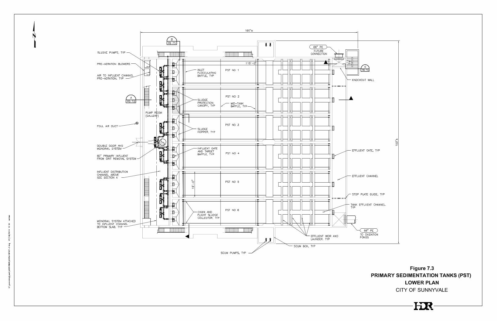
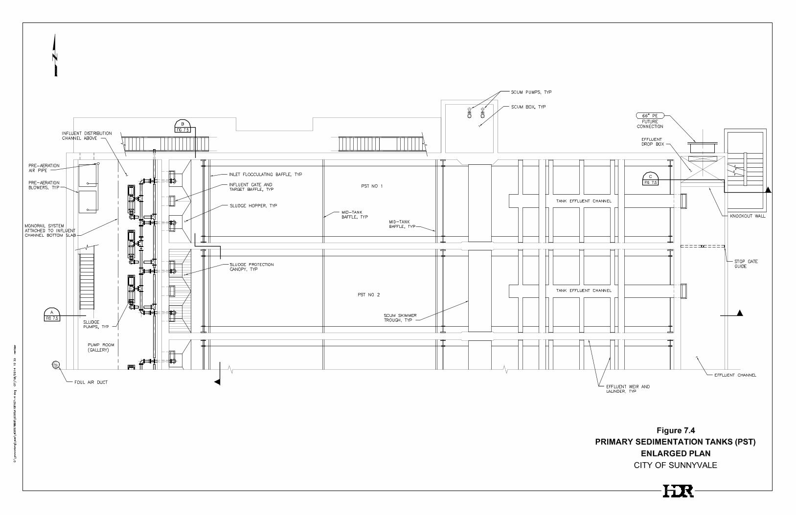
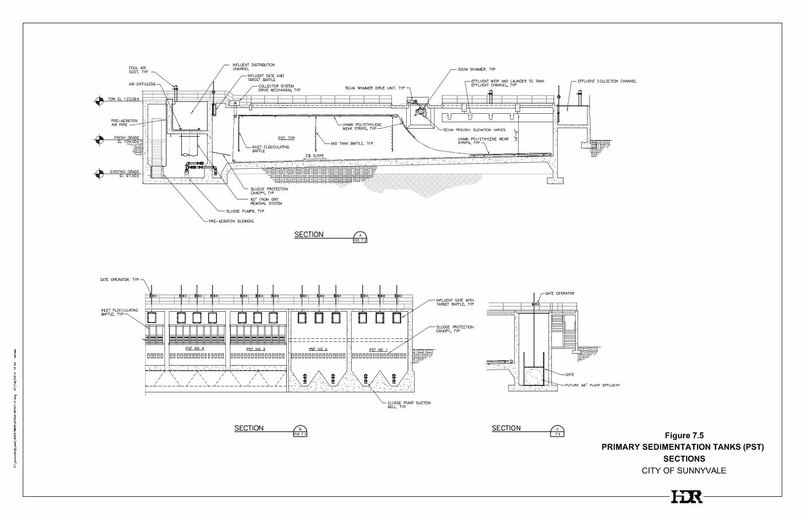
7.0 PRIMARY TREATMENT FACILITY SYSTEM LAYOUT A proposed layout for the new Primary Sedimentation Tanks is presented in Figure 7.2 and Figure 7.3. Enlarged plan of two PSTs are shown in Figure 7.4. Sectional drawings of the new PSTs are presented in Figure 7.5.
The primary sedimentation tanks floor will be located approximately 5 feet below grade at the shallow end. The tank floor will have a minimum slope of 2 percent to the sludge hopper. The operating level floor will be roughly at 12 feet above finish grade. The pump gallery will be located at the front end of PSTs and below the influent channel to accommodate sludge pumps and pre-aeration blowers. Stairways will be provided to access above and below grade operating areas.
Pump gallery and scum boxes will be enclosed and influent/effluent channels and effluent launders will be covered for odor control. The remainder of the PSTs will be open to atmosphere with provisions to cover the entire PSTs in the future for odor control if required. Walkways will be provided around the PSTs and in between PSTs at the operating floor level for operators to access gate operators and equipment drives. Guard rails will be provided on either side of walkway for fall protection.
A monorail system will be provided at the mid-point of Pump Gallery to lift and move equipment in/out through a double door at grade. A crane will be required to remove equipment from the upper deck and within the PSTs.
Site layout will be presented and further discussed at DIM Meeting 5 – Site Layout. Overall site layouts are provided in DIM No. 1 Site Layout (July 2014, Draft).
All equipment in PST area are motor driven (automatic) with manual override to gates, and require routine maintenance such as lubrication and routine inspection. Proper access and service area around the equipment will be provided to service/repair it. Sludge collector and scum skimmer drive units, gate operators, odor control fans and scum pump motors will be mounted on or above PST top deck level. If any of these equipment require replacement or off site repair, a crane will be required to move the equipment from top deck to grade level and vise versa. Equipment (sludge pumps and blowers) located in the pump gallery will be moved in and out for repair and replacement using a monorail crane. The scum pits will have roof hatches to remove scum pumps.
Front portion of PSTs will not be covered under Phase 1 construction; however provisions will be made to cover entire PSTs in future. Covered area for odor control will have sufficient amount of view ports or removable covers for operators to visually see the moving parts of equipment below the cover, effluent trough and channel, and scum skimmer and trough. If entire PSTs are covered in future, removable covers will be provided to remove equipment in the PSTs.
July 2014 - FINAL 7-22 pw://Carollo/Documents/Client/CA/Sunnyvale/9265A10/Deliverables/Preliminary Design Report/DIM No 7-Primary Sedimentation Tanks.docx
Scum trough will require daily wash-down since concentrated scum will be discharged into it and to prevent scum build-ups. Sufficient amount of utility water stations will be provided to facilitate housekeeping.
Flocculating and mid-tank baffles, sludge canopy and sludge collector will require cleaning every two years to remove build-ups. These components will be below water surface elevation and will be hard to inspect from top deck. The PSTs will be taken out of service for routine maintenance of above items, and tank drains will be provided to drain PSTs.
8.0 ANCILLARY FACILITIES
Potable Water 8.1
Potable water will not be required for the new PSTs.
Utility Water 8.2
Utility water (disinfected tertiary effluent) will be used at the plant for non-potable water needs. Utility water will be required for washdown, spray water to influent channel and scum pipes, seal water to pumps and sludge/scum line flushing purposes in the PSTs area. Hose bib connections will be provided at locations where operators can easily access for housekeeping.
Plant Air 8.3
Plant air connections will be provided at each utility water station at the Primary Sedimentation Tank Facility.
HVAC 8.4
The influent/effluent channels and effluent launders will be covered and ventilated to maintain negative pressure for odor control purposes. The pump gallery will be ventilated to provide a suitable work atmosphere, to provide sufficient air intake for blowers and for ventilation purposes. The remainder of the PSTs area will have provision to cover for odor control in the future and this will change the electrical area classification requirements. No areas in the Primary Sedimentation Tanks Facility will be ventilated with the intent of de-rating the electrical area classification.
Reference DIM No. 10, Ventilation and Odor Control, for ventilation requirements, air flow diagrams, and other HVAC criteria.


July 2014 - FINAL 7-31 pw://Carollo/Documents/Client/CA/Sunnyvale/9265A10/Deliverables/Preliminary Design Report/DIM No 7-Primary Sedimentation Tanks.docx
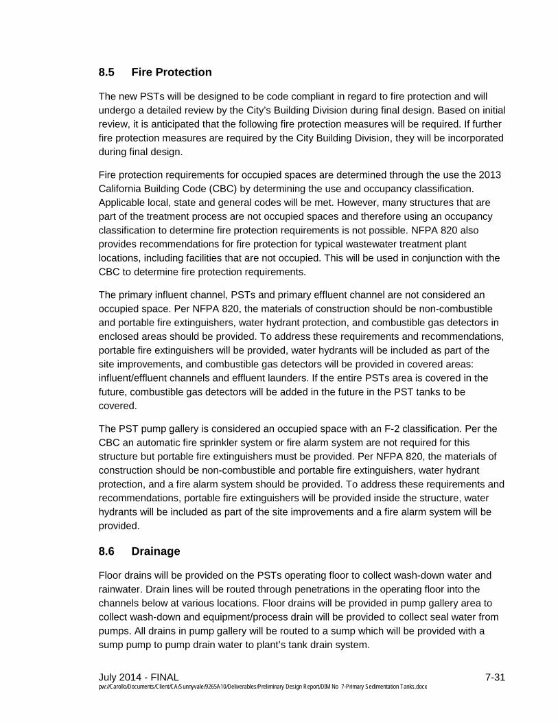
Fire Protection 8.5
The new PSTs will be designed to be code compliant in regard to fire protection and will undergo a detailed review by the City’s Building Division during final design. Based on initial review, it is anticipated that the following fire protection measures will be required. If further fire protection measures are required by the City Building Division, they will be incorporated during final design.
Fire protection requirements for occupied spaces are determined through the use the 2013 California Building Code (CBC) by determining the use and occupancy classification. Applicable local, state and general codes will be met. However, many structures that are part of the treatment process are not occupied spaces and therefore using an occupancy classification to determine fire protection requirements is not possible. NFPA 820 also provides recommendations for fire protection for typical wastewater treatment plant locations, including facilities that are not occupied. This will be used in conjunction with the CBC to determine fire protection requirements.
The primary influent channel, PSTs and primary effluent channel are not considered an occupied space. Per NFPA 820, the materials of construction should be non-combustible and portable fire extinguishers, water hydrant protection, and combustible gas detectors in enclosed areas should be provided. To address these requirements and recommendations, portable fire extinguishers will be provided, water hydrants will be included as part of the site improvements, and combustible gas detectors will be provided in covered areas: influent/effluent channels and effluent launders. If the entire PSTs area is covered in the future, combustible gas detectors will be added in the future in the PST tanks to be covered.
The PST pump gallery is considered an occupied space with an F-2 classification. Per the CBC an automatic fire sprinkler system or fire alarm system are not required for this structure but portable fire extinguishers must be provided. Per NFPA 820, the materials of construction should be non-combustible and portable fire extinguishers, water hydrant protection, and a fire alarm system should be provided. To address these requirements and recommendations, portable fire extinguishers will be provided inside the structure, water hydrants will be included as part of the site improvements and a fire alarm system will be provided.
Drainage 8.6
Floor drains will be provided on the PSTs operating floor to collect wash-down water and rainwater. Drain lines will be routed through penetrations in the operating floor into the channels below at various locations. Floor drains will be provided in pump gallery area to collect wash-down and equipment/process drain will be provided to collect seal water from pumps. All drains in pump gallery will be routed to a sump which will be provided with a sump pump to pump drain water to plant’s tank drain system.
July 2014 - FINAL 7-32 pw://Carollo/Documents/Client/CA/Sunnyvale/9265A10/Deliverables/Preliminary Design Report/DIM No 7-Primary Sedimentation Tanks.docx
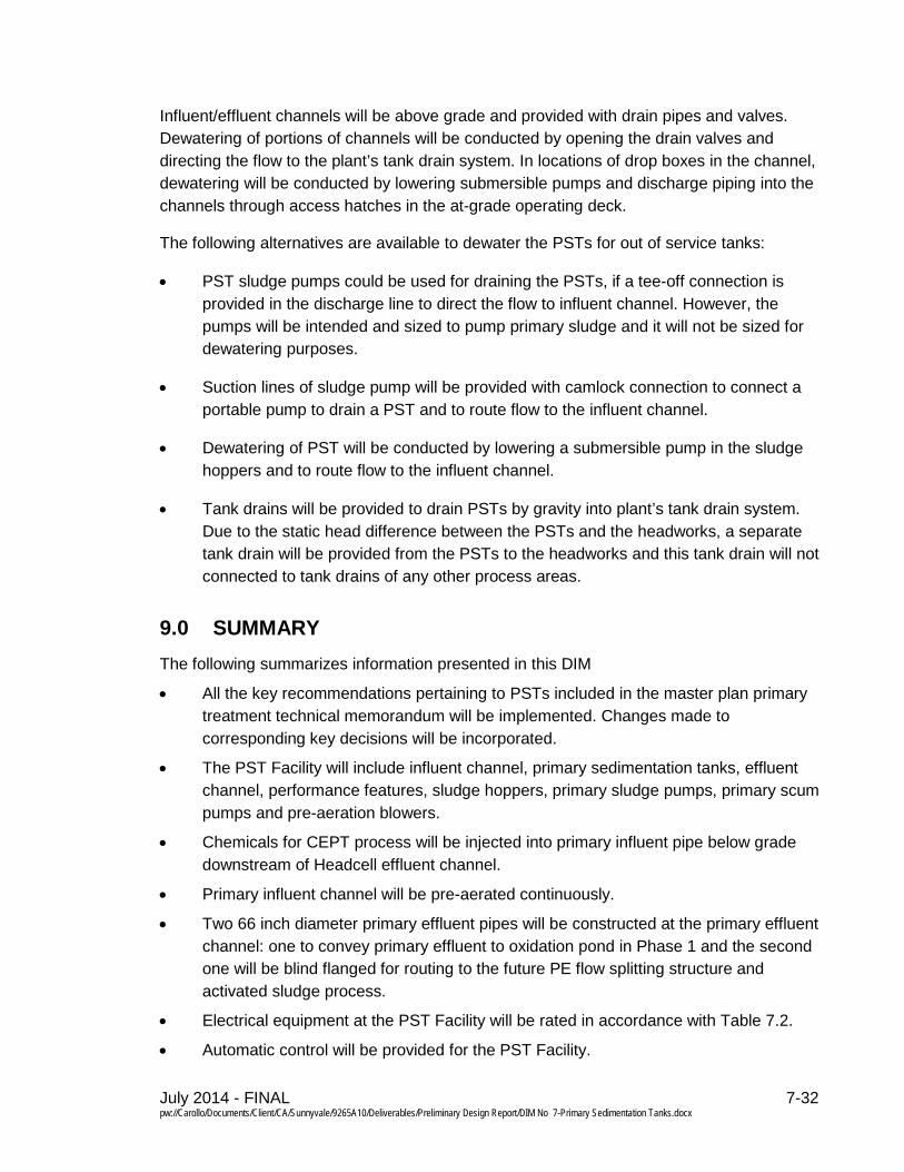
Influent/effluent channels will be above grade and provided with drain pipes and valves. Dewatering of portions of channels will be conducted by opening the drain valves and directing the flow to the plant’s tank drain system. In locations of drop boxes in the channel, dewatering will be conducted by lowering submersible pumps and discharge piping into the channels through access hatches in the at-grade operating deck.
The following alternatives are available to dewater the PSTs for out of service tanks:
• PST sludge pumps could be used for draining the PSTs, if a tee-off connection is provided in the discharge line to direct the flow to influent channel. However, the pumps will be intended and sized to pump primary sludge and it will not be sized for dewatering purposes.
• Suction lines of sludge pump will be provided with camlock connection to connect a portable pump to drain a PST and to route flow to the influent channel.
• Dewatering of PST will be conducted by lowering a submersible pump in the sludge hoppers and to route flow to the influent channel.
• Tank drains will be provided to drain PSTs by gravity into plant’s tank drain system. Due to the static head difference between the PSTs and the headworks, a separate tank drain will be provided from the PSTs to the headworks and this tank drain will not connected to tank drains of any other process areas.
9.0 SUMMARY The following summarizes information presented in this DIM
• All the key recommendations pertaining to PSTs included in the master plan primary treatment technical memorandum will be implemented. Changes made to corresponding key decisions will be incorporated.
• The PST Facility will include influent channel, primary sedimentation tanks, effluent channel, performance features, sludge hoppers, primary sludge pumps, primary scum pumps and pre-aeration blowers.
• Chemicals for CEPT process will be injected into primary influent pipe below grade downstream of Headcell effluent channel.
• Primary influent channel will be pre-aerated continuously.
• Two 66 inch diameter primary effluent pipes will be constructed at the primary effluent channel: one to convey primary effluent to oxidation pond in Phase 1 and the second one will be blind flanged for routing to the future PE flow splitting structure and activated sludge process.
• Electrical equipment at the PST Facility will be rated in accordance with Table 7.2.
• Automatic control will be provided for the PST Facility.
July 2014 - FINAL 7-33 pw://Carollo/Documents/Client/CA/Sunnyvale/9265A10/Deliverables/Preliminary Design Report/DIM No 7-Primary Sedimentation Tanks.docx
• Primary influent/effluent channels and launders will be covered for odor control. Provisions will be provided to cover entire PST area for odor control in the future.
• It is anticipated that automatic fire sprinkler systems would not to be required in the pump gallery, subject to review by the City’s Building Division. Water hydrant protection, portable fire extinguishers, and combustible gas detectors will be provided at the PST Facility. Water hydrant protection, portable fire extinguishers, and a fire alarm system will be provided at the pump gallery.

July 2014 - FINAL pw://Carollo/Documents/Client/CA/Sunnyvale/9265A10/Deliverables/Preliminary Design Report/DIM No 7-Primary Sedimentation Tanks.docx
Design Information Memorandum No. 7 APPENDIX A – EQUIPMENT DATA SHEETS AND CUT SHEETS FOR KEY PROCESS EQUIPMENT

July 2014 - FINAL pw://Carollo/Documents/Client/CA/Sunnyvale/9265A10/Deliverables/Preliminary Design Report/DIM No 7-Primary Sedimentation Tanks.docx
Design Information Memorandum No. 7 CHAIN AND FLIGHT SLUDGE COLLECTOR

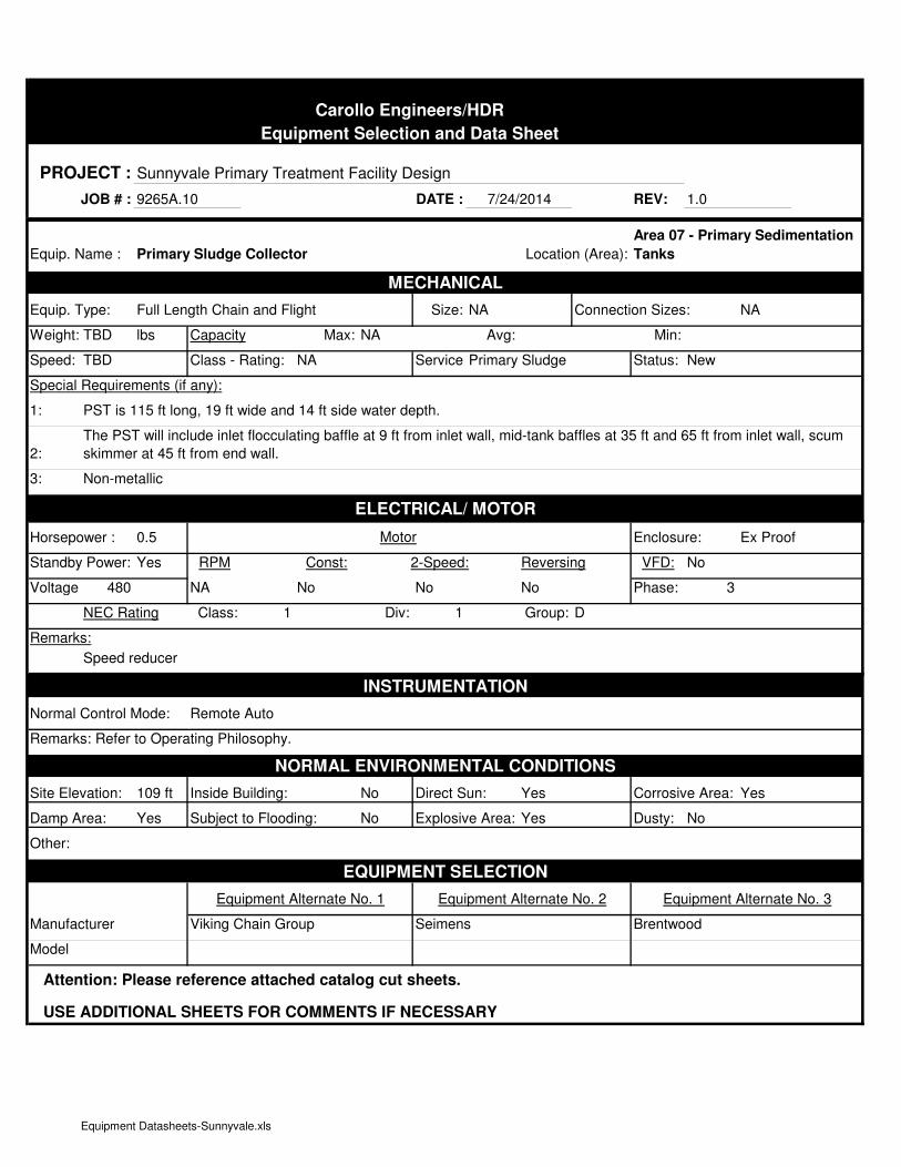
Carollo Engineers/HDR
Equipment Selection and Data Sheet
PROJECT : Sunnyvale Primary Treatment Facility Design
JOB # : 9265A.10 DATE : REV: 1.0
Equip. Name : Location (Area):
MECHANICAL
Equip. Type: Full Length Chain and Flight Size: NA Connection Sizes: NA
Weight: TBD lbs Capacity Max: NA Avg: Min:
Speed: TBD Class - Rating: NA Service:Primary Sludge Status: New
Special Requirements (if any):
1: PST is 115 ft long, 19 ft wide and 14 ft side water depth.
2:
3: Non-metallic
ELECTRICAL/ MOTOR
Horsepower : 0.5 Motor Enclosure: Ex Proof
Standby Power: Yes RPM Const: 2-Speed: Reversing VFD: No
Voltage: 480 NA No No No Phase: 3
NEC Rating Class: 1 Div: 1 Group: D
Remarks:
Speed reducer
INSTRUMENTATION
Normal Control Mode: Remote Auto
Remarks: Refer to Operating Philosophy.
NORMAL ENVIRONMENTAL CONDITIONS
Site Elevation: 109 ft Inside Building: No Direct Sun: Yes Corrosive Area: Yes
Damp Area: Yes Subject to Flooding: No Explosive Area: Yes Dusty: No
Other:
EQUIPMENT SELECTION
Equipment Alternate No. 1 Equipment Alternate No. 2 Equipment Alternate No. 3
Manufacturer Viking Chain Group Seimens Brentwood
Model
Attention: Please reference attached catalog cut sheets.
USE ADDITIONAL SHEETS FOR COMMENTS IF NECESSARY
Area 07 - Primary Sedimentation
Tanks
7/24/2014
Primary Sludge Collector
The PST will include inlet flocculating baffle at 9 ft from inlet wall, mid-tank baffles at 35 ft and 65 ft from inlet wall, scum
skimmer at 45 ft from end wall.
Equipment Datasheets-Sunnyvale.xls

www.vikingchains.com
STRONG • RELIABLE • COST EFFECTIVE
e n v i r o d i v i s i o n
DELTA, BC VANIER, PQ VANCOUVER, WA ACWORTH, GA
Four convenient locations to better serve you
VANCOUVER, WA 360-694-1416 TOLL FREE 1-866-513-4078ACWORTH, GA 678-574-0251 TOLL FREE 1-877-941-1500PAGE 2
VC720S NON-METALLIC CHAIN
e n v i r o d i v i s i o n
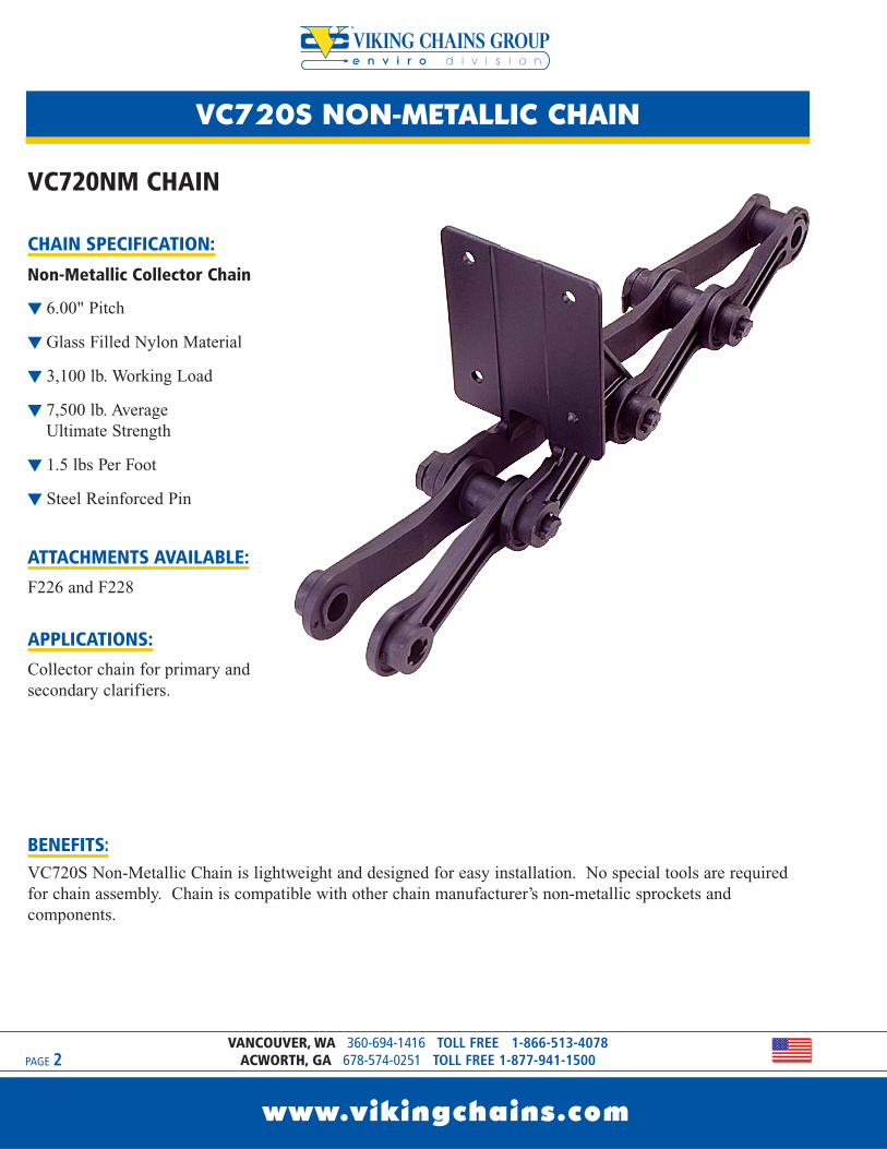
VC720NM CHAIN
CHAIN SPECIFICATION:
Non-Metallic Collector Chain
t 6.00" Pitch
t Glass Filled Nylon Material
t 3,100 lb. Working Load
t 7,500 lb. Average Ultimate Strength
t 1.5 lbs Per Foot
t Steel Reinforced Pin
ATTACHMENTS AVAILABLE:F226 and F228
APPLICATIONS:Collector chain for primary andsecondary clarifiers.
BENEFITS:VC720S Non-Metallic Chain is lightweight and designed for easy installation. No special tools are requiredfor chain assembly. Chain is compatible with other chain manufacturer’s non-metallic sprockets andcomponents.
www.vikingchains.com
VC720S NON-METALLIC CHAIN
www.vikingchains.com
PAGE 3
e n v i r o d i v i s i o n
DELTA, BC 604-952-4146 TOLL FREE 1-800-324-1244VANIER, PQ 418-650-6090 TOLL FREE 1-888-650-6090
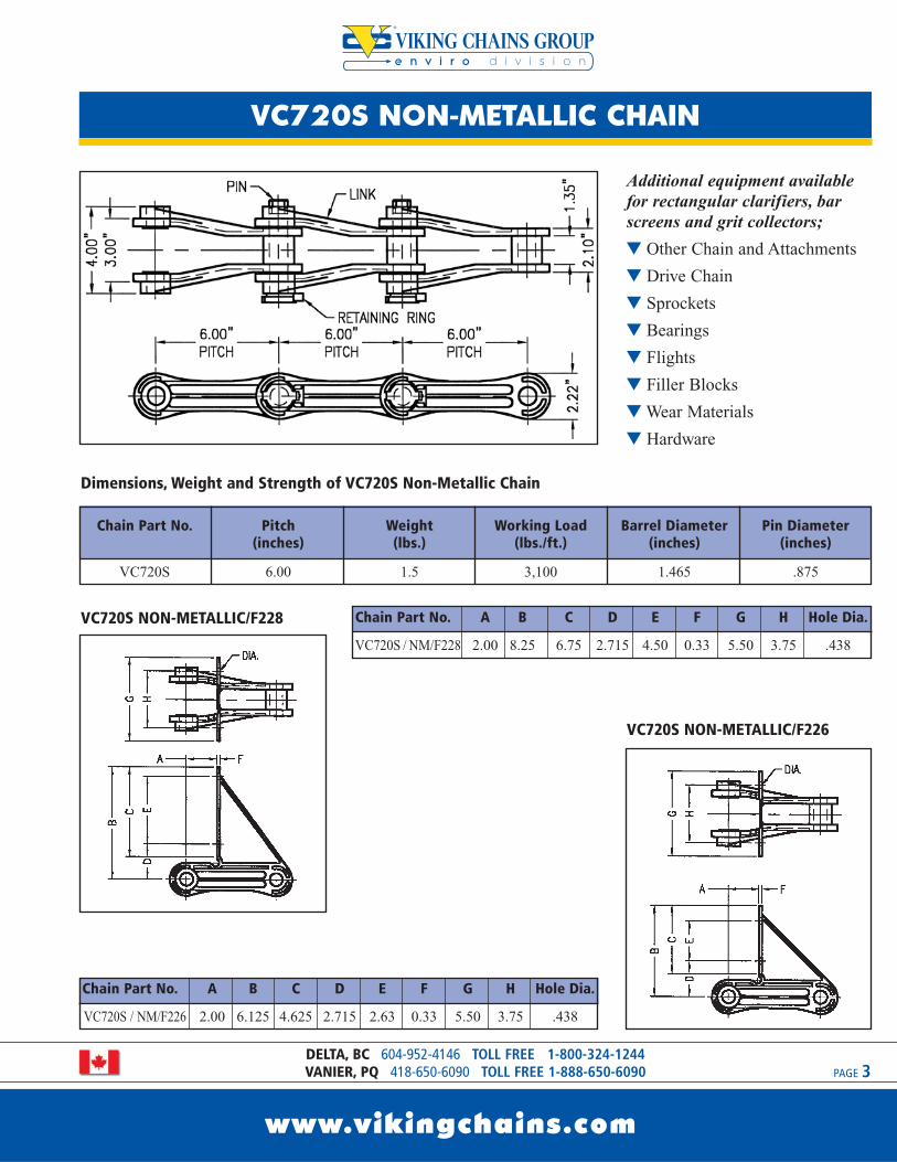
Dimensions, Weight and Strength of VC720S Non-Metallic Chain
VC720S NON-METALLIC/F228
VC720S NON-METALLIC/F226
Additional equipment availablefor rectangular clarifiers, barscreens and grit collectors;
t Other Chain and Attachments
t Drive Chain
t Sprockets
t Bearings
t Flights
t Filler Blocks
tWear Materials
t Hardware
Chain Part No. Pitch Weight Working Load Barrel Diameter Pin Diameter(inches) (lbs.) (lbs./ft.) (inches) (inches)
VC720S 6.00 1.5 3,100 1.465 .875
Chain Part No. A B C D E F G H Hole Dia.
VC720S / NM/F226 2.00 6.125 4.625 2.715 2.63 0.33 5.50 3.75 .438
Chain Part No. A B C D E F G H Hole Dia.
VC720S / NM/F228 2.00 8.25 6.75 2.715 4.50 0.33 5.50 3.75 .438
e n v i r o d i v i s i o n
VC/NH78 NON-METALLIC CHAIN
www.vikingchains.com
PAGE 4VANCOUVER, WA 360-694-1416 TOLL FREE 1-866-513-4078
ACWORTH, GA 678-574-0251 TOLL FREE 1-877-941-1500
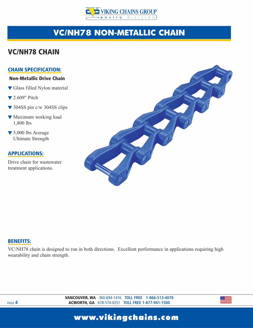
VC/NH78 CHAIN
CHAIN SPECIFICATION:
Non-Metallic Drive Chain
t Glass filled Nylon material
t 2.609" Pitch
t 304SS pin c/w 304SS clips
tMaximum working load 1,800 lbs
t 5,000 lbs Average Ultimate Strength
APPLICATIONS:Drive chain for wastewatertreatment applications.
BENEFITS:VC/NH78 chain is designed to run in both directions. Excellent performance in applications requiring highwearability and chain strength.

VC/NH78 NON-METALLIC CHAIN
www.vikingchains.com
PAGE 5
e n v i r o d i v i s i o n
DELTA, BC 604-952-4146 TOLL FREE 1-800-324-1244VANIER, PQ 418-650-6090 TOLL FREE 1-888-650-6090
Chain Part No. Weight Maximum Permissible Backflex Radius(lbs./ft.) Tensile Force (lbs.) (inches)
VC/NH78 1.41 1800 3
Dimensions, Weight and Strength of VC/NH78 Non-Metallic Chain
t Chain and Attachments
t Bearings
tWear Materials
t Other Drive Chains
t Flights
t Sprockets
t Filler Blocks
t Hardware
Additional equipment available for rectangular clarifiers, bar screens and grit collectors;

e n v i r o d i v i s i o n
VCSS700 STAINLESS STEEL CHAIN
www.vikingchains.com
PAGE 6VANCOUVER, WA 360-694-1416 TOLL FREE 1-866-513-4078
ACWORTH, GA 678-574-0251 TOLL FREE 1-877-941-1500
VCSS700 CHAIN
CHAIN SPECIFICATION:
Stainless Steel Collector Chain
t 6.00" Pitch
t 403 Grade Stainless SteelMaterial
t 33,000 lb. Average Ultimate Strength
t 3.9 lbs Per Foot
t Hardened Pins and Bushings
ATTACHMENTS AVAILABLE:F226, F228, D22, K2, A2, A42, AM116
APPLICATIONS:For use in primary and secondaryclarifiers, grit collectors, and barscreens.
BENEFITS:VCSS700 stainless steel chain is a lightweight but high strength chain designed to withstand highly corrosiveenvironments. Provides superior performance in long length clarifiers with high loads and longer chain life inhigh grit and abrasive environments. Designed to be compatible with VCSS700 series chain saver sprocketsand with other stainless steel chain manufacturer’s components. Can be used with either fiberglass, laminatedwood or aluminum flights.
VCSS700 STAINLESS STEEL CHAIN
www.vikingchains.com
PAGE 7
e n v i r o d i v i s i o n
DELTA, BC 604-952-4146 TOLL FREE 1-800-324-1244VANIER, PQ 418-650-6090 TOLL FREE 1-888-650-6090
VCSS700/F228
VCSS700/F226
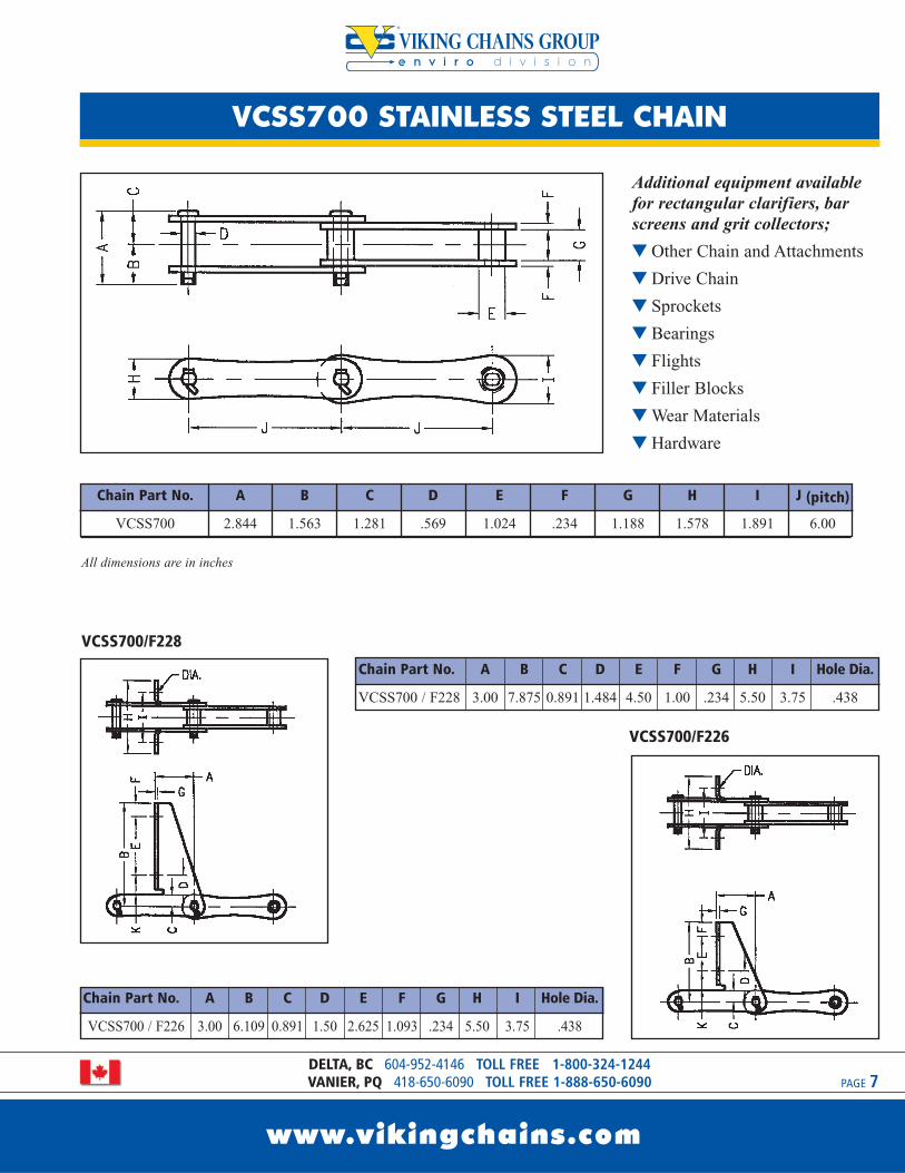
Chain Part No. A B C D E F G H I Hole Dia.
VCSS700 / F228 3.00 7.875 0.891 1.484 4.50 1.00 .234 5.50 3.75 .438
Additional equipment availablefor rectangular clarifiers, barscreens and grit collectors;
t Other Chain and Attachments
t Drive Chain
t Sprockets
t Bearings
t Flights
t Filler Blocks
tWear Materials
t Hardware
Chain Part No. A B C D E F G H I J (pitch)
VCSS700 2.844 1.563 1.281 .569 1.024 .234 1.188 1.578 1.891 6.00
All dimensions are in inches
Chain Part No. A B C D E F G H I Hole Dia.
VCSS700 / F226 3.00 6.109 0.891 1.50 2.625 1.093 .234 5.50 3.75 .438
e n v i r o d i v i s i o n
VCSS701 STAINLESS STEEL CHAIN
www.vikingchains.com
PAGE 8VANCOUVER, WA 360-694-1416 TOLL FREE 1-866-513-4078
ACWORTH, GA 678-574-0251 TOLL FREE 1-877-941-1500
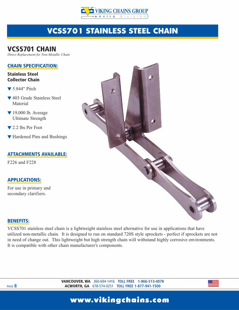
VCSS701 CHAINDirect Replacement for Non-Metallic Chain
CHAIN SPECIFICATION:
Stainless Steel Collector Chain
t 5.844" Pitch
t 403 Grade Stainless SteelMaterial
t 19,000 lb. Average Ultimate Strength
t 2.2 lbs Per Foot
t Hardened Pins and Bushings
ATTACHMENTS AVAILABLE:F226 and F228
APPLICATIONS:For use in primary andsecondary clarifiers.
BENEFITS:VCSS701 stainless steel chain is a lightweight stainless steel alternative for use in applications that haveutilized non-metallic chain. It is designed to run on standard 720S style sprockets - perfect if sprockets are notin need of change out. This lightweight but high strength chain will withstand highly corrosive environments.It is compatible with other chain manufacturer’s components.
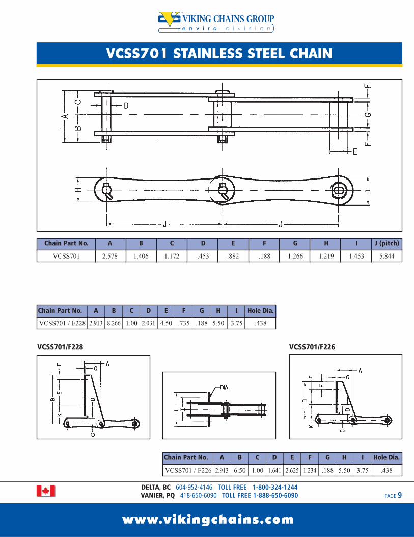
Chain Part No. A B C D E F G H I J (pitch)
VCSS701 2.578 1.406 1.172 .453 .882 .188 1.266 1.219 1.453 5.844
VCSS701 STAINLESS STEEL CHAIN
www.vikingchains.com
PAGE 9
e n v i r o d i v i s i o n
DELTA, BC 604-952-4146 TOLL FREE 1-800-324-1244VANIER, PQ 418-650-6090 TOLL FREE 1-888-650-6090
VCSS701/F226VCSS701/F228
Chain Part No. A B C D E F G H I Hole Dia.
VCSS701 / F228 2.913 8.266 1.00 2.031 4.50 .735 .188 5.50 3.75 .438
Chain Part No. A B C D E F G H I Hole Dia.
VCSS701 / F226 2.913 6.50 1.00 1.641 2.625 1.234 .188 5.50 3.75 .438
e n v i r o d i v i s i o n
VCSS78 STAINLESS STEEL CHAIN
www.vikingchains.com
PAGE 10VANCOUVER, WA 360-694-1416 TOLL FREE 1-866-513-4078
ACWORTH, GA 678-574-0251 TOLL FREE 1-877-941-1500
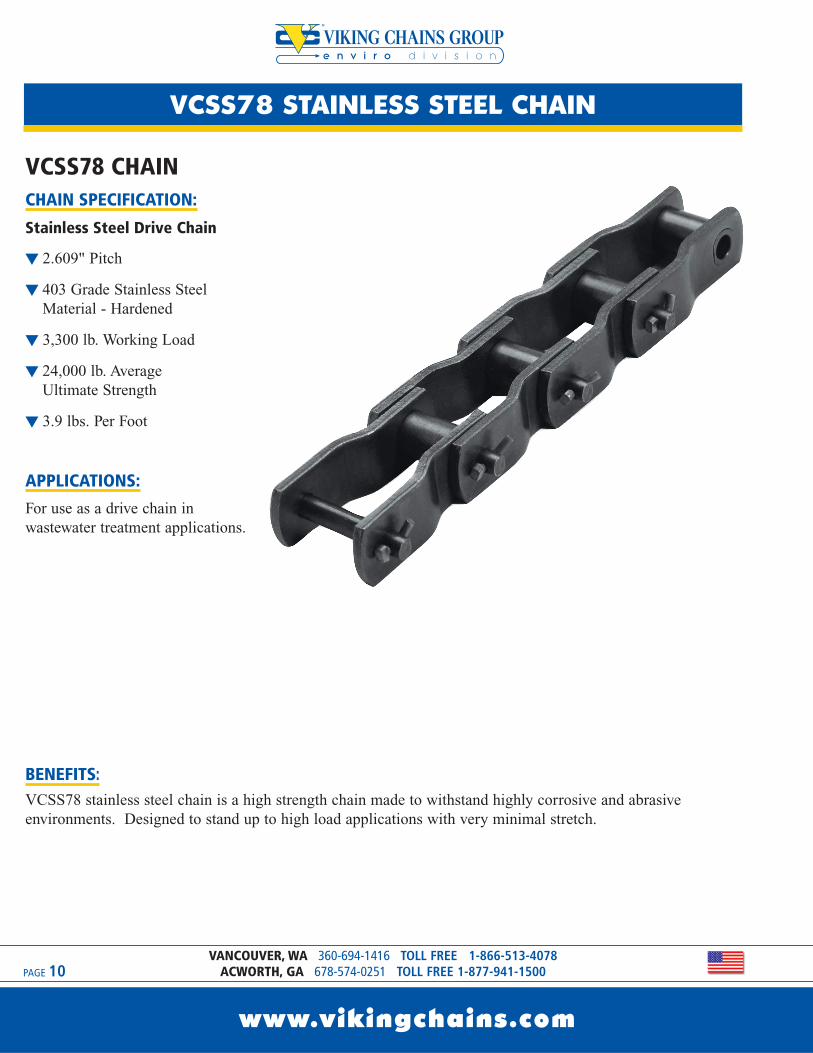
VCSS78 CHAINCHAIN SPECIFICATION:
Stainless Steel Drive Chain
t 2.609" Pitch
t 403 Grade Stainless SteelMaterial - Hardened
t 3,300 lb. Working Load
t 24,000 lb. Average Ultimate Strength
t 3.9 lbs. Per Foot
APPLICATIONS:For use as a drive chain inwastewater treatment applications.
BENEFITS:VCSS78 stainless steel chain is a high strength chain made to withstand highly corrosive and abrasiveenvironments. Designed to stand up to high load applications with very minimal stretch.
VCSS78 STAINLESS STEEL CHAIN
www.vikingchains.com
PAGE 11
e n v i r o d i v i s i o n
DELTA, BC 604-952-4146 TOLL FREE 1-800-324-1244VANIER, PQ 418-650-6090 TOLL FREE 1-888-650-6090
Additional equipmentavailable for rectangularclarifiers, bar screens and gritcollectors;
t Chain and Attachments
t Other Drive Chains
t Sprockets
t Bearings
t Flights
t Filler Blocks
tWear Materials
t Hardware
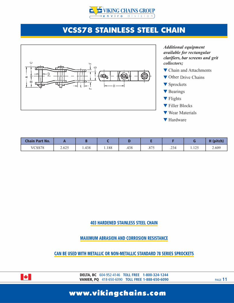
403 HARDENED STAINLESS STEEL CHAIN
MAXIMUM ABRASION AND CORROSION RESISTANCE
CAN BE USED WITH METALLIC OR NON-METALLIC STANDARD 78 SERIES SPROCKETS
Chain Part No. A B C D E F G H (pitch)
VCSS78 2.625 1.438 1.188 .438 .875 .234 1.125 2.609
www.vikingchains.com
PAGE 12VANCOUVER, WA 360-694-1416 TOLL FREE 1-866-513-4078
ACWORTH, GA 678-574-0251 TOLL FREE 1-877-941-1500
STRONG
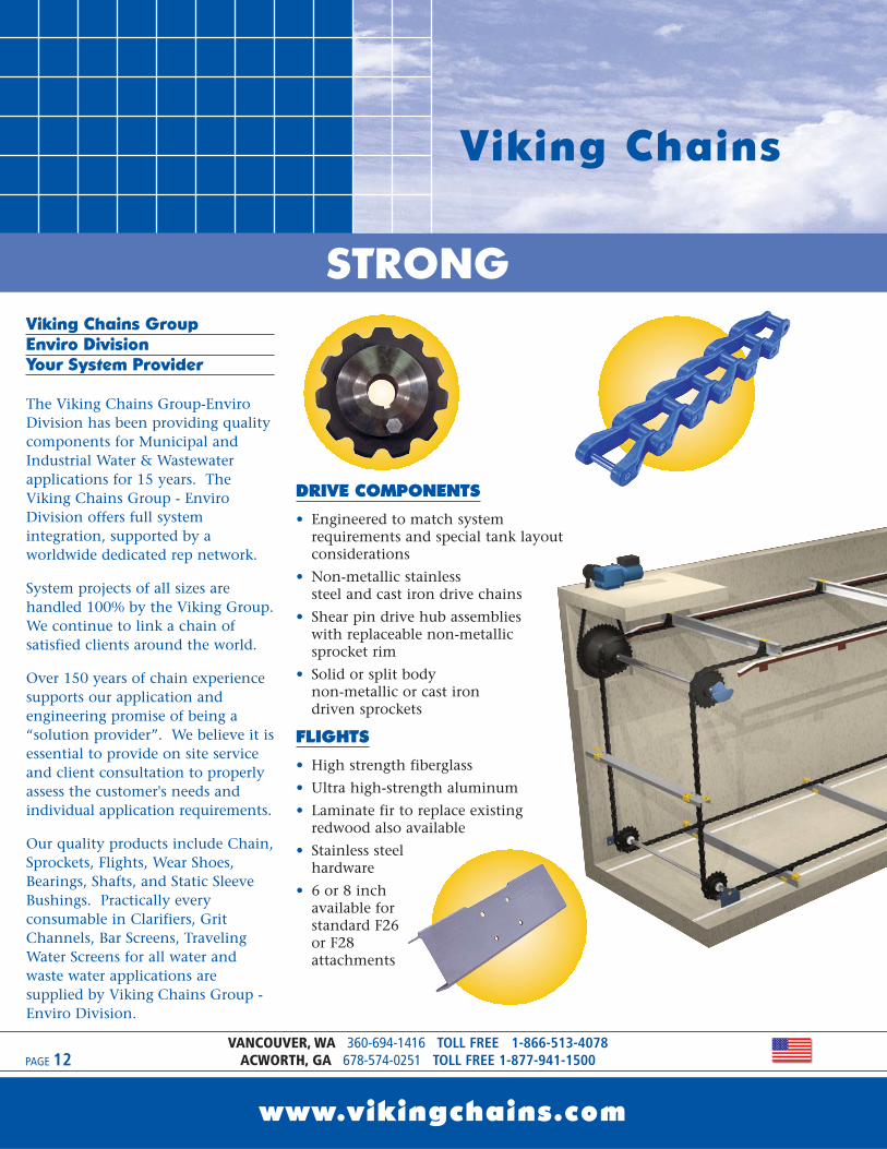
Viking Chains
Viking Chains GroupEnviro DivisionYour System Provider
The Viking Chains Group-EnviroDivision has been providing qualitycomponents for Municipal andIndustrial Water & Wastewaterapplications for 15 years. TheViking Chains Group - EnviroDivision offers full systemintegration, supported by aworldwide dedicated rep network.
System projects of all sizes arehandled 100% by the Viking Group.We continue to link a chain ofsatisfied clients around the world.
Over 150 years of chain experiencesupports our application andengineering promise of being a“solution provider”. We believe it isessential to provide on site serviceand client consultation to properlyassess the customer's needs andindividual application requirements.
Our quality products include Chain,Sprockets, Flights, Wear Shoes,Bearings, Shafts, and Static SleeveBushings. Practically everyconsumable in Clarifiers, GritChannels, Bar Screens, TravelingWater Screens for all water andwaste water applications aresupplied by Viking Chains Group -Enviro Division.
DRIVE COMPONENTS
• Engineered to match systemrequirements and special tank layoutconsiderations
• Non-metallic stainless steel and cast iron drive chains
• Shear pin drive hub assemblies with replaceable non-metallicsprocket rim
• Solid or split body non-metallic or cast iron driven sprockets
FLIGHTS
• High strength fiberglass• Ultra high-strength aluminum• Laminate fir to replace existing
redwood also available• Stainless steel
hardware• 6 or 8 inch
available forstandard F26 or F28attachments
www.vikingchains.com
PAGE 13DELTA, BC 604-952-4146 TOLL FREE 1-800-324-1244VANIER, PQ 418-650-6090 TOLL FREE 1-888-650-6090
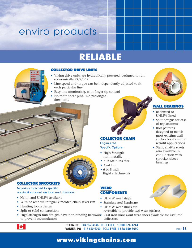
RELIABLE
enviro products
WALL BEARINGS• Babbitted or
UHMW lined• Split designs for ease
of replacement• Bolt patterns
designed to matchmost existing wallanchor locations forretrofit applications
• Static shaftbracketsalso available inconjunction withsprocket sleevebearings
COLLECTOR CHAINEngineered Specific Options:
• High Strength non-metallic
• 403 Stainless Steel• Cast Iron• 6 or 8 inch
flight attachments
COLLECTOR SPROCKETSMaterials matched to specificapplication based on load and abrasion:
• Nylon and UHMW available• With or without integrally molded chain saver rim• Hunting tooth design• Split or solid construction• High-strength hub designs have non-binding hardware
to prevent accumulation
WEAR COMPONENTS• UHMW wear strips• Stainless steel hardware• UHMW wear shoes are
reversible to provide two wear surfaces• Cast iron knock-out wear shoes available for cast iron
collectors
COLLECTOR DRIVE UNITS• Viking drive units are hydraulically powered, designed to run
economically 24/7/365• Line speed and torque can be independently adjusted to fit
each particular line• Easy line monitoring, with finger tip control• No more shear pins. No prolonged
downtime
e n v i r o d i v i s i o n
VC CAST IRON CHAIN
www.vikingchains.com
PAGE 14VANCOUVER, WA 360-694-1416 TOLL FREE 1-866-513-4078
ACWORTH, GA 678-574-0251 TOLL FREE 1-877-941-1500
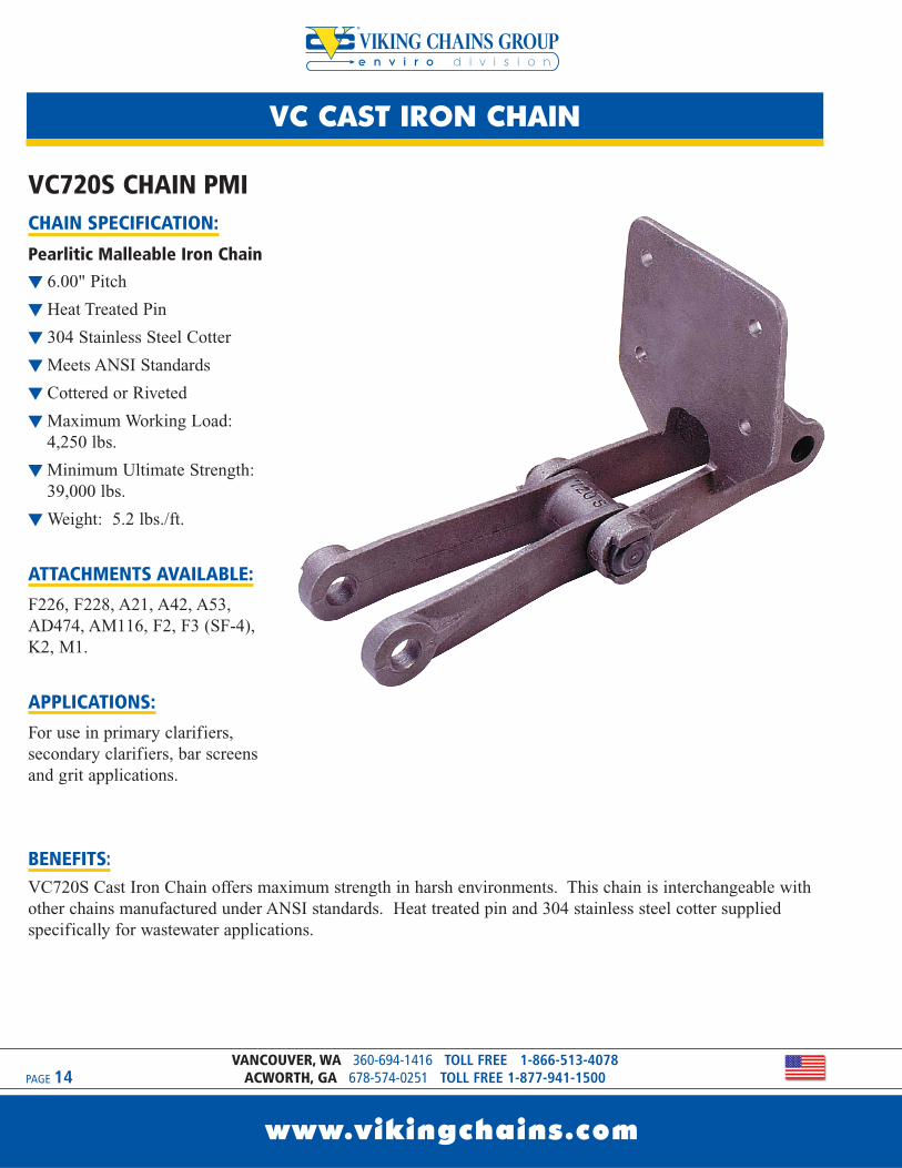
VC720S CHAIN PMICHAIN SPECIFICATION:
Pearlitic Malleable Iron Chain
t 6.00" Pitch
t Heat Treated Pin
t 304 Stainless Steel Cotter
tMeets ANSI Standards
t Cottered or Riveted
tMaximum Working Load:4,250 lbs.
tMinimum Ultimate Strength:39,000 lbs.
tWeight: 5.2 lbs./ft.
ATTACHMENTS AVAILABLE:F226, F228, A21, A42, A53,AD474, AM116, F2, F3 (SF-4),K2, M1.
APPLICATIONS:For use in primary clarifiers,secondary clarifiers, bar screensand grit applications.
BENEFITS:VC720S Cast Iron Chain offers maximum strength in harsh environments. This chain is interchangeable withother chains manufactured under ANSI standards. Heat treated pin and 304 stainless steel cotter suppliedspecifically for wastewater applications.
VC CAST IRON CHAIN
www.vikingchains.com
PAGE 15
e n v i r o d i v i s i o n
DELTA, BC 604-952-4146 TOLL FREE 1-800-324-1244VANIER, PQ 418-650-6090 TOLL FREE 1-888-650-6090
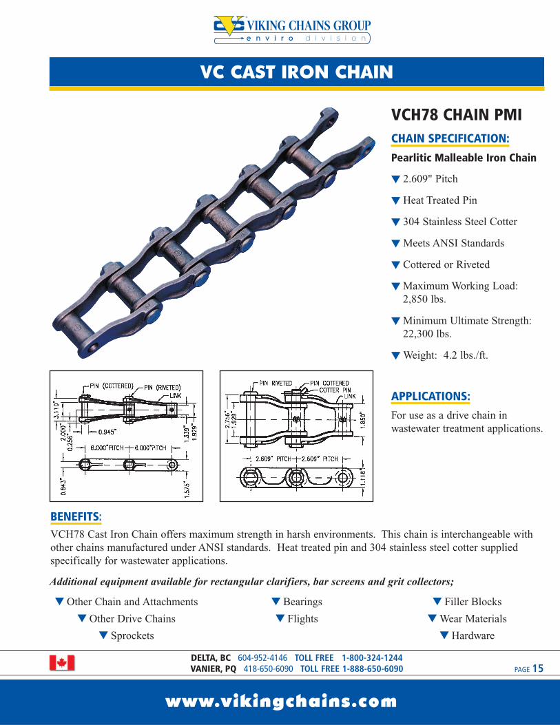
VCH78 CHAIN PMICHAIN SPECIFICATION:
Pearlitic Malleable Iron Chain
t 2.609" Pitch
t Heat Treated Pin
t 304 Stainless Steel Cotter
tMeets ANSI Standards
t Cottered or Riveted
tMaximum Working Load:2,850 lbs.
tMinimum Ultimate Strength:22,300 lbs.
tWeight: 4.2 lbs./ft.
APPLICATIONS:For use as a drive chain inwastewater treatment applications.
BENEFITS:VCH78 Cast Iron Chain offers maximum strength in harsh environments. This chain is interchangeable withother chains manufactured under ANSI standards. Heat treated pin and 304 stainless steel cotter suppliedspecifically for wastewater applications.
t Other Chain and Attachments
t Other Drive Chains
t Sprockets
t Bearings
t Flights
t Filler Blocks
tWear Materials
t Hardware
Additional equipment available for rectangular clarifiers, bar screens and grit collectors;
e n v i r o d i v i s i o n
VC SPROCKETS
www.vikingchains.com
PAGE 16VANCOUVER, WA 360-694-1416 TOLL FREE 1-866-513-4078
ACWORTH, GA 678-574-0251 TOLL FREE 1-877-941-1500
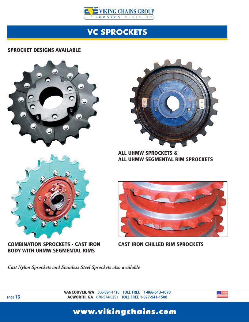
COMBINATION SPROCKETS - CAST IRONBODY WITH UHMW SEGMENTAL RIMS
ALL UHMW SPROCKETS & ALL UHMW SEGMENTAL RIM SPROCKETS
CAST IRON CHILLED RIM SPROCKETS
Cast Nylon Sprockets and Stainless Steel Sprockets also available
SPROCKET DESIGNS AVAILABLE
VC SPROCKETS
www.vikingchains.com
PAGE 17
e n v i r o d i v i s i o n
DELTA, BC 604-952-4146 TOLL FREE 1-800-324-1244VANIER, PQ 418-650-6090 TOLL FREE 1-888-650-6090
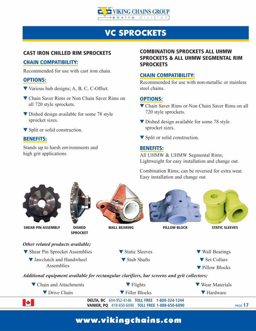
CAST IRON CHILLED RIM SPROCKETS
CHAIN COMPATIBILITY:Recommended for use with cast iron chain.
OPTIONS:t Various hub designs; A, B, C, C-Offset.
t Chain Saver Rims or Non Chain Saver Rims onall 720 style sprockets.
t Dished design available for some 78 style sprocket sizes.
t Split or solid construction.
BENEFITS:Stands up to harsh environments and high grit applications
t Shear Pin Sprocket Assemblies
t Jawclutch and HandwheelAssemblies
t Static Sleeves
t Stub Shafts
tWall Bearings
t Set Collars
t Pillow Blocks
Other related products available;
t Chain and Attachments
t Drive Chain
t Flights
t Filler Blocks
tWear Materials
t Hardware
Additional equipment available for rectangular clarifiers, bar screens and grit collectors;
COMBINATION SPROCKETS ALL UHMWSPROCKETS & ALL UHMW SEGMENTAL RIMSPROCKETS
CHAIN COMPATIBILITY:Recommended for use with non-metallic or stainlesssteel chains.
OPTIONS:t Chain Saver Rims or Non Chain Saver Rims on all
720 style sprockets.
t Dished design available for some 78 style sprocket sizes.
t Split or solid construction.
BENEFITS:All UHMW & UHMW Segmental Rims;Lightweight for easy installation and change out.
Combination Rims; can be reversed for extra wear.Easy installation and change out.
SHEAR PIN ASSEMBLY DISHEDSPROCKET
WALL BEARING PILLOW BLOCK STATIC SLEEVES
e n v i r o d i v i s i o n
VC FLIGHTBOARDS
www.vikingchains.com
PAGE 18VANCOUVER, WA 360-694-1416 TOLL FREE 1-866-513-4078
ACWORTH, GA 678-574-0251 TOLL FREE 1-877-941-1500
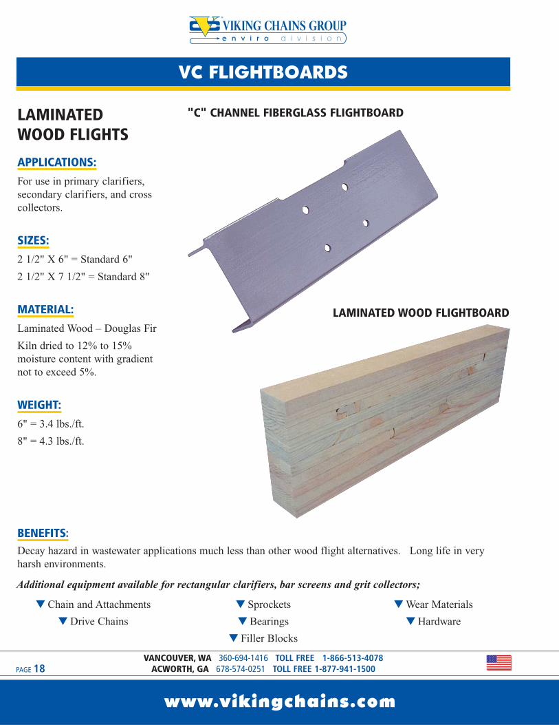
LAMINATED WOOD FLIGHTS
APPLICATIONS:For use in primary clarifiers,secondary clarifiers, and crosscollectors.
SIZES:2 1/2" X 6" = Standard 6"
2 1/2" X 7 1/2" = Standard 8"
MATERIAL:Laminated Wood – Douglas Fir
Kiln dried to 12% to 15%moisture content with gradientnot to exceed 5%.
WEIGHT:6" = 3.4 lbs./ft.
8" = 4.3 lbs./ft.
BENEFITS:Decay hazard in wastewater applications much less than other wood flight alternatives. Long life in veryharsh environments.
"C" CHANNEL FIBERGLASS FLIGHTBOARD
LAMINATED WOOD FLIGHTBOARD
t Chain and Attachments
t Drive Chains
t Sprockets
t Bearings
t Filler Blocks
tWear Materials
t Hardware
Additional equipment available for rectangular clarifiers, bar screens and grit collectors;
VC FLIGHTBOARDS
www.vikingchains.com
PAGE 19
e n v i r o d i v i s i o n
DELTA, BC 604-952-4146 TOLL FREE 1-800-324-1244VANIER, PQ 418-650-6090 TOLL FREE 1-888-650-6090
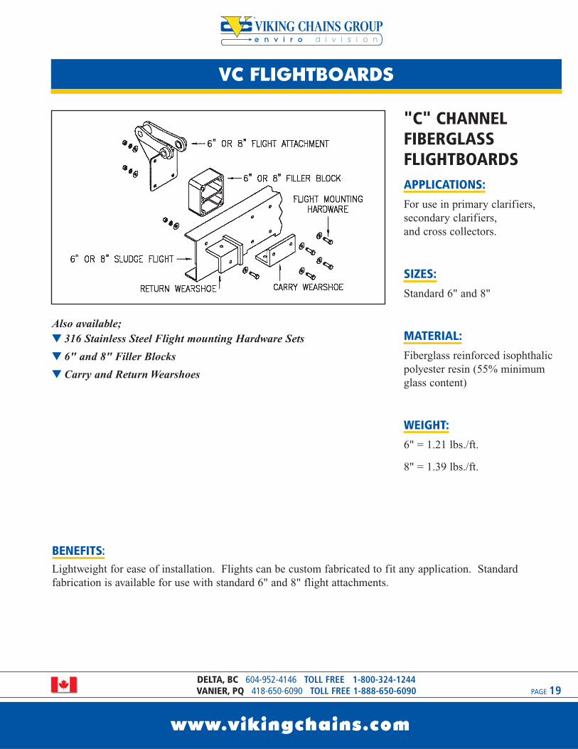
"C" CHANNELFIBERGLASSFLIGHTBOARDSAPPLICATIONS:For use in primary clarifiers,secondary clarifiers, and cross collectors.
SIZES:Standard 6" and 8"
MATERIAL:Fiberglass reinforced isophthalicpolyester resin (55% minimumglass content)
WEIGHT:6" = 1.21 lbs./ft.
8" = 1.39 lbs./ft.
BENEFITS:Lightweight for ease of installation. Flights can be custom fabricated to fit any application. Standardfabrication is available for use with standard 6" and 8" flight attachments.
Also available; t 316 Stainless Steel Flight mounting Hardware Sets
t 6" and 8" Filler Blocks
t Carry and Return Wearshoes

e n v i r o d i v i s i o n
VC ALUMINIUM FLIGHTBOARDS
www.vikingchains.com
PAGE 20VANCOUVER, WA 360-694-1416 TOLL FREE 1-866-513-4078
ACWORTH, GA 678-574-0251 TOLL FREE 1-877-941-1500
ALUMINUM FLIGHTBOARDS
APPLICATIONS:For use in primary clarifiers,secondary clarifiers, and crosscollectors.
SIZE:2 1/2” X 7” for use with 8” flightattachments. Can be supplied incustom cut lengths up to 32 feet long.
WEIGHT:2.41 lbs./ft.
MATERIAL:6060-T6 Aluminum
BENEFITS:t Lightweight for easy installation.
t No need for filler blocks.
t No notching or drilling required.
t Can be completely assembled in advance with minor field adjustments.
t Can be repaired and welded on-site or in a shop.
t Can be RECYCLED for salvage value after use.

VC ALUMINIUM FLIGHTBOARDS
www.vikingchains.com
PAGE 21
e n v i r o d i v i s i o n
DELTA, BC 604-952-4146 TOLL FREE 1-800-324-1244VANIER, PQ 418-650-6090 TOLL FREE 1-888-650-6090
ALUMINIUM EXTRUDED
FLIGHTS CAN BE SUPPLIED
WITH;
t Carry and return wearshoesmade of UHMW.
t Hardware which includesaluminum extruded nuts andstainless steel bolts andwashers for attachingwearshoes and flightattachments.
t Rubber scraper assemblycomplete with retainer plate,stainless steel bolts andwashers, and extruded nuts.
1 1 FLIGHT
2 1 RUBBER SCRAPER
3 2 GUIDE/RETURN SHOE
5 4 SINGLE NUT
6 6 DOUBLE NUT
7 1 WIPER RETAINER
4 2 CARRYING/WEAR SHOE
ITEM QTY. DESCRIPTION
t Chain and Attachments
t Drive Chain
t Other Flights
t Sprockets
t Bearings
t Filler Blocks
tWear Materials
t Hardware
Additional equipment available for rectangular clarifiers, bar screens and grit collectors;
e n v i r o d i v i s i o n
VC WEAR MATERIALS
www.vikingchains.com
PAGE 22VANCOUVER, WA 360-694-1416 TOLL FREE 1-866-513-4078
ACWORTH, GA 678-574-0251 TOLL FREE 1-877-941-1500
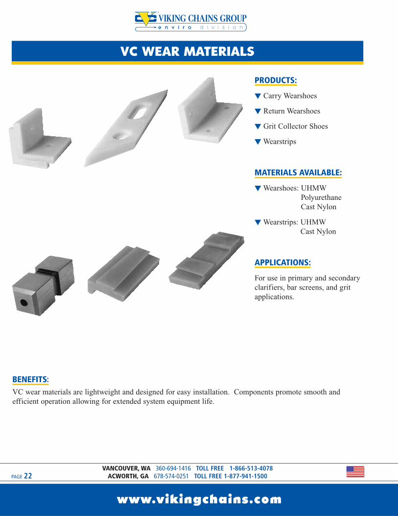
PRODUCTS:
t Carry Wearshoes
t Return Wearshoes
t Grit Collector Shoes
tWearstrips
MATERIALS AVAILABLE:
tWearshoes: UHMWPolyurethaneCast Nylon
tWearstrips: UHMW Cast Nylon
APPLICATIONS:
For use in primary and secondaryclarifiers, bar screens, and gritapplications.
BENEFITS:VC wear materials are lightweight and designed for easy installation. Components promote smooth andefficient operation allowing for extended system equipment life.
VC WEAR MATERIALS
www.vikingchains.com
PAGE 23
e n v i r o d i v i s i o n
DELTA, BC 604-952-4146 TOLL FREE 1-800-324-1244VANIER, PQ 418-650-6090 TOLL FREE 1-888-650-6090
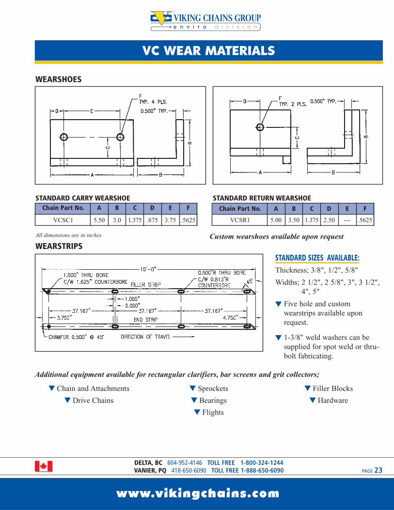
STANDARD SIZES AVAILABLE:Thickness; 3/8", 1/2", 5/8"
Widths; 2 1/2", 2 5/8", 3", 3 1/2",4", 5"
t Five hole and customwearstrips available uponrequest.
t 1-3/8" weld washers can besupplied for spot weld or thru-bolt fabricating.
Chain Part No. A B C D E F
VCSC1 5.50 3.0 1.375 .875 3.75 .5625
Chain Part No. A B C D E F
VCSR1 5.00 3.50 1.375 2.50 --- .5625
WEARSHOES
WEARSTRIPSAll dimensions are in inches Custom wearshoes available upon request
STANDARD CARRY WEARSHOE STANDARD RETURN WEARSHOE
t Chain and Attachments
t Drive Chains
t Sprockets
t Bearings
t Flights
t Filler Blocks
t Hardware
Additional equipment available for rectangular clarifiers, bar screens and grit collectors;
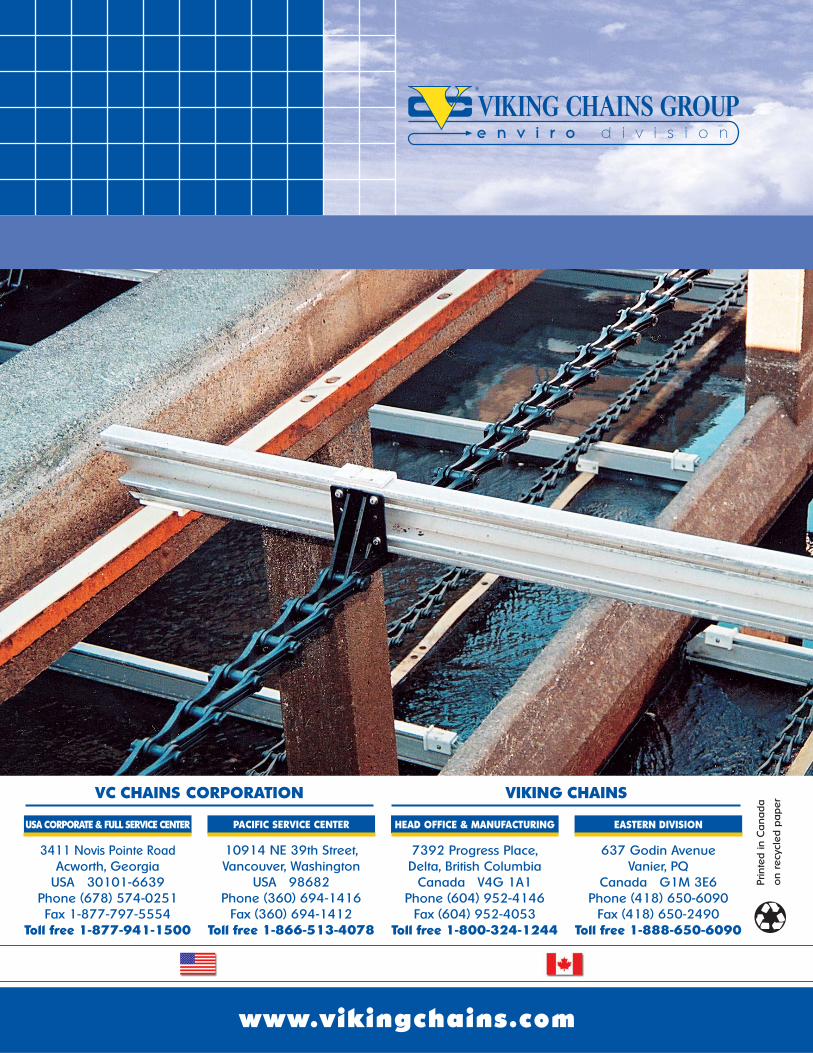
www.vikingchains.com
637 Godin AvenueVanier, PQ
Canada G1M 3E6Phone (418) 650-6090
Fax (418) 650-2490Toll free 1-888-650-6090
EASTERN DIVISION
3411 Novis Pointe RoadAcworth, Georgia
USA 30101-6639Phone (678) 574-0251Fax 1-877-797-5554
Toll free 1-877-941-1500
USA CORPORATE & FULL SERVICE CENTER
7392 Progress Place,Delta, British Columbia
Canada V4G 1A1Phone (604) 952-4146
Fax (604) 952-4053Toll free 1-800-324-1244
HEAD OFFICE & MANUFACTURING
10914 NE 39th Street,Vancouver, Washington
USA 98682Phone (360) 694-1416
Fax (360) 694-1412Toll free 1-866-513-4078
PACIFIC SERVICE CENTER
VC CHAINS CORPORATION VIKING CHAINS
Prin
ted
in C
ana
da
on
recy
cled
pa
per
e n v i r o d i v i s i o n
July 2014 - FINAL pw://Carollo/Documents/Client/CA/Sunnyvale/9265A10/Deliverables/Preliminary Design Report/DIM No 7-Primary Sedimentation Tanks.docx
Design Information Memorandum No. 7 PRE-AERATION BLOWER
(Type of blower has not been selected by the City)


Carollo Engineers/HDR
Equipment Selection and Data Sheet
PROJECT : Sunnyvale Primary Treatment Facility Design
JOB # : 9265A.10 DATE : REV: 1.0
Equip. Name : Location (Area):
MECHANICAL
Equip. Type: Pre-aeration Blowers Size: NA Connection Sizes: TBD
Weight: TBD lbs Capacity Max: 2,500 scfm Avg: Min:
Speed: TBD Class - Rating: NA Service:Pre-aeration air Status: New
Special Requirements (if any):
1:
2:
3:
ELECTRICAL/ MOTOR
Horsepower : 75 Motor Enclosure: TBD
Standby Power: Yes RPM Const: 2-Speed: Reversing VFD: No
Voltage: 480 TBD No Phase: 3
NEC Rating Class: Unclassfied Div: Group: D
Remarks:
INSTRUMENTATION
Normal Control Mode: Remote Auto
Remarks: Refer to Operating Philosophy.
NORMAL ENVIRONMENTAL CONDITIONS
Site Elevation: 109 ft Inside Building: Yes Direct Sun: No Corrosive Area: No
Damp Area: No Subject to Flooding: No Explosive Area: No Dusty: No
Other:
EQUIPMENT SELECTION
Equipment Alternate No. 1 Equipment Alternate No. 2 Equipment Alternate No. 3
Manufacturer Neuros Aerzen (K-Turbo) Hoffman
Model
Attention: Please reference attached catalog cut sheets.
USE ADDITIONAL SHEETS FOR COMMENTS IF NECESSARY
7/24/2014
Primary Pre-aeration Blowers
Area 07 - Primary Sedimentation
Tanks
Constant flowrate of 2,500 scfm
Equipment Datasheets-Sunnyvale.xls

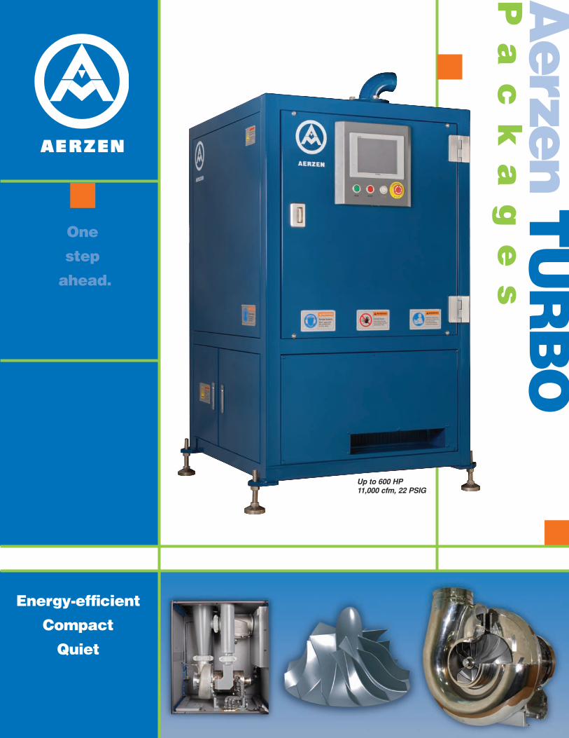
Aerzen T
UR
BO
Pa
ck
ag
es
One
step
ahead.
Energy-efficient
Compact
Quiet
Up to 600 HP11,000 cfm, 22 PSIG
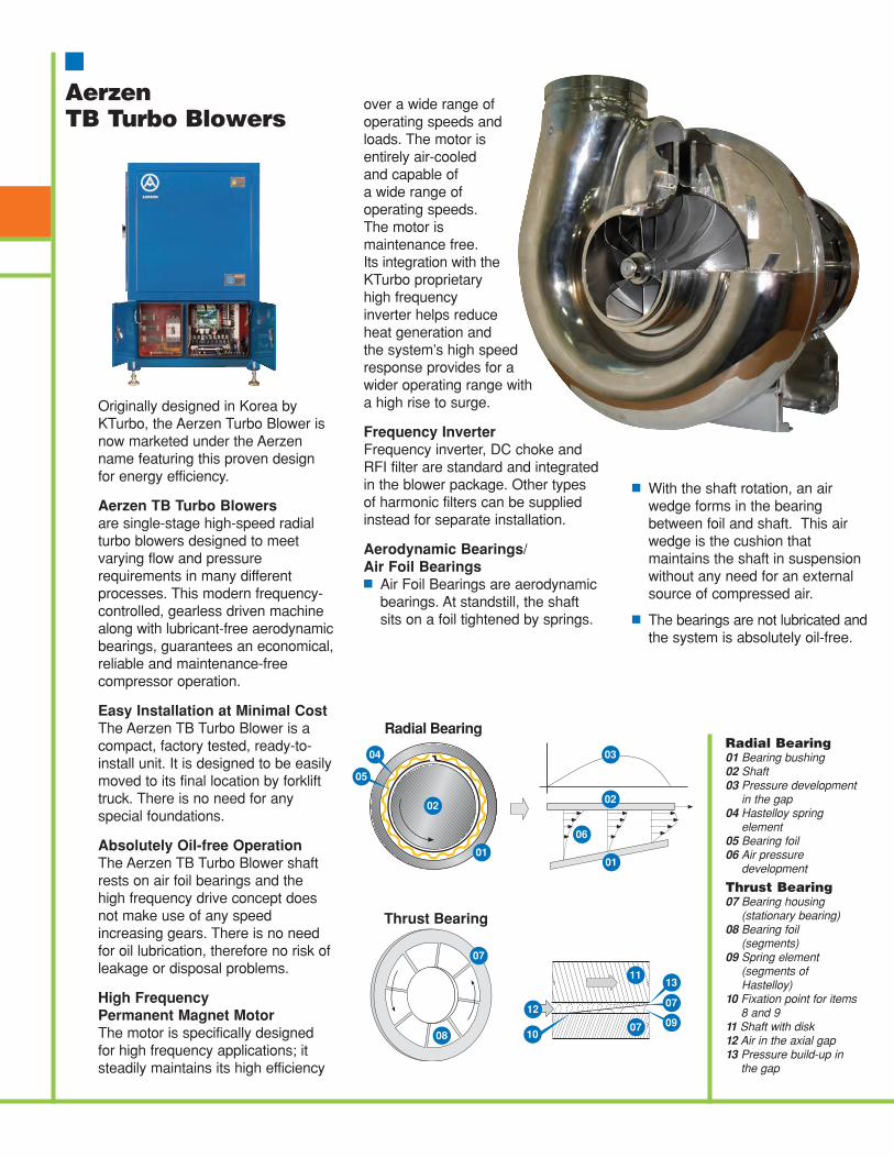
Originally designed in Korea byKTurbo, the Aerzen Turbo Blower isnow marketed under the Aerzenname featuring this proven designfor energy efficiency.
Aerzen TB Turbo Blowersare single-stage high-speed radialturbo blowers designed to meetvarying flow and pressurerequirements in many differentprocesses. This modern frequency-controlled, gearless driven machinealong with lubricant-free aerodynamicbearings, guarantees an economical,reliable and maintenance-freecompressor operation.
Easy Installation at Minimal CostThe Aerzen TB Turbo Blower is acompact, factory tested, ready-to-install unit. It is designed to be easilymoved to its final location by forklifttruck. There is no need for anyspecial foundations.
Absolutely Oil-free OperationThe Aerzen TB Turbo Blower shaftrests on air foil bearings and thehigh frequency drive concept doesnot make use of any speedincreasing gears. There is no needfor oil lubrication, therefore no risk ofleakage or disposal problems.
High Frequency Permanent Magnet MotorThe motor is specifically designedfor high frequency applications; itsteadily maintains its high efficiency
over a wide range ofoperating speeds andloads. The motor isentirely air-cooled and capable of a wide range ofoperating speeds. The motor ismaintenance free. Its integration with theKTurbo proprietaryhigh frequencyinverter helps reduceheat generation and the system’s high speedresponse provides for awider operating range witha high rise to surge.
Frequency InverterFrequency inverter, DC choke andRFI filter are standard and integratedin the blower package. Other typesof harmonic filters can be suppliedinstead for separate installation.
Aerodynamic Bearings/Air Foil Bearings■ Air Foil Bearings are aerodynamic
bearings. At standstill, the shaftsits on a foil tightened by springs.
Aerzen TB Turbo Blowers
11
07 09
13
07
02
01
03
02
05
04
01
08
07
06
Radial Bearing
Thrust Bearing
12
10
Radial Bearing01 Bearing bushing02 Shaft03 Pressure development
in the gap04 Hastelloy spring
element05 Bearing foil06 Air pressure
development
Thrust Bearing07 Bearing housing
(stationary bearing)08 Bearing foil
(segments)09 Spring element
(segments ofHastelloy)
10 Fixation point for items8 and 9
11 Shaft with disk12 Air in the axial gap13 Pressure build-up in
the gap
■ With the shaft rotation, an airwedge forms in the bearingbetween foil and shaft. This airwedge is the cushion thatmaintains the shaft in suspensionwithout any need for an externalsource of compressed air.
■ The bearings are not lubricated andthe system is absolutely oil-free.
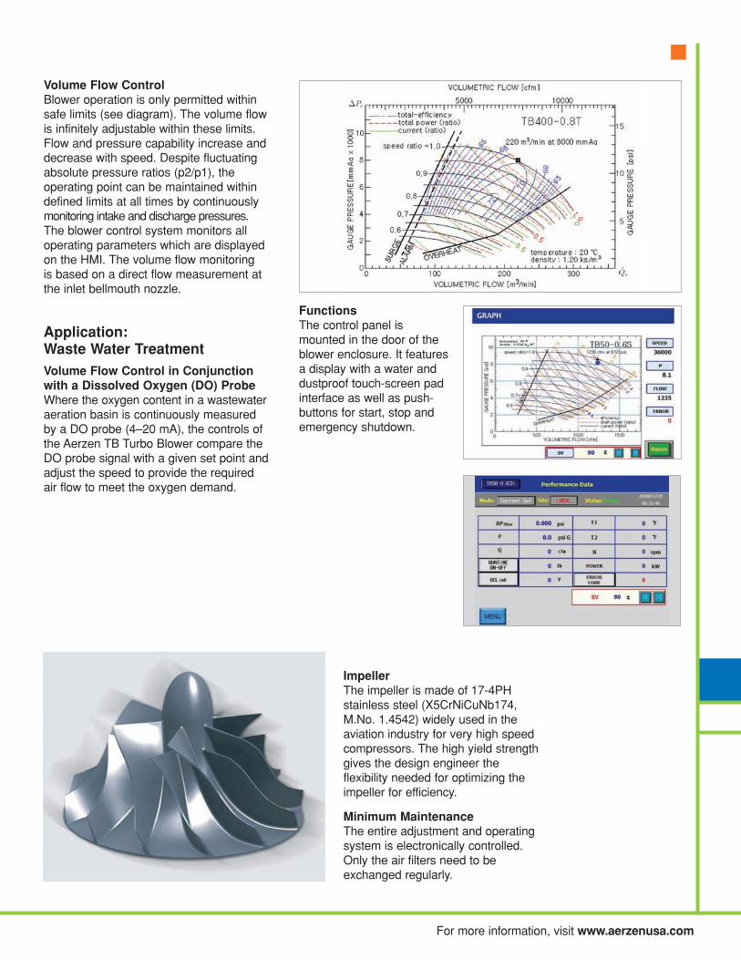
For more information, visit www.aerzenusa.com
ImpellerThe impeller is made of 17-4PHstainless steel (X5CrNiCuNb174,M.No. 1.4542) widely used in theaviation industry for very high speedcompressors. The high yield strengthgives the design engineer theflexibility needed for optimizing theimpeller for efficiency.
Minimum MaintenanceThe entire adjustment and operatingsystem is electronically controlled.Only the air filters need to beexchanged regularly.
FunctionsThe control panel ismounted in the door of theblower enclosure. It featuresa display with a water anddustproof touch-screen padinterface as well as push-buttons for start, stop andemergency shutdown.
Volume Flow ControlBlower operation is only permitted withinsafe limits (see diagram). The volume flowis infinitely adjustable within these limits.Flow and pressure capability increase anddecrease with speed. Despite fluctuatingabsolute pressure ratios (p2/p1), theoperating point can be maintained withindefined limits at all times by continuouslymonitoring intake and discharge pressures.The blower control system monitors alloperating parameters which are displayedon the HMI. The volume flow monitoring is based on a direct flow measurement atthe inlet bellmouth nozzle.
Application: Waste Water Treatment
Volume Flow Control in Conjunctionwith a Dissolved Oxygen (DO) ProbeWhere the oxygen content in a wastewateraeration basin is continuously measuredby a DO probe (4–20 mA), the controls ofthe Aerzen TB Turbo Blower compare theDO probe signal with a given set point andadjust the speed to provide the requiredair flow to meet the oxygen demand.
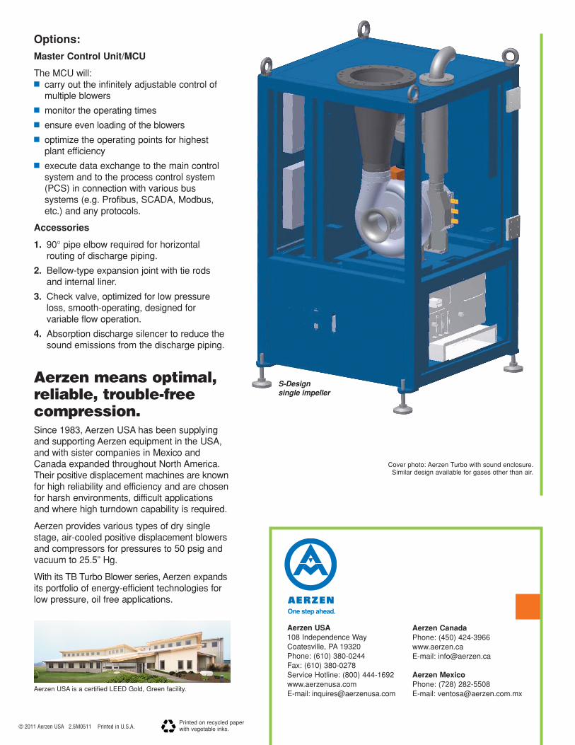
Aerzen means optimal,reliable, trouble-free compression.Since 1983, Aerzen USA has been supplyingand supporting Aerzen equipment in the USA,and with sister companies in Mexico andCanada expanded throughout North America.Their positive displacement machines are knownfor high reliability and efficiency and are chosenfor harsh environments, difficult applicationsand where high turndown capability is required.
Aerzen provides various types of dry singlestage, air-cooled positive displacement blowersand compressors for pressures to 50 psig andvacuum to 25.5” Hg.
With its TB Turbo Blower series, Aerzen expandsits portfolio of energy-efficient technologies forlow pressure, oil free applications.
© 2011 Aerzen USA 2.5M0511 Printed in U.S.A.
Aerzen CanadaPhone: (450) 424-3966www.aerzen.caE-mail: [email protected]
Aerzen MexicoPhone: (728) 282-5508E-mail: [email protected]
Aerzen USA108 Independence WayCoatesville, PA 19320Phone: (610) 380-0244Fax: (610) 380-0278Service Hotline: (800) 444-1692www.aerzenusa.comE-mail: [email protected]
Cover photo: Aerzen Turbo with sound enclosure. Similar design available for gases other than air.
Aerzen USA is a certified LEED Gold, Green facility.
Printed on recycled paper with vegetable inks.
S-Designsingle impeller
Options:
Master Control Unit/MCU
The MCU will:■ carry out the infinitely adjustable control of
multiple blowers
■ monitor the operating times
■ ensure even loading of the blowers
■ optimize the operating points for highestplant efficiency
■ execute data exchange to the main controlsystem and to the process control system(PCS) in connection with various bussystems (e.g. Profibus, SCADA, Modbus,etc.) and any protocols.
Accessories
1. 90° pipe elbow required for horizontalrouting of discharge piping.
2. Bellow-type expansion joint with tie rodsand internal liner.
3. Check valve, optimized for low pressureloss, smooth-operating, designed forvariable flow operation.
4. Absorption discharge silencer to reduce thesound emissions from the discharge piping.
July 2014 - FINAL pw://Carollo/Documents/Client/CA/Sunnyvale/9265A10/Deliverables/Preliminary Design Report/DIM No 7-Primary Sedimentation Tanks.docx
Design Information Memorandum No. 7 PRIMARY SLUDGE PUMPS
(Type of pump has not been selected by the City)

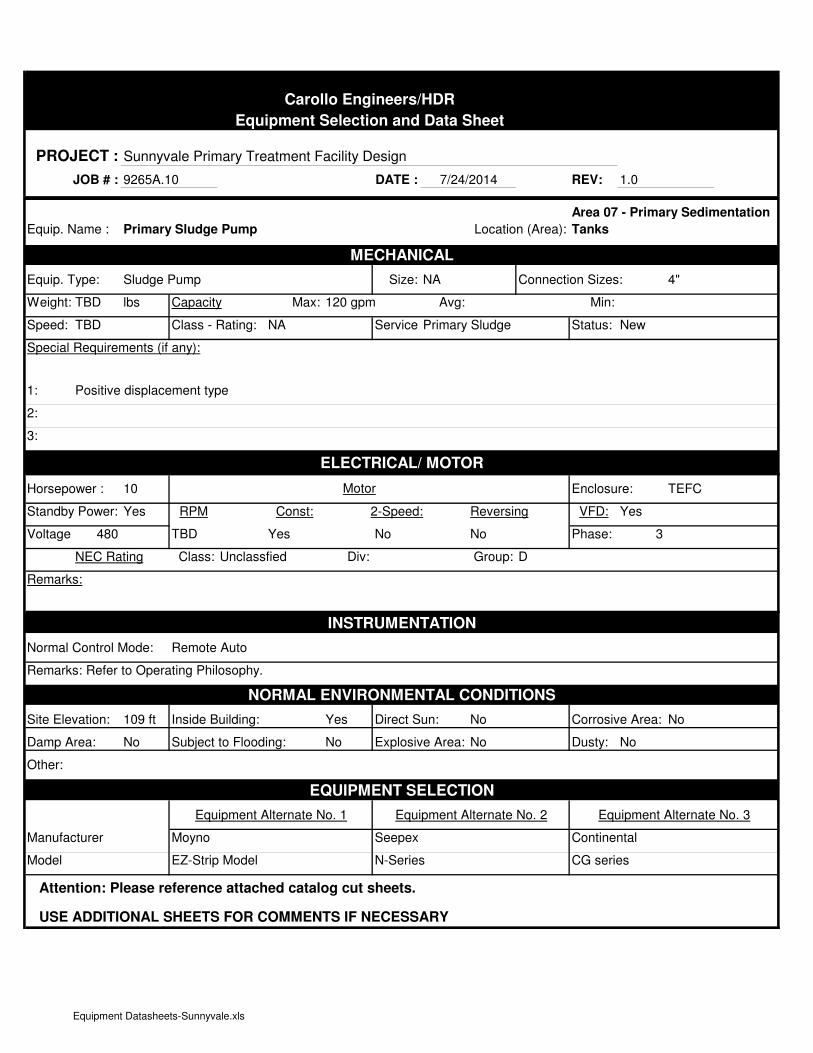
Carollo Engineers/HDR
Equipment Selection and Data Sheet
PROJECT : Sunnyvale Primary Treatment Facility Design
JOB # : 9265A.10 DATE : REV: 1.0
Equip. Name : Location (Area):
MECHANICAL
Equip. Type: Sludge Pump Size: NA Connection Sizes: 4"
Weight: TBD lbs Capacity Max: 120 gpm Avg: Min:
Speed: TBD Class - Rating: NA Service:Primary Sludge Status: New
Special Requirements (if any):
1:
2:
3:
ELECTRICAL/ MOTOR
Horsepower : 10 Motor Enclosure: TEFC
Standby Power: Yes RPM Const: 2-Speed: Reversing VFD: Yes
Voltage: 480 TBD Yes No No Phase: 3
NEC Rating Class: Unclassfied Div: Group: D
Remarks:
INSTRUMENTATION
Normal Control Mode: Remote Auto
Remarks: Refer to Operating Philosophy.
NORMAL ENVIRONMENTAL CONDITIONS
Site Elevation: 109 ft Inside Building: Yes Direct Sun: No Corrosive Area: No
Damp Area: No Subject to Flooding: No Explosive Area: No Dusty: No
Other:
EQUIPMENT SELECTION
Equipment Alternate No. 1 Equipment Alternate No. 2 Equipment Alternate No. 3
Manufacturer Moyno Seepex Continental
Model EZ-Strip Model N-Series CG series
Attention: Please reference attached catalog cut sheets.
USE ADDITIONAL SHEETS FOR COMMENTS IF NECESSARY
7/24/2014
Primary Sludge Pump
Area 07 - Primary Sedimentation
Tanks
Positive displacement type
Equipment Datasheets-Sunnyvale.xls

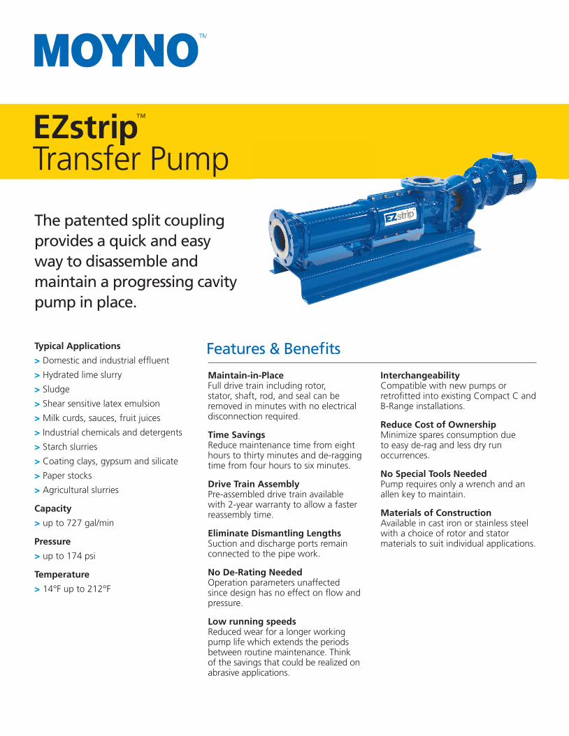
EZstrip™
Transfer Pump
Typical Applications
> Domestic and industrial effl uent
> Hydrated lime slurry
> Sludge
> Shear sensitive latex emulsion
> Milk curds, sauces, fruit juices
> Industrial chemicals and detergents
> Starch slurries
> Coating clays, gypsum and silicate
> Paper stocks
> Agricultural slurries
Capacity
> up to 727 gal/min
Pressure
> up to 174 psi
Temperature
> 14°F up to 212°F
The patented split coupling provides a quick and easy way to disassemble and maintain a progressing cavity pump in place.
Maintain-in-Place Full drive train including rotor, stator, shaft, rod, and seal can be removed in minutes with no electrical disconnection required.
Time Savings Reduce maintenance time from eight hours to thirty minutes and de-ragging time from four hours to six minutes.
Drive Train Assembly Pre-assembled drive train available with 2-year warranty to allow a faster reassembly time.
Eliminate Dismantling Lengths Suction and discharge ports remain connected to the pipe work.
No De-Rating Needed Operation parameters unaffected since design has no effect on fl ow and pressure.
Low running speeds Reduced wear for a longer working pump life which extends the periods between routine maintenance. Think of the savings that could be realized on abrasive applications.
Interchangeability Compatible with new pumps or retrofi tted into existing Compact C and B-Range installations.
Reduce Cost of Ownership Minimize spares consumption due to easy de-rag and less dry run occurrences.
No Special Tools NeededPump requires only a wrench and an allen key to maintain.
Materials of ConstructionAvailable in cast iron or stainless steel with a choice of rotor and stator materials to suit individual applications.
Features & Benefi ts
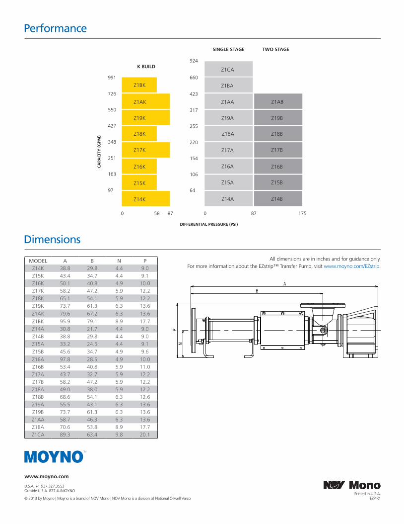
www.moyno.com
U.S.A. +1 937.327.3553 Outside U.S.A. 877.4UMOYNO
© 2013 by Moyno | Moyno is a brand of NOV Mono | NOV Mono is a division of National Oilwell VarcoPrinted in U.S.A.
EZP R1
Performance
MODEL A B N PZ14K 38.8 29.8 4.4 9.0Z15K 43.4 34.7 4.4 9.1Z16K 50.1 40.8 4.9 10.0Z17K 58.2 47.2 5.9 12.2Z18K 65.1 54.1 5.9 12.2Z19K 73.7 61.3 6.3 13.6
Z1AK 79.6 67.2 6.3 13.6
Z1BK 95.9 79.1 8.9 17.7Z14A 30.8 21.7 4.4 9.0Z14B 38.8 29.8 4.4 9.0Z15A 33.2 24.5 4.4 9.1Z15B 45.6 34.7 4.9 9.6Z16A 97.8 28.5 4.9 10.0Z16B 53.4 40.8 5.9 11.0Z17A 43.7 32.7 5.9 12.2Z17B 58.2 47.2 5.9 12.2Z18A 49.0 38.0 5.9 12.2Z18B 68.6 54.1 6.3 12.6Z19A 55.5 43.1 6.3 13.6Z19B 73.7 61.3 6.3 13.6Z1AA 58.7 46.3 6.3 13.6Z1BA 70.6 53.8 8.9 17.7Z1CA 89.3 63.4 9.8 20.1
All dimensions are in inches and for guidance only. For more information about the EZstrip™ Transfer Pump, visit www.moyno.com/EZstrip.
B
N
A
P
Dimensions
K BUILD
SINGLE STAGE TWO STAGE
Z1AK
Z19K
Z18K
Z17K
Z16K
Z15K
Z14K
Z1AA
Z19A
Z18A
Z17A
Z16A
Z15A
Z14A
Z19B
Z18B
Z17B
Z16B
Z15B
Z14B
0 058 87 87 175
97
163
251
348
427
550
726
64
106
154
220
255
317
423
DIFFERENTIAL PRESSURE (PSI)
CA
PAC
ITY
(G
PM)
Z1AB
Z1BK991
Z1BA
Z1CA660
924
July 2014 - FINAL pw://Carollo/Documents/Client/CA/Sunnyvale/9265A10/Deliverables/Preliminary Design Report/DIM No 7-Primary Sedimentation Tanks.docx
Design Information Memorandum No. 7 PRIMARY SCUM PUMPS

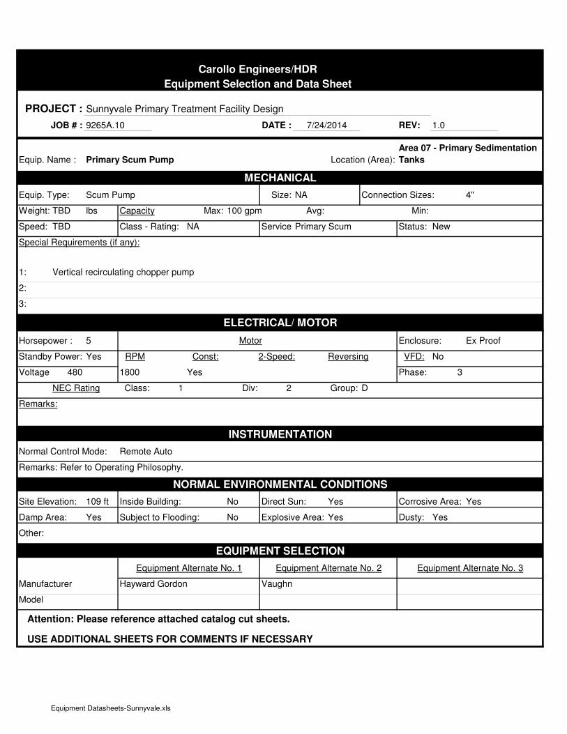
Carollo Engineers/HDR
Equipment Selection and Data Sheet
PROJECT : Sunnyvale Primary Treatment Facility Design
JOB # : 9265A.10 DATE : REV: 1.0
Equip. Name : Location (Area):
MECHANICAL
Equip. Type: Scum Pump Size: NA Connection Sizes: 4"
Weight: TBD lbs Capacity Max: 100 gpm Avg: Min:
Speed: TBD Class - Rating: NA Service:Primary Scum Status: New
Special Requirements (if any):
1:
2:
3:
ELECTRICAL/ MOTOR
Horsepower : 5 Motor Enclosure: Ex Proof
Standby Power: Yes RPM Const: 2-Speed: Reversing VFD: No
Voltage: 480 1800 Yes Phase: 3
NEC Rating Class: 1 Div: 2 Group: D
Remarks:
INSTRUMENTATION
Normal Control Mode: Remote Auto
Remarks: Refer to Operating Philosophy.
NORMAL ENVIRONMENTAL CONDITIONS
Site Elevation: 109 ft Inside Building: No Direct Sun: Yes Corrosive Area: Yes
Damp Area: Yes Subject to Flooding: No Explosive Area: Yes Dusty: Yes
Other:
EQUIPMENT SELECTION
Equipment Alternate No. 1 Equipment Alternate No. 2 Equipment Alternate No. 3
Manufacturer Hayward Gordon Vaughn
Model
Attention: Please reference attached catalog cut sheets.
USE ADDITIONAL SHEETS FOR COMMENTS IF NECESSARY
7/24/2014
Primary Scum Pump
Area 07 - Primary Sedimentation
Tanks
Vertical recirculating chopper pump
Equipment Datasheets-Sunnyvale.xls

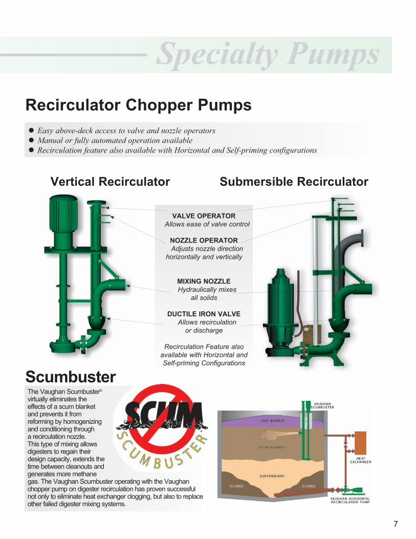
6SHFLDOW\�3XPSV5HFLUFXODWRU�&KRSSHU�3XPSV
9HUWLFDO�5HFLUFXODWRU 6XEPHUVLEOH�5HFLUFXODWRU
9$/9(�23(5$725���$OORZV�HDVH�RI�YDOYH�FRQWURO
12==/(�23(5$725���$GMXVWV�QR]]OH�GLUHFWLRQKRUL]RQWDOO\�DQG�YHUWLFDOO\
0,;,1*�12==/(���+\GUDXOLFDOO\�PL[HV
DOO�VROLGV
'8&7,/(�,521�9$/9(���$OORZV�UHFLUFXODWLRQ
RU�GLVFKDUJH
5HFLUFXODWLRQ�)HDWXUH�DOVR�DYDLODEOH�ZLWK�+RUL]RQWDO�DQG�6HOI�SULPLQJ�&RQILJXUDWLRQV
z�(DV\�DERYH�GHFN�DFFHVV�WR�YDOYH�DQG�QR]]OH�RSHUDWRUVz�0DQXDO�RU�IXOO\�DXWRPDWHG�RSHUDWLRQ�DYDLODEOHz�5HFLUFXODWLRQ�IHDWXUH�DOVR�DYDLODEOH�ZLWK�+RUL]RQWDO�DQG�6HOI�SULPLQJ�FRQILJXUDWLRQV
7KH�9DXJKDQ�6FXPEXVWHU��YLUWXDOO\�HOLPLQDWHV�WKH�HIIHFWV�RI�D�VFXP�EODQNHW�DQG�SUHYHQWV�LW�IURP�UHIRUPLQJ�E\�KRPRJHQL]LQJ�DQG�FRQGLWLRQLQJ�WKURXJK�D�UHFLUFXODWLRQ�QR]]OH���7KLV�W\SH�RI�PL[LQJ�DOORZV�GLJHVWHUV�WR�UHJDLQ�WKHLU�GHVLJQ�FDSDFLW\��H[WHQGV�WKH�WLPH�EHWZHHQ�FOHDQRXWV�DQG�JHQHUDWHV�PRUH�PHWKDQH�JDV��7KH�9DXJKDQ�6FXPEXVWHU�RSHUDWLQJ�ZLWK�WKH�9DXJKDQ�FKRSSHU�SXPS�RQ�GLJHVWHU�UHFLUFXODWLRQ�KDV�SURYHQ�VXFFHVVIXO�QRW�RQO\�WR�HOLPLQDWH�KHDW�H[FKDQJHU�FORJJLQJ��EXW�DOVR�WR�UHSODFH�RWKHU�IDLOHG�GLJHVWHU�PL[LQJ�V\VWHPV�
6FXPEXVWHU
�

July 2014 - FINAL pw://Carollo/Documents/Client/CA/Sunnyvale/9265A10/Deliverables/Preliminary Design Report/DIM No 7-Primary Sedimentation Tanks.docx
Design Information Memorandum No. 7 APPENDIX B - DIM MEETING 2 MINUTES (APRIL 17, 2014)

1 Documents\Client\CA\Sunnyvale\9265A10\Meetings\Minutes\2014-04-17-DIM Meeting 2-Meeting Minutes.doc
CONFERENCE MEMORANDUM
Project: Primary Treatment Design Conf. Date: April 17, 2014
Client: City of Sunnyvale Issue Date: May 5, 2014
Location: WPCP Training Room
Attendees: City: Bryan Berdeen Dan Hammons Tanner McGinnis Craig Mobeck Bhavani Yerrapotu Nelson Schlater Robert Rockett
Carollo: James Wickstrom CDM Smith: Dave Parry Ed Fernbach Black and Veatch:
Randy Fiorucci
HDR: Craig Olson Hany Gerges Dana Hunt Malar Perinpanayagam Eskter and Associates: Alex Ekster
Purpose: Design Information Memoranda (DIM) Meeting 2
Distribution: Attendees File: 9265A.10
Discussion: The following is our understanding of the subject matter covered in this conference. If this differs from your understanding, please notify us.
1. Decisions: The following decisions were made and will be added to the Decision Log. A. Screening
1) Provide slide gates with top seals on the bar screen and bypass channel gates at the screenings facility.
B. Primary Sedimentation Tanks 1) Design Flows for Primary Treatment Facility
a) The primary sedimentation tanks (PSTs) will be designed for overflow rate (OFR) of 2,000 gpd/sf at max month (MM) flow of 26.2 mgd in 2035 and all tanks in service. (Confirms Master Plan Primary Treatment Technical Memorandum (TM) finding.)
b) Primary treatment facilities are sized for treatment of MM flow of 26.2 mgd (2035). (Confirms TM finding.)
2) Primary influent conveyance/channel a) 66-inch pipe will convey primary influent from headcell effluent channel to PST
influent channel and will enter at the center of the channel from bottom. b) Ferric chloride will be injected into primary influent pipe right after headcell
effluent channel and polymer will be injected at mid-way point of primary pipe between headcell effluent channel and PSTs.
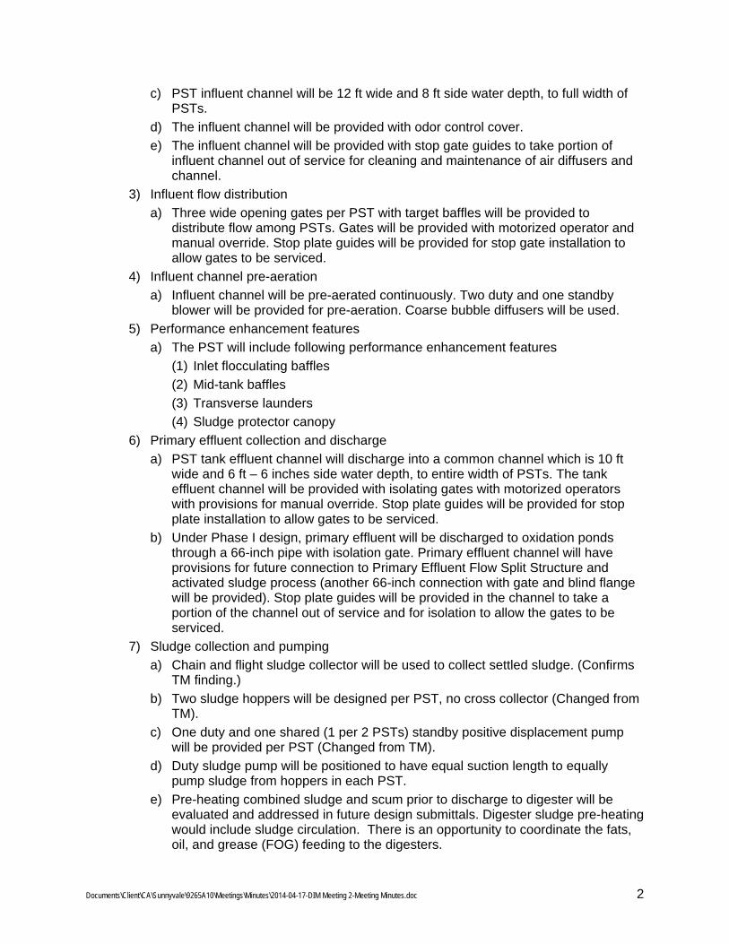
Documents\Client\CA\Sunnyvale\9265A10\Meetings\Minutes\2014-04-17-DIM Meeting 2-Meeting Minutes.doc 2
c) PST influent channel will be 12 ft wide and 8 ft side water depth, to full width of PSTs.
d) The influent channel will be provided with odor control cover. e) The influent channel will be provided with stop gate guides to take portion of
influent channel out of service for cleaning and maintenance of air diffusers and channel.
3) Influent flow distribution a) Three wide opening gates per PST with target baffles will be provided to
distribute flow among PSTs. Gates will be provided with motorized operator and manual override. Stop plate guides will be provided for stop gate installation to allow gates to be serviced.
4) Influent channel pre-aeration a) Influent channel will be pre-aerated continuously. Two duty and one standby
blower will be provided for pre-aeration. Coarse bubble diffusers will be used. 5) Performance enhancement features
a) The PST will include following performance enhancement features (1) Inlet flocculating baffles (2) Mid-tank baffles (3) Transverse launders (4) Sludge protector canopy
6) Primary effluent collection and discharge a) PST tank effluent channel will discharge into a common channel which is 10 ft
wide and 6 ft – 6 inches side water depth, to entire width of PSTs. The tank effluent channel will be provided with isolating gates with motorized operators with provisions for manual override. Stop plate guides will be provided for stop plate installation to allow gates to be serviced.
b) Under Phase I design, primary effluent will be discharged to oxidation ponds through a 66-inch pipe with isolation gate. Primary effluent channel will have provisions for future connection to Primary Effluent Flow Split Structure and activated sludge process (another 66-inch connection with gate and blind flange will be provided). Stop plate guides will be provided in the channel to take a portion of the channel out of service and for isolation to allow the gates to be serviced.
7) Sludge collection and pumping a) Chain and flight sludge collector will be used to collect settled sludge. (Confirms
TM finding.) b) Two sludge hoppers will be designed per PST, no cross collector (Changed from
TM). c) One duty and one shared (1 per 2 PSTs) standby positive displacement pump
will be provided per PST (Changed from TM). d) Duty sludge pump will be positioned to have equal suction length to equally
pump sludge from hoppers in each PST. e) Pre-heating combined sludge and scum prior to discharge to digester will be
evaluated and addressed in future design submittals. Digester sludge pre-heating would include sludge circulation. There is an opportunity to coordinate the fats, oil, and grease (FOG) feeding to the digesters.
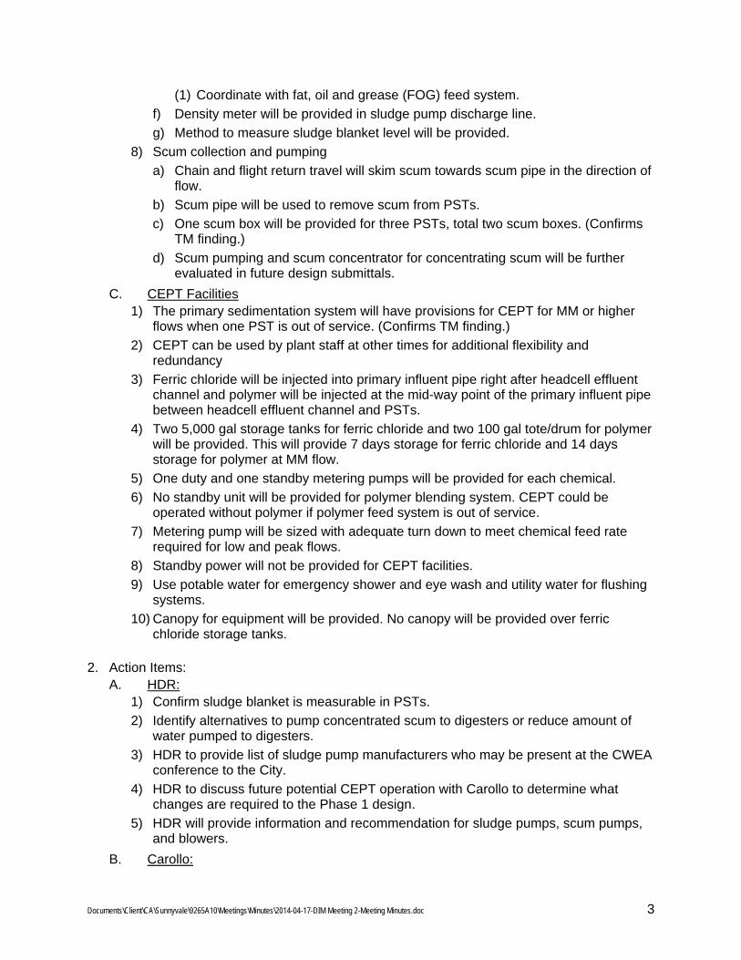
Documents\Client\CA\Sunnyvale\9265A10\Meetings\Minutes\2014-04-17-DIM Meeting 2-Meeting Minutes.doc 3
(1) Coordinate with fat, oil and grease (FOG) feed system. f) Density meter will be provided in sludge pump discharge line. g) Method to measure sludge blanket level will be provided.
8) Scum collection and pumping a) Chain and flight return travel will skim scum towards scum pipe in the direction of
flow. b) Scum pipe will be used to remove scum from PSTs. c) One scum box will be provided for three PSTs, total two scum boxes. (Confirms
TM finding.) d) Scum pumping and scum concentrator for concentrating scum will be further
evaluated in future design submittals. C. CEPT Facilities
1) The primary sedimentation system will have provisions for CEPT for MM or higher flows when one PST is out of service. (Confirms TM finding.)
2) CEPT can be used by plant staff at other times for additional flexibility and redundancy
3) Ferric chloride will be injected into primary influent pipe right after headcell effluent channel and polymer will be injected at the mid-way point of the primary influent pipe between headcell effluent channel and PSTs.
4) Two 5,000 gal storage tanks for ferric chloride and two 100 gal tote/drum for polymer will be provided. This will provide 7 days storage for ferric chloride and 14 days storage for polymer at MM flow.
5) One duty and one standby metering pumps will be provided for each chemical. 6) No standby unit will be provided for polymer blending system. CEPT could be
operated without polymer if polymer feed system is out of service. 7) Metering pump will be sized with adequate turn down to meet chemical feed rate
required for low and peak flows. 8) Standby power will not be provided for CEPT facilities. 9) Use potable water for emergency shower and eye wash and utility water for flushing
systems. 10) Canopy for equipment will be provided. No canopy will be provided over ferric
chloride storage tanks.
2. Action Items: A. HDR:
1) Confirm sludge blanket is measurable in PSTs. 2) Identify alternatives to pump concentrated scum to digesters or reduce amount of
water pumped to digesters. 3) HDR to provide list of sludge pump manufacturers who may be present at the CWEA
conference to the City. 4) HDR to discuss future potential CEPT operation with Carollo to determine what
changes are required to the Phase 1 design. 5) HDR will provide information and recommendation for sludge pumps, scum pumps,
and blowers. B. Carollo:

Documents\Client\CA\Sunnyvale\9265A10\Meetings\Minutes\2014-04-17-DIM Meeting 2-Meeting Minutes.doc 4
1) Resolve issues associated with collection system overflows upstream of the headworks as it relates to impacts on reliability of the headworks facilities.
2) Discuss utilities (buried, utility trenches and tunnels) for all piping in Phase 1 including sludge and scum piping to digesters as part of Site Layout and Conceptual Utilities work.
3) Include Primary Effluent Flow Splitting concepts for split treatment in the Basis of Design documentation.
3. DIM Meetings Schedule A. DIM Meetings schedule has been revised to have total six meetings to include items
which were scheduled but not presented in previous meetings and to allow sufficient time for discussions. Upcoming DIM meetings include: 1) DIM Meeting 3 – May 7th 2) DIM Meeting 4 – May 15th 3) DIM Meeting 5 – June 19th 4) DIM Meeting 6 – June 26th
4. Review DIM Meeting 1 Minutes A. Decisions: The group reviewed and confirmed key decisions made during DIM
Meeting 1. 1) Decision 6.009: Carollo confirmed that the decision to use the modified COANDA for
design of the project would be further discussed and documented in an Appendix attached to DIM No. 6, Grit Removal and Grit Handling. The Program Management team indicated they would provide references for the use of the COANDA unit in conditions where grit slurry approach “primary sludge like” conditions.
B. Action Items: The group reviewed action items from DIM Meeting 1. 1) Action Item 163: City staff indicated that past screenings data from when the City
operated screens was not available. 2) Action Item 164: City staff indicated that slide gates with top seals should be
provided on the bar screen and bypass channel gates at the screenings facility so that the bar screen channel could be completely sealed off from the influent and effluent channels. The potential for passive overflow over the top of the gates was not desired.
3) Action Item 167: City staff reconfirmed the direction to use the modified COANDA grit washers for the project.
4) Action Item 168: Craig Mobeck indicated that a list of anticipated sole source items will need to be provided by the design team. Craig will request the necessary information from Carollo.
C. City staff requested that the master planning and design teams resolve issues associated with collection system overflows upstream of the headworks as it relates to impacts on reliability of the headworks facilities..
5. Primary Sedimentation Tanks (DIM No. 7) A. Design Flows for Primary Treatment
1) PSTs will be designed for max month flow of 26.2 mgd in 2035 and all six tanks in service
B. Key decisions from Master Plan Primary Treatment TM
Documents\Client\CA\Sunnyvale\9265A10\Meetings\Minutes\2014-04-17-DIM Meeting 2-Meeting Minutes.doc 5
1) The PSTs will be designed based on key decisions and recommendations from Master Plan Primary Treatment TM except following changes: a) Provide two sludge hoppers per PST, no cross collector b) Provide one dedicated and one shared standby sludge pump per PST
The TM presented one sludge hopper per PST and a cross collector to the rake sludge brought by chain and flight to sludge hopper; and one duty and one standby sludge pump for two PSTs. Based on reviewers’ comments for sludge pumps to provide more redundancy, HDR revisited number of sludge pumps to be provided for the PSTs. Per HDR internal discussions, it was recommended to use more sludge pumps and for possible elimination of cross collector to add another sludge hopper per PST. This resulted in one duty and one shared standby sludge pump per PST, no cross collector and two sludge hoppers per PST. Documentation for the above change in TM will be included in draft DIM.
C. Primary Influent Conveyance and Influent Channel 1) A 66-inch diameter pipe will convey primary influent flow from grit removal facility to
PST influent channel, entering the channel at center from bottom. 2) Ferric chloride and polymer for CEPT will be injected into PI pipe downstream of
headcell. Ferric chloride will be injected into the PI pipe right after Headcell effluent channel and polymer will be injected at half way point between the Headcell and PSTs. Influent channel pre-aeration, target baffle and inlet flocculating baffle will provide sufficient mixing required for flocculation and coagulation prior to solids settling.
3) Location of PI pipe in PST influent channel will affect flow distribution to PSTs by an average of +/- 20 percent when all PSTs are online. The PSTs with performance enhancement features are designed for an OFR of 2,000 gpd/sf at MM flow of 26.2 mgd in 2035. These PSTs will handle higher OFRs caused by unbalanced flow distribution.
4) The PST influent channel will be 12 ft wide and 8 ft side water depth, to full width of PSTs and will maintain 2 ft of free board. The channel will provide flow velocity of 0.42 ft/sec at MM flow and will be covered for odor control.
D. Influent Flow Distribution 1) Methods of influent flow distribution to PSTs were discussed. Submerged ports and
orifices would provide good flow distribution but would restrict scum flow to the PSTs. Wide opening gate with target baffles were recommended but would lead to unbalanced flow distribution, but as mentioned previously, the PSTs can handle higher OFRs caused by unbalanced flow distribution without adverse impacts on performance. They also allow scum to enter PSTs.
2) City staffed suggested using different size gates to PSTs to create equal headloss for flow distribution. HDR clarified that different size gates would not be an efficient way of flow distribution for variable influent flow. Wide opening gates with target baffles will be used for influent flow distribution to PSTs.
E. Influent Channel Pre-aeration 1) It was observed that the aerated grit removal systems upstream of existing PSTs
provides sufficient flocculation prior to solids settling in PSTs. With the Headcell system upstream of new PSTs, there would be no air flocculation to primary influent. Therefore pre-aeration will be provided in the influent channel to promote flocculation, to keep solids in suspension, to scrub air, to promote floatables and to
Documents\Client\CA\Sunnyvale\9265A10\Meetings\Minutes\2014-04-17-DIM Meeting 2-Meeting Minutes.doc 6
promote good flow distribution. The influent channel will provide five minutes retention time for pre-aeration at MM flow. Alex mentioned that five minutes retention time may not be sufficient for pre-aeration. He recommended that the influent channel shall be widened to 24 ft to provide a minimum of 10 minutes retention time and to minimize influent velocity in the channel which will increase good flow distribution. Per discussions at the meeting the cost vs. advantage to widening the influent channel were determined to not be required since the plant receives flow less than MM flow most of the time. Therefore the width of influent channel will remain at 12 ft.
2) The channel will be aerated at a rate of 0.12 cu ft/gal of influent flow. 3) Coarse bubble air diffusers will be used to pre-aerate influent channel. 4) Pre-aeration will be continuously and one duty and one stand-by pre-aeration
blowers will be designed and sized. (Since the meeting, a change was made to use 2 duty and 1 standby blowers to accommodate the required air flow range required to cover the range of influent flows to the PSTs)
F. Performance Enhancement Features of PSTs 1) The new PSTs will include performance enhancement features of inlet flocculating
perforated baffles, mid-tank baffles, transverse launders and sludge protector canopy. Inlet flocculating baffle will be located 9 ft from inlet wall. Mid tank baffles will be located at 35 ft and 65 ft. From CFD modeling, four transverse launders will be located at 7 ft interval and the last launder will be at 14 ft from end wall.
2) Functions, location and installations of sludge protector canopy were discussed. Sludge protector canopy with opening in between panels will help to release air from sludge. A question was raised how to measure the sludge blanket depth due to the sludge protector canopy interference with ultra-sonic meter. HDR explained that the sludge protector canopy with openings may allow the use of ultra-sonic meters for sludge blanket depth measurement and if not, sludge blanket can be measured beyond the sludge protector canopy. HDR will locate ultra-sonic meter to read sludge blanket depth.
3) Regarding the question how much improved removal efficiency is expected due to PST performance enhancement features, HDR responded that CFD modeling of PSTs with above mentioned features projected 18 percent improvement in effluent TSS removal as outlined in the Primary Treatment TM.
G. Primary Effluent Collection and Discharge 1) Four transverse launders in the PST will discharge into tank effluent channel which
will discharge into a common effluent channel. The effluent channel will be 10 ft wide and 6 ft – 6 inches side water depth, to entire with of PSTs.
2) A 66 inch pipe will convey primary effluent from PSTs to oxidation ponds and a second pipe with blind flange will be provided at the primary effluent channel for future conveyance to the future PE flow split structure and activated sludge process. Details of primary effluent flow splitting will be further developed under the master planning work.
3) Tank effluent channel will be provided with isolation gates with motorized operators with provisions for manual override
H. Sludge Collection and Pumping 1) Full length chain and sludge collector will be used to rake settled sludge to sludge
hoppers. Scum will be skimmed on return travel of chain and flight.
Documents\Client\CA\Sunnyvale\9265A10\Meetings\Minutes\2014-04-17-DIM Meeting 2-Meeting Minutes.doc 7
2) Two sludge hoppers per tank will be provided and cross collector was eliminated. 3) Sludge protector canopy will be provided to entire width of PST and over the sludge
hoppers to promote sludge thickening and minimize solids re-suspension. 4) Thickened sludge will be pumped from PSTs to digesters with no provision for thin
sludge pumping. 5) One duty and one shared standby pumps will be provided to each PST, for a total of
9 sludge pumps. City staff mentioned that if less pumps are used less effort for maintenance would be required. Program management (PM) team suggested an alternative to use portable (shelved) sludge pumps for standby pumps. At the end of discussion, the City decided to stay with a total of 9 pumps.
6) Density meter will be provided in sludge pump discharge lines. I. Scum Collection and Pumping
1) Helical and scum pipes were discussed for scum removal system. Helical skimmer with water/air spray system is being used for scum removal in existing PSTs. HDR recommended to use scum pipe because it is simple operation and requires less spray water. It will remove very thin scum but more water would be pumped to the digesters than with a helical scum skimmer. City staff has experience in using helical skimmers and have scum pipe experience. City prefers to use scum pipes for scum removal in new PSTs.
2) City staff requested to provide isolation to scum pipes. Isolation will be provided to scum pipes at end of the PST No. 1 and 6, and between PST No. 3 and 4 to direct scum flow from all PSTs to one scum box if the other one is out of service.
3) Water spray system or hose bib connections will be provided to clean the scum pipes.
4) City staff mentioned that scum box should be designed not to overflow under any situation.
5) Regarding potential to remove more water with the scum pipe during peak flows, City staff would like scum pipe to be programmed to tip less frequently and at a reduced angle depending on water level in the PSTs. HDR will investigate scum pipe operation in detail and a control strategy will be written to include its operation during peak flows.
6) One duty and one standby centrifugal recirculating chopper pumps will be provided to pump scum to digesters.
7) In order to reduce pumping more water to digesters, HDR will evaluate available alternatives to reduce scum volume. a) Separate water and scum with a baffle wall in the scum box and return water to
the primary influent channel with a submersible pump. b) Scum concentrator is another piece of equipment.
8) City staff mentioned that new scum pumping should include provisions for FOG facility tie-in in future. However, the horizon of the FOG facility is unknown. Therefore, it was determined that the design will not include provisions for FOG facility tie-in at this time.
9) Under current practice, the scum line is connected to the sludge and scum line and combined sludge is pre-heated in the pipe gallery prior to sending it to the digesters. Pre-heating combined primary sludge and scum will be evaluated in future design submittals.
J. Odor Control and Ventilation
Documents\Client\CA\Sunnyvale\9265A10\Meetings\Minutes\2014-04-17-DIM Meeting 2-Meeting Minutes.doc 8
1) Influent/effluent channels and effluent launders will be covered for odor control. PSTs will be designed to have provisions to cover entire area of PSTs for odor control.
2) Operation of odor control and ventilation was briefly discussed. A suggestion to consider odor control based on H2S concentration was made. It was suggested to oversize the exhaust fan with VFD motor and install H2S meters and pull air based on H2S concentration to reduce energy consumption. The odor control and ventilation will be discussed in greater detail in a future DIM meeting.
3) It was recommended to provide push/pull ventilation. K. Design Criteria
1) Design criteria was summarized and presented for above discussed items. 2) Following comments were made by the City:
a) Provide motorized operators for equipment as long as they are above flood level. b) Provide manual override to PST inlet and outlet motorized gates. c) Operators will determine how many PSTs to operate during low/min flow
conditions. d) City will evaluate different type of positive displacement pumps for sludge
pumping. They would like to understand pump operation, difficulties, service, maintenance and suitability by contacting pump manufacturers and treatment plants for different types of positive displacement pumps.
e) HDR to send a list of pump manufacturers for sludge pump selection. f) Pumps should be laid out to provide sufficient space for maintenance and
service. L. PST Control Philosophy/Failure Mode
1) General operation and isolation/out of service for PSTs, sludge pumps and scum pumps was discussed.
2) HDR to provide stop guides for inlet/outlet gates. 3) HDR to discuss how to drain influent and effluent channel, and PSTs; and where to
discharge drained flow. M. Electrical Requirements
1) PSTs will be designed based on NEC area classification Class 1, Group D. Non-covered or open to atmosphere area falls under Division 2, and areas ventilated at six air changes or more per hour fall under unclassified.
N. Equipment Procurement 1) HDR discussed equipment procurement, any equipment that City standardized on
and procurement procedures. City would like to have list of sole source equipment to meet and discuss with City’s Purchase Department.
2) All equipment covered under PST design will be selected by competitive bidding. O. Ancillary Facilities
1) The plant has water systems: 1W, 2W and 3W. 1W is potable water, 2W is potable water after backflow preventer and 3W is plant effluent. The City would like to change their water systems to “potable water” and “utility water” in future projects.
6. CEPT Facilities (DIM No. 8) A. Facilities
Documents\Client\CA\Sunnyvale\9265A10\Meetings\Minutes\2014-04-17-DIM Meeting 2-Meeting Minutes.doc 9
1) The CEPT facilities will be designed for MM or higher flows and one PST is offline. It would be operators’ preference to operate CEPT at other times for additional flexibility and redundancy.
2) Regarding the question of chemical storage in CEPT facility, CEPT facility will be designed for only chemicals to be used in primary treatment.
3) Currently, no ferric chloride feeding to digesters. It was mentioned that ferric chloride could be added to digesters for H2S control. It was also noted that ferric addition and UV disinfection are not necessarily mutually exclusive. A maximum iron residual can be stated. The risk of vivianite was also mentioned.
4) Chemical injection to primary influent was as discussed under primary influent conveyance and influent channel.
5) Design criteria was presented for ferric chloride and polymer. 6) It was mentioned that metering pump selection is critical because it should be able to
meet dosage for minimum and peak hour flow conditions. 7) Flushing connections will be provided to suction and discharge side of metering
pumps. 8) No need to provide canopy over the ferric chloride storage tanks. Provide canopy for
metering pumps and control panels. B. CEPT operation
1) Alex and the City commented that CEPT facility may be used for an extended period of time in the future. PST design does not include provisions for extended usage of CEPT. The following issues were discussed for extended usage of CEPT: a) PSTs will be designed to pump thick sludge and no provisions for thin sludge
pumping. Sludge with ferric chloride coagulation does not tend to thicken. b) Sludge handling capability of downstream processes (digesters and dewatering).
2) City asked Carollo/HDR to discuss potential CEPT operation in the future and to
address in the current design as needed.
7. Other Discussions: A. Pipe tunnel is not planned to be provided. City staff mentioned that pipe tunnel
system is very favorable for service and maintenance of any pipes. Site Layout and Conceptual Utilities work will discuss utilities (buried, utility trenches and tunnels) for all piping in Phase 1 including sludge and scum piping to digesters.
B. Tank effluent channels which discharge primary effluent into a common effluent channel will be provided with isolation gates. A 66-inch pipe with isolation gate will convey primary effluent from the PSTs to the oxidation ponds and a second pipe with isolation gate and blind flange will be provided at primary effluent channel for future conveyance to the future PE split flow structure and activated sludge process. Details of primary effluent flow splitting will be further developed under the master planning work.
8. Next Steps A. HDR will submit DIM No. 7, Primary Sedimentation Tanks to the City for review. B. HDR will submit DIM No. 8, CEPT Facilities to the City for review. C. DIM Meeting 3 is scheduled for May 7th. Carollo will confirm the date for DIM Meeting
3 with the City.
Documents\Client\CA\Sunnyvale\9265A10\Meetings\Minutes\2014-04-17-DIM Meeting 2-Meeting Minutes.doc 10
Prepared By:
Malar Perinpanayagam/Dana Hunt
mp:MP
Attachment: Decision Log

July 2014 - FINAL pw://Carollo/Documents/Client/CA/Sunnyvale/9265A10/Deliverables/Preliminary Design Report/DIM No 7-Primary Sedimentation Tanks.docx
Design Information Memorandum No. 7 APPENDIX C – PRIMARY SEDIMENTATION TANK INFLUENT
CHANNEL MODELING

2121 North California Blvd., Suite 475, Walnut Creek, CA 94596 T 925.974.2500 hdrinc.com 1
Technical Memorandum Date: Monday, June 30, 2014
Project: City of Sunnyvale Water Pollution Control Tank
Prepared by:: Hany Gerges Ph.D, P.E.
Subject: Primary Sedimentation Tank Influent Channel Modeling
Introduction A computational fluid dynamic modeling (CFD) (also known as mathematical modeling) was completed to evaluate the flow imbalance between the six new primary sedimentation tanks (PSTs). The three dimensional (3D) model was constructed to include the influent pipe, influent channel, and distribution gates, and short segment the six PSTs. Modeling the flow regime within each PST was not part of the scope of work of this technical memorandum (TM). However, a computational fluid analysis of the PST was discussed in another TM.
Background Balancing the flow between the PSTs will result on equal loading to each of the PSTs and ensure sufficient settling time which is crucial for optimal performance of the new PSTs.
In this study, a commercial CFD package called Flow3D was utilized. Flow3D solves the continuity, momentum, energy, mass balance and heat transfer equations in a multi-dimensional fashion. A 3D model of the influent pipe, the influent channel and portion of the six PSTs was constructed in AutoCAD. The file was saved as an “STL” file which the Flow 3D software can read.
The objectives of the CFD analysis were:
• Quantify the magnitude of the flow imbalance between the new PSTs if any. • Identify the optimal gate size to provide equal flow split between the PSTs. • Investigate flow imbalance between PSTs under maximum month and peak day flow
conditions.
The new design utilizes six PSTs to provide primary treatment of the head cell effluent. Flow enters the primary influent channel through one 60-inch pipe located in the middle of the channel. The flow is then divided between six PSTs. Each PST is equipped with three gates. Each gate is 2 foot-wide and 3-foot deep.
Mathematical Modeling A mathematical model of the PSTs influent channel was abstracted from the “STL” file. Preliminary design drawings were used to develop the required files to use as input to Flow3D. Figure 1 shows a three dimensional view of the PST influent channel as simulated by Flow3D.
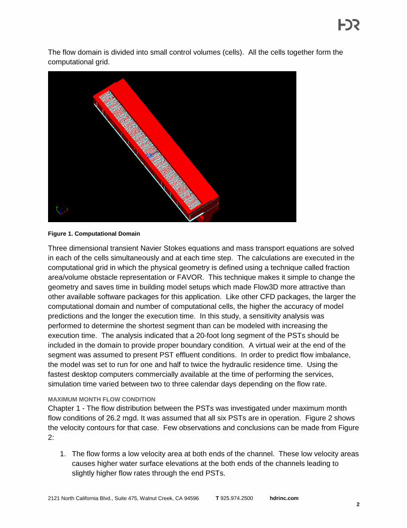
2121 North California Blvd., Suite 475, Walnut Creek, CA 94596 T 925.974.2500 hdrinc.com 2
The flow domain is divided into small control volumes (cells). All the cells together form the computational grid.
Figure 1. Computational Domain
Three dimensional transient Navier Stokes equations and mass transport equations are solved in each of the cells simultaneously and at each time step. The calculations are executed in the computational grid in which the physical geometry is defined using a technique called fraction area/volume obstacle representation or FAVOR. This technique makes it simple to change the geometry and saves time in building model setups which made Flow3D more attractive than other available software packages for this application. Like other CFD packages, the larger the computational domain and number of computational cells, the higher the accuracy of model predictions and the longer the execution time. In this study, a sensitivity analysis was performed to determine the shortest segment than can be modeled with increasing the execution time. The analysis indicated that a 20-foot long segment of the PSTs should be included in the domain to provide proper boundary condition. A virtual weir at the end of the segment was assumed to present PST effluent conditions. In order to predict flow imbalance, the model was set to run for one and half to twice the hydraulic residence time. Using the fastest desktop computers commercially available at the time of performing the services, simulation time varied between two to three calendar days depending on the flow rate.
MAXIMUM MONTH FLOW CONDITION Chapter 1 - The flow distribution between the PSTs was investigated under maximum month flow conditions of 26.2 mgd. It was assumed that all six PSTs are in operation. Figure 2 shows the velocity contours for that case. Few observations and conclusions can be made from Figure 2:
1. The flow forms a low velocity area at both ends of the channel. These low velocity areas causes higher water surface elevations at the both ends of the channels leading to slightly higher flow rates through the end PSTs.
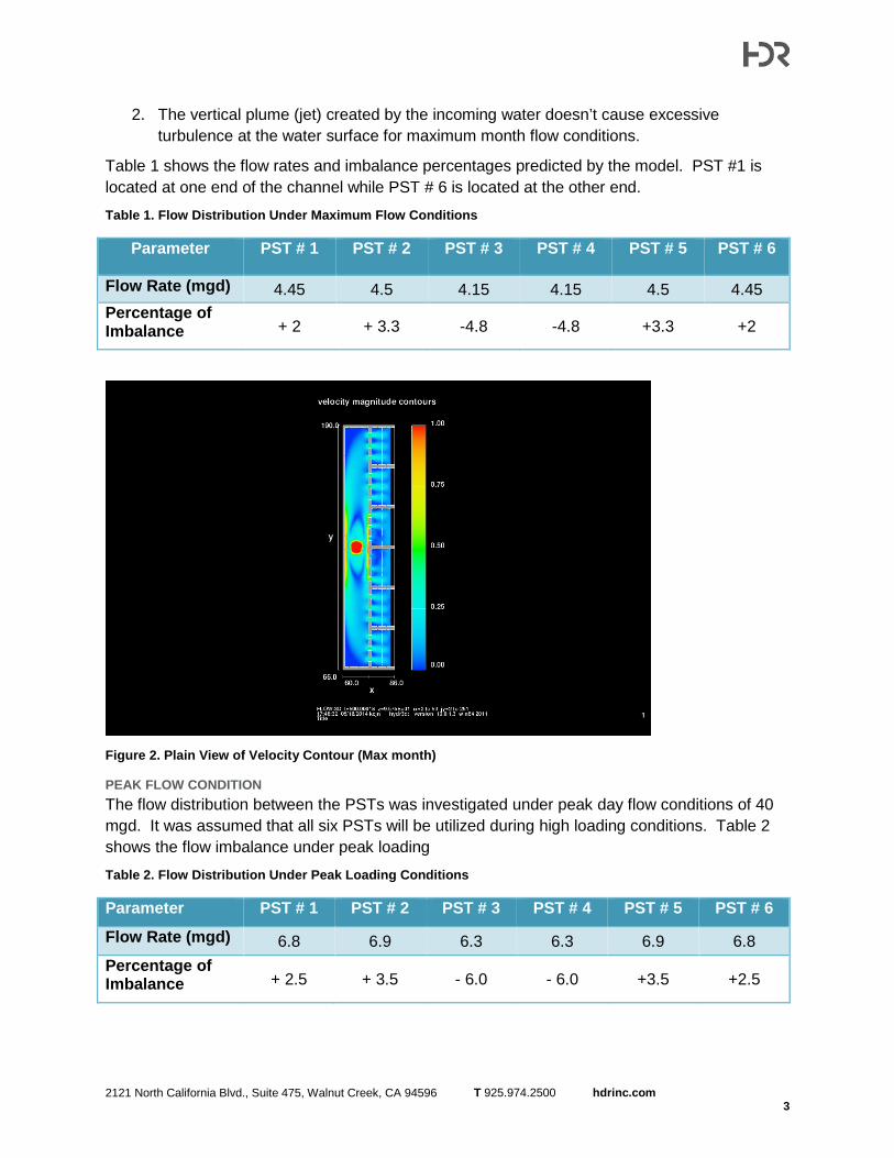
2121 North California Blvd., Suite 475, Walnut Creek, CA 94596 T 925.974.2500 hdrinc.com 3
2. The vertical plume (jet) created by the incoming water doesn’t cause excessive turbulence at the water surface for maximum month flow conditions.
Table 1 shows the flow rates and imbalance percentages predicted by the model. PST #1 is located at one end of the channel while PST # 6 is located at the other end.
Table 1. Flow Distribution Under Maximum Flow Conditions
Parameter PST # 1 PST # 2 PST # 3 PST # 4 PST # 5 PST # 6
Flow Rate (mgd) 4.45 4.5 4.15 4.15 4.5 4.45 Percentage of Imbalance + 2 + 3.3 -4.8 -4.8 +3.3 +2
Figure 2. Plain View of Velocity Contour (Max month)
PEAK FLOW CONDITION The flow distribution between the PSTs was investigated under peak day flow conditions of 40 mgd. It was assumed that all six PSTs will be utilized during high loading conditions. Table 2 shows the flow imbalance under peak loading
Table 2. Flow Distribution Under Peak Loading Conditions
Parameter PST # 1 PST # 2 PST # 3 PST # 4 PST # 5 PST # 6
Flow Rate (mgd) 6.8 6.9 6.3 6.3 6.9 6.8 Percentage of Imbalance + 2.5 + 3.5 - 6.0 - 6.0 +3.5 +2.5