City of Orting Development...
182
City of Orting Development Standards Special Provisions and Standard Details Prepared for City of Orting Prepared by
Transcript of City of Orting Development...

City of Orting Development Standards
Special Provisions and Standard Details
Prepared for
City of Orting
Prepared by
Prepared by:
Parametrix, Inc.
1019 39th Avenue SE, Suite 100
Puyallup, Washington 98374
PMX #216-1711-003 (7037)
April 1998
Revised April 1999
Revised November 2001
Revised July 2013
Prepared for:
City of Orting
P.O. Box 489
Orting, Washington 98360
CITY OF ORTING
DEVELOPMENT STANDARDS
SPECIAL PROVISIONS AND
STANDARD DETAILS
City of Orting 216-1711-003 (7037)
Orting Standards i Revised July 2013
TABLE OF CONTENTS
Page
Special Provisions Special Provisions ............................................................................................................................ SP-1
Division 1A – Public Works Projects Contract with City
Division 1B – Developer Extensions and Plat Improvement Projects
Standard Details
Concrete Curb and Gutter .................................................................................................. T-1A
Location and Width of New Driveways ............................................................................ T-2A Cement Concrete Approach ............................................................................................... T-2B
Sidewalk with Planter Strip ............................................................................................... T-3A
Sidewalk with Planter Strip Notes ..................................................................................... T-3B Sidewalk ............................................................................................................................. T-3C
Sidewalk Ramp Plans and Sections ................................................................................... T-4A
Sidewalk Ramp Details and Notes .................................................................................... T-4B Minimum Sidewalk Width at Obstructions ....................................................................... T-4C
Typical Road Section ......................................................................................................... T-5A
Typical Road Section Notes .............................................................................................. T-5B Public and Private Alley Cross Section ............................................................................. T-5C
Private Roadway Minimum Cross Section ........................................................................ T-5D
Private Roadway Minimum Cross Section Notes .............................................................. T-5E Poured In Place Monument ................................................................................................ T-6A
Monument Frame and Cover ............................................................................................. T-6B
Fire Access Requirements..................................................................................................... T-7 Dead End Private Road Requirements .............................................................................. T-8A
Cul-De-Sac Bulb Neighborhood Street ............................................................................. T-8B
Cul-De-Sac Private Access Road ...................................................................................... T-8C “T” Intersection .................................................................................................................. T-8D
Neighborhood Street Knuckle ............................................................................................ T-8E
Typical Roadway Utility Layout .......................................................................................... T-9 Thermoplastic Crosswalk.................................................................................................... T-10
Pavement Replacement .................................................................................................... T-11A
Concrete Pavement Replacement .................................................................................... T-11B Concrete Pavement Replacement Notes .......................................................................... T-11C
Asphalt Pavement Replacement ...................................................................................... T-11D
Adjustment of New and Existing Utility Structures to Finish Grade ................................. T-12
Typical Trench and Bedding Section for DIP Watermain ............................................... W-1A Water Service and Bedding Within Right-of-Way .......................................................... W-1B
5/8″ x 3/4″ Double and Single Meter Service .................................................................. W-2A
5/8″ x 3/4″ Double and Single Meter Service Notes ........................................................ W-2B
TABLE OF CONTENTS
Page
City of Orting 216-1711-003 (7037)
Orting Standards ii Revised July 2013
11/2 ″ and 2″ Meter Service .................................................................................................. W-3
Standard Fire Hydrant ....................................................................................................... W-4A Standard Fire Hydrant Notes ............................................................................................ W-4B
Fire Hydrant Guard Post ................................................................................................... W-4C
Fire Hydrant Street Markings .............................................................................................. W-5 Valve Box and Operating Nut Extender .............................................................................. W-6
Mid-Run 2″ Blowoff Assembly ........................................................................................ W-7A
End of Main 2″ Blowoff Assembly .................................................................................. W-7B Blow-Off Hydrant ............................................................................................................. W-7C
Thrust Blocking .................................................................................................................... W-8
Water Main Blocking ........................................................................................................... W-9
Water Main 2″ Air Release Valve Assembly ................................................................. W-10A
Water Main 2″ Air Release Valve Assembly ................................................................. W-10B
Water Sampling Station .................................................................................................. W-11A Water Sampling Station Details ...................................................................................... W-11B
2″ and Smaller Double Check-Valve Assembly ............................................................... W-12
2″ and Smaller Reduced Pressure Backflow Assembly ................................................. W-13A
2″ and Smaller Reduced Pressure Backflow Assembly Notes....................................... W-13B
3″ to 6″ Domestic Meter Installation .............................................................................. W-14A
3″ to 6″ Domestic Meter Installation Notes .................................................................... W-14B Tapping Sleeve and Valve Assemblies ............................................................................. W-15
Valve Marker Post ............................................................................................................. W-16
Pressure Reducing Valve with Box for 3/4″, 1″, 11/2 ″ or 2″ Service Lines ..................... W-17
Double Detector – Check Valve Assembly Installation ................................................. W-18A Double Detector – Check Valve Assembly Installation Notes ...................................... W-18B
Fire Department Connection .............................................................................................. W-19
24″ Watertight Manhole Frame and Cover ....................................................................... S-1A
24″ Locking Manhole Frame and Cover ............................................................................ S-1B
Standard 24″ Manhole Frame and Cover ........................................................................... S-1C
Sanitary Sewer or Storm Trench ........................................................................................... S-2 Type 1 Manhole ................................................................................................................. S-3A
Manhole Ring and Safety Steps .......................................................................................... S-3B
Ductile Iron Drop Connection ............................................................................................ S-3C Manhole Inside Drop Detail............................................................................................... S-4A
Outside Manhole Drop Connection .................................................................................... S-4B
Side/Building Sewer .......................................................................................................... S-5A Side Sewer Cleanout ........................................................................................................... S-5B
Typical Split Side Sewer Detail .......................................................................................... S-5C
Typical A/C Watermain Crossing Replacement .................................................................. S-6 Exterior Grease Interceptor Detail ..................................................................................... S-7A
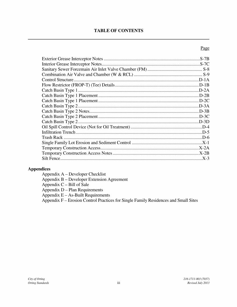
TABLE OF CONTENTS
Page
City of Orting 216-1711-003 (7037)
Orting Standards iii Revised July 2013
Exterior Grease Interceptor Notes ...................................................................................... S-7B
Interior Grease Interceptor Notes ........................................................................................ S-7C Sanitary Sewer Forcemain Air Inlet Valve Chamber (FM) ................................................. S-8
Combination Air Valve and Chamber (W & RCL) ............................................................. S-9
Control Structure ................................................................................................................ D-1A Flow Restrictor (FROP-T) (Tee) Details ........................................................................... D-1B
Catch Basin Type 1 ............................................................................................................ D-2A
Catch Basin Type 1 Placement .......................................................................................... D-2B Catch Basin Type 1 Placement .......................................................................................... D-2C
Catch Basin Type 2 ............................................................................................................ D-3A
Catch Basin Type 2 Notes.................................................................................................. D-3B
Catch Basin Type 2 Placement .......................................................................................... D-3C Catch Basin Type 2 ............................................................................................................ D-3D
Oil Spill Control Device (Not for Oil Treatment) ................................................................ D-4
Infiltration Trench ................................................................................................................. D-5 Trash Rack ............................................................................................................................ D-6
Single Family Lot Erosion and Sediment Control ............................................................... X-1
Temporary Construction Access ........................................................................................ X-2A Temporary Construction Access Notes ............................................................................. X-2B
Silt Fence ............................................................................................................................... X-3
Appendices Appendix A – Developer Checklist
Appendix B – Developer Extension Agreement Appendix C – Bill of Sale
Appendix D – Plan Requirements
Appendix E – As-Built Requirements Appendix F – Erosion Control Practices for Single Family Residences and Small Sites
City of Orting 216-1711-003 (7037)
Orting Standards SP-1 Revised July 2013
SPECIAL PROVISIONS
A. Standard Specifications
The “1998 Standard Specifications for Road, Bridge, and Municipal Construction” prepared by the
Washington State Department of Transportation and the Washington State Chapter of the American
Public Works Association (APWA) and all amendments thereto, including the “Division One
Supplement”, shall be hereinafter referred to as the “Standard Specifications” together with the laws of
the State of Washington and the ordinances of the City of Orting, so far as applicable, are hereby
included in these Specifications and shall apply as though quoted in their entirety.
B. Special Provisions
The following Special Provisions replace, amend, or supplement the Standard Specifications. All
provisions of the Standard Specifications, which are not so amended, replaced, deleted, or
supplemented, remain in full force and effect. In case of conflict, the Special Provisions shall take
precedence over the Standard Specifications. Additional Special Provisions shall be included as
part of the Special Provisions and are considered to be a supplement.
C. Division I
These Special Provisions contain two of Division I; those sections are IA and IB. All work in which
the contractor has a contract with the City, please refer to IA. Developer extensions and plat
improvements, please refer to IB and the City's Developer Extension Agreement (separate
document).
City of Orting 216-1711-003 (7037)
Orting Standards SP-2 Revised July 2013
DIVISION 1A
GENERAL REQUIREMENTS
FOR PUBLIC WORKS PROJECTS CONTRACTED BY THE CITY OF ORTING
1-01 DEFINITIONS AND TERMS
1-01.3 Definitions
Contracting Agency
Delete and add the following:
“City of Orting
P.O. Box 489
Orting, WA 98360”
Laboratory
Delete and add the following:
“Private testing laboratory employed by the Engineer or City.”
Secretary, Secretary of Transportation
Delete and add the following:
“City of Orting Council”
State
Delete and add the following:
“City of Orting
P.O. Box 489
Orting, WA 98360”
acting through its representatives
The change from “State” to “City of Orting” is intended to be used only when it refers to the Owner.
This substitution is not to be construed to apply to Washington State laws or statutes. All applicable
State of Washington or federal laws and regulations shall remain in force.
City of Orting 216-1711-003 (7037)
Orting Standards SP-3 Revised July 2013
1-02 BID PROCEDURES AND CONDITIONS
1-02.1 Prequalification of Bidders
Section 1-02.1 is deleted.
1-02.4(1) General
Add the following to the end of Section 1-02.4(1):
The Contractor shall verify the locations and elevations of all existing pipelines, structures,
grades, and utilities prior to construction. The City assumes no responsibility for any
conclusions or interpretations made by the Contractor on the basis of the information made
available.
The Contractor shall be responsible for any breakage of the existing utilities or services,
publicly or privately owned, resulting from his operations, and shall hold the City and its
agents harmless from any claim resulting from disruption of or damage to the same.
1-02.4(2) Subsurface Information
Delete section and replace with the following:
Contractor is responsible for knowing, understanding, and being familiar with the local
subsurface conditions. The City assumes no responsibility for soil conditions or
groundwater level.
1-03.8 Notice to Proceed (New Section)
Written notice to proceed will not be given until a Preconstruction Meeting has been held. No work
shall be performed until the notice has been issued.
1-05 CONTROL OF WORK
1-05.11 Final Inspection
Add the following sentences:
“The Contractor shall notify the Engineer in writing at least three (3) days prior to
completion of all work and shall certify that all items have been accomplished ready for
final inspection. If all items are not completed and ready for final inspection, no inspection
will be made at that time. The Contractor shall reschedule the final inspection as indicated
above.”
City of Orting 216-1711-003 (7037)
Orting Standards SP-4 Revised July 2013
1-05.12 Final Acceptance
Delete the third sentence of the first paragraph.
1-07 LEGAL RELATIONS AND RESPONSIBILITIES TO THE PUBLIC
1-07.13 Contractor's Responsibility for Work
1-07.13(1) General
Add the following:
The Contractor shall submit a performance bond in accordance with City of Orting, State of
Washington, Public Work performance and payment bond. The performance bond amount
shall be set by the City.
Whether or not there appears here or elsewhere herein specific reference to guarantees of all
items of materials, equipment, and workmanship, they nevertheless shall be so guaranteed
against mechanical, structural, or other defects for which the Contractor is responsible that
may develop or become evident within a period of one year from and after acceptance of the
work by the City. Such guarantees shall include care of backfilling of trenches or at
structures should the fill settle to such extent as to require refilling or resurfacing roadway
surfaces to restore the original or intended condition or grade.
This guarantee shall be understood to imply prompt attention to any remedy of such defects
as those mentioned above if and as they occur after the Contractor shall have written notice
of their existence. If the defect, in the opinion of the Owner, is of such nature as to demand
immediate repair, the Owner shall have the right to correct and cost thereof shall be borne by
the Contractor.
To support the above guarantee, the Contractor's performance bond shall remain in full force
and effect for one year following the acceptance of the project by the Owner. The bond shall
be executed by a surety company authorized to do business within the State of Washington
and it shall be subject to the approval of the attorney for the Owner.
1-07.15 Temporary Water Pollution/Erosion Control
Add the following to the end of this section:
The Contractor shall employ Best Management Practices as outlined in the DOE
Stormwater Management Manual, “Erosion and Sediment Control,” Volume II.
City of Orting 216-1711-003 (7037)
Orting Standards SP-5 Revised July 2013
1-07.16 Protection and Restoration of Property
1-07.16(5) Utility Service (New Section)
The Contractor shall maintain the operational service of water distribution, storm drainage and
sanitary sewer service systems in as continuous a manner as possible. Where services are to be shut
down, affected parties shall be notified in writing at least 48 hours and not more than 72 hours in
advance of the time and period of shut-down. The Contractor shall make every effort to keep shut
down schedules to periods of anticipated minimum usage and for the least period of time. No
utility service will be allowed to be shut down for more than 4 hours per day.
Should a shutdown of any utility be required for a period in excess of 4 hours, the Contractor shall
take necessary measures to provide temporary service. The method of all temporary utility services
shall first be approved by the City of Orting.
1-07.16(6) Restoration of Property (New Section)
The Contractor shall protect property in the vicinity of the work site and in instances of destruction or
damage, restore the item to pre-construction condition.
1-07.17 Utilities and Similar Facilities
Section 1-07.17 of the Standard Specification is supplemented by the following:
Locations and dimensions which may be provided by the City for existing facilities are in
accordance with available information obtained without uncovering, measuring, or other
verification. The contractor shall protect all private and public utilities from damage
resulting from the work.
The Contractor shall call the utility relocation center (one-call center) at 1-800-424-5555, for
field location, not less than two nor more than ten business days before the scheduled date
for commencement of excavation which may affect under ground facilities, unless otherwise
agreed upon in writing by the parties involved. A business day is defined as any day other
than Saturday, Sunday, or a legal local, state or federal holiday.
The Contractor is alerted to the existence of Chapter 19.122 RCW, a law relating to
underground utilities. Any cost to the Contractor incurred as a result of this law shall be at
the Contractor's expense.
No excavation shall begin until all known facilities, in the vicinity of the excavation area,
have been located and marked.
City of Orting 216-1711-003 (7037)
Orting Standards SP-6 Revised July 2013
1-07.18 Public Liability and Property Damage Insurance
Supplement Section 1-07.18 with the following:
The Contractor shall, before commencing work on said project, file with the City of Orting,
certificate or certificates of insurance on a form acceptable to the Owner showing insurance
coverage in force prior to or at the start of construction and including the City of Orting and
its agents as an additional named insured.
Unless otherwise specified, the public liability and property damage insurance limits for each
accident or occurrence shall be not less than $1,000,000 for bodily injury, including
accidental death to any one person and in a total amount of not less than $2,000,000 bodily
injury and property damage for each accident or occurrence. At the discretion of the City,
such limits may be increased or decreased provided that any decrease shall not reduce such
limits below the minimum limits provided by the City of Orting Municipal Code.
Insurance required to be obtained and maintained by the Contractor include: Comprehensive
automobile, general comprehensive liability, Contractor's liability insurance covering risk of
loss or damage to premises and property on which work is to be performed, and property
casualty insurance as to the perils of fire, extended coverage of vandalism and malicious
mischief.
1-07.22 Use of Explosives
Delete the entire section and add the following:
“No explosives shall be used without written permission from the City of Orting and the
Orting Fire Department.”
1-07.23 Traffic Control
When performing work within the public roadway, the Contractor shall comply with all requirements
of Section 1-07.23 of the Standard Specifications and the latest edition of the Uniform Traffic
Control Manual.
1-07.23(1)A Residential Access (New Section)
The Contractor shall notify any affected property owner at least 24 hours and not more than 36
hours prior to construction that would block access to said property. Blockage must occur only
during construction hours and shall not remain overnight. Contractor shall maintain or provide
immediate access for emergency vehicles at all times.

City of Orting 216-1711-003 (7037)
Orting Standards SP-7 Revised July 2013
1-07.28 Responsibility for Damage; Indemnification (New Section)
The Contractor hereby agrees to save the City harmless from all loss or damage occasioned to the
City or to any third person by reason of any acts or admissions on the part of the Contractor,
subcontractors, agents, employees, or persons working directly or indirectly in the performance of
the contract, including acts or omissions attributable jointly the City, its officers, agents or
employees, and shall, after reasonable notice thereof, defend and pay the expense of defending any
suit which may be commenced against the City by any third person alleging injury by reason of such
acts of omissions, and will pay any judgment which may be obtained against the City in such suit.
The Contractor agrees to repair and replace all property of the City and all property of others
damaged by himself, his employees and subcontractors and agents.
It is understood that the whole of the work is to be done at the Contractor's risk, and that he has
familiarized himself with the conditions of excavation, backfill, materials, climatic conditions and
other contingencies likely to affect the work and has made his bid accordingly and that he is to
assume the responsibility and risk of all loss or damage to materials of work which may arise from
any cause whatsoever prior to completion.
1-08 PROSECUTION AND PROGRESS
1-08.3.1 Contractor's Weekly Activity Schedule
In addition to the requirements of Section 1-08.3, the Contractor shall submit a weekly activity
schedule. The schedule shall indicate the Contractor's proposed activities for the forthcoming week
to permit the City of Orting to more efficiently and effectively implement the contract engineering
and inspection for the Contractor's operation.
The written weekly activities schedule shall be submitted to the City of Orting by the weekly
construction meeting preceding the indicated activities.
1-08.4 Prosecution of Work
Replace the first sentence with the following:
Contractor, and its duly appointed superintendent, shall attend a weekly construction
meeting at City Hall, at a timetable to be specified by the City.
1-08.5(1) Work Hours (New Section)
Work hours shall be limited to weekdays only, between the hours of 7:00 a.m. and 6:00 p.m. unless
otherwise approved in advance by the City of Orting. In addition, no work shall be done that affects
SR 162 during normal commuting hours: 6:00 a.m. to 8:00 a.m. and 4:00 p.m. to 6:00 p.m.
City of Orting 216-1711-003 (7037)
Orting Standards SP-8 Revised July 2013
1-08.10(4) Arbitration of Disputes
Delete the entire section and add the following:
“All claims, counter-claims, disputes and other matters in question between the Owner and
the Contractor arising out of or relating to this agreement or the breach thereof will be
decided by arbitration if the parties hereto mutually agree, or in a court of competent
jurisdiction within the County in which the City is located. Pending final decision of a
dispute hereunder, the Contractor shall proceed diligently with the performance of the
Contract and in accordance with the Engineer's decision.”
1-99 APWA SUPPLEMENT
The Supplement is included in the Special Provisions except as modified, deleted or supersede
herein.
City of Orting 216-1711-003 (7037)
Orting Standards SP-9 Revised July 2013
DIVISION 1B
GENERAL REQUIREMENTS
FOR DEVELOPER EXTENSION AND PLAT IMPROVEMENT PROJECTS
1-01 DEFINITIONS AND TERMS
1-01.3 Definitions
Contract
Delete and add the following:
“The written agreement is between the Developer and the Contractor. No contractual
relationship exists between the City and the Contractor.”
Contract Plans
Delete and add the following:
“The plans and specifications approved by the City.”
Engineer
Delete and add the following:
“The City's Engineer or Consultant.”
Inspector
Delete and add the following:
“The City's designated inspector.”
1-02 BID PROCEDURES AND CONDITIONS
Section does not apply. Delete entire section.
1-03 AWARD AND EXECUTION OF CONTRACT
Section does not apply. Delete entire section.
City of Orting 216-1711-003 (7037)
Orting Standards SP-10 Revised July 2013
1-04 SCOPE OF WORK
Replace the entire section with the following:
“If any conflict exists between the approved Plans/Specifications and these Special
Provisions/Details, the latter shall take precedence. Conflicts shall be resolved by the
Engineer.”
“The Contractor shall perform final cleanup within the right-of-way to the Engineer's
satisfaction. The Contractor shall maintain the right-of-way to provide safe travel to the
public. Roadways shall be cleaned off at the end of each workday.”
1-05 CONTROL OF WORK
1-05.1 Authority of Engineer
Delete and replace with the following:
“The Engineer shall be satisfied that all work is being done in accordance with the approved
Plans and the standards of the City. The decision of the Engineer is final on all questions
concerning quality and acceptability of work.”
1-05.2 Authority of Assistant's Inspections
Replace the word “contract” with the following:
“Approved Plans/Specifications and City Standards”
1-05.3 Plans and Working Drawings
Delete and replace with the following:
“City-approved Plans/Specifications”
1-05.4 Conformity With and Deviations From Plans and Stakes
Delete this section and replace with the following:
“The Developer's Engineer shall provide horizontal control during construction. The
Contractor shall take full responsibility for detailed dimensions and elevations required to
place all improvements as shown on the Plans.”
City of Orting 216-1711-003 (7037)
Orting Standards SP-11 Revised July 2013
1-05.5 Pre-Construction Meeting (New Section)
Written notice to proceed will not be given until a Preconstruction Meeting has been held. No work
shall be performed until the notice has been issued.
1-05.6 Inspection of Work and Materials
Replace the first and second paragraphs with the following:
“The Engineer or inspector may inspect all work and materials for conformity with
Plans/Specifications or City Standards. Contractor shall provide any equipment needed for
said inspection. Contractor shall supply any materials when requested by Engineer for
testing.”
Replace the third and fourth paragraphs with the following:
“The Contractor shall correct any substandard work or materials as determined by the
Engineer. The Contractor shall remove or uncover any area of completed work as requested by
the Engineer and restore said area to required standards.”
Delete remaining paragraphs.
1-05.7 Removal of Defective and Unauthorized Work
Replace with the following:
“At the direction of the Engineer, the Contractor shall immediately remove and replace all
defective work or materials that do not comply with City Standards.”
Delete Sections 1-05.9 through 1-05.12.
1-05.13 Superintendents, Labor, and Equipment of Contractor
Delete section with the following exceptions:
• First paragraph
• First sentence, second paragraph
Delete Sections 1-05.14 and 1-05.15.
City of Orting 216-1711-003 (7037)
Orting Standards SP-12 Revised July 2013
1-06 CONTROL OF MATERIAL
Replace entire section with the following:
“Prior to construction, Contractor shall deliver to City information regarding all proposed
materials and equipment to be used on the project. Contractor shall not proceed until
Engineer has reviewed and approved all materials and equipment. Information shall include
standard manufacturer's data and as requested by the Engineer.”
For Special Facilities (i.e., pump stations), the following materials shall be supplied:
A. In addition to notification of material suppliers and fabricators, the Contractor
shall also furnish for the Engineer's review and approval all required shop
drawings.
Shop drawings are defined as drawings or data which illustrate how specific
items shall be fabricated, manufactured, or installed. Shop drawings shall be
required for all shop or field fabricated or manufactured items and shall
include all information necessary for the fabrication and installation of the
item. The information shall include:
1. For fabricated items or those constructed in place, show component
sizes, layout, materials and connection details including connectors or
weld type, reinforcement schedules and sizes.
2. Shop drawings for reinforced concrete structures shall include, but not
be limited to, reinforcement bending and placing drawings.
3. Manufacturers standard catalog information and details may be
submitted; however, standard manufacturer information and
advertising literature may not necessarily be sufficient.
In addition to the above, the Contractor shall note any required exceptions to
the Contract and require deviations from the Contract Plans and any required
modifications to other details that would result from the exceptions or
deviations.

City of Orting 216-1711-003 (7037)
Orting Standards SP-13 Revised July 2013
B. Shop Drawings Submittal Procedure.
1. The Contractor shall review and sign all shop drawings to certify that
he has reviewed the shop and supplemental drawings submittal and
submit them to the Engineer attached to a transmittal form noting the
item name, quantity, location by drawing number and section in the
Specification where the item is described. The Contractor shall
clearly note on shop drawings, and in writing at the time of
submission, any changes or deviations from the Plans or
Specifications.
2. The Contractor shall submit to the Engineer three copies of all shop
drawings for review and approval. Shop drawings for major
equipment items should be submitted in one package to allow a
complete check. One copy should be sent to the City.
3. Following review of the shop drawings, the Engineer will indicate
appropriate action to be taken by the Contractor and return one copy
to the Contractor. In the event that revisions are required, the
Contractor shall follow the same procedure for the resubmittal as for
the original submittal. For scheduling purposes, the Contractor shall
allow the Engineer a minimum of ten (10) days for each review.
4. The Contractor shall be responsible for insuring that items submitted
for shop drawing submittal meet the requirements of the Contract
Documents and that the shop drawings information is complete and
accurate.
5. Approval of the shop drawings by the Engineer is only for general
conformance with the design concept of the product and general
compliance with the information given in the approved Plans. Any
action shown is subject to the requirements of the Plan and
Specifications and City Standards. The Contractor is responsible for
dimensions which shall be confirmed and correlated at the job site,
coordination of his work with that of all other trades and the
satisfactory performance of his work.
C. Samples: Samples are defined as physical examples to illustrate materials,
equipment or workmanship, and to establish standards by which completed
work is judged. Samples submitted shall be of sufficient size and quantity to
clearly illustrate functional characteristics of product or material and full
range of colors available.
City of Orting 216-1711-003 (7037)
Orting Standards SP-14 Revised July 2013
D. O&M Manuals: The Contractor shall assemble an operations and
maintenance manual for the facility which shall include, as a minimum, the
following:
1. Catalog cut sheets and individual O&M manuals for each piece and
type of equipment installed.
2. Wiring diagrams and schematics for all electrical equipment.
3. Programming instructions for control of the equipment.
The Contractor shall provide six copies of the completed O&M manual to
the Owner. Manuals shall be bound in a three-ring binder (K&M VB11-20
or equal).
1-07 LEGAL RELATIONS AND RESPONSIBILITIES TO THE PUBLIC
Delete Sections 1-07.1 through 1-07.13
1-07.15 Temporary Water Pollution/Erosion Control
Add the following to the end of this section:
The Contractor shall employ Best Management Practices as outlined in the DOE
Stormwater Management Manual, “Erosion and Sediment Control,” Volume II.
1-07.16 Protection and Restoration of Property
1-07.16(6) Restoration of Property (New Section)
The Contractor shall protect property in the vicinity of the work site and in instances of destruction or
damage, restore the item to pre-construction condition.
1-07.23 Traffic Control
1-07.23(1)A Residential Access (New Section)
The Contractor shall notify any affected property owner at least 24 hours and not more than
36 hours prior to construction that would block access to said property. Blockage must occur only
during construction hours and shall not remain overnight. Contractor shall maintain or provide
immediate access for emergency vehicles at all times.
City of Orting 216-1711-003 (7037)
Orting Standards SP-15 Revised July 2013
1-07.23(3)C Traffic Control Plans
Add the following:
“Traffic control plans will be required when work will occur on existing right-of-way. Said
plans will be submitted at the pre-construction meeting. Work shall not start until the City
has approved the traffic control plan.”
1-08 PROSECUTION AND PROGRESS
Delete Sections 1-08.1 through 1-08.2 and 1-08.4 through 1-08.5 and 1-08.8 through 1-08.10
1-08.5 Time for Completion
1-08.5(1) Work Hours (New Section)
Work hours shall be limited to weekdays, between the hours of 7:00 a.m. and 6:00 p.m. unless
otherwise approved in advance by the City of Orting. In addition, no work shall be done that affects
SR 162 during normal commuting hours: 6:00 a.m. to 8:00 a.m. and 4:00 p.m. to 6:00 p.m. Work is
permitted on Saturdays between the hours of 9:00 a.m. and 5:00 p.m. No work shall be done on City
observed holidays without written approval from the City. All requested additional working days shall
be given to the City 48 hours in advance of the holiday or weekend to be worked on. All inspection
will be billed at time-and-a-half for a minimum of 4 hours.
Delete Section 1-09.
City of Orting 216-1711-003 (7037)
Orting Standards SP-16 Revised July 2013
DIVISION 2
EARTHWORK
2-01 CLEARING, GRUBBING AND ROADSIDE CLEANUP
2-01.1 Description
Delete the third paragraph of this section and replace with the following:
“Roadside cleanup,” shall mean work required to give the construction activities completed
an attractive, finished appearance.
2-01.2 Disposal of Usable Material and Debris
Delete the third paragraph of this section and replace with the following:
Refuse and debris shall be hauled to a waste site secured by the Contractor and shall be
disposed of in such a manner as to meet all requirements of state, county, and municipal
regulations regarding health, safety and public welfare.
2-02 REMOVAL OF STRUCTURES AND OBSTRUCTIONS
2-02.1 Description
Supplement this section with the following:
The work shall consist of the removal and disposal or salvaging of existing improvements,
including pavements, concrete road structures, pipe fittings, valves, fire hydrants, manholes,
and other items necessary for the accomplishment of the improvement.
2-02.3 Construction Details
2-02.3(1) General Requirements
Supplement this section with the following:
The removal of street improvements shall be conducted in such a manner as not to damage
utilities and any portion of the improvement that is to remain in place. Any deviation in this
matter will obligate the Contractor at his own expense, to repair, replace or otherwise make
proper restoration to the satisfaction of the City. Any dirt tracked onto the City right-of-way
shall be cleaned off by a sweeper or other approved method by the end of that day's
construction work.
City of Orting 216-1711-003 (7037)
Orting Standards SP-17 Revised July 2013
When sawing of concrete or combinations of rigid materials is required, the depth of cut shall
be such as will accomplish the intended purpose, and will be determined in the field to the
satisfaction of the City of Orting.
2-02.3(3) Removal of Pavement
Delete this section and replace with the following:
The Contractor shall remove existing permanent type pavement as necessary for proper
installation of the improvements.
Make a vertical saw cut between any existing pavement, sidewalk, or curb that is to remain
and the portion to be removed.
2-02.3(8) Salvage (New Section)
Unless otherwise indicated in the construction plans or in the special provisions, all casting, pipe and
other material of recoverable value taken from the discarded City-owned facilities shall be carefully
salvaged and delivered to the City of Orting in good condition and in such order of salvage as the
Engineer may direct. Materials and things deemed of no value by the Engineer shall
be removed by the Contractor and becomes his property, to be disposed of at his discretion.
2-02.3(9) Waste Disposal (New Section)
Waste materials shall be hauled to a waste site secured by the Contractor and shall be disposed of in
such a manner as to meet all requirements of state, county and municipal regulations regarding
health, safety and public welfare.
2-04 HAUL
Delete this entire section.

City of Orting 216-1711-003 (7037)
Orting Standards SP-18 Revised July 2013
DIVISION 5
SURFACE TREATMENTS AND PAVEMENTS
5-04 ASPHALT CONCRETE PAVEMENT
5-04.1 Description
Add the following:
Asphalt concrete pavement shall be Class B.
5-04.2 Materials
Supplement this section with the following:
Tack Coat
Tack coat shall be emulsified asphalt grade CSS-1 as specified in Section 9-02.1(6) of the
Standard Specification and will be used at locations specified or as directed by the Engineer.
5-04.3 Construction Requirements
5-04.3(2) Hauling Equipment
Add the following to the first paragraph:
If truck has not used canvas to protect asphalt from weather during haul the Engineer, or its
representative, reserves the right to reject the load.
5-04.3(5)A Preparation of Existing Surfaces
Add the following sentences to this section:
Tack coat shall be heated and applied to all joints between new and existing asphalt. Existing
road surface shall be clean and free of all foreign debris prior to placement of tack coat.
Saw cut lines shall be in a straight line, 5 feet in length minimum.
City of Orting 216-1711-003 (7037)
Orting Standards SP-19 Revised July 2013
5-04.3(5)C Crack Sealing
Delete the first sentence and replace with the following:
Contractor shall seal all asphalt concrete pavement joints. First all cracks and joints shall be
cleaned with compressed air.
5-04.3(9) Spreading and Finishing
Supplement this section with the following:
Asphalt Concrete Pavement Class B
ACP Class B shall be placed to the compacted depths shown on the plans as leveling and
wearing course. Asphalt over 3 inches in compacted depth shall be placed in two equal lifts.
Placement shall be in accordance with applicable provisions of Section 5-04 of the Standard
Specifications, except that longitudinal joints between successive layers of ACP shall be
displaced laterally a minimum of 12 inches.
Feathering Asphalt Concrete Pavement
The Contractor shall feather the ACP in a manner to produce a smooth riding connection to
existing pavements.
5-04.3(17) Paving Under Traffic
Add the following sentence to the second paragraph of this section:
The Contractor shall be responsible for opening newly placed pavement to traffic, unless
otherwise directed by the Engineer. Traffic control where necessary shall be maintained
during the curing period.
5-05 CEMENT CONCRETE PAVEMENT
5-05.3 Construction Requirements
5-05.3(22)A Existing PCC Pavement Replacement (New Section)
PCC pavement that is slated for removal and replacement shall be replaced with Class 3,000 LS
concrete in accordance with Section 6-02.3(6) of the Standard Specifications.
City of Orting 216-1711-003 (7037)
Orting Standards SP-20 Revised July 2013
DIVISION 7
DRAINAGE STRUCTURES, STORM SEWERS, SANITARY SEWERS,
WATER MAINS, AND CONDUITS
7-02 CULVERTS
7-02.3(4) Removing and Relaying Culverts
Replace the first sentence of the first paragraph of this section with the following:
Where it is necessary to remove existing storm drain pipes for installation of improvements,
the existing pipes shall be removed and relaid in accordance with these Specifications. All
joints shall be made as directed by the Engineer to achieve a watertight joint.
Replace the second paragraph with the following:
All storm drain pipe removed and not relaid shall be disposed of by the Contractor, unless
otherwise directed by the Engineer.
7-04 STORM SEWERS
7-04.2 Materials
Replace the third paragraph with the following:
Thermoplastic storm sewer pipe shall be smooth walled corrugated N-12 polyethylene pipe,
shall conform to AASHTO M294 performance specifications, and be manufactured by
Advanced Drainage Systems or approved equal. Fittings and cuppler joints shall be able to
pass the low-pressure air test and conform to AASHTO M294 performance specifications.
Cupplers shall be ADS Series 85 Integral Bell Type or approved equal.
7-05 MANHOLES
7-05.3 Construction Requirements
Replace the third paragraph and replace with the following:
All manholes shall be 48-inch diameter, pre-cast concrete manufactured by Pipe Inc.,
Associated Sand and Gravel, or approved equal.
City of Orting 216-1711-003 (7037)
Orting Standards SP-21 Revised July 2013
Add the following to the fifth paragraph:
Ladder rungs shall be polypropylene coated conforming to ASTM D-4101. Coating shall
not be field applied.
7-05.3(1) Adjusting Manholes to Grade
Supplement this section with the following:
All manholes, catch basins, grates, and valve boxes affected by the construction shall be
adjusted to final grade. Covers shall not rock when seated in any position on the frame.
7-05.3(3) Connection to Existing Manholes
Supplement this section with the following:
The Contractor shall notify the city at least 24 hours prior to connecting to any existing
utilities. Also see Section 7-17.3(2)G.
Excavate completely around the existing manhole to ensure against unbalanced loading on
the manhole.
Keep the manhole in operation at all times and take precautions necessary to prevent any
debris or other materials from entering the sewer.
Contractor may be required to install a tight pipeline bypass through the existing channel. If
the connection is to a dead-end manhole, the outlet shall be plugged and sealed with cement
grout.
The Contractor shall verify the existing manhole invert elevations prior to construction.
Bring laterals into the existing manhole so that the crowns of the two incoming pipes are at
the same elevation unless otherwise specified.
Reshape the existing base to provide a channel equivalent to that specified for a new
manhole.
The Contractor shall be responsible for repairing all damage to the manholes resulting from
his operations.

City of Orting 216-1711-003 (7037)
Orting Standards SP-22 Revised July 2013
7-08 GENERAL PIPE INSTALL
7-08.3(1)C Pipe Zone Bedding
Supplement this section with the following:
Pipe bedding shall conform to 9-03.12(3) and shall extend 6 inches above and below the
pipe. The base of the excavation should be as dry as possible and all loosened soil, organic
material and other debris removed. Any bedding material should be placed on a firm
nonyielding, relatively dry subgrade. The top 6 inches of bedding should be contoured to fit
the pipe.
Pipe zone material should be placed in layers not exceeding 6 inches (loose thickness),
compacted to 90 percent density as the standard (ASTM D 1557), and should be brought up
evenly on both sides of the pipe for its full length up to at least 6 inches above the top of the
pipe. Compaction within the pipe zone should be accomplished with hand-operated
lightweight equipment as approved by the pipeline manufacturer to avoid pipe damage.
7-08.3(2)H Sewer Line Connections
Supplement this section with the following:
Temporary connections shall be made to ensure that the side sewers can continue to be used.
Said connections shall be constructed so that they will not leave permanent damage to the
finished pipeline. Temporary connections which are visibly leaking will not be allowed.
7-03.3(2)I Side Sewer Connections
Supplement this section with the following:
Side sewer connections shall conform to Section 7-18.
7-08.3(3) Backfilling
Supplement this section with the following:
Select trench backfill shall conform to Section 9-03.19.
City of Orting 216-1711-003 (7037)
Orting Standards SP-23 Revised July 2013
7-09 PIPE AND FITTINGS FOR WATER MAINS
7-09.2 Materials
Supplement this section with the following:
A. Pipe
Pipe installed shall be Class 50, or higher, ductile iron pipe as shown on the plans
conforming to the requirements of Section 9-30.1(1).
Water service installed shall be 200 psi polyethylene pipe as shown on the Plans
conforming to the requirements of Section 9-30.6(3)B.
B. Fittings
All water main fittings shall be ductile iron conforming to the requirements of
Section 9-30.2(1), and shall be installed with appropriate thrust blocking or other
approved means of restraints.
Following assembly, all fitting nuts, bolts, exposed threads and shackle rods shall be
treated with two field coats of asphalt varnish, or other suitable material as approved
by the project engineer. Couplers shall be further protected with plastic wrap as
described in Section 7-11.3(3)A.
Joint restraints are to be mechanical joint retainer glands, manufactured from ductile
iron to a minimum 60-40-12 grade. Set screws are to be manufactured from AISI
4140 steel, case and core hardened, unplated. Screws are to have breakable
automatic torque caps. All sizes must be UL listed and meet all specifications of
AWWA/ANSI C 111/A21 11-80 where applicable.
7-10 TRENCH EXCAVATION, BEDDING, AND BACKFILL FOR
WATER MAINS
7-10.3 Construction Details
7-10.3(6)A Potholing (New Section)
At the direction of the Engineer, the Contractor shall pothole a minimum of 100 feet ahead of the
pipe-laying operation on existing right-of-way to determine the exact horizontal and vertical
location of existing utilities and determine if a conflict exists. If a conflict should exist, the
Engineer shall be notified prior to any change in water line grade.
City of Orting 216-1711-003 (7037)
Orting Standards SP-24 Revised July 2013
7-10.3(7) Trench Excavation
Supplement this section with the following:
Where indicated on the plans or directed by the Engineer, the Contractor shall excavate
around trees with hand tools to prevent damage to the root system.
7-10.3(10) Backfilling Trenches
Supplement this section with the following:
Backfill shall be bank run gravel for trench backfill free of organic materials, conforming to
the requirements of Section 9-03.19 and the Standard Details.
Open excavations will not be allowed to be left during non-working hours. All open
excavation shall be backfilled or covered with steel sheets with appropriate traffic warning
signs.
Replace the second sentence of second paragraph of this section with the following:
Atop the pipe zone select backfill material should be placed in 8-inch thick layers, loose
depth, and compacted to at least 90 percent of the ASTM D 1577 as the standard. In
pavement areas this should be increase to 95 percent for the top two feet of backfill
(immediately underlying pavement base course).
Supplement this section with the following:
Import trench backfill shall conform to Section 9-03.19.
All native material removed from the trench shall be disposed of at a site secured by the
Contractor.
7-10.3(12) Compaction Testing (New Section)
The Contractor shall excavate to depths and locations when and as directed by the Engineer to
allow for compaction tests. The request for compaction tests shall be made in writing two working
days prior to the need. Shoring shall be supplied by the Contractor as required.
For non-Public Works contract, all testing shall be at the Developer's expense.
Any areas which fail to meet compaction requirements shall be retested. For public works contracts,
any retesting shall be at the Contractor's expense.
No paving will be allowed until trench compaction has been tested and accepted.
City of Orting 216-1711-003 (7037)
Orting Standards SP-25 Revised July 2013
7-11 PIPE INSTALLATION FOR WATER MAINS
7-11.3(9)A Connections to Existing Mains
Supplement this section with the following:
Connections to existing water mains shall be made in accordance with the standard details
and the provisions of Section 7-11.3(9), and shall not be made without prior approval of the
Engineer.
Connections to existing AC (asbestos cement) pipe shall be performed by approved
methods by qualified personnel in strict accordance with the provisions of all applicable laws,
codes, and regulations, particularly the provisions of the Washington Administrative Code
regarding asbestos materials.
7-11.3(10) Detectable Marking Tape
Replace this section with the following:
All new services shall be paralleled by #12 AWG insulated copper wire taped at not less
than 10-foot intervals to the top of the pipe.
7-11.3(11) Hydrostatic Pressure Test
Supplement this section with the following:
The water main shall be pressure tested in accordance with Section 7-11.3(11) of the
Standard Specifications.
Temporary lines used for pressure testing and flushing shall be removed in their entirety
following successful testing. The corporation stop shall be left exposed so that the project
engineer may verify that it is not leaking prior to final backfilling. Any visible leakage shall
be the responsibility of the Contractor to repair by methods approved by the Engineer.
7-11.3(11)A Testing Extensions From Existing Mains
Add the following after the last paragraph:
When an extension greater than 18 feet is made from an existing valve, or from a section of
main without services which can be isolated by an existing valve, the Contractor may have
the option of pressure testing the existing section or valve to eliminate the need for a final
connection by pretested prechlorinated pipe, subject to the consent of the Engineer.
In order to ensure the integrity of the existing valve and prevent possible cross-connection
hazards, the existing section or valve must be pressure tested prior to connecting the new
City of Orting 216-1711-003 (7037)
Orting Standards SP-26 Revised July 2013
main. Subsequently, the connected new construction must be pressure tested together with
the connected pretested section.
In electing and receiving consent to utilize the method of pretesting and direct connection, the
Contractor retains all responsibility for successful final testing of the completed new
construction and assumes all risk for damages which may be caused to the existing system
valves, piping, or appurtenances.
7-11.3(12) Disinfection of Water Mains
Supplement this section with the following:
All new pipe and appurtenances shall be disinfection, flushed, and tested in accordance with
Section 7-11.3(12) before placing the mains into service. Samples will be collected and
bacteriological tests obtained by the Project Engineer. The Contractor shall give a minimum
of two (2) working days written notice prior to disinfection test is required and allow a
minimum of five (5) working days for test results. No chlorinated water shall be directly
discharged to the sanitary sewer or storm drainage system when flushing out the water main.
7-11.3(13) Thrust Blocking
Replace this section with the following:
Concrete thrust blocking or other suitable means of restraint approved by the project engineer
shall be provided for all bends, reducers, tees, valves, caps, and plugs. Blocking shall be
3,000 psi concrete.
Concrete blocking shall bear against solid undisturbed earth at the sides and bottom of the
trench excavation and shall be shaped so as not to obstruct access to the joints of the pipe or
fittings.
The exposed portions of any rebar used in thrust blocks shall be field treated with two coats
of asphalt varnish. All fittings and valves shall be protected from contact with the concrete
with plastic film.
City of Orting 216-1711-003 (7037)
Orting Standards SP-27 Revised July 2013
7-12 VALVES FOR WATER MAINS
7-12.2 Materials
Supplement this section with the following:
A. Gate Valves
Gate valves shall be resilient seat, complying with AWWA C509 and C550, non-
rising stem type opening counterclockwise. Valves shall be installed with cast iron
boxes with the lids marked “Water.” The valves shall be provided with asphalt or
concrete pads as indicated on the standard details.
7-15 SERVICE CONNECTIONS
7-15.1 General
Replace this section with the following:
This work consists of installing the service connection from the new water main to the
customer's service line with fittings required to make a watertight connection.
7-15.2 Materials
Supplement this section with the following:
Corporation Stops and Service Saddles
Service saddles shall be a painted saddle with a single stainless steel strap. Castings shall be
high tensile ductile (modular) iron and shall meet the requirements of ASTM 536-71, and
shall be protected with corrosion resistant paint. All bolts, nuts, and washers shall be
stainless steel; all stainless steel shall be type 304 (13-8). Corporation stops shall be plug-
type with cc inlet and IPT outlet Mueller Model Number H-15005, or approved equal.
7-17 SANITARY SEWERS
7-17.2 Materials
Replace section with the following:
Pipe used for sanitary sewers shall be:
Solid Wall PVC Sanitary Sewer Pipe per 9-05.12(1)
City of Orting 216-1711-003 (7037)
Orting Standards SP-28 Revised July 2013
7-17.3(2) Cleaning and Testing
Supplement this section with the following:
Gravity sewer pipe shall be subject to low pressure air test per Section 7-17.3(4)E.
Contractor shall furnish all equipment and personnel for conducting the test. All tests shall
be done under observation of the inspector. Contractor shall give inspector 24-hour written
notice prior to conducting test.
All wyes, tees, and end of side sewer stubs shall be plugged with flexible joint caps, or
acceptable alternates, securely fastened to withstand the internal test pressures. Such plugs or
caps shall be readily removable and their removal shall provide a socket suitable for making
a flexible jointed lateral connection or extension.
Immediately following the pipe cleaning, the pipe installation shall be tested with low-
pressure air.
A water test of all new manholes is also required. The water test shall be made by the
Contractor first by filling the manhole up with water and letting it sit to allow the water to
saturate the concrete. After the saturation period, the manhole shall be filled to the top of the
cone. The water cannot drop more than 0.05 gallons in 15 minutes per foot of head above
invert to pass.
Contractor shall be responsible for maintaining service during manhole and sewer testing.
7-17.3(2)H Television Inspection
Delete the first paragraph and supplement with the following:
The Contractor shall give the Engineer a 48-hour written notice prior to conducting the video
inspection.
After cleaning the new sewer pipe, passing the air test, and passing the compaction testing on the
trench backfill, the Contractor shall make a video recording (DVD format) of the new sewer main and
side sewers using remote camera normally used for said application and deliver the tape, and
associated written transcript, to the engineer within 48 hours of performing the video recording.
Television inspection of the sewer main shall include a 1-inch sewer ball attached in front of the
camera to allow for inspection of the depth of water in low points in the sewer pipe. Low points
exceeding ½ inch shall be repaired. The inspection will be done one manhole section at a time, and
the flow in the section being inspected shall be suitably controlled as necessary to observe the depth
of flow on the 1-inch sewer ball.
The television camera used for the inspection shall be one specifically designed and constructed for
such inspection with a rotating camera capable of looking into the side sewers from the main.
Lighting for the camera shall be suitable to allow a clear picture of the entire periphery of the pipe.
City of Orting 216-1711-003 (7037)
Orting Standards SP-29 Revised July 2013
The camera shall be operative in 100 percent humidity conditions. The camera, television monitor,
and other components of the video system shall be capable of producing picture quality to the
satisfaction of the Engineer, and, if unsatisfactory, equipment shall be removed, and no payment will
be made for an unsatisfactory inspection.
Television inspection of the sewer main and side sewers shall be incidental to the Contract unit price
for PVC sanitary sewer pipe 8-inch diameter.
7-18 SIDE SEWERS
7-18.1 Description
Replace this section with the following:
The work shall consist of reconnecting existing side sewers to the new side sewers at the
right-of-way, and extending new side sewers to the right-of-way from the new sewer.
7-18.2 Materials
Replace this section with the following:
Side sewers shall be 6″ PVC conforming to Section 9-05.12. Contractor shall be responsible
to have fittings available for connecting to existing side sewers.
City of Orting 216-1711-003 (7037)
Orting Standards SP-30 Revised July 2013
DIVISION 8
MISCELLANEOUS CONSTRUCTION
8-01 EROSION CONTROL
8-01.3(2) Topsoil
Supplement this section with the following:
All damage occurring to existing roadbeds, shoulders, walks, curbs, lawn, planting areas or
other existing adjacent structures or areas due to the Contractor's operation in hauling and
placing the topsoil shall be repaired by the Contractor. All topsoil shall be Type A or native
topsoil as approved by the City.
8-01.3(3) Miscellaneous Erosion Control (New Section)
Contractor shall take necessary precautions and use the Best Management Practices to prevent
sediment from construction activities from entering into storm water systems or natural waterways
and from being carried away from the construction area by storm water.
All catch basins shall have filter fabric installed over the inlet to prevent sedimentation from entering
the storm system.
8-02 ROADSIDE PLANTING
8-02.3(14) Lawn Installation
Supplement this section with the following:
Areas to receive new sod shall be cleared and grubbed, and leveled to a depth of 3 inches
below grade.
Before placing of planting soil, areas shall be cultivated to a depth of 3 inches unless
otherwise specified, or as ordered by the Engineer. Cultivation of the soil may be done by
disc, spring-tooth harrow, rototiller, or similar equipment.
The area shall be raked to make it smooth and level. Topsoil shall be added as shown on the
Plans, or designated by the Engineer.
Immediately prior to placement of sod, a 10-20-20 fertilizer shall be raked into the soil at a
rate of 12 pounds per 1,000 square feet. The fertilizer shall be applied by approved hand or
mechanical methods. Application in one direction will be sufficient.
City of Orting 216-1711-003 (7037)
Orting Standards SP-31 Revised July 2013
The sod strips shall be placed within 48 hours after being cut. Dry soil shall be moistened by
sprinkling prior to the laying of the sod. Sod shall be placed without voids, and have the end
joints staggered. Butt joints shall be staggered and tightly fitted.
Following placement, the sod shall be rolled with a smooth-water-filled type roller. After
rolling, the sod shall be heavily watered by sprinkling. Lawn areas shall be uniformly level.
The Contractor shall commence watering immediately as specified in Section 8-02.3(15).
Watering and fertilizing shall be the Contractor's responsibility during the Lawn
Establishment period. Watering shall be scheduled to prevent drying of joints between the
sod strips.
8-02.3(15) Lawn Establishment
Supplement this section with the following:
Lawn Establishment shall consist of providing adequate and proper care for all public and
private lawn areas installed within the limits of the project. The lawn establishment period
shall begin immediately after the lawn has been planted and accepted in writing by the
Engineer and shall extend through a minimum 30-day period or until the Actual Completion
Date, whichever comes first.
During the lawn establishment period, the Contractor shall provide adequate and proper care
to ensure the continuing healthy growth of the turf. Adequate and proper care shall include
the labor, materials, and equipment necessary to keep the planted areas in a presentable
condition.
8-02.3(17) Remove and Replace Sod (New Section)
The Contractor shall remove and replace sod within the project. All sod removed shall be protected
during its period away from the native soil. The Contractor shall not allow sod to deteriorate and
shall make every effort to save native sod. If sections of sod are damaged beyond reuse the
Contractor shall replace with new sod.
8-161 ENGINE GENERATOR (New Section)
8-161.1 General
8-161.1(1) Description of Work
A. This entire system shall be built, tested, and shipped by the manufacturer, who is
currently engaged in the production of such equipment. All applicable licensing
fees shall be paid by the Contractor and the units shall be ready for street use at the
time of delivery. The system shall be a package of new and current equipment
consisting of:
City of Orting 216-1711-003 (7037)
Orting Standards SP-32 Revised July 2013
1. A diesel engine driven electric plant to provide emergency power.
2. Engine mounted start-stop and control system.
3. Generator housing.
4. Mounted accessories as specified.
8-161.1(2) Rating
A. The units shall be rated at 480 Y/277 volts, 3-phase, 4-wire, 60 Hz, and 1800 rpm.
8-161.1(3) Submittals
A. The Contractor shall furnish six copies of the following information on the
generator with its accessories in one complete submittal to the Engineer for review.
1. Shop drawings of the generator showing all equipment being supplied.
2. Interconnecting and wiring diagrams of all equipment.
3. Drawings and/or literature describing auxiliary equipment to be furnished.
8-161.1(4) Operation and Maintenance Manuals
The Contractor shall furnish operation and maintenance manuals in accordance with Section 106.1.
8-161.1(5) Warranty
The manufacturer shall provide a warranty of all parts and shall service for a period of two years or
1500 hours of operation from date of Substantial Completion whichever occurs first.
8-161.1(6) Size
The E-G manufacturer shall guarantee that the proposed unit will carry the standby loads as shown
on the one-line diagrams and as required by the City. Refer to pump station design and specification
for connected loads. If a larger unit is provided, then the Contractor shall upsize all wire, conduit,
and equipment as necessary.
City of Orting 216-1711-003 (7037)
Orting Standards SP-33 Revised July 2013
8-161.2 Materials
8-161.2(1) Engine
The engine shall be a compression-ignition engine, two- or four-cycle, solid-injection engine of
either in-line or V-type. The continuous power output capacity of the engine for standby applications
shall not be less than 1.5 bhp/kw at synchronous speed, corrected to the specified application.
A. Governor: Engine speed shall be governed by an electronic-type governor capable of maintaining engine speed such that generator output frequency is held to within 3 percent of the 60 cycles per second from no-load to full-load. The frequency at any constant load, including no-load, shall be maintained within a steady-state band width of ± 0.25 percent of the 60-Hz rated frequency. The governor shall not permit frequency modulation (defined as the number of times per second that the frequency varies from the average frequency in cyclic manner) to exceed one cycle per second.
B. Fuel System: The engine shall be capable of satisfactory performance on a
commercial grade of distilled petroleum fuel oil such as No. 2 fuel oil. The system shall include a replaceable element fuel filter conveniently located for servicing. Fuel consumption of the generator set with all engine-driven accessories operating shall not exceed 0.75 pounds of fuel per kilowatt-hour at any load between 50 to 100 percent of rated load. Provide an appropriate fuel transfer pump complete with fuel system.
A 24-hour (based on 100% wading) diesel, double-walled fuel tank shall be
mounted inside the skid base of the generator set housing. Piping shall be in accordance with the applicable codes. Provide a tank-mounted fuel gage.
C. Lubrication: The engine shall have a gear-type lubricating oil pump for supplying oil
under pressure to main bearings, crank pin bearings, and valve rocker mechanisms. Full flow oil filters, conveniently located for servicing, shall be provided. Filters shall be equipped with a spring-loaded bypass valve to ensure oil circulation if filters are clogged. Sufficient lubricating oil as recommended by the engine manufacturer shall be supplied to charge the lubricating oil system. A corrosion resistant, oil-drip pan shall be provided under the entire engine area.
D. Cylinder Liners: The engine shall be provided with removable, wet or dry-type
cylinder liners of close-grained alloy iron. E. Air Cleaners: The engine shall be provided with one or more dry-type air cleaners. F. Cooling: The engine shall be furnished with a cooling system having sufficient
capacity for cooling the engine when the set is delivering full rated load and when
operating in an ambient temperature of up to 100°F. In addition, the engine shall be equipped with a radiator and fan of a type and capacity recommended by the engine manufacturer. The radiator shall have a flange to permit the attachment of sheet-metal
City of Orting 216-1711-003 (7037)
Orting Standards SP-34 Revised July 2013
exhaust duct. The cooling system shall be filled with a mixture of antifreeze (ethylene
glycol type) and water. This mixture shall protect the cooling system to -40°F. The engine shall be equipped with an integral, thermostatically-controlled immersion-type
engine coolant heater which shall provide a minimum coolant temperature of 120°F at
an ambient room temperature of 32°F. This heater shall be suitable for operation on 120-volt, single-phase AC power.
G. Exhaust System: The engine shall be equipped with a critical rated welded steel
exhaust silencer, of sufficient size to ensure low loss of power output due to excessive back pressure. The silencer shall have appropriately sized inlet and outlet and shall have side inlet if required due to space limitations. The silencer shall be provided with a protective coating which shall remain intact and unblemished at operating
temperatures of 1000°F. Provide a stainless-steel flexible exhaust connection. Unit shall include an appropriate exhaust pipe extension and rain cap through the roof or sidewall of the new building or enclosure.
H. Safety Controls and Alarms: The engine shall be equipped with automatic safety
controls which will shut down the engine in the event of low-lubricating oil pressure, high jacket water temperature and engine overspeed. The alarms shall be transmitted and displayed on the control panel. In addition, the unit shall include a separate isolated output alarm contacts for input to the alarm system.
I. Starting: The engine shall be equipped with a 24-volt electric starting system of
sufficient capacity to crank the engine at a speed which will allow for full diesel start of the engine. The battery shall be of the lead-acid type, fully charged at 1225 specific gravity for stationary service. Mounting base and holding brackets shall be provided on the unit subbase. The battery charger shall be of the static, silicon rectifier type, self-regulated and provide a 10-ampere DC charging rate to the battery. The input shall be from a single-phase, 120-volt AC power. The charging system shall be complete with voltmeter, ammeter, charging rheostat and automatic equalizing timer.
Automatic starting shall be initiated by the closing of contacts for this purpose in the
automatic transfer switch. The starting system shall provide four cranking and three rest periods. A starting switch with the positions of “Automatic,” “Off,” and “Manual” shall be provided in the control panel. A 24-volt alarm system, both audio and visual, shall be provided for failure to start, safety shutdown, and charger failure.
8-161.2(2) Alternator The alternator shall be a four-pole, revolving field design, equipped with a solid-state voltage regulator. Maximum regulation shall be ± 2 percent no-load to full-load. The enclosure shall be of drip-proof construction. Insulation shall be Class F. Wiring shall be 12-lead, reconnectable for 3-phase, 60-Hz operation. The alternator shall have a minimum of 0.8 power factor while operating
at sea level in an ambient temperature range from 0°F to 100°F. The alternator shall be provided with a full capacity output circuit breaker.

City of Orting 216-1711-003 (7037)
Orting Standards SP-35 Revised July 2013
8-161.2(3) Control Panel
A. The unit control panel shall be of the dead-front type, mounted adjacent to the
alternator and contain the following instruments and controls:
1. Indicating and alarm lights described previously.
2. AC voltmeter and switch.
3. AC ammeter, current transformers and test switch.
4. Frequency meter.
5. Engine control selector switch.
6. Lube oil pressure gage and alarm.
7. Coolant temperature gage.
8. Running time meter.
9. Generator output protection circuit breaker.
10. Automatic exercise and cycle timer (this unit may be included in Load
Transfer Control, Paragraph 8-161.2(4).
11. Emergency shutdown button.
12. Time-delay relay to permit operation at no load after retransfer of load-to-
normal source.
13. Contacts for transmission of failure alarm to remote location.
14. Contact (4 sets) of run status.
15. Contacts (and 120 V control) for motorized louvers.
City of Orting 216-1711-003 (7037)
Orting Standards SP-36 Revised July 2013
8-161.2(4) Load Transfer Control
A. Provide for the engine generator set, an automatic transfer switch capable of
transferring the rated output of the generator from normal to standby power.
B. The transfer switch shall be 3-phase, 3-pole, rated for 480-volt operation. The switch
shall be electrically and mechanically held, have high current breaking capacity with
silver-surfaced contacts complete with arc barriers and magnetic
blow-out coils. The contacts shall be rated in accordance with UL 1008 for current
carrying and switching capabilities. Unit shall be housed in a NEMA 12 enclosure.
The switch shall be UL listed, and so labeled.
C. Interlocking: The transfer switch shall be interlocked to prevent supplying the load
from more than one source at a time.
D. Control: The transfer switch shall transfer from normal to standby when normal
voltage falls to 70 percent of rated value and retransfers to normal voltage when
normal voltage returns to 90 percent of rated value. Adjustable time delay shall be
provided to prevent transfer and retransfer on voltage dips. The load transfer unit
shall be equipped with a voltage sensing device to start the engine on power failure
and prevent load transfer until the generator has reached rated voltage.
Additional features shall include a test switch for both simulation and an actual
outage transfer, an adjustable time delay in the neutral position, status lights for
normal, standby and test conditions, and auxiliary breaker contacts (DPDT) for both
normal and standby source.
8-161.2(5) Plant Mounting
A. The engine and alternator shall be equipped with a suitable fabricated steel subbase
for mounting the entire set as a unit on a concrete foundation. All instrument panels,
safety alarms, and measuring devices shall be mounted on or within the subbase and
equipped with suitable shock and vibration isolators. In addition, the engine shall be
equipped with spring-type vibration isolators between the subbase and the concrete
foundation. Vibration isolation efficiency shall be 99 percent at 1800 rpm.
8-161.2(6) Finish and Painting
A. The entire diesel electric set shall be factory painted with heat-resistant enamel of at
least two coats of the manufacturer's standard color. Manufacturer shall ship with the
unit one quart of identical paint for touch-up purposes.
City of Orting 216-1711-003 (7037)
Orting Standards SP-37 Revised July 2013
8-161.2(7) Spare Parts
A. The Contractor shall furnish the following spares: (provide in an appropriately
labelled fiberglass enclosure)
1. One complete replacement set of combustion air filters; fuel oil filters; all V-
belts; fuel oil transfer pump packing; any special tools required for
maintenance.
2. Two complete replacement sets of lube oil filters.
8-161.3 Construction Details
A. Installation: Generator set shall be installed in strict accordance with the
manufacturer's specifications. All equipment permanently mounted on concrete
shall be leveled, aligned, and have a minimum of 1-1/2 inches of dry pack grout
under the base plates. Grout shall be neatly trimmed and finished and all splatter
shall be completely cleaned from all surfaces.
1. Startup: Initial startup and testing shall be performed by the manufacturer's
service personnel in the presence of the Engineer's representative. The
manufacturer shall supply six copies of certified reports on the unit's factory
test performance and on the installation of the equipment.
2. Field Test: The unit shall be field tested at the pump station with the largest
pumps served for a minimum of two hours of uninterrupted service.
Additional tests shall also be conducted for each phase and voltage output.
Provide written reports of the recordings (same as factory test).
3. Factory Test: The manufacturer shall provide certified copies of a 4-hour full-
load test with recordings of voltage, frequency, amperage, engine temperature,
lube oil pressure and load transfer results.
B. Operation and Maintenance Instructions
1. The Contractor shall furnish three copies of operating and maintenance
instructions covering the engine generator and such auxiliary equipment as
may require published operating instructions or periodic maintenance.
Manuals shall be bound in suitable three-ring binders.
City of Orting 216-1711-003 (7037)
Orting Standards SP-38 Revised July 2013
DIVISION 9
MATERIALS
Division 9 of the Standard Specifications is supplemented as follows:
9-03 AGGREGATES
9-03.9(3) Crushed Surfacing
Add the following sentence:
Crushed rock for base and top course used in pavement restoration shall conform to this section.
9-03.12(3) Bedding Material
Add the following to the section:
Bedding material for all PVC piping shall conform to type and depths shown on the
Standard Detail.
9-03.12(5) Controlled Density Fill (New Section)
1. Description:
Controlled Density Fill shall be a mixture of Portland cement, fly ash, aggregates,
water, and admixtures which has been batched and mixed in accordance with ASTM
C 94 or Section 6-02.3 of the Standard Specifications.
2. Materials:
a. Portland cement ASTM C 150 or AASHTO M 85 or
WSDOT 9-01
b. Fly Ash Class F or Class C
c. Aggregates ASTM C 33 or WSDOT 9-03.1
d. Water WSDOT 9-25
e. Admixtures WSDOT 9-23.6 or AASHTO M 194 or
ASTM C 494 or ASTM C 260
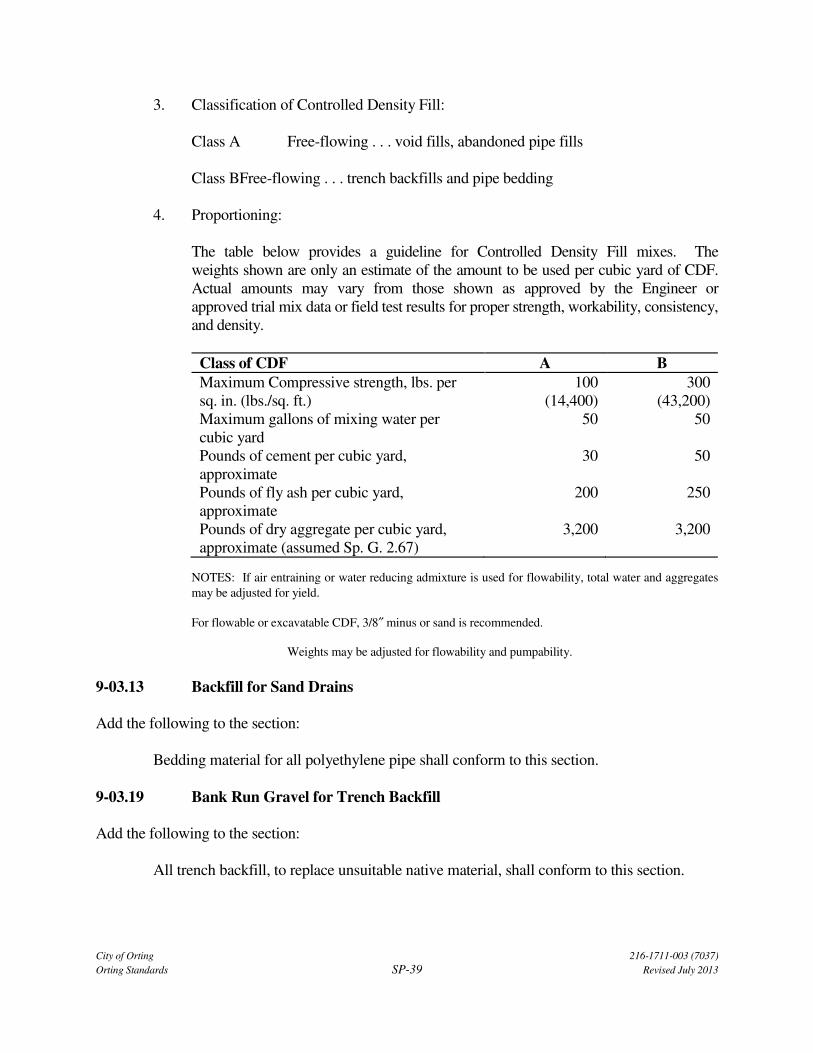
City of Orting 216-1711-003 (7037)
Orting Standards SP-39 Revised July 2013
3. Classification of Controlled Density Fill:
Class A Free-flowing . . . void fills, abandoned pipe fills
Class BFree-flowing . . . trench backfills and pipe bedding
4. Proportioning:
The table below provides a guideline for Controlled Density Fill mixes. The
weights shown are only an estimate of the amount to be used per cubic yard of CDF.
Actual amounts may vary from those shown as approved by the Engineer or
approved trial mix data or field test results for proper strength, workability, consistency,
and density.
Class of CDF A B
Maximum Compressive strength, lbs. per
sq. in. (lbs./sq. ft.)
100
(14,400)
300
(43,200)
Maximum gallons of mixing water per
cubic yard
50 50
Pounds of cement per cubic yard,
approximate
30 50
Pounds of fly ash per cubic yard,
approximate
200 250
Pounds of dry aggregate per cubic yard,
approximate (assumed Sp. G. 2.67)
3,200 3,200
NOTES: If air entraining or water reducing admixture is used for flowability, total water and aggregates
may be adjusted for yield.
For flowable or excavatable CDF, 3/8″ minus or sand is recommended.
Weights may be adjusted for flowability and pumpability.
9-03.13 Backfill for Sand Drains
Add the following to the section:
Bedding material for all polyethylene pipe shall conform to this section.
9-03.19 Bank Run Gravel for Trench Backfill
Add the following to the section:
All trench backfill, to replace unsuitable native material, shall conform to this section.

City of Orting 216-1711-003 (7037)
Orting Standards SP-40 Revised July 2013
9-05 DRAINAGE STRUCTURES, CULVERTS, AND CONDUITS
9-05.12 PVC Sewer Pipe
Add the following to the second paragraph of this section:
PVC pipe shall conform to ASTM D 3034-SDR35.


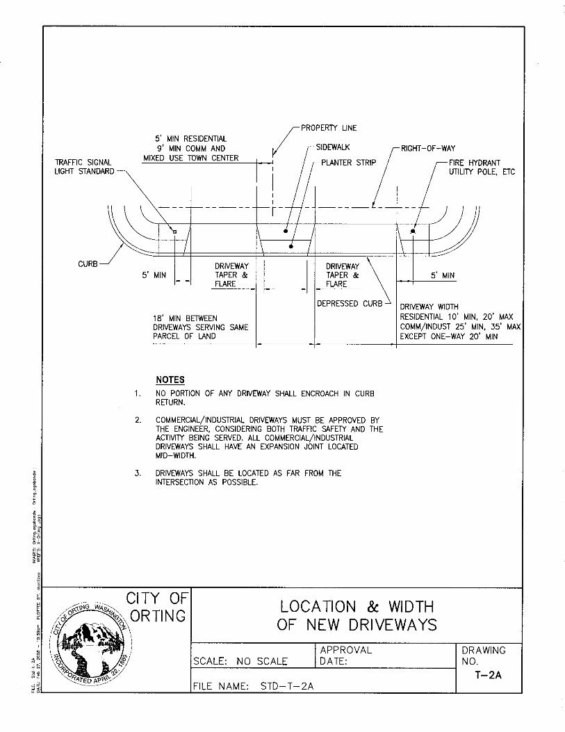

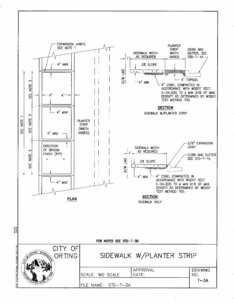
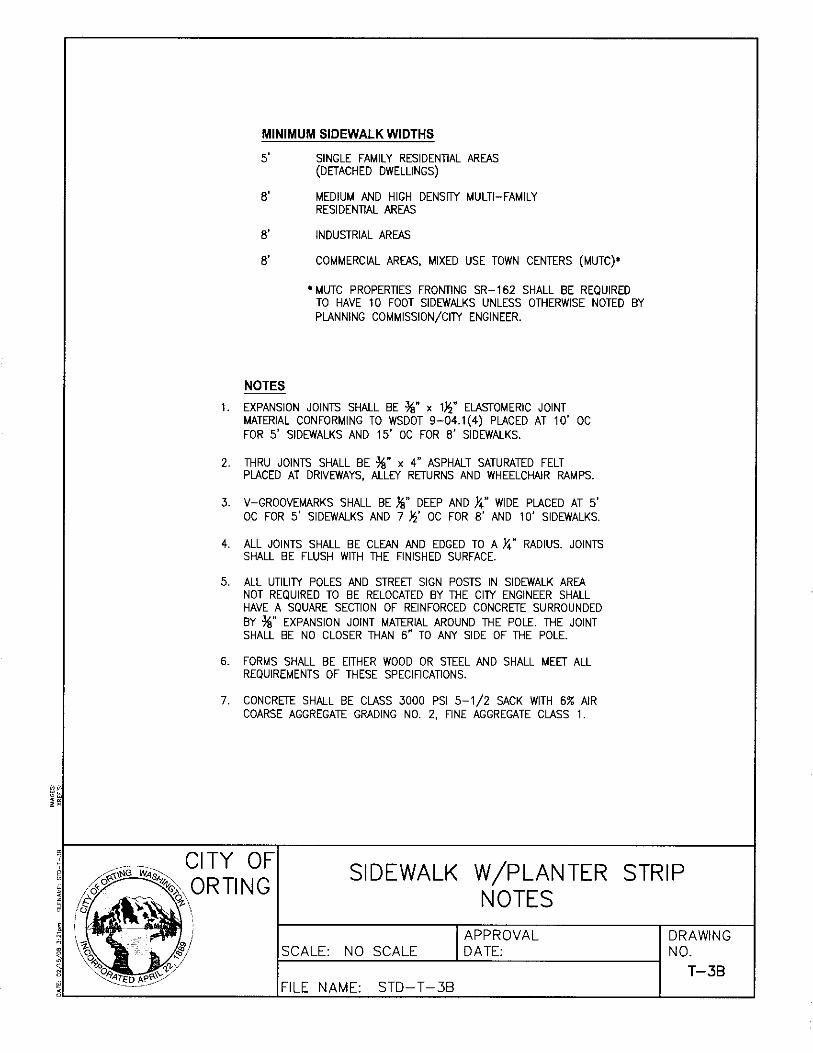
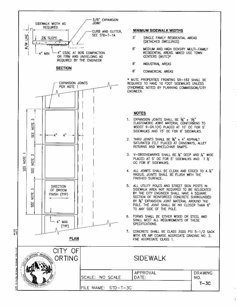
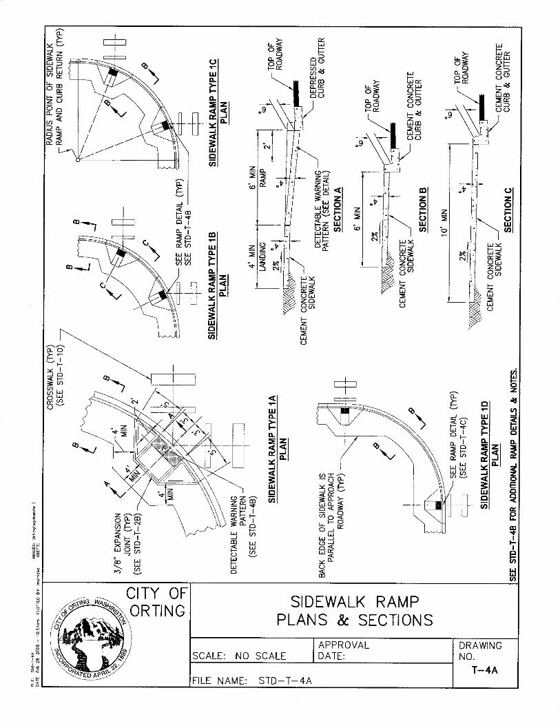
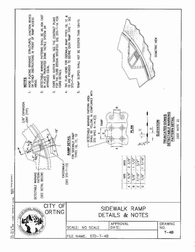
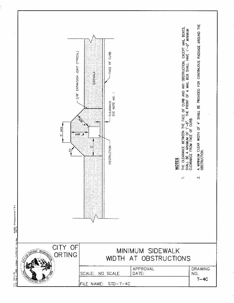

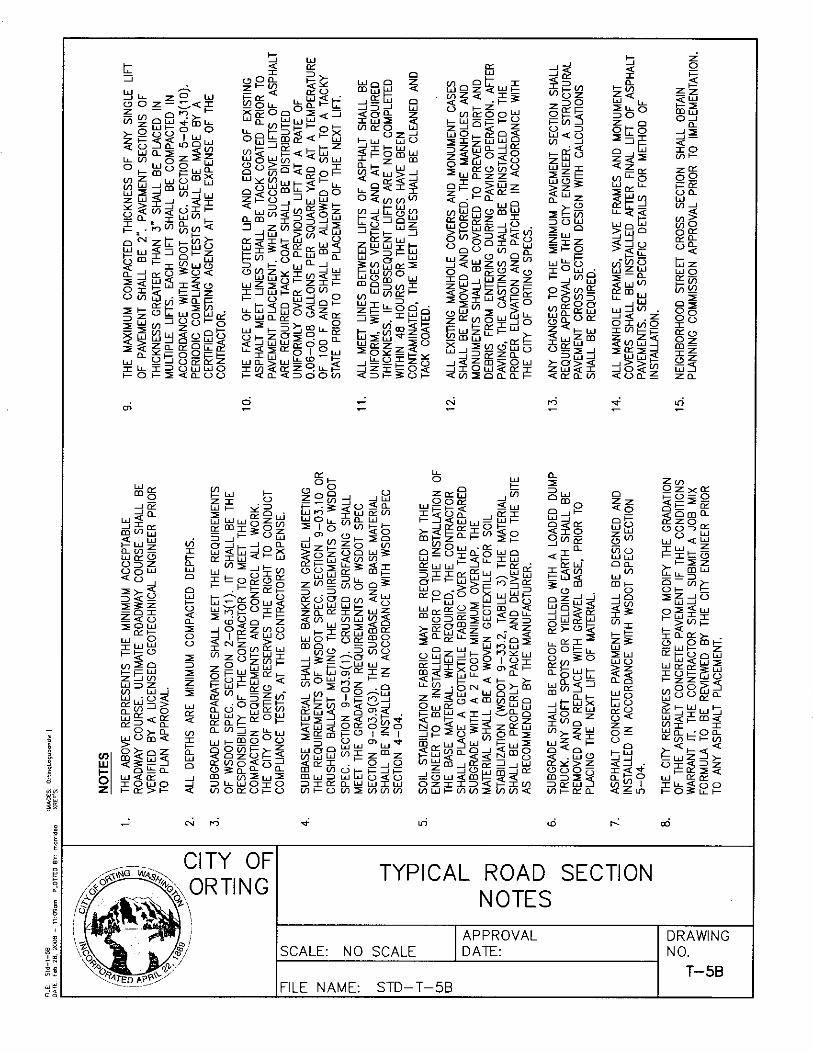

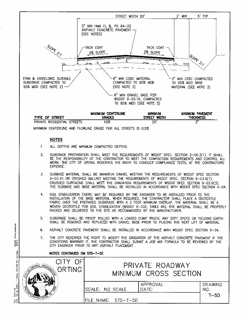
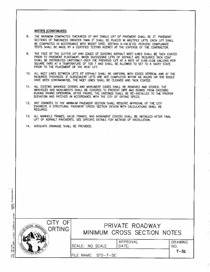


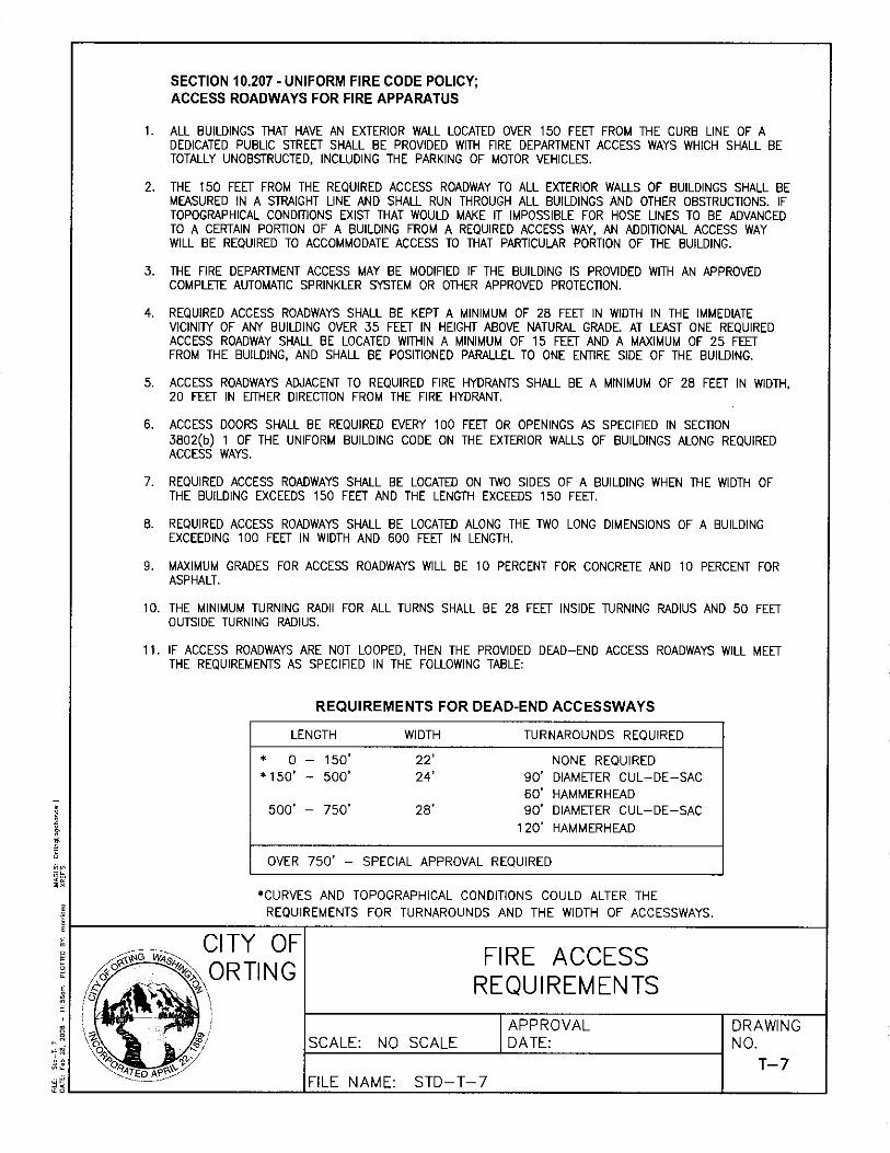
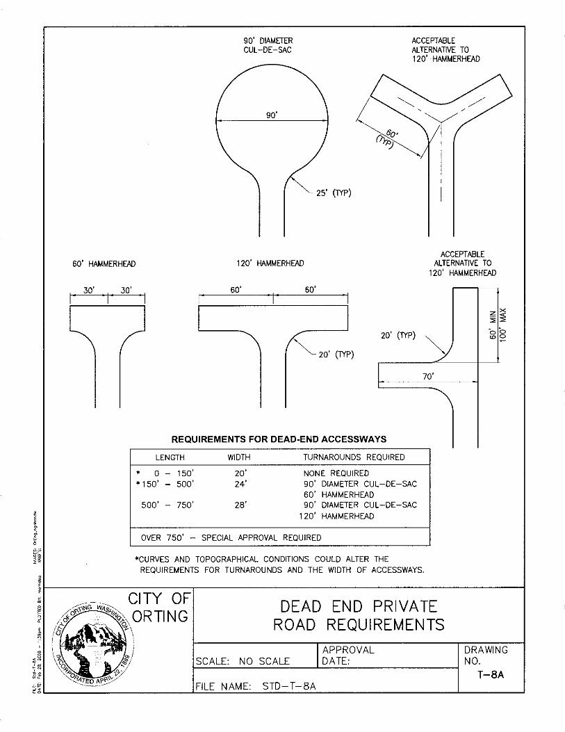
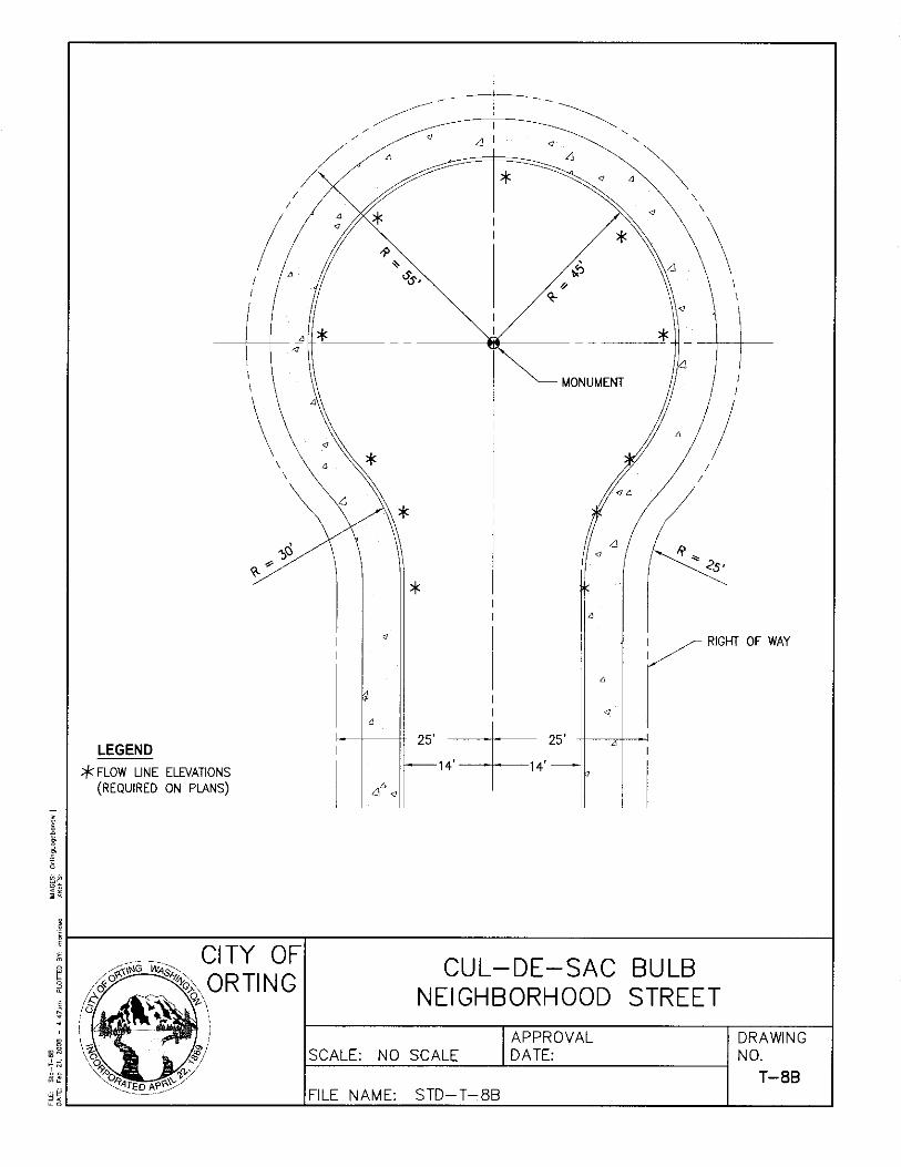
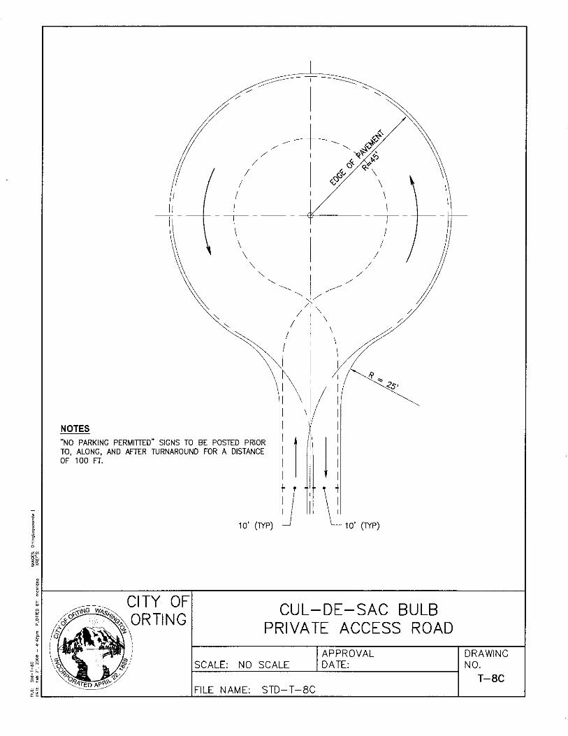
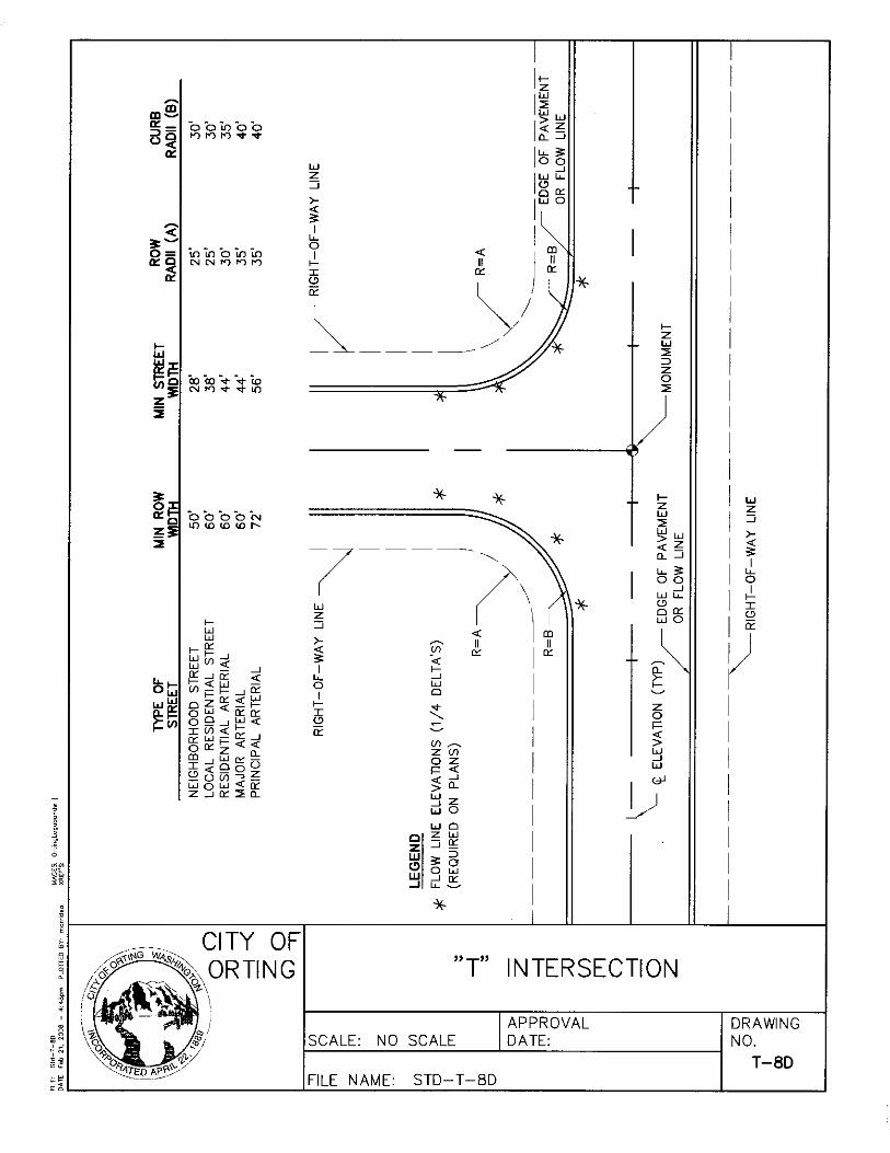
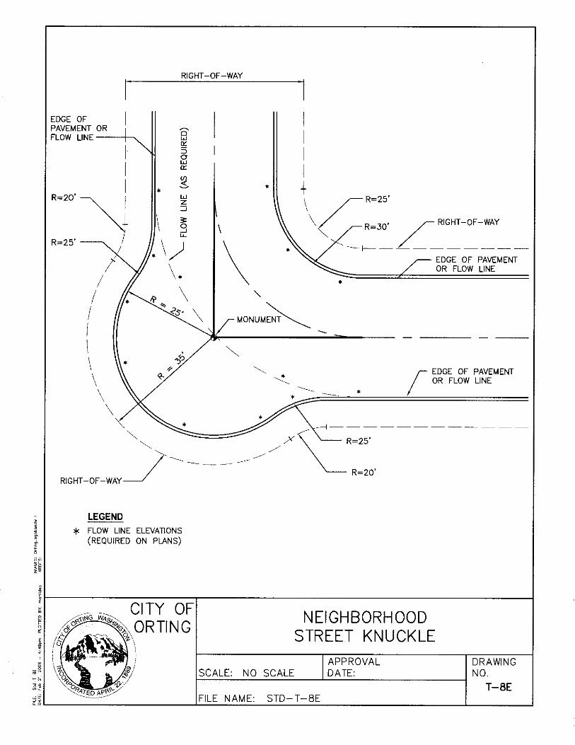
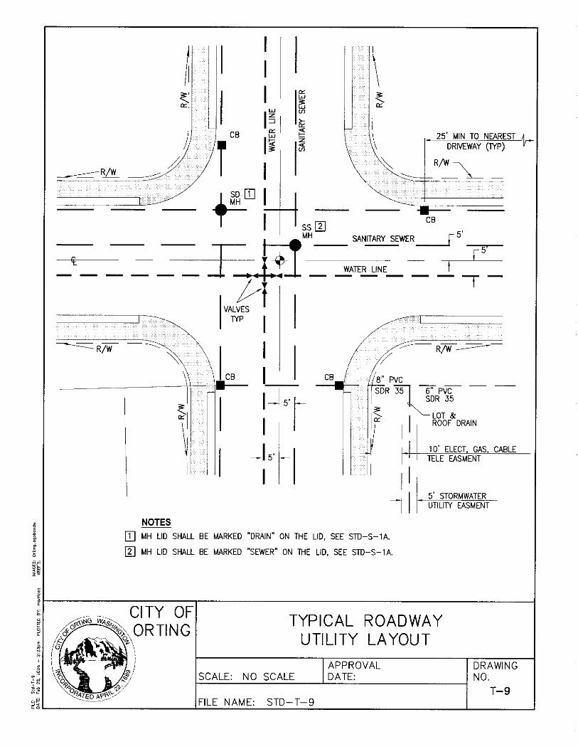
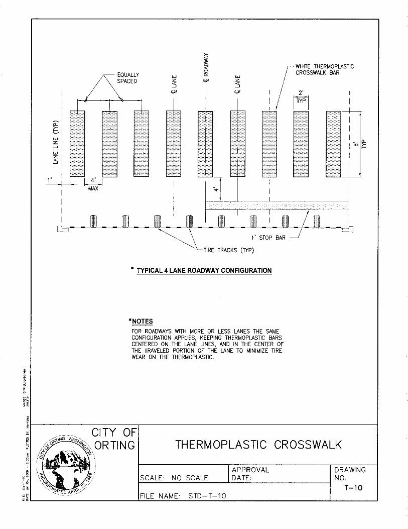
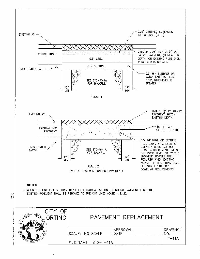
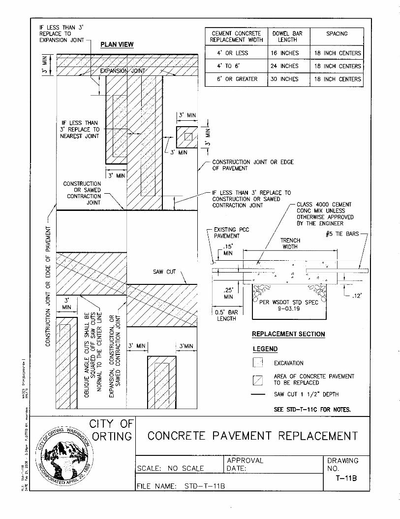
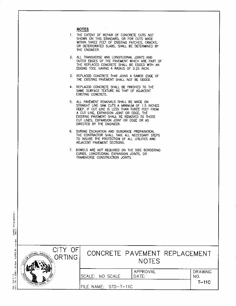
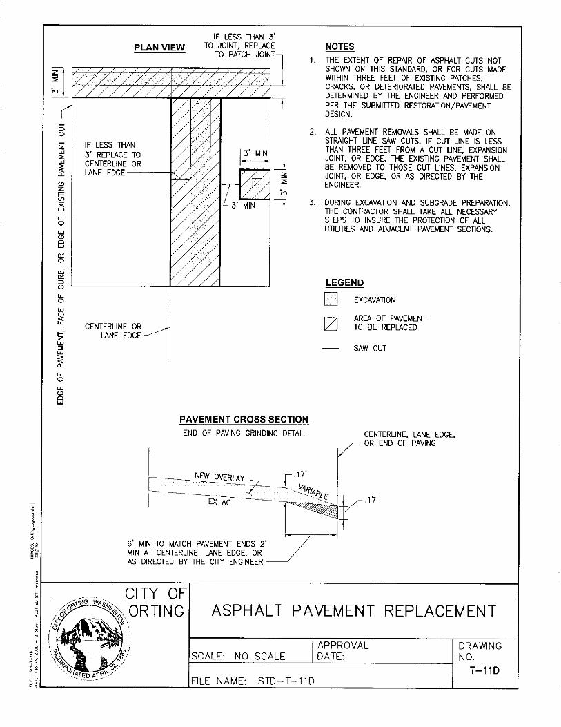
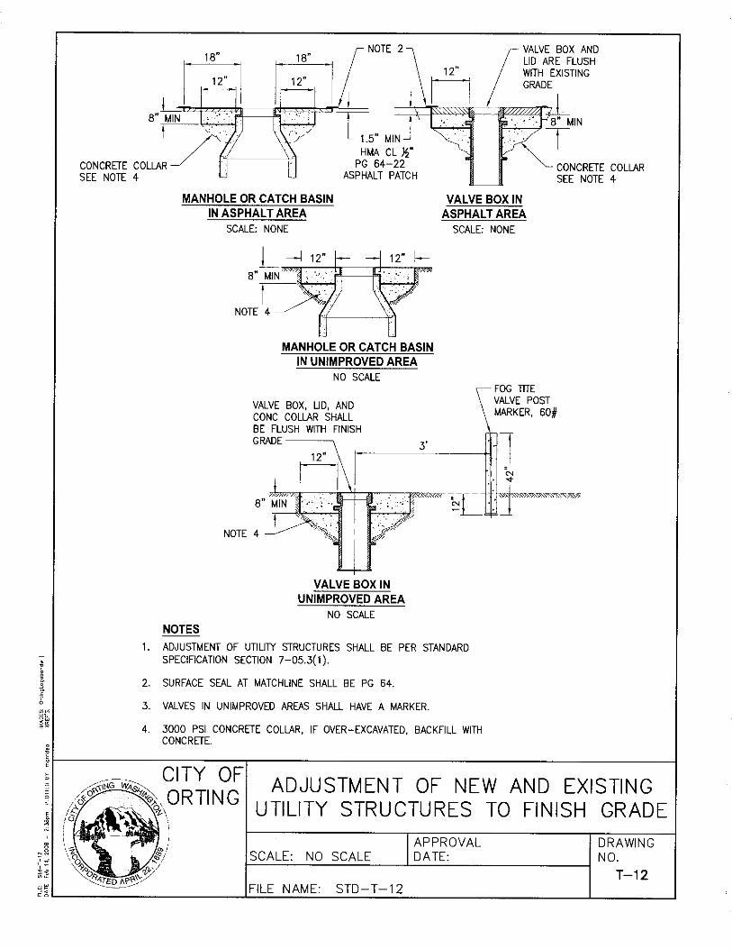

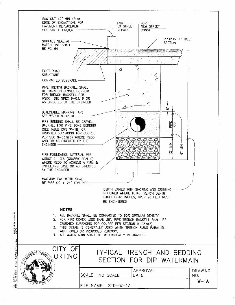
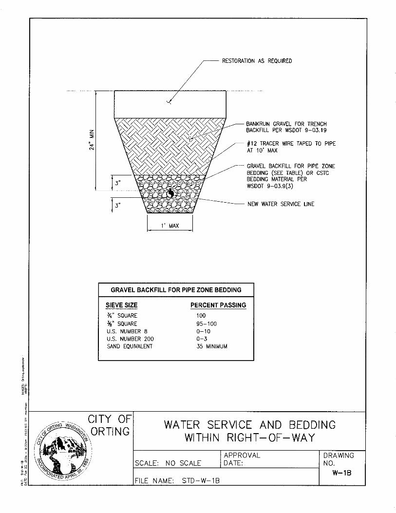
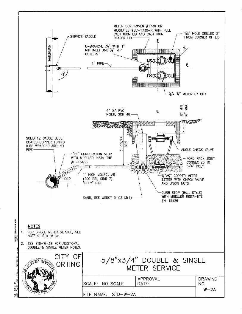
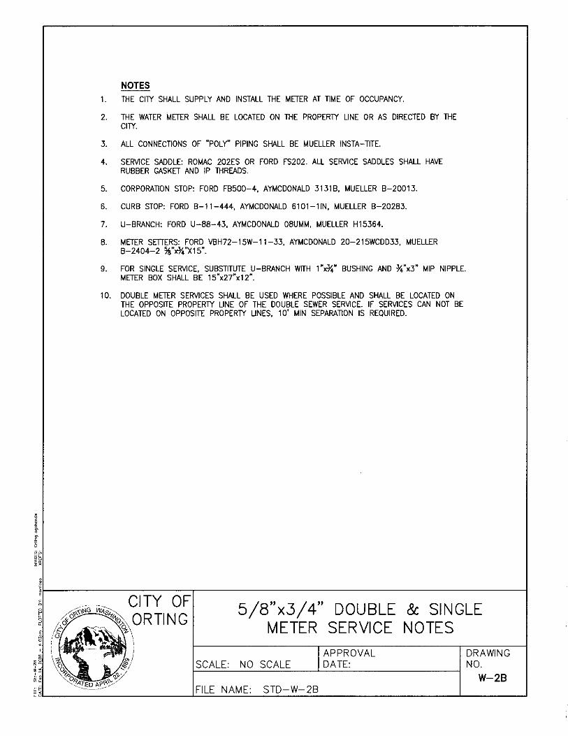

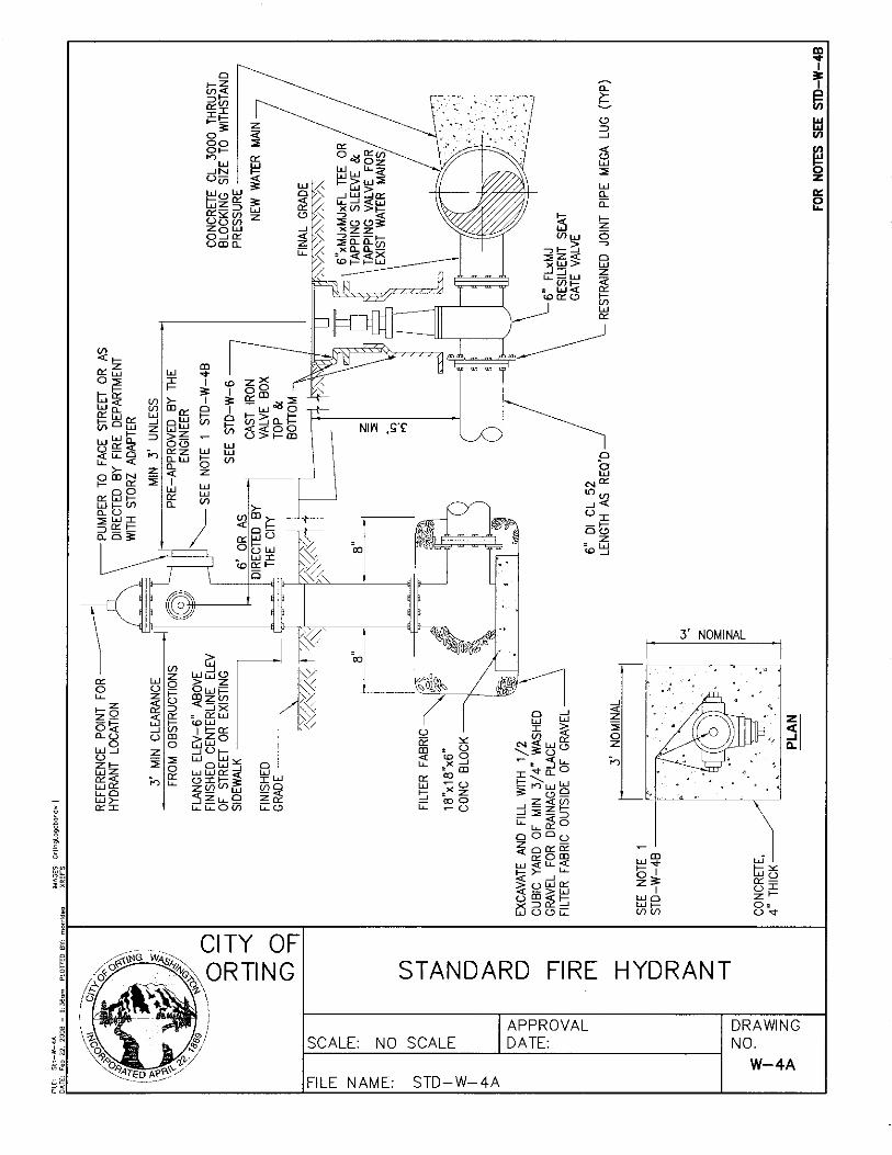
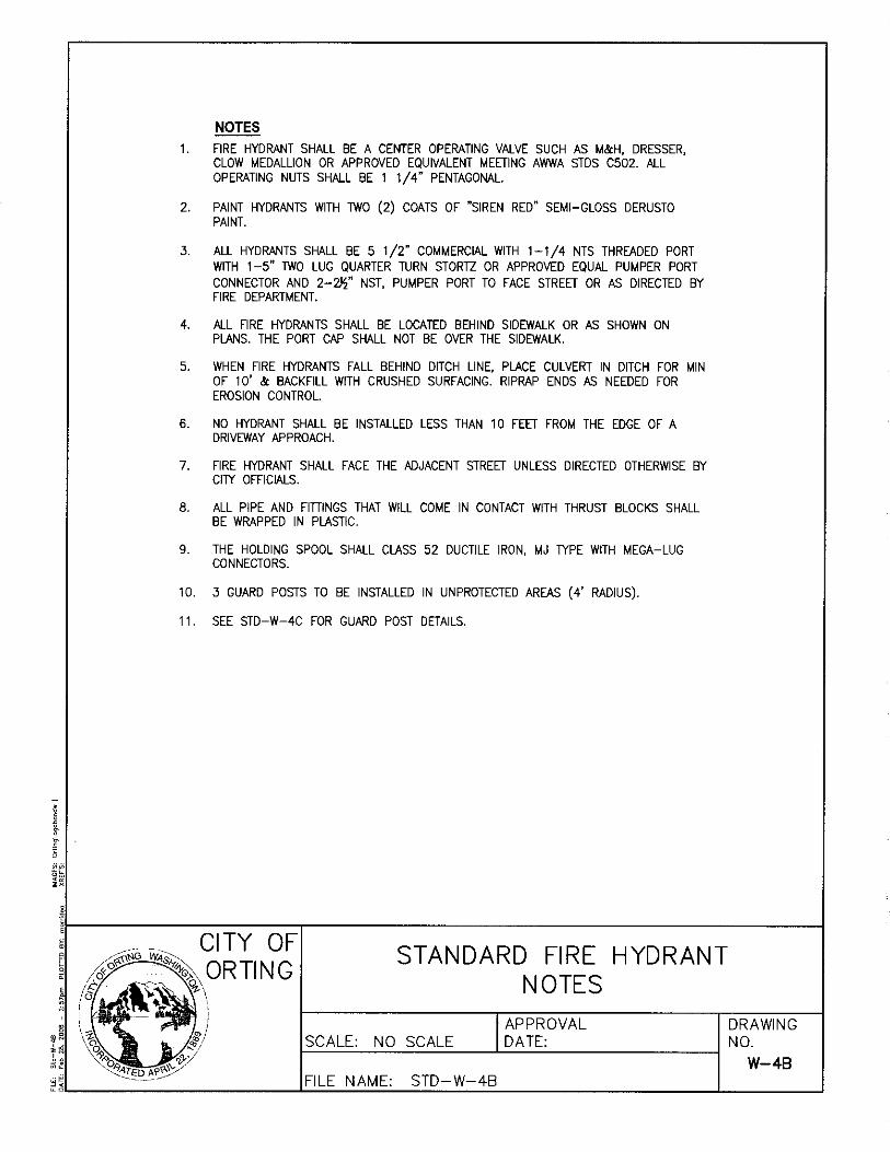


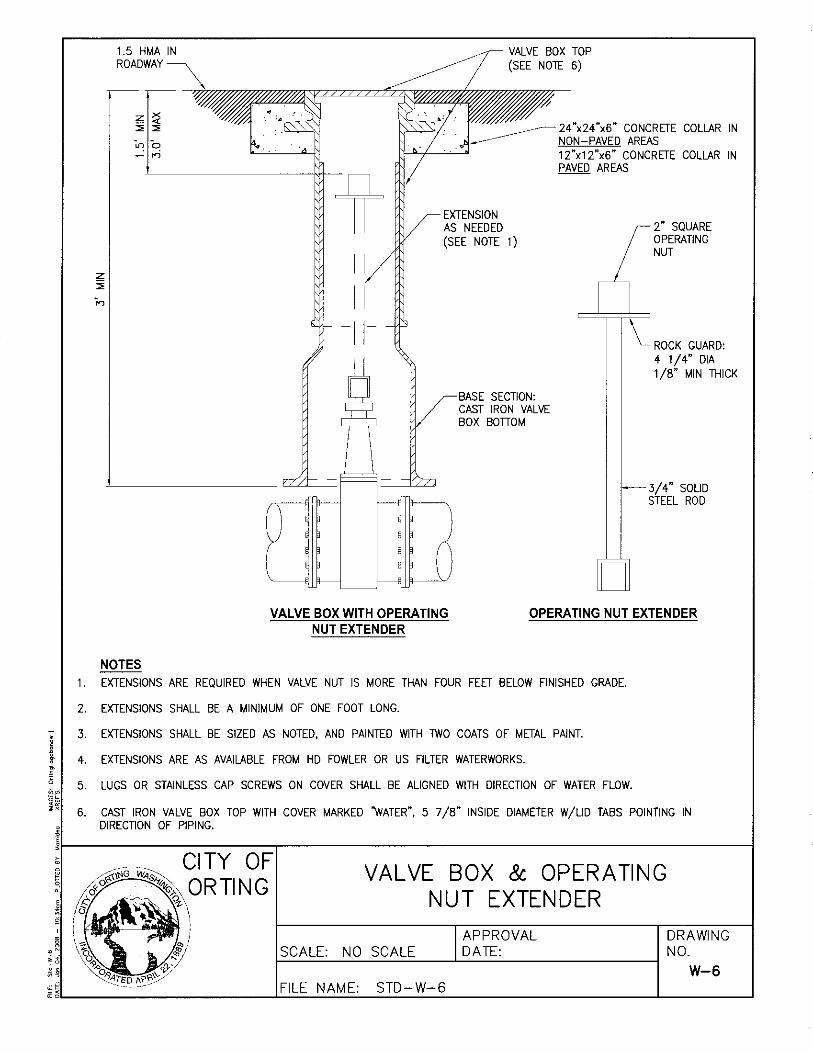

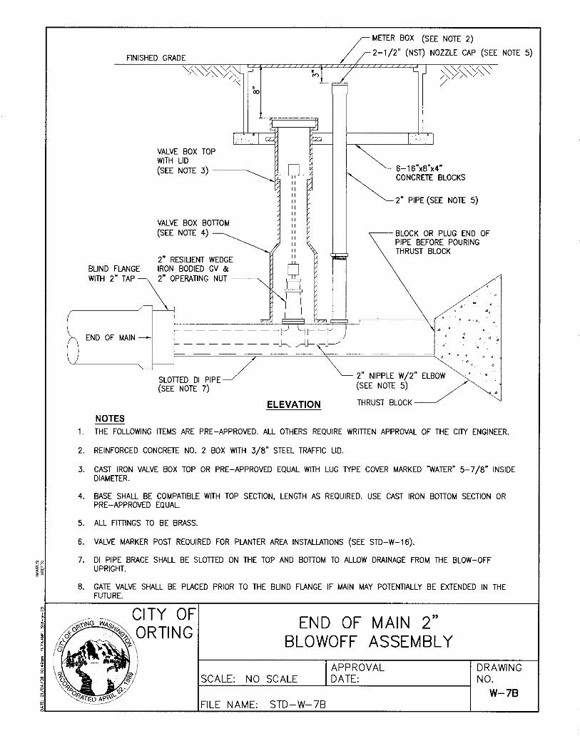
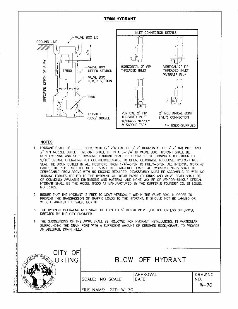
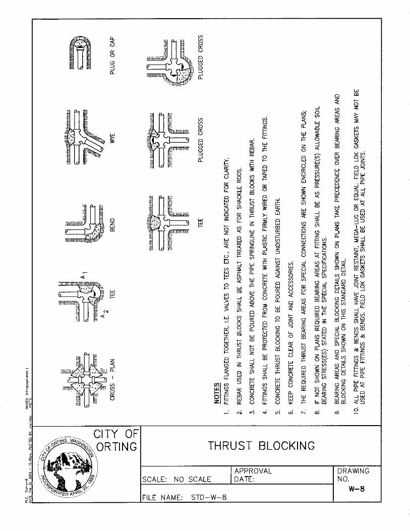
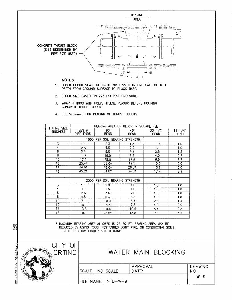

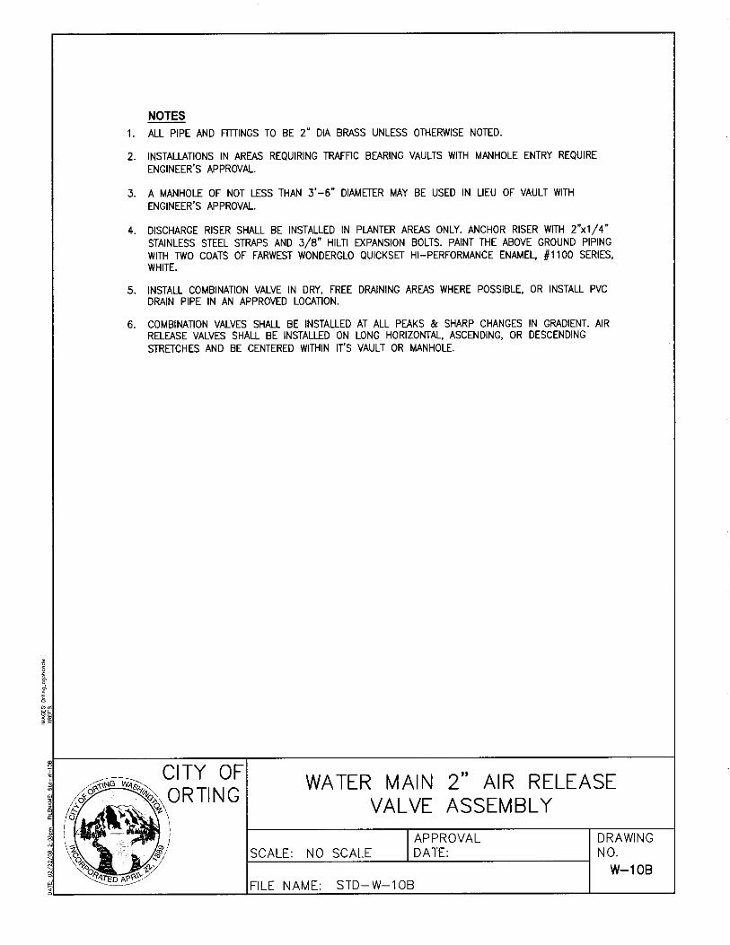
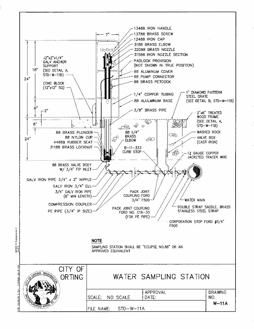
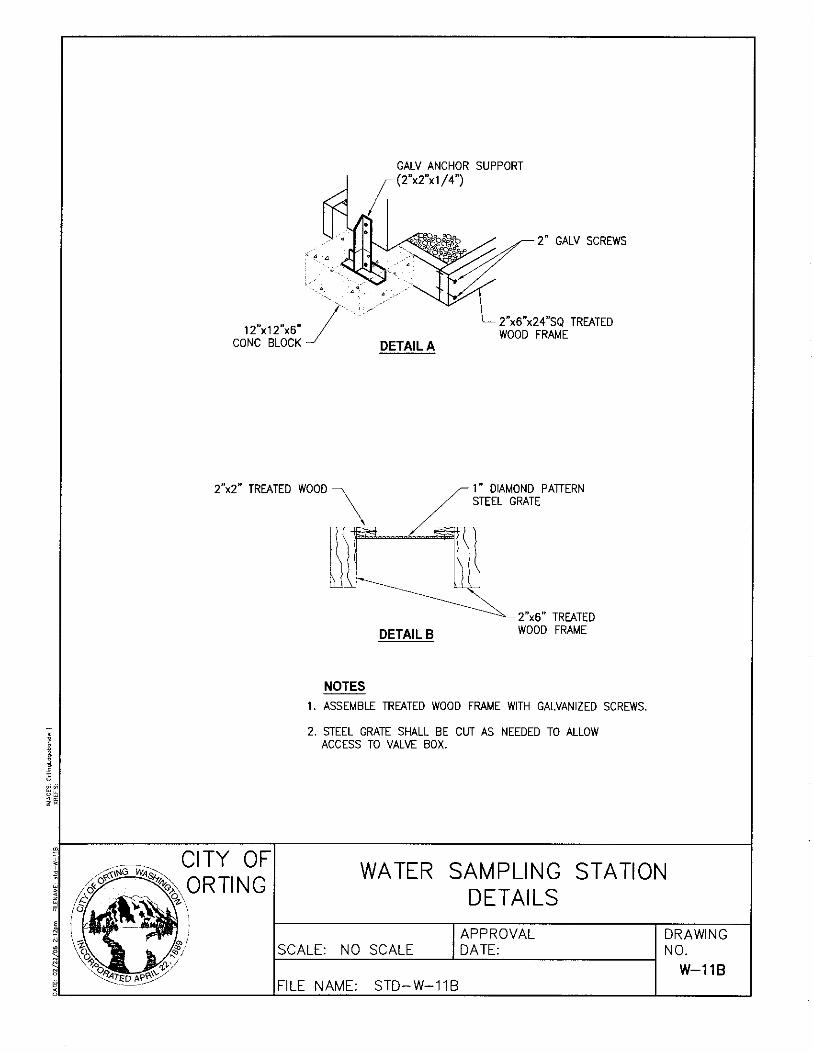
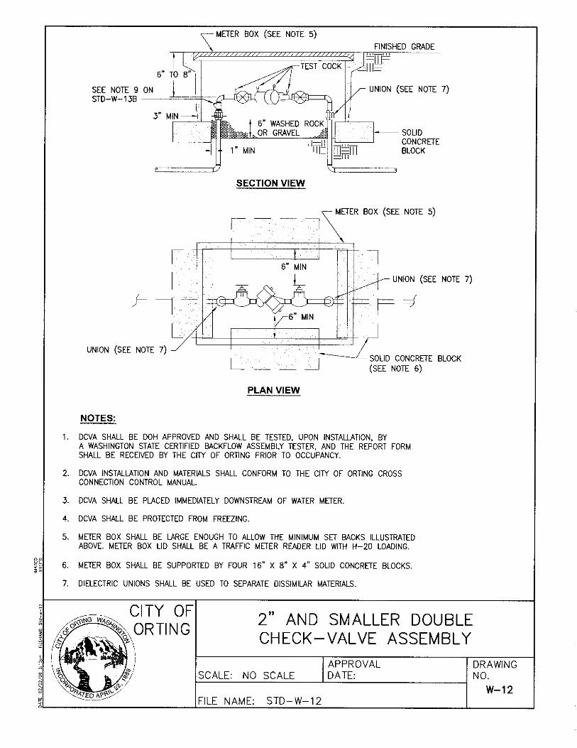
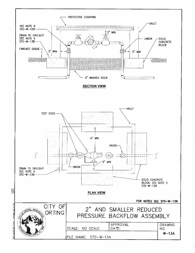
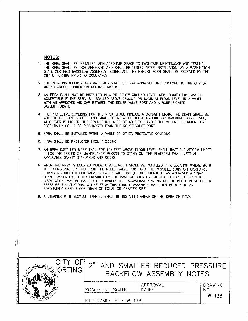
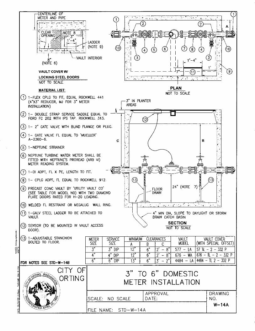
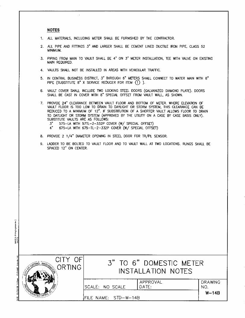
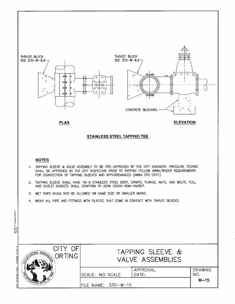
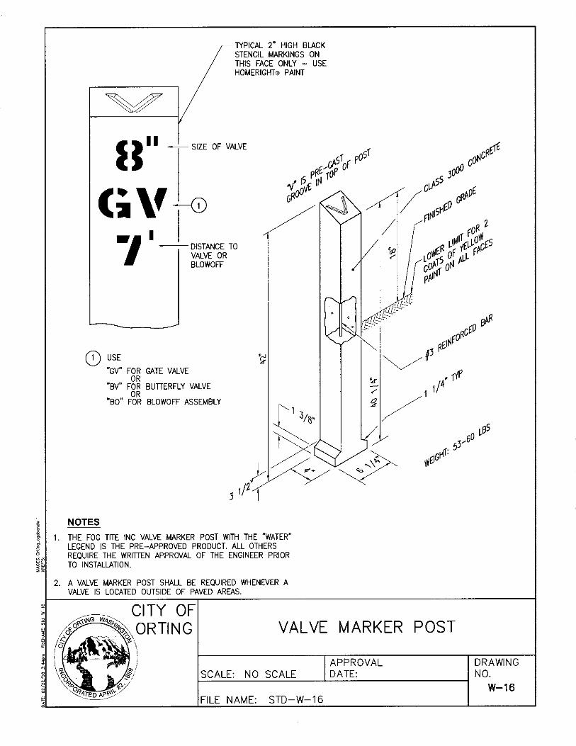
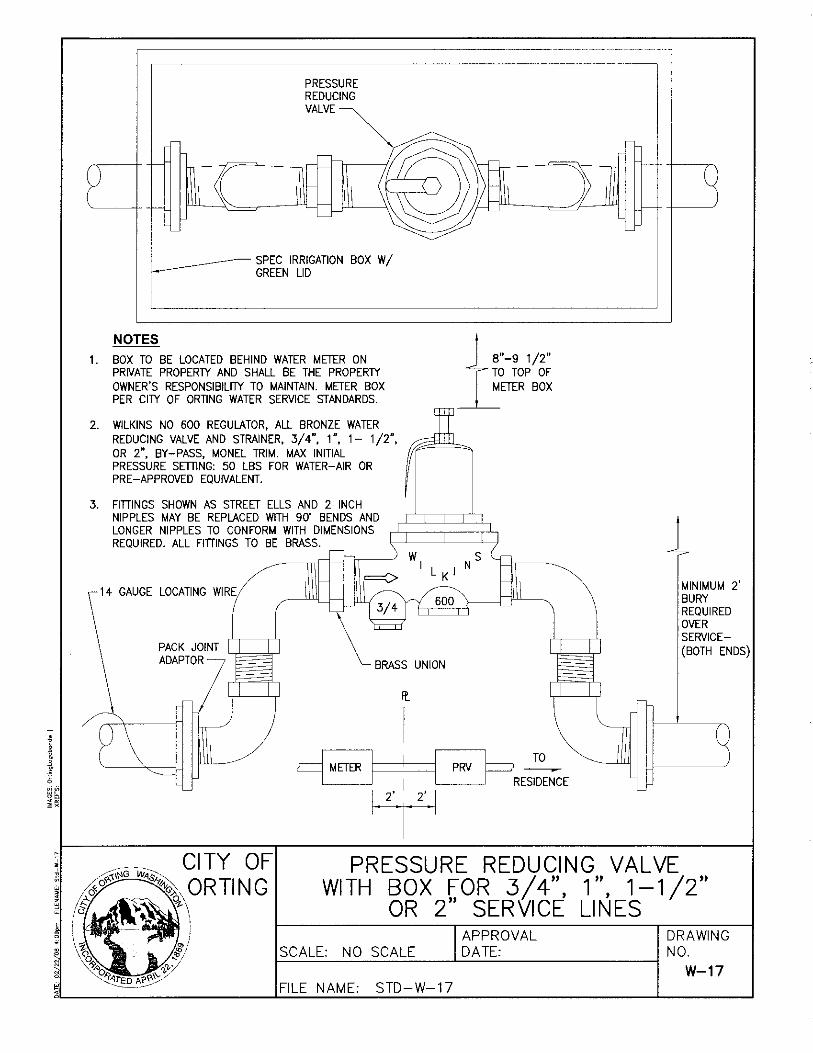


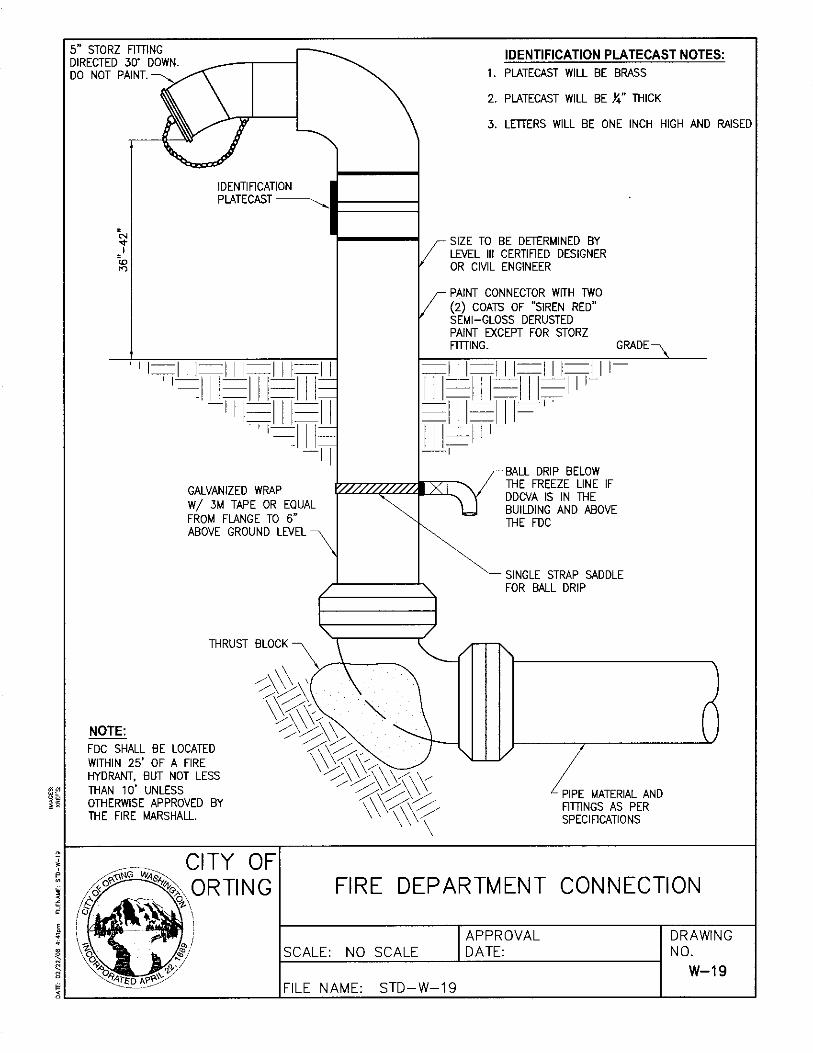

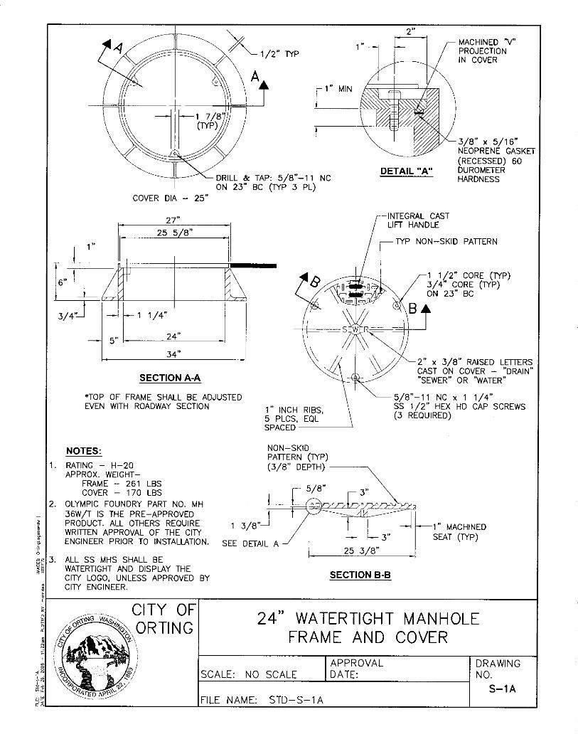
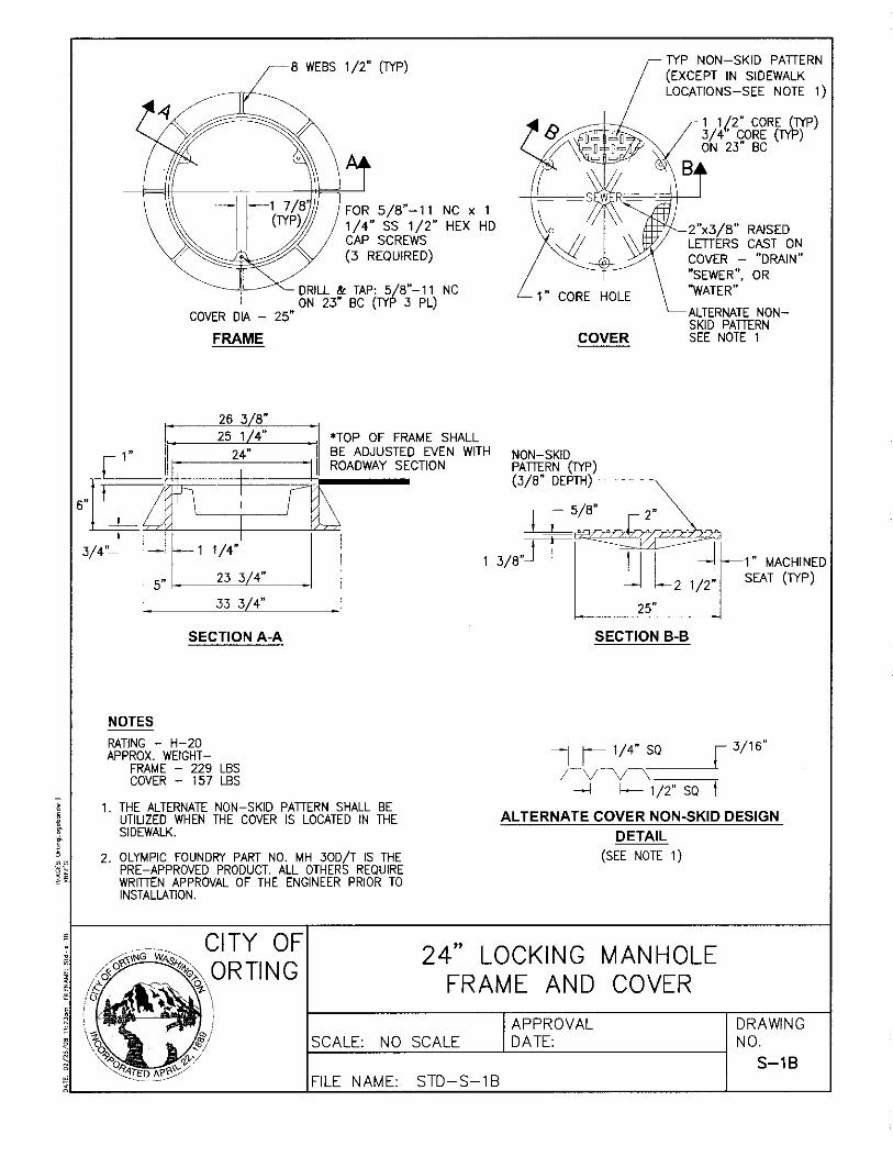
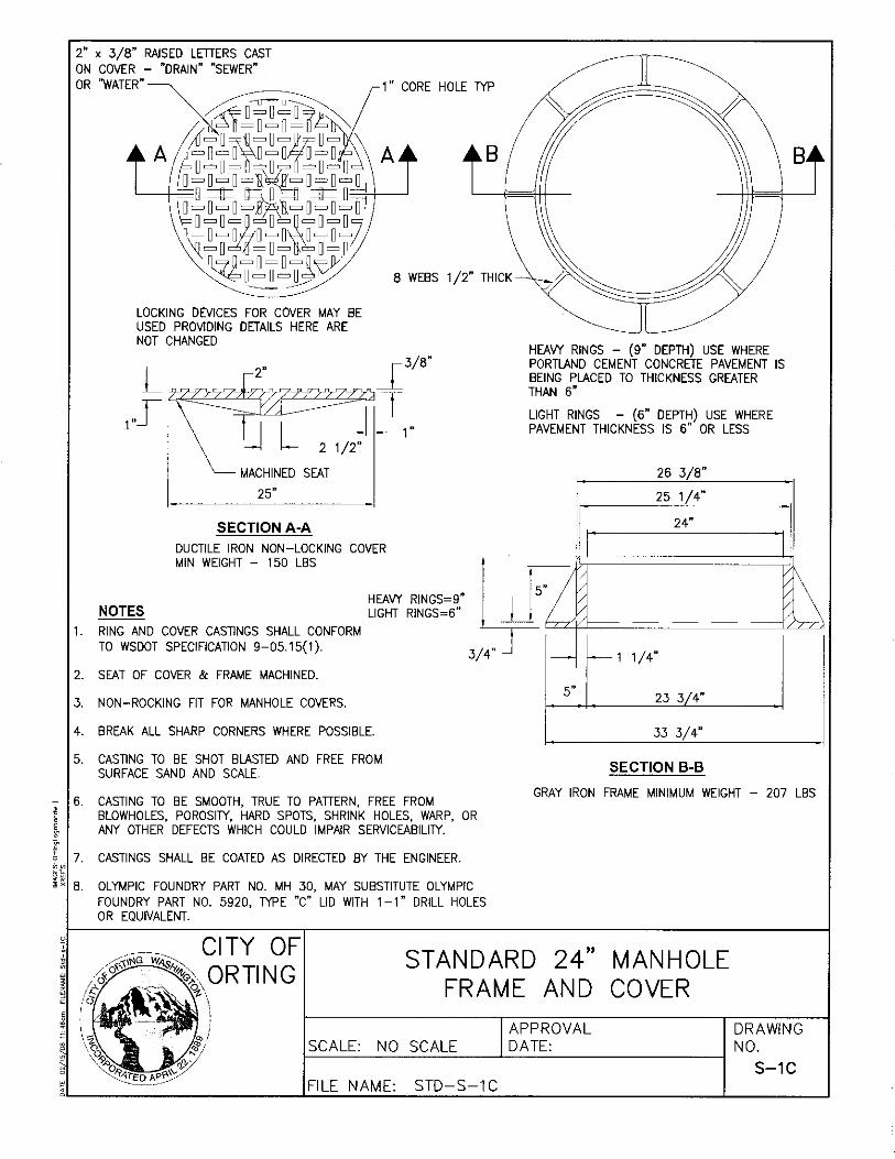

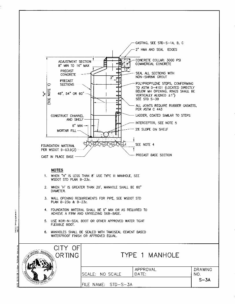
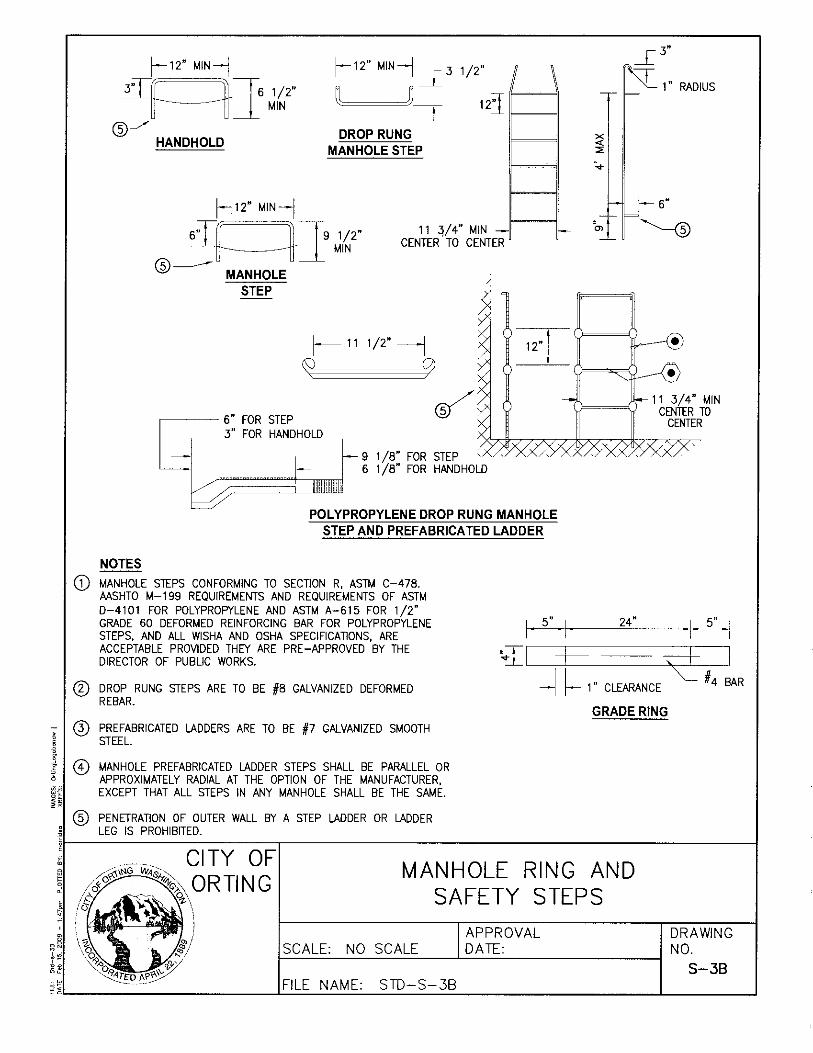
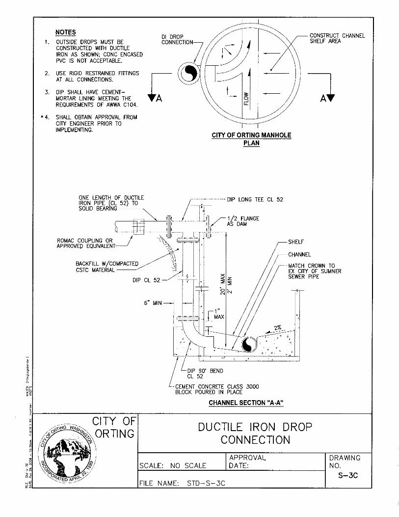


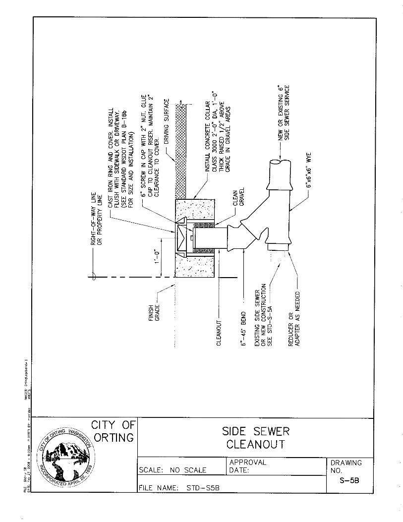
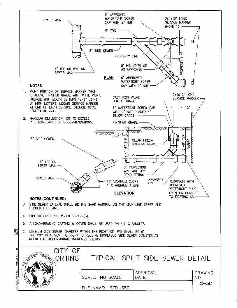
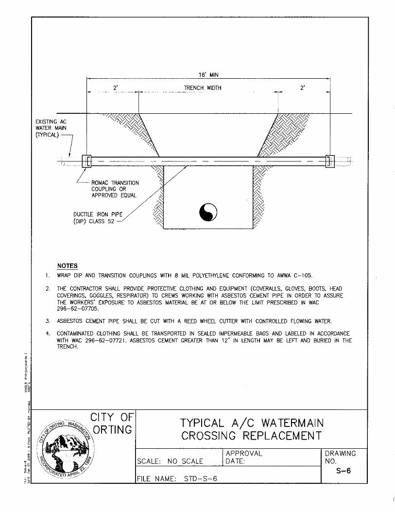

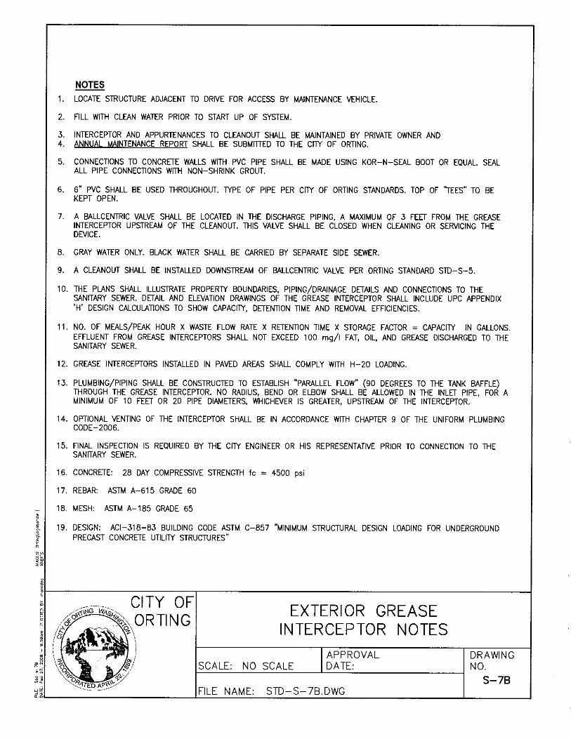
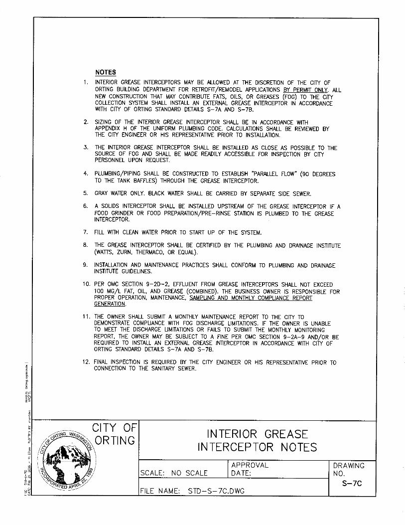
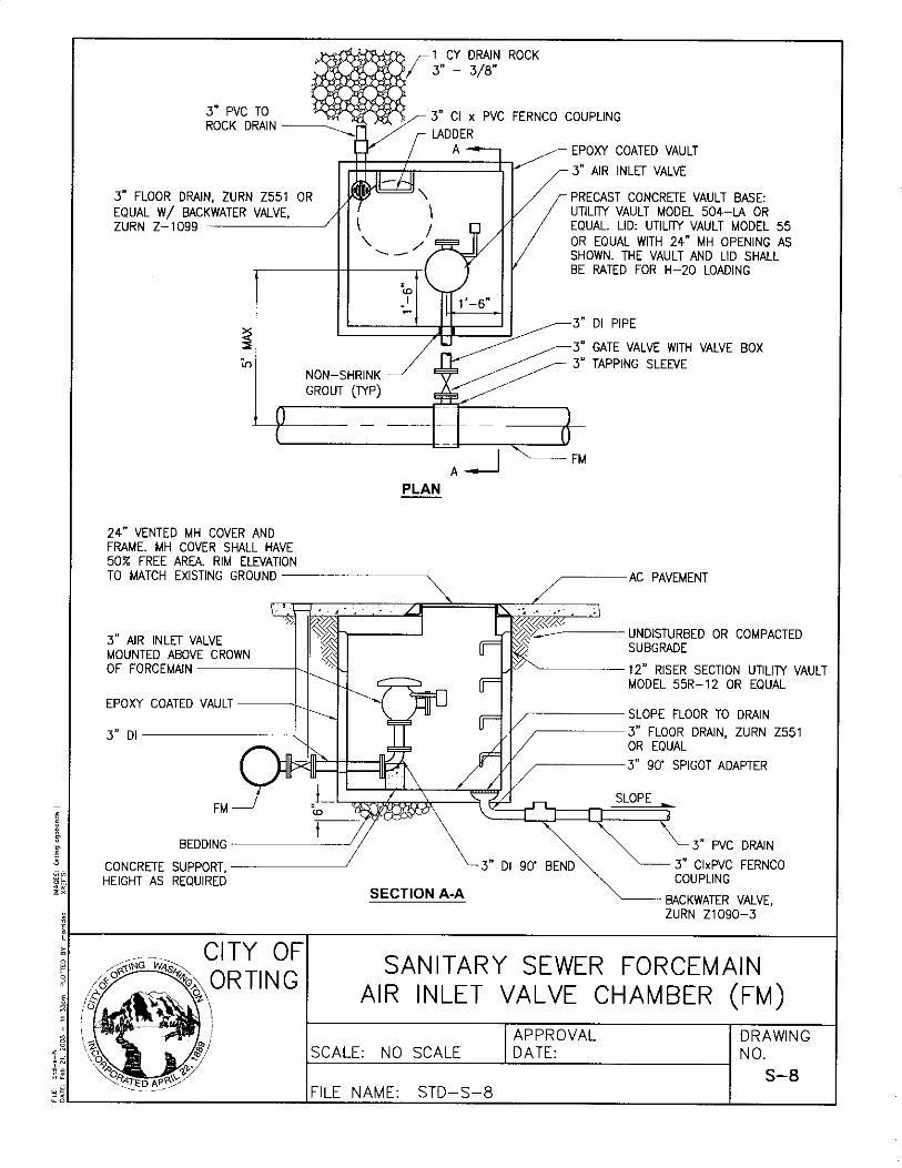
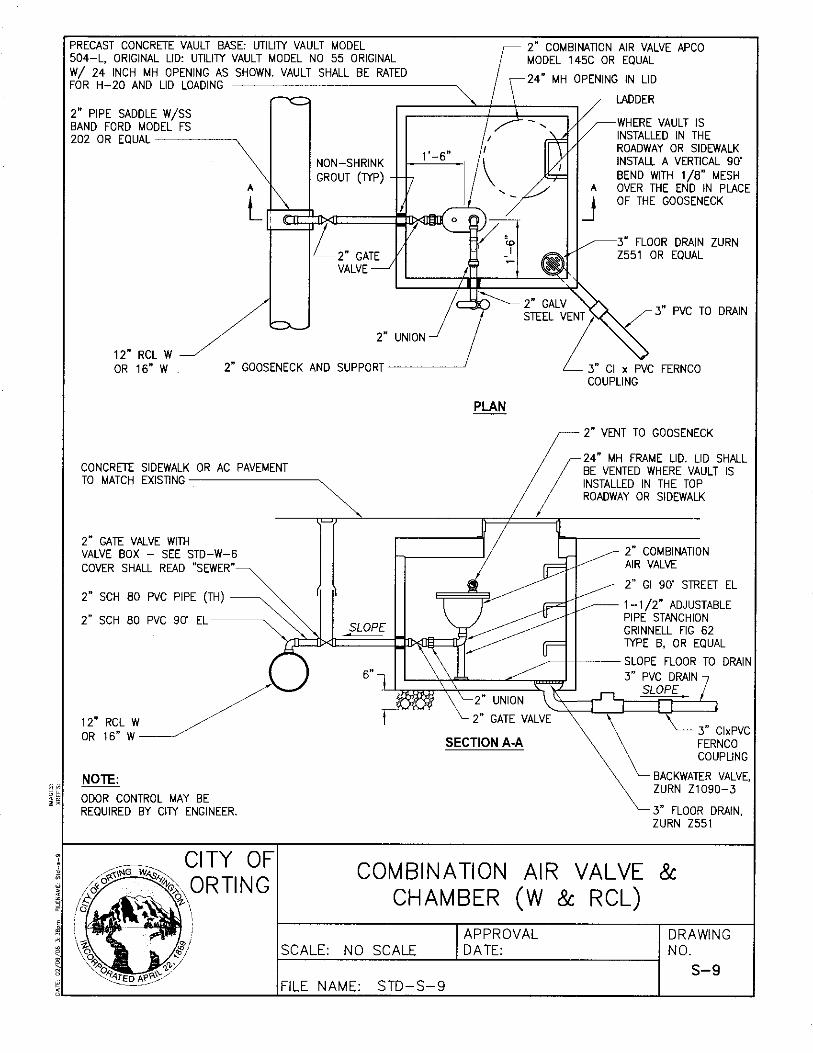


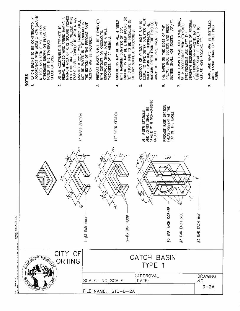
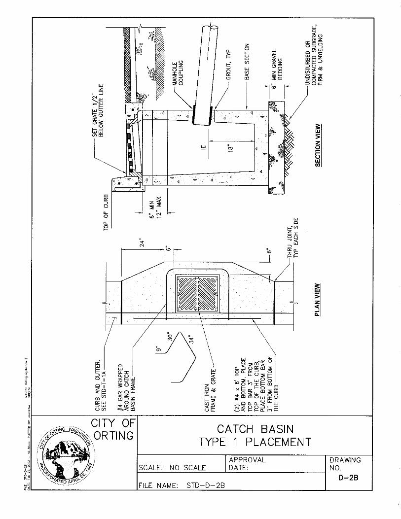
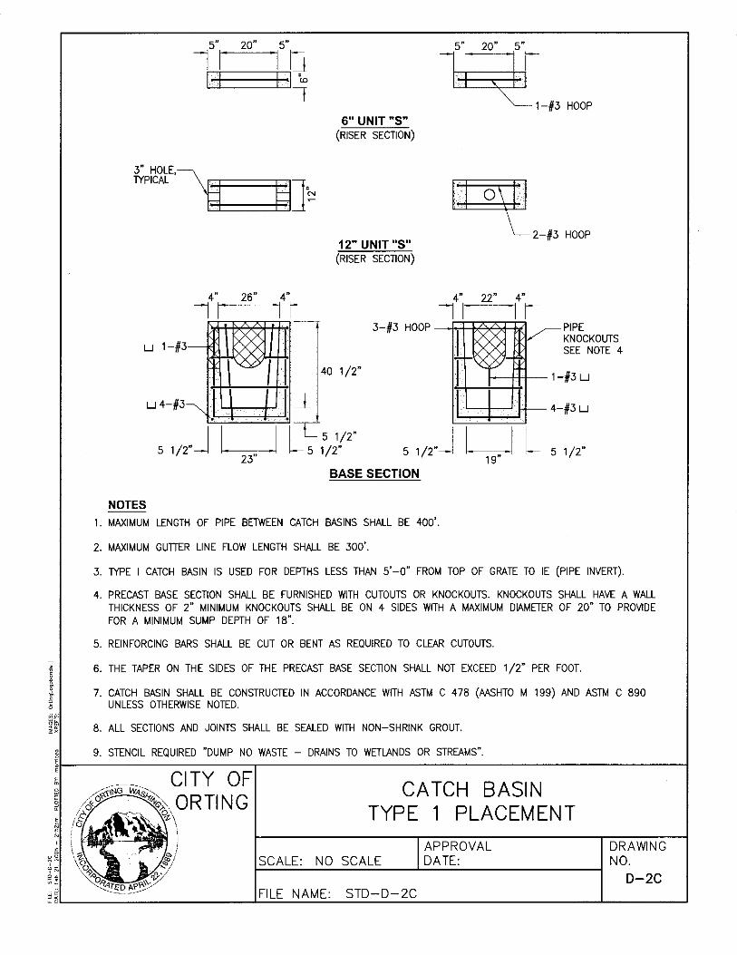
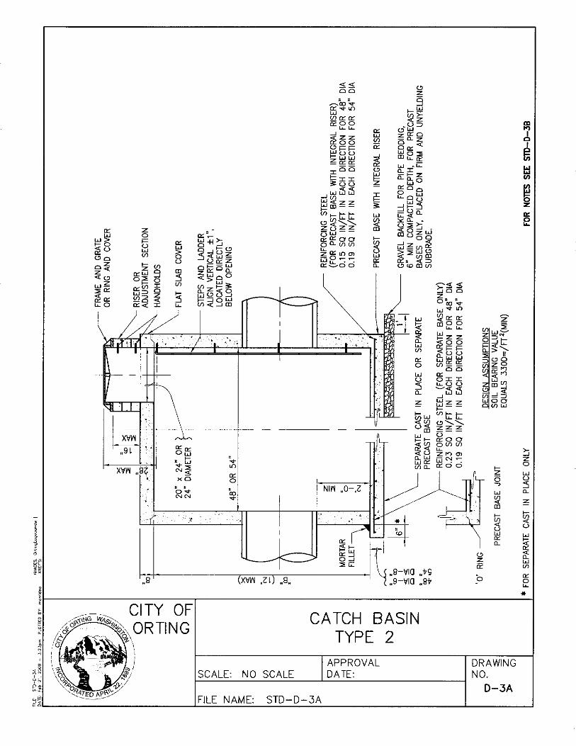
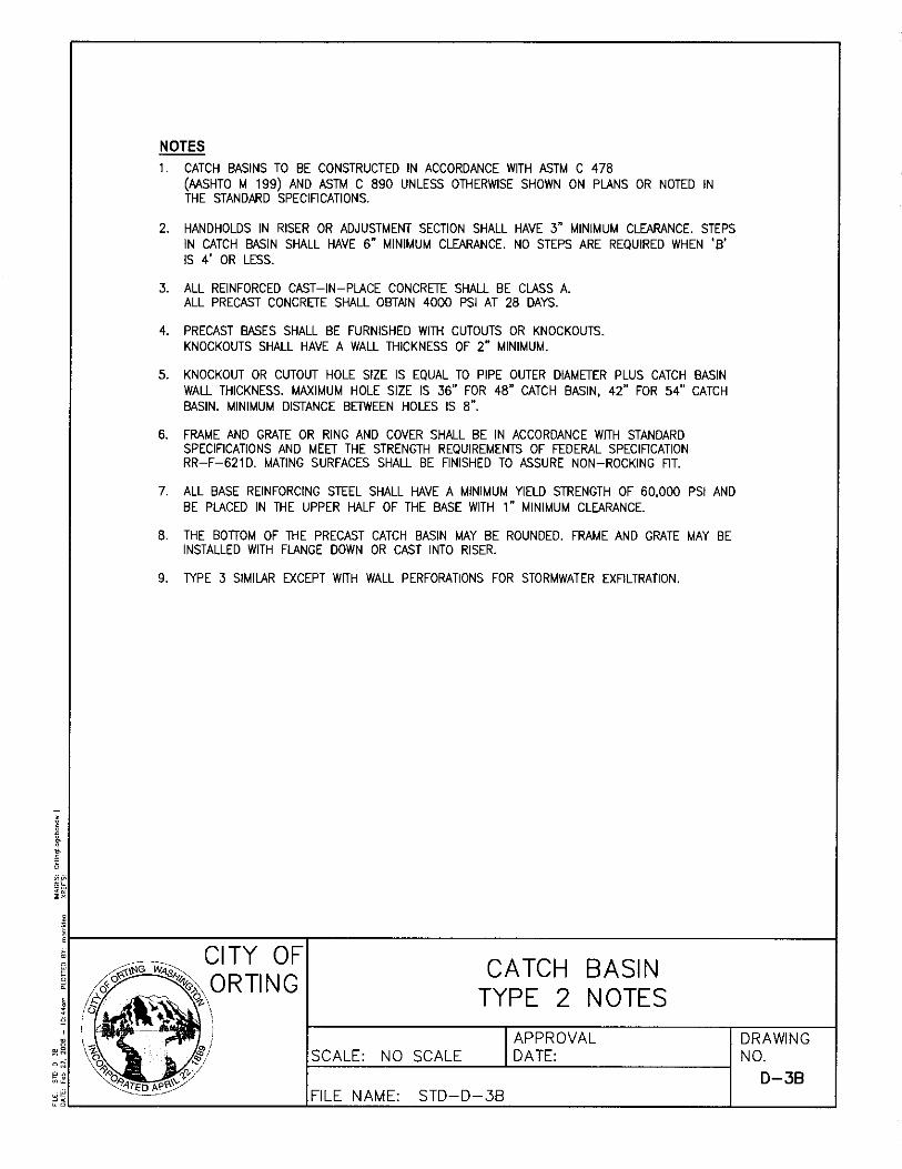

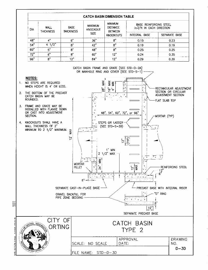
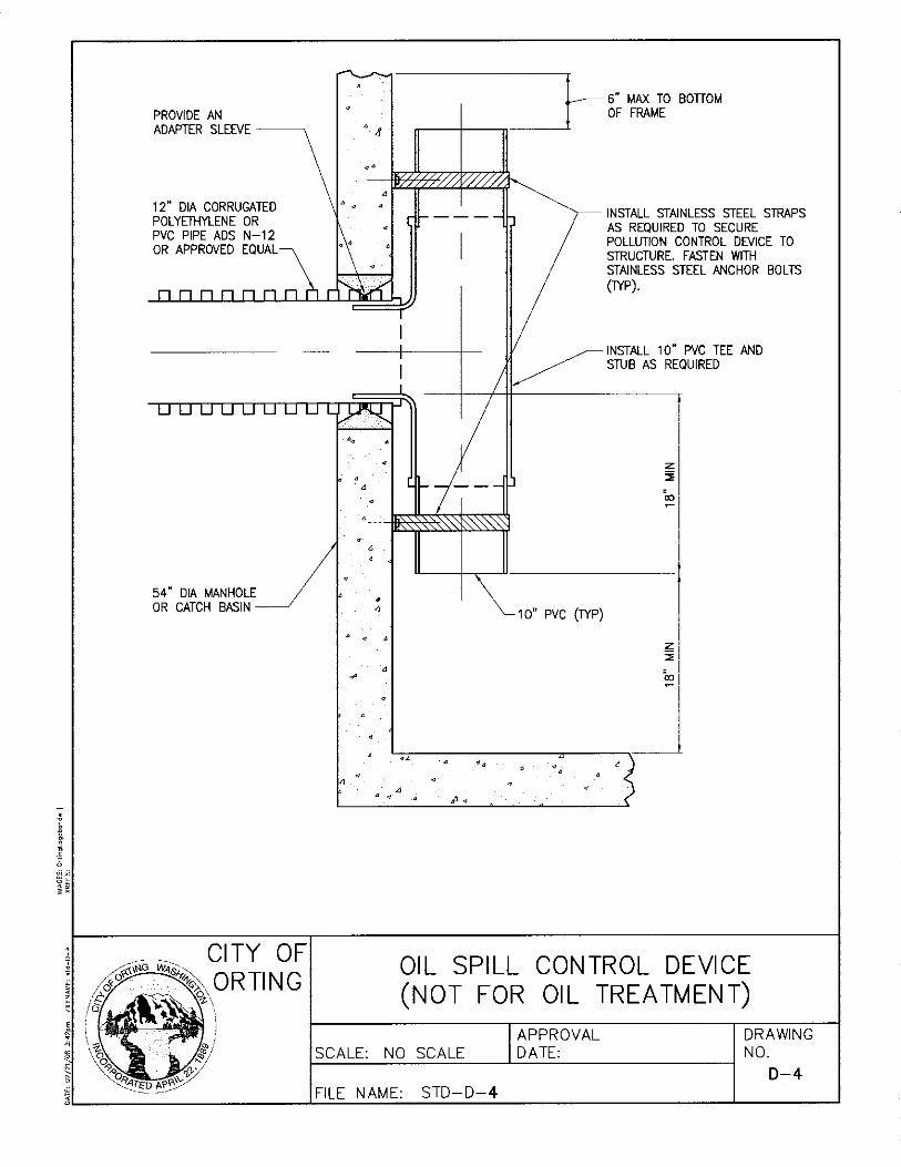
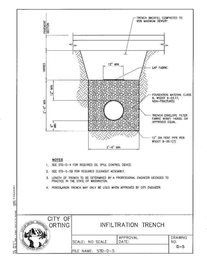
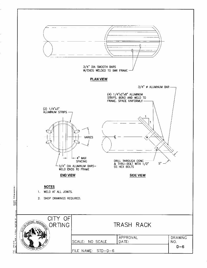


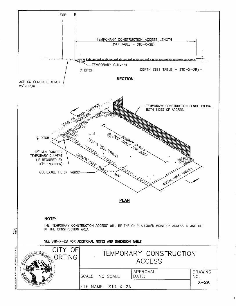

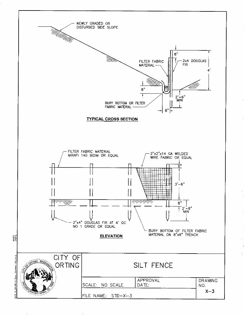


APPENDIX A
DEVELOPER CHECKLIST
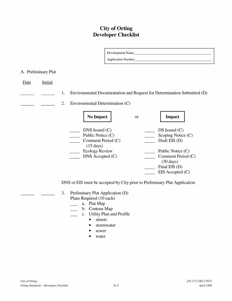
City of Orting 216-1711-003 (7037)
Orting Standards – Developer Checklist A-1 April 1999
City of Orting
Developer Checklist
Development Name
Application Number
A. Preliminary Plat
Date Initial
1. Environmental Documentation and Request for Determination Submitted (D)
2. Environmental Determination (C)
No Impact or Impact
DNS Issued (C) DS Issued (C)
Public Notice (C) Scoping Notice (C)
Comment Period (C)
(15 days)
Draft EIS (D)
Ecology Review Public Notice (C)
DNS Accepted (C) Comment Period (C)
(30 days)
Final EIS (D)
EIS Accepted (C)
DNS or EIS must be accepted by City prior to Preliminary Plat Application.
3. Preliminary Plat Application (D)
Plans Required (10 each)
a. Plat Map
b. Contour Map
c. Utility Plan and Profile
• streets
• stormwater
• sewer
• water

City of Orting 216-1711-003 (7037)
Orting Standards – Developer Checklist A-2 April 1999
Date Initial 4. City Review and Comment (C)
• Mayor • City Administrator • Fire Chief • Engineer • Building Inspector • Utility Superintendent • Schools
5. Planning Commission (C)
• Public hearing and determination 6. City Council (C)
• Public hearing and action on Planning Commission recommendation B. Improvements 1. Developer Extension Agreement (D and C) 2. Review Deposit Paid (D) 3. Submit Final Construction Plans (D) 4. Review and Approval (C)
• City Engineer • Fire Chief • Utility Superintendent • City Council
5. Bond Posted (D) 6. Inspection Fee Paid (D) 7. Contractor Approval (C) 8. Complete Construction (D) 9. Final Charges and Fees Paid (D) 10. Latecomers Agreement Executed (if necessary) (C) 11. Construction Acceptance (C)
• Engineer Approval • Council Approval
12. As-built Mylars (D)
• Engineer Approval • Council Approval • AutoCAD Files to City
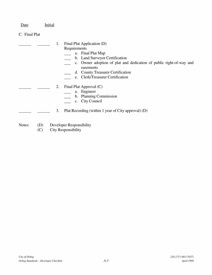
City of Orting 216-1711-003 (7037)
Orting Standards – Developer Checklist A-3 April 1999
Date Initial
C. Final Plat
1. Final Plat Application (D)
Requirements
a. Final Plat Map
b. Land Surveyor Certification
c. Owner adoption of plat and dedication of public right-of-way and
easements
d. County Treasurer Certification
e. Clerk/Treasurer Certification
2. Final Plat Approval (C)
a. Engineer
b. Planning Commission
c. City Council
3. Plat Recording (within 1 year of City approval) (D)
Notes: (D) Developer Responsibility
(C) City Responsibility

APPENDIX B
DEVELOPER EXTENSION AGREEMENT
City of Orting 11-1711-02
Orting Standards – Extension Agreement B-1 July2004
CITY OF ORTING
UTILITY EXTENSION AGREEMENT
The undersigned, hereinafter referred to as DEVELOPER, hereby makes application to the City of Orting,
hereinafter referred to as CITY, for permission to construct and install an extension to the CITY's utility
and street system, on public right-of-way, and/or on easements which are subject to the approval of the
CITY and connect the same to the utility and street system of the CITY and makes the following
representation and agreements to wit:
I. Location
The proposed utility extension and streets shall be for the use and benefit of the property
hereinafter described, which property is owned by the DEVELOPER and/or other owners who are
contributing to the cost of said extension and construction; said other owners join in this
application and referred to as “additional owners”; that said property is described as follows:
Description of Property
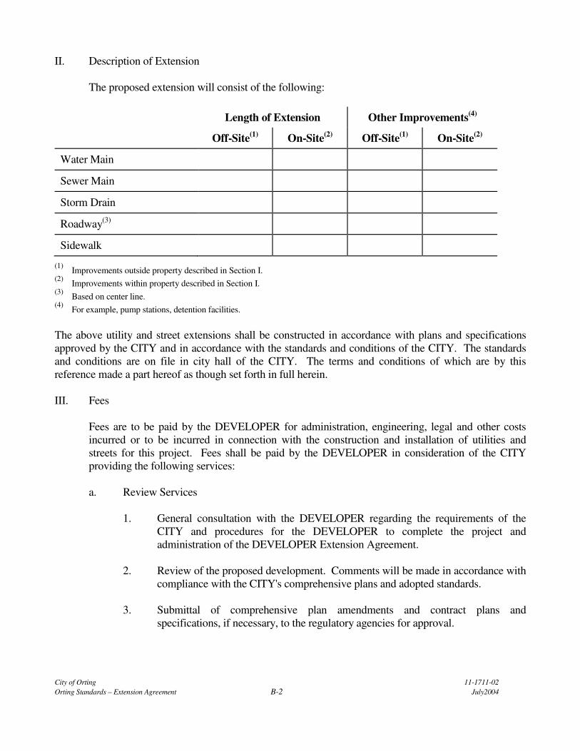
City of Orting 11-1711-02
Orting Standards – Extension Agreement B-2 July2004
II. Description of Extension
The proposed extension will consist of the following:
Length of Extension Other Improvements(4)
Off-Site(1)
On-Site(2)
Off-Site(1)
On-Site(2)
Water Main
Sewer Main
Storm Drain
Roadway(3)
Sidewalk
(1) Improvements outside property described in Section I.
(2) Improvements within property described in Section I.
(3) Based on center line.
(4) For example, pump stations, detention facilities.
The above utility and street extensions shall be constructed in accordance with plans and specifications
approved by the CITY and in accordance with the standards and conditions of the CITY. The standards
and conditions are on file in city hall of the CITY. The terms and conditions of which are by this
reference made a part hereof as though set forth in full herein.
III. Fees
Fees are to be paid by the DEVELOPER for administration, engineering, legal and other costs
incurred or to be incurred in connection with the construction and installation of utilities and
streets for this project. Fees shall be paid by the DEVELOPER in consideration of the CITY
providing the following services:
a. Review Services
1. General consultation with the DEVELOPER regarding the requirements of the
CITY and procedures for the DEVELOPER to complete the project and
administration of the DEVELOPER Extension Agreement.
2. Review of the proposed development. Comments will be made in accordance with
compliance with the CITY's comprehensive plans and adopted standards.
3. Submittal of comprehensive plan amendments and contract plans and
specifications, if necessary, to the regulatory agencies for approval.
City of Orting 11-1711-02
Orting Standards – Extension Agreement B-3 July2004
b. Construction Engineering Services
1. Inspection of the construction in progress as required to assure that the construction
of the utilities and roadway system is in accordance with the construction plans and
specifications and CITY standards.
2. Inspection of pressure tests of pipelines and other tests required for utilities is
outlined in the CITY standards. Inspection of any retesting which may be
necessary and sampling for the purposes of water quality control.
3. Final inspection of the completed project. Preparation of inspection reports and
setting forth any deficiencies that may exist.
4. Re-inspection of any deficient work.
5. Review of as-built plans provided by the DEVELOPER which are to conform to
construction records.
c. Legal Services
1. Review DEVELOPER's Extension Agreement, easements, insurance, and bonds.
2. Prepare the resolutions for amending comprehensive plans as necessary, accepted
DEVELOPER Extension Agreements and other agreements as necessary.
3. Prepare latecomers agreement if required.
d. Additional Services
1. Additional engineering review that may be necessary for changes in contract plans
and/or specifications and/or changes in conditions.
2. In the event this agreement is referred or placed into the hands of attorneys by the
CITY for review and/or enforcement of any portion or if suit is instituted with
respect to this agreement, then in either event the DEVELOPER and additional
Owner shall pay reasonable attorney's fees as may be incurred by the CITY or
ordered by the court, court costs and all other expenses in connection therewith as
may be incurred by the CITY.
e. Other Costs - Such fees and additional charges as required by governmental agencies
charges in lieu of assessments, general facility charges, publication costs, notification
costs, and other such additional costs and charges as incurred by the CITY in connection
with the execution of this DEVELOPER Extension Agreement or as are established by
ordinance and/or resolution of the CITY.
City of Orting 11-1711-02
Orting Standards – Extension Agreement B-4 July2004
IV. Extension Fees
a. Review Engineering Services.
A deposit for engineering review services shall be $50.00 per lot. This shall be paid prior
to submitting construction plans for review by the CITY. The DEVELOPER will be
responsible for any additional costs connected with review of corrected plans and
specifications that are resubmitted.
b. Construction Engineering Services.
The fee for construction engineering services shall be on an actual time and expense basis. A
deposit shall be made in the amount of $1.20 per lineal foot of water main, plus $1.20 of lineal
foot of sewer main, plus $1.20 per lineal foot of storm drain. The total of these costs shall be
deposited with the CITY prior to construction approval. The minimum deposit shall be $1,800.00
if the total length of utilities is less than 1,500 lineal feet.
c. Legal Services.
The deposit for legal services shall be 15 cents per lineal foot of water main, plus 15 cents per
lineal foot of sewer main, plus 15 cents per lineal foot of storm drain with a minimum deposit of
$225.00 if the collective extension is less than 1,500 lineal feet. The fees charged for legal
services shall be on an actual time and expense basis.
d. Additional Services.
Additional services shall be provided on an actual time and expense basis. DEVELOPERs shall
pay final charges and fees prior to acceptance of the improvements by the CITY.
e. Other Costs.
Fees and charges for all other costs described in Section IIIe shall be based on actual invoice
amounts or in such amount as established by CITY resolution and/or ordinance for each such fee
and/or charge.

City of Orting 11-1711-02
Orting Standards – Extension Agreement B-5 July2004
V. Calculation of Deposits
Review Engineering:
Number of Lots _______ x $50 = $___________
Deposit shall be made prior to submitting design plans for review.
Construction Engineering and Legal Services:
Total length of Utilities (excluding sidewalks) from
Section III __________ x $1.35 = $_______________
Deposit shall not be less than $2,525.00 for a subdivision, and $500.00 for a short subdivision.
Deposit shall be made prior to construction.
VI. Latecomers Agreements
If DEVELOPER desires to enter into a Latecomers Agreement providing for reimbursement
and/or contribution from property owners that benefit from the extension of certain utilities, said
agreement shall be made a part of this document herein and shall be attached. All Latecomers
Agreements are subject to the sole approval of the CITY.
VII. Evidence of Insurance
The DEVELOPER shall provide to the CITY written evidence of insurance covering public
liability and property damage to third parties in which the CITY and it's Engineer shall be named
as an insured.
VIII. Cash Deposit
DEVELOPER agrees to have any contractor installing an extension in accordance with this
application and agreement provide for the CITY a cash deposit of $1,000.00 prior to beginning
construction of said extension, and no construction shall be commenced until said cash deposit is
furnished. This cash deposit shall be conditioned upon the contractor's strict compliance with the
CITY's conditions and standards contained herein and shall insure the CITY against any damage
to the existing system as a result of the contractor's failure to comply. Deposit shall not apply to
Subcontractors.
The cash deposit will be refunded to the contractor upon satisfactory completion of the extension
and connection of the extension to the existing system. In the event of the contractor's failure to
comply, the CITY may exercise the right to irrevocably forfeit the total amount of the cash deposit
as liquidated damages.

City of Orting 11-1711-02
Orting Standards – Extension Agreement B-6 July2004
IX. Easements
Any required easements shall be obtained by the DEVELOPER at his sole cost and expense, and
shall name the CITY as grantee, and a true and fully executed copy of such easement in a form
acceptable to the CITY shall be delivered to the CITY prior to the time DEVELOPER commences
construction hereunder. Upon completion of construction and prior to acceptance of said
extension by CITY in accordance with the provisions hereof, the original easement shall be
delivered to the CITY. The DEVELOPER shall provide all necessary easements at his sole cost
regardless of changes in the Contract Plans, together with good and sufficient evidence of title and,
if required, a title insurance policy in sum not less than $1,000 per 500 feet of easement,
establishing clear title to the easement in the CITY.
X. Permits
All the necessary permits from any governmental agency shall be obtained by the DEVELOPER
directly or, only if required, CITY will obtain the same, but at DEVELOPER's expense; and CITY
shall be provided with a copy of all such permits before construction commences.
XI. Contractors, Subcontractors, Labormen, and Materialmen
The CITY has a substantial interest in determining that the extension is to be constructed and
connected to the existing system of the CITY in a good workmanlike manner and, therefore, the
DEVELOPER and/or additional owners agree to submit the names of all contractors,
subcontractors, materialmen, and suppliers, or in the event that the owner or additional owners are
contractors, then a statement that said DEVELOPER or additional owner will perform said
improvement, and the CITY reserves the right to approve or disapprove of the same, which
approval the CITY will not unreasonably withhold; however, in determining whether said
DEVELOPER, additional owner, contractor, subcontractor, materialmen, or laborer is or is not
satisfactory, the CITY can take into consideration said parties' financial ability, prior work
performed by said party for or on behalf of the CITY, and the recommendation of the CITY
Engineer. Said names shall be submitted prior to any construction being performed with respect to
said real property described in this agreement and, if said party is not acceptable to the CITY, the
CITY will so notify the DEVELOPER within 15 days after notification is given to the CITY of the
name of said party, whereupon the DEVELOPER and/or additional owner shall re-submit
alternates and said alternates shall likewise be subject to the same approval, upon the same criteria
as the original party submitted, and notification will be given by the CITY within the same period
of time specified.
XII. Performance Bond
DEVELOPER shall furnish to CITY a performance bond between DEVELOPER and the CITY
upon the form approved by CITY and in an amount equal to 125% of the Engineer's estimated
cost of the project, or actual cost, if known, whichever is less, prior to the staking of the extension
for construction.
City of Orting 11-1711-02
Orting Standards – Extension Agreement B-7 July2004
The performance bond shall assure and guarantee the payment of all persons furnishing labor and
materials and completion of the improvements including payment of all fees required herein in
accordance with the terms hereof, and shall hold the CITY harmless from any claims thereof,
whether any such claim would arrive under the public works lien statutes or the mechanic lien
statutes of the State of Washington, and compliance with the formal requirements of either or both
of said statutes shall not be a condition of recovery upon said bond.
XIII. Grading of Roads
DEVELOPER shall grade all roads to the design subgrade elevation prior to the start of
construction and shall advise the CITY in writing of any changes which may be contemplated
during construction. If the DEVELOPER changes the subgrade elevation of the road after
completion of the extension or any part thereof, the DEVELOPER shall be responsible for all
costs incurred to raise or lower the pipelines or other improvements as required as a result of said
change in subgrade elevation. This obligation shall remain in full force until CITY releases the
bond in connection with the DEVELOPER's obligation to the CITY for construction of the roads
and streets.
XIV. Connection to the CITY's Utility System
Not less than 48 hours prior to the time that said extension is partially or fully completed and
connection to the CITY's system is desired, written application for permission to make the actual
connection to the CITY's system at a specified time shall be made by DEVELOPER or his
contractor. All connections to the existing system and all testings of the new line shall require
authorization of the CITY and its Engineer and shall be conducted in the presence of the CITY's
Engineer and/or his authorized representatives. For pressurized pipelines the CITY reserves the
right to require that connections be made by live tap where disruption of service would, in the
opinion of the CITY, be detrimental.
XV. Condition Precedent
Compliance with the terms and conditions of the DEVELOPER Extension Agreement and all
applicable resolutions of the CITY shall be a condition precedent to the CITY's obligation to
accept a Bill of Sale and a condition precedent to the CITY's agreement to maintain and operate
the improvements and to provide service to the real property that is the subject matter of this
agreement, and particularly, without limiting the generality of the aforesaid, the CITY shall be
under no obligation to allow connections to the utility system of any portion of the real property
described in this application if there are any fees or costs due and owing to the CITY arising from
this agreement and resolutions of the CITY or from regulations, resolutions, or ordinances of any
other governmental agency.
The CITY shall not be obligated to provide utility service to the property herein described if
construction by third parties of facilities to be deeded to the CITY has not been completed and title
accepted by the CITY if said third party facilities are necessary to provide utility service to the real
property to be served.
City of Orting 11-1711-02
Orting Standards – Extension Agreement B-8 July2004
XVI. Acceptance for Use and Operation
At such times as the extension is partially completed or it is not ready for acceptance of title by
CITY by reason of other incomplete plat improvements, and one or more residences therein are in need of utility service and the CITY is satisfied that the extension will be completed, the CITY may, but is not required to, accept the system in a platted subdivision for use and operation only and authorize temporary utility service to the designated residences. In order to insure that the DEVELOPER will complete the system in the entire subdivision or specific phase thereof for which this application is filed, the CITY reserves the right to designate the number of residences or other structures which can be connected to the system for temporary service upon acceptance of a partially completed system for use and operation by the CITY and also reserves the right to refuse to connect all residences or other structures to the utility system as installed until the CITY can be assured that the system will be completed in accordance with this application.
Acceptance for use and operation shall be subject to satisfactory completion of the following: a. Passing tests on all required parts in the system; and b. Acceptance by the appropriate agencies of the State of Washington Department of Health;
Department of Ecology; Department of Labor and Industries; or any other governmental agency having jurisdiction.
c. Inspection and approval by CITY Engineer of the system for use and operation in
accordance with the plans and specifications. After satisfactory completion of the test and inspection provided for in Section IIIb and acceptance
of the utilities for use and operation only, the CITY may connect such extensions to the utility system and furnish temporary service to such residences as it may designate, which residences shall be subject to the charges and subject to all resolutions, rules, regulations, and policies of the CITY.
The charges for the use and operation inspection shall be paid for under fees outlined in Section IV
of this Agreement, and shall be based on the actual time and expense incurred by CITY or their authorized representative and paid for as “additional inspection.” Any subsequent re-inspection of the deficient work which may have prevented final inspection of the improvements shall also be based on actual time and expense incurred.
XVII. Final Acceptance The CITY agrees to accept title to the utility and street systems at such time as all work has been
completed, and any damage, which may have been caused thereby, has been repaired, and the CITY's Engineer has made final inspection and given approval of the system as having been completed in accordance with the plans and specifications. DEVELOPER shall execute and deliver to the CITY a Bill of Sale in the form approved or furnished by the CITY containing a two-year warranty. Upon acceptance of title by the CITY, said extension shall be subject to the control, use and operation of the CITY and all regulations applicable to service and charges therefore as established by the CITY from time to time.
City of Orting 11-1711-02
Orting Standards – Extension Agreement B-9 July2004
Such acceptance by CITY shall not relieve the DEVELOPER of the obligations to correct defects in labor and/or materials as heretofore provided and/or the obligation set forth in applicable paragraphs hereof nor for liability to third parties arising from the DEVELOPER's completed system. After acceptance of the extension by CITY and the transferring of title to such extension as set forth above, the DEVELOPER shall furnish a Maintenance Bond which shall continue in force from the date of acceptance and transfer of title by CITY in lieu of the Performance Bond required herein. The bond shall be in a form acceptable to CITY and shall require the DEVELOPER and/or bonding company to correct defects in labor and material which arise in said system for a period of two (2) years from the date of acceptance and transfer of title. The maintenance bond shall be in an amount equal to fifteen percent (15%) of cost of said extension, or a minimum of Ten Thousand Dollars ($10,000).
XVIII. Limitation of Period for Acceptance The extension shall be complete and accepted within one year of date of acceptance of this
application by CITY. The completion and acceptance of the extension within the one-year period shall be subject to the following provisions.
a. Failure to Commence Construction In the event the DEVELOPER, after the receipt of approved construction plans, has not
commenced construction and posted the required performance bond, and, if CITY determines, in its absolute discretion, that it is necessary that the DEVELOPER extension be completed in order that the CITY can provide utility service to other property and completion of the extension is necessary to provide utility service to other property, then in such event, the CITY may give the DEVELOPER or additional owners notice that construction of the system improvements must be commenced within sixty (60) calendar days of the notice by the CITY to said DEVELOPER and/or additional owners, provided that plans have been prepared by the CITY and submitted to said DEVELOPER and/or additional owners and, if construction is not commenced within the time specified, then the CITY may, at its discretion, determine that this Agreement is terminated and the CITY shall retain all payments made by the DEVELOPER to the CITY and the CITY shall be free to proceed with construction of the improvements in the manner and method provided by law. If delay in plans is occasioned by failure of the DEVELOPER to provide necessary data to the CITY Engineer for a period of thirty (30) days after notice, then this Agreement likewise can be terminated and the CITY may proceed with construction of the improvements in the manner and methods provided by law.
b. Failure to Complete Construction If the extension is not completed and accepted within one year from the date below, then
the DEVELOPER's rights under this agreement shall cease and no additional utility services (if any utility services have been connected to the extension under the provisions of acceptance for temporary use and operation) shall be connected to such extension unless and until DEVELOPER shall make a new Application and the DEVELOPER shall pay the additional administrative, legal, engineering, and inspection costs involved, all as determined by the CITY.

City of Orting 11-1711-02
Orting Standards – Extension Agreement B-10 July2004
In the event no new application or renewal of the existing application is made, the CITY
may proceed to require completion of construction under the provisions of the
DEVELOPER's Performance Bond, if determined in the sole discretion of the CITY to be
necessary for CITY purposes.
XIX. Warranty of Authority
The undersigned DEVELOPER and additional owners warrant that they constitute the owners of
all of the real property that is the subject matter of this Agreement and upon the request of the
CITY agree to provide title insurance or preliminary title report, at the CITY's option and at the
DEVELOPER's sole cost and expense, establishing to the satisfaction of the CITY that the parties
executing this application constitute the owners of all the real property described and have the
authority to execute this Agreement with respect to said real property.
DATED at , Washington, this day of , 20
DEVELOPER's ADDRESS
Additional Owners
Upon compliance with the terms and conditions of the application and Contract Documents furnished by
the CITY to the above-named DEVELOPER, the City of Orting will accept said extension and furnish
utility service thereto.
CITY OF ORTING
Pierce County, Washington
By
Mayor

APPENDIX C
BILL OF SALE
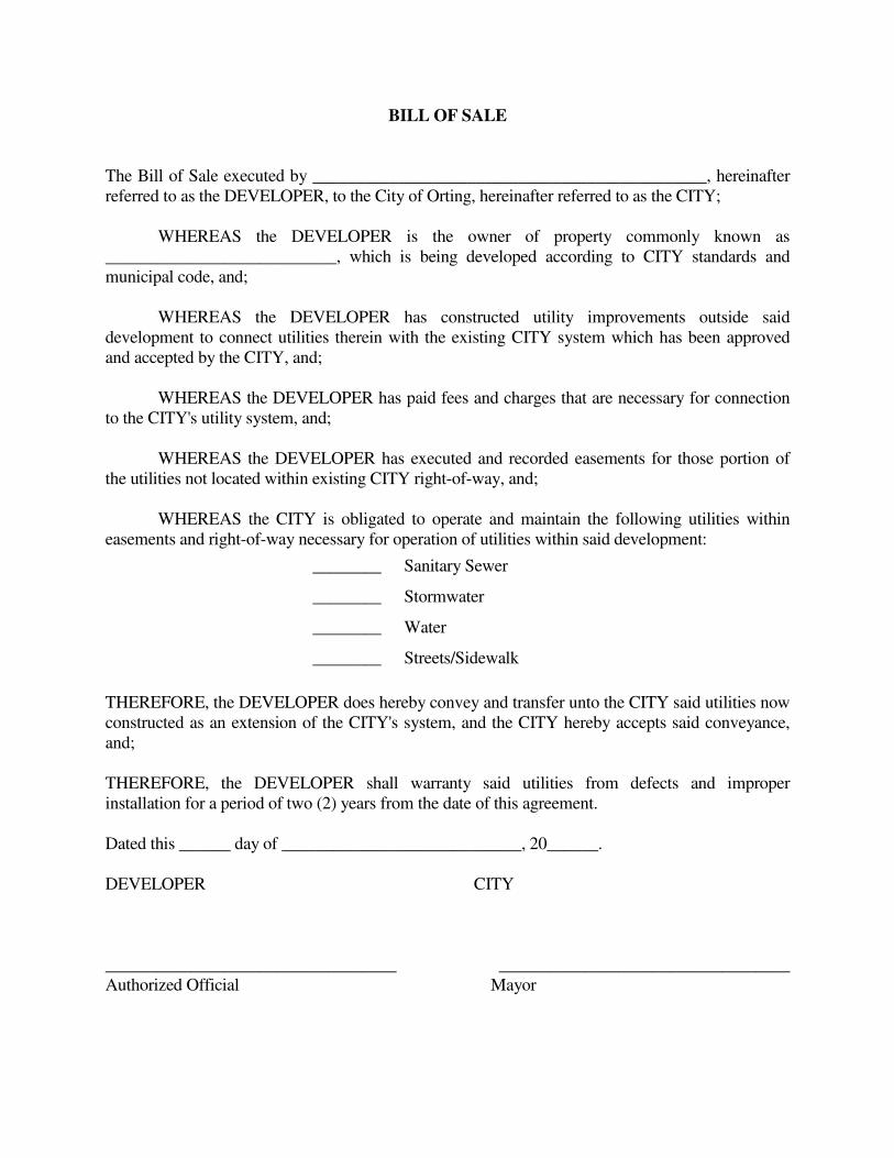
BILL OF SALE
The Bill of Sale executed by ______________________________________________, hereinafter
referred to as the DEVELOPER, to the City of Orting, hereinafter referred to as the CITY;
WHEREAS the DEVELOPER is the owner of property commonly known as
___________________________, which is being developed according to CITY standards and
municipal code, and;
WHEREAS the DEVELOPER has constructed utility improvements outside said
development to connect utilities therein with the existing CITY system which has been approved
and accepted by the CITY, and;
WHEREAS the DEVELOPER has paid fees and charges that are necessary for connection
to the CITY's utility system, and;
WHEREAS the DEVELOPER has executed and recorded easements for those portion of
the utilities not located within existing CITY right-of-way, and;
WHEREAS the CITY is obligated to operate and maintain the following utilities within
easements and right-of-way necessary for operation of utilities within said development:
________ Sanitary Sewer
________ Stormwater
________ Water
________ Streets/Sidewalk
THEREFORE, the DEVELOPER does hereby convey and transfer unto the CITY said utilities now
constructed as an extension of the CITY's system, and the CITY hereby accepts said conveyance,
and;
THEREFORE, the DEVELOPER shall warranty said utilities from defects and improper
installation for a period of two (2) years from the date of this agreement.
Dated this ______ day of ____________________________, 20______.
DEVELOPER CITY
__________________________________ __________________________________
Authorized Official Mayor

APPENDIX D
PLAN REQUIREMENTS
City of Orting 216-1711-003 (7037)
Orting Standards – Plan Requirements D-1 April 1999
PLAN REQUIREMENTS
The plans for street design shall conform to the requirements of Sections 3 and 4. The following
requirements shall also be shown on the plans where applicable.
Road and Storm Plans:
• Plan and profile view.
• All existing trees 6 inches in diameter or larger, and which trees are proposed
to be removed and remain.
• Existing and proposed contours at 1-foot intervals.
• The fill and/or excavation quantities in cubic yards.
• The type of fill materials and compaction requirements.
• State whether or not the fill material will be placed upon native or
stripped vegetation.
• Cross-sections at 200 feet minimum intervals showing the fill/grading shall be
shown on the plans through all properties, and 30 feet beyond the property
lines.
• Limits of grading.
• Street names.
• Center line bearings.
• Center line/baseline stationing.
• Center line elevations at 50-foot intervals, except as otherwise stated.
• Where transverse slope (crown) varies from 3 percent, include gutter line
elevations at 50-foot intervals, and the beginning, end, and other critical
locations throughout the duration of slope variations (i.e., P.C.'s, P.T.'s,
B.V.C.'s, E.V.C.'s and slope transition changes).
• Center line grade shall be in percentage.
City of Orting 216-1711-003 (7037)
Orting Standards – Plan Requirements D-2 April 1999
• Horizontal curve datum at center line.
• Vertical curve datum at center line.
• Intersection gutter line elevations at 1/4 points and right-of-way curve.
• Intersection elevation datum at 1/4 points of radii.
• Accurate locations of monuments at all center line intersections, cul-de-
sacs, P.C.'s, P.T.'s and P.R.C.'s.
• Location, length, width of sidewalks, and driveways.
• Length, type, and location of curb and gutter.
• Wheelchair ramp locations.
• Right-of-way and width; lot/subdivision lines and street addresses.
• Right-of-way radii.
• Curb to curb pavement width.
• Mailbox design and/or placement/replacement.
• Street landscaping.
• Standard street construction notes.
• Legend (complete for existing and new).
• Storm drainage system.
• Utility locations (new and existing) for:
� Water system
� Sanitary sewer system
� Gas
� Telephone
� Power
� Cable TV
� Address any horizontal or vertical conflicts

City of Orting 216-1711-003 (7037)
Orting Standards – Plan Requirements D-3 April 1999
Street Light Plans:
• Street light layout plans shall be on separate drawings from the street
plan/profile sheets. The final locations shall be determined by the City
Engineer after the City receives a copy of the Puget Power transformer layout
design drawings. Street light bases shall be located 22 inches from face of
curb to center of light standard bolt circle.
• Street light disconnects shall be located near the power transformers.
• Street light conduit for wiring shall be located within the utility easement
for power, gas, telephone, and cable TV wherever possible.
• Street Light: Location, type, height, and wattage.
• Service Cabinets: Location and type.
• Conduits and Wire: Location, type, size, and length.
• Junction Boxes: Locations and types.
Channelization and Signing Plans:
• Incorporated with “Street Light Plans”.
• Lane Markers: Locations and types.
• Pavement Markings: Locations and types.
• Signs: Locations, types, and mountings.
• Painted street curbs.
Signalization Plans:
• Separate detailed plans required.
• Pole base locations.
• Traffic loop location.
• Conduit location.
City of Orting 216-1711-003 (7037)
Orting Standards – Plan Requirements D-4 April 1999
• Details of traffic signal system to be reviewed and approved by the City
Engineer.
• Location of power source.
Storm Drainage Plan Requirements:
The following requirements shall be shown on the street plans:
• Plan and profile.
• Storm pipe including locations, lengths, materials, slopes, depths, and
sizes.
• Manholes and catch basins including location, types, and rim and invert
elevations. All new and existing manholes and catch basins shall be
numbered consecutively.
• Typical ditch cross-sections shall be shown on the plans.
• Easement widths and locations.
• Identify any possible utility conflicts.
• Roof drain connections.
• The distance from the center line of pipes to any building structure.
• An all-weather maintenance access to all structures, ditches, ponds, etc.,
including typical cross-section of said access road.
WATER SYSTEM DESIGN REQUIREMENTS
Water Mains:
• All new water main lines shall be installed to the size as indicated in the City's
Comprehensive Plan. The minimum water main pipe size shall be
8 inches in diameter.

City of Orting 216-1711-003 (7037)
Orting Standards – Plan Requirements D-5 April 1999
• Connections to existing water mains shall be wet taps through a tapping tee
and tapping valve and shall be made by a city approved contractor. The City
shall approve the time and location for these connections.
• Where water mains are to be extended to serve a particular property, the water
lines shall be extended along the entire frontage of the property to be served.
Looped connections may be required to maintain continuity in the system.
• All public water mains shall have a minimum cover of 36 inches in improved
right-of-way, and 42 inches cover in unimproved right-of-way or easements.
• All water mains and appurtenances shall be hydrostatically tested at 200 psi in
accordance with Section 7-11.3(11) of the Standard Specifications.
• Two-inch (2″) Blow-off Assemblies are required on dead-end water lines,
except where fire hydrants are installed at the dead-end. The blow-off
assembly shall be installed in accordance with City Standards. Water
valves shall be installed along the water line at a maximum space of 400
feet and at the intersection of lateral lines.
• Minimum distance between sewer and water lines shall be 10 feet horizontally
and 1-foot vertically.
• Air relief valves are required at high points in water lines. Air relief
valves shall be installed in accordance with City Standards.
• Water valves shall be located in clusters when possible and shall be
located so that each leg of the main line system can be isolated separately.
• Easements shall be a minimum of 20 feet in width for water lines. No
building structures shall be allowed within easements.
• Sampling station per City standards shall be installed by the developer at
locations designated by the City.
Fire Hydrants:
• Fire hydrants shall be installed at a maximum lateral spacing of 600 feet along
streets in single-family residential zones. A fire hydrant is required within
300 feet of a proposed structure on a new building lot.
City of Orting 216-1711-003 (7037)
Orting Standards – Plan Requirements D-6 April 1999
Fire Service Connections:
• A double detector check valve assembly (DDCVA) complete with 3/4-inch
bypass DCVA and 5/8-inch Rockwell SR-II water meter reading in cubic feet
is required on the fire service line to any building which is equipped with a
fire sprinkler system.
• The DDCVA shall be located in a vault at or near the property line and
shall be installed in accordance with City Standard.
• Upon approval of the installation by the City Inspector, the DDCVA and
the DCVA shall be tested with a Washington State certified backflow
assembly tester, and the test report results shall be submitted to the City prior
to use of the water system.
• The domestic water service shall not be connected directly to a fire system
service line, but rather shall be a separate connection to the main line.
• The fire department connection shall be located within 15 feet of a fire
hydrant but not less than 10 feet.
• All underground piping shall be installed by a State of Washington
Licensed Sprinkler Contractor.
Brass or dielectric unions shall be installed immediately downstream of all backflow
assemblies 2 inches and smaller. A Rockwell #912 (or approved equal) flanged coupling
adapter shall be installed on the immediate upstream side of all backflow assemblies 3 inches
and larger.
All landscape irrigation systems require backflow protection. The City will determine
the type of backflow device required for each installation.
Integral air-vacuum breakers are required on all threaded water outlets, including lab
faucets, janitor sink faucets, and hose bib faucets.
Water System Plan Requirements:
The following items shall be shown on the plans:
• Plan and profile.
• Water pipe, including location, length, material, slope, depth, and size.
City of Orting 216-1711-003 (7037)
Orting Standards – Plan Requirements D-7 April 1999
• Detail all new connections to the existing water system.
• Identify any possible utility conflicts.
• Stationing and reference points.
• Valves, meters, and fittings, including size and location.
• Fire hydrant protection if hydrant is not protected by street curb and
gutter.
• Blow-offs at low points or dead-ends (2-inch minimum).
• Air and vacuum relief valve at high points.
• Pressure reducing valves.
• Concrete blocking.
• An all-weather maintenance access, including typical cross-section of said
access road.
• Service sizes and locations.
• Meter sizes and locations.
• Minimum one (1) service per lot.
• Sewer deduct meter locations and sizes.
SANITARY SEWER PLAN REQUIREMENTS
The following requirements shall be shown on the plans:
• Plan and profile.
• Sanitary sewer pipe, including locations, length, material, slope, depth,
and size.
• Manholes, including location, type, and rim and invert elevations. All
new manholes shall be numbered consecutively.
City of Orting 216-1711-003 (7037)
Orting Standards – Plan Requirements D-8 April 1999
• Detail any inside drop manhole connections per City Standard.
• Identify any possible utility conflicts.
• Provide stationing and reference points.
• All public sewer main lines shall be located within roadway rights-of-way
or easements.
• Location and stationing from downstream manholes shown.
• Perpendicular connection of side sewers to the main lines.
• Proper reference and layout for saw cutting and patching existing streets.
• An all-weather maintenance access, including typical cross-section of said
access roads.

APPENDIX E
AS-BUILT REQUIREMENTS

City of Orting 216-1711-003 (7037)
Orting Standards – As-built Requirements E-1 April 1999
AS-BUILT REQUIREMENTS
• Submit a complete set of mylar copies of design Drawings with verification of all utility
location, both horizontal and vertical, by a professional land surveyor and sealed with a
stamp.
• All elevations and slopes shall be verified with a check, or the corrected numbers written
in with the design number lined out.
• Each sheet shall be stamped “Record Drawing” or “As-built Drawing” and dated.
• All changes to the original Drawings shall be shown on the mylars.
• Submit four sets of blueline copies with the mylars.
• Obtain City approval of the As-built Drawings prior to submittal of the mylars.
• Submit all drawings in AutoCAD to City.

APPENDIX F
EROSION CONTROL PRACTICES FOR
SINGLE FAMILY RESIDENCES AND SMALL SITES
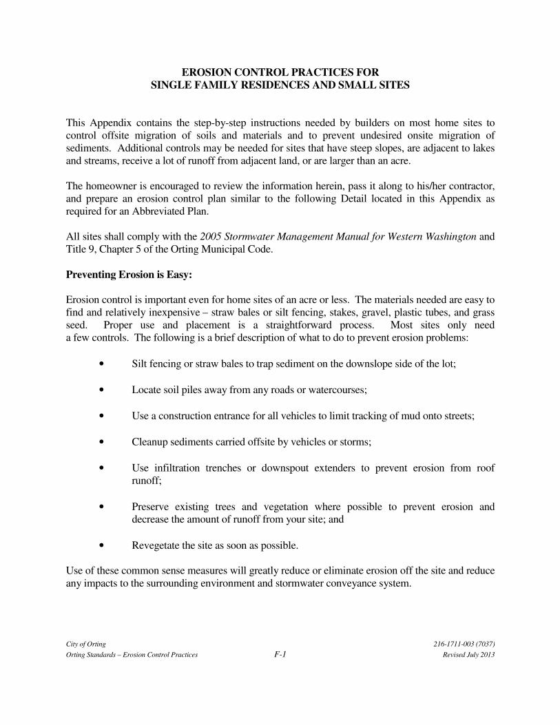
City of Orting 216-1711-003 (7037)
Orting Standards – Erosion Control Practices F-1 Revised July 2013
EROSION CONTROL PRACTICES FOR
SINGLE FAMILY RESIDENCES AND SMALL SITES
This Appendix contains the step-by-step instructions needed by builders on most home sites to
control offsite migration of soils and materials and to prevent undesired onsite migration of
sediments. Additional controls may be needed for sites that have steep slopes, are adjacent to lakes
and streams, receive a lot of runoff from adjacent land, or are larger than an acre.
The homeowner is encouraged to review the information herein, pass it along to his/her contractor,
and prepare an erosion control plan similar to the following Detail located in this Appendix as
required for an Abbreviated Plan.
All sites shall comply with the 2005 Stormwater Management Manual for Western Washington and
Title 9, Chapter 5 of the Orting Municipal Code.
Preventing Erosion is Easy:
Erosion control is important even for home sites of an acre or less. The materials needed are easy to
find and relatively inexpensive – straw bales or silt fencing, stakes, gravel, plastic tubes, and grass
seed. Proper use and placement is a straightforward process. Most sites only need
a few controls. The following is a brief description of what to do to prevent erosion problems:
• Silt fencing or straw bales to trap sediment on the downslope side of the lot;
• Locate soil piles away from any roads or watercourses;
• Use a construction entrance for all vehicles to limit tracking of mud onto streets;
• Cleanup sediments carried offsite by vehicles or storms;
• Use infiltration trenches or downspout extenders to prevent erosion from roof
runoff;
• Preserve existing trees and vegetation where possible to prevent erosion and
decrease the amount of runoff from your site; and
• Revegetate the site as soon as possible.
Use of these common sense measures will greatly reduce or eliminate erosion off the site and reduce
any impacts to the surrounding environment and stormwater conveyance system.

City of Orting 216-1711-003 (7037)
Orting Standards – Erosion Control Practices F-2 Revised July 2013
STEP-BY-STEP
EROSION CONTROL PRACTICES
Following these steps will reduce erosion on- and off-site.
Filter Fabric Fencing or Straw Bales:
• Install prior to any other work being done.
• Install on downslope side(s) of site with ends extended up side slopes a short
distance.
• Place parallel to the contour of the land to allow water to pond behind the fence.
• Entrench into the ground.
• Stake (1 stake every 3 feet for filter fabric fencing or 2 stakes per bale).
• Leave no gaps between bales or sections of filter fabric fencing.
• Inspect and repair once a week and after every large rainfall. Remove sediment
if deposits reach more than 6 inches.
• Maintain until a lawn or permanent landscaping is in place.
Soil Piles:
• Locate away from any downslope street, stream, lake, wetland, ditch, or
drainageway.
• Temporary seed such as annual rye is recommended for topsoil piles which will not
be moved through the winter.
Construction Entrances:
• Install a construction entrance.
• Use to prevent tracking of dirt onto the road by all vehicles.
• Maintain throughout construction.
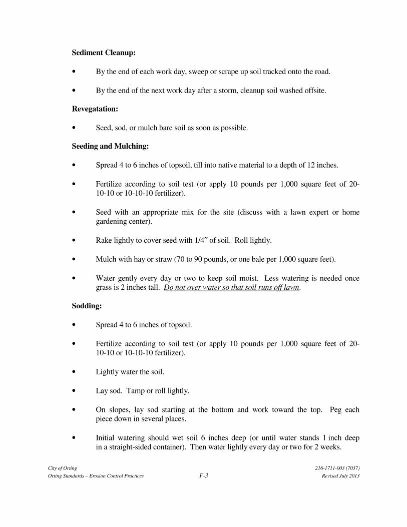
City of Orting 216-1711-003 (7037)
Orting Standards – Erosion Control Practices F-3 Revised July 2013
Sediment Cleanup:
• By the end of each work day, sweep or scrape up soil tracked onto the road.
• By the end of the next work day after a storm, cleanup soil washed offsite.
Revegatation:
• Seed, sod, or mulch bare soil as soon as possible.
Seeding and Mulching:
• Spread 4 to 6 inches of topsoil, till into native material to a depth of 12 inches.
• Fertilize according to soil test (or apply 10 pounds per 1,000 square feet of 20-
10-10 or 10-10-10 fertilizer).
• Seed with an appropriate mix for the site (discuss with a lawn expert or home
gardening center).
• Rake lightly to cover seed with 1/4″ of soil. Roll lightly.
• Mulch with hay or straw (70 to 90 pounds, or one bale per 1,000 square feet).
• Water gently every day or two to keep soil moist. Less watering is needed once
grass is 2 inches tall. Do not over water so that soil runs off lawn.
Sodding:
• Spread 4 to 6 inches of topsoil.
• Fertilize according to soil test (or apply 10 pounds per 1,000 square feet of 20-
10-10 or 10-10-10 fertilizer).
• Lightly water the soil.
• Lay sod. Tamp or roll lightly.
• On slopes, lay sod starting at the bottom and work toward the top. Peg each
piece down in several places.
• Initial watering should wet soil 6 inches deep (or until water stands 1 inch deep
in a straight-sided container). Then water lightly every day or two for 2 weeks.
City of Orting 216-1711-003 (7037)
Orting Standards – Erosion Control Practices F-4 Revised July 2013
Preserving Existing Vegetation:
• Whenever possible, preserve existing trees, shrubs, and other vegetation.
• To prevent root damage, do not grade, place soil piles, or park vehicles near
trees marked for preservation.
• Place plastic mesh or snow fence barriers around trees to protect the area below their
branches.
Reference: Washington State Department of Ecology. 2005. Stormwater Management Manual
for Western Washington. February 2005. Publication Numbers 05-10-029 through
05-10-033.