CITY OF MILPITAS NON-RESIDENTIAL 455 E. Calaveras Blvd. RE ... · CH Re-roof Commercial Page 3 of 7...
19
CH Re-roof Commercial Page 1 of 7 1/01/11 CITY OF MILPITAS Building & Safety Department 455 E. Calaveras Blvd. Milpitas, CA 95035 408-586-3240 www.ci.milpitas.ca.gov NON-RESIDENTIAL RE-ROOF 1. PERMIT INFORMATION: The replacement or repair of more than One Square (100 SQ. FT.) of roofing material requires a building permit. Other than on “flat roofs”, all changes in roofing materials (including color of material used) must be reviewed and approved by the Planning Department and the permit will have to be obtained in person at the Permit Center. A Building Permit may be issued only to a State of California Licensed Contractor or the Building Owner. If the work is performed by the Building Owner personally or by his/her workers, and an inspection indicates the work cannot be completed satisfactorily, then a licensed contractor must perform the work. If the Building Owner hires workers, State Law requires the Owner to obtain Worker’s Compensation Insurance. Proof of this insurance is required prior to inspection. 2. INSTALLATION REQUIREMENTS : All work must comply with the 2010 California Building Code (CBC), 2010 California Plumbing Code (CPC), 2010 California Mechanical Code (CMC), 2010 California Electrical Code (CEC), 2010 California Energy Code based upon 2008 Building Energy Efficiency Standards (CEnC) and 2011 Milpitas Municipal Code (MMC). Roofing materials must be installed per the manufacturer's installation instructions and CBC Chapter 15. If the roof covering is not removed to the original deck, access to the attic may be required for an under roof check of the structural system, as well as for the condition of the roof deck. At the time of the pre-roofing inspection, all damaged decking and supporting members must be replaced. Class “B” or better roof covering is required for all buildings located in the “Hillside” area (east of North Park Victoria Drive, Evans Road and Piedmont Road) and installed to 95 mph minimum wind speed and exposure C standards (Section II-3-2.09, 2011 Milpitas Municipal Code). Class “C” or better roof covering is required for buildings located in other than “Hillside” areas as per CBC Section 1505.1.3. Structural roof components shall be capable of supporting the roof-covering system and the material and equipment loads that will be encountered during installation of the system. Existing slate, clay or cement tile shall be permitted for reinstallation, except that damaged, cracked or broken slate or tile shall not be reinstalled. Existing vent flashing, metal edgings, drain outlets, collars and metal counterflashings shall not be reinstalled where rusted, damaged or deteriorated. Aggregate surfacing materials shall not be reinstalled. Flashings shall be reconstructed in accordance with approved manufacturer’s installation instructions. Metal flashing, to which bituminous materials are to be adhered, shall be primed prior to installation.
Transcript of CITY OF MILPITAS NON-RESIDENTIAL 455 E. Calaveras Blvd. RE ... · CH Re-roof Commercial Page 3 of 7...

CH Re-roof Commercial Page 1 of 7 1/01/11
CITY OF MILPITAS
Building & Safety Department 455 E. Calaveras Blvd.
Milpitas, CA 95035 408-586-3240
www.ci.milpitas.ca.gov
NON-RESIDENTIAL
RE-ROOF
1. PERMIT INFORMATION:
� The replacement or repair of more than One Square (100 SQ. FT.) of roofing material requires a building permit.
� Other than on “flat roofs”, all changes in roofing materials (including color of material used) must be reviewed and approved by the Planning Department and the permit will have to be obtained in person at the Permit Center.
� A Building Permit may be issued only to a State of California Licensed Contractor or the Building Owner.
� If the work is performed by the Building Owner personally or by his/her workers, and an inspection indicates the
work cannot be completed satisfactorily, then a licensed contractor must perform the work.
� If the Building Owner hires workers, State Law requires the Owner to obtain Worker’s Compensation Insurance. Proof of this insurance is required prior to inspection.
2. INSTALLATION REQUIREMENTS:
� All work must comply with the 2010 California Building Code (CBC), 2010 California Plumbing Code (CPC),
2010 California Mechanical Code (CMC), 2010 California Electrical Code (CEC), 2010 California Energy Code based upon 2008 Building Energy Efficiency Standards (CEnC) and 2011 Milpitas Municipal Code (MMC).
� Roofing materials must be installed per the manufacturer's installation instructions and CBC Chapter 15.
� If the roof covering is not removed to the original deck, access to the attic may be required for an under roof
check of the structural system, as well as for the condition of the roof deck.
� At the time of the pre-roofing inspection, all damaged decking and supporting members must be replaced.
� Class “B” or better roof covering is required for all buildings located in the “Hillside” area (east of North Park Victoria Drive, Evans Road and Piedmont Road) and installed to 95 mph minimum wind speed and exposure C standards (Section II-3-2.09, 2011 Milpitas Municipal Code).
� Class “C” or better roof covering is required for buildings located in other than “Hillside” areas as per CBC
Section 1505.1.3.
� Structural roof components shall be capable of supporting the roof-covering system and the material and equipment loads that will be encountered during installation of the system.
� Existing slate, clay or cement tile shall be permitted for reinstallation, except that damaged, cracked or broken
slate or tile shall not be reinstalled. Existing vent flashing, metal edgings, drain outlets, collars and metal counterflashings shall not be reinstalled where rusted, damaged or deteriorated. Aggregate surfacing materials shall not be reinstalled.
� Flashings shall be reconstructed in accordance with approved manufacturer’s installation instructions. Metal
flashing, to which bituminous materials are to be adhered, shall be primed prior to installation.

CH Re-roof Commercial Page 2 of 7 1/01/11
Milpitas Building & Safety Department Non-Residential Re-roof
� New roof coverings shall not be installed without first removing all existing layers of roof coverings down to the roof deck where any of the following conditions occurs:
• Where the existing roof or roof covering is water soaked or has deteriorated to the point that the existing roof or roof covering is not adequate as a base for additional roofing.
• Where the existing roof covering is wood shake, slate, clay, cement or asbestos-cement tile.
• Where the existing roof has two or more applications of any type of roof covering.
• Exceptions:
1. Complete and separate roofing systems, such as standing-seam metal roof systems, that are designed to transmit the roof loads directly to the building’s structural system and that do not rely on existing roofs and roof coverings for support, shall not require the removal of existing roof coverings.
2. Metal panel, metal shingle and concrete and clay tile roof coverings shall be permitted to be installed over existing wood shake roofs when applied in accordance with the requirements for a combustible concealed space below.
3. The application of a new protective coating over an existing spray polyurethane foam roofing system shall be permitted without tear-off of existing roof coverings.
� Where the application of a new roof covering over wood shingle or shake roofs creates a combustible concealed
space, the entire existing surface shall be covered with gypsum board, mineral fiber, glass fiber or other approved materials securely fastened in place.
� Where the application of a new roof covering creates a combustible concealed space, such as when battens or
metal roofing is installed, fireblocking shall be installed in accordance with CRC R302.11.
� FLAT ROOFS:
• When old roof membrane is removed to original deck, it is recommended (not required) that deck be re-sloped to 1/4 inch per foot minimum.
• In order to prevent excessive accumulation of water (ponding), the roof must be sloped to provide positive roof drainage (CBC Section 1510.1).
• If the roof is not re-sloped to minimum 1/4 inch per foot, the roof membrane installed must be approved for a flat roof installation and roof framing shall be checked for ponding instability as per ASCE7-05, Section 8.4.
3. ENERGY REQUIREMENTS:
� CEnC 149(b)1B: Replacements, recovering or recoating of the exterior surface of existing nonresidential roofs shall meet the requirements of CEnC Section 118(i) (see below). Note: Requirements do not apply to roofs over unconditioned space. For nonresidential buildings, high-rise residential buildings, and hotel/motels, where more than 50 percent of the roof or more than 2,000 square feet of roof, whichever is less, is being replaced, recovered or recoated, this altered roof area shall meet the applicable requirements of the following: 1. Nonresidential buildings with low-sloped roofs (less than or equal to 2:12) shall have a minimum aged solar
reflectance of 0.55 and a minimum thermal emittance of 0.75, or a minimum SRI of 64. Note: This does not apply to high-rise residential buildings and hotels and motels. A. Exceptions (CEnC 143(a)1Ai):
1) Roof area covered by building integrated photovoltaic panels and building integrated solar thermal panels are not required to meet the m minimum requirements for solar reflectance and thermal emittance or SRI.
2) Roof constructions that have thermal mass over the roof membrane with a weight of at least 25 pounds per square foot.

CH Re-roof Commercial Page 3 of 7 1/01/11
Milpitas Building & Safety Department Non-Residential Re-roof
2. Nonresidential buildings with steep-sloped roofs (greater than 2:12) with roofing product density less than 5 pounds per square foot shall have a minimum aged solar reflectance of 0.20 and a minimum thermal emittance of 0.75, or a minimum SRI of 16. Buildings with steep-sloped roofs with product density of 5 pounds per square foot or more shall have a minimum aged solar reflectance of 0.15 and a minimum thermal emittance of 0.75, or a minimum SRI of 10.
3. For nonresidential buildings, high-rise residential buildings and hotels and motels, when low-sloped roofs are exposed to the roof deck or to the recover boards, the exposed area shall be insulated as follows: A. Nonresidential: R-8 continuous insulation with U-factor of 0.081. B. High-rise residential and Hotel/Motel buildings: R-14 continuous insulation with U-factor of 0.055. C. Exceptions:
1) Additional insulation is not required if the roof is already insulated to a minimum level of R-7 or it has a U-factor lower than 0.089.
2) If mechanical equipment is located on the roof and it will not be disconnected and lifted as part of the roof replacement, insulation added may be limited to the maximum insulation thickness that will allow a height of 8 inches from the roof membrane surface to the top of the base flashing.
3) If adding the required insulation will reduce the base flashing height to less than 8 inches at penthouse or parapet walls, the insulation added may be limited to the maximum insulation thickness that will allow a height of 8 inches from the roof membrane surface to the top of the base flashing, provided that the following applies: i. The penthouse or parapet walls are finished with an exterior cladding material other than the
roofing covering membrane material; and ii. The penthouse or parapet walls have exterior cladding material that must be removed to install
the new roof covering membrane to maintain a base flashing height of 8 inches; and iii. For nonresidential buildings, the ratio of the replaced roof area to the linear dimension of affected
penthouse or parapet walls shall be less than 100 square feet per linear foot; and iv. For high-rise residential buildings, hotels or motels, the ratio of the replaced roof area to the
linear dimension of affected penthouse or parapet walls shall be less than 25 square feet per linear foot.
1) Tapered insulation may be used which has a thermal resistance less than that prescribed (R-8 or R-14) at the drains and other low points, provided that the thickness of insulation is increased at the high points of the roof so that the average thermal resistance equals or exceeds the prescribed values (R-8 or R-14).
4. Exceptions: A. Roof coverings allowed by the CBC are not required to meet the above when all of the following occur:
1) The existing roof has a rock or gravel surface; and 2) The new roof has a rock or gravel surface; and 3) There is no removal of existing layers of roof coverings of more than 50 percent of the roof or more
than 2,000 square feet of roof, whichever is less; and 4) There is no recoating with a liquid applied coating; and 5) There is no installation of a recover board, rigid insulation or other rigid, smooth substrate to separate
and protect the new roof recovering from the existing roof. B. If the roofing product does not meet the requirements of Section 149(b)1B above, then the Overall
Envelope TDV Energy Approach of CEnC Section 143(b) may be used and the standard building shall be based on the higher roof/ceiling insulation value of the following (will require submittal of form ENV-3C): 1) For low-sloped roofs, the insulation values specified in CEnC Table 149-A. 2) For steep-sloped roofs, the insulation values specified in CEnC Section 143(a); or 3) The existing installed insulation.

CH Re-roof Commercial Page 4 of 7 1/01/11
Milpitas Building & Safety Department Non-Residential Re-roof
� CEnC 118(i):
1. In order to meet the requirements above, a roofing product’s thermal emittance and 3-year aged solar reflectance shall be certified and labeled by the Cool Roof Rating Council (CRRC), and be listed in the CRRC’s Rated Product directory (see http://www.coolroofs.org). The following is a sample of an approved CRRC product label.
A. Exception: Roofing products that are not certified according to Section 10-113 shall assume the following default aged reflectance/emittance values: 1) For asphalt shingles, 0.08/0.75. 2) For all other roofing products, 0.10/0.75
2. Liquid applied roof coatings applied to low-sloped roofs in the field as the top surface of a roof covering shall: A. Be applied across the entire roof surface to meet the dry mil thickness or coverage recommended by the
coating manufacturer, taking into consideration the substrate on which the coating is applied, and B. Meet the minimum performance requirements listed in CEnC Table 118-B or the minimum performance
requirements of ASTM C836, D3468, D6083, or D6694, whichever are appropriate to the coating material. 1) Exceptions:
i. Aluminum-pigmented asphalt roof coatings shall meet the requirements of ASTM D2824 or ASTM D6848 and be installed as specified by ASTM D3805.
ii. Cement-based roof coatings shall contain a minimum of 20 percent cement and shall meet the requirements of ASTM C1583, ASTM D822, and STM D5870.
� ENERGY FORMS:
• Form ENV-1C must be submitted along with the permit application for ALL re-roof permits.
• Form ENV-3C must be submitted along with the permit application if the roofing product is not CRRC certified.
• Form ENV-INST must be completed and provided to the inspector upon final inspection. 4. SMOKE ALARMS, CARBON MONOXIDE ALARMS & SPARK ARRESTER:
� In single family residences and multi-family (townhomes, condominiums, and apartments), installation of smoke
detectors, carbon dioxide alarms and spark arrestors on all chimneys is required prior to the final inspection as follows:

CH Re-roof Commercial Page 5 of 7 1/01/11
Milpitas Building & Safety Department Re-Roof
• Smoke Alarms: When the value of the work exceeds $1,000, smoke alarms approved and listed by the State Fire Marshal must be installed if they do not already exist in each sleeping room, outside each separate sleeping area in the immediate vicinity of the bedrooms, and on each additional story of the dwelling. In existing buildings, alarms may be solely battery operated where alterations or repairs do not result in the removal of interior walls or ceiling finishes exposing the structure, unless there is an attic, crawl space or basement available which could provide access for building wiring without the removal of interior finishes. Where more than one smoke alarm is required to be installed, the alarms shall be interconnected in such a manner that the activation of one alarm will activate all of the alarms in the individual unit, except where alterations or repairs do not result in the removal of interior wall or ceiling finishes exposing the structure, unless there is an attic, crawl space or basement available which could provide access for interconnection without the removal of interior finishes. The alarm shall be clearly audible in all bedrooms over background noise levels with all intervening doors closed. Refer to CRC Section R314 and the “Smoke Alarms” handout for more additional information.
• Carbon Monoxide Alarms: When the value of the work exceeds $1,000, an approved and listed carbon monoxide alarm shall be installed if they do not already exist in existing dwellings or sleeping units that have attached garages or fuel-burning appliances as follows: outside each separate dwelling unit sleeping area in the immediate vicinity of bedrooms and on every level of dwelling unit. In existing dwelling units a carbon monoxide alarm is permitted to be solely battery operated where repairs or alterations do not result in the removal of wall and ceiling finishes or there is no access by means of attic, basement or crawl space. Where more than one carbon monoxide alarm is required to be installed, the alarms shall be interconnected in a manner that activation of one alarm shall activate all of the alarms in the individual unit, except where repairs do not result in the removal of wall and ceiling finishes, there is no access by means of attic, basement or crawl space, and no previous method for interconnection existed. See CRC Section R315 for additional information.
• Spark arrester: When the value of the work exceeds $1,000, a spark arrester must be installed on fireplace chimneys if one does not already exist per MMC Section II-3-2.06. Spark arresters shall be constructed in conformance with CRC Section 1003.9.1.
� If access to the interior of the dwelling by the Building Inspector cannot be scheduled for inspection of the smoke
detectors and carbon dioxide alarms, Smoke Alarm, Carbon Dioxide Alarm and Spark Arrester Certificate can be filled out by each property owner and provided to the inspector prior to final inspection.
5. INSPECTIONS:
� The City of Milpitas Building inspectors are required to perform the inspections listed below on all re-roof work in the city.
• Pre-Roofing Inspection: After existing roofing is removed but before any new material is installed.
• Roof Nail Inspection: After plywood (or wood) to create solid deck is installed (when applicable).
• In-Progress Inspection: While the roofing material is being installed.
• Smoke detector and spark arrestor inspection: Required to obtain a final.
• Form ENV-INST: Must be completed and provided to the inspector upon final inspection.
• Final Inspection: When all work has been completed, including: o Overflow drains cleaned o Skylights secured o All flues extended and secured o Any roof equipment and/or piping secured o All exposed nails protected o All exposed wood, roof jacks, and metal flashing or edging painted

CH Re-roof Commercial Page 6 of 7 1/01/11
Milpitas Building & Safety Department Re-Roof
� For each inspection, the Permit Card, the Approved Job Copy of the Drawings (if any) and the ICC report on the roofing materials must be presented to the inspector. Permits expire 180 days after issuance or last inspection passed, whichever is the latest.
� The contractor or owner must provide roof access (ladder to roof) for the all required inspections. Ladders must
be OSHA approved, minimum Type I with a 250 lb rating, in good condition and designed for its intended use. 6. QUESTIONS:
� If you have any questions regarding your project, contact the Building & Safety Department at (408) 586-3240.

CH Re-roof Commercial Page 7 of 7 1/01/11
CITY OF MILPITAS
Building & Safety Department 455 E. Calaveras Blvd.
Milpitas, CA 95035 408-586-3240
www.ci.milpitas.ca.gov
SMOKE ALARM, CARBON
MONOXIDE and SPARK
ARRESTER CERTIFICATE
SMOKE ALARMS, CARBON MONOXIDE ALARMS & SPARK ARRESTERS
When building permits are issued for additions, alterations or repairs to residential buildings and the value of the work exceeds $1,000, the installation of smoke alarms, carbon monoxide alarms and a spark arrester on fireplace chimneys, if any, must be installed for safety of the occupants, if they do not already exist.
Smoke alarms approved and listed by the State Fire Marshal must be installed in each sleeping room, outside each separate sleeping area in the immediate vicinity of the bedrooms, and on each additional story of the dwelling. In existing buildings, alarms may be solely battery operated where alterations or repairs do not result in the removal of interior walls or ceiling finishes exposing the structure, unless there is an attic, crawl space or basement available which could provide access for building wiring without the removal of interior finishes. Where more than one smoke alarm is required to be installed, the alarms shall be interconnected in such a manner that the activation of one alarm will activate all of the alarms in the individual unit, except where alterations or repairs do not result in the removal of interior wall or ceiling finishes exposing the structure, unless there is an attic, crawl space or basement available which could provide access for interconnection without the removal of interior finishes. The alarm shall be clearly audible in all bedrooms over background nois levels with all intervening doors closed. Refer to CRC Section R314 and the “Smoke Alarms” handout for more additional information.
An approved and listed carbon monoxide alarm shall be installed in existing dwellings or sleeping units that have attached garages or fuel-burning appliances as follows: outside each separate dwelling unit sleeping area in the immediate vicinity of bedrooms and on every level of dwelling unit. In existing dwelling units a carbon monoxide alarm is permitted to be solely battery operated where repairs or alterations do not result in the removal of wall and ceiling finishes or there is no access by means of attic, basement or crawl space. Where more than one carbon monoxide alarm is required to be installed, the alarms shall be interconnected in a manner that activation of one alarm shall activate all of the alarms in the individual unit, except where repairs do not result in the removal of wall and ceiling finishes, there is no access by means of attic, basement or crawl space, and no previous method for interconnection existed. See CRC Section R315 for additional information.
A spark arrester must be installed on fireplace chimneys if one does not already exist per MMC Section II-3-2.06. Spark arresters shall be constructed in conformance with CRC Section 1003.9.1.
These safety devices must be installed by the time a final inspection is requested for your project.
* CERTIFICATION FORM *
I understand the above requirements and certify that we now have smoke alarms and carbon monoxide alarms
installed that comply. If we have a fireplace, we also have installed a spark arrester on the flu outlet. We agree to
comply with the CRC and MMC in regards to smoke alarms, carbon monoxide alarms and fireplace chimney
spark arresters.
HOMEOWNERS NAME (please print): _________________________________________________________
ADDRESS: ________________________________________________________________________________
SIGNATURE: ______________________________________________________________________________
DATE: _______________________________ PERMIT NO. ______________________________________
NOTE: This Certification is only used when normal access to the interior of the dwelling by the City of Milpitas Building
Inspector is not achieved during the course of project construction. It is normally used for projects such as re-roofing, re-
siding, patio covers, swimming pools and the like.

2008 Nonresidential Compliance Forms March 2010
CERTIFICATE OF COMPLIANCE ENV-1CAND FIELD INSPECTION ENERGY CHECKLIST (Page 1 of 4)
Project Name:
Date: Climate Zone:
Project Address:
Conditioned Floor Area:
General Information
Building Type: ! Nonresidential ! High-Rise Residential ! Hotel/Motel Guest Room
! Schools (Public School) ! Relocatable Public School Bldg. ! Conditioned Spaces ! Unconditioned Spaces
! Skylight Area for Large Enclosed Space ! 8000 ft2 (If checked include the ENV-4C with submittal)
Phase of Construction: ! New Construction ! Addition ! Alteration
Approach of Compliance: ! Component ! Overall Envelope TDV Energy ! Unconditioned (file affidavit)
Front Orientation: N, E, S, W or in Degrees: ______0
FIELD INSPECTION ENERGY CHECKLIST
OPAQUE SURFACE DETAILS
1 2 3 4 5 6 7 8 9 10 11 12 13 14
Tag/
ID Assembly Type Area
Ori
enta
tio
n
N, S
, W
, E
Sta
nd
ard
U-F
act
or
Join
t
Ap
pen
dix
U-F
act
or
Join
t
Ap
pen
dix
Ta
ble
Ca
vit
y
R-V
alu
e
Ex
teri
or
R-V
alu
e
Inte
rio
r
R-V
alu
e
Ex
teri
or
Fu
rrin
g
Inte
rio
r
Fu
rrin
g
Co
nd
itio
ns
Sta
tus
Pa
ss
Fail
2
! !
! !
! !
! !
! !
! !
! !
! !
1. See Instructions in the Nonresidential Compliance Manual, page 3-96.
2. If Fail, then describe on Page 2 of the Inspection Checklist Form and take appropriate action to correct. A fail does not meet compliance.
FENESTRATION SURFACE DETAILS
1 2 3 4 5 6 7 8 9 10 11 12
Tag
/ID Fenestration Type Surface
Area Ori
enta
tio
n
N, S
, W
, E
# o
f P
an
es
Ma
x
U-F
act
or
U-F
act
or
Sou
rce
M
ax
(
R)S
HG
C
S
HG
C
S
ou
rce
O
ver
ha
ng
C
on
dit
ion
s
S
tatu
s
Pass
Fa
il2
! ! !
! ! !
! ! !
! ! !
! ! !
! ! !
! ! !
3. 1. See Instructions in the Nonresidential Compliance Manual, page 3-96.
2. If Fail then describe on Page 2 of the Inspection Checklist Form and take appropriate action to correct. Verify building plans if necessary.

2008 Nonresidential Compliance Forms March 2010
CERTIFICATE OF COMPLIANCE ENV-1CAND FIELD INSPECTION ENERGY CHECKLIST (Page 2 of 4)Project Name:
Date: Climate Zone:
ROOFING PRODUCT (COOL ROOFS) (Note if the roofing product is not CRRC certified, this compliance approach cannot be used). Go to Overall Envelope Approach or
Performance Approach.
CHECK APPLICABLE BOX BELOW IF EXEMPT FROM THE ROOFING PRODUCT “COOL ROOF” REQUIREMENTS: Pass Fail1 NA
! Roofing compliance not required in Climate Zones 1 and16 with a Low-Sloped. 2:12 pitch or less. ! ! !
! Roofing compliance not required in Climate Zone 1 with a Steep-Sloped with less than 5 lb/ft2. Greater than 2:12 pitch. ! ! !
! Low-sloped Wood framed roofs in Climate Zones 3 and 5 are exempted solar relectance and thermal emittance or
SRI that have a U-factor of 0.039 or lower. See Opaque Surface Details roof assembly, Column H of ENV-2C. ! ! !
! Low-sloped Metal Building Roofs in Climate Zones 3 and 5 are exempted solar relectance and thermal emittance or
SRI that have a U-factor of 0.048 or lower. See Opaque Surface Details roof assembly below, Column H of ENV-2C. ! ! !
! The roof area covered by building integrated photovoltaic panels and building integrated solar thermal panels are
exempted solar relectance and thermal emittance or SRI. See spredsheet calculattor at www.energy.ca.gov/title24/ ! ! !
! Roof constructions that have thermal mass over the roof membrane with a weight of at least 25 lb/ft2 is exempt from the
Cool Roof criteria below. ! ! !
! High-rise residential buildings and hotels and motels with low-sloped roofs in Climate Zones 1 through 9, 12 and 16 are exempted from the low-
sloped roofing criteria.
1.If Fail then describe on this page of the Inspection Checklist Form and take appropriate action to correct. Verify building plans if necessary.
CRRC Product ID
Number1
Roof Slope
" 2:12 > 2:12 Product Weight
< 5lb/ft2 ! 5lb/ft2Product
Type2
Aged Solar
Reflectance3Thermal
Emmitance SRI5 Pass Fail6
! ! ! ! !4
! !
! ! ! ! !4
! !
! ! ! ! !4
! !
! ! ! ! !4
! !
1. The CRRC Product ID Number can be obtained from the Cool Roof Rating Council’s Rated Product Directory at www.coolroofs.org/products/search.php
2. Indicate the type of product is being used for the roof top, i.e. single-ply roof, asphalt roof, metal roof, etc.
3. If the Aged Reflectance is not available in the Cool Roof Rating Council’s Rated Product Directory then use the Initial Reflectance value from the same directory
and use the equation (0.2+0.7(!initial – 0.2) to obtain a calculated aged value. Where ! is the Initial Solar Reflectance. From the Cool Roof Rating Council’s
Rated Product Directory.
4.Check box if the Aged Reflectance is a calculated value using the equation above. 5.The SRI value needs to be calculated from a spredsheet calculattor at http://www.energy.ca.gov/title24/
6. If Fail then describe on this page of the Inspection Checklist Form and take appropriate action to correct. Verify building plans if necessary.
To apply Liquid Field Applied Coatings, the coating must be applied across the entire roof surface and meet the dry mil thickness or coverage
recommended by the coatings manufacturer and meet minimum performance requirements listed in §118(i)4. Select the applicable coating:
! Aluminum-Pigmented Asphalt Roof Coating ! Cement-Based Roof Coating ! Other ______________________
Discrepancies:

2008 Nonresidential Compliance Forms August 2009
CERTIFICATE OF COMPLIANCE ENV-1CAND FIELD INSPECTION ENERGY CHECKLIST (Page 3 of 4) Project Name:
Date: Climate Zone:
Required Acceptance Tests
Designer: This form is to be used by the designer and attached to the plans. Listed below is the acceptance test for Envelope Fenestrations
system. The designer is required to check the acceptance tests and list all the fenestration products that require an acceptance test.
If all the site-built fenestration of a certain type requires a test, list the different fenestration products and the number of systems. The NA7 Section in the Appendix of the Nonresidential Reference Appendices Manual describes the test. Since this form will be
part of the plans, completion of this section will allow the responsible party to budget for the scope of work appropriately.
Enforcement Agency: Systems Acceptance. Before Occupancy Permit is granted for a newly constructed building or space or when ever new fenestration is installed in the building or space shall be certified as meeting the Acceptance Requirements.
The ENV-2A form is not considered a complete form and is not to be accepted by the enforcement agency unless the boxes are
checked and/or filled and signed. In addition, a Certificate of Acceptance forms shall be submitted to the enforcement agency that certifies plans, specifications, installation certificates, and operating and maintenance information meet the requirements of
§10-103(b) of Title 24 Part 6. The field inspector must receive the properly filled out and signed forms before the building can
receive final occupancy. A copy of the ENV-2A for each different fenestration product line must be provided to the owner of the building for their records.
Test Description ENV-2A Test Performed By:
Fenestration Products Name or ID
Requiring Testing or Verification
Number
of like
Products
Building
Envelope
Acceptance Test
!
!
!
!
!
!
!
!
!
!

2008 Nonresidential Compliance Forms August 2009
CERTIFICATE OF COMPLIANCE ENV-1CAND FIELD INSPECTION ENERGY CHECKLIST (Page 4 of 4)Project Name:
Date: Climate Zone:
Documentation Author's Declaration Statement ! I certify that this Certificate of Compliance documentation is accurate and complete.
Name: Signature:
Company: Date:
Address: If Applicable:
CEA #
CEPE #
City/State/Zip:
Phone:
Principal Designer's Declaration Statement ! I am eligible under Division 3 of the California Business and Professions Code to accept responsibility for the design.
! This Certificate of Compliance identifies the envelope features and performance specifications required for compliance
with Title 24, Parts 1 and 6 of the California Code of Regulations.
! The design features represented on this Certificate of Compliance are consistent with the information provided to document
this design on the other applicable compliance forms, worksheets, calculations, plans and specifications submitted to the
enforcement agency for approval with this building permit application.
Name: Signature:
Company:
Date:
Address:
License #
City/State/Zip: Phone:
Envelope Mandatory Measures
Indicate location on building plans of Mandatory Envelope Measures Note Block: __________________________
INSTRUCTIONS TO APPLICANT ENVELOPE COMPLIANCE & WORKSHEETS (check box if worksheet are included)
For detailed instructions on the use of this and all Energy Efficiency Standards compliance forms, please refer to the Nonresidential Compliance
Manual.
! ENV-1C Certificate of Compliance and Field Inspections Energy Checklist. Required on plans for all submittals.
! ENV-2C Use with the Envelope Component Approach. Optional on plans.
! ENV-3C Use with the Overall Envelope TDV Energy Approach. Optional on plans.
! ENV-4C Use when minimum skylight requirements for large enclosed spaces are required in climate zones 2 through
15. Optional on plans.
NOTES:

2008 Nonresidential Compliance Forms July 2010
OVERALL ENVELOPE TDV ENERGY APPROACH (Page 1 of 6) ENV-3C Project Name:
Date: Climate Zone:
WINDOW RATIO CALCULATION §143(b) A. TOTAL LINEAR DISPLAY PERIMETER
FT × 6 FT = ft2 DISPLAY AREA
B. TOTAL GROSS EXTERIOR WALL AREA
ft2 × 0.40 = ft2 40% of GROSS EXTERIOR WALL AREA
C. ENTER LARGER OF (A or B) ft2 MAXIMUM STANDARD AREA
D. ENTER PROPOSED WINDOW AREA ft2 PROPOSED AREA
If the Proposed Window Area is greater than the Maximum Standard Area, then go to Window Adjustment step below.
E. WINDOW WALL RATIO = (Row D) Divided by (Row B) = Must meet RSHG in Table 143-A, 143-B, or 143-C
WEST WINDOW RATIO CALCULATION F. WEST LINEAR DISPLAY PERIMETER FT × 6 FT = ft2 WEST DISPLAY AREA
G. WEST EXTERIOR WALL AREA ft2 × 0.40 = ft2 40% of WEST EXTERIOR WALL AREA
H. ENTER LARGER OF (F or G) ft2 MAXIMUM STANDARD WEST AREA
I. ENTER PROPOSED WEST WINDOW AREA ft2 PROPOSED WEST WINDOW AREA
If the Proposed West Window Area is greater than the Maximum Standard West Area, then Go to Window Adjustment step below.
J. WINDOW WALL RATIO = (Row I) Divided by (Row G) = Must meet RSHG in Table 143-A, 143-B, or 143-C
Combined Area for North, East and South Walls K. N/E/S DISPLAY PERIMETER (A Minus F) FT × 6 FT = ft2 N/E/S of WEST EXTERIOR
WALL AREA
L. N/E/S EXTERIOR WALL AREA (B Minus G) ft2 × 0.40 = ft2 40% N/E/S AREA
M. ENTER LARGER OF K or L ft2 MAXIMUMN STANDARD N/E/S/ AREA
N. PROPOSED N/E/S/ WINDOW AREA (D Minus I) ft2 PROPOSED N/E/S/ AREA Window Adjustment O. IF D>C and/or if I>H, Proceed to the calculation Step 1 for all walls or Step 2 for West wall. If not, go to the Skylight Area Test on ENV-3C Page 6, CALCULATE ADJUSTED AREAS. 1. IF D>C: Use the calculated Window Adjustment Factor (WAF) for all walls.
MAX. STANDARD AREA
(from C) PROPOSED
WINDOW AREA (from D) WINDOW
ADJUSTMENT FACTOR ÷ =
2. IF I>H: Calculate one Window Adjustment Factor (WAF) for the West wall.
MAX. STANDARD WEST
AREA (from H) PROPOSED WEST
AREA (from I) WEST WINDOW
ADJUSTMENT FACTOR ÷ =
MAX. STANDARD
AREA (from C) PROPOSED
AREA (from D) WEST WINDOW
ADJUSTMENT FACTOR ÷
=
2008 Nonresidential Compliance Forms July 2010
OVERALL ENVELOPE TDV ENERGY APPROACH (Page 2 of 6) ENV-3C Project Name:
Date: Climate Zone:
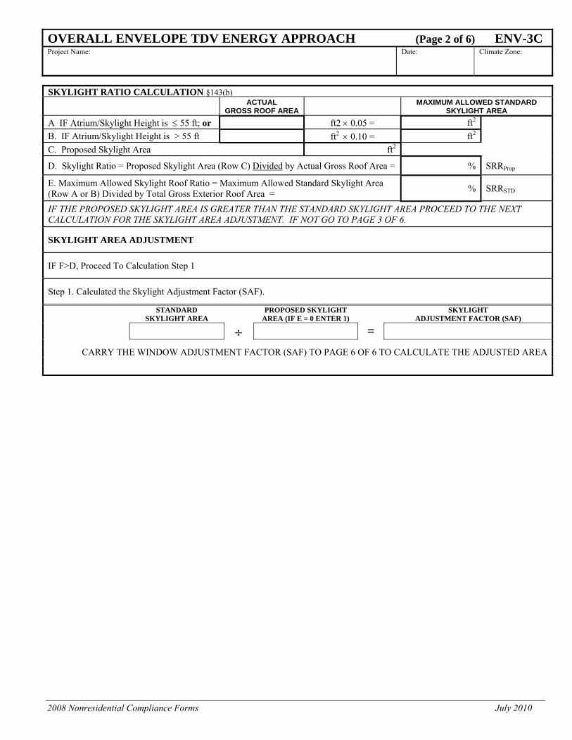
SKYLIGHT RATIO CALCULATION §143(b)
ACTUAL GROSS ROOF AREA
MAXIMUM ALLOWED STANDARD SKYLIGHT AREA
A IF Atrium/Skylight Height is ≤ 55 ft; or ft2 × 0.05 = ft2 B. IF Atrium/Skylight Height is > 55 ft ft2 × 0.10 = ft2 C. Proposed Skylight Area ft2
D. Skylight Ratio = Proposed Skylight Area (Row C) Divided by Actual Gross Roof Area = % SRRProp
E. Maximum Allowed Skylight Roof Ratio = Maximum Allowed Standard Skylight Area (Row A or B) Divided by Total Gross Exterior Roof Area = % SRRSTD
IF THE PROPOSED SKYLIGHT AREA IS GREATER THAN THE STANDARD SKYLIGHT AREA PROCEED TO THE NEXT CALCULATION FOR THE SKYLIGHT AREA ADJUSTMENT. IF NOT GO TO PAGE 3 OF 6.
SKYLIGHT AREA ADJUSTMENT
IF F>D, Proceed To Calculation Step 1
Step 1. Calculated the Skylight Adjustment Factor (SAF).
STANDARD SKYLIGHT AREA
PROPOSED SKYLIGHT AREA (IF E = 0 ENTER 1)
SKYLIGHT ADJUSTMENT FACTOR (SAF)
÷ =
CARRY THE WINDOW ADJUSTMENT FACTOR (SAF) TO PAGE 6 OF 6 TO CALCULATE THE ADJUSTED AREA

2008 Nonresidential Compliance Forms July 2010
OVERALL ENVELOPE TDV ENERGY APPROACH (Page 3 of 6) ENV-3C Project Name:
Date: Climate Zone:
TDV for the Standard Design Building, See Reference Nonresidential Appendix NA5.2
Occupancy Type and Coefficients Tables Nonresidential, See Table NA5-3 24-Hour Use, See Table NA5-4 Retail, See Table NA5-5
A B C D E F G H I J K L M
Assembly Type1 Orientation
Number Of Like
Assembly Type4
Roofs or Floor Mass
Type5
Exterior Surface
Area Fenetration
Type
Criteria Coefficients for9
Standard TDV Energy10
U-factor SHGC VT
U-factor6 SHGC7 VT8 Csu,i Css,i Cst,i
Sum of Total Standard Design1. Indicate type of assembly for the Envelope (e.g. Wall, Floor, Roof, Window, Skylight & Door). One assembly type for each row. 2. Enter the area of each different assembly. 3. Enter the type of fenestration; M=Manufactured, SB=Site-built, SK= Skylight and F=Fabricated. 4. Grouping of like assemblies in the same orientation is allowed. Iindicate the number in column E. 5. Enter Roofs, Floors, Walls,and for Mass Walls the catergories are light mass(HC<7), medium mass (7<=HC,15), and heavy mass (HC>=15). 6. Standard Design U-factor are from Table 143-A, B or C. 7. Standard Design SHGC are from Table 143-A, B or C. Enter “0” if not applicable for each skylight. Note: Not all vertical windows have an overhang then assume SHGC as value entered. 8. To calculate the fenestration standard design VT in Column I. Multiply Column H by 1.2. 9. Coefficients for; U-factor (Csu,i), SHGC (Css,i), and VT(Cst,I, can be found in Table NA5.2, through Table NA5.5 of the Reference Nonresidential Appendices NA5. The Coefficient for SHGC
and VT are only enter for the fenestration products. Enter “0” when not applicable.
10. Calculate the TDV Standard Design for for each Envelope Assembly Type: TDVStd = Column C x [Column E x ((U-factorSi x CSui) + (SHGCSi x CSsi) + (VTSi x CSti))] for each Assembly Type. See Nonresidential Manual Examples in Section 3.7.1 for details.

2008 Nonresidential Compliance Forms July 2010
OVERALL ENVELOPE TDV ENERGY APPROACH (Page 4 of 6) ENV-3C Project Name:
Date: Climate Zone:
TDV for the Proposed Design Building, See Reference Nonresidential Apendix NA5.3
Occupancy Type and Coefficients Tables Nonresidential, See Table NA5-3 24-Hour Use, See Table NA5-4 Retail, See Table NA5-5
A B C D E F G H I J K L M N
Assembly Type1 Orientation2
Number Of Like
Assembly Type2A
Total Exterior Surface Area3
Fenestration
Type4
Criteria Coefficients for Proposed TDV
Energy11 U- factor8 SHGC8 VT8 Cool Roof 9 Overhang10
U-factor 5 SHGC6 VT7 Csu,i CSs,i Ct,i MCR MOH
Total Proposed Design12
Proposed ≤ Standard
1. Indicate type of assembly for the Envelope (e.g. Wall, Floor, Roof, Window, Skylight & Door). One assembly type for each row. 2. Indicate the orientation for walls, doors & windows. 2A. Note: Grouping of like assemblies in the same orientation is allowed. Enter the number in column C. 3. Indicate the Exterior Surface Area of the Assembly for that one assembly or if like assemblies then the total surface area of all assemblies in the same orientation. 4. Enter the type of fenestration; M=Manufactured, SB=Site-built, SK= Skylight and F=Fabricated. 5. Proposed Design U-factor are from Table 143-A, B or C for the appropriate assembly type. 6. Proposed Design SHGC are from Table 143-A, B or C. Enter “0” if not applicable. Note: Not all vertical windows have an overhang then assume SHGC as value entered. 7. To calculate the fenestration proposed design VT in Column H. Multiply Column G by 1.2.
8. Coefficients for; U-factor (Csu,i), SHGC (Css,i), and VT(Cst,I, can be found in Table NA5.2, through Table NA5.5 of the Reference Nonresidential Appendices NA5. The Coefficient for SHGC and VT are only entered for the fenestration products. Enter “0” when not applicable.
9. Calculate the Cool Roof, MCR, first by using the next page (Page 5 of 6). Enter the value in the Proposed Column L. 10. Calculate the Overhang MOH on the next page (Page 5 of 6). Enter the value in the Proposed Column M. 11. The Proposed TDV energy use for all assemblies other than roofs must be equal to or less than Standard TDV in Page 3 of 6. Therfore; TDVP = Column D x [(U factor x CSu) + (CRui x URi x
MCRi) + (SHGCP x CSsi x MOH ) + (VTP x CSt)] Enter the calculated value in Column N. 12. Sum up all the Proposed TDV Energy in Column N and enter value in the cell. Similarly enter the sum of all Standard TDV Energy and compare. Proposed must be ≤ to the Standard.

2008 Nonresidential Compliance Forms July 2010
OVERALL ENVELOPE TDV ENERGY APPROACH (Page 5 of 6) ENV-3CCool Roof Multiplier (MCR) PROJECT NAME DATE
Occupancy Type and Coefficients Tables
Nonresidential, See Table NA5-3
24-Hour Use, See Table NA5-4
Retail, See Table NA5-5
Climate Zone:
Coefficients of Calculation
A B C D E F G
Reflectance Emittance
Proposed Aged Solar
Reflectance
Standard Aged Solar
Reflectance1
Proposed Thermal
Emittance
Standard Thermal
EmittanceCool Roof Multiplier2
CRef CEmit ρaged prop ρaged std εprop εstd MCR,I
Enter multiplier in Page 4 of 6 Column L.
Excerpt from Table NA5-2. Where: Standard design values for Solar Reflectance and Thermal Emittance.
Standard Aged Solar Reflectance (Column D)
Standard Thermal
Emittance (Column F)
Low-Rise, Low-Sloped, CZ2 through CZ15 0.55 0.75
Low-Rise, Low-Sloped, CZ1 and CZ16 0.10 0.75
High-Rise, Low-Sloped, CZ10 through CZ15 0.55 0.75
High-Rise, Low-Sloped, CZ1-9 and CZ16 0.10 0.75
Steep-Sloped, CZ2 through CZ15 0.25 0.75
Steep-Sloped, all other 0.10 0.75
1. Proposed Aged Design Solar Reflectance; ρaged prop = (0.7 x ρinit prop) +0.06, Where (ρinit prop) reflectance value is found in the CRRC Directory. Enter results of the Cool Roof Multiplier equation in footnote 2. 2. Cool Roof Multiplier McR,I = 1 + CRef x (ρaged prop - ρaged std) + CEmit x (εprop – εstd) or 1+ Col A x (Col C - Col D) + Col B x (Col E – Col F)
Overhang Multiplier (MOH) Occupancy Type and Coefficients Tables
Nonresidential, See Table NA5-3
24-Hour Use, See Table NA5-4
Retail, See Table NA5-5
Climate Zone:
Coefficients of Fenestration Overhang Calculation A B C D E F G
Overhang Orientation
1st Projection
Factor1
2nd Projection
Factor1
Horizontal Projection
(ft2)
Vertical Distance
(ft2) Projection
Factor2 Overhang Multiplier3
ai bi H V PF MOH,I
Enter multiplier in Page 4 of 6 Column M.
1. Where: ai and bi are the coefficients for the overhang projection factor (see tables) and is climate zone dependent. 2. PF= H/V (Horizontal (H) projection of the overhang from the surface of the window in feet, but no greater than V and the Vertical (V) distance from the window sill to the bottom of the overhang, in feet.) Enter results in Column F. 3. MOH,I = 1 + (ai x PFi) + bi x PFi
2 . Enter results in Column G.

2008 Nonresidential Compliance Forms July 2010
OVERALL ENVELOPE TDV ENERGY APPROACH (Page 6 of 6) ENV-3C PROJECT NAME DATE
WINDOW AREA ADJUSTMENT CALCULATIONS
A B C D E F G
WINDOW ADJUSTMENT
ADJUSTED WINDOW
ADJUSTED WALL
WALL NAME ORIENTATION GROSS AREA
DOOR AREA
WINDOW FACTOR AREA AREA (e.g. Wall-1, Wall-2) N E S W AREA (From Page 1of 6) (D×E) B-(F+C)
TOTALS:
SKYLIGHT AREA ADJUSTMENT CALCULATIONS A B C D E F
ROOF NAME GROSS SKYLIGHT SKYLIGHT ADJUSTMENT
FACTOR
ADJUSTED SKYLIGHT AREA
ADJUSTED ROOF AREA
(e.g. Roof-1, Roof-2) AREA AREA (From Page 2 of 6) (C×D) (B - E)
TOTALS:

2008 Nonresidential Compliance Forms August 2009
INSTALLATION CERTIFICATE (Part 1 of 2) ENV-INSTPROJECT NAME: DATE:
____________________
Building Permit
____________________ Checked by/Date
Enforcement Agency Use
PROJECT ADDRESS:
GENERAL INFORMATION DATE OF BUILDING PERMIT
PERMIT #
BUILDING TYPE Nonresidential
High-Rise Residential Hotel/Motel Guest Room
PHASE OF CONSTRUCTION New Construction Addition Alteration Unconditioned
If more than one person has responsibility for building construction, each person shall prepare and sign an Installation Certificate document applicable to the portion of construction for which they are responsible; alternatively, the person with chief responsibility for construction shall prepare and sign the Installation Certificate document(s) for the entire construction. DECLARATION STATEMENT • I certify under penalty of perjury, under the laws of the State of California, the information provided on this form is true and correct. • I am eligible under Division 3 of the Business and Professions Code to accept responsibility for construction, or an authorized
representative of the person responsible for construction (responsible person). • I certify that the installed features, materials, components, or manufactured devices identified on this certificate (the installation)
conforms to all applicable codes and regulations, and the installation is consistent with the plans and specifications approved by the enforcement agency.
• I reviewed a copy of the Certificate of Compliance approved by the enforcement agency that identifies the specific requirements for the installation. I certify that the requirements detailed on the Certificate of Compliance that apply to the installation have been met.
• I will ensure that a completed, signed copy of this Installation Certificate shall be posted, or made available with the building permit(s) issued for the building, and made available to the enforcement agency for all applicable inspections. I understand that a signed copy of this Installation Certificate is required to be included with the documentation the builder provides to the building owner at occupancy.
Company Name:
Responsible Person's Name: Responsible Person's Signature:
Lic.# Date Signed: Position With Company:
SCOPE OF RESPONSIBILITY Enter the date of approval by enforcement agency of the Certificate of Compliance that provides the specifications for the energy efficiency measures for the scope of responsibility for this Installation Certificate:
Date:
In the table below identify all applicable construction documents that specify the requirements for the scope of responsibility for this Installation Certificate.
Document Title or Description Applicable Sheets or Pages, Tables, Schedules, etc. Date Approved By the Enforcement
Agency

2008 Nonresidential Compliance Forms August 2009
INSTALLATION CERTIFICATE (Part 2 of 2) ENV-INST
In the table below identify all applicable construction documents that specify the requirements for the scope of responsibility reported by this Installation Certificate (continued).
Document Title or Description Applicable Sheets or Pages, Tables, Schedules, etc. Date Approved By the Enforcement
Agency