CITY OF MILPITAS - Californiamlp-010.ci.milpitas.ca.gov/_pdfs/bld_permit_sr_res_water_heater.pdf ·...
28
RH Water Heater Page 1 of 13 1/01/15 CITY OF MILPITAS Building & Safety Department 455 E. Calaveras Blvd. Milpitas, CA 95035 408-586-3240 www.ci.milpitas.ca.gov RESIDENTIAL WATER HEATER 1. PERMIT INFORMATION: ! The replacement of an existing or installation of a new water heater requires a Permit. ! A Permit may be issued only to a State of California Licensed Contractor with the proper license classification or the Homeowner. ! If the work is performed by the Homeowner personally or by his/her workers, and an inspection indicates the work cannot be completed satisfactorily, then a licensed contractor must perform the work. ! If the Homeowner hires workers, State Law requires the Homeowner to obtain Worker’s Compensation Insurance. Proof of this insurance is required prior to inspection. 2. INSTALLATION REQUIREMENTS: ! Building Codes: All work must comply with the 2013 California Residential Code (CRC) or 2013 California Building Code, 2013 California Electrical Code (CEC), 2013 California Mechanical Code (CMC), 2013 California Plumbing Code (CPC), 2013 California Energy Code (CEnC), 2013 California Green Building Code and 2014 Milpitas Municipal Code (MMC). ! Refer to the “Water Piping” handout for detailed information regarding replacement of water piping and insulation requirements of new hot water piping. ! All pipe, pipe fittings, traps, fixtures, material, and devices used in a plumbing system shall be listed or labeled (third-party certified) by an approved listing agency (CPC 301.1.1). ! Listed water heaters shall be installed in accordance with their listings and the manufacturer’s instructions (CPC 505.3.1). ! The minimum capacity for water heaters shall be in accordance with the first hour rating (this can be found on the “Energy Guide” label on the heater) as follows: (CPC 501.0) Number of Bathrooms 1 to 1.5 2 to 2.5 3 to 3.5 Number of Bedrooms 1 2-3 2 3-4 5 3 4-6 First Hour Rating, Gallons 42 54 54 67 80 67 80 ! Location: • A fuel burning (gas) water heater may be installed in a closet located in a bathroom or bedroom if installed in accordance with CPC Section 505.1. • Water heaters, except direct vent type, shall be located as close as practical to the vent (CPC 505.2). • Clearances shall not be such as to interfere with combustion air, draft hood clearance and relief, and accessibility for servicing. (CPC 505.3.1)
Transcript of CITY OF MILPITAS - Californiamlp-010.ci.milpitas.ca.gov/_pdfs/bld_permit_sr_res_water_heater.pdf ·...

RH Water Heater Page 1 of 13 1/01/15
CITY OF MILPITAS Building & Safety Department
455 E. Calaveras Blvd. Milpitas, CA 95035
408-586-3240 www.ci.milpitas.ca.gov
RESIDENTIAL
WATER HEATER
1. PERMIT INFORMATION:
! The replacement of an existing or installation of a new water heater requires a Permit.
! A Permit may be issued only to a State of California Licensed Contractor with the proper license classification or the Homeowner.
! If the work is performed by the Homeowner personally or by his/her workers, and an inspection indicates the
work cannot be completed satisfactorily, then a licensed contractor must perform the work.
! If the Homeowner hires workers, State Law requires the Homeowner to obtain Worker’s Compensation Insurance. Proof of this insurance is required prior to inspection.
2. INSTALLATION REQUIREMENTS:
! Building Codes: All work must comply with the 2013 California Residential Code (CRC) or 2013 California Building Code, 2013 California Electrical Code (CEC), 2013 California Mechanical Code (CMC), 2013 California Plumbing Code (CPC), 2013 California Energy Code (CEnC), 2013 California Green Building Code and 2014 Milpitas Municipal Code (MMC).
! Refer to the “Water Piping” handout for detailed information regarding replacement of water piping and
insulation requirements of new hot water piping.
! All pipe, pipe fittings, traps, fixtures, material, and devices used in a plumbing system shall be listed or labeled (third-party certified) by an approved listing agency (CPC 301.1.1).
! Listed water heaters shall be installed in accordance with their listings and the manufacturer’s instructions (CPC
505.3.1).
! The minimum capacity for water heaters shall be in accordance with the first hour rating (this can be found on the “Energy Guide” label on the heater) as follows: (CPC 501.0)
Number of Bathrooms 1 to 1.5 2 to 2.5 3 to 3.5 Number of Bedrooms 1 2-3 2 3-4 5 3 4-6 First Hour Rating, Gallons 42 54 54 67 80 67 80
! Location:
• A fuel burning (gas) water heater may be installed in a closet located in a bathroom or bedroom if installed in
accordance with CPC Section 505.1.
• Water heaters, except direct vent type, shall be located as close as practical to the vent (CPC 505.2).
• Clearances shall not be such as to interfere with combustion air, draft hood clearance and relief, and accessibility for servicing. (CPC 505.3.1)

RH Water Heater Page 2 of 13 1/01/15
Milpitas Building & Safety Department Water Heater
! General requirements:
• Water heaters shall be anchored or strapped to resist horizontal displacement due to earthquake motion. Straps shall be located within the top 1/3 of the water heater unit and one within the bottom 1/3. The bottom strap must be located at least 4" above the water heater controls. (CPC 508.2)
• Water heaters supported on the ground shall rest on level concrete or other approved base extending not less
than three (3) inches above the adjoining ground level (CPC 508.3).
• Water heaters located in a garage, or in an adjacent space opening into the garage that is not part of the living area, must be elevated so the burners and burner-ignition devices are at least 18" above the garage floor surface, unless the heater is listed as flammable vapor ignition resistant (FVIR) (CPC 508.14).
• Heater shall be located or protected so it is not subject to physical damage by a moving vehicle (CPC 508.14).
To resist a force from a 6,500 lb vehicle traveling at 5 mph, it will require a 6” concrete filled steel pipe installed 36” above the floor surface and imbedded in a 36” deep 18” square footing.
• Installer shall leave the manufacturer’s installation, operating, and maintenance instructions in a location on
the premises where they will be readily available for reference and guidance to the inspector, service personnel, and the owner or operator (CPC 508.26).
• Water heaters installed outdoors shall be listed for outdoor installation or provided with protection to the
degree the environment requires. Appliances listed for outdoor installation shall be installed in accordance with its listing. (CPC 508.27)
• Water heaters installed on roofs shall be installed in accordance with CPC Section 509.0.
• Water heaters installed where damage to building materials could occur from a leaking water heater, a water-
tight pan of corrosion-resistant materials shall be installed beneath the heater with not less than a ¾ inch drain to an approved location (CPC 508.4). The end of the drain should be in a location that will draw attention to the need for determining the cause of the leak.
• Dielectric unions shall be used at all points of connection where there is a dissimilarity of materials (CPC
316.2.4).
! Tankless water heaters shall be listed by an approved testing agency (UL, IAPMO, etc.) and be installed in accordance with it’s listing and the manufacturer’s requirements. If replacing an existing tank heater with a tankless, it is likely the gas piping will have to be replaced with a larger pipe run back to the meter. Piping shall be sized and installed in accordance with CPC Chapter 12. Some tankless heaters also require an electrical connection and an electrical permit may be required.
! Pressure regulator - where the water pressure is in excess of 80 psi, an approved type pressure regulator preceded
by an adequate strainer. The regulator and strainer shall be accessible, protected from freezing, and shall have the strainer readily accessible for cleaning without removing the regulator or strainer body or disconnecting the supply piping. An approved expansion tank shall be installed in the cold water distribution piping downstream of each such regulator. (CPC 608.2)

RH Water Heater Page 3 of 13 1/01/15
Milpitas Building & Safety Department Water Heater
! Expansion Tank - any water system provided with a check valve, backflow preventer, pressure regulator or any other normally closed device that prevents dissipation of building pressure back into the water main shall be provided with an approved, listed, and adequately sized expansion tank or other approved device having a similar function to control thermal expansion. Such expansion tank or other approved device shall be installed on the building side of the check valve, backflow preventer, or other device and shall be sized and installed in accordance with the manufacturer’s recommendation (usually between the cold water shut off and the water heater inlet). Due to the weight of the tank full, it should be mounted to the building structure. (CPC 608.3)
! Grounding and bonding - metal water (hot and cold) and gas piping systems installed in or attached to a building
or structure shall be bonded to the service equipment enclosure, the grounded conductor at the service, the grounding electrode conductor where of sufficient size, or to the one or more grounding electrodes used in accordance with CEC Section 250.104.
! Heaters installed in attics shall comply with the following: (CPC 509.4)
• An attic access opening and passageway shall be installed that is at least as large as the largest component of
the appliance but not less than 22w inches x 30 inches.
• Where the height of the passageway is less than 6 feet, the distance from the access opening to the appliance shall not exceed 20 feet.
• The passageway shall be unobstructed and shall have a solid flooring not less than 24 inches wide.
• A level working platform not less than 30 inches by 30 inches shall be provided in front of the service side of
the heater.
• A permanent 120 volt receptacle outlet and a lighting fixture shall be installed near the appliance. The switch controlling the lighting fixture shall be located at the entrance to the passageway.
• If heater is installed on top of ceiling framing, with the total weight not exceeding 400 lbs, then, as a
minimum: (Policy #BDP-BLG04)
o Water heater shall be located on a ¾” plywood platform attached to the ceiling joists with #10 wood screw or 8d penny nails 6” o.c. at the plywood panel edges and 12”o.c. at intermediate joists.
o If seismic strapping to the adjacent walls is not possible, provide strapping to the ceiling joists below.
Use ¾” x 24 gauge perforated plumbers tape encircling top 1/3 of the water heater. Provide minimum 3 evenly spaced diagonal braces to ceiling joists with similar plumbers tape or ½” diameter EMT conduit with flatten edges. Use 1/4” diameter x 1” round head machine bolt with washer and nut for bracing connections.
o Attach diagonal braces to wood ceiling joists with ¼” diameter x 3” long lag screws or 1/4” diameter x
2” machine bolts with washers and nut to metal joists.
o Protect plywood with corrosion-resistant pan as required by CPC 508.4 (see above).
! Water valves and unions:
• A fullway valve shall be installed on the cold water supply pipe to each water heater at or near the water heater (CPC 605.2).
RH Water Heater Page 4 of 13 1/01/15
Milpitas Building & Safety Department Water Heater
• Valves shall be brass or other approved material. Each gate or ball valve shall be a fullway type with working parts of non-corrosive material. Valves shall meet the requirements of NSF 61, Standard for Drinking Water System Components, as referenced in Table 14-1. (CPC 605.1)
• A union shall be installed in the water supply piping not more than 12 inches of regulating equipment, water
heating, conditioning tanks, and similar equipment that requires service by removal or replacement (CPC 609.5).
! Water piping connectors:
• Listed flexible copper water connectors shall be installed in readily accessible locations, unless otherwise
listed (CPC 604.4).
• Flexible corrugated connectors of copper or stainless steel shall be limited to 24 inches in length (CPC 604.12).
• Flexible metallic water heater connectors or reinforced flexible water heater connectors connecting water
heating to the piping system shall be in compliance with the applicable standards referenced in Table 14-1 (CPC 604.14).
! Relief valves:
• All storage water heaters shall have an approved, listed, adequately sized combination pressure and
temperature relief valve (CPC 608.3).
• The installation of temperature, pressure, and vacuum relief devices or combinations thereof, and automatic gas shutoff devices, shall be installed in accordance with their listings and the manufacturer’s instructions. A shutoff valve shall not be placed between the relief valve and the water heater or on discharge pipes between such valves and the atmosphere. (CPC 505.6).
• Relief valves shall be provided with a drain, not smaller than the relief valve outlet, of galvanized steel, hard-
drawn copper piping and fittings, CPVC or listed relief valve drain tube with fittings that will not reduce the internal bore of the pipe or tubing (straight lengths as opposed to coils) and shall extend from the valve to the outside of the building, with the end of the pipe not more than two feet nor less than 6 inches above ground or the flood level of the area receiving the discharge and pointing downward. Such drains shall be permitted to terminate at other approved locations (such as a garage floor if the floor slopes to drain and will not cause damage). Relief valve drains shall not terminate in a building’s crawl space. No part of such drain pipe shall be trapped or subject to freezing. The terminal end of the drain pipe shall not be threaded. (CPC 608.5)
• Most manufacturers allow a maximum of four 90 degree elbows and a maximum length 30 feet.
• Discharge from a relief valve into a water heater pan shall be prohibited (CPC 508.5).
• Where a hot-water storage tank or an indirect water heater is located at an elevation above the fixture outlets
in the hot-water system, a vacuum relief valve shall be installed on the storage tank or heater (CPC 608.7).
! Gas piping and gas shut-off valves:
• New gas piping must be installed back to the meter or calculations must be provided to show the existing piping is adequately sized.
RH Water Heater Page 5 of 13 1/01/15
Milpitas Building & Safety Department Water Heater
• It is the responsibility of the installer to verify that the new or existing gas supply is correctly sized before installation. Refer to the separate handout “Natural Gas Piping” for additional information.
• Gas connectors must comply with CPC Section 1212.0. Listed flexible gas connectors in compliance with
CSA Z21.24, Standard for Connectors for Gas Appliances may be used if installed in accordance with their listing. Connectors must be located completely in the same room as the appliance.
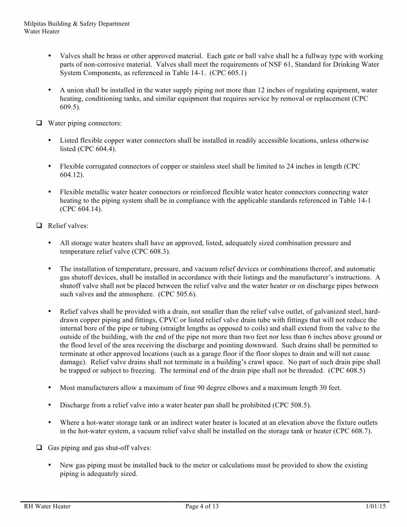
• An approved Excess Flow Gas Shut-off Device (non-motion sensitive) shall be installed at the gas fuel
appliance outlet when replacing any existing or installing any new gas fuel appliance. The Excess Flow Device shall be installed between the shutoff valve and the connector (see diagram page 7 not the photo below). (MMC II-170-2.00)
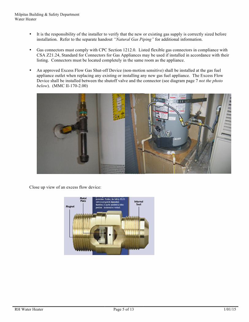
Close up view of an excess flow device:

RH Water Heater Page 6 of 13 1/01/15
1/01/15
Milpitas Building & Safety Department Water Heater
• An approved Seismic Gas Shut-off Device (motion sensitive) or an approved Excess Flow Gas Shut-off Device
(non-motion sensitive) shall be installed downstream of the gas utility meter (after PG&E service tee), but upstream of any appliances, when providing alteration or addition to the existing gas fuel line. (MMC II-170-2.00)
• Automatic Gas Shut-off Devices shall be installed by a contractor licensed in the appropriate classification by the State of California and in accordance with the manufacturer’s instructions.
• Seismic Gas Shut-off Devices (motion sensitive) must be mounted rigidly to the exterior of the building or
structure containing the fuel gas piping. This requirement need not apply if the Building and Safety Department determines that the Seismic Gas Shut-off Device (motion sensitive) has been tested and listed for an alternate method of installation.
• Both Seismic Gas Shut-off Devices (motion sensitive) and Excess Flow Gas Shut-off Devices (non-motion
sensitive) must be certified by the Office of State Architect and be listed by an approved listing and testing agency such as IAS, IAPMO, UL or the Office of State Architect. A current list of State Architect approved devices can be located at http://www.dgs.ca.gov/dsa/Programs/programCert/gasshutoff.aspx.
• Both Seismic Gas Shut-off Devices (motion sensitive) and Excess Flow Gas Shut-off Devices (non-motion
sensitive) must have a thirty (30) year warranty which warrants that the valve or device is free from defects and will continue to operate properly for thirty (30) years from the date of installation.
• Where Automatic Gas Shut-off Devices are installed voluntarily or as required by code, they shall be maintained
for the life of the building or structure or be replaced with a valve or device complying with the requirements of this section.

RH Water Heater Page 7 of 13 1/01/15
1/01/15
Milpitas Building & Safety Department Water Heater
• Where a sediment trap is not incorporated as a part of the gas appliance, a sediment trap shall be installed as close to the inlet of the appliance as practical at the time of equipment installation. The sediment trap shall be either a tee fitting with a capped nipple in the bottom outlet, as illustrated below, or other device recognized as an effective sediment trap. Trap shall be installed after shutoff valve to allow for draining. Sediment traps are not required on illuminating appliances, ranges, clothes dryers, decorative vented appliances for installation in vented fireplaces, gas fireplaces, and outdoor grills. (CMC 1312.6.3)
! Combustion air:
• Gas appliances of other than natural draft design and other than Category I vented appliances shall be provided with combustion, ventilation, and dilution air in accordance with the appliance manufacturer’s instructions (CPC 507.1.1). Most water heaters vent by gravity, their flue gases are lighter than the air in the environment in which the combustion occurs so they naturally rise up in a vent that is open to the atmosphere at the top. The open draft hood on the top of the water heater allows additional air to dilute the flue gases. Insufficient combustion air is hazardous. If there is not sufficient oxygen to fully burn the fuel at the correct temperature, deadly carbon monoxide will also be a product of combustion. If the air pressure in the water heater space is lower than that in the vent, products of combustion might “spill” out of the draft hood and enter the interior environment.
• Makeup air requirements for the operation of exhaust fans, kitchen ventilation systems, clothes dryers, and
fireplaces shall be considered in determining the adequacy of a space to provide combustion air requirements (CPC 507.1.4).
• Combustion air must be provided per CPC Section 507.0. When the appliance is located in a large room or space
(e.g. garage) the combustion air may come from that area. When located in a closet, combustion air must be provided by one or more openings between the closet and a large room or space, directly to the outside, to an area that communicates directly with the outside, or a combination of these. The following are minimum opening requirements:

RH Water Heater Page 8 of 13 1/01/15
1/01/15
Milpitas Building & Safety Department Water Heater
o Indoor air:
" All air from indoors by infiltration (appliance in same room) – the room must have a minimum 50 cubic feet per 1,000 Btu/hour of all appliances. Indoor rooms must have sufficient infiltration from the outdoors to continuously replenish the indoor air. The rate of infiltration is dependent on the number and size of gaps and cracks around openings in the building. Buildings of Unusually Tight Construction (less than 40% air changes per hour) require calculations of the infiltration rate (CPC 507.2)
" Openings used to connect indoor spaces on the same story – each opening shall have a free area of not
less than 1 square inch/1,000 Btu/hour of the total input rating of all gas appliances in the space, but not less than 100 square inches. One opening shall commence within 12 inches of the top, and one opening shall commence within 12 inches of the bottom of the enclosure. The minimum dimension of the air openings shall not be less than 3 inches. (CPC 507.3)
" Openings used to connect indoor spaces on different stories – the volumes of spaces in different stories
shall be considered as communicating spaces where such spaces are connected by one or more openings in doors or floors having a total free area of not less than 2 square inches/1,000 Btu/hour of the total input rating of all gas appliances in the space (CPC 507.3)
o Outdoor air – Outdoor combustion air shall be provided through opening(s) to the outdoors in accordance
with the following. The minimum dimension of the air opening(s) shall not be less than 3 inches. (CPC 507.4)
" Two permanent openings, one within 12 inches of the top and one within 12 inches of the bottom of the
enclosure. The openings shall communicate directly, or by ducts, with the outdoors or spaces that freely communicate with the outdoors as follows:
# Where directly communicating with the outdoors or where communicating through vertical ducts,
each opening shall have a free area of not less than 1 square inch/4,000 Btu/hour of total input rating of all appliances in the enclosure.
# Where communicating with the outdoors through horizontal ducts, each opening shall have a free area
of not less than 1 square inch/2,000 Btu/hour of total input rating of all appliances in the enclosure.
" One permanent opening, commencing within twelve inches of the top of the enclosure. The appliance shall have clearances of not less than 1 inch from the sides and back and 6 inches from the front of the appliance. The opening shall directly communicate with the outdoors or shall communicate through a vertical or horizontal duct to the outdoors or spaces that freely communicate with the outdoors and shall have a minimum free area of:
# 1 square inch/3,000 Btu/hour of total input rating of all appliances in the enclosure, and not less than
the sum of the areas of all vent connectors in the space.
o Combination of indoor and outdoor combustion air shall be in accordance with the following: (CPC 507.5)
" Indoor openings shall comply with the requirements for indoor air above.
" Outdoor openings shall comply with the requirements for outdoor air above.

RH Water Heater Page 9 of 13 1/01/15
1/01/15
Milpitas Building & Safety Department Water Heater
" The outdoor openings size shall be calculated as follows:
# The ratio of interior spaces shall be the available volume of communicating spaces divided by the required volume.
# The outdoor size reduction factor shall be one (1) minus the ratio of interior spaces.
# The minimum size of outdoor openings shall be the full size of outdoor openings calculated in
accordance with the requirements for outdoor air above (one or two openings), multiplied by the reduction factor. The dimension of air openings shall not be less than 3 inches.
o Mechanical air supply – where combustion air is provided by a mechanical air supply system, the combustion
air shall be supplied from outdoors at the minimum rate of 0.35 cubic feet/min per 1,000 Btu/hour for all appliances located in the space (CPC 507.7).
" Where exhaust fans are installed, additional air shall be provided to replace the exhausted air.
" Each of the appliances served shall be interlocked to the mechanical air supply system to prevent main
burner operation where the mechanical air supply system is not in operation.
" Where combustion air is provided by the building’s mechanical ventilation system, the system shall provide the specified combustion air rate in addition to the required ventilation air.
o Louvers, grilles and screens: (CPC 507.8)
" The required size of openings shall be based on the net free area of each opening. Where the free area
through a louver or grille is known, it shall be used. Where the design and free area are not known, it shall be assumed that wood louvers will have a 25 percent free area and metal louvers and grilles will have a 75 percent free area. Non-motorized louvers and grilles shall be fixed in the open position.
" Screens shall be not less than ¼ inch mesh.
" Motorized louvers shall be interlocked with the appliance.
o Combustion air ducts: (CPC 507.9)
" Ducts shall be of galvanized steel or a material having equivalent corrosion resistance, strength, and
rigidity. Within dwelling units, unobstructed stud and joist spaces shall be prohibited from conveying combustion air, provided that not more than one fireblock is removed.
" Ducts shall terminate in an unobstructed space, allowing free movement of combustion air to the
appliances.
" Ducts shall serve a single space.
" Ducts shall not service both upper and lower combustion air openings where both such openings are used. The separation between ducts serving upper and lower combustion air openings shall be maintained to the source of combustion air.
" Ducts shall not be screened where terminating in an attic space.

RH Water Heater Page 10 of 13 1/01/15
Milpitas Building & Safety Department Water Heater
" Intakes for combustion air ducts located exterior to the building shall have the lowest side of the combustion air intake openings located at least 12 inches vertically from the adjoining finished grade level.
" Horizontal upper combustion air ducts shall not slope downward toward the source of combustion air.
! Vents shall be as follows:
Note: See also Energy Code Section 150.0(n).
• A venting system shall be designed and constructed to develop a positive flow adequate to remove flue or vent
gases to the outside atmosphere (CPC 510.3.1). The venting system shall satisfy the draft requirements of the appliance in accordance with the terms of its listing and the manufacturer’s instructions (CPC 510.3.2). Refer to Table 5-18 for capacity of existing asbestos cement vent pipe.
• Type B gas vent is a vent for venting listed gas appliances with draft hoods and other Category I appliances listed
for use with Type B gas vents (CPC 502.9).
• Type L gas vent is a vent for venting appliances listed for use with type L vents and appliances listed for use with Type B gas vents (CPC 502.10).
• Single-wall metal pipe shall not be used as a vent in dwellings and residential occupancies (CPC 510.7.4.1).
• For sizing an individual gas vent for a single, draft-hood-equipped appliance, the effective area of the vent
connector and the gas vent shall be at least the area of the appliance draft hood outlet but no larger than seven times the draft hood outlet area [CPC 510.6.3.1(3)]. Vents for two draft-hood-equipped appliances shall be the size of the larger draft hood outlet area plus 50 percent of the smaller draft hood outlet area [CPC 510.6.3.1(4)].
• Type B or L vents shall extend in a generally vertical direction with offsets not exceeding 45 degrees, except that
a vent system having not more than one 60 degree offset shall be permitted. Any angle greater than 45 degrees from the vertical is considered horizontal. The total horizontal distance of a vent plus the horizontal vent connector serving draft-hood-equipped appliances shall into exceed 75 percent of the vertical height of the vent. (CPC 510.6.1.1)
• Type B and L vents shall terminate at least 5 feet in vertical height above the highest connected appliance draft
hood or flue collar (CPC 510.6.2.1).
• Screws, rivets and other fasteners shall not penetrate the inner wall of double wall vents (CPC 510.6.1.2).
• The vent passing through a roof shall extend through the entire roof flashing, roof jack, or roof thimble and be terminated with a listed termination cap (CPC 510.6.1).
• The vent shall terminate a minimum 12" (more if roof slope exceeds 6:12) above the roof (measured from the
high side of the roof where the vent passes through to the lowest discharge opening) or 2 feet above a vertical wall or similar obstruction within 8 feet. (CPC 510.6.2)
• A vent shall terminate at least 3 feet above a force air inlet located within 10 feet (CPC 510.6.2.6).
• A vent extending through an exterior wall shall not terminate adjacent to the wall or below eaves or parapets,
except as permitted in CPC 510.2.5 and 510.3.4.
• Direct vent appliances shall terminate in accordance with CPC 510.8.3.

RH Water Heater Page 11 of 13 1/01/15
Milpitas Building & Safety Department Water Heater
• Mechanical draft systems shall be installed in accordance with CPC 510.3.4.
• Vents serving gas appliances located on more than one floor shall be sized and installed in accordance with CPC Section 510.6.4.
• Vents must be supported and spaced in accordance with their listing and the manufacturer’s instructions (CPC
510.6.5)
! Vent connectors shall be installed as follows:
• A vent connector shall be used to connect the water heater to the vent, unless the vent connects directly to the heater (CPC 510.10.1).
• Vent connectors for listed gas appliances with draft hoods that are not installed in attics, crawl spaces, or other
unconditioned areas shall be: (CPC 510.10.2.4)
o Type B or L vent material. o Galvanized sheet steel at least 0.018 inches thick. o Aluminum (1100 or 3003 alloy or equivalent) sheet at least 0.027 inches thick. o Stainless steel sheet at least 0.012 inches thick. o Smooth interior wall metal pipe having resistance to heat and corrosion equal to or exceeding that of the
galvanized, aluminum or stainless material listed above. o Listed vent connector.
• Listed single-wall vent connectors may be used but must be located in the same room as the heater (CPC
510.7.4.3).
• Single wall metal pipe shall not originate in any unoccupied attic or concealed space (CPC 510.7.4.3).
• A vent connector shall not pass through any ceiling, floor, or fire-resistance-rated wall. A single-wall metal pipe shall not pass through any interior wall. A vent connector made of Type B material and serving a heater with a draft-hood may pass through walls if clearance to combustibles is maintained. (CPC 510.10.14)
• Where two or more openings are provided into one vent, the openings shall either be at different levels, or the
connectors shall be attached to the vertical portion of the vent at an angle of 45 degrees or less relative to the vertical. Where two or more connectors enter a common vent, the smaller connector shall enter at the highest level possible consistent with the available headroom or clearance to combustible material. Vent connectors serving natural draft venting appliances shall not be connected to a vent serving other appliances operating under positive static pressure. (CPC 510.10.4)
• The minimum clearances from single wall metal connectors and combustibles shall be 6”. The clearances from
Type B connectors shall be per its listing. (CPC 510.10.5)
• Connectors shall be installed so as to avoid turns or bends (CPC 510.10.6).
• Vent connector shall be as short as practical and the water heater located as close as practical to the vent. The maximum horizontal length of a single-wall connector shall be 75 percent of the height of the vent. The maximum horizontal length of a type B connector shall be 100 percent of the height of the vent. The maximum length of an individual connector for a vent system serving multiple appliances, from the appliance outlet to the junction with the common vent or another connector, shall be 100 percent of the height of the vent. (CPC 510.10.9)

RH Water Heater Page 12 of 13 1/01/15
Milpitas Building & Safety Department Water Heater
• Joints between sections of vent connector piping and connections to flue collars or draft hood outlets shall be fastened by sheet metal screws, in accordance with the manufacturer’s instructions, or other approved means (CPC 510.10.7).
• Vent connectors shall be installed without any dips or sags and shall slope upward toward the vent not less than
1/4 inch per foot (CPC 510.10.8).
• Vent connectors shall be supported for the design and weight of the material employed to maintain clearances and prevent physical damage and separation of joints (CPC 510.10.10).
• Vent connectors serving two draft-hood equipped appliances shall be at least the area of the larger vent connector
plus 50 percent of the areas of small flue collar outlets (CPC 510.10.3.4).
• Vent connector for an appliance with a single draft hood outlet shall be the size of the flue collar. The size of the connector when there is more than one outlet or more than one appliance served by a common connector shall be in accordance with CPC Section 511. (CPC 510.10.3)
3. ENERGY REQUIREMENTS:
! Water heaters may be installed only if the heater is in compliance with the requirements of the Appliance Efficiency Regulations of the California Energy Code. The Energy Commission's database of certified appliances is available at: www.energy.ca.gov/appliances/database/. [CEnC 110.3(b)]
! Storage gas water heaters with an energy factor (EF) equal to or less than the federal minimum standards shall be
externally wrapped with insulation having an installed thermal resistance of R-12 or greater [CEnC 150.0(j)1A].
o EF = 0.67 – (0.0019 x volume). o 30 gal = 0.0613 EF, 40 gal = 0.594 EF, 50 gal = 0.575 EF
! Unfired hot water tanks, such as storage tanks and backup storage tanks for solar water-heating systems, shall be
externally wrapped with insulation having an installed thermal resistance of R-12 or greater or have internal insulation of at least R-16 and a label on the exterior of the tank showing the insulation R-value. [CEnC 150.0(j)1B]
! The first 5 feet of hot and cold water pipes from the storage tank (or up to where the piping enters a wall or ceiling if
less than 5 feet), and all exposed piping if ¾ inch or larger, shall be insulated with a minimum 1” insulation [CEnC 150.0(j)2]
! Title 24 Energy Compliance Reports: The following installation forms must be filled out and given to the inspector
at time of final inspection:
• Single Dwelling Unit Hot Water System Distribution CF2R-PLB-02-E, or • Multifamily Central Hot Water System Distribution CF2R-PLB-01-E.
4. SMOKE ALARMS, CARBON MONOXIDE ALARMS & SPARK ARRESTERS:
! In single family and multi-family residences (including townhomes, condominiums and apartments), installation of smoke alarms, carbon monoxide alarms and spark arresters on all chimneys is required prior to the final inspection. Refer to the “Smoke Alarm, Carbon Monoxide Alarm and Spark Arrester Certificate” attached for detailed information.

RH Water Heater Page 13 of 13 1/01/15
Milpitas Building & Safety Department Water Heater 5. INSPECTION PROCEDURES:
! A final inspection is required after the water heater has been installed and all work completed. The Permit Card with the Energy Compliance Report forms completely filled out and attached, and the Approved Job Copy of the Drawings (if any) must be presented to the inspector. Permits expire 180 days after issuance or last inspection passed, whichever is the latest.
6. QUESTIONS:
! If you have any questions regarding your project contact the Building & Safety Department at (408) 586-3240


RH Smoke and CO Alarm Certificate Page 1 of 2 01/01/14
CITY OF MILPITAS Building & Safety Department
455 E. Calaveras Blvd. Milpitas, CA 95035
408-586-3240 www.ci.milpitas.ca.gov
SMOKE ALARM, CARBON MONOXIDE ALARM and
SPARK ARRESTER CERTIFICATE
This “Certificate” can be signed by the property owner and provided to the Building Inspector prior to final inspection if access to the interior of the dwelling for inspection of the smoke and carbon monoxide alarms is not possible and the permitted work being performed is exterior only (such as re-roofing, re-siding, patio covers, swimming pools and the like). In single family and multi-family residences (including townhomes, condominiums and apartments), installation of smoke alarms, carbon monoxide alarms and spark arresters is required prior to the final inspection as follows:
Smoke Alarms shall be listed and labeled in accordance with UL 217 and installed in accordance with the provisions of the code and the household fire warning equipment provisions of NFPA 72. Systems and components shall be California State Fire Marshal listed and approved. Alarms shall be tested and maintained in accordance with the manufacturer's instructions. Alarms that no longer function shall be replaced. Conventional ionization smoke alarms that are solely battery powered shall be equipped with a ten-year battery and have a silence feature. Alarms installed in one and two-family dwellings shall be replaced after 10 years from the date of manufacture marked on the unit, or if the date of manufacture cannot be determined. (CRC R314)
Smoke detection systems. Household fire alarm systems installed in accordance with NFPA 72 that include smoke alarms, or a combination of smoke detector and audible notification device installed as required for smoke alarms, shall be permitted. The household fire alarm system shall provide the same level of smoke detection and alarm as required for smoke alarms. Where a household fire warning system is installed using a combination of smoke detector and audible notification device(s), it shall become a permanent fixture of the occupancy and owned by the homeowner. The system shall be monitored by an approved supervising station and be maintained in accordance with NFPA 72. Location. Smoke alarms shall be installed in each sleeping room, outside each separate sleeping area in the immediate vicinity of the bedrooms and on each story of the dwelling. In dwellings or dwelling units with split levels and without an intervening door between the adjacent levels, a smoke alarm installed on the upper level shall suffice for the adjacent lower level provided that the lower level is less than one full story below the upper level. Apartment complexes and other multiple-dwelling complexes shall have a smoke detector installed in the common stairwells. For R-3.1 occupancies (Residential Care Facilities), refer to CBC Section 907.2.11.2. The installation of smoke alarms and smoke detectors shall also comply with the following requirements:
1. Smoke alarms shall not be located where ambient conditions, including humidity and temperature, are outside the limits specified by the manufacturer's published instructions.
2. Smoke alarms shall not be located within unfinished attics or garages or in other spaces where temperatures can fall below 40°F or exceed 100°F.
3. Where the mounting surface could become considerably warmer or cooler than the room, such as a poorly insulated ceiling below an unfinished attic or an exterior wall, alarms shall be mounted on an inside wall.
4. Smoke alarms shall be installed a minimum of 20 feet horizontal distance from a permanently installed cooking appliance, except Ionization smoke alarms with an alarm-silencing switch or Photoelectric smoke alarms shall be permitted to be installed 10 feet or greater from a permanently installed cooking appliance and Photoelectric smoke alarms shall be permitted to be installed greater than 6 feet from a permanently installed cooking appliance where the kitchen or cooking area and adjacent spaces have no clear interior partitions and the 10 foot distances would prohibit the placement of a required smoke alarm or smoke detector. Smoke alarms listed for use in close proximity to a permanently installed cooking appliance can be installed in accordance with their listing.
5. Smoke alarms shall be installed not less than a 3 foot horizontal distance from the door or opening of a bathroom that contains a bathtub or shower unless this would prevent placement of a smoke alarm required by the code.
6. Smoke alarms shall not be installed within a 36 inch horizontal path from the supply registers of a forced air heating or cooling system and shall be installed outside of the direct airflow from those registers.
7. Smoke alarms shall not be installed within a 36 inch horizontal path from the tip of the blade of a ceiling-suspended (paddle) fan.
8. Where stairs lead to other occupied levels, alarm shall be located so that smoke rising in the stairway cannot be prevented from reaching the alarm by an intervening door or obstruction.

RH Smoke and CO Alarm Certificate Page 2 of 2 01/01/14
Milpitas Building & Safety Department Smoke Alarm, Carbon Monoxide Alarm and Spark Arrester Certificate
9. For stairways leading up from a basement, alarms shall be located on the basement ceiling near the entry to the stairs.
10. For tray-shaped ceilings (coffered ceilings), alarms shall be installed on the highest portion of the ceiling or on the sloped portion of the ceiling within 12 inch vertically down from the highest point.
11. Smoke alarms installed in rooms with joists or beams shall comply with the requirements of NFPA 72, Section 17.7.3.2.4.
12. Heat alarms and detectors installed in rooms with joists or beams shall comply with the requirements of NFPA 72, Section 17.6.3.
Carbon Monoxide Alarms: An approved carbon monoxide alarm listed as complying with UL 2034, approved and listed by the California State Fire Marshal, installed and maintained in accordance with NFPA 720 and the manufacturer’s instructions shall be installed if they do not already exist in existing dwellings or sleeping units having a fossil fuel-burning heater or appliance, fireplace or an attached garage as follows: outside each separate dwelling unit sleeping area in the immediate vicinity of bedroom(s) and on every level of dwelling unit. Carbon monoxide detection systems that include carbon monoxide detectors and audible notification appliances, installed and maintained as required for carbon monoxide alarms and NFPA 720 shall be permitted. The carbon monoxide detectors shall be listed as complying with UL 2075. (CRC R315)
Power supply: Smoke and carbon monoxide alarms shall receive their primary power from the building wiring and shall be equipped with a battery back-up. Smoke alarms with integral strobes that are not equipped with battery backup shall be connected to an emergency electrical system. Smoke alarms shall emit a signal when the batteries are low. Smoke and carbon monoxide alarm wiring shall be directly connected to the permanent building wiring without a disconnecting switch other than as required for overcurrent protection. Smoke and carbon monoxide alarms are permitted to be solely battery operated (carbon monoxide alarms can also be plug-in with battery back-up) in existing buildings where no construction is taking place; in existing areas of buildings undergoing alterations or repairs that do not result in the removal of interior walls or ceiling finishes exposing the structure unless there is an attic or crawl space available which could provide access for building wiring without the removal of interior finishes; where repairs or alterations are limited to the exterior surfaces of dwellings, such as the replacement of roofing or siding, or the addition or replacement of windows or doors, or the addition of a porch or deck; or when work is limited to the installation, alteration or repairs of plumbing or mechanical systems or the installation, alteration or repair of electrical systems which do not result in the removal of interior wall or ceiling finishes exposing the structure: and, for carbon monoxide alarms, when other power sources recognized for use by NFPA 720 are used.
Interconnection: Where more than one smoke or carbon monoxide alarm is required to be installed within an individual dwelling or sleeping unit, the alarms shall be interconnected in such a manner that the activation of one alarm will activate all of the alarms in the individual unit, except interconnection is not required in buildings that are not undergoing alterations, repairs or construction of any kind; where alterations or repairs do not result in the removal of interior wall or ceiling finishes exposing the structure unless there is an attic or crawl space available which could provide access for interconnection without the removal of interior finishes and no previous method for interconnection existed; where repairs or alterations are limited to the exterior surfaces of dwellings, such as the replacement of roofing or siding, or the addition or replacement of windows or doors, or the addition of a porch or deck; or when work is limited to the installation, alteration or repairs of plumbing or mechanical systems or the installation, alteration or repair of electrical systems which do not result in the removal of interior wall or ceiling finishes exposing the structure. The alarm shall be clearly audible in all bedrooms over background noise levels with all intervening doors closed.
Spark arresters: When a permit has been issued and the value of the work exceeds $1,000, a spark arrester must be installed on all fireplace chimneys, if one does not already exist, per MMC Section II-3-2.06. Spark arresters shall be constructed in conformance with CRC Section 1003.9.2.
* CERTIFICATION *
I understand the above requirements and certify that I now have smoke alarms, carbon monoxide alarms and spark arrestors installed as required above.
HOMEOWNERS NAME (please print): _________________________________________________________________
ADDRESS: ________________________________________________________________________________________
SIGNATURE: ______________________________________________________________________________________
DATE: _______________________________ PERMIT NO. ______________________________________________

STATE OF CALIFORNIA
RESIDENTIAL ALTERATIONS CEC-CF1R-ALT-01-E (Revised 06/14) CALIFORNIA ENERGY COMMISSION
CERTIFICATE OF COMPLIANCE WATER HEATERS ONLY CF1R-‐ALT-‐01-‐E Prescriptive Residential Alterations (Page 1 of 2) Project Name: Date Prepared:
A. GENERAL INFORMATION 01 Project Name: 02 Date Prepared: 03 Project Location: 04 Building Front Orientation (deg or cardinal): 05 CA City: 06 Number of Altered Dwelling Units: 07 Zip Code: 08 Fuel Type: 09 Climate Zone: 10 Total Conditioned Floor Area (ft2): 11 Building Type 12 Slab Area (ft2) 13 Project Scope: :
G. WATER HEATING SYSTEMS (Section 150.2(b)1G)
01 02 03 04 05 06 07 08 09 10 11 12 13 14 15
Water Heating System
Identification or Name
Water Heating
System Type
Water Heater Type
# of Water Heaters
in system
Water Heater Storage Volume (gal)
Fuel Type
Rated Input Type
Rated Input Value
Heating Efficiency Type
Heating Efficiency Value
Standby Loss (%)
Exterior Insul. R-‐Value
Back-‐Up Solar Savings Fraction
Central DHW System Distribution Type
Dwelling Unit DHW System
Distribution Type
CA Building Energy Efficiency Standards -‐ 2013 Residential Compliance June 2014

STATE OF CALIFORNIA
RESIDENTIAL ALTERATIONS CEC-CF1R-ALT-01-E (Revised 06/14) CALIFORNIA ENERGY COMMISSION
CERTIFICATE OF COMPLIANCE CF1R-‐ALT-‐01-‐E Prescriptive Residential Alterations (Page 2 of 2) Project Name: Date Prepared:
DOCUMENTATION AUTHOR'S DECLARATION STATEMENT 1. I certify that this Certificate of Compliance documentation is accurate and complete. Documentation Author Name: Documentation Author Signature:
Company: Signature Date:
Address: CEA/ HERS Certification Identification (if applicable):
City/State/Zip: Phone:
RESPONSIBLE PERSON'S DECLARATION STATEMENT I certify the following under penalty of perjury, under the laws of the State of California:
1. The information provided on this Certificate of Compliance is true and correct. 2. I am eligible under Division 3 of the Business and Professions Code to accept responsibility for the building design or system design identified on this Certificate of Compliance (responsible
designer). 3. That the energy features and performance specifications, materials, components, and manufactured devices for the building design or system design identified on this Certificate of
Compliance conform to the requirements of Title 24, Part 1 and Part 6 of the California Code of Regulations. 4. The building design features or system design features identified on this Certificate of Compliance are consistent with the information provided on other applicable compliance documents,
worksheets, calculations, plans and specifications submitted to the enforcement agency for approval with this building permit application. 5. I will ensure that a registered copy of this Certificate of Compliance shall be made available with the building permit(s) issued for the building, and made available to the enforcement agency
for all applicable inspections. I understand that a registered copy of this Certificate of Compliance is required to be included with the documentation the builder provides to the building owner at occupancy.
Responsible Designer Name: Responsible Designer Signature:
Company : Date Signed:
Address: License:
City/State/Zip: Phone:
For assistance or questions regarding the Energy Standards, contact the Energy Hotline at: 1-‐800-‐772-‐3300.
CA Building Energy Efficiency Standards -‐ 2013 Residential Compliance June 2014

Minimum requirements for prescriptive alteration compliance can be found in Building Energy Efficiency Standards Section 150.2(b)1.
Instructions for sections with column numbers and row numbers are given separately.
If any part of the alteration does not comply, prescriptive compliance fails, in which case the performance compliance approach must be used in an attempt to achieve compliance.
A. GENERAL INFORMATION
Project Name: Identifying information, such as owner’s name. Date: Date of document preparation.
Project Location: Legal street address of property or other applicable identifying information. Compliance Method: Prescriptive.
CA City: Legal city/town of property.
Building Front Orientation: Leave blank
Zip Code: 5-‐digit zip code for the project location (used to determine climate zone). Number of Dwelling Units: 1 for single-‐family, 1 or more for multifamily.
Climate zone: 4.
Fuel Type: Natural Gas, Liquefied Propane Gas, or Electricity. NOTE: prescriptive compliance only allows electricity if existing appliances are electric and natural gas is not available in the building.
Building Type: Single Family (includes duplex), or Multi Family (a building that shares common walls and common floors or ceilings).
Total Conditioned Floor Area: Leave blank.
Project Scope: Water heating alteration.
Slab Area: Leave blank.
G. WATER HEATING SYSTEMS
Water heating compliance for an alteration is described in Section 150.2(b). For single dwelling a gas or propane water heater, with a storage tank of 60 gallons maximum or instantaneous (tankless) can be used. Dwelling Unit distribution systems are limited to Standard trunk and branch or demand recirculation for gas or propane water heater. Demand recirculation is not allowed for electric water heater. If there is no natural gas connected to the building, an electric water heater may be replaced with another electric water heater. However, changing from gas to electric is not allowed.. Multi-‐family central systems must use certified equipment as defined under Section 110.1 and 110.3.
CA Building Energy Efficiency Standards -‐ 2013 Residential Compliance June 2014
CERTIFICATE OF COMPLIANCE – DATA FIELD DEFINITIONS AND CALCULATIONS CF1R-‐ALT-‐01-‐E Prescriptive Residential Alterations (Page 1 of 2)

NOTE: If the proposed installation does not meet the requirements allowed specifically for alterations, use form CF1R-‐NCB-‐01 to document the water heater alteration.
1. Water Heating System Identification or Name: enter a unique name for the Water Heating System. 2. Water heating system type: Domestic Hot Water (DHW), Hydronic, Combined Hydronic, or Central. DHW is for domestic hot water, hydronic is
a water heating system used for space heating only; combined hydronic are when the water heater will provide both space conditioning and domestic hot water.
3. Water heater type. For non-‐central systems only Small Storage or Small Instantaneous are allowed. For central systems pick from Large Storage, Small Storage, Heat Pump, Boiler, Large Instantaneous, Small Instantaneous or Indirect.
4. Number of water heaters in system: In single-‐family and multi-‐family with water heaters in each dwelling units the value is 1. For multi-‐family central systems serving multiple dwelling units enter the total number of water heaters.
5. Water heater volume (gal): tank capacity in gallons. For individual water heaters for a dwelling unit this will be 60 gallons or less. If instantaneous, enter n/a. For multi-‐family central systems enter the total storage volume.
6. Fuel Type: Gas, Propane, Electric (Only if natural gas is not available) 7. Rated Input Type: Enter the equipment input rating type, for gas or propane fired units are Btuh, for electric fired system the units are kW. 8. Rated Input Value: Enter the numeric value of rated input. 9. Heating Efficiency Type: Energy Factor, AFUE, or Thermal Efficiency. From product literature or a California Energy Commission directory. 10. Heating Efficiency Value: Enter the value from product literature or a California Energy Commission directory 11. Standby Loss (percent): Applies only to large storage water heaters, Enter n/a for small storage or instantaneous water heaters. 12. Exterior Insulation R-‐Value: Enter the R-‐value if exterior insulation on the storage tank is installed 13. Back-‐up solar savings fraction: If compliance requires a back-‐up solar system, indicate the solar contribution (e.g., 0.30). External calculations
are required. 14. Central DHW Distribution System: For multi-‐family buildings with using a central distribution system a demand recirculation system with at
least two distribution loops must be installed. This requirement applies to any building with eight or more units. If the system is non-‐central or project is individual units enter n/a.
15. Dwelling Unit DHW Distribution Type: For a Central DHW this field shall be Standard. If non-‐central then pick from Standard, Demand Recirculation – Manual Control, Demand Recirculation – Sensor Control. If non-‐central electric water heater this must be Standard, no recirculation system shall be installed.
SIGNATURES
1. The person who prepared the CF1R will sign and complete the fields for their name, company (if applicable), address, phone number, certification information (if applicable), date and signature (may be electronic).
2. The person who is assuming responsibility for the project being built to comply with Title 24, Part 6, will complete the fields for their name, company (if applicable), address, phone number, license number (if applicable), date and signature (may be electronic).
CA Building Energy Efficiency Standards -‐ 2013 Residential Compliance June 2014
CERTIFICATE OF COMPLIANCE – DATA FIELD DEFINITIONS AND CALCULATIONS CF1R-‐ALT-‐01-‐E Prescriptive Residential Alterations (Page 2 of 2)

STATE OF CALIFORNIA
SINGLE DWELLING UNIT HOT WATER SYSTEM DISTRIBUTION CEC-CF2R-PLB-02-E (Revised 06/14) CALIFORNIA ENERGY COMMISSION
CERTIFICATE OF INSTALLATION CF2R-‐PLB-‐02-‐E Single Dwelling Unit Hot Water System Distribution (Page 1 of 6) Project Name: Enforcement Agency: Permit Number:
Dwelling Address: City Zip Code
A. General Information
01 Dwelling Unit Name B. Design Dwelling Unit Water Heating Systems Information This table reports the water heating system features that were specified on the registered CF1R compliance document for this project.
01 02 03 04 05 06 07 08 09 10 11 12 13 14
Water Heating System ID or
Name
Water Heating
System Type
Water Heater Type
# of Water Heaters
in system
Water Heater Storage Volume (gal)
Fuel Type
Rated Input Type
Rated Input Value
Heating Efficiency Type
Heating Efficiency Value
Standby Loss (%)
Exterior Insul. R-‐Value
Central DHW System Distribution Type
Dwelling Unit DHW System Distribution Type
C. Installed Dwelling Unit Water Heating Systems Information
01 02 03 04 05 06 07 08 09 10 11 12 13 14
Water Heating System ID or
Name
Water Heating
System Type
Water Heater Type
# of Water Heaters
in system
Water Heater Storage Volume (gal)
Fuel Type
Rated Input Type
Rated Input Value
Heating Efficiency Type
Heating Efficiency Value
Standby Loss (%)
Exterior Insul. R-‐Value
Central DHW System Distribution Type
Dwelling Unit DHW System
Distribution Type
D. Installed Water Heater Manufacturer Information
01 02 03 Water Heating
System ID or Name
Manufacturer
Model Number
Registration Number: Registration Date/Time: HERS Provider: CA Building Energy Efficiency Standards -‐ 2013 Residential Compliance June 2014

STATE OF CALIFORNIA
SINGLE DWELLING UNIT HOT WATER SYSTEM DISTRIBUTION CEC-CF2R-PLB-02-E (Revised 06/14) CALIFORNIA ENERGY COMMISSION
CERTIFICATE OF INSTALLATION CF2R-‐PLB-‐02-‐E Single Dwelling Unit Hot Water System Distribution (Page 2 of 6) Project Name: Enforcement Agency: Permit Number:
Dwelling Address: City Zip Code
E. MANDATORY MEASURES FOR ALL DOMESTIC HOT WATER DISTRIBUTION SYSTEMS 01 Equipment shall meet the applicable requirements of the Appliance Efficiency Regulations (Section 110.3(b)1). 02 Unfired Storage Tanks are insulated with an external R-‐12 or combination of R-‐16 internal and external Insulation. (Section 110.3(c)4).
03
The following pipes are insulated, to the thicknesses required by Table 120.3A, except for those sections of pipe that are subject to one of the exceptions below: (RA4.4.1)
• The first 5 feet (1.5 meters) of hot and cold water pipes from the storage tank. • All piping with a nominal diameter of 3/4 inch (19 millimeter) or larger. • All piping associated with a domestic hot water recirculation system regardless of the pipe diameter, except when cold water return is used in a demand
system. • Piping from the heating source to storage tank or between tanks. • Piping buried below grade. • All hot water pipes from the heating source to the kitchen fixtures.
The following sections of pipe do not have to be insulated: (RA4.4.1) • Piping installed in interior or exterior walls that is surrounded on all sides by at least 1 inch of insulation. • Piping installed in attics with a minimum of 4 inches (10 cm) of attic insulation on top • Piping that penetrates framing members shall not be required to have pipe insulation for the distance of the framing penetration. Metal piping that penetrates
metal framing shall use grommets, plugs, wrapping or other insulating material to assure that no contact is made with the metal framing. Insulation shall butt securely against all framing members.
04 Piping buried below grade must be installed in a water proof and non-‐crushable casing or sleeve that allows for installation, removal, and replacement of the enclosed pipe and insulation. (Section 150.0(j))
05 All elbows and tees shall be fully insulated. (RA4.4.1) 06 Where insulation is required, no piping shall be visible due to insulation voids, and all insulation shall fit tightly to the pipe. (RA4.4.1)
07
For Gas or Propane Water Heaters: Ensure the following are installed (Section 150.0(n)) 1. A 120V electrical receptacle is within 3 feet from the water heater and accessible with no obstructions 2. A Category III or IV vent, or a Type B vent with straight pipe between outside and water heater 3. A condensate drain no more than 2 inches higher than the base on water heater for natural draining 4. A gas supply line with capacity of at least 200,000 Btu/Hr
The responsible person’s signature on this compliance document affirms that all applicable requirements in this table have been met.
F. Standard Distribution System Requirements(trunk and branch systems only) Systems that utilize this distribution type shall comply with these requirements 01 Verification of measures D1 through D8 shows compliance for standard distribution system
The responsible person’s signature on this compliance document affirms that all applicable requirements in this table have been met.
Registration Number: Registration Date/Time: HERS Provider: CA Building Energy Efficiency Standards -‐ 2013 Residential Compliance June 2014

STATE OF CALIFORNIA
SINGLE DWELLING UNIT HOT WATER SYSTEM DISTRIBUTION CEC-CF2R-PLB-02-E (Revised 06/14) CALIFORNIA ENERGY COMMISSION
CERTIFICATE OF INSTALLATION CF2R-‐PLB-‐02-‐E Single Dwelling Unit Hot Water System Distribution (Page 3 of 6) Project Name: Enforcement Agency: Permit Number:
Dwelling Address: City Zip Code
G. Pipe Insulation Credit Requirements(For trunk and branch Hot Water system) Systems that utilize this distribution type shall comply with these requirements
01 All hot water piping shall comply with the insulation requirements in Table 120.3-‐A. (RA 4.4.14)
The responsible person’s signature on this compliance document affirms that all applicable requirements in this table have been met.
H. Parallel Piping Requirements Systems that utilize this distribution type shall comply with these requirements 01 Each central manifold has 15 feet or less of pipe between manifold and water heater (RA 4.4.15) 02 For manifolds that include valves, the manifold must be readily accessible in accordance with the plumbing code. (RA 4.4.4)
03 Hot water distribution system piping from the manifold to the fixtures and appliances must take the most direct path. For instance, piping from a second story manifold cannot supply the first floor. (RA 4.4.4)
04 The hot water distribution piping must be separated by at least two inches from any other hot water supply piping, and at least six inches from any cold water supply piping. Alternatively, the hot water supply piping must be insulated to the thicknesses shown in TABLE 120.3-‐A. (RA 4.4.4)
The responsible person’s signature on this compliance document affirms that all applicable requirements in this table have been met.
I. Recirculation Non-‐Demand controls Requirements Systems that utilize this distribution type shall comply with these requirements 01 If more than one loop installed each loop shall have its own pump and controls
02 The active control shall be either: timer, temperature, or time and temperature. Timers shall be set to less than 24 hours. The temperature sensor shall be connected to the piping and to the controls for the pump.
The responsible person’s signature on this compliance document affirms that all applicable requirements in this table have been met.
Registration Number: Registration Date/Time: HERS Provider: CA Building Energy Efficiency Standards -‐ 2013 Residential Compliance June 2014

STATE OF CALIFORNIA
SINGLE DWELLING UNIT HOT WATER SYSTEM DISTRIBUTION CEC-CF2R-PLB-02-E (Revised 06/14) CALIFORNIA ENERGY COMMISSION
CERTIFICATE OF INSTALLATION CF2R-‐PLB-‐02-‐E Single Dwelling Unit Hot Water System Distribution (Page 4 of 6) Project Name: Enforcement Agency: Permit Number:
Dwelling Address: City Zip Code
J. Demand Recirculation Manual Control Requirements Systems that utilize this distribution type shall comply with these requirements
01 The system operates “on-‐demand”, meaning that the pump begins to operate shortly before or immediately after hot water draw begins, and stops when the return water temperature reaches a certain threshold value. (RA4.4.13)
02
After the pump has been activated, the controls shall allow the pump to operate until the water temperature at the thermo-‐sensor rises to one of the following values: (RA4.4.13)
• Not more than 10 degrees Fahrenheit ( 5.6 degrees Celsius ) above the initial temperature of the water in the pipe • Not more than 102 degrees Fahrenheit (38.9 degrees Celsius).
03 The controls shall limit pump operation to a maximum of 10 minutes following any activation. This is provided in the event that the normal means of shutting off the pump have failed. (RA4.4.13)
04
Pump and control placement shall meet one of the following criteria: (RA4.4.13) • When a dedicated return line has been installed the pump, controls and thermo-‐sensor are installed at the end of the supply portion of the recirculation loop; or • The pump and controls are installed on the dedicated return line near the water heater and the thermo-‐sensor is installed in an accessible location as close to
the end of the supply portion of the recirculation loop as possible; or • When the cold water line is used as the return, the pump, demand controls and thermo-‐sensor shall be installed in an accessible location at the end of supply
portion of the hot water distribution line (typically under a sink). 05 Insulation is not required on the cold water line when it is used as the return. (RA4.4.13)
06 Each control shall have standby power of 1 Watt or less. Controls may be located in individual units or on the loop. Controls may be activated by wired or wireless mechanisms, including buttons, motion sensors, door switches and flow switches. (RA4.4.13)
07 If more than one loop installed each loop shall have its own pump and controls 08 Automatic Air release valve is installed on the inlet side of the recirculation pump per Section 110.3(c)5A. 09 A check valve is located between the recirculation pump and the water heater per Section 110.3(c)5B.
10 Hose bibb is installed between the pump and the water heating equipment with an isolation valve between the hose bibb and the water heating equipment per Section 110.3(c)5C.
11 Isolation valves are installed on both sides of the pump. One of the isolation valves may be the same isolation valve as in item 10 above per Section 110.3(c)5D. 12 The cold water supply piping and the recirculation loop piping is not connected to the hot water storage tank drain port per Section 110.3(c)5E. 13 A check valve is installed on the cold water supply line between the hot water system and the next closest tee on the cold water supply per Section 110.3(c)5F.
The responsible person’s signature on this compliance document affirms that all applicable requirements in this table have been met.
Registration Number: Registration Date/Time: HERS Provider: CA Building Energy Efficiency Standards -‐ 2013 Residential Compliance June 2014

STATE OF CALIFORNIA
SINGLE DWELLING UNIT HOT WATER SYSTEM DISTRIBUTION CEC-CF2R-PLB-02-E (Revised 06/14) CALIFORNIA ENERGY COMMISSION
CERTIFICATE OF INSTALLATION CF2R-‐PLB-‐02-‐E Single Dwelling Unit Hot Water System Distribution (Page 5 of 6) Project Name: Enforcement Agency: Permit Number:
Dwelling Address: City Zip Code
K. Demand Recirculation Sensor Control Requirements Systems that utilize this distribution type shall comply with these requirements
01 The system operates “on-‐demand”, meaning that the pump begins to operate shortly before or immediately after hot water draw begins, and stops when the return water temperature reaches a certain threshold value. (RA4.4.13)
02
After the pump has been activated, the controls shall allow the pump to operate until the water temperature at the thermo-‐sensor rises to one of the following values: (RA4.4.13)
• Not more than 10 degrees Fahrenheit ( 5.6 degrees Celsius ) above the initial temperature of the water in the pipe • Not more than 102 degrees Fahrenheit (38.9 degrees Celsius).
03 The controls shall limit pump operation to a maximum of 10 minutes following any activation. This is provided in the event that the normal means of shutting off the pump have failed. (RA4.4.13)
04
Pump and control placement shall meet one of the following criteria: (RA4.4.13) • When a dedicated return line has been installed the pump, controls and thermo-‐sensor are installed at the end of the supply portion of the recirculation loop; or • The pump and controls are installed on the dedicated return line near the water heater and the thermo-‐sensor is installed in an accessible location as close to
the end of the supply portion of the recirculation loop as possible; or • When the cold water line is used as the return, the pump, demand controls and thermo-‐sensor shall be installed in an accessible location at the end of supply
portion of the hot water distribution line (typically under a sink). 05 Insulation is not required on the cold water line when it is used as the return. (RA4.4.13)
06 Each control shall have standby power of 1 Watt or less. Controls may be located in individual units or on the loop. Controls may be activated by wired or wireless mechanisms, including buttons, motion sensors, door switches and flow switches. (RA4.4.13)
07 If more than one loop installed each loop shall have its own pump and controls 08 Automatic Air release valve is installed on the inlet side of the recirculation pump per Section 110.3(c)5A. 09 A check valve is located between the recirculation pump and the water heater per Section 110.3(c)5B.
10 Hose bibb is installed between the pump and the water heating equipment with an isolation valve between the hose bibb and the water heating equipment per Section 110.3(c)5C.
11 Isolation valves are installed on both sides of the pump. One of the isolation valves may be the same isolation valve as in item 8 above per Section 110.3(c)5D. 12 The cold water supply piping and the recirculation loop piping is not connected to the hot water storage tank drain port per Section 110.3(c)5E. 13 A check valve is installed on the cold water supply line between the hot water system and the next closest tee on the cold water supply per Section 110.3(c)5F.
The responsible person’s signature on this compliance document affirms that all applicable requirements in this table have been met.
Registration Number: Registration Date/Time: HERS Provider: CA Building Energy Efficiency Standards -‐ 2013 Residential Compliance June 2014

STATE OF CALIFORNIA
SINGLE DWELLING UNIT HOT WATER SYSTEM DISTRIBUTION CEC-CF2R-PLB-02-E (Revised 06/14) CALIFORNIA ENERGY COMMISSION
CERTIFICATE OF INSTALLATION CF2R-‐PLB-‐02-‐E Single Dwelling Unit Hot Water System Distribution (Page 6 of 6) Project Name: Enforcement Agency: Permit Number:
Dwelling Address: City Zip Code
DOCUMENTATION AUTHOR'S DECLARATION STATEMENT 1. I certify that this Certificate of Installation documentation is accurate and complete.
Documentation Author Name: Documentation Author Signature:
Documentation Author Company Name: Date Signed:
Address: CEA/HERS Certification Identification (If applicable):
City/State/Zip: Phone:
RESPONSIBLE PERSON'S DECLARATION STATEMENT
I certify the following under penalty of perjury, under the laws of the State of California:
1. The information provided on this Certificate of Installation is true and correct.
2. I am eligible under Division 3 of the Business and Professions Code in the applicable classification to accept responsibility for the system design, construction, or installation of features, materials, components, or manufactured devices for the scope of work identified on this Certificate of Installation, and attest to the declarations in this statement (responsible builder/installer), otherwise I am an authorized representative of the responsible builder/installer.
3. The constructed or installed features, materials, components or manufactured devices (the installation) identified on this Certificate of Installation conforms to all applicable codes and regulations, and the installation conforms to the requirements given on the plans and specifications approved by the enforcement agency.
4. I reviewed a copy of the Certificate of Compliance approved by the enforcement agency that identifies the specific requirements for the scope of construction or installation identified on this Certificate of Installation, and I have ensured that the requirements that apply to the construction or installation have been met.
5. I will ensure that a registered copy of this Certificate of Installation shall be posted, or made available with the building permit(s) issued for the building, and made available to the enforcement agency for all applicable inspections. I understand that a registered copy of this Certificate of Installation is required to be included with the documentation the builder provides to the building owner at occupancy.
Responsible Builder/Installer Name: Responsible Builder/Installer Signature:
Company Name: (Installing Subcontractor or General Contractor or Builder/Owner) Position With Company (Title):
Address: CSLB License:
City/State/Zip: Phone Date Signed:
Registration Number: Registration Date/Time: HERS Provider: CA Building Energy Efficiency Standards -‐ 2013 Residential Compliance June 2014

CERTIFICATE OF INSTALLATION – USER INSTRUCTIONS CF2R-‐PLB-‐02-‐E Single Dwelling Unit Hot Water System Distribution (Page 1 of 2)
Instructions to CF2R-‐PLB-‐02 A. Dwelling Unit Name
01 This identifies the dwelling unit on this form and is reference from the CF1R. One form is required for each dwelling unit in the building. B. Design Central Water Heating Systems Information This table reports the water heating system features that were specified on the registered CF1R compliance document for this project. For information only and requires no user input. C. Installed Central Water Heating Systems Information This table reports the water heating system information that is being installed. Require one line for each central system.
1 Water Heating System ID or Name – Reference information from CF-‐1R 2 Water Heating System Type – Reference information from CF-‐1R. The different kinds of water heating system type are DHW, or Combined Hydronic 3 Water Heater Type – Information from CF-‐1R. The different kinds of water heaters are Large Storage, Small Storage, Heat Pump, Boiler, Large Instantaneous, Small
Instantaneous or Indirect 4 # of Water Heaters in system – Reference information from CF-‐1R 5 Water Heater Storage Volume (gal) – User input. Value may be N/A if water heater type is instantaneous with zero storage.. 06 Fuel Type – Reference information from CF-‐1R. The different kinds of fuel types are natural gas, propane, oil, or electricity. 07 Rated Input Type – Reference information from CF-‐1R. For natural gas, propane and oil fuel type the input type is Btu/Hr. For electric the input type is kW 08 Rated Input Value – User input. Numerical value of the rated input. Must be equal to or less than value indicated on the CF-‐1R 9 Heating Efficiency Type – Reference information from CF-‐1R. Different efficiency types are Energy Factor, AFUE, and Thermal Efficiency 10 Heating Efficiency Value – User input. Numerical value of the Heating Efficiency. Must be equal to or higher efficiency than value indicated on the CF-‐1R 11 Standby Loss – User input. Must be equal to or less than value indicated on the CF-‐1R. Value may be N/A if CF-‐1R value is N/A. 12 Exterior Insul. R-‐Value – User input. Must be equal to or higher than value indicated on the CF-‐1R. Value may be N/A if CF-‐1R value is N/A. 13 Central DHW System Distribution Type -‐ Reference information from CF-‐1R 14 Dwelling Unit DHW System Distribution Type -‐ Reference information from CF-‐1R
D. Installed Water Heater Manufacturer Information This table reports the manufacturer information of the installed water heater(s). Require one line for each installed water heater
1 Water Heating System ID or Name – Reference information from CF-‐1R. 2 Manufacturer – User input. Enter the name of the water heater manufacturer. 03 Model Number – User input. Enter the model number of the water heater.
E. MANDATORY MEASURES FOR ALL DOMESTIC HOT WATER DISTRIBUTION SYSTEMS This table lists the requirements for all central recirculation systems. Installer must ensure all the requirements on this table are met.
CA Building Energy Efficiency Standards -‐ 2013 Residential Compliance June 2014

CERTIFICATE OF INSTALLATION – USER INSTRUCTIONS CF2R-‐PLB-‐02-‐E Single Dwelling Unit Hot Water System Distribution (Page 2 of 2)
F. Standard Distribution System Requirements (trunk and branch systems only) This table only applies to systems indicated in B14 and C14 as Standard Distribution System. In additional the mandatory requirements in Table E, the installer must ensure the requirements on this table are met.
G. Pipe Insulation Credit Requirements (For trunk and branch Hot Water system) This table only applies to systems indicated in B14 and C14 as Pipe Insulation Credit. In additional the mandatory requirements in Table E, the installer must ensure the requirements on this table are met.
H. Parallel Piping Requirements This table only applies to systems indicated in B14 and C14 as Parallel Piping. In additional the mandatory requirements in Table E, the installer must ensure the requirements on this table are met.
I. Recirculation Non-‐demand controls Requirements This table only applies to systems indicated in B14 and C14 as Recirculation Non-‐demand controls. In additional the mandatory requirements in Table E, the installer must ensure the requirements on this table are met.
J. Demand Recirculation Manual Control Requirements This table only applies to systems indicated in B14 and C14 as Demand Recirculation Manual Control. In additional the mandatory requirements in Table E, the installer must ensure the requirements on this table are met.
K. Demand Recirculation Sensor Control Requirements This table only applies to systems indicated in B14 and C14 as Demand Recirculation Senor Control. In additional the mandatory requirements in Table E, the installer must ensure the requirements on this table are met.
CA Building Energy Efficiency Standards -‐ 2013 Residential Compliance June 2014