City of Danville Virginia
49
City of Danville Virginia 427 Patton Street, Room 304 Danville, Virginia 24541 J. Gary Via, CPPO Phone (434) 799-6528 Director of Purchasing Fax (434) 799-5102 e-mail: [email protected] e-mail: [email protected] INVITATION FOR BID Bid No: IFB 14/15-079 Title: S&C Outdoor Pad Mount Switchgear Bid Closing Date: Sealed Bids shall be accepted no later than December 30, 2014 at 2:00 p. m. at the Purchasing Department, 427 Patton Street, Room 304, Danville, VA 24541 Direct Inquires to: J. Gary Via, Director of Purchasing (434) 799-6528 TABLE OF CONTENTS 1.0 Scope 2.0 Delivery 3.0 Supplemental General Conditions 4.0 Specifications PP1 Bid Proposal and Required Submittal Pages
Transcript of City of Danville Virginia

City of Danville Virginia
427 Patton Street, Room 304 Danville, Virginia 24541
J. Gary Via, CPPO Phone (434) 799-6528 Director of Purchasing Fax (434) 799-5102 e-mail: [email protected] e-mail: [email protected]
INVITATION FOR BID
Bid No: IFB 14/15-079 Title: S&C Outdoor Pad Mount Switchgear
Bid Closing Date: Sealed Bids shall be accepted no later than December 30, 2014
at 2:00 p. m. at the Purchasing Department, 427 Patton Street, Room 304, Danville, VA 24541
Direct Inquires to: J. Gary Via, Director of Purchasing
(434) 799-6528
TABLE OF CONTENTS 1.0 Scope 2.0 Delivery 3.0 Supplemental General Conditions
4.0 Specifications
PP1 Bid Proposal and Required Submittal Pages
IFB 14/15-079 S&C Outdoor Pad Mount Switchgear
City of DanvilleVirginia
427 Patton Street, Room 304 Danville, Virginia 24541
Phone (434) 799-6528 J. Gary Via, CPPO Fax (434) 799-5102 Director of Purchasing email: viajg@ danvilleva.gov
IFB 14/15-079 “S&C Outdoor Pad Mount Switchgear”
1.0 SCOPE It is the intent of this “Invitation” to secure a vendor(s) to furnish standard outdoor, pad- mounted switchgear complete and operational with standard accessories and any modifications detailed in the specifications manufactured in accordance with City of Danville, Division of Power and Light Specification no.s E91-7 (PMH-9), E01-4 (PMH-10) and E91-7A (PMH-11) (All Specs Attached). 1.1 Submit invoice(s) to: City of Danville Purchasing Department PO Box 3300 Danville, VA 24543
1.2 Deadline Sealed bids shall be submitted no later than December 30, 2014 at 2:00 pm to: City of Danville Purchasing Department Attn.: J. Gary Via 427 Patton Street, Room 304 Danville, VA 24541
2.0 DELIVERY 2.1 All equipment shall be delivered to:
City of Danville, Division of Power and Light Utility Service Building 1040 Monument Street Danville, Virginia 24541
2

IFB 14/15-079 S&C Outdoor Pad Mount Switchgear
2.2 The manufacturer shall notify the City of shipment approximately forty-eight (48) hours before arrival.
3.0 SUPPLEMENTAL GENERAL CONDITIONS 3.1 Award Criteria
3.1.1 The award will be made to the lowest responsible bidder whose proposal conforming to the invitation will be most advantageous to the City, price and other factors considered such as delivery time, quality, operating and maintenance cost, service, resale value, etc. NOTE: DELIVERY TIMES MAY BE A MAJOR FACTOR IN AWARD OF BID.
3.1.2 The City reserves the right to reject any or all offers and to waive informalities and minor irregularities in offers received. 3.2 Authority 3.2.1 The Director of Purchasing as the designee of the City Manager has the sole responsibility and authority for negotiating, placing, and when necessary modifying each and every invitation to bid, purchase order or other award issued by the City of Danville. In the discharge of these responsibilities, the Director of Purchasing may be assisted by assigned buyers. No other City officer or employee is authorized to order supplies or services, enter into purchase negotiations, or in any way obligate the government of the City of Danville for an indebtedness. Any purchases contrary to these provisions and authorities shall be void and the City shall not be bound thereby. 3.2.2 This procurement process, including withdrawal of bids and appeals or protests, is governed by the "PROCUREMENT CODE OF THE CITY OF DANVILLE, VIRGINIA". Copies of the Procurement Code may be obtained by writing the City of Danville Purchasing Department, PO Box 3300, Danville, VA 24543. 3.3 Bid Preparation 3.3.1 Bid proposals must be written in ink or typewritten and shall be submitted on the forms issued. Unsigned bids will not be accepted. No bid may be considered if received after the time shown on Title Page. Bidders are expected to examine all instructions and specifications. Failure to do so will be at the Bidder's risk. Erasures or other changes must be initialed by the person signing the bid. 3.3.2 Envelopes containing bids must be sealed and marked in the lower left hand corner with the invitation number and the words IFB 14/15-079 “Pad Mount Switchgear” and submitted to the office indicated on the title page. 3.4 Bids Binding 60 Days Unless otherwise specified all formal bids submitted shall be binding for sixty (60) calendar days following bid-opening date.
3

IFB 14/15-079 S&C Outdoor Pad Mount Switchgear
3.5 Enforcement This Agreement and the performance hereof shall be governed by and enforced under the laws of the Commonwealth of Virginia, and if legal action by either party is necessary for or with respect to the enforcement of any or all of the terms and conditions hereof, then exclusive venue therefore shall lie in the City of Danville, Virginia. 3.6 Interpretation 3.6.1 If any person contemplating the submission of a bid on this invitation is in doubt as to the true meaning of any part of the plans, specification or other document, he should submit a written request for an interpretation thereof to the Director of Purchasing. An interpretation of the bid invitation document will be made only by written addendum issued to each potential bidder. THE CITY WILL NOT BE RESPONSIBLE FOR EXPLANATIONS OR INTERPRETATIONS OF BID INVITATION DOCUMENTS EXCEPT AS ISSUED IN ACCORDANCE HEREWITH. 3.6.2 All notices, demands, requests, instructions, approvals, proposals and claims must be in writing. 3.7 Patents The Vendor agrees to indemnify and save harmless the City, and all personnel from all suits and actions of every nature and description brought against them or any of them, for or on account of the use of patented appliances, products, or processes, and he shall pay all royalties and charges which are legal and equitable. Evidence of such payment or satisfaction shall be submitted upon request of the City as a necessary requirement in connection with the final execution of any contract in which such patented appliances, products, or processes are used. 3.8 Prices 3.8.1 All prices are based on delivery to the destination designated in the invitation including packing charges. Any discounts for payment (Invoicing Terms) should be entered on the proposal page and will be considered in the evaluation. 3.8.2 Unless lump sum is specifically requested, unit and extended prices should be given. Failure to do so may cause bid to be rejected. In all cases, the unit price shall govern. 3.9 Performance In case of default by the Vendor, the City may procure the commodity or services from other sources and hold the Vendor responsible for any excess costs occasioned thereby.
4

IFB 14/15-079 S&C Outdoor Pad Mount Switchgear
3.10 Specifications and Product Description When brand names, Delivery ARO numbers, trade names, catalog numbers or cuts are listed, they are, unless otherwise specified, included for the purpose of furnishing bidders with information concerning the style, type or kind of article desired and a bidder may offer an article which he certifies to be equal in quality, performance and other essential characteristics. Any available printed material or literature which describes the product being offered for sale shall be included with the bid. The City shall be the sole judge of suitability of substitutes offered. When a formal numbered specification is referred to in this invitation, no deviation will be permitted and the bidder will be required to furnish articles in conformity with that specification. 3.11 Taxes The City is exempt from payment of State Sales and Use Tax on all tangible personal property purchased or leased for its use or consumption. Certificate of Exemption will be furnished upon request. 3.12 Vendor’s Relationship to the City 3.12.1 Independent Contractor It is expressly agreed and understood that the Vendor is in all respects an independent Contractor as to work and is in no respect any agent, servant, or employee of the City. The contract specifies the work to be done by the Vendor, but the method to be employed to accomplish the work shall be the responsibility of the Vendor. 3.12.2 Subcontracting Vendor may subcontract services to be performed hereunder with the prior approval of the City, which approval shall not be unreasonably withheld. No such approval will be construed as making the City a part of, or to, such subcontract, or subjecting the City to liability of any kind to any subcontractor. No subcontract shall, under any circumstances, relieve the Vendor of its liability and obligation under this contract; and despite any such subcontracting the City shall deal through the Vendor, and subcontractors will be dealt with as representatives of the Vendor.
3.12.3 Payments to Subcontractors
a. The contractor shall take one of the two following actions within seven days after receipt of amounts paid to the contractor by the City of Danville for work performed by the subcontractor;
1. Pay the subcontractor for the proportionate share of the total payment received from the agency attributed to the work performed by the subcontractor under that contract; or
2. Notify the agency and subcontractor, in writing, of his intention to withhold all or a part of the subcontractor’s payment with the reason for nonpayment.
5

IFB 14/15-079 S&C Outdoor Pad Mount Switchgear
b. Individual Contractors shall provide their social security numbers and proprietorships, partnerships, and corporations to provide their federal identification numbers.
c. The contractor shall pay interest to the subcontractor on all amounts owed by the contractor that remain unpaid after seven days following receipt by the contractor of payment from the City of Danville for work performed by the subcontractor, except for amounts withheld as allowed in subdivision 1.
d. Unless otherwise provided under the terms of this contract, interest shall accrue at the rate of one percent per month.
The contractor shall include in each of its subcontracts a provision requiring each subcontractor to include or otherwise be subject to the same payment and interest requirements with respect to each lower-tier subcontractor.
A contractor’s obligation to pay an interest charge to a subcontractor pursuant to the payment clause in this section shall not be construed to be an obligation of the City of Danville. A contract modification shall not be made for the purpose of providing reimbursement for the interest charge. A cost reimbursement claim shall not include any amount for reimbursement for the interest charge.
3.12.4 Novation The Vendor shall not assign or transfer, whether by as Assignment or Novation, any of its rights, duties, benefits, obligations, liabilities, or responsibilities under this Contract without the written consent of the City; provided, however, that assignments to banks, trust companies, or other financial institutions for the purpose of securing bond may be made without the consent of the City. Assignment or Novation of this Contract shall not be valid unless the Assignment or Novation expressly provides that the assignment of any of the Vendor’s rights or benefits under the Contract is subject to a prior lien for labor performed, services rendered, and materials, tools, and equipment supplied for the performance of the work under this Contract in favor of all persons, firms, or corporations rendering such labor or services or supplying such materials, tools, and equipment.
3.13 Drug Free Work Place During the performance of this contract, the vendor agrees to:
a. Provide a drug-free workplace for the vendor’s employees; b. Post in conspicuous places, available to employees and applicants for
employment, a statement notifying employees that the unlawful manufacture, sale, distribution, dispensation, possession, or use of a controlled substance or marijuana is prohibited in the vendor’s workplace and specifying the actions that will be taken against employees for violations of such prohibition;
c. State in all solicitations or advertisements for employees placed by or on
behalf of the vendor that the vendor maintains a drug-free workplace;
6

IFB 14/15-079 S&C Outdoor Pad Mount Switchgear
d. Include the provisions of the foregoing clauses in every subcontract or purchase order of or over $10,000, so that the provisions will be binding upon each subcontractor or vendor;
“Drug-free workplace” means a site for the performance of work done in connection with a specific contract awarded to a vendor in accordance with this chapter, the employees of whom are prohibited from engaging in the unlawful manufacture, sale, distribution, dispensation, possession or use of any controlled substance or marijuana during the performance of the contract. 3.14 Indemnification
The Vendor shall indemnify the City, its agents, officers, and employees, against any damages to property or injuries to or death of any person or persons, including property and employees or agents of the City, and shall defend and indemnify the City, its agents, officers, and employees, from any claims, demands, suits, actions, or proceedings of any kind, including workers’ compensation claims, of or by anyone, in any way resulting from or arising out of the operations in connection with the work described in the contract, including operations of subcontractors and acts or omissions of employees or agents of Vendor or Vendor’s subcontractors. Vendor shall procure and maintain, at Vendor’s own cost and expense, any additional kinds and amount of insurance that, in Vendor’s own judgment, may be necessary for Vendor’s proper protection in the prosecution of the work.
b. The Vendor shall, at his own expense, appear, defend, and pay all charges of attorney and other expenses arising there from or incurred in connection therewith, and, if any judgment shall be rendered against the City, and/or its officers, agents, and employees, in any such action, the Vendor shall, at his own expense, satisfy and discharge the same. The Vendor expressly understands and agrees that any performance bond or insurance protection required by this contract, or otherwise provided by the Vendor, shall in no way limit the responsibility to indemnify, keep, and save harmless and defend the City, its agents, officers, and employees as herein provided.
c. The Vendor shall assume all risks and responsibilities for casualties of every description in connection with the work, except that he shall not be held liable or responsible for delays or damage to the work caused by acts of God, acts of Public Enemy, acts of Government, quarantine restrictions, general strikes through the trade, or by freight embargoes not caused or participated in by the Vendor. The Vendor shall have charge and control of the entire work until completion and acceptance of the same by the City.
d. The Vendor shall alone be liable and responsible for, and shall pay, any and all loss or damage sustained by any person or party either during the performance or subsequent to the completion of the work under this agreement, by reason of injuries to persons and damage to property, buildings, and adjacent work, that may occur either during the performance of the work covered by this contract or that may be sustained as a result of or in consequence thereof, irrespective of whether or not such injury or damage be due to negligence or the inherent nature of the work.
e. The Vendor, however, will not be obligated to indemnify the City, its officers, agents, or employees against liability for damage arising out of bodily injury to persons
7

IFB 14/15-079 S&C Outdoor Pad Mount Switchgear
or damage to property caused by or resulting solely from the negligence of the City or its officers, agents, and employees.
3.15 Insurance
The Vendor shall not commence work under any contract until he has obtained all the insurance required hereunder and such insurance has been approved by the City; nor shall the Vendor allow any Subcontractor to commence work on his subcontract until all similar insurance has been so obtained and approved. Approval of the insurance by the City shall not relieve or decrease the liability of the Vendor hereunder.
a. Worker’s Compensation including Occupational Disease and Employer’s Liability Insurance: The Vendor shall take out and maintain during the life of the Contract, Workers’ Compensation and Employer’s Liability Insurance for all of his employees to be engaged in work on the project under this Contract in an amount no less than the minimum allowed by the State Corporation Commission, and in case any such work is sublet, the Vendor shall require the Subcontractor similarly to provide Workers’ Compensation and Employers’ Liability Insurance for all of the latter’s employees to be engaged in such work.
b. Comprehensive General Liability Insurance: The Vendor shall maintain during the life of the Contract comprehensive general liability insurance as shall protect him and the City of Danville and its officers, agents and employees from claims for damages for personal injury, including death, as well as from claims for property damage, which may arise from operations under the Contract, whether such operations be by himself or by any Subcontractor, or by anyone directly or indirectly employed by either of them. The amount of such insurance shall be not less than a combined single limit of $1,000,000.00 per occurrence on bodily injury and property damage and $1,000,000.00 aggregate on completed operations. The comprehensive general liability insurance shall provide the following coverage:
Comprehensive
Premises – Operation
Products/Completed Operations Hazard
Contractual Insurance
Independent Contractor and Subcontractor
Broad Form Property Damage
Personal Injury
c. Automobile liability insurance with minimum combined single limits of $500,000.00 per occurrence. This insurance shall include bodily injury and property damage for the following vehicles:
Owned Vehicles
Non-owned Vehicles
Hired Vehicles
8

IFB 14/15-079 S&C Outdoor Pad Mount Switchgear
d. Umbrella Policy: At the option of the Vendor, primary limits may be less than required, with an umbrella policy providing the additional limits needed. This form of insurance will be acceptable provided that the primary and umbrella policies both provide the insurance coverage herein required. However, any such umbrella policy must have minimum coverage limits of $2,000,000.00.
3.16 Equal Employment: During the performance of the contract, the vendor agrees as follows:
a. The Vendor will not discriminate against any employee or applicant for
employment because of race, religion, color, sex, or national origin, except where religion, sex, or national origin is a bona fide occupational qualification reasonably necessary to the normal operation of the Vendor. The Vendor agrees to post in conspicuous places, available to employees and applicants for employment, notices setting forth the provisions for this nondiscrimination clause.
b. The Vendor also shall not discriminate against any handicapped person in violation of any state or federal law or regulation and shall also post in conspicuous places, available to employees and applicants for employment, notices setting forth the provisions of this additional nondiscrimination clause. c. The Vendor, in solicitations or advertisements for employees placed by or on behalf of the Vendor, will state that such vendor is an equal opportunity employer.
d. Notices, advertisements, and solicitations placed in accordance with Federal law, rule or regulation shall be deemed sufficient for the purpose of meeting the requirements of this section
e. The Vendor will include the provisions of the foregoing paragraphs in
every subcontract or purchase order over $10,000 so that the provisions will be binding upon each subcontractor or vendor.
f. The Vendor will otherwise comply with all other applicable provisions of
local, State, and Federal law. g. The contractor does not, and shall not during the performance of the contract for goods and services in the Commonwealth, knowingly employ and unauthorized alien as defined in the Federal Immigration Reform and Control Act of 1986. h. Contractors organized as a stock or nonstick corporation, limited liability company, business trust, or limited partnership or as a registered limited liability partnership shall be authorized to transact business in the Commonwealth as a domestic or foreign business entity if so required by Virginia Title 13.1 or Title 50 or as otherwise required by law.
i. A contractor organized or authorized to transact business in the Commonwealth pursuant to Virginia Title 13.1 or Title 50 shall include in its bid or proposal the identification number issued to it by the State Corporation Commission. Any bidder of offeror that is not required to be authorized to transact business in the Commonwealth as a foreign business
9

IFB 14/15-079 S&C Outdoor Pad Mount Switchgear
entity under Title 13.1 or Title 50 or as otherwise required by law shall include in its bid or proposal a statement describing why the bidder or offeror is not required to be so authorized. 4.0 SPECIFICATIONS: City of Danville, Virginia, Division of Power & Light
specifications Attached: Specification No. E 91-7 (PMH-9) Specification No. E 01-4 (PMH-10) Specification No. E 91-7A (PMH-11)
10
IFB 14/15-079 S&C Outdoor Pad Mount Switchgear
CITY OF DANVILLE, VIRGINIA, DIVISION OF POWER & LIGHT
1.0 SPECIFICATION NO. E 91-7 (PMH-9)
Padmounted Outdoor 14.4 KV Distribution Switchgear Two 600A Three-Pole Switches & Two 200A Single-Pole Fuses
* Revised 12/22/2011 2.0 INFORMATION & CONDITIONS
2.1 These specifications are intended to cover the material, design, and construction of a three-phase, four-way, pad-mounted, distribution switching cabinet to be used outdoors on a 12.47/7.2KV, grounded wye, 60 Hertz system.
2.2 It is the intent of these specifications that the bidder shall furnish his standard outdoor, pad-mounted switchgear complete and operational with standard accessories and any modifications as detailed in these specifications.
2.3 Workmanship, material and design
2.3.1 All workmanship and material shall be of high quality and all material shall be free from defects affecting appearance or serviceability of equipment. 2.3.2 The material and design shall be such as has been proved to be satisfactory for the intended application by past experience and commercial service and by comprehensive laboratory tests.
2.4 Warranty
The successful bidder shall furnish a warranty that the specified equipment will be in accordance with these specifications and with the latest RUS, IEEE, ANSI and NEMA standards. The bidder's standard warranty period shall apply.
3.0 STANDARDS 3.1 The pad-mounted switchgear shall be designed, built, and tested in accordance with the latest manufacturing and testing standards of RUS, IEEE, ANSI, and NEMA. In addition, if not included in the above, the following shall be used in addition:
3.1.1 "RUS Standard for Radio Influence Voltage Limits for 14.4/24.9 KV Insulators and Apparatus" D-11, current edition.
3.1.2 NEMA publication NO. 107, "Method of Measuring Radio Noise", current edition.
3.1.3 Applicable safety and health standards promulgated pursuant to Federal Occupational Safety and Health Act of 1970, as amended, which are in effect 30 days prior to the date of quotation or bid.
3.1.4 Article 710-21(e) in the National Electrical Code, which specifies that the interrupter switches in combination with the power fuses shall safely withstand the effects of closing, carrying, and interrupting all possible currents up to the assigned maximum short-circuit rating.
11
IFB 14/15-079 S&C Outdoor Pad Mount Switchgear
4.0 DESIGN REQUIREMENTS--GENERAL
4.1 Electrical Configuration The pad-mounted switchgear shall be a three-phase, air-insulated device, having four positions consisting of two (2), three-pole gang switches and two (2) sets of three (3) single-pole fuses, connected to a common bus in accordance with the one line diagram as shown on attached Power & Light Sketch #C-110.
4.2 General Description The pad-mounted gear assembly shall consist of a single, self-supporting enclosure containing interrupter switches and power fuses with standard accessory components, all completely manufactured and assembled and operationally checked and in strict adherence to the specifications as listed here and after.
4.3 Component Compatibility To ensure a completely coordinated design, switchgear and all its related components shall be integrally designed and produced by the manufacturer of the basic switching equipment.
4.3.1 To ensure a completely coordinated design the pad-mounted switchgear assembly shall be constructed in accordance with the minimum construction specifications of the fuse and/or switch manufacturer to provide adequate electrical clearances.
4.3.2 In establishing the requirements for the enclosure design, consideration shall be given to all relevant factors such as controlled access and tamper resistance.
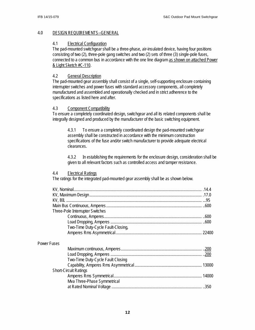
4.4 Electrical Ratings The ratings for the integrated pad-mounted gear assembly shall be as shown below.
KV, Nominal .......................................................................................................................... .14.4 KV, Maximum Design ........................................................................................................... .17.0 KV, BIL ................................................................................................................................. ...95 Main Bus Continuous, Amperes ........................................................................................... ..600 Three-Pole Interrupter Switches Continuous, Amperes ............................................................................................. ..600 Load Dropping, Amperes ....................................................................................... ..600 Two-Time Duty-Cycle Fault-Closing, Amperes Rms Asymmetrical .................................................................................. 22400 Power Fuses Maximum continuous, Amperes ............................................................................. ..200 Load Dropping, Amperes ....................................................................................... ..200 Two-Time Duty-Cycle Fault Closing Capability, Amperes Rms Asymmetrical ................................................................ 13000 Short-Circuit Ratings Amperes Rms Symmetrical .................................................................................... 14000 Mva Three-Phase Symmetrical at Rated Nominal Voltage ...................................................................................... ..350
12
IFB 14/15-079 S&C Outdoor Pad Mount Switchgear
The momentary and two-time duty-cycle fault-closing ratings of switches, momentary rating of bus, and interrupting ratings of fuses shall equal or exceed the short-circuit ratings of the pad-mounted gear.
4.5 Certification of Ratings
4.5.1 Manufacturer of the pad-mounted gear shall be completely and solely responsible for the performance of the basic switch and fuse components as well as the complete integrated assembly as rated. 4.5.2 The manufacturer shall furnish, upon request, certification of ratings of the basic switch and fuse components and/or the integrated pad-mounted gear assembly consisting of the switch and fuse components in combination with the enclosure. This certification on the integrated unit shall include testing the switch gear to the fault close requirements of the specification to assure the bus support system as well as the switch itself is adequate.
4.5.3 The integrated pad-mounted gear assembly shall have a BIL rating established by test on gear on the type and kind to be furnished under the specification. Certified test abstract establishing such rating shall be furnished upon request.
5.0 DESIGN REQUIREMENTS--ELECTRICAL BUS COMPONENTS
5.1 Insulators The interrupter-switch and fuse-mounting insulator shall have the following material characteristics and restrictions:
5.1.1 Operating experience of at least 10 years under similar conditions.
5.1.2 Adequate leakage distance established by test per IEC Publication 507, First Edition, 1975.
5.1.3 Adequate strength for short-circuit stress established by test.
5.1.4 Conformance with applicable ANSI standards. 5.1.5 Homogeneity of the cycloaliphatic epoxy resin throughout each insulator to provide maximum resistance to power arcs. Ablation due to high temperatures from power arcs shall continuously expose more material of the same composition and properties so that no change in mechanical or electrical characteristics takes place because of arc-induced ablation. Furthermore, any surface damage to insulators during installation or maintenance of switchgear shall expose material of the same composition and properties so that insulators with minor surface damage need not be replaced.
5.2 High-Voltage Bus
5.2.1 Bus and interconnections shall consist of aluminum bar of 56 percent IACS conductivity.
5.2.2 The bus supports, bus, and interconnections shall withstand the stresses associated with short-circuit currents up through the maximum rating of the pad-mounted gear, including proper allowance for transient conditions.
13

IFB 14/15-079 S&C Outdoor Pad Mount Switchgear
5.2.3 Bolted aluminum-to-aluminum connections shall be made with a suitable number of ½”-13 non-corrosive steel bolts and with two Belleville spring washers per bolt, one under the bolt head and one under the nut. Bolts shall be tightened to 50 ft-lbs of torque to assure a good electrical connection. 5.2.4 Before installation of the bus, all electrical contact surfaces shall first be prepared by machine abrading to remove the aluminum-oxide film. Immediately after this operation, the electrical contact surfaces shall be coated with a uniform coating of an oxide inhibitor and sealant.
5.3 Ground-Connection Pads
5.3.1 A ground-connection pad shall be provided in each compartment of the pad-mounted gear.
5.3.2 The ground-connection pad shall be constructed of 3/8"-thick steel, which shall be nickel plated and welded to the enclosure, and shall have a short-circuit rating equal to that of the integrated assembly.
5.3.3 Ground-connection pads shall be coated with a uniform coating of an oxide inhibitor and sealant prior to shipment.
6.0 DESIGN REQUIREMENTS--ENCLOSURE CONSTRUCTION INCLUDING OUTDOOR FINISH
6.1 Enclosure
6.1.1 The enclosure shall be unitized monocoque construction (not structural-frame and bolted-sheet) to maximize strength, minimize weight, and inhibit corrosion.
6.1.2 The basic material shall be 11-gauge hot-rolled, pickled and oiled steel sheet.
6.1.3 All structural joints and butt joints shall be welded, and the external seams shall be ground flush and smooth.
6.1.3.1 The gas-metal arc welding process shall be employed to eliminate alkaline residues and to minimize distortion and spatter.
6.1.3.2 Any welds made by other than this method shall be ground and sanded (wire brushed if internal) to remove all scale and alkaline residues formed during welding.
6.1.4 The base shall consist of continuous 90-degree flanges extending completely around all four sides of the enclosure and welded at each corner. Means shall be provided for bolting the entire enclosure to a support pad.
6.1.5 The door openings shall have a 90-degree flanges, facing outward, that shall provide strength and rigidity as well as deep overlapping between doors and door openings to guard against water entry.
14

IFB 14/15-079 S&C Outdoor Pad Mount Switchgear
6.1.6 In consideration of tamper resistance, the enclosure shall conform to or exceed the requirements of NEMA TR1-2.01, except that the test values shall be increased to the following levels:
Inward Axle force--50 pounds Prying Leverage Test--75 foot-pounds Pull Test--150 pounds Probing Wire--14 AWG solid soft-drawn copper
And in addition, the enclosure should meet the Western Underground Committee Guide 2.13 for cabinet security requirements.
6.1.7 A heavy coat of insulating "no-drip" compound shall be applied to the inside surface of the roof to prevent condensation of moisture thereon.
6.1.8 Insulating interphase and end barriers of NEMA GPO3-grade fiberglass-
reinforced polyester shall be provided and mounted for each interrupter switch and each set of power fuses where required to achieve BIL. Additional insulating barriers of the same material shall separate the front compartments from the rear compartments and isolate the tie bus (where furnished).
6.1.9 The enclosure shall be provided with an instruction manual holder.
6.2 Doors
6.2.1 Doors shall be constructed of 11-gauge hot-rolled, pickled and oiled steel sheet.
6.2.2 Doors shall have 90-degree flanges providing a deep overlap with the door opening flanges and shall be formed with folded edges, with the sheared edges folded back into the inside of the door to create a mechanical maze that shall guard against water entry and discourage tampering or insertion of foreign objects.
6.2.3 Doors providing access to high voltage shall have a minimum of two extruded-aluminum hinges with stainless-steel hinge pins, and interlocking extruded aluminum hinge supports for the full length of the door to provide strength, security, and corrosion resistance. Mounting hardware shall be stainless steel or zinc-plated steel, and shall not be externally accessible to guard against tampering. 6.2.4 In consideration of controlled access and tamper resistance, each door (or set of doors) shall be equipped with an automatic three-point latching mechanism. The latching mechanism shall be spring loaded, and shall latch automatically when the doors are closed. All latch points shall latch at the same time to prevent partial latching. A pentahead socket wrench or tool shall be required to actuate the mechanism to unlatch the door and, in the same motion, recharge the spring for the next closing operation. The latching mechanism shall have provision for padlocking that incorporate a means to protect the padlock shackle from tampering, and designed to prevent operation of the latches until the padlock is removed and not allow installation of the padlock until the latching mechanism is closed.
15

IFB 14/15-079 S&C Outdoor Pad Mount Switchgear
6.2.5 Doors providing access to the 600 amp Gang Switch compartments shall have fault indicator "Lexan viewing windows" situated in the upper right corner of right side compartments and the upper left corner of each left side compartment.
6.2.6 Doors providing access to power fuses shall have storage racks in which to store spare units.
6.2.7 Each door shall be provided with a zinc-nickel-steel door holder located above the door opening. The holder shall be hidden from view when the door is closed, and it shall not be possible for the holder to swing inside the enclosure.
6.3 Finish
6.3.1 During fabrication, the areas of structural parts which may later become inaccessible, such as folded edges and overlapping members, shall be given a phosphatizing bath and an iron-oxide zinc-chromate anticorrosion primer to ensure that all surfaces are protected.
6.3.2 Any welds made by other than the gas-shielded short-circuiting transfer welding process shall be ground and sanded (wire brushed if internal) to remove all scale and alkaline residues formed during welding.
6.3.3 Full coverage at joints and blind areas shall be achieved by processing enclosures independently of components such as doors and roofs before assembly into the unitized structures.
6.3.4 All exterior seams shall be filled and sanded smooth for neat appearance.
6.3.5 To remove oils and dirt, to form a chemically and anodically neutral conversion coating to improve the finish-to-metal bond, and to retard underfilm propagation of corrosion, all surfaces shall undergo a thorough automatic pretreatment process before any protective coatings are applied.
6.3.6 After pretreatment, protective coatings shall be applied that shall help resist corrosion and protect the steel enclosure. To establish the capability of the finishing system to resist corrosion and protect the enclosure, representative test specimens coated by the enclosure manufacturer’s finishing system shall satisfactorily pass the following tests:
6.3.6.1 4000 hours of exposure to salt-spray testing per ASTM B 117 with:
(i) Underfilm corrosion not to extend more than 1/32" from the scribe as evaluated per ASTM D 1645, Procedure A, Method 2 (scraping); and
(ii) Loss of adhesion from bare metal not to extend more than 1/8" from the scribe.
6.3.6.2 1000 hours of humidity testing per ASTM D 4585 with no blistering as evaluated per ASTM D 714.
6.3.6.3 500 hours of accelerated weathering testing per ASTM G 53 with no
chalking as evaluated per ASTM D 659, and no more than a 10 percent
16

IFB 14/15-079 S&C Outdoor Pad Mount Switchgear
reduction of paint gloss as evaluated per ASTM D 523.
6.3.6.4 Crosshatch adhesion testing per ASTM D 3359 method B with no loss of paint.
6.3.6.5 160-inch-pound impact adhesion testing per ASTM D 2794 with no paint chipping or cracking.
6.3.6.6 3000 cycles of abrasion testing per ASTM 4060 with no penetration to the substrate.
6.3.6.7 Oil resistance testing consisting of a 72-hour immersion bath in mineral oil with no change of color, no streaking, no blistering, and no loss of hardness
6.3.6.8 3000 cycles of abrasion testing per ASTM 4060 with no penetration to the substrate.
Certified test abstracts substantiating the above capabilities shall be furnished by manufacturer, upon request.
6.3.7 The finishing system shall be applied without sags or runs for a pleasing
appearance. After the finishing system has been properly applied and cured, welds along the enclosure bottom flange shall be coated with an anti-corrosion moisture barrier to give these areas added corrosion resistance.
6.3.8 A PVC gasket shall be applied to the entire underside of the enclosure bottom flange to protect the finish of the on this surface from scratching during handling and installation and additional resistance to corrosion.
6.3.9 After the enclosures are completely assembled and the components (switches, fuses, bus, etc.) are installed, the finish shall be inspected for scuffs and scratches. Blemishes shall be carefully touched up by hand to restore the protective integrity of the finish.
6.3.10 The finish shall be olive green, Munsell 7GY3.29/1.5
6.4 *To guard against corrosion, all hardware (including door fittings, fasteners, etc.), all operating-mechanism parts, and other parts subject to abrasive action from mechanical motion shall be of either nonferrous materials, or galvanized or zinc-nickel plated ferrous materials. Cadmium-plated ferrous parts shall not be used.
6.4 Externally accessible hardware shall not be used for support of high-voltage components or
switch-operating mechanisms within the pad-mounted gear.
17

IFB 14/15-079 S&C Outdoor Pad Mount Switchgear
7.0 DESIGN REQUIREMENTS--BASIC ELECTRICAL COMPONENTS
7.1 Interrupter Switches 7.1.1 Interrupter switches shall have a minimum two-time duty-cycle fault-closing rating equal to or exceeding the short-circuit rating of the integrated pad-mounted gear assembly. These ratings define the ability to close the interrupter switch twice against a three-phase fault with asymmetrical current in at least one phase equal to the rated value, with the switch remaining operable and able to carry and interrupt rated current. Tests substantiating these ratings shall be performed at maximum design voltage with current applied for at least 10 cycles. Certified test abstracts establishing such ratings shall be furnished upon request.
7.1.2 Interrupter switches shall be operated by means of an externally accessible ¾” hex switch-operating hub. The switch-operating hub shall be located within a recessed stainless steel pocket mounted on the side of the enclosure and shall accommodate a ¾” deep-socket wrench or a ¾” shallow-socket wrench with extension. The switch-operating hub pocket shall include a pad lockable stainless steel access cover that shall incorporate a hood to protect the padlock shackle from tampering. Stops shall be provided on the switch-operating hub to prevent overtravel and thereby guard against damage to the interrupter-switch quick-make quick-break mechanism. Labels to indicate switch position shall be provided in the switch-operating hub pocket.
7.1.3 Each interrupter switch shall be provided with a folding switch-operating handle. The switch-operating handle shall be secured to the inside of the switch-operating hub pocket by a brass chain. The folded handle shall be stored behind the closed switch-operating-hub access cover.
7.1.4 Interrupter switches shall utilize a quick-make quick-break mechanism installed by the switch manufacturer. The quick-make quick-break mechanism shall be integrally mounted on the switch frame, and shall swiftly and positively open and close the interrupter switch independent of the switch-operating hub speed. It shall be easily operable using the operating handle by the average lineman without need of additional mechanical leverage.
7.1.5 Each interrupter switch shall be completely assembled and adjusted by the switch manufacturer on a single, rigid mounting frame. The frame shall be of welded steel construction such that the frame intercepts the leakage path which parallels the open gap of the interrupter switch to positively isolate the load circuit when the interrupter switch is in the open position.
7.1.6 For optimal current transfer, interrupter-switch contacts shall be backed up by stainless-steel springs to provide constant high contact pressure.
7.1.7 Interrupter switches shall be provided with a single blade per phase for circuit closing including fault closing, continuous current carrying, and circuit interrupting. Spring-loaded auxiliary blades shall not be permitted. Interrupter-switch blade supports shall be permanently molded in place in a unified rotating insulated shaft constructed of the same cycloaliphatic epoxy resin as the insulators.
18

IFB 14/15-079 S&C Outdoor Pad Mount Switchgear
7.1.8 Circuit interruption shall be accomplished by use of an interrupter through which the blade travels and which is positively and inherently sequenced with the blade position. It shall not be possible for the blade and interrupter to get out of sequence. Circuit interruption shall take place completely within the interrupter, with no external arc or flame. Any exhaust shall be vented in a controlled manner through a deionizing vent.
7.1.9 Interrupter switches shall have a readily visible open gap when in the open position to allow positive verification of switch position.
7.1.10 Polymer Metal-oxide type surge arrestors, rated 10 KV and base mounted shall be provided at each terminal position in each 600 amp switching compartments (Ref. 4.1). Means of connection to the source side terminal shall be provided. The arresters shall be removed and separately packaged for shipment.
7.1.11 Ground studs shall be provided at all switch terminals. Ground studs shall also
be provided on the ground pad in each interrupter-switch compartment. The momentary rating of the ground studs shall equal or exceed the short-circuit ratings of the pad-mounted gear.
7.2 Fuses
7.2.1 Fuses shall be disconnect style, solid material power fuses, and shall utilize a fuse unit and end fitting. The fuse unit shall be readily replaceable and the following shall apply:
7.2.1.1 Fusible elements shall be nonaging and nondamageable so that it is unnecessary to replace unblown companion fuses on suspicion of damage following a fuse operation.
7.2.1.2 Power fuses shall have melting time-current characteristics that are permanently accurate to within a total of 10 percent in terms of current. Time-current characteristics shall be available which permit coordination with protective relays, automatic circuit reclosers, and other fuses.
7.2.1.3 Fusible elements or fuse units, rated 10 amperes or larger, shall be helically coiled to avoid mechanical damage due to stresses from current surges.
7.2.1.4 Fusible elements, that carry continuous current, shall be supported in air to help prevent damage from current surges.
7.2.1.5 Each fusible element or fuse unit shall have a single fusible element to eliminate the possibility of unequal current sharing in parallel current paths.
7.2.1.6 All stationary fuse contacts in combination with the fuse holder shall have a continuous current rating of 400 amperes.
7.2.1.7 Power fuses shall be capable of detecting and interrupting all faults whether large, medium, or small (down to minimum melting current), under all realistic conditions of circuitry, with line-to-line or line-to-ground voltage across
19

IFB 14/15-079 S&C Outdoor Pad Mount Switchgear
the power fuse, and shall be capable of handling the full range of transient recovery voltage severity associated with these faults.
7.2.1.8 All arcing accompanying power fuse operation shall be contained within the fuse and all arc products and gases evolved shall be effectively contained within the exhaust control device during fuse operation.
7.2.1.9 Solid material power fuses shall be equipped with a blown-fuse indicator that shall provide visible evidence of fuse operation while installed in the fuse mounting.
7.2.2 Fuse terminal pads shall be provided with a two-position adapter making it possible to accommodate a variety of cable-terminating devices.
7.2.3 Ground studs shall be provided at all fuse terminals. One ground stud shall also be provided on the ground pad in each fuse compartment. The momentary rating of the ground studs shall equal or exceed the short-circuit ratings of the pad-mounting gear.
8.0 DESIGN REQUIREMENTS--LABELING
8.1 Warning Signs 8.1.1 All external doors shall be provided with "WARNING—KEEP OUT--HAZARDOUS VOLTAGE INSIDE—CAN SHOCK, BURN, OR CAUSE DEATH" signs.
8.1.2 The inside of each door shall be provided with a "DANGER--HAZARDOUS VOLTAGE—FAILURE TO FOLLOW THESE INSTRUCTIONS WILL LIKELY CAUSE SHOCK, BURNS, OR DEATH" sign.
8.1.3 Interrupter switch compartments shall be provided with “DANGER” signs indicating that "SWITCHES MAY BE ENERGIZED BY BACKFEED".
8.1.4 Fuse compartments shall be provided with “DANGER” signs indicating that "FUSES MAY BE ENERGIZED BY BACKFEED".
8.1.5 Any barriers used to guard against access to energized live parts shall be provided with "DANGER-KEEP AWAY- HAZARDOUS VOLTAGE-WILL SHOCK, BURN OR CAUSE DEATH" signs.
8.2 Nameplates, Ratings Labels, and Connection Diagrams
8.2.1 The outside of each door (or set of doors) shall be provided with a nameplate indicating the manufacturer's name, catalog number, date of manufacture, serial number, and model number.
8.2.2 The inside of each door (or set of doors) shall be provided with a ratings label indicating the following: voltage ratings (KV, nominal; KV, maximum design; and KV, BIL); main bus continuous rating (amperes); short-circuit ratings (amperes, rms symmetrical and Mva three-phase symmetrical at rated nominal voltage); the type of fuse and its ratings (amperes, maximum; amperes, interrupting; amperes, line switching-load splitting and load dropping); and interrupter-switch ratings (amperes, continuous; amperes, live switching-load splitting and load dropping; amperes, fault-closing, duty-
20
IFB 14/15-079 S&C Outdoor Pad Mount Switchgear
cycle, two-time-rms symmetrical, rms asymmetrical, and peak; amperes, short-time, rms-momentary, asymmetrical, and one-second symmetrical).
8.2.3 A three-line connection diagram showing interrupter switches, fuses with integral load interrupter, and bus along with the manufacturer's model number shall be provided each door (or set of doors) and on the inside of each switch-operating-hub access cover.
9.0 DESIGN REQUIREMENTS--AUXILIARIES
9.1 SML-20 power fuse mounting provisions, SMU-20 fuse units, and fuse unit end fittings with silencer for original installation, as well as one spare fuse unit and fuse unit end fitting for each fuse position, shall be furnished. Total of six (6) SMU-20 Fuse units and six (6) Fuse unit end fittings, (3 original and 3 spare). 9.1.1 * Unit must be designed to readily field retrofit for the attachment of the S&C
Fault Fiter Electronic fuse units without the requirement for additional unique hardware and/or materials to complete the installation.
9.2 A two bolt, clamp-type connector shall be supplied for each fuse and switch terminal position, twelve (12) total. It shall be a tin-plated bronze body, two galvanized steel bolts with nuts and two Belleville washers. Its conductor range shall be No. 2 solid through 500 MCM stranded copper or aluminum.
9.3 One (1) touch-up kit including primer for the paint color specified to field-dress any scratches from installation. Touch-up paint shall be furnished in 9-oz. Aerosol cans.
10.0 DATA TO BE SUPPLIED WITH EACH BID PROPOSAL
10.1 In addition to the requested information on the proposal pages, each bidder shall include the following with his proposal package:
10.1.1 Typical drawing showing dimensions and outline of the pad-mounted switch.
10.1.2 Bulletins, illustrations, diagrams, etc., necessary to clearly describe the equipment and its components.
10.1.3 Manufacturer warranty including complete explanations of any options to the standard warranty that are available.
10.1.4 A history of successful experience, including the number of years, with pad-mounted switchgear of identical or similar ratings, design and construction. The information submitted shall be representative of the total experience of the manufacturer with the design it purposes to furnish, and include the dates of installation or shipping, the ratings of the equipment and the failures and causes of failures if any have been experienced on this particular design of switchgear.
21

IFB 14/15-079 S&C Outdoor Pad Mount Switchgear
11.0 INFORMATION TO BE SUPPLIED BY SUCCESSFUL BIDDER
11.1 The manufacturer shall prepare and furnish drawings and instruction books descriptive of the equipment for the Purchaser.
11.1.1 Outline drawings showing all dimensions necessary and useful for installation, and the location and identification of major components and accessories.
11.1.2 Complete instructions for installation, operations and maintenance of this switchgear.
11.1.3 Connection diagram and schematic drawings showing all associated wiring and connections.
11.2 Two (2) prints each of drawings, circuit diagram, etc., representing each item of equipment shall be furnished after contract award and prior to construction to City of Danville, Electric Division, Engineering Supervisor, Drawer 3308, Danville, Virginia 24543. One (1) set of these prints will be returned within fifteen (15) days after their submission, with either the approval or the comments of the Engineering Supervisor (not required if no changes in design have been made since the most recent purchase).
11.3 The manufacturer, at least 30 days prior to delivery, shall furnish three (3) complete sets of completed prints and instruction books to the Electric Division at the address above.
11.4 The manufacturer at time of delivery shall supply the following in triplicate:
11.4.1 Certified statement that the standard switchgear complies with these specifications.
12.0 DELIVERY
12.1 All equipment shall be delivered to:
City of Danville, Division of Power & Light Utility Service Building 1040 Monument Street Danville, Virginia 24541
12.2 The manufacturer shall notify the City of shipment approximately forty-eight (48) hours
before arrival.
22
IFB 14/15-079 S&C Outdoor Pad Mount Switchgear
CITY OF DANVILLE, VIRGINIA, DIVISION OF POWER & LIGHT
1.0 SPECIFICATION NO. E 01-4 (PMH-10)
Padmounted Outdoor 14.4 KV Distribution Switchgear
Four 600A Three-Pole Switches (Revised 4/22/03)
2.0 INFORMATION & CONDITIONS
2.1 These specifications are intended to cover the material, design, and construction of a three-phase, four-way, pad-mounted, distribution-switching cabinet to be used outdoors on a 12.47/7.2KV, grounded wye, 60 Hertz system.
2.2 It is the intent of these specifications that the bidder shall furnish his standard outdoor, pad-mounted switchgear complete and operational with standard accessories and any modifications as detailed in these specifications.
2.3 Workmanship, material and design
2.3.1 All workmanship and material shall be of high quality and all material shall be free from defects affecting appearance or serviceability of equipment. 2.3.2 The material and design shall be such as has been proved to be satisfactory for the intended application by past experience and commercial service and by comprehensive laboratory tests.
2.4 Warranty
The successful bidder shall furnish a warranty that the specified equipment will be in accordance with these specifications and with the latest RUS, IEEE, ANSI and NEMA standards. The bidder's standard warranty period shall apply.
3.0 STANDARDS
3.1 The pad-mounted switchgear shall be designed, built, and tested in accordance with the latest manufacturing and testing standards of RUS, IEEE, ANSI, and NEMA. In addition, if not included in the above, the following shall be used in addition:
3.1.1 "RUS Standard for Radio Influence Voltage Limits for 14.4/24.9 KV Insulators and Apparatus" D-11, current edition.
3.1.2 NEMA publication NO. 107, "Method of Measuring Radio Noise", current edition.
3.1.3 Applicable safety and health standards promulgated pursuant to Federal Occupational Safety and Health Act of 1970, as amended, which are in effect 30 days prior to the date of quotation or bid.
3.1.4 Article 710-21(e) in the National Electrical Code, which specifies that the interrupter switches in combination with the power fuses shall safely withstand the effects of closing, carrying, and interrupting all possible currents up to the assigned maximum short-circuit rating.
4.0 DESIGN REQUIREMENTS-GENERAL
4.1 Electrical Configuration The pad-mounted switchgear shall be a three-phase, air-insulated device, having four positions consisting of four (4), three-pole gang switches connected to a common bus in
23

IFB 14/15-079 S&C Outdoor Pad Mount Switchgear
accordance with the one line diagram as shown on attached Power & Light Sketch #C-111.
4.2 General Description The pad-mounted gear assembly shall consist of a single, self-supporting enclosure containing interrupter switches with standard accessory components, all completely manufactured and assembled and operationally checked and in strict adherence to the specifications as listed here and after.
4.3 Component Compatibility To ensure a completely coordinated design, switchgear and all its related components shall be integrally designed and produced by the manufacturer of the basic switching equipment.
4.3.1 To ensure a completely coordinated design the pad-mounted switchgear assembly shall be constructed in accordance with the minimum construction specifications of the fuse and/or switch manufacturer to provide adequate electrical clearances.
4.3.2 In establishing the requirements for the enclosure design, consideration shall be given to all relevant factors such as controlled access and tamper resistance.
4.4 Electrical Ratings The ratings for the integrated pad-mounted gear assembly shall be as shown below.
KV, Nominal .............................................................................................................. .14.4 KV, Maximum Design ............................................................................................... .17.0 KV, BIL ...................................................................................................................... ...95 Main Bus Continuous, Amperes ............................................................................... ..600 Three-Pole Interrupter Switches Continuous, Amperes .................................................................................. ..600 Load Dropping, Amperes ............................................................................. ..600 Two-Time Duty-Cycle Fault-Closing, Amperes Rms Asymmetrical ....................................................................... 22400 Short-Circuit Ratings Amperes Rms Symmetrical ......................................................................... 14000 Mva Three-Phase Symmetrical at Rated Nominal Voltage ............................................................................ ..350
The momentary and two-time duty-cycle fault-closing ratings of switches, momentary rating of bus, and interrupting ratings of fuses shall equal or exceed the short-circuit ratings of the pad-mounted gear.
4.5 Certification of Ratings
4.5.1 Manufacturer of the pad-mounted gear shall be completely and solely responsible for the performance of the basic switch and fuse components as well as the complete integrated assembly as rated. 4.5.2 The manufacturer shall furnish, upon request, certification of ratings of the basic switch components and the integrated pad-mounted gear assembly consisting of the switch components in combination with the enclosure. This certification on the integrated unit shall include testing the switchgear to the fault close requirements of the specification to assure the bus support system as well as the switch itself is adequate.
24

IFB 14/15-079 S&C Outdoor Pad Mount Switchgear
4.5.3 The integrated pad-mounted gear assembly shall have a BIL rating established by test on gear on the type and kind to be furnished under the specification. Certified test abstract establishing such rating shall be furnished by the manufacturer, upon request.
5.0 DESIGN REQUIREMENTS--ELECTRICAL BUS COMPONENTS
5.1 Insulators The interrupter-switch mounting insulator shall have the following material characteristics and restrictions:
5.1.1 Operating experience of at least 10 years under similar conditions.
5.1.2 Adequate leakage distance established by test per IEC Publication 507, First Edition, 1975.
5.1.3 Adequate strength for short-circuit stress established by test.
5.1.4 Conformance with applicable ANSI standards.
5.1.5 Homogeneity of the cycloaliphatic epoxy resin throughout each insulator to provide maximum resistance to power arcs. Ablation due to high temperatures from power arcs shall continuously expose more material of the same composition and properties so that no change in mechanical or electrical characteristics takes place because of arc-induced ablation. Furthermore, any surface damage to insulators during installation or maintenance of switchgear shall expose material of the same composition and properties so that insulators with minor surface damage need not be replaced.
5.2 High-Voltage Bus
5.2.1 Bus and interconnections shall consist of aluminum bar of 56 percent IACS conductivity.
5.2.2 The bus supports, bus, and interconnections shall withstand the stresses associated with short-circuit currents up through the maximum rating of the pad-mounted gear, including proper allowance for transient conditions.
5.2.3 Bolted aluminum-to-aluminum connections shall be made with a suitable number of ½”-13 non-corrosive steel bolts and with two Belleville spring washers per bolt, one under the bolt head and one under the nut. Bolts shall be tightened to 50 foot-pounds of torque to assure a good electrical connection.
5.2.4 Before installation of the bus, all electrical contact surfaces shall first be prepared by machine abrading to remove the aluminum-oxide film. Immediately after this operation, the electrical contact surfaces shall be coated with a uniform coating of an oxide inhibitor and sealant.
5.3 Ground-Connection Pads
5.3.1 A ground-connection pad shall be provided in each compartment of the pad-mounted gear.
5.3.2 The ground-connection pad shall be constructed of 3/8"-thick steel, which shall be nickel plated and welded to the enclosure, and shall have a short-circuit rating equal to that of the integrated assembly.
25

IFB 14/15-079 S&C Outdoor Pad Mount Switchgear
5.3.3 Ground-connection pads shall be coated with a uniform coating of an oxide inhibitor and sealant prior to shipment.
6.0 DESIGN REQUIREMENTS--ENCLOSURE CONSTRUCTION INCLUDING
OUTDOOR FINISH 6.1 Enclosure
6.1.1 *The enclosure shall be unitized monocoque construction (not structural-frame and bolted-sheet) to maximize strength, minimize weight, and inhibit corrosion.
6.1.2 The basic material shall be 11-gauge hot-rolled, pickled and oiled steel sheet.
6.1.3 All structural joints and butt joints shall be welded, and the external seams shall be ground flush and smooth.
6.1.3.1 The gas-metal arc welding process shall be employed to eliminate alkaline residues and to minimize distortion and spatter.
6.1.3.2 Any welds made by other than this method shall be ground and sanded (wire brushed if internal) to remove all scale and alkaline residues formed during welding.
6.1.4 The base shall consist of continuous 90-degree flanges turned in, extending completely around all four sides of the enclosure and welded at each corner. Means shall be provided for bolting the entire enclosure to a support pad.
6.1.5 The door openings shall have a 90-degree flanges, facing outward, that shall provide strength and rigidity as well as deep overlapping between doors and door openings to guard against water entry.
6.1.6 In consideration of tamper resistance, the enclosure shall conform to or exceed the requirements of NEMA TR1-2.01, except that the test values shall be increased to the following levels:
Inward Axle force--50 pounds Prying Leverage Test--75 foot-pounds Pull Test--150 pounds Probing Wire--14 AWG solid soft-drawn copper
And in addition, the enclosure should meet the Western Underground Committee Guide 2.13 for cabinet security requirements.
6.1.7 A heavy coat of insulating "no-drip" compound shall be applied to the inside surface of the roof to prevent condensation of moisture thereon.
6.1.8 Insulating interphase and end barriers of NEMA GPO3-grade fiberglass-reinforced polyester shall be provided and mounted for each interrupter switch where required to achieve BIL ratings. Additional insulating barriers of the same material shall separate the front compartments from the rear compartments and isolate the tie bus (where furnished).
6.1.9 Full Length steel barriers shall separate side by side compartments
6.1.10 Lifting tabs shall be removable. Sockets for the lifting tab attachment bolts shall be blind-tapped. A resilient material shall be placed between contact
26
IFB 14/15-079 S&C Outdoor Pad Mount Switchgear
surfaces of the enclosure and any eyebolt or lifting tab components to prevent the scratching of the enclosure finish. This material shall be non-hygroscopic to prevent moisture from being absorbed and shall be held between the surfaces.
6.1.11 Enclosure shall utilize a vent-roof design so as to not require space heaters and shall utilize a mechanical-maze construction that discourages tampering and the insertion of foreign objects. The roof design will allow ventilation to help keep the interior of the switchgear dry. 6.1.12 Interrupter switches shall be provided with dual-purpose front barriers. These barriers, in their normal hanging positions, shall guard against inadvertent contact with live parts. It shall also be possible to lift these barriers out and insert them into the open gap when the switch is open. A window panel shall be provided to allow viewing of the switch position without removing the barriers. Window panels shall be removable to facilitate phasing and shall be secured to the enclosure with stainless-steel or zinc plated hardware. These barriers shall meet the requirements of Section 381G of the National Electrical Safety Code (ANSI Standard C2).
6.1.13 Each 600 amp Gang Switch compartment shall be provided with
mounting provision for a fault indicator situated in the upper right corner of right side compartments and the upper left corner of each left side compartment. (Ref. 6.2.6)
6.1.14 Cable guides shall be provided at each terminal position in each
switching compartment accommodating conductor sizes #2 through 1000 mcm.
6.1.15 A steel non-compartmented base spacer shall be provided to increase
the elevation of live parts in the pad-mounted gear above the mounting pad by 6, 12, 18 or 24 inches (whichever is specified).
6.1.16 The enclosure shall be provided with an instruction manual holder.
6.2 Doors
6.2.1 Doors shall be constructed of 11-gauge hot-rolled, pickled and oiled steel sheet.
6.2.2 Doors shall have 90-degree flanges providing a deep overlap with the door opening flanges and shall be formed with folded edges, with the sheared edges folded back into the inside of the door to create a mechanical maze that shall guard against water entry and discourage tampering or insertion of foreign objects.
6.2.3 Doors providing access to high voltage shall have a minimum of two extruded-aluminum hinges with stainless-steel hinge pins, and interlocking extruded aluminum hinge supports for the full length of the door to provide strength, security, and corrosion resistance. Mounting hardware shall be stainless steel or zinc-plated steel, and shall not be externally accessible to guard against tampering. 6.2.4 In consideration of controlled access and tamper resistance, each door (or set of doors) shall be equipped with an automatic three-point latching mechanism. The latching mechanism shall be spring loaded, and shall latch
27

IFB 14/15-079 S&C Outdoor Pad Mount Switchgear
automatically when the doors are closed. All latch points shall latch at the same time to prevent partial latching. A pentahead socket wrench or tool shall be required to actuate the mechanism to unlatch the door and, in the same motion, recharge the spring for the next closing operation. The latching mechanism shall have provision for padlocking that incorporate a means to protect the padlock shackle from tampering, and designed to prevent operation of the latches until the padlock is removed and not allow installation of the padlock until the latching mechanism is closed.
6.2.5 Doors providing access to the 600 amp Gang Switch compartments shall have fault indicator "Lexan viewing windows" situated in the upper right corner of right side compartments and the upper left corner of each left side compartment. (Ref. 6.1.13)
6.2.6 Doors providing access to power fuses shall have storage racks in which to store spare units.
6.2.7 Each door shall be provided with a zinc-nickel-steel door holder located above the door opening. The holder shall be hidden from view when the door is closed, and it shall not be possible for the holder to swing inside the enclosure.
6.3 Finish
6.3.1 During fabrication, the areas of structural parts which may later become inaccessible, such as folded edges and overlapping members, shall be given a phosphatizing bath and an iron-oxide zinc-chromate anticorrosion primer to ensure that all surfaces are protected.
6.3.2 Any welds made by other than the gas-shielded short-circuiting transfer welding process shall be ground and sanded (wire brushed if internal) to remove all scale and alkaline residues formed during welding.
6.3.3 Full coverage at joints and blind areas shall be achieved by processing enclosures independently of components such as doors and roofs before assembly into the unitized structures.
6.3.4 All exterior seams shall be filled and sanded smooth for neat appearance.
6.3.5 To remove oils and dirt, to form a chemically and anodically neutral conversion coating to improve the finish-to-metal bond, and to retard underfilm propagation of corrosion, all surfaces shall undergo a thorough automatic pretreatment process before any protective coatings are applied.
6.3.6 After pretreatment, protective coatings shall be applied that shall help resist corrosion and protect the steel enclosure. To establish the capability of the finishing system to resist corrosion and protect the enclosure, representative test specimens coated by the enclosure manufacturer’s finishing system shall satisfactorily pass the following tests:
6.3.6.1 *4000 hours of exposure to salt-spray testing per ASTM B 117 with:
(i) *Underfilm corrosion not to extend more than 1/32" from the scribe as evaluated per ASTM D 1645, Procedure A, Method 2 (scraping); and
28
IFB 14/15-079 S&C Outdoor Pad Mount Switchgear
(ii) Loss of adhesion from bare metal not to extend more than 1/8" from the scribe.
6.3.6.2 1000 hours of humidity testing per ASTM D 4585 with no
blistering as evaluated per ASTM D 714. 6.3.6.3 500 hours of accelerated weathering testing per ASTM G 53 with
no chalking as evaluated per ASTM D 659, and no more than a 10 percent reduction of paint gloss as evaluated per ASTM D 523.
6.3.6.4 Crosshatch adhesion testing per ASTM D 3359 method B with no
loss of paint.
6.3.6.5 160-inch-pound impact adhesion testing per ASTM D 2794 with no paint chipping or cracking.
6.3.6.6 3000 cycles of abrasion testing per ASTM 4060 with no
penetration to the substrate.
6.3.6.7 Oil resistance testing consisting of a 72-hour immersion bath in mineral oil with no change of color, no streaking, no blistering, and no loss of hardness
Certified test abstracts substantiating the above capabilities shall be furnished by manufacturer, upon request.
6.3.7 The finishing system shall be applied without sags or runs for a pleasing
appearance. After the finishing system has been properly applied and cured, welds along the enclosure bottom flange shall be coated with an anti-corrosion moisture barrier to give these areas added corrosion resistance.
6.3.8 A PVC gasket shall be applied to the entire underside of the enclosure bottom flange to protect the finish of the on this surface from scratching during handling and installation and additional resistance to corrosion.
6.3.9 After the enclosures are completely assembled and the components (switches, fuses, bus, etc.) are installed, the finish shall be inspected for scuffs and scratches. Blemishes shall be carefully touched up by hand to restore the protective integrity of the finish.
6.3.10 The finish shall be olive green, Munsell 7GY3.29/1.5.
6.4 To guard against corrosion, all hardware (including door fittings, fasteners, etc.), all operating-mechanism parts, and other parts subject to abrasive action from mechanical motion shall be of either nonferrous materials, or galvanized or zinc-nickel plated ferrous materials. Cadmium-plated ferrous parts shall not be used.
6.5 Externally accessible hardware shall not be used for support of high-voltage components or switch-operating mechanisms within the pad-mounted gear.
29

IFB 14/15-079 S&C Outdoor Pad Mount Switchgear
7.0 DESIGN REQUIREMENTS--BASIC ELECTRICAL COMPONENTS
7.1 Interrupter Switches: 7.1.1 Interrupter switches shall have a minimum two-time duty-cycle fault-closing rating equal to or exceeding the short-circuit rating of the integrated pad-mounted gear assembly. These ratings define the ability to close the interrupter switch twice against a three-phase fault with asymmetrical current in at least one phase equal to the rated value, with the switch remaining operable and able to carry and interrupt rated current. Tests substantiating these ratings shall be performed at maximum design voltage with current applied for at least 10 cycles. Certified test abstracts establishing such ratings shall be furnished by manufacturer upon request.
7.1.2 Interrupter switches shall be operated by means of an externally accessible ¾” hex switch-operating hub. The switch-operating hub shall be located within a recessed stainless steel pocket mounted on the side of the enclosure and shall accommodate a ¾” deep-socket wrench or a ¾” shallow-socket wrench with extension. The switch-operating hub pocket shall include a padlockable stainless steel access cover that shall incorporate a hood to protect the padlock shackle from tampering. Stops shall be provided on the switch-operating hub to prevent overtravel and thereby guard against damage to the interrupter-switch quick-make quick-break mechanism. Labels to indicate switch position shall be provided in the switch-operating hub pocket.
7.1.3 Each interrupter switch shall be provided with a folding switch-operating handle. The switch-operating handle shall be secured to the inside of the switch-operating hub pocket by a brass chain. The folded handle shall be stored behind the closed switch-operating-hub access cover.
7.1.4 Interrupter switches shall utilize a quick-make quick-break mechanism installed by the switch manufacturer. The quick-make quick-break mechanism shall be integrally mounted on the switch frame, and shall swiftly and positively open and close the interrupter switch independent of the switch-operating hub speed. It shall be easily operable using the operating handle by the average lineman without need of additional mechanical leverage.
7.1.5 Each interrupter switch shall be completely assembled and adjusted by the switch manufacturer on a single, rigid mounting frame. The frame shall be of welded steel construction such that the frame intercepts the leakage path which parallels the open gap of the interrupter switch to positively isolate the load circuit when the interrupter switch is in the open position.
7.1.6 For optimal current transfer, interrupter-switch contacts shall be backed up by stainless-steel springs to provide constant high contact pressure.
7.1.7 Interrupter switches shall be provided with a single blade per phase for circuit closing including fault closing, continuous current carrying, and circuit interrupting. Spring-loaded auxiliary blades shall not be permitted. Interrupter-switch blade supports shall be permanently molded in place in a unified rotating insulated shaft constructed of the same cycloaliphatic epoxy resin as the insulators.
7.1.8 Circuit interruption shall be accomplished by use of an interrupter through which the blade travels and which is positively and inherently sequenced with the blade position. It shall not be possible for the blade and interrupter to get out of sequence. Circuit interruption shall take place completely within the interrupter,
30

IFB 14/15-079 S&C Outdoor Pad Mount Switchgear
with no external arc or flame. Any exhaust shall be vented in a controlled manner through a de-ionizing vent.
7.1.9 Interrupter switches shall have a readily visible open gap when in the open position to allow positive verification of switch position.
7.1.10 Metal-oxide type surge arrestors, rated 10 KV and base mounted shall be provided at each terminal position in each 600 amp switching compartments (Ref. 4.1). Means of connection to the source side terminal shall be provided. The arresters shall be removed and separately packaged for shipment.
7.1.11 Ground studs shall be provided at all switch terminals. Ground studs shall also be provided on the ground pad in each interrupter-switch compartment. The momentary rating of the ground studs shall equal or exceed the short-circuit ratings of the pad-mounted gear.
8.0 DESIGN REQUIREMENTS--LABELING
8.1 Warning Signs 8.1.1 All external doors shall be provided with "WARNING—KEEP OUT--HAZARDOUS VOLTAGE INSIDE—CAN SHOCK, BURN, OR CAUSE DEATH" signs.
8.1.2 The inside of each door shall be provided with a "DANGER--HAZARDOUS VOLTAGE—FAILURE TO FOLLOW THESE INSTRUCTIONS WILL LIKELY CAUSE SHOCK, BURNS, OR DEATH" sign.
8.1.3 Interrupter switch compartments shall be provided with “DANGER” signs
indicating that "SWITCHES MAY BE ENERGIZED BY BACKFEED". 8.1.4 8.1.5 Any barriers used to guard against access to energized live parts shall be
provided with "DANGER-KEEP AWAY- HAZARDOUS VOLTAGE-WILL SHOCK, BURN OR CAUSE DEATH" signs.
8.2 Nameplates, Ratings Labels, and Connection Diagrams
8.2.1 The outside of each door (or set of doors) shall be provided with a nameplate indicating the manufacturer's name, catalog number, date of manufacture, serial number, and model number.
8.2.2 The inside of each door (or set of doors) shall be provided with a ratings label indicating the following: voltage ratings (KV, nominal; KV, maximum design; and KV, BIL); main bus continuous rating (amperes); short-circuit ratings (amperes, rms symmetrical and Mva three-phase symmetrical at rated nominal voltage); interrupter-switch ratings (amperes, continuous; amperes, live switching-load splitting and load dropping; amperes, fault-closing, duty-cycle, two-time-rms symmetrical, rms asymmetrical, and peak; amperes, short-time, rms-momentary, asymmetrical, and one-second symmetrical).
8.2.3 A three-line connection diagram showing interrupter switches and bus along with the manufacturer's model number shall be provided each door (or set of doors) and on the inside of each switch-operating-hub access cover.
9.0 DESIGN REQUIREMENTS--AUXILIARIES
9.1 A two bolt, clamp-type connector shall be supplied for each switch terminal position, twelve (12) total. It shall be a tin-plated bronze body, two galvanized steel bolts
31

IFB 14/15-079 S&C Outdoor Pad Mount Switchgear
with nuts and two Belleville washers. Its conductor range shall be No. 2 solid through 500 MCM stranded copper or aluminum.
10.0 DATA TO BE SUPPLIED WITH EACH BID PROPOSAL
10.1 In addition to the requested information on the proposal pages, each bidder shall include the following with his proposal package:
10.1.1 Typical drawing showing dimensions and outline of the pad-mounted switch.
10.1.2 Bulletins, illustrations, diagrams, etc., necessary to clearly describe the equipment and its components.
10.1.3 Manufacturer warranty including complete explanations of any options to the standard warranty that are available.
10.1.4 A history of successful experience, including the number of years, with pad-mounted switchgear of identical or similar ratings, design and construction. The information submitted shall be representative of the total experience of the manufacturer with the design it purposes to furnish, and include the dates of installation or shipping, the ratings of the equipment and the failures and causes of failures if any have been experienced on this particular design of switchgear.
11.0 INFORMATION TO BE SUPPLIED BY SUCCESSFUL BIDDER
11.1 The manufacturer shall prepare and furnish drawings and instruction books descriptive of the equipment for the Purchaser.
11.1.1 Outline drawings showing all dimensions necessary and useful for installation, and the location and identification of major components and accessories.
11.1.2 Complete instructions for installation, operations and maintenance of this switchgear.
11.1.3 Connection diagram and schematic drawings showing all associated wiring and connections.
11.2 Two (2) prints each of drawings, circuit diagram, etc., representing each item of equipment shall be furnished after contract award and prior to construction to City of Danville, Power & Light Division, Engineering Supervisor, 1040 Monument Street, Danville, Virginia 24541. One (1) set of these prints will be returned within fifteen (15) days after their submission, with either the approval or the comments of the Engineering Supervisor (not required if no changes in design have been made since the most recent purchase).
11.3 The manufacturer, at least 30 days prior to delivery, shall furnish three (3) complete sets of completed prints and instruction books to the Power & Light Division at the address above.
11.4 The manufacturer at time of delivery shall supply the following in triplicate:
11.4.1 Certified statement that the standard switchgear complies with these specifications.
32

IFB 14/15-079 S&C Outdoor Pad Mount Switchgear
12.0 DELIVERY
12.1 All equipment shall be delivered to:
City of Danville, Division of Power & Light Utility Service Building 1040 Monument Street Danville, Virginia 24541
33
IFB 14/15-079 S&C Outdoor Pad Mount Switchgear
CITY OF DANVILLE, VIRGINIA, DIVISION OF POWER & LIGHT
1.0 SPECIFICATION NO. E 91-7A (PMH-11)
Padmounted Outdoor 14.4 KV Distribution Switchgear
Three 600A Three-Pole Switches & One 200A Single-Pole Fuses * Revised 12/22/11
2.0 INFORMATION & CONDITIONS
2.1 These specifications are intended to cover the material, design, and construction of a three-phase, four-way, pad-mounted, distribution switching cabinet to be used outdoors on a 12.47/7.2KV, grounded wye, 60 Hertz system.
2.2 It is the intent of these specifications that the bidder shall furnish his standard outdoor, pad-mounted switchgear complete and operational with standard accessories and any modifications as detailed in these specifications.
2.3 Workmanship, material and design
2.3.1 All workmanship and material shall be of high quality and all material shall be free from defects affecting appearance or serviceability of equipment. 2.3.2 The material and design shall be such as has been proved to be satisfactory for the intended application by past experience and commercial service and by comprehensive laboratory tests.
2.4 Warranty
The successful bidder shall furnish a warranty that the specified equipment will be in accordance with these specifications and with the latest RUS, IEEE, ANSI and NEMA standards. The bidder's standard warranty period shall apply. 3.0 STANDARDS
3.1 The pad-mounted switchgear shall be designed, built, and tested in accordance with the latest manufacturing and testing standards of RUS, IEEE, ANSI, and NEMA. In addition, if not included in the above, the following shall be used in addition:
3.1.1 "RUS Standard for Radio Influence Voltage Limits for 14.4/24.9 KV Insulators and Apparatus" D-11, current edition.
3.1.2 NEMA publication NO. 107, "Method of Measuring Radio Noise", current edition.
3.1.3 Applicable safety and health standards promulgated pursuant to Federal Occupational Safety and Health Act of 1970, as amended, which are in effect 30 days prior to the date of quotation or bid.
3.1.4 Article 710-21(e) in the National Electrical Code, which specifies that the interrupter switches in combination with the power fuses shall safely withstand the effects of closing, carrying, and interrupting all possible currents up to the assigned maximum short-circuit rating.
1

IFB 14/15-079 S&C Outdoor Pad Mount Switchgear 4.0 DESIGN REQUIREMENTS-GENERAL
4.1 Electrical Configuration The pad-mounted switchgear shall be a three-phase, air-insulated device, having four positions consisting of three (3), three-pole gang switches and one (1) set of three (3) single-pole fuses, connected to a common bus in accordance with the one line diagram as shown on attached Power & Light Sketch #C-112.
4.2 General Description The pad-mounted gear assembly shall consist of a single, self-supporting enclosure containing interrupter switches and power fuses with standard accessory components, all completely manufactured and assembled and operationally checked and in strict adherence to the specifications as listed here and after.
4.3 Component Compatibility To ensure a completely coordinated design, switchgear and all its related components shall be integrally designed and produced by the manufacturer of the basic switching equipment.
4.3.1 To ensure a completely coordinated design the pad-mounted switchgear assembly shall be constructed in accordance with the minimum construction specifications of the fuse and/or switch manufacturer to provide adequate electrical clearances.
4.3.2 In establishing the requirements for the enclosure design, consideration shall be given to all relevant factors such as controlled access and tamper resistance.
4.4 Electrical Ratings The ratings for the integrated pad-mounted gear assembly shall be as shown below.
KV, Nominal ............................................................................................................. .14.4 KV, Maximum Design ............................................................................................... .17.0 KV, BIL ..................................................................................................................... ...95 Main Bus Continuous, Amperes ............................................................................... ..600 Three-Pole Interrupter Switches Continuous, Amperes .................................................................................. ..600 Load Dropping, Amperes ............................................................................ ..600 Two-Time Duty-Cycle Fault-Closing, Amperes Rms Asymmetrical ....................................................................... 22400 Power Fuses Maximum continuous, Amperes .................................................................. ..200 Load Dropping, Amperes ............................................................................ ..200 Two-Time Duty-Cycle Fault Closing Capability, Amperes Rms Asymmetrical ..................................................... 13000 Short-Circuit Ratings Amperes Rms Symmetrical ........................................................................ 14000 Mva Three-Phase Symmetrical at Rated Nominal Voltage ........................................................................... ..350
The momentary and two-time duty-cycle fault-closing ratings of switches, momentary rating of bus, and interrupting ratings of fuses shall equal or exceed the short-circuit ratings of the pad-mounted gear.
2

IFB 14/15-079 S&C Outdoor Pad Mount Switchgear
4.5 Certification of Ratings
4.5.1 Manufacturer of the pad-mounted gear shall be completely and solely responsible for the performance of the basic switch and fuse components as well as the complete integrated assembly as rated. 4.5.2 The manufacturer shall furnish, upon request, certification of ratings of the basic switch and fuse components and/or the integrated pad-mounted gear assembly consisting of the switch and fuse components in combination with the enclosure. This certification on the integrated unit shall include testing the switch gear to the fault close requirements of the specification to assure the bus support system as well as the switch itself is adequate.
4.5.3 The integrated pad-mounted gear assembly shall have a BIL rating established by test on gear on the type and kind to be furnished under the specification. Certified test abstract establishing such rating shall be furnished upon request.
5.0 DESIGN REQUIREMENTS--ELECTRICAL BUS COMPONENTS
5.1 Insulators The interrupter-switch and fuse-mounting insulators shall have the following material characteristics and restrictions:
5.1.1 Operating experience of at least 10 years under similar conditions.
5.1.2 Adequate leakage distance established by test per IEC Publication 507, First Edition, 1975.
5.1.3 Adequate strength for short-circuit stress established by test.
5.1.4 Conformance with applicable ANSI standards.
5.1.5 Homogeneity of the cycloaliphatic epoxy resin throughout each insulator to provide maximum resistance to power arcs. Ablation due to high temperatures from power arcs shall continuously expose more material of the same composition and properties so that no change in mechanical or electrical characteristics takes place because of arc-induced ablation. Furthermore, any surface damage to insulators during installation or maintenance of switchgear shall expose material of the same composition and properties so that insulators with minor surface damage need not be replaced.
5.2 High-Voltage Bus
5.2.1 Bus and interconnections shall consist of aluminum bar of 56 percent IACS conductivity.
5.2.2 The bus supports, bus, and interconnections shall withstand the stresses associated with short-circuit currents up through the maximum rating of the pad-mounted gear, including proper allowance for transient conditions.
5.2.3 Bolted aluminum-to-aluminum connections shall be made with a suitable number of ½”-13 non-corrosive steel bolts and with two Belleville spring washers per bolt, one under the bolt head and one under the nut. Bolts shall be tightened to the appropriate torque to assure a good electrical connection. 5.2.4 Before installation of the bus, all electrical contact surfaces shall first be prepared by machine abrading to remove the aluminum-oxide film. Immediately after this operation, the electrical contact surfaces shall be coated with a uniform coating of an oxide inhibitor and sealant.
3

IFB 14/15-079 S&C Outdoor Pad Mount Switchgear
5.3 Ground-Connection Pads 5.3.1 A ground-connection pad shall be provided in each compartment of the pad-mounted gear.
5.3.2 The ground-connection pad shall be constructed of 3/8"-thick steel, which shall be nickel plated and welded to the enclosure, and shall have a short-circuit rating equal to that of the integrated assembly.
5.3.3 Ground-connection pads shall be coated with a uniform coating of an oxide inhibitor and sealant prior to shipment.
6.0 DESIGN REQUIREMENTS--ENCLOSURE CONSTRUCTION INCLUDING
OUTDOOR FINISH 6.1 Enclosure
*6.1.1 The enclosure shall be unitized monocoque construction (not structural-frame and bolted-sheet) to maximize strength, minimize weight, and inhibit corrosion.
6.1.2 The basic material shall be 11-gauge hot-rolled, pickled and oiled steel sheet.
6.1.3 All structural joints and butt joints shall be welded, and the external seams shall be ground flush and smooth.
6.1.3.1 The gas metal arc welding process shall be employed to eliminate alkaline residues and to minimize distortion and spatter.
6.1.3.2 Any welds made by other than this method shall be ground and sanded (wire brushed if internal) to remove all scale and alkaline residues formed during welding.
6.1.4 The base shall consist of continuous 90-degree flanges turned inward, extending completely around all four sides of the enclosure and welded at each corner. Means shall be provided for bolting the entire enclosure to a support pad.
6.1.5 The door openings shall have a 90-degree flanges, facing outward, that shall provide strength and rigidity as well as deep overlapping between doors and door openings to guard against water entry.
6.1.6 In consideration of tamper resistance, the enclosure shall conform to or exceed the requirements of NEMA TR1-2.01, except that the test values shall be increased to the following levels:
Inward Axle force--50 pounds Prying Leverage Test--75 foot-pounds Pull Test--150 pounds Probing Wire--14 AWG solid soft-drawn copper
And in addition, the enclosure should meet the Western Underground Committee Guide 2.13 for cabinet security requirements.
6.1.7 A heavy coat of insulating "no-drip" compound shall be applied to the inside surface of the roof to prevent condensation of moisture thereon.
6.1.8 Insulating interphase and end barriers of NEMA GPO3-grade fiberglass-reinforced polyester shall be provided and mounted for each interrupter switch and each set of power fuses where required to achieve BIL rating. Additional insulating barriers of the same material shall separate the front compartments from the rear compartments and isolate the tie bus (where furnished).
4

IFB 14/15-079 S&C Outdoor Pad Mount Switchgear
6.1.9 Full Length steel barriers shall separate side by side compartments.
6.1.10 Lifting tabs shall be removable. Sockets for the lifting tab attachment bolts shall be blind-tapped. A resilient material shall be placed between contact surfaces of the enclosure and any eyebolt or lifting tab components to prevent the scratching of the enclosure finish. This material shall be non-hygroscopic to prevent moisture from being absorbed and shall be held between the surfaces.
6.1.11 Enclosure shall utilize a vent-roof design so as to not require space heaters and shall utilize a mechanical-maze construction that discourages tampering and the insertion of foreign objects. The roof design will allow ventilation to help keep the interior of the switchgear dry.
6.1.12 Interrupter switches shall be provided with dual-purpose front barriers. These barriers, in their normal hanging positions, shall guard against inadvertent contact with live parts. It shall also be possible to lift these barriers out and insert them into the open gap when the switch is open. A window panel shall be provided to allow viewing of the switch position without removing the barriers. These barriers shall meet the requirements of Section 381G of the National Electrical Safety Code (ANSI Standard C2).
6.1.13 Each 600 amp Gang Switch compartment shall be provided with mounting provision for a fault indicator situated in the upper right corner of right side compartments and the upper left corner of each left side compartment. (Ref. 6.2.6)
6.1.14 A fuse-storage compartment shall be provided in one source interrupter compartment. Each fuse-storage compartment shall provide space for storing three spare fuse units with end fittings.
6.1.15 Each fuse position shall be provided with a dual-purpose front barrier. These barriers, in their normal hanging positions, shall guard against inadvertent contact with live parts. It shall also be possible to lift these barriers out and insert them into the open gaps when the fuses are in the disconnect position. These barriers shall meet the requirements of Section 381G of the National Electrical Safety Code (ANSI Standard C2).
6.1.16 Cable guides shall be provided at each terminal position in each switching compartment accommodating conductor sizes No. 2 through 1000 kcmil.
6.1.17 Cable guides shall be provided at each terminal position in the fusing compartment accommodating conductor sizes No. 2 through 4/0. 6.1.17 *A steel non-compartmented base spacer shall be provided to increase the
elevation of live parts in the pad-mounted gear above the mounting pad by 6, 12, 18 or 24 inches (whichever is specified).
6.1.18 The enclosure shall be provided with an instruction manual holder.
6.2 Doors 6.2.1 Doors shall be constructed of 11-gauge hot-rolled, pickled and oiled steel sheet.
6.2.2 Doors shall have 90-degree flanges providing a deep overlap with the door opening flanges and shall be formed with folded edges, with the sheared edges folded back into the inside of the door to create a mechanical maze that shall guard against water entry and discourage tampering or insertion of foreign objects.
6.2.3 Doors providing access to high voltage shall have a minimum of two extruded-aluminum hinges with stainless-steel hinge pins, and interlocking extruded aluminum hinge supports for the full length of the door to provide strength, security, and corrosion resistance. Mounting hardware shall be stainless steel or zinc-plated steel, and shall not
5

IFB 14/15-079 S&C Outdoor Pad Mount Switchgear
be externally accessible to guard against tampering. 6.2.4 In consideration of controlled access and tamper resistance, each door (or set of doors) shall be equipped with an automatic three-point latching mechanism. The latching mechanism shall be spring loaded, and shall latch automatically when the doors are closed. All latch points shall latch at the same time to prevent partial latching. A pentahead socket wrench or tool shall be required to actuate the mechanism to unlatch the door and, in the same motion, recharge the spring for the next closing operation. The latching mechanism shall have provision for padlocking that incorporate a means to protect the padlock shackle from tampering, and designed to prevent operation of the latches until the padlock is removed and not allow installation of the padlock until the latching mechanism is closed.
6.2.5 Doors providing access to the 600 amp Gang Switch compartments shall have fault indicator "Lexan viewing windows" situated in the upper right corner of right side compartments and the upper left corner of each left side compartment. (Ref. 6.1.13)
6.2.6 Doors providing access to power fuses shall have storage racks in which to store spare units.
6.2.7 Each door shall be provided with a zinc-nickel-steel door holder located above the door opening. The holder shall be hidden from view when the door is closed, and it shall not be possible for the holder to swing inside the enclosure.
6.3 Finish
6.3.1 During fabrication, the areas of structural parts which may later become inaccessible, such as folded edges and overlapping members, shall be given a phosphatizing bath and an iron-oxide zinc-chromate anticorrosion primer to ensure that all surfaces are protected.
6.3.2 Any welds made by other than the gas-shielded short-circuiting transfer welding process shall be ground and sanded (wire brushed if internal) to remove all scale and alkaline residues formed during welding.
6.3.3 Full coverage at joints and blind areas shall be achieved by processing enclosures independently of components such as doors and roofs before assembly into the unitized structures.
6.3.4 All exterior seams shall be filled and sanded smooth for neat appearance.
6.3.5 To remove oils and dirt, to form a chemically and anodically neutral conversion coating to improve the finish-to-metal bond, and to retard underfilm propagation of corrosion, all surfaces shall undergo a thorough automatic pretreatment process before any protective coatings are applied.
6.3.6 After pretreatment, protective coatings shall be applied that shall help resist corrosion and protect the steel enclosure. To establish the capability of the finishing system to resist corrosion and protect the enclosure, representative test specimens coated by the enclosure manufacturer’s finishing system shall satisfactorily pass the following tests:
6.3.6.1 4000 hours of exposure to salt-spray testing per ASTM B 117 with:
(i) Underfilm corrosion not to extend more than 1/32" from the scribe as evaluated per ASTM D 1645, Procedure A, Method 2 (scraping); and
(ii) Loss of adhesion from bare metal not to extend more than 1/8" from the scribe.
6
IFB 14/15-079 S&C Outdoor Pad Mount Switchgear
6.3.6.2 1000 hours of humidity testing per ASTM D 4585 with no blistering as evaluated per ASTM D 714.
6.3.6.3 500 hours of accelerated weathering testing per ASTM G 53 with no
chalking as evaluated per ASTM D 659, and no more than a 10 percent reduction of paint gloss as evaluated per ASTM D 523.
6.3.6.4 Crosshatch adhesion testing per ASTM D 3359 method B with no loss of
paint.
6.3.6.5 160-inch-pound impact adhesion testing per ASTM D 2794 with no paint chipping or cracking.
6.3.6.6 3000 cycles of abrasion testing per ASTM 4060 with no penetration to the
substrate.
6.3.6.7 Oil resistance testing consisting of a 72-hour immersion bath in mineral oil with no change of color, no streaking, no blistering, and no loss of hardness
6.3.6.8 3000 cycles of abrasion testing per ASTM 4060 with no penetration to the
substrate.
Certified test abstracts substantiating the above capabilities shall be furnished by manufacturer, upon request.
6.3.7 The finishing system shall be applied without sags or runs for a pleasing
appearance. After the finishing system has been properly applied and cured, welds along the enclosure bottom flange shall be coated with an anti-corrosion moisture barrier to give these areas added corrosion resistance.
6.3.8 A PVC gasket shall be applied to the entire underside of the enclosure bottom flange to protect the finish of the on this surface from scratching during handling and installation and additional resistance to corrosion.
6.3.9 After the enclosures are completely assembled and the components (switches, fuses, bus, etc.) are installed, the finish shall be inspected for scuffs and scratches. Blemishes shall be carefully touched up by hand to restore the protective integrity of the finish.
6.3.10 The finish shall be olive green, Munsell 7GY3.29/1.5.
6.4 To guard against corrosion, all hardware (including door fittings, fasteners, etc.), all operating-mechanism parts, and other parts subject to abrasive action from mechanical motion shall be of either nonferrous materials, or galvanized or zinc-nickel plated ferrous materials. Cadmium-plated ferrous parts shall not be used.
6.5 Externally accessible hardware shall not be used for support of high-voltage components or switch-operating mechanisms within the pad-mounted gear.
7.0 DESIGN REQUIREMENTS--BASIC ELECTRICAL COMPONENTS
7.1 Interrupter Switches 7.1.1 Interrupter switches shall have a minimum two-time duty-cycle fault-closing rating equal to or exceeding the short-circuit rating of the integrated pad-mounted gear assembly. These ratings define the ability to close the interrupter switch twice against a three-phase fault with asymmetrical current in at least one phase equal to the rated value,
7

IFB 14/15-079 S&C Outdoor Pad Mount Switchgear
with the switch remaining operable and able to carry and interrupt rated current. Tests substantiating these ratings shall be performed at maximum design voltage with current applied for at least 10 cycles. Certified test abstracts establishing such ratings shall be furnished upon request.
7.1.2 Interrupter switches shall be operated by means of an externally accessible ¾” hex switch-operating hub. The switch-operating hub shall be located within a recessed stainless steel pocket mounted on the side of the enclosure and shall accommodate a ¾” deep-socket wrench or a ¾” shallow-socket wrench with extension. The switch-operating hub pocket shall include a padlockable stainless steel access cover that shall incorporate a hood to protect the padlock shackle from tampering. Stops shall be provided on the switch-operating hub to prevent overtravel and thereby guard against damage to the interrupter-switch quick-make quick-break mechanism. Labels to indicate switch position shall be provided in the switch-operating hub pocket.
7.1.3 Each interrupter switch shall be provided with a folding switch-operating handle. The switch-operating handle shall be secured to the inside of the switch-operating hub pocket by a brass chain. The folded handle shall be stored behind the closed switch-operating-hub access cover.
7.1.4 Interrupter switches shall utilize a quick-make quick-break mechanism installed by the switch manufacturer. The quick-make quick-break mechanism shall be integrally mounted on the switch frame, and shall swiftly and positively open and close the interrupter switch independent of the switch-operating hub speed. It shall be easily operable using the operating handle by the average lineman without need of additional mechanical leverage.
7.1.5 Each interrupter switch shall be completely assembled and adjusted by the switch manufacturer on a single, rigid mounting frame. The frame shall be of welded steel construction such that the frame intercepts the leakage path which parallels the open gap of the interrupter switch to positively isolate the load circuit when the interrupter switch is in the open position.
7.1.6 For optimal current transfer, interrupter-switch contacts shall be backed up by stainless-steel springs to provide constant high contact pressure.
7.1.7 Interrupter switches shall be provided with a single blade per phase for circuit closing including fault closing, continuous current carrying, and circuit interrupting. Spring-loaded auxiliary blades shall not be permitted. Interrupter-switch blade supports shall be permanently molded in place in a unified rotating insulated shaft constructed of the same cycloaliphatic epoxy resin as the insulators.
7.1.8 Circuit interruption shall be accomplished by use of an interrupter through which the blade travels and which is positively and inherently sequenced with the blade position. It shall not be possible for the blade and interrupter to get out of sequence. Circuit interruption shall take place completely within the interrupter, with no external arc or flame. Any exhaust shall be vented in a controlled manner through a de-ionizing vent.
7.1.9 Interrupter switches shall have a readily visible open gap when in the open position to allow positive verification of switch position.
7.1.10 Metal-oxide type surge arrestors, rated 10 KV and base mounted shall be provided at each terminal position in each 600 amp switching compartments (Ref. 4.1). Means of connection to the source side terminal shall be provided. The arresters shall be removed and separately packaged for shipment.
7.1.11 Ground studs shall be provided at all switch terminals. Ground studs shall also be provided on the ground pad in each interrupter-switch compartment. The momentary
8

IFB 14/15-079 S&C Outdoor Pad Mount Switchgear
rating of the ground studs shall equal or exceed the short-circuit ratings of the pad-mounted gear.
7.2 Fuses
7.2.1 Fuses shall be disconnect style, solid material power fuses, and shall utilize a fuse unit and end fitting. The fuse unit shall be readily replaceable and the following shall apply:
7.2.1.1 Fusible elements shall be nonaging and nondamageable so that it is unnecessary to replace unblown companion fuses on suspicion of damage following a fuse operation.
7.2.1.2 Power fuses shall have melting time-current characteristics that are permanently accurate to within a total of 10 percent in terms of current. Time-current characteristics shall be available which permit coordination with protective relays, automatic circuit reclosers, and other fuses.
7.2.1.3 Fusible elements or fuse units, rated 10 amperes or larger, shall be helically coiled to avoid mechanical damage due to stresses from current surges.
7.2.1.4 Fusible elements, that carry continuous current, shall be supported in air to help prevent damage from current surges.
7.2.1.5 Each fusible element or fuse unit shall have a single fusible element to eliminate the possibility of unequal current sharing in parallel current paths.
7.2.1.6 All stationary fuse contacts in combination with the fuse holder shall have a continuous current rating of 400 amperes.
7.2.1.7 Power fuses shall be capable of detecting and interrupting all faults whether large, medium, or small (down to minimum melting current), under all realistic conditions of circuitry, with line-to-line or line-to-ground voltage across the power fuse, and shall be capable of handling the full range of transient recovery voltage severity associated with these faults.
7.2.1.8 All arcing accompanying power fuse operation shall be contained within the fuse and all arc products and gases evolved shall be effectively contained within the exhaust control device during fuse operation.
7.2.1.9 Solid material power fuses shall be equipped with a blown-fuse indicator that shall provide visible evidence of fuse operation while installed in the fuse mounting.
7.2.2 Fuse terminal pads shall be provided with a two-position adapter making it possible to accommodate a variety of cable-terminating devices.
7.2.3 Ground studs shall be provided at all fuse terminals. One ground stud shall also be provided on the ground pad in each fuse compartment. The momentary rating of the ground studs shall equal or exceed the short-circuit ratings of the pad-mounting gear.
8.0 DESIGN REQUIREMENTS--LABELING
8.1 Warning Signs 8.1.1 All external doors shall be provided with "WARNING—KEEP OUT--HAZARDOUS VOLTAGE INSIDE—CAN SHOCK, BURN, OR CAUSE DEATH" signs.
9

IFB 14/15-079 S&C Outdoor Pad Mount Switchgear
8.1.2 The inside of each door shall be provided with a "DANGER--HAZARDOUS VOLTAGE—FAILURE TO FOLLOW THESE INSTRUCTIONS WILL LIKELY CAUSE SHOCK, BURNS, OR DEATH" sign.
8.1.3 Interrupter switch compartments shall be provided with “DANGER” signs indicating that "SWITCHES MAY BE ENERGIZED BY BACKFEED".
8.1.4 Fuse compartments shall be provided with “DANGER” signs indicating that "FUSES MAY BE ENERGIZED BY BACKFEED".
8.1.5 Any barriers used to guard against access to energized live parts shall be provided with "DANGER-KEEP AWAY- HAZARDOUS VOLTAGE-WILL SHOCK, BURN OR CAUSE DEATH" signs.
8.2 Nameplates, Ratings Labels, and Connection Diagrams
8.2.1 The outside of each door (or set of doors) shall be provided with a nameplate indicating the manufacturer's name, catalog number, date of manufacture, serial number, and model number.
8.2.2 The inside of each door (or set of doors) shall be provided with a ratings label indicating the following: voltage ratings (KV, nominal; KV, maximum design; and KV, BIL); main bus continuous rating (amperes); short-circuit ratings (amperes, rms symmetrical and Mva three-phase symmetrical at rated nominal voltage); the type of fuse and its ratings (amperes, maximum; amperes, interrupting; amperes, line switching-load splitting and load dropping); and interrupter-switch ratings (amperes, continuous; amperes, live switching-load splitting and load dropping; amperes, fault-closing, duty-cycle, two-time-rms symmetrical, rms asymmetrical, and peak; amperes, short-time, rms-momentary, asymmetrical, and one-second symmetrical).
8.2.3 A three-line connection diagram showing interrupter switches, fuses with integral load interrupter, and bus along with the manufacturer's model number shall be provided each door (or set of doors) and on the inside of each switch-operating-hub access cover.
9.0 DESIGN REQUIREMENTS--AUXILIARIES
9.1 SML-20 power fuse mounting provisions, SMU-20 fuse units, and fuse unit end fittings with silencer for original installation, as well as one spare fuse unit and fuse unit end fitting for each fuse position, shall be furnished. Total of six (6) SMU-20 Fuse units and six (6) Fuse unit end brackets, (3 original and 3 spare). 9.1.2 * Unit must be designed to readily field retrofit for the attachment of the S&C Fault
Fiter Electronic fuse units without the requirement for additional unique hardware and/or materials to complete the installation.
9.2 A two bolt, clamp-type connector shall be supplied for each fuse and switch terminal position, twelve (12) total. It shall be a tin-plated bronze body, two galvanized steel bolts with nuts and two Belleville washers. Its conductor range shall be No. 2 solid through 500 MCM stranded copper or aluminum.
9.3 One (1) touch-up kit including primer for the paint color specified to field-dress any scratches from installation. Touch-up paint shall be furnished in 9-oz. Aerosol cans.
10.0 DATA TO BE SUPPLIED WITH EACH BID PROPOSAL
10.1 In addition to the requested information on the proposal pages, each bidder shall include the following with his proposal package:
10.1.1 Typical drawing showing dimensions and outline of the pad-mounted switch.
10

IFB 14/15-079 S&C Outdoor Pad Mount Switchgear
10.1.2 Bulletins, illustrations, diagrams, etc., necessary to clearly describe the equipment and its components.
10.1.3 Manufacturer warranty including complete explanations of any options to the standard warranty that are available.
10.1.4 A history of successful experience, including the number of years, with pad-mounted switchgear of identical or similar ratings, design and construction. The information submitted shall be representative of the total experience of the manufacturer with the design it purposes to furnish, and include the dates of installation or shipping, the ratings of the equipment and the failures and causes of failures if any have been experienced on this particular design of switchgear.
11.0 INFORMATION TO BE SUPPLIED BY SUCCESSFUL BIDDER
11.1 The manufacturer shall prepare and furnish drawings and instruction books descriptive of the equipment for the Purchaser.
11.1.1 Outline drawings showing all dimensions necessary and useful for installation, and the location and identification of major components and accessories.
11.1.2 Complete instructions for installation, operations and maintenance of this switchgear.
11.1.3 Connection diagram and schematic drawings showing all associated wiring and connections.
11.2 Two (2) prints each of drawings, circuit diagram, etc., representing each item of equipment shall be furnished after contract award and prior to construction to City of Danville, Electric Division, Engineering Supervisor, Drawer 3308, Danville, Virginia 24543. One (1) set of these prints will be returned within fifteen (15) days after their submission, with either the approval or the comments of the Engineering Supervisor (not required if no changes in design have been made since the most recent purchase).
11.3 The manufacturer, at least 30 days prior to delivery, shall furnish three (3) complete sets of completed prints and instruction books to the Electric Division at the address above.
11.4 The manufacturer at time of delivery shall supply the following in triplicate:
11.4.1 Certified statement that the standard switchgear complies with these specifications.
12.0 DELIVERY
12.1 All equipment shall be delivered to:
City of Danville, Division of Power & Light Utility Service Building 1040 Monument Street Danville, Virginia 24541
12.2 The manufacturer shall notify the City of shipment approximately forty-eight (48) hours
before arrival.
11

IFB 14/15-079 S&C Outdoor Pad Mount Switchgear DP&L Specification #E91-7A (As revised 12/22/11
PROPOSAL In compliance with Invitation to Bid No. 14/15-079 and subject to all conditions thereof and attached hereto, the undersigned offers and agrees if this bid be accepted to furnish any and all of the items or services (prices to be listed on bid proposal sheets).. ITEM DESCRIPTION 1 Pad-mounted outdoor distribution switchgear with 3 - 600 amp gang switch and 1 - 200 amp fuse
positions, S&C PMH-11, Cat. #55162R4-E2-F2-K7-M2-M3-N6 or approved equal.
S& C Model# Qty. Price Ext. PMH-11, Cat. #55162R4-E2-F2-K7-M2-M3-N6 3 Ea. $__________________
2 SML-20 Fuse Unit End Fittings; S&C #3097 or approved equal.
S& C Model# Qty. Price Ext. #3097 0 Ea. $____________ ______
3 SMU-20, 100 E fuse units S&C #612100 or approved equal.
S& C Model#612100 Qty. Price Ext.
0 Ea. $____________ ______ 4 Touch-up paint kit with primer, S&C #9999-058 (paint) & #9999-061 (primer) or equal
S& C Model# Qty. Price Ext. #9999-058 0 Ea. $____________ ______ #9999-061 0 Ea. $____________ ______ Alternate Model# Qty. Price Ext. ________________________ 0 Ea. $____________ ______ ________________________ 0 Ea. $____________ ______
5 * Accessories: Attachment Brackets & Fittings for Retrofitting Fuse Compartments 3 & 4 for the
installation of S&C Fault Fiter Electronic Power Fuse Units
Fuse Compartment 3 S& C Lower Hinge Assembly# Qty. Price Ext. #SA-41771-1 0 Ea. $____________ ______ #SA-41771-2 0 Ea. $____________ ______
12

IFB 14/15-079 S&C Outdoor Pad Mount Switchgear II. OTHER CONSIDERATIONS
1. Standard warranty period of __ years.
2. Shipping date: With drawing approval ____________. Shipping date: Without drawing approval ____________.
3. Weight of Switchgear Item 1__________lbs. III. EXCEPTIONS TO SPECIFICATIONS 1. _______________________________________________________________________
_______________________________________________________________________ 2. _______________________________________________________________________
_______________________________________________________________________ 3. _______________________________________________________________________
_______________________________________________________________________ Calendar days delivery ARO: With drawing approval ______________ Without drawing approval____________ Company Name:__________________________________________ Address:__________________________________________ City & State:______________________, _______, Zip Code ____________ Signature ____________________________ Title ________________________________ Phone ________________________________
13

IFB 14/15-079 S&C Outdoor Pad Mount Switchgear
City of Danville
IFB 14/15-078 Bid Proposal
A. In compliance with Invitation to Bid No.14/15-078 and subject to all conditions thereof and attached hereto, the undersigned offers and agrees if this bid be accepted to furnish any and all of the items or services for the sum of:
ITEM COMMODITY QTY AMOUNT
1 S&C Model PMH-9, Cat. #55152R4-E3-F2-K7-M2-M3-N6 or approved equal; padmount outdoor distribution switchgear with a 6” base spacer, rated 14.4kv nominal, 95kv BIL, with two (2) 600 amp loadbreak, gang operated switches and two (2) 200 amp continuous/200 amp loadbreak fuse positions for SMU-20 type fuses, complete with mounting provisions and three (3) 9kv metal oxide arrestors for each compartment, and Lexan viewing ports and mounting provision for fault indicator installation in each compartment. Unit to conform to DP&L Spec E91-7.
1 ea. $_________
Offering: Make: Delivery ARO:
2
S&C Model PMH-9, Cat. #55152R4-E3-F2-K7-M2-M3-N6 or approved equal; padmount outdoor distribution switchgear with a 6” base spacer, rated 14.4kv nominal, 95kv BIL, with two (2) 600 amp loadbreak, gang operated switches and two (2) 200 amp continuous/200 amp loadbreak fuse positions for SMU-20 type fuses, complete with mounting provisions and three (3) 9kv metal oxide arrestors for each compartment, and Lexan viewing ports and mounting provision for fault indicator installation in each compartment. Unit to conform to DP&L Spec E91-7
1 ea.
$_________
Offering: Make: Delivery ARO:
3 S&C Model PMH-10, Cat. #55242R4-F2-K1-M2-N6 or approved equal; padmount outdoor distribution switchgear with a 6” base, rated 14.4kv nominal, 95kv BIL, with four (4) 600 amp loadbreak gang operated switches; complete with three (3) 9kv metal oxide arrestors in each compartment, & Lexan viewing ports and mounting provisions for fault indicator installation in each compartment. Unit to conform to DP&L Spec E01-4.
1 ea.
$_________
Offering: Make: Delivery ARO:
PP - 1

IFB 14/15-079 S&C Outdoor Pad Mount Switchgear
4
S&C Model PMH-11, Cat. #55162R4-E2-F2-K7-M2-M3-N6 or approved equal; padmount outdoor distribution switchgear with a 6” base, rated 14.4kv nominal, 95kv BIL, with three (3) 600 amp loadbreak, gang operated switches & one (1) 200 amp continuous/200 amp load break fuse position for SMU-20 type fuses, complete with three (3) 9kv metal oxide arrestors in compartments 1, 2 and 4, with Lexan viewing ports and mounting provisions for fault indicator installation in compartments 1, 2 & 4. Unit to conform to DP&L Spec E91-7A.
3 ea.
$__________
X3= $__________
Offering: Make: Delivery ARO:
5
S&C #3097 or approved equal, fuse unit endfittings for SMU type fuses. Note: Must be compatible with units identified in Items 1 & 3
21 ea.
$__________
X21=
$__________
Offering: Make: Delivery ARO:
6
S&C Cat#712125 or approved equal, 125E Slow Speed SMU-20 fuse units. Note: Must be compatible with units identified in Items 1 & 3.
21 ea.
$__________
X21=
$__________ Offering: Make: Delivery ARO:
7
S&C Cat. #9999-058 & #9999-061 or approved equal; touch-
up paint kit in green color, matching the color of the switchgear cabinet.
5 ea.
$__________
X5= $__________
Offering: Make: Delivery ARO:
B.
The undersigned Bidder acknowledges receipt of the following Addenda, which have been considered in the preparation of this Bid:
No. ____________ Dated _____________
No. ____________ Dated _____________
No. ____________ Dated _____________
PP - 2

IFB 14/15-079 S&C Outdoor Pad Mount Switchgear Company Name Date _________________ Address Zip Code Signature AFFIX COMPANY SEAL (if applicable) Signature (Printed) Title Phone Fax
Commonwealth of Virginia State Corporation Commission Identification Number ____________
PP - 3