
City of Dallas Water Utilities...
46
City of Dallas Water Utilities Department Drafting Standards for Pipeline Projects D.W.U Drafting Standards for Pipeline Projects JANUARY 1998
Transcript of City of Dallas Water Utilities...
City of Dallas Water Utilities Department
Drafting Standards for
Pipeline Projects
D.W.U Drafting Standards for Pipeline Projects JANUARY 1998
Drafting Standards
for Pipeline Projects
First Edition JANUARY, 1988 Effective - MAY, 1988 Revised JANUARY, 1998 Effective - MAY, 1998
For Additional Copies Contact Development Services - Permits Section
320 E. Jefferson Blvd. Room 118 Dallas, Texas 75203
214 - 948 - 4500
City of Dallas Water Utilities Department
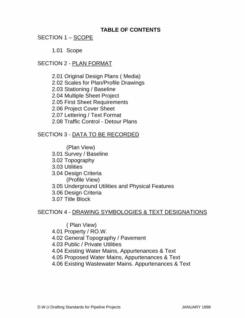
TABLE OF CONTENTS SECTION 1 – SCOPE
1.01 Scope
SECTION 2 - PLAN FORMAT
2.01 Original Design Plans ( Media) 2.02 Scales for Plan/Profile Drawings 2.03 Stationing / Baseline 2.04 Multiple Sheet Project 2.05 First Sheet Requirements 2.06 Project Cover Sheet 2.07 Lettering / Text Format 2.08 Traffic Control - Detour Plans
SECTION 3 - DATA TO BE RECORDED
(Plan View) 3.01 Survey / Baseline 3.02 Topography 3.03 Utilities 3.04 Design Criteria (Profile View) 3.05 Underground Utilities and Physical Features 3.06 Design Criteria 3.07 Title Block
SECTION 4 - DRAWING SYMBOLOGIES & TEXT DESIGNATIONS
( Plan View) 4.01 Property / RO.W. 4.02 General Topography / Pavement 4.03 Public / Private Utilities 4.04 Existing Water Mains, Appurtenances & Text 4.05 Proposed Water Mains, Appurtenances & Text 4.06 Existing Wastewater Mains. Appurtenances & Text
D.W.U Drafting Standards for Pipeline Projects JANUARY 1998
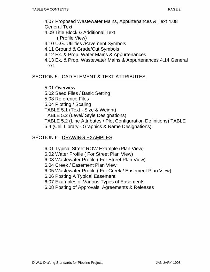
TABLE OF CONTENTS PAGE 2
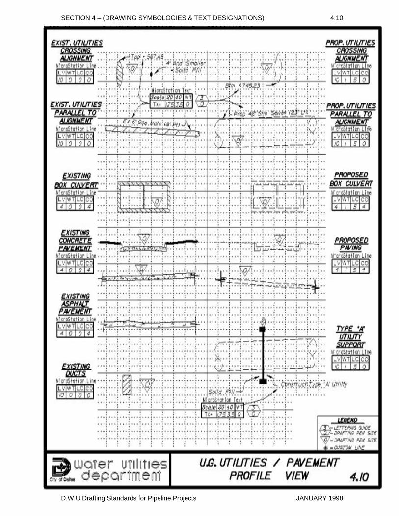
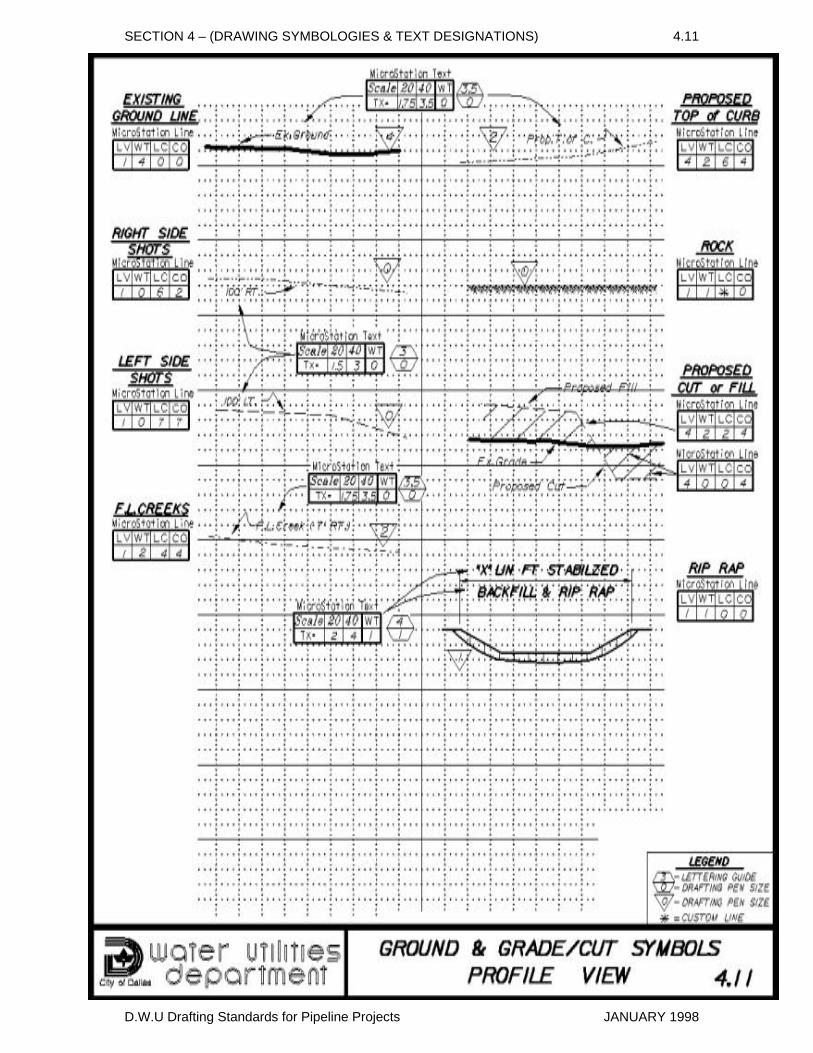
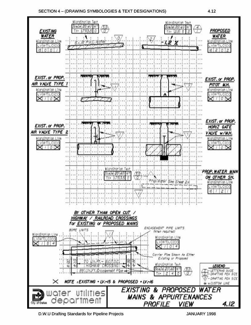
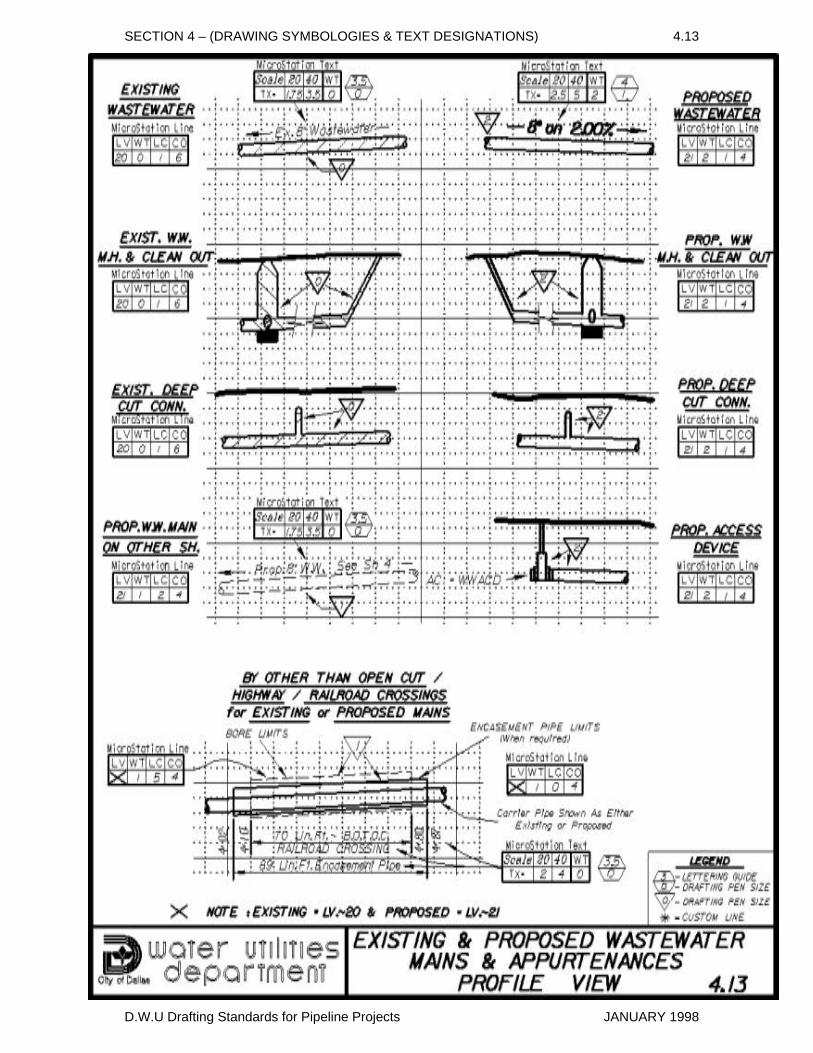
4.07 Proposed Wastewater Mains, Appurtenances & Text 4.08 General Text 4.09 Title Block & Additional Text ( Profile View) 4.10 U.G. Utilities /Pavement Symbols 4.11 Ground & Grade/Cut Symbols 4.12 Ex. & Prop. Water Mains & Appurtenances 4.13 Ex. & Prop. Wastewater Mains & Appurtenances 4.14 General Text
SECTION 5 - CAD ELEMENT & TEXT ATTRIBUTES
5.01 Overview 5.02 Seed Files / Basic Setting 5.03 Reference Files 5.04 Plotting / Scaling TABLE 5.1 (Text - Size & Weight) TABLE 5.2 (Level/ Style Designations) TABLE 5.2 (Line Attributes / Plot Configuration Definitions) TABLE 5.4 (Cell Library - Graphics & Name Designations)
SECTION 6 - DRAWING EXAMPLES
6.01 Typical Street ROW Example (Plan View) 6.02 Water Profile ( For Street Plan View) 6.03 Wastewater Profile ( For Street Plan View) 6.04 Creek / Easement Plan View 6.05 Wastewater Profile ( For Creek / Easement Plan View) 6.06 Posting A Typical Easement 6.07 Examples of Various Types of Easements 6.08 Posting of Approvals, Agreements & Releases
D.W.U Drafting Standards for Pipeline Projects JANUARY 1998
SECTION 1
(SCOPE)
The drafting standards in this manual are to apply to the preparation of design plans for construction of water distribution mains and wastewater mains which will be under the jurisdiction of the Water Utilities Department. These design plans will become a permanent document/record of the distribution or collection system; therefore these standards must be adhered to. This manual contains the requirements for establishing: plan format, drafting symbology, arrangement of specific design notes, and general design notes. These standards are compatible with drafting table techniques as well as the Microstation / Intergraph computer aided (CAD) technology.
D.W.U Drafting Standards for Pipeline Projects JANUARY 1998
SECTION 2
(PLAN FORMAT)
2.01 Original Design Plans (media)
Original plans are to be plotted in ink on 24"x36", 4 mil, double matte, mylar sheets. Plans are to have standard D.W.U. border, title block, and profile grid ( CAD reference files are available). The orientation of the plan view should allow the placement of the design lengthwise along the plan sheet while orientating north towards the top or right side of the view.
Three sheet configurations are available for developing design plans: A) Plans with Profile sheet: The plan / profile sheet is recommended for general use as it allows the placement of the design plan view and profile view on the same sheet. B) Full Plan Sheet: The full plan sheet may be used when a plan / profile sheet does not provide sufficient plan space, when a design can be developed independently of a profile or when developing structural details. When a design requires a full plan sheet and also needs a profile, then a full profile sheet must be included with the design. The design must be thoroughly referenced to file, sheet, and line designation between the plan sheet and the profile sheet. C) Full Profile Sheet: Full profile sheets are used to provide supplemental profile space.
2.02 Scales for Plan/Profile Drawings The following scales are acceptable for developing / plotting design plans. Exceptions to these scales require approval by a Project Designer. (Note: CAD drawings are to be developed at a I to I ratio and then plotted to scale.)
A) Plan View / Horizontal Scale: 1 "=40' This scale is recommended & preferred for general use since it allows the efficient use of plan space while providing sufficient plan detail.
D.W.U Drafting Standards for Pipeline Projects JANUARY 1998

SECTION 2 – (PLAN FORMAT) PAGE 2
1"=20' This scale provides sufficient plan detail for typically congested projects similar to replacement mains that are constructed in alleys, easement, or street R.O.W.s which have an extensive number of underground facilities.
B) Profile View / Vertical Scale: 1"=6' All profiles are to be drawn on the vertical scale of 1 "=6' with major horizontal lines at five (5) foot intervals and to the same horizontal scale as the plan view.
C) Special Details: Special details, such as structures, may require the use of a scale which can provide greater detail than those available on the standard civil engineer scale. For these instances, the use of an appropriate architectural scale which provides greater detail is acceptable.
2.03 Stationing / BaselineAll water and wastewater pipeline projects shall be developed with a continuous one hundred foot stationing format. This station format provides the means of referencing pertinent points of construction and proposed appurtenances along with providing a reference between the plan and profile views. Typically, projects will begin with a zero station point (0+00) established by a field survey and then proceed to the project ending point. When a field survey is not available, a in-office baseline format must be developed. The beginning station (0+00) for proposed wastewater mains shall be at the down stream connection point (M.H.), then proceed up stream. When not dictated by a down stream connection point, stationing should begin from west to east, or south to north (the Designer should specify this with their survey request). The west to east and south to north stationing configuration provides left to right reading of plans (with north directed to the top or to the right).
D.W.U Drafting Standards for Pipeline Projects JANUARY 1998
SECTION 2 – (PLAN FORMAT) PAGE 3
2.04 Multiple Sheet ProjectsWhen a design spans more than one plan sheet, a design match mark must be established to reference the continuation of the design from one sheet to another. The following guidelines should be followed when establishing the location of match marks:
A) Match Marks are to be placed at full or half station points (e.g. 10+00 or 10+50). B) Match Marks are to be perpendicular to the design alignment at the station referenced as the match mark point. C) When at all possible, place match marks outside of street intersections, highway crossings, railroad crossings and areas of proposed construction by other than open cut. D) Place match marks to maximize the use of the available plan and profile space while considering any space requirements of location maps, general notes, construction details, etc. E) Analyze the profile section at the proposed match mark and insure that the location of the match mark will not create any confusion in the profile view.
When an extensive vertical drop occurs in the profile view, a profile vertical shift match mark may be required. This type of match mark allows the vertical shifting of the design so it can be fitted into the profile view. The profile vertical shift match mark should be placed at full or half station points (e.g. 7+00 or 7+50) and the elevations clearly indicated in each shift area.
2.05 First Sheet RequirementsIn addition to any designs, the first sheet is to include a project location map, and a listing of pertinent general notes. For projects having six or more plan sheets, the location maps and general notes may be incorporated as part of a project cover sheet in lieu of placement on the first design sheet.
D.W.U Drafting Standards for Pipeline Projects JANUARY 1998
SECTION 2 – (PLAN FORMAT) PAGE 4
A) Location maps, not placed on cover sheets, should be positioned at the upper right hand comer on the first sheet plan view and oriented with north pointing to the top of the sheet. It shall be of sufficient detail and size (normally 3 to 4 inches square) to convey the project location in reference to the local thoroughfares. The project is to be identified and its limits indicated with leader lines. B) General Notes that apply to the construction of an entire project should be listed on the cover sheet or on the first sheet for projects without a cover sheet. General notes that apply to only one sheet, or multiple sheets for only one portion of the overall project shall appear on the first sheet of that portion for which the notes apply.
2.06 Project Cover SheetSingle facility projects having six or more plan view sheets or multiple location projects are to have a project cover sheet. The cover sheet is to incorporate project name, contract number, sheet key map, file number index, project location map, general notes and may include construction phasing.
A) Single facility type projects (i.e. major transmission/interceptor pipelines) shall have a sheet key map incorporated into the cover sheet. The map is to show the overall layout of the project and indicate the limits of each design sheet. B) Multiple location projects (i.e. replacement/rehabilitating facilities at various locations) shall have a file number to street/location index and detailed location maps for each area of the project.
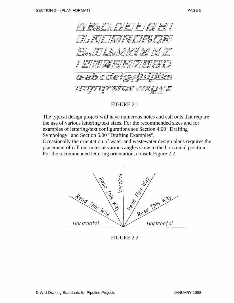
2.07 Lettering / Text FormatThe standard lettering style for design plans is single stroke, upper and lower case, inclined Gothic letters (Intergraph / Microstation Text Font 23). This style of lettering has been the standard for the civil engineering field and produces a neat, legible text that can be accomplished quickly by free hand lettering (see Figure 2.1).
D.W.U Drafting Standards for Pipeline Projects JANUARY 1998
SECTION 2 – (PLAN FORMAT) PAGE 5
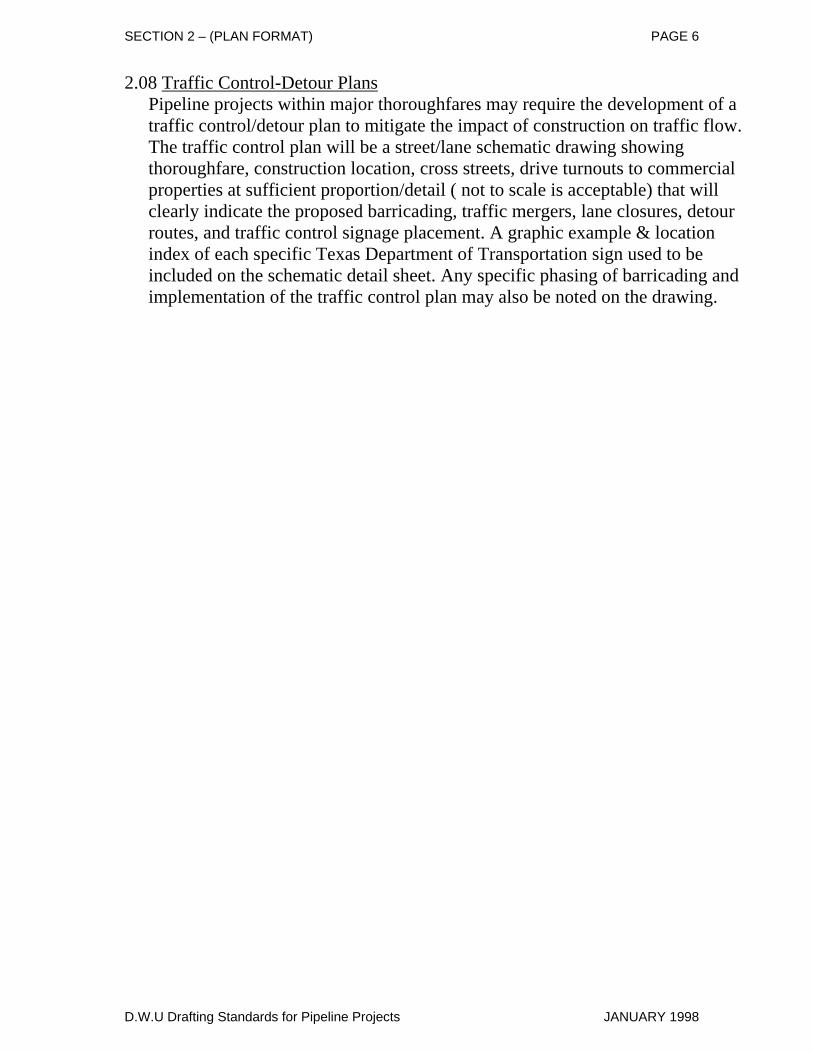
FIGURE 2.1 The typical design project will have numerous notes and call outs that require the use of various lettering/text sizes. For the recommended sizes and for examples of lettering/text configurations see Section 4.00 "Drafting Symbology" and Section 5.00 "Drafting Examples". Occasionally the orientation of water and wastewater design plans requires the placement of call out notes at various angles skew to the horizontal position. For the recommended lettering orientation, consult Figure 2.2.
FIGURE 2.2
D.W.U Drafting Standards for Pipeline Projects JANUARY 1998
SECTION 2 – (PLAN FORMAT) PAGE 6
2.08 Traffic Control-Detour PlansPipeline projects within major thoroughfares may require the development of a traffic control/detour plan to mitigate the impact of construction on traffic flow. The traffic control plan will be a street/lane schematic drawing showing thoroughfare, construction location, cross streets, drive turnouts to commercial properties at sufficient proportion/detail ( not to scale is acceptable) that will clearly indicate the proposed barricading, traffic mergers, lane closures, detour routes, and traffic control signage placement. A graphic example & location index of each specific Texas Department of Transportation sign used to be included on the schematic detail sheet. Any specific phasing of barricading and implementation of the traffic control plan may also be noted on the drawing.
D.W.U Drafting Standards for Pipeline Projects JANUARY 1998
SECTION 3
(DATA TO BE RECORDED) 3.01 Survey Information (PLAN VIEW)
Survey / Baselines are to include the following information: A) Centerline stations, deflection angles, and curve data. B) Ties to all topographical and physical features located by survey. C) Stations and distances to iron pins and boundary monuments. D) Bearings and distances for the boundaries of all properties through which easements are to be obtained. E) Control Number (When Survey Performed by D.W.U.).
3.02 Topography (PLAN VIEW) The majority of the existing topographical information will be obtained from a survey. Additional topographical information may be obtained from existing or proposed paving plans, storm drainage plans, tax maps and investigative field trips. The following existing and/or proposed features should be shown:
A) Roadways (material type, thickness, widths and bases). B) Driveways (material type, thickness, widths and bases). C) High and Low Banks for Creeks. D) All trees/special landscaping within R.O.W. or within 25 feet of survey line. E) Fences and retaining walls within R.O.W. or within 25 feet of survey line. F) All dedicated R.O.W.'s (streets, alleys, railroads, highways, utilities, etc.) with names and owners shown. G) Lot and Block numbers. H) Corporation lines with involved cities listed. I) Any buildings with their address which might be impacted by main construction.
D.W.U Drafting Standards for Pipeline Projects JANUARY 1998
SECTION 3 – (DATA TO BE RECORDED) PAGE 2
3.03 Utilities (PLAN VIEW) Existing and proposed utility information should initially be obtained from the utility records supplied by each utility and then its location confirmed by survey or investigative field trip. The following existing and/or proposed utility information should be shown on design plans:
A) Type and size of utility (i.e. PIP & Anchors etc.). B) Location in reference to R.O.W. C) Type of pipe/conduits and appurtenances. D) Direction of flow for storm drainage and wastewater mains. E) Utility caution notes with current representative contacts. F) Design references and As-Built References.
3.04 Design Criteria (PLAN VIEW) The designer is to provide the following design information in the plan view:
A) The design alignment with reference to its location from survey, R.O.W., physical features, other utilities, etc. B) Specific design notes, stationed and organized in a sequential arrangement around the items described for construction. C) All design station equations, P.I. points, and all curve data (length, radius, tangent, delta angle, etc). D) For areas of construction "By Other Than Open Cut" indicate station limits of construction, type of encasement pipe (when applicable) and any special conditions. E) The specific size and type of material of proposed main when applicable for the plan view. F) Indicate the location and limits of any existing facility being replaced, removed, killed or abandoned. G) The general notes that are applicable to the specific conditions regarding the design.
D.W.U Drafting Standards for Pipeline Projects JANUARY 1998
SECTION 3 – (DATA TO BE RECORDED) PAGE 3
3.05 Underground Utilities and Physical Features (PROFILE VIEW) Utility information can be obtained from several sources (Survey, Utility Maps, Previous Designs, Field Investigations, etc.) and then consolidated into the design profile view:
A) Existing and proposed ground lines. B) Proposed top of curb (when available). C) Station and elevations of existing and proposed utilities that cross the alignment of the proposed D.W.U. facility. D) 100 ft. stationing along bottom of profile. E) 100 ft. left and right ground lines (for wastewater collection mains in unserved areas). F) Show short sections of existing or proposed utilities that run parallel to the proposed D.W.U. facilities.
3.06 Design Criteria (PROFILE VIEW) The designer is to provide the following design information in the profile view:
A) Place the station and description above the main for all proposed appurtenances, and fittings on the main alignment. B) Place flow line elevations below the main at: changes in elevation, grade breaks, beginning and ending of main and at significant main line appurtenances (excluding valves without M.H.'s). C) Show station equations and designate the amount of gap or overlap. D) List stations and elevations at P.V.C., P.V.I., P.V.T., and length of vertical curves. E) Show percent grades along the vertical alignment of all proposed D.W.U. mains. F) For areas of construction "By Other Than Open Cut" indicate station limits of construction, type of encasement pipe (when applicable) and any special conditions.
D.W.U Drafting Standards for Pipeline Projects JANUARY 1998
SECTION 3 – (DATA TO BE RECORDED) PAGE 4
G) List the linear feet of pipe, pipe size, acceptable pipe materials (including class and/or material specifications) and pipe embedment classification. H) Show a minimum of two benchmarks per project and one per sheet. One benchmark should describe an elevation at the beginning of the project and one benchmark should describe an elevation at the ending of project.
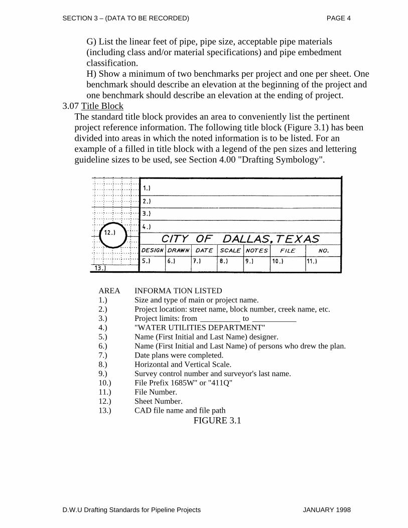
3.07 Title BlockThe standard title block provides an area to conveniently list the pertinent project reference information. The following title block (Figure 3.1) has been divided into areas in which the noted information is to be listed. For an example of a filled in title block with a legend of the pen sizes and lettering guideline sizes to be used, see Section 4.00 "Drafting Symbology".
AREA INFORMA TION LISTED 1.) Size and type of main or project name. 2.) Project location: street name, block number, creek name, etc. 3.) Project limits: from __________ to ___________ 4.) "WATER UTILITIES DEPARTMENT" 5.) Name (First Initial and Last Name) designer. 6.) Name (First Initial and Last Name) of persons who drew the plan. 7.) Date plans were completed. 8.) Horizontal and Vertical Scale. 9.) Survey control number and surveyor's last name. 10.) File Prefix 1685W" or "411Q" 11.) File Number. 12.) Sheet Number. 13.) CAD file name and file path
FIGURE 3.1
D.W.U Drafting Standards for Pipeline Projects JANUARY 1998
SECTION 4
(Drawing Symbologies & Text Designations)
LEGEND for MicroStation Key-In AC = Active Cell CO = Color LC = Line Code (Style) LV = Level Designation TX = Text Size WT = Weight
D.W.U Drafting Standards for Pipeline Projects JANUARY 1998
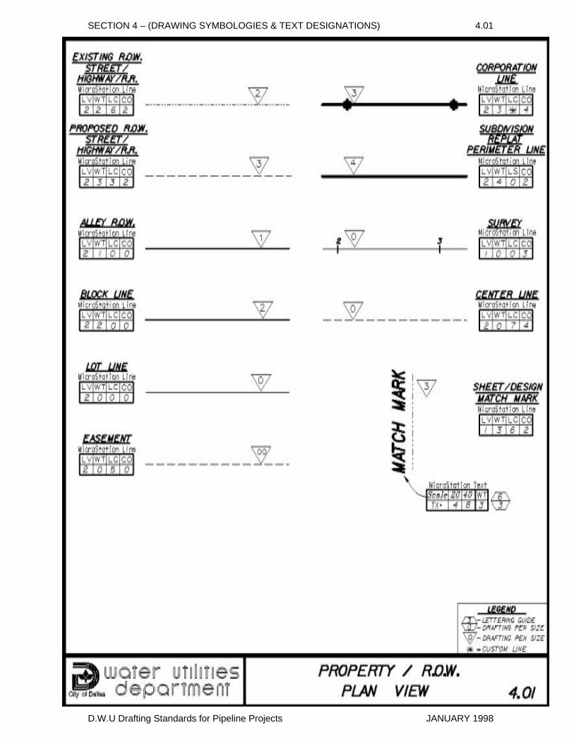
SECTION 4 – (DRAWING SYMBOLOGIES & TEXT DESIGNATIONS) 4.01
D.W.U Drafting Standards for Pipeline Projects JANUARY 1998
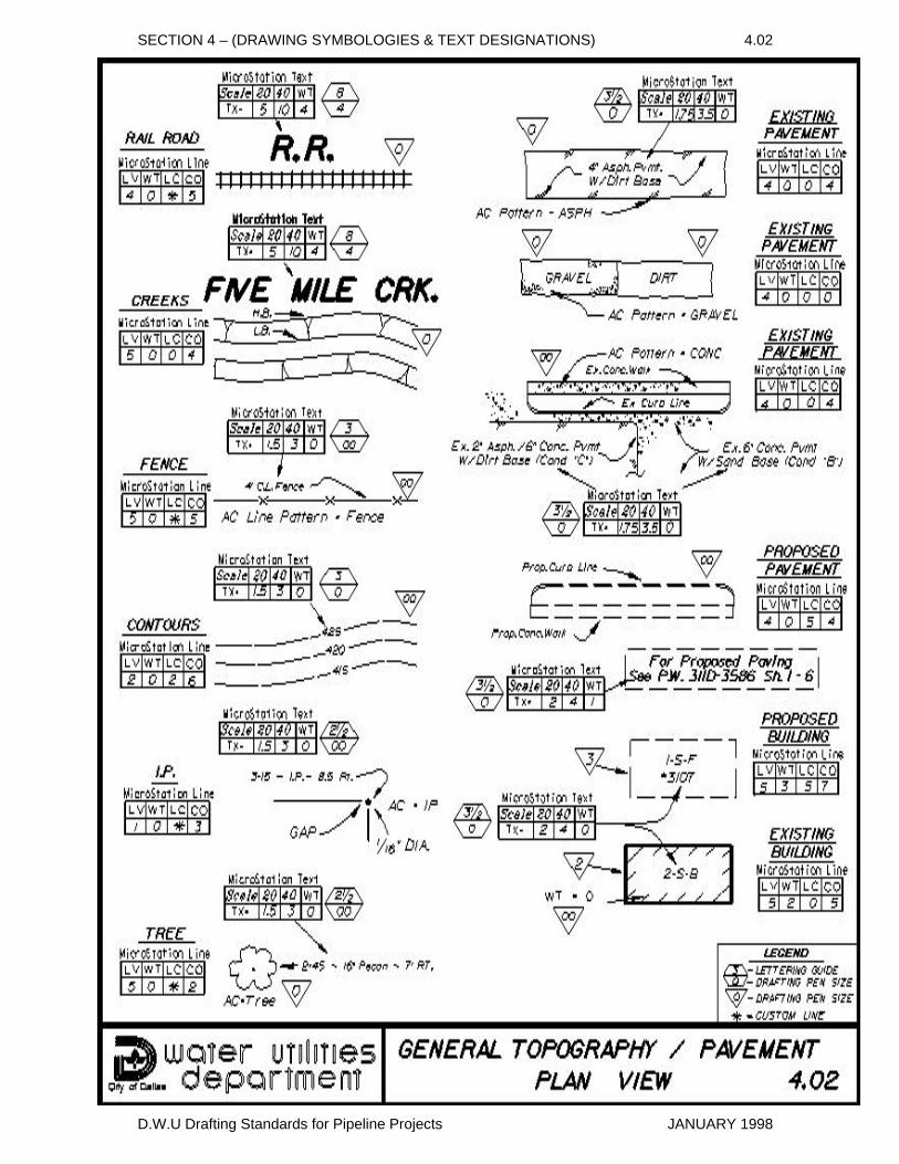
SECTION 4 – (DRAWING SYMBOLOGIES & TEXT DESIGNATIONS) 4.02
D.W.U Drafting Standards for Pipeline Projects JANUARY 1998
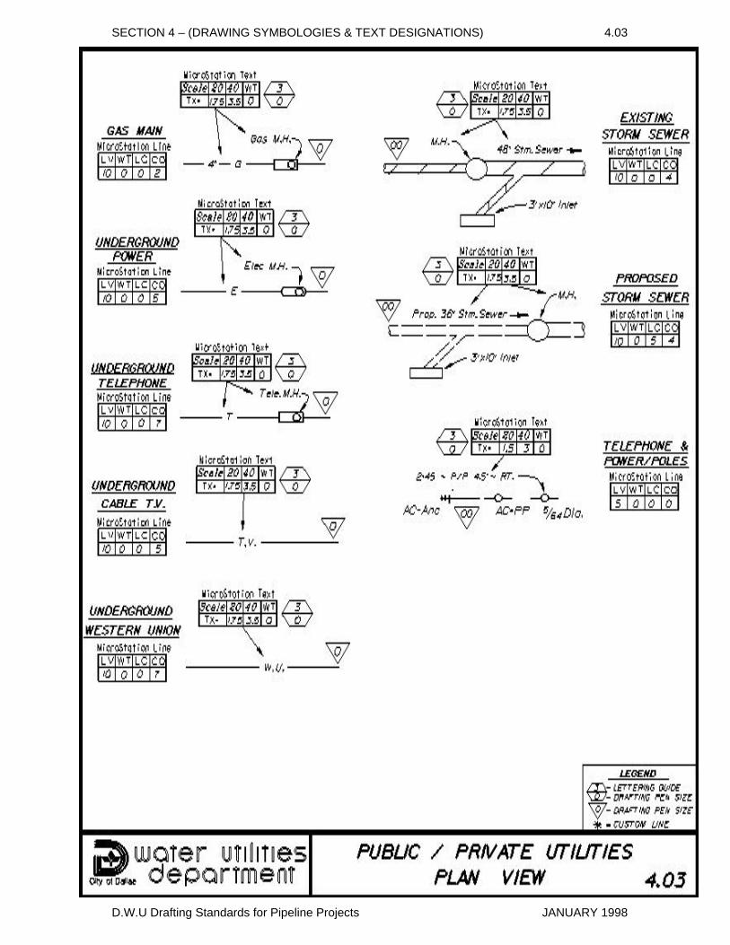
SECTION 4 – (DRAWING SYMBOLOGIES & TEXT DESIGNATIONS) 4.03
D.W.U Drafting Standards for Pipeline Projects JANUARY 1998
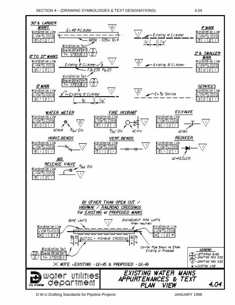
SECTION 4 – (DRAWING SYMBOLOGIES & TEXT DESIGNATIONS) 4.04
D.W.U Drafting Standards for Pipeline Projects JANUARY 1998
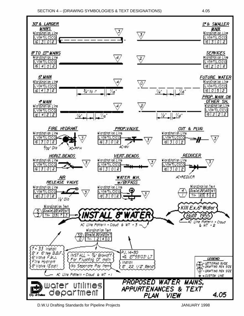
SECTION 4 – (DRAWING SYMBOLOGIES & TEXT DESIGNATIONS) 4.05
D.W.U Drafting Standards for Pipeline Projects JANUARY 1998
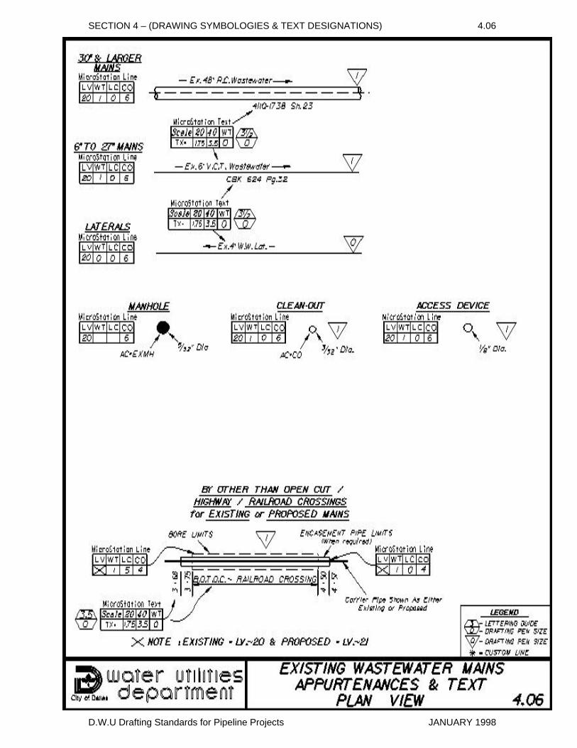
SECTION 4 – (DRAWING SYMBOLOGIES & TEXT DESIGNATIONS) 4.06
D.W.U Drafting Standards for Pipeline Projects JANUARY 1998
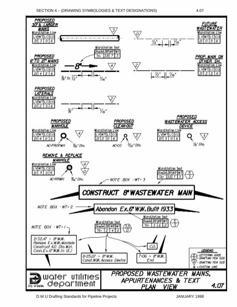
SECTION 4 – (DRAWING SYMBOLOGIES & TEXT DESIGNATIONS) 4.07
D.W.U Drafting Standards for Pipeline Projects JANUARY 1998
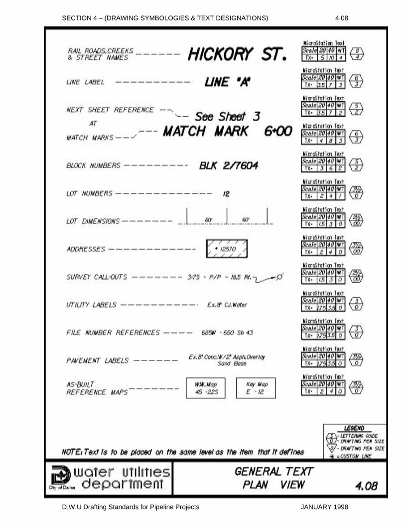
SECTION 4 – (DRAWING SYMBOLOGIES & TEXT DESIGNATIONS) 4.08
D.W.U Drafting Standards for Pipeline Projects JANUARY 1998
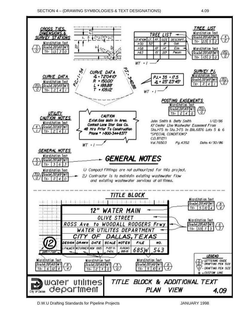
SECTION 4 – (DRAWING SYMBOLOGIES & TEXT DESIGNATIONS) 4.09
D.W.U Drafting Standards for Pipeline Projects JANUARY 1998
SECTION 4 – (DRAWING SYMBOLOGIES & TEXT DESIGNATIONS) 4.10
D.W.U Drafting Standards for Pipeline Projects JANUARY 1998
SECTION 4 – (DRAWING SYMBOLOGIES & TEXT DESIGNATIONS) 4.11
D.W.U Drafting Standards for Pipeline Projects JANUARY 1998
SECTION 4 – (DRAWING SYMBOLOGIES & TEXT DESIGNATIONS) 4.12 SECTION 4 – (DRAWING SYMBOLOGIES & TEXT DESIGNATIONS) 4.12
D.W.U Drafting Standards for Pipeline Projects JANUARY 1998
D.W.U Drafting Standards for Pipeline Projects JANUARY 1998
SECTION 4 – (DRAWING SYMBOLOGIES & TEXT DESIGNATIONS) 4.13
D.W.U Drafting Standards for Pipeline Projects JANUARY 1998
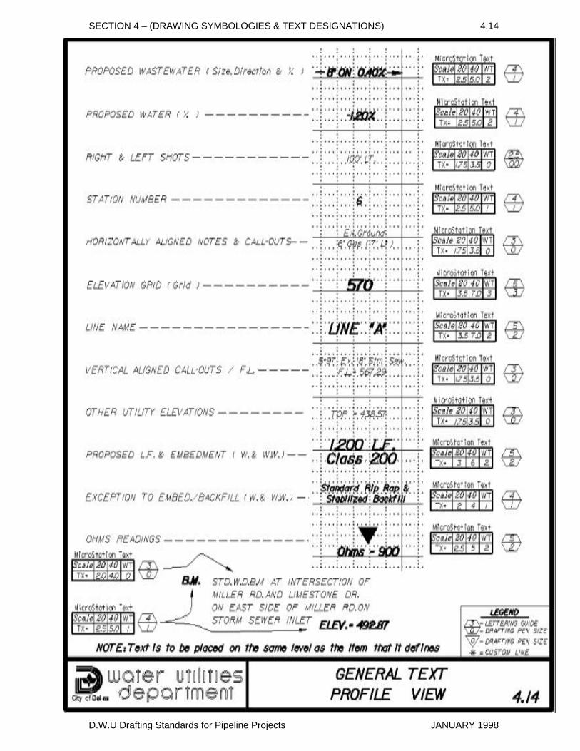
SECTION 4 – (DRAWING SYMBOLOGIES & TEXT DESIGNATIONS) 4.14
D.W.U Drafting Standards for Pipeline Projects JANUARY 1998
SECTION 5 (CAD ELEMENT & TEXT ATTRIBUTES)
5.01 Overview
The CAD elements and text attributes defined in this manual apply to the Microstation/Intergraph software format. All drawings created by CAD processes are to be similar in appearance to drawings that are developed by hand using D.W.U. drawing standards. The tables contained in this section are compilations of CAD parameters to be used. (see also SECTION 4 )
5.02 Seed Files / Basic SettingsThe Microstation CAD format allows the creation of drawings with basic settings (predefined seed file & project interface ), that define file appearance along with defining active drawing parameters. The following settings are germane to D.W.U.'s file setup and were developed from MicroStation's default project interface and two dimensional seed file.
A) Working Units: 1 m.u. ( ft or '), 12 s.u. ( in or " ), 1.000 p.u. ( unit per s.u. ) B) Cell Library : DWU.CELL, is a library of common D.W.U. cells (symbols) developed by Design Services for items used in creating drawings. C) Color Table: COLOR.TBL a standard table provided by Microstation D) Element Class: PRIMARY for all elements E) Dimension Format & Units: Format: MECHANICAL Primary Unit: ENGLISH (ft. or ' & in. or " ) Angle Format: DEGREES Angle Display: Deg.(°) Min.(,) Sec.(") i.e. 45°25'30" Minimum Accuracy: 0.12 or 2-PLACE
D.W.U Drafting Standards for Pipeline Projects JANUARY 1998
SECTION 5 – (CAD ELEMENT & TEXT ATTRIBUTES) PAGE 2
5.03 Reference Files
During the development of the drawing/design, the use of reference files is an acceptable and sometimes a very efficient procedure for managing the project. However, when the project is completed (prior to archiving or delivering CAD files to D.W.U. Mapping & Capital Services for permanent storage), the file is to be copied into a stand-alone format with all elements, borders, notes, grid etc. included in the file. The final copying of referenced files into a standalone, individual sheet format, will provide assured future retrieval of all information that is contained on the engineers sealed hard copy.
5.04 Plotting / Scaling
It is imperative to establish the final scaling ( plot scale) of the CAD file prior to any placement of text or cells. Font size and active scale settings for cells will dictate their appearance when plotted to the desired final drawing scale. CAD files are to be developed at 1 to 1 "full scale" and then set to the appropriate 1"=40' or 1"=20' scale when plotting. The final key in controlling drawing appearance is selecting and if necessary rewriting the plot configuration file and/or developing a plot pen table that will define; element/line styles, weights, pen selection, stroking tolerances, gray shading, etc., along with controlling the plotter that will be used to print the CAD file. Several plot configuration files have been developed for the selected plotters that are utilized in the Design Services Program.
SEE FOLLOWING TABLES & SECTION 4
FOR CAD ELEMENT & TEXT DEFINITIONS
D.W.U Drafting Standards for Pipeline Projects JANUARY 1998
SECTION 5 – (CAD ELEMENT & TEXT ATTRIBUTES) TABLE 5.1
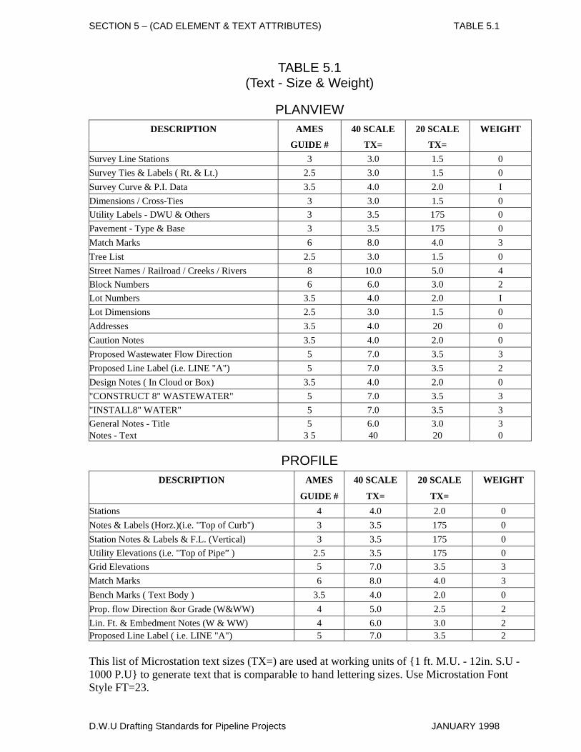
TABLE 5.1 (Text - Size & Weight)
PLANVIEW DESCRIPTION AMES 40 SCALE 20 SCALE WEIGHT
GUIDE # TX= TX= Survey Line Stations 3 3.0 1.5 0 Survey Ties & Labels ( Rt. & Lt.) 2.5 3.0 1.5 0 Survey Curve & P.I. Data 3.5 4.0 2.0 I Dimensions / Cross-Ties 3 3.0 1.5 0 Utility Labels - DWU & Others 3 3.5 175 0 Pavement - Type & Base 3 3.5 175 0 Match Marks 6 8.0 4.0 3 Tree List 2.5 3.0 1.5 0 Street Names / Railroad / Creeks / Rivers 8 10.0 5.0 4 Block Numbers 6 6.0 3.0 2 Lot Numbers 3.5 4.0 2.0 I Lot Dimensions 2.5 3.0 1.5 0 Addresses 3.5 4.0 20 0 Caution Notes 3.5 4.0 2.0 0 Proposed Wastewater Flow Direction 5 7.0 3.5 3 Proposed Line Label (i.e. LINE "A") 5 7.0 3.5 2 Design Notes ( In Cloud or Box) 3.5 4.0 2.0 0 "CONSTRUCT 8" WASTEWATER" 5 7.0 3.5 3 "INSTALL8" WATER" 5 7.0 3.5 3 General Notes - Title 5 6.0 3.0 3 Notes - Text 3 5 40 20 0
PROFILE DESCRIPTION AMES 40 SCALE 20 SCALE WEIGHT
GUIDE # TX= TX= Stations 4 4.0 2.0 0 Notes & Labels (Horz.)(i.e. "Top of Curb") 3 3.5 175 0 Station Notes & Labels & F.L. (Vertical) 3 3.5 175 0 Utility Elevations (i.e. "Top of Pipe” ) 2.5 3.5 175 0 Grid Elevations 5 7.0 3.5 3 Match Marks 6 8.0 4.0 3 Bench Marks ( Text Body ) 3.5 4.0 2.0 0 Prop. flow Direction &or Grade (W&WW) 4 5.0 2.5 2 Lin. Ft. & Embedment Notes (W & WW) 4 6.0 3.0 2 Proposed Line Label ( i.e. LINE "A") 5 7.0 3.5 2 This list of Microstation text sizes (TX=) are used at working units of {1 ft. M.U. - 12in. S.U - 1000 P.U} to generate text that is comparable to hand lettering sizes. Use Microstation Font Style FT=23.
D.W.U Drafting Standards for Pipeline Projects JANUARY 1998
SECTION 5 – (CAD ELEMENT & TEXT ATTRIBUTES) TABLE 5.2
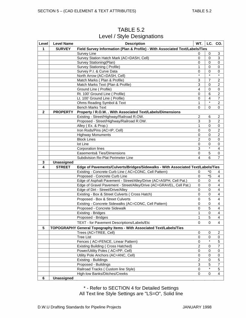
TABLE 5.2 Level / Style Designations
Level Level Name Description WT. LC. CO.1 SURVEY Field Survey Information (Plan & Profile) - With Associated Text/Labels/Ties Survey Line 0 0 3 Survey Station Hatch Mark (AC=DASH, Cell) 0 0 3 Survey Stationing(Plan) 0 0 0 Survey Stationing ( Profile) 1 0 0 Survey P.I. & Curve Data 0 0 0 North Arrow (AC=DASH, Cell) * * * Match Marks ( Plan & Profile) 3 7 2 Match Marks Text (Plan & Profile) 3 0 2 Ground Line ( Profile) 4 0 0 Rt. 100' Ground Line ( Profile) 0 6 2 Lt. 100' Ground Line ( Profile) 0 4 7 Ohms Reading Symbol & Text 1 * 2 Bench Marks Text 0 0 0
2 PROPERTY Property / R.O.W. . With Associated Text/Labels/Dimensions Existing - Street/Highway/Railroad R.OW. 2 6 2 Proposed - Street/Highway/Railroad R.OW. 3 3 2 Alley ( Ex. & Prop.) 1 0 0 Iron Rods/Pins (AC=IP, Cell) 0 0 2 Highway Monuments 0 0 2 Block Lines 2 0 0 lot Line 0 0 0 Corporation lines 3 * 4 Easements& Ties/Dimensions 0 5 0 Subdivision Re-Plat Perimeter Line 4 6 7
3 Unassigned 4 STREET Edge of Pavements/Culverts/Bridges/Sidewalks - With Associated Text/Labels/Ties Existing - Concrete Curb Line ( AC=CONC, Cell Pattern) 0 *0 4 Proposed - Concrete Curb Line 0 *5 4 Edge of Asphalt Pavement - Street/Alley/Drive (AC=ASPH, Cell Pat.) 0 0 4 Edge of Gravel Pavement - Street/Alley/Drive (AC=GRAVEL, Cell Pat.) 0 0 4 Edge of Dirt - Street/Drive/Alley 0 0 4 Existing - Box & Street Culverts ( Cross Hatch) 0 0 4 Proposed - Box & Street Culverts 0 5 4 Existing - Concrete Sidewalks (AC=CONC, Cell Pattern) 0 0 4 Proposed - Concrete Sidewalk 0 5 4 Existing - Bridges 1 0 4 Proposed - Bridges 1 5 4 TEXT - for Pavement Descriptions/Labels/Etc 0 0 4
5 TOPOGRAPHY General Topography Items - With Associated Text/Labels/Ties Trees (AC=TREE, Cell) 0 0 2 Tree List 0 0 0 Fences ( AC=FENCE, Linear Pattern) 0 * 5 Existing Building ( Cross Hatched) 2 0 7 Power/Utility Poles ( AC=PP, Cell) 0 0 0 Utility Pole Anchors (AC=ANC, Cell) 0 0 0 Existing - Buildings 2 0 5 Proposed - Buildings 3 5 7 Railroad Tracks ( Custom line Style) 0 * 5 High-low Banks/Ditches/Creeks 0 0 4
6 Unassigned
* - Refer to SECTION 4 for Detailed Settings All Text line Style Settings are "LS=O", Solid line
D.W.U Drafting Standards for Pipeline Projects JANUARY 1998
SECTION 5 – (CAD ELEMENT & TEXT ATTRIBUTES) TABLE 5.2
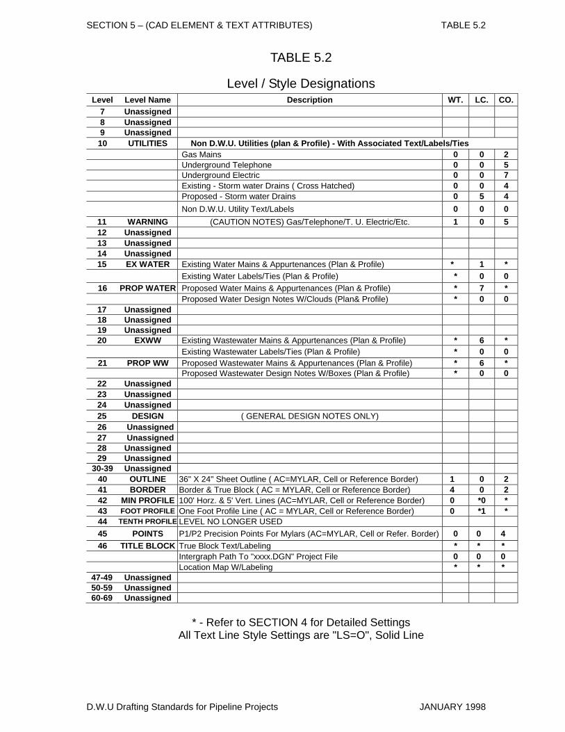
TABLE 5.2
Level / Style Designations Level Level Name Description WT. LC. CO.
7 Unassigned 8 Unassigned 9 Unassigned 10 UTILITIES Non D.W.U. Utilities (plan & Profile) - With Associated Text/Labels/Ties Gas Mains 0 0 2 Underground Telephone 0 0 5 Underground Electric 0 0 7 Existing - Storm water Drains ( Cross Hatched) 0 0 4 Proposed - Storm water Drains 0 5 4 Non D.W.U. Utility Text/Labels 0 0 0
11 WARNING (CAUTION NOTES) Gas/Telephone/T. U. Electric/Etc. 1 0 5 12 Unassigned 13 Unassigned 14 Unassigned 15 EX WATER Existing Water Mains & Appurtenances (Plan & Profile) * 1 *
Existing Water Labels/Ties (Plan & Profile) * 0 0 16 PROP WATER Proposed Water Mains & Appurtenances (Plan & Profile) * 7 * Proposed Water Design Notes W/Clouds (Plan& Profile) * 0 0
17 Unassigned 18 Unassigned 19 Unassigned 20 EXWW Existing Wastewater Mains & Appurtenances (Plan & Profile) * 6 *
Existing Wastewater Labels/Ties (Plan & Profile) * 0 0 21 PROP WW Proposed Wastewater Mains & Appurtenances (Plan & Profile) * 6 * Proposed Wastewater Design Notes W/Boxes (Plan & Profile) * 0 0
22 Unassigned 23 Unassigned 24 Unassigned 25 DESIGN ( GENERAL DESIGN NOTES ONLY) 26 Unassigned 27 Unassigned 28 Unassigned 29 Unassigned
30-39 Unassigned 40 OUTLINE 36" X 24" Sheet Outline ( AC=MYLAR, Cell or Reference Border) 1 0 2 41 BORDER Border & True Block ( AC = MYLAR, Cell or Reference Border) 4 0 2 42 MIN PROFILE 100' Horz. & 5' Vert. Lines (AC=MYLAR, Cell or Reference Border) 0 *0 * 43 FOOT PROFILE One Foot Profile Line ( AC = MYLAR, Cell or Reference Border) 0 *1 * 44 TENTH PROFILE LEVEL NO LONGER USED 45 POINTS P1/P2 Precision Points For Mylars (AC=MYLAR, Cell or Refer. Border) 0 0 4 46 TITLE BLOCK True Block Text/Labeling * * * Intergraph Path To "xxxx.DGN" Project File 0 0 0 Location Map W/Labeling * * *
47-49 Unassigned 50-59 Unassigned 60-69 Unassigned
* - Refer to SECTION 4 for Detailed Settings
All Text Line Style Settings are "LS=O", Solid Line
D.W.U Drafting Standards for Pipeline Projects JANUARY 1998
SECTION 5 – (CAD ELEMENT & TEXT ATTRIBUTES) TABLE 5.3
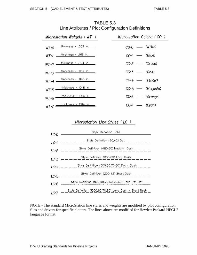
TABLE 5.3 Line Attributes / Plot Configuration Definitions
NOTE - The standard MicroStation line styles and weights are modified by plot configuration files and drivers for specific plotters. The lines above are modified for Hewlett Packard HPGL2 language format.
D.W.U Drafting Standards for Pipeline Projects JANUARY 1998
SECTION 5 – (CAD ELEMENT & TEXT ATTRIBUTES) TABLE 5.4
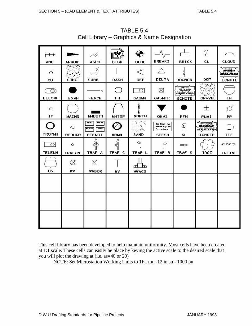
TABLE 5.4 Cell Library – Graphics & Name Designation
This cell library has been developed to help maintain uniformity. Most cells have been created at 1:1 scale. These cells can easily be place by keying the active scale to the desired scale that you will plot the drawing at (i.e. as=40 or 20) NOTE: Set Microstation Working Units to 1Ft. mu -12 in su - 1000 pu
D.W.U Drafting Standards for Pipeline Projects JANUARY 1998
SECTION 6
(Drawing Examples)
LEGEND for MicroStation Key-In AC = Active Cell CO = Color LC = Line Code (Style) LV = Level Designation TX = Text Size WT = Weight
D.W.U Drafting Standards for Pipeline Projects JANUARY 1998
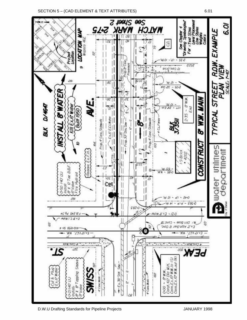
SECTION 5 – (CAD ELEMENT & TEXT ATTRIBUTES) 6.01
D.W.U Drafting Standards for Pipeline Projects JANUARY 1998
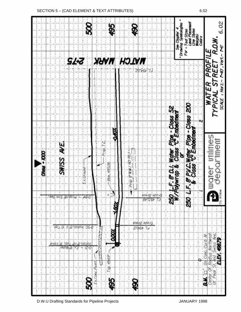
SECTION 5 – (CAD ELEMENT & TEXT ATTRIBUTES) 6.02
D.W.U Drafting Standards for Pipeline Projects JANUARY 1998
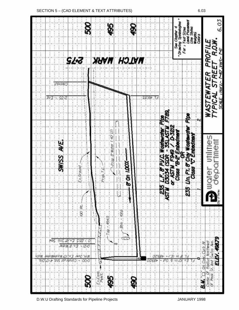
SECTION 5 – (CAD ELEMENT & TEXT ATTRIBUTES) 6.03
D.W.U Drafting Standards for Pipeline Projects JANUARY 1998
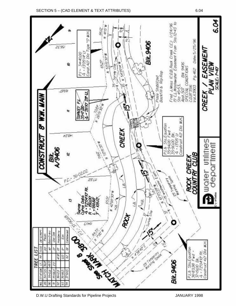
SECTION 5 – (CAD ELEMENT & TEXT ATTRIBUTES) 6.04
D.W.U Drafting Standards for Pipeline Projects JANUARY 1998
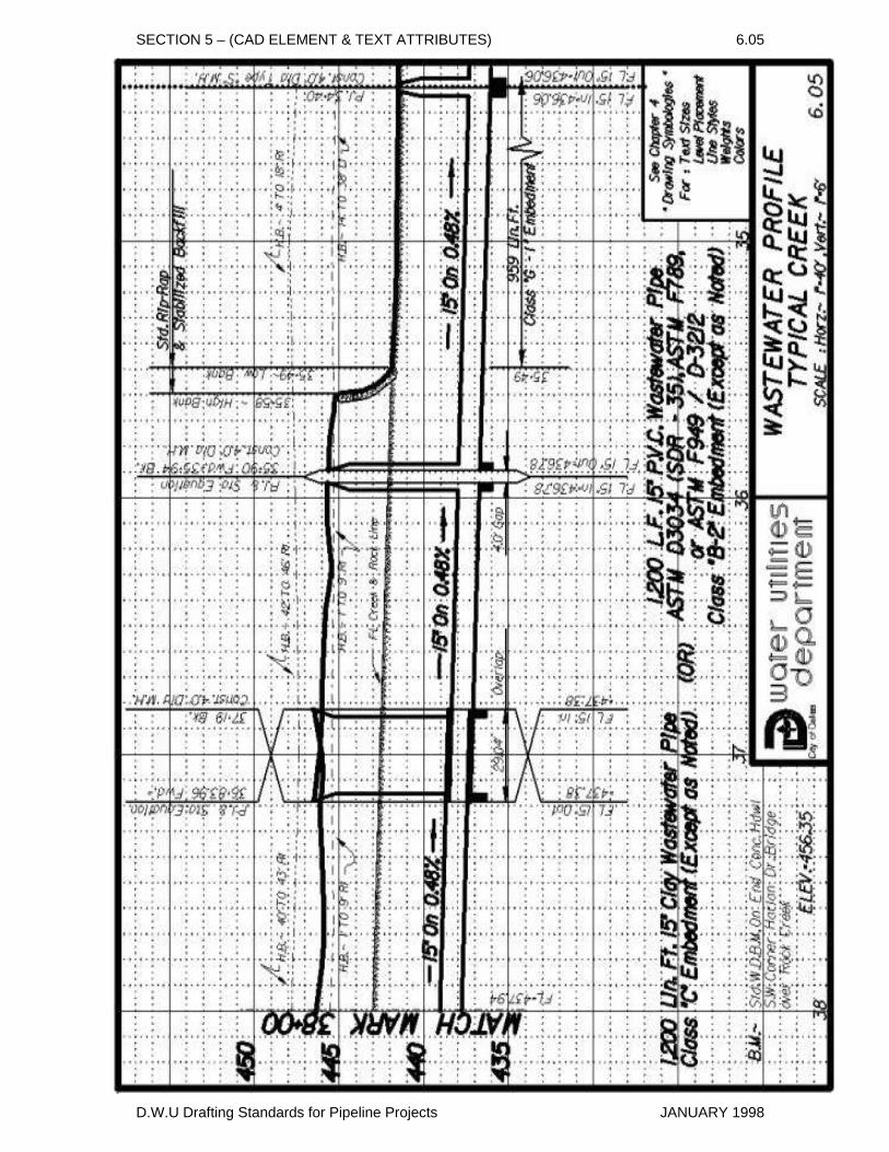
SECTION 5 – (CAD ELEMENT & TEXT ATTRIBUTES) 6.05
D.W.U Drafting Standards for Pipeline Projects JANUARY 1998
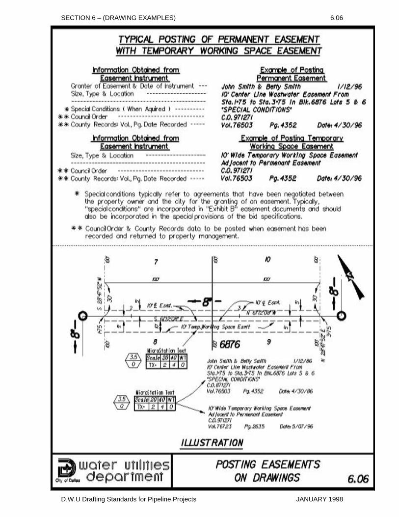
SECTION 6 – (DRAWING EXAMPLES) 6.06
D.W.U Drafting Standards for Pipeline Projects JANUARY 1998
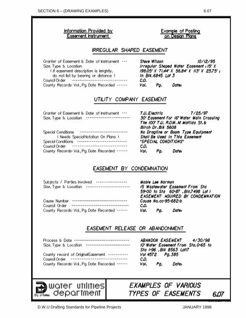
SECTION 6 – (DRAWING EXAMPLES) 6.07
D.W.U Drafting Standards for Pipeline Projects JANUARY 1998
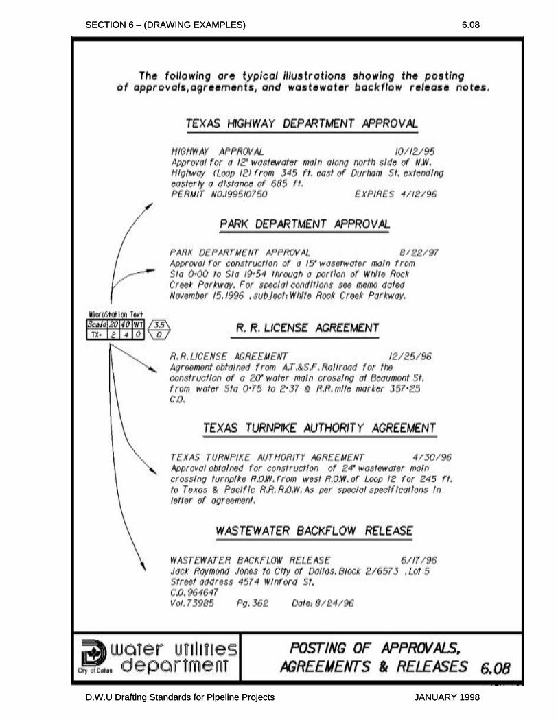
SECTION 6 – (DRAWING EXAMPLES) 6.08 SECTION 6 – (DRAWING EXAMPLES) 6.08
D.W.U Drafting Standards for Pipeline Projects JANUARY 1998
D.W.U Drafting Standards for Pipeline Projects JANUARY 1998