City of Akron Consent Decree CMOM Program · FSE Food Service Establishment GIS Geographic...
185
Department of Public Service Akron Engineering Bureau Environmental Division File: 2010-010-00 City of Akron Consent Decree CMOM Program May 10, 2010 Revised: August 10, 2012 Mayor Donald L. Plusquellic Service Director Richard A. Merolla
Transcript of City of Akron Consent Decree CMOM Program · FSE Food Service Establishment GIS Geographic...

Department of Public Service Akron Engineering Bureau
Environmental Division
File: 2010-010-00
City of Akron
Consent Decree CMOM Program
May 10, 2010 Revised: August 10, 2012
Mayor Donald L. Plusquellic
Service Director Richard A. Merolla


Revision History
Revision Revision Date Details Authorized Name/Company
1 2012/08/10 CMOM Program Re-submittal Daniel R. Johnson, PE / Burgess & Niple, Inc.

List of Abbreviations Executive Summary 1. Program Development 2. Consent Decree Elements Appendices
A. Standard Operating Procedures
B. Documents and Forms
C. GIS Standards and Procedures
D. Datastream Manuals
E. Semi-Annual Reporting Tracking Sheet
TABLE OF CONTENTS


CMOM Program City of Akron August 2012
i
LIST OF ABBREVIATIONS ASB Akron Sewer Bureau ARV Air Release Valves BCE Business Case Evaluation CA Condition Assessment CCTV Closed Circuit Television CD Consent Decree CIP Capital Improvement Project CMOM Capacity, Management, Operations and Maintenance CMMS Computer-based Maintenance Management System cSAM Collection System Assessment Manager CSO Combined Sewer Overflow CSS Combined Sewer System CSSR Combined Sewer System Release EPA Environmental Protection Agency ERP Emergency Response Plan (also known as SORNP) FOG Fats, Oils and Grease FSE Food Service Establishment GIS Geographic Information System I/I Infiltration and Inflow LTCP Long-Term Control Plan MOM Management, Operations and Maintenance (elements of a CMOM Program) NASSCO North America Sewer Services Companies NPDES National Pollutant Discharge Elimination System Ohio EPA Ohio Environmental Protection Agency O&M Operation and Maintenance PACP Pipeline Assessment and Certification Program PM Preventive Maintenance PMP Preventative Maintenance Program RCA Root Cause Analysis RP Record Plan (Record drawings of sewer construction) R&R Rehabilitation and Replacement SCADA Supervisory Control and Data Acquisition SOP Standard Operating Procedures SO Sewer Overflow SORNP Sewer Overflow Response and Notification Plan SSO Sanitary Sewer Overflow USEPA United States Environmental Protection Agency WO Work Order WPCS Water Pollution Control Station

ES-1
C I T Y O F A K R O N C M O M P R O G R A M R E P O R T
E X E C U T I V E S U M M A R Y
The City of Akron (the City) has made significant investments in its sewer system in the past several decades. The City is also planning more improvements during the coming years to address the needs of its customers and the system. On November 13, 2009, a Consent Decree between the City, the United States (on behalf of the Environmental Protection Agency (USEPA)) and the State of Ohio (on behalf of the Ohio EPA) was lodged with the United States District Court for the Northern District of Ohio, Eastern Division (the Consent Decree). The parties expect the court to enter the Consent Decree in the near future.
Pursuant to Section VII of the Consent Decree, the City has agreed to implement a Capacity, Management, Operations and Maintenance (CMOM) program. The elements for these programs are set forth in Attachment C of the Consent Decree.
The City followed a systematic methodology to determine the level of implementation for elements in Attachment C of the Consent Decree. The City will use the CMOM Program to help structure improvements to the City’s collection system and correct system deficiencies or practices that may contribute to or result in sewer overflows.
Table ES.1 summarizes the elements of the Consent Decree, as listed in Attachment C, paragraph 2.
Table ES.1 Consent Decree Elements
Paragraph Consent Decree Item A) Maintaining a complete Sewer System component and equipment inventory; B) A daily CSO Rack inspection and cleaning program; C) A condition assessment consisting of routine proactive inspection of the Sewer System including:
(i) inspection of each gravity sewer pipe in high-maintenance areas, and each gravity sewer pipe that experiences a blockage leading to an SSO, using CCTV or other appropriate inspection methods (excluding lamping) as soon as is practicable but no later than two (2) weeks following the SSO;
(ii) CCTV inspection leading up to at least 20% of all gravity sewer pipe each year, starting with 10% in Year 1, 15% in Year 2, and 20% in subsequent years, with CCTV inspection of all gravity sewer pipe in the Sewer System, which shall include CCTV’ing performed by Akron during calendar year 2008 through the date of U.S. EPA approval of the Collection System CMOM Program, not later than December 31, 2014;
(iii) inspection of all manholes in the Sewer System every five (5) years, which shall include manhole inspections performed by Akron during calendar year 2008 through the date of U.S. EPA approval of the Collection System CMOM Program, not later than December 31, 2014; and
(iv) preparation of condition assessment reports following CCTV inspections that, at a minimum, document the following: (i) Defects that materially threaten the structural integrity of the pipe or structure; (ii) Defects that allow infiltration, inflow, or exfiltration; (iii) Pipe defects, including but not limited to, cracks, holes, corrosion, misaligned joints, root intrusion, sags, improper lateral taps, or
other defects that make the pipe or structure prone to grease, root, or debris blockages; (iv) A rank or score of the condition of each inspected pipe or structure on a sliding scale that indicates the severity of any defects
found; (v) Whether the pipe or structure requires either short or long-term repair; (vi) Changes to cleaning frequency as a result of the assessment; and
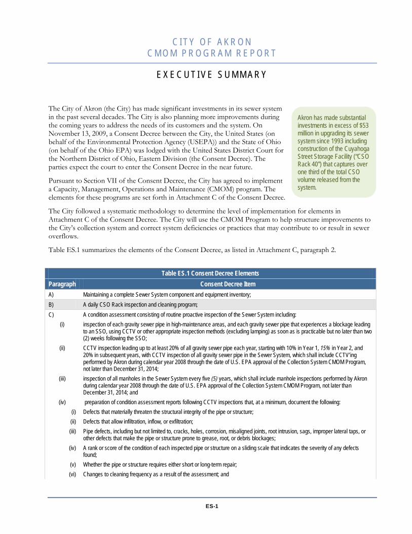
Akron has made substantial investments in excess of $53 million in upgrading its sewer system since 1993 including construction of the Cuyahoga Street Storage Facility (“CSO Rack 40”) that captures over one third of the total CSO volume released from the system.

Executive Summary CMOM Program City of Akron August 2012
ES-2
Table ES.1 Consent Decree Elements Paragraph Consent Decree Item
(vii) An estimate of the expected remaining service life of the pipe or structure. D) Cleaning gravity sewer lines as necessary Additionally, Akron shall:
(i) complete one (1) cleaning of each gravity sewer pipe in the City’s Sewer System by December 31, 2014, which shall include gravity sewer line cleaning performed by Akron during calendar year, 2008; and
(ii) continue with ongoing cleaning of each gravity sewer pipe in the City’s Sewer System on a minimum five (5) year frequency; E) Routine annual preventative maintenance of Pumping Stations and Force Mains; F) Sealing (where appropriate) and maintenance of manholes; G) Identification and remediation of poor construction; H) Procedures for ensuring that new sewers and connections are properly designed and constructed (including testing of new sewer
installations) to prevent overflows and to ensure that new connections of inflow sources are prohibited; I) Procedures for ensuring that repair, rehabilitation and replacement projects are properly designed and constructed (including
testing of rehabilitation installations) to prevent overflows, including; (i) repair of all acute defects (i.e., those defects that have caused or substantially increase the probability of an SSO or CSS Release,
including conditions leading to imminent structural collapse or that would create repeated blockages) within one (1) year of discovery of the defect. Akron shall maintain a log listing all sewer line acute defects in need of expeditious repair or replacement, the date the City discovered the acute defect, an estimated schedule for performing the repair or replacement, and the date of project completion;
(ii) a schedule to address defective pipes that is based on the results of the condition assessment required under Paragraph 2 (B) and a schedule under which Akron shall replace, rehabilitate, or permanently repair any other pipes necessary to reduce the risks of SSOs and CSS Releases and ensure the long-term sustainable renewal of the City’s infrastructure. Permanent repair means the correction of a structural defect in a manhole to manhole pipe segment such that the repair has the same life expectancy as a rehabilitated pipe; and
(iii) maintenance of a log listing each sewer pipe and structure project completed during the previous year and the date the project was completed;
J) A grease control program that, at a minimum, includes the following: (i) Procedures for identifying and mitigating fats, oil, and grease (FOG) trouble spots throughout the collection system. Akron shall
prepare and maintain a list of FOG trouble spots in the collection system, identifying the specific pipe segments where FOG trouble spots are found. This list shall include an accelerated inspection and cleaning program for these trouble spots. Akron shall develop a methodology to categorize and prioritize the FOG trouble spots and develop inspection and cleaning schedules for these trouble spots. Akron shall use this methodology to update annually its list of FOG trouble spots, including the inspection and cleaning schedules.
(ii) Procedures for coordinating with the Akron Health Department and the Summit County Health Department to conduct inspections and take follow-up actions for FOG trouble spots that are determined to be caused by Food Establishments. When trouble spots are identified to be caused by a Food Establishment, Akron shall follow these procedures to ensure that the Food Establishment installs proper FOG control devices to prevent excess FOG discharges to the Sewer System. For these Food Establishments, Akron shall also ensure onsite record keeping at the Establishments, including but not limited records of the dates of grease removal, the amount of grease removed, and the location where the Food Establishment disposed of the grease and the name, address, and phone number of the hauling or recycling service used to transport the grease. Akron shall maintain a list of all Food Establishments determined to be the cause of FOG trouble spots and the specific actions taken to ensure that those Food Establishments install proper FOG control devices.
(iii) Educational efforts aimed at FOG sources and, if appropriate, residential users, and recommendations for changes to public education, outreach and compliance efforts to inform commercial, institutional and residential property owners and tenants about the need to minimize the introduction of grease into the Sewer System.
K) A root control program that addresses, at a minimum, scheduling and performing corrective measures including both short-term mitigation of root intrusion (i.e., routine maintenance) and rehabilitation of the areas in which root intrusion has caused recurring blockages (i.e., sewer replacement or relining), and a proposal that includes scheduled inspection of known problem areas;
L) Description of a method for documenting complaints, work orders, updates to equipment inventory, and changes to Sewer System components, as well as entry of such data into a data management system that allows ready use of the information including the capability of scheduling and tracking both preventative and reactive maintenance activities;

Executive Summary CMOM Program City of Akron August 2012
ES-3
Table ES.1 Consent Decree Elements Paragraph Consent Decree Item M) Corrective maintenance response and reporting procedures; N) Adequate training of staff and adequate equipment to ensure that Akron promptly identifies and addresses problems in its Sewer
System that lead to SSOs and CSS Releases. Within two (2) Years following the Date of Lodging of this Consent Decree, Akron shall ensure that at least one member of each CCTV crew has attained Pipe Assessment Certification Program (PACP) certification;
O) Description of a “root cause analysis” process for situations in which the City’s Sewer System failed to perform as designed or resulted in an SSO or CSS Release. This process shall include the documentation of all the known operational variables that lead to the failure in performance of the Sewer System or the SSO or CSS Release event; and
P) An annual update of the operation and maintenance manuals.


1-1
C I T Y O F A K R O N C M O M P R O G R A M R E P O R T
1 . P R O G R A M D E V E L O P M E N T
1.1 Overview On November 13, 2009, a Consent Decree between the City, the United States (on behalf of the Environmental Protection Agency (USEPA)) and the State of Ohio (on behalf of the Ohio EPA) was lodged with the United States District Court for the Northern District of Ohio, Eastern Division (the Consent Decree). The parties expect the court to enter the Consent Decree in the near future.
Pursuant to Section VII of the Consent Decree, the City has agreed to implement a Capacity, Management, Operations and Maintenance (CMOM) program. The details for these programs are set forth in Attachment C of the Consent Decree. The Consent Decree requires the City to submit a CMOM Program to the Ohio EPA and the USEPA within 180 days from the lodging of the Consent Decree, or May 12, 2010. This report addresses the Management, Operations and Maintenance components of the City’s program. This CMOM Program Report satisfies the requirement of the City to submit a comprehensive CMOM Program. The program includes details regarding each element in Attachment C, paragraphs 2.A to 2.P, of the Consent Decree.
The City completed an initial assessment of its existing practice areas. Based on the information gathered during the assessment phase, the status of the City’s existing practices and programs was determined, as they applied to the Consent Decree.
The City performed a Readiness Review that included an evaluation of current practices. The review determined the level of implementation of the Consent Decree elements identified in Attachment C. During this phase the City collected and reviewed existing documents, conducted staff interviews, and observed the crews performing typical work duties. The results were compiled, analyzed and summarized so further discussion with the City staff could be carried out to verify the accuracy of the information. This report contains a summary of the program and practices that address each element set forth in elements 2.A to 2.P, of Attachment C of the Consent Decree. The City will use the results of this assessment to identify program deficiencies that need improvement to reach full implementation of these Consent Decree elements, specific activities for improvements, steps needed to correct the identified deficiencies, prioritization of the activities to be addressed and fixed-date milestones, where appropriate, for initiating and completing those steps.
1.2 Readiness Review ProcesThe City’s objectives for the CMOM Program are to ensure that the wastewater system is operated to its fullest capabilities and to satisfy the terms of the Consent Decree. These objectives present significant technical and organizational challenges that will affect the future of Akron and its customers. To help meet that challenge the City performed a Readiness Review. The Readiness Review process was focused on determining the underlying causes of sewer overflows and was intended to identify CMOM practices that can be improved to minimize or eliminate overflow occurrences in the future. The systematic approach to conducting a Readiness Review included reviewing relevant documents, performing staff interviews and performing field observations of the City crews. A worksheet listing Akron-relevant criteria was developed based on the requirements of the Consent Decree. The information collected during the Readiness Review was compared to the requirements of the Consent Decree to determine the level of implementation of those requirements.
s

Executive Summary CMOM Program City of Akron August 2012
1-2
1.2.1 Records Review
Strategic documents, program documents, standard procedures, and a representative sample of records, reports, and work orders were reviewed. The records review was oriented toward developing brief summaries, programs, and procedures that were used to describe and document the adequacy of the City’s current CMOM Program elements. Additionally, the records review process provided a yardstick against which personnel interviews and field observations were compared.
1.2.2 Staff Interviews
A series of interviews was conducted with staff members representing a diagonal slice (top to bottom) of those responsible for sewer system operations and maintenance. The purpose of these interviews was to develop a better understanding of the City’s management philosophy and the current goals for customer service, regulatory compliance, asset management, and workflow protocols. The interviews were also conducted to assess the current state of the City’s management, operations, and maintenance programs; the existing information systems; and the inter-divisional coordination and communications. In addition to a description of the current practices performed by the employees, the employees’ perceptions of work management and other concerns were documented during the interviews.
1.2.3 Field Observations
Observations of field and on-site activities were made to assess whether field procedures were consistent with established policies and practices and to validate information documented during staff interviews. The field observations provided insight to work practices, general conditions the crews faced, technologies used, and provided an understanding of other technical, operational or maintenance issues. The observations focused on opportunities for improvement that will help to ensure the system is operated to its fullest capabilities and to facilitate Consent Decree implementation.
1.2.4 Readiness Review Assessment Documentation Process
Based on what was read, heard and seen during the Readiness Review Process, the City’s current practices were compared against the requirements of the Consent Decree. The level of implementation, or the degree to which a program was developed, was assessed and discussed further with a group of City staff members. The purpose of that discussion was to gather additional information, and to reach a consensus on the status of the City’s programs. A systematic process was used to determine the current level of implementation and identify what the City needs to do to help ensure the system is operated to its fullest capabilities, and to meet the requirements of each Consent Decree element related to the CMOM Program.
Additionally, time was taken during that discussion to identify the initial priorities of the elements that should be addressed first to comply with the requirements of the Consent Decree. In some cases, the higher priority areas represented practices and activities where improvement could be achieved in the short-term, resulting in “early gains.” In other cases, long-term implementation activities will have goal dates for completion, where feasible, to assist in directing implementation of the CMOM Program and will be updated through the Semi-Annual reporting process.
The City provided relevant documents for review during the Readiness Review Process.

2-1
C I T Y O F A K R O N C M O M P R O G R A M R E P O R T
2 . C O N S E N T D E C R E E E L E M E N T S
Attachment C of the Consent Decree identifies the specific elements that need to be included in the City’s CMOM Program. In this section, each element of the Consent Decree Attachment C, paragraph 2.A to 2.P is introduced along with a discussion of the City’s implementation of the elements. This discussion includes three topics: the status of the element including a brief background about the Consent Decree element, any expected future activities or steps required (if necessary) to reach full implementation, and a schedule to achieve full implementation.
Status
By definition the Akron sewer system includes “the wastewater collection and conveyance system owned or operated by Akron (including all pipes, force mains, gravity sewer segments, pump stations, manholes, and appurtenances thereto) that is designed to collect and convey municipal sewage (domestic, commercial, or industrial) to the WPCS or to a CSO Outfall. ‘Sewer System’ does not include any Private Service Connection Lateral.”
The City maintains an inventory of the system components and equipment on various paper and electronic database systems. Information can be found in the following formats: Sewer System Maps (Undergrounds) and Record Drawings; a Geographical Information System (GIS); a Computerized Maintenance Management System (CMMS) software package (Datastream 7i); and FleetFocus (or Vehicle CMMS), a CMMS program used for vehicle maintenance, repair monitoring and control.
Documents
Asset information is maintained on paper documents including sewer system maps, record drawings and the Pump Station Notebook. The notebook includes maps showing the locations of pump stations, equipment information, length and size of force mains, photographs of the pump stations and drawings of the racks. A summary spreadsheet, which includes pump station information, has been created and is used by the City (see Appendix B for samples from the Pump Station Notebook). Field personnel use “underground” maps to locate sewer system components for performing maintenance activities. Contractors or City personnel, upon completion of a project involving installation of new sewer components, extensions of sewers or repair of sewer segments and components, provide record drawings to the City.
2.A.
Maintaining a complete Sewer System component and equipment inventory;
Attachment C. Measures to Maximize Sewer System Performance and Eliminate SSOs and CSS Release Capacity, Management, Operation, and Maintenance Program
2. No later than 180 days from the Date of Lodging, Akron shall submit to U.S. EPA and OEPA for review and approval, in accordance with the requirements of Section XVII, a comprehensive Collection System Capacity, Management, Operation, and Maintenance (CMOM) Program. This Program shall be limited to, and only include, Akron-owned separate and combined portions of its Sewer System. The Collection System CMOM Program shall include, at a minimum, the following elements: A to P.

Section 2 CMOM Program City of Akron August 2012
2-2
Geographical Information System (GIS)
GIS provides the geographical location of structures and defines the physical sewer components. It is used to provide the following attributes for the Akron sewer system: Pipes – size, type, length Manholes – size, construction type Valves – size, type Valve vaults – type Pump stations locations Rack locations (combined sewer system overflow regulators)
Sewer system assets are listed in GIS, but some asset attributes are not fully documented (e.g., pipe size, pipe material, etc. for various pipe segments or assets). The City has an on-going effort to populate missing attributes in GIS. The City continually enters the relevant information from record construction drawings into the GIS as this information is discovered during ongoing maintenance activities. Since the entire system will be inspected by the end of 2014, the goal is for all existing assets to be identified through the inspection process and entered into GIS by December 31, 2015. A Standard Operating Procedure (SOP) GIS Record Drawing Data Entry and a GIS Standards and Procedures Document have been developed for updating GIS from the record drawings to assist this process. (See Appendix A for SOPs and Appendix C for the GIS Standards and Procedures.)
Computerized Maintenance Management System (Datastream 7i)
The CMMS is used to
SM001 – Maintenance: includes equipment and materials (flushing hose, nozzles, root cutters, couplings, etc.) used by the Sewer Maintenance crews in completing their assigned tasks.
track maintenance work performed and costs on the sewer system equipment and components, and to keep the inventory of spare parts (see Appendix D for copies of the APUB Datastream Manual). The City is in the process of upgrading the software to Infor EAM. The inventory system for the pump stations, maintained in GIS and CMMS, utilizes a “parent-child” relationship for connecting the various assets listed in the separate inventory databases. GIS and the CMMS are used in combination to provide this relationship. Spare parts are assigned to the different “storerooms.” There are six inventories maintained by the Sewer Maintenance Division in this software. Sample storeroom inventory printouts are included in Appendix B.
SM002 – TV: includes equipment, parts and materials used by the Sewer Televising crews during normal work activities.
SM003 – Construction: includes equipment and materials (pipe, fittings, repair clamps, manhole/inlet castings; risers; bricks, etc.) used in sewer construction and repair work.
SM004 – not used SM005 – Pump Station Non-Inventory; contains parts not commonly used to maintain the pump stations SM005a – Pump Station: contains the parts and equipment used in maintaining the pump stations (impellers, wear
plates, bearings, belts, sheaves, electrical parts, floats, etc.). SM006 – Non-Inventory: includes items used within the administration building and shop not assigned to another
inventory storeroom.
Several documents and procedures are in place to help maintain an inventory of the sewer system. There are SOPs written and in place for the following tasks: Entering Parts Into Inventory and Charging Them to Work Orders; Items Received and Items Used; Storeroom; Conducting Annual Inventory of Equipment and Spare Parts; and Commissioning and Decommissioning of Inventory Asset. (See Appendix A. SOPs, Appendix B for sample inventory lists and Appendix D for sample screen shots from the APUB CFO Datastream 7i Extended Training Guide.)
Section 2 CMOM Program City of Akron August 2012
2-3
CMMS is updated as needed to keep the program current and to make improvements. For example, at pump stations, wet wells are not identified as a separate asset, so the City is adding wet wells as a child asset to the parent pump station. Force main air valves have been identified as separate attributes of the air valve manholes in GIS.
Computerized Maintenance Management System for Vehicles (FleetFocus)
FleetFocus
Fleet vehicles are included on the inventory;
software is used throughout the City to track and inventory fleet vehicles, and to operate as a CMMS for vehicle maintenance (see Appendix B for a list of vehicles).
Motorized and rolling stock (trailers, compressors) equipment is included in the inventory; and Spare parts for sewer system O&M may be assigned to vehicles (“rolling storerooms”). SM-HOME – Inventory items purchased for vehicles with Sewer Maintenance purchase orders. SM-MOTO – Inventory items purchased for vehicles with Motor Equipment purchase orders.
Replacement of vehicles is typically based on age, mileage, condition, frequency of use and criticality.
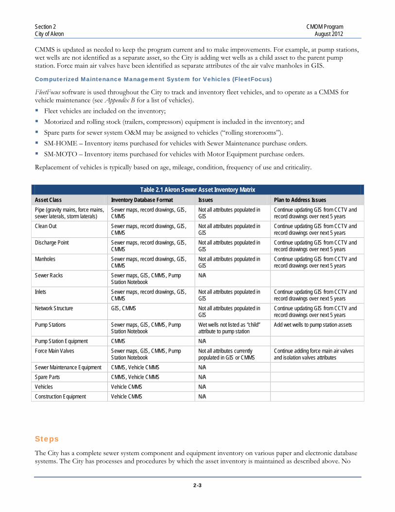
Table 2.1 Akron Sewer Asset Inventory Matrix
Asset Class Inventory Database Format Issues Plan to Address Issues Pipe (gravity mains, force mains, sewer laterals, storm laterals)
Sewer maps, record drawings, GIS, CMMS
Not all attributes populated in GIS
Continue updating GIS from CCTV and record drawings over next 5 years
Clean Out Sewer maps, record drawings, GIS, CMMS
Not all attributes populated in GIS
Continue updating GIS from CCTV and record drawings over next 5 years
Discharge Point Sewer maps, record drawings, GIS, CMMS
Not all attributes populated in GIS
Continue updating GIS from CCTV and record drawings over next 5 years
Manholes Sewer maps, record drawings, GIS, CMMS
Not all attributes populated in GIS
Continue updating GIS from CCTV and record drawings over next 5 years
Sewer Racks Sewer maps, GIS, CMMS, Pump Station Notebook
N/A
Inlets Sewer maps, record drawings, GIS, CMMS
Not all attributes populated in GIS
Continue updating GIS from CCTV and record drawings over next 5 years
Network Structure GIS, CMMS Not all attributes populated in GIS
Continue updating GIS from CCTV and record drawings over next 5 years
Pump Stations Sewer maps, GIS, CMMS, Pump Station Notebook
Wet wells not listed as “child” attribute to pump station
Add wet wells to pump station assets
Pump Station Equipment CMMS N/A Force Main Valves Sewer maps, GIS, CMMS, Pump
Station Notebook Not all attributes currently populated in GIS or CMMS
Continue adding force main air valves and isolation valves attributes
Sewer Maintenance Equipment CMMS, Vehicle CMMS N/A Spare Parts CMMS, Vehicle CMMS N/A Vehicles Vehicle CMMS N/A Construction Equipment Vehicle CMMS N/A
Steps
The City has a complete sewer system component and equipment inventory on various paper and electronic database systems. The City has processes and procedures by which the asset inventory is maintained as described above. No

Section 2 CMOM Program City of Akron August 2012
2-4
further action is required at this time. Detailed lists of CMMS asset classes and GIS feature classes relative to the sewer system are located in Appendices C and D.
Schedule
None
Status
The intention of this requirement in the Consent Decree is to assure the City performs proactive inspection and cleaning of the CSO racks to minimize the likelihood of a dry weather overflow due to excessive debris.
At the time of this report, there are 36 CSO racks within the City of Akron’s service area. The racks are designed to catch debris from the combined sewer system at locations that allow for easy debris removal, and to reduce the chance that the underflow pipe will become clogged with debris where debris removal is more difficult. Significant modifications were made to the racks to improve the control of course solids and floatables between 1994 and 1999. This is significant since if the racks become clogged, a dry weather overflow can occur.
To reduce the likelihood of a dry weather overflow, the racks are inspected on a daily basis and if debris is found, it is removed. The rack locations and detailed drawings of each configuration are included in the O & M Manual. An SOP has been developed to outline the steps associated with the City’s rack inspection and cleaning program (see Appendix A), and is included in the Sewer Overflow Response and Notification Plan (SORNP) submitted to EPA on February 11, 2010. The crew notes the findings of the inspection, including the type of debris found, on a Rack Inspection Form (see Appendix B) and the information is transferred to the CMMS to track the findings, and record information detailing maintenance activities, such as cleaning, performed by the crews. The amount of debris removed from the rack, in units of garbage bags, is also tracked on the inspection sheet. Additionally, the crews typically note on the inspection sheet the type of debris that is found on the racks. The regular rack inspection crew has a good understanding of which racks are most susceptible to heavy debris accumulation and pay particular attention to those locations, especially after a significant rain event.
All thirty-six of the rack locations are remotely monitored with level sensors connected to the SCADA system, which is monitored in the Sewer Maintenance dispatch office. Pump Station crews maintain the SCADA system and the instrumentation. The sensors are calibrated regularly to verify that the levels are accurately recorded. During an overflow event, the level readings are used to calculate the volume of overflow, which is reported on the Monthly Operating Report. If, during dry weather, an overflow alarm at a rack is registered on the SCADA system, that location is inspected as soon as possible, even after normal business hours, to eliminate the potential for a dry weather overflow. Another form, the Dry Weather Rack Overflow Responses form (Appendix B), is used to track information about the alarm, the findings of a response to an alarm at a CSO Rack and the OEPA Incident Number if an actual overflow has
2.B.
A daily CSO Rack inspection and cleaning program;
One of Akron’s CSO Racks.

Section 2 CMOM Program City of Akron August 2012
2-5
occurred. The SCADA system has historically registered “false alarms” during dry weather for various reasons, such as an animal walking under the sensor. During regular working hours, when an alarm at a Rack is registered through the SCADA system during dry weather, a crew is dispatched immediately to investigate the problem. However, outside of regular working hours, the policy is to wait 15 minutes to allow the Rack alarm to clear. If the alarm does not clear, a crew or supervisor is dispatched to the location to resolve the issue. The target response time is within one hour. Details of these events are also noted on the Rack Inspection sheet.
Information contained in the Rack Inspection Sheet and the Dry Weather Rack Overflow Responses Form is used to populate the Semi-Annual Reporting Tracking Sheet (Appendix E) in order to capture the data required under Attachment D, Paragraph 3.A. of the Consent Decree.
Steps
None.
Schedule
None.
Sewer blockages sometimes occur due to factors outside of the City’s control. There is no way to predict or prevent all blockages. However, maintaining a proactive CCTV and cleaning program, can help to minimize blockages. The intention of this requirement under the Consent Decree is to assure the City performs proactive inspection of the entire collection system (both for manholes and pipes), especially areas with known recurring problems, and to identify potential maintenance or structural deficiencies that may result in system failures. Additionally, the findings of the inspections need to be analyzed to determine if the structural deficiencies are considered acute and need to be addressed in the short-term, and to develop a plan to address other defects prior to failure that may result in sewer overflows.
Status
The City recently completed and submitted their Emergency Response Plan (SORNP) to USEPA and Ohio EPA on February 11, 2010 for review and approval. This plan and the associated tracking of overflow occurrences will assist in facilitating follow-up inspection activities to identify the cause of sewer overflow (SO) occurrences. The dates and location of SOs and related activities are tracked on the Semi-Annual Reporting Tracking Sheet. After an SO, the City performs CCTV inspection downstream of the SO location to determine the cause of the overflow. The City developed an SOP, CCTV Inspection in Response to SOs (see Appendix A), outlining the steps to be taken to perform follow-up CCTV inspection in response to an SO.
Inspection of each gravity sewer pipe in high-maintenance areas, and each gravity sewer pipe that experiences a blockage leading to an SO, using CCTV or other appropriate inspection methods (excluding lamping) as soon as is practicable but no later than two (2) weeks following the SO; 2.C.i
2.C.
A condition assessment consisting of routine proactive inspection of the Sewer System including: (i) to (iv)
Section 2 CMOM Program City of Akron August 2012
2-6
If, through follow-up CCTV inspection, the cause of an SO is determined to be attributed to a recurring operation or maintenance defect, the location is included on the Speed Rodder or Root Route for scheduled cleaning. If the cause is due to a structural defect in the system that is determined to be “acute,” the location will be scheduled for repair or rehabilitation.
Prior to agreeing to the Consent Decree, the City developed programs to address system blockages that may result in SO occurrences, and performed proactive cleaning at known recurring problem areas. Observed O&M defects have been included on scheduled cleaning programs (such as the Speed Rodder and Root Routes) to address problems before they result in system backups. The trouble spot locations are considered high-maintenance areas as referenced in the Consent Decree. The locations in these programs had been initially inspected to determine the cause of the failure and to confirm inclusion in the scheduled cleaning program. Additionally, in 2007, each of the locations on the Root Route was inspected through CCTV, and the schedules were adjusted or locations were removed from the list based on the findings of the inspection or past repair activities.
Root intrusion in sewer systems can create problems that lead to backups. The City deals with locations found to have root intrusion through scheduled mechanical cleaning. If the root intrusion location is at an isolated joint or if the pipe has severe structural damage, the City typically performs a point repair to restore the structural integrity of the sewer. In some cases, based on the condition of the sewer and the severity of the root intrusion, rehabilitation of the sewer segment may be considered to eliminate the sources of root intrusion and renew the pipe condition. (See Section 2.K. of this report for additional details on the Root Control Program)
Fats, Oils and Grease (FOG) issues are typically found in residential areas and therefore cannot be easily regulated. In response to the provisions of the Consent Decree, the City is working with the Akron Health Department and the Summit County Health District to explore source control and enforcement of food establishments who discharge FOG to the system. See Section 2.J.ii of this report for details of the FOG program for food establishments.
Prior to agreeing to the Consent Decree, the City began a proactive CCTV inspection program of the entire collection system. (See Section 2.C.ii for more details.) Under this program, the City will perform an inspection of the existing high-maintenance areas during the course of inspecting the entire system.
Steps
The findings of the inspections will be evaluated to determine the need for repeated cleaning. The City has developed an SOP, Adding and Removing Trouble Spot Cleaning Locations from List (see Appendix A). If the inspection shows that the defect no longer exists or has been minimized, then the location will be removed from the program or the schedule will be modified, thereby freeing up resources for other priority activities. The procedure for adding and removing trouble spot locations from the program will be reviewed, documented and communicated to the appropriate staff. The repair history (repairs performed by in-house crews) will be evaluated to determine if any past actions may have resolved the issue that led to the location being included in the trouble spot program.
The City will inspect the existing high-maintenance locations during the course of performing proactive inspections of the gravity collection system. After each high-maintenance location has been inspected, the City will perform an evaluation of each location to determine whether the issue should be addressed through repair or rehabilitation activities, or through continued maintenance activities. The City will follow the existing SOP develop to outline the procedure to add and remove locations from the scheduled cleaning routes.
Schedule
None.

Section 2 CMOM Program City of Akron August 2012
2-7
Status
The City operates and maintains 887.5 miles of sanitary and combined sewer pipes as part of the gravity sewer system. Currently the City has two CCTV trucks that perform mainline inspections of the pipes. The City is compiling a list of the inspections performed in previous years to be credited toward the requirements of this Consent Decree element.
In anticipation of approval of the Consent Decree, the City initiated a comprehensive, area-based inspection program. The City’s initial focus is on the Mud Run tributary area in support of other Consent Decree requirements. The City will inspect the entire gravity collection system by the end of 2014 as required by the Consent Decree. The City has defined 14 sanitary sewer districts made up of various mini-districts. Mini-district maps are provided to the field personnel indicating the areas to be inspected. Initial production measures have been established to track the progress toward meeting the 2014 date. The area inspection program is scheduled, tracked and communicated to the field personnel using GIS mapping. Inspection activities are documented on work orders in the maintenance management system once the work is completed. The City installed Arcview mapping software in the field trucks to assist crews in determining the correct asset IDs to be referenced when logging inspection data.
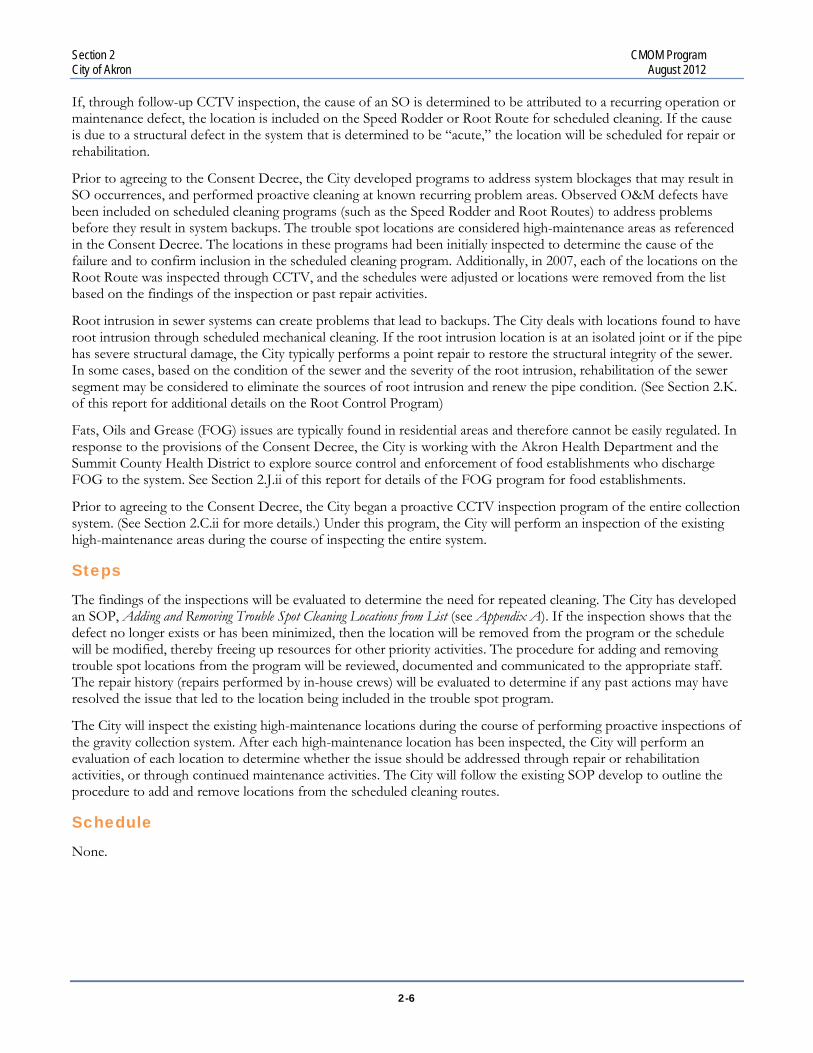
The City is continually exploring increased staffing levels and the use of alternative inspection technologies to facilitate meeting the 2014 date. The City has evaluated the use of automated sewer inspection equipment and techniques that can be deployed with minimal crew interaction. Four of the Redzone SOLO units have been purchased by the City. This technology will be deployed in areas that are predominately served by 8-inch to 12-inch sewers. Additionally, the City has begun exploring available technologies for inspection of large-diameter sewers (e.g., greater than or equal to 36-inches diameter). The City has acquired information from various vendors and peer communities to determine the most appropriate technique and approach to perform these inspections.
As stated above, the City is currently inspecting the area tributary to Mud Run Pump Station in a systematic approach. The preliminary plan for the proactive inspection program includes continuing to schedule the activities geographically for each of the fourteen defined districts. Within each district, the inspections will be assigned on a mini-district basis to systematically complete each main district. The order in which areas are assigned may be driven by upcoming capital improvement projects or in support of other consent decree related projects. Additionally, the deployment of automated inspection equipment will be utilized where maximum production levels can be achieved.
For the remainder of 2010, the focus will continue to be on mini-district inspections. In 2011, while performing mini-district inspections by in-house staff, the City incorporated inspection of the large diameter sewers, under outside contract, into the program. The City will continue to schedule and track the inspection activities to meet the cumulative annual average of 20 percent of the system for years 2012, 2013 and 2014. Regular meetings are held to assess progress. A dashboard tracking tool is being developed to track production on a daily basis.
Steps
None.
CCTV inspection leading up to at least 20% of all gravity sewer pipe each year, starting with 10% in Year 1, 15% in Year 2, and 20% in subsequent years, with CCTV inspection of all gravity sewer pipe in the Sewer System, which shall include CCTV’ing performed by Akron during calendar year 2008 through the date of U.S. EPA approval of the Collection System CMOM Program, not later than December 31, 2014; 2.C.ii
Redzone’s Solo is one example of
autonomous sewer inspection equipment.

Section 2 CMOM Program City of Akron August 2012
2-8
Schedule
The City will continually track inspection activities to determine if the program is on target to achieve the 2014 inspection deadline. If it is observed during monthly or annual reviews that production falls behind projected estimates to achieve compliance by 2014, additional resources, revised schedules or new technologies will be used to achieve the 2014 inspection deadline. It is also possible that the City will exceed the annual percent inspection requirement. Any inspections completed in a given year above the annual percent inspection requirement shall be credited toward the City’s goal for the following year.
Status
The City owns and maintains 19,508 manholes as part of the sanitary and combined gravity sewer system. The City inspects manholes as part of normal field activities by a variety of Sewer Maintenance and Engineering Bureau staff members. In anticipation of the requirements of the Consent Decree, the City’s staff members have begun to proactively inspect manholes in advance of the area cleaning and inspection program. A significant number of staff members have been trained in performing visual inspections of manholes and in how to complete the inspection form.
The City’s plan is to perform a comprehensive and detailed inspection of each gravity system manhole during the first five-year cycle to obtain attribute data, and to identify any structural defects that may reduce the useful life of the structure and/or allow Inflow and Infiltration (I/I) into the system or will otherwise need to be addressed through repair activities. If a manhole defect is allowing excessive I&I into the system, that manhole is identified for manhole sealing. Manholes that require sealing will be included in the capital improvement plan.
Since many manholes are located in high traffic areas, those inspections are difficult to perform without significant resources to allow for safe access to the structure. Therefore, the City is exploring the use of automated sewer inspection equipment and techniques for pipes and may be able to perform manhole inspections as well.
Manhole inspection data is logged either on hardcopy inspection forms or by using mobile GIS software to capture the same information digitally (see Appendix B for a copy of the manhole inspection form). The inspection data is stored electronically, the work performed is tracked in the maintenance management system, and manholes that have been inspected are displayed in the GIS mapping system. Additionally, the number of manholes inspected is tracked on the Semi-Annual Reporting Tracking Sheet, which is used to generate the reports to USEPA due in February and August of each year.
Steps
None.
Schedule
The City will continue to conduct and track manhole inspections at an average rate of approximately 4,000 manholes per year, including inspections performed in 2008 and 2009, to reach compliance with this Consent Decree element of inspecting all manholes by December 31, 2014.
If it is observed during monthly or annual reviews that production falls behind projected estimates to achieve compliance by 2014, additional resources, revised schedules or new technologies will be used to achieve the 2014 manhole inspection deadline.
Inspection of all manholes in the Sewer System every five (5) years, which shall include manhole inspections performed by Akron during calendar year 2008 through the date of U.S. EPA approval of the Collection System CMOM Program, not later than December 31, 2014; 2.C.iii
Section 2 CMOM Program City of Akron August 2012
2-9
After December 31, 2014, the City will streamline the visual inspection procedures to identify only structural deficiencies that will need to be addressed.
i. Defects that materially threaten the structural integrity of the pipe or structure;
ii. Defects that allow infiltration, inflow, or exfiltration;
iii. Pipe defects, including but not limited to, cracks, holes, corrosion, misaligned joints, root intrusion, sags, improper lateral taps, or other defects that make the pipe or structure prone to grease, root, or debris blockages;
iv. A rank or score of the condition of each inspected pipe or structure on a sliding scale that indicates the severity of any defects found;
v. Whether the pipe or structure requires either short or long-term repair;
vi. Changes to cleaning frequency as a result of the assessment; and
vii. An estimate of the expected remaining service life of the pipe or structure.
Status
The City will continue to document locations that allow I/I into the system or exhibit exfiltration during CCTV and manhole inspection through the codes available in the PACP inspection software. If the City concludes that I/I is causing a problem within the system, the inspection data will be evaluated to determine the highest priority areas and develop a plan to address the sources of I/I. Locations with observed O&M defects have been included on scheduled cleaning programs such as the Speed Rodder or Root Routes to address problems before they result in a back up in the system. These locations are considered high maintenance areas and have been included in the program based on past inspection information.
Poor construction will be identified through the condition assessment program.
Long-term rehabilitation and replacement projects are included in the five-year capital budget for future contract development.
The City has been using CCTV inspection software for many years, and the PACP module of the software was installed in late 2009 to facilitate objective assessment and consistent coding of structural and O&M defects in the system. In addition to training the current Telemonitoring Technicians, the City trained 20 other staff members on the PACP coding system. The PACP coding provides a numerical rating system that can be used to help rank or prioritize defects that are determined to be acute. The PACP rating system (with a scale of 1 to 5 where 5 indicates a severe defect) has been recognized around the country as a universal approach to categorize defects and help determine whether a defect requires long-term, short-term or immediate attention. The City has adopted this rating system and will apply it to the decision making process for defect remediation and the determination of what defects are considered acute.
The City has been studying industry information about estimating remaining service life of pipes based on a variety of attributes and condition ratings. The condition rating system in PACP provides guidance on the remaining useful life (RUL) of a pipe segment based on observed defects and City will utilize this feature to determine the remaining useful life of its pipes. The City will use the PACP rating system to provide information to rank one location relative to another based on risk factors, and to determine if a repair or additional inspection is needed in the short-term or long-term.
To assist in tracking the information needed for Semi-annual Report requirements, the City has developed a formal process to track when the problem was found, if a defect is determined to be acute, and when the repairs were made.
Preparation of condition assessment reports following CCTV inspections that, at a minimum, document the following:
2.C.iv
Section 2 CMOM Program City of Akron August 2012
2-10
The locations will be linked to GIS to provide a visual representation of the locations. (See Appendix E for the tracking template.)
Steps
Regarding long-term rehabilitation or replacement projects completed under contract, as well as maintenance activities completed under contract, the City has refined the documentation and reporting process. The City will include contract repairs, cleaning or inspection with the activities performed by in-house crews to generate a comprehensive report on improvements to the system.
As stated under 2.C.ii. above, through the course of performing proactive system inspection, the locations associated with high maintenance areas will be assessed to verify if the cause still exists, or if structural issues (such as sags) are contributing to O&M issues. If the cause no longer exists, or if a repair is identified and performed, the City will adjust the cleaning frequency, thereby freeing up resources to perform other proactive tasks. Any adjustments to the cleaning frequency due to the findings of these inspections will be documented for future reporting to the EPA.
The NASSCO estimation of remaining useful life (RUL) is to be used as guidance in providing relative prioritization of rehabilitation and replacement activities. Several inspections may be required to determine if a defect is unstable (getting worse based on increasing PACP severity) rather than relying only on what is observed from any single inspection. Therefore, the City will deploy a computerized tool to process additional condition factors and risk attributes, in addition to observed PACP defects to calculate the estimated remaining useful life of the pipes. The tool selected is a decision model, non-proprietary, GIS-based asset management program that will be used to evaluate inspection data and prioritize repairs, rehabilitation, and replacement work.
Schedule
The formal process to track the identification and remediation of structural defects will be continually assessed to identify improvements in how the data is collected and managed.
Status
Historically the City of Akron has cleaned gravity pipes as a part of the CCTV program, as a part of the trouble spot program, and in response to complaints. The trouble spot locations are cleaned either every 6 months or yearly, depending on the cleaning requirements of each specific location.
The City will continually track cleaning activities to determine if the program is on target to achieve the 2014 cleaning target. If production falls behind, additional resources or new technologies may be used to reach the goal. It is also possible that the City will exceed the annual percent cleaning requirement. Any cleaning completed in a given year above the annual percent cleaning requirement shall be credited toward the City’s goal for the following year.
Complete one (1) cleaning of each gravity sewer pipe in the City’s Sewer System by December 31, 2014, which shall include gravity sewer line cleaning performed by Akron during calendar year, 2008; 2.D.i
2.D.
Cleaning gravity sewer lines as necessary Additionally, Akron shall:

Section 2 CMOM Program City of Akron August 2012
2-11
Steps
To comply with this element the City is determining the footage cleaned in 2008 and 2009 so that credit can be received for the pre-2015 cleaning. A review of the work orders and the GIS database should provide a close estimate of the footage.
This program is being conducted in parallel with the CCTV program (see Section 2.C), but may include some cleaning in addition to the cleaning associated with the CCTV program and with the trouble spot program.
In some cases, sewers have undergone CCTV inspection prior to cleaning. If a CCTV Inspection confirms that the sewer is clean, meeting NASSCO standards of 95% of original carrying capacity, then that sewer segment shall be considered cleaned for the 5 year cleaning cycle.
The City is performing an aggressive CCTV program to meet Consent Decree requirements. That program will compare the quality and quantity of completed CCTV inspections with and without prior cleaning. Results of that comparison will influence the gravity system-cleaning program. Other considerations for developing an on-going systematic cleaning program will include the factors listed below: Pipe criticality (likelihood and consequence of failure) Resource needs Cleaning methodologies CCTV program Pipe slope Amount and type of debris removed Geographic location Sewer basin
As a part of developing the gravity-system cleaning program, in 2012, the City will begin collecting data that will help them modify sewer system cleaning frequencies. Examples of data to be collected are the amount of debris (light, medium or heavy, number of cleaning passes performed, cleaning tools used, and the type of debris (sand, rocks, paper products etc.). The decision model is currently being developed and will be used for preparing the post 2014 cleaning and inspection program.
Schedule
The cleaning program is being conducted in parallel with the CCTV program and will follow that schedule.
No further action is required.
Status
There is no current program to clean the gravity sewer pipes beyond 2014, other than cleaning associated with complaint response, CCTV and trouble spot cleaning.
Continue with ongoing cleaning of each gravity sewer pipe in the City’s Sewer System on a minimum five (5) year frequency; 2.D.ii
Section 2 CMOM Program City of Akron August 2012
2-12
Steps
After the pre-2015 program is developed and implemented a post-2014 cleaning program can be developed. The Consent Decree clearly requires the entire system be cleaned on a 5-year basis beginning in 2015. One way to accomplish this requirement is to develop a sewer-basin approach or a geographic approach to cleaning and rotate through the system on the required 5-year interval. However, such an approach could result in cleaning some pipes that may not need cleaning and cleaning other pipes less frequently than needed.
A cleaning program based entirely on a calendar interval will meet requirements of the Consent Decree. However, that type of a program may not best meet the intent of the Consent Decree or of the USEPA’s proposed CMOM rule. The City understands that the goal of both the consent decree and CMOM is to reduce and minimize the number of sewer overflows. It is also believed that effective CMOM Programs achieve these goals by applying principles of asset management1
In the case of cleaning programs, the goal of minimizing sewer overflows is achieved by cleaning the pipe to maintain needed capacity. Calendar based programs often tie up valuable resources cleaning pipes that may not need cleaning (pipes that have adequate capacity) while under-cleaning others parts of the collection system (pipes that have reduced capacity from debris). It is further realized that keeping all pipes free of all debris is not possible; pipes with flat slopes are prone to collecting debris thereby reducing capacity.
. Sewer blockages will sometimes occur due to factors outside of the City’s control. There is no way to predict or prevent all blockages from occurring.
The City will develop a long-term systematic cleaning program that is based on condition that can be established from the CCTV inspection reports and information obtained as a part of the first cleaning of the entire Akron collection system. Capacity needs and history sewer overflows will also be considered when determining cleaning frequencies.
Schedule
Begin developing the post-2014 cleaning program in 2012 with a review of CCTV and cleaning data that has been obtained through 2011. As additional CCTV and cleaning data is obtained through the end of 2014, the post-2014 cleaning program will be refined. The decision model is currently being developed and will be used for preparing the post 2014 cleaning and inspection program. A more detailed schedule will be included as a part of future Semi-annual Reports after the initial data review.
Status
Pump Stations
Currently the City responds to pump station alarms daily. The pump station alarms are monitored through a SCADA system and crews are dispatched to the pump station in accordance with alarm responses defined and kept in the SCADA system. Depending on the nature of the alarm, the responding crew will either correct the situation, or prepare a work order to have the problem resolved.
1 Asset management is a structured program to deliver the service levels the customers require while minimizing the whole-life costs of asset ownership.
2.E.
Routine annual preventative maintenance of Pumping Stations and Force Mains;
Section 2 CMOM Program City of Akron August 2012
2-13
Routine pump station checks are performed on a weekly basis. As a part of the weekly visits the crew runs all pumps and the generator, cleans the bar screen, and records pump hours. Scheduled maintenance activities, such as oil changes and lubrication of rotation equipment, are conducted at the regular recommended intervals. A log of the station visits is kept at each station and work is recorded in the CMMS.
The City has developed SOPs pertaining to the maintenance of pump stations. The SOPs are located in Appendix A of this report.
Force Mains
The City monitors pump performance as an indicator of force main condition. The only known problem force main was at the Brookshire pump station. The City rebuilt the Brookshire pump station and found that the new pumps had trouble keeping up with the flow because the 8-inch force main had tuberculation that effectively reduced the diameter by approximately 50 percent. The City replaced the force main in August 2006.
A basic form of force main maintenance is to verify the operation of air valves and to routinely exercise force main isolation valves. The City’s SOPs for force main valve maintenance are included in Appendix A.
Steps
No steps are needed.
Schedule
The current pump station maintenance program satisfies the requirements of the Consent Decree, therefore no schedule is needed.
Status
There is currently no program specifically for sealing manholes.
Steps
The manhole-sealing program required by the Consent Decree will be a part of the manhole condition assessment and the Rehabilitation/Replacement (R&R) program for the gravity sewer system. Generally, when conditions are found that warrant the sealing of a manhole, such as excessive inflow or infiltration based on engineering judgment, the manhole will be sealed. Typically, the most appropriate, cost effective technology and technique for a given situation will be used to address manholes in specific sub-basins with higher levels of I/I, relative to the other sub-basins. Technologies considered will include cementitious material for lining manholes or sealing of acute leaks, or cured in place or spray-on materials.
Schedule
Determined with the implementation of the gravity system R&R program, described in Section 2.I.ii and 2.I.iii.
2.F.
Sealing (where appropriate) and maintenance of manholes;
Section 2 CMOM Program City of Akron August 2012
2-14
Status
There is currently no stand-alone program for identifying and remediating poor construction.
Steps
Identifying and remediating defects caused by poor construction will become a part of the condition assessment and R&R programs (see sections 2.C.iv, 2.H and 2.I). Generally, when defects are determined to be caused by poor construction techniques, construction inspection personnel will be notified in an effort to reduce or eliminate similar problems on future construction projects.
Schedule
Developed as a part of the condition assessment and R&R programs, described in section 2.I.ii and2.I.iii.
Status
The City uses a design manual, design guides and construction material specification (ACMS 2008 edition) with associated standard drawings for the construction of sewers (See Appendix B for current sewer specifications). Standard specifications include testing prior to acceptance. The manual is updated on an as-needed basis. Over the past ten years, this manual has been updated three times; in 2002, 2004 and 2008.
All sewer construction connecting to the Akron collection system is required to adhere to Akron’s standards for the design and construction of sewers. Sewers that are connected to the City’s system are inspected by Sewer Maintenance personnel or by the Akron Engineering Bureau personnel via a CIP project to help assure that they were installed in accordance with the City’s requirements.
Design engineers are required to demonstrate that there is enough capacity in the collection and treatment system prior to allowing a new connection. The engineer of record is required to stamp the construction drawings, which demonstrates that sufficient capacity exists for the new connections.
Currently, construction plans are to include notes prohibiting storm water connections to the sanitary sewer system. Sections 50.15 and 50.46 of the City’s Sewer Ordinance prohibit storm water connections to sanitary sewers. The plans for sewers and system connections are reviewed and approved prior to construction by Akron Engineering Bureau, Akron Sewer Bureau, or Plans and Permits Division. These sewers are then inspected as they are constructed to verify that the work was performed in accordance with the plans and specifications.
Steps No steps are needed as procedures are currently in place.
2.G.
Identification and remediation of poor construction;
Procedures for ensuring that new sewers and connections are properly designed and constructed (including testing of new sewer installations) to prevent overflows and to ensure that new connections of inflow sources are prohibited; 2.H.

Section 2 CMOM Program City of Akron August 2012
2-15
Schedule
No schedule is needed.
Status
The City of Akron’s current practice is to correct significant defects when they are discovered. When a defect is found, a work order is prepared to correct the defect. Repair records can be found in the CMMS. There is an SOP in Appendix A that describes how the City enters a work order into the CMMS; the CMMS Datastream Users Guide is found in Appendix D.
Documenting and implementing a defined process to identify and correct acute defects is described in 2.C.iv. This will be a part of the condition assessment and R&R processes, and include special tracking and reporting of “acute” defects. The process will include documenting the asset ID, date discovered, estimated schedule, and the proposed and the actual repair completion. Section 2.C.iv of this report describes a template for tracking acute defects.
Steps
No steps are needed as procedures are currently in place.
Schedule
No schedule is needed.
A schedule to address defective pipes that is based on the results of the condition assessment required under Paragraph 2 (B) and a schedule under which Akron shall replace, rehabilitate, or permanently repair any other pipes necessary to reduce the risks of SSOs and CSS Releases and ensure the long-term sustainable renewal of the City’s infrastructure. Permanent repair means the correction of a structural defect in a manhole-to-manhole pipe segment such that the repair has the same life expectancy as a rehabilitated pipe; 2.I.ii
Repair of all acute defects (i.e., those defects that have caused or substantially increase the probability of an SSO or CSS Release, including conditions leading to imminent structural collapse or that would create repeated blockages) within one (1) year of discovery of the defect. Akron shall maintain a log listing all sewer line acute defects in need of expeditious repair or replacement, the date the City discovered the acute defect, an estimated schedule for performing the repair or replacement, and the date of project completion;
2.I.
Procedures for ensuring that repair, rehabilitation and replacement projects are properly designed and constructed (including testing of rehabilitation installations) to prevent overflows, including;
2.I.i
Section 2 CMOM Program City of Akron August 2012
2-16
Status
Currently, the City bases R&R projects on condition assessment information. Defects requiring immediate correction are done by creating a work order and scheduling of internal staff or by contracting outside services. Based on the severity of the defect and the capability of City resources, the City may declare an emergency to correct problems.
In addition to correcting defects that require immediate attention, the City annually updates a 5-year CIP to include projects for the collection system that are based on findings of the condition assessment program. Staff members meet at the beginning of the fiscal year to prioritize improvement projects that the O&M staff members have identified. After the list of projects is prioritized, projects that fall within available budget move forward. Projects that do not get funded are delayed and are considered for funding the following year.
Steps
A program to address defective pipes is in place and the schedule is found in the CIP.
Schedule
No schedule is needed.
Status
The City currently tracks pipe and structure repairs performed by City crews using work orders in the CMMS. Repairs performed during 2008 and 2009 were manually digitized in the GIS as points showing the location of the repair, attributed with the date and work order number under which the repair was made.
Repairs performed by contractors are documented in contract drawings.
The City has begun maintaining a summary spreadsheet to keep track of all pipe and structure-related projects, including the following information: Project name (work performed by contractors)/ work order number (work performed by City) Contractor/City Start date Completion date IDs of assets affected Summary description of repair performed per asset
The information for work performed by City staff will be queried from the CMMS by selecting records coded using specific repair work order codes. The information for projects completed by contractors will be captured by City of Akron Engineering Bureau and Akron Sewer Bureau staff when inspecting sewer installations and connections.
The Update Project Tracking Log SOP is included in Appendix A, and the template spreadsheet Project Tracking Log is included in Appendix B.
Steps
No steps are required.
Maintenance of a log listing each sewer pipe and structure project completed during the previous year and the date the project was completed; 2.I.iii

Section 2 CMOM Program City of Akron August 2012
2-17
Schedule
The project-tracking log will be updated with CMMS summary data on an on-going basis and with contractor-performed project data as the work is inspected.
Status
Fats, Oils and Grease (FOG) are detrimental to the proper operation of wastewater collection and treatment systems. Grease is a major cause of sewer line blockages and causes operational problems in wet wells, pumps, air relief valves and other collection system equipment and structures. Oils and grease can also be harmful to aquatic life, if entering via a SO or passed through the treatment plant.
According to the City of Akron, Municipal Code Chapter 50, Sewers, §50.46 General discharge prohibitions
C. Any substance which may solidify or become viscous at temperatures between 32°F and 149°F (0°C and 65°C).
, paragraphs C through F include the following:
D. Petroleum oil, non-biodegradable cutting oil or products of mineral oil origin if discharged in amounts that can pass through or cause interference of the POTW.
E. Wastewater from industrial facilities containing floatable fats, wax, grease, or oils.
F. Wax, grease or oil concentration of animal or vegetable origin exceeding 100 milligrams per liter whether emulsified or not. Wax, grease, or oil concentration of mineral origin exceeding 50 milligrams per liter whether emulsified or not.
Enforcement of this ordinance is vital to limiting the impact of FOG discharges in the sewer system.
The City maintains a list of pipe segments that, due to FOG, have been subject to sewer blockages or backups. The list contains locations of mainline blockages resulting from residential and commercial sources of FOG. Each of the segments has been entered into the CMMS and a work order is issued every 6 or 12 months, based on severity, to conduct preventative maintenance cleaning of the designated segment. Work Orders are issued and completed based on geographic location in order to expedite the inspection and cleaning process.
Procedures to identify and mitigate backups are included in the SOP Sewer Blockage Investigation (Check Main Sewer). The SOP Proper Manhole Inspection also provides guidance for inspecting manholes for the presence or discharge of FOG into the sewer system.
An SOP has been developed to maintain the FOG trouble spot list. This SOP describes the procedures for adding or removing a sewer section to the FOG trouble spot list, categorizing and prioritizing segments for periodic cleaning,
Procedures for identifying and mitigating fats, oil, and grease (FOG) trouble spots throughout the collection system. Akron shall prepare and maintain a list of FOG trouble spots in the collection system, identifying the specific pipe segments where FOG trouble spots are found. This list shall include an accelerated inspection and cleaning program for these trouble spots. Akron shall develop a methodology to categorize and prioritize the FOG trouble spots and develop inspection and cleaning schedules for these trouble spots. Akron shall use this methodology to update annually its list of FOG trouble spots, including the inspection and cleaning schedules. 2.J.i
2.J.
A grease control program that, at a minimum, includes the following:
Section 2 CMOM Program City of Akron August 2012
2-18
and annually updating the list (see SOP in Appendix A, Fats Oils Grease (FOG) Trouble Spot Investigation and Speed Rodder List Maintenance).
Steps
The City has documented procedures for maintaining a FOG trouble spot list as described above and no further actions beyond current procedures are required at this time.
Schedule
None.
Status
Inspection of Food Service Establishments (FSEs) is the responsibility of the Summit County Combined General Health District (Health District). FOG control device installation and regulation are duties reserved for the Summit County/Akron Building Department via the State Building Code. Coordination of efforts among these departments and Sewer Maintenance will aid in limiting the discharge of FOG from FSEs in the Akron Sewer System.
On December 29, 2011, a Supplemental Protocol was executed between the City and the Health District. This Supplemental Protocol established procedures for coordination of responsibilities between Sewer Maintenance and the Health District. However, when the City of Akron Sewer Maintenance staff responds to a sewer back-up complaint, potentially caused by a FSE, the Health District is notified and an inspector is assigned to investigate. An SOP has been developed to outline these steps. (See Health District Notification SOP in Appendix A)
There are currently no documented procedures for inspections and follow-up actions for FSEs. FSEs are not required to keep records pertaining to the FOG control devices.
Therefore, additional FOG requirements are being added to the City’s existing Sewer Use Ordinance for passage by City Council.
Steps
• Dates of grease removal;
Require FSEs to maintain, on site, records of grease control device maintenance including the following information:
• Amount of grease removed;
Procedures for coordinating with the Akron Health Department and the Summit County Health Department to conduct inspections and take follow-up actions for FOG trouble spots that are determined to be caused by Food Establishments. When trouble spots are identified to be caused by a Food Establishment, Akron shall follow these procedures to ensure that the Food Establishment installs proper FOG control devices to prevent excess FOG discharges to the Sewer System. For these Food Establishments, Akron shall also ensure onsite record keeping at the Establishments, including but not limited records of the dates of grease removal, the amount of grease removed, and the location where the Food Establishment disposed of the grease and the name, address, and phone number of the hauling or recycling service used to transport the grease. Akron shall maintain a list of all Food Establishments determined to be the cause of FOG trouble spots and the specific actions taken to ensure that those Food Establishments install proper FOG control devices. 2.J.ii

Section 2 CMOM Program City of Akron August 2012
2-19
• Location where the FSE disposed of the grease; and • Name, address, and phone number of the hauling or recycling service used to transport the grease.
A copy of the revised Sewer Use Ordinance will be available when passed by council and will be included in the subsequent Semi-Annual Report.
Schedule
A copy of the executed Supplemental Protocol has been provided in the August 14, 2012 Semi-Annual Report.
COMPLETE - Establish coordination procedures with the Akron and/or Summit County Health Departments. This task shall be completed no more than 365 days following the contract for coordination of services between the Akron and Summit County Health Departments.
COMPLETE - Establish requirements for FSEs to maintain, on-site, records of grease control device maintenance. A meeting between the City of Akron Sewer Maintenance Division and the Health District shall be held within 120 days following the contract for coordination of services, between the Akron and Summit County Health Departments, to discuss requirements and possible Ordinance revisions necessary and other FOG program coordination issues.
COMPLETE - Develop an SOP to formalize and document notification and inspection procedures between the City and the Health District. This task shall be completed no more than 365 days following the contract for coordination of services between the
Akron and Summit County Health Departments.
Status
Providing public education and educating the Food Service Establishments (FSEs) on matters relating to the proper disposal of FOG is necessary to reduce FOG discharged into the sewer system. Coordinated efforts between the Health District and the Sewer Maintenance Division will be required. Educational materials should address the following: Proper FOG control device installation and maintenance; FOG control device maintenance record-keeping; Proper food waste disposal; and Response to an accidental FOG spill/release.
The Sewer Maintenance Division currently sends annual notices, via bill stuffers, to all customers informing them of prohibited discharges. The City Maintenance Division also attends public meetings on an as-invited basis and provides handouts. See Bill Stuffer and Public Meeting Handout in Appendix B.
Steps Update bill stuffers to send to all customers with additional information regarding proper FOG disposal.
Educational efforts aimed at FOG sources and, if appropriate, residential users, and recommendations for changes to public education, outreach and compliance efforts to inform commercial, institutional and residential property owners and tenants about the need to minimize the introduction of grease into the Sewer System.
Provide educational material regarding FOG disposal and control device maintenance on the City of Akron website.
2.J.iii

Section 2 CMOM Program City of Akron August 2012
2-20
Provide educational material to Health District regarding FOG disposal and control device maintenance.
Schedule
Provide copies to Health District for distribution to FSEs and other institutions (schools, hospitals, nursing homes, etc.) during inspections.
The educational material steps described above will be impacted by the merger of the health departments. Therefore, the educational material steps will be completed no more than 365 days following the contract for coordination of services, between
Akron and the Health District.
Status
Known root problem areas are included in the trouble spot / Speed Rodder list (see Section 2.C) and are cleaned on a routine interval in an effort to prevent overflows that may result from the intrusion of roots into the sewer. The root cleaning is scheduled. Work orders to remove roots may be found in the CMMS system.
In 2007, the City televised all locations on the root list. The city adjusted the cleaning frequency, made spot repairs and updated the list based on results of the CCTV investigation. The City will continue to update the root list and root cleaning frequencies base on information obtained as part of the ongoing CCTV program described in Section 2.C of this report.
Root problem areas that are more extensive are placed on the R&R list for consideration as a capital project. If an improvement project removes the root intrusion problem the area is removed from the Speed Rodder list.
The city tried in-house chemical root cleaning and contracted chemical root cleaning but found mechanical root control to be more effective.
The root control inspection program is included as a part of the gravity system condition assessment program.
Steps
The City has processes and procedures in place for a root control program. No further action is required at this time.
Schedule
None.
2.K.
A root control program that addresses, at a minimum, scheduling and performing corrective measures including both short-term mitigation of root intrusion (i.e., routine maintenance) and rehabilitation of the areas in which root intrusion has caused recurring blockages (i.e., sewer replacement or relining), and a proposal that includes scheduled inspection of known problem areas;

Section 2 CMOM Program City of Akron August 2012
2-21
Status Complaints:
The City has a process in place for receiving complaints, issuing investigative/corrective work orders, and documenting the results using the CMMS. The Documenting Complaints SOP is included in Appendix A and makes reference to the APUB CFO Datastream 7i Extended Training Guide included in Appendix D. Work orders:
• Reactive Maintenance
The City uses the CMMS to issue and track work orders for preventative, reactive, and planned maintenance work. The Creating and Completing Blank Maintenance Work Orders SOP included in Appendix A outlines the process for issuing and tracking work orders for the following work types:
• Sewer Planned Maintenance • APUB Additional Work Required • Preventative Maintenance
The workflow diagrams for these work types and detailed instructions for using Datastream are outlined in the “Work Management” and “Materials Management” and “APUB Workflows” sections of the “APUB CFO Datastream 7i Extended Training Guide” included in Appendix D.
Equipment inventory:
The City has processes in place for logging equipment inventory changes into the CMMS, including initial purchase, issuing and returning parts, tracking storeroom transactions, and completing a physical inventory. These processes are discussed in Section 2.A of this document. Sewer system components:
The City has processes in place for documenting changes to sewer system components in the GIS and synchronizing those changes with the CMMS as discussed in section 2.A of this document. The procedures for updating the GIS discussed in that section are outlined in the “APUB GIS Standards and Procedures” document included as Appendix C. The procedures for synchronizing newly created assets in the GIS with the asset inventory in Datastream 7i are outlined in section 9 of the “APUB GIS Standards and Procedures” document and in the “APUB Datastream 7i GIS User's Guide” included in Appendix D. Scheduling and tracking of maintenance:
•
The procedures used to schedule and track maintenance activities in the CMMS are outlined in the “APUB CFO Datastream 7i Extended Training Guide” included in Appendix D. The “APUB CFO Datastream 7i Extended Configuration Document” included in Appendix D describes the processes for configuring and administering the CMMS, including defining:
• Asset classes
• Work Order types
• Work Order classes
• Status types
• Change Status types
Users/Functions
2.L.
Description of a method for documenting complaints, work orders, updates to equipment inventory, and changes to Sewer System components, as well as entry of such data into a data management system that allows ready use of the information including the capability of scheduling and tracking both preventative and reactive maintenance activities;
Section 2 CMOM Program City of Akron August 2012
2-22
Steps No steps required.
Schedule
Continue scheduling and tracking maintenance activities as part of on-going efforts.
Status
Corrective maintenance performed by City crews is currently logged in the CMMS via work orders. Each work order is associated with one primary asset, but can have other assets manually associated with it in the CMMS work order record. Work orders are used to track corrective maintenance performed, location, and the crews involved. The procedures for scheduling, performing and reviewing corrective maintenance activities using the CMMS are documented in the “Reactive Maintenance Workflow” using the processes outlined in the “Work Management” section of the “APUB CFO Datastream 7i Extended Training Guide” included in Appendix D.
Steps No steps required.
Schedule
Continue tracking and reporting on corrective maintenance activities as part of on-going efforts.
Status
The intention of this Consent Decree requirement is to assure that City staff members are adequately trained and provided the required equipment to minimize the effects of SSOs and CSSRs. Additionally PACP training will assist in providing consistent information in support of Consent Decree element 2.C.iii.
The City continually provides a variety of job-related training, safety procedures, and equipment to enable the staff to perform their daily duties and to address problems in the sewer system. To do this the City has identified several ways to help their staff perform their jobs more effectively. The City has developed a number of SOPs to provide instruction and to define consistent procedures in order to train the staff. Another method to train staff for specialized activities within Sewer Maintenance is through On-the-Job Training, where experienced staff members
2.N.
Adequate training of staff and adequate equipment to ensure that Akron promptly identifies and addresses problems in its Sewer System that lead to SSOs and CSS Releases. Within two (2) Years following the Date of Lodging of this Consent Decree, Akron shall ensure that at least one member of each CCTV crew has attained Pipe Assessment Certification Program (PACP) certification;
2.M.
Corrective maintenance response and reporting procedures;

Section 2 CMOM Program City of Akron August 2012
2-23
provide less experienced employees with details on how to perform their unique job duties. Some staff members hired for skilled positions, such as electricians, are considered based on their experience and previous training obtained outside of city employment.
A number of staff members have been provided training on the CMMS and in the use of GIS mapping.
The City has begun the use of PACP certified inspection software in the CCTV trucks. The three current Telemonitoring Technicians have been trained and certified in the use of PACP coding. Additional employees, who review the CCTV inspection reports and use the inspection data, have been trained and are in the process of obtaining certification.
The City completed and submitted the SORNP to the EPA on February 11, 2010 for review and comment. This plan and the associated tracking of sewer overflows will assist in facilitating follow-up inspection activities to identify and mitigate the causes of the sewer overflows.
The City has developed a number of SOPs to document the steps needed to perform various tasks conducted by the Sewer Maintenance staff. SOPs also provide information to assist in training newer staff members.
Steps
Once the SORNP is approved by the EPA, the City will provide training on the plan to staff that are responsible for responding to reports of sewer overflows.
Schedule
Train applicable staff (those who may respond to a report of a sewer overflow) on the SORNP, within 60 days of approval of the SORNP from the EPA. Additionally, the staff will be trained on the Consent Decree requirements to better understand their roles in meeting compliance.
Train and certify new Telemonitoring Technicians, prior to performing any CCTV inspections in the field that require PACP certification.
Status
Root Cause Analyses (RCAs) proactively seek the fundamental causes that lead to failure. The goals of an analysis are to find the cause of a problem efficiently and economically; correct the cause of the problem, not just its effect; and provide information that can help prevent the problem from recurring.
Currently the City of Akron investigates SSOs and CSS releases to determine the cause of the event. At this time, a documented approach to determine the root cause for situations in which the City’s sewer system failed to perform as designed or resulted in an SSO or CSS release is a part of the SORNP.
2.O.
Description of a “root cause analysis” process for situations in which the City’s Sewer System failed to perform as designed or resulted in an SSO or CSS Release. This process shall include the documentation of all the known operational variables that lead to the failure in performance of the Sewer System or the SSO or CSS Release event;
Section 2 CMOM Program City of Akron August 2012
2-24
Steps
The City will further develop a process to conduct structured investigations that aim to identify the true cause of a problem and the actions necessary to correct the cause of the problem. The process will include all known operational variables that lead to the SSO or CSS release. The RCA process was defined by the City in a new regulatory SOP, “Root Cause Analysis Process”. Basic components of the process include the following: Assembling a team to perform the RCA;
o For typical maintenance-caused failure, the RCA team consists of the Sewer Maintenance Division Staff
o For structural and operational failures, the RCA team includes members of the Sewer Maintenance Division and the Akron Engineering Bureau’s Environmental and Construction Divisions.
Determining the nature of the problem and collecting data necessary to determine the cause; Analyzing the collected data to identify the root cause; and Seeking to eliminate the root cause of the problem through implementation of a solution.
Schedule
Initiate defining a Root Cause Analysis procedure within 180 days of approval of the CMOM Program by the USEPA and the Ohio EPA. The Root Cause Analysis procedures will be defined in the SOP, “Root Cause Analysis Process” and submitted to EPA in the subsequent semi-annual report.
Status
O&M manuals are used as a reference sources for the operators of a given system. A current, understandable and practical O&M manual is a valuable tool for training new employees and providing long-term guidance in standard operation and maintenance procedures to existing operations staff.
Several documents or collections of documents maintained by the Sewer Maintenance Department contain much of the information assembled in a typical O&M manual. Three of the documents are described below.
O&M Manual for Combined Sewers
The City has an O&M manual for the Combined Sewer System. The City originally submitted this document in August 1994 and last updated it March 5, 1998. It i
Section I Introduction
ncludes rack information and drawings of each of the racks, along with the following six sections:
Section II The Collection System Section III The Wastewater Treatment Plant Section IV Previous Studies and Ongoing Combined Sewer System Work Section V Identification of System Problems Section VI Current Operation and Maintenance Practices with Regard to the Nine Minimum Controls
2.P.
An annual update of the operation and maintenance manuals.
Section 2 CMOM Program City of Akron August 2012
2-25
Sewer Pump Station Notebook
The notebook contains various documents associated with the pumping stations. It includes design data, manufacturer information, electrical system voltage, physical dimensions, pump type, motor horsepower, stand-by power type, length of force main, and force main location maps. Rack location drawings, underground map references, depth and location of centerline of manhole relative to the rack are also contained in the notebook (Appendix B includes examples of rack and pump station sections).
The Pump Station Notebook is updated on an as-needed basis.
Standard Operating Procedures Manual and Checklists
The Sewer Maintenance Division has written SOPs for various tasks. These documents are categorized into the following groups: Administrative Sewer Laterals Overtime Regulatory Work Order Database Safety Maintenance Inventory
Dispatcher Datastream 7i Extended
Timesheets Pump Stations
Payroll OSHA Regulations
The City also has several O&M task checklists for main sewer, confined space entry, manhole inspection, pump station, and vehicle pre- and post-trip inspection. Equipment checklists are used for Flex Rodder, maintenance van, Speed Rodder, utility van, and Vac-Con.
Appendix A contains the Sewer Maintenance Division SOPs and Appendix B includes examples of the multiple forms, checklists and other documents utilized by the Sewer Maintenance department for recording operational and maintenance information, providing training to employees, budgeting and other purposes.
Sewer Maintenance staff create and update SOPs and checklists as needed. However, development of a documented process will ensure the documents are current and updated on an annual basis.
Steps
Combine existing documents and information into a single Sewer System O&M manual
Provide interface capabilities with the CMMS and GIS to incorporate relevant documents into the work order system and for maintaining records for reporting purposes, (e.g. equipment parts lists, design data sheets, pictures, schedules, etc.).
Develop O&M manual to be a user-friendly reference and training resource, through collaboration with Sewer Maintenance Division O&M personnel. The manual will include information on both the Sanitary and Combined Sewer Systems and components.
Develop an SOP formalizing the process to update the O&M manual
The City will formalize the process to update the O&M manual annually. Other updates will be done as needed, e.g., when new equipment/process are commissioned or decommissioned.
Schedule
Develop a complete Sewer System O&M manual. This task shall be completed no more than 365 days following USEPA and Ohio EPA approval of the CMOM Program.
Develop an SOP formalizing the process to update the O&M manual. This task shall be completed no more than 365 days following USEPA and Ohio EPA approval of the CMOM Program.

Appendix A: Standard Operating Procedures I. Administrative
II. Infor (previously Datastream 7i Extended)
III. Dispatcher
IV. Inventory
V. Maintenance
VI. OSHA Regulations
VII. Overtime
VIII. Payroll
IX. Pump Stations
X. Regulatory
XI. Safety
XII. Sewer Laterals
XIII. Timesheets
XIV. Work Order Database
APPENDICES

SEWER MAINTENANCE
STANDARD OPERATING PROCEDURES MANUAL
I.Administrative • GIS Record Drawing Data Entry • Zoning Change Notices from City Council
II.Datastream 7i Extended*
• Creating and Completing Blank Maintenance Work Orders* • Data Entry for Snow and Ice* • Documenting Complaints • Keyboard Shortcuts* • Updating Project Tracking Log • Work Orders for Daily Inspection of CSO Racks* • Work Orders for Main Sewer Blockages*
III.Dispatcher
• Dispatcher Communications • Flag Responsibilities** • Preparing the Dirt List** • SCADA System • Security Monitoring and Recording • Security System** • Sewer Emergencies – Dispatch Communication Protocol • Signing Out Meters, Radios, Dehumidifiers, Shop Vacs, etc.*
IV.Inventory*
• Commissioning and Decommissioning of Inventory Asset • Conducting Annual Inventory of Equipment and Spare Parts • Entering Parts into Inventory and Charging Them to Work Orders* • Items Received and Items Used*,** • Storeroom***
V.Maintenance
• Adding and Removing Hot Spot Cleaning Location from List • Approved Hydrant Locations* • Building or Property Backup Cleaning • CCTV Inspection in Response to a Sanitary Sewer Overflow • Damage Report** • Debris Tank

SEWER MAINTENANCE
STANDARD OPERATING PROCEDURES MANUAL
• Fats Oils and Grease (FOG) Trouble Spot Investigation and Speed Rodder List Maintenance
• Force Main Air Valve Inspections • Force Main Isolation Valve Inspections • Summit County Combined General Health District Notification
Procedure – Food Service Establishment FOG Inspection**** • Inspection and Cleaning of CSO Overflow Racks • Manhole Buddy • Monthly Test of CSO Monitoring Equipment* • Root Cutter Accessory • Sewer Pressure Hose Inspection and Care • Tracking of Condition Assessment Data – CCTV Inspection • Vac-Con Trucks 382 and 377 • Vacuum on Vac-Con Trucks • Vehicle Check – Pre-Trip and Post-Trip** • Wash Down Spray Gun on Vac-Con Trucks • Wash Down Spray Gun on Water Trucks • Water Truck 334 • Water Truck 380
VI.OSHA Regulations
• Maintenance of Fire Extinguishers • Pre-Operation Checklist for Forklift Operation • Trench Safety
VII.Overtime
• Scheduling Overtime
VIII.Payroll • Attendance Tracking
IX.Pump Stations*
• Air Release System Inspection and Maintenance* • Alarm Response – Dry Well Flood* • Alarm Response – Generator Fail, Power Outage* • Alarm Response – High Wet Well Alarm* • Alarm Response – Station Communication Fail*
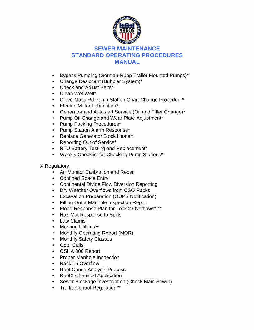
SEWER MAINTENANCE
STANDARD OPERATING PROCEDURES MANUAL
• Bypass Pumping (Gorman-Rupp Trailer Mounted Pumps)* • Change Desiccant (Bubbler System)* • Check and Adjust Belts* • Clean Wet Well* • Cleve-Mass Rd Pump Station Chart Change Procedure* • Electric Motor Lubrication* • Generator and Autostart Service (Oil and Filter Change)* • Pump Oil Change and Wear Plate Adjustment* • Pump Packing Procedures* • Pump Station Alarm Response* • Replace Generator Block Heater* • Reporting Out of Service* • RTU Battery Testing and Replacement* • Weekly Checklist for Checking Pump Stations*
X.Regulatory
• Air Monitor Calibration and Repair • Confined Space Entry • Continental Divide Flow Diversion Reporting • Dry Weather Overflows from CSO Racks • Excavation Preparation (OUPS Notification) • Filling Out a Manhole Inspection Report • Flood Response Plan for Lock 2 Overflows*,** • Haz-Mat Response to Spills • Law Claims • Marking Utilities** • Monthly Operating Report (MOR) • Monthly Safety Classes • Odor Calls • OSHA 300 Report • Proper Manhole Inspection • Rack 16 Overflow • Root Cause Analysis Process • RootX Chemical Application • Sewer Blockage Investigation (Check Main Sewer) • Traffic Control Regulation**

SEWER MAINTENANCE
STANDARD OPERATING PROCEDURES MANUAL
XI.Safety • Air Monitoring Procedures* • Confined Space Entry Procedure* • Fire Extinguisher Monthly Check* • Material Safety Data Sheet • Personal Protective Equipment* • Safety Contact Program
XII.Sewer Laterals
• Sewer Laterals – Commercial or Residential • Smoke Test* • Televising of Sewer Laterals
XIII.Timesheets
• Maintenance Section Timesheet • Overtime Timesheet
XIV.Work Order Database
• Work Order and Phone Call Log Bolded SOPs were written by Burgess & Niple/Brown & Caldwell for the CMOM Program. * SOP was previously written by the City of Akron but had not been included in their table of contents. ** SOP was previously written by the City of Akron and marked draft rather than final. *** SOP was moved to a different category than that originally listed. **** Replaces Forwarding FOG Locations to Health Department

Administrative

SEWER MAINTENANCE STANDARD OPERATING PROCEDURE
Administrative Support Field Operations
Area: Administrative
Title: GIS Record Drawing Data Entry
Status: Draft Final Original Date: 4/23/10 Revision Date:
Reviewers: Hewitt, Scarlatelli
Author: Burgess & Niple Revision Number: 0
INTRODUCTION/PURPOSE:
Upon completion of a sewer project (new sewers or repairs to existing sewers), record drawings are prepared by the City or the Contractor responsible for the installation/repair of the sewer components. These drawings are then submitted to the AEB for review. Once reviewed, the record drawings will be sent to the GIS technician for incorporation into the City’s GIS database. The steps below will ensure that the GIS database is updated in a timely manner with the information provided on the record drawings.
DETAILS:
1. Record drawings are received from the Contractor or AEB inspector and time stamped by AEB.
2. The AEB will update the record drawings and make corrections/changes and if acceptable forward to the Utilities Engineering Division.
3. The Utilities Engineering Division will time stamp the record drawings upon receipt.
4. The GIS technician will update the GIS database with the information from the record drawings per the Akron Sewer Bureau GIS Standards and Procedures manual.
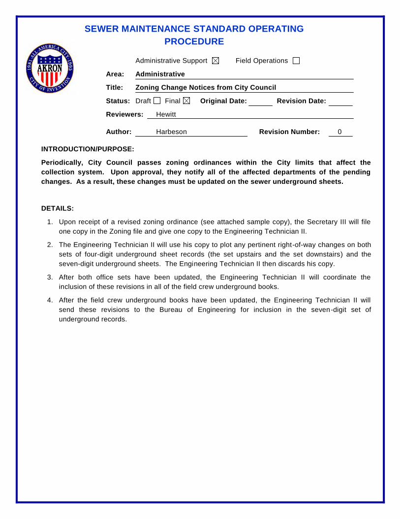
SEWER MAINTENANCE STANDARD OPERATING PROCEDURE
Administrative Support Field Operations
Area: Administrative
Title: Zoning Change Notices from City Council
Status: Draft Final Original Date: Revision Date:
Reviewers: Hewitt
Author: Harbeson Revision Number: 0
INTRODUCTION/PURPOSE:
Periodically, City Council passes zoning ordinances within the City limits that affect the collection system. Upon approval, they notify all of the affected departments of the pending changes. As a result, these changes must be updated on the sewer underground sheets.
DETAILS:
1. Upon receipt of a revised zoning ordinance (see attached sample copy), the Secretary III will file one copy in the Zoning file and give one copy to the Engineering Technician II.
2. The Engineering Technician II will use his copy to plot any pertinent right-of-way changes on both sets of four-digit underground sheet records (the set upstairs and the set downstairs) and the seven-digit underground sheets. The Engineering Technician II then discards his copy.
3. After both office sets have been updated, the Engineering Technician II will coordinate the inclusion of these revisions in all of the field crew underground books.
4. After the field crew underground books have been updated, the Engineering Technician II will send these revisions to the Bureau of Engineering for inclusion in the seven-digit set of underground records.

Infor
(previously Datastream 7i Extended)

SEWER MAINTENANCE STANDARD OPERATING PROCEDURE
Administrative Support Field Operations
Area: Infor (was previously Datastream 7i Extended)
Title: Creating and Completing Blank Maintenance Work Orders
Status: Draft Final Original Date: 04/14/09 Revision Date:
Reviewers: Hewitt
Author: Kline, Matthews, Nero Revision Number: 0
INTRODUCTION/PURPOSE:
To ensure regulatory compliance and document our daily work, we need to closely monitor our daily maintenance work. This SOP details the steps necessary to create and complete maintenance blank work orders from conception to completion.
DETAILS:
1. At the end of each day, the maintenance staff will turn in all blank work orders to their Supervisor/Foreman for review of the work performed for the day.
2. After the Supervisor/Foreman reviews the blank work orders for the day, they will give the blank work orders to the dispatcher on duty for either completion of existing work orders or creating and completing the blank work orders for the day.
3. The following steps are to be taken when creating/completing the maintenance blank work orders with “NEW” for Work Order Number in Infor:
a. Click on Record View tab
i. Click Icon to create a new work order ii. Work Order: First box work order number will be auto generated. In second
box enter information from “Type of Work / Problem” iii. Asset ID: Enter the asset ID. (Enter 1 of the possible 19 assets listed on the
provided sheet. If unsure, ASK). iv. Assigned to: Enter user ID of employees from blank work order (use the first
person listed under Names of People) v. Supervisor Assigned by: Enter user ID of workers supervisor (enter 1 of 4) vi. Class: Enter the work order class from the provided sheet (1 of 11) vii. Job Code: Enter job code from sheet viii. Date Reported: For new work orders enter date from data sheet and a time
of 8:00 AM, for work orders with a W. O. number already established, use date and time shown.
ix. Scheduled Start Date: Enter date work was done x. Start Date: Enter date and time work crew arrived on the job xi. Date Completed: Enter date and time work crew departed the job xii. Location Address: Enter location or address of work xiii. Time Arrived: Enter and time arrived on job xiv. Callers Name: Enter callers name xv. Phone: Enter callers phone number

SEWER MAINTENANCE STANDARD OPERATING PROCEDURE
xvi. Enter the quantity of work performed into the appropriate custom fields for the chosen work order class. Enter here even if already entered in comments or activity tab.
xvii. Click on the Save icon : Click here to save work order so far, Record auto generated work order number from Work Order box on Maintenance Blank Infor Work Order
b. Click on Comments Tab i. Add Comments: Enter everything from the Detail Description of Work
Preformed section of the 7i blank Work order
ii. Click on the Save icon : Click here to save work order so far
c. Click on Activities Tab i. Trade: Enter trade of employees working on this job, use spy glass look up
or cheat sheet ii. Estimated Hours: Enter total hours this trade worked on the job iii. Submittal No./People Required: Enter the total number of employees in this
trade needed to complete this job iv. Click Submit button v. Repeat steps a thru d for each different trade required to complete this job
d. Click on Book Labor Tab i. Employee: Enter first employees name that worked on job ii. Date Worked: Enter date on work order iii. Type of Hours: Enter code for hours type iv. Hours Worked: Enter the hours worked for this employee v. Click Submit button vi. Repeat steps a thru e for each employee and trade
e. Click on Tools and Usage Tab i. Tool: Enter any vehicle or towed equipment used on this job ii. Date Used: Enter date work done (do not use default date) iii. Quantity: Enter number of vehicles used iv. Hours Used: Enter hours used from sheet v. Click Submit button vi. Repeat steps a thru e for each vehicle used on the job.
f. Click on Record View tab i. Status: Change from Released to Completed
ii. Click on the Save icon : 4. The following steps are to be taken when completing an existing maintenance blank work
orders in Infor:

SEWER MAINTENANCE STANDARD OPERATING PROCEDURE
a. Go to the List View of the Work Orders
b. In the Dataspy Box, make sure it says “All”
c. In the Quick Filter Box, make sure it says “Work Order” and “Contains”. Then type in the work order number from the Blank Work Order form.
d. Once the work order is found, Click on Record View tab i. Job Code: Enter job code from sheet ii. Start Date: Enter date and time work crew arrived on the job iii. Date Completed: Enter date and time work crew departed the job iv. Time Arrived: Enter and time arrived on job v. Enter the quantity of work performed into the appropriate custom fields for
the chosen work order class. Enter here even if already entered in comments or activity tab.
vi. Click on the Save icon : Click here to save work order
e. Then follow above steps 3b thru 3f.
5. After all of the blank work orders are entered into Infor, the dispatcher will give the
blank work orders to the applicable foreman/supervisor. 6. The System Administrator will then perform daily audits on the data entry from the
previous day to check for accuracy of the information. 7. If any of the work orders have discrepancies, the System Administrator will reopen
the work order and enter into the comments on what information needs to be corrected.
8. The work order then will be assigned to the person who changed the status to
complete for corrections. 9. It will be the responsibility of the staff to check their inbox in Infor for any work
orders that need to be corrected and correct those work orders. If the staff does not have an inbox set up in the start center of Infor, contact the System Administrator for assistance in this matter.

SEWER MAINTENANCE STANDARD OPERATING PROCEDURE
Administrative Support Field Operations
Area: Infor (was previously Datastream 7i Extended)
Title: Data Entry for Snow and Ice
Status: Draft Final Original Date: 01/26/09 Revision Date:
Reviewers: Hewitt, MacBride
Author: Kline Revision Number: 0
INTRODUCTION/PURPOSE:
This SOP is being Created to document our actual costs to provide Snow and Ice services to Public Works. The details included in this SOP will allow us to accurately track our costs in Datastream 7i.
DETAILS:
1. The duty foreman for each snow event or shift is responsible for the steps outlined in this SOP (Section 1 bullets i through xii). In the event that we only have drivers loaned to Public Works, please refer to the steps at the end of this SOP.
i. Open and log into Datastream 7i.
ii. Create a new work order.
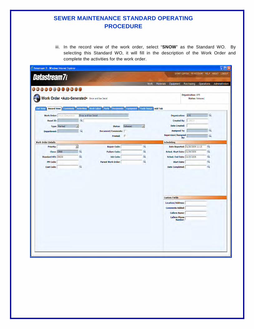
SEWER MAINTENANCE STANDARD OPERATING PROCEDURE
iii. In the record view of the work order, select “SNOW” as the Standard WO. By selecting this Standard WO, it will fill in the description of the Work Order and complete the activities for the work order.
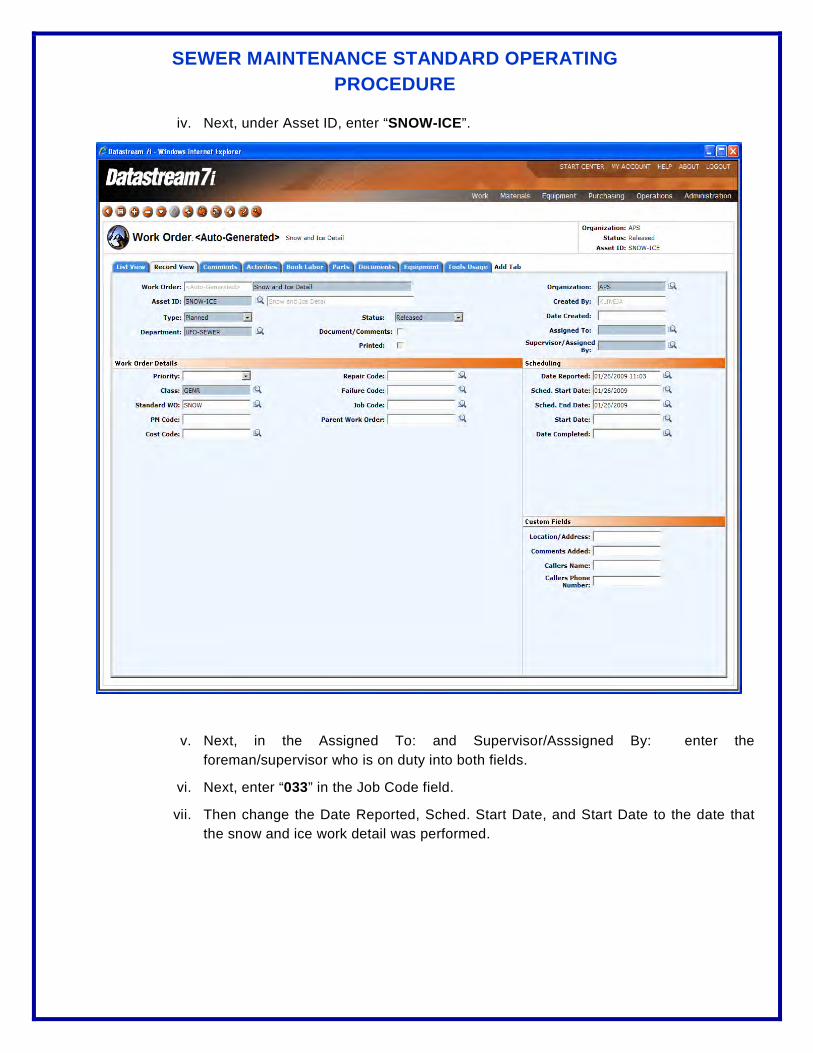
SEWER MAINTENANCE STANDARD OPERATING PROCEDURE
iv. Next, under Asset ID, enter “SNOW-ICE”.
v. Next, in the Assigned To: and Supervisor/Asssigned By: enter the foreman/supervisor who is on duty into both fields.
vi. Next, enter “033” in the Job Code field.
vii. Then change the Date Reported, Sched. Start Date, and Start Date to the date that the snow and ice work detail was performed.
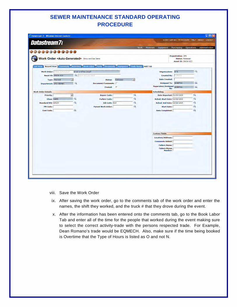
SEWER MAINTENANCE STANDARD OPERATING PROCEDURE
viii. Save the Work Order
ix. After saving the work order, go to the comments tab of the work order and enter the names, the shift they worked, and the truck # that they drove during the event.
x. After the information has been entered onto the comments tab, go to the Book Labor Tab and enter all of the time for the people that worked during the event making sure to select the correct activity-trade with the persons respected trade. For Example, Dean Romano’s trade would be EQMECH. Also, make sure if the time being booked is Overtime that the Type of Hours is listed as O and not N.

SEWER MAINTENANCE STANDARD OPERATING PROCEDURE
xi. After all of the personnel’s time has been booked onto the work order, go to the tools usage tab and add the tools used during the event. Most of the time the tools used will be “TRUCKDUMP3TN”, and a TRUCKPICKUP, making sure for the Tool: TRUCKDUMP3TN that the quantity be the number of trucks that were used for that shift. In some cases no tools will be added to a work order due to our personnel driving for other departments and our services for snow and ice are not needed.
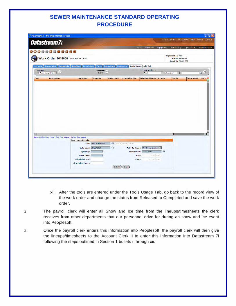
SEWER MAINTENANCE STANDARD OPERATING PROCEDURE
xii. After the tools are entered under the Tools Usage Tab, go back to the record view of the work order and change the status from Released to Completed and save the work order.
2. The payroll clerk will enter all Snow and Ice time from the lineups/timesheets the clerk receives from other departments that our personnel drive for during an snow and ice event into Peoplesoft.
3. Once the payroll clerk enters this information into Peoplesoft, the payroll clerk will then give the lineups/timesheets to the Account Clerk II to enter this information into Datastream 7i following the steps outlined in Section 1 bullets i through xii.
SEWER MAINTENANCE STANDARD OPERATING PROCEDURE
Administrative Support Field Operations
Area: Infor (previously Datastream 7i Extended)
Title: Documenting Complaints
Status: Draft Final Original Date: 4/27/10 Revision Date: 5/3/12
Reviewers: Hewitt, Scarlatelli
Author: Brown and Caldwell Revision Number: 1
INTRODUCTION/PURPOSE:
This SOP describes the process by which the City documents complaints and the action taken to respond to them.
DETAILS:
1. Dispatcher receives complaints via phone call from the public.
2. The Dispatcher generates a work order in Infor (was Datastream 7i) following the “Reactive Maintenance Workflow” using the processes outlined in the “Work Management” section of the Akron Sewer Bureau combined Field Operations Infor Users Guide, the Dispatcher or Supervisor assigns the work orders to a crew to investigate.
3. The Supervisor/Foreman reviews the completed work orders prior to entry into Infor to review the reactive maintenance work order status and response.

SEWER MAINTENANCE STANDARD OPERATING PROCEDURE
Administrative Support Field Operations
Area: Infor (previously called Datastream 7i Extended)
Title: Documenting Complaints
Status: Draft Final Original Date: 4/27/10 Revision Date:
Reviewers: Hewitt, Scarlatelli
Author: Brown and Caldwell Revision Number: 0
INTRODUCTION/PURPOSE:
This SOP describes the process by which the City documents complaints and the action taken to respond to them.
DETAILS:
1. Dispatcher receives complaints via phone call from the public.
2. The Dispatcher generates a work order in Infor (was Datastream 7i) following the “Reactive Maintenance Workflow” using the processes outlined in the “Work Management” section of the Akron Sewer Bureau Combined Field Operations Infor Users Guide, the Dispatcher or Supervisor assigns the work orders to a crew to investigate.
3. The Supervisor/Foreman reviews the completed work orders prior to entry into in Infor to review the reactive maintenance work order status and response.

DATASTREAM 7i STANDARD OPERATING PROCEDURE
Administrative Support Field Operations
Area: Datastream 7i Extended
Title: Keyboard Shortcuts
Status: Draft Final Original Date: 6/4/06 Revision Date:
Reviewers: J. Hewitt, S. Needham, T. Lohmier
Author: Jason Kline Revision Number: 0
INTRODUCTION/PURPOSE:
This Standard Operation Procedure (SOP) outlines the keyboard shortcuts that are available to all users of Datastream 7i Extended Release 7.10. These shortcuts will benefit all users in speeding up the ability to perform data entry and searches inside the application.
DETAILS:
The following is a list of keyboard shortcuts with a brief description:
1. F4 – By pressing this button on the keyboard, it will allow all users to duplicate (copy) the selected record just as if the user clicked on the copy record icon in the tool bar. This can be done in either the list view or the record view.
2. F6 – By pressing this button on the keyboard it will allow all users to insert a new record inside the selected field (i.e. Work Order, Part, Asset, etc.).
3. F7 – By pressing this button on the keyboard, it will allow all users to perform two different features inside the application. The first feature will initiate the spell check functionality inside the comments field inside the application. For example, if you are entering comments under the comment tab inside a work order and press the F7, it will perform a spell check on all text inside that box. The second feature by pressing F7, will allow users to initiate or hide the quick search tool bar inside the list view (cannot use F7 in the record view) of any selected item (i.e. Work Order, Parts, Assets, etc.)
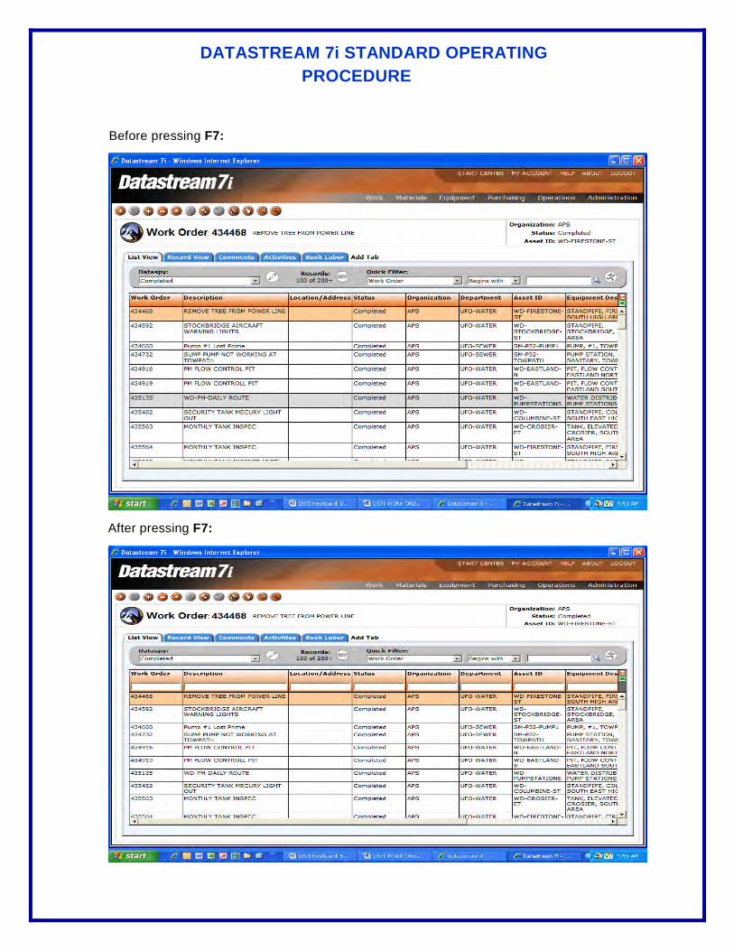
DATASTREAM 7i STANDARD OPERATING PROCEDURE
Before pressing F7:
After pressing F7:

DATASTREAM 7i STANDARD OPERATING PROCEDURE
4. F8 – By pressing this button on the keyboard, it will allow all users to initiate the quick search feature after the user enters a keyword into the fields of the quick search tool bar inside the list view.
5. F10 – By pressing this button on the keyboard, it will allow all users to save info into the database.
6. CTRL+T – By pressing these two keys together, it will allow all users to access the screen “My Account” where the users can change their password at any time.
7. CTRL+H – By pressing these two keys together, it will allow all users to access the “Help” screen.
10. ALT+Q – By pressing these two keys together, it will allow all users to Log Out of the application.
ENTERING DATES WITH KEYBOARD SHORTCUTS
Follow these steps to enter dates with keyboard shortcuts:
1. Position the cursor in the date field.
2. Choose one of the following options as necessary:
a. Enter the current date – press SPACEBAR. The system displays the current date in the field.
b. Enter a specific date or partial date – Press numeric keys to enter the desired date (e.g., 060507), and then press TAB to exit the field. The system evaluates the date and displays the closest match (e.g., 06/05/2007).
c. Use the “+” and “-“ keys to change the date when the cursor is in the date field. Press “+” key to add one day to the date. Press “-“ key to subtract one day from the date.

SEWER MAINTENANCE STANDARD OPERATING PROCEDURE
Administrative Support Field Operations
Area: Infor (was previously Datastream 7i Extended)
Title: Updating Project Tracking Log
Status: Draft Final Original Date: 4/27/10 Revision Date:
Reviewers: Hewitt, Scarlatelli
Author: Brown and Caldwell Revision Number: 0
INTRODUCTION/PURPOSE:
The City needs to maintain a log listing each sewer pipe and structure project completed during the previous year and the date the project was completed.
This SOP details the steps necessary to maintain this log, tracking both projects completed by contractors as well as maintenance performed by City crews.
DETAILS:
1. City-performed work:
a. The Planner/Scheduler will query Datastream 7i for completed work orders that performed corrective maintenance and add the information to the tracking spreadsheet.
b. Review each work order and record the pertinent details on the “City” worksheet of the “Project Tracking Log” spreadsheet.
2. Contractor-performed projects
a. Akron Sewer Bureau inspectors performing inspection of sewer installation and connections will record the following information related to the project’s work they are inspecting into the “Contractor” worksheet of the “Project Tracking Log” spreadsheet.
i. Project Name
ii. Contractor that performed the sewer installation or new connection
iii. Project Start Date
iv. Project Completion Date (from as-built drawing)
v. A list of asset IDs being inspected, one on each row of the spreadsheet
vi. For each asset, a description of the work performed to the asset
b. Update the cover worksheet of the spreadsheet to indicate the date and a brief description (e.g., project name) of the additions that were made.
SEWER MAINTENANCE STANDARD OPERATING PROCEDURE
Administrative Support Field Operations
Area: Infor (was previously Datastream 7i Extended)
Title: Work Orders for Daily Inspection of CSO Racks
Status: Draft Final Original Date: 2/22/07 Revision Date: 2/10/10
Reviewers: Hewitt, Rhodes, Soppi
Author: Kline Revision Number: 2
INTRODUCTION/PURPOSE:
To properly maintain the CSO racks, we need to closely monitor the daily inspection process of the CSO Racks. To achieve this, a preventive maintenance schedule has been developed inside Datastream 7i Extended. This SOP details the steps necessary to complete this from work order creation to completion.
DETAILS:
1. The planner/scheduler or System Administrator will generate the PM Schedule for the CSO Racks inside of Datastream 7i. The planner/scheduler or System Administrator will also create and print out a daily sheet with all of the work order numbers and blank fields for the rack crew to fill out as they visit each rack. See attached copy of the form.
2. The Dispatcher will then give these Work Orders to the rack crew each day for completion.
3. The Rack crew will then fill in all of the information in the blank boxes of the printed out work order. The attached sample is what information should be included on the work order.
4. At the end of the day, the Rack crew will turn in the work orders for the inspection of the CSO Racks for that day to the Supervisor/Foreman.
5. The Supervisor/Foreman will review the Work Orders to ensure they have been filled out correctly. After which, they will turn the filled out work orders into the 4:00 p.m. Dispatcher for data entry in Datastream 7i.
6. The Dispatcher on duty at 4:00 p.m. will then open and complete all of the information required for completing the work orders inside Datastream 7i. To find these work orders daily in Datastream, follow these steps:
a. Start by logging into Datastream 7i.
b. Once logged into Datastream 7i, double click “CSO Rack Preventive WO’s” line in the Inbox of the Start Center. If the “CSO Rack Preventive WO’s” does not appear in the Inbox, contact the System Administrator to add this to your Inbox.

SEWER MAINTENANCE STANDARD OPERATING PROCEDURE
c. After completing the prior step, the following screen should display:

SEWER MAINTENANCE STANDARD OPERATING PROCEDURE
7. After completing the above step, the Dispatcher on duty must open up each individual work order and enter all of the applicable information for that work order. This includes all of the required information in the record view: the information collected from the field, book labor, and the tools used (which are located under the “Tools Usage Tab” in Datastream 7i). If you have any problems performing this task, please refer to the training guide or contact the System Administrator. After all information has been entered, change the status of the work order to “Completed” and file the paper copy.

SEWER MAINTENANCE STANDARD OPERATING PROCEDURE
Administrative Support Field Operations
Area: Infor (was previously Datastream 7i Extended)
Title: Work Orders for Main Sewer Blockages
Status: Draft Final Original Date: 9/11/09 Revision Date:
Reviewers: Hewitt, Kline
Author: Joseph Revision Number: 0
INTRODUCTION/PURPOSE:
Based on our limited resources, reduced staff, and additional requirements from the EPA, we need to carefully document the occurrence and cause of all separate sewer and combined sewer system releases. To achieve this, a list of the variables associated sewer system releases need to be recorded inside Datastream 7i Extended. This SOP details the steps necessary to complete this from conception to completion.
DETAILS:
When an overflow has been stopped and the release eliminated, the Sewer Maintenance crew completes the work order that was created by the dispatcher in response to the receipt of information regarding a sewer release. The crew will fill in all of the information in the blank boxes of the printed out work order. The following is a list of the information that should be included on the work order:
1. Indication that the sewage overflow had reached surface waters, i.e., all overflows where sewage was observed running to surface waters, or there was obvious indication (e.g. sewage residue) that sewage flowed to surface waters; and
2. Indication that the sewage overflow had not reached surface waters. Guidance in characterizing these overflows may include: • Sewage overflows to covered storm drains (with no public access) where
personnel verify, by inspection, that the entire volume is contained in a sump or impoundment and where complete clean-up occurs leaving no residue.
• Preplanned or emergency maintenance jobs involving bypass pumping if access by the public to a bypass channel is restricted and subsequent complete clean-up occurs leaving no residue (Any preplanned bypass under these circumstances will not be considered an overflow unless done without authorization by the Sewer Maintenance Division Superintendent or Akron Sewer Bureau Manager.); and
• An overflow where observation or on-site evidence clearly indicates all sewage was retained on land and did not reach surface water and where complete cleanup occurs leaving no residue.
3. Location where the overflow occurred including: • Street addresses where the overflow occurred or the nearest address to an
overflow that occurred within the right-of-way. • City of Akron GIS ID of the structure where the sewage is overflowing from
the system 4. Cause of the overflow including:

SEWER MAINTENANCE STANDARD OPERATING PROCEDURE
• The GIS ID number of the upstream and downstream structures as well as the sewer section that contained the cause of the overflow.
• If the overflow was caused by a blockage, the material causing the blockage shall be identified, if possible.
5. Determination of the start time of the sewer overflow by one of the following methods: • Date and time information received and/or reported to have begun and later
substantiated by a sewer investigator or response crew; • Visual observation; or • Pump station and lift station flow charts and other recorded data including
information available from the Sewer Maintenance SCADA System. 6. Determination of the stop time of the sewer overflow by one of the following
methods: • When the blockage is cleared or flow is controlled or contained; or • The arrival time of the sewer investigator or response crew, if the overflow
stopped between the time it was reported and the time of arrival. 7. Visual observations - An estimation of the rate of sewer overflow in gallons per
minute (GPM) by one of the following criteria: • Direct observations of the overflow; or • Measurement of actual overflow from the sewer main.
8. Determination of the volume of the sewer overflow: • When the rate of overflow is known, multiply the duration of the overflow by
the overflow rate; or • When the rate of overflow is not known, investigate the surrounding area for
evidence of ponding or other indications of overflow volume. 9. Photographs of the event, when possible. 10. Assessment of any damage to the affected areas of public/private property.
At the end of the day, the Crew will turn in the work order for their response to the sewer release to the Supervisor/Foreman.
The Supervisor/Foreman will review the Work Orders to ensure they have been filled out correctly. After which, they will turn the filled out work orders into the 3:00 p.m. dispatcher for data entry in Datastream 7i.
After completing the above step, the dispatcher on duty must open up each individual work order and enter all of the applicable information for that work order. This includes all of the required information in the record view: the information collected from the field, book labor, and the tools used (which are located under the “Tools Usage Tab” in Datastream 7i. If you have any problems performing this task, please refer to the training guide or contact the System Administrator. After all information has been entered, changes the status of the work order to completed and file the paper copy.

Dispatcher
SEWER MAINTENANCE STANDARD OPERATING PROCEDURE
Administrative Support Field Operations
Area: Dispatcher
Title: Dispatcher Communications
Status: Draft Final Original Date: 1/24/05 Revision Date:
Reviewers: Hewitt, Greer, Cook
Author: Kline Revision Number: 0
INTRODUCTION/PURPOSE:
Based on our limited resources and reduced staff, we need to closely monitor communications between the shift changes of the dispatchers. This SOP details the steps necessary to complete this from conception to completion.
DETAILS:
1. For all incoming calls, ask the caller for cross streets.
2. Review the work order database from the previous shift.
3. Check the work order database for the outcome of Check Main Sewer’s during the day.
4. Notify the in-coming dispatcher if there are crews out or coming in and the names of the people. For example, if there is a crew out in the field checking a main, rack alarm, or pump station alarm, notify the in-coming dispatcher on what crew is out and what their location is at that time. Another example is that if there are people in on Snow & Ice, notify them of who the drivers are driving, who is the supervisor/foreman in at the time, and if there are any mechanics on duty.
5. Notify the in-coming dispatcher of what trucks are up to be used (e.g. water truck, vac truck, etc.) Also notify the in-coming dispatcher of what trucks are out of service.
6. Notify the in-coming dispatcher of who should not be called in for overtime. For example, if the person is suspended or called off sick for the day.
7. Notify the in-coming dispatcher of any unfinished work orders. For example, check a main at 1055 Home.
8. Notify the in-coming dispatcher of any problems in an area that may need checked on periodically. For example, a plugged sewer or badly broken sewer. Also have the underground sheet out for reference for that area.
9. Notify the in-coming dispatcher of any problems in the building (e.g. alarms, doors, broken window, etc.)
10. Notify the in-coming dispatcher of what problems not to respond to (e.g. rack alarm, pump station alarm, etc.)
11. Remind all overtime crews to take a meter and a mag to check for gas.
APPROVAL/ROUTING PROCESS:
SEWER MAINTENANCE STANDARD OPERATING PROCEDURE
Administrative Support Field Operations
Area: Dispatcher
Title: Flag Responsibilities
Status: Draft Final Original Date: Revision Date:
Reviewers: Hewitt
Author: Kline Revision Number: 0
INTRODUCTION/PURPOSE:
The purpose of this SOP is to explain the proper procedure on displaying The United States of America and the City of Akron flags. It is the responsibility of all the dispatchers to follow these guidelines.
DETAILS:
1. The flag should be displayed on all days, except during inclement weather.
2. The flag should be flown from sunrise to sunset.
3. The flags should be hoisted briskly and lowered ceremoniously.
4. The flags are never allowed to touch the ground or floor.
5. The flag of the United States of America should be at the center and at the highest point of the group when a number of flags of States or localities or pennants of societies are grouped and displayed from staffs.
6. The flags should never be festooned, drawn back, nor up in folds but always allowed to fall free.
7. The flags should be displayed at half staff until noon on Memorial Day then raised to the top of the staff.
8. Never fly the flag upside down except as a signal of distress in instances of extreme danger to life or property.
9. The flags should be displayed at half staff for 30 days when a president or former president dies.
10. The flags should be displayed at half staff for 10 days when current or former vice president, chief justice, or speaker of the house dies.
11. The flags should be displayed at half staff for one day when a governor, US senator, or US representative dies.

SEWER MAINTENANCE STANDARD OPERATING PROCEDURE
Administrative Support Field Operations
Area: Dispatcher
Title: Preparing the Dirt List
Status: Draft Final Original Date: Revision Date:
Reviewers: Hewitt
Author: Cook Revision Number: 0
INTRODUCTION/PURPOSE:
The purpose of this SOP is to accurately detail how the dirt list is created on a daily basis.
DETAILS:
1. Each evening, review that day’s timesheets for dirt piles that were created for that day.
2. List the dirt piles that were on the timesheets on the standard “DIRT LIST” form located in the dispatcher’s office.
3. Place the completed dirt list form with the work orders to complete the next day.

SEWER MAINTENANCE STANDARD OPERATING PROCEDURE
Administrative Support Field Operations
Area: Dispatcher
Title: SCADA System
Status: Draft Final Original Date: 12/1/05 Revision Date: 5/4/12
Reviewers: Hewitt, Cory, Cook
Author: Kline Revision Number: 1
INTRODUCTION/PURPOSE:
DETAILS:
FOR PUMP STATIONS
1. When alarm sounds on the SCADA system, look at the alarming station.
2. To silence an alarm, press the F1 key on the keyboard.
3. Move the cursor to alarming station and click on that station. Alarms will be in red at the top of the screen.
4. If you see a power fail alarm, it means that there is no commercial power. Make sure that the generator is working on that station.
5. If you see an all pump fail alarm, it means there are no pumps running at that particular pump station.
6. If you see a wet well high alarm, it means that the wet-well high water level is up.
7. If you see a lead pump fail alarm, it means that the lead pump is not working.
8. If you see a lag pump fail alarm, it means that the lag pump is not working.
9. If you see a communications alarm, it means that there is no communication signal being received for that particular pump station.
10. When an alarm sounds for a station, click on the update button for that particular station and wait 10 minutes to see if the alarm clears for that station.
11. If the alarm clears, there is no action needed. If alarm does not clear, follow the following procedure.
a. On the pump station sites, go to operator help at the top right hand corner of the screen to see what action is needed.
b. If you need to call in a crew after working hours, go to the overtime list for dispatcher, maintenance and pump. You can access this by double clicking on the icon on the dispatcher computer.

SEWER MAINTENANCE STANDARD OPERATING PROCEDURE
c. At the bottom of the list, select the tab that reads “PUMP” and call in the next mechanic that is available. Always call in TWO mechanics.

SEWER MAINTENANCE STANDARD OPERATING PROCEDURE
d. If you can not get a pump station mechanic to come in, call the pump station foreman. If the foreman is not available, call Billy Rhodes.
FOR RACK ALARMS
12. When alarm sounds on the SCADA system, look at the alarming station.
13. To silence an alarm, press the F1 key on the keyboard.
14. During regular working hours, when an alarm sounds for a rack, immediately dispatch a rack crew to investigate the problem.
15. After regular working hours, when an alarm sounds for a rack, click the update button for that particular rack and wait 15 minutes to see if the alarm clears for that station. If the overflow alarm does not clear, call in the next available foreman.
16. If you need to call in a foreman, go to the overtime list for dispatcher, maintenance and pump. You can access this by double clicking on the icon on the dispatcher computer.

SEWER MAINTENANCE STANDARD OPERATING PROCEDURE
17. Then proceed to the maintenance foreman list and find the next available foreman and send him to the alarming rack that is overflowing.

SEWER MAINTENANCE STANDARD OPERATING PROCEDURE
18. Only dispatch crews/foreman when it is a dry-weather overflow.
19. If the alarm is a communication failure, press the update button every hour until it clears. DO NOT CALL A FOREMAN/CREW IN TO CHECK.

SEWER MAINTENANCE STANDARD OPERATING PROCEDURE
Administrative Support Field Operations
Area: Dispatcher
Title: Security Monitoring and Recording
Status: Draft Final Original Date: 10/21/04 Revision Date:
Reviewers:
Author: Revision Number: 0
INTRODUCTION/PURPOSE:
The security camera system was installed several years ago to protect our facility from fraud and theft. It is imperative that this system functions properly to protect our interests.
Security Cameras: There are four cameras strategically placed inside and outside the facility.
Security Monitor: It is located in the dispatch office where it is monitored 24 hours a day.
Security Tapes: We are currently using six-hour VHS tapes that are changed every six hours.
Video Log: This is used to log every time that a tape is changed or there is a problem with the system.
Security System Recorder: We are currently using a VCR located in the dispatcher's office to record the security system.
Management: Your immediate supervisor or the Superintendent.
DETAILS:
1. Insert a six-hour VHS tape in the security system VCR.
2. Push the record button on the VCR to begin recording.
3. Push the VCR button on the security monitor and make sure that the green light is lit.
4. Make sure that there is a picture on the screen of the security monitor. If you do not have a picture on the screen of the security monitor, check the VCR and make sure that it is set on channel L1. If it is not on channel L1, the VCR will not record the signal from the video cameras and the tapes will remain blank.
5. List the VHS tape number and the time of day on video log sheet. This must be kept up to date and accurate to ensure that the proper tapes are tracked for each shift.
6. Ensure that the system is recording properly.
7. Ensure that the camera rotation is working properly. The screen data should rotate among the four video cameras. The red light must be lit over the Auto Skip button on the security monitor.
8. If one of the cameras happens to fall out of the rotating loop, press the camera button for that specific camera and the Auto skip button at the same time and hold for three seconds. This should

SEWER MAINTENANCE STANDARD OPERATING PROCEDURE
put the camera back in the rotating loop. (Make sure that the Auto Skip button red light remains lit after this procedure.)
9. Do not use the security VCR or monitor for any function other than recording the security system.
10. Notify Management if the system is not working properly and correct the problem.
11. Repeat steps 1 through 10 every six hours. Specifically, this should be done at 6:00 am, 12:00 pm, 6:00 pm, and 12:00 am every day.
APPROVAL/ROUTING PROCESS:

SEWER MAINTENANCE STANDARD OPERATING PROCEDURE
Administrative Support Field Operations
Area: Dispatcher
Title: Security System
Status: Draft Final Original Date: 1/3/06 Revision Date:
Reviewers: Hewitt
Author: McCall, Cook Revision Number: 0
INTRODUCTION/PURPOSE:
One of the night dispatcher's core duties is building security. This SOP will detail step-by-step how to secure the facility by locking the gates, turning on the alarm system, and monitoring the surveillance system.
DETAILS:
1. After all of the crews have left for the day, lock both gates on the north and south sides of the building.
2. After locking the gates, walk around the entire building making sure all doors are closed and locked including the entrances upstairs.
3. Next, activate the alarm system for the building. The following steps will describe the proper format for activating and de-activating the alarm system:
a. The following picture shows the alarm system key pad. It will help you understand what buttons need to be pressed when activating and deactivating the alarm system.
b. First thing to check when activating the alarm is make sure there are no faults in the system. When the system is ready to be armed, the green light left of the key pad will flash.
c. Now, enter your 4-digit code by using the key pad on the left side of the panel. If you cannot remember your 4-digit code, request the code from the superintendent.
SEWER MAINTENANCE STANDARD OPERATING PROCEDURE
d. After entering your 4-digit code, press the #2 key (AWAY).
e. The next screen you will see on the system will ask you whether or not to arm the entire system. Select YES.
f. After you arm the system, make sure you do not go upstairs, the garage, or by the overhead garage doors because you will set the alarm off.
g. To deactivate the alarm, enter your 4-digit code.
h. After entering your 4-digit code, press the #1 key (OFF).
i. If alarm sounds, the alarm company will call and ask for a password. The password is ODORS. If you do not give them the password, the alarm company will send the police.
j. NOTE: BEFORE UNLOCKING THE GATES AND DOORS, MAKE SURE THE ALARM SYSTEM IS DISARMED!
4. Each day, Monday through Friday excluding any holidays, make sure all doors and the north and south gates are unlocked by 6:30 a.m. Also, make sure the alarm system is disarmed by this time.
5. For weekends and holidays, unlock only the north gate to the facility and the entrance door to the building on the north side by 6:30 a.m. Also, make sure the alarm system is disarmed by this time.
SEWER MAINTENANCE STANDARD OPERATING PROCEDURE
Administrative Support Field Operations
Area: Dispatcher
Title: Sewer Emergencies – Dispatch Communication Protocol
Status: Draft Final Original Date: 5/8/12 Revision Date:
Reviewers: Scarlatelli
Author: Brown and Caldwell Revision Number: 0
INTRODUCTION/PURPOSE:
The Sewer Maintenance Dispatch Office is the main receiving location for reports of sewer problems from the public, from other City employees and the SCADA system. To provide good customer service and to minimize adverse effects on public health, public safety and the environment, quick, effective and accurate communication is vital. This SOP applies, in general, to most calls received including reports of potential sewage overflows. More detailed information on dispatching and response to a potential overflow can be found in the Sewer Overflow Response and Notification Plan (SORNP) Section III A. and B.
DETAILS:
1. For all incoming calls, ask the caller for the specific location of problem, the closest cross streets, and a description of the problem. Also obtain any additional information from the caller relating to observations of the problems. (e.g. odors, duration, rear yard location, etc.)
2. Create a work order capturing all the relevant information pertaining to the reported problem as obtained in step one above.
3. Notify the appropriate crew to mobilize to the location of the reported problem by the quickest communication tool available, whether it is by radio or by telephone.
4. Verify that the entire message has been received and acknowledged by the crews who were dispatched.
5. If a call is received reporting a potential sewage overflow, IMMEDIATELY notify the appropriate supervisor with the quickest communication tool available, whether it is by radio or by telephone.
6. Based on instructions from the supervisor, dispatch the appropriate crew to the location so the possible effects of an overflow can be minimized as quickly as possible.
7. If a Pump Station failure is received through the SCADA system, IMMEDIATELY convey all information regarding the alarm to the pump station personnel to initiate an investigation.
8. The work order will be completed by the crew dispatched to the location (or the supervisor) and provided to the planner/scheduler for input into INFOR.
9. If a problem continues to be addressed in the field through changing of shifts, refer to SOP – Dispatcher Communication – for information to communicate to the incoming Dispatcher.
APPROVAL/ROUTING PROCESS:

SEWER MAINTENANCE STANDARD OPERATING PROCEDURE
Administrative Support Field Operations
Area: Dispatcher
Title: Signing Out Meters, Radios, Dehumidifiers, Shop Vacs, etc.
Status: Draft Final Original Date: Revision Date: 8/23/06
Reviewers: Hewitt
Author: McCall, Cook Revision Number: 1
INTRODUCTION/PURPOSE:
The intent of this SOP is to establish procedures to sign out gas meters, handheld radios, shop vacs, dehumidifiers, etc. These items are very expensive to replace and are essential for your personal protection. Therefore, it is imperative that they are signed out and returned on a daily basis. This will ensure that they are not lost, damaged, or need to be recharged before they are signed out again.
DETAILS:
1. For signing out meters and radios, the dispatcher will unlock the storage cabinet and hand you the sign-out slip shown below to fill out.
2. Make sure the person signing out a meter or radio fills in all of the appropriate information.
3. When the person has filled out all of the information needed on the sign-out slip, he/she is to hand the completed sign-out slip to the dispatcher.
4. The dispatcher will attach the sign-out slip to the appropriate sign-out board located in the dispatch office and lock the storage cabinet.

SEWER MAINTENANCE STANDARD OPERATING PROCEDURE
5. When you return a meter or radio, make sure you notify the dispatcher on duty that you are returning it so the dispatcher can unlock the storage cabinet. They will remove the slip from the sign-out board and place the unit on its applicable charger.
6. When someone needs a dehumidifier or a shop vac, that person needs to request the item from the dispatcher on duty. At that point, the dispatcher will unlock the cabinet where the dehumidifiers and shop vacs are stored.
7. Before the person takes responsibility of the item they are requesting, they need to sign out the item on the following sign-out sheet with all of the information required.
8. When returning a dehumidifier or shop vac, notify the dispatcher that you are returning the item. The dispatcher will then unlock the cabinet.
9. When the cabinet is unlocked, place the item back in the cabinet and sign in the item.

Inventory
SEWER MAINTENANCE STANDARD OPERATING PROCEDURE
Administrative Support Field Operations
Area: Inventory
Title: Commissioning and Decommissioning of Inventory Asset
Status: Draft Final Original Date: 4/22/10 Revision Date:
Reviewers: Hewitt, Scarlatelli
Author: Burgess and Niple Revision Number: 0
INTRODUCTION/PURPOSE:
This procedure is meant to assist in the commissioning and decommissioning process for equipment and components of the sewer system.
The equipment commissioning/decommissioning procedure provides a record of each equipment/component installation/removal in Datastream 7i, FleetFocus and/or GIS, as required, and the associated review process.
DETAILS:
1. Associated documents:
a. Equipment O&M manuals
b. Manufacturers start-up check-lists
c. Equipment specifications (from project Contract Documents if applicable)
2. Commissioning
a. City will verify that:
i. Required construction activities are completed, including activities by other entities that would interrupt the normal operations of the equipment/system component.
ii. Required testing, adjusting, and balancing are completed.
iii. Adequate/specified spare parts and supplies for routine maintenance and replacement are on hand to support system operation.
iv. O&M Manuals have been provided to the City.
v. Repair parts and maintenance materials have been delivered to the City.
vi. Record drawings have been provided by Contractor/City.
vii. The field verification of the O&M instruction/training has been completed.
3. Decommissioning
The City will verify that:

SEWER MAINTENANCE STANDARD OPERATING PROCEDURE
a. Required construction activities are completed, including activities by other entities that would interrupt the normal operations of the equipment/component.
b. Required testing, adjusting, and balancing are completed on the new equipment/component (if replacing an existing piece of equipment or component) and the new equipment/ component is operational.
c. Power sources and utilities have been properly disconnected and billing accounts canceled as applicable.
d. Storage tanks, fuel tanks, oil reservoirs have been emptied.
e. Remove equipment/system component or abandon component in place if feasible.
f. Dispose of decommissioned equipment/component and any spare parts in inventory specifically for the decommissioned equipment, as directed by Superintendent.
i. Scrap
ii. Store for future sale/auction
iii. C&D Landfill
iv. Other
4. Inventory Update (Datastream/FleetFocus/GIS)
After completing the commissioning/decommissioning procedures Foreman/Supervisor will:
a. Provide equipment/component nameplate or other relevant data to the Account Clerk, Planner Scheduler or GIS Technician for updating the appropriate database.
b. Equipment/component information will be added/deleted to the respective database as required by Account Clerk or GIS Technician.
c. Synchronize Datastream and GIS for new asset.
d. Assign appropriate planned maintenance work orders for equipment/component in Datastream or FleetFocus.

SEWER MAINTENANCE STANDARD OPERATING PROCEDURE
Administrative Support Field Operations
Area: Inventory
Title: Conducting Annual Inventory of Equipment and Spare Parts
Status: Draft Final Original Date: 4/22/10 Revision Date:
Reviewers: Hewitt, Scarlatelli
Author: Burgess & Niple Revision Number: 0
INTRODUCTION/PURPOSE:
Provide procedures for conducting the annual inventory of Sewer Maintenance equipment and spare parts. The annual inventory will be conducted prior to the end of the fiscal year but no earlier than October 1 of each year.
DETAILS:
EQUIPMENT:
1. Account Clerk will print out inventory lists from Datastream 7i and from FleetFocus for sewer maintenance equipment and parts and distribute to Foremen/Supervisors:
a. Vehicles
b. Pump stations
c. Racks
d. Air Release Valves
e. Storerooms:
i. SM001 – Maintenance (DataStream)
ii. SM002 – TV (DataStream)
iii. SM003 – Construction (DataStream)
iv. SM005 – Pump Station Non-Inventory (DataStream)
v. SM005a – Pump Station (DataStream)
vi. SM006 – Non-Inventory (DataStream)
vii. SM-Home – Vehicle Inventory Sewer Maintenance Purchase (FleetFocus)
viii. SM-Moto – Vehicle Inventory Motor Equipment Purchase (FleetFocus)
2. Foreman/Supervisor will distribute inventory lists to employees to check quantities on the lists for accuracy and completeness.
3. Employee will note discrepancies to inventory items on the list (i.e. different quantity, different size, serial number, model number, make, etc).
4. The employee will turn the revised inventory list into his/her Foreman/Supervisor.

SEWER MAINTENANCE STANDARD OPERATING PROCEDURE
5. Foreman/Supervisor will check inventories and comments and turn inventories into the Account Clerk.
6. An attempt will be made to locate missing items noted on the inventory. A list of missing items will be compiled once the inventory has been completed.
7. The Account Clerk will revise the inventories according to the corrected versions.
8. Account Clerk will submit the final inventory list to the Finance Department.
SEWER MAINTENANCE STANDARD OPERATING PROCEDURE
Administrative Support Field Operations
Area: Inventory
Title: Entering Parts into Inventory and Charging Them to Work
Status: Draft Final Original Date: 7/18/06 Revision Date: 12/9/08
Orders
Reviewers: Hewitt, MacBride
Author: Lee, Kline Revision Number: 1
INTRODUCTION/PURPOSE:
The purpose of this SOP is to create a process to accurately track parts in inventory. This SOP will outline the steps to receive parts, enter them into inventory, and charge them to work orders.
DETAILS:
1. Double check that the number of items received matches what is listed on the original invoice or packing slip.
Receiving:
2. If the company has only listed the item by some code or abbreviation, please write in the name of the item on the original invoice or packing slip. For example: coupler, screws, bolts, fitting, hose, etc.
3. If the company has only listed the items shipped on the invoice or packing slip, the foreman/supervisor shall call the supplier to get an itemized price for the items received and write the prices on the original invoice or packing slip.
4. If the parts received were purchased using a Motor Equipment PO, please write on the original invoice or packing slip M.E. PO. If the parts received were purchased using a Sewer Maintenance PO, please write Sewer PO on the original invoice or packing slip.
5. If the items received need to be entered into Datastream 7i, please write on the original invoice or packing slip on what storeroom that the items need to be entered. For example, SM-001 (Maintenance Storeroom), SM-002 (TV Storeroom), SM-003 (Construction Storeroom), SM-005 (Pump Station Storeroom). Storeroom SM-006 (Non-Inventory Storeroom) is for special parts received that are either directly used for a work order or for parts that do not need to be inventoried at the end of the year.
6. If the item(s) received are directly installed on a specific work order and does not need to be entered into a specific storeroom, please write on the original invoice or packing slip the Datastream 7i work order number and storeroom number SM-006 (Non-inventory Storeroom) and issue/assign that specific work order to MACBRGL in Datastream after all of the Custom Fields, Comments, Activities, and Hours Booked has been completed by the supervisor/foreman.

SEWER MAINTENANCE STANDARD OPERATING PROCEDURE
7. After all of the above information has been gathered or completed make a copy of the original invoice or packing slip for your records and give the original to the Account Clerk (Gloria MacBride) for data entry.
8. The Account Clerk will then enter all of the above information into a storeroom and if necessary will issue the parts to a specific work order number and complete that work order in Datastream 7i.
9. After the information from the invoice or packing slip has been entered into Datastream 7i, the Account Clerk will make a copy of the original invoice or packing slip for their records and give the original to the Secretary III (Pam Pollock) for payment to the vendor.
1. When taking items out of the storeroom, please fill out the following information on the form located by the storeroom door:
TAKING ITEMS OUT OF THE STOREROOMS FOR USE ON A JOB/WORK ORDER:
a. The date the item was removed from the storeroom.
b. The description of the item and/or part number.
c. The quantity of each item taken from the storeroom.
d. The Datastream 7i Work Order Number (if applicable)
e. The truck number of the vehicle taking the item.
SEWER MAINTENANCE STANDARD OPERATING PROCEDURE
Administrative Support Field Operations
Area: Inventory
Title: Items Received and Items Used
Status: Draft Final Original Date: 7/18/06 Revision Date:
Reviewers: Jim Hewitt
Author: Annette Lee Revision Number: 0
INTRODUCTION/PURPOSE: To outline standard procedures when receiving items from vendors,
and to track items taken for use on the job.
DETAILS:
RECEIVING -
1.) Double check that the number of items we got matches what is listed on the invoice.
2.) Please sign your name on the invoice.
3.) Please write-in the date, if it isn’t there.
4.) If the company has only listed the item by some code or abbreviation, please write in the name of the item, such as: coupler, screws, bolts, fitting, hose.
5.) If you used Motor Equipment’s purchase order number, write: M.E.PO, if you used ours, just write:
Sewer PO, anywhere on the invoice
6.) Put the invoice in the wire basket on the counter, or bring it upstairs to Annette or Pam.
TAKING ITEMS TO USE ON THE JOB –
1.) You can write it on the tablet at the Storeroom door. Please give the name of the item, and the part number, how many, the date, and your vehicle number.
2.) Or, you can write on your timesheet, such as: “locking manhole cover”, and the address you used it.
SEWER MAINTENANCE STANDARD OPERATING PROCEDURE
Administrative Support Field Operations
Area: Inventory
Title: Storeroom
Status: Draft Final Original Date: Revision Date:
Reviewers: Hewitt
Author: Soppi Revision Number: 0
INTRODUCTION/PURPOSE:
This SOP is necessary to accurately track our inventory items and provide a means to reorder supplies before they run out.
DETAILS:
1. Each foreman will be issued a storeroom requisition pad with pre-numbered requisition forms. The foreman is responsible for the pad and must sign all requisitions. The storeroom will keep track of the requisition numbers assigned to each foreman.
2. An employee can obtain materials from the storeroom if he presents a requisition. The foreman will keep the blue copy in his pad and give the employee the white and yellow copies to take to the storeroom.
3. The storeroom personnel will secure the materials or call the Yard Operator to secure the materials.
4. The employee obtaining the materials from the storeroom must sign the requisition on the "received by" blank when he receives the materials.
5. The storeroom will keep the white and yellow copies. The white copies will be used for auditing purposes. The yellow copies will be turned into the Yard Supervisor by the storeroom for review. The Yard Supervisor will then return the yellow copies to the appropriate foreman through his supervisor. The foreman shall then reconcile the yellow copies with the blue copies in his requisition pad.
6. The foreman must turn in the completed requisition pad (with all the blue copies) to the storeroom before a new pad will be issued.
7. If a mistake is made when filling out a requisition, the requisition shall be marked "void" and kept with the requisition pad.
8. If a particular material needs to be issued from the yard, the person requisitioning the material will be given the yellow copy after signing the requisition, which in turn must be given to the Yard Operator to obtain the material.
9. The Yard Operator will initial the yellow copy, indicating that the material has been taken, and will turn the yellow copy back into the storeroom.
SEWER MAINTENANCE STANDARD OPERATING PROCEDURE
10. If the foreman is not available and the crew needs materials, the employee must contact another foreman or one of the supervisors, who will each have their own pad for requisitioning materials. The foreman or supervisor must sign the requisition before materials will be issued and must indicate which foreman he is signing for.
11. Each requisition shall include the truck number to which the material was assigned.
12. Each month, the storeroom will provide each supervisor with an itemized list of the quantities of materials signed out by each foreman in his section during the preceding month. For each type of material, totals will be given for the month and for the year to date. The supervisor will review this report.
13. An "acting" foreman (temporary class change) will be permitted to issue a requisition with approval by their supervisor.
14. Previous requirements for tools and equipment will still apply in regards to turning in the old tool or piece of equipment before a new one is issued.
15. If necessary, a foreman or supervisor may call the storeroom and give a verbal authorization for an employee to take materials from the storeroom. The storeroom personnel will fill out the requisition, and the foreman or supervisor will be responsible for signing the requisition by the end of the shift.
16. A requisition shall also be filled out for all materials returned to the storeroom. The requisition shall be clearly marked "C.M." (for credit memo) or the word "returned" written on it.

Maintenance
SEWER MAINTENANCE STANDARD OPERATING PROCEDURE
Administrative Support Field Operations
Area: Maintenance
Title: Adding and Removing Trouble Spot Cleaning Location from
Status: Draft Final Original Date: 4/19/10 Revision Date:
List
Reviewers: Hewitt, Scarlatelli
Author: Brown and Caldwell Revision Number: 0
INTRODUCTION/PURPOSE:
The City of Akron performs proactive cleaning of locations identified to have recurring O&M issues, such as debris, grease, etc. The list and schedule for when they are to be cleaned is managed through the computerized maintenance management system (CMMS) Datastream 7i through the PM Schedule.
Based on the geographical area of the location and the schedule for cleaning, a list is generated from Datastream and provided to the Sewer Maintenance crews.
The City of Akron also performs proactive inspection of the gravity sewer system and investigates the cause of an SSO through CCTV inspection. As a result of these inspections, a location on the PM Schedule may no longer need scheduled cleaning (due to repair activities, etc.) or new locations may be found that require proactive cleaning before a system failure occurs.
This SOP is developed to outline the steps necessary to remove or add locations to the Speed Rodder Route. See SOP, Fats, Oils and Grease (FOG) Trouble Spot Investigation and Speed Rodder List Maintenance
DETAILS:
1. Completed CCTV Inspection logs will be forwarded to the CMOM Coordinator or designee who will review the information to determine if scheduled cleaning is needed in the future.
2. The CMOM Coordinator or designee will review all line segments with O&M severity codes of “5” or “4.”
a. Identify, if possible, the source of the material causing the O&M defect.
b. Determine scheduled interval between cleanings to ensure a system failure will not occur.
3. The location is then forwarded to the DataStream Administrator who will include the line segment on the Speed Rodder Route in Datastream for future cleaning. (See Fats, Oils and Grease (FOG) Trouble Spot Investigation and Speed Rodder List Maintenance SOP for procedure to add/remove locations.)
4. Annually, the CMOM Coordinator or designee will review the Work Orders from previous cleaning activities to determine if the problem no longer exists. Review the frequency of cleaning, the amount of debris removed and any CCTV Inspection data for the location.
SEWER MAINTENANCE STANDARD OPERATING PROCEDURE
If O&M defects are found to no longer exist, the DataStream Administrator will be notified to remove the location from the Speed Rodder Route in Datastream.

SEWER MAINTENANCE STANDARD OPERATING PROCEDURE
Page 1 of 2
Administrative Support Field Operations
Area: Maintenance
Title: Approved Hydrant Locations
Status: Draft Final Original Date:11/22/05 Revision Date: 04/04/07
Reviewers: M. Soppi, G. Hahn, J. Aitken, B. Rhodes
Author: J. Hewitt, J. Kline Revision Number: 1
INTRODUCTION/PURPOSE:
The purpose of this SOP is to limit the amount of discolored water complaints, reduce the possibility of cross contamination, and improve the system reliability of the water distribution system.
This SOP is intended to be used wherever we need to use a fire hydrant to fill the water tank on either the water trucks or VacCon’s.
DETAILS:
1. We are only allowed to use hydrants with a “S” or “SC” on them. The attached list details where these are located throughout Akron.
2. Remove hydrant cap that is going to be used. Use fire hose and the restrictor assembly, provided by Water Distribution, to connect to the hydrant.
3. Prior to operating the hydrant, check the nozzles that are not being used to make sure the caps are on snugly.

SEWER MAINTENANCE STANDARD OPERATING PROCEDURE
Page 2 of 2
4. DO NOT stand in front of any hydrant caps when operating hydrant and DO NOT lean over hydrant when opening or closing operating nut. Hydrant caps and the operating nut can blow off with great force causing injury.
5. Use hydrant wrench to SLOWLY open hydrant (counter clockwise). Listen for water filling hydrant barrel. Do not use cheater bar on the hydrant wrench. If hydrant doesn’t open with hydrant wrench, notify the dispatcher so they may contact the water department to repair the hydrant.
6. Once flow begins, SLOWLY increase flow until fully open. Hydrants should not be partially throttled by the operating nut. Throttling causes the drain to leak, thus washing out soil underground.
7. If the ground surrounding the hydrant heaves and/or spouts water, open the hydrant completely as this will shut off the drain.
8. Make sure water is getting away and not causing damage to customer’s property, lawn strips, streets, etc.
9. When finished using hydrant, start to shut down hydrant by SLOWLY turning the hydrant wrench clockwise.
10. After hydrant has been shut down, tightened down the operating nut. On MUELLER, AMERICAN-DARLING, OR KENNEDY hydrants that have the operating nut in the CENTER of the dome, back-off one quarter turn after nut has been tightened. On all other makes of hydrants, operating nuts should be completely tightened.
11. Barrels should be visually inspected through the open nozzle for water draining down properly to prevent freezing and bursting. Any hydrants that are not draining, contact the dispatcher so they can contact water department for repair.
12. Hydrant cap should be replaced and TIGHTENED snugly. Tight enough to keep kids from opening by hand, but not so tight as to prevent future opening by the Fire Department.
13. Notify dispatch immediately of what hydrant has been used. (e.g. Time, Location by Address, and any special notes.)
14. Dispatch shall enter the Time, Location by Address, and any special notes into the non-sewer related Access Database of all hydrants that have been used.
15. Dispatch will then notify Kathy Brown at Water Distribution of this information via email. The email address is: [email protected]
APPROVAL/ROUTING PROCESS:

SEWER MAINTENANCE STANDARD OPERATING PROCEDURE
Administrative Support Field Operations
Area: Maintenance
Title: Building or Property Backup Cleaning
Status: Draft Final Original Date: 2-22-06 Revision Date: 2/10/10
Reviewers:
Author: Soppi, Kline Revision Number: 2
INTRODUCTION/PURPOSE: As a result of a sewer blockage or pump station/force main failure, City personnel may clean the property if authorized by the property owner. This SOP details the necessary procedures to enter a home and clean the basement after a building or property backup incident.
DETAILS:
1. Prior to cleaning a basement from a building or property backup incident, the Supervisor/Foreman must present the attached documents to the resident (See attached cover letter and form). The signed cover letter explains the Right of Entry and Release Form. Depending on whether the resident is the homeowner or tenant, one of the two attached forms must be filled out by the Supervisor/Foreman. This form must be signed by the homeowner and/or tenant along with the Supervisor/Foreman.
2 After the Right of Entry Form is signed, the Supervisor/Foreman will schedule/dispatch crew to clean the basement and give the completed form to the secretary for filling.
3. Before cleaning a basement, make sure a damage report is filled out and signed by the homeowner and/or tenant detailing all alleged items damaged during the water in basement incident.
4. Necessary cleaning supplies: mop, bucket, hose, garbage bags, wet/dry vac, deodorizer, disinfectant, squeegee, rubber gloves, and rubber boots.
5. Remove all material and debris from the basement floor after the water has drained out. Place the removed debris on the curb for normal sanitation pickup. Under special circumstances schedule a crew to haul away the debris.
6. Hose down the basement floor and use squeegees to move water to the floor drain. Use mops, buckets, wet/dry vac, disinfectant and deodorizer to assist in the cleaning effort.
7. Have the homeowner/tenant inspect the basement to make sure everything is okay before leaving.
8. Let the homeowner/tenant know when the debris will be picked up.
9. Report any problems immediately to your Foreman before proceeding, i.e., if unsafe conditions exist or if removing something that was not damaged.

RICHARD A. MEROLLAService Director
VALERIE STRAWExecutive Assistant
JOHN W. VALLE
Deputy Director
RONALD L. WILLIAMSON
Deputy Director
DONALD L. PLUSQUELLICMayor
DEPARTMENT OF PUBLIC SERVICE166 S. High St., Room 201
Akron,OH 44308Phone: (330) 375-2270
Fax: (330) 375-2100
RE: Right of Entry and Release Form
Dear _
As a result of your apparent water in the basement (WIB) incident, the City of Akron iswilling to assist you in the cleanup of your basement. However, to permit the City to do so, youmust complete the following Right of Entry and Release Form. By signing said form, you agree torelease and hold the City harmless from any liability arising from said cleanup work. This formfurther states that the performance of the cleanup work by the City is not an admission ofliability foryour apparent water in the basement (WIB) incident by the City.
Please be advised that the City is not a professional cleaning contractor and we do notprovide demolition services as part of our free cleanup assistance. Further, as homeowners and/oroccupants you are responsible for identifying which items that you request to be thrown out or hauledaway as a result of your apparent water in the basement incident (WIB).
Finally, if you desire to make a claim for any alleged damages as a result of your apparentwater in the basement incident (WIB), the City of Akron does have a claim procedure. Forinformation on the claim procedure, please contact the City of Akron Law Department at(330) 375-2030.
Sincerely,
r\
! '\ i\\ l; \; -v------ ---
Richard A. Merolla, DirectorDepartment of Public Service
Enclosure


SEWER MAINTENANCE STANDARD OPERATING PROCEDURE
Administrative Support Field Operations
Area: Maintenance
Title: Damage Report
Status: Draft Final Original Date: Revision Date:
Reviewers:
Author: Soppi Revision Number: 0
INTRODUCTION/PURPOSE:
When called to a homeowner’s property (related to an alleged sewer backup), a Damage Report should be completed prior to removing anything from the house.
DETAILS:
1. Date of Incident
2. Date Report Taken
3. Address of House
4. Description of Items removed from the house
5. Address of House
6. Date Report Taken
7. Homeowner signature
8. Date Report Taken
9. Your signature
10. Date Report Taken
11. Give homeowner a copy of the Damage Report and the Law Department’s number so they can file a claim.

SEWER MAINTENANCE STANDARD OPERATING PROCEDURE
Administrative Support Field Operations
Area: Maintenance
Title: Debris Tank
Status: Draft Final Original Date: 8-31-05 Revision Date:
Reviewers: Hewitt, Soppi, Hahn, Aitken, Rhodes, Starcher
Author: Soppi Revision Number: 0
INTRODUCTION/PURPOSE:
DETAILS:
DEBRIS TANK OPERATION
1. The door lock switch is located on the curb side of the truck frame, near the vacuum compressor.
Door Locks
2. To open the rear door, press the door lock toggle switch UP to be sure the hydraulic latches are fully engaged. NOTE: The truck engine must be running to supply hydraulic power.
3. Loosen the T-bolt safety handles and swing them out of the way.
4. Open gates on trunkline at WPC and back truck into position.
5. With debris body in the normal transport position, bump the door lock toggle switch down allowing the locks to move a little at a time, and allowing the debris to gradually drain from the tank. Then open latches fully and raise debris body.
1. Open the debris body flushout ball valve, which is located at the water pump.
DEBRIS BODY FLUSHOUT OPERATION
2. Turn the hose reel control valve on the front of the hose reel to the OFF position.
3. Turn the pump control valve on the front of the hose reel to the ON position.
4. Start the auxiliary engine and run at idle speed. NOTE: Body flushout system should be run at a maximum at 1800-2000 PSI.
1. Throttle auxiliary engine down to idle and turn engine off.
After Debris Body is Clean:
2. Turn pump control valve off.
3. Close body flushout ball valve.
NOTE: The vacuum inlet screens (inside the debris body) must be cleaned every time the debris body is dumped.

SEWER MAINTENANCE STANDARD OPERATING PROCEDURE
4. Lower the debris body to the normal transport position and close the latches, then re-engage T-bolt safety handles and tighten.
5. When parking the Vac for the day, unlatch debris tank door and raise tank slightly to allow all gaskets to dry.

SEWER MAINTENANCE STANDARD OPERATING PROCEDURE
Administrative Support Field Operations
Area: Maintenance
Title: Fats, Oils and Grease (FOG) Trouble Spot Investigation
Status: Draft Final Original Date: 4/26/10 Revision Date:
and Speed Rodder List Maintenance
Reviewers: Hewitt, Scarlatelli
Author: Burgess and Niple Revision Number: 0
INTRODUCTION/PURPOSE:
FOG trouble spots require accelerated cleaning in order to prevent a blockage that may lead to a SSO from occurring. It is important to add or remove trouble spots from the list, as needed. Updating and prioritizing the list of trouble spots will assist in the efficient allocation of resources required to address these re-occurring problems.
The purpose of this procedure is to provide instructions on investigation of blockage due to FOG and how and when to add/remove a trouble spot to the “Speed Rodder” list.
The list shall be reviewed annually, at a minimum, to evaluate the need for additions and/or deletions to the FOG trouble spots.
DETAILS:
Adding a FOG Trouble Spot:
The Foreman/Supervisor shall add FOG trouble spots to the Speed Rodder list if at least one of the conditions described under item B. are met. If the Foreman/Supervisor and/or employee believe that a location should be added that does not fall into one of the descriptions in B. below, provide written reasons for the addition and discuss the situation with the Superintendent.
If a SSO is determined to be caused by a blockage due to FOG the main line, upstream of the blockage, shall be CCTV inspected to determine the source and type of FOG which created the blockage. If the source is determined to be a commercial food service establishment (FSE), the Health Department shall be notified to perform an inspection of the facility and its FOG control device(s). If it is determined to be a residential housing unit, either single family or multi-family, the property owner shall be notified of the problem and given educational information on proper FOG disposal. For multi-family units, provide enough educational material for all tenants.
A. The investigation report shall include:
1) Address of property responsible for the discharge, if determined;
2) The approximate amount of FOG (if possible) that caused the blockage;
3) Any pipe defect that caused the FOG to block the sewer (e.g. roots, protruding lateral, low spot in pipe, misalignment, etc.)
SEWER MAINTENANCE STANDARD OPERATING PROCEDURE
NOTE: If pipe deficiencies are found, the Foreman/Supervisor will determine if a work order to repair the defect is warranted
4) Any comments on the type of FOG causing the blockage;
5) If due to FSE discharge, time and date that Health Department was notified of the event;
6) If due to residential discharge, the time and date of notification of the resident(s);
7) Number and addresses of properties affected by the blockage.
B. A segment shall be added to the list when there is a blockage and when one of the following apply:
1) The blockage has occurred more than once in the previous 6 months;
2) A pipe defect was found to cause FOG to accumulate and the defect has not yet been corrected;
3) The blockage was severe in the amount of FOG accumulated;
C. Prioritizing and scheduling accelerated cleaning of FOG locations on the list shall be based on the following criteria:
1) Frequency of blockages;
2) The amount of FOG present;
3) The pipe defect causing the blockage has not yet been corrected;
4) Other conditions determined by the Foreman/Supervisor or Superintendent.
D. The Datastream Administrator will make modifications to the applicable PM schedules for the revised list.
Removing a FOG Trouble Spot or modification of schedule:
Upon completion of the accelerated cleaning program cycle or periodic Condition Assessment CCTV inspection, it is found that there is an insignificant amount of FOG
A. The FSE or location that was responsible for the initial FOG discharge is no longer in operation.
in the line and/or any of the following conditions apply, the Foreman/Supervisor may request the trouble spot be removed from the list or that the cleaning frequency be modified. Foreman/Supervisor shall provide all applicable criteria for the modification. The final decision for a schedule modificaiton or removal of the trouble spot from the list will be made by the Superintendent. The DataStream Administrator will make modifications to the applicable PM schedules.
B. The pipe defect that was causing the obstruction in the sewer main has been corrected.
C. After 2 accelerated cleaning cycles there is no evidence of significant FOG accumulation in the pipe segment.
D. During the routine CCTV Condition Assessment Inspection cycle there is no evidence of significant FOG accumulation in the pipe segment.
SEWER MAINTENANCE STANDARD OPERATING PROCEDURE
E. The FSE has incorporated new or revised FOG control measures.
Annual FOG Trouble Spot Update of Speed Rodder List:
At a minimum, the Speed Rodder list and associated Datastream PM workorders will be revised annually to reflect changes that have occurred to the program in the previous year.
SEWER MAINTENANCE STANDARD OPERATING PROCEDURE
Administrative Support Field Operations
Area: Maintenance
Title: Filling Out a Manhole Inspection Report
Status: Draft Final Original Date: Revision Date:
Reviewers:
Author: Soppi Revision Number: 0
INTRODUCTION/PURPOSE:
DETAILS:
1. Location of manhole
2. Date
3. Time you start
4. Flow of the sewer (N, S, E, W)
5. Depth of the manhole
6. Steps: what is the condition?
7. Casting: what type?
8. Cover: what type?
9. Walls: what is the condition?
10. Invert: what is the condition?
11. Type of sewer
12. Remarks
SEWER MAINTENANCE STANDARD OPERATING PROCEDURE
Administrative Support Field Operations
Area: Maintenance
Title: Force Main Air Valve Inspections
Status: Draft Final Original Date: 4/26/10 Revision Date:
Reviewers: Hewitt, Scarlatelli
Author: Brown and Caldwell Revision Number: 0
INTRODUCTION/PURPOSE:
Functioning force main air valves are necessary for the proper operation of force mains. The accumulation of air in force mains can effectively reduce the capacity of the pump station / force main system. Functioning air relief valves help to minimize the accumulation of air in force mains thereby helping to assure the design capacity of the system. Force mains may experience low pressure at their high points, particularly during pump shut down. Suction valves allow air to enter the force main reducing the chance of low pressure occurring and damaging the piping system.
The steps below describe the process used to verify the proper operation of air valves.
DETAILS:
For each automatic air valve:
1. Locate the valve and structure
2. Remove the cover
3. While the pumps cycle on and off, listen for air entering and / or leaving the valve
4. If air movement is not detected, prepare a work order to have the valve cleaned or repaired as necessary
For each manual air valve:
1. Locate the valve and structure
2. Remove the cover
3. Following confined space entry procedures, enter the structure
4. Slowly open the valve to allow any accumulated to discharge
5. Close the valve when fluid begins to exit the valve
6. If the valve is plugged, rod the air valve port to clean of any obstructions
7. Allow any accumulated air to discharge, close the valve when fluid begins to exit the valve
8. If the valve does not operate, prepare a work order to repair or replace the valve
SEWER MAINTENANCE STANDARD OPERATING PROCEDURE
Administrative Support Field Operations
Area: Maintenance
Title: Force Main Isolation Valve Inspections
Status: Draft Final Original Date: 4/26/10 Revision Date: 5/4/12
Reviewers: Hewitt, Scarlatelli
Author: Brown and Caldwell Revision Number: 1
INTRODUCTION/PURPOSE:
Functioning force main isolation valves are necessary to allow for isolation of force main sections for repair. The steps below describe the process used to verify the proper operation of air valves. Valve inspection and exercising will be performed on an annual basis.
DETAILS:
For each force main isolation valve:
1. Locate the valve and structure.
2. Remove the cover.
3. Following confined space entry procedures, enter the structure.
4. Turn the valve until fully closed and seated, it may be necessary to open and close the valve to allow the valve to properly seat.
5. If the valve does not turn or does not seat prepare a work order to have the valve repaired or replaced.
SEWER MAINTENANCE STANDARD OPERATING PROCEDURE
Administrative Support Field Operations
Area: Maintenance
Title: Inspection and Cleaning of CSO Overflow Racks
Status: Draft Final Original Date: Revision Date: 2/10/10
Reviewers: Hewitt
Author: Soppi Revision Number: 2
INTRODUCTION/PURPOSE:
To establish a procedure for inspecting and cleaning CSO racks in a safe and systematic manner.
DETAILS:
Beginning of shift - rack crew checks SCADA system in Dispatcher's office to identify priority locations.
Routine Maintenance - Day Shift
1) If alarm conditions exist, dry weather rack crew will travel to alarming rack (or racks) first, then will continue on to inspect/clean the rest of the 35 rack sites.
Inspection
1) With the removal of manhole cover or opening the hatch doors, all racks can be inspected from topside, except Rack 17 (not visible from topside) and Racks 18 & 19 (too large to see the entire grate). Racks 17, 18 and 19 require physical entry for inspection.
2) Visual inspection - if material or debris on rack, it must be cleaned.
Cleaning
1) Gently push small debris through the rack, if possible.
2) Remove all large material and debris from racks and place in garbage bags, then list on timesheet number of bags and type of material.
a) When possible, use long fork or hook and remove material from topside.
b) Manhole entry - follow the Confined Space Entry policy, and use rope and bucket to remove material. Load bucket with short fork or shovel.
Dry Weather Overflow
1) Report to Dispatcher the cause and time of overflow and complete Dry Weather Rack Overflow Responses form.
2) Dispatcher notifies OEPA and obtains an incident number.
3) Superintendent drafts letter to OEPA and US EPA.
4) Letter reviewed by Law Department.
SEWER MAINTENANCE STANDARD OPERATING PROCEDURE
5) Bureau Manager signs letter and sends to OEPA and US EPA within five (5) business days of event.
After Hours
1) Dispatcher monitors SCADA for dry weather alarm.
2) If the system alarmed for more than 15 minutes:
a) Dispatcher calls in Supervisor/Foreman.
b) Supervisor/Foreman inspects rack.
c) If overflowing, call crew to clean and complete Dry Weather Rack Overflow Responses form.
. d) If not overflowing, advises Dispatcher of condition and time and complete Dry Weather Rack
Overflow Responses form.
.
NOTE - Advise Supervisor/Foreman of any pipe or brick on racks; possible defect in system upstream.

SEWER MAINTENANCE STANDARD OPERATING PROCEDURE
1
Administrative Support Field Operations
Area: Maintenance
Title: Manhole Buddy
Status: Draft Final Original Date: 10-3-06 Revision Date: 10-26-03
Reviewers: Hewitt
Author: Harbeson Revision Number: 1
INTRODUCTION/PURPOSE:
This SOP is created to provide the necessary steps, proper details, and prescribed precautions to properly operate the “Manhole Buddy”.
DANGER:
• If you use a heart pacemaker or similar device, you must never approach the equipment because your device may malfunction in the magnetic field, with consequences up to and including death.
• Keep credit cards, computer disks, and other magnetic storage devices away from the equipment because magnetically stored information may be corrupted by the magnetic field.
DETAILS:
1. Wear gloves and appropriate personal protective equipment.
2. Set up safety zone and traffic control around the work area.
3. If necessary, use a sledge hammer to loosen manhole covers to be removed.
4. Remove asphalt and loose debris from the area that the “Manhole Buddy” magnet will contact.
5. Place the “Manhole Buddy” magnet on the cleaned surface of the manhole cover and, while firmly holding the operating lever, press the lever into the “ON” position. This engages the magnetic attraction to the manhole cover.
6. Unfold the “Manhole Buddy” dolly and secure the handle in its extended position with the shear pin provided. The lifting lever unfolds in the opposite direction from the “T” handle.
7. Roll and guide the lifting lever to the top cross bar above the magnet on the manhole cover. Once in position, press down on the “T” bar handle. This will lift the manhole cover.
8. Finally, roll and guide the “Manhole Buddy” wheels away from the manhole while the manhole cover is suspended in the air. Set the manhole cover down safely away from the open manhole.
9. Leave the “Manhole Buddy” and its magnet attached until the manhole cover is replaced.
10. Re-install manhole cover and properly disassemble equipment for next usage.

SEWER MAINTENANCE STANDARD OPERATING PROCEDURE
2
“MANHOLE BUDDY”
WARNINGS:
1. When releasing the magnet from a manhole cover, keep a firm grip on the “ON, OFF” lever to prevent injury to your hand and/or wrist, as well as damage to the equipment.
2. Do not place any part of your body beneath a manhole cover, especially when it is suspended by the magnet.
3. The magnet should never be turned off when the load is in mid-air.
4. Do not use the magnet to lift a manhole cover without the “Manhole Buddy” dolly.
5. Do not attach the magnet to a surface that is not cleared of loose debris (asphalt, sand and gravel).
Manhole “Buddy” in position:
Magnets disengaged:
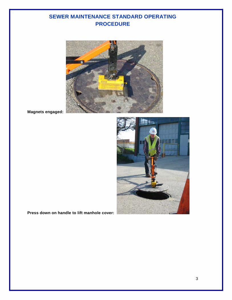
SEWER MAINTENANCE STANDARD OPERATING PROCEDURE
3
Magnets engaged:
Press down on handle to lift manhole cover:

SEWER MAINTENANCE STANDARD OPERATING PROCEDURE
Page 1 of 1
Administrative Support Field Operations
Area: Maintenance
Title: Monthly Test of CSO Monitoring Equipment
Status: Draft Final Original Date: 3/21/07 Revision Date: 4/21/10
Reviewers:
Author: R. Watts Revision Number 1
INTRODUCTION / PURPOSE:
To set a standard method for the monthly verification of CSO Rack monitoring equipment
SAFETY CONSIDERATIONS:
CSO Rack access is a permit required confined space entry. All confined space entry requirements must be met before entering.
All CSO Rack access requires a minimum of 2 Sewer Service Workers. Three or more may be required at road access points.
RESOURCE REQUIREMENTS:
Test plate (12’x12’ board), light, rope, radio, PPE, traffic cones and signs
PROCEDURE:
1. Complete all confined space entry requirements 2. One person enter CSO Rack and one remain outside 3. Take test plate into rack with you 4. Locate level transducer 5. Hold test plate under transducer
a. Plate must be held level and above the top of the weir wall b. This should trigger a rack overflow alarm received at the dispatch office
6. The person that remained outside will radio the dispatcher to verify the following a. The Rack Overflow alarm was received b. The level readout shows an increase c. The Total readout is showing a number greater than 0
7. Remove test plate and verify results (repeat test if unsure of results) 8. If all alarms and readouts were received and they reset after the plate was removed, complete
workorder and return to foreman 9. If there were problems with the dispatcher receiving any part of the test, note these items on
the workorder then call dispatcher to create a new workorder for the problem a. Be specific, no rack overflow alarm, no level change, no flow reading, communication
failure

SEWER MAINTENANCE STANDARD OPERATING PROCEDURE
Administrative Support Field Operations
Area: Maintenance
Title: Proper Manhole Inspection
Status: Draft Final Original Date: 2-22-06 Revision Date:
Reviewers:
Author: Soppi Revision Number: 0
INTRODUCTION/PURPOSE:
DETAILS:
Step 1. Locate the manhole and check the area around it for proper drainage away from the lid. The straight edge may be useful in this operation. With the straight edge, see that the hole (if located in a street) is at the proper elevation. In areas subject to snow, a high manhole ring or lid can cause the blades of snow removal equipment to catch on it, damaging both manhole and equipment. If the lid is excessively below or above the finished street grade, the manhole structure will be subject to pounding when traffic crosses it. These situations should be considered defects.
In easement areas, the manhole lid should be two or more inches above the soil level around it (except in driveways, walkways, or parking lots where street elevation requirements apply.)
Enter any grade or elevation defects on the report form.
Step 2. Test atmospheric conditions in the manhole by inserting the probe of gas detection device through an opening in the manhole cover.
Step 3. Safety: Manhole Entry
Remove the manhole lid (if atmospheric conditions are safe) and pull it to one side.
Mark the inspection form in accordance with the configuration of the pipes entering the manhole. Be sure to write neatly and clearly so others can read your writing and understand what you observed.
With the flashlight, inspect all surfaces and joints inside the manhole. Write on the form the location and types of any defects that may be observed, such as:
1. Cracks or breaks in the walls or bottom;
2. Infiltration at any place; estimate the flow in gallons per minute;
3. Joint security. Joints in a manhole should be tight. There should not be any visible cracks large enough to allow significant infiltration or exfiltration, or to harbor insects or vermin;
4. Offsets or misalignment of any parts;

SEWER MAINTENANCE STANDARD OPERATING PROCEDURE
5. Root intrusions;
6. Grease accumulations around arch or inside of sewers entering and leaving manhole;
7. Gravel or debris accumulations in invert;
8. Concrete or grout in the invert or pipe, causing flow turbulence;
9. Grout bed of frame;
10. Condition of steps or rungs;
11. Debris on shelf, steps, or rungs;
12. Sluggish flow or wastewater backing up into the manhole;
13. Corrosion.
Where there is minimal background noise, the inspector can squat and listen for the possible noise of turbulence or squirting water. Where the pounding of traffic has driven the manhole structure as little as a quarter of an inch below constructed grade, pipes connected to it can be cracked or broken at or near the connection point to the manhole. Infiltration or turbulence in the flow will sometimes make a detectable noise at those breaks. Look into the sewer piping upstream and downstream of the manhole for cracks or breaks that could have been caused by settling. Using a light or reflected sunlight to inspect a sewer between two adjacent manholes is known as “lamping.”
Step 4. With a wire brush and scraper, clean the ledge of the manhole ring. Inspect carefully for any cracks in the metal parts.
NOTE: ONE CRACK IN A MANHOLE RING WEAKENS THE REST OF THE METAL PART, THUS POSSIBLY RESULTING IN SUDDEN FAILURE UNDER A VEHICLE LOAD.
If a crack is observed, the manhole should be barricaded and the ring should be replaced immediately.
Step 5. Replace the manhole lid. Look for evidence of a warped or misfit lid by standing at various positions around the lid. The lid should not rattle or “rock.” When traffic passes over a lid with a rattle, the noise and rattle will increase with time. Make certain that the ring is clean and does not have a pebble or other object preventing proper fit before recording a rattle as a defect. A rocking or improperly seated manhole can be flipped completely out of the ring by a vehicle driving over the cover.
Defective manhole lids and rings can be removed and machined, milled in place with special equipment, or replaced. Rope ring may be used to reduce rattles, but rope ring has to be replaced periodically.

SEWER MAINTENANCE STANDARD OPERATING PROCEDURE
Administrative Support Field Operations
Area: Maintenance
Title: Root Cutter Accessory
Status: Draft Final Original Date: 8-31-05 Revision Date:
Reviewers: Hewitt, Soppi, Hahn, Aitken, Rhodes, Starcher
Author: Harbeson Revision Number: 0
INTRODUCTION/PURPOSE:
This SOP is created to provide the necessary steps, proper details, and prescribed precautions to properly operate the root cutter accessory.
DETAILS:
It is imperative that the internal working parts of the Root Cutter Motor itself are kept clean and free of foreign material such as sand, grit, rust, etc.
PRECAUTIONS:
1. Let the hydrant water run for a short period of time before hooking up to fill hose to minimize the possibility of rust and other particles from entering the water tank.
2. Keep the interior of the tank itself clear also with frequent maintenance checks because it is another possible source of troublesome particles.
3. Pour light duty oil at the threaded end of the motor (where the hose joins the unit). The shaft must turn in order to get the debris out of the motor and the oil into the motor. This procedure is easily performed by attaching a root cutter saw and gripping it with a pipe wrench to have more leverage in turning the shaft, thus properly distributing the oil inside the root cutter motor. The oil will soon discharge from the bypass tube at the bottom and rear of the motor unit. The shaft should now turn freely.
4. Turn the shaft three or four revolutions to be sure all of the water and grit is out of the motor.
5. To best protect your root cutter while not in use, pour the same type of oil again into the motor, turning the shaft at least four revolutions to be certain the oil has replaced all the water in the unit.
In operation, the root cutter functions like any cutting tool. The root cutter saw should spin freely; therefore, do not allow the jet propulsion to drive the cutter into the obstruction so fast that the hose has a tendency to kink. If the hose starts to kink, pull the hose back a few feet until the pressure is relieved; slowly let the cutter go ahead and the obstruction will be eliminated.
Prior to putting the root cutter into the pipe, it is recommended that you always start out with a saw two inches smaller than the pipe that is to be cleaned. For example, use a six-inch saw in an eight-inch pipe, or a 10-inch saw in a 12-inch pipe, etc. Do not use an eight-inch saw in an eight-inch pipe unless you are certain there are no misaligned pipes or offsets to hinder the cutting action of the saw.

SEWER MAINTENANCE STANDARD OPERATING PROCEDURE
Use the same size skid as you do the saw, such as an eight-inch skid and eight-inch saw. The skid will keep the saw in the middle of the pipe but requires slowing down your progress as the added weight and length of the skid assembly just can't move ahead as quickly as a plain jet nozzle.
It is preferable to run against the flow when using a root cutter. This is not a must, but it has a tendency to have the sewer water wash the debris away from the cutting saw so it can cut more efficiently.
When root cutters are new, they may bind up until they are broken in. This is generally caused by a piece of material or dirt that has gotten into the motor from the water tank. To remedy this problem, put soluble oil in the motor and turn the shaft until the oil comes out the bypass tube.
Always have the saw and root cutter started up the pipe before turning on the unit. Never have the water in the 'on' position or have the root cutter turning when it could come in contact with any personnel.
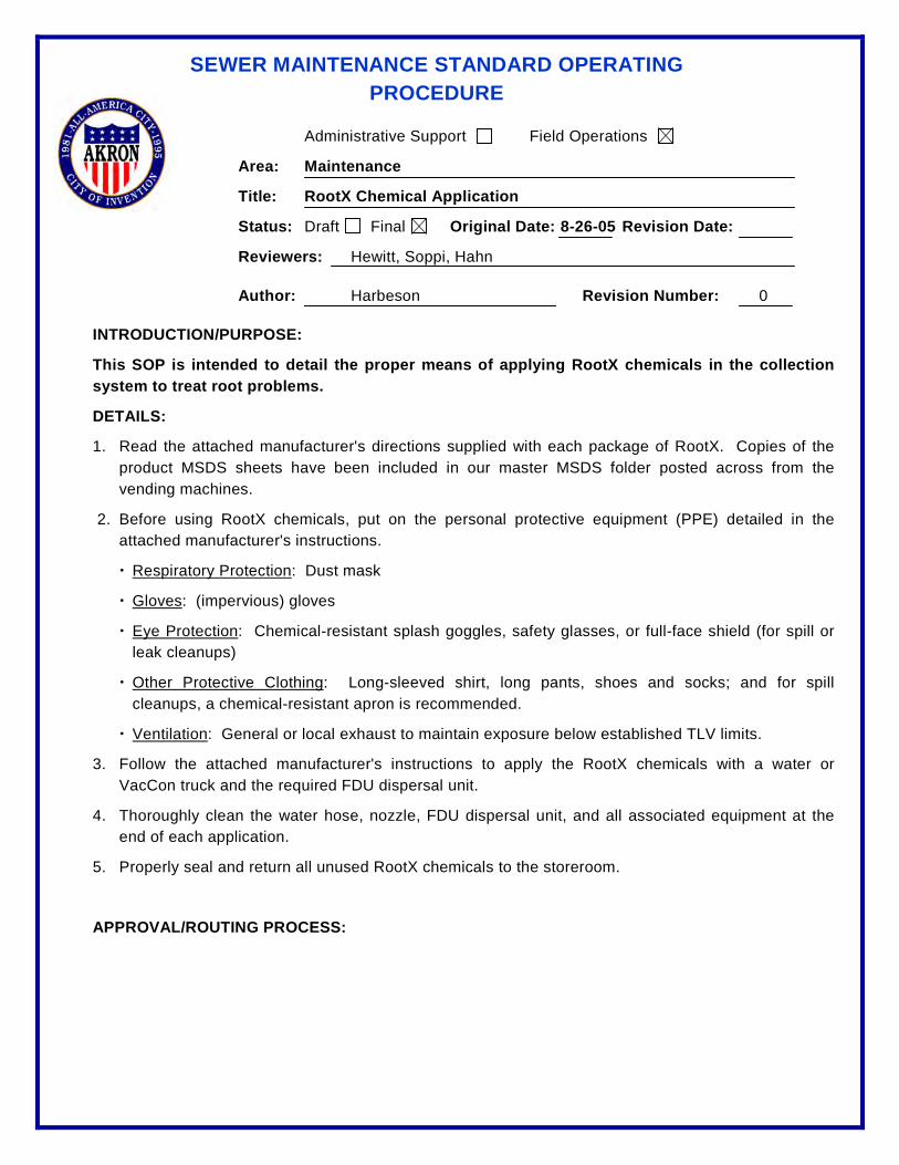
SEWER MAINTENANCE STANDARD OPERATING PROCEDURE
Administrative Support Field Operations
Area: Maintenance
Title: RootX Chemical Application
Status: Draft Final Original Date: 8-26-05 Revision Date:
Reviewers: Hewitt, Soppi, Hahn
Author: Harbeson Revision Number: 0
INTRODUCTION/PURPOSE:
This SOP is intended to detail the proper means of applying RootX chemicals in the collection system to treat root problems.
DETAILS:
1. Read the attached manufacturer's directions supplied with each package of RootX. Copies of the product MSDS sheets have been included in our master MSDS folder posted across from the vending machines.
2. Before using RootX chemicals, put on the personal protective equipment (PPE) detailed in the attached manufacturer's instructions.
Respiratory Protection
: Dust mask
Gloves
: (impervious) gloves
Eye Protection
: Chemical-resistant splash goggles, safety glasses, or full-face shield (for spill or leak cleanups)
Other Protective Clothing
: Long-sleeved shirt, long pants, shoes and socks; and for spill cleanups, a chemical-resistant apron is recommended.
Ventilation
3. Follow the attached manufacturer's instructions to apply the RootX chemicals with a water or VacCon truck and the required FDU dispersal unit.
: General or local exhaust to maintain exposure below established TLV limits.
4. Thoroughly clean the water hose, nozzle, FDU dispersal unit, and all associated equipment at the end of each application.
5. Properly seal and return all unused RootX chemicals to the storeroom.
APPROVAL/ROUTING PROCESS:
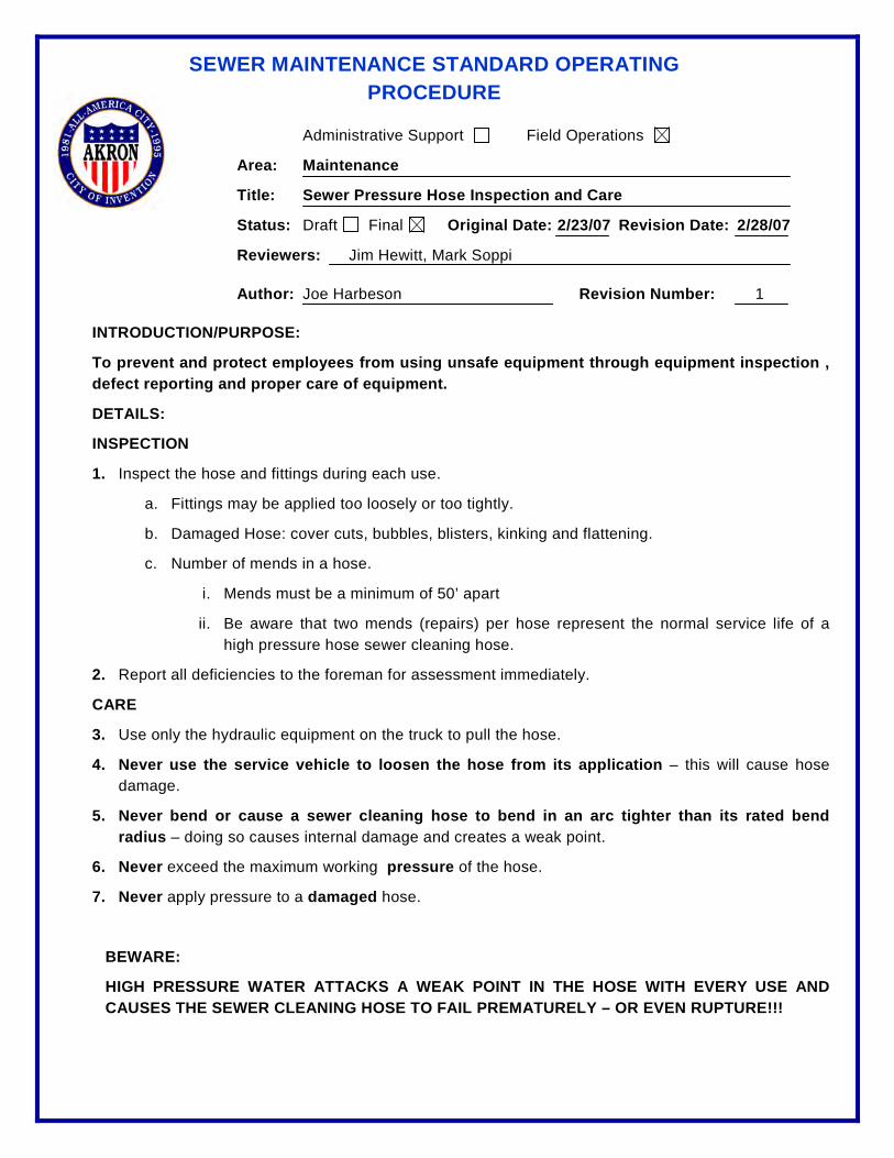
SEWER MAINTENANCE STANDARD OPERATING PROCEDURE
Administrative Support Field Operations
Area: Maintenance
Title: Sewer Pressure Hose Inspection and Care
Status: Draft Final Original Date: 2/23/07 Revision Date: 2/28/07
Reviewers: Jim Hewitt, Mark Soppi
Author: Joe Harbeson Revision Number: 1
INTRODUCTION/PURPOSE:
To prevent and protect employees from using unsafe equipment through equipment inspection , defect reporting and proper care of equipment.
DETAILS:
INSPECTION
1. Inspect the hose and fittings during each use.
a. Fittings may be applied too loosely or too tightly.
b. Damaged Hose: cover cuts, bubbles, blisters, kinking and flattening.
c. Number of mends in a hose.
i. Mends must be a minimum of 50’ apart
ii. Be aware that two mends (repairs) per hose represent the normal service life of a high pressure hose sewer cleaning hose.
2. Report all deficiencies to the foreman for assessment immediately.
CARE
3. Use only the hydraulic equipment on the truck to pull the hose.
4. Never use the service vehicle to loosen the hose from its application – this will cause hose damage.
5. Never bend or cause a sewer cleaning hose to bend in an arc tighter than its rated bend radius – doing so causes internal damage and creates a weak point.
6. Never exceed the maximum working pressure of the hose.
7. Never apply pressure to a damaged hose.
BEWARE:
HIGH PRESSURE WATER ATTACKS A WEAK POINT IN THE HOSE WITH EVERY USE AND CAUSES THE SEWER CLEANING HOSE TO FAIL PREMATURELY – OR EVEN RUPTURE!!!
SEWER MAINTENANCE STANDARD OPERATING PROCEDURE
Administrative Support Field Operations
Area: Maintenance
Title: Tracking of Condition Assessment Data - CCTV Inspection
Status: Draft Final Original Date: 4/19/10 Revision Date: 5/3/12
Reviewers: Hewitt, Scarlatelli
Author: Brown and Caldwell Revision Number: 1
INTRODUCTION/PURPOSE:
In response to the requirements of the 2009 Consent Decree, the City of Akron has embarked on a proactive inspection of the gravity sewer system. Defects found during the inspection are documented using NASSCO’s PACP coding system.
As defined in the Consent Decree, Attachment D, Paragraph 3. E (and Attachment C, Paragraph 2. I. ii and iii); the City of Akron is required to track the defects found during the proactive CCTV Inspection program, including “acute defects and a schedule to repair these defects”.
CCTV logs provide the condition data of the pipes inspected, and the Work Order system describes the activities performed to repair, rehabilitate or replace the pipe.
Based on these requirements, this SOP is developed to outline the steps necessary to review the inspection reports, determine repair needs and track the information for Semi-Annual Reporting.
DETAILS:
1. Completed CCTV Inspection logs will be forwarded to the CMOM Coordinator or designee, who will populate the “Semi-Annual Report Tracking Sheet” with the appropriate information.
2. The CMOM Coordinator will review all defects assigned a severity code of “5” to determine if these defects are considered “Acute”.
a. If a defect is considered “Acute”, the location will be forwarded to the Supervisor of the Construction crews, or AEB through a Work Order to address the defect within one year of discovery, as required by the Consent Decree. All repairs to “Acute” defects shall be expedited to reduce the likely hood of a catastrophic pipe failure and/or overflow from occurring.
b. Repair information, when completed, will be communicated back to the CMOM Coordinator to populate the “Semi-Annual Report Tracking Sheet” with the date the defect was repaired.
3. All non-acute defects will be reviewed with the Supervisor of Construction, AEB representatives or others to determine what method will be used to repair the defect, and whether a pipe with multiple defects should be included on the 5 Year CIP for rehabilitation or replacement. Additionally, the preliminary schedule for such repairs will be determined.

SEWER MAINTENANCE STANDARD OPERATING PROCEDURE
4. The CMOM Coordinator or designee will populate the Semi-Annual Reporting Tracking Sheet with the information determined under Step #4.
5. If O&M defects are found and are likely to result in a system blockage if the problem returns, the location will be forwarded to the Infor Administrator for inclusion on the Speed Rodder Route for scheduled cleaning until the defects are addressed.
SEWER MAINTENANCE STANDARD OPERATING PROCEDURE
Administrative Support Field Operations
Area: Maintenance
Title: Vac-Con Trucks 382 and 377
Status: Draft Final Original Date: 8-31-05 Revision Date:
Reviewers: Hewitt, Soppi, Hahn, Aitken, Rhodes, Starcher
Author: Harbeson, Soppi Revision Number: 0
INTRODUCTION/PURPOSE:
This SOP is created to provide the necessary steps, proper details, and prescribed precautions to properly operate the Vac-Con truck.
DETAILS:
Check Personal Protective Equipment: hard hat, hearing and eye protection, safety vest, raincoat, boots, gloves, hand cleaner
Pre-Trip Procedures
Check tools: nozzles, extension fittings, tiger tail, safety cones, manhole hook, pipe wrench, mirror, and flashlight
Perform pre-trip inspection per CDL requirements.
Clean suction strainer daily: remove screen and flush with water.
Lubricate the three
Lubricate the three fittings on the hydrostatic pump driveline (P.T.O.) weekly with multi-purpose grade 2 lithium base grease.
vacuum compressor fittings daily or every 8 hours with a high temperature lithium complex plus EP (Mobilith SHC 100) CAUTION: Do NOT over lubricate.
Check hydraulic oil tank daily or every 8 hours.
Inspect the hose. Any hose that is worn or damaged must be replaced immediately.
Check Vac-Con daily for loose nuts and bolts.
Put hydrant valve on hydrant. Close hydrant valve. Turn hydrant all the way on. Open the hydrant valve and flush hydrant. Turn hydrant valve off. Attach hose to hydrant valve. Fill tank with clean water. (Be sure the main tank drain valve is closed.)
Job Site Procedures
Turn water off when it appears at the top of the sight gauge tube.
Set up traffic safety zone.
Position the truck so that the front is facing upstream and the hose reel can be centered over the manhole.

SEWER MAINTENANCE STANDARD OPERATING PROCEDURE
Remove lock pin from reel on passenger side.
Prepare to open the hose reel.
Lift articulating hose reel/outrigger selector valve.
Use articulating hose reel/outrigger control valve to open reel to center of manhole, then put outrigger down.
Push articulating hose reel/outrigger selector valve down.
Use reel control valve and turn reel speed on.
Pay out only enough hose to insert tiger tail over hose and attach the extension pipe and nozzle.
Nozzle selection: If the sewer line is plugged, nozzles with a hole in the front are more effective; but if normal maintenance is being done, the use of a 30-degree nozzle, sand and sludge nozzle, or a combination nozzle is very effective.
Important: Always include a fin-type nozzle extension between the end of the hose and the nozzle. This extension minimizes the possibility of a nozzle going up a house service and helps keep the nozzle in the center of the pipe.
Insert plastic hose guide over hose. If nozzle attachments are too large for hose guide to pass over, insert hose guide over hose before installing nozzle attachments.
Remove manhole cover and lower sewer hose down into manhole.
Keep in mind that the hose and nozzle should be inserted in the line to be cleaned so the nozzle is running against the flow. Be certain the nozzle is at least two (2) feet up the sewer line and tiger tail is in place before you turn on the water. (Nozzles must be contained in a pipe or they can cause injury when in an open area.)
Secure tiger tail rope to hose reel cleat to prevent sewer hose from drawing tiger tail into sewer.
Most of the cleaning is accomplished when the nozzle is retracted; the water coming out of the nozzle as well as the normal flow will provide you with a cleaner line.
Activate the WATER CONTROL VALVE to the "on" position and water will come out of the nozzle.
Cleaning Procedures
Turn the PUMP CONTROL on.
Start back motor.
Toggle THROTTLE up to increase the engine speed to 2500 RPM.
Move the FORWARD/NEUTRAL/REVERSE reel control handle to the forward position and increase the reel speed with the variable speed control until you reach the desired speed that you wish the nozzle to travel.
Continue to pay out hose until the nozzle reaches the first manhole upstream. Partner will signal arrival of nozzle at upstream manhole.
Move the reel control handle to NEUTRAL.

SEWER MAINTENANCE STANDARD OPERATING PROCEDURE
Decrease the reel speed. (There is no rule of thumb how fast the nozzle should travel up the pipe, but the longer it takes, the more water you use. Remember most of the cleaning is done when you are pulling the nozzle back and that is when the hose should be retrieved at a slow rate.)
Place the reel control in REVERSE.
Adjust reel speed control so hose is retrieved slowly. This allows the cleaning action to take place.
Guide the hose back and forth across the reel.
The appearance of the black leader hose indicates the nozzle is close to the starting manhole. Move the reel control handle to NEUTRAL.
Decrease the throttle control to idle.
Turn back motor off.
Turn pump control off.
Turn water control off.
You may have to assist the nozzle extension finding its way back into the manhole by jiggling the tiger tail hose guide.
Once the nozzle is back in the manhole, put the reel control handle
Remove hose and tiger tail hose guide from manhole.
in reverse to raise the sewer hose and nozzle from the manhole up near the reel.
Replace manhole cover.
Put tools away.
Raise hose reel outrigger.
Articulate reel back to closed position. Put lock pin back in.
Note: When moving the truck from manhole to manhole, reel must be rotated closed with locking pin in place.
Pull vehicle out of traffic.
Pick up traffic control cones.
Hook up the sewer hose to the recirculating system by attaching the front end of the hose to the female swivel fitting located near the reel.
Cold Weather Operation Precautions
Activate the WATER CONTROL VALVE to the "on" position and water will come out of the nozzle.
Turn the PUMP CONTROL on.
Start back motor.
Toggle THROTTLE up to increase the engine speed to 1500 RPM.
SEWER MAINTENANCE STANDARD OPERATING PROCEDURE
Whenever involved with jet cleaning in sub-freezing temperatures, run a small amount of water through the hose to make sure there is not a partial ice blockage. (Warning: An ice blockage can cause the hose to vibrate and jump tremendously, making it capable of causing severe injuries.)
To avoid ice build up, always store the Vac-Con truck in a heated garage.
1. Drain all water from water tanks.
Procedure to Air Purge the Water System
2. Remove nozzle from rodder hose.
3. Start auxiliary engine.
4. Start truck chassis engine.
5. Turn top rodder hose control valve and bottom pump control valve on the front hose reel to the ON position.
6. Plug air line with female quick coupler into male quick coupler located below the ball valve.
7. Turn air purge valve on left side of water pump to the OPEN position.
8. Allow air to push water from hose.
9. When hose is free of water, rotate hose reel clockwise until all water is out.
10. CLOSE air purge valve and turn OFF bottom water pump control valve and top rodder hose control valve.
11. Remove handgun and plug from the handgun connection.
12. Turn ON handgun valve.
13. Turn ON bottom pump control valve.
14. OPEN air purge valve and wait for all water to be blown from handgun system.
15. Turn OFF bottom pump control valve.
16. Turn OFF handgun valve.
17. CLOSE air purge valve.
18. OPEN debris body flushout valve.
19. Turn ON bottom pump control valve.
20. OPEN air purge valve and wait for all water to be blown from debris body flushout system.
21. Turn OFF bottom pump control valve.
22. CLOSE debris body flushout valve.
23. CLOSE air purge valve.
24. OPEN all three valves on front of pump.
25. OPEN air purge valve and wait for all water to be blown out of pump.
SEWER MAINTENANCE STANDARD OPERATING PROCEDURE
26. CLOSE air purge valve.
27. Unplug air line from below air purge ball valve. (If this step is not done, damage to air brake system could occur.)
28. Shut OFF auxiliary engine.
29. Shut OFF truck chassis engine.
30. Remove drain caps from water system bulkhead fittings under bumper, curb side.
31. NOTE: Store unit with all the water system ball valves in the ON position.

SEWER MAINTENANCE STANDARD OPERATING PROCEDURE
Administrative Support Field Operations
Area: Maintenance
Title: Vacuum on Vac-Con Trucks
Status: Draft Final Original Date: Revision Date:
Reviewers: Hewitt, Soppi, Hahn, Aitken, Rhodes, Starcher
Author: Soppi Revision Number: 0
INTRODUCTION/PURPOSE:
DETAILS:
1. Start engine and set parking brake to engage hydraulic system.
2. Unlatch boom from boom support.
3. The joystick located on the curb side of the hose reel raises and lowers the boom. Push the detent button in the center of the joystick and lift up to raise boom, or push down to lower boom. Release the joystick and the boom action will stop. To move the boom to the right or left, push the detent button in the center of the joystick and push toward the cab of truck to rotate the boom to the curb side, pull the joystick toward the front to rotate the boom to the driver's side. The boom will rotate 90 degrees from center of truck in each direction.
4. The telescopic boom toggle switch is located at the control panel near the joystick control marked IN and OUT.
5. Hook suction tubes with Quick Clamps using suction tube with crown as bottom tube and lower in manhole or catch basin.
6. Turn vacuum breaker control on.
a.) Breaker control is located on the top of the hose reel control panel.
b.) With the vacuum breaker switch in the ON position, if the operator needs to stop the flow of air to dislodge any debris from the end of the air tube, he can just reach over and turn the vacuum breaker switch to the OFF position to stop the air flow. Then, turn the switch back to the ON position and continue vacuuming.
7. With engine at idle speed, engage stroking lever on hydrostatic pump.
a.) Slowly increase speed of blower with electronic throttle control located on the hose reel to an operating range of 5000-6000 RPM.
8. Vacuum manhole or inlet.
9. To stop the compressor, use electronic throttle control to decrease the RPM until engine reaches idle speed.
10. Lift tubes out and take apart and put on truck.

SEWER MAINTENANCE STANDARD OPERATING PROCEDURE
11. To store the boom for transporting the machine, do the following:
a.) Retract boom all the way in.
b.) Rotate boom over boom support bracket.
c.) Lower boom into boom support and guide hose onto lower bracket.
d.) Latch boom to boom support. NOTE: Never transport boom unless boom is latched in boom support.
12. Disengage the stroking lever on the hydrostatic pump.
13. Turn vacuum breaker off. Truck is now ready to transport.

SEWER MAINTENANCE STANDARD OPERATING PROCEDURE
Administrative Support Field Operations
Area: Equipment Maintenance
Title: Vehicle Check – Pre-Trip and Post-Trip
Status: Draft Final Original Date: Revision Date:
Reviewers: Hewitt
Author: Harbeson Revision Number: 0
INTRODUCTION/PURPOSE:
DETAILS:
All city vehicles are to be inspected daily, at the beginning and end of each shift.
Use the vehicle inspection checklist to check the vehicle for roadworthiness.
Use the PPE checklist to verify that you have all of your personal protective equipment with you.
Use the equipment checklist unique to the vehicle being driven to verify that the vehicle is properly stocked with the appropriate equipment.
SEWER MAINTENANCE STANDARD OPERATING PROCEDURE
Administrative Support Field Operations
Area: Maintenance
Title: Wash Down Spray Gun on Vac-Con Trucks
Status: Draft Final Original Date: Revision Date:
Reviewers: Hewitt, Soppi, Hahn, Aitken, Rhodes, Starcher
Author: Soppi Revision Number: 0
INTRODUCTION/PURPOSE:
DETAILS:
1. Make sure all power is turned off to the pump and there is no pressure in any part of the system. Examine all connections, making sure they are secure.
WASH DOWN SPRAY GUN (VAC-CON TRUCKS 382, 377)
2. Pull back locking collar on quick connect, push onto male quick connect fitting of wash down system. Release locking collar making sure that it locks into male fitting.
3. Holding the spray gun in a downward vertical position, pointed away from the body, familiarize yourself with the operation of the trigger lock.
4. Make sure trigger lock is in "locked" position. Do not operate spray gun if trigger lock is not operating properly.
5. Turn water on to spray gun.
6. Turn pump control on.
7. Start rear motor.
8. Operate handgun at idle speed only. (650 PSI)
9.
Safety Precautions
DO
10.
use a "two-handed" control of spray gun at all times. Grasp spray gun firmly with both hands, one hand on the gun and the other grasping the insulated extension.
DO
11.
adopt a secure body stance prior to and during spray operation to safely control the high reactionary force of this unit.
DO
12.
impress on other people in the spraying area the importance of obeying strict safety precautions for everyone's safety.
DO
13.
develop a habit of shutting off the power to the pump, relieving fluid pressure from gun and hose by actuating trigger until all fluid ceases to flow, and setting the trigger lock in the locked position before attempting to remove the tip, nozzle, gun or any part of the gun, or when gun is not in use.
DO check operation of trigger lock before each spray period. Trigger lock must hold the trigger to its forward position. (Adjust if necessary.)
SEWER MAINTENANCE STANDARD OPERATING PROCEDURE
14. DO
15.
check carefully and tighten threaded connections regularly. Make them secure and leak-proof.
DO
16.
keep gun clean and dry to allow for positive grip.
DO
use spray gun in a well-ventilated area and make sure spray gun is grounded properly when used in a possible explosive or inflammable environment.
17.
WARNINGS
DO NOT
18.
aim spray gun at any person or any part of the body. Fluids under high pressure can penetrate the skin.
DO NOT
19.
alter equipment in any manner; if repairs are necessary, use only genuine factory repair parts.
DO NOT
20.
exceed maximum operating pressure of the lowest rated accessory item with the wash down system, even though some of the accessories have a higher maximum pressure rating.
DO NOT
21.
leave equipment under pressure unattended at any time. Relieve pressure by shutting off power to pump and actuating trigger until all fluid ceases to flow, then position trigger lock to the "locked" position.
DO NOT
22.
use spray gun that has a damaged, perforated, or weakened fluid hose.
DO NOT
23.
use spray gun with a faulty or damaged trigger lock.
DO NOT
Spray Gun Disassembly
operate a spray gun if there are any leaks from the packings, fittings, hoses, etc. Fluids that are under high pressure can penetrate skin, cloth, etc., and cause serious injury.
24. Make sure pump is turned off.
25. Release all the pressure and liquid from the hose to spray gun by operating trigger until fluid ceases to flow.
26. Set trigger lock in locked position.
27. Remove spray gun and hose from machine by pulling back on locking collar and removing from male fitting.

SEWER MAINTENANCE STANDARD OPERATING PROCEDURE
Administrative Support Field Operations
Area: Maintenance
Title: Wash Down Spray Gun on Water Trucks
Status: Draft Final Original Date: 8-31-05 Revision Date:
Reviewers: Hewitt, Soppi, Hahn, Aitken, Rhodes, Starcher
Author: Harbeson Revision Number: 0
INTRODUCTION/PURPOSE:
This SOP is created to provide the necessary steps, proper details, and prescribed precautions to properly operate the wash down spray gun.
DETAILS:
1. Make sure all power is turned off to the pump and there is no pressure in any part of the system. Examine all connections, making sure they are secure.
2. Pull back locking collar on quick connect, push onto male quick connect fitting of wash down system. Release locking collar making sure that it locks into male fitting.
3. Holding the spray gun in a downward vertical position, pointed away from the body, familiarize yourself with the operation of the trigger lock.
4. Make sure trigger lock is in "locked" position. Do not operate spray gun if trigger lock is not operating properly.
5. Turn on pump to operate spray gun.
6.
Safety Precautions
DO
7.
use a "two-handed" control of spray gun at all times. Grasp spray gun firmly with both hands, one hand on the gun and the other grasping the insulated extension.
DO
8.
adopt a secure body stance prior to and during spray operation to safely control the high reactionary force of this unit.
DO
9.
impress on other people in the spraying area the importance of obeying strict safety precautions for everyone's safety.
DO
10.
develop a habit of shutting off the power to the pump, relieving fluid pressure from gun and hose by actuating trigger until all fluid ceases to flow, and setting the trigger lock in the locked position before attempting to remove the tip, nozzle, gun or any part of the gun, or when gun is not in use.
DO
11.
check operation of trigger lock before each spray period. Trigger lock must hold the trigger to its forward position. (Adjust if necessary.)
DO
12.
check carefully and tighten threaded connections regularly. Make them secure and leak-proof.
DO keep gun clean and dry to allow for positive grip.

SEWER MAINTENANCE STANDARD OPERATING PROCEDURE
13. DO use spray gun in a well-ventilated area and make sure spray gun is grounded properly when used in a possible explosive or inflammable environment.
14.
WARNINGS
DO NOT
15.
aim spray gun at any person or any part of the body. Fluids under high pressure can penetrate the skin.
DO NOT
16.
alter equipment in any manner; if repairs are necessary, use only genuine factory repair parts.
DO NOT
17.
exceed maximum operating pressure of the lowest rated accessory item with the wash down system, even though some of the accessories have a higher maximum pressure rating.
DO NOT
18.
leave equipment under pressure unattended at any time. Relieve pressure by shutting off power to pump and actuating trigger until all fluid ceases to flow, then position trigger lock to the "locked" position.
DO NOT
19.
use spray gun that has a damaged, perforated, or weakened fluid hose.
DO NOT
20.
use spray gun with a faulty or damaged trigger lock.
DO NOT
Spray Gun Disassembly
operate a spray gun if there are any leaks from the packings, fittings, hoses, etc. Fluids that are under high pressure can penetrate skin, cloth, etc., and cause serious injury.
21. Make sure pump is turned off.
22. Release all the pressure and liquid from the hose to spray gun by operating trigger until fluid ceases to flow.
23. Set trigger lock in locked position.
24. Remove spray gun and hose from machine by pulling back on locking collar and removing from male fitting.

SEWER MAINTENANCE STANDARD OPERATING PROCEDURE
Administrative Support Field Operations
Area: Maintenance
Title: Water Truck 334
Status: Draft Final Original Date: 8-31-05 Revision Date:
Reviewers: Hewitt, Soppi, Hahn, Aitken, Rhodes, Starcher
Author: Harbeson, Soppi Revision Number: 0
INTRODUCTION/PURPOSE:
This SOP is created to provide the necessary steps, proper details, and prescribed precautions to properly operate the Water Truck #334.
DETAILS:
Check Personal Protective Equipment: hard hat, hearing and eye protection, safety vest, raincoat, boots, gloves, hand cleaner
Pre-Trip Procedures
Check tools: nozzles, extension fittings, tiger tail, safety cones, manhole hook, pipe wrench, mirror, and flashlight
Perform pre-trip inspection per CDL requirements.
Clean suction strainer daily: remove screen and flush with water.
Lubricate the three fittings on the hydrostatic pump driveline (P.T.O.) weekly with multi-purpose grade 2 lithium base grease.
Check hydraulic oil tank daily or every 8 hours.
Inspect the hose. Any hose that is worn or damaged must be replaced immediately.
Put hydrant valve on hydrant. Close hydrant valve. Turn hydrant all the way on. Open the hydrant valve and flush hydrant. Turn hydrant valve off. Attach hose to hydrant valve. Fill tank with clean water. (Be sure the main tank drain valve is closed.)
Job Site Procedures
Turn water off when it appears at the top of the sight gauge tube.
Set up traffic safety zone.
Position the truck so that the front is facing upstream and the hose reel can be centered over the manhole.
Remove lock pin from reel on passenger side.
Prepare to open the hose reel.
Lift articulating hose reel/outrigger selector valve.

SEWER MAINTENANCE STANDARD OPERATING PROCEDURE
Use articulating hose reel/outrigger control valve to open reel to center of manhole, then put outrigger down.
Push articulating hose reel/outrigger selector valve down.
Use reel control valve and turn reel speed on.
Pay out only enough hose to insert tiger tail over hose and attach the extension pipe and nozzle.
Nozzle selection: If the sewer line is plugged, nozzles with a hole in the front are more effective; but if normal maintenance is being done, the use of a 30-degree nozzle, sand and sludge nozzle, or a combination nozzle is very effective.
Important: Always include a fin-type nozzle extension between the end of the hose and the nozzle. This extension minimizes the possibility of a nozzle going up a house service and helps keep the nozzle in the center of the pipe.
Remove manhole cover and lower sewer hose down into manhole.
Keep in mind that the hose and nozzle should be inserted in the line to be cleaned so the nozzle is running against the flow. Be certain the nozzle is at least two (2) feet up the sewer line and tiger tail is in place before you turn on the water. (Nozzles must be contained in a pipe or they can cause injury when in an open area.)
Secure tiger tail rope to hose reel cleat to prevent sewer hose from drawing tiger tail into sewer.
Most of the cleaning is accomplished when the nozzle is retracted; the water coming out of the nozzle as well as the normal flow will provide you with a cleaner line.
Activate the WATER CONTROL VALVE to the "on" position and water will come out of the nozzle.
Cleaning Procedures
Turn the PUMP CONTROL on.
Engage P.T.O. Turn throttle control on.
Toggle THROTTLE up to increase the engine speed to 2500 RPM.
Move the FORWARD/NEUTRAL/REVERSE reel control handle to the forward position and increase the reel speed with the variable speed control until you reach the desired speed that you wish the nozzle to travel.
Continue to pay out hose until the nozzle reaches the first manhole upstream. Partner will signal arrival of nozzle at upstream manhole.
Move the reel control handle to NEUTRAL.
Decrease the reel speed. (There is no rule of thumb how fast the nozzle should travel up the pipe, but the longer it takes, the more water you use. Remember most of the cleaning is done when you are pulling the nozzle back and that is when the hose should be retrieved at a slow rate.)
Place the reel control in REVERSE.
Adjust reel speed control so hose is retrieved slowly. This allows the cleaning action to take place.

SEWER MAINTENANCE STANDARD OPERATING PROCEDURE
Guide the hose back and forth across the reel.
The appearance of the black leader hose indicates the nozzle is close to the starting manhole. Move the reel control handle to NEUTRAL.
Decrease the throttle control to idle.
Disengage P.T.O.
Turn pump control off.
Turn water control off.
You may have to assist the nozzle extension finding its way back into the manhole by jiggling the tiger tail hose guide.
Once the nozzle is back in the manhole, put the reel control handle
Remove hose and tiger tail hose guide from manhole.
in reverse to raise the sewer hose and nozzle from the manhole up near the reel.
Replace manhole cover.
Put tools away.
Raise hose reel outrigger.
Articulate reel back to closed position. Put lock pin back in.
Note: When moving the truck from manhole to manhole, reel must be rotated closed with locking pin in place.
Pull vehicle out of traffic.
Pick up traffic control cones.
Hook up the sewer hose to the recirculating system by attaching the front end of the hose to the female swivel fitting located near the reel.
Cold Weather Operation Precautions
Activate the WATER CONTROL VALVE to the "on" position and water will come out of the nozzle.
Turn the PUMP CONTROL on.
Engage P.T.O.

SEWER MAINTENANCE STANDARD OPERATING PROCEDURE
1. Drain all water from water tanks.
Procedure to Air Purge the Water System
2. Remove nozzle from sewer hose.
3. Start truck chassis engine.
4. Turn top sewer hose control valve and bottom pump control valve on the front hose reel to the ON position.
5. Connect air line with female quick coupler to male quick coupler located below the ball valve at the water pump.
6. Turn air purge valve on left side of water pump to the OPEN position.
7. Allow air to push water from hose.
8. When hose is free of water, rotate hose reel clockwise until all water is out.
9 CLOSE air purge valve and turn OFF bottom water pump control valve and top sewer hose control valve.
10. Remove handgun and plug from the handgun connection.
11. Turn ON handgun valve.
12. Turn ON bottom pump control valve.
13. OPEN air purge valve and wait for all water to be blown from handgun system.
14. Turn OFF bottom pump control valve.
15. Turn OFF handgun valve.
16. CLOSE air purge valve.
17. Turn ON bottom pump control valve.
18. OPEN air purge valve and wait for all water to be blown from water system hoses.
19. Turn OFF bottom pump control valve.
20. CLOSE air purge valve.
21. OPEN drain valves at water pump.
22. OPEN air purge valve and wait for all water to be blown out of pump.
23. CLOSE air purge vavle.
24. Unplug air lin from below air purge ball valve. (If this step is not done, damage to air brake system could occur.)
25. Shut OFF truck chassis engine.
26. Remove drain caps from water system bulkhead fittings under bumper, curb side.
27. NOTE: Store unit with all the water system ball valves in the ON position.
CAUTION: Water freezes at 32 degrees F. If at all possible, try to store unit in an area above this temperature.
IF ABOVE PROCEDURE IS FOLLOWED, UNIT SHOULD BE FREE OF WATER.

SEWER MAINTENANCE STANDARD OPERATING PROCEDURE
1. Position the water pump control valve and the hose reel control valve on the front of the hose reel in the OFF position.
Handgun Operation
2. Start the truck engine and run at idle speed. Turn ON the water pump.
3. Remove the quick disconnect plug from the handgun connection.
4. Connect the female end of the handgun hose to the handgun, and connect the male end of the handgun hose to the handgun connection on the main frame.
5. Make sure the handgun trigger is in the OFF position.
6. To pressurize the handgun, turn ON the handgun system ball valve located on the front bumper curb side.
7. Turn the bottom pump control valve on the front of the hose reel to the ON position.
8. The pressure of the handgun system is set at 650 PSI at auxiliary engine idle speed.
NOTE: NEVER run the truck engine over idle speed while operating the handgun.
9. To depressurize the handgun system, turn OFF the bottom pump control valve first, then turn OFF the handgun ball valve.
SAFETY NOTE: NEVER point the handgun at, or in the direction of, another person while it is pressurized or personal injury could occur.
SEWER MAINTENANCE STANDARD OPERATING PROCEDURE
Administrative Support Field Operations
Area: Maintenance
Title: Water Truck 380
Status: Draft Final Original Date: 8-31-05 Revision Date:
Reviewers: Hewitt, Soppi, Hahn, Aitken, Rhodes, Starcher
Author: Harbeson, Soppi Revision Number: 0
INTRODUCTION/PURPOSE:
This SOP is created to provide the necessary steps, proper details, and prescribed precautions to properly operate the water truck.
DETAILS:
Check Personal Protective Equipment: hard hat, hearing and eye protection, safety vest, raincoat, boots, gloves, hand cleaner
Pre-Trip Procedures
Check tools: nozzles, extension fittings, tiger tail, safety cones, manhole hook, pipe wrench, mirror, and flashlight
Perform pre-trip inspection per CDL requirements.
Clean suction strainer daily: remove screen and flush with water (turn valve off first)
Lubricate the nine
Lubricate the
fittings weekly on the hose reel and hose reel guide. Service and Lubrication chart is attached.
three
Inspect the hose. Any hose that is worn or damaged must be replaced immediately.
fittings monthly on the hose reel bearing - ¼ turn stops through one complete rotation. CAUTION: Do NOT over lubricate. Service and Lubrication chart is attached.
Put hydrant valve on hydrant. Close hydrant valve. Turn hydrant all the way on. Open the hydrant valve and flush hydrant. Turn hydrant valve off. Attach hose to hydrant valve. Fill tank with clean water. (Be sure the main tank drain valve is closed.)
Job Site Procedures
Turn water off when it appears at the top of the sight gauge tube.
Set up traffic safety zone.
Position the truck so that the rear is facing upstream and the hose reel can be centered over the manhole.
Open up rear panel door. CAUTION: Be certain that the rear door panel is completely open.
Prepare to extend the hose reel.
SEWER MAINTENANCE STANDARD OPERATING PROCEDURE
Locate the "REEL IN/OUT CONTROL" on the rear control panel. Push the "REEL IN/OUT CONTROL" toggle-style switch to the upward position. Reel assembly will begin to move outward. Visually make sure it will clear the rear door panel. Release the "REEL LOCK PIN" and rotate the reel into the working position.
Engage the "FORWARD/NEUTRAL/REVERSE" control into the forward position on the hydraulic pressure valve and the hose reel will pay out the sewer hose. Pay out only enough hose to insert tiger tail over hose and attach the extension pipe and nozzle.
Nozzle selection: If the sewer line is plugged, nozzles with a hole in the front are more effective; but if normal maintenance is being done, the use of a 30-degree nozzle, sand and sludge nozzle, or a combination nozzle is very effective.
Important: Always include a fin-type nozzle extension between the end of the hose and the nozzle. This extension minimizes the possibility of a nozzle going up a house service and helps keep the nozzle in the center of the pipe.
Insert plastic hose guide over hose. If nozzle attachments are too large for hose guide to pass over, insert hose guide over hose before installing nozzle attachments.
Remove manhole cover and lower sewer hose down into manhole.
Keep in mind that the hose and nozzle should be inserted in the line to be cleaned so the nozzle is running against the flow. Be certain the nozzle is at least two (2) feet up the sewer line and tiger tail is in place before you turn on the water. (Nozzles must be contained in a pipe or they can cause injury when in an open area.)
Secure tiger tail rope to clevis on rear bumper to prevent sewer hose from drawing tiger tail into sewer.
Most of the cleaning is accomplished when the nozzle is retracted; the water coming out of the nozzle as well as the normal flow will provide you with a cleaner line.
Activate the WATER CONTROL VALVE to the "on" position and water will come out of the nozzle.
Cleaning Procedures
Engage PTO.
Turn the PUMP CONTROL knob out until it comes to the full open position. (This will increase the RPM of the water pump.)
Toggle THROTTLE up to increase the engine speed to 2500 RPM.
Move the FORWARD/NEUTRAL/REVERSE reel control handle to the forward position and increase the reel speed with the variable speed control until you reach the desired speed that you wish the nozzle to travel.
Continue to pay out hose until the nozzle reaches the first manhole upstream. Partner will signal arrival of nozzle at upstream manhole.
Move the reel control handle to NEUTRAL.
SEWER MAINTENANCE STANDARD OPERATING PROCEDURE
Decrease the reel speed. (There is no rule of thumb how fast the nozzle should travel up the pipe, but the longer it takes, the more water you use. Remember most of the cleaning is done when you are pulling the nozzle back and that is when the hose should be retrieved at a slow rate.)
Place the reel control in REVERSE.
Adjust reel speed control so hose is retrieved slowly. This allows the cleaning action to take place.
Guide the hose back and forth across the reel.
The appearance of the black leader hose indicates the nozzle is close to the starting manhole. Move the reel control handle to NEUTRAL.
Turn off the throttle control.
Disengage PTO.
Put the off-on WATER CONTROL valve in the off position.
You may have to assist the nozzle extension finding its way back into the manhole by jiggling the tiger tail hose guide.
Once the nozzle is back in the manhole, put the reel control handle
Remove hose and tiger tail hose guide from manhole.
in reverse to raise the sewer hose and nozzle from the manhole up near the reel.
Replace manhole cover.
Put tools away.
Before retracting hose reel, operator must visually make sure there is nothing blocking reel retraction. The roll-up door must be fully open and the hose must be properly stored on the reel.
Turn reel speed off. Reel should not rotate.
Rotate the reel to its stored position (side of reel facing rear of truck). Lock in place by releasing "REEL LOCK PIN" from locked out position.
Note: When moving the truck from manhole to manhole, reel must be retracted; however, it does not need to be rotated sideways.
On the control panel, push the "REEL IN/OUT CONTROL" toggle switch to the downward position. Reel assembly will begin to move inward.
Retract reel completely. Visually make sure there is room to close the door.
Close rear and side doors completely.
Pull vehicle out of traffic.
Pick up traffic control cones.
SEWER MAINTENANCE STANDARD OPERATING PROCEDURE
During sub-freezing temperatures, always be certain that the doors on the rear of the unit are closed so the heater used in conjunction with the hydrostatic drive can provide heat to the pump and surrounding areas.
Cold Weather Operation Precautions
Hook up the sewer hose to the recirculating system by attaching the front end of the hose to the female swivel fitting located near the reel, engage the pump control and PTO. This procedure will circulate water through the entire system.
Whenever involved with jet cleaning in sub-freezing temperatures, run a small amount of water through the hose to make sure there is not a partial ice blockage. (Warning: An ice blockage can cause the hose to vibrate and jump tremendously, making it capable of causing severe injuries.)
To avoid ice build up, always store the water truck in a heated garage.
NOTE: When the machine must be left exposed to sub-freezing temperatures, the entire water system must be drained. Procedures for draining are as follows:
1) Drain supply tank by opening valve located at the curb side of the machine.
2) Drain pump valve chamber by opening drain plugs.
3) With the water control valve in the "off" position, drain the sewer hose by injecting compressed air into the air fittings located near the rear compartment door. If compressed air is not available, remove the nozzle and nozzle extension. Then tie the end of the hose on the reel and rotate the reel in the reverse position until the water drains from the hose.
4) Drain the wash down gun and hose by opening the gun valve and stretching out the wash down hose.
5) Finally, run the pump for approximately 20 seconds. This removes any water that may be trapped in the pump. Water freezing in the pump will damage the pump.
OSHA Regulations
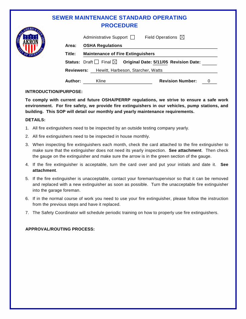
SEWER MAINTENANCE STANDARD OPERATING PROCEDURE
Administrative Support Field Operations
Area: OSHA Regulations
Title: Maintenance of Fire Extinguishers
Status: Draft Final Original Date: 5/11/05 Revision Date:
Reviewers: Hewitt, Harbeson, Starcher, Watts
Author: Kline Revision Number: 0
INTRODUCTION/PURPOSE:
To comply with current and future OSHA/PERRP regulations, we strive to ensure a safe work environment. For fire safety, we provide fire extinguishers in our vehicles, pump stations, and building. This SOP will detail our monthly and yearly maintenance requirements.
DETAILS:
1. All fire extinguishers need to be inspected by an outside testing company yearly.
2. All fire extinguishers need to be inspected in house monthly.
3. When inspecting fire extinguishers each month, check the card attached to the fire extinguisher to make sure that the extinguisher does not need its yearly inspection. See attachment. Then check the gauge on the extinguisher and make sure the arrow is in the green section of the gauge.
4. If the fire extinguisher is acceptable, turn the card over and put your initials and date it. See attachment.
5. If the fire extinguisher is unacceptable, contact your foreman/supervisor so that it can be removed and replaced with a new extinguisher as soon as possible. Turn the unacceptable fire extinguisher into the garage foreman.
6. If in the normal course of work you need to use your fire extinguisher, please follow the instruction from the previous steps and have it replaced.
7. The Safety Coordinator will schedule periodic training on how to properly use fire extinguishers.
APPROVAL/ROUTING PROCESS:

SEWER MAINTENANCE STANDARD OPERATING PROCEDURE
Administrative Support Field Operations
Area: OSHA Regulations
Title: Pre-Operation Checklist for Forklift Operation
Status: Draft Final Original Date: 5/11/05 Revision Date:
Reviewers: Hewitt, Harbeson, Starcher
Author: Kline Revision Number: 0
INTRODUCTION/PURPOSE:
To comply with current and future OSHA/PERRP regulations, we need to safely operate our equipment. Because of this, we have created a standard pre-trip checklist for the forklift that must be reviewed daily prior to use.
DETAILS:
1. Only personnel who are properly trained and licensed in forklift operation shall operate the forklift. If someone who is not licensed needs to load items that require the forklift, please ask one of the mechanics in the garage who are licensed to use the forklift to load the items.
2. Before each use of the forklift, the operator needs to perform the attached check list. There is a copy of the checklist attached on the forklift.
3. If there are any items on the checklist that does not pass inspection, notify the chief mechanic in the garage with any items that did not pass inspection.
APPROVAL/ROUTING PROCESS:

SEWER MAINTENANCE STANDARD OPERATING PROCEDURE
Administrative Support Field Operations
Area: OSHA Regulations
Title: Trench Safety
Status: Draft Final Original Date: Revision Date:
Reviewers: Hewitt
Author: Harbeson Revision Number: 0
INTRODUCTION/PURPOSE:
Our policy is based on the Federal OSHA Excavation Standard 29 CFR parts 1926.650-652 which has been adopted by the Ohio Division of Safety & Hygiene and applies to all Public Employees. This standard reads as follows:
DETAILS:
1926.652 (a) Protection of Employees in excavations:
(1) Each employee in an excavation shall be protected by an adequate protection system…except when: (i) Excavations are made entirely in stable rock; or
(ii) Excavations are less than five feet in depth.
Employees working in trenches four feet in depth or more shall have an adequate and safe means of exit, such as ladders, steps, or ramps available at no more than 25 feet of lateral travel.
Trenches more than five feet deep require shoring or must be laid back to a stable slope. In hazardous soil, trenches under five feet must be protected.
Specifications: (a) There is a minimum two feet setback from the edge of the excavation for the spoil pile. (b) The ladder must extend three feet above the excavation. c) Hard hat must be worn on construction site. The Sewer Maintenance Division’s policy is (and has been) to shore ALL excavations that exceed five feet in depth regardless of soil conditions. No variance is allowed for stable rock excavations. Sloping of excavations is permissible if approved by a properly trained worker, known as a “competent person” by the OSHA standards.
If there is a failure in a sheeting structure and a rescue is required, it is mandatory that on-site personnel immediately contact the Akron Fire Department.
Competent Person – one who is capable of identifying existing and predictable hazards in the surroundings which are unsanitary and or hazardous.
Training is required in three areas: Soils Analysis, Federal Regulations, Protective Equipment

Overtime
SEWER MAINTENANCE STANDARD OPERATING PROCEDURE
Administrative Support Field Operations
Area: Overtime
Title: Scheduling Overtime
Status: Draft Final Original Date: Revision Date:
Reviewers: Hewitt, Rhodes, Soppi, Watts
Author: Hewitt Revision Number: 0
INTRODUCTION/PURPOSE:
To ensure compliance with current and future EPA regulations, we need to maintain the daily flow of wastewater to WPCS. This includes responding to a variety of emergency situations during non-working hours. This SOP will detail how to schedule a crew to respond to an emergency situation.
DETAILS:
1. After being notified of an emergency situation, (i.e., odors, basement backups, flooded streets, street collapse, pump station alarm, rack overflow alarm, etc.), the dispatcher on duty will schedule the appropriate personnel to respond to the problem The attached overtime policy letter, dated January 31, 2005, details what overtime list to use, which class of employees to call, and how to charge them.
2. After scheduling the necessary crew, the dispatcher will unlock the facility gates and locate the necessary tools, parts, and equipment for the crew coming in to work the overtime
3. After the crew has been scheduled and the items in Step 2 accounted for, the dispatcher must:
a. E-mail the following individuals: • Jim Hewitt • Jim Aitken *NOTE: This list should also include Rick Watts • Bill Rhodes and Bob Wenker when the overtime • Mark Soppi involves a pump station. • Rose Cavett
b. This e-mail should include the following information: • Reason for overtime • Time crew was called in • Who was called in • Was the problem resolved
c. All overtime crews are required to fill out an overtime slip in accordance with our Departmental overtime SOP.
d. All overtime slips must be placed in the overtime slip box located in the dispatch office. e. To ensure timely payment, all overtime slips in the overtime box must be delivered by the
day shift dispatcher to the Payroll clerk by 8:00 am the following morning.
4. The day shift dispatcher is responsible for collecting the overtime sheets in the overtime sheet in-box and delivering them to the payroll clerk.

Payroll
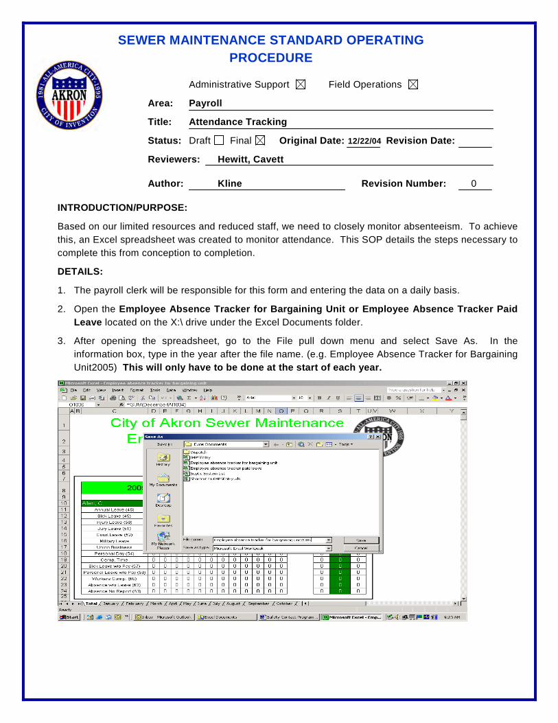
SEWER MAINTENANCE STANDARD OPERATING PROCEDURE
Administrative Support Field Operations
Area: Payroll
Title: Attendance Tracking
Status: Draft Final Original Date: 12/22/04 Revision Date:
Reviewers: Hewitt, Cavett
Author: Kline Revision Number: 0
INTRODUCTION/PURPOSE:
Based on our limited resources and reduced staff, we need to closely monitor absenteeism. To achieve this, an Excel spreadsheet was created to monitor attendance. This SOP details the steps necessary to complete this from conception to completion.
DETAILS:
1. The payroll clerk will be responsible for this form and entering the data on a daily basis.
2. Open the Employee Absence Tracker for Bargaining Unit or Employee Absence Tracker Paid Leave located on the X:\ drive under the Excel Documents folder.
3. After opening the spreadsheet, go to the File pull down menu and select Save As. In the information box, type in the year after the file name. (e.g. Employee Absence Tracker for Bargaining Unit2005) This will only have to be done at the start of each year.

SEWER MAINTENANCE STANDARD OPERATING PROCEDURE
4. At the beginning of each year, enter the total number of hours each employee has allotted for vacation, sick leave, personal days, and comp. time in the Total Allotted column on the Total Allotted column on the Total worksheet.
5. Select the monthly worksheet you want to enter information in.
6. Scroll down to find the employee you wish to enter information for.
7. Enter the number of hours in the proper description that the employee has taken off for that day.
8. To add additional employees to either spreadsheet, copy the whole block of cells from the last employee in the worksheet, and then paste the block of cells to the new employee. This process will have to be done on all 13 worksheets in the spreadsheets.
APPROVAL/ROUTING PROCESS:
On the first day of each month, e-mail a copy of both spreadsheets to the Superintendent.
At the mid-point of each grade period, please print out a hard copy of the Bargaining Unit members spreadsheet and give a copy to all foremen’s and supervisors.
At the mid-point of each grade period, please print out a hard copy of the paid leave and bargaining unit spreadsheets and give them to the Superintendent.

Pump Stations

SEWER MAINTENANCE STANDARD OPERATING PROCEDURE
Page 1 of 1
Administrative Support Field Operations
Area: Pump Stations
Title: Air Release System Inspection and Maintenance
Status: Draft Final Original Date: 7/10/07 Revision Date: 4/21/10
Reviewers:
Author: R. Watts Revision Number 1
INTRODUCTION / PURPOSE:
This SOP is prepared as a guide for inspecting the GORMAN-RUPP AIR RELEASE SYSTEM for proper operation.
SAFETY CONSIDERATIONS:
SPECIAL CONDITIONS:
RESOURCE REQUIREMENTS:
PROCEDURE:
1. Plunger Rod should open with pump off and close with pump primed and running. 2. Check for leaks (seals, diaphragm, pipes, fittings and hoses) 3. Check spring for damage or breaks. 4. Use a cotton swab or small brush to apply a liberal amount of water resistant grease
such as Lubriplate or Parker-o-lube on the plunger rod. Apply the lubricant through the spring to the visible part of the shaft while valve is in both the open and closed positions. In this manner the lubricant will be dragged through both seals during operation.
5. The valve is also equipped with grease fitting in the valve body. Add one shot of water resistant grease such as Lubriplate from a hand-operated grease gun through the grease fitting at regular intervals, or whenever the valve begins to stick or operate erratically.
6. FOR TROUBLE SHOOTING & REPAIRS see section C, D, E of your repair manual.

SEWER MAINTENANCE STANDARD OPERATING PROCEDURE
Page 1 of 1
Administrative Support Field Operations
Area: Pump Stations
Title: Alarm Response – Dry Well Flood
Status: Draft Final Original Date: 4/17/07 Revision Date: 4/21/10
Reviewers:
Author: R. Watts Revision Number 1
INTRODUCTION / PURPOSE:
To set the procedure for responding to a pump station Dry Well Flood alarm
SAFETY CONSIDERATIONS:
Turn off power to any flooded area, Never enter flooded area with power on (electrocution hazard), if flooding is to electric components notify foremen Before working on equipment Lock-out Tag-out
RESOURCE REQUIREMENTS:
PPE, paper coveralls, gloves, boots, face shield, paper mask
PROCEDURE:
1. Check station for leaks in pipes, pumps, seals, valves, packing etc.
2. Some possible causes to check for
a. Frozen water lines.
b. Sump pump not working (clogged, float stuck, debris built up in discharge pipe, no power
to pump)
c. Air Release line broken.
d. Packing or seal leaking
e. Check valve leaking at shaft arm
f. Sewage backing up conduit lines from wet well.
g. Sediment bowl leaking
h. Pressure relief valve leaking (Due to high pressure or defective valve)
3. Turn electrical power off to all wet electrical equipment.
4. Stop or isolate leaks by closing valves, turning water off, etc.
5. Repair leak as needed, add packing, tighten loose fittings, repair broken pipes, etc.
6. Dry equipment as needed and clean up station.
7. Reset breakers, controls, overloads, etc.
8. Return station to normal operation; make sure all alarms have cleared in dispatch office.

SEWER MAINTENANCE STANDARD OPERATING PROCEDURE
Page 1 of 2
Administrative Support Field Operations
Area: Pump Stations
Title: Alarm Response – Generator Fail, Power Outage
Status: Draft Final Original Date: 3/20/07 Revision Date: 4/21/10
Reviewers:
Author: R. Watts Revision Number 1
INTRODUCTION / PURPOSE:
To set a standard method for responding to Generator Fail alarm
SAFETY CONSIDERATIONS:
Watch for downed wires (stay away), call dispatcher to notify electric company Do not attempt to check or repair electrical components you have not been trained on If you smell natural gas do not enter or ventilate the pump station, call dispatcher to notify gas company, turn off gas at meter if possible
RESOURCE REQUIREMENTS:
Truck hand tools,
DETAILS / PROCEDURE:
1. Check problems with breaker on pole or check electric meter a. Look to see of fuse dropped down b. Look for obvious damage to wires or transformer c. Is meter working properly (wheel turning, light on, digital numbers lit)
2. Check for power inside pump station 3. Check generator alarm panel 4. If alarm is “High Engine Temp” check the following
a. Check for coolant leaks b. Check belts c. Check radiator for air flow circulation d. Check thermostat for correct operation
5. If alarm is “Low Oil Pressure” check the following a. Check oil pressure sender for proper operation (check with gauge) b. Check oil level c. Check for oil leaks
6. If alarm is “Engine Over Speed” check the following a. Try to reset b. Check manual c. Call Forman
7. If alarm is “Engine Over Crank” check the following
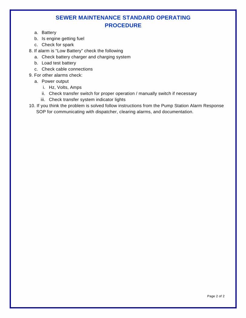
SEWER MAINTENANCE STANDARD OPERATING PROCEDURE
Page 2 of 2
a. Battery b. Is engine getting fuel c. Check for spark
8. If alarm is “Low Battery” check the following a. Check battery charger and charging system b. Load test battery c. Check cable connections
9. For other alarms check: a. Power output
i. Hz, Volts, Amps ii. Check transfer switch for proper operation / manually switch if necessary iii. Check transfer system indicator lights
10. If you think the problem is solved follow instructions from the Pump Station Alarm Response SOP for communicating with dispatcher, clearing alarms, and documentation.

SEWER MAINTENANCE STANDARD OPERATING PROCEDURE
Page 1 of 2
Administrative Support Field Operations
Area: Pump Stations
Title: Alarm Response – High Wet Well Alarm
Status: Draft Final Original Date: 4/10/07 Revision Date: 4/21/10
Reviewers:
Author: R. Watts Revision Number 1
INTRODUCTION / PURPOSE:
To set a standard method for response to a high wet well alarm condition
SAFETY CONSIDERATIONS:
If problem is electrical call electrician or foreman Confined space entry requirements must be met before entering wet well All high wet well alarm responses require 2 Pump Station personnel Follow LOTO procedures Allow pump to cool if overheated Check temperature before opening any covers, plates, or plugs Close suction and discharge valves before working on pump or check valve. Vent pump slowly and cautiously Drain the pump
RESOURCE REQUIREMENTS:
Required Tools, Confined space equipment, PPE,
PROCEDURE:
1. Verify that well is high 2. Check to see what other alarms are activated 3. Check station for power 4. Check to see if pumps are running
a. If running but not pumping check: i. To verify, look for well level to drop and check valve arms should open up when
running. ii. Pump lost prime iii. Couplings and belts iv. Clogs, jammed with debris v. Suction leak vi. Air release for proper operation
b. If not running check: i. Breakers, fuses and starter overloads ii. Bubbler system for correct operation

SEWER MAINTENANCE STANDARD OPERATING PROCEDURE
Page 2 of 2
iii. Motor for proper operation (burned up) iv. Condition of control panel v. For loose connections vi. Float operation
5. For additional information refer to maintenance manual

SEWER MAINTENANCE STANDARD OPERATING PROCEDURE
Page 1 of 1
Administrative Support Field Operations
Area: Pump Stations
Title: Alarm Response – Station Communication Fail
Status: Draft Final Original Date: 5/11/07 Revision Date: 4/21/10
Reviewers:
Author: R. Watts Revision Number 1
INTRODUCTION / PURPOSE:
To set a standard method for responding to Sewer Pump Station or CSO rack communication fail
SAFETY CONSIDERATIONS:
RESOURCE REQUIREMENTS:
DETAILS / PROCEDURE:
1. When alarm condition indicates communication failure, have the dispatcher try to update communication before proceeding to site
a. If alarm still does not clear pump station personnel should be called in this order, pump station foreman or electrician, if both are unavailable then pump station mechanic
2. On arrival at pump station, check the radio for power a. This is indicated by an LED display on the front of radio, if illuminated radio has power
3. If no LED indicating radio has no power a. Check that radio is on by turning volume knob clockwise b. Check the radio power supply LED is illuminated c. Check the radio fuses (2)
4. If the radio has power and still no communication reboot the radio a. Turn the radio volume control knob counter clockwise until it clicks off (LED display will
go dark) b. Turn radio back on after approximately 10 to 20 seconds c. Have dispatcher try to update communications, be sure to wait at least 2 minutes for
alarm to clear 5. If alarm still does not clear check the following for loose connections, damage, or other signs
of problems a. Antenna and antenna connections b. Connections at the radio and RTU
6. If at this point communication cannot be reestablished changing of major components may be necessary
7. Notify the dispatcher that the communication problems need to be addressed at a later time 8. Check the station and insure that all other station functions are working properly
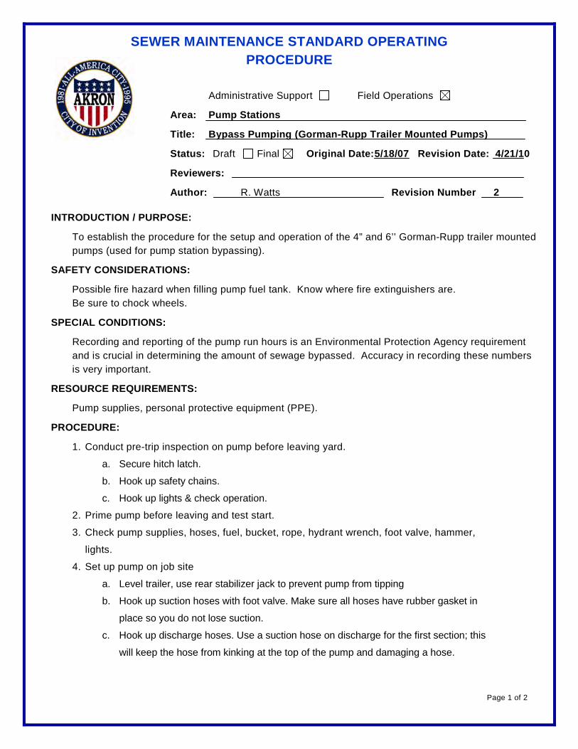
SEWER MAINTENANCE STANDARD OPERATING PROCEDURE
Page 1 of 2
Administrative Support Field Operations
Area: Pump Stations
Title: Bypass Pumping (Gorman-Rupp Trailer Mounted Pumps)
Status: Draft Final Original Date: 5/18/07 Revision Date: 4/21/10
Reviewers:
Author: R. Watts Revision Number 2
INTRODUCTION / PURPOSE:
To establish the procedure for the setup and operation of the 4” and 6’’ Gorman-Rupp trailer mounted pumps (used for pump station bypassing).
SAFETY CONSIDERATIONS:
Possible fire hazard when filling pump fuel tank. Know where fire extinguishers are. Be sure to chock wheels.
SPECIAL CONDITIONS:
Recording and reporting of the pump run hours is an Environmental Protection Agency requirement and is crucial in determining the amount of sewage bypassed. Accuracy in recording these numbers is very important.
RESOURCE REQUIREMENTS:
Pump supplies, personal protective equipment (PPE).
PROCEDURE:
1. Conduct pre-trip inspection on pump before leaving yard.
a. Secure hitch latch.
b. Hook up safety chains.
c. Hook up lights & check operation.
2. Prime pump before leaving and test start.
3. Check pump supplies, hoses, fuel, bucket, rope, hydrant wrench, foot valve, hammer,
lights.
4. Set up pump on job site
a. Level trailer, use rear stabilizer jack to prevent pump from tipping
b. Hook up suction hoses with foot valve. Make sure all hoses have rubber gasket in
place so you do not lose suction.
c. Hook up discharge hoses. Use a suction hose on discharge for the first section; this
will keep the hose from kinking at the top of the pump and damaging a hose.
SEWER MAINTENANCE STANDARD OPERATING PROCEDURE
Page 2 of 2
i. If station is equipped with bypass valve, hook up pump discharge to bypass
connection
ii. Open bypass connection valve and close the force main valve back to the
station.
d. Fill pump with water at filler cap. Put cap back on. (Do not over tighten cap. Over
tightening will cause cap to crack in half)
e. Open small bleeder valve on discharge elbow.
5. Very important - Record hour meter reading, along with date and time, before starting
pump. Record reading on your time sheet and call in reading to Dispatcher so he can
report to Ohio EPA.
6. Call Dispatcher and have Dispatcher report to Ohio EPA the proper information
according to the SOP for sewage spills etc.
a. The Ohio EPA must be notified verbally within 24 hours of any spills.
7. Start pump, run at full throttle. Watch bleeder for a steady stream of water.
a. After all air is bled out and pump is pumping, turn off bleeder.
b. Keep pump running at full throttle as long as needed but do not let it suck air causing
pump to lose prime or cavitate. Throttle down to idle and turn off. Before restarting
allow water to rise to a pumpable level.
c. Check oil, fuel, etc., every shift.
8. Very important - Record hour meter reading at the end of pumping job, date, and time.
Subtract that reading from the start reading to get total pump run hours. Report readings
to Dispatcher and record on your time sheet.
9. When done, drain pump at drain plug in bottom of volute.
10. Report any repairs needed to garage: leaky hose, lights out, engine not running properly,
etc.

SEWER MAINTENANCE STANDARD OPERATING PROCEDURE
Page 1 of 1
Administrative Support Field Operations
Area: Pump Stations
Title: Change Desiccant (Bubbler System)
Status: Draft Final Original Date: 5/17/07 Revision Date: 4/21/10
Reviewers:
Author: R. Watts Revision Number 1
INTRODUCTION / PURPOSE:
To set the procedure for replacing bubbler system desiccant
SAFETY CONSIDERATIONS:
Do not breathe dust or power from desiccant, use filter mask
RESOURCE REQUIREMENTS:
Face shield, Gloves, Clean rags, paper filter mask,Desiccant.
PROCEDURE:
1. Check desiccant weekly, if color has changed from blue to pink it needs replaced. 2. Turn power off to air compressors.
3. Turn pumps off.
4. Bleed off all air pressure in system. ( never allow high pressure to diaphragm, this could
damage them ) 5. Remove locking collar from desiccant canister and remove canister carefully.
6. Empty into trash container.
7. Wipe out container with clear dry rag. 8. Check o ring seal for damage and replace if necessary.
9. Fill container with 1 bag of desiccant.
10. Wipe any desiccant off from seal area. ( do not use any lubricant )
11. Install canister back in place making sure it is seated completely and lock ring locked completely.
12. Close bleeder.
13. Turn power back on to air compressors.
14. Check for air leaks. 15. Turn pumps back on automatic.
16. Check for any alarms and reset as needed.
17. Monitor station for normal operation.
SEWER MAINTENANCE STANDARD OPERATING PROCEDURE
Page 1 of 1
Administrative Support Field Operations
Area: Pump Stations
Title: Check and Adjust Belts
Status: Draft Final Original Date: 8/8/07 Revision Date: 4/21/10
Reviewers:
Author: R. Watts Revision Number 2
INTRODUCTION / PURPOSE: To supplement the Operation and Maintenance manuals with a non-technical document to aid in the inspection of drive belts.
SAFETY CONSIDERATIONS: Follow all safety procedures paying particular attention to Lock Out and Tag Out of all equipment and associated devices.
Do Not Operate Equipment Without Safety Guards
SPECIAL CONDITIONS: Check Maintenance Manual
Check repair manual for proper adjustment and or replacement.
RESOURCE REQUIREMENTS: Lock and tag Personal Protective Equipment Maintenance Manual Issued Tools
PROCEDURE:
1. LOTO – lock out tag out equipment
2. Inspect belts for cracks fraying or glazing, replace as needed.
3. In drive systems with 2 or more belts be sure they are always match sets. Unmatched
set will cause accelerated wear.
4. Inspect belt alignment. Check sheaves with straightedge. They must run parallel.
5. Shafts alignment and sheave alignment each is important for proper wear and
performance.
6. Check belt tension.
7. A clogged pump may cause belts to wear or break, check that equipment turns freely.
8. Be sure to install all safety guards or covers back in place properly.
9. Record work completed on time sheet.

SEWER MAINTENANCE STANDARD OPERATING PROCEDURE
Page 1 of 1
Administrative Support Field Operations
Area: Pump Stations
Title: Clean Wet Well
Status: Draft Final Original Date: 4/17/07 Revision Date: 4/21/10
Reviewers:
Author: R. Watts Revision Number 1
INTRODUCTION / PURPOSE:
To set a standard method for cleaning a wet well
SAFETY CONSIDERATIONS:
Confined space entry requirements must be met before entering wet well Have all necessary PPE All wet well cleaning requires 2 Pump Station personnel and VAC-Con crew Follow LOTO procedures
RESOURCE REQUIREMENTS:
VAC-Con truck & extra tubes if needed. Paper coveralls Gloves, boots, face shield, paper mask, respirator, hard hat
PROCEDURE:
1. Turn on ventilation blower before entering well 2. Close valve to air release where possible to help from getting clogged 3. Always clean floats and check that floats and sensors are properly fastened 4. Be careful not to damage bubbler line, conduit, sensors, floats, etc. 5. Remove grating for access and put back in place when done 6. Pump wet well as low as possible so you can clean bottom of well 7. Clean grease from walls 8. Check all pumps for prime 9. Check and clear all alarms 10. Open valve to air release when finished cleaning 11. Turn off ventilation blower 12. Once well is cleaned secure hatch 13. Check station for normal operation.

SEWER MAINTENANCE STANDARD OPERATING PROCEDURE
Page 1 of 1
Administrative Support Field Operations
Area: Pump Stations
Title: Cleve-Mass Rd Pump Station Chart Change Procedure
Status: Draft Final Original Date: 7/17/07 Revision Date: 4/21/10
Reviewers:
Author: Paul Cory Revision Number 2
INTRODUCTION / PURPOSE:
This SOP is prepared as a guide for changing the chart recorder at the Cleveland-Massillon Rd pump station facilities
SAFETY CONSIDERATIONS:
SPECIAL CONDITIONS:
Chart must be changed every 28 days. It should also be changed during the first week of every month.
RESOURCE REQUIREMENTS:
New replacement chart
PROCEDURE:
1. Change Chart a. Press “chart” button to stop recording. b. Lift up to raise the print arm off the chart. c. Write the date and current totalized value on the old chart. d. Remove the old chart. e. Put on a new chart with the writing on the chart facing out. f. Write the date and current totalized value on the new chart. g. Lower the print arm onto the chart. h. Press “chart” button to start recording.
2. Turn in the chart to Paul Cory. End of the month value will be added to the spreadsheet for the site and forwarded to Cheryl Atkins.
SEWER MAINTENANCE STANDARD OPERATING PROCEDURE
Page 1 of 2
Administrative Support Field Operations
Area: Pump Stations
Title: Electric Motor Lubrication
Status: Draft Final Original Date: 5/24/07 Revision Date: 4/21/10
Reviewers:
Author: D. Matthews / J. Kelly Revision Number 1
INTRODUCTION / PURPOSE: Establish standard procedures for the lubrication of typical electric motor bearing arrangements found in the sewer system. And to assist in the identification of typical motor bearing applications found in the system.
SAFETY CONSIDERATIONS: Be sure motor and associated equipment is Locked out tagged out Oil and grease spills will create slip and fall hazard (clean up)
SPECIAL CONDITIONS: When too much grease is applied, it is forced from the bearing housing and drips on the motor windings. The grease then attacks and destroys the insulation, resulting in early motor failure.
To prevent dirt making its way into the bearing, wipe the grease fittings and grease gun discharge clean before applying grease to a fitting.
Motor bearings typically will have one of several arrangements for lubrication. Many smaller motors have bearings that are sealed for the life of the bearing and no provision is made for re-greasing. Larger industrial motors will sometimes have a grease fitting plus a relief or drain plug. The drain plug is for purging the bearing of used grease. Many intermediate size motors will not have a drain plug; however, sometimes it is well hidden.
The fitting arrangements that typically exist are as follows: • bearing with a grease fitting (zerk) and a drain plug • bearing with a grease fitting and no drain plug • bearing with a grease fitting that incorporates a relief hole (no separate drain plug)
Remember, a hand-operated grease gun is capable of delivering over 5,000 PSI. That's enough pressure to blow the seals off any bearing. Pump grease to the bearing in small quantities!
RESOURCE REQUIREMENTS: Grease Gun loaded with appropriate grease Clean Rags, PPE

SEWER MAINTENANCE STANDARD OPERATING PROCEDURE
Page 2 of 2
PROCEDURE: Bearing with a grease fitting and a drain plug 1. Remove the drain plug. 2. Connect the grease gun to the fitting, and gently pump grease into the bearing until
fresh grease comes out of the relief hole. 3. Run the motor. Excess grease will come out of the hole. Continue to run until
pressure is relieved and no more grease comes out, usually about 20 to 30 minutes. 4. Replace the drain plug.
Bearing with a grease fitting and no drain plug 5. Connect the grease gun to the fitting and gently pump grease into the bearing. Pump
in a small quantity at a time, and wait. Stop if resistance is felt. 6. Disconnect the grease gun and remove the grease fitting. 7. Run the motor. Allow grease to come back out of the hole until pressure is relieved
and no more grease comes out. If, after removing the fitting, no grease comes out of the hole, the bearing was probably very dry to begin with. Repeat steps 1 and 2 until grease comes out of the hole when the fitting is removed.
8. Replace grease fitting.
Bearing with a relief fitting that incorporates a relief hole (no separate drain plug). 9. Connect the grease gun to the fitting and gently pump grease into the bearing until
grease comes out of the relief hole. 10. If grease does not come from the relief hole, the relief slot may be plugged. Inspect
and clean, or replace the fitting.
SEWER MAINTENANCE STANDARD OPERATING PROCEDURE
Page 1 of 1
Administrative Support Field Operations
Area: Pump Stations
Title: Generator and Auto-Start Service (Oil and Filter Change)
Status: Draft Final Original Date: 7/10/07 Revision Date: 4/21/10
Reviewers:
Author: R. Watts Revision Number 1
INTRODUCTION / PURPOSE: Establish standard procedures for Generator & Auto-Start Service, including oil and filter change for sewer pump stations emergency generators.
SAFETY CONSIDERATIONS: SPECIAL CONDITIONS:
Service engine annually or every 100 hours (prior to cold weather). Follow service manual for more detailed service instructions.
RESOURCE REQUIREMENTS: PROCEDURE:
1. Start engine to warm oil to operating temperature. 2. LOTO, Lock out and tag out Generator or Auto-start. 3. Drain Oil from drain plug. 4. Remove oil filter making sure old rubber gasket comes off with old filter. Lubricate
new rubber gasket with oil and install new oil filter. Hand tighten filter only. 5. Install drain plug and fill with proper amount of oil. (see manual for amount and
type of oil) 6. Check cooling system, test antifreeze must be good for -20 degrees below zero.
Change coolant every 2 years. Check that coolant is clean, change if needed. Check coolant for proper level. Check for leaks & condition of hoses, water pump, radiator, etc.
7. Check BLOCK HEATER making sure it is on and working properly. 8. Check and clean debris from radiator and inside & outside cabinet to insure proper
ventilation. 9. Check belts for wear and adjustment.(replace if needed) 10. Lubricate all linkage making sure it is free and not hitting anything. 11. Check oil level in governor. (see manual for detailed instructions) 12. Inspect & clean air filter, replace if needed. (Auto-start engine - Clean & change oil
in oil type air filters.) 13. Replace fuel filters. (diesel engines Mud Run, Lake of the Woods) 14. Check engine for miss, Tune Up if needed. (Spark plugs, wires, dist cap & rotor etc) 15. Check for corroded or loose wires and fittings. 16. Check PCV system. 17. Grease pillow block bearings on Auto-Start clutch shaft. 18. Check for loose bolts and nuts. 19. Dispose of oil and waste in proper place. Clean up work area. 20. Double check oil level after engine ran. Check for leaks. 21. Remove LOTO and put back on line. 22. RECORD Hours, Date & Parts on time sheet.
SEWER MAINTENANCE STANDARD OPERATING PROCEDURE
Page 1 of 1
Administrative Support Field Operations
Area: Pump Stations
Title: Pump Oil Change and Wear Plate Adjustment
Status: Draft Final Original Date: 7/17/07 Revision Date: 4/21/10
Reviewers:
Author: R. Watts Revision Number 2
INTRODUCTION / PURPOSE:
This SOP is prepared as a guide for the annual Gorman-Rupp T series pump service
SAFETY CONSIDERATIONS:
SPECIAL CONDITIONS:
Follow service manual for a more detailed service instructions
RESOURCE REQUIREMENTS:
PROCEDURE:
1. LOTO- Lock out tag out pump. 2. Close suction & discharge valves. 3. Remove drain plugs from under rotating assembly. Remove top vented fill plug caps
checking that vents are open. (Seal cavity & bearing cavity) 4. Check oil for signs off water or metal shavings. (Possible seal failure) Record
findings on time sheet. 5. After all oil has drained install plugs and fill with SAE-30 weight non-detergent oil.
Bearing cavity fill to center of sight glass and seal cavity fill completely. 6. Remove 4 bolts on rotating assembly. Pry assembly out just enough to remove
shims. 7. Install the 4 bolts tightening assembly evenly until impeller just starts to rub wear
plate. 8. Measure gap with filer gauge and add approximately .015 inch. 9. Remove 4 rotating assembly bolts; pry back assembly enough to get shims in. 10. Install the correct equal amounts of shims between rotating assembly and volute
housing to allow the .015 clearance between wear plate and impeller. Tighten bolts evenly.
11. Rotate shaft to make sure impeller is not hitting wear plate. 12. Inspect belts for wear and proper adjustment. Check sheaves for alignment. 13. Remove LOTO, OPEN VALVES AND PUT BACK ON LINE. Test run pump for noise
etc. 14. Record date, parts and comments on time sheet. If no adjustment was left, seal
failure etc. (this information is needed to schedule preventative maintenance on seal replacement, wear plate replacement etc.)
SEWER MAINTENANCE STANDARD OPERATING PROCEDURE
Page 1 of 4
Administrative Support Field Operations
Area: Pump Stations
Title: Pump Packing Procedures
Status: Draft Final Original Date: 10/20/04 Revision Date: 4/21/10
Reviewers:
Author: J. Kelly Revision Number 1
INTRODUCTION / PURPOSE: To supplement the Operation and Maintenance manuals with a non-technical document to aid in the adjustment and/or replacement of pump packing.
SAFETY CONSIDERATIONS: Check with personnel responsible for equipment to be sure it can be taken out of service for repairs.
Follow all safety procedures paying particular attention to Lock Out and Tag Out of all equipment and associated devices.
SPECIAL CONDITIONS: Check Pump Maintenance Manual
RESOURCE REQUIREMENTS: Lock and tag Personal Protective Equipment Maintenance Manual Packing and packing tools Issued Tools Solvent Fine emery cloth
PROCEDURE: Removal of Old Packing 1) When the packing is to be checked or changed, shut down the pump (Lock
Out). 2) Relieve the pressure on the suction and discharge lines. 3) Drain both the lines and the suction housing. 4) Shut off and disconnect the water flush arrangement, if applicable. With the
water flush line disconnected check to make sure the opening on the pump and line has not been reduced by rust or other debris.
5) Remove all other objects necessary to get to the packing gland. 6) Loosen and remove the packing gland adjustment nuts and slide the gland
away or remove it from the stuffing box. 7) Remove the old packing using two extractors, one on each side, and pull each
ring out evenly.

SEWER MAINTENANCE STANDARD OPERATING PROCEDURE
Page 2 of 4
8) The lantern ring (or lantern ring halves depending on the pump) can also be extracted in this manner.
9) Ensure that all packing has been removed from the stuffing box. 10) Inspect the surface of the shaft for wear or grooves. If the shaft/shaft sleeve
is worn, badly scored or grooved it should be replaced or repaired. 11) Clean any deposits on the shaft with a solvent or with a fine emery cloth.
Smooth any burs or nicks in the shaft area. Ensure that the stuffing box is totally free of debris.
Installation of New Packing: 1) Determine the proper packing size, type, and number of rings, for your pump. 2) If coil packing is used, cut one ring to accurate size with either a butt or
mitered joint (depending on pump manufacture). An accurate cut butt joint is superior to a poor fitting mitered joint. Fit the ring over the shaft to assure proper length. Then remove and cut all other rings to the first sample. When the rings are placed around the shaft, a tight joint should be formed.
3) Lubricate packing rings with a good grade of packing grease before installing. Install packing, one ring at a time, slipping and tapping it back into place. Rotate shaft by hand each time a ring is inserted to aid in seating. Packing end joints should be staggered. Most pump manufactures call for joints to be staggered either 90° or 180° to the adjacent ring of packing.
4) Push rings into the stuffing box. Ensure that each ring is properly seated by using packing tampers. The lantern ring/s should align with the tapped hole on the stuffing box or be aligned slightly toward the gland. The lantern ring/s can be checked for alignment by inserting a small rod through the water flush hole.
5) After the correct number of packing rings have been installed in front of and behind the lantern ring/s slide the packing gland forward to meet the packing. The gland adjustment nut should be tightened only hand tight. Apply equal pressure to each nut. Over-tightening the packing gland may result in premature packing failure and possible damage to the shaft and gland. Often one ring of packing will not fit into the stuffing box. This is because new packing compresses. The final ring can usually be added after the pump is started and the packing is seated. But, operating conditions vary so it is impossible to say when the last ring can be added. A regular check should be made to determine when the rest of the packing has sufficiently compressed so as to allow space for the final ring. Ensure the lantern ring is not forced out by of position by this process.
6) The gland followers should enter the packing box at least 1/8” to prevent rocking of the glands: they must not jam or touch the shaft.
7) After adjusting packing glands, turn the shaft by hand to be certain it rotates freely.
8) Connect the water flush arrangement if disconnected. 9) Open any valves that were closed, and close any valves that were open to
relieve pressure on the suction and discharge lines. 10) Adjust the amount of packing leakage - A packed stuffing box is designed to
control leakage, not stop it completely. Leakage is generally necessary to reduce friction and dissipate heat. The amount of leakage necessary will

SEWER MAINTENANCE STANDARD OPERATING PROCEDURE
Page 3 of 4
depend on the fluid pumped, the installation, pump, speed and type. Generally most pump manufactures recommend 1-2 drops per second after the packing has seated and adjusted to the operating temperature. Refer to the necessary manuals for proper pump packing and leakage.
11) Remove Lock Out Tag Out devices needed to start pump. 12) PACKING ADJUSTMENT, (Pump should not be running while adjusting
packing). Upon initial start-up of the pump, adjust the gland nuts for the correct leakage rate. Once the pump is in operation, the packing should be checked every 15 minutes for proper leakage rate. The packing nuts should be tightened 1/6th
13) Stop pump, Lock Out.
of a turn every 15 minutes until excess leakage has stopped. Packing will need this adjustment until it has seated itself to the contour of the stuffing box area and the pump had come up to operating temperature. Monitoring is required during this start up period to ensure that lubrication is not cut-off as the packing warms up and expands. If this occurs, the gland must be loosened to restore the leakage. The packing must not be allowed to run dry – even for short periods. Scoring of the shaft may result that will cause premature failure of the packing and will prevent proper sealing until a new sleeve is installed.
14) Install all other appurtenances that were removed in order to get to the packing gland. This also includes any missing or loose items that should have been removed such as nuts, bolts, guards etc.
15) Clean area and wipe down equipment. 16) Remove all Lock Out Tag Out devices. 17) Start up pump again checking for any obvious mechanical faults. 18) Stop pump, if no faults were found follow the appropriate SOP for work
completion. If faults were found follow the appropriate corrective action. 19) Let appropriate personnel know when pump is ready for service. 20) Complete (Fill out) work order.
Pump Packing Specifications Chicago Pumps 1) Adjust leakage to a slow steady weepage of fluid when the pump is operating. 2) Replaced all rings of packing when weepage can no longer be controlled by adjusting
the gland. The addition of a single ring to restore gland adjustment is not recommended.
Allis-Chalmers 1) Adjust leakage to 40-60 drops per minute after packing has seated and pump is at
operating temperature. 2) Insert 2 rings of the appropriate size packing (The standard stuffing box consists of
five rings of 1/2'” square packing impregnated with oil and graphite, a seal cage and horizontally-split gland) with the joints toward the upper side of the shaft and about a 90 degree angle from each preceding joint.
3) Insert the seal cage making sure it is located under the sealing water inlet. 4) Put 3 more packing rings on top of the seal cage ends 90 degrees apart.

SEWER MAINTENANCE STANDARD OPERATING PROCEDURE
Page 4 of 4
Fairbanks Morse 1) Adjust leakage to a flow from the gland to a stream about 1/8” diameter after
packing has seated and pump is at operating temperature. 2) Insert 2 rings of the appropriate size packing (The standard stuffing box consists of
five rings of 1/2” synthetic packing graphite impregnated, ring half water seals 2, and 2 glands half-interlocking)with ends staggered 180° apart.
3) Insert the water seal ring halves 4) Put 3 more packing rings (ends 180 degrees apart) on top of the water seal ring. 5) Lightly tighten the gland nuts, and then loosen them so they can be adjusted with
finger pressure to allow a small flow of liquid to lubricate the packing.
SEWER MAINTENANCE STANDARD OPERATING PROCEDURE
Administrative Support Field Operations
Area: Pump Stations
Title: Pump Station Alarm Response
Status: Draft Final Original Date: 7/6/05 Revision Date: 4/21/10
Reviewers: Hewitt
Author: Watts Revision Number: 1
INTRODUCTION/PURPOSE:
This SOP is created to provide the necessary steps to follow when responding to pump station alarms.
DETAILS:
1. To protect our citizens, pump station alarms must receive top priority. Therefore, once an alarm is received, the pump station crew must:
a. Record list of alarms reported from the dispatcher.
b. Record time and location.
2. Once at the location, record any other alarms or problems.
a. Check well level by visually looking at wet well.
3. Troubleshoot alarms and problems.
4. Correct alarms and problems, as needed.
5. Test repairs made.
a. Example: test run pump for noise or leaks, vibrations, tripping overload or breakers.
6. Report back to the dispatcher to make sure all alarms have cleared.
7. Report to the dispatcher when everything is back to normal and when leaving the station. The dispatcher will log this call so that the next shift dispatcher will know that work was performed at this station and the alarms were cleared.
8. If for some reason the problem cannot be repaired, report it to the foreman or supervisor at once, and keep the dispatcher informed as well.
a. After normal working hours (emergency call-ins), repair the station to the best extent possible.
b. If repairs cannot be made within the prescribed four hours of overtime, require extensive work, or need specialized parts, it may be okay to shut down a pump until the next normal working day as long as the overall pump station flow is maintained without any further damage or alarms. Inform Dispatcher before leaving the pump station. A couple of examples would be:
Broken pump shaft at Lake of the Woods.
Repairing a generator with a leaky water pump while commercial power is running.
SEWER MAINTENANCE STANDARD OPERATING PROCEDURE
c. If bypass pumping becomes necessary, follow the SOP for Bypass Pumping.
9. Report all information on proper time sheet.
a. Daily time sheet for normal hours.
b. Overtime time sheet for after hours.
10. Common sense, communication, and safety are key factors in helping everyone get their jobs done safely and completely.
APPROVAL/ROUTING PROCESS:

SEWER MAINTENANCE STANDARD OPERATING PROCEDURE
Page 1 of 1
Administrative Support Field Operations
Area: Pump Stations
Title: Replace Generator Block Heater
Status: Draft Final Original Date: 8/28/07 Revision Date: 4/21/10
Reviewers:
Author: R. Watts Revision Number 2
INTRODUCTION / PURPOSE: To supplement the Operation and Maintenance manuals with a non-technical document to aid in the replacement of the Generator Block Heater.
SAFETY CONSIDERATIONS: Follow all safety procedures paying particular attention to Lock Out and Tag Out of all equipment and associated devices.
SPECIAL CONDITIONS:
Coolant may be extremely hot use caution!
Check Maintenance Manual
Check repair manual for proper adjustment and or replacement.
RESOURCE REQUIREMENTS: Lock and tag Personal Protective Equipment Maintenance Manual Issued Tools
PROCEDURE:
1. LOTO - lock out power to block heater & generator. 2. Carefully check coolant temperature (allow to cool down if to hot) 3. Take off radiator cap to relieve pressure from radiator.
4. Put cap back on to help create a vacuum in the system. This will help slow down the coolant from leaking when hoses are removed
5. Disconnect power cord to heater.
6. Inspect hoses & coolant and replace as needed. 7. Clamp off hoses to block heater to help prevent loose of coolant. Place drain bucket under heater
and remove hoses.
8. Remove from mounting bracket and install new heater in bracket. 9. Plug in or hook up power cord to heater.
10. Install hoses and bleed all air out of block heater before turning power to heater back on. (turning on heater with air trapped in it will damage heater and hoses.)
11. Fill with coolant and run generator up to normal operating temperature.
12. Check for leaks. 13. Clean up area. 14. Return all switches to normal operation.
15. Make sure heater has power and is working. 16. Fill out time sheet.

SEWER MAINTENANCE STANDARD OPERATING PROCEDURE
Page 1 of 1
Administrative Support Field Operations
Area: Pump Stations
Title: Reporting Out of Service
Status: Draft Final Original Date:4/17/07 Revision Date:4/21/10
Reviewers:
Author: R. Watts Revision Number 1
INTRODUCTION / PURPOSE:
To set the procedure for communicating with foreman and dispatcher when and how to report yourself out of service
SAFETY CONSIDERATIONS:
RESOURCE REQUIREMENTS:
PROCEDURE:
1. In the event of any of the following (but not limited to), employees will inform their supervisor or foreman immediately if a situation or emergency occurs that prevents them from continuing their work
a. Truck broken down b. Sick or injured c. Emergency leave, etc. d. Union business e. Personal business
2. Employees will not go out of service for personal reasons unless permission is received from supervisor
3. In the event of a situation, employees must notify their immediate supervisor or foreman at once; this may be done in one of three ways
a. Call and speak to your supervisor directly b. Report to your supervisor in person c. Page and/or radio your supervisor and wait for a response
4. If none of these actions put you in contact with your supervisor, you should attempt to contact the text highest person in your divisional structure
5. If you cannot reach a supervisor, contact the division secretary or if the situation is an emergency, the service directors office

SEWER MAINTENANCE STANDARD OPERATING PROCEDURE
Page 1 of 1
Administrative Support Field Operations
Area: Pump Stations
Title: RTU Battery Testing and Replacement
Status: Draft Final Original Date: 5/16/07 Revision Date: 4/21/10
Reviewers:
Author: R. Watts Revision Number 1
INTRODUCTION / PURPOSE:
To set the procedure for RTU battery testing and replacement
SAFETY CONSIDERATIONS:
None
RESOURCE REQUIREMENTS:
Two replacement batteries (3 volt disk and 12 volt )
PROCEDURE:
1. Replace the memory 3 volt disc battery in the CPU with the power on.
a. Pull battery out with tab located on front of unit,
b. Make sure polarity is correct as indicated on holder, be sure battery slides in between
contacts
2. For the large 12 volt battery turn off the breaker to the RTU for 30 seconds
3. Watch the radio to see if it continues to operate off of the battery
a. If the radio remains on during the test the battery is OK and does not need replaced
b. If the radio looses power within the 30 seconds, it must be replaced
4. (how do you replace the battery instructions goes here)
5. Once battery is replaced turn power back on
6. (Does the new battery need to be tested?)

SEWER MAINTENANCE STANDARD OPERATING PROCEDURE
Administrative Support Field Operations
Area: Pump Stations
Title: Weekly Checklist for Checking Pump Stations
Status: Draft Final Original Date: Revision Date: 12/04/08
Reviewers: Hewitt, Aitken
Author: Watts, Kline Revision Number: 1
INTRODUCTION/PURPOSE:
This SOP is created to provide the necessary steps for preventative maintenance at each of the pump stations in our service area.
DETAILS: Each week the pump station mechanics shall perform the following checklist at all of the pump stations:
1. Foreman to check the SCADA System daily in the dispatch office for any alarms or any irregularities.
2. Pump Station mechanics are to check with foreman and dispatch staff for any pump station alarms at the start of their shift.
3. Pump Station Mechanics are to check their stations (North or South) respectively and thoroughly fill out the required checklists weekly for each station.
4. Check airflow indicator to ensure proper bubbler system airflow. Check back-up air pump. Clean as necessary.
5. Start each pump to verify proper operation.
6. Monitor station for leaks, noise, vibrations (pumps, motors, etc.)
7. Check oil levels in pumps.
8. Check belts for wear and tension.
9. Check sump pumps, blowers, and humidifiers.
10. Check air release valves and vent lines, and check valve and piping.
11. Clean racks.
12. Check for alarms and faults.
13. Check well level and gauge.
14. Physically start generator or auto start engine at each pump station to ensure proper operation.
15. Record the hour meter reading on all generators at each pump stations.\
16. Check heater.
17. Check building (door and hatch), roof, gutters, locks, fences, etc.
18. Check lights.

SEWER MAINTENANCE STANDARD OPERATING PROCEDURE
19. Check filters in Variable Frequency Drives (Mud Run, Sycamore Lane, Cormany, Kibler, Fairhill, and Fairlawn Knolls).
20. Add or adjust packing if needed.
21. Drain air tanks, condensation bowls, etc.
22. Check switches for proper position (alternator, etc.)
23. Check breaker panels for tripped breakers.
24. Record suction and discharge readings.
25. Clean up station and empty any trash.
26. Turn in completed checklist weekly to the pump station foreman.
27. Report any problems to the pump station foreman.