CITILED CLL020 lighting LED Datasheet 3K D 3D B ~1E 5Byy3D B 5K 5B 1E 3K D 3D B 5B 1E 5K 1E 3K D 3K...
8
CITILED CLL020 lighting LED Datasheet http://www.manuallib.com/citiled/cll020-lighting-led-datasheet.html The light-emitting diode of an LED package radiates light and heat according to the input power. However, the surface area of an LED package is quite small,and the package itself is expected to release little heat into the atmosphere.An external radiator such as a heat sink is thus required.The heat dissipation structure up to the connection portion of the external radiator uses mainly heat conduction. ManualLib.com collects and classifies the global product instrunction manuals to help users access anytime and anywhere, helping users make better use of products. http://www.manuallib.com
Transcript of CITILED CLL020 lighting LED Datasheet 3K D 3D B ~1E 5Byy3D B 5K 5B 1E 3K D 3D B 5B 1E 5K 1E 3K D 3K...

CITILED CLL020 lighting LED Datasheet http://www.manuallib.com/citiled/cll020-lighting-led-datasheet.html
The light-emitting diode of an LED package radiates light and heat according to the input power.However, the surface area of an LED package is quite small,and the package itself is expectedto release little heat into the atmosphere.An external radiator such as a heat sink is thusrequired.The heat dissipation structure up to the connection portion of the external radiator usesmainly heat conduction.
ManualLib.com collects and classifies the global productinstrunction manuals to help users access anytime andanywhere, helping users make better use of products.
http://www.manuallib.com
CITIZEN ELECTRONICS CO., LTD. shall not be liable for any disadvantages or damages resulting from the use of technical information or data included in this document or the impossibility of download and use, responsibility for the cause of lawsuit or any other damages or losses.
This technical information or data shall be provided ‘as is’ to users and CITIZEN ELECTRONICS CO., LTD. does not guarantee the absence of error or other defects in this technical information or data, conformance of this technical information or data to specific purpose, this technical information or data or its use will not infringe the rights of users or third parties or any other content.
CITIZEN ELECTRONICS CO., LTD. reserves the right to make changes to technical information or data without notification.
●
●
●
CITIZEN ELECTRONICS CO., LTD.
1-23-1, Kamikurechi, Fujiyoshida-shi, Yamanashi, 403-0001, Japan Tel. +81-555-23-4121 http://ce.citizen.co.jp
Information contained in this document such as sentences, photographs and images is subject to copyright, and is protected by law. Unless it is for “duplication for private use” or “quotation” under copyright law, any duplication or diversion of this information without permission of CITIZEN ELECTRONICS CO., LTD. is prohibited by law.
Requests / [email protected]
Website for LEDs for lightinghttp://ce.citizen.co.jp/lighting_led/jp/
Ref.CE-P1614 10/11
6 Copyright © 2010 CITIZEN ELECTRONICS CO., LTD. All Rights reserved.
■Figure-7 ( a ) Characteristic of heat sink surface area - junction temperature Tj ■Figure-7 ( b ) Characteristic of input power - junction temperature Tj
4-3. Simulation ( CLL020-1204A1 )
* Above data represents simulation values and is not guaranteed to represent actual measurement values. Evaluation and verification shall be conducted under the conditions of actual use.
CITIZEN ELECTRONICS CO., LTD.1-23-1, Kamikurechi, Fujiyoshida-shi, Yamanashi, 403-0001, Japan Tel. +81-555-23-4121 http://ce.citizen.co.jp
Ref.CE-P1614 10/11
For efficient thermal design
A simulation is an effective procedure with regard to the thermal design. Simulation results from when the package of CLL020-1204A1 was connected to the heat sink with a heat conductive sheet are shown in Fig.7 ( a ), ( b ).
Boundary conditionsEnvironmental conditions : Ta = 25°CAnalysis space : 300mm×300mm×(250+L)mmWall condition : Top=Open, Others=25°CHeat dispersion conditions : Natural convection
Model conditionsThermal conductire grease : 4.5W/m.KThickness of the heat conductive sheet : t=0.12mmMaterial of the heat sink : Aluminum ( Number of the fin : 6 )
Outline dimensions of the heat sink : W 64mm x H 40mm*Note : sectional area 1099mm2, Dimension“L” is variable
Thermal conductive grease
CLL020-1204A1
WL
( Variable )
H
Structure figure of analytical model
Tc point(Cathode)
Structure figure of analytical model
Tc point(Cathode)
40
75
60
70
65
55
50
45
Surface area of the heatsink
Junction temperature Tj
(℃)
(mm2)
70
60
50
100
90
80
40
30
20
10
0
Junction Temperature Tj
Input power
0 105 20 2515
S = 200,000mm2
(℃)
(W)
Input Power : 8.8W
0 50,000 100,000 300,000200,000 250,000150,000
Heat Dissipation DesignCLL020 Series
5 Copyright © 2010 CITIZEN ELECTRONICS CO., LTD. All Rights reserved.
■Figure-6 ( a ) Characteristic of heat sink surface area - junction temperature Tj ■Figure-6 ( b ) Characteristic of input power - junction temperature Tj
4-2. Simulation ( CLL020-1203A1 )
* Above data represents simulation values and is not guaranteed to represent actual measurement values. Evaluation and verification shall be conducted under the conditions of actual use.
CITIZEN ELECTRONICS CO., LTD.1-23-1, Kamikurechi, Fujiyoshida-shi, Yamanashi, 403-0001, Japan Tel. +81-555-23-4121 http://ce.citizen.co.jp
Ref.CE-P1614 10/11
For efficient thermal design
A simulation is an effective procedure with regard to the thermal design. Simulation results from when the package of CLL020-1203A1 was connected to the heat sink with a heat conductive sheet are shown in Fig.6 ( a ), ( b ).
Boundary conditionsEnvironmental conditions : Ta = 25°CAnalysis space : 300mm×300mm×(250+L)mmWall condition : Top=Open, Others=25°CHeat dispersion conditions : Natural convection
Model conditionsThermal conductire grease : 4.5W/m.KThickness of the heat conductive sheet : t=0.12mmMaterial of the heat sink : Aluminum ( Number of the fin : 6 )
Outline dimensions of the heat sink : W 64mm x H 40mm*Note : sectional area 1099mm2, Dimension“L” is variable
Thermal conductive grease
CLL020-1203A1
WL
( Variable )
H
Structure figure of analytical model
Tc point(Cathode)
Structure figure of analytical model
Tc point(Cathode)
40
70
65
60
55
50
45
Surface area of the heatsink
Junction temperature Tj
(℃)
(mm2)
80
70
60
90
30
50
40
20
10
0
Junction Temperature Tj
Input power
0 105 2015
(℃)
(W)
S = 200,000mm2
Input Power : 6.6W
0 50,000 100,000 300,000200,000 250,000150,000
Heat Dissipation DesignCLL020 Series
4 Copyright © 2010 CITIZEN ELECTRONICS CO., LTD. All Rights reserved.
■Figure-5 ( a ) Characteristic of heat sink surface area - junction temperature Tj ■Figure-5 ( b ) Characteristic of input power - junction temperature Tj
4-1. Simulation ( CLL020-1202A1 )
* Above data represents simulation values and is not guaranteed to represent actual measurement values. Evaluation and verification shall be conducted under the conditions of actual use.
CITIZEN ELECTRONICS CO., LTD.1-23-1, Kamikurechi, Fujiyoshida-shi, Yamanashi, 403-0001, Japan Tel. +81-555-23-4121 http://ce.citizen.co.jp
Ref.CE-P1614 10/11
For efficient thermal design
A simulation is an effective procedure with regard to the thermal design. Simulation results from when the package of CLL020-1202A1 was connected to the heat sink with a heat conductive sheet are shown in Fig.5 ( a ), ( b ).
Boundary conditionsEnvironmental conditions : Ta = 25°CAnalysis space : 300mm×300mm×(250+L)mmWall condition : Top=Open, Others=25°CHeat dispersion conditions : Natural convection
Model conditionsThermal conductire grease : 4.5W/m.KThickness of the heat conductive sheet : t=0.12mmMaterial of the heat sink : Aluminum ( Number of the fin : 6 )
Outline dimensions of the heat sink : W 64mm x H 40mm*Note : sectional area 1099mm2, Dimension“L” is variable
Thermal conductive grease
CLL020-1202A1
WL
( Variable )
H
Structure figure of analytical model
Tc point(Cathode)
Structure figure of analytical model
Tc point(Cathode)
40
60
58
56
54
52
50
48
46
44
42
0 50,000 100,000 300,000200,000 250,000150,000
Surface area of the heatsink
Junction temperature Tj
(℃)
(mm2)
60
40
10
80
70
50
30
20
0
Junction Temperature Tj
Input power
0 42 8 12106
(℃)
(W)
Input Power : 4.4W
S = 200,000mm2
Heat Dissipation DesignCLL020 Series
■Figure-2
3 Copyright © 2010 CITIZEN ELECTRONICS CO., LTD. All Rights reserved.
Ta-Rc-a ( CLL020-1202 A1 ) ■Figure-3 Ta-Rc-a ( CLL020-1203 A1 )
3. Thermal design of the outside the packagePoint of the external heat dissipation mechanism
The thermal resistance outside the package Rc-a [°C/W], which is the combination of the heat-dissipation grease ( adhesive ) and the heat sink, is limited by the input power Pd [W], the ambient temperature Ta [°C], and the thermal resistance of the package Rj-c [°C/W], i.e.,
Tj function converted from the above formula is
and it is a straight line with the slope of -1 / Pd and the intercept of Tj / Pd - Rj-c.Figure-2 is the chart showing the relationship between the ambient temperature Ta and the thermal resistance outside the package Rc-a indicated by driving current, where Tj is assumed to be 150°C - the absolute maxi-mum rating value in the specifications for the
CLL020-0305A1 package.The higher the ambient temperature Ta and the larger the driving current, the smaller the allowable thermal resistance outside the package Rc-a = Rb + Rh.In brief, the grease ( adhesive ) and the heat sink, with smaller thermal resistance ( this means better heat dissipation ) , are required in order to keep Tj from exceeding 150°C, the absolute maximum rating in the specifications, if the ambient temperature becomes higher and/or the driving current is larger. Therefore, use Figure-2 as a guide when selecting the external heat dissipation parts, and ultimately conduct thermal verification on actual devices.The equivalent charts for the CLL020-1203A1, and CLL020-1204A1 packages are shown in Figure-3 and Figure-4, respectively.
Use the correlation between the thermal resistance and the ambient temperature for design of the external heat dissipation mechanism
CITIZEN ELECTRONICS CO., LTD.1-23-1, Kamikurechi, Fujiyoshida-shi, Yamanashi, 403-0001, Japan Tel. +81-555-23-4121 http://ce.citizen.co.jp
Ref.CE-P1614 10/11
Tj = ( Rj-c + Rc-a )・ Pd + Ta Rc-a = ( Tj - Ta ) / Pd - Rj-c
Rc-a = -Ta / Pd + Tj / Pd - Rj-c
60
50
40
30
10
20
00 10 20 30 40 7050 60 80
Rj-c=3.7(℃/W)
(℃)
240mA180mA
120mA80mA
Ta
Rc-a
(℃/W) 40
30
20
10
00 10 60 7020 30 40 50 80
Rj-c=2.6(℃/W)
(℃)Ta
Rc-a
(℃/W)360mA270mA
180mA120mA
30
15
20
25
10
5
00 6020 40 80
Rj-c=2.1(℃/W)
(℃)Ta
Rc-a
(℃/W)480mA360mA
240mA160mA
■Figure-4 Ta-Rc-a ( CLL020-1204 A1 )
Heat Dissipation DesignCLL020 Series
2 Copyright © 2010 CITIZEN ELECTRONICS CO., LTD. All Rights reserved.
Heat Dissipation Design
The cross-sectional structure example, where the package of the CLL020 series is connected to an external heat sink, is shown in Figure-1 ( a ). The package has a laminated structure of an aluminum substrate, insulating layers and conductive copper foil patterns.A distinctive point is that the light-emitting diode is mounted directly on the well conductive aluminum substrate not on the insulating layer, which has low thermal conductivity. Thus, the heat generated at the light-emitting diode can be efficiently conducted to the outside of the package.The aluminum substrate side of the package outer shell is thermally connected to the heat sink via heat-dissipation grease ( or adhesive ). As described above, the heat generated in the junction section of the light-emitting diode is transferred mainly to the heat sink using heat conduction, through the light-emitting diode to the adhesive for die-mounting to the aluminum
Understanding the junction temperature
substrate to the grease ( adhesive ). The thermal resistance between the junction section of the light-emitting diode and the aluminum substrate side of the package outer shell is Rj-c, and the specific thermal resistance value of the package. Therefore, the following formula is used
In addition, the thermal resistance of the grease ( adhesive ) outside the package is Rb [°C/W], the thermal resistance with the heat sink is Rh [°C/W], and the ambient temperature is Ta [°C].Figure-2 ( b ) indicates the equivalent thermal resistance along the cross-sectional diagram in Figure-2 ( a ). As indicated, the thermal resistances Rj-c, Rb, and Rh are connected in series between the junction temperature Tj and the ambient temperature Ta. The thermal resistances outside the package Rb and Rh can be integrated into the thermal resistance Rc-a at this point.Thus, the following formula is also used:
■Figure-2 ( a )Thermal Resistance Connection
■Figure-1 ( a ) Cross Section
1. IntroductionSignificance of the heat dissipation structureThe light-emitting diode of an LED package radiates light and heat according to the input power. However, the surface area of an LED package is quite small, and the package itself is expected to release little heat into the atmosphere. An external radiator such as a heat sink is thus required. The heat dissipation structure up to the connection portion of the external radiator uses mainly heat conduction.Regarding LED packages, to control the junction tempera-ture of the light-emitting diode Tj is important. The Tj must be kept from exceeding the absolute maximum rating in the specifications under any conditions. As direct measure-ment of the junction temperature of a light-emitting diode
inside a package is difficult, the temperature of a particular part on the external package ( the case temperature ) Tc [°C] is normally measured. Tj [°C] is calculated using the thermal resistance between the junction and the case Rj-c [°C/W], and the emitted heat amount that is nearly equal to the input power Pd [W]. The heat generated at the light-emitting diode can be conducted to the external radiator efficiently because the package structure for the CLL020 series minimizes the thermal resistance Rj-c.This document describes the detailed heat dissipation structure of the CLL020 series and provides data necessary for thermal design of the lighting apparatus to maximize LED performance.
2. Package structure and thermal resistance
CITIZEN ELECTRONICS CO., LTD.1-23-1, Kamikurechi, Fujiyoshida-shi, Yamanashi, 403-0001, Japan Tel. +81-555-23-4121 http://ce.citizen.co.jp
Heat dissipation structure that can conduct heat radiated from LEDs efficiently
Ref.CE-P1614 10/11
Tj = ( Rj-c + Rc-a ) ・ Pd + Ta
Tj = Rj-c ・ Pd + Tc
Tc
Tj Tj
TcRj-c Rj-c
Rc-aRb
Rh
Ta Ta
Heat Sink
BondAluminum
Cross-section diagram LED die Tj
TcRj-c
Rb
Rh
Ta
CLL020 Series
Ref.CE-P1614 10/11
1.2.3.4-1.4-2.4-3.
CONTENTSIntroduction
Package structure and thermal resistance
Thermal design outside the package
Simulation ( CLL020-1202A1 )
Simulation ( CLL020-1203A1 )
Simulation ( CLL020-1204A1 )
CLL020 Series
CITIZEN ELECTRONICS CO., LTD.
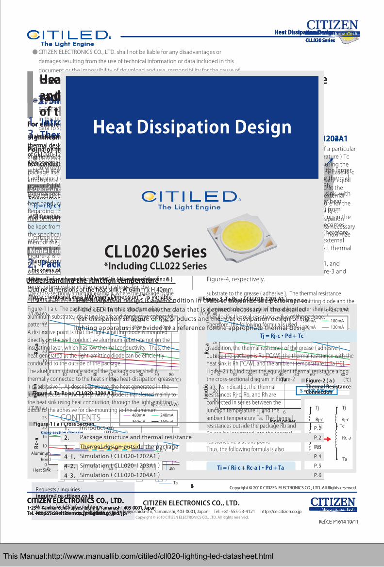
Heat dissipation design is a precondition in order to maximize the performance of the LED. In this document, the data that is deemed necessary in the detailed heat dissipation structure of the products and the heat dissipation design of the lighting apparatus is provided as a reference for the appropriate thermal design.
Heat Dissipation Design
1-23-1, Kamikurechi, Fujiyoshida-shi, Yamanashi, 403-0001, Japan Tel. +81-555-23-4121 http://ce.citizen.co.jpCopyright © 2010 CITIZEN ELECTRONICS CO., LTD. All Rights reserved.
P.2
P.2
P.3
P.4
P.5
P.6
*Including CLL022 Series
This Manual:http://www.manuallib.com/citiled/cll020-lighting-led-datasheet.html

2 Copyright © 2010 CITIZEN ELECTRONICS CO., LTD. All Rights reserved.
Heat Dissipation Design
The cross-sectional structure example, where the package of the CLL020 series is connected to an external heat sink, is shown in Figure-1 ( a ). The package has a laminated structure of an aluminum substrate, insulating layers and conductive copper foil patterns.A distinctive point is that the light-emitting diode is mounted directly on the well conductive aluminum substrate not on the insulating layer, which has low thermal conductivity. Thus, the heat generated at the light-emitting diode can be efficiently conducted to the outside of the package.The aluminum substrate side of the package outer shell is thermally connected to the heat sink via heat-dissipation grease ( or adhesive ). As described above, the heat generated in the junction section of the light-emitting diode is transferred mainly to the heat sink using heat conduction, through the light-emitting diode to the adhesive for die-mounting to the aluminum
Understanding the junction temperature
substrate to the grease ( adhesive ). The thermal resistance between the junction section of the light-emitting diode and the aluminum substrate side of the package outer shell is Rj-c, and the specific thermal resistance value of the package. Therefore, the following formula is used
In addition, the thermal resistance of the grease ( adhesive ) outside the package is Rb [°C/W], the thermal resistance with the heat sink is Rh [°C/W], and the ambient temperature is Ta [°C].Figure-2 ( b ) indicates the equivalent thermal resistance along the cross-sectional diagram in Figure-2 ( a ). As indicated, the thermal resistances Rj-c, Rb, and Rh are connected in series between the junction temperature Tj and the ambient temperature Ta. The thermal resistances outside the package Rb and Rh can be integrated into the thermal resistance Rc-a at this point.Thus, the following formula is also used:
■Figure-2 ( a )Thermal Resistance Connection
■Figure-1 ( a ) Cross Section
1. IntroductionSignificance of the heat dissipation structureThe light-emitting diode of an LED package radiates light and heat according to the input power. However, the surface area of an LED package is quite small, and the package itself is expected to release little heat into the atmosphere. An external radiator such as a heat sink is thus required. The heat dissipation structure up to the connection portion of the external radiator uses mainly heat conduction.Regarding LED packages, to control the junction tempera-ture of the light-emitting diode Tj is important. The Tj must be kept from exceeding the absolute maximum rating in the specifications under any conditions. As direct measure-ment of the junction temperature of a light-emitting diode
inside a package is difficult, the temperature of a particular part on the external package ( the case temperature ) Tc [°C] is normally measured. Tj [°C] is calculated using the thermal resistance between the junction and the case Rj-c [°C/W], and the emitted heat amount that is nearly equal to the input power Pd [W]. The heat generated at the light-emitting diode can be conducted to the external radiator efficiently because the package structure for the CLL020 series minimizes the thermal resistance Rj-c.This document describes the detailed heat dissipation structure of the CLL020 series and provides data necessary for thermal design of the lighting apparatus to maximize LED performance.
2. Package structure and thermal resistance
CITIZEN ELECTRONICS CO., LTD.1-23-1, Kamikurechi, Fujiyoshida-shi, Yamanashi, 403-0001, Japan Tel. +81-555-23-4121 http://ce.citizen.co.jp
Heat dissipation structure that can conduct heat radiated from LEDs efficiently
Ref.CE-P1614 10/11
Tj = ( Rj-c + Rc-a ) ・ Pd + Ta
Tj = Rj-c ・ Pd + Tc
Tc
Tj Tj
TcRj-c Rj-c
Rc-aRb
Rh
Ta Ta
Heat Sink
BondAluminum
Cross-section diagram LED die Tj
TcRj-c
Rb
Rh
Ta
CLL020 Series
This Manual:http://www.manuallib.com/citiled/cll020-lighting-led-datasheet.html

■Figure-2
3 Copyright © 2010 CITIZEN ELECTRONICS CO., LTD. All Rights reserved.
Ta-Rc-a ( CLL020-1202 A1 ) ■Figure-3 Ta-Rc-a ( CLL020-1203 A1 )
3. Thermal design of the outside the packagePoint of the external heat dissipation mechanism
The thermal resistance outside the package Rc-a [°C/W], which is the combination of the heat-dissipation grease ( adhesive ) and the heat sink, is limited by the input power Pd [W], the ambient temperature Ta [°C], and the thermal resistance of the package Rj-c [°C/W], i.e.,
Tj function converted from the above formula is
and it is a straight line with the slope of -1 / Pd and the intercept of Tj / Pd - Rj-c.Figure-2 is the chart showing the relationship between the ambient temperature Ta and the thermal resistance outside the package Rc-a indicated by driving current, where Tj is assumed to be 150°C - the absolute maxi-mum rating value in the specifications for the
CLL020-0305A1 package.The higher the ambient temperature Ta and the larger the driving current, the smaller the allowable thermal resistance outside the package Rc-a = Rb + Rh.In brief, the grease ( adhesive ) and the heat sink, with smaller thermal resistance ( this means better heat dissipation ) , are required in order to keep Tj from exceeding 150°C, the absolute maximum rating in the specifications, if the ambient temperature becomes higher and/or the driving current is larger. Therefore, use Figure-2 as a guide when selecting the external heat dissipation parts, and ultimately conduct thermal verification on actual devices.The equivalent charts for the CLL020-1203A1, and CLL020-1204A1 packages are shown in Figure-3 and Figure-4, respectively.
Use the correlation between the thermal resistance and the ambient temperature for design of the external heat dissipation mechanism
CITIZEN ELECTRONICS CO., LTD.1-23-1, Kamikurechi, Fujiyoshida-shi, Yamanashi, 403-0001, Japan Tel. +81-555-23-4121 http://ce.citizen.co.jp
Ref.CE-P1614 10/11
Tj = ( Rj-c + Rc-a )・ Pd + Ta Rc-a = ( Tj - Ta ) / Pd - Rj-c
Rc-a = -Ta / Pd + Tj / Pd - Rj-c
60
50
40
30
10
20
00 10 20 30 40 7050 60 80
Rj-c=3.7(℃/W)
(℃)
240mA180mA
120mA80mA
Ta
(℃/W) 40
30
20
10
00 10 60 7020 30 40 50 80
Rj-c=2.6(℃/W)
(℃)Ta
(℃/W)360mA270mA
180mA120mA
30
15
20
25
10
5
00 6020 40 80
Rj-c=2.1(℃/W)
(℃)Ta
(℃/W)480mA360mA
240mA160mA
■Figure-4 Ta-Rc-a ( CLL020-1204 A1 )
Heat Dissipation DesignCLL020 Series
This Manual:http://www.manuallib.com/citiled/cll020-lighting-led-datasheet.html

4 Copyright © 2010 CITIZEN ELECTRONICS CO., LTD. All Rights reserved.
■Figure-5 ( a ) Characteristic of heat sink surface area - junction temperature Tj ■Figure-5 ( b ) Characteristic of input power - junction temperature Tj
4-1. Simulation ( CLL020-1202A1 )
* Above data represents simulation values and is not guaranteed to represent actual measurement values. Evaluation and verification shall be conducted under the conditions of actual use.
CITIZEN ELECTRONICS CO., LTD.1-23-1, Kamikurechi, Fujiyoshida-shi, Yamanashi, 403-0001, Japan Tel. +81-555-23-4121 http://ce.citizen.co.jp
Ref.CE-P1614 10/11
For efficient thermal design
A simulation is an effective procedure with regard to the thermal design. Simulation results from when the package of CLL020-1202A1 was connected to the heat sink with a heat conductive sheet are shown in Fig.5 ( a ), ( b ).
Boundary conditionsEnvironmental conditions : Ta = 25°CAnalysis space : 300mm×300mm×(250+L)mmWall condition : Top=Open, Others=25°CHeat dispersion conditions : Natural convection
Model conditionsThermal conductire grease : 4.5W/m.KThickness of the heat conductive sheet : t=0.12mmMaterial of the heat sink : Aluminum ( Number of the fin : 6 )
Outline dimensions of the heat sink : W 64mm x H 40mm*Note : sectional area 1099mm2, Dimension“L” is variable
Thermal conductive grease
CLL020-1202A1
WL
( Variable )
H
Structure figure of analytical model
Tc point(Cathode)
Structure figure of analytical model
Tc point(Cathode)
40
60
58
56
54
52
50
48
46
44
42
0 50,000 100,000 300,000200,000 250,000150,000
Surface area of the heatsink
(℃)
(mm2)
60
40
10
80
70
50
30
20
0
Input power
0 42 8 12106
(℃)
(W)
Input Power : 4.4W
S = 200,000mm2
Heat Dissipation DesignCLL020 Series
This Manual:http://www.manuallib.com/citiled/cll020-lighting-led-datasheet.html

5 Copyright © 2010 CITIZEN ELECTRONICS CO., LTD. All Rights reserved.
■Figure-6 ( a ) Characteristic of heat sink surface area - junction temperature Tj ■Figure-6 ( b ) Characteristic of input power - junction temperature Tj
4-2. Simulation ( CLL020-1203A1 )
* Above data represents simulation values and is not guaranteed to represent actual measurement values. Evaluation and verification shall be conducted under the conditions of actual use.
CITIZEN ELECTRONICS CO., LTD.1-23-1, Kamikurechi, Fujiyoshida-shi, Yamanashi, 403-0001, Japan Tel. +81-555-23-4121 http://ce.citizen.co.jp
Ref.CE-P1614 10/11
For efficient thermal design
A simulation is an effective procedure with regard to the thermal design. Simulation results from when the package of CLL020-1203A1 was connected to the heat sink with a heat conductive sheet are shown in Fig.6 ( a ), ( b ).
Boundary conditionsEnvironmental conditions : Ta = 25°CAnalysis space : 300mm×300mm×(250+L)mmWall condition : Top=Open, Others=25°CHeat dispersion conditions : Natural convection
Model conditionsThermal conductire grease : 4.5W/m.KThickness of the heat conductive sheet : t=0.12mmMaterial of the heat sink : Aluminum ( Number of the fin : 6 )
Outline dimensions of the heat sink : W 64mm x H 40mm*Note : sectional area 1099mm2, Dimension“L” is variable
Thermal conductive grease
CLL020-1203A1
WL
( Variable )
H
Structure figure of analytical model
Tc point(Cathode)
Structure figure of analytical model
Tc point(Cathode)
40
70
65
60
55
50
45
Surface area of the heatsink
(℃)
(mm2)
80
70
60
90
30
50
40
20
10
0
Input power
0 105 2015
(℃)
(W)
S = 200,000mm2
Input Power : 6.6W
0 50,000 100,000 300,000200,000 250,000150,000
Heat Dissipation DesignCLL020 Series
This Manual:http://www.manuallib.com/citiled/cll020-lighting-led-datasheet.html

6 Copyright © 2010 CITIZEN ELECTRONICS CO., LTD. All Rights reserved.
■Figure-7 ( a ) Characteristic of heat sink surface area - junction temperature Tj ■Figure-7 ( b ) Characteristic of input power - junction temperature Tj
4-3. Simulation ( CLL020-1204A1 )
* Above data represents simulation values and is not guaranteed to represent actual measurement values. Evaluation and verification shall be conducted under the conditions of actual use.
CITIZEN ELECTRONICS CO., LTD.1-23-1, Kamikurechi, Fujiyoshida-shi, Yamanashi, 403-0001, Japan Tel. +81-555-23-4121 http://ce.citizen.co.jp
Ref.CE-P1614 10/11
For efficient thermal design
A simulation is an effective procedure with regard to the thermal design. Simulation results from when the package of CLL020-1204A1 was connected to the heat sink with a heat conductive sheet are shown in Fig.7 ( a ), ( b ).
Boundary conditionsEnvironmental conditions : Ta = 25°CAnalysis space : 300mm×300mm×(250+L)mmWall condition : Top=Open, Others=25°CHeat dispersion conditions : Natural convection
Model conditionsThermal conductire grease : 4.5W/m.KThickness of the heat conductive sheet : t=0.12mmMaterial of the heat sink : Aluminum ( Number of the fin : 6 )
Outline dimensions of the heat sink : W 64mm x H 40mm*Note : sectional area 1099mm2, Dimension“L” is variable
Thermal conductive grease
CLL020-1204A1
WL
( Variable )
H
Structure figure of analytical model
Tc point(Cathode)
Structure figure of analytical model
Tc point(Cathode)
40
75
60
70
65
55
50
45
Surface area of the heatsink
(℃)
(mm2)
70
60
50
100
90
80
40
30
20
10
0
Input power
0 105 20 2515
S = 200,000mm2
(℃)
(W)
Input Power : 8.8W
0 50,000 100,000 300,000200,000 250,000150,000
Heat Dissipation DesignCLL020 Series
This Manual:http://www.manuallib.com/citiled/cll020-lighting-led-datasheet.html

CITIZEN ELECTRONICS CO., LTD. shall not be liable for any disadvantages or damages resulting from the use of technical information or data included in this document or the impossibility of download and use, responsibility for the cause of lawsuit or any other damages or losses.
This technical information or data shall be provided ‘as is’ to users and CITIZEN ELECTRONICS CO., LTD. does not guarantee the absence of error or other defects in this technical information or data, conformance of this technical information or data to specific purpose, this technical information or data or its use will not infringe the rights of users or third parties or any other content.
CITIZEN ELECTRONICS CO., LTD. reserves the right to make changes to technical information or data without notification.
●
●
●
CITIZEN ELECTRONICS CO., LTD.
1-23-1, Kamikurechi, Fujiyoshida-shi, Yamanashi, 403-0001, Japan Tel. +81-555-23-4121 http://ce.citizen.co.jp
Information contained in this document such as sentences, photographs and images is subject to copyright, and is protected by law. Unless it is for “duplication for private use” or “quotation” under copyright law, any duplication or diversion of this information without permission of CITIZEN ELECTRONICS CO., LTD. is prohibited by law.
Requests / [email protected]
Website for LEDs for lightinghttp://ce.citizen.co.jp/lighting_led/jp/
Ref.CE-P1614 10/11
This Manual:http://www.manuallib.com/citiled/cll020-lighting-led-datasheet.html