Cisco UCS B440 M1 Blade Server Data · PDF fileCisco UCS B440 M1 Blade Server ... 13 . KVM...
17
© 2011 Cisco and/or its affiliates. All rights reserved. This document is Cisco Public Information. Page 1 of 17 SpecSheet Cisco UCS B440 M1 Blade Server Overview The Cisco ® UCS B440 M1 Blade Server (shown in Figure 1) is a four-socket, full-width server that combines the performance of the Intel 7500 series processors with up to four hard disk drives (HDDs), 32 DIMM slots, and two dual-port mezzanine card connections for up to 40 Gbps of redundant I/O throughput. Up to four UCS B440 M1 servers can be accommodated in the Cisco UCS 5108 Blade Server chassis. Figure 1. Cisco UCS B440 M1 Blade Server Contents: Overview Detailed Views Base Unit Features Configuring Memory HDD Option Cards RAID Software Services Memory Notes RAID Controller Notes Physical Specs Power Specs Environmental Specs
Transcript of Cisco UCS B440 M1 Blade Server Data · PDF fileCisco UCS B440 M1 Blade Server ... 13 . KVM...

© 2011 Cisco and/or its affiliates. All rights reserved. This document is Cisco Public Information. Page 1 of 17
SpecSheet
Cisco UCS B440 M1 Blade Server
Overview
The Cisco® UCS B440 M1 Blade Server (shown in Figure 1) is a four-socket, full-width server that combines the
performance of the Intel 7500 series processors with up to four hard disk drives (HDDs), 32 DIMM slots, and two
dual-port mezzanine card connections for up to 40 Gbps of redundant I/O throughput. Up to four UCS B440 M1
servers can be accommodated in the Cisco UCS 5108 Blade Server chassis.
Figure 1. Cisco UCS B440 M1 Blade Server
Contents: Overview Detailed Views Base Unit Features Configuring Memory HDD
Option Cards RAID Software Services Memory Notes
RAID Controller Notes Physical Specs Power Specs Environmental Specs
micktayl
Typewritten Text
This Product Has Been Discontinued
micktayl
Typewritten Text
© 2011 Cisco and/or its affiliates. All rights reserved. This document is Cisco Public Information. Page 2 of 17
Detailed Views
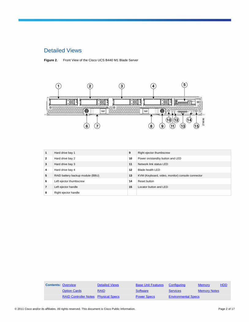
Figure 2. Front View of the Cisco UCS B440 M1 Blade Server
1 Hard drive bay 1 9 Right ejector thumbscrew
2 Hard drive bay 2 10 Power on/standby button and LED
3 Hard drive bay 3 11 Network link status LED
4 Hard drive bay 4 12 Blade health LED
5 RAID battery backup module (BBU) 13 KVM (Keyboard, video, monitor) console connector
6 Left ejector thumbscrew 14 Reset button
7 Left ejector handle 15 Locator button and LED
8 Right ejector handle
Contents: Overview Detailed Views Base Unit Features Configuring Memory HDD
Option Cards RAID Software Services Memory Notes
RAID Controller Notes Physical Specs Power Specs Environmental Specs

© 2011 Cisco and/or its affiliates. All rights reserved. This document is Cisco Public Information. Page 3 of 17
Figure 3. KVM Console Connector Cables
1 Connector to blade server slot 3 VGA Connection for a monitor
2 DB9 Serial connector 4 2-port USB connector for a mouse and keyboard
Contents: Overview Detailed Views Base Unit Features Configuring Memory HDD
Option Cards RAID Software Services Memory Notes
RAID Controller Notes Physical Specs Power Specs Environmental Specs
© 2011 Cisco and/or its affiliates. All rights reserved. This document is Cisco Public Information. Page 4 of 17
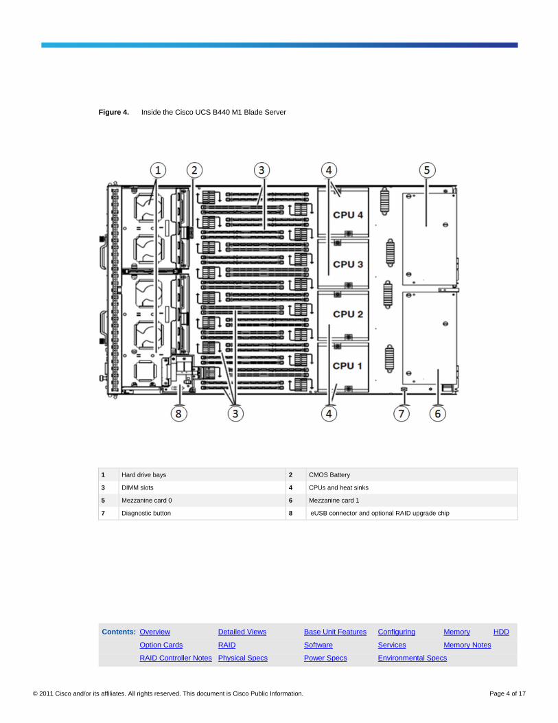
Figure 4. Inside the Cisco UCS B440 M1 Blade Server
1 Hard drive bays 2 CMOS Battery
3 DIMM slots 4 CPUs and heat sinks
5 Mezzanine card 0 6 Mezzanine card 1
7 Diagnostic button 8 eUSB connector and optional RAID upgrade chip
Contents: Overview Detailed Views Base Unit Features Configuring Memory HDD
Option Cards RAID Software Services Memory Notes
RAID Controller Notes Physical Specs Power Specs Environmental Specs

© 2011 Cisco and/or its affiliates. All rights reserved. This document is Cisco Public Information. Page 5 of 17
Base Unit Features
Table 1. Feature Specifications for the Cisco UCS B440 M1 Blade Server
Feature Specifications
CPU Up to four Intel® Xeon
® 7500 Series processors
Chipset Intel® 7500 chipset
Memory 32 DIMM slots (up to 512 GB)
Mezzanine slots Two dual-port mezzanine card slots for up to 40-Gbs I/O per blade
Internal storage devices Up to four front-accessible hot-swappable small form factor (SFF) hard drives with an LSI SAS2108 controller and integrated RAID.
Interfaces A console port is provided to give a direct connection to a blade server to allow operating system installation and other management tasks to be done directly rather than remotely. The port uses a local console cable dongle device included in the chassis accessory kit.
The local console connector cable (N20-BKVM) provides a connection into a Cisco UCS blade server, providing a DB9 serial connector, a VGA connector for a monitor, and dual USB ports for a keyboard and mouse.
Power subsystem Integrated in Cisco UCS 5108 chassis.
Fans Integrated in Cisco UCS 5108 chassis.
Integrated management processor Cisco Integrated Management Controller (CIMC) interface to the Cisco UCS Manager
Contents: Overview Detailed Views Base Unit Features Configuring Memory HDD
Option Cards RAID Software Services Memory Notes
RAID Controller Notes Physical Specs Power Specs Environmental Specs

© 2011 Cisco and/or its affiliates. All rights reserved. This document is Cisco Public Information. Page 6 of 17
Configuring the Cisco UCS B440 M1 Blade Server
UCS B440 M1 base server N20-B6740-2-UPG
STEP 1: Select the CPU type.
Select two or four CPUs from the following list. The CPUs must match (you cannot choose different CPUs for the
same server).
● 2.26 GHz Xeon X7560 130W 8C CPU/24MB cache A01-X0200
● 2.00 GHz Xeon X7550 130W 8C CPU/18MB cache A01-X0201
● 2.00 GHz Xeon E7540 105W 6C CPU/18MB cache A01-X0203
● 1.86 GHz Xeon E7520 95W 4C CPU/18MB cache A01-X0209
● 1.86 GHz Xeon L7555 95W 8C CPU/24MB cache A01-X0206
STEP 2: Select the memory type.
Please refer to the Memory Notes section for allowable memory configurations and rules/guidelines.
Select a minimum of one and a maximum of 16 DIMM kits from the following list:
● 8GB DDR3-1333MHz RDIMM/PC3-10600/2R/2x4GB Kit/Low Volt A02-M308GB3-2
● 16GB DDR3-1333MHz RDIMM/PC3-10600/2R/2x8GB Kit/Low Volt A02-M316GB3-2
● 32GB DDR3-1066MHz RDIMM/PC3-8500/4R/2x16GB Kit/Low Volt A02-M332GB3-2-L
● 8GB DDR3-1333MHz RDIMM/PC3-10600/2R/2x4GB Kit A02-M308GD5-2
● 16GB DDR3-1333MHz RDIMM/PC3-10600/2R/2x8GB Kit A02-M316GD5-2
Note: Memory must be populated in identical DIMM pairs.
Contents: Overview Detailed Views Base Unit Features Configuring Memory HDD
Option Cards RAID Software Services Memory Notes
RAID Controller Notes Physical Specs Power Specs Environmental Specs

© 2011 Cisco and/or its affiliates. All rights reserved. This document is Cisco Public Information. Page 7 of 17
STEP 3: Select the 2.5-inch small form factor (SFF) HDD type. (optional)
You can select a maximum of four drives:
● 73 GB 6Gb SAS 15K RPM SFF HDD/hot plug/drive sled mounted A03-D073GC2
● 146 GB 6Gb SAS 15K RPM SFF HDD/hot plug/drive sled mounted A03-D146GC2
● 300 GB 6Gb SAS 10K RPM SFF HDD/hot plug/drive sled mounted A03-D300GA2
● 600 GB 6Gb SAS 10K RPM SFF HDD/hot plug/drive sled mounted A03-D600GA2
STEP 4: Select from a list of mezzanine cards.
A mezzanine card is required. Select up to two cards and refer to the mix and match guidance below:
● UCS M81KR Virtual Interface Card/PCIe/2-port 10Gb N20-AC0002
(can be selected with N20-AQ0102, N20-AE0102, or N20-AQ002, N20-AE002))
● Cisco UCS M71KR-Q QLogic Converged Network Adapter N20-AQ0002
(can be selected with N20-AC0002)
● Cisco UCS M71KR-E Emulex Converged Network Adapter N20-AE0002
(can be selected with N20-AC0002)
● Cisco UCS NIC M51KR-B Broadcom BCM57711 Network Adapter N20-AB0002
(no mixing with other card options)
● Cisco UCS CNA M72KR-E Emulex Converged Network Adapter N20-AE0102
(can be selected with N20-AC0002)
● Cisco UCS CNA M72KR-Q QLogic Converged Network Adapter N20-AQ0102
(can be selected with N20-AC0002)
Contents: Overview Detailed Views Base Unit Features Configuring Memory HDD
Option Cards RAID Software Services Memory Notes
RAID Controller Notes Physical Specs Power Specs Environmental Specs

© 2011 Cisco and/or its affiliates. All rights reserved. This document is Cisco Public Information. Page 8 of 17
STEP 5: Select the RAID upgrade (optional).
The Cisco UCS B440 M1 Blade Server provides support for RAID 0, 1 with an option to upgrade to RAID 5, 6.
● RAID 5, 6 upgrade N20-BRAID-K1
● Write cache battery back up module N20-LBBU
STEP 6: Select the operating system (optional).
Various operating system options are available, as shown in the following list:
SUSE Linux Enterprise Server
● SLES/1yr subscription/svcs required/0 media SLES-1A
● SLES/3yr subscription/svcs required/0 media SLES-3A
Red Hat Enterprise Linux
● RHEL/2 Socket/1 Guest/1Yr Svcs Required RHEL-2S-1G-1A
● RHEL/2 Socket/1 Guest/3Yr Svcs Required RHEL-2S-1G-3A
● RHEL/2 Socket/4 Guest/1Yr Svcs Required RHEL-2S-4G-1A
● RHEL/2 Socket/4 Guest/3Yr Svcs Required RHEL-2S-4G-3A
● RHEL/2 Socket/U Guest/1Yr Svcs Required RHEL-2S-UG-1A
● RHEL/2 Socket/U Guest/3Yr Svcs Required RHEL-2S-UG-3A
● RHEL/4 Socket/1 Guest/1Yr Svcs Required RHEL-4S-1G-1A
● RHEL/4 Socket/1 Guest/3Yr Svcs Required RHEL-4S-1G-3A
● RHEL/4 Socket/4 Guest/1Yr Svcs Required RHEL-4S-4G-1A
● RHEL/4 Socket/4 Guest/3Yr Svcs Required RHEL-4S-4G-3A
● RHEL/4 Socket/U Guest/1Yr Svcs Required RHEL-4S-UG-1A
● RHEL/4 Socket/U Guest/3Yr Svcs Required RHEL-4S-UG-3A
Contents: Overview Detailed Views Base Unit Features Configuring Memory HDD
Option Cards RAID Software Services Memory Notes
RAID Controller Notes Physical Specs Power Specs Environmental Specs
© 2011 Cisco and/or its affiliates. All rights reserved. This document is Cisco Public Information. Page 9 of 17
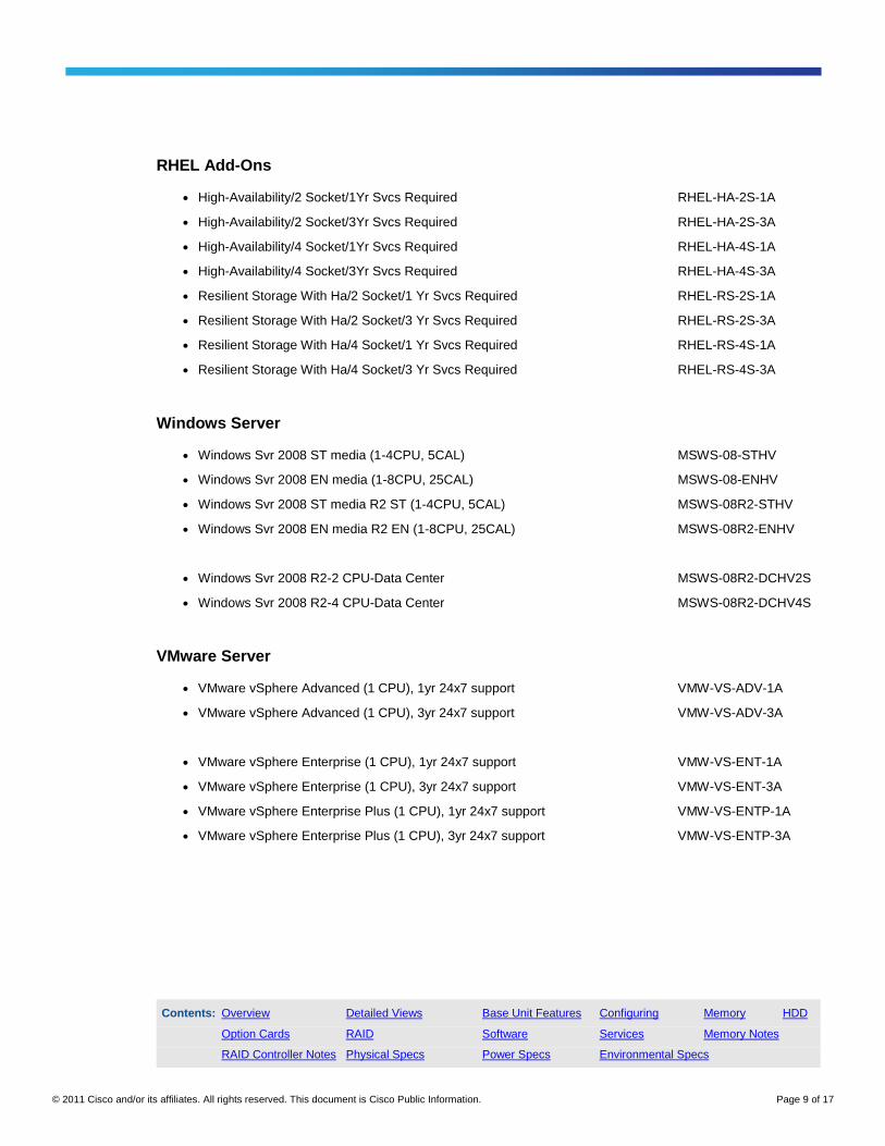
RHEL Add-Ons
● High-Availability/2 Socket/1Yr Svcs Required RHEL-HA-2S-1A
● High-Availability/2 Socket/3Yr Svcs Required RHEL-HA-2S-3A
● High-Availability/4 Socket/1Yr Svcs Required RHEL-HA-4S-1A
● High-Availability/4 Socket/3Yr Svcs Required RHEL-HA-4S-3A
● Resilient Storage With Ha/2 Socket/1 Yr Svcs Required RHEL-RS-2S-1A
● Resilient Storage With Ha/2 Socket/3 Yr Svcs Required RHEL-RS-2S-3A
● Resilient Storage With Ha/4 Socket/1 Yr Svcs Required RHEL-RS-4S-1A
● Resilient Storage With Ha/4 Socket/3 Yr Svcs Required RHEL-RS-4S-3A
Windows Server
● Windows Svr 2008 ST media (1-4CPU, 5CAL) MSWS-08-STHV
● Windows Svr 2008 EN media (1-8CPU, 25CAL) MSWS-08-ENHV
● Windows Svr 2008 ST media R2 ST (1-4CPU, 5CAL) MSWS-08R2-STHV
● Windows Svr 2008 EN media R2 EN (1-8CPU, 25CAL) MSWS-08R2-ENHV
● Windows Svr 2008 R2-2 CPU-Data Center MSWS-08R2-DCHV2S
● Windows Svr 2008 R2-4 CPU-Data Center MSWS-08R2-DCHV4S
VMware Server
● VMware vSphere Advanced (1 CPU), 1yr 24x7 support VMW-VS-ADV-1A
● VMware vSphere Advanced (1 CPU), 3yr 24x7 support VMW-VS-ADV-3A
● VMware vSphere Enterprise (1 CPU), 1yr 24x7 support VMW-VS-ENT-1A
● VMware vSphere Enterprise (1 CPU), 3yr 24x7 support VMW-VS-ENT-3A
● VMware vSphere Enterprise Plus (1 CPU), 1yr 24x7 support VMW-VS-ENTP-1A
● VMware vSphere Enterprise Plus (1 CPU), 3yr 24x7 support VMW-VS-ENTP-3A
Contents: Overview Detailed Views Base Unit Features Configuring Memory HDD
Option Cards RAID Software Services Memory Notes
RAID Controller Notes Physical Specs Power Specs Environmental Specs
© 2011 Cisco and/or its affiliates. All rights reserved. This document is Cisco Public Information. Page 10 of 17
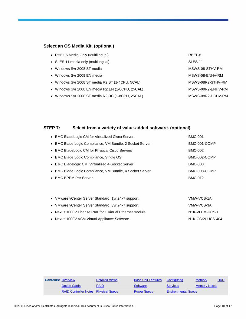
Select an OS Media Kit. (optional)
● RHEL 6 Media Only (Multilingual) RHEL-6
● SLES 11 media only (multilingual) SLES-11
● Windows Svr 2008 ST media MSWS-08-STHV-RM
● Windows Svr 2008 EN media MSWS-08-ENHV-RM
● Windows Svr 2008 ST media R2 ST (1-4CPU, 5CAL) MSWS-08R2-STHV-RM
● Windows Svr 2008 EN media R2 EN (1-8CPU, 25CAL) MSWS-08R2-ENHV-RM
● Windows Svr 2008 ST media R2 DC (1-8CPU, 25CAL) MSWS-08R2-DCHV-RM
STEP 7: Select from a variety of value-added software. (optional)
● BMC BladeLogic CM for Virtualized Cisco Servers BMC-001
● BMC Blade Logic Compliance, VM Bundle, 2 Socket Server BMC-001-COMP
● BMC BladeLogic CM for Physical Cisco Servers BMC-002
● BMC Blade Logic Compliance, Single OS BMC-002-COMP
● BMC Bladelogic CM, Virtualized 4-Socket Server BMC-003
● BMC Blade Logic Compliance, VM Bundle, 4 Socket Server BMC-003-COMP
● BMC BPPM Per Server BMC-012
● VMware vCenter Server Standard, 1yr 24x7 support VMW-VCS-1A
● VMware vCenter Server Standard, 3yr 24x7 support VMW-VCS-3A
● Nexus 1000V License PAK for 1 Virtual Ethernet module N1K-VLEM-UCS-1
● Nexus 1000V VSM Virtual Appliance Software N1K-CSK9-UCS-404
Contents: Overview Detailed Views Base Unit Features Configuring Memory HDD
Option Cards RAID Software Services Memory Notes
RAID Controller Notes Physical Specs Power Specs Environmental Specs

© 2011 Cisco and/or its affiliates. All rights reserved. This document is Cisco Public Information. Page 11 of 17
STEP 8: Select the appropriate services (optional).
You have a variety of service options, as listed here.
Cisco Unified Computing Mission Critical Support Service
This service delivers personalized technical account management, expedited technical support, and expert field
support engineering for the Cisco Unified Computing System™
The Mission Critical Support Service provides a designated technical account manager (TAM) who acts as a
strategic resource to help assure the unified computing environment runs at peak efficiency. Should a problem
arise that threatens business continuity, the TAM provides crisis management leadership, and customer IT staff
gets expedited access to Cisco’s award-winning Technical Assistance Center (TAC).
Please note: This service has qualification criteria. There should be US$1.2 million of Cisco Unified Computing
System equipment, 200 blades, and a single location to qualify for this service level:
● UC Mission Critical 24x7x4 On-site CON-UCM7-B67402U
● UC Mission Critical 24x7x2 On-site CON-UCM8-B67402U
Cisco Unified Computing Support Service
For support of the entire Unified Computing System, Cisco offers the Cisco Unified Computing Support Service.
This service provides expert software and hardware support to help sustain performance and high availability of the
unified computing environment. This service includes access to the award-winning Cisco Technical Assistance
Center (TAC) around the clock, from anywhere in the world.
For Cisco UCS blade servers, there is Smart Call Home, which provides proactive, embedded diagnostics and
real-time alerts. For systems that include the Cisco UCS Manager, the support service includes downloads of UCS
Manager upgrades. The Unified Computing Support Service includes flexible hardware replacement options,
including replacement in as little as two hours. There is also access to Cisco’s extensive online technical resources
to help maintain optimal efficiency and uptime of the unified computing environment.
Contents: Overview Detailed Views Base Unit Features Configuring Memory HDD
Option Cards RAID Software Services Memory Notes
RAID Controller Notes Physical Specs Power Specs Environmental Specs
© 2011 Cisco and/or its affiliates. All rights reserved. This document is Cisco Public Information. Page 12 of 17
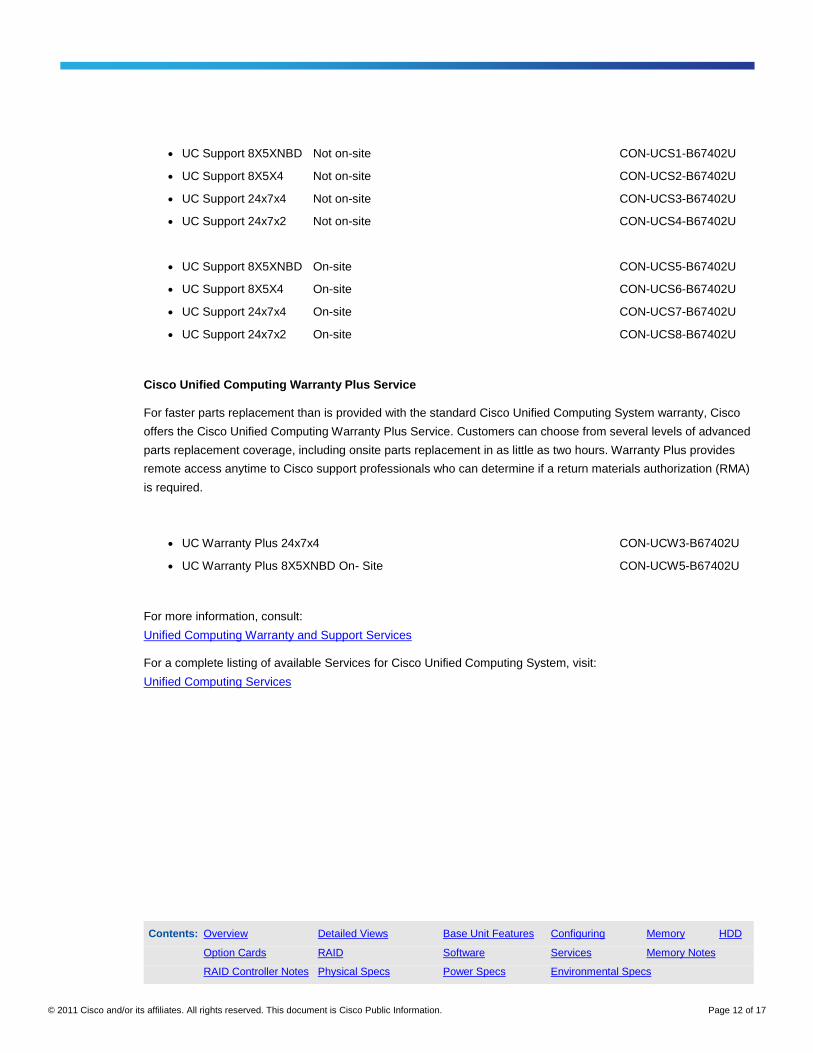
● UC Support 8X5XNBD Not on-site CON-UCS1-B67402U
● UC Support 8X5X4 Not on-site CON-UCS2-B67402U
● UC Support 24x7x4 Not on-site CON-UCS3-B67402U
● UC Support 24x7x2 Not on-site CON-UCS4-B67402U
● UC Support 8X5XNBD On-site CON-UCS5-B67402U
● UC Support 8X5X4 On-site CON-UCS6-B67402U
● UC Support 24x7x4 On-site CON-UCS7-B67402U
● UC Support 24x7x2 On-site CON-UCS8-B67402U
Cisco Unified Computing Warranty Plus Service
For faster parts replacement than is provided with the standard Cisco Unified Computing System warranty, Cisco
offers the Cisco Unified Computing Warranty Plus Service. Customers can choose from several levels of advanced
parts replacement coverage, including onsite parts replacement in as little as two hours. Warranty Plus provides
remote access anytime to Cisco support professionals who can determine if a return materials authorization (RMA)
is required.
● UC Warranty Plus 24x7x4 CON-UCW3-B67402U
● UC Warranty Plus 8X5XNBD On- Site CON-UCW5-B67402U
For more information, consult:
Unified Computing Warranty and Support Services
For a complete listing of available Services for Cisco Unified Computing System, visit:
Unified Computing Services
Contents: Overview Detailed Views Base Unit Features Configuring Memory HDD
Option Cards RAID Software Services Memory Notes
RAID Controller Notes Physical Specs Power Specs Environmental Specs

© 2011 Cisco and/or its affiliates. All rights reserved. This document is Cisco Public Information. Page 13 of 17
Product Notes
Memory Notes
The Cisco UCS B440 M1 High-Performance Blade Server contains 32 slots for installing DIMMs - eight for each
CPU. Each CPU has eight DIMM slots and DDR channels, with four pairs of DIMMs operating in lockstep.
Additional DIMMs must be installed in pairs, as laid out in Table 4.
The UCS B440 M1 blade server requires one matched pair of DIMMs attached to CPU 1 or CPU 2.
All four CPUs can boot and run from a single DIMM pair. DIMM pairs must be identical, but one DIMM pair on a
CPU can be different from other pairs.
DIMMs installed in slots for an absent CPU will not be recognized.
For optimal performance, distribute DIMMs evenly across all CPUs. As Figure 5 shows, DIMM connector latches
are color-coded blue, yellow, black, and white, and Cisco recommends installing memory in that order. It is also
recommended to install memory evenly across the installed CPUs.
The Cisco UCS B440 M1 server has four processor sockets, and each socket has access to 32 memory DIMM
slots. Table 3 shows current tested and qualified memory configurations.
Table 2. Memory Configuration for the Cisco UCS B440 M1 Blade Server
CPU 1 & 2 Total Mem (2 CPUs) CPU 3 & 4 Total Mem (4 CPUs)
2 x (8G Kit) 16 2 x (8G Kit) 32
4 x (8G Kit) 32 4 x (8G Kit) 64
2 x (16G kit) 32 2 x (16G kit) 64
6 x (8G kit) 48 6 x (8G kit) 96
8 x (8G Kit) 64 8 x (8G Kit) 128
4 x (16G kit) 64 4 x (16G kit) 128
2 x (32G Kit) 64 2 x (32G Kit) 128
6 x (16G Kit) 96 6 x (16G Kit) 192
8 x (16G kit) 128 8 x (16G kit) 256
4 x (32G kit) 128 4 x (32G kit) 256
8 x (32G kit) 256 8 x (32G kit) 512
Contents: Overview Detailed Views Base Unit Features Configuring Memory HDD
Option Cards RAID Software Services Memory Notes
RAID Controller Notes Physical Specs Power Specs Environmental Specs

© 2011 Cisco and/or its affiliates. All rights reserved. This document is Cisco Public Information. Page 14 of 17
Figure 5. DIMM Slot Numbering for the Cisco UCS B440 M1 Blade Server
Additional DIMMs must be installed in pairs, as laid out in Table 3. The slots inside the brackets are electrically
paired with each other, and should be populated with identical matched DIMMs that were ordered as a pair. Do not
swap a paired DIMM with a DIMM that is not identical in manufacturer part number.
Contents: Overview Detailed Views Base Unit Features Configuring Memory HDD
Option Cards RAID Software Services Memory Notes
RAID Controller Notes Physical Specs Power Specs Environmental Specs
© 2011 Cisco and/or its affiliates. All rights reserved. This document is Cisco Public Information. Page 15 of 17
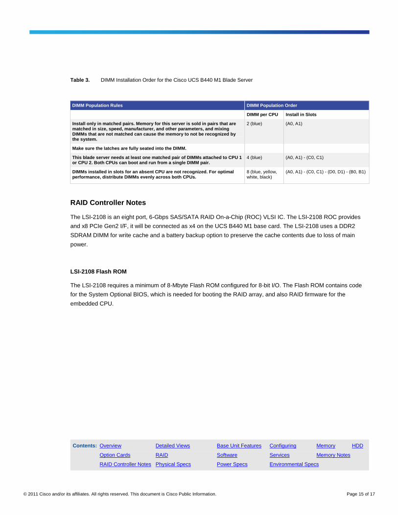
Table 3. DIMM Installation Order for the Cisco UCS B440 M1 Blade Server
DIMM Population Rules DIMM Population Order
DIMM per CPU Install in Slots
Install only in matched pairs. Memory for this server is sold in pairs that are matched in size, speed, manufacturer, and other parameters, and mixing DIMMs that are not matched can cause the memory to not be recognized by the system.
2 (blue) (A0, A1)
Make sure the latches are fully seated into the DIMM.
This blade server needs at least one matched pair of DIMMs attached to CPU 1 or CPU 2. Both CPUs can boot and run from a single DIMM pair.
4 (blue) (A0, A1) - (C0, C1)
DIMMs installed in slots for an absent CPU are not recognized. For optimal performance, distribute DIMMs evenly across both CPUs.
8 (blue, yellow, white, black)
(A0, A1) - (C0, C1) - (D0, D1) - (B0, B1)
RAID Controller Notes
The LSI-2108 is an eight port, 6-Gbps SAS/SATA RAID On-a-Chip (ROC) VLSI IC. The LSI-2108 ROC provides
and x8 PCIe Gen2 I/F, it will be connected as x4 on the UCS B440 M1 base card. The LSI-2108 uses a DDR2
SDRAM DIMM for write cache and a battery backup option to preserve the cache contents due to loss of main
power.
LSI-2108 Flash ROM
The LSI-2108 requires a minimum of 8-Mbyte Flash ROM configured for 8-bit I/O. The Flash ROM contains code
for the System Optional BIOS, which is needed for booting the RAID array, and also RAID firmware for the
embedded CPU.
Contents: Overview Detailed Views Base Unit Features Configuring Memory HDD
Option Cards RAID Software Services Memory Notes
RAID Controller Notes Physical Specs Power Specs Environmental Specs

© 2011 Cisco and/or its affiliates. All rights reserved. This document is Cisco Public Information. Page 16 of 17
Technical Specifications
Physical Dimensions Specifications
Table 4. Physical Dimension Specifications for the Cisco UCS B440 M1 Blade Server
Specification Value
Height 1.95 inches (50 mm)
Width 16.50 inches (419.1 mm)
Depth 24.4 inches (620 mm)
Weight 34.5 lbs (15.65 kg) *
*Note: The system weight listed here is an estimate for a fully configured system and will vary depending on number of peripheral devices.
Power Specifications
For configuration-specific power specifications, use the Cisco UCS Power Calculator at:
http://www.cisco.com/assets/cdc_content_elements/flash/dataCenter/cisco_ucs_power_calculator/
Contents: Overview Detailed Views Base Unit Features Configuring Memory HDD
Option Cards RAID Software Services Memory Notes
RAID Controller Notes Physical Specs Power Specs Environmental Specs

© 2011 Cisco and/or its affiliates. All rights reserved. This document is Cisco Public Information. Page 17 of 17
Environmental Specifications
Table 5. Environmental Specifications for Cisco UCS B440 M1 Blade Server
Environment Specification
Temperature operating 50 to 95°F (10 to 35°C)
Temperature nonoperating -40 to 149°F (-40 to 65°C)
Altitude operating 0 to 10,000 ft (0 to 3000m); maximum ambient temperature decreases by 1°C per 300m
Altitude nonoperating 40,000 ft (12,000m)
Humidity 5 to 93% noncondensing
Safety ● UL 60950-1
● CAN/CSA-C22.2 No. 60950-1
● EN 60950-1
● IEC 60950-1
● AS/NZS 60950-1
● GB4943
EMC: Emissions ● 47CFR Part 15 (CFR 47) Class A
● AS/NZS CISPR22 Class A
● CISPR2 2 Class A
● EN55022 Class A
● ICES003 Class A
● VCCI Class A
● EN61000-3-2
● EN61000-3-3
● KN22 Class A
● CNS13438 Class A
EMC: Immunity ● EN50082-1
● EN61000-6-1
● EN55024
● CISPR24
● EN300386
● KN 61000-4 Series
For More Information
Please visit http://www.cisco.com/go/ucs.
Printed in USA C17-662217-03 09/11