Cisco SIP IP Phone Administrator Guide - VoIP Info · The Cisco SIP IP Phone Administrator ... and...
192
Corporate Headquarters Cisco Systems, Inc. 170 West Tasman Drive San Jose, CA 95134-1706 USA http://www.cisco.com Tel: 408 526-4000 800 553-NETS (6387) Fax: 408 526-4100 Cisco SIP IP Phone Administrator Guide Release 4.2 January 2003
Transcript of Cisco SIP IP Phone Administrator Guide - VoIP Info · The Cisco SIP IP Phone Administrator ... and...
Cisco SIP IP Phone Administrator GuideRelease 4.2January 2003
Corporate HeadquartersCisco Systems, Inc.170 West Tasman DriveSan Jose, CA 95134-1706 USAhttp://www.cisco.comTel: 408 526-4000
800 553-NETS (6387)Fax: 408 526-4100

THE SPECIFICATIONS AND INFORMATION REGARDING THE PRODUCTS IN THIS MANUAL ARE SUBJECT TO CHANGE WITHOUT NOTICE. ALL STATEMENTS, INFORMATION, AND RECOMMENDATIONS IN THIS MANUAL ARE BELIEVED TO BE ACCURATE BUT ARE PRESENTED WITHOUT WARRANTY OF ANY KIND, EXPRESS OR IMPLIED. USERS MUST TAKE FULL RESPONSIBILITY FOR THEIR APPLICATION OF ANY PRODUCTS.
THE SOFTWARE LICENSE AND LIMITED WARRANTY FOR THE ACCOMPANYING PRODUCT ARE SET FORTH IN THE INFORMATION PACKET THAT SHIPPED WITH THE PRODUCT AND ARE INCORPORATED HEREIN BY THIS REFERENCE. IF YOU ARE UNABLE TO LOCATE THE SOFTWARE LICENSE OR LIMITED WARRANTY, CONTACT YOUR CISCO REPRESENTATIVE FOR A COPY.
NOTWITHSTANDING ANY OTHER WARRANTY HEREIN, ALL DOCUMENT FILES AND SOFTWARE OF THESE SUPPLIERS ARE PROVIDED “AS IS” WITH ALL FAULTS. CISCO AND THE ABOVE-NAMED SUPPLIERS DISCLAIM ALL WARRANTIES, EXPRESSED OR IMPLIED, INCLUDING, WITHOUT LIMITATION, THOSE OF MERCHANTABILITY, FITNESS FOR A PARTICULAR PURPOSE AND NONINFRINGEMENT OR ARISING FROM A COURSE OF DEALING, USAGE, OR TRADE PRACTICE.
IN NO EVENT SHALL CISCO OR ITS SUPPLIERS BE LIABLE FOR ANY INDIRECT, SPECIAL, CONSEQUENTIAL, OR INCIDENTAL DAMAGES, INCLUDING, WITHOUT LIMITATION, LOST PROFITS OR LOSS OR DAMAGE TO DATA ARISING OUT OF THE USE OR INABILITY TO USE THIS MANUAL, EVEN IF CISCO OR ITS SUPPLIERS HAVE BEEN ADVISED OF THE POSSIBILITY OF SUCH DAMAGES.
CCIP, the Cisco Arrow logo, the Cisco Powered Network mark, the Cisco Systems Verified logo, Cisco Unity, Follow Me Browsing, FormShare, iQ Breakthrough, iQ Expertise, iQ FastTrack, the iQ Logo, iQ Net Readiness Scorecard, Networking Academy, ScriptShare, SMARTnet, TransPath, and Voice LAN are trademarks of Cisco Systems, Inc.; Changing the Way We Work, Live, Play, and Learn, Discover All That’s Possible, The Fastest Way to Increase Your Internet Quotient, and iQuick Study are service marks of Cisco Systems, Inc.; and Aironet, ASIST, BPX, Catalyst, CCDA, CCDP, CCIE, CCNA, CCNP, Cisco, the Cisco Certified Internetwork Expert logo, Cisco IOS, the Cisco IOS logo, Cisco Press, Cisco Systems, Cisco Systems Capital, the Cisco Systems logo, Empowering the Internet Generation, Enterprise/Solver, EtherChannel, EtherSwitch, Fast Step, GigaStack, Internet Quotient, IOS, IP/TV, LightStream, MGX, MICA, the Networkers logo, Network Registrar, Packet, PIX, Post-Routing, Pre-Routing, RateMUX, Registrar, SlideCast, StrataView Plus, Stratm, SwitchProbe, TeleRouter, and VCO are registered trademarks of Cisco Systems, Inc. and/or its affiliates in the U.S. and certain other countries.
All other trademarks mentioned in this document or website are the property of their respective owners. The use of the word partner does not imply a partnership relationship between Cisco and any other company. (0208R)
Cisco SIP IP Phone Administrator GuideCopyright © 2003, Cisco Systems, Inc.All rights reserved.
C O N T E N T S
Preface vii
Overview vii
Who Should Use This Guide vii
Objectives viii
Document Organization viii
Document Conventions viii
Related Documentation x
Obtaining Documentation xi
Cisco.com xi
Documentation CD-ROM xi
Ordering Documentation xi
Documentation Feedback xii
Obtaining Technical Assistance xii
Cisco.com xii
Technical Assistance Center xii
Obtaining Additional Publications and Information xiii
C H A P T E R 1 Product Overview 1-1
What Is Session Initiation Protocol? 1-1
Components of SIP 1-2
What Is the Cisco SIP IP Phone? 1-3
BTXML Support 1-5
Cisco CallManager XML Support 1-5
Supported Features 1-6
Supported Protocols 1-11
Prerequisites 1-12
Cisco SIP IP Phone Connections 1-12
Connecting to the Network 1-13
Connecting to Power 1-13
Using a Headset 1-14
The Cisco SIP IP Phone with a Catalyst Switch 1-14
iiiCisco SIP IP Phone Administrator Guide
Contents
C H A P T E R 2 Getting Started with Your Cisco SIP IP Phone 2-1
Overview of the Initialization Process 2-1
Installing the Cisco SIP IP Phone 2-2
Installation Task Summary 2-2
Downloading Files to Your TFTP Server 2-3
Configuring SIP Parameters 2-4
Configuring Network Parameters 2-9
Connecting the Phone 2-11
Verifying Startup 2-14
Using the Cisco SIP IP Phone Menu Interface 2-15
Reading the Cisco SIP IP Phone Icons 2-15
Customizing the Cisco SIP IP Phone Ring Types 2-17
Creating Dial Plans 2-17
C H A P T E R 3 Managing Cisco SIP IP Phones 3-1
Changing Your Configuration 3-1
Modifying the Network Settings 3-2
Entering Configuration Mode 3-2
Unlocking Configuration Mode 3-2
Locking Configuration Mode 3-3
Changing the Network Settings 3-3
Modifying the SIP Settings 3-6
Modifying SIP Parameters via a TFTP Server 3-9
Modifying the SIP Parameters Directly on Your Phone 3-26
Using the Command-Line Interface 3-29
Setting the Date, Time, and Daylight Saving Time 3-35
Erasing the Locally Defined Settings 3-41
Erasing the Locally Defined Network Settings 3-41
Erasing the Locally Defined SIP Settings 3-41
Accessing Status Information 3-42
Viewing Status Messages 3-42
Viewing Network Statistics 3-43
Viewing the Firmware Version 3-44
Upgrading the Cisco SIP IP Phone Firmware 3-44
Upgrading from Release 2.2 or Later to Current Release 3-45
Upgrading from Release 2.1 or Earlier to Current Release 3-45
Dual Booting from SCCP or MGCP to a SIP Release 3-46
ivCisco SIP IP Phone Administrator Guide
Contents
Performing an Image Upgrade and Remote Reboot 3-46
A P P E N D I X A Information About SIP Compliance with RFC 3261 A-1
SIP Functions A-1
SIP Methods A-2
SIP Responses A-2
1xx Response—Information Responses A-2
2xx Response—Successful Responses A-3
3xx Response—Redirection Responses A-3
4xx Response—Request Failure Responses A-4
5xx Response—Server Failure Responses A-6
6xx Response—Global Responses A-7
SIP Header Fields A-7
SIP Session Description Protocol Usage A-8
Transport Layer Protocols A-9
SIP Security Authentication A-9
SIP DNS Records Usage A-9
SIP DTMF Digit Transport A-9
A P P E N D I X B SIP Call Flows B-1
Call Flow Scenarios for Successful Calls B-1
Gateway to Cisco SIP IP Phone B-2
Cisco SIP IP Phone to Cisco SIP IP Phone B-7
Call Flow Scenarios for Failed Calls B-52
Gateway to Cisco SIP IP Phone B-52
Cisco SIP IP Phone to Cisco SIP IP Phone B-57
A P P E N D I X C Technical Specifications C-1
Physical and Operating Environment Specifications C-1
Cable Specifications C-2
Regulatory Safety Compliance C-2
Connections Specifications C-3
A P P E N D I X D Translated Safety Warnings D-1
Installation Warning D-1
Product Disposal Warning D-1
Lightning Activity Warning D-2
vCisco SIP IP Phone Administrator Guide

Contents
SELV Circuit Warning D-2
Circuit Breaker (15A) Warning D-3
GL O S S A R Y
IN D E X
viCisco SIP IP Phone Administrator Guide
Preface
This document describes the Cisco SIP IP phone. This preface describes the objectives and organization of the document and explains how to find additional information on related products and services. It contains the following sections:
• Overview, page vii
• Who Should Use This Guide, page vii
• Objectives, page viii
• Document Organization, page viii
• Document Conventions, page viii
• Related Documentation, page x
• Obtaining Technical Assistance, page xii
OverviewThe Cisco SIP IP Phone Administrator Guide provides information about how to set up, connect cables to, and configure a Cisco Session Initiation Protocol (SIP) IP Phone 7940 or 7960 (hereafter referred to as a Cisco SIP IP phone). It also provides information on how to configure the network and SIP settings and change the settings and options of the Cisco SIP IP phone. The administrator guide also includes reference information such as Cisco SIP IP phone call flows and compliance information.
Who Should Use This GuideNetwork engineers, system administrators, or telecommunications engineers should use this guide to learn the tasks required to set up the Cisco SIP IP phone in the network. The described tasks are administration-level tasks and are not intended for the end users of the phones. Many of the tasks involve configuring network settings that could affect the ability of the phone to function in the network and require an understanding of IP networking and telephony concepts.
viiCisco SIP IP Phone Administrator Guide
PrefaceObjectives
ObjectivesThe Cisco SIP IP Phone Administrator Guide provides necessary information to get the Cisco SIP IP phone operational in a Voice-over-IP (VoIP) network. It is not the intent of this administrator guide to provide information on how to implement a SIP VoIP network. For information on implementing a SIP VoIP network, refer to the documents listed in the “Related Documentation” section on page x.
Document OrganizationThis document is organized into the following chapters:
• Chapter 1, “Product Overview”—Describes SIP and the Cisco SIP IP phone.
• Chapter 2, “Getting Started with Your Cisco SIP IP Phone”—Describes how to install, connect, and configure the Cisco SIP IP phone.
• Chapter 3, “Managing Cisco SIP IP Phones”—Describes how to modify the Cisco SIP IP phone network and settings, how to access network and call status information, and how to upgrade the firmware.
• Appendix A, “Information About SIP Compliance with RFC 3261”—Provides reference information about the Cisco SIP IP phone compliance to RFC 3261.
• Appendix B, “SIP Call Flows”—Provides reference information about the Cisco SIP IP phone call flows.
• Appendix C, “Technical Specifications”—Lists the physical and operating environment specifications, cable specifications, and connection specifications.
• Appendix D, “Translated Safety Warnings”—Lists translated safety warnings that should be followed when installing an electrical device such as the Cisco SIP IP phone.
Document ConventionsThis document uses the following conventions:
• Commands and keywords are in boldface font.
• Arguments for which you supply values are in italic font.
• Elements in square brackets ([ ]) are optional.
• Required alternative keywords are grouped in braces and separated by vertical bars (for example, {x | y | z}).
• Optional alternative keywords are grouped in brackets and separated by vertical bars (for example, [x | y | z]).
• Terminal sessions and information that the system displays are in screen font.
• Information that you must enter is in boldface screen font.
Note Means reader take note. Notes contain helpful suggestions or references to material not covered in the publication.
viiiCisco SIP IP Phone Administrator Guide
PrefaceDocument Conventions
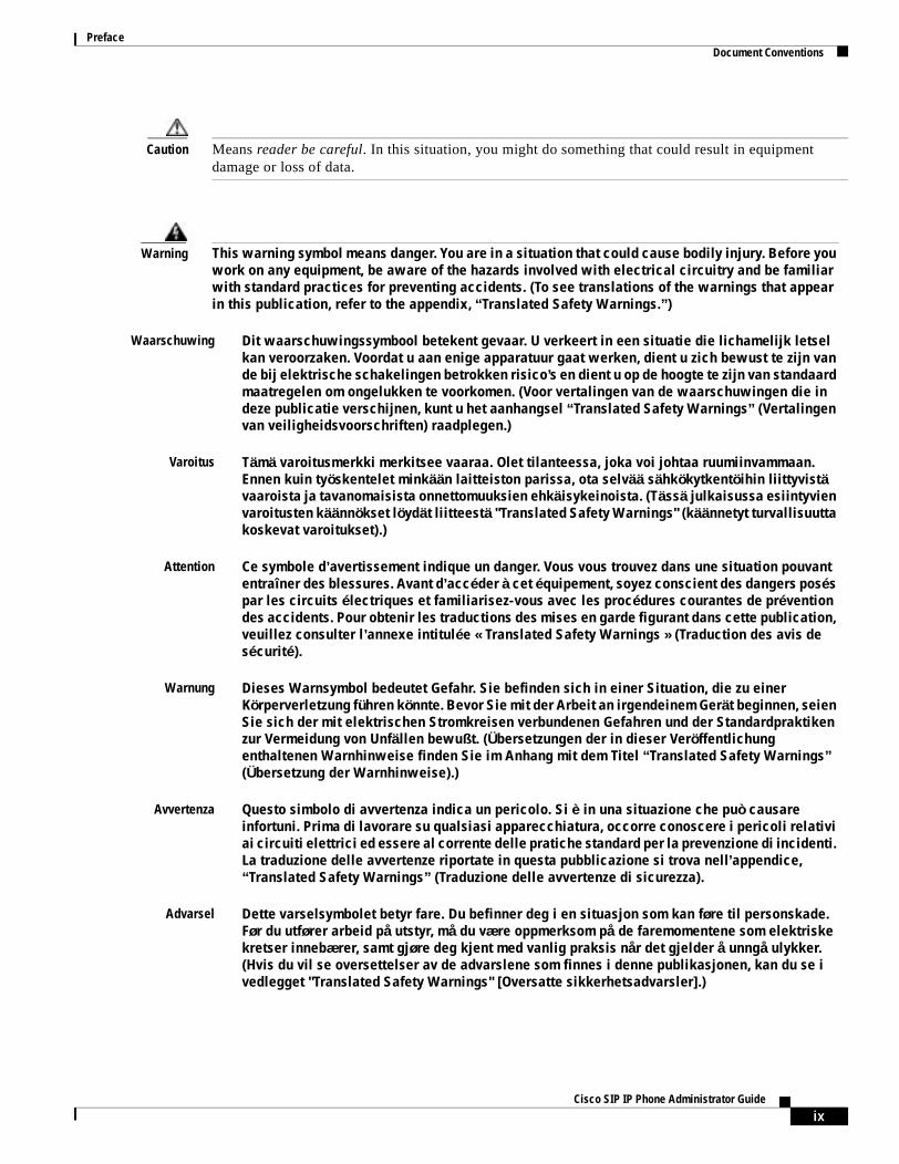
Caution Means reader be careful. In this situation, you might do something that could result in equipment damage or loss of data.
Warning This warning symbol means danger. You are in a situation that could cause bodily injury. Before you work on any equipment, be aware of the hazards involved with electrical circuitry and be familiar with standard practices for preventing accidents. (To see translations of the warnings that appear in this publication, refer to the appendix, “Translated Safety Warnings.”)
Waarschuwing Dit waarschuwingssymbool betekent gevaar. U verkeert in een situatie die lichamelijk letsel kan veroorzaken. Voordat u aan enige apparatuur gaat werken, dient u zich bewust te zijn van de bij elektrische schakelingen betrokken risico’s en dient u op de hoogte te zijn van standaard maatregelen om ongelukken te voorkomen. (Voor vertalingen van de waarschuwingen die in deze publicatie verschijnen, kunt u het aanhangsel “Translated Safety Warnings” (Vertalingen van veiligheidsvoorschriften) raadplegen.)
Varoitus Tämä varoitusmerkki merkitsee vaaraa. Olet tilanteessa, joka voi johtaa ruumiinvammaan. Ennen kuin työskentelet minkään laitteiston parissa, ota selvää sähkökytkentöihin liittyvistä vaaroista ja tavanomaisista onnettomuuksien ehkäisykeinoista. (Tässä julkaisussa esiintyvien varoitusten käännökset löydät liitteestä "Translated Safety Warnings" (käännetyt turvallisuutta koskevat varoitukset).)
Attention Ce symbole d’avertissement indique un danger. Vous vous trouvez dans une situation pouvant entraîner des blessures. Avant d’accéder à cet équipement, soyez conscient des dangers posés par les circuits électriques et familiarisez-vous avec les procédures courantes de prévention des accidents. Pour obtenir les traductions des mises en garde figurant dans cette publication, veuillez consulter l’annexe intitulée « Translated Safety Warnings » (Traduction des avis de sécurité).
Warnung Dieses Warnsymbol bedeutet Gefahr. Sie befinden sich in einer Situation, die zu einer Körperverletzung führen könnte. Bevor Sie mit der Arbeit an irgendeinem Gerät beginnen, seien Sie sich der mit elektrischen Stromkreisen verbundenen Gefahren und der Standardpraktiken zur Vermeidung von Unfällen bewußt. (Übersetzungen der in dieser Veröffentlichung enthaltenen Warnhinweise finden Sie im Anhang mit dem Titel “Translated Safety Warnings” (Übersetzung der Warnhinweise).)
Avvertenza Questo simbolo di avvertenza indica un pericolo. Si è in una situazione che può causare infortuni. Prima di lavorare su qualsiasi apparecchiatura, occorre conoscere i pericoli relativi ai circuiti elettrici ed essere al corrente delle pratiche standard per la prevenzione di incidenti. La traduzione delle avvertenze riportate in questa pubblicazione si trova nell’appendice, “Translated Safety Warnings” (Traduzione delle avvertenze di sicurezza).
Advarsel Dette varselsymbolet betyr fare. Du befinner deg i en situasjon som kan føre til personskade. Før du utfører arbeid på utstyr, må du være oppmerksom på de faremomentene som elektriske kretser innebærer, samt gjøre deg kjent med vanlig praksis når det gjelder å unngå ulykker. (Hvis du vil se oversettelser av de advarslene som finnes i denne publikasjonen, kan du se i vedlegget "Translated Safety Warnings" [Oversatte sikkerhetsadvarsler].)
ixCisco SIP IP Phone Administrator Guide
PrefaceRelated Documentation
Related DocumentationThe following is a list of related Cisco SIP VoIP publications. For more information about implementing a SIP VoIP network, refer to the following publications:
• Session Initiation Protocol Gateway Call Flows
• Cisco IP Phone 7960 and 7940 Series at a Glance
• Regulatory Compliance and Safety Information for the Cisco IP Phone 7960, 7940, and 7910 Series
• Installing the Wall Mount Kit for the Cisco IP Phone
The following is a list of Cisco VoIP publications that provide information about implementing a VoIP network:
• Cisco IOS Voice, Video, and Fax Configuration Guide, Release 12.2
• Cisco IOS Voice, Video, and Fax Command Reference, Release 12.2 T
• Cisco IOS IP Configuration Guide, Release 12.2
• Cisco IOS IP Command Reference, Volume 1 of 3: Addressing and Services, Release 12.2 T
• Cisco IOS IP Command Reference, Volume 2 of 3: Routing Protocols, Release 12.2 T
• Cisco IOS IP Command Reference, Volume 3 of 3: Multicast, Release 12.2 T
Aviso Este símbolo de aviso indica perigo. Encontra-se numa situação que lhe poderá causar danos fisicos. Antes de começar a trabalhar com qualquer equipamento, familiarize-se com os perigos relacionados com circuitos eléctricos, e com quaisquer práticas comuns que possam prevenir possíveis acidentes. (Para ver as traduções dos avisos que constam desta publicação, consulte o apêndice “Translated Safety Warnings” - “Traduções dos Avisos de Segurança”).
Advertencia Este símbolo de aviso significa peligro. Existe riesgo para su integridad física. Antes de manipular cualquier equipo, considerar los riesgos que entraña la corriente eléctrica y familiarizarse con los procedimientos estándar de prevención de accidentes. (Para ver traducciones de las advertencias que aparecen en esta publicación, consultar el apéndice titulado “Translated Safety Warnings.”)
Varning! Denna varningssymbol signalerar fara. Du befinner dig i en situation som kan leda till personskada. Innan du utför arbete på någon utrustning måste du vara medveten om farorna med elkretsar och känna till vanligt förfarande för att förebygga skador. (Se förklaringar av de varningar som förekommer i denna publikation i appendix "Translated Safety Warnings" [Översatta säkerhetsvarningar].)
xCisco SIP IP Phone Administrator Guide
PrefaceObtaining Documentation
Obtaining DocumentationCisco provides several ways to obtain documentation, technical assistance, and other technical resources. These sections explain how to obtain technical information from Cisco Systems.
Cisco.comYou can access the most current Cisco documentation on the World Wide Web at this URL:
http://www.cisco.com/univercd/home/home.htm
You can access the Cisco website at this URL:
http://www.cisco.com
International Cisco web sites can be accessed from this URL:
http://www.cisco.com/public/countries_languages.shtml
Documentation CD-ROMCisco documentation and additional literature are available in a Cisco Documentation CD-ROM package, which may have shipped with your product. The Documentation CD-ROM is updated monthly and may be more current than printed documentation. The CD-ROM package is available as a single unit or through an annual subscription.
Registered Cisco.com users can order the Documentation CD-ROM (product number DOC-CONDOCCD=) through the online Subscription Store:
http://www.cisco.com/go/subscription
Ordering DocumentationYou can find instructions for ordering documentation at this URL:
http://www.cisco.com/univercd/cc/td/doc/es_inpck/pdi.htm
You can order Cisco documentation in these ways:
• Registered Cisco.com users (Cisco direct customers) can order Cisco product documentation from the Networking Products MarketPlace:
http://www.cisco.com/en/US/partner/ordering/index.shtml
• Registered Cisco.com users can order the Documentation CD-ROM (Customer Order Number DOC-CONDOCCD=) through the online Subscription Store:
http://www.cisco.com/go/subscription
• Nonregistered Cisco.com users can order documentation through a local account representative by calling Cisco Systems Corporate Headquarters (California, U.S.A.) at 408 526-7208 or, elsewhere in North America, by calling 800 553-NETS (6387).
xiCisco SIP IP Phone Administrator Guide
PrefaceObtaining Technical Assistance
Documentation FeedbackYou can submit comments electronically on Cisco.com. On the Cisco Documentation home page, click Feedback at the top of the page.
You can e-mail your comments to [email protected].
You can submit your comments by mail by using the response card behind the front cover of your document or by writing to the following address:
Cisco SystemsAttn: Customer Document Ordering170 West Tasman DriveSan Jose, CA 95134-9883
We appreciate your comments.
Obtaining Technical AssistanceCisco provides Cisco.com, which includes the Cisco Technical Assistance Center (TAC) Website, as a starting point for all technical assistance. Customers and partners can obtain online documentation, troubleshooting tips, and sample configurations from the Cisco TAC website. Cisco.com registered users have complete access to the technical support resources on the Cisco TAC website, including TAC tools and utilities.
Cisco.comCisco.com offers a suite of interactive, networked services that let you access Cisco information, networking solutions, services, programs, and resources at any time, from anywhere in the world.
Cisco.com provides a broad range of features and services to help you with these tasks:
• Streamline business processes and improve productivity
• Resolve technical issues with online support
• Download and test software packages
• Order Cisco learning materials and merchandise
• Register for online skill assessment, training, and certification programs
To obtain customized information and service, you can self-register on Cisco.com at this URL:
http://www.cisco.com
Technical Assistance CenterThe Cisco TAC is available to all customers who need technical assistance with a Cisco product, technology, or solution. Two levels of support are available: the Cisco TAC website and the Cisco TAC Escalation Center. The avenue of support that you choose depends on the priority of the problem and the conditions stated in service contracts, when applicable.
We categorize Cisco TAC inquiries according to urgency:
• Priority level 4 (P4)—You need information or assistance concerning Cisco product capabilities, product installation, or basic product configuration.
xiiCisco SIP IP Phone Administrator Guide
PrefaceObtaining Additional Publications and Information
• Priority level 3 (P3)—Your network performance is degraded. Network functionality is noticeably impaired, but most business operations continue.
• Priority level 2 (P2)—Your production network is severely degraded, affecting significant aspects of business operations. No workaround is available.
• Priority level 1 (P1)—Your production network is down, and a critical impact to business operations will occur if service is not restored quickly. No workaround is available.
Cisco TAC Website
You can use the Cisco TAC website to resolve P3 and P4 issues yourself, saving both cost and time. The site provides around-the-clock access to online tools, knowledge bases, and software. To access the Cisco TAC website, go to this URL:
http://www.cisco.com/tac
All customers, partners, and resellers who have a valid Cisco service contract have complete access to the technical support resources on the Cisco TAC website. Some services on the Cisco TAC website require a Cisco.com login ID and password. If you have a valid service contract but do not have a login ID or password, go to this URL to register:
http://tools.cisco.com/RPF/register/register.do
If you are a Cisco.com registered user, and you cannot resolve your technical issues by using the Cisco TAC website, you can open a case online at this URL:
http://www.cisco.com/en/US/support/index.html
If you have Internet access, we recommend that you open P3 and P4 cases through the Cisco TAC website so that you can describe the situation in your own words and attach any necessary files.
Cisco TAC Escalation Center
The Cisco TAC Escalation Center addresses priority level 1 or priority level 2 issues. These classifications are assigned when severe network degradation significantly impacts business operations. When you contact the TAC Escalation Center with a P1 or P2 problem, a Cisco TAC engineer automatically opens a case.
To obtain a directory of toll-free Cisco TAC telephone numbers for your country, go to this URL:
http://www.cisco.com/warp/public/687/Directory/DirTAC.shtml
Before calling, please check with your network operations center to determine the level of Cisco support services to which your company is entitled: for example, SMARTnet, SMARTnet Onsite, or Network Supported Accounts (NSA). When you call the center, please have available your service agreement number and your product serial number.
Obtaining Additional Publications and InformationInformation about Cisco products, technologies, and network solutions is available from various online and printed sources.
• The Cisco Product Catalog describes the networking products offered by Cisco Systems as well as ordering and customer support services. Access the Cisco Product Catalog at this URL:
http://www.cisco.com/en/US/products/products_catalog_links_launch.html
xiiiCisco SIP IP Phone Administrator Guide
PrefaceObtaining Additional Publications and Information
• Cisco Press publishes a wide range of networking publications. Cisco suggests these titles for new and experienced users: Internetworking Terms and Acronyms Dictionary, Internetworking Technology Handbook, Internetworking Troubleshooting Guide, and the Internetworking Design Guide. For current Cisco Press titles and other information, go to Cisco Press online at this URL:
http://www.ciscopress.com
• Packet magazine is the Cisco monthly periodical that provides industry professionals with the latest information about the field of networking. You can access Packet magazine at this URL:
http://www.cisco.com/en/US/about/ac123/ac114/about_cisco_packet_magazine.html
• iQ Magazine is the Cisco monthly periodical that provides business leaders and decision makers with the latest information about the networking industry. You can access iQ Magazine at this URL:
http://business.cisco.com/prod/tree.taf%3fasset_id=44699&public_view=true&kbns=1.html
• Internet Protocol Journal is a quarterly journal published by Cisco Systems for engineering professionals involved in the design, development, and operation of public and private internets and intranets. You can access the Internet Protocol Journal at this URL:
http://www.cisco.com/en/US/about/ac123/ac147/about_cisco_the_internet_protocol_journal.html
• Training—Cisco offers world-class networking training, with current offerings in network training listed at this URL:
http://www.cisco.com/en/US/learning/le31/learning_recommended_training_list.html
xivCisco SIP IP Phone Administrator Guide
C H A P T E R 1
Product OverviewThis chapter contains the following information about the Cisco SIP IP phone:
• What Is Session Initiation Protocol?, page 1-1
• What Is the Cisco SIP IP Phone?, page 1-3
• Prerequisites, page 1-12
• Cisco SIP IP Phone Connections, page 1-12
• The Cisco SIP IP Phone with a Catalyst Switch, page 1-14
What Is Session Initiation Protocol?Session Initiation Protocol (SIP) is the Internet Engineering Task Force (IETF) standard for multimedia conferencing over IP. SIP is an ASCII-based, application-layer control protocol (defined in RFC 3261) that can be used to establish, maintain, and terminate calls between two or more endpoints.
Like other VoIP protocols, SIP is designed to address the functions of signaling and session management within a packet telephony network. Signaling allows call information to be carried across network boundaries. Session management provides the ability to control the attributes of an end-to-end call.
SIP provides the capabilities to do the following:
• Determine the location of the target endpoint—SIP supports address resolution, name mapping, and call redirection.
• Determine the media capabilities of the target endpoint—Via Session Description Protocol (SDP), SIP determines the “lowest level” of common services between the endpoints. Conferences are established using only the media capabilities that can be supported by all endpoints.
• Determine the availability of the target endpoint—If a call cannot be completed because the target endpoint is unavailable, SIP determines whether the called party is already on the phone or did not answer in the allotted number of rings. It then returns a message that indicates why the target endpoint was unavailable.
• Establish a session between the originating and target endpoint—If the call can be completed, SIP establishes a session between the endpoints. SIP also supports midcall changes, such as the addition of another endpoint to the conference or the changing of a media characteristic or codec.
• Handle the transfer and termination of calls—SIP supports the transfer of calls from one endpoint to another. During a call transfer, SIP simply establishes a session between the transferee and a new endpoint (specified by the transferring party) and terminates the session between the transferee and the transferring party. At the end of a call, SIP terminates the sessions between all parties.
1-1Cisco SIP IP Phone Administrator Guide
Chapter 1 Product OverviewWhat Is Session Initiation Protocol?
Conferences can consist of two or more users and can be established using multicast or multiple unicast sessions.
Note The term conference means an established session (or call) between two or more endpoints. In this document, the terms conference and call are used interchangeably.
Components of SIPSIP is a peer-to-peer protocol. The peers in a session are called user agents (UAs). A user agent can function in one of the following roles:
• User agent client (UAC)—A client application that initiates the SIP request.
• User agent server (UAS)—A server application that contacts the user when a SIP request is received and that returns a response on behalf of the user.
Typically, a SIP endpoint is capable of functioning as both a UAC and a UAS, but functions only as one or the other per transaction. Whether the endpoint functions as a UAC or a UAS depends on the UA that initiated the request.
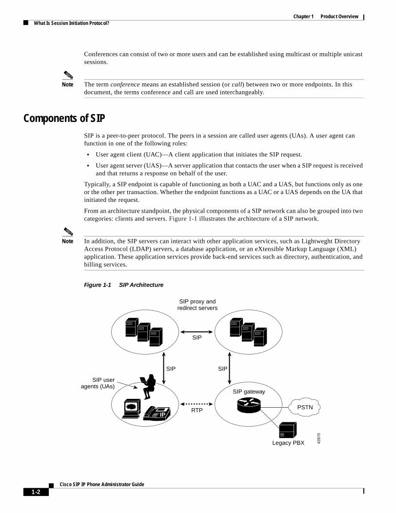
From an architecture standpoint, the physical components of a SIP network can also be grouped into two categories: clients and servers. Figure 1-1 illustrates the architecture of a SIP network.
Note In addition, the SIP servers can interact with other application services, such as Lightweght Directory Access Protocol (LDAP) servers, a database application, or an eXtensible Markup Language (XML) application. These application services provide back-end services such as directory, authentication, and billing services.
Figure 1-1 SIP Architecture
IP
SIP useragents (UAs)
RTP
SIP
SIP proxy andredirect servers
SIP gateway
PSTN
Legacy PBX
SIP SIP
4287
0
1-2Cisco SIP IP Phone Administrator Guide

Chapter 1 Product OverviewWhat Is the Cisco SIP IP Phone?
SIP Clients
SIP clients include the following:
• Phones—Acts as either a UAS or UAC. Softphones (PCs that have phone capabilities installed) and Cisco SIP IP phones can initiate SIP requests and respond to requests.
• Gateways—Provides call control. Gateways provide many services, the most common being a translation function between SIP conferencing endpoints and other terminal types. This function includes translation between transmission formats and between communications procedures. In addition, the gateway also translates between audio and video codecs and performs call setup and clearing on both the LAN side and the switched-circuit network side.
SIP Servers
SIP servers include the following:
• Proxy server—Receives SIP requests from a client and then forwards the requests because it is an intermediate device. Basically, proxy servers receive SIP messages and forward them to the next SIP server in the network. Proxy servers can provide functions such as authentication, authorization, network access control, routing, reliable request retransmission, and security.
• Redirect server—Receives SIP requests, strips out the address in the request, checks its address tables for any other addresses that may be mapped to the one in the request, and then returns the results of the address mapping to the client. Basically, redirect servers provide the client with information about the next hop or hops that a message should take, and then the client contacts the next-hop server or UAS directly.
• Registrar server—Processes requests from UACs for registration of their current location. Registrar servers are often colocated with a redirect or proxy server.
What Is the Cisco SIP IP Phone?Cisco SIP IP phones are full-featured telephones that can be plugged directly into an IP network and can be used very much like a standard PBX telephone. The Cisco SIP IP phone is an IP telephony instrument that can be used in VoIP networks.
The Cisco SIP IP phone terminals can attach to the existing data network infrastructure, via 10BASE-T/100BASE-T interfaces on an Ethernet switch. When used with a voice-capable Ethernet switch (one that understands type of service [ToS] bits and can prioritize VoIP traffic), the phones eliminate the need for a traditional proprietary telephone set and key system and PBX.
The Cisco SIP IP phone complies with RFC 3261, as described in Appendix A, “Information About SIP Compliance with RFC 3261.”
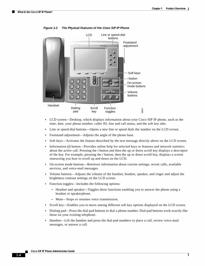
Figure 1-2 illustrates the physical features of the Cisco SIP IP phone.
1-3Cisco SIP IP Phone Administrator Guide
Chapter 1 Product OverviewWhat Is the Cisco SIP IP Phone?
Figure 1-2 The Physical Features of the Cisco SIP IP Phone
• LCD screen—Desktop, which displays information about your Cisco SIP IP phone, such as the time, date, your phone number, caller ID, line and call status, and the soft key tabs.
• Line or speed-dial buttons—Opens a new line or speed dials the number on the LCD screen.
• Footstand adjustment—Adjusts the angle of the phone base.
• Soft keys—Activates the feature described by the text message directly above on the LCD screen.
• Information (i) button—Provides online help for selected keys or features and network statistics about the active call. Pressing the i button and then the up or down scroll key displays a descriptor of the key. For example, pressing the i button, then the up or down scroll key, displays a screen instructing you how to scroll up and down on the LCD.
• On-screen mode buttons—Retrieves information about current settings, recent calls, available services, and voice-mail messages.
• Volume buttons—Adjusts the volume of the handset, headset, speaker, and ringer and adjust the brightness contrast settings on the LCD screen.
• Function toggles—Includes the following options:
– Headset and speaker—Toggles these functions enabling you to answer the phone using a headset or speakerphone.
– Mute—Stops or resumes voice transmission.
• Scroll key—Enables you to move among different soft key options displayed on the LCD screen.
• Dialing pad—Press the dial-pad buttons to dial a phone number. Dial-pad buttons work exactly like those on your existing telephone.
• Handset—Lift the handset and press the dial-pad numbers to place a call, review voice-mail messages, or answer a call.
HandsetDialing
padScrollkey
Function toggles
On-screenmode buttons
i button
Soft keys
LCD Line or speed-dialbuttons
3800
7
Footstandadjustment
Volumebuttons
1-4Cisco SIP IP Phone Administrator Guide
Chapter 1 Product OverviewWhat Is the Cisco SIP IP Phone?
BTXML SupportBasic Telephony eXtensible Markup Language (BTXML) is supported on the Cisco SIP IP phone. BTXML defines XML elements for controlling the user interface of an IP telephone. BTXML describes what information is displayed on the screen and how the user provides input using soft keys and hard keys. User interface control is internal to the phone; there is no external BTXML user interface control.
Cisco CallManager XML SupportThe Cisco SIP IP phone supports customer-written Cisco CallManager XML cards that can be accessed using buttons or soft keys on the phone. These cards can provide data such as stock quotes, calendars, and directory lookups. The XML cards can be accessed by the following methods:
• From the Services soft key, configured using the services_url parameter.
• By pressing the directory button and selecting External Directory, configured using the directory_url parameter.
• By downloading a bit-map to be used as the phone logo (branding), configured using the logo_url parameter.
See Chapter 3, “Managing Cisco SIP IP Phones,” for information about configuring these parameters.
The Cisco SIP IP phone supports Cisco CallManager XML up to version 3.0 but does not support the XML objects added in Cisco CallManager XML version 3.1, which are:
• CiscoIPPhoneIconMenu
• CiscoIPPhoneExecute
• CiscoIPPhoneError
• CiscoIPPhoneResponse
• SoftKeyItem
The following exceptions apply to the Cisco SIP IP phone:
• External directories cannot be appended to the main list of directories under the directory button. If external directories are provisioned for the Cisco SIP IP phone, they can be accessed by pressing the directory button and selecting the External Directory option.
• The Cisco SIP IP phone removes white space when the Cisco CallManager XML cards are displayed. Multiple spaces are consolidated into a single space.
• Setting x and y coordinates for the CiscoIPPhoneImage object is not supported. The image always appears at location 0,0. Centering of the image is not supported if x and y are set to –1.
• The Cisco SIP IP phone displays any valid title it receives. This differs from the Cisco CallManager phones in that the CiscoIPPhoneGraphicMenu object does not display a title even if it receives one and the CiscoIPPhoneImage object displays the previous menu item or “Services” rather than received titles.
• Cisco CallManager phones allow embedded carriage returns and line feeds in menu items. In the Cisco SIP IP phone, carriage returns and line feeds are discarded.
• The Cisco SIP IP phone always displays the full set of directory soft keys. For Cisco CallManager phones, the soft keys can change depending on what type of object it receives.
• A parameter is sent along with the initial request for a Services or Directory URL, which differentiates the Cisco SIP IP phone from other types of phones.
1-5Cisco SIP IP Phone Administrator Guide
Chapter 1 Product OverviewWhat Is the Cisco SIP IP Phone?
For more information about using XML on your Cisco SIP IP phone, refer to the following links or documents:
• IP Telephony at the following URL:
http://www.hotdispatch.com/cisco-ip-telephony
• Cisco CallManager Services Developer Kit at the following URL:
http://www.cisco.com/warp/public/570/avvid/voice_ip/cm_xml/cm_xmldown.shtml
• Developing Cisco IP Phone Services by Darrick Deel, Mark Nelson, and Anne Smith, ISBN 1-58705-060-9.
Supported FeaturesIn addition to the features illustrated in Figure 1-2 on page 1-4, the Cisco SIP IP phone also provides the following features.
Physical Features
• Adjustable ring tone.
• Hearing-aid compatible handset.
• Headset compatibility.
• Integrated two-port Ethernet switch that allows the telephone and a computer to share a single Ethernet jack.
• Direct connection to a 10BASE-T or 100BASE-T Ethernet (RJ-45) network (half- or full-duplex connections are supported).
• Large (4.25 x 3 in or 10.79 x 7.62 cm) display with adjustable contrast.
Network Features
• IP address assignment—Using Dynamic Host Configuration Protocol (DHCP) client or manually configuring using a local setup menu.
• Network startup using DHCP and TFTP.
• Telnet support—Allows the user to use Telnet to connect directly to the Cisco SIP IP phone to debug and troubleshoot the phone. See the “Managing Cisco SIP IP Phones” section on page 3-1 for more information on configuration parameters.
• Ping support—Allows the user to use ping to see if a Cisco SIP IP phone is operational and how long the response time is from the phone.
• Traceroute support—Allows the user to use traceroute to see the path that a Cisco SIP IP phone traverses in the route to its desired destination.
Configuration Features
The Cisco SIP IP phone provides the ability to do the following:
• Configure Ethernet port mode and speed
• Register with or unregister from a proxy server
1-6Cisco SIP IP Phone Administrator Guide
Chapter 1 Product OverviewWhat Is the Cisco SIP IP Phone?
• Register with or unregister from a backup proxy server
• Specify a TFTP boot directory
• Configure a label for phone identification display purposes
• Configure a name for caller identification purposes for each active line on a phone
• Configure a 12- or 24-hour user interface time display
• Lock and unlock the phone from the Settings menu
Codec and Protocol Support
• G.711 (u-law and a-law) and G.729a audio compression.
• In-band dual tone multifrequency (DTMF) support for touch-tone dialing.
• Out-of-band DTMF signaling for codecs that do not transport the DTMF signaling correctly (for example, G.729 or G.729a).
• Local (180 Ringing) or remote (183 Session Progress) call progress tone.
• Audio/Video Transport (AVT) payload type negotiation.
• Current date and time support via Simple Network Time Protocol (SNTP) and time zone and daylight saving time support.
• Call redirection information support via the Diversion header.
• Third-party call control via delayed media negotiation. A delayed media negotiation is one where the Session Description Protocol (SDP) information is not completely advertised in the initial call setup.
• Support for endpoints specified as fully qualified domain names (FQDNs) in the SDP.
• Remote reset and dial-plan update support (via the Event header in NOTIFY messages).
Refer to the “Supported Protocols” section on page 1-11 for additional supported protocols.
Dialing and Messaging Features
• Dial-plan support that enables automatic dialing and automatic generation of a secondary dial tone.
• Local directory configuration (save and recall) and automatic dial completion—Each time a call is successfully made or received, the number is stored in a local directory that is maintained on the phone. The maximum number of entries is 32. Entries are aged-out according to usage and age. The oldest entry that has been called the least number of times is overwritten first. This feature cannot be programmed by the user; however, up to 20 entries can be “locked” (via the Locked soft key) so that they will never be deleted.
• Message waiting indication (via unsolicited NOTIFY)—Lights to indicate that a new voice message is in a subscriber’s mailbox. If the subscriber listens to the message but does not save or delete the message, the light remains on. If a subscriber listens to the new message or messages, and saves or deletes them, the light goes off. The message waiting indicator is controlled by the voice-mail server. The indication will be saved over a phone upgrade or reboot.
• Speed dial to voice mail using the messages button.
• Do not disturb—Allows the user to instruct the system to intercept incoming calls during specified periods of time when the user does not want to be disturbed.
• Multiple directory numbers—Allows the Cisco SIP IP phone to have up to six directory numbers or lines.
1-7Cisco SIP IP Phone Administrator Guide
Chapter 1 Product OverviewWhat Is the Cisco SIP IP Phone?
• Call waiting (enabled)—Plays an audible tone to indicate that an incoming call is waiting. The user can then put the existing call on hold and accept the other call. The user can alternate between the two calls.
• Call waiting (disabled)—Allows the user to instruct the system to block call waiting calls during a specified period of time.
• Direct number dialing—Allows users to initiate or receive a call using a standard E.164 number format in a local, national, or international format.
• Direct URL dialing—Provides the ability to place a call using an e-mail address instead of a phone number.
• Caller ID blocking—Allows the user to instruct the system to block a phone number or e-mail address from phones that have caller identification capabilities.
• Anonymous call blocking—Allows the user to instruct the system to block any calls for which the identification is blocked.
• Three-way conferencing—Supports one phone conferencing with two other phones by providing mixing on the initiating phone. To set up a three-way conference call, see the “Making Conference Calls” section in Chapter 3 of the Cisco IP Phone Models 7960 and 7940 User Guide.
Call Options
• Call forward (network)—Allows the Cisco SIP IP phone user to request forwarding service from the network (via a third-party tool that enables this feature to be configured). When a call is placed to the user’s phone, it is redirected to the appropriate forward destination by the SIP proxy server.
• Call hold—Allows the Cisco SIP IP phone user (user A) to place a call (from user B) on hold. When user A places user B on hold, the two-way RTP voice path between user A and user B is temporarily disconnected, but the call session is still connected. When user A takes user B off hold, the two-way RTP voice path is reestablished.
• Call transfer—Allows the Cisco SIP IP phone user (user A) to transfer a call from one user (user B) to another user (user C). User A places user B on hold and calls user C. If user C accepts the transfer, a session is established between user B and user C and the session between user A and user B is terminated.
• Three-way calling—Allows a “bridged” three-way call. When a three-way call is established, the Cisco SIP IP phone through which the call is established acts as a bridge, mixing the audio media for the other parties.
Routing and Proxy Features
• User-defined proxy routing
The Route attribute of the template tag in the dial-plan template file can be used to indicate to which proxy (default, emergency, FQDN) the call should be initially routed. For example, to configure an emergency proxy, specify the value of the Route attribute as “emergency.”
• Backup SIP proxy
When the primary proxy does not respond to the INVITE message sent by the Cisco SIP IP Phone after the configured number of retries, the Cisco SIP IP Phone sends the INVITE to the backup proxy. This is independent from the proxy defined in the Route attribute in the dial-plan template used.
1-8Cisco SIP IP Phone Administrator Guide
Chapter 1 Product OverviewWhat Is the Cisco SIP IP Phone?
The Cisco SIP IP phone attempts to register with the backup proxy. All interactions with the backup proxy, such as authentication challenges, are treated the same as the interactions with the primary proxy.
The backup proxy is used only with new INVITE messages that fail to communicate with the primary proxy. Once the backup proxy is used, it is active for the duration of the call.
The location of the backup SIP proxy can be defined as an IP address in the default configuration file. Refer to the proxy_backup and proxy_backup_port parameters in the “Modifying the SIP Settings” section on page 3-6 .
• Emergency SIP proxy
An optional emergency SIP proxy can be configured with the Route attribute of the template tag in the dial-plan template file.
When an emergency SIP proxy is configured and a call is initiated, the phone generates an INVITE message to the address specified in the proxy_emergency parameter. The emergency proxy is used for the call duration.
The location of the emergency proxy can be defined as an IP address in the default configuration file. Refer to the proxy_emergency and proxy_emergency_port parameters in the “Modifying the SIP Settings” section on page 3-6.
• Support of DNS SRV
The Domain Name Server (DNS SRV) is used to locate servers for a given service.
SIP on Cisco SIP IP phones uses a DNS SRV query to determine the IP address of the SIP proxy or redirect server. The query string generated is in compliance with RFC 2782 and prepends the protocol label with an underscore (_), as in “_protocol._transport.” The addition of the underscore reduces the risk of the same name being used for unrelated purposes.
In compliance with RFC 2782 and the draft-ietf-sip-srv-01 specification, the system can remember multiple IP addresses and use them properly. In the draft-ietf-sip-srv-01 specification, it is assumed that all proxies returned for the SRV record are equivalent such that the phone can register with any of the proxies and initiate a call using any other proxy.
• Configurable voice activity detection
Voice activity detection (VAD) can be enabled or disabled with the enable_vad parameter. Use a value of 0 to disable and a value of 1 to enable. Refer to the enable_vad parameter in “Modifying the SIP Settings” section on page 3-6.
• Distinctive alerting
If the INVITE message contains an Alert-Info header, distinctive ringing is invoked. The format of the header is “Alert-info: x”. The value of “x” can be any number. This header is received only by the phone and is not generated by the phone.
Distinctive ringing is supported when the phone is idle or during a call. In the idle mode, the phone rings with a different cadence. The selected ringing type plays twice with a short pause in between. In call-waiting mode, two short beeps are generated instead of one long beep.
• Network Address Translation and outbound proxy
Network Address Translation (NAT) can be enabled or disabled with the nat_enable parameter. You can configure the address of the NAT or firewall server using the nat_address parameter.
You can configure the IP address and port number of the outbound proxy server. When outbound proxy is enabled, all SIP requests are sent to the outbound proxy server instead of to the proxyN_address. All responses continue to reconcile the normal Via processing rules. The media stream is not routed through the outbound proxy.
1-9Cisco SIP IP Phone Administrator Guide
Chapter 1 Product OverviewWhat Is the Cisco SIP IP Phone?
NAT and outbound proxy modes can be independently enabled or disabled. The received= tag is added to the Via header of all responses if there is no received= tag in the uppermost Via header and the source IP address is different from the IP address in the uppermost Via header. Responses are sent back to the source under the following conditions:
– If a received= tag is in the uppermost Via header, the response is sent back to the IP address contained in the received= tag.
– If there is no received= tag and the IP address in the uppermost Via header is different from the source IP address, the response is sent back to the source IP address. Otherwise the response is sent back to the IP address in the uppermost Via header.
Note For information on how to use the standard telephony features and URL dialing, refer to the documents listed in the “Related Documentation” section on page x.
Character Support
The Cisco SIP IP phone supports the ISO 8859-1 Latin1 characters. The following languages are supported:
• French (fr), Spanish (es), Catalan (ca), Basque (eu), Portuguese (pt), Italian (it), Albanian (sq), Rhaeto-Romanic (rm), Dutch (nl), German (de), Danish (da), Swedish (sv), Norwegian (no), Finnish (fi), Faroese (fo), Icelandic (is), Irish (ga), Scottish (gd), English (en), Afrikaans (af), and Swahili (sw).
The following languages are not supported:
• Zulu (zu) and other Bantu languages using Latin Extended-B letters, Arabic in North Africa, and Guarani (gn) missing GEIUY with tilde (~).
Note The XML cards, information text, and menus are all in English. These items are built into the phone image and cannot be changed.
ISO 8859-1 Latin1 characters can be used in the following areas:
• Caller ID information. When a SIP message is received with ISO 8859-1 Latin1 characters in the caller ID strings, those caller ID strings are displayed on the Cisco SIP IP phone LCD with the correct ISO 8859-1 Latin1 characters.
• Services menu applications written in CMXML. The customer can develop language-specific applications for a particular region. For example, an application that displayed the current weather in Sweden using Swedish language characters can be displayed on the Cisco SIP IP phone. If the customer develops the same application for a Spanish town, the application could be translated into Spanish.
• Line key labels. The line keys can be configured to support the Latin1 characters. The line key name can be specified in the configuration file, and it will be displayed correctly. The Latin1 characters cannot be used in the lineX_name, but can be used in the lineX_shortname and lineX_displayname. If the proxy supports Latin1 characters in the To/From headers, they can be used in the lineX_name parameter as well.
1-10Cisco SIP IP Phone Administrator Guide
Chapter 1 Product OverviewWhat Is the Cisco SIP IP Phone?
Supported ProtocolsThe Cisco SIP IP phone supports the following standard protocols:
• Domain Name Server (DNS)—Used in the Internet for translating names of network nodes into addresses. SIP uses DNS to resolve the host names of endpoints to IP addresses.
• Dynamic Host Configuration Protocol (DHCP)—Used to dynamically allocate and assign IP addresses. DHCP allows you to move network devices from one subnet to another without administrative attention. If using DHCP, you can connect Cisco SIP IP phones to the network and become operational without having to manually assign an IP address and additional network parameters.
The Cisco SIP IP phone complies with the DHCP specifications documented in RFC 2131. By default, Cisco SIP IP phones are DHCP-enabled.
• Internet Control Message Protocol (ICMP)—A network layer Internet protocol that enables hosts to send error or control messages to other hosts. ICMP also provides other information relevant to IP packet processing.
The Cisco SIP IP phone supports ICMP as it is documented in RFC 792.
• Internet Protocol (IP)—A network layer protocol that sends datagram packets between nodes on the Internet. IP also provides features for addressing, type-of-service (ToS) specification, fragmentation and reassembly, and security.
The Cisco SIP IP phone supports IP as it is defined in RFC 791.
• Real-Time Transport Protocol (RTP)—Transports real-time data (such as voice data) over data networks. RTP also has the ability to obtain quality of service (QoS) information.
The Cisco SIP IP phone supports RTP as a media channel.
• Session Description Protocol (SDP)—An ASCII-based protocol that describes multimedia sessions and their related scheduling information.
The Cisco SIP IP phone uses SDP for session description.
• Simple Network Time Protocol (SNTP)—Sychronizes computer clocks on an IP network. The Cisco SIP IP phones use SNTP for their date and time support.
• Transmission Control Protocol (TCP)—Provides a reliable byte-stream transfer service between two endpoints on an internet. The Cisco SIP IP phone supports TCP for Telnet sessions only.
• Trivial File Transfer Protocol (TFTP)—Allows files to be transferred from one computer to another over a network. The Cisco SIP IP phone uses TFTP to download configuration files and software updates.
• User Datagram Protocol (UDP)—A simple protocol that exchanges data packets without acknowledgments or guaranteed delivery. SIP can use UDP as the underlying transport protocol. If UDP is used, retransmissions are used to ensure reliability. UDP fragmentation is supported.
The Cisco SIP IP phone supports UDP as it is defined in RFC 768 for SIP signaling.
• Hypertext Transfer Protocol (HTTP)—The phone contains limited support for HTTP 1.1. The Cisco SIP IP phone uses HTTP to retrieve Cisco CallManager XML files.
1-11Cisco SIP IP Phone Administrator Guide
Chapter 1 Product OverviewPrerequisites
PrerequisitesFor the Cisco SIP IP phone to successfully operate as a SIP endpoint in your network, your network must meet the following requirements:
• A working IP network is established.
For more information about configuring IP, refer to the Cisco IOS IP Configuration Guide, Release 12.2.
• VoIP is configured on your Cisco routers.
For more information about configuring VoIP, refer to the Cisco IOS Voice, Video, and Fax Configuration Guide, Release 12.2, for the appropriate access platform. For more information about configuring SIP VoIP, refer to the “Configuring SIP for VoIP” chapter.
• VoIP gateways are configured for SIP.
• A TFTP server is active and contains the latest Cisco SIP IP phone firmware image in its root directory.
• A proxy server is active and configured to receive and forward SIP messages.
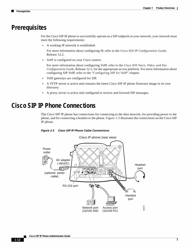
Cisco SIP IP Phone ConnectionsThe Cisco SIP IP phone has connections for connecting to the data network, for providing power to the phone, and for connecting a headset to the phone. Figure 1-3 illustrates the connections on the Cisco SIP IP phone.
Figure 1-3 Cisco SIP IP Phone Cable Connections
Handsetport
Headsetport
Cisco IP phone (rear view)
6247
2
Poweroutlet
RS-232 port
(optional powercable)
AC adapter(-48VDC)
Access port(10/100 PC)
Network port(10/100 SW)
1-12Cisco SIP IP Phone Administrator Guide
Chapter 1 Product OverviewCisco SIP IP Phone Connections
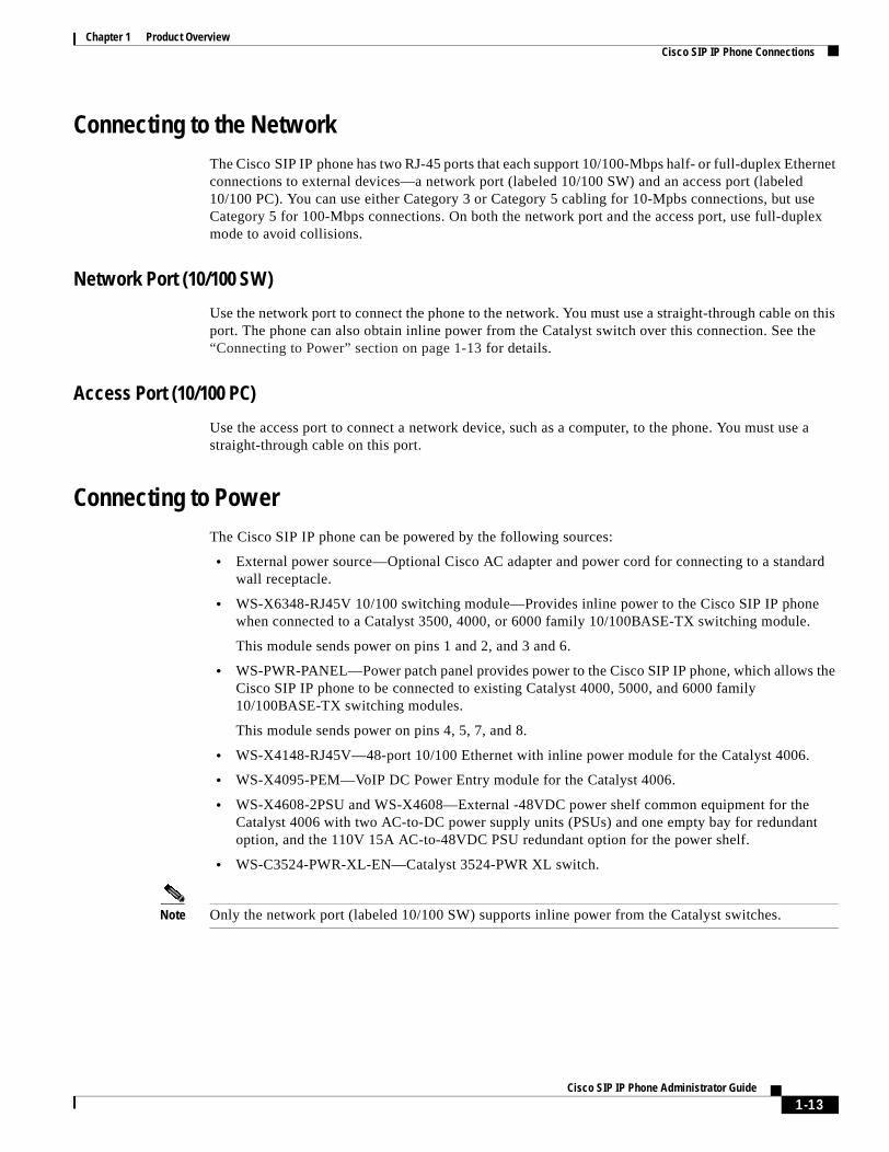
Connecting to the NetworkThe Cisco SIP IP phone has two RJ-45 ports that each support 10/100-Mbps half- or full-duplex Ethernet connections to external devices—a network port (labeled 10/100 SW) and an access port (labeled 10/100 PC). You can use either Category 3 or Category 5 cabling for 10-Mpbs connections, but use Category 5 for 100-Mbps connections. On both the network port and the access port, use full-duplex mode to avoid collisions.
Network Port (10/100 SW)
Use the network port to connect the phone to the network. You must use a straight-through cable on this port. The phone can also obtain inline power from the Catalyst switch over this connection. See the “Connecting to Power” section on page 1-13 for details.
Access Port (10/100 PC)
Use the access port to connect a network device, such as a computer, to the phone. You must use a straight-through cable on this port.
Connecting to PowerThe Cisco SIP IP phone can be powered by the following sources:
• External power source—Optional Cisco AC adapter and power cord for connecting to a standard wall receptacle.
• WS-X6348-RJ45V 10/100 switching module—Provides inline power to the Cisco SIP IP phone when connected to a Catalyst 3500, 4000, or 6000 family 10/100BASE-TX switching module.
This module sends power on pins 1 and 2, and 3 and 6.
• WS-PWR-PANEL—Power patch panel provides power to the Cisco SIP IP phone, which allows the Cisco SIP IP phone to be connected to existing Catalyst 4000, 5000, and 6000 family 10/100BASE-TX switching modules.
This module sends power on pins 4, 5, 7, and 8.
• WS-X4148-RJ45V—48-port 10/100 Ethernet with inline power module for the Catalyst 4006.
• WS-X4095-PEM—VoIP DC Power Entry module for the Catalyst 4006.
• WS-X4608-2PSU and WS-X4608—External -48VDC power shelf common equipment for the Catalyst 4006 with two AC-to-DC power supply units (PSUs) and one empty bay for redundant option, and the 110V 15A AC-to-48VDC PSU redundant option for the power shelf.
• WS-C3524-PWR-XL-EN—Catalyst 3524-PWR XL switch.
Note Only the network port (labeled 10/100 SW) supports inline power from the Catalyst switches.
1-13Cisco SIP IP Phone Administrator Guide
Chapter 1 Product OverviewThe Cisco SIP IP Phone with a Catalyst Switch
Using a HeadsetThe Cisco SIP IP phone supports a four- or six-wire headset jack. Specifically, the Cisco SIP IP phone supports the following Plantronics headset models:
• Tristar Monaural
• Encore Monaural H91
• Encore Binaural H101
The volume and mute controls also adjust volume to the earpiece and mute the speech path of the headset. The headset activation key is located on the front of the Cisco SIP IP phone.
Note When using a headset, an amplifier is not required. However, a coil cord is required to connect the headset to the headset port on the back of your Cisco IP Phone 7960/7940. For information on ordering compatible headsets and coil cords for the Cisco IP Phone 7960/7940, go to the following URL:
http://cisco.getheadsets.com or http://vxicorp.com/cisco
The Cisco SIP IP Phone with a Catalyst SwitchTo function in the IP telephony network, the Cisco SIP IP phone must be connected to a networking device, such as a Catalyst switch, to obtain network connectivity.
The Cisco SIP IP phone has an internal Ethernet switch, which enables it to switch traffic coming from the phone, access port, and network port.
If a computer is connected to the access port, packets traveling to and from the computer and to and from the phone share the same physical link to the switch and the same port on the switch.
This configuration has the following implications for the VLAN configuration on the network:
• The current VLANs might be configured on an IP subnet basis, and additional IP addresses might not be available to assign the phone to a port so that it belongs to the same subnet as other devices (PC) connected to the same port.
• Data traffic present on the VLAN supporting phones might reduce the quality of VoIP traffic.
You can resolve these issues by isolating the voice traffic onto a separate VLAN on each of the ports connected to a phone. The switch port configured for connecting a phone would have separate VLANs configured for carrying the following traffic:
• Voice traffic to and from the Cisco SIP IP phone (auxiliary VLAN).
• Data traffic to and from the PC connected to the switch through the access port of the Cisco SIP IP phone (native VLAN).
Isolating the phones on a separate, auxiliary VLAN increases the quality of the voice traffic and allows a large number of phones to be added to an existing network where there are not enough IP addresses.
For redundancy, you can use the Cisco AC adapter even if you are using inline power from the Catalyst switches. The Cisco SIP IP phone can share the power load being used from the inline power and external power source. If either the inline power or the external power goes down, the phone can switch entirely to the other power source.
1-14Cisco SIP IP Phone Administrator Guide

Chapter 1 Product OverviewThe Cisco SIP IP Phone with a Catalyst Switch
To use this redundancy feature you must set the inline power mode to auto on the Cisco Catalyst switch. Next, connect the unpowered Cisco SIP IP phone to the network. After the phone powers up, connect the external power supply to the phone.
For more information, refer to the documentation included with the Catalyst switch or available online at the following URL:
http://www.cisco.com/univercd/home/index.htm
1-15Cisco SIP IP Phone Administrator Guide

Chapter 1 Product OverviewThe Cisco SIP IP Phone with a Catalyst Switch
1-16Cisco SIP IP Phone Administrator Guide

C H A P T E R 2
Getting Started with Your Cisco SIP IP PhoneThis chapter explains the Cisco SIP IP phone initialization and the process that you should follow to install and connect the Cisco SIP IP phone. It provides the following sections:
• Overview of the Initialization Process, page 2-1
• Installing the Cisco SIP IP Phone, page 2-2
• Verifying Startup, page 2-14
• Using the Cisco SIP IP Phone Menu Interface, page 2-15
• Reading the Cisco SIP IP Phone Icons, page 2-15
• Customizing the Cisco SIP IP Phone Ring Types, page 2-17
• Creating Dial Plans, page 2-17
Overview of the Initialization ProcessThe initialization process of the Cisco SIP IP phone establishes network connectivity and makes the phone operational in your IP network. Once you connect your phone to the network and to an electrical supply, the phone begins its initialization process. During the initialization process, the following events take place:
1. The stored image is loaded.
The Cisco SIP IP phone has nonvolatile Flash memory in which it stores the firmware images, user-defined preferences, and permanent factory information about the phone.
During initialization, the phone runs a bootstrap loader that loads and executes the phone image stored in Flash memory.
2. The VLAN is configured.
If the Cisco SIP IP phone is connected to a Catalyst switch, the switch notifies the phone of the voice VLAN defined on the switch. The phone needs to know its VLAN membership before it can proceed with the Dynamic Host Configuration Protocol (DHCP) request for its IP settings (if using DHCP).
3. An IP address is acquired.
If the Cisco SIP IP phone is using DHCP to obtain the IP settings, the phone queries the DHCP server. If the phone is not using DHCP, the phone uses IP settings that are stored in Flash memory.
2-1Cisco SIP IP Phone Administrator Guide
Chapter 2 Getting Started with Your Cisco SIP IP PhoneInstalling the Cisco SIP IP Phone
4. The TFTP server is contacted.
The TFTP server contains the latest Cisco SIP IP phone firmware image and the dual boot file (OS79XX.TXT) that enables the phone to automatically determine and initialize the VoIP environment in which it is being installed.
If the phone is using the TFTP server to obtain its SIP parameters, there should also be a configuration file or files on the TFTP server that the phone will request and download. In the configuration file or files, SIP parameters that are required by the phone to operate in a SIP VoIP environment are defined. If the phone is not obtaining its SIP parameters via the TFTP server, the phone uses SIP settings that are stored in Flash memory.
5. The firmware version is verified.
If the phone is obtaining its SIP parameters via a TFTP server, the configuration files are requested. If the phone determines that the image defined in a configuration file differs from the image it has stored in Flash memory, it performs a firmware upgrade. When performing a firmware upgrade, the phone downloads the firmware image from the TFTP server, programs the image into Flash memory, and reboots.
Installing the Cisco SIP IP PhoneThis section contains information on how to install Cisco SIP IP phones in your IP network. Before getting started, read over the information in this section carefully.
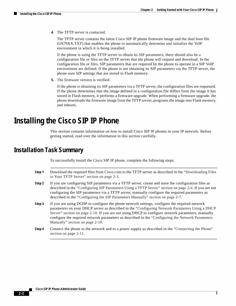
Installation Task SummaryTo successfully install the Cisco SIP IP phone, complete the following steps:
Step 1 Download the required files from Cisco.com to the TFTP server as described in the “Downloading Files to Your TFTP Server” section on page 2-3.
Step 2 If you are configuring SIP parameters via a TFTP server, create and store the configuration files as described in the “Configuring SIP Parameters Using a TFTP Server” section on page 2-4. If you are not configuring the SIP parameters via a TFTP server, manually configure the required parameters as described in the “Configuring the SIP Parameters Manually” section on page 2-7.
Step 3 If you are using DCHP to configure the phone network settings, configure the required network parameters on your DHCP server as described in the “Configuring Network Parameters Using a DHCP Server” section on page 2-10. If you are not using DHCP to configure network parameters, manually configure the required network parameters as described in the “Configuring the Network Parameters Manually” section on page 2-10.
Step 4 Connect the phone to the network and to a power supply as described in the “Connecting the Phone” section on page 2-11.
2-2Cisco SIP IP Phone Administrator Guide
Chapter 2 Getting Started with Your Cisco SIP IP PhoneInstalling the Cisco SIP IP Phone
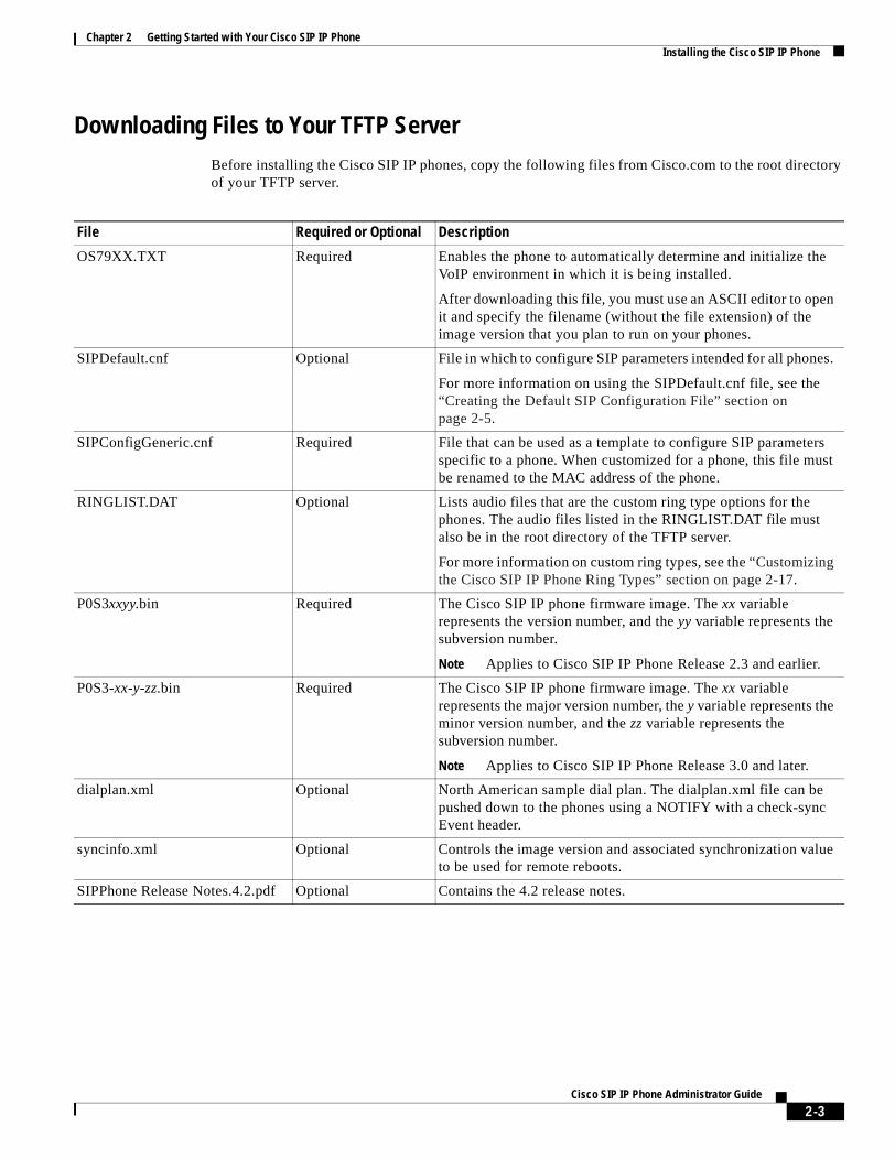
Downloading Files to Your TFTP ServerBefore installing the Cisco SIP IP phones, copy the following files from Cisco.com to the root directory of your TFTP server.
File Required or Optional Description
OS79XX.TXT Required Enables the phone to automatically determine and initialize the VoIP environment in which it is being installed.
After downloading this file, you must use an ASCII editor to open it and specify the filename (without the file extension) of the image version that you plan to run on your phones.
SIPDefault.cnf Optional File in which to configure SIP parameters intended for all phones.
For more information on using the SIPDefault.cnf file, see the “Creating the Default SIP Configuration File” section on page 2-5.
SIPConfigGeneric.cnf Required File that can be used as a template to configure SIP parameters specific to a phone. When customized for a phone, this file must be renamed to the MAC address of the phone.
RINGLIST.DAT Optional Lists audio files that are the custom ring type options for the phones. The audio files listed in the RINGLIST.DAT file must also be in the root directory of the TFTP server.
For more information on custom ring types, see the “Customizing the Cisco SIP IP Phone Ring Types” section on page 2-17.
P0S3xxyy.bin Required The Cisco SIP IP phone firmware image. The xx variable represents the version number, and the yy variable represents the subversion number.
Note Applies to Cisco SIP IP Phone Release 2.3 and earlier.
P0S3-xx-y-zz.bin Required The Cisco SIP IP phone firmware image. The xx variable represents the major version number, the y variable represents the minor version number, and the zz variable represents the subversion number.
Note Applies to Cisco SIP IP Phone Release 3.0 and later.
dialplan.xml Optional North American sample dial plan. The dialplan.xml file can be pushed down to the phones using a NOTIFY with a check-sync Event header.
syncinfo.xml Optional Controls the image version and associated synchronization value to be used for remote reboots.
SIPPhone Release Notes.4.2.pdf Optional Contains the 4.2 release notes.
2-3Cisco SIP IP Phone Administrator Guide
Chapter 2 Getting Started with Your Cisco SIP IP PhoneInstalling the Cisco SIP IP Phone
Configuring SIP Parameters
Note This section describes how to configure the basic SIP parameters that are required for the phone to operate in a SIP VoIP environment. For a complete list of the SIP parameters that you can configure, see the “Modifying the SIP Settings” section on page 3-6.
The SIP parameters are those parameters that a Cisco SIP IP phone needs in order to operate in a SIP VoIP environment. You can configure SIP parameters via a TFTP server, or you can manually configure the parameters on a phone-by-phone basis after connecting the phones.
When the phone initializes, it loads the parameters stored in Flash memory. After loading the parameters stored in Flash memory, the phone requests the default configuration file from the TFTP server. If the default configuration file has been configured and stored in the root directory of the TFTP server, the phone reads the parameters defined in the file and stores those parameters that differ in Flash memory. The phone then requests its phone-specific configuration file.
If the phone-specific configuration file has been configured and placed on the TFTP server (in the root directory or a subdirectory), the phone reads the parameters defined in the file and stores those parameters that differ in Flash memory.
Therefore, when configuring SIP parameters, remember the following:
• Parameters defined in the default configuration file override the values stored in Flash memory.
• Parameters defined in the phone-specific configuration file override the values specified in the default configuration file.
• Parameters entered locally are used by the phone until the next reboot (if a phone-specific configuration file exists).
• If you choose not to configure the phone via a TFTP server, you must manage the phone locally.
Configuring SIP Parameters Using a TFTP Server
If you are configuring SIP parameters using a TFTP server, you must use configuration files.
There are two configuration files that you can use to define the SIP parameters: the default configuration file (optional) and the phone-specific configuration file (required). If you choose to use a default configuration file, you must store the file in the root directory of your TFTP server. Phone-specific configuration files can be stored in the root directory or in a subdirectory in which all phone-specific configuration files are stored.
Except for parameters used to define the lines and users on a phone, all other SIP parameters can be defined in either the default configuration file or the phone-specific configuration file. However, for network control and maintenance purposes, we recommend that you define the parameters that you want to apply to all phones in the default configuration file (SIPDefault.cnf). Phone-specific parameters should only be defined via a phone-specific configuration file or be configured manually. Phone-specific parameters should not be defined in the default configuration file.
2-4Cisco SIP IP Phone Administrator Guide

Chapter 2 Getting Started with Your Cisco SIP IP PhoneInstalling the Cisco SIP IP Phone
Configuration File Guidelines
When modifying the default configuration file and creating the phone-specific configuration files, adhere to the following guidelines and requirements:
• SIP parameters specified in the default configuration file (SIPDefault.cnf) override those parameters stored in Flash memory. Parameters specified in a phone-specific configuration file override those stored in Flash memory and those specified in the default configuration file.
• The name of each phone-specific configuration file is unique and is based on the MAC address of the phone.
The format of the filename must be SIPXXXXYYYYZZZZ.cnf, where XXXXYYYYZZZZ is the MAC address of the phone. The MAC address must be in uppercase, and the cnf extension must be in lowercase (for example, SIP00503EFFD842.cnf).
Note The MAC address of a phone is identified on the middle sticker adhered to the base of the phone and can also be viewed on the Network Configuration menu.
• The default configuration file must be stored in the root directory of the TFTP server. The phone-specific configuration file can be stored in the root directory or in a subdirectory in which all phone-specific configuration files are located.
• Each line in the configuration files must use the following format:
variable-name : value ; optional comments
• Use colons to separate variable names and values.
• Only one value can be associated with a variable.
• The variable and value can contain white space before or after them and can contain any characters. However, if white spaces are needed within the value, the value must be enclosed in single or double quotes. If the value is enclosed in quotes, the end quote must be the same as the start quote.
• After the value, you can include optional comments. Use the semicolon (;) and pound (#) delimiters to distinguish the comments.
• Blank lines are allowed.
• Comment lines are allowed.
• Variable names are not case sensitive.
• Only one variable can be set per line.
• Distinguish the end of a line using <lf> or <cr><lf>.
• The variable and value must be on the same line and cannot break the line.
• Except for parameters used to defined the lines and users on a phone, all other SIP parameters can be defined in either the default configuration file or the phone-specific configuration file. However, for network control and maintenance purposes, Cisco recommends that you define the parameters that you want to apply to all phones in the default configuration file (SIPDefault.cnf).
Creating the Default SIP Configuration File
In the default configuration file (SIPDefault.cnf), Cisco recommends that you define the SIP parameters that will be common to all of your phones such as the image_version parameter and call environment parameters (for example, you will want to consider if the phones are required to register with a proxy server, and which codec the phones will use when initiating a call).
2-5Cisco SIP IP Phone Administrator Guide
Chapter 2 Getting Started with Your Cisco SIP IP PhoneInstalling the Cisco SIP IP Phone
By maintaining these parameters in the default configuration file, you can perform global changes, such as upgrading the image version, without having to modify the phone-specific configuration file for each phone.
Before You Begin
• Ensure that you have downloaded the SIPDefault.cnf file from Cisco.com to the root directory of your TFTP server.
• Review the guidelines documented in the “Configuration File Guidelines” section on page 2-5.
• For a complete list of the SIP parameters that you can configure, see the “Modifying the SIP Settings” section on page 3-6.
Procedure
Step 1 Using an ASCII editor, open the SIPDefault.cnf file and define values for the following SIP global parameters:
• image_version—(Required) Firmware version that the Cisco SIP IP phone should run.
Enter the name of the image version (as it is released by Cisco). Do not enter the extension. You cannot change the image version by changing the filename, because the version is also built into the file header. Trying to change the image version by changing the filename causes the firmware to fail when it compares the version in the header against the filename.
• proxy1_address—(Required) IP address of the primary SIP proxy server that will be used by the phones.
• tftp_cfg_dir—(Required if phone-specific configuration files are located in a subdirectory) Path to the TFTP subdirectory in which phone-specific configuration files are stored.
Step 2 Save the file with the same filename, SIPDefault.cnf, to the root directory of your TFTP server.
The following is an example of a default SIP configuration file:
#Image Versionimage_version:P0S3-xx-y-zz ;
#Proxy server addressproxy1_address: 192.168.1.1 ;
#Subdirectory config file locationtftp_cfg_dir: /tftpboot/configs/sipphone
Creating the Phone-Specific SIP Configuration File
In the phone-specific SIP configuration file, define the parameters that are specific to a phone, such as the lines configured on a phone and the users defined for those lines.
Before You Begin
• Review the guidelines documented in the “Configuration File Guidelines” section on page 2-5.
• Line parameters (those identified as linex) define a line on the phone. If you configure a line to use an e-mail address, that line can be called only by using an e-mail address. Similarly, if you configure a line to use a number, that line can be called only by using the number. Each line can have a different proxy configured.
2-6Cisco SIP IP Phone Administrator Guide
Chapter 2 Getting Started with Your Cisco SIP IP PhoneInstalling the Cisco SIP IP Phone
• For a complete list of the SIP parameters that you can configure, see the “Modifying the SIP Settings” section on page 3-6.
Procedure
Step 1 Using an ASCII editor, create a phone-specific configuration file for each phone that you plan to install. In the phone-specific configuration file, define values for the following SIP parameters (where x is a number 1 through 6):
• linex_name—(Required) Number or e-mail address used when registering. When entering a number, enter the number without any dashes. For example, enter 555-1212 as 5551212. When entering an e-mail address, enter the e-mail ID without the host name.
• linex_authname—(Required when registration is enabled and the proxy server requires authentication) Name used by the phone for authentication if a registration is challenged by the proxy server during initialization. If a value is not configured for the linex_authname parameter when registration is enabled, the default name is used. The default name is UNPROVISIONED.
• linex_password—(Required when registration is enabled and the proxy server requires authentication) Password used by the phone for authentication if a registration is challenged by the proxy server during initialization. If a value is not configured for the linex_password parameter when registration is enabled, the default logical password is used. The default logical password is UNPROVISIONED.
Step 2 Save the file to your TFTP server (in the root directory or in a subdirectory that contains all the phone-specific configuration files). Name the file SIPXXXXYYYYZZZZ.cnf where XXXXYYYYZZZZ is the MAC address of the phone. The MAC address must be in uppercase and the extension, cnf, must be in lowercase (for example, SIP00503EFFD842.cnf).
The following is an example of a phone-specific SIP configuration file:
; Line 1 phone numberline1_name : 5551212
; Line 1 name for authentication with proxy serverline1_authname : 5551212
; Line 1 authentication name passwordline1_password : password
Configuring the SIP Parameters Manually
If you did not configure the SIP parameters via a TFTP server, you must manually configure them after you have connected the phone as described in the “Connecting the Phone” section on page 2-11.
Before You Begin
• Connect your phone as described in the “Connecting the Phone” section on page 2-11.
• Unlock configuration mode as described in the “Locking Configuration Mode” section on page 3-3. By default, the SIP parameters are locked to ensure that end users cannot modify settings that might affect their call capabilities.
• Review the guidelines on using the Cisco SIP IP phone menus documented in the“Using the Cisco SIP IP Phone Menu Interface” section on page 2-15.
2-7Cisco SIP IP Phone Administrator Guide
Chapter 2 Getting Started with Your Cisco SIP IP PhoneInstalling the Cisco SIP IP Phone
• When configuring the Preferred Codec and Out of Band DTMF parameters, press the Change soft key until the option that you desire is displayed and then press the Save soft key.
• After making your changes, relock configuration mode as described in the “Locking Configuration Mode” section on page 3-3.
• For a complete list of the SIP parameters that you can configure, see the “Modifying the SIP Settings” section on page 3-6.
Procedure
Step 1 Press the settings key. The Settings menu is displayed.
Step 2 Highlight SIP Configuration. The SIP Configuration menu is displayed.
Step 3 Highlight Line 1 Settings.
Step 4 Press the Select soft key. The Line 1 Configuration menu is displayed.
Step 5 Highlight and press the Select soft key to configure the parameters shown in Table 2-1:
Table 2-1 Manual SIP Configuration Parameters
Parameter Required or Optional Description
Name Required Number or e-mail address used when registering. When entering a number, enter the number without any dashes. For example, enter 555-1212 as 5551212. When entering an e-mail address, enter the e-mail ID without the host name.
Shortname Optional Name or number associated with the linex_name as you want it to display on the phone’s LCD if the linex_name value exceeds the display area. For example, if the linex_name value is the phone number 111-222-333-4444, you can specify 34444 for this parameter to have 34444 display on the LCD instead. Alternately, if the value for the linex_name parameter is the e-mail address “[email protected],” you can specify the “username” to have just the username appear on the LCD instead. This parameter is used for display purposes only. If a value is not specified for this parameter, the value in the Name variable is displayed.
Authentication Name
Required when registration is enabled
Name used by the phone for authentication if a registration is challenged by the proxy server during initialization. If a value is not configured for the Authentication Name parameter when registration is enabled, the default name is used. The default name is UNPROVISIONED.
Authentication Password
Required when registration is enabled
Password used by the phone for authentication if a registration is challenged by the proxy server during initialization. If a value is not configured for the Authentication Password parameter when registration is enabled, the default logical password is used. The default password is UNPROVISIONED.
2-8Cisco SIP IP Phone Administrator Guide
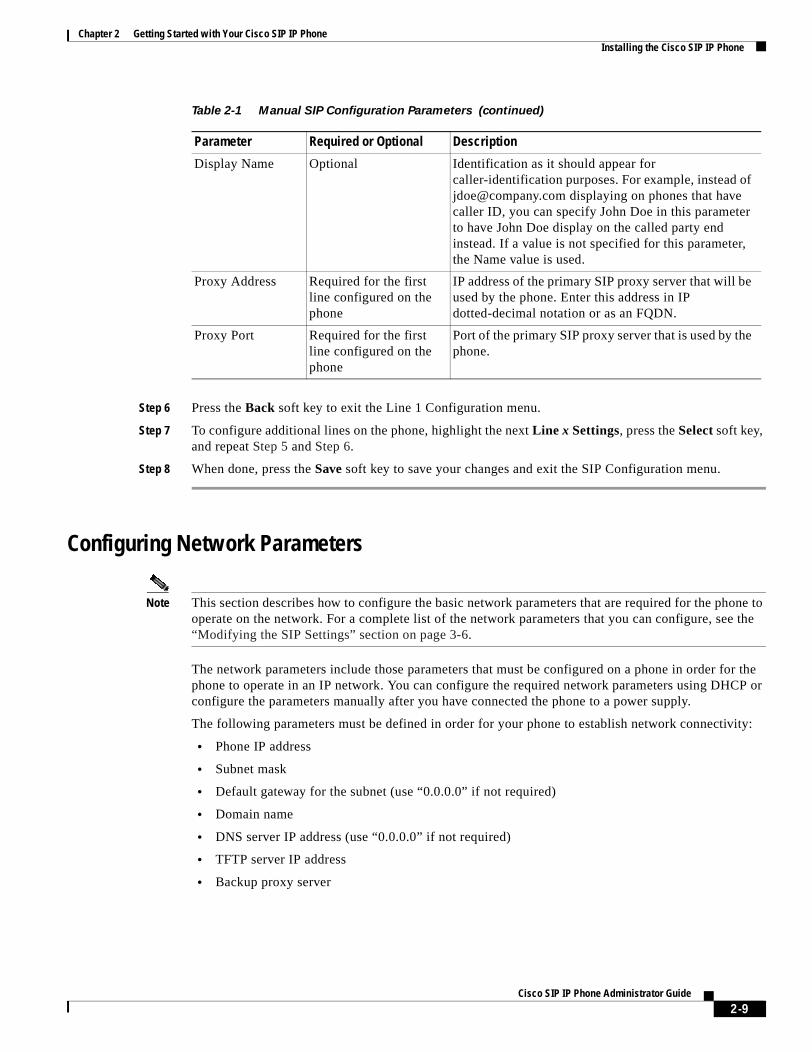
Chapter 2 Getting Started with Your Cisco SIP IP PhoneInstalling the Cisco SIP IP Phone
Step 6 Press the Back soft key to exit the Line 1 Configuration menu.
Step 7 To configure additional lines on the phone, highlight the next Line x Settings, press the Select soft key, and repeat Step 5 and Step 6.
Step 8 When done, press the Save soft key to save your changes and exit the SIP Configuration menu.
Configuring Network Parameters
Note This section describes how to configure the basic network parameters that are required for the phone to operate on the network. For a complete list of the network parameters that you can configure, see the “Modifying the SIP Settings” section on page 3-6.
The network parameters include those parameters that must be configured on a phone in order for the phone to operate in an IP network. You can configure the required network parameters using DHCP or configure the parameters manually after you have connected the phone to a power supply.
The following parameters must be defined in order for your phone to establish network connectivity:
• Phone IP address
• Subnet mask
• Default gateway for the subnet (use “0.0.0.0” if not required)
• Domain name
• DNS server IP address (use “0.0.0.0” if not required)
• TFTP server IP address
• Backup proxy server
Display Name Optional Identification as it should appear for caller-identification purposes. For example, instead of [email protected] displaying on phones that have caller ID, you can specify John Doe in this parameter to have John Doe display on the called party end instead. If a value is not specified for this parameter, the Name value is used.
Proxy Address Required for the first line configured on the phone
IP address of the primary SIP proxy server that will be used by the phone. Enter this address in IP dotted-decimal notation or as an FQDN.
Proxy Port Required for the first line configured on the phone
Port of the primary SIP proxy server that is used by the phone.
Table 2-1 Manual SIP Configuration Parameters (continued)
Parameter Required or Optional Description
2-9Cisco SIP IP Phone Administrator Guide
Chapter 2 Getting Started with Your Cisco SIP IP PhoneInstalling the Cisco SIP IP Phone
When configuring the network parameters of an IP phone, adhere to the following guidelines:
• Use 0.0.0.0 for unused IP addresses.
• You can use 0.0.0.0 for the subnet mask only if the default gateway is also 0.0.0.0.
• The TFTP server must have a nonzero IP address.
• The default gateway must be on the same subnet as the phone.
• The default gateway can be 0.0.0.0 only if the TFTP or DNS server is on the same subnet as the phone.
Note By default, DHCP is enabled on your phone. Before you can manually configure the network parameters, you must disable DHCP after connecting your phone to a power supply.
Configuring Network Parameters Using a DHCP Server
If you are using DHCP to configure the network parameters, configure the following DHCP options on your DHCP server before you connect your Cisco SIP IP phone:
• dhcp option #50 (IP address)
• dhcp option #1 (IP subnet mask)
• dhcp option #3 (Default IP gateway)
• dhcp option #15 (Domain name)
• dhcp option #6 (DNS server IP address)
• dhcp option #66 (TFTP server IP address)
Configuring the Network Parameters Manually
If you are not using DHCP to configure your network parameters, you must manually configure them.
Before You Begin
• Connect your phone as described in the “Connecting the Phone” section on page 2-11.
• Unlock configuration mode as described in the “Unlocking Configuration Mode” section on page 3-2. By default, the network parameters are locked to ensure that end users cannot modify settings that might affect their network connectivity.
• Review the guidelines on using the Cisco SIP IP phone menus documented in the“Using the Cisco SIP IP Phone Menu Interface” section on page 2-15.
• When configuring a domain name:
– Press the Number soft key to enter a numerical ID or press the Alpha soft key to enter a name.
– If entering letters, use the numbers on the dial pad associated with a particular letter. For example, the 2 key has the letters A, B, and C. For a lowercase a, press the 2 key once. To scroll through the available letters and numbers, press the key repeatedly.
– Press the << soft key to delete any mistakes.
2-10Cisco SIP IP Phone Administrator Guide
Chapter 2 Getting Started with Your Cisco SIP IP PhoneInstalling the Cisco SIP IP Phone
• After making your changes, relock configuration mode as described in the “Locking Configuration Mode” section on page 3-3.
• For a complete list of the SIP parameters that you can configure, see the “Modifying the SIP Settings” section on page 3-6.
Procedure
Step 1 Press the settings key. The Settings menu is displayed.
Step 2 Highlight Network Configuration.
Step 3 Press the Select soft key. The Network Configuration menu is displayed.
Step 4 Highlight DHCP Enabled.
Step 5 Press the No soft key. DHCP is now disabled.
Step 6 Highlight and configure each of the following parameters:
• IP Address—IP address of the phone.
• Subnet Mask—IP subnet mask used by the phone.
• TFTP Server—IP address of the TFTP server from which the phone downloads its configuration files and firmware images.
• Default routers 1 through 5—IP address of the default gateway used by the phone. Default routers 2 through 5 are the IP addresses of the gateways that the phone attempts to use as an alternate gateway if the primary gateway is not available.
• Domain Name—Name of the DNS domain in which the phone resides.
• DNS servers 1 through 5—IP address of the DNS server used by the phone to resolve names to IP addresses. The phone attempts to use DNS servers 2 through 5 if DNS server 1 is unavailable.
Step 7 When done, press the Save soft key. The phone programs the new information into Flash memory and resets.
Connecting the PhoneYou must connect the phone to the network and to a power source before using it.
Before You Begin
Refer to Figure 2-1 for a graphical overview of the procedures in this section.
2-11Cisco SIP IP Phone Administrator Guide
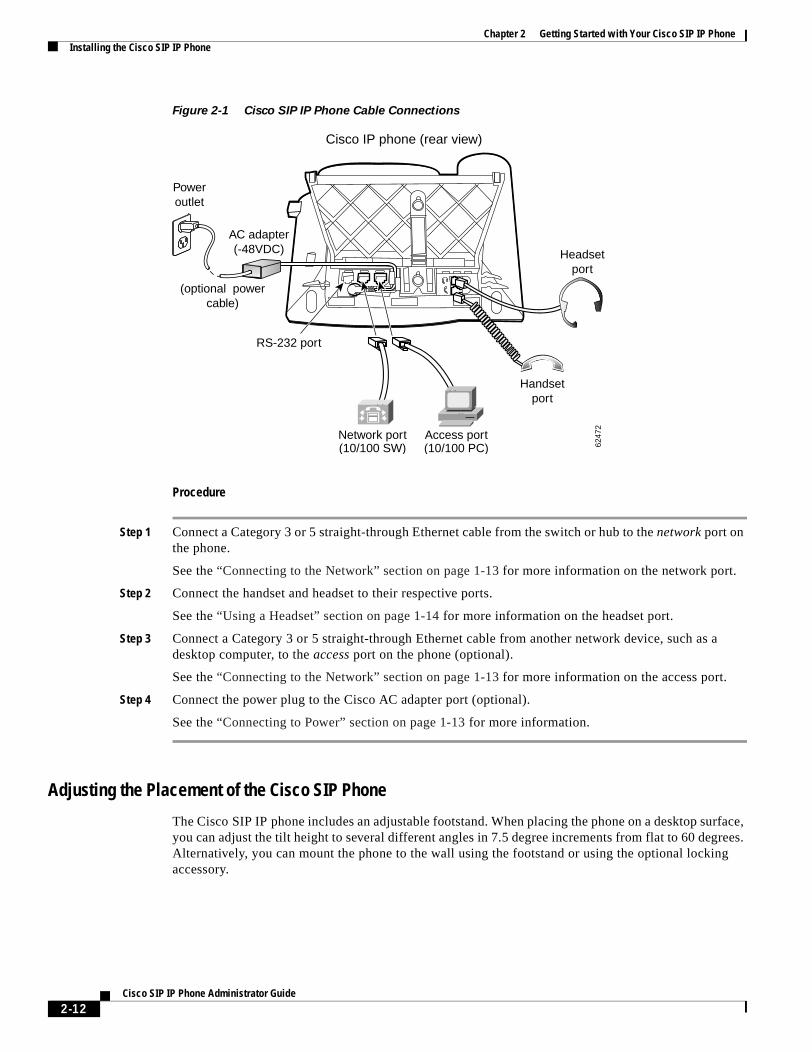
Chapter 2 Getting Started with Your Cisco SIP IP PhoneInstalling the Cisco SIP IP Phone
Figure 2-1 Cisco SIP IP Phone Cable Connections
Procedure
Step 1 Connect a Category 3 or 5 straight-through Ethernet cable from the switch or hub to the network port on the phone.
See the “Connecting to the Network” section on page 1-13 for more information on the network port.
Step 2 Connect the handset and headset to their respective ports.
See the “Using a Headset” section on page 1-14 for more information on the headset port.
Step 3 Connect a Category 3 or 5 straight-through Ethernet cable from another network device, such as a desktop computer, to the access port on the phone (optional).
See the “Connecting to the Network” section on page 1-13 for more information on the access port.
Step 4 Connect the power plug to the Cisco AC adapter port (optional).
See the “Connecting to Power” section on page 1-13 for more information.
Adjusting the Placement of the Cisco SIP Phone
The Cisco SIP IP phone includes an adjustable footstand. When placing the phone on a desktop surface, you can adjust the tilt height to several different angles in 7.5 degree increments from flat to 60 degrees. Alternatively, you can mount the phone to the wall using the footstand or using the optional locking accessory.
Handsetport
Headsetport
Cisco IP phone (rear view)
6247
2
Poweroutlet
RS-232 port
(optional powercable)
AC adapter(-48VDC)
Access port(10/100 PC)
Network port(10/100 SW)
2-12Cisco SIP IP Phone Administrator Guide
Chapter 2 Getting Started with Your Cisco SIP IP PhoneInstalling the Cisco SIP IP Phone
Adjusting the Phone Placement on the Desktop
Adjust the footstand to the height that provides optimum view of the display and use of the buttons and keys as shown in Figure 2-2.
To adjust the phone placement on the desktop:
Step 1 Push in the footstand adjustment knob.
Step 2 Adjust the footstand to its desired height and release the knob.
Mounting the Phone to the Wall
You can mount the Cisco SIP IP phone on the wall using the footstand as a mounting bracket or using the optional locking bracket. Use the following procedure to mount the phone on the wall using the standard footstand. To use the optional locking bracket, refer to the Installing the Wall Mount Kit for the Cisco IP Phone document.
Before You Begin
Mounting the Cisco SIP IP phone on the wall requires some tools and equipment that are not provided as standard equipment.
Following are the tools and parts required for a typical Cisco SIP IP phone installation:
• Screwdriver
• Screws to secure the Cisco SIP IP phone to the wall
Procedure
Step 1 Push in the footstand adjustment knob.
Step 2 Adjust the footstand so that it is flat against the back of the phone, as shown in Figure 2-2.
Step 3 Modify the handset rest so that the handset remains on the ear-piece rest when the phone is vertically placed.
a. Remove the handset from the ear-piece rest.
b. Locate the tab (handset wall hook) at the base of the ear-piece rest.
c. Slide this tab out, rotate it 180 degrees, and reinsert it.
d. Place the handset on the ear-piece rest.
Step 4 Insert two screws into a wall stud, matching them to the two screw holes on the back of the footstand.
The keyholes fit standard phone jack mounts.
Step 5 Hang the phone on the wall.
2-13Cisco SIP IP Phone Administrator Guide
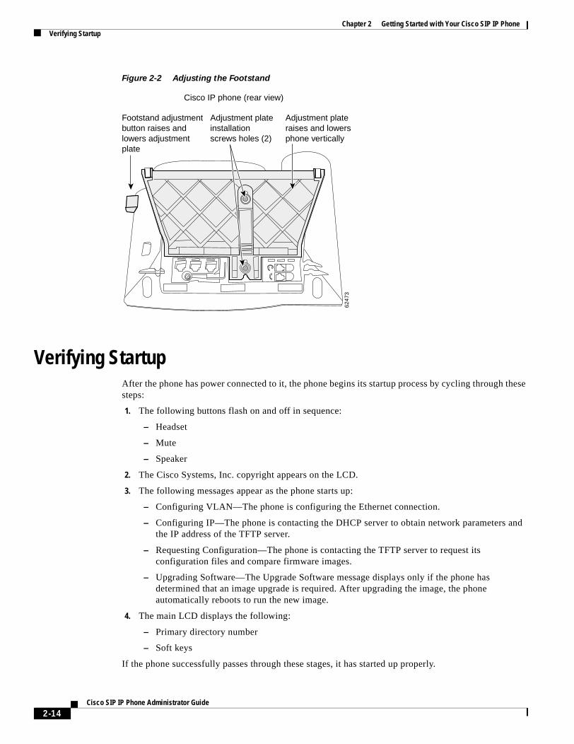
Chapter 2 Getting Started with Your Cisco SIP IP PhoneVerifying Startup
Figure 2-2 Adjusting the Footstand
Verifying StartupAfter the phone has power connected to it, the phone begins its startup process by cycling through these steps:
1. The following buttons flash on and off in sequence:
– Headset
– Mute
– Speaker
2. The Cisco Systems, Inc. copyright appears on the LCD.
3. The following messages appear as the phone starts up:
– Configuring VLAN—The phone is configuring the Ethernet connection.
– Configuring IP—The phone is contacting the DHCP server to obtain network parameters and the IP address of the TFTP server.
– Requesting Configuration—The phone is contacting the TFTP server to request its configuration files and compare firmware images.
– Upgrading Software—The Upgrade Software message displays only if the phone has determined that an image upgrade is required. After upgrading the image, the phone automatically reboots to run the new image.
4. The main LCD displays the following:
– Primary directory number
– Soft keys
If the phone successfully passes through these stages, it has started up properly.
Cisco IP phone (rear view)
Footstand adjustmentbutton raises and lowers adjustment plate
Adjustment plateraises and lowersphone vertically
Adjustment plateinstallationscrews holes (2)
6247
3
2-14Cisco SIP IP Phone Administrator Guide
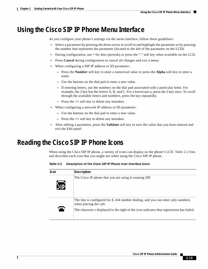
Chapter 2 Getting Started with Your Cisco SIP IP PhoneUsing the Cisco SIP IP Phone Menu Interface
Using the Cisco SIP IP Phone Menu InterfaceAs you configure your phone’s settings via the menu interface, follow these guidelines:
• Select a parameter by pressing the down arrow to scroll to and highlight the parameter or by pressing the number that represents the parameter (located to the left of the parameter on the LCD).
• During configuration, use * for dots (periods) or press the “.” soft key when available on the LCD.
• Press Cancel during configuration to cancel all changes and exit a menu.
• When configuring a SIP IP address or ID parameter:
– Press the Number soft key to enter a numerical value or press the Alpha soft key to enter a name.
– Use the buttons on the dial pad to enter a new value.
– If entering letters, use the numbers on the dial pad associated with a particular letter. For example, the 2 key has the letters A, B, and C. For a lowercase a, press the 2 key once. To scroll through the available letters and numbers, press the key repeatedly.
– Press the << soft key to delete any mistakes.
• When configuring a network IP address or ID parameter:
– Use the buttons on the dial pad to enter a new value.
– Press the << soft key to delete any mistakes.
• After editing a parameter, press the Validate soft key to save the value that you have entered and exit the Edit panel.
Reading the Cisco SIP IP Phone Icons When using the Cisco SIP IP phone, a variety of icons can display on the phone’s LCD. Table 2-2 lists and describes each icon that you might see while using the Cisco SIP IP phone.
Table 2-2 Description of the Cisco SIP IP Phone User Interface Icons
Icon Description
The Cisco IP phone that you are using is running SIP.
The line is configured for E.164 number dialing, and you can enter only numbers when placing the call.
The character x displayed to the right of the icon indicates that registration has failed.
2-15Cisco SIP IP Phone Administrator Guide
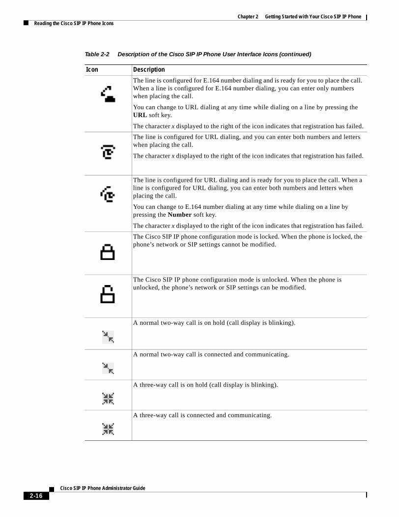
Chapter 2 Getting Started with Your Cisco SIP IP PhoneReading the Cisco SIP IP Phone Icons
The line is configured for E.164 number dialing and is ready for you to place the call. When a line is configured for E.164 number dialing, you can enter only numbers when placing the call.
You can change to URL dialing at any time while dialing on a line by pressing the URL soft key.
The character x displayed to the right of the icon indicates that registration has failed.
The line is configured for URL dialing, and you can enter both numbers and letters when placing the call.
The character x displayed to the right of the icon indicates that registration has failed.
The line is configured for URL dialing and is ready for you to place the call. When a line is configured for URL dialing, you can enter both numbers and letters when placing the call.
You can change to E.164 number dialing at any time while dialing on a line by pressing the Number soft key.
The character x displayed to the right of the icon indicates that registration has failed.
The Cisco SIP IP phone configuration mode is locked. When the phone is locked, the phone’s network or SIP settings cannot be modified.
The Cisco SIP IP phone configuration mode is unlocked. When the phone is unlocked, the phone’s network or SIP settings can be modified.
A normal two-way call is on hold (call display is blinking).
A normal two-way call is connected and communicating.
A three-way call is on hold (call display is blinking).
A three-way call is connected and communicating.
Table 2-2 Description of the Cisco SIP IP Phone User Interface Icons (continued)
Icon Description
2-16Cisco SIP IP Phone Administrator Guide
Chapter 2 Getting Started with Your Cisco SIP IP PhoneCustomizing the Cisco SIP IP Phone Ring Types
Customizing the Cisco SIP IP Phone Ring TypesThe Cisco SIP IP phone ships with two ring types: Chirp1 and Chirp2. By default, your ring type options will be those two choices. However, using the RINGLIST.DAT file, you can customize the ring types that are available to Cisco SIP IP phone users.
Step 1 Create a pulse code modulation (PCM) file of the desired ring types and store the PCM files in the root directory of your TFTP server. PCM files must contain no header information and must comply with the following format guidelines:
• 8000-Hz sampling rate
• 8 bits per sample
• u-law compression
Step 2 Using an ASCII editor, open the RINGLIST.DAT file, and for each of the ring types that you are adding, specify the name as you want it to appear on the Ring Type menu, press Tab, and then specify the filename of the ring type. For example, the format of a pointer in your RINGLIST.DAT file should appear similar to the following:
Ring Type 1ringer1.pcm
Step 3 After defining pointers for each of the ring types that you are adding, save your modifications and close the RINGLIST.DAT file.
Creating Dial PlansDial plans enable the Cisco SIP IP phone to support automatic dialing and automatic generation of a secondary dial tone. If a single dial plan is to be used for a system of phones, the dial plan is best specified in the default configuration file. However, you can create multiple dial plans and specify which phones are to use which dial plan by defining the dial_template parameter in the phone-specific configuration file. If one phone in a system of phones needs to use a different dial plan than the rest, you need to define the differing dial plan by specifying the dial_template parameter in that phone’s phone-specific configuration file.
Note We recommend that you define the dial_template parameter in the default configuration file for maintenance and control purposes. Specify the dial_template parameter in a phone-specific configuration file only if that phone needs to use a different dial plan than is being used by the other phones in the same system.
When creating a dial plan, remember the following:
• Dial plans must be in an .xml format and must be stored on your TFTP server.
• You must specify which dial plan a phone is to use by specifying the path to the dial plan in the dial_template parameter that you define in either the phone-specific configuration file or the default configuration. We recommend that the dial_template parameter be defined in the default configuration file unless a specific phone must use a dial plan that differs from the one being used by other phones in the same system.
2-17Cisco SIP IP Phone Administrator Guide
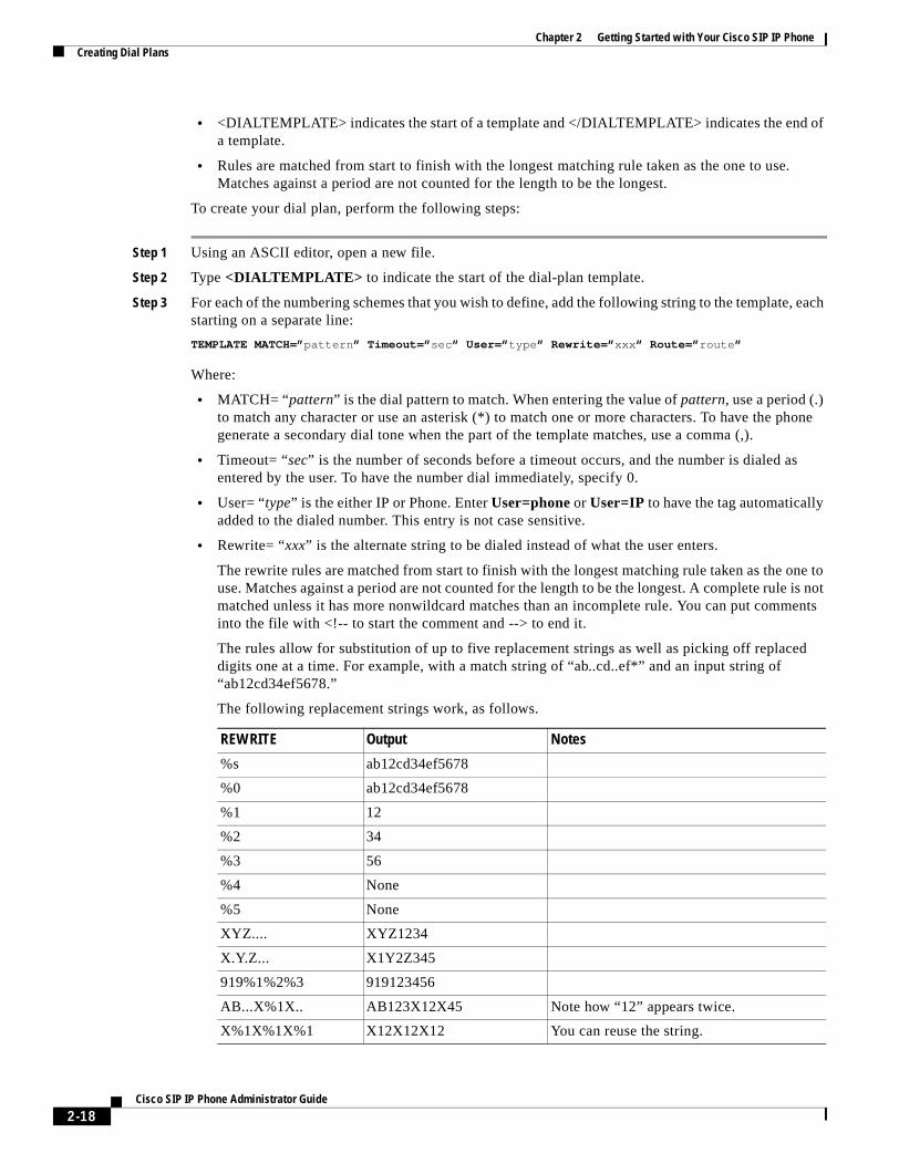
Chapter 2 Getting Started with Your Cisco SIP IP PhoneCreating Dial Plans
• <DIALTEMPLATE> indicates the start of a template and </DIALTEMPLATE> indicates the end of a template.
• Rules are matched from start to finish with the longest matching rule taken as the one to use. Matches against a period are not counted for the length to be the longest.
To create your dial plan, perform the following steps:
Step 1 Using an ASCII editor, open a new file.
Step 2 Type <DIALTEMPLATE> to indicate the start of the dial-plan template.
Step 3 For each of the numbering schemes that you wish to define, add the following string to the template, each starting on a separate line:
TEMPLATE MATCH=”pattern” Timeout=”sec” User=”type” Rewrite=”xxx” Route=”route”
Where:
• MATCH= “pattern” is the dial pattern to match. When entering the value of pattern, use a period (.) to match any character or use an asterisk (*) to match one or more characters. To have the phone generate a secondary dial tone when the part of the template matches, use a comma (,).
• Timeout= “sec” is the number of seconds before a timeout occurs, and the number is dialed as entered by the user. To have the number dial immediately, specify 0.
• User= “type” is the either IP or Phone. Enter User=phone or User=IP to have the tag automatically added to the dialed number. This entry is not case sensitive.
• Rewrite= “xxx” is the alternate string to be dialed instead of what the user enters.
The rewrite rules are matched from start to finish with the longest matching rule taken as the one to use. Matches against a period are not counted for the length to be the longest. A complete rule is not matched unless it has more nonwildcard matches than an incomplete rule. You can put comments into the file with <!-- to start the comment and --> to end it.
The rules allow for substitution of up to five replacement strings as well as picking off replaced digits one at a time. For example, with a match string of “ab..cd..ef*” and an input string of “ab12cd34ef5678.”
The following replacement strings work, as follows.
REWRITE Output Notes
%s ab12cd34ef5678
%0 ab12cd34ef5678
%1 12
%2 34
%3 56
%4 None
%5 None
XYZ.... XYZ1234
X.Y.Z... X1Y2Z345
919%1%2%3 919123456
AB...X%1X.. AB123X12X45 Note how “12” appears twice.
X%1X%1X%1 X12X12X12 You can reuse the string.
2-18Cisco SIP IP Phone Administrator Guide
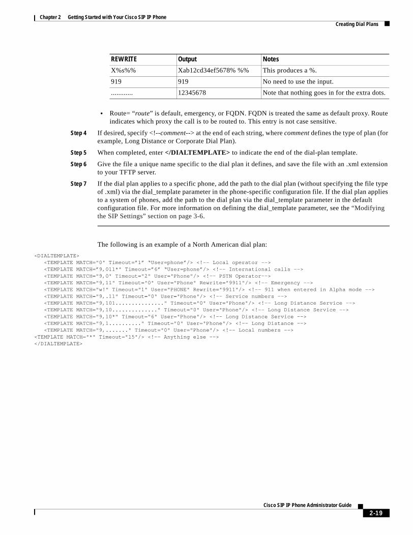
Chapter 2 Getting Started with Your Cisco SIP IP PhoneCreating Dial Plans
• Route= “route” is default, emergency, or FQDN. FQDN is treated the same as default proxy. Route indicates which proxy the call is to be routed to. This entry is not case sensitive.
Step 4 If desired, specify <!--comment--> at the end of each string, where comment defines the type of plan (for example, Long Distance or Corporate Dial Plan).
Step 5 When completed, enter </DIALTEMPLATE> to indicate the end of the dial-plan template.
Step 6 Give the file a unique name specific to the dial plan it defines, and save the file with an .xml extension to your TFTP server.
Step 7 If the dial plan applies to a specific phone, add the path to the dial plan (without specifying the file type of .xml) via the dial_template parameter in the phone-specific configuration file. If the dial plan applies to a system of phones, add the path to the dial plan via the dial_template parameter in the default configuration file. For more information on defining the dial_template parameter, see the “Modifying the SIP Settings” section on page 3-6.
The following is an example of a North American dial plan:
<DIALTEMPLATE> <TEMPLATE MATCH="0" Timeout=”1” “User=phone”/> <!-- Local operator --> <TEMPLATE MATCH=”9,011*" Timeout=”6” “User=phone”/> <!-- International calls --> <TEMPLATE MATCH="9,0" Timeout="2" User="Phone"/> <!-- PSTN Operator--> <TEMPLATE MATCH="9,11" Timeout="0" User="Phone" Rewrite="9911"/> <!-- Emergency --> <TEMPLATE MATCH="w!" Timeout="1" User="PHONE" Rewrite="9911"/> <!-- 911 when entered in Alpha mode --> <TEMPLATE MATCH="9,.11" Timeout="0" User="Phone"/> <!-- Service numbers --> <TEMPLATE MATCH="9,101..............." Timeout="0" User="Phone"/> <!-- Long Distance Service --> <TEMPLATE MATCH="9,10.............." Timeout="0" User="Phone"/> <!-- Long Distance Service --> <TEMPLATE MATCH="9,10*" Timeout="6" User="Phone"/> <!-- Long Distance Service --> <TEMPLATE MATCH="9,1.........." Timeout="0" User="Phone"/> <!-- Long Distance --> <TEMPLATE MATCH="9,......." Timeout="0" User="Phone"/> <!-- Local numbers --><TEMPLATE MATCH="*" Timeout="15"/> <!-- Anything else --></DIALTEMPLATE>
X%s%% Xab12cd34ef5678% %% This produces a %.
919 919 No need to use the input.
............ 12345678 Note that nothing goes in for the extra dots.
REWRITE Output Notes
2-19Cisco SIP IP Phone Administrator Guide

Chapter 2 Getting Started with Your Cisco SIP IP PhoneCreating Dial Plans
2-20Cisco SIP IP Phone Administrator Guide
C H A P T E R 3
Managing Cisco SIP IP PhonesThis chapter provides information on the following:
• Changing Your Configuration, page 3-1
• Modifying the Network Settings, page 3-2
• Modifying the SIP Settings, page 3-6
• Using the Command-Line Interface, page 3-29
• Setting the Date, Time, and Daylight Saving Time, page 3-35
• Erasing the Locally Defined Settings, page 3-41
• Accessing Status Information, page 3-42
• Upgrading the Cisco SIP IP Phone Firmware, page 3-44
• Performing an Image Upgrade and Remote Reboot, page 3-46
Changing Your ConfigurationYou can change your Cisco SIP IP phone configuration by any of the following methods:
• Using your phone buttons and soft keys. You must first follow the instructions in the “Entering Configuration Mode” section on page 3-2.
• Editing the default and phone-specific configuration files on the TFTP server. See the “Modifying SIP Parameters via a TFTP Server” section on page 3-9.
• Using Telnet or a console to connect to your Cisco SIP IP phone and using the command-line interface (CLI). You will need to the phone IP address. Press Settings, select Network Configuration, and scroll down to IP Address to find this address. The default Telnet password is “cisco.”
Note Use the CLI only to debug and troubleshoot your Cisco SIP IP phone.
You can change the following parameters:
• Network settings. See the “Modifying the Network Settings” section on page 3-2.
• SIP settings. See the “Modifying the SIP Settings” section on page 3-6.
3-1Cisco SIP IP Phone Administrator Guide
Chapter 3 Managing Cisco SIP IP PhonesModifying the Network Settings
• Call preferences settings. See the “Modifying the SIP Settings” section on page 3-6.
• XML URL settings. See the “Modifying the SIP Settings” section on page 3-6.
• Date, time, and daylight saving time settings. See the “Setting the Date, Time, and Daylight Saving Time” section on page 3-35.
Modifying the Network SettingsYou can display and configure the network settings of a Cisco SIP IP phone. The network settings include information such as the phone’s Dynamic Host Configuration Protocol (DHCP) server, MAC address, IP address, and domain name.
Entering Configuration ModeWhen you access the network configuration information on your Cisco SIP IP phone, you will notice that there is a padlock symbol located in the upper-right corner of your LCD. By default, the network configuration information is locked. Before you can modify any of the network configuration parameters, you must unlock the phone.
Unlocking Configuration ModeThere are two methods to unlock the configuration mode in Cisco SIP IP phones: one method for phones that have Release 4.2 or later and one method for phones that have Release 4.1 or earlier.
In Release 4.2 or Later
In Release 4.2 and later, an “Unlock Config” item displays in the phone settings menu. When the user selects Unlock Config, the user is prompted to enter a phone password using the alphanumeric entry function of the keypad. The phone password is set using the phone_password configuration parameter. When the correct password is entered, the configuration is unlocked and the settings can be changed.
When the Network Configuration or SIP Configuration menus display, the lock icon in the upper-right corner of your LCD will indicate an unlocked state. The unlocked symbol indicates that you can modify the network and SIP configuration settings.
When the Settings menu is exited, the phone will automatically relock the configuration.
In Release 4.1 or Earlier
To unlock the Cisco SIP IP phone for releases before Cisco Release 4.2, press **#.
Note Pressing **# activates the configuration mode for your phone; however there is no indication that an action has taken place.
If the Network Configuration or SIP Configuration panel is displayed, the lock icon in the upper-right corner of your LCD changes to an unlocked state. If you are located elsewhere in the Cisco SIP IP phone menus, the next time you access the Network Configuration or the SIP Configuration menus, the unlocked icon displays, and you can modify the network and SIP configuration settings.
3-2Cisco SIP IP Phone Administrator Guide

Chapter 3 Managing Cisco SIP IP PhonesModifying the Network Settings
Locking Configuration ModeThere are two methods to unlock the configuration mode in Cisco SIP IP phones: one method for phones that have Release 4.2 or later and one method for phones that have Release 4.1 or earlier.
In Release 4.2 or Later
When the configuration has been successfully unlocked, the menu item displayed is “Lock Config.” If you select this item, the configuration will relock. Also, if you exit the Settings menu the configuration will relock. Refer to the “Unlocking Configuration Mode” section on page 3-2 for more information.
When the Network Configuration or SIP Configuration menus display, the lock icon in the upper-right corner of your LCD will indicate a locked state. The lock symbol indicates that you cannot modify the network and SIP configuration settings.
In Release 4.1 or Earlier
To lock the Cisco SIP IP phone when you are done modifying the settings, press **#.
If the Network Configuration or SIP Configuration panel is displayed, the lock icon in the upper-right corner of your LCD changes to a locked state. If you are located elsewhere in the Cisco SIP IP phone menus, the next time you access the Network Configuration or the SIP Configuration panels, the lock icon will be displayed in a locked state.
The lock symbol indicates that you cannot modify the network and SIP configuration settings.
Changing the Network Settings
Before You Begin
When configuring network settings, remember the following:
• Unlock configuration mode as described in the “Unlocking Configuration Mode” section on page 3-2. By default, the network parameters are locked to ensure that end users cannot modify settings that might affect their network connectivity.
• Review the guidelines on using the Cisco SIP IP phone menus documented in the “Using the Cisco SIP IP Phone Menu Interface” section on page 2-15.
• After making your changes, relock configuration mode as described in the “Locking Configuration Mode” section on page 3-3.
To change the network settings, perform the following steps:
Step 1 Press the settings key. The Settings menu displays.
Step 2 Highlight Network Configuration.
Step 3 Press the Select soft key. The Network Configuration menu displays. Table 3-1 lists the network parameters available from the Network Configuration menu.
Step 4 When done, press the Save soft key. The phone programs the new information into Flash memory and resets.
3-3Cisco SIP IP Phone Administrator Guide

Chapter 3 Managing Cisco SIP IP PhonesModifying the Network Settings
Caution When you have completed your changes, ensure that you lock the phone as described in the “Locking Configuration Mode” section on page 3-3.
Table 3-1 Network Configuration Parameters
Parameter Can Edit? Description
Admin. VLAN Id Yes, but if you have an administrative VLAN assigned on the Catalyst switch, that setting overrides any changes made on the phone.
Unique identifier of the VLAN to which the phone is attached. The value in this field is used only in switched networks that are not Cisco networks.
Alternate TFTP Yes. Whether to use an alternate TFTP server. This field enables an administrator to specify the remote TFTP server rather than the local one. Possible values for this parameter are Yes and No. The default is No. When Yes is specified, the IP address in the TFTP Address parameter must be changed to the address of the alternate TFTP server.
Default Routers 1 through 5 Yes, but DHCP must be disabled.
IP address of the default gateway used by the phone. Default Routers 2 through 5 are the IP addresses of the gateways that the phone attempts to use as an alternate gateway if the primary gateway is unavailable.
DHCP Address Released Yes. Whether the IP address of the phone can be released for reuse in the network. When you set this field to Yes, the phone sends a DHCP release message to the DHCP server and goes into a release state. The release state provides enough time to remove the phone from the network before the phone attempts to acquire another IP address from the DHCP server. When moving the phone to a new network segment, you should first release the DHCP address.
DHCP Enabled Yes. Whether the phone will use DHCP to configure network settings (IP address, subnet mask, domain name, default router list, DNS server list, and TFTP address). Valid values for this field are Yes and No. By default, DHCP is enabled on the phone. To manually configure your IP settings, you must first disable DHCP.
DHCP Server No. IP address of the DHCP server from which the phone received its IP address and additional network settings.
DNS Servers 1 through 5 Yes, but DHCP must be disabled.
IP address of the DNS server used by the phone to resolve names to IP addresses. The phone attempts to use DNS servers 2 through 5 if DNS server 1 is unavailable.
Domain Name Yes. Name of the DNS domain in which the phone resides.
3-4Cisco SIP IP Phone Administrator Guide
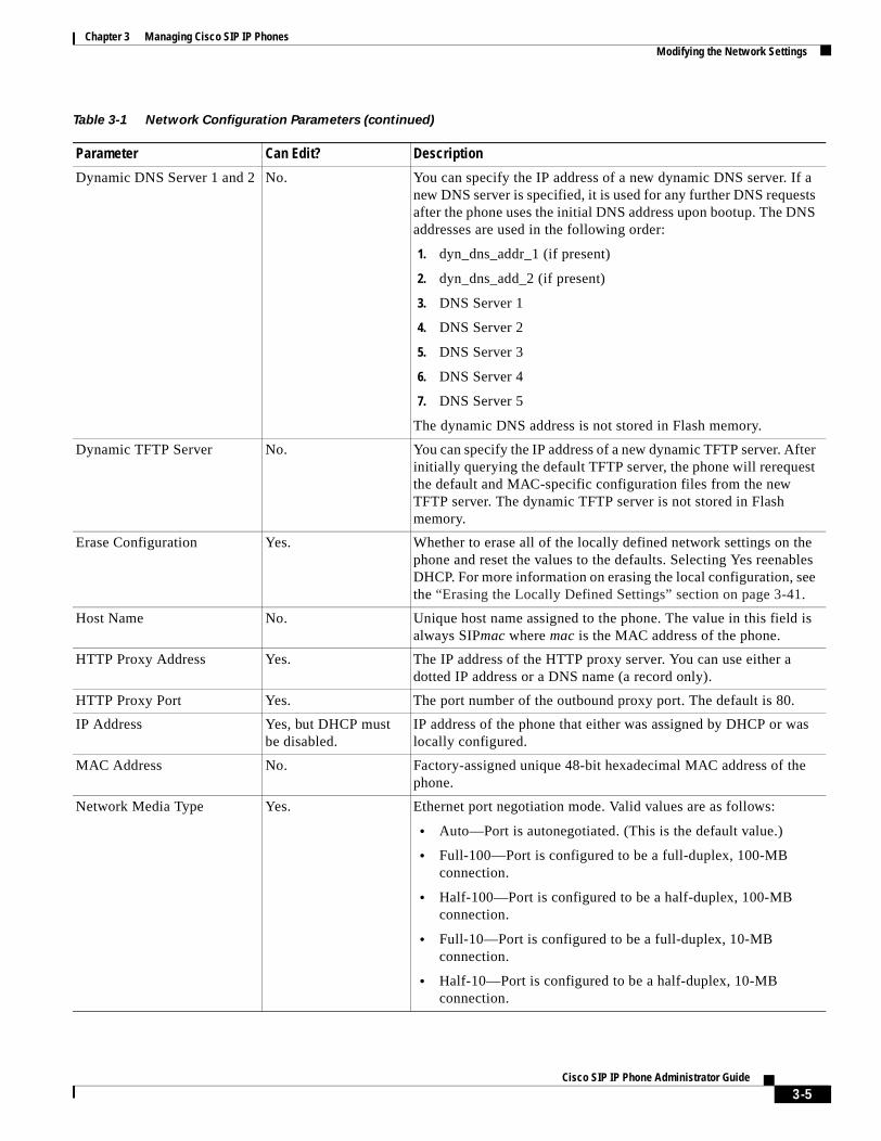
Chapter 3 Managing Cisco SIP IP PhonesModifying the Network Settings
Dynamic DNS Server 1 and 2 No. You can specify the IP address of a new dynamic DNS server. If a new DNS server is specified, it is used for any further DNS requests after the phone uses the initial DNS address upon bootup. The DNS addresses are used in the following order:
1. dyn_dns_addr_1 (if present)
2. dyn_dns_add_2 (if present)
3. DNS Server 1
4. DNS Server 2
5. DNS Server 3
6. DNS Server 4
7. DNS Server 5
The dynamic DNS address is not stored in Flash memory.
Dynamic TFTP Server No. You can specify the IP address of a new dynamic TFTP server. After initially querying the default TFTP server, the phone will rerequest the default and MAC-specific configuration files from the new TFTP server. The dynamic TFTP server is not stored in Flash memory.
Erase Configuration Yes. Whether to erase all of the locally defined network settings on the phone and reset the values to the defaults. Selecting Yes reenables DHCP. For more information on erasing the local configuration, see the “Erasing the Locally Defined Settings” section on page 3-41.
Host Name No. Unique host name assigned to the phone. The value in this field is always SIPmac where mac is the MAC address of the phone.
HTTP Proxy Address Yes. The IP address of the HTTP proxy server. You can use either a dotted IP address or a DNS name (a record only).
HTTP Proxy Port Yes. The port number of the outbound proxy port. The default is 80.
IP Address Yes, but DHCP must be disabled.
IP address of the phone that either was assigned by DHCP or was locally configured.
MAC Address No. Factory-assigned unique 48-bit hexadecimal MAC address of the phone.
Network Media Type Yes. Ethernet port negotiation mode. Valid values are as follows:
• Auto—Port is autonegotiated. (This is the default value.)
• Full-100—Port is configured to be a full-duplex, 100-MB connection.
• Half-100—Port is configured to be a half-duplex, 100-MB connection.
• Full-10—Port is configured to be a full-duplex, 10-MB connection.
• Half-10—Port is configured to be a half-duplex, 10-MB connection.
Table 3-1 Network Configuration Parameters (continued)
Parameter Can Edit? Description
3-5Cisco SIP IP Phone Administrator Guide
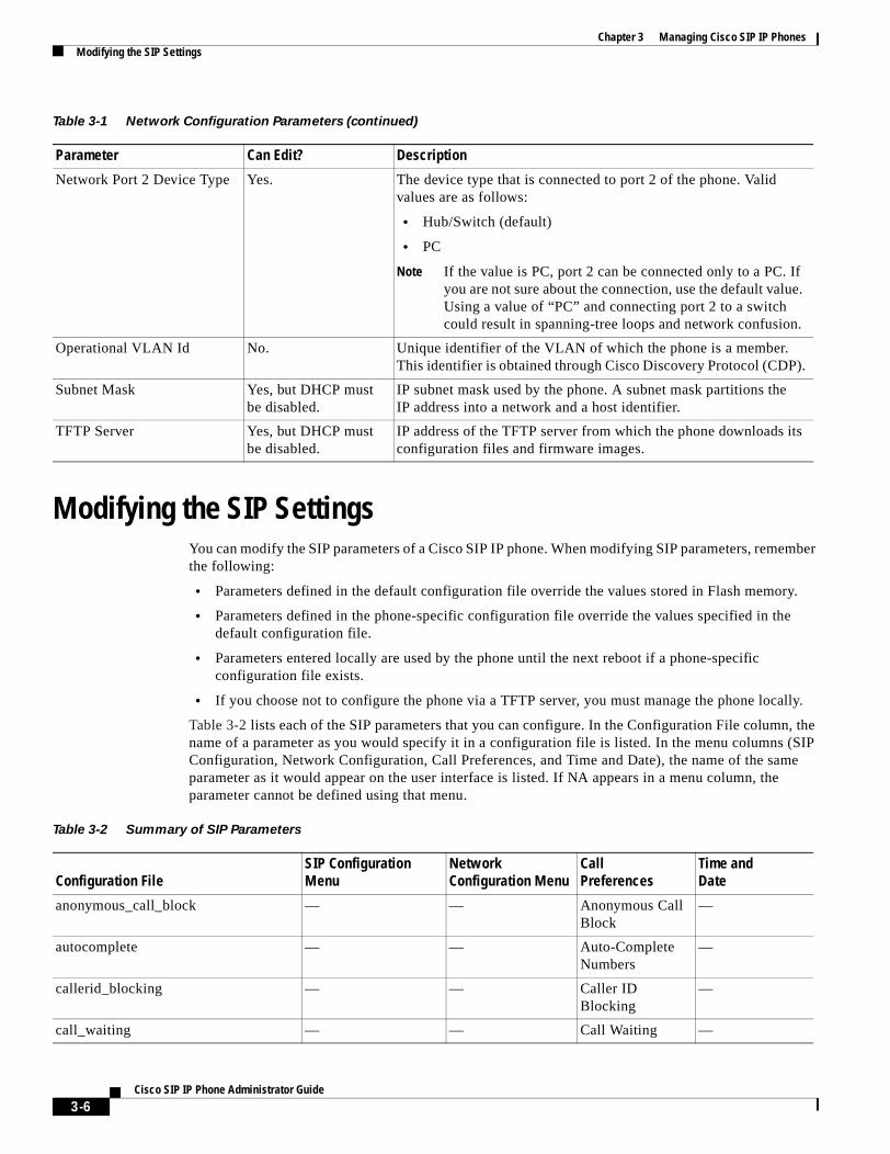
Chapter 3 Managing Cisco SIP IP PhonesModifying the SIP Settings
Modifying the SIP SettingsYou can modify the SIP parameters of a Cisco SIP IP phone. When modifying SIP parameters, remember the following:
• Parameters defined in the default configuration file override the values stored in Flash memory.
• Parameters defined in the phone-specific configuration file override the values specified in the default configuration file.
• Parameters entered locally are used by the phone until the next reboot if a phone-specific configuration file exists.
• If you choose not to configure the phone via a TFTP server, you must manage the phone locally.
Table 3-2 lists each of the SIP parameters that you can configure. In the Configuration File column, the name of a parameter as you would specify it in a configuration file is listed. In the menu columns (SIP Configuration, Network Configuration, Call Preferences, and Time and Date), the name of the same parameter as it would appear on the user interface is listed. If NA appears in a menu column, the parameter cannot be defined using that menu.
Network Port 2 Device Type Yes. The device type that is connected to port 2 of the phone. Valid values are as follows:
• Hub/Switch (default)
• PC
Note If the value is PC, port 2 can be connected only to a PC. If you are not sure about the connection, use the default value. Using a value of “PC” and connecting port 2 to a switch could result in spanning-tree loops and network confusion.
Operational VLAN Id No. Unique identifier of the VLAN of which the phone is a member. This identifier is obtained through Cisco Discovery Protocol (CDP).
Subnet Mask Yes, but DHCP must be disabled.
IP subnet mask used by the phone. A subnet mask partitions the IP address into a network and a host identifier.
TFTP Server Yes, but DHCP must be disabled.
IP address of the TFTP server from which the phone downloads its configuration files and firmware images.
Table 3-1 Network Configuration Parameters (continued)
Parameter Can Edit? Description
Table 3-2 Summary of SIP Parameters
Configuration FileSIP Configuration Menu
Network Configuration Menu
CallPreferences
Time andDate
anonymous_call_block — — Anonymous Call Block
—
autocomplete — — Auto-Complete Numbers
—
callerid_blocking — — Caller ID Blocking
—
call_waiting — — Call Waiting —
3-6Cisco SIP IP Phone Administrator Guide
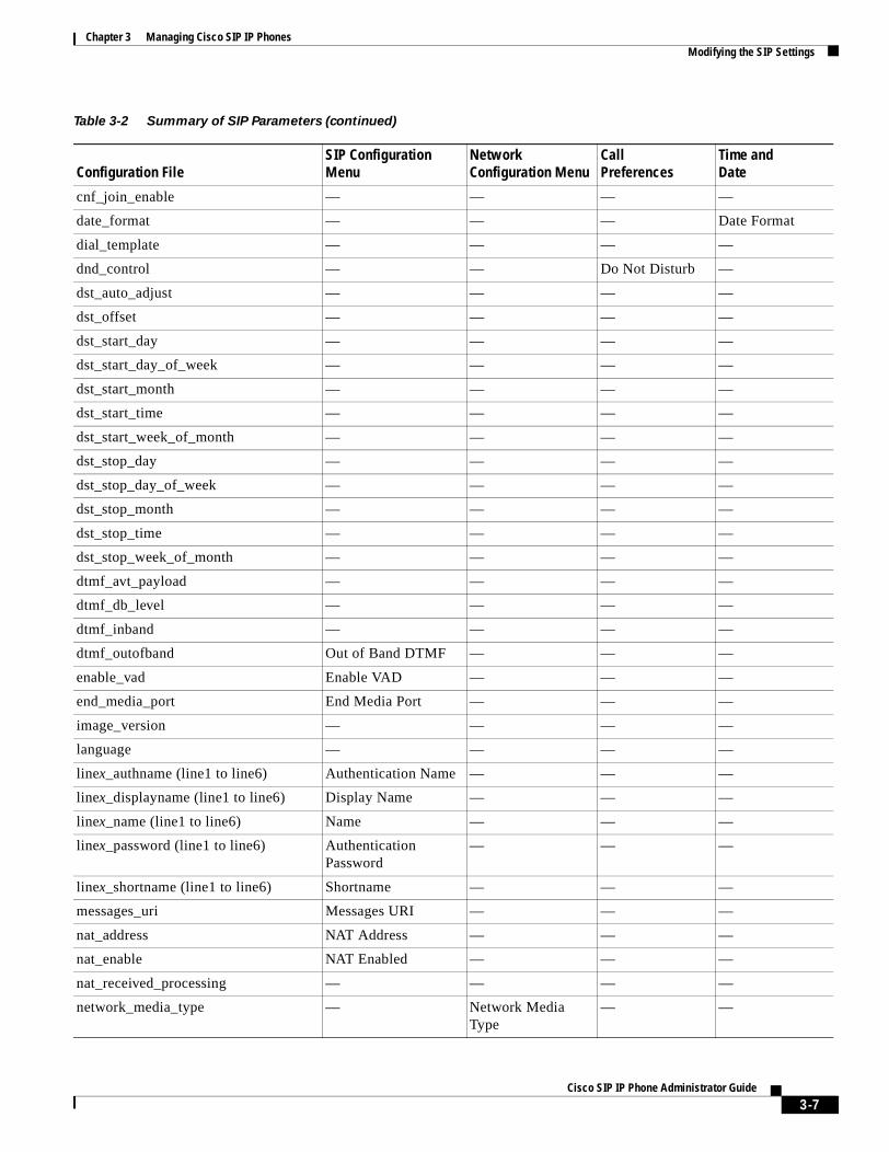
Chapter 3 Managing Cisco SIP IP PhonesModifying the SIP Settings
cnf_join_enable — — — —
date_format — — — Date Format
dial_template — — — —
dnd_control — — Do Not Disturb —
dst_auto_adjust — — — —
dst_offset — — — —
dst_start_day — — — —
dst_start_day_of_week — — — —
dst_start_month — — — —
dst_start_time — — — —
dst_start_week_of_month — — — —
dst_stop_day — — — —
dst_stop_day_of_week — — — —
dst_stop_month — — — —
dst_stop_time — — — —
dst_stop_week_of_month — — — —
dtmf_avt_payload — — — —
dtmf_db_level — — — —
dtmf_inband — — — —
dtmf_outofband Out of Band DTMF — — —
enable_vad Enable VAD — — —
end_media_port End Media Port — — —
image_version — — — —
language — — — —
linex_authname (line1 to line6) Authentication Name — — —
linex_displayname (line1 to line6) Display Name — — —
linex_name (line1 to line6) Name — — —
linex_password (line1 to line6) Authentication Password
— — —
linex_shortname (line1 to line6) Shortname — — —
messages_uri Messages URI — — —
nat_address NAT Address — — —
nat_enable NAT Enabled — — —
nat_received_processing — — — —
network_media_type — Network Media Type
— —
Table 3-2 Summary of SIP Parameters (continued)
Configuration FileSIP Configuration Menu
Network Configuration Menu
CallPreferences
Time andDate
3-7Cisco SIP IP Phone Administrator Guide
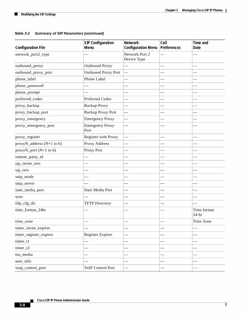
Chapter 3 Managing Cisco SIP IP PhonesModifying the SIP Settings
network_port2_type — Network Port 2 Device Type
— —
outbound_proxy Outbound Proxy — — —
outbound_proxy_port Outbound Proxy Port — — —
phone_label Phone Label — — —
phone_password — — — —
phone_prompt — — — —
preferred_codec Preferred Codec — — —
proxy_backup Backup Proxy — — —
proxy_backup_port Backup Proxy Port — — —
proxy_emergency Emergency Proxy — — —
proxy_emergency_port Emergency Proxy Port
— — —
proxy_register Register with Proxy — — —
proxyN_address (N=1 to 6) Proxy Address — — —
proxyN_port (N=1 to 6) Proxy Port — — —
remote_party_id — — — —
sip_invite_retx — — — —
sip_retx — — — —
sntp_mode — — — —
sntp_server — — — —
start_media_port Start Media Port — — —
sync — — — —
tftp_cfg_dir TFTP Directory — — —
time_format_24hr — — — Time format 24-hr
time_zone — — — Time Zone
timer_invite_expires — — — —
timer_register_expires Register Expires — — —
timer_t1 — — — —
timer_t2 — — — —
tos_media — — — —
user_info — — — —
voip_control_port VoIP Control Port — — —
Table 3-2 Summary of SIP Parameters (continued)
Configuration FileSIP Configuration Menu
Network Configuration Menu
CallPreferences
Time andDate
3-8Cisco SIP IP Phone Administrator Guide
Chapter 3 Managing Cisco SIP IP PhonesModifying the SIP Settings
Modifying SIP Parameters via a TFTP ServerIf you have set up your phones to retrieve their SIP parameters via a TFTP server as described in the “Modifying SIP Parameters via a TFTP Server” section on page 3-9, you can also modify your SIP parameters using the configuration files.
As explained in the “Configuring SIP Parameters” section on page 2-4, there are two configuration files that you can use to define the SIP parameters: the default configuration file and the phone-specific configuration file. If used, the default configuration file must be stored in the root directory of your TFTP server. The phone-specific configuration file can be stored in the root directory of the TFTP server or in a subdirectory in which phone-specific configuration files are stored.
While it is not required, Cisco recommends that you use the default configuration file to define values for SIP parameters that are common to all phones. Doing so will make controlling and maintaining your network easier. You can then define only those parameters that are specific to a phone in the phone-specific configuration file. Phone-specific parameters should be defined only in a phone-specific configuration file, or they should be manually configured. Phone-specific parameters should not be defined in the default configuration file.
Modifying the Default SIP Configuration File
In the default configuration file (SIPDefault.cnf), Cisco recommends that you maintain the SIP parameters that are common to all your phones. By maintaining these parameters in the default configuration file, you can perform global changes, such as upgrading the image version, without having to modify the phone-specific configuration file for each phone.
Before You Begin
• Ensure that you have downloaded the SIPDefault.cnf file from Cisco.com to the root directory of your TFTP server.
• Review the guidelines documented in the “Configuring SIP Parameters” section on page 2-4.
Note Refer to the “Setting the Date, Time, and Daylight Saving Time” section on page 3-35 for more information.
Step 1 Using an ASCII editor, open the SIPDefault.cnf file and define or modify values for the SIP parameters shown in Table 3-3, as necessary.
Step 2 Save the file with the same filename, SIPDefault.cnf, to the root directory of your TFTP server.
3-9Cisco SIP IP Phone Administrator Guide
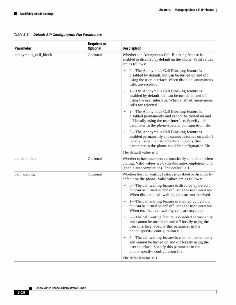
Chapter 3 Managing Cisco SIP IP PhonesModifying the SIP Settings
Table 3-3 Default SIP Configuration File Parameters
ParameterRequired or Optional Description
anonymous_call_block Optional Whether the Anonymous Call Blocking feature is enabled or disabled by default on the phone. Valid values are as follows:
• 0—The Anonymous Call Blocking feature is disabled by default, but can be turned on and off using the user interface. When disabled, anonymous calls are received.
• 1—The Anonymous Call Blocking feature is enabled by default, but can be turned on and off using the user interface. When enabled, anonymous calls are rejected
• 2—The Anonymous Call Blocking feature is disabled permanently and cannot be turned on and off locally using the user interface. Specify this parameter in the phone-specific configuration file.
• 3—The Anonymous Call Blocking feature is enabled permanently and cannot be turned on and off locally using the user interface. Specify this parameter in the phone-specific configuration file.
The default value is 0.
autocomplete Optional Whether to have numbers automatically completed when dialing. Valid values are 0 (disable autocompletion) or 1 (enable autocompletion). The default is 1.
call_waiting Optional Whether the call waiting feature is enabled or disabled by default on the phone. Valid values are as follows:
• 0—The call waiting feature is disabled by default, but can be turned on and off using the user interface. When disabled, call waiting calls are not received.
• 1—The call waiting feature is enabled by default, but can be turned on and off using the user interface. When enabled, call waiting calls are accepted.
• 2—The call waiting feature is disabled permanently and cannot be turned on and off locally using the user interface. Specify this parameter in the phone-specific configuration file.
• 3—The call waiting feature is enabled permanently and cannot be turned on and off locally using the user interface. Specify this parameter in the phone-specific configuration file.
The default value is 1.
3-10Cisco SIP IP Phone Administrator Guide
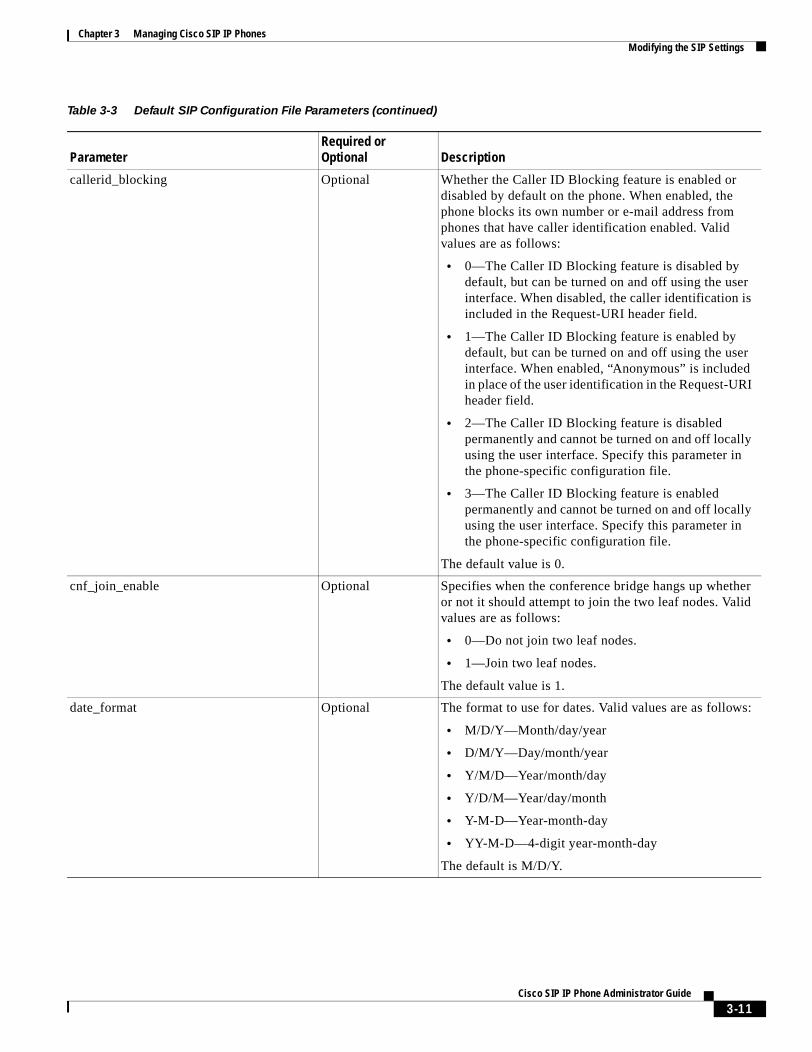
Chapter 3 Managing Cisco SIP IP PhonesModifying the SIP Settings
callerid_blocking Optional Whether the Caller ID Blocking feature is enabled or disabled by default on the phone. When enabled, the phone blocks its own number or e-mail address from phones that have caller identification enabled. Valid values are as follows:
• 0—The Caller ID Blocking feature is disabled by default, but can be turned on and off using the user interface. When disabled, the caller identification is included in the Request-URI header field.
• 1—The Caller ID Blocking feature is enabled by default, but can be turned on and off using the user interface. When enabled, “Anonymous” is included in place of the user identification in the Request-URI header field.
• 2—The Caller ID Blocking feature is disabled permanently and cannot be turned on and off locally using the user interface. Specify this parameter in the phone-specific configuration file.
• 3—The Caller ID Blocking feature is enabled permanently and cannot be turned on and off locally using the user interface. Specify this parameter in the phone-specific configuration file.
The default value is 0.
cnf_join_enable Optional Specifies when the conference bridge hangs up whether or not it should attempt to join the two leaf nodes. Valid values are as follows:
• 0—Do not join two leaf nodes.
• 1—Join two leaf nodes.
The default value is 1.
date_format Optional The format to use for dates. Valid values are as follows:
• M/D/Y—Month/day/year
• D/M/Y—Day/month/year
• Y/M/D—Year/month/day
• Y/D/M—Year/day/month
• Y-M-D—Year-month-day
• YY-M-D—4-digit year-month-day
The default is M/D/Y.
Table 3-3 Default SIP Configuration File Parameters (continued)
ParameterRequired or Optional Description
3-11Cisco SIP IP Phone Administrator Guide
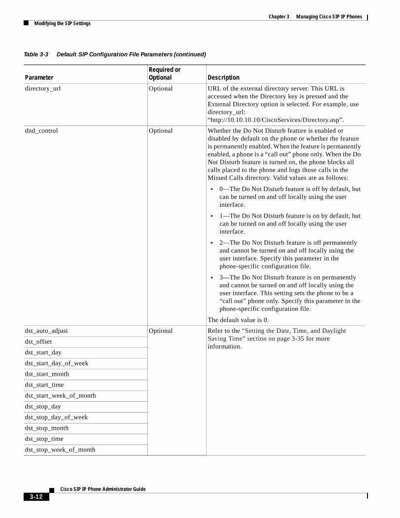
Chapter 3 Managing Cisco SIP IP PhonesModifying the SIP Settings
directory_url Optional URL of the external directory server. This URL is accessed when the Directory key is pressed and the External Directory option is selected. For example, use directory_url: “http://10.10.10.10/CiscoServices/Directory.asp”.
dnd_control Optional Whether the Do Not Disturb feature is enabled or disabled by default on the phone or whether the feature is permanently enabled. When the feature is permanently enabled, a phone is a “call out” phone only. When the Do Not Disturb feature is turned on, the phone blocks all calls placed to the phone and logs those calls in the Missed Calls directory. Valid values are as follows:
• 0—The Do Not Disturb feature is off by default, but can be turned on and off locally using the user interface.
• 1—The Do Not Disturb feature is on by default, but can be turned on and off locally using the user interface.
• 2—The Do Not Disturb feature is off permanently and cannot be turned on and off locally using the user interface. Specify this parameter in the phone-specific configuration file.
• 3—The Do Not Disturb feature is on permanently and cannot be turned on and off locally using the user interface. This setting sets the phone to be a “call out” phone only. Specify this parameter in the phone-specific configuration file.
The default value is 0.
dst_auto_adjust Optional Refer to the “Setting the Date, Time, and Daylight Saving Time” section on page 3-35 for more information.
dst_offset
dst_start_day
dst_start_day_of_week
dst_start_month
dst_start_time
dst_start_week_of_month
dst_stop_day
dst_stop_day_of_week
dst_stop_month
dst_stop_time
dst_stop_week_of_month
Table 3-3 Default SIP Configuration File Parameters (continued)
ParameterRequired or Optional Description
3-12Cisco SIP IP Phone Administrator Guide
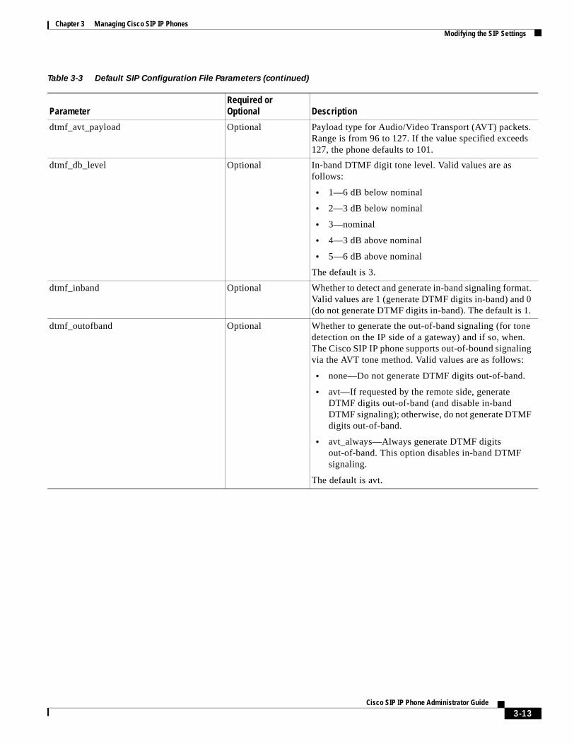
Chapter 3 Managing Cisco SIP IP PhonesModifying the SIP Settings
dtmf_avt_payload Optional Payload type for Audio/Video Transport (AVT) packets. Range is from 96 to 127. If the value specified exceeds 127, the phone defaults to 101.
dtmf_db_level Optional In-band DTMF digit tone level. Valid values are as follows:
• 1—6 dB below nominal
• 2—3 dB below nominal
• 3—nominal
• 4—3 dB above nominal
• 5—6 dB above nominal
The default is 3.
dtmf_inband Optional Whether to detect and generate in-band signaling format. Valid values are 1 (generate DTMF digits in-band) and 0 (do not generate DTMF digits in-band). The default is 1.
dtmf_outofband Optional Whether to generate the out-of-band signaling (for tone detection on the IP side of a gateway) and if so, when. The Cisco SIP IP phone supports out-of-bound signaling via the AVT tone method. Valid values are as follows:
• none—Do not generate DTMF digits out-of-band.
• avt—If requested by the remote side, generate DTMF digits out-of-band (and disable in-band DTMF signaling); otherwise, do not generate DTMF digits out-of-band.
• avt_always—Always generate DTMF digits out-of-band. This option disables in-band DTMF signaling.
The default is avt.
Table 3-3 Default SIP Configuration File Parameters (continued)
ParameterRequired or Optional Description
3-13Cisco SIP IP Phone Administrator Guide
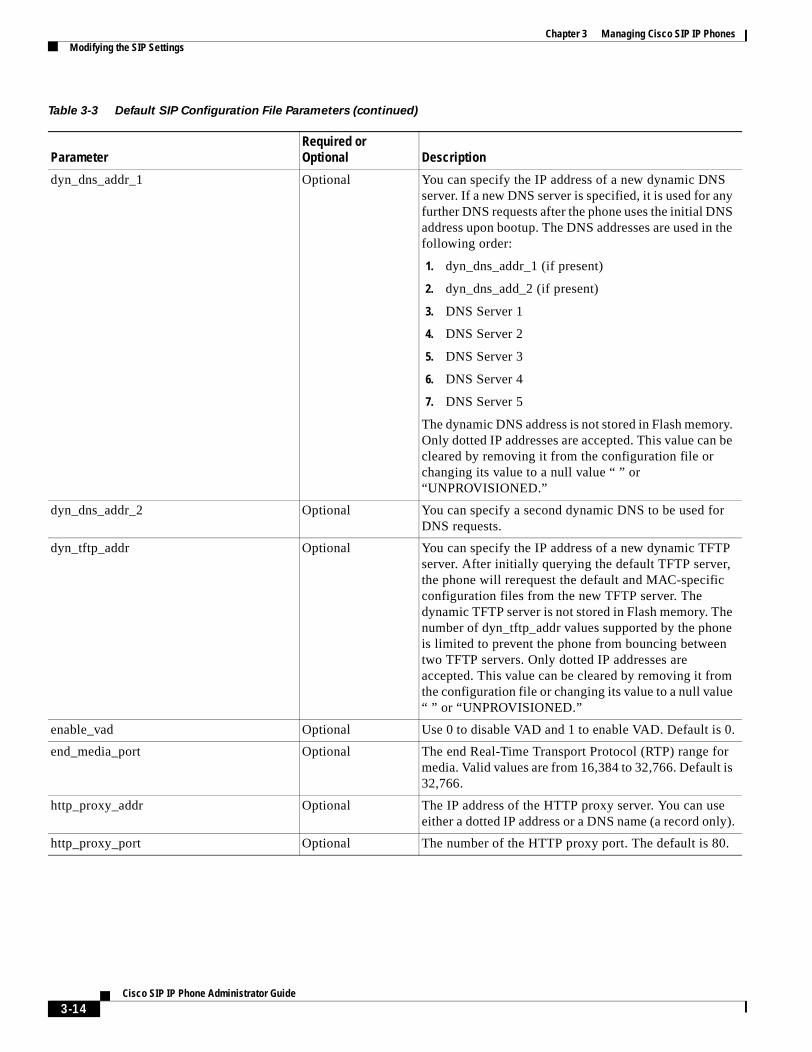
Chapter 3 Managing Cisco SIP IP PhonesModifying the SIP Settings
dyn_dns_addr_1 Optional You can specify the IP address of a new dynamic DNS server. If a new DNS server is specified, it is used for any further DNS requests after the phone uses the initial DNS address upon bootup. The DNS addresses are used in the following order:
1. dyn_dns_addr_1 (if present)
2. dyn_dns_add_2 (if present)
3. DNS Server 1
4. DNS Server 2
5. DNS Server 3
6. DNS Server 4
7. DNS Server 5
The dynamic DNS address is not stored in Flash memory. Only dotted IP addresses are accepted. This value can be cleared by removing it from the configuration file or changing its value to a null value “ ” or “UNPROVISIONED.”
dyn_dns_addr_2 Optional You can specify a second dynamic DNS to be used for DNS requests.
dyn_tftp_addr Optional You can specify the IP address of a new dynamic TFTP server. After initially querying the default TFTP server, the phone will rerequest the default and MAC-specific configuration files from the new TFTP server. The dynamic TFTP server is not stored in Flash memory. The number of dyn_tftp_addr values supported by the phone is limited to prevent the phone from bouncing between two TFTP servers. Only dotted IP addresses are accepted. This value can be cleared by removing it from the configuration file or changing its value to a null value “ ” or “UNPROVISIONED.”
enable_vad Optional Use 0 to disable VAD and 1 to enable VAD. Default is 0.
end_media_port Optional The end Real-Time Transport Protocol (RTP) range for media. Valid values are from 16,384 to 32,766. Default is 32,766.
http_proxy_addr Optional The IP address of the HTTP proxy server. You can use either a dotted IP address or a DNS name (a record only).
http_proxy_port Optional The number of the HTTP proxy port. The default is 80.
Table 3-3 Default SIP Configuration File Parameters (continued)
ParameterRequired or Optional Description
3-14Cisco SIP IP Phone Administrator Guide
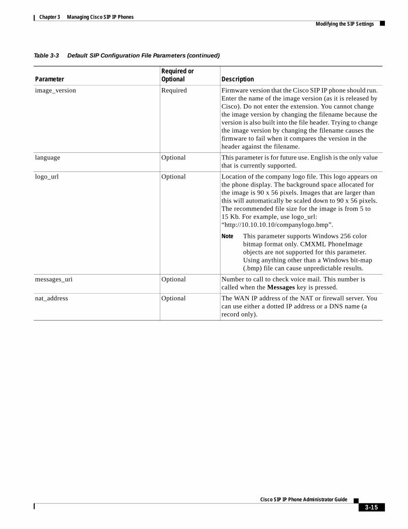
Chapter 3 Managing Cisco SIP IP PhonesModifying the SIP Settings
image_version Required Firmware version that the Cisco SIP IP phone should run. Enter the name of the image version (as it is released by Cisco). Do not enter the extension. You cannot change the image version by changing the filename because the version is also built into the file header. Trying to change the image version by changing the filename causes the firmware to fail when it compares the version in the header against the filename.
language Optional This parameter is for future use. English is the only value that is currently supported.
logo_url Optional Location of the company logo file. This logo appears on the phone display. The background space allocated for the image is 90 x 56 pixels. Images that are larger than this will automatically be scaled down to 90 x 56 pixels. The recommended file size for the image is from 5 to 15 Kb. For example, use logo_url: “http://10.10.10.10/companylogo.bmp”.
Note This parameter supports Windows 256 color bitmap format only. CMXML PhoneImage objects are not supported for this parameter. Using anything other than a Windows bit-map (.bmp) file can cause unpredictable results.
messages_uri Optional Number to call to check voice mail. This number is called when the Messages key is pressed.
nat_address Optional The WAN IP address of the NAT or firewall server. You can use either a dotted IP address or a DNS name (a record only).
Table 3-3 Default SIP Configuration File Parameters (continued)
ParameterRequired or Optional Description
3-15Cisco SIP IP Phone Administrator Guide
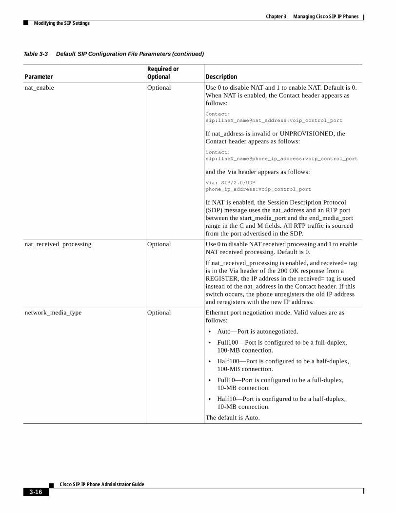
Chapter 3 Managing Cisco SIP IP PhonesModifying the SIP Settings
nat_enable Optional Use 0 to disable NAT and 1 to enable NAT. Default is 0. When NAT is enabled, the Contact header appears as follows:
Contact: sip:lineN_name@nat_address:voip_control_port
If nat_address is invalid or UNPROVISIONED, the Contact header appears as follows:
Contact: sip:lineN_name@phone_ip_address:voip_control_port
and the Via header appears as follows:
Via: SIP/2.0/UDP phone_ip_address:voip_control_port
If NAT is enabled, the Session Description Protocol (SDP) message uses the nat_address and an RTP port between the start_media_port and the end_media_port range in the C and M fields. All RTP traffic is sourced from the port advertised in the SDP.
nat_received_processing Optional Use 0 to disable NAT received processing and 1 to enable NAT received processing. Default is 0.
If nat_received_processing is enabled, and received= tag is in the Via header of the 200 OK response from a REGISTER, the IP address in the received= tag is used instead of the nat_address in the Contact header. If this switch occurs, the phone unregisters the old IP address and reregisters with the new IP address.
network_media_type Optional Ethernet port negotiation mode. Valid values are as follows:
• Auto—Port is autonegotiated.
• Full100—Port is configured to be a full-duplex, 100-MB connection.
• Half100—Port is configured to be a half-duplex, 100-MB connection.
• Full10—Port is configured to be a full-duplex, 10-MB connection.
• Half10—Port is configured to be a half-duplex, 10-MB connection.
The default is Auto.
Table 3-3 Default SIP Configuration File Parameters (continued)
ParameterRequired or Optional Description
3-16Cisco SIP IP Phone Administrator Guide
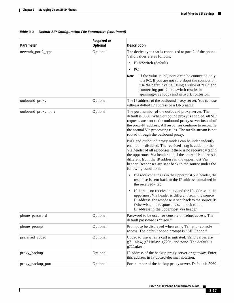
Chapter 3 Managing Cisco SIP IP PhonesModifying the SIP Settings
network_port2_type Optional The device type that is connected to port 2 of the phone. Valid values are as follows:
• Hub/Switch (default)
• PC
Note If the value is PC, port 2 can be connected only to a PC. If you are not sure about the connection, use the default value. Using a value of “PC” and connecting port 2 to a switch results in spanning-tree loops and network confusion.
outbound_proxy Optional The IP address of the outbound proxy server. You can use either a dotted IP address or a DNS name.
outbound_proxy_port Optional The port number of the outbound proxy server. The default is 5060. When outbound proxy is enabled, all SIP requests are sent to the outbound proxy server instead of the proxyN_address. All responses continue to reconcile the normal Via processing rules. The media stream is not routed through the outbound proxy.
NAT and outbound proxy modes can be independently enabled or disabled. The received= tag is added to the Via header of all responses if there is no received= tag in the uppermost Via header and if the source IP address is different from the IP address in the uppermost Via header. Responses are sent back to the source under the following conditions:
• If a received= tag is in the uppermost Via header, the response is sent back to the IP address contained in the received= tag.
• If there is no received= tag and the IP address in the uppermost Via header is different from the source IP address, the response is sent back to the source IP. Otherwise, the response is sent back to the IP address in the uppermost Via header.
phone_password Optional Password to be used for console or Telnet access. The default password is “cisco.”
phone_prompt Optional Prompt to be displayed when using Telnet or console access. The default phone prompt is “SIP Phone.”
preferred_codec Optional Codec to use when a call is initiated. Valid values are g711alaw, g711ulaw, g729a, and none. The default is g711ulaw.
proxy_backup Optional IP address of the backup proxy server or gateway. Enter this address in IP dotted-decimal notation.
proxy_backup_port Optional Port number of the backup proxy server. Default is 5060.
Table 3-3 Default SIP Configuration File Parameters (continued)
ParameterRequired or Optional Description
3-17Cisco SIP IP Phone Administrator Guide
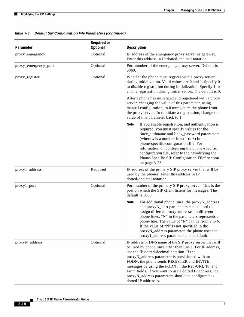
Chapter 3 Managing Cisco SIP IP PhonesModifying the SIP Settings
proxy_emergency Optional IP address of the emergency proxy server or gateway. Enter this address in IP dotted-decimal notation.
proxy_emergency_port Optional Port number of the emergency proxy server. Default is 5060.
proxy_register Optional Whether the phone must register with a proxy server during initialization. Valid values are 0 and 1. Specify 0 to disable registration during initialization. Specify 1 to enable registration during initialization. The default is 0.
After a phone has initialized and registered with a proxy server, changing the value of this parameter, using manual configuration, to 0 unregisters the phone from the proxy server. To reinitiate a registration, change the value of this parameter back to 1.
Note If you enable registration, and authentication is required, you must specify values for the linex_authname and linex_password parameters (where x is a number from 1 to 6) in the phone-specific configuration file. For information on configuring the phone-specific configuration file, refer to the “Modifying the Phone-Specific SIP Configuration File” section on page 3-23.
proxy1_address Required IP address of the primary SIP proxy server that will be used by the phones. Enter this address in IP dotted-decimal notation.
proxy1_port Optional Port number of the primary SIP proxy server. This is the port on which the SIP client listens for messages. The default is 5060.
Note For additional phone lines, the proxyN_address and proxyN_port parameters can be used to assign different proxy addresses to different phone lines. “N” in the parameters represents a phone line. The value of “N” can be from 2 to 6. If the value of “N” is not specified in the proxyN_address parameter, the phone uses the proxy1_address parameter as the default.
proxyN_address Optional IP address or DNS name of the SIP proxy server that will be used by phone lines other than line 1. For IP address, use the IP dotted-decimal notation. If the proxyN_address parameter is provisioned with an FQDN, the phone sends REGISTER and INVITE messages by using the FQDN in the Req-URI, To, and From fields. If you want to use a dotted IP address, the proxyN_address parameters should be configured as dotted IP addresses.
Table 3-3 Default SIP Configuration File Parameters (continued)
ParameterRequired or Optional Description
3-18Cisco SIP IP Phone Administrator Guide
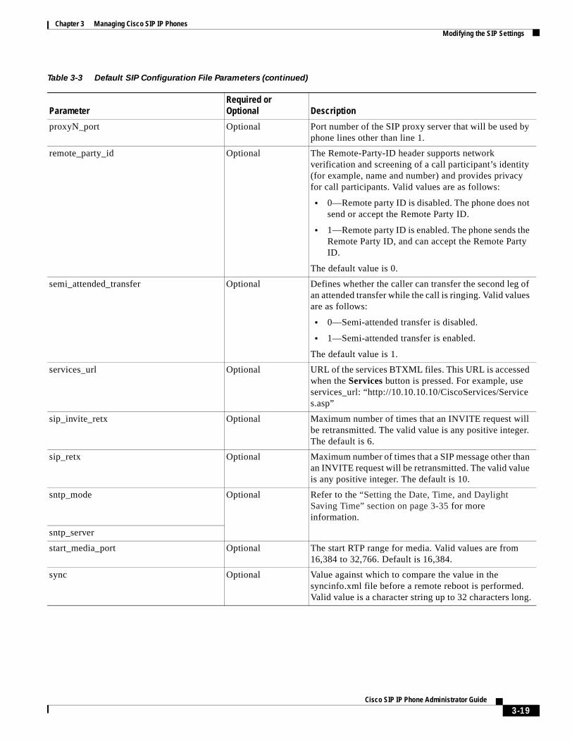
Chapter 3 Managing Cisco SIP IP PhonesModifying the SIP Settings
proxyN_port Optional Port number of the SIP proxy server that will be used by phone lines other than line 1.
remote_party_id Optional The Remote-Party-ID header supports network verification and screening of a call participant’s identity (for example, name and number) and provides privacy for call participants. Valid values are as follows:
• 0—Remote party ID is disabled. The phone does not send or accept the Remote Party ID.
• 1—Remote party ID is enabled. The phone sends the Remote Party ID, and can accept the Remote Party ID.
The default value is 0.
semi_attended_transfer Optional Defines whether the caller can transfer the second leg of an attended transfer while the call is ringing. Valid values are as follows:
• 0—Semi-attended transfer is disabled.
• 1—Semi-attended transfer is enabled.
The default value is 1.
services_url Optional URL of the services BTXML files. This URL is accessed when the Services button is pressed. For example, use services_url: “http://10.10.10.10/CiscoServices/Services.asp”
sip_invite_retx Optional Maximum number of times that an INVITE request will be retransmitted. The valid value is any positive integer. The default is 6.
sip_retx Optional Maximum number of times that a SIP message other than an INVITE request will be retransmitted. The valid value is any positive integer. The default is 10.
sntp_mode Optional Refer to the “Setting the Date, Time, and Daylight Saving Time” section on page 3-35 for more information.
sntp_server
start_media_port Optional The start RTP range for media. Valid values are from 16,384 to 32,766. Default is 16,384.
sync Optional Value against which to compare the value in the syncinfo.xml file before a remote reboot is performed. Valid value is a character string up to 32 characters long.
Table 3-3 Default SIP Configuration File Parameters (continued)
ParameterRequired or Optional Description
3-19Cisco SIP IP Phone Administrator Guide
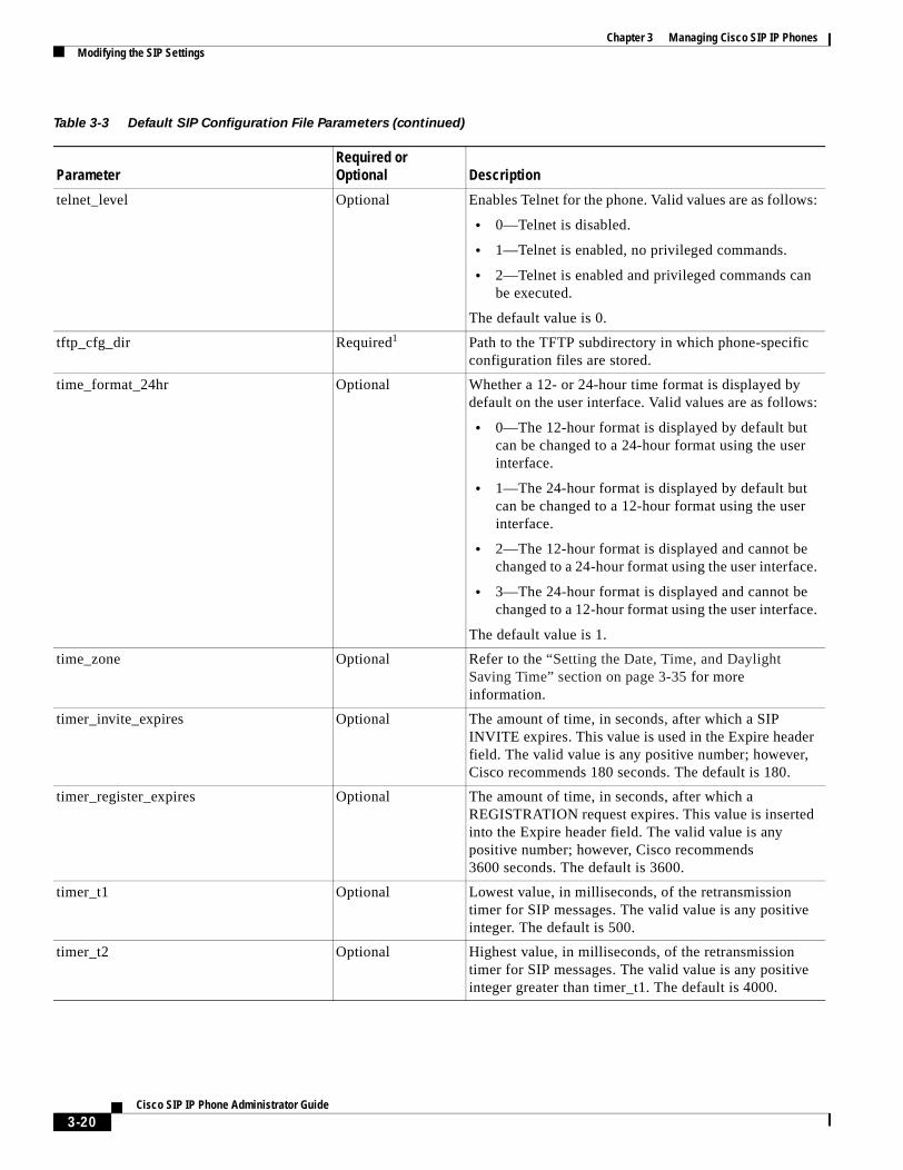
Chapter 3 Managing Cisco SIP IP PhonesModifying the SIP Settings
telnet_level Optional Enables Telnet for the phone. Valid values are as follows:
• 0—Telnet is disabled.
• 1—Telnet is enabled, no privileged commands.
• 2—Telnet is enabled and privileged commands can be executed.
The default value is 0.
tftp_cfg_dir Required1 Path to the TFTP subdirectory in which phone-specific configuration files are stored.
time_format_24hr Optional Whether a 12- or 24-hour time format is displayed by default on the user interface. Valid values are as follows:
• 0—The 12-hour format is displayed by default but can be changed to a 24-hour format using the user interface.
• 1—The 24-hour format is displayed by default but can be changed to a 12-hour format using the user interface.
• 2—The 12-hour format is displayed and cannot be changed to a 24-hour format using the user interface.
• 3—The 24-hour format is displayed and cannot be changed to a 12-hour format using the user interface.
The default value is 1.
time_zone Optional Refer to the “Setting the Date, Time, and Daylight Saving Time” section on page 3-35 for more information.
timer_invite_expires Optional The amount of time, in seconds, after which a SIP INVITE expires. This value is used in the Expire header field. The valid value is any positive number; however, Cisco recommends 180 seconds. The default is 180.
timer_register_expires Optional The amount of time, in seconds, after which a REGISTRATION request expires. This value is inserted into the Expire header field. The valid value is any positive number; however, Cisco recommends 3600 seconds. The default is 3600.
timer_t1 Optional Lowest value, in milliseconds, of the retransmission timer for SIP messages. The valid value is any positive integer. The default is 500.
timer_t2 Optional Highest value, in milliseconds, of the retransmission timer for SIP messages. The valid value is any positive integer greater than timer_t1. The default is 4000.
Table 3-3 Default SIP Configuration File Parameters (continued)
ParameterRequired or Optional Description
3-20Cisco SIP IP Phone Administrator Guide
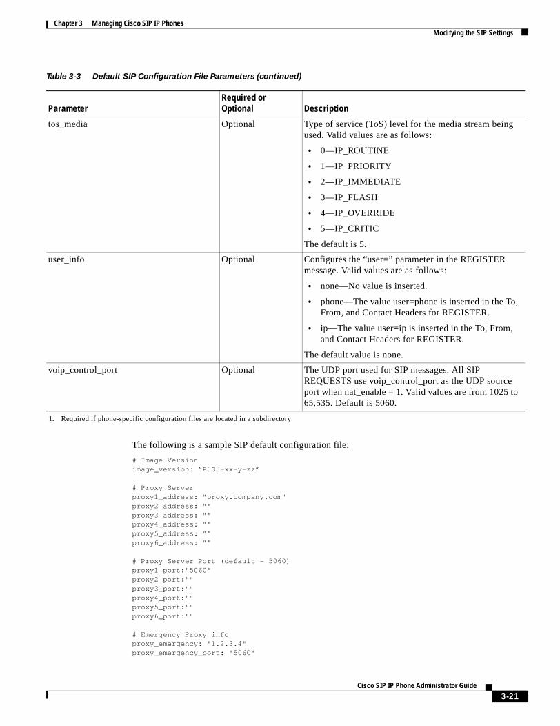
Chapter 3 Managing Cisco SIP IP PhonesModifying the SIP Settings
The following is a sample SIP default configuration file:
# Image Versionimage_version: “P0S3-xx-y-zz” # Proxy Serverproxy1_address: "proxy.company.com"proxy2_address: ""proxy3_address: "" proxy4_address: ""proxy5_address: ""proxy6_address: "" # Proxy Server Port (default - 5060)proxy1_port:"5060"proxy2_port:""proxy3_port:""proxy4_port:""proxy5_port:""proxy6_port:""
# Emergency Proxy infoproxy_emergency: "1.2.3.4"proxy_emergency_port: "5060"
tos_media Optional Type of service (ToS) level for the media stream being used. Valid values are as follows:
• 0—IP_ROUTINE
• 1—IP_PRIORITY
• 2—IP_IMMEDIATE
• 3—IP_FLASH
• 4—IP_OVERRIDE
• 5—IP_CRITIC
The default is 5.
user_info Optional Configures the “user=” parameter in the REGISTER message. Valid values are as follows:
• none—No value is inserted.
• phone—The value user=phone is inserted in the To, From, and Contact Headers for REGISTER.
• ip—The value user=ip is inserted in the To, From, and Contact Headers for REGISTER.
The default value is none.
voip_control_port Optional The UDP port used for SIP messages. All SIP REQUESTS use voip_control_port as the UDP source port when nat_enable = 1. Valid values are from 1025 to 65,535. Default is 5060.
1. Required if phone-specific configuration files are located in a subdirectory.
Table 3-3 Default SIP Configuration File Parameters (continued)
ParameterRequired or Optional Description
3-21Cisco SIP IP Phone Administrator Guide
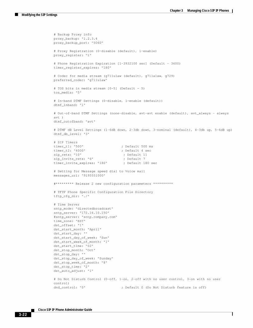
Chapter 3 Managing Cisco SIP IP PhonesModifying the SIP Settings
# Backup Proxy infoproxy_backup: "1.2.3.4proxy_backup_port: "5060" # Proxy Registration (0-disable (default), 1-enable)proxy_register: "1" # Phone Registration Expiration [1-3932100 sec] (Default - 3600)timer_register_expires: "180" # Codec for media stream (g711ulaw (default), g711alaw, g729)preferred_codec: "g711ulaw" # TOS bits in media stream [0-5] (Default - 5)tos_media: "5" # In-band DTMF Settings (0-disable, 1-enable (default))dtmf_inband: "1" # Out-of-band DTMF Settings (none-disable, avt-avt enable (default), avt_always - always avt )dtmf_outofband: "avt" # DTMF dB Level Settings (1-6dB down, 2-3db down, 3-nominal (default), 4-3db up, 5-6dB up)dtmf_db_level: "3" # SIP Timerstimer_t1: "500" ; Default 500 mstimer_t2: "4000" ; Default 4 secsip_retx: "10" ; Default 11sip_invite_retx: "6" ; Default 7timer_invite_expires: "180" ; Default 180 sec # Setting for Message speed dial to Voice mailmessages_uri: "9195551000"
#********* Release 2 new configuration parameters ********** # TFTP Phone Specific Configuration File Directorytftp_cfg_dir: "./" # Time Serversntp_mode: "directedbroadcast"sntp_server: "172.16.10.150"#sntp_server: "sntp.company.com"time_zone: "EST"dst_offset: "1"dst_start_month: "April"dst_start_day: ""dst_start_day_of_week: "Sun"dst_start_week_of_month: "1"dst_start_time: "02"dst_stop_month: "Oct"dst_stop_day: ""dst_stop_day_of_week: "Sunday"dst_stop_week_of_month: "8"dst_stop_time: "2"dst_auto_adjust: "1" # Do Not Disturb Control (0-off, 1-on, 2-off with no user control, 3-on with no user control)dnd_control: "0" ; Default 0 (Do Not Disturb feature is off)
3-22Cisco SIP IP Phone Administrator Guide
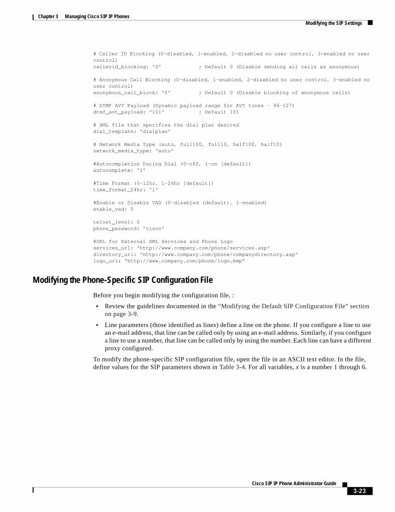
Chapter 3 Managing Cisco SIP IP PhonesModifying the SIP Settings
# Caller ID Blocking (0-disabled, 1-enabled, 2-disabled no user control, 3-enabled no user control)callerid_blocking: "0" ; Default 0 (Disable sending all calls as anonymous) # Anonymous Call Blocking (0-disabled, 1-enabled, 2-disabled no user control, 3-enabled no user control)anonymous_call_block: "0" ; Default 0 (Disable blocking of anonymous calls) # DTMF AVT Payload (Dynamic payload range for AVT tones - 96-127)dtmf_avt_payload: "101" ; Default 101 # XML file that specifies the dial plan desireddial_template: "dialplan"
# Network Media Type (auto, full100, full10, half100, half10)network_media_type: "auto"
#Autocompletion During Dial (0-off, 1-on [default])autocomplete: "1"
#Time Format (0-12hr, 1-24hr [default])time_format_24hr: "1"
#Enable or Disable VAD (0-disabled (default), 1-enabled)enable_vad: 0
telnet_level: 0phone_password: "cisco"
#URL for External XML Services and Phone Logoservices_url: "http://www.company.com/phone/services.asp"directory_url: "http://www.company.com/phone/companydirectory.asp"logo_url: “http://www.company.com/phone/logo.bmp”
Modifying the Phone-Specific SIP Configuration File
Before you begin modifying the configuration file, :
• Review the guidelines documented in the “Modifying the Default SIP Configuration File” section on page 3-9.
• Line parameters (those identified as linex) define a line on the phone. If you configure a line to use an e-mail address, that line can be called only by using an e-mail address. Similarly, if you configure a line to use a number, that line can be called only by using the number. Each line can have a different proxy configured.
To modify the phone-specific SIP configuration file, open the file in an ASCII text editor. In the file, define values for the SIP parameters shown in Table 3-4. For all variables, x is a number 1 through 6.
3-23Cisco SIP IP Phone Administrator Guide
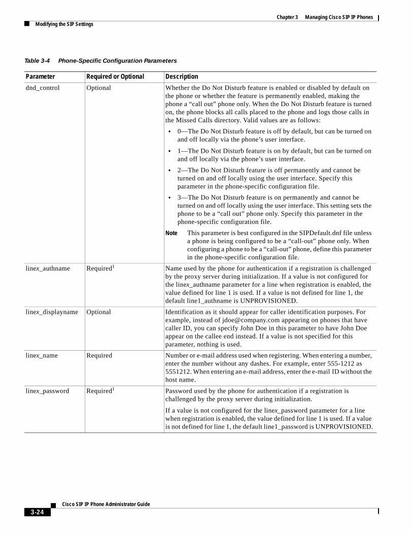
Chapter 3 Managing Cisco SIP IP PhonesModifying the SIP Settings
Table 3-4 Phone-Specific Configuration Parameters
Parameter Required or Optional Description
dnd_control Optional Whether the Do Not Disturb feature is enabled or disabled by default on the phone or whether the feature is permanently enabled, making the phone a “call out” phone only. When the Do Not Disturb feature is turned on, the phone blocks all calls placed to the phone and logs those calls in the Missed Calls directory. Valid values are as follows:
• 0—The Do Not Disturb feature is off by default, but can be turned on and off locally via the phone’s user interface.
• 1—The Do Not Disturb feature is on by default, but can be turned on and off locally via the phone’s user interface.
• 2—The Do Not Disturb feature is off permanently and cannot be turned on and off locally using the user interface. Specify this parameter in the phone-specific configuration file.
• 3—The Do Not Disturb feature is on permanently and cannot be turned on and off locally using the user interface. This setting sets the phone to be a “call out” phone only. Specify this parameter in the phone-specific configuration file.
Note This parameter is best configured in the SIPDefault.dnf file unless a phone is being configured to be a “call-out” phone only. When configuring a phone to be a “call-out” phone, define this parameter in the phone-specific configuration file.
linex_authname Required1 Name used by the phone for authentication if a registration is challenged by the proxy server during initialization. If a value is not configured for the linex_authname parameter for a line when registration is enabled, the value defined for line 1 is used. If a value is not defined for line 1, the default line1_authname is UNPROVISIONED.
linex_displayname Optional Identification as it should appear for caller identification purposes. For example, instead of [email protected] appearing on phones that have caller ID, you can specify John Doe in this parameter to have John Doe appear on the callee end instead. If a value is not specified for this parameter, nothing is used.
linex_name Required Number or e-mail address used when registering. When entering a number, enter the number without any dashes. For example, enter 555-1212 as 5551212. When entering an e-mail address, enter the e-mail ID without the host name.
linex_password Required1 Password used by the phone for authentication if a registration is challenged by the proxy server during initialization.
If a value is not configured for the linex_password parameter for a line when registration is enabled, the value defined for line 1 is used. If a value is not defined for line 1, the default line1_password is UNPROVISIONED.
3-24Cisco SIP IP Phone Administrator Guide
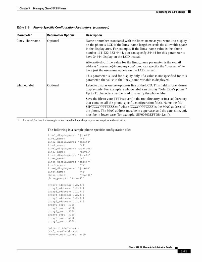
Chapter 3 Managing Cisco SIP IP PhonesModifying the SIP Settings
The following is a sample phone-specific configuration file:
line1_displayname: "jdoe43"line1_name: "43"line2_displayname: "jdoe44"line2_name: "44"line3_displayname: "pgatour"line3_name: "duval"line4_displayname: "jdoe46"line4_name: "46"line5_displayname: "jdoe47"line5_name: "47"line6_displayname: "jdoe48"line6_name: "48"phone_label: "jdoe4X"phone_prompt: "John-43"
proxy1_address: 1.2.3.4proxy2_address: 1.2.3.4proxy3_address: 1.2.3.4proxy4_address: 1.2.3.4proxy5_address: 1.2.3.4proxy6_address: 1.2.3.4proxy1_port: 5060 proxy2_port: 5060 proxy3_port: 5060proxy4_port: 5060proxy5_port: 5060proxy6_port: 5060
callerid_blocking: 0dtmf_outofband: avtnetwork_media_type: auto
linex_shortname Optional Name or number associated with the linex_name as you want it to display on the phone’s LCD if the linex_name length exceeds the allowable space in the display area. For example, if the linex_name value is the phone number 111-222-333-4444, you can specify 34444 for this parameter to have 34444 display on the LCD instead.
Alternatively, if the value for the linex_name parameter is the e-mail address “[email protected]”, you can specify the “username” to have just the username appear on the LCD instead.
This parameter is used for display only. If a value is not specified for this parameter, the value in the linex_name variable is displayed.
phone_label Optional Label to display on the top status line of the LCD. This field is for end-user display only. For example, a phone label can display “John Doe’s phone.” Up to 11 characters can be used to specify the phone label.
Save the file to your TFTP server (in the root directory or in a subdirectory that contains all the phone-specific configuration files). Name the file SIPXXXXYYYYZZZZ.cnf where XXXXYYYYZZZZ is the MAC address of the phone. The MAC address must be in uppercase, and the extension, cnf, must be in lower case (for example, SIP00503EFFD842.cnf).
1. Required for line 1 when registration is enabled and the proxy server requires authentication.
Table 3-4 Phone-Specific Configuration Parameters (continued)
Parameter Required or Optional Description
3-25Cisco SIP IP Phone Administrator Guide
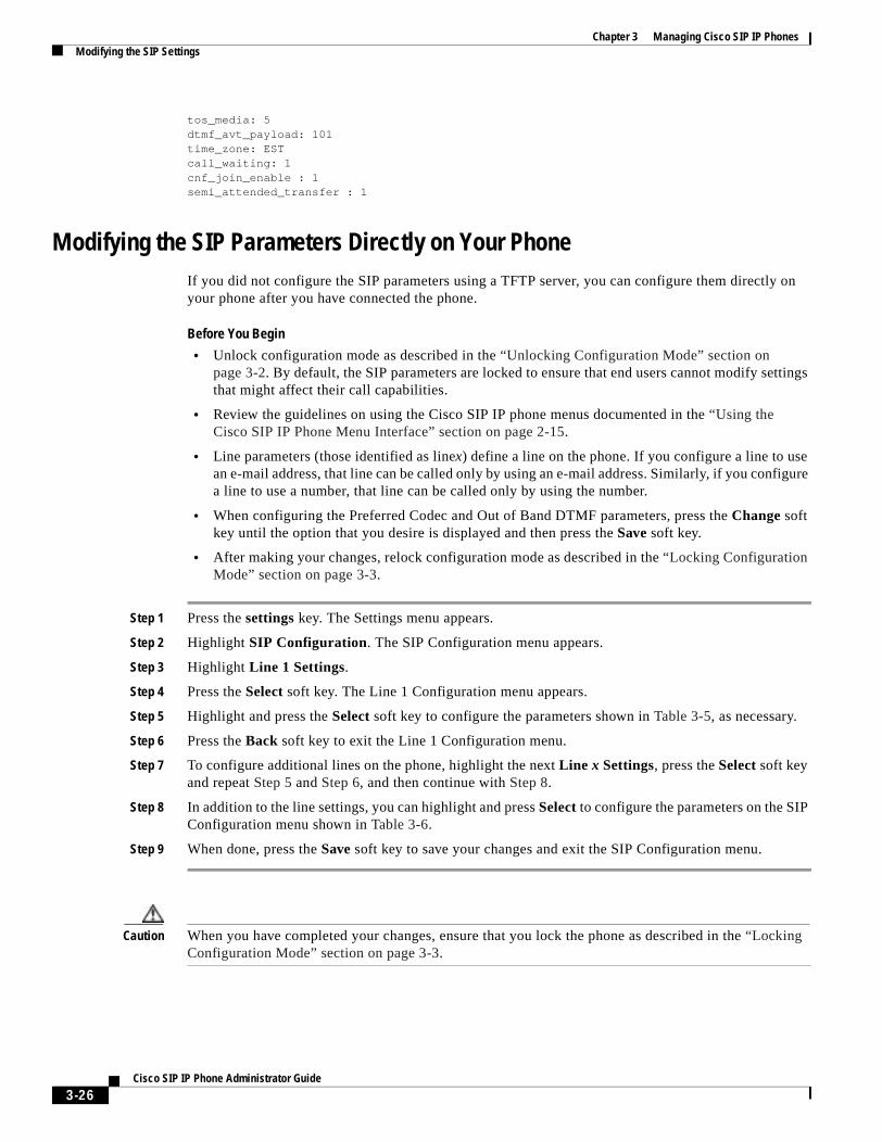
Chapter 3 Managing Cisco SIP IP PhonesModifying the SIP Settings
tos_media: 5dtmf_avt_payload: 101time_zone: ESTcall_waiting: 1cnf_join_enable : 1semi_attended_transfer : 1
Modifying the SIP Parameters Directly on Your PhoneIf you did not configure the SIP parameters using a TFTP server, you can configure them directly on your phone after you have connected the phone.
Before You Begin
• Unlock configuration mode as described in the “Unlocking Configuration Mode” section on page 3-2. By default, the SIP parameters are locked to ensure that end users cannot modify settings that might affect their call capabilities.
• Review the guidelines on using the Cisco SIP IP phone menus documented in the “Using the Cisco SIP IP Phone Menu Interface” section on page 2-15.
• Line parameters (those identified as linex) define a line on the phone. If you configure a line to use an e-mail address, that line can be called only by using an e-mail address. Similarly, if you configure a line to use a number, that line can be called only by using the number.
• When configuring the Preferred Codec and Out of Band DTMF parameters, press the Change soft key until the option that you desire is displayed and then press the Save soft key.
• After making your changes, relock configuration mode as described in the “Locking Configuration Mode” section on page 3-3.
Step 1 Press the settings key. The Settings menu appears.
Step 2 Highlight SIP Configuration. The SIP Configuration menu appears.
Step 3 Highlight Line 1 Settings.
Step 4 Press the Select soft key. The Line 1 Configuration menu appears.
Step 5 Highlight and press the Select soft key to configure the parameters shown in Table 3-5, as necessary.
Step 6 Press the Back soft key to exit the Line 1 Configuration menu.
Step 7 To configure additional lines on the phone, highlight the next Line x Settings, press the Select soft key and repeat Step 5 and Step 6, and then continue with Step 8.
Step 8 In addition to the line settings, you can highlight and press Select to configure the parameters on the SIP Configuration menu shown in Table 3-6.
Step 9 When done, press the Save soft key to save your changes and exit the SIP Configuration menu.
Caution When you have completed your changes, ensure that you lock the phone as described in the “Locking Configuration Mode” section on page 3-3.
3-26Cisco SIP IP Phone Administrator Guide
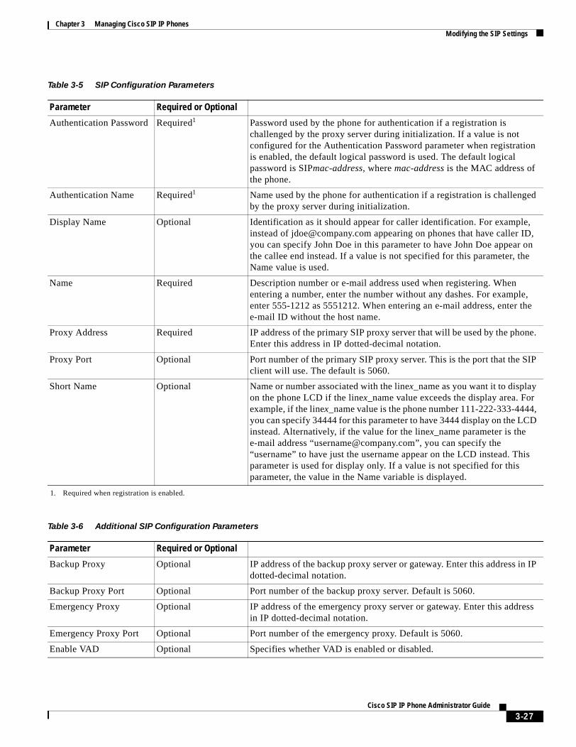
Chapter 3 Managing Cisco SIP IP PhonesModifying the SIP Settings
Table 3-5 SIP Configuration Parameters
Parameter Required or Optional
Authentication Password Required1
1. Required when registration is enabled.
Password used by the phone for authentication if a registration is challenged by the proxy server during initialization. If a value is not configured for the Authentication Password parameter when registration is enabled, the default logical password is used. The default logical password is SIPmac-address, where mac-address is the MAC address of the phone.
Authentication Name Required1 Name used by the phone for authentication if a registration is challenged by the proxy server during initialization.
Display Name Optional Identification as it should appear for caller identification. For example, instead of [email protected] appearing on phones that have caller ID, you can specify John Doe in this parameter to have John Doe appear on the callee end instead. If a value is not specified for this parameter, the Name value is used.
Name Required Description number or e-mail address used when registering. When entering a number, enter the number without any dashes. For example, enter 555-1212 as 5551212. When entering an e-mail address, enter the e-mail ID without the host name.
Proxy Address Required IP address of the primary SIP proxy server that will be used by the phone. Enter this address in IP dotted-decimal notation.
Proxy Port Optional Port number of the primary SIP proxy server. This is the port that the SIP client will use. The default is 5060.
Short Name Optional Name or number associated with the linex_name as you want it to display on the phone LCD if the linex_name value exceeds the display area. For example, if the linex_name value is the phone number 111-222-333-4444, you can specify 34444 for this parameter to have 3444 display on the LCD instead. Alternatively, if the value for the linex_name parameter is the e-mail address “[email protected]”, you can specify the “username” to have just the username appear on the LCD instead. This parameter is used for display only. If a value is not specified for this parameter, the value in the Name variable is displayed.
Table 3-6 Additional SIP Configuration Parameters
Parameter Required or Optional
Backup Proxy Optional IP address of the backup proxy server or gateway. Enter this address in IP dotted-decimal notation.
Backup Proxy Port Optional Port number of the backup proxy server. Default is 5060.
Emergency Proxy Optional IP address of the emergency proxy server or gateway. Enter this address in IP dotted-decimal notation.
Emergency Proxy Port Optional Port number of the emergency proxy. Default is 5060.
Enable VAD Optional Specifies whether VAD is enabled or disabled.
3-27Cisco SIP IP Phone Administrator Guide
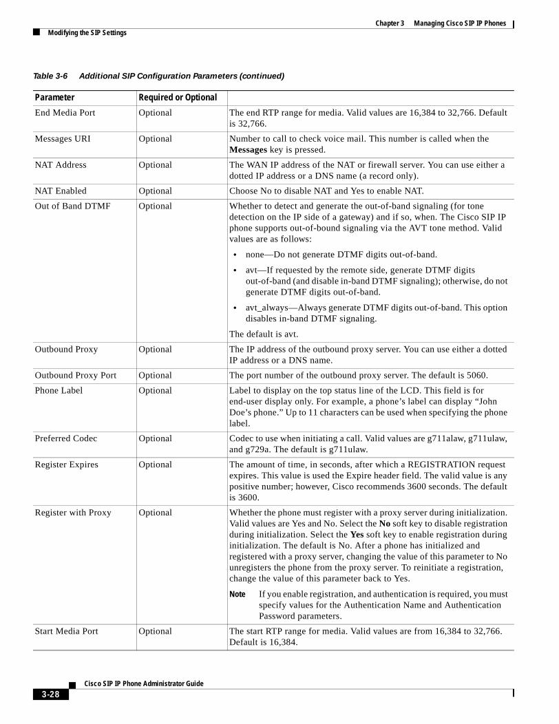
Chapter 3 Managing Cisco SIP IP PhonesModifying the SIP Settings
End Media Port Optional The end RTP range for media. Valid values are 16,384 to 32,766. Default is 32,766.
Messages URI Optional Number to call to check voice mail. This number is called when the Messages key is pressed.
NAT Address Optional The WAN IP address of the NAT or firewall server. You can use either a dotted IP address or a DNS name (a record only).
NAT Enabled Optional Choose No to disable NAT and Yes to enable NAT.
Out of Band DTMF Optional Whether to detect and generate the out-of-band signaling (for tone detection on the IP side of a gateway) and if so, when. The Cisco SIP IP phone supports out-of-bound signaling via the AVT tone method. Valid values are as follows:
• none—Do not generate DTMF digits out-of-band.
• avt—If requested by the remote side, generate DTMF digits out-of-band (and disable in-band DTMF signaling); otherwise, do not generate DTMF digits out-of-band.
• avt_always—Always generate DTMF digits out-of-band. This option disables in-band DTMF signaling.
The default is avt.
Outbound Proxy Optional The IP address of the outbound proxy server. You can use either a dotted IP address or a DNS name.
Outbound Proxy Port Optional The port number of the outbound proxy server. The default is 5060.
Phone Label Optional Label to display on the top status line of the LCD. This field is for end-user display only. For example, a phone’s label can display “John Doe’s phone.” Up to 11 characters can be used when specifying the phone label.
Preferred Codec Optional Codec to use when initiating a call. Valid values are g711alaw, g711ulaw, and g729a. The default is g711ulaw.
Register Expires Optional The amount of time, in seconds, after which a REGISTRATION request expires. This value is used the Expire header field. The valid value is any positive number; however, Cisco recommends 3600 seconds. The default is 3600.
Register with Proxy Optional Whether the phone must register with a proxy server during initialization. Valid values are Yes and No. Select the No soft key to disable registration during initialization. Select the Yes soft key to enable registration during initialization. The default is No. After a phone has initialized and registered with a proxy server, changing the value of this parameter to No unregisters the phone from the proxy server. To reinitiate a registration, change the value of this parameter back to Yes.
Note If you enable registration, and authentication is required, you must specify values for the Authentication Name and Authentication Password parameters.
Start Media Port Optional The start RTP range for media. Valid values are from 16,384 to 32,766. Default is 16,384.
Table 3-6 Additional SIP Configuration Parameters (continued)
Parameter Required or Optional
3-28Cisco SIP IP Phone Administrator Guide
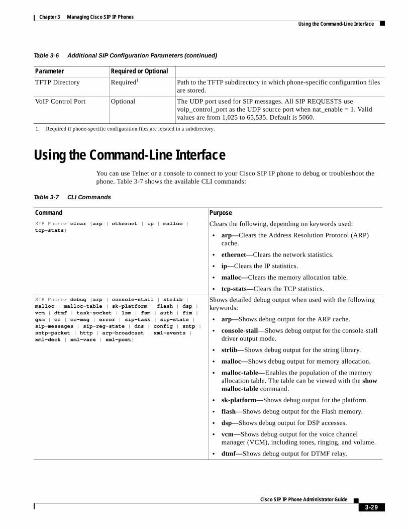
Chapter 3 Managing Cisco SIP IP PhonesUsing the Command-Line Interface
Using the Command-Line InterfaceYou can use Telnet or a console to connect to your Cisco SIP IP phone to debug or troubleshoot the phone. Table 3-7 shows the available CLI commands:
TFTP Directory Required1 Path to the TFTP subdirectory in which phone-specific configuration files are stored.
VoIP Control Port Optional The UDP port used for SIP messages. All SIP REQUESTS use voip_control_port as the UDP source port when nat_enable = 1. Valid values are from 1,025 to 65,535. Default is 5060.
1. Required if phone-specific configuration files are located in a subdirectory.
Table 3-6 Additional SIP Configuration Parameters (continued)
Parameter Required or Optional
Table 3-7 CLI Commands
Command PurposeSIP Phone> clear {arp | ethernet | ip | malloc | tcp-stats}
Clears the following, depending on keywords used:
• arp—Clears the Address Resolution Protocol (ARP) cache.
• ethernet—Clears the network statistics.
• ip—Clears the IP statistics.
• malloc—Clears the memory allocation table.
• tcp-stats—Clears the TCP statistics.
SIP Phone> debug {arp | console-stall | strlib | malloc | malloc-table | sk-platform | flash | dsp | vcm | dtmf | task-socket | lsm | fsm | auth | fim | gsm | cc | cc-msg | error | sip-task | sip-state | sip-messages | sip-reg-state | dns | config | sntp | sntp-packet | http | arp-broadcast | xml-events | xml-deck | xml-vars | xml-post}
Shows detailed debug output when used with the following keywords:
• arp—Shows debug output for the ARP cache.
• console-stall—Shows debug output for the console-stall driver output mode.
• strlib—Shows debug output for the string library.
• malloc—Shows debug output for memory allocation.
• malloc-table—Enables the population of the memory allocation table. The table can be viewed with the show malloc-table command.
• sk-platform—Shows debug output for the platform.
• flash—Shows debug output for the Flash memory.
• dsp—Shows debug output for DSP accesses.
• vcm—Shows debug output for the voice channel manager (VCM), including tones, ringing, and volume.
• dtmf—Shows debug output for DTMF relay.
3-29Cisco SIP IP Phone Administrator Guide
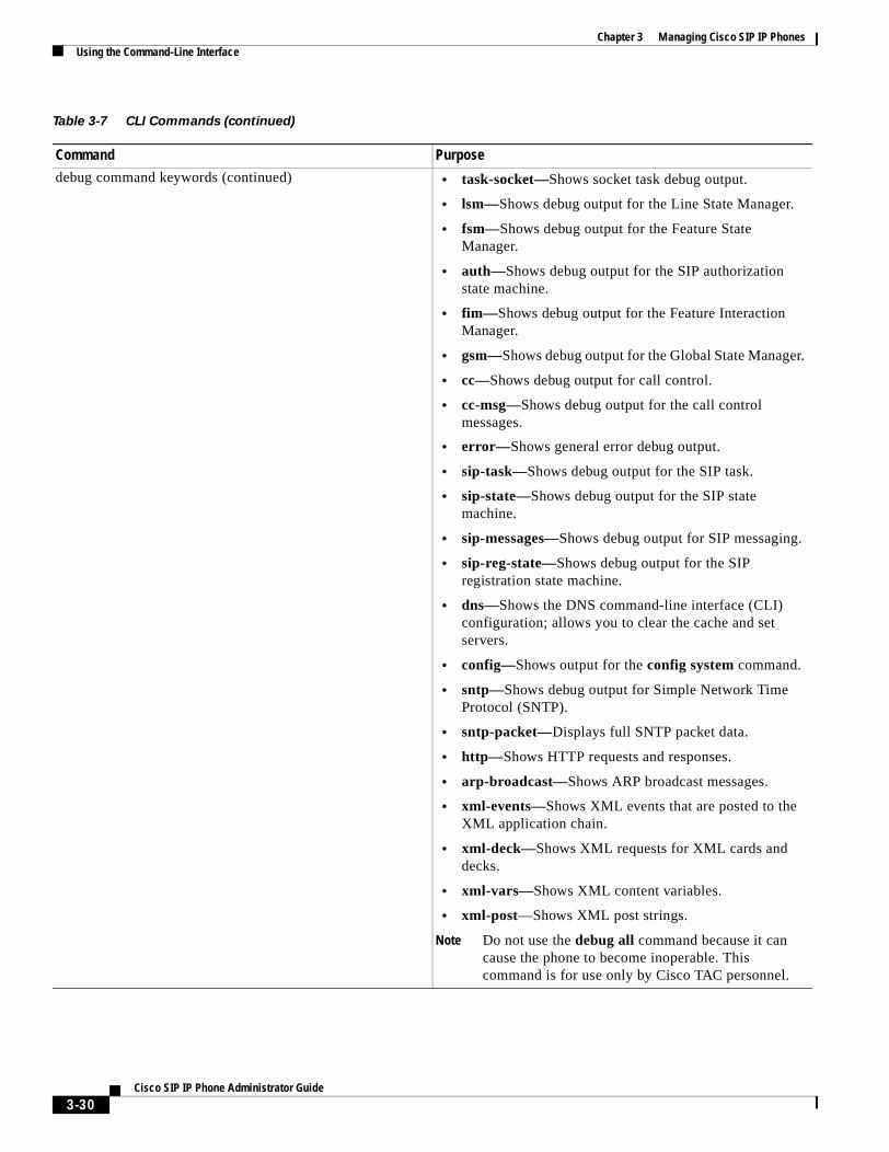
Chapter 3 Managing Cisco SIP IP PhonesUsing the Command-Line Interface
debug command keywords (continued) • task-socket—Shows socket task debug output.
• lsm—Shows debug output for the Line State Manager.
• fsm—Shows debug output for the Feature State Manager.
• auth—Shows debug output for the SIP authorization state machine.
• fim—Shows debug output for the Feature Interaction Manager.
• gsm—Shows debug output for the Global State Manager.
• cc—Shows debug output for call control.
• cc-msg—Shows debug output for the call control messages.
• error—Shows general error debug output.
• sip-task—Shows debug output for the SIP task.
• sip-state—Shows debug output for the SIP state machine.
• sip-messages—Shows debug output for SIP messaging.
• sip-reg-state—Shows debug output for the SIP registration state machine.
• dns—Shows the DNS command-line interface (CLI) configuration; allows you to clear the cache and set servers.
• config—Shows output for the config system command.
• sntp—Shows debug output for Simple Network Time Protocol (SNTP).
• sntp-packet—Displays full SNTP packet data.
• http—Shows HTTP requests and responses.
• arp-broadcast—Shows ARP broadcast messages.
• xml-events—Shows XML events that are posted to the XML application chain.
• xml-deck—Shows XML requests for XML cards and decks.
• xml-vars—Shows XML content variables.
• xml-post—Shows XML post strings.
Note Do not use the debug all command because it can cause the phone to become inoperable. This command is for use only by Cisco TAC personnel.
Table 3-7 CLI Commands (continued)
Command Purpose
3-30Cisco SIP IP Phone Administrator Guide
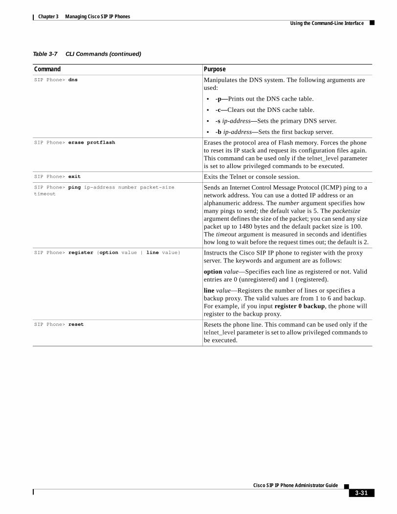
Chapter 3 Managing Cisco SIP IP PhonesUsing the Command-Line Interface
SIP Phone> dns Manipulates the DNS system. The following arguments are used:
• -p—Prints out the DNS cache table.
• -c—Clears out the DNS cache table.
• -s ip-address—Sets the primary DNS server.
• -b ip-address—Sets the first backup server.
SIP Phone> erase protflash Erases the protocol area of Flash memory. Forces the phone to reset its IP stack and request its configuration files again. This command can be used only if the telnet_level parameter is set to allow privileged commands to be executed.
SIP Phone> exit Exits the Telnet or console session.
SIP Phone> ping ip-address number packet-size timeout
Sends an Internet Control Message Protocol (ICMP) ping to a network address. You can use a dotted IP address or an alphanumeric address. The number argument specifies how many pings to send; the default value is 5. The packetsize argument defines the size of the packet; you can send any size packet up to 1480 bytes and the default packet size is 100. The timeout argument is measured in seconds and identifies how long to wait before the request times out; the default is 2.
SIP Phone> register {option value | line value} Instructs the Cisco SIP IP phone to register with the proxy server. The keywords and argument are as follows:
option value—Specifies each line as registered or not. Valid entries are 0 (unregistered) and 1 (registered).
line value—Registers the number of lines or specifies a backup proxy. The valid values are from 1 to 6 and backup. For example, if you input register 0 backup, the phone will register to the backup proxy.
SIP Phone> reset Resets the phone line. This command can be used only if the telnet_level parameter is set to allow privileged commands to be executed.
Table 3-7 CLI Commands (continued)
Command Purpose
3-31Cisco SIP IP Phone Administrator Guide
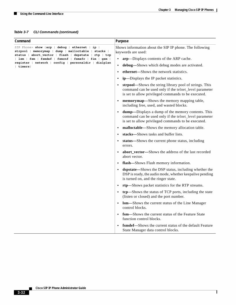
Chapter 3 Managing Cisco SIP IP PhonesUsing the Command-Line Interface
SIP Phone> show {arp | debug | ethernet | ip | strpool | memorymap | dump | malloctable | stacks | status | abort_vector | flash | dspstate | rtp | tcp | lsm | fsm | fsmdef | fsmcnf | fsmxfr | fim | gsm | register | network | config | personaldir | dialplan | timers}
Shows information about the SIP IP phone. The following keywords are used:
• arp—Displays contents of the ARP cache.
• debug—Shows which debug modes are activated.
• ethernet—Shows the network statistics.
• ip—Displays the IP packet statistics.
• strpool—Shows the string library pool of strings. This command can be used only if the telnet_level parameter is set to allow privileged commands to be executed.
• memorymap—Shows the memory mapping table, including free, used, and wasted blocks.
• dump—Displays a dump of the memory contents. This command can be used only if the telnet_level parameter is set to allow privileged commands to be executed.
• malloctable—Shows the memory allocation table.
• stacks—Shows tasks and buffer lists.
• status—Shows the current phone status, including errors.
• abort_vector—Shows the address of the last recorded abort vector.
• flash—Shows Flash memory information.
• dspstate—Shows the DSP status, including whether the DSP is ready, the audio mode, whether keepalive pending is turned on, and the ringer state.
• rtp—Shows packet statistics for the RTP streams.
• tcp—Shows the status of TCP ports, including the state (listen or closed) and the port number.
• lsm—Shows the current status of the Line Manager control blocks.
• fsm—Shows the current status of the Feature State function control blocks.
• fsmdef—Shows the current status of the default Feature State Manager data control blocks.
Table 3-7 CLI Commands (continued)
Command Purpose
3-32Cisco SIP IP Phone Administrator Guide
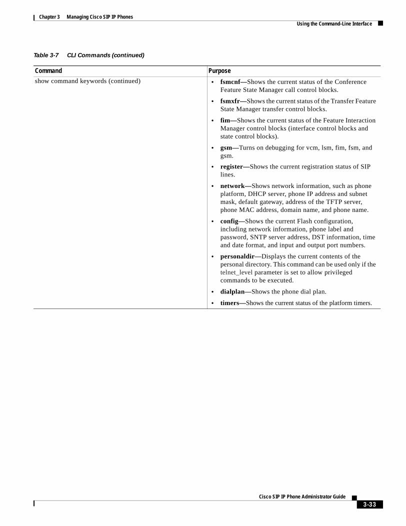
Chapter 3 Managing Cisco SIP IP PhonesUsing the Command-Line Interface
show command keywords (continued) • fsmcnf—Shows the current status of the Conference Feature State Manager call control blocks.
• fsmxfr—Shows the current status of the Transfer Feature State Manager transfer control blocks.
• fim—Shows the current status of the Feature Interaction Manager control blocks (interface control blocks and state control blocks).
• gsm—Turns on debugging for vcm, lsm, fim, fsm, and gsm.
• register—Shows the current registration status of SIP lines.
• network—Shows network information, such as phone platform, DHCP server, phone IP address and subnet mask, default gateway, address of the TFTP server, phone MAC address, domain name, and phone name.
• config—Shows the current Flash configuration, including network information, phone label and password, SNTP server address, DST information, time and date format, and input and output port numbers.
• personaldir—Displays the current contents of the personal directory. This command can be used only if the telnet_level parameter is set to allow privileged commands to be executed.
• dialplan—Shows the phone dial plan.
• timers—Shows the current status of the platform timers.
Table 3-7 CLI Commands (continued)
Command Purpose
3-33Cisco SIP IP Phone Administrator Guide
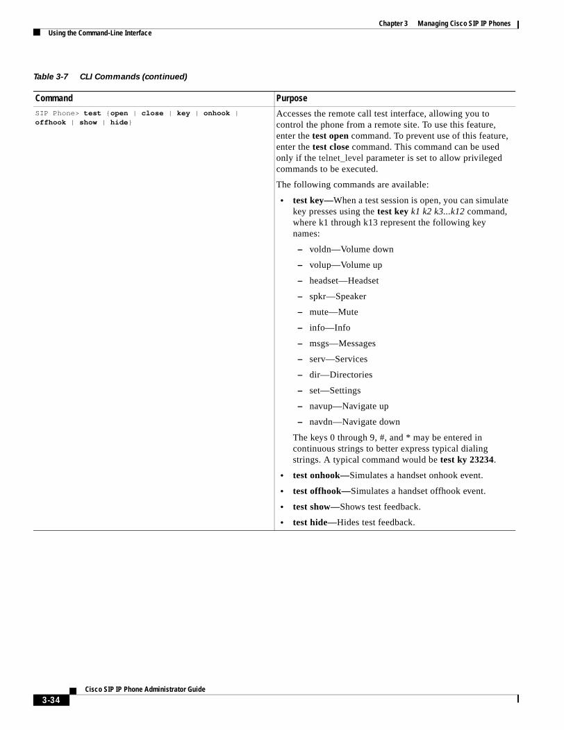
Chapter 3 Managing Cisco SIP IP PhonesUsing the Command-Line Interface
SIP Phone> test {open | close | key | onhook | offhook | show | hide}
Accesses the remote call test interface, allowing you to control the phone from a remote site. To use this feature, enter the test open command. To prevent use of this feature, enter the test close command. This command can be used only if the telnet_level parameter is set to allow privileged commands to be executed.
The following commands are available:
• test key—When a test session is open, you can simulate key presses using the test key k1 k2 k3...k12 command, where k1 through k13 represent the following key names:
– voldn—Volume down
– volup—Volume up
– headset—Headset
– spkr—Speaker
– mute—Mute
– info—Info
– msgs—Messages
– serv—Services
– dir—Directories
– set—Settings
– navup—Navigate up
– navdn—Navigate down
The keys 0 through 9, #, and * may be entered in continuous strings to better express typical dialing strings. A typical command would be test ky 23234.
• test onhook—Simulates a handset onhook event.
• test offhook—Simulates a handset offhook event.
• test show—Shows test feedback.
• test hide—Hides test feedback.
Table 3-7 CLI Commands (continued)
Command Purpose
3-34Cisco SIP IP Phone Administrator Guide
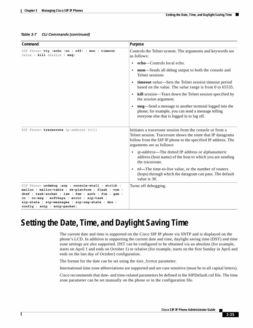
Chapter 3 Managing Cisco SIP IP PhonesSetting the Date, Time, and Daylight Saving Time
Setting the Date, Time, and Daylight Saving TimeThe current date and time is supported on the Cisco SIP IP phone via SNTP and is displayed on the phone’s LCD. In addition to supporting the current date and time, daylight saving time (DST) and time zone settings are also supported. DST can be configured to be obtained via an absolute (for example, starts on April 1 and ends on October 1) or relative (for example, starts on the first Sunday in April and ends on the last day of October) configuration.
The format for the date can be set using the date_format parameter.
International time zone abbreviations are supported and are case sensitive (must be in all capital letters).
Cisco recommends that date- and time-related parameters be defined in the SIPDefault.cnf file. The time zone parameter can be set manually on the phone or in the configuration file.
SIP Phone> tty {echo {on | off} | mon | timeout value | kill session | msg}
Controls the Telnet system. The arguments and keywords are as follows:
• echo—Controls local echo.
• mon—Sends all debug output to both the console and Telnet sessions.
• timeout value—Sets the Telnet session timeout period based on the value. The value range is from 0 to 65535.
• kill session—Tears down the Telnet session specified by the session argument.
• msg—Send a message to another terminal logged into the phone; for example, you can send a message telling everyone else that is logged in to log off.
SIP Phone> traceroute ip-address [ttl] Initiates a traceroute session from the console or from a Telnet session. Traceroute shows the route that IP datagrams follow from the SIP IP phone to the specified IP address. The arguments are as follows:
• ip-address—The dotted IP address or alphanumeric address (host name) of the host to which you are sending the traceroute.
• ttl—The time-to-live value, or the number of routers (hops) through which the datagram can pass. The default value is 30.
SIP Phone> undebug {arp | console-stall | strlib | malloc | malloc-table | sk-platform | flash | vcm | dtmf | task-socket | lsm | fsm | auth | fim | gsm | cc | cc-msg | softkeys | error | sip-task | sip-state | sip-messages | sip-reg-state | dns | config | sntp | sntp-packet}
Turns off debugging.
Table 3-7 CLI Commands (continued)
Command Purpose
3-35Cisco SIP IP Phone Administrator Guide
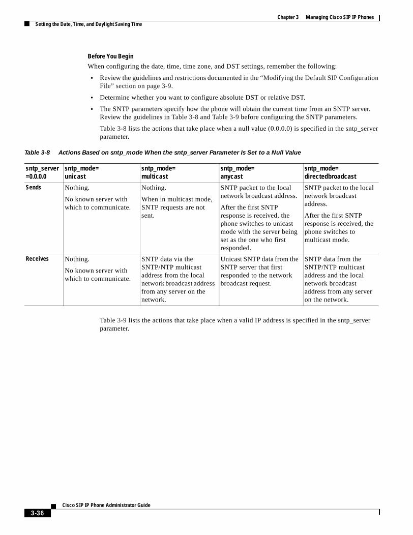
Chapter 3 Managing Cisco SIP IP PhonesSetting the Date, Time, and Daylight Saving Time
Before You Begin
When configuring the date, time, time zone, and DST settings, remember the following:
• Review the guidelines and restrictions documented in the “Modifying the Default SIP Configuration File” section on page 3-9.
• Determine whether you want to configure absolute DST or relative DST.
• The SNTP parameters specify how the phone will obtain the current time from an SNTP server. Review the guidelines in Table 3-8 and Table 3-9 before configuring the SNTP parameters.
Table 3-8 lists the actions that take place when a null value (0.0.0.0) is specified in the sntp_server parameter.
Table 3-9 lists the actions that take place when a valid IP address is specified in the sntp_server parameter.
Table 3-8 Actions Based on sntp_mode When the sntp_server Parameter Is Set to a Null Value
sntp_server=0.0.0.0
sntp_mode=unicast
sntp_mode=multicast
sntp_mode=anycast
sntp_mode=directedbroadcast
Sends Nothing.
No known server with which to communicate.
Nothing.
When in multicast mode, SNTP requests are not sent.
SNTP packet to the local network broadcast address.
After the first SNTP response is received, the phone switches to unicast mode with the server being set as the one who first responded.
SNTP packet to the local network broadcast address.
After the first SNTP response is received, the phone switches to multicast mode.
Receives Nothing.
No known server with which to communicate.
SNTP data via the SNTP/NTP multicast address from the local network broadcast address from any server on the network.
Unicast SNTP data from the SNTP server that first responded to the network broadcast request.
SNTP data from the SNTP/NTP multicast address and the local network broadcast address from any server on the network.
3-36Cisco SIP IP Phone Administrator Guide
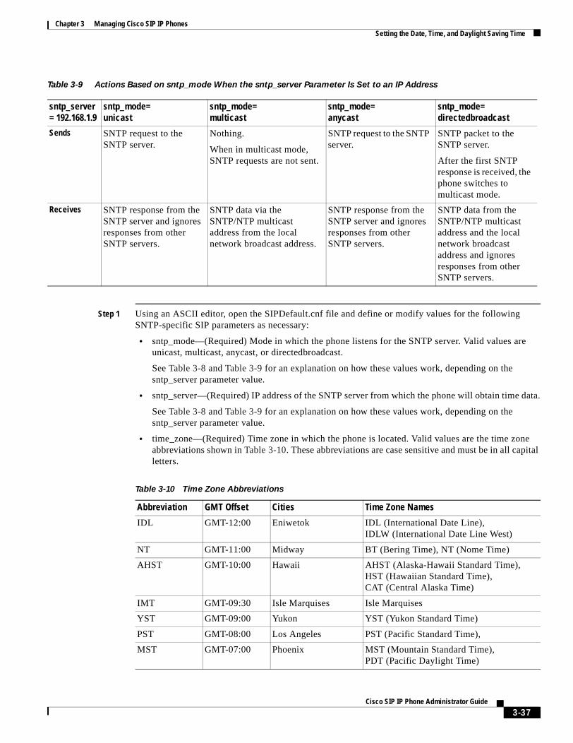
Chapter 3 Managing Cisco SIP IP PhonesSetting the Date, Time, and Daylight Saving Time
Step 1 Using an ASCII editor, open the SIPDefault.cnf file and define or modify values for the following SNTP-specific SIP parameters as necessary:
• sntp_mode—(Required) Mode in which the phone listens for the SNTP server. Valid values are unicast, multicast, anycast, or directedbroadcast.
See Table 3-8 and Table 3-9 for an explanation on how these values work, depending on the sntp_server parameter value.
• sntp_server—(Required) IP address of the SNTP server from which the phone will obtain time data.
See Table 3-8 and Table 3-9 for an explanation on how these values work, depending on the sntp_server parameter value.
• time_zone—(Required) Time zone in which the phone is located. Valid values are the time zone abbreviations shown in Table 3-10. These abbreviations are case sensitive and must be in all capital letters.
Table 3-9 Actions Based on sntp_mode When the sntp_server Parameter Is Set to an IP Address
sntp_server= 192.168.1.9
sntp_mode=unicast
sntp_mode=multicast
sntp_mode=anycast
sntp_mode=directedbroadcast
Sends SNTP request to the SNTP server.
Nothing.
When in multicast mode, SNTP requests are not sent.
SNTP request to the SNTP server.
SNTP packet to the SNTP server.
After the first SNTP response is received, the phone switches to multicast mode.
Receives SNTP response from the SNTP server and ignores responses from other SNTP servers.
SNTP data via the SNTP/NTP multicast address from the local network broadcast address.
SNTP response from the SNTP server and ignores responses from other SNTP servers.
SNTP data from the SNTP/NTP multicast address and the local network broadcast address and ignores responses from other SNTP servers.
Table 3-10 Time Zone Abbreviations
Abbreviation GMT Offset Cities Time Zone Names
IDL GMT-12:00 Eniwetok IDL (International Date Line), IDLW (International Date Line West)
NT GMT-11:00 Midway BT (Bering Time), NT (Nome Time)
AHST GMT-10:00 Hawaii AHST (Alaska-Hawaii Standard Time), HST (Hawaiian Standard Time), CAT (Central Alaska Time)
IMT GMT-09:30 Isle Marquises Isle Marquises
YST GMT-09:00 Yukon YST (Yukon Standard Time)
PST GMT-08:00 Los Angeles PST (Pacific Standard Time),
MST GMT-07:00 Phoenix MST (Mountain Standard Time), PDT (Pacific Daylight Time)
3-37Cisco SIP IP Phone Administrator Guide
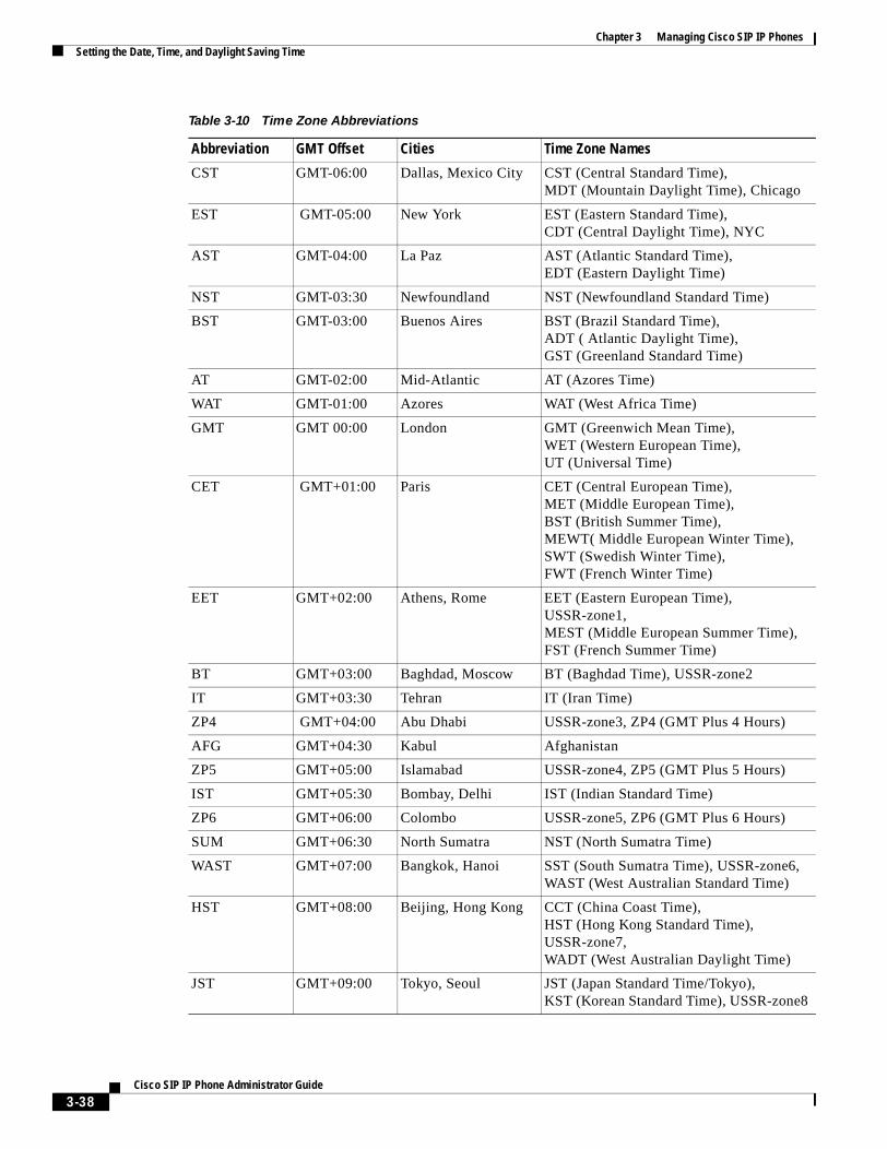
Chapter 3 Managing Cisco SIP IP PhonesSetting the Date, Time, and Daylight Saving Time
CST GMT-06:00 Dallas, Mexico City CST (Central Standard Time), MDT (Mountain Daylight Time), Chicago
EST GMT-05:00 New York EST (Eastern Standard Time), CDT (Central Daylight Time), NYC
AST GMT-04:00 La Paz AST (Atlantic Standard Time), EDT (Eastern Daylight Time)
NST GMT-03:30 Newfoundland NST (Newfoundland Standard Time)
BST GMT-03:00 Buenos Aires BST (Brazil Standard Time), ADT ( Atlantic Daylight Time),GST (Greenland Standard Time)
AT GMT-02:00 Mid-Atlantic AT (Azores Time)
WAT GMT-01:00 Azores WAT (West Africa Time)
GMT GMT 00:00 London GMT (Greenwich Mean Time), WET (Western European Time), UT (Universal Time)
CET GMT+01:00 Paris CET (Central European Time),MET (Middle European Time),BST (British Summer Time),MEWT( Middle European Winter Time),SWT (Swedish Winter Time),FWT (French Winter Time)
EET GMT+02:00 Athens, Rome EET (Eastern European Time),USSR-zone1, MEST (Middle European Summer Time), FST (French Summer Time)
BT GMT+03:00 Baghdad, Moscow BT (Baghdad Time), USSR-zone2
IT GMT+03:30 Tehran IT (Iran Time)
ZP4 GMT+04:00 Abu Dhabi USSR-zone3, ZP4 (GMT Plus 4 Hours)
AFG GMT+04:30 Kabul Afghanistan
ZP5 GMT+05:00 Islamabad USSR-zone4, ZP5 (GMT Plus 5 Hours)
IST GMT+05:30 Bombay, Delhi IST (Indian Standard Time)
ZP6 GMT+06:00 Colombo USSR-zone5, ZP6 (GMT Plus 6 Hours)
SUM GMT+06:30 North Sumatra NST (North Sumatra Time)
WAST GMT+07:00 Bangkok, Hanoi SST (South Sumatra Time), USSR-zone6, WAST (West Australian Standard Time)
HST GMT+08:00 Beijing, Hong Kong CCT (China Coast Time),HST (Hong Kong Standard Time), USSR-zone7, WADT (West Australian Daylight Time)
JST GMT+09:00 Tokyo, Seoul JST (Japan Standard Time/Tokyo), KST (Korean Standard Time), USSR-zone8
Table 3-10 Time Zone Abbreviations
Abbreviation GMT Offset Cities Time Zone Names
3-38Cisco SIP IP Phone Administrator Guide
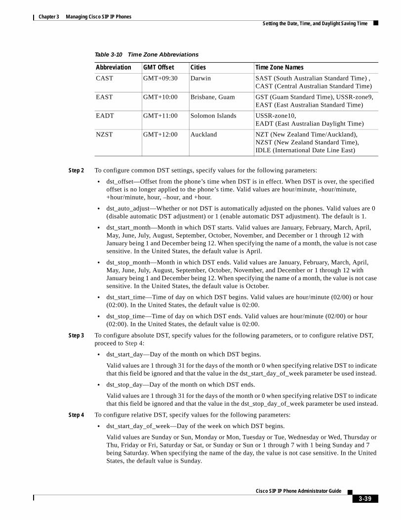
Chapter 3 Managing Cisco SIP IP PhonesSetting the Date, Time, and Daylight Saving Time
Step 2 To configure common DST settings, specify values for the following parameters:
• dst_offset—Offset from the phone’s time when DST is in effect. When DST is over, the specified offset is no longer applied to the phone’s time. Valid values are hour/minute, -hour/minute, +hour/minute, hour, –hour, and +hour.
• dst_auto_adjust—Whether or not DST is automatically adjusted on the phones. Valid values are 0 (disable automatic DST adjustment) or 1 (enable automatic DST adjustment). The default is 1.
• dst_start_month—Month in which DST starts. Valid values are January, February, March, April, May, June, July, August, September, October, November, and December or 1 through 12 with January being 1 and December being 12. When specifying the name of a month, the value is not case sensitive. In the United States, the default value is April.
• dst_stop_month—Month in which DST ends. Valid values are January, February, March, April, May, June, July, August, September, October, November, and December or 1 through 12 with January being 1 and December being 12. When specifying the name of a month, the value is not case sensitive. In the United States, the default value is October.
• dst_start_time—Time of day on which DST begins. Valid values are hour/minute (02/00) or hour (02:00). In the United States, the default value is 02:00.
• dst_stop_time—Time of day on which DST ends. Valid values are hour/minute (02/00) or hour (02:00). In the United States, the default value is 02:00.
Step 3 To configure absolute DST, specify values for the following parameters, or to configure relative DST, proceed to Step 4:
• dst_start_day—Day of the month on which DST begins.
Valid values are 1 through 31 for the days of the month or 0 when specifying relative DST to indicate that this field be ignored and that the value in the dst_start_day_of_week parameter be used instead.
• dst_stop_day—Day of the month on which DST ends.
Valid values are 1 through 31 for the days of the month or 0 when specifying relative DST to indicate that this field be ignored and that the value in the dst_stop_day_of_week parameter be used instead.
Step 4 To configure relative DST, specify values for the following parameters:
• dst_start_day_of_week—Day of the week on which DST begins.
Valid values are Sunday or Sun, Monday or Mon, Tuesday or Tue, Wednesday or Wed, Thursday or Thu, Friday or Fri, Saturday or Sat, or Sunday or Sun or 1 through 7 with 1 being Sunday and 7 being Saturday. When specifying the name of the day, the value is not case sensitive. In the United States, the default value is Sunday.
CAST GMT+09:30 Darwin SAST (South Australian Standard Time) , CAST (Central Australian Standard Time)
EAST GMT+10:00 Brisbane, Guam GST (Guam Standard Time), USSR-zone9, EAST (East Australian Standard Time)
EADT GMT+11:00 Solomon Islands USSR-zone10, EADT (East Australian Daylight Time)
NZST GMT+12:00 Auckland NZT (New Zealand Time/Auckland), NZST (New Zealand Standard Time),IDLE (International Date Line East)
Table 3-10 Time Zone Abbreviations
Abbreviation GMT Offset Cities Time Zone Names
3-39Cisco SIP IP Phone Administrator Guide
Chapter 3 Managing Cisco SIP IP PhonesSetting the Date, Time, and Daylight Saving Time
• dst_start_week_of_month—Week of month on which DST begins.
Valid values are 1 through 6 and 8, with 1 being the first week and each number thereafter being subsequent weeks and 8 specifying the last week in the month regardless of which week the last week is. In the United States, the default value is 1.
• dst_stop_day_of_week—Day of the week on which DST ends.
Valid values are Sunday or Sun, Monday or Mon, Tuesday or Tue, Wednesday or Wed, Thursday or Thu, Friday or Fri, Saturday or Sat, or Sunday or Sun or 1 through 7, with 1 being Sunday and 7 being Saturday. When specifying the name of the day, the value is not case sensitive. In the United States, the default value is Sunday.
• dst_stop_week_of_month—Week of month on which DST ends.
Valid values are 1 through 6 and 8, with 1 being the first week and each number thereafter being subsequent weeks and 8 specifying the last week in the month regardless of which week the last week is. In the United States, the default value is 8.
Step 5 Save the file with the same filename, SIPDefault.cnf, to the root directory of your TFTP server.
The following is a sample configuration for an absolute DST configuration:
time_zone : PSTdst_offset : 01/00dst_start_month : Aprildst_start_day : 1dst_start_time : 02/00dst_stop_month : Octoberdst_stop_day : 1dst_stop_time : 02/00dst_stop_autoadjust : 1
The following is a sample configuration for a relative DST configuration:
time_zone : PSTdst_offset : 01/00dst_start_month : Aprildst_start_day : 0dst_start_day_of_week : Sundaydst_start_week_of_month : 1dst_start_time : 02/00dst_stop_month : Octoberdst_stop_day : 0dst_stop_day_of_week : Sundaydst_stop_week_of_month : 8dst_stop_time : 02/00dst_stop_autoadjust :
3-40Cisco SIP IP Phone Administrator Guide
Chapter 3 Managing Cisco SIP IP PhonesErasing the Locally Defined Settings
Erasing the Locally Defined SettingsYou can erase the locally defined network and SIP settings that have been configured in the phone.
Erasing the Locally Defined Network SettingsWhen you erase the locally defined network settings, the values are reset to the defaults.
Before You Begin
• Unlock configuration mode as described in the “Unlocking Configuration Mode” section on page 3-2.
• If DHCP has been disabled on a phone, clearing the phone’s settings reenables it.
• Select the Erase Config parameter by pressing the down arrow to scroll to and highlight the parameter or by pressing the number that represents the parameter (located to the left of the parameter name on the LCD).
Step 1 Press the settings key. The Settings menu appears.
Step 2 Highlight Network Configuration.
Step 3 Press the Select soft key. The Network Configuration settings are displayed.
Step 4 Highlight Erase Configuration.
Step 5 Press the Yes soft key.
Step 6 Press the Save soft key. The phone programs the new information into Flash memory and resets.
Erasing the Locally Defined SIP SettingsWhen you erase the locally defined SIP settings, the values are reset to the defaults.
Note If your system has been set up to have the phones retrieve their SIP parameters using a TFTP server, you must edit the configuration file in which a parameter is defined to delete the parameter. When deleting a parameter, remove the variable in the file or change its value to a null value “ ” or “UNPROVISIONED”. If both the variable and its value are removed, the phone uses the setting for that variable that it has stored in Flash memory.
Note If the telnet_level parameter is set to allow privileged commands to be executed, the entire SIP configuration can be erased. Use the erase_protflash command so that the phone can retrieve its configuration files.
Before You Begin
Unlock configuration mode as described in the “Unlocking Configuration Mode” section on page 3-2.
Step 1 Press the settings key. The Settings menu appears.
3-41Cisco SIP IP Phone Administrator Guide
Chapter 3 Managing Cisco SIP IP PhonesAccessing Status Information
Step 2 Highlight SIP Configuration.
Step 3 Press the Select soft key. The SIP Configuration settings are displayed.
Step 4 Highlight the parameter for which you want to erase the setting.
Step 5 Press the Edit soft key.
Step 6 Press the << soft key to delete the current value.
Step 7 Press the Validate soft key to save your change and exit the Edit panel.
Step 8 If modifying a line parameter, press the Back soft key to exit the Line Configuration panel.
Step 9 Press the Save soft key. The phone programs the new information into Flash memory and resets.
Accessing Status InformationThere are several types of status information that you can access via the settings key. The information that you can obtain via the settings key can aid in system management. To access status information, select settings and then select Status from the Settings menu. From the Status menu, the following three options are available:
• Status Messages—Displays diagnostic messages.
• Network Status—Displays performance messages.
• Firmware Version—Displays information about the current firmware version on the phone.
In addition to the status messages available via the Setting Status menu, you can also obtain status messages for a current call.
Viewing Status MessagesTo view status messages that you can use to diagnose network problems, perform the following steps:
Step 1 Press the Settings key. The Settings menu appears.
Step 2 Highlight Status.
Step 3 Press the Select soft key. The Setting Status menu appears.
Step 4 Highlight Status Messages.
Step 5 Press the Select soft key. The Status Messages panel appears.
Step 6 To exit the Status Messages panel, press the Exit soft key.
3-42Cisco SIP IP Phone Administrator Guide
Chapter 3 Managing Cisco SIP IP PhonesAccessing Status Information
Viewing Network StatisticsTo view statistical information about the phone and network performance, perform the following steps:
Step 1 Press the Settings key. The Settings menu appears.
Step 2 Highlight Status.
Step 3 Press the Select soft key. The Setting Status menu appears.
Step 4 Highlight Network Statistics.
Step 5 Press the Select soft key. The Network Statistics panel appears.
The following information is displayed on this panel:
• Rcv—Number of packets received by the phone; not through the switch.
• Xmit—Number of packets sent by the phone; not through the switch.
• REr—Number of packets received by the phone that contained errors.
• BCast—Number of broadcast packets received by the phone.
• Phone State Message—TCP messages indicating the state of the phone. Possible messages are:
– Phone Initialized—TCP connection has not gone down since the phone was powered on.
– Phone Closed TCP—TCP connection was closed by the phone.
– TCP Timeout—TCP connection was closed because of a retry timeout.
– Error Code—Error messages indicating unusual reasons the TCP connection was closed.
• Elapsed Time—Length of time (in days, hours, minutes, and seconds) since the last power cycle.
• Port 0 Full, 100—Indicates that the network is in a linked state and has autonegotiated a full-duplex 100-Mbps connection.
• Port 0 Half, 100—Indicates that the network is in a linked state and has autonegotiated a half-duplex 100-Mbps connection.
• Port 0 Full, 10—Indicates that the network is in a linked state and has autonegotiated a full-duplex 10-Mbps connection.
• Port 0 Half, 10—Indicates that the network is in a linked state and has autonegotiated a half-duplex 10-Mbps connection.
• Port 1 Full, 100—Indicates that the network is in a linked state and has autonegotiated a full-duplex 100-Mbps connection.
• Port 1 Half, 100—Indicates that the network is in a linked state and has autonegotiated a half-duplex 100-Mbps connection.
• Port 1 Full, 10—Indicates that the network is in a linked state and has autonegotiated a full-duplex 10-Mbps connection.
• Port 1 Half, 10—Indicates that the network is in a linked state and has autonegotiated a half-duplex 10-Mbps connection.
Step 6 To exit the Network Statistics panel, press the Exit soft key.
Note To reset the values displayed on the Network Statistics panel, power the phone off and on.
3-43Cisco SIP IP Phone Administrator Guide
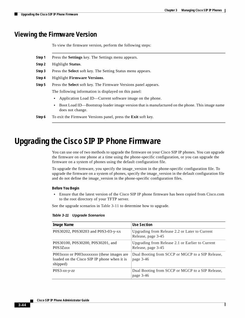
Chapter 3 Managing Cisco SIP IP PhonesUpgrading the Cisco SIP IP Phone Firmware
Viewing the Firmware VersionTo view the firmware version, perform the following steps:
Step 1 Press the Settings key. The Settings menu appears.
Step 2 Highlight Status.
Step 3 Press the Select soft key. The Setting Status menu appears.
Step 4 Highlight Firmware Versions.
Step 5 Press the Select soft key. The Firmware Versions panel appears.
The following information is displayed on this panel:
• Application Load ID—Current software image on the phone.
• Boot Load ID—Bootstrap loader image version that is manufactured on the phone. This image name does not change.
Step 6 To exit the Firmware Versions panel, press the Exit soft key.
Upgrading the Cisco SIP IP Phone FirmwareYou can use one of two methods to upgrade the firmware on your Cisco SIP IP phones. You can upgrade the firmware on one phone at a time using the phone-specific configuration, or you can upgrade the firmware on a system of phones using the default configuration file.
To upgrade the firmware, you specify the image_version in the phone-specific configuration file. To upgrade the firmware on a system of phones, specify the image_version in the default configuration file and do not define the image_version in the phone-specific configuration files.
Before You Begin
• Ensure that the latest version of the Cisco SIP IP phone firmware has been copied from Cisco.com to the root directory of your TFTP server.
See the upgrade scenarios in Table 3-11 to determine how to upgrade.
Table 3-11 Upgrade Scenarios
Image Name Use Section
P0S30202, P0S30203 and P0S3-03-y-xx Upgrading from Release 2.2 or Later to Current Release, page 3-45
P0S30100, P0S30200, P0S30201, and P0S3Zxxx
Upgrading from Release 2.1 or Earlier to Current Release, page 3-45
P003xxxx or P003xxxxxxxx (these images are loaded on the Cisco SIP IP phone when it is shipped)
Dual Booting from SCCP or MGCP to a SIP Release, page 3-46
P0S3-xx-y-zz Dual Booting from SCCP or MGCP to a SIP Release, page 3-46
3-44Cisco SIP IP Phone Administrator Guide
Chapter 3 Managing Cisco SIP IP PhonesUpgrading the Cisco SIP IP Phone Firmware
Upgrading from Release 2.2 or Later to Current Release
Step 1 Copy the new image P0S3-xx-y-zz.bin, where xx is the release major version, y is the release minor version, and zz is the maintenance number, from Cisco.com to the root directory of the TFTP server.
Step 2 Using a text editor, open the configuration file and update the image version specified in the image_version variable. The version name in the image_version variable should match the version name (without the .bin extension) of the latest firmware that you downloaded (for example, P0S3-xx-y-zz).
Step 3 Reset each phone.
The phone contacts the TFTP server and requests its configuration files. The phone compares the image defined in the file to the image that it has stored in Flash memory. If the phone determines that the image defined in the file differs from the image in Flash memory, it downloads the image defined in the configuration file (which is stored in the root directory on the TFTP server). Once the new image has been downloaded, the phone programs that image into Flash memory and then reboots.
Note If you do not define the image_version parameter in the default configuration file, only phones that have an updated phone-specific configuration file with the new image version and that have been restarted use the latest firmware image. All other phones use the older version until their configuration files have been updated with the new image version.
Upgrading from Release 2.1 or Earlier to Current Release
Step 1 Copy the P0S30202.bin binary image from Cisco.com to the root directory of the TFTP server.
Step 2 If you are dual booting from a Cisco IP phone running the Skinny Client Control Protocol (SCCP) or MGCP protocol, open the OS79XX.TXT file with a text editor and change the file to include P0S30202.
Step 3 Open the phone configuration file with a text editor and edit the image_version variable to read P0S30202.
Step 4 Reset each phone.
The phone contacts the TFTP server and requests its configuration files. The phone compares the image defined in the file to the image that it has stored in Flash memory. If the phone determines that the image defined in the file differs from the image in Flash memory, it downloads the image defined in the configuration file (which is stored in the root directory on the TFTP server). Once the new image has been downloaded, the phone programs that image into Flash memory and then reboots.
Step 5 Copy the new image P0S3-xx-y-zz.bin, where xx is the release major version, y is the release minor version, and zz is the maintenance number, from Cisco.com to the root directory of the TFTP server.
Step 6 Using a text editor, open the configuration file and update the image version specified in the image_version variable. The version name in image_version variable should match the version name (without the .bin extension) of the latest firmware that you downloaded (for example, P0S3-xx-y-zz).
Step 7 Reset each phone.
3-45Cisco SIP IP Phone Administrator Guide

Chapter 3 Managing Cisco SIP IP PhonesPerforming an Image Upgrade and Remote Reboot
Dual Booting from SCCP or MGCP to a SIP Release
Step 1 Copy the P0S30202.bin binary image from Cisco.com to the root directory of the TFTP server.
Step 2 If you are dual booting from a Cisco IP phone running the SCCP or MGCP protocol, open the OS79XX.TXT file with a text editor and change the file to include P0S30202.
Step 3 Copy the new image P0S3-xx-y-zz.bin, where xx is the release major version, y is the release minor version, and zz is the maintenance number, from Cisco.com to the root directory of the TFTP server.
Step 4 Using a text editor, open the configuration file and update the image version specified in the image_version variable. The version name in image_version variable should match the version name (without the .bin extension) of the latest firmware that you downloaded (for example, P0S3-xx-y-zz).
Step 5 Reset each phone.
The phone contacts the TFTP server and requests its configuration files. The phone compares the image defined in the file to the image that it has stored in Flash memory. If the phone determines that the image defined in the file differs from the image in Flash memory, it downloads the image defined in the configuration file (which is stored in the root directory on the TFTP server). Once the new image has been downloaded, the phone programs that image into Flash memory and then reboots.
Performing an Image Upgrade and Remote RebootWith Version 2.0 and newer of the Cisco SIP IP phone, you can perform an image upgrade and remote reboot using NOTIFY messages and the syncinfo.xml file. The dialplan.xml file can also be pushed down to the phones using a NOTIFY with a check-sync Event header.
Note To perform an image upgrade and remote reboot, a SIP proxy server and a TFTP server must exist in the phone network.
To upgrade the firmware image and perform a remote reboot, perform the following steps:
Step 1 Using an ASCII editor, open the SIPDefault.cnf file located in the root directory of your TFTP server and change the image_version parameter to the name of the latest image.
Step 2 Using an ASCII editor, open the syncinfo.xml file located in the root directory of your TFTP server and specify values for the image version and sync parameter as follows:
<IMAGE VERSION=”image_version” SYNC=”sync_number”/>
Where:
• image_version is the image version of the phone. The asterisk (*) can be used as a wildcard character.
• sync_number is the synchronization level of the phone. The default synchronization level for the phone is 1. A valid value is a character string of up to 32 characters.
3-46Cisco SIP IP Phone Administrator Guide
Chapter 3 Managing Cisco SIP IP PhonesPerforming an Image Upgrade and Remote Reboot
Step 3 Send a NOTIFY message to the phone. In the NOTIFY message, ensure that an Event header that is equal to “check-sync” is included. The following is a sample NOTIFY message:
NOTIFY sip:lineX_name@ipaddress:5060 SIP/2.0Via: SIP/2.0/UDP ipaddress:5060;branch=1Via: SIP/2.0/UDP ipaddressFrom: <sip:webadim@ipaddress>To: <sip:lineX_name@ipaddress>Event: check-syncDate: Mon, 10 Jul 2000 16:28:53 -0700Call-ID: 1349882@ipaddressCSeq: 1300 NOTIFYContact: <sip:webadmin@ipaddress>Content-Length: 0
After the remote reboot process is initiated on the phone via the NOTIFY message, the following actions take place:
1. If the phone is currently in an idle state, the phone waits 20 seconds and then contacts the TFTP server for the syncinfo.xml file. If the phone is not in an idle state, the phone waits until it is in an idle state for 20 seconds and then contacts the TFTP server for the syncinfo.xml file.
2. The phone reads the syncinfo.xml file and performs the following as appropriate:
a. Determines whether the current image is specified. If so, the phone proceeds to Step c. If not, the phone proceeds to Step b.
b. Determines whether there is a wildcard entry (*) in the image version parameter. If so, the phone proceeds to Step c. If not, the phone proceeds to Step d.
c. Determines if the synchronization value is different than what is stored on the phone. If so, the phone proceeds to Step e. If not, the phone proceeds to Step d.
d. The phone does nothing.
e. The phone reboots.
The phone the performs a normal reboot process as described in the “Overview of the Initialization Process” section on page 2-1, sees the new image, and upgrades to the new image with a synchronization value of what is specified in the syncinfo.xml file.
3-47Cisco SIP IP Phone Administrator Guide

Chapter 3 Managing Cisco SIP IP PhonesPerforming an Image Upgrade and Remote Reboot
3-48Cisco SIP IP Phone Administrator Guide
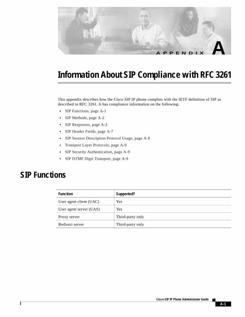
A P P E N D I X A
Information About SIP Compliance with RFC 3261This appendix describes how the Cisco SIP IP phone complies with the IETF definition of SIP as described in RFC 3261. It has compliance information on the following:
• SIP Functions, page A-1
• SIP Methods, page A-2
• SIP Responses, page A-2
• SIP Header Fields, page A-7
• SIP Session Description Protocol Usage, page A-8
• Transport Layer Protocols, page A-9
• SIP Security Authentication, page A-9
• SIP DTMF Digit Transport, page A-9
SIP Functions
Function Supported?
User agent client (UAC) Yes
User agent server (UAS) Yes
Proxy server Third-party only
Redirect server Third-party only
A-1Cisco SIP IP Phone Administrator Guide
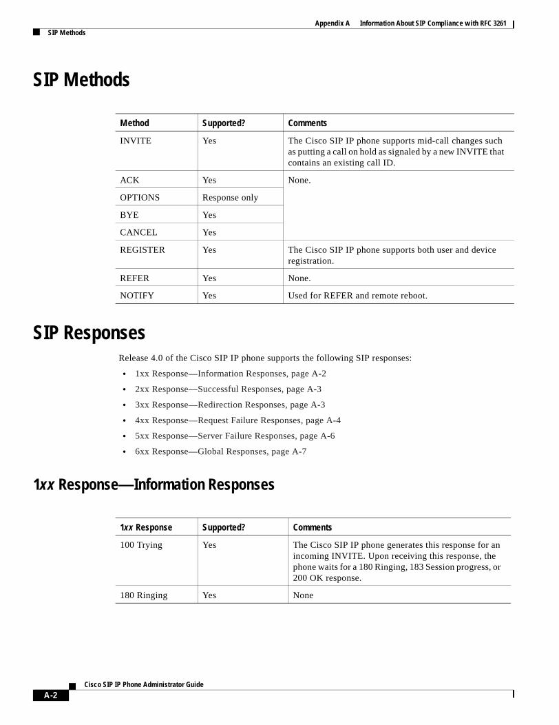
Appendix A Information About SIP Compliance with RFC 3261SIP Methods
SIP Methods
SIP ResponsesRelease 4.0 of the Cisco SIP IP phone supports the following SIP responses:
• 1xx Response—Information Responses, page A-2
• 2xx Response—Successful Responses, page A-3
• 3xx Response—Redirection Responses, page A-3
• 4xx Response—Request Failure Responses, page A-4
• 5xx Response—Server Failure Responses, page A-6
• 6xx Response—Global Responses, page A-7
1xx Response—Information Responses
Method Supported? Comments
INVITE Yes The Cisco SIP IP phone supports mid-call changes such as putting a call on hold as signaled by a new INVITE that contains an existing call ID.
ACK Yes None.
OPTIONS Response only
BYE Yes
CANCEL Yes
REGISTER Yes The Cisco SIP IP phone supports both user and device registration.
REFER Yes None.
NOTIFY Yes Used for REFER and remote reboot.
1xx Response Supported? Comments
100 Trying Yes The Cisco SIP IP phone generates this response for an incoming INVITE. Upon receiving this response, the phone waits for a 180 Ringing, 183 Session progress, or 200 OK response.
180 Ringing Yes None
A-2Cisco SIP IP Phone Administrator Guide
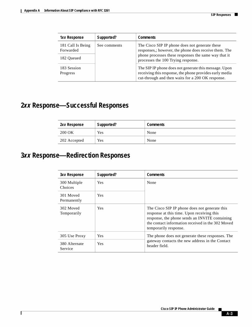
Appendix A Information About SIP Compliance with RFC 3261SIP Responses
2xx Response—Successful Responses
3xx Response—Redirection Responses
181 Call Is Being Forwarded
See comments The Cisco SIP IP phone does not generate these responses,; however, the phone does receive them. The phone processes these responses the same way that it processes the 100 Trying response.182 Queued
183 Session Progress
The SIP IP phone does not generate this message. Upon receiving this response, the phone provides early media cut-through and then waits for a 200 OK response.
1xx Response Supported? Comments
2xx Response Supported? Comments
200 OK Yes None
202 Accepted Yes None
3xx Response Supported? Comments
300 Multiple Choices
Yes None
301 Moved Permanently
Yes
302 Moved Temporarily
Yes The Cisco SIP IP phone does not generate this response at this time. Upon receiving this response, the phone sends an INVITE containing the contact information received in the 302 Moved temporarily response.
305 Use Proxy Yes The phone does not generate these responses. The gateway contacts the new address in the Contact header field.380 Alternate
ServiceYes
A-3Cisco SIP IP Phone Administrator Guide
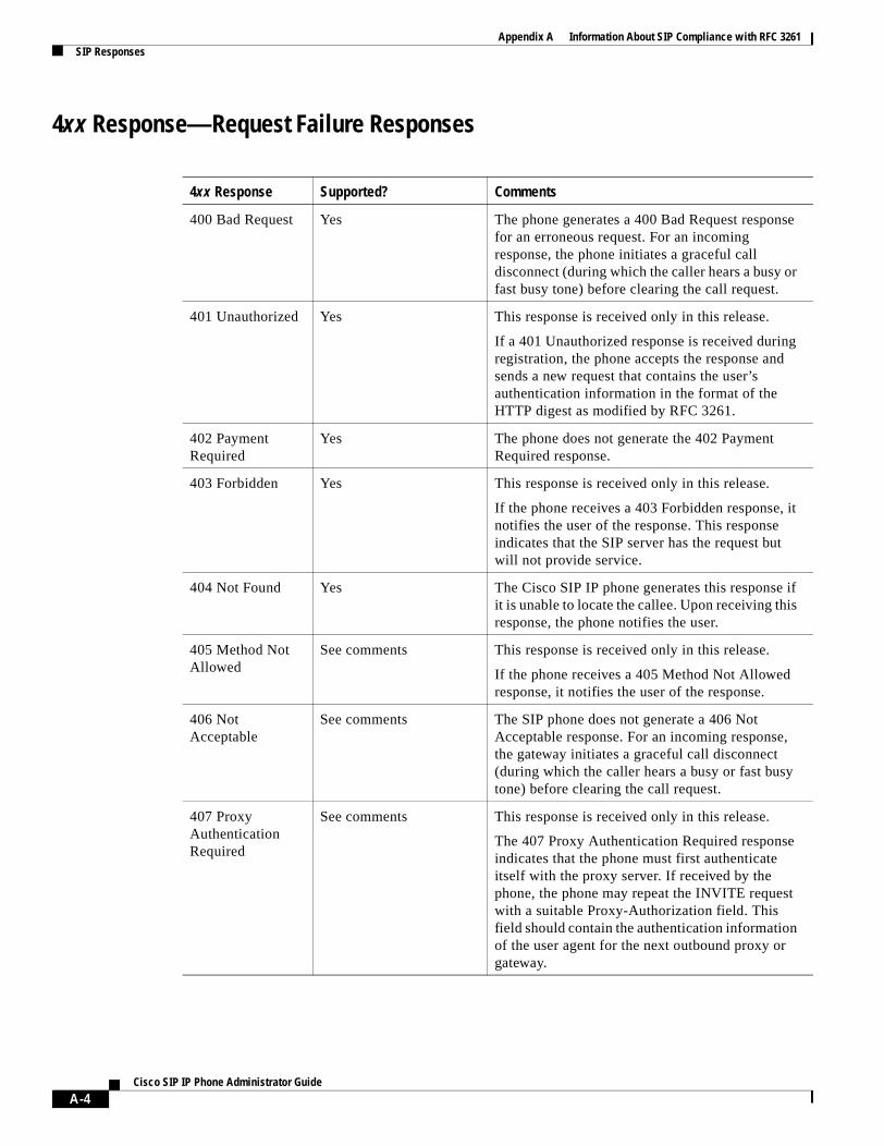
Appendix A Information About SIP Compliance with RFC 3261SIP Responses
4xx Response—Request Failure Responses
4xx Response Supported? Comments
400 Bad Request Yes The phone generates a 400 Bad Request response for an erroneous request. For an incoming response, the phone initiates a graceful call disconnect (during which the caller hears a busy or fast busy tone) before clearing the call request.
401 Unauthorized Yes This response is received only in this release.
If a 401 Unauthorized response is received during registration, the phone accepts the response and sends a new request that contains the user’s authentication information in the format of the HTTP digest as modified by RFC 3261.
402 Payment Required
Yes The phone does not generate the 402 Payment Required response.
403 Forbidden Yes This response is received only in this release.
If the phone receives a 403 Forbidden response, it notifies the user of the response. This response indicates that the SIP server has the request but will not provide service.
404 Not Found Yes The Cisco SIP IP phone generates this response if it is unable to locate the callee. Upon receiving this response, the phone notifies the user.
405 Method Not Allowed
See comments This response is received only in this release.
If the phone receives a 405 Method Not Allowed response, it notifies the user of the response.
406 Not Acceptable
See comments The SIP phone does not generate a 406 Not Acceptable response. For an incoming response, the gateway initiates a graceful call disconnect (during which the caller hears a busy or fast busy tone) before clearing the call request.
407 Proxy Authentication Required
See comments This response is received only in this release.
The 407 Proxy Authentication Required response indicates that the phone must first authenticate itself with the proxy server. If received by the phone, the phone may repeat the INVITE request with a suitable Proxy-Authorization field. This field should contain the authentication information of the user agent for the next outbound proxy or gateway.
A-4Cisco SIP IP Phone Administrator Guide
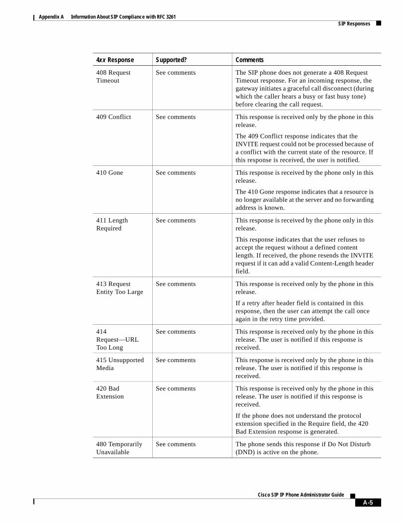
Appendix A Information About SIP Compliance with RFC 3261SIP Responses
408 Request Timeout
See comments The SIP phone does not generate a 408 Request Timeout response. For an incoming response, the gateway initiates a graceful call disconnect (during which the caller hears a busy or fast busy tone) before clearing the call request.
409 Conflict See comments This response is received only by the phone in this release.
The 409 Conflict response indicates that the INVITE request could not be processed because of a conflict with the current state of the resource. If this response is received, the user is notified.
410 Gone See comments This response is received by the phone only in this release.
The 410 Gone response indicates that a resource is no longer available at the server and no forwarding address is known.
411 Length Required
See comments This response is received by the phone only in this release.
This response indicates that the user refuses to accept the request without a defined content length. If received, the phone resends the INVITE request if it can add a valid Content-Length header field.
413 Request Entity Too Large
See comments This response is received only by the phone in this release.
If a retry after header field is contained in this response, then the user can attempt the call once again in the retry time provided.
414 Request—URL Too Long
See comments This response is received only by the phone in this release. The user is notified if this response is received.
415 Unsupported Media
See comments This response is received only by the phone in this release. The user is notified if this response is received.
420 Bad Extension
See comments This response is received only by the phone in this release. The user is notified if this response is received.
If the phone does not understand the protocol extension specified in the Require field, the 420 Bad Extension response is generated.
480 Temporarily Unavailable
See comments The phone sends this response if Do Not Disturb (DND) is active on the phone.
4xx Response Supported? Comments
A-5Cisco SIP IP Phone Administrator Guide
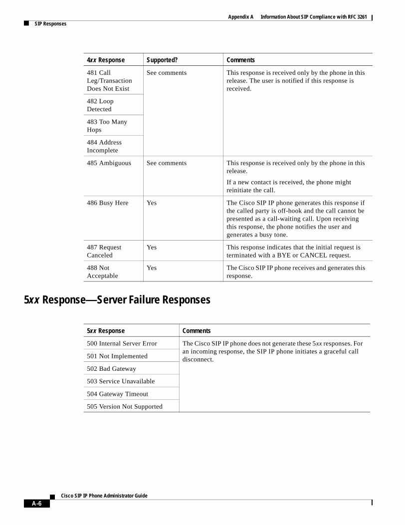
Appendix A Information About SIP Compliance with RFC 3261SIP Responses
5xx Response—Server Failure Responses
481 Call Leg/Transaction Does Not Exist
See comments This response is received only by the phone in this release. The user is notified if this response is received.
482 Loop Detected
483 Too Many Hops
484 Address Incomplete
485 Ambiguous See comments This response is received only by the phone in this release.
If a new contact is received, the phone might reinitiate the call.
486 Busy Here Yes The Cisco SIP IP phone generates this response if the called party is off-hook and the call cannot be presented as a call-waiting call. Upon receiving this response, the phone notifies the user and generates a busy tone.
487 Request Canceled
Yes This response indicates that the initial request is terminated with a BYE or CANCEL request.
488 Not Acceptable
Yes The Cisco SIP IP phone receives and generates this response.
5xx Response Comments
500 Internal Server Error The Cisco SIP IP phone does not generate these 5xx responses. For an incoming response, the SIP IP phone initiates a graceful call disconnect.501 Not Implemented
502 Bad Gateway
503 Service Unavailable
504 Gateway Timeout
505 Version Not Supported
4xx Response Supported? Comments
A-6Cisco SIP IP Phone Administrator Guide
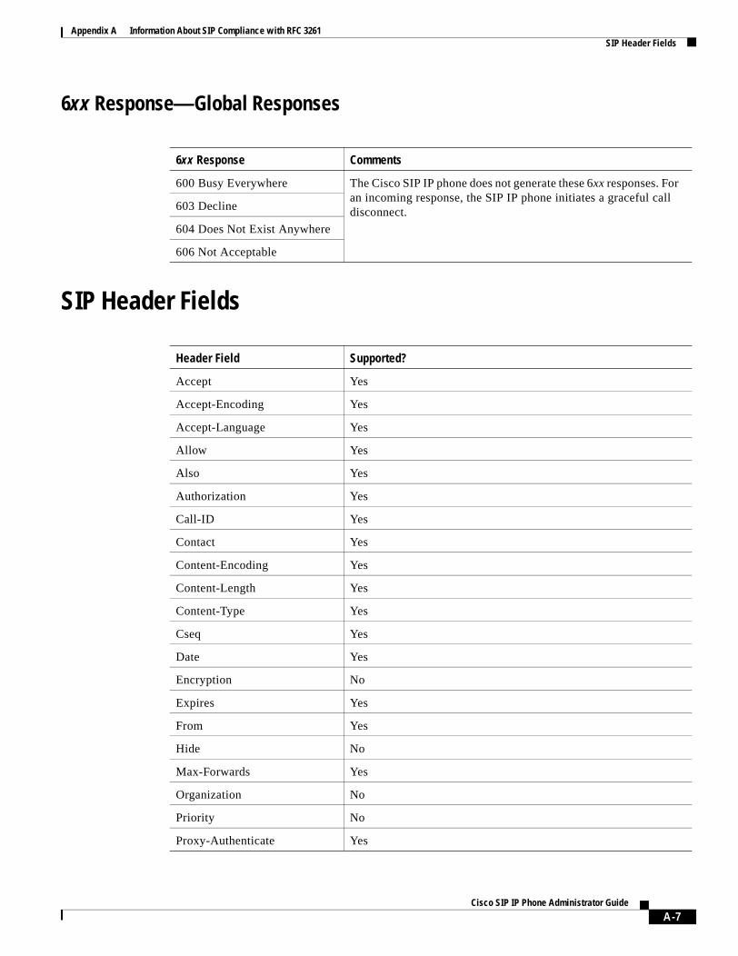
Appendix A Information About SIP Compliance with RFC 3261SIP Header Fields
6xx Response—Global Responses
SIP Header Fields
6xx Response Comments
600 Busy Everywhere The Cisco SIP IP phone does not generate these 6xx responses. For an incoming response, the SIP IP phone initiates a graceful call disconnect.603 Decline
604 Does Not Exist Anywhere
606 Not Acceptable
Header Field Supported?
Accept Yes
Accept-Encoding Yes
Accept-Language Yes
Allow Yes
Also Yes
Authorization Yes
Call-ID Yes
Contact Yes
Content-Encoding Yes
Content-Length Yes
Content-Type Yes
Cseq Yes
Date Yes
Encryption No
Expires Yes
From Yes
Hide No
Max-Forwards Yes
Organization No
Priority No
Proxy-Authenticate Yes
A-7Cisco SIP IP Phone Administrator Guide
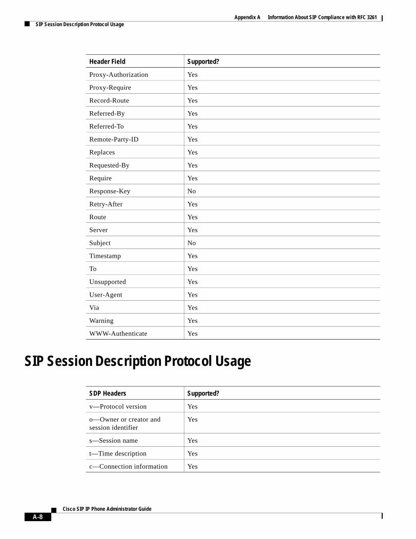
Appendix A Information About SIP Compliance with RFC 3261SIP Session Description Protocol Usage
SIP Session Description Protocol Usage
Proxy-Authorization Yes
Proxy-Require Yes
Record-Route Yes
Referred-By Yes
Referred-To Yes
Remote-Party-ID Yes
Replaces Yes
Requested-By Yes
Require Yes
Response-Key No
Retry-After Yes
Route Yes
Server Yes
Subject No
Timestamp Yes
To Yes
Unsupported Yes
User-Agent Yes
Via Yes
Warning Yes
WWW-Authenticate Yes
SDP Headers Supported?
v—Protocol version Yes
o—Owner or creator and session identifier
Yes
s—Session name Yes
t—Time description Yes
c—Connection information Yes
Header Field Supported?
A-8Cisco SIP IP Phone Administrator Guide
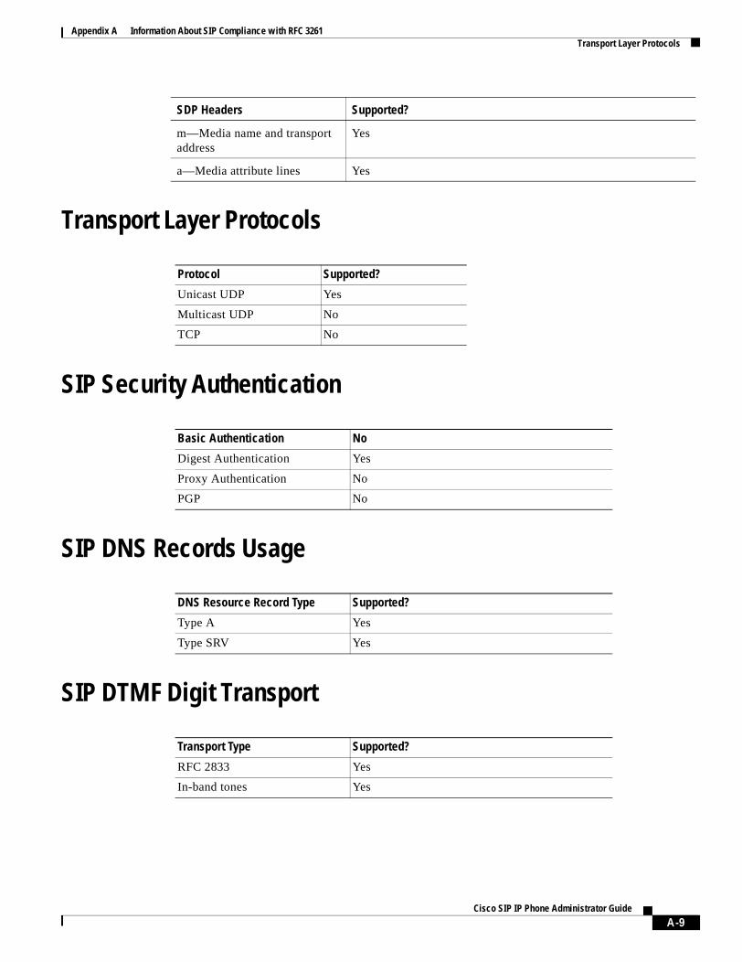
Appendix A Information About SIP Compliance with RFC 3261Transport Layer Protocols
Transport Layer Protocols
SIP Security Authentication
SIP DNS Records Usage
SIP DTMF Digit Transport
m—Media name and transport address
Yes
a—Media attribute lines Yes
Protocol Supported?
Unicast UDP Yes
Multicast UDP No
TCP No
Basic Authentication No
Digest Authentication Yes
Proxy Authentication No
PGP No
DNS Resource Record Type Supported?
Type A Yes
Type SRV Yes
Transport Type Supported?
RFC 2833 Yes
In-band tones Yes
SDP Headers Supported?
A-9Cisco SIP IP Phone Administrator Guide

Appendix A Information About SIP Compliance with RFC 3261SIP DTMF Digit Transport
A-10Cisco SIP IP Phone Administrator Guide
A P P E N D I X B
SIP Call FlowsThis appendix includes the following sections:
• Call Flow Scenarios for Successful Calls, page B-1
• Call Flow Scenarios for Failed Calls, page B-52
SIP uses the following request methods:
• INVITE—Indicates that a user or service is being invited to participate in a call session.
• ACK—Confirms that the client has received a final response to an INVITE request.
• BYE—Terminates a call and can be sent by either the caller or the callee.
• CANCEL—Cancels any pending searches but does not terminate a call that has already been accepted.
• OPTIONS—Queries the capabilities of servers.
• REGISTER—Registers the address listed in the To header field with a SIP server.
• REFER—Indicates that the user (recipient) should contact a third party for use in transferring parties.
• NOTIFY—Notifies the user of the status of a transfer using REFER. Also used for remote reset.
The following types of responses are used by SIP and generated by the Cisco SIP gateway:
• SIP 1xx—Informational Responses
• SIP 2xx—Successful Responses
• SIP 3xx—Redirection Responses
• SIP 4xx—Client Failure Responses
• SIP 5xx—Server Failure Responses
• SIP 6xx—Global Failure Responses
Call Flow Scenarios for Successful CallsThis section describes successful call flows scenarios, which are as follows:
• Gateway to Cisco SIP IP Phone, page B-2
• Cisco SIP IP Phone to Cisco SIP IP Phone, page B-7
B-1Cisco SIP IP Phone Administrator Guide
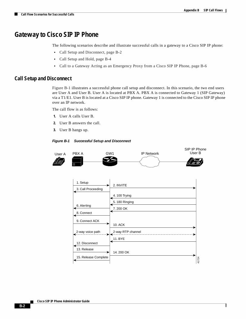
Appendix B SIP Call FlowsCall Flow Scenarios for Successful Calls
Gateway to Cisco SIP IP PhoneThe following scenarios describe and illustrate successful calls in a gateway to a Cisco SIP IP phone:
• Call Setup and Disconnect, page B-2
• Call Setup and Hold, page B-4
• Call to a Gateway Acting as an Emergency Proxy from a Cisco SIP IP Phone, page B-6
Call Setup and Disconnect
Figure B-1 illustrates a successful phone call setup and disconnect. In this scenario, the two end users are User A and User B. User A is located at PBX A. PBX A is connected to Gateway 1 (SIP Gateway) via a T1/E1. User B is located at a Cisco SIP IP phone. Gateway 1 is connected to the Cisco SIP IP phone over an IP network.
The call flow is as follows:
1. User A calls User B.
2. User B answers the call.
3. User B hangs up.
Figure B-1 Successful Setup and Disconnect
IP
3. Call Proceeding
6. Alerting
8. Connect
12. Disconnect
1. Setup
PBX ASIP IP Phone
User BUser A GW1 IP Network
4. 100 Trying
11. BYE
5. 180 Ringing
7. 200 OK
2. INVITE
2-way RTP channel2-way voice path
10. ACK
14. 200 OK
9. Connect ACK
13. Release
15. Release Complete
4172
4
B-2Cisco SIP IP Phone Administrator Guide
Appendix B SIP Call FlowsCall Flow Scenarios for Successful Calls
Step Action Description
1. Setup—PBX A to Gateway 1 Call Setup is initiated between PBX A and Gateway 1. The Call Setup includes the standard transactions that take place as User A attempts to call User B.
2. INVITE—Gateway 1 to Cisco SIP IP phone
Gateway 1 maps the SIP URL phone number to a dial peer. The dial peer includes the IP address and the port number of the SIP-enabled entity to contact. Gateway 1 sends a SIP INVITE request to the address it receives as the dial peer, which, in this scenario, is the Cisco SIP IP phone.
In the INVITE request:
• The IP address of the Cisco SIP IP phone is inserted in the Request-URI field.
• PBX A is identified as the call session initiator in the From field.
• A unique numeric identifier is assigned to the call and is inserted in the Call-ID field.
• The transaction number within a single call leg is identified in the CSeq field.
• The media capability User A is ready to receive is specified.
• The port on which the Gateway is prepared to receive the RTP data is specified.
3. Call Proceeding—Gateway 1 to PBX A
Gateway 1 sends a Call Proceeding message to PBX A to acknowledge the Call Setup request.
4. 100 Trying—Cisco SIP IP phone to Gateway 1
The Cisco SIP IP phone sends a SIP 100 Trying response to Gateway 1. The 100 Trying response indicates that the INVITE request has been received by the Cisco SIP IP phone.
5. 180 Ringing—Cisco SIP IP phone to Gateway 1
The Cisco SIP IP phone sends a SIP 180 Ringing response to Gateway 1. The 180 Ringing response indicates that the user is being alerted.
6. Alerting—Gateway 1 to PBX A Gateway 1 sends an Alert message to User A. The Alert message indicates that Gateway 1 has received a 180 Ringing response from the Cisco SIP IP phone. User A hears the ringback tone that indicates that User B is being alerted.
7. 200 OK—Cisco SIP IP phone to Gateway 1
The Cisco SIP IP phone sends a SIP 200 OK response to Gateway 1. The 200 OK response notifies Gateway 1 that the connection has been made.
8. Connect—Gateway 1 to PBX A Gateway 1 sends a Connect message to PBX A. The Connect message notifies PBX A that the connection has been made.
9. Connect ACK—PBX A to Gateway 1
PBX A acknowledges Gateway 1’s Connect message.
10. ACK—Gateway 1 to Cisco SIP IP phone
Gateway 1 sends a SIP ACK to the Cisco SIP IP phone. The ACK confirms that Gateway 1 has received the 200 OK response. The call session is now active.
11. BYE—Cisco SIP IP phone to Gateway 1
User B terminates the call session at his Cisco SIP IP phone and the phone sends a SIP BYE request to Gateway 1. The BYE request indicates that User B wants to release the call.
12. Disconnect—Gateway 1 to PBX A
Gateway 1 sends a Disconnect message to PBX A.
13. Release—PBX A to Gateway 1 PBX A sends a Release message to Gateway 1.
B-3Cisco SIP IP Phone Administrator Guide
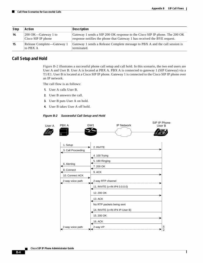
Appendix B SIP Call FlowsCall Flow Scenarios for Successful Calls
Call Setup and Hold
Figure B-2 illustrates a successful phone call setup and call hold. In this scenario, the two end users are User A and User B. User A is located at PBX A. PBX A is connected to gateway 1 (SIP Gateway) via a T1/E1. User B is located at a Cisco SIP IP phone. Gateway 1 is connected to the Cisco SIP IP phone over an IP network.
The call flow is as follows:
1. User A calls User B.
2. User B answers the call.
3. User B puts User A on hold.
4. User B takes User A off hold.
Figure B-2 Successful Call Setup and Hold
14. 200 OK—Gateway 1 to Cisco SIP IP phone
Gateway 1 sends a SIP 200 OK response to the Cisco SIP IP phone. The 200 OK response notifies the phone that Gateway 1 has received the BYE request.
15. Release Complete—Gateway 1 to PBX A
Gateway 1 sends a Release Complete message to PBX A and the call session is terminated.
Step Action Description
IP
SIP IP PhoneUser B
3. Call Proceeding
6. Alerting
8. Connect
10. Connect ACK
1. Setup
PBX AUser A GW1 IP Network
4. 100 Trying
13. ACK
16. ACK
11. INVITE (c=IN IP4 0.0.0.0)
14. INVITE (c=IN IP4 IP-User B)
5. 180 Ringing
7. 200 OK
2. INVITE
2-way RTP channel
No RTP packets being sent
2-way VP2-way voice path
2-way voice path
12. 200 OK
9. ACK
15. 200 OK
4172
8
B-4Cisco SIP IP Phone Administrator Guide
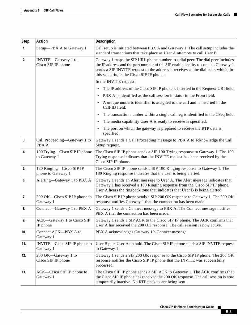
Appendix B SIP Call FlowsCall Flow Scenarios for Successful Calls
Step Action Description
1. Setup—PBX A to Gateway 1 Call setup is initiated between PBX A and Gateway 1. The call setup includes the standard transactions that take place as User A attempts to call User B.
2. INVITE—Gateway 1 to Cisco SIP IP phone
Gateway 1 maps the SIP URL phone number to a dial peer. The dial peer includes the IP address and the port number of the SIP enabled entity to contact. Gateway 1 sends a SIP INVITE request to the address it receives as the dial peer, which, in this scenario, is the Cisco SIP IP phone.
In the INVITE request:
• The IP address of the Cisco SIP IP phone is inserted in the Request-URI field.
• PBX A is identified as the call session initiator in the From field.
• A unique numeric identifier is assigned to the call and is inserted in the Call-ID field.
• The transaction number within a single call leg is identified in the CSeq field.
• The media capability User A is ready to receive is specified.
• The port on which the gateway is prepared to receive the RTP data is specified.
3. Call Proceeding—Gateway 1 to PBX A
Gateway 1 sends a Call Proceeding message to PBX A to acknowledge the Call Setup request.
4. 100 Trying—Cisco SIP IP phone to Gateway 1
The Cisco SIP IP phone sends a SIP 100 Trying response to Gateway 1. The 100 Trying response indicates that the INVITE request has been received by the Cisco SIP IP phone.
5. 180 Ringing—Cisco SIP IP phone to Gateway 1
The Cisco SIP IP phone sends a SIP 180 Ringing response to Gateway 1. The 180 Ringing response indicates that the user is being alerted.
6. Alerting—Gateway 1 to PBX A Gateway 1 sends an Alert message to User A. The Alert message indicates that Gateway 1 has received a 180 Ringing response from the Cisco SIP IP phone. User A hears the ringback tone that indicates that User B is being alerted.
7. 200 OK—Cisco SIP IP phone to Gateway 1
The Cisco SIP IP phone sends a SIP 200 OK response to Gateway 1. The 200 OK response notifies Gateway 1 that the connection has been made.
8. Connect—Gateway 1 to PBX A Gateway 1 sends a Connect message to PBX A. The Connect message notifies PBX A that the connection has been made.
9. ACK—Gateway 1 to Cisco SIP IP phone
Gateway 1 sends a SIP ACK to the Cisco SIP IP phone. The ACK confirms that User A has received the 200 OK response. The call session is now active.
10. Connect ACK—PBX A to Gateway 1
PBX A acknowledges Gateway 1’s Connect message.
11. INVITE—Cisco SIP IP phone to Gateway 1
User B puts User A on hold. The Cisco SIP IP phone sends a SIP INVITE request to Gateway 1.
12. 200 OK—Gateway 1 to Cisco SIP IP phone
Gateway 1 sends a SIP 200 OK response to the Cisco SIP IP phone. The 200 OK response notifies the Cisco SIP IP phone that the INVITE was successfully processed.
13. ACK—Cisco SIP IP phone to Gateway 1
The Cisco SIP IP phone sends a SIP ACK to Gateway 1. The ACK confirms that the Cisco SIP IP phone has received the 200 OK response. The call session is now temporarily inactive. No RTP packets are being sent.
B-5Cisco SIP IP Phone Administrator Guide
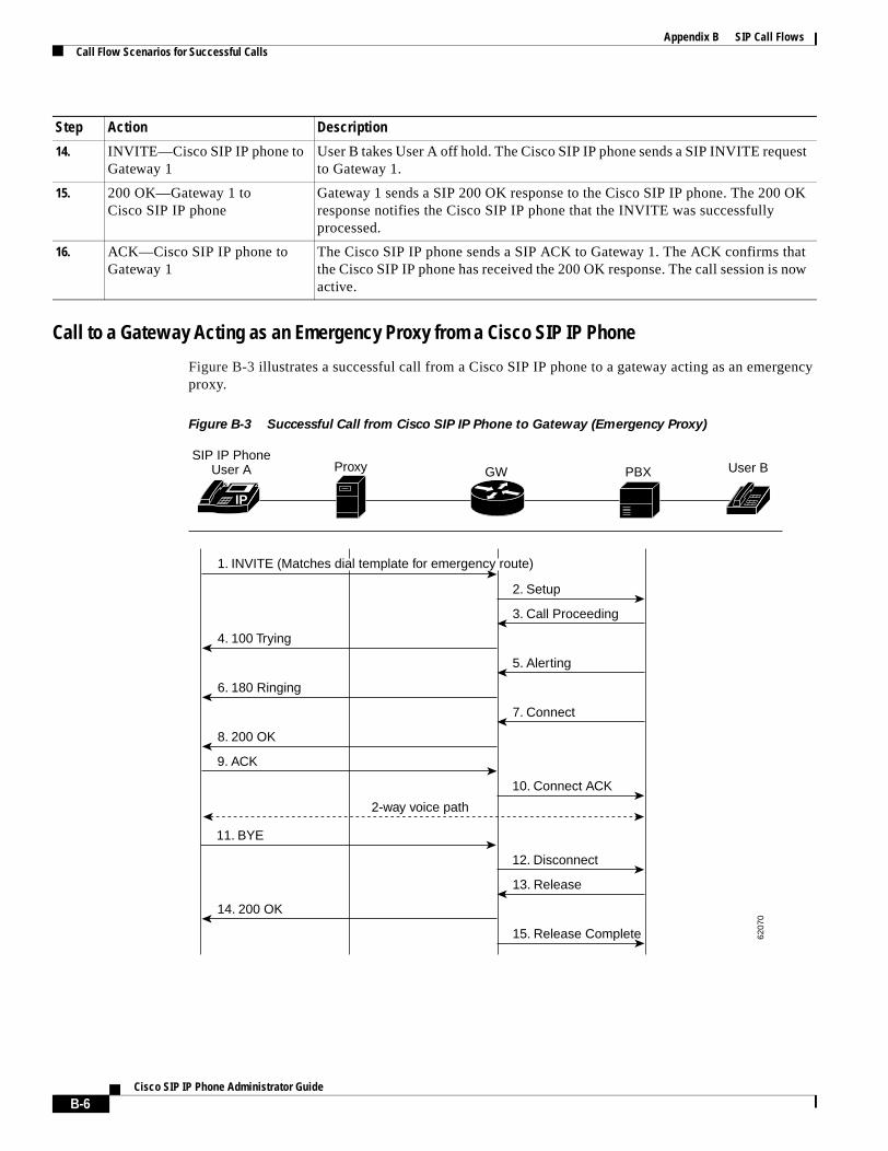
Appendix B SIP Call FlowsCall Flow Scenarios for Successful Calls
Call to a Gateway Acting as an Emergency Proxy from a Cisco SIP IP Phone
Figure B-3 illustrates a successful call from a Cisco SIP IP phone to a gateway acting as an emergency proxy.
Figure B-3 Successful Call from Cisco SIP IP Phone to Gateway (Emergency Proxy)
14. INVITE—Cisco SIP IP phone to Gateway 1
User B takes User A off hold. The Cisco SIP IP phone sends a SIP INVITE request to Gateway 1.
15. 200 OK—Gateway 1 to Cisco SIP IP phone
Gateway 1 sends a SIP 200 OK response to the Cisco SIP IP phone. The 200 OK response notifies the Cisco SIP IP phone that the INVITE was successfully processed.
16. ACK—Cisco SIP IP phone to Gateway 1
The Cisco SIP IP phone sends a SIP ACK to Gateway 1. The ACK confirms that the Cisco SIP IP phone has received the 200 OK response. The call session is now active.
Step Action Description
IP
SIP IP PhoneUser A Proxy
2. Setup
3. Call Proceeding
4. 100 Trying
5. Alerting
6. 180 Ringing
7. Connect
8. 200 OK
9. ACK
10. Connect ACK
11. BYE
12. Disconnect
13. Release
14. 200 OK
15. Release Complete
2-way voice path
GW PBX User B
6207
0
1. INVITE (Matches dial template for emergency route)
B-6Cisco SIP IP Phone Administrator Guide
Appendix B SIP Call FlowsCall Flow Scenarios for Successful Calls
Cisco SIP IP Phone to Cisco SIP IP PhoneThe following sections describe and illustrate successful calls from Cisco SIP IP phone to Cisco SIP IP phone:
• Simple Call Hold, page B-8
• Call Hold with Consultation, page B-10
• Call Waiting, page B-14
• Call Transfer Without Consultation, page B-18
• Call Transfer Without Consultation Using Failover, page B-22
• Call Transfer with Consultation, page B-25
• Call Transfer with Consultation Using Failover, page B-30
Step Action Description
1. INVITE—Cisco SIP IP phone to gateway (emergency proxy)
Cisco SIP IP phone tries to connect to the gateway (emergency proxy) by sending out the INVITE message. The dial template for the emergency route is matched.
2. Setup—Gateway to PBX Call setup is initiated between the gateway and PBX. The call setup includes the standard transactions that take place as User A attempts to call User B.
3. Call Proceeding—PBX to gateway
PBX sends a Call Proceeding message to gateway to acknowledge the Call Setup request.
4. 100 Trying—Gateway to Cisco SIP IP phone (User A)
Gateway sends a SIP 100 Trying response to User A. The 100 Trying response indicates that the INVITE request has been received by the gateway.
5. Alerting—PBX to gateway PBX sends an Alert message to the gateway. The Alert message indicates that the PBX has received a 100 Trying Ringing response from the gateway.
6. 180 Ringing—Gateway toCisco SIP IP phone (User A)
The gateway sends a SIP 180 Ringing response to User A. The 180 Ringing response indicates that the gateway is being alerted.
7. Connect—PBX to gateway PBX sends a Connect message to gateway. The Connect message notifies the gateway that the connection has been made.
8. 200 OK—Gateway to Cisco SIP IP phone (User A)
Gateway sends a SIP 200 OK response to the User A. The 200 OK response notifies User A that the connection has been made.
9. ACK—Cisco SIP IP phone (User A) to gateway
User A sends a SIP ACK to the gateway. The ACK confirms that User A has received the 200 OK response. The call session is now active.
10. Connect ACK—Gateway to PBX
Gateway acknowledges PBX’s Connect message.
11. BYE—Cisco SIP IP phone(User A) to gateway
User A terminates the call session and sends a SIP BYE request to gateway. The BYE request indicates that User A wants to release the call.
12. Disconnect—Gateway to PBX Gateway sends a Disconnect message to PBX.
13. Release—PBX to gateway PBX sends a Release message to the gateway.
14. 200 OK—Gateway to Cisco SIP IP phone (User A)
Gateway sends a SIP 200 OK response to User A. The 200 OK response notifies User A that the gateway has received the BYE request.
15. Release Complete—Gateway to PBX
Gateway sends a Release Complete message to the PBX and the call session is terminated.
B-7Cisco SIP IP Phone Administrator Guide
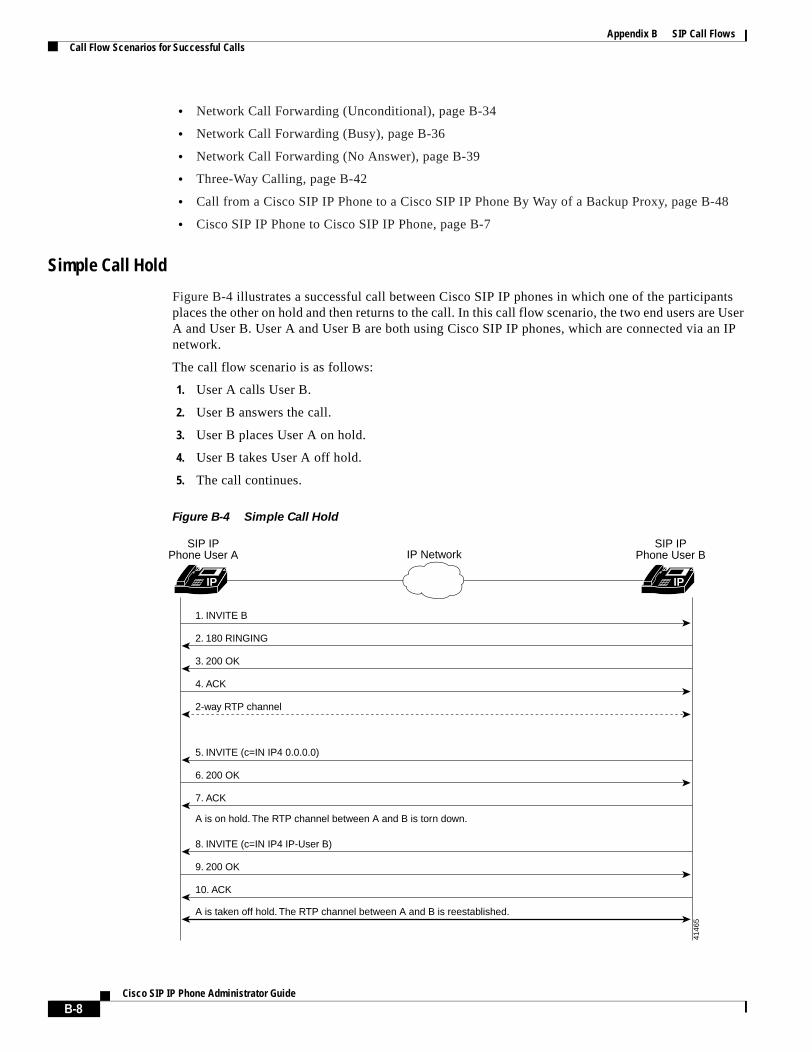
Appendix B SIP Call FlowsCall Flow Scenarios for Successful Calls
• Network Call Forwarding (Unconditional), page B-34
• Network Call Forwarding (Busy), page B-36
• Network Call Forwarding (No Answer), page B-39
• Three-Way Calling, page B-42
• Call from a Cisco SIP IP Phone to a Cisco SIP IP Phone By Way of a Backup Proxy, page B-48
• Cisco SIP IP Phone to Cisco SIP IP Phone, page B-7
Simple Call Hold
Figure B-4 illustrates a successful call between Cisco SIP IP phones in which one of the participants places the other on hold and then returns to the call. In this call flow scenario, the two end users are User A and User B. User A and User B are both using Cisco SIP IP phones, which are connected via an IP network.
The call flow scenario is as follows:
1. User A calls User B.
2. User B answers the call.
3. User B places User A on hold.
4. User B takes User A off hold.
5. The call continues.
Figure B-4 Simple Call Hold
IP IP
2. 180 RINGING
3. 200 OK
2-way RTP channel
4. ACK
A is taken off hold. The RTP channel between A and B is reestablished.
A is on hold. The RTP channel between A and B is torn down.
5. INVITE (c=IN IP4 0.0.0.0)
6. 200 OK
7. ACK
8. INVITE (c=IN IP4 IP-User B)
9. 200 OK
10. ACK
1. INVITE B
IP NetworkSIP IP
Phone User ASIP IP
Phone User B
4146
5
B-8Cisco SIP IP Phone Administrator Guide
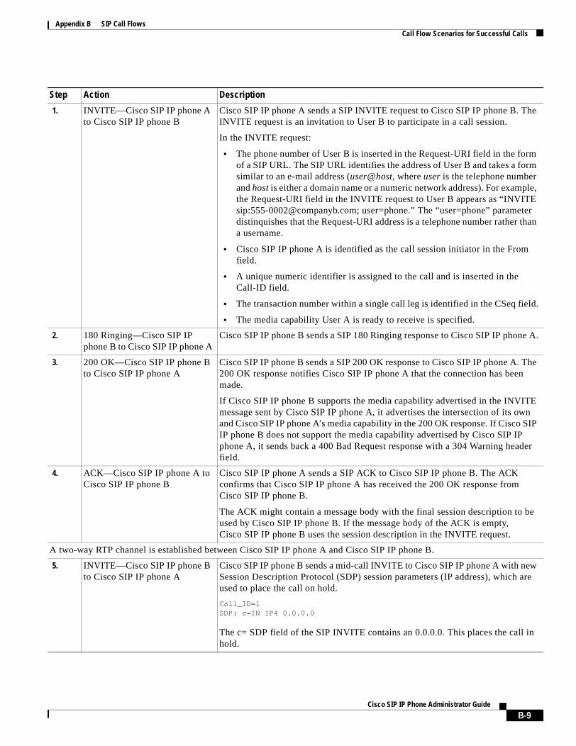
Appendix B SIP Call FlowsCall Flow Scenarios for Successful Calls
Step Action Description
1. INVITE—Cisco SIP IP phone A to Cisco SIP IP phone B
Cisco SIP IP phone A sends a SIP INVITE request to Cisco SIP IP phone B. The INVITE request is an invitation to User B to participate in a call session.
In the INVITE request:
• The phone number of User B is inserted in the Request-URI field in the form of a SIP URL. The SIP URL identifies the address of User B and takes a form similar to an e-mail address (user@host, where user is the telephone number and host is either a domain name or a numeric network address). For example, the Request-URI field in the INVITE request to User B appears as “INVITE sip:[email protected]; user=phone.” The “user=phone” parameter distinquishes that the Request-URI address is a telephone number rather than a username.
• Cisco SIP IP phone A is identified as the call session initiator in the From field.
• A unique numeric identifier is assigned to the call and is inserted in the Call-ID field.
• The transaction number within a single call leg is identified in the CSeq field.
• The media capability User A is ready to receive is specified.
2. 180 Ringing—Cisco SIP IP phone B to Cisco SIP IP phone A
Cisco SIP IP phone B sends a SIP 180 Ringing response to Cisco SIP IP phone A.
3. 200 OK—Cisco SIP IP phone B to Cisco SIP IP phone A
Cisco SIP IP phone B sends a SIP 200 OK response to Cisco SIP IP phone A. The 200 OK response notifies Cisco SIP IP phone A that the connection has been made.
If Cisco SIP IP phone B supports the media capability advertised in the INVITE message sent by Cisco SIP IP phone A, it advertises the intersection of its own and Cisco SIP IP phone A’s media capability in the 200 OK response. If Cisco SIP IP phone B does not support the media capability advertised by Cisco SIP IP phone A, it sends back a 400 Bad Request response with a 304 Warning header field.
4. ACK—Cisco SIP IP phone A to Cisco SIP IP phone B
Cisco SIP IP phone A sends a SIP ACK to Cisco SIP IP phone B. The ACK confirms that Cisco SIP IP phone A has received the 200 OK response from Cisco SIP IP phone B.
The ACK might contain a message body with the final session description to be used by Cisco SIP IP phone B. If the message body of the ACK is empty, Cisco SIP IP phone B uses the session description in the INVITE request.
A two-way RTP channel is established between Cisco SIP IP phone A and Cisco SIP IP phone B.
5. INVITE—Cisco SIP IP phone B to Cisco SIP IP phone A
Cisco SIP IP phone B sends a mid-call INVITE to Cisco SIP IP phone A with new Session Description Protocol (SDP) session parameters (IP address), which are used to place the call on hold.
Call_ID=1 SDP: c=IN IP4 0.0.0.0
The c= SDP field of the SIP INVITE contains an 0.0.0.0. This places the call in hold.
B-9Cisco SIP IP Phone Administrator Guide
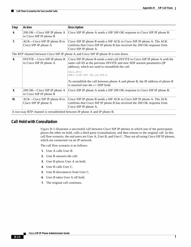
Appendix B SIP Call FlowsCall Flow Scenarios for Successful Calls
Call Hold with Consultation
Figure B-5 illustrates a successful call between Cisco SIP IP phones in which one of the participants places the other on hold, calls a third party (consultation), and then returns to the original call. In this call flow scenario, the end users are User A, User B, and User C. They are all using Cisco SIP IP phones, which are connected via an IP network.
The call flow scenario is as follows:
1. User A calls User B.
2. User B answers the call.
3. User B places User A on hold.
4. User B calls User C.
5. User B disconnects from User C.
6. User B takes User A off hold.
7. The original call continues.
6. 200 OK—Cisco SIP IP phone A to Cisco SIP IP phone B
Cisco SIP IP phone A sends a SIP 200 OK response to Cisco SIP IP phone B.
7. ACK—Cisco SIP IP phone B to Cisco SIP IP phone A
Cisco SIP IP phone B sends a SIP ACK to Cisco SIP IP phone A. The ACK confirms that Cisco SIP IP phone B has received the 200 OK response from Cisco SIP IP phone A.
The RTP channel between Cisco SIP IP phone A and Cisco SIP IP phone B is torn down.
8. INVITE—Cisco SIP IP phone B to Cisco SIP IP phone A
Cisco SIP IP phone B sends a mid-call INVITE to Cisco SIP IP phone A with the same call ID as the previous INVITE and new SDP session parameters (IP address), which are used to reestablish the call.
Call_ID=1 SDP: c=IN IP4 181.23.250.2
To reestablish the call between phone A and phone B, the IP address of phone B is inserted into the c= SDP field.
9. 200 OK—Cisco SIP IP phone A to Cisco SIP IP phone B
Cisco SIP IP phone A sends a SIP 200 OK response to Cisco SIP IP phone B.
10. ACK—Cisco SIP IP phone B to Cisco SIP IP phone A
Cisco SIP IP phone B sends a SIP ACK to Cisco SIP IP phone A. The ACK confirms that Cisco SIP IP phone B has received the 200 OK response from Cisco SIP IP phone A.
A two-way RTP channel is reestablished between IP phone A and IP phone B.
Step Action Description
B-10Cisco SIP IP Phone Administrator Guide

Appendix B SIP Call FlowsCall Flow Scenarios for Successful Calls
Figure B-5 Call Hold with Consultation
IP IP IP
2. 180 Ringing
3. 200 OK
2-way RTP channel
A is put on hold. The RTP channel between A and B is torn down.
4. ACK
2-way RTP channel
B is disconnected from C.
A is taken off hold. The RTP channel between A and B is reestablished.
5. INVITE (c=IN IP4 0.0.0.0)
6. 200 OK
7. ACK
14. INVITE (c=IN IP4 IP-User B)
15. 200 OK
16. ACK
1. INVITE B
9. 180 Ringing
10. 200 OK
8. INVITE C
13. 200 OK
12. BYE
11. ACK
IP NetworkSIP IP
Phone User A
SIP IPPhone User B
SIP IPPhoneUser C
4146
6
B-11Cisco SIP IP Phone Administrator Guide
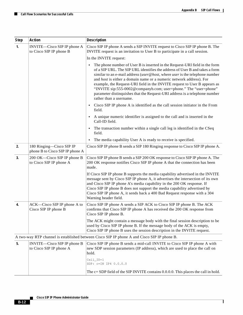
Appendix B SIP Call FlowsCall Flow Scenarios for Successful Calls
Step Action Description
1. INVITE—Cisco SIP IP phone A to Cisco SIP IP phone B
Cisco SIP IP phone A sends a SIP INVITE request to Cisco SIP IP phone B. The INVITE request is an invitation to User B to participate in a call session.
In the INVITE request:
• The phone number of User B is inserted in the Request-URI field in the form of a SIP URL. The SIP URL identifies the address of User B and takes a form similar to an e-mail address (user@host, where user is the telephone number and host is either a domain name or a numeric network address). For example, the Request-URI field in the INVITE request to User B appears as “INVITE sip:[email protected]; user=phone.” The “user=phone” parameter distinquishes that the Request-URI address is a telephone number rather than a username.
• Cisco SIP IP phone A is identified as the call session initiator in the From field.
• A unique numeric identifier is assigned to the call and is inserted in the Call-ID field.
• The transaction number within a single call leg is identified in the CSeq field.
• The media capability User A is ready to receive is specified.
2. 180 Ringing—Cisco SIP IP phone B to Cisco SIP IP phone A
Cisco SIP IP phone B sends a SIP 180 Ringing response to Cisco SIP IP phone A.
3. 200 OK—Cisco SIP IP phone B to Cisco SIP IP phone A
Cisco SIP IP phone B sends a SIP 200 OK response to Cisco SIP IP phone A. The 200 OK response notifies Cisco SIP IP phone A that the connection has been made.
If Cisco SIP IP phone B supports the media capability advertised in the INVITE message sent by Cisco SIP IP phone A, it advertises the intersection of its own and Cisco SIP IP phone A’s media capability in the 200 OK response. If Cisco SIP IP phone B does not support the media capability advertised by Cisco SIP IP phone A, it sends back a 400 Bad Request response with a 304 Warning header field.
4. ACK—Cisco SIP IP phone A to Cisco SIP IP phone B
Cisco SIP IP phone A sends a SIP ACK to Cisco SIP IP phone B. The ACK confirms that Cisco SIP IP phone A has received the 200 OK response from Cisco SIP IP phone B.
The ACK might contain a message body with the final session description to be used by Cisco SIP IP phone B. If the message body of the ACK is empty, Cisco SIP IP phone B uses the session description in the INVITE request.
A two-way RTP channel is established between Cisco SIP IP phone A and Cisco SIP IP phone B.
5. INVITE—Cisco SIP IP phone B to Cisco SIP IP phone A
Cisco SIP IP phone B sends a mid-call INVITE to Cisco SIP IP phone A with new SDP session parameters (IP address), which are used to place the call on hold.
Call_ID=1 SDP: c=IN IP4 0.0.0.0
The c= SDP field of the SIP INVITE contains 0.0.0.0. This places the call in hold.
B-12Cisco SIP IP Phone Administrator Guide
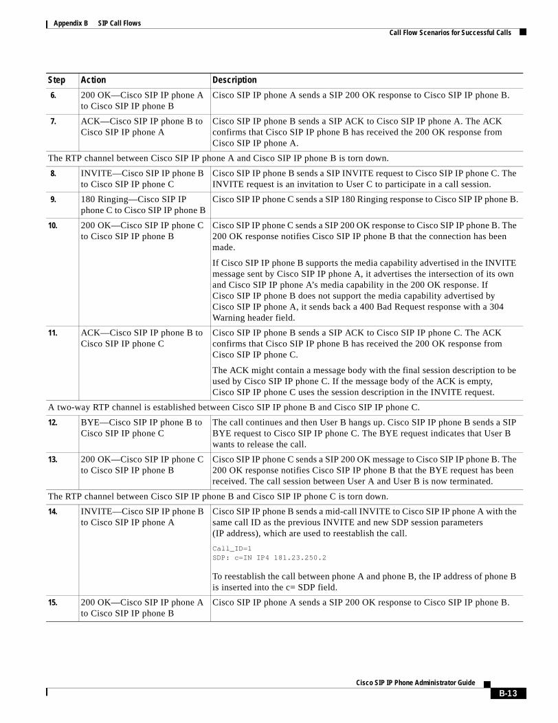
Appendix B SIP Call FlowsCall Flow Scenarios for Successful Calls
6. 200 OK—Cisco SIP IP phone A to Cisco SIP IP phone B
Cisco SIP IP phone A sends a SIP 200 OK response to Cisco SIP IP phone B.
7. ACK—Cisco SIP IP phone B to Cisco SIP IP phone A
Cisco SIP IP phone B sends a SIP ACK to Cisco SIP IP phone A. The ACK confirms that Cisco SIP IP phone B has received the 200 OK response from Cisco SIP IP phone A.
The RTP channel between Cisco SIP IP phone A and Cisco SIP IP phone B is torn down.
8. INVITE—Cisco SIP IP phone B to Cisco SIP IP phone C
Cisco SIP IP phone B sends a SIP INVITE request to Cisco SIP IP phone C. The INVITE request is an invitation to User C to participate in a call session.
9. 180 Ringing—Cisco SIP IP phone C to Cisco SIP IP phone B
Cisco SIP IP phone C sends a SIP 180 Ringing response to Cisco SIP IP phone B.
10. 200 OK—Cisco SIP IP phone C to Cisco SIP IP phone B
Cisco SIP IP phone C sends a SIP 200 OK response to Cisco SIP IP phone B. The 200 OK response notifies Cisco SIP IP phone B that the connection has been made.
If Cisco SIP IP phone B supports the media capability advertised in the INVITE message sent by Cisco SIP IP phone A, it advertises the intersection of its own and Cisco SIP IP phone A’s media capability in the 200 OK response. If Cisco SIP IP phone B does not support the media capability advertised by Cisco SIP IP phone A, it sends back a 400 Bad Request response with a 304 Warning header field.
11. ACK—Cisco SIP IP phone B to Cisco SIP IP phone C
Cisco SIP IP phone B sends a SIP ACK to Cisco SIP IP phone C. The ACK confirms that Cisco SIP IP phone B has received the 200 OK response from Cisco SIP IP phone C.
The ACK might contain a message body with the final session description to be used by Cisco SIP IP phone C. If the message body of the ACK is empty, Cisco SIP IP phone C uses the session description in the INVITE request.
A two-way RTP channel is established between Cisco SIP IP phone B and Cisco SIP IP phone C.
12. BYE—Cisco SIP IP phone B to Cisco SIP IP phone C
The call continues and then User B hangs up. Cisco SIP IP phone B sends a SIP BYE request to Cisco SIP IP phone C. The BYE request indicates that User B wants to release the call.
13. 200 OK—Cisco SIP IP phone C to Cisco SIP IP phone B
Cisco SIP IP phone C sends a SIP 200 OK message to Cisco SIP IP phone B. The 200 OK response notifies Cisco SIP IP phone B that the BYE request has been received. The call session between User A and User B is now terminated.
The RTP channel between Cisco SIP IP phone B and Cisco SIP IP phone C is torn down.
14. INVITE—Cisco SIP IP phone B to Cisco SIP IP phone A
Cisco SIP IP phone B sends a mid-call INVITE to Cisco SIP IP phone A with the same call ID as the previous INVITE and new SDP session parameters (IP address), which are used to reestablish the call.
Call_ID=1 SDP: c=IN IP4 181.23.250.2
To reestablish the call between phone A and phone B, the IP address of phone B is inserted into the c= SDP field.
15. 200 OK—Cisco SIP IP phone A to Cisco SIP IP phone B
Cisco SIP IP phone A sends a SIP 200 OK response to Cisco SIP IP phone B.
Step Action Description
B-13Cisco SIP IP Phone Administrator Guide
Appendix B SIP Call FlowsCall Flow Scenarios for Successful Calls
Call Waiting
Figure B-6 illustrates a successful call between Cisco SIP IP phones in which two parties are in a call, one of the participants receives a call from a third party, and then returns to the original call. In this call flow scenario, the end users are User A, User B, and User C. They are all using Cisco SIP IP phones, which are connected via an IP network.
The call flow scenario is as follows:
1. User A calls User B.
2. User B answers the call.
3. User C calls User B.
4. User B accepts the call from User C.
5. User B switches back to User A.
6. User B hangs up, ending the call with User A.
7. User B is notified of the remaining call with User C.
8. User B answers the notification and continues the call with User C.
16. ACK—Cisco SIP IP phone B to Cisco SIP IP phone A
Cisco SIP IP phone B sends a SIP ACK to Cisco SIP IP phone A. The ACK confirms that Cisco SIP IP phone B has received the 200 OK response from Cisco SIP IP phone A.
A two-way RTP channel is reestablished between Cisco SIP IP phone A and Cisco SIP IP phone B.
Step Action Description
B-14Cisco SIP IP Phone Administrator Guide
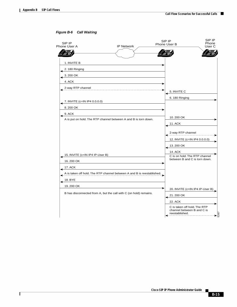
Appendix B SIP Call FlowsCall Flow Scenarios for Successful Calls
Figure B-6 Call Waiting
IP IP IP
2. 180 Ringing
3. 200 OK
2-way RTP channel
A is put on hold. The RTP channel between A and B is torn down.
B has disconnected from A, but the call with C (on hold) remains.
4. ACK
C is taken off hold. The RTPchannel between B and C isreestablished.
2-way RTP channel
C is on hold. The RTP channelbetween B and C is torn down.
A is taken off hold. The RTP channel between A and B is reestablished.
7. INVITE (c=IN IP4 0.0.0.0)
8. 200 OK
9. ACK
15. INVITE (c=IN IP4 IP-User B)
16. 200 OK
17. ACK
18. BYE
19. 200 OK
1. INVITE B
11. ACK
13. 200 OK
10. 200 OK
21. 200 OK
20. INVITE (c=IN IP4 IP-User B)
22. ACK
14. ACK
12. INVITE (c=IN IP4 0.0.0.0)
5. INVITE C
6. 180 Ringing
IP NetworkSIP IP
Phone User A
SIP IPPhone User B
SIP IPPhoneUser C
4146
7
B-15Cisco SIP IP Phone Administrator Guide
Appendix B SIP Call FlowsCall Flow Scenarios for Successful Calls
Step Action Description
1. INVITE—Cisco SIP IP phone A to Cisco SIP IP phone B
Cisco SIP IP phone A sends a SIP INVITE request to Cisco SIP IP phone B. The INVITE request is an invitation to User B to participate in a call session.
In the INVITE request:
• The phone number of User B is inserted in the Request-URI field in the form of a SIP URL. The SIP URL identifies the address of User B and takes a form similar to an e-mail address (user@host, where user is the telephone number and host is either a domain name or a numeric network address). For example, the Request-URI field in the INVITE request to User B appears as “INVITE sip:[email protected]; user=phone.” The “user=phone” parameter distinquishes that the Request-URI address is a telephone number rather than a username.
• Cisco SIP IP phone A is identified as the call session initiator in the From field.
• A unique numeric identifier is assigned to the call and is inserted in the Call-ID field.
• The transaction number within a single call leg is identified in the CSeq field.
• The media capability User A is ready to receive is specified.
2. 180 Ringing—Cisco SIP IP phone B to Cisco SIP IP phone A
Cisco SIP IP phone B sends a SIP 180 Ringing response to Cisco SIP IP phone A.
3. 200 OK—Cisco SIP IP phone B to Cisco SIP IP phone A
Cisco SIP IP phone B sends a SIP 200 OK response to Cisco SIP IP phone A. The 200 OK response notifies Cisco SIP IP phone A that the connection has been made.
If Cisco SIP IP phone B supports the media capability advertised in the INVITE message sent by Cisco SIP IP phone A, it advertises the intersection of its own and Cisco SIP IP phone A’s media capability in the 200 OK response. If Cisco SIP IP phone B does not support the media capability advertised by Cisco SIP IP phone A, it sends back a 400 Bad Request response with a 304 Warning header field.
4. ACK—Cisco SIP IP phone A to Cisco SIP IP phone B
Cisco SIP IP phone A sends a SIP ACK to Cisco SIP IP phone B. The ACK confirms that Cisco SIP IP phone A has received the 200 OK response from Cisco SIP IP phone B.
The ACK might contain a message body with the final session description to be used by Cisco SIP IP phone B. If the message body of the ACK is empty, Cisco SIP IP phone B uses the session description in the INVITE request.
A two-way RTP channel is established between Cisco SIP IP phone A and Cisco SIP IP phone B.
5. INVITE—Cisco SIP IP phone C to Cisco SIP IP phone B
Cisco SIP IP phone C sends a SIP INVITE request to Cisco SIP IP phone B. The INVITE request is an invitation to User B to participate in a call session.
6. 180 Ringing—Cisco SIP IP phone B to Cisco SIP IP phone C
Cisco SIP IP phone B sends a SIP 180 Ringing response to Cisco SIP IP phone C.
B-16Cisco SIP IP Phone Administrator Guide
Appendix B SIP Call FlowsCall Flow Scenarios for Successful Calls
7. INVITE—Cisco SIP IP phone B to Cisco SIP IP phone A
Cisco SIP IP phone B sends a mid-call INVITE to Cisco SIP IP phone A with new SDP session parameters (IP address), which are used to place the call on hold.
Call_ID=1 SDP: c=IN IP4 0.0.0.0
The c= SDP field of the SIP INVITE contains 0.0.0.0. This places the call in hold.
8. 200 OK—Cisco SIP IP phone A to Cisco SIP IP phone B
Cisco SIP IP phone A sends a SIP 200 OK response to Cisco SIP IP phone B.
9. ACK—Cisco SIP IP phone B to Cisco SIP IP phone A
Cisco SIP IP phone B sends a SIP ACK to Cisco SIP IP phone A. The ACK confirms that Cisco SIP IP phone B has received the 200 OK response from Cisco SIP IP phone A.
The RTP channel between Cisco SIP IP phone A and Cisco SIP IP phone B is torn down.
10. 200 OK—Cisco SIP IP phone B to Cisco SIP IP phone C
Cisco SIP IP phone B sends a SIP 200 OK response to Cisco SIP IP phone C. The 200 OK response notifies Cisco SIP IP phone C that the connection has been made.
11. ACK—Cisco SIP IP phone C to Cisco SIP IP phone B
Cisco SIP IP phone C sends a SIP ACK to Cisco SIP IP phone B. The ACK confirms that Cisco SIP IP phone C has received the 200 OK response from Cisco SIP IP phone B.
The ACK might contain a message body with the final session description to be used by Cisco SIP IP phone B. If the message body of the ACK is empty, Cisco SIP IP phone B uses the session description in the INVITE request.
A two-way RTP channel is established between Cisco SIP IP phone B and Cisco SIP IP phone C.
12. INVITE—Cisco SIP IP phone B to Cisco SIP IP phone C
Cisco SIP IP phone B sends a mid-call INVITE to Cisco SIP IP phone C with new SDP session parameters (IP address), which are used to place the call on hold.
Call_ID=2 SDP: c=IN IP4 0.0.0.0
To establish the call between phone B and phone C, the IP address of phone B is inserted into the c= SDP field.
13. 200 OK—Cisco SIP IP phone C to Cisco SIP IP phone B
Cisco SIP IP phone C sends a SIP 200 OK response to Cisco SIP IP phone B.
14. ACK—Cisco SIP IP phone B to Cisco SIP IP phone C
Cisco SIP IP phone B sends a SIP ACK to Cisco SIP IP phone C. The ACK confirms that Cisco SIP IP phone B has received the 200 OK response from Cisco SIP IP phone C.
The RTP channel between Cisco SIP IP phone B and Cisco SIP IP phone C is torn down.
15. INVITE—Cisco SIP IP phone B to Cisco SIP IP phone A
Cisco SIP IP phone B sends a mid-call INVITE to Cisco SIP IP phone A with the same call ID as the previous INVITE (sent to Cisco SIP IP phone A) and new SDP session parameters (IP address), which are used to reestablish the call.
Call_ID=1 SDP: c=IN IP4 10.10.10.0
16. 200 OK—Cisco SIP IP phone A to Cisco SIP IP phone B
Cisco SIP IP phone A sends a SIP 200 OK response to Cisco SIP IP phone B.
Step Action Description
B-17Cisco SIP IP Phone Administrator Guide
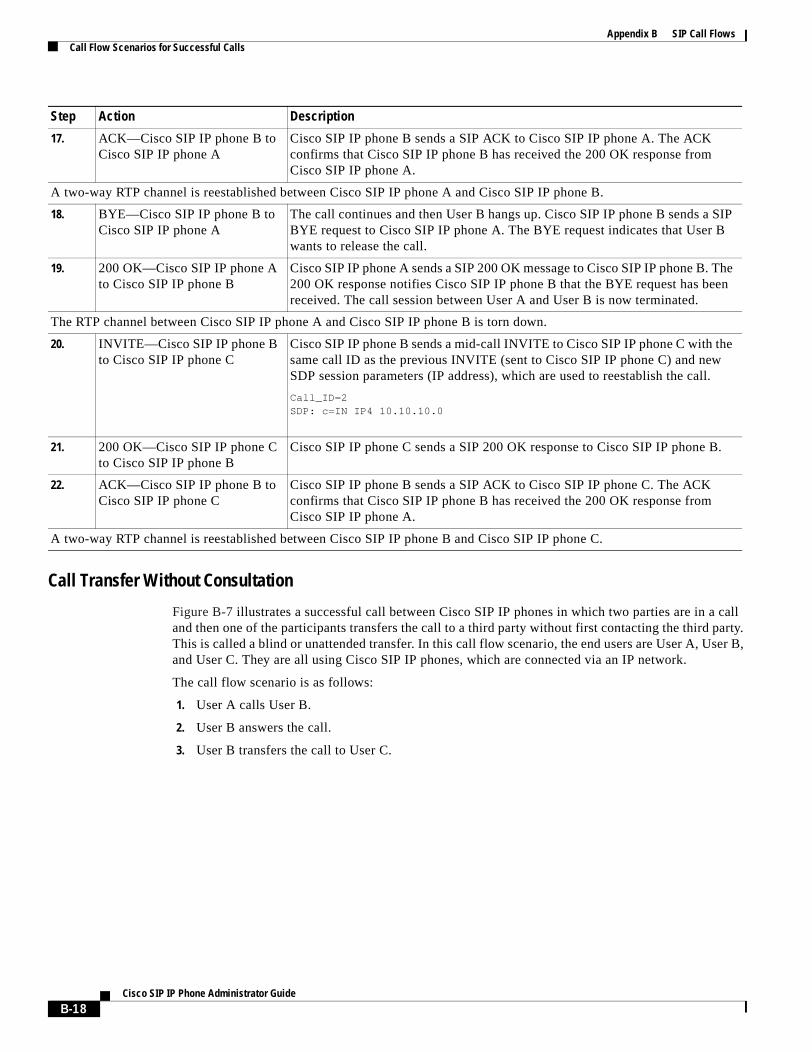
Appendix B SIP Call FlowsCall Flow Scenarios for Successful Calls
Call Transfer Without Consultation
Figure B-7 illustrates a successful call between Cisco SIP IP phones in which two parties are in a call and then one of the participants transfers the call to a third party without first contacting the third party. This is called a blind or unattended transfer. In this call flow scenario, the end users are User A, User B, and User C. They are all using Cisco SIP IP phones, which are connected via an IP network.
The call flow scenario is as follows:
1. User A calls User B.
2. User B answers the call.
3. User B transfers the call to User C.
17. ACK—Cisco SIP IP phone B to Cisco SIP IP phone A
Cisco SIP IP phone B sends a SIP ACK to Cisco SIP IP phone A. The ACK confirms that Cisco SIP IP phone B has received the 200 OK response from Cisco SIP IP phone A.
A two-way RTP channel is reestablished between Cisco SIP IP phone A and Cisco SIP IP phone B.
18. BYE—Cisco SIP IP phone B to Cisco SIP IP phone A
The call continues and then User B hangs up. Cisco SIP IP phone B sends a SIP BYE request to Cisco SIP IP phone A. The BYE request indicates that User B wants to release the call.
19. 200 OK—Cisco SIP IP phone A to Cisco SIP IP phone B
Cisco SIP IP phone A sends a SIP 200 OK message to Cisco SIP IP phone B. The 200 OK response notifies Cisco SIP IP phone B that the BYE request has been received. The call session between User A and User B is now terminated.
The RTP channel between Cisco SIP IP phone A and Cisco SIP IP phone B is torn down.
20. INVITE—Cisco SIP IP phone B to Cisco SIP IP phone C
Cisco SIP IP phone B sends a mid-call INVITE to Cisco SIP IP phone C with the same call ID as the previous INVITE (sent to Cisco SIP IP phone C) and new SDP session parameters (IP address), which are used to reestablish the call.
Call_ID=2 SDP: c=IN IP4 10.10.10.0
21. 200 OK—Cisco SIP IP phone C to Cisco SIP IP phone B
Cisco SIP IP phone C sends a SIP 200 OK response to Cisco SIP IP phone B.
22. ACK—Cisco SIP IP phone B to Cisco SIP IP phone C
Cisco SIP IP phone B sends a SIP ACK to Cisco SIP IP phone C. The ACK confirms that Cisco SIP IP phone B has received the 200 OK response from Cisco SIP IP phone A.
A two-way RTP channel is reestablished between Cisco SIP IP phone B and Cisco SIP IP phone C.
Step Action Description
B-18Cisco SIP IP Phone Administrator Guide
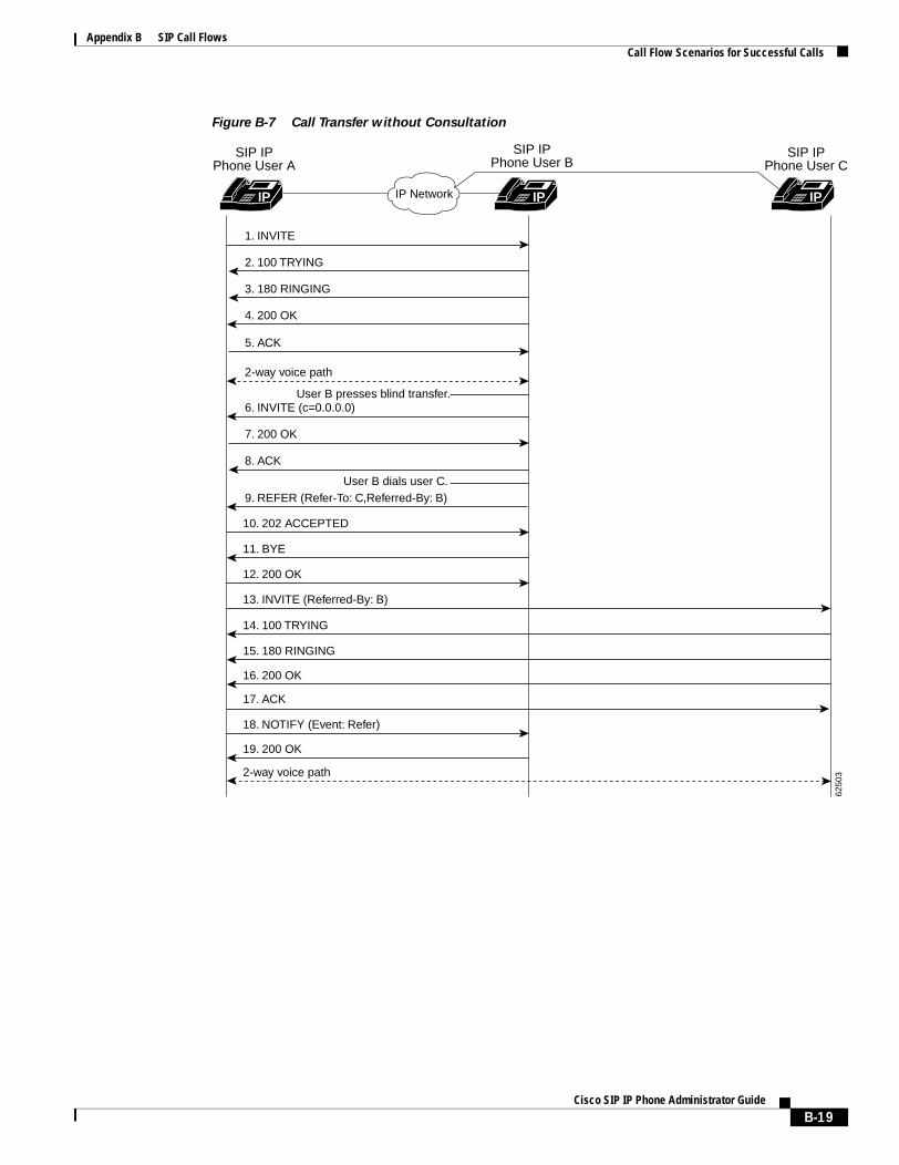
Appendix B SIP Call FlowsCall Flow Scenarios for Successful Calls
Figure B-7 Call Transfer without Consultation
IP Network
SIP IPPhone User B
IP IP
2. 100 TRYING
3. 180 RINGING
4. 200 OK
11. BYE
12. 200 OK
13. INVITE (Referred-By: B)
14. 100 TRYING
15. 180 RINGING
16. 200 OK
17. ACK
18. NOTIFY (Event: Refer)
19. 200 OK
2-way voice path
5. ACK
2-way voice path
User B presses blind transfer.6. INVITE (c=0.0.0.0)
7. 200 OK
8. ACK
9. REFER (Refer-To: C,Referred-By: B)
10. 202 ACCEPTED
1. INVITE
SIP IPPhone User A
SIP IPPhone User C
IP
6250
3
User B dials user C.
B-19Cisco SIP IP Phone Administrator Guide
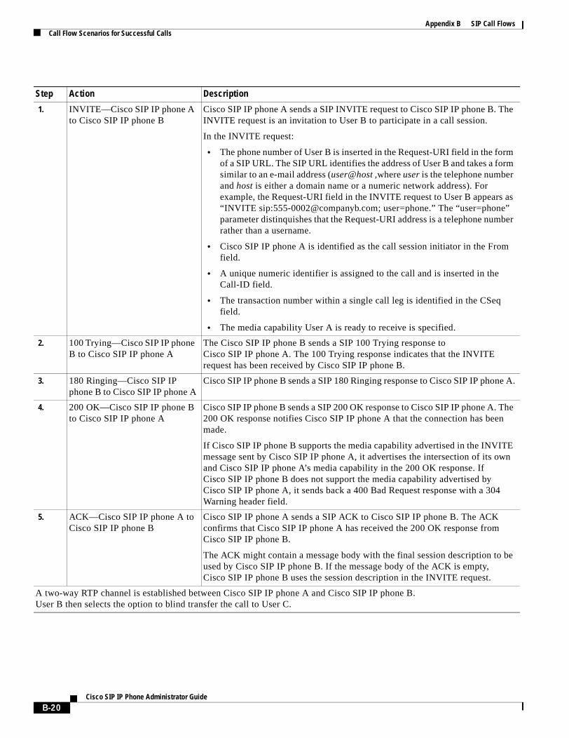
Appendix B SIP Call FlowsCall Flow Scenarios for Successful Calls
Step Action Description
1. INVITE—Cisco SIP IP phone A to Cisco SIP IP phone B
Cisco SIP IP phone A sends a SIP INVITE request to Cisco SIP IP phone B. The INVITE request is an invitation to User B to participate in a call session.
In the INVITE request:
• The phone number of User B is inserted in the Request-URI field in the form of a SIP URL. The SIP URL identifies the address of User B and takes a form similar to an e-mail address (user@host ,where user is the telephone number and host is either a domain name or a numeric network address). For example, the Request-URI field in the INVITE request to User B appears as “INVITE sip:[email protected]; user=phone.” The “user=phone” parameter distinquishes that the Request-URI address is a telephone number rather than a username.
• Cisco SIP IP phone A is identified as the call session initiator in the From field.
• A unique numeric identifier is assigned to the call and is inserted in the Call-ID field.
• The transaction number within a single call leg is identified in the CSeq field.
• The media capability User A is ready to receive is specified.
2. 100 Trying—Cisco SIP IP phone B to Cisco SIP IP phone A
The Cisco SIP IP phone B sends a SIP 100 Trying response to Cisco SIP IP phone A. The 100 Trying response indicates that the INVITE request has been received by Cisco SIP IP phone B.
3. 180 Ringing—Cisco SIP IP phone B to Cisco SIP IP phone A
Cisco SIP IP phone B sends a SIP 180 Ringing response to Cisco SIP IP phone A.
4. 200 OK—Cisco SIP IP phone B to Cisco SIP IP phone A
Cisco SIP IP phone B sends a SIP 200 OK response to Cisco SIP IP phone A. The 200 OK response notifies Cisco SIP IP phone A that the connection has been made.
If Cisco SIP IP phone B supports the media capability advertised in the INVITE message sent by Cisco SIP IP phone A, it advertises the intersection of its own and Cisco SIP IP phone A’s media capability in the 200 OK response. If Cisco SIP IP phone B does not support the media capability advertised by Cisco SIP IP phone A, it sends back a 400 Bad Request response with a 304 Warning header field.
5. ACK—Cisco SIP IP phone A to Cisco SIP IP phone B
Cisco SIP IP phone A sends a SIP ACK to Cisco SIP IP phone B. The ACK confirms that Cisco SIP IP phone A has received the 200 OK response from Cisco SIP IP phone B.
The ACK might contain a message body with the final session description to be used by Cisco SIP IP phone B. If the message body of the ACK is empty, Cisco SIP IP phone B uses the session description in the INVITE request.
A two-way RTP channel is established between Cisco SIP IP phone A and Cisco SIP IP phone B.User B then selects the option to blind transfer the call to User C.
B-20Cisco SIP IP Phone Administrator Guide
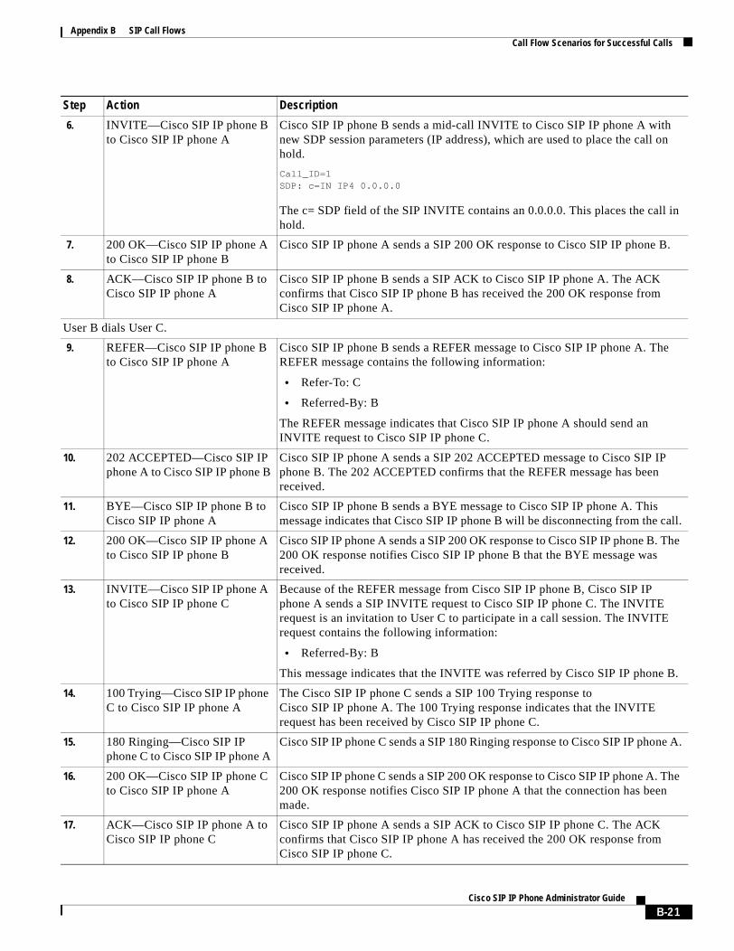
Appendix B SIP Call FlowsCall Flow Scenarios for Successful Calls
6. INVITE—Cisco SIP IP phone B to Cisco SIP IP phone A
Cisco SIP IP phone B sends a mid-call INVITE to Cisco SIP IP phone A with new SDP session parameters (IP address), which are used to place the call on hold.
Call_ID=1 SDP: c=IN IP4 0.0.0.0
The c= SDP field of the SIP INVITE contains an 0.0.0.0. This places the call in hold.
7. 200 OK—Cisco SIP IP phone A to Cisco SIP IP phone B
Cisco SIP IP phone A sends a SIP 200 OK response to Cisco SIP IP phone B.
8. ACK—Cisco SIP IP phone B to Cisco SIP IP phone A
Cisco SIP IP phone B sends a SIP ACK to Cisco SIP IP phone A. The ACK confirms that Cisco SIP IP phone B has received the 200 OK response from Cisco SIP IP phone A.
User B dials User C.
9. REFER—Cisco SIP IP phone B to Cisco SIP IP phone A
Cisco SIP IP phone B sends a REFER message to Cisco SIP IP phone A. The REFER message contains the following information:
• Refer-To: C
• Referred-By: B
The REFER message indicates that Cisco SIP IP phone A should send an INVITE request to Cisco SIP IP phone C.
10. 202 ACCEPTED—Cisco SIP IP phone A to Cisco SIP IP phone B
Cisco SIP IP phone A sends a SIP 202 ACCEPTED message to Cisco SIP IP phone B. The 202 ACCEPTED confirms that the REFER message has been received.
11. BYE—Cisco SIP IP phone B to Cisco SIP IP phone A
Cisco SIP IP phone B sends a BYE message to Cisco SIP IP phone A. This message indicates that Cisco SIP IP phone B will be disconnecting from the call.
12. 200 OK—Cisco SIP IP phone A to Cisco SIP IP phone B
Cisco SIP IP phone A sends a SIP 200 OK response to Cisco SIP IP phone B. The 200 OK response notifies Cisco SIP IP phone B that the BYE message was received.
13. INVITE—Cisco SIP IP phone A to Cisco SIP IP phone C
Because of the REFER message from Cisco SIP IP phone B, Cisco SIP IP phone A sends a SIP INVITE request to Cisco SIP IP phone C. The INVITE request is an invitation to User C to participate in a call session. The INVITE request contains the following information:
• Referred-By: B
This message indicates that the INVITE was referred by Cisco SIP IP phone B.
14. 100 Trying—Cisco SIP IP phone C to Cisco SIP IP phone A
The Cisco SIP IP phone C sends a SIP 100 Trying response to Cisco SIP IP phone A. The 100 Trying response indicates that the INVITE request has been received by Cisco SIP IP phone C.
15. 180 Ringing—Cisco SIP IP phone C to Cisco SIP IP phone A
Cisco SIP IP phone C sends a SIP 180 Ringing response to Cisco SIP IP phone A.
16. 200 OK—Cisco SIP IP phone C to Cisco SIP IP phone A
Cisco SIP IP phone C sends a SIP 200 OK response to Cisco SIP IP phone A. The 200 OK response notifies Cisco SIP IP phone A that the connection has been made.
17. ACK—Cisco SIP IP phone A to Cisco SIP IP phone C
Cisco SIP IP phone A sends a SIP ACK to Cisco SIP IP phone C. The ACK confirms that Cisco SIP IP phone A has received the 200 OK response from Cisco SIP IP phone C.
Step Action Description
B-21Cisco SIP IP Phone Administrator Guide
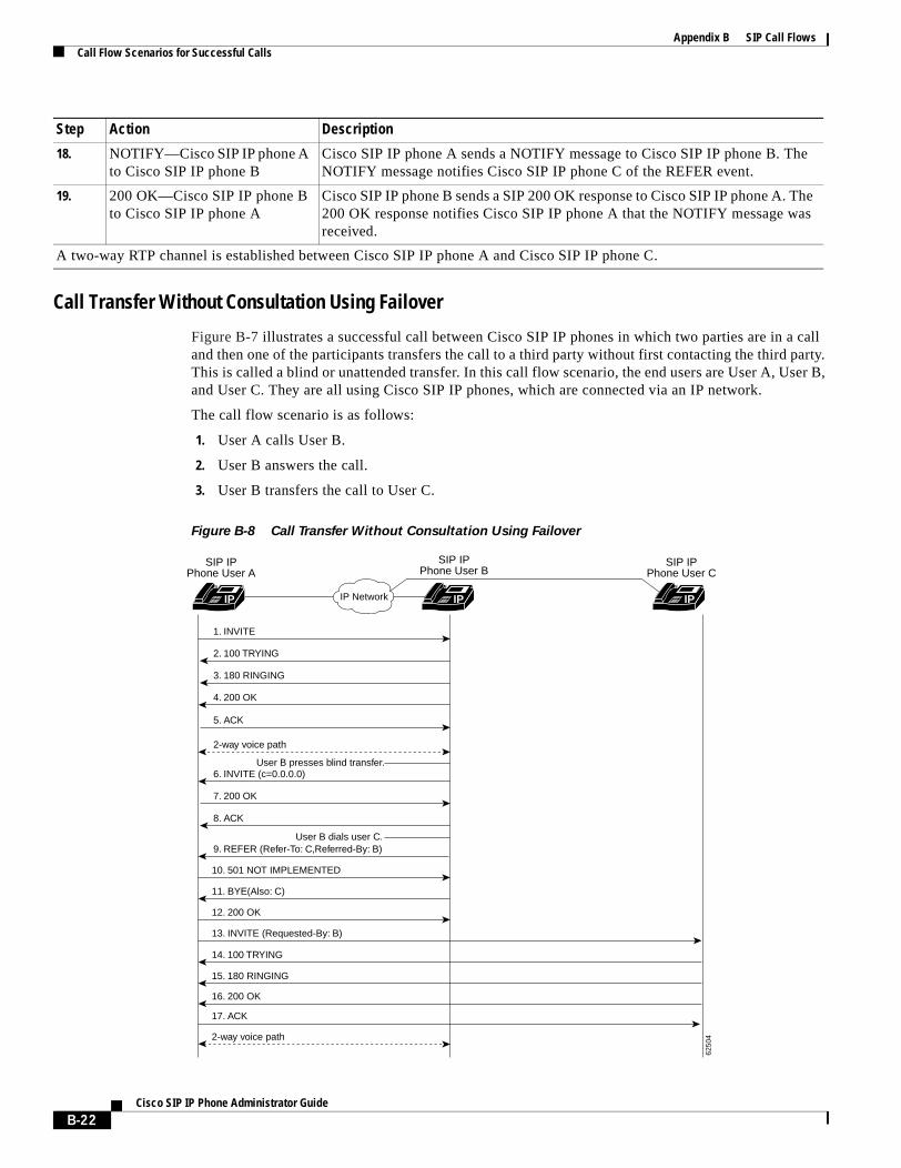
Appendix B SIP Call FlowsCall Flow Scenarios for Successful Calls
Call Transfer Without Consultation Using Failover
Figure B-7 illustrates a successful call between Cisco SIP IP phones in which two parties are in a call and then one of the participants transfers the call to a third party without first contacting the third party. This is called a blind or unattended transfer. In this call flow scenario, the end users are User A, User B, and User C. They are all using Cisco SIP IP phones, which are connected via an IP network.
The call flow scenario is as follows:
1. User A calls User B.
2. User B answers the call.
3. User B transfers the call to User C.
Figure B-8 Call Transfer Without Consultation Using Failover
18. NOTIFY—Cisco SIP IP phone A to Cisco SIP IP phone B
Cisco SIP IP phone A sends a NOTIFY message to Cisco SIP IP phone B. The NOTIFY message notifies Cisco SIP IP phone C of the REFER event.
19. 200 OK—Cisco SIP IP phone B to Cisco SIP IP phone A
Cisco SIP IP phone B sends a SIP 200 OK response to Cisco SIP IP phone A. The 200 OK response notifies Cisco SIP IP phone A that the NOTIFY message was received.
A two-way RTP channel is established between Cisco SIP IP phone A and Cisco SIP IP phone C.
Step Action Description
IP Network
SIP IPPhone User B
IP IP
2. 100 TRYING
3. 180 RINGING
4. 200 OK
11. BYE(Also: C)
12. 200 OK
13. INVITE (Requested-By: B)
14. 100 TRYING
15. 180 RINGING
16. 200 OK
17. ACK
2-way voice path
5. ACK
2-way voice path
User B presses blind transfer.6. INVITE (c=0.0.0.0)
7. 200 OK
8. ACK
9. REFER (Refer-To: C,Referred-By: B)
10. 501 NOT IMPLEMENTED
1. INVITE
SIP IPPhone User A
SIP IPPhone User C
IP
6250
4
User B dials user C.
B-22Cisco SIP IP Phone Administrator Guide
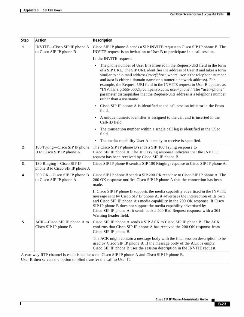
Appendix B SIP Call FlowsCall Flow Scenarios for Successful Calls
Step Action Description
1. INVITE—Cisco SIP IP phone A to Cisco SIP IP phone B
Cisco SIP IP phone A sends a SIP INVITE request to Cisco SIP IP phone B. The INVITE request is an invitation to User B to participate in a call session.
In the INVITE request:
• The phone number of User B is inserted in the Request-URI field in the form of a SIP URL. The SIP URL identifies the address of User B and takes a form similar to an e-mail address (user@host ,where user is the telephone number and host is either a domain name or a numeric network address). For example, the Request-URI field in the INVITE request to User B appears as “INVITE sip:[email protected]; user=phone.” The “user=phone” parameter distinquishes that the Request-URI address is a telephone number rather than a username.
• Cisco SIP IP phone A is identified as the call session initiator in the From field.
• A unique numeric identifier is assigned to the call and is inserted in the Call-ID field.
• The transaction number within a single call leg is identified in the CSeq field.
• The media capability User A is ready to receive is specified.
2. 100 Trying—Cisco SIP IP phone B to Cisco SIP IP phone A
The Cisco SIP IP phone B sends a SIP 100 Trying response to Cisco SIP IP phone A. The 100 Trying response indicates that the INVITE request has been received by Cisco SIP IP phone B.
3. 180 Ringing—Cisco SIP IP phone B to Cisco SIP IP phone A
Cisco SIP IP phone B sends a SIP 180 Ringing response to Cisco SIP IP phone A.
4. 200 OK—Cisco SIP IP phone B to Cisco SIP IP phone A
Cisco SIP IP phone B sends a SIP 200 OK response to Cisco SIP IP phone A. The 200 OK response notifies Cisco SIP IP phone A that the connection has been made.
If Cisco SIP IP phone B supports the media capability advertised in the INVITE message sent by Cisco SIP IP phone A, it advertises the intersection of its own and Cisco SIP IP phone A’s media capability in the 200 OK response. If Cisco SIP IP phone B does not support the media capability advertised by Cisco SIP IP phone A, it sends back a 400 Bad Request response with a 304 Warning header field.
5. ACK—Cisco SIP IP phone A to Cisco SIP IP phone B
Cisco SIP IP phone A sends a SIP ACK to Cisco SIP IP phone B. The ACK confirms that Cisco SIP IP phone A has received the 200 OK response from Cisco SIP IP phone B.
The ACK might contain a message body with the final session description to be used by Cisco SIP IP phone B. If the message body of the ACK is empty, Cisco SIP IP phone B uses the session description in the INVITE request.
A two-way RTP channel is established between Cisco SIP IP phone A and Cisco SIP IP phone B.User B then selects the option to blind transfer the call to User C.
B-23Cisco SIP IP Phone Administrator Guide
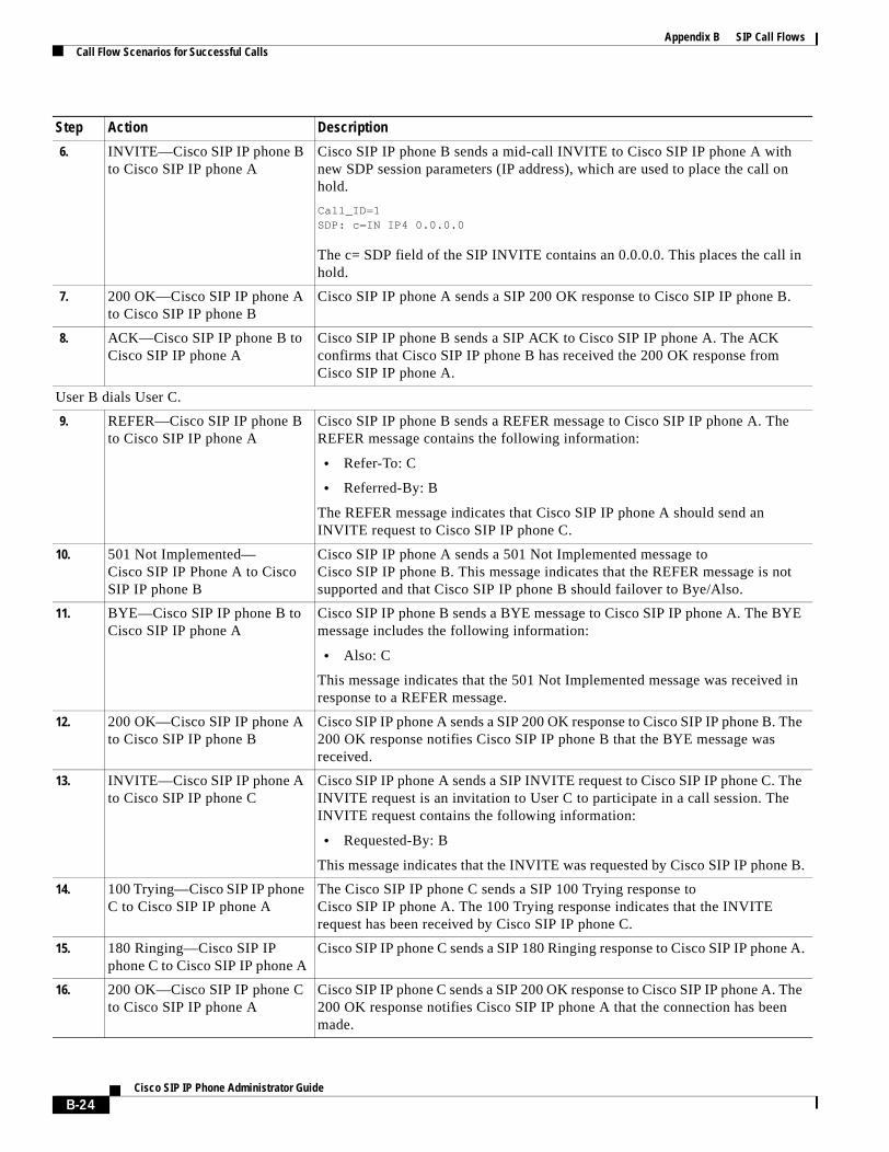
Appendix B SIP Call FlowsCall Flow Scenarios for Successful Calls
6. INVITE—Cisco SIP IP phone B to Cisco SIP IP phone A
Cisco SIP IP phone B sends a mid-call INVITE to Cisco SIP IP phone A with new SDP session parameters (IP address), which are used to place the call on hold.
Call_ID=1 SDP: c=IN IP4 0.0.0.0
The c= SDP field of the SIP INVITE contains an 0.0.0.0. This places the call in hold.
7. 200 OK—Cisco SIP IP phone A to Cisco SIP IP phone B
Cisco SIP IP phone A sends a SIP 200 OK response to Cisco SIP IP phone B.
8. ACK—Cisco SIP IP phone B to Cisco SIP IP phone A
Cisco SIP IP phone B sends a SIP ACK to Cisco SIP IP phone A. The ACK confirms that Cisco SIP IP phone B has received the 200 OK response from Cisco SIP IP phone A.
User B dials User C.
9. REFER—Cisco SIP IP phone B to Cisco SIP IP phone A
Cisco SIP IP phone B sends a REFER message to Cisco SIP IP phone A. The REFER message contains the following information:
• Refer-To: C
• Referred-By: B
The REFER message indicates that Cisco SIP IP phone A should send an INVITE request to Cisco SIP IP phone C.
10. 501 Not Implemented—Cisco SIP IP Phone A to Cisco SIP IP phone B
Cisco SIP IP phone A sends a 501 Not Implemented message to Cisco SIP IP phone B. This message indicates that the REFER message is not supported and that Cisco SIP IP phone B should failover to Bye/Also.
11. BYE—Cisco SIP IP phone B to Cisco SIP IP phone A
Cisco SIP IP phone B sends a BYE message to Cisco SIP IP phone A. The BYE message includes the following information:
• Also: C
This message indicates that the 501 Not Implemented message was received in response to a REFER message.
12. 200 OK—Cisco SIP IP phone A to Cisco SIP IP phone B
Cisco SIP IP phone A sends a SIP 200 OK response to Cisco SIP IP phone B. The 200 OK response notifies Cisco SIP IP phone B that the BYE message was received.
13. INVITE—Cisco SIP IP phone A to Cisco SIP IP phone C
Cisco SIP IP phone A sends a SIP INVITE request to Cisco SIP IP phone C. The INVITE request is an invitation to User C to participate in a call session. The INVITE request contains the following information:
• Requested-By: B
This message indicates that the INVITE was requested by Cisco SIP IP phone B.
14. 100 Trying—Cisco SIP IP phone C to Cisco SIP IP phone A
The Cisco SIP IP phone C sends a SIP 100 Trying response to Cisco SIP IP phone A. The 100 Trying response indicates that the INVITE request has been received by Cisco SIP IP phone C.
15. 180 Ringing—Cisco SIP IP phone C to Cisco SIP IP phone A
Cisco SIP IP phone C sends a SIP 180 Ringing response to Cisco SIP IP phone A.
16. 200 OK—Cisco SIP IP phone C to Cisco SIP IP phone A
Cisco SIP IP phone C sends a SIP 200 OK response to Cisco SIP IP phone A. The 200 OK response notifies Cisco SIP IP phone A that the connection has been made.
Step Action Description
B-24Cisco SIP IP Phone Administrator Guide
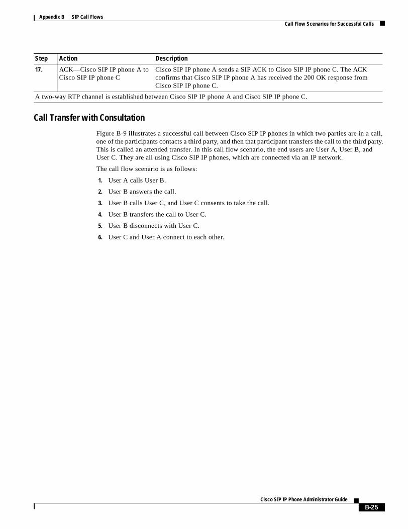
Appendix B SIP Call FlowsCall Flow Scenarios for Successful Calls
Call Transfer with Consultation
Figure B-9 illustrates a successful call between Cisco SIP IP phones in which two parties are in a call, one of the participants contacts a third party, and then that participant transfers the call to the third party. This is called an attended transfer. In this call flow scenario, the end users are User A, User B, and User C. They are all using Cisco SIP IP phones, which are connected via an IP network.
The call flow scenario is as follows:
1. User A calls User B.
2. User B answers the call.
3. User B calls User C, and User C consents to take the call.
4. User B transfers the call to User C.
5. User B disconnects with User C.
6. User C and User A connect to each other.
17. ACK—Cisco SIP IP phone A to Cisco SIP IP phone C
Cisco SIP IP phone A sends a SIP ACK to Cisco SIP IP phone C. The ACK confirms that Cisco SIP IP phone A has received the 200 OK response from Cisco SIP IP phone C.
A two-way RTP channel is established between Cisco SIP IP phone A and Cisco SIP IP phone C.
Step Action Description
B-25Cisco SIP IP Phone Administrator Guide
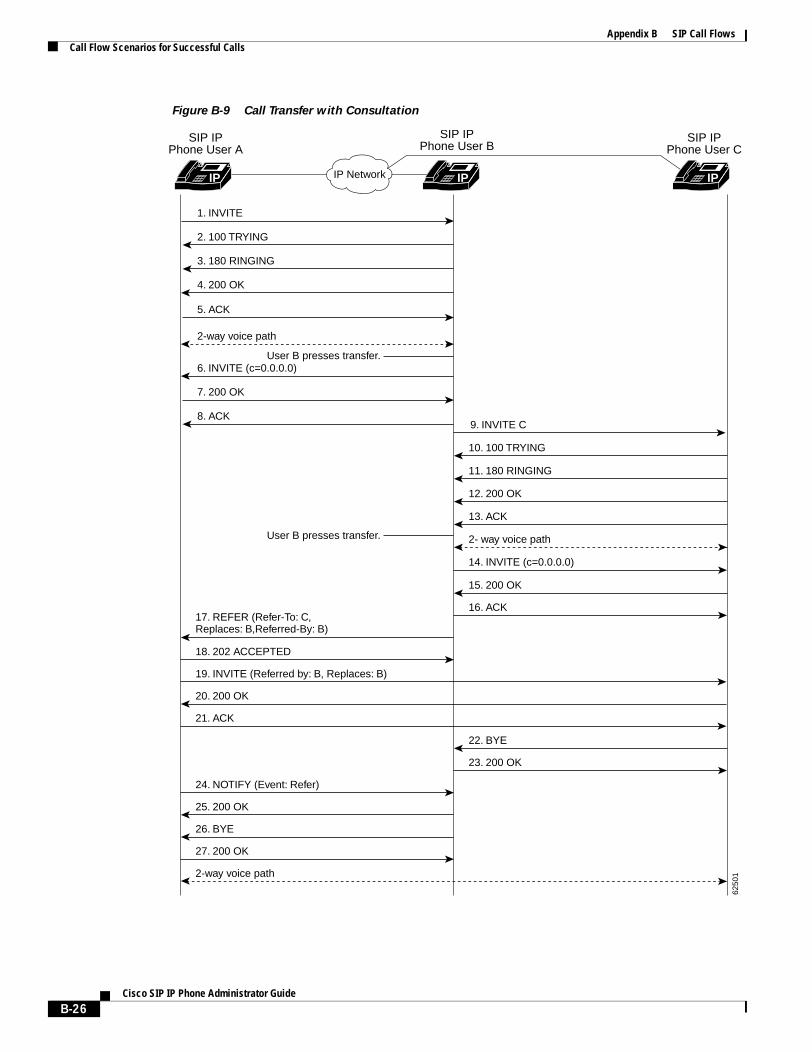
Appendix B SIP Call FlowsCall Flow Scenarios for Successful Calls
Figure B-9 Call Transfer with Consultation
IP Network
SIP IPPhone User B
IP IP
2. 100 TRYING
3. 180 RINGING
4. 200 OK
11. 180 RINGING
12. 200 OK
13. ACK
2- way voice path
14. INVITE (c=0.0.0.0)
15. 200 OK
16. ACK17. REFER (Refer-To: C,Replaces: B,Referred-By: B)
18. 202 ACCEPTED
19. INVITE (Referred by: B, Replaces: B)
20. 200 OK
21. ACK
22. BYE
23. 200 OK
24. NOTIFY (Event: Refer)
25. 200 OK
26. BYE
27. 200 OK
2-way voice path
5. ACK
2-way voice path
User B presses transfer.6. INVITE (c=0.0.0.0)
7. 200 OK
8. ACK9. INVITE C
10. 100 TRYING
1. INVITE
SIP IPPhone User A
SIP IPPhone User C
IP
6250
1
User B presses transfer.
B-26Cisco SIP IP Phone Administrator Guide
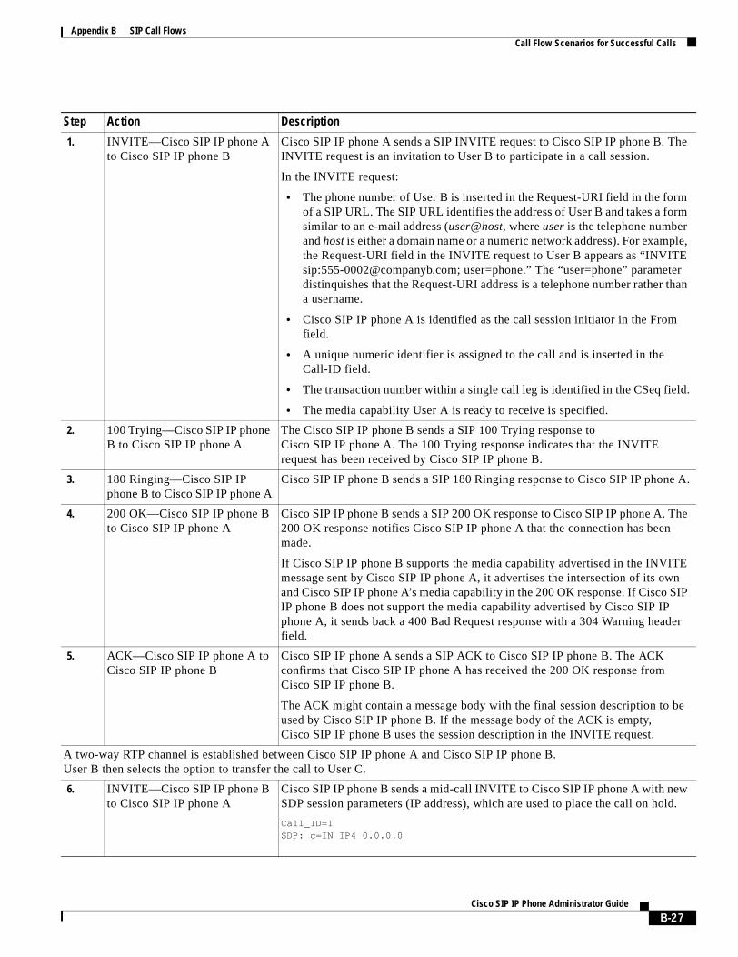
Appendix B SIP Call FlowsCall Flow Scenarios for Successful Calls
Step Action Description
1. INVITE—Cisco SIP IP phone A to Cisco SIP IP phone B
Cisco SIP IP phone A sends a SIP INVITE request to Cisco SIP IP phone B. The INVITE request is an invitation to User B to participate in a call session.
In the INVITE request:
• The phone number of User B is inserted in the Request-URI field in the form of a SIP URL. The SIP URL identifies the address of User B and takes a form similar to an e-mail address (user@host, where user is the telephone number and host is either a domain name or a numeric network address). For example, the Request-URI field in the INVITE request to User B appears as “INVITE sip:[email protected]; user=phone.” The “user=phone” parameter distinquishes that the Request-URI address is a telephone number rather than a username.
• Cisco SIP IP phone A is identified as the call session initiator in the From field.
• A unique numeric identifier is assigned to the call and is inserted in the Call-ID field.
• The transaction number within a single call leg is identified in the CSeq field.
• The media capability User A is ready to receive is specified.
2. 100 Trying—Cisco SIP IP phone B to Cisco SIP IP phone A
The Cisco SIP IP phone B sends a SIP 100 Trying response to Cisco SIP IP phone A. The 100 Trying response indicates that the INVITE request has been received by Cisco SIP IP phone B.
3. 180 Ringing—Cisco SIP IP phone B to Cisco SIP IP phone A
Cisco SIP IP phone B sends a SIP 180 Ringing response to Cisco SIP IP phone A.
4. 200 OK—Cisco SIP IP phone B to Cisco SIP IP phone A
Cisco SIP IP phone B sends a SIP 200 OK response to Cisco SIP IP phone A. The 200 OK response notifies Cisco SIP IP phone A that the connection has been made.
If Cisco SIP IP phone B supports the media capability advertised in the INVITE message sent by Cisco SIP IP phone A, it advertises the intersection of its own and Cisco SIP IP phone A’s media capability in the 200 OK response. If Cisco SIP IP phone B does not support the media capability advertised by Cisco SIP IP phone A, it sends back a 400 Bad Request response with a 304 Warning header field.
5. ACK—Cisco SIP IP phone A to Cisco SIP IP phone B
Cisco SIP IP phone A sends a SIP ACK to Cisco SIP IP phone B. The ACK confirms that Cisco SIP IP phone A has received the 200 OK response from Cisco SIP IP phone B.
The ACK might contain a message body with the final session description to be used by Cisco SIP IP phone B. If the message body of the ACK is empty, Cisco SIP IP phone B uses the session description in the INVITE request.
A two-way RTP channel is established between Cisco SIP IP phone A and Cisco SIP IP phone B.User B then selects the option to transfer the call to User C.
6. INVITE—Cisco SIP IP phone B to Cisco SIP IP phone A
Cisco SIP IP phone B sends a mid-call INVITE to Cisco SIP IP phone A with new SDP session parameters (IP address), which are used to place the call on hold.
Call_ID=1 SDP: c=IN IP4 0.0.0.0
B-27Cisco SIP IP Phone Administrator Guide
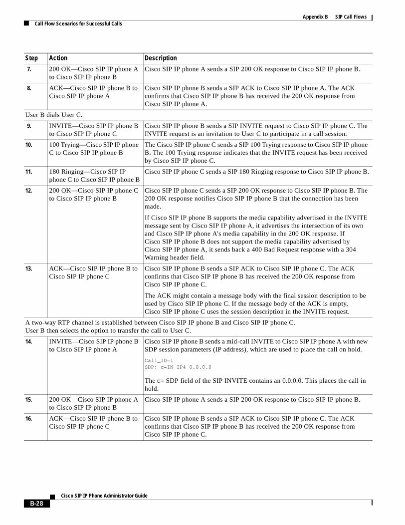
Appendix B SIP Call FlowsCall Flow Scenarios for Successful Calls
7. 200 OK—Cisco SIP IP phone A to Cisco SIP IP phone B
Cisco SIP IP phone A sends a SIP 200 OK response to Cisco SIP IP phone B.
8. ACK—Cisco SIP IP phone B to Cisco SIP IP phone A
Cisco SIP IP phone B sends a SIP ACK to Cisco SIP IP phone A. The ACK confirms that Cisco SIP IP phone B has received the 200 OK response from Cisco SIP IP phone A.
User B dials User C.
9. INVITE—Cisco SIP IP phone B to Cisco SIP IP phone C
Cisco SIP IP phone B sends a SIP INVITE request to Cisco SIP IP phone C. The INVITE request is an invitation to User C to participate in a call session.
10. 100 Trying—Cisco SIP IP phone C to Cisco SIP IP phone B
The Cisco SIP IP phone C sends a SIP 100 Trying response to Cisco SIP IP phone B. The 100 Trying response indicates that the INVITE request has been received by Cisco SIP IP phone C.
11. 180 Ringing—Cisco SIP IP phone C to Cisco SIP IP phone B
Cisco SIP IP phone C sends a SIP 180 Ringing response to Cisco SIP IP phone B.
12. 200 OK—Cisco SIP IP phone C to Cisco SIP IP phone B
Cisco SIP IP phone C sends a SIP 200 OK response to Cisco SIP IP phone B. The 200 OK response notifies Cisco SIP IP phone B that the connection has been made.
If Cisco SIP IP phone B supports the media capability advertised in the INVITE message sent by Cisco SIP IP phone A, it advertises the intersection of its own and Cisco SIP IP phone A’s media capability in the 200 OK response. If Cisco SIP IP phone B does not support the media capability advertised by Cisco SIP IP phone A, it sends back a 400 Bad Request response with a 304 Warning header field.
13. ACK—Cisco SIP IP phone B to Cisco SIP IP phone C
Cisco SIP IP phone B sends a SIP ACK to Cisco SIP IP phone C. The ACK confirms that Cisco SIP IP phone B has received the 200 OK response from Cisco SIP IP phone C.
The ACK might contain a message body with the final session description to be used by Cisco SIP IP phone C. If the message body of the ACK is empty, Cisco SIP IP phone C uses the session description in the INVITE request.
A two-way RTP channel is established between Cisco SIP IP phone B and Cisco SIP IP phone C.User B then selects the option to transfer the call to User C.
14. INVITE—Cisco SIP IP phone B to Cisco SIP IP phone A
Cisco SIP IP phone B sends a mid-call INVITE to Cisco SIP IP phone A with new SDP session parameters (IP address), which are used to place the call on hold.
Call_ID=1 SDP: c=IN IP4 0.0.0.0
The c= SDP field of the SIP INVITE contains an 0.0.0.0. This places the call in hold.
15. 200 OK—Cisco SIP IP phone A to Cisco SIP IP phone B
Cisco SIP IP phone A sends a SIP 200 OK response to Cisco SIP IP phone B.
16. ACK—Cisco SIP IP phone B to Cisco SIP IP phone C
Cisco SIP IP phone B sends a SIP ACK to Cisco SIP IP phone C. The ACK confirms that Cisco SIP IP phone B has received the 200 OK response from Cisco SIP IP phone C.
Step Action Description
B-28Cisco SIP IP Phone Administrator Guide
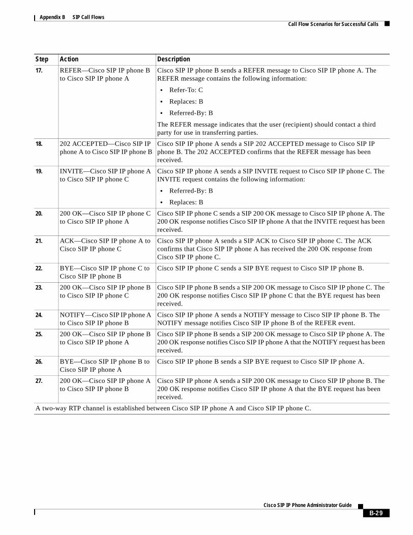
Appendix B SIP Call FlowsCall Flow Scenarios for Successful Calls
17. REFER—Cisco SIP IP phone B to Cisco SIP IP phone A
Cisco SIP IP phone B sends a REFER message to Cisco SIP IP phone A. The REFER message contains the following information:
• Refer-To: C
• Replaces: B
• Referred-By: B
The REFER message indicates that the user (recipient) should contact a third party for use in transferring parties.
18. 202 ACCEPTED—Cisco SIP IP phone A to Cisco SIP IP phone B
Cisco SIP IP phone A sends a SIP 202 ACCEPTED message to Cisco SIP IP phone B. The 202 ACCEPTED confirms that the REFER message has been received.
19. INVITE—Cisco SIP IP phone A to Cisco SIP IP phone C
Cisco SIP IP phone A sends a SIP INVITE request to Cisco SIP IP phone C. The INVITE request contains the following information:
• Referred-By: B
• Replaces: B
20. 200 OK—Cisco SIP IP phone C to Cisco SIP IP phone A
Cisco SIP IP phone C sends a SIP 200 OK message to Cisco SIP IP phone A. The 200 OK response notifies Cisco SIP IP phone A that the INVITE request has been received.
21. ACK—Cisco SIP IP phone A to Cisco SIP IP phone C
Cisco SIP IP phone A sends a SIP ACK to Cisco SIP IP phone C. The ACK confirms that Cisco SIP IP phone A has received the 200 OK response from Cisco SIP IP phone C.
22. BYE—Cisco SIP IP phone C to Cisco SIP IP phone B
Cisco SIP IP phone C sends a SIP BYE request to Cisco SIP IP phone B.
23. 200 OK—Cisco SIP IP phone B to Cisco SIP IP phone C
Cisco SIP IP phone B sends a SIP 200 OK message to Cisco SIP IP phone C. The 200 OK response notifies Cisco SIP IP phone C that the BYE request has been received.
24. NOTIFY—Cisco SIP IP phone A to Cisco SIP IP phone B
Cisco SIP IP phone A sends a NOTIFY message to Cisco SIP IP phone B. The NOTIFY message notifies Cisco SIP IP phone B of the REFER event.
25. 200 OK—Cisco SIP IP phone B to Cisco SIP IP phone A
Cisco SIP IP phone B sends a SIP 200 OK message to Cisco SIP IP phone A. The 200 OK response notifies Cisco SIP IP phone A that the NOTIFY request has been received.
26. BYE—Cisco SIP IP phone B to Cisco SIP IP phone A
Cisco SIP IP phone B sends a SIP BYE request to Cisco SIP IP phone A.
27. 200 OK—Cisco SIP IP phone A to Cisco SIP IP phone B
Cisco SIP IP phone A sends a SIP 200 OK message to Cisco SIP IP phone B. The 200 OK response notifies Cisco SIP IP phone A that the BYE request has been received.
A two-way RTP channel is established between Cisco SIP IP phone A and Cisco SIP IP phone C.
Step Action Description
B-29Cisco SIP IP Phone Administrator Guide
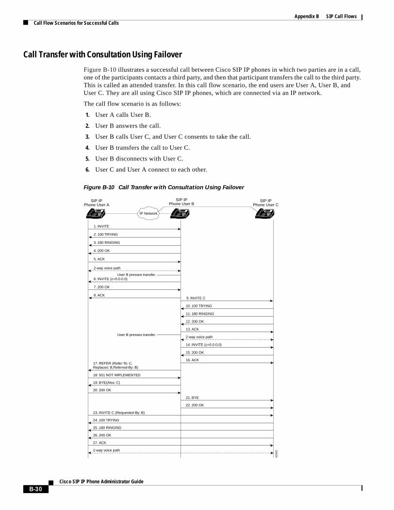
Appendix B SIP Call FlowsCall Flow Scenarios for Successful Calls
Call Transfer with Consultation Using Failover
Figure B-10 illustrates a successful call between Cisco SIP IP phones in which two parties are in a call, one of the participants contacts a third party, and then that participant transfers the call to the third party. This is called an attended transfer. In this call flow scenario, the end users are User A, User B, and User C. They are all using Cisco SIP IP phones, which are connected via an IP network.
The call flow scenario is as follows:
1. User A calls User B.
2. User B answers the call.
3. User B calls User C, and User C consents to take the call.
4. User B transfers the call to User C.
5. User B disconnects with User C.
6. User C and User A connect to each other.
Figure B-10 Call Transfer with Consultation Using Failover
IP Network
SIP IPPhone User B
IP IP
2. 100 TRYING
3. 180 RINGING
4. 200 OK
11. 180 RINGING
12. 200 OK
13. ACK
2-way voice path
14. INVITE (c=0.0.0.0)
15. 200 OK
16. ACK17. REFER (Refer-To: C,Replaces: B,Referred-By: B)
18. 501 NOT IMPLEMENTED
19. BYE(Also: C)
20. 200 OK
21. BYE
22. 200 OK
23. INVITE C (Requested-By: B)
24. 100 TRYING
25. 180 RINGING
26. 200 OK
27. ACK
2-way voice path
5. ACK
2-way voice path
User B presses transfer.6. INVITE (c=0.0.0.0)
7. 200 OK
8. ACK9. INVITE C
10. 100 TRYING
1. INVITE
SIP IPPhone User A
SIP IPPhone User C
IP
6250
2
User B presses transfer.
B-30Cisco SIP IP Phone Administrator Guide

Appendix B SIP Call FlowsCall Flow Scenarios for Successful Calls
Step Action Description
1. INVITE—Cisco SIP IP phone A to Cisco SIP IP phone B
Cisco SIP IP phone A sends a SIP INVITE request to Cisco SIP IP phone B. The INVITE request is an invitation to User B to participate in a call session.
In the INVITE request:
• The phone number of User B is inserted in the Request-URI field in the form of a SIP URL. The SIP URL identifies the address of User B and takes a form similar to an e-mail address (user@host, where user is the telephone number and host is either a domain name or a numeric network address). For example, the Request-URI field in the INVITE request to User B appears as “INVITE sip:[email protected]; user=phone.” The “user=phone” parameter distinquishes that the Request-URI address is a telephone number rather than a username.
• Cisco SIP IP phone A is identified as the call session initiator in the From field.
• A unique numeric identifier is assigned to the call and is inserted in the Call-ID field.
• The transaction number within a single call leg is identified in the CSeq field.
• The media capability User A is ready to receive is specified.
2. 100 Trying—Cisco SIP IP phone B to Cisco SIP IP phone A
The Cisco SIP IP phone B sends a SIP 100 Trying response to Cisco SIP IP phone A. The 100 Trying response indicates that the INVITE request has been received by Cisco SIP IP phone B.
3. 180 Ringing—Cisco SIP IP phone B to Cisco SIP IP phone A
Cisco SIP IP phone B sends a SIP 180 Ringing response to Cisco SIP IP phone A.
4. 200 OK—Cisco SIP IP phone B to Cisco SIP IP phone A
Cisco SIP IP phone B sends a SIP 200 OK response to Cisco SIP IP phone A. The 200 OK response notifies Cisco SIP IP phone A that the connection has been made.
If Cisco SIP IP phone B supports the media capability advertised in the INVITE message sent by Cisco SIP IP phone A, it advertises the intersection of its own and Cisco SIP IP phone A’s media capability in the 200 OK response. If Cisco SIP IP phone B does not support the media capability advertised by Cisco SIP IP phone A, it sends back a 400 Bad Request response with a 304 Warning header field.
5. ACK—Cisco SIP IP phone A to Cisco SIP IP phone B
Cisco SIP IP phone A sends a SIP ACK to Cisco SIP IP phone B. The ACK confirms that Cisco SIP IP phone A has received the 200 OK response from Cisco SIP IP phone B.
The ACK might contain a message body with the final session description to be used by Cisco SIP IP phone B. If the message body of the ACK is empty, Cisco SIP IP phone B uses the session description in the INVITE request.
A two-way RTP channel is established between Cisco SIP IP phone A and Cisco SIP IP phone B.User B then selects the option to transfer the call to User C.
6. INVITE—Cisco SIP IP phone B to Cisco SIP IP phone A
Cisco SIP IP phone B sends a mid-call INVITE to Cisco SIP IP phone A with new SDP session parameters (IP address), which are used to place the call on hold.
Call_ID=1 SDP: c=IN IP4 0.0.0.0
B-31Cisco SIP IP Phone Administrator Guide
Appendix B SIP Call FlowsCall Flow Scenarios for Successful Calls
7. 200 OK—Cisco SIP IP phone A to Cisco SIP IP phone B
Cisco SIP IP phone A sends a SIP 200 OK response to Cisco SIP IP phone B.
8. ACK—Cisco SIP IP phone B to Cisco SIP IP phone A
Cisco SIP IP phone B sends a SIP ACK to Cisco SIP IP phone A. The ACK confirms that Cisco SIP IP phone B has received the 200 OK response from Cisco SIP IP phone A.
User B dials User C.
9. INVITE—Cisco SIP IP phone B to Cisco SIP IP phone C
Cisco SIP IP phone B sends a SIP INVITE request to Cisco SIP IP phone C. The INVITE request is an invitation to User C to participate in a call session.
10. 100 Trying—Cisco SIP IP phone C to Cisco SIP IP phone B
The Cisco SIP IP phone C sends a SIP 100 Trying response to Cisco SIP IP phone B. The 100 Trying response indicates that the INVITE request has been received by the Cisco SIP IP phone.
11. 180 Ringing—Cisco SIP IP phone C to Cisco SIP IP phone B
Cisco SIP IP phone C sends a SIP 180 Ringing response to Cisco SIP IP phone B.
12. 200 OK—Cisco SIP IP phone C to Cisco SIP IP phone B
Cisco SIP IP phone C sends a SIP 200 OK response to Cisco SIP IP phone B. The 200 OK response notifies Cisco SIP IP phone B that the connection has been made.
If Cisco SIP IP phone B supports the media capability advertised in the INVITE message sent by Cisco SIP IP phone A, it advertises the intersection of its own and Cisco SIP IP phone A’s media capability in the 200 OK response. If Cisco SIP IP phone B does not support the media capability advertised by Cisco SIP IP phone A, it sends back a 400 Bad Request response with a 304 Warning header field.
13. ACK—Cisco SIP IP phone B to Cisco SIP IP phone C
Cisco SIP IP phone B sends a SIP ACK to Cisco SIP IP phone C. The ACK confirms that Cisco SIP IP phone B has received the 200 OK response from Cisco SIP IP phone C.
The ACK might contain a message body with the final session description to be used by Cisco SIP IP phone C. If the message body of the ACK is empty, Cisco SIP IP phone C uses the session description in the INVITE request.
A two-way RTP channel is established between Cisco SIP IP phone B and Cisco SIP IP phone C.User B then selects the option to transfer the call to User C.
14. INVITE—Cisco SIP IP phone B to Cisco SIP IP phone A
Cisco SIP IP phone B sends a mid-call INVITE to Cisco SIP IP phone A with new SDP session parameters (IP address), which are used to place the call on hold.
Call_ID=1 SDP: c=IN IP4 0.0.0.0
The c= SDP field of the SIP INVITE contains an 0.0.0.0. This places the call in hold.
15. 200 OK—Cisco SIP IP phone A to Cisco SIP IP phone B
Cisco SIP IP phone A sends a SIP 200 OK response to Cisco SIP IP phone B.
16. ACK—Cisco SIP IP phone B to Cisco SIP IP phone C
Cisco SIP IP phone B sends a SIP ACK to Cisco SIP IP phone C. The ACK confirms that Cisco SIP IP phone B has received the 200 OK response from Cisco SIP IP phone C.
Step Action Description
B-32Cisco SIP IP Phone Administrator Guide
Appendix B SIP Call FlowsCall Flow Scenarios for Successful Calls
17. REFER—Cisco SIP IP phone B to Cisco SIP IP phone A
Cisco SIP IP phone B sends a REFER message to Cisco SIP IP phone A. The REFER message contains the following information:
• Refer-To: C
• Replaces: B
• Referred-By: B
The REFER message indicates that the user (recipient) should contact a third party for use in transferring parties.
18. 501 Not Implemented—Cisco SIP IP Phone A to Cisco SIP IP Phone B
Cisco SIP IP phone A sends a 501 Not Implemented message to Cisco SIP IP phone B. This message indicates that the REFER message is not supported and that Cisco SIP IP phone B should failover to Bye/Also.
19. BYE—Cisco SIP IP phone B to Cisco SIP IP phone A
Cisco SIP IP phone B sends a BYE message to Cisco SIP IP phone A. The BYE message includes the following information:
• Also: C
This message indicates that the 501 Not Implemented message was received in response to a REFER message.
20. 200 OK—Cisco SIP IP phone A to Cisco SIP IP phone B
Cisco SIP IP phone A sends a SIP 200 OK message to Cisco SIP IP phone B. The 200 OK response notifies Cisco SIP IP phone B that the BYE request has been received.
21. BYE—Cisco SIP IP phone B to Cisco SIP IP phone C
Cisco SIP IP phone B sends a SIP BYE request to Cisco SIP IP phone C.
22. 200 OK—Cisco SIP IP phone C to Cisco SIP IP phone B
Cisco SIP IP phone C sends a SIP 200 OK message to Cisco SIP IP phone B. The 200 OK response notifies Cisco SIP IP phone B that the BYE request has been received.
23. INVITE—Cisco SIP IP phone A to Cisco SIP IP phone C
Cisco SIP IP phone A sends a SIP INVITE request to Cisco SIP IP phone C. The INVITE request contains the following information:
• Requested-By: B
This message indicates that the INVITE was requested by Cisco SIP IP phone B.
24. 100 Trying—Cisco SIP IP phone C to Cisco SIP IP phone A
The Cisco SIP IP phone C sends a SIP 100 Trying response to Cisco SIP IP phone A. The 100 Trying response indicates that the INVITE request has been received by Cisco SIP IP phone C.
25. 180 Ringing—Cisco SIP IP phone C to Cisco SIP IP phone A
Cisco SIP IP phone C sends a SIP 180 Ringing response to Cisco SIP IP phone A.
26. 200 OK—Cisco SIP IP phone C to Cisco SIP IP phone A
Cisco SIP IP phone C sends a SIP 200 OK response to Cisco SIP IP phone A. The 200 OK response notifies Cisco SIP IP phone A that the connection has been made.
27. ACK—Cisco SIP IP phone A to Cisco SIP IP phone C
Cisco SIP IP phone A sends a SIP ACK to Cisco SIP IP phone C. The ACK confirms that Cisco SIP IP phone A has received the 200 OK response from Cisco SIP IP phone C.
A two-way RTP channel is established between Cisco SIP IP phone A and Cisco SIP IP phone C.
Step Action Description
B-33Cisco SIP IP Phone Administrator Guide
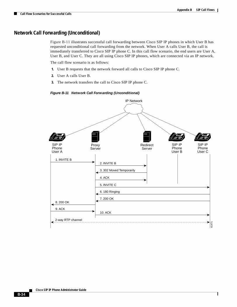
Appendix B SIP Call FlowsCall Flow Scenarios for Successful Calls
Network Call Forwarding (Unconditional)
Figure B-11 illustrates successful call forwarding between Cisco SIP IP phones in which User B has requested unconditional call forwarding from the network. When User A calls User B, the call is immediately transferred to Cisco SIP IP phone C. In this call flow scenario, the end users are User A, User B, and User C. They are all using Cisco SIP IP phones, which are connected via an IP network.
The call flow scenario is as follows:
1. User B requests that the network forward all calls to Cisco SIP IP phone C.
2. User A calls User B.
3. The network transfers the call to Cisco SIP IP phone C.
Figure B-11 Network Call Forwarding (Unconditional)
IP IP
8. 200 OK
5. INVITE C
7. 200 OK
10. ACK
6. 180 Ringing
1. INVITE B
9. ACK
3. 302 Moved Temporarily
2. INVITE B
4. ACK
IP Network
SIP IPPhoneUser A
SIP IPPhoneUser B
SIP IPPhoneUser C
ProxyServer
RedirectServer
IP
4147
1
2-way RTP channel
B-34Cisco SIP IP Phone Administrator Guide
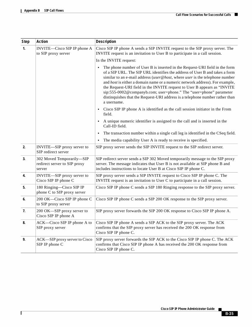
Appendix B SIP Call FlowsCall Flow Scenarios for Successful Calls
Step Action Description
1. INVITE—Cisco SIP IP phone A to SIP proxy server
Cisco SIP IP phone A sends a SIP INVITE request to the SIP proxy server. The INVITE request is an invitation to User B to participate in a call session.
In the INVITE request:
• The phone number of User B is inserted in the Request-URI field in the form of a SIP URL. The SIP URL identifies the address of User B and takes a form similar to an e-mail address (user@host, where user is the telephone number and host is either a domain name or a numeric network address). For example, the Request-URI field in the INVITE request to User B appears as “INVITE sip:[email protected]; user=phone.” The “user=phone” parameter distinquishes that the Request-URI address is a telephone number rather than a username.
• Cisco SIP IP phone A is identified as the call session initiator in the From field.
• A unique numeric identifier is assigned to the call and is inserted in the Call-ID field.
• The transaction number within a single call leg is identified in the CSeq field.
• The media capability User A is ready to receive is specified.
2. INVITE—SIP proxy server to SIP redirect server
SIP proxy server sends the SIP INVITE request to the SIP redirect server.
3. 302 Moved Temporarily—SIP redirect server to SIP proxy server
SIP redirect server sends a SIP 302 Moved temporarily message to the SIP proxy server. The message indicates that User B is not available at SIP phone B and includes instructions to locate User B at Cisco SIP IP phone C.
4. INVITE—SIP proxy server to Cisco SIP IP phone C
SIP proxy server sends a SIP INVITE request to Cisco SIP IP phone C. The INVITE request is an invitation to User C to participate in a call session.
5. 180 Ringing—Cisco SIP IP phone C to SIP proxy server
Cisco SIP IP phone C sends a SIP 180 Ringing response to the SIP proxy server.
6. 200 OK—Cisco SIP IP phone C to SIP proxy server
Cisco SIP IP phone C sends a SIP 200 OK response to the SIP proxy server.
7. 200 OK—SIP proxy server to Cisco SIP IP phone A
SIP proxy server forwards the SIP 200 OK response to Cisco SIP IP phone A.
8. ACK—Cisco SIP IP phone A to SIP proxy server
Cisco SIP IP phone A sends a SIP ACK to the SIP proxy server. The ACK confirms that the SIP proxy server has received the 200 OK response from Cisco SIP IP phone C.
9. ACK—SIP proxy server to Cisco SIP IP phone C
SIP proxy server forwards the SIP ACK to the Cisco SIP IP phone C. The ACK confirms that Cisco SIP IP phone A has received the 200 OK response from Cisco SIP IP phone C.
B-35Cisco SIP IP Phone Administrator Guide
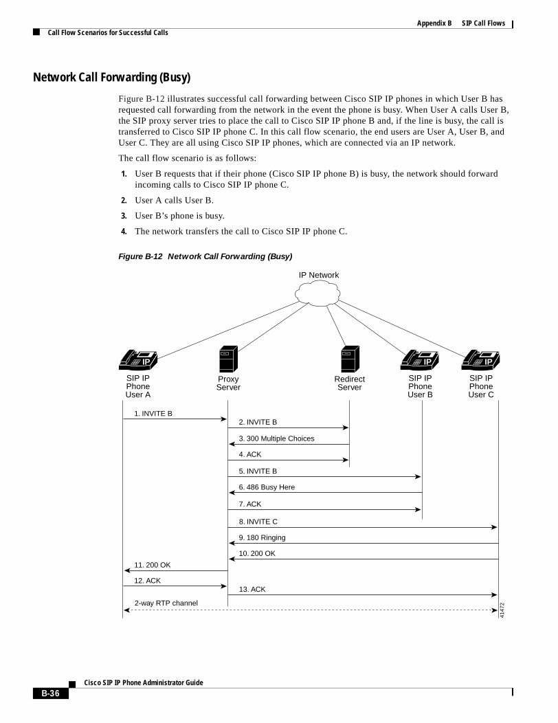
Appendix B SIP Call FlowsCall Flow Scenarios for Successful Calls
Network Call Forwarding (Busy)
Figure B-12 illustrates successful call forwarding between Cisco SIP IP phones in which User B has requested call forwarding from the network in the event the phone is busy. When User A calls User B, the SIP proxy server tries to place the call to Cisco SIP IP phone B and, if the line is busy, the call is transferred to Cisco SIP IP phone C. In this call flow scenario, the end users are User A, User B, and User C. They are all using Cisco SIP IP phones, which are connected via an IP network.
The call flow scenario is as follows:
1. User B requests that if their phone (Cisco SIP IP phone B) is busy, the network should forward incoming calls to Cisco SIP IP phone C.
2. User A calls User B.
3. User B’s phone is busy.
4. The network transfers the call to Cisco SIP IP phone C.
Figure B-12 Network Call Forwarding (Busy)
IP IP
11. 200 OK
5. INVITE B
9. 180 Ringing
10. 200 OK
13. ACK
8. INVITE C
6. 486 Busy Here
7. ACK
1. INVITE B
12. ACK
3. 300 Multiple Choices
2. INVITE B
4. ACK
IP Network
SIP IPPhoneUser A
SIP IPPhoneUser B
SIP IPPhoneUser C
ProxyServer
RedirectServer
IP
4147
22-way RTP channel
B-36Cisco SIP IP Phone Administrator Guide
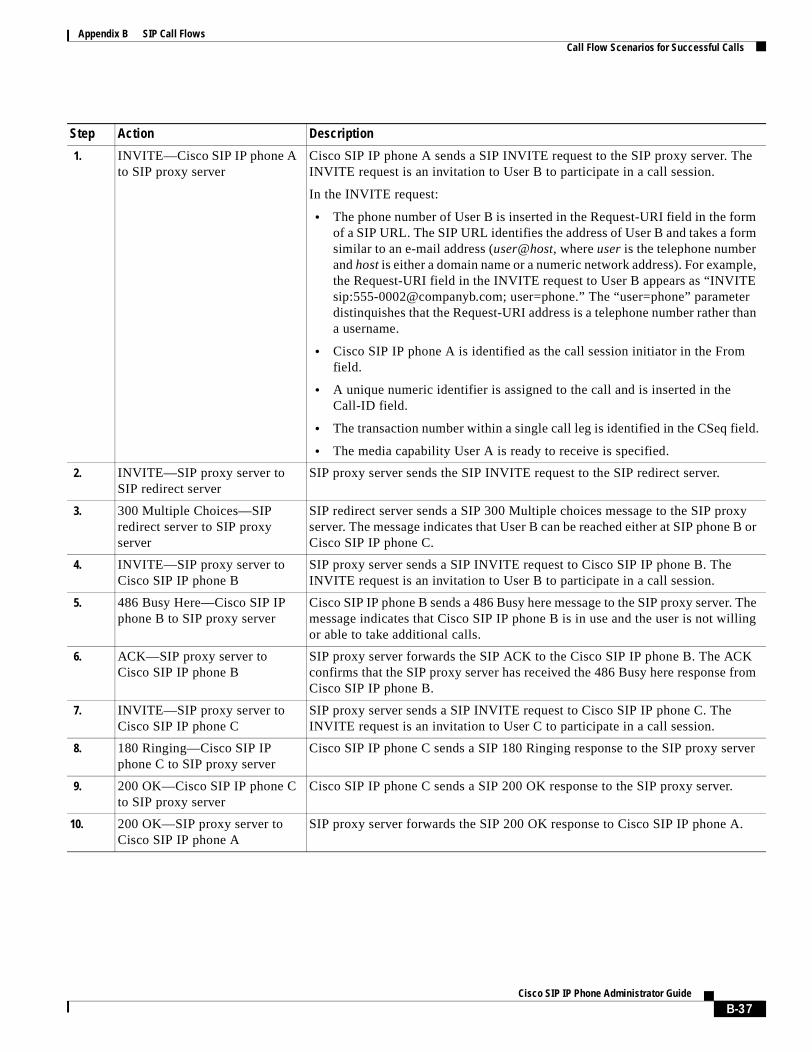
Appendix B SIP Call FlowsCall Flow Scenarios for Successful Calls
Step Action Description
1. INVITE—Cisco SIP IP phone A to SIP proxy server
Cisco SIP IP phone A sends a SIP INVITE request to the SIP proxy server. The INVITE request is an invitation to User B to participate in a call session.
In the INVITE request:
• The phone number of User B is inserted in the Request-URI field in the form of a SIP URL. The SIP URL identifies the address of User B and takes a form similar to an e-mail address (user@host, where user is the telephone number and host is either a domain name or a numeric network address). For example, the Request-URI field in the INVITE request to User B appears as “INVITE sip:[email protected]; user=phone.” The “user=phone” parameter distinquishes that the Request-URI address is a telephone number rather than a username.
• Cisco SIP IP phone A is identified as the call session initiator in the From field.
• A unique numeric identifier is assigned to the call and is inserted in the Call-ID field.
• The transaction number within a single call leg is identified in the CSeq field.
• The media capability User A is ready to receive is specified.
2. INVITE—SIP proxy server to SIP redirect server
SIP proxy server sends the SIP INVITE request to the SIP redirect server.
3. 300 Multiple Choices—SIP redirect server to SIP proxy server
SIP redirect server sends a SIP 300 Multiple choices message to the SIP proxy server. The message indicates that User B can be reached either at SIP phone B or Cisco SIP IP phone C.
4. INVITE—SIP proxy server to Cisco SIP IP phone B
SIP proxy server sends a SIP INVITE request to Cisco SIP IP phone B. The INVITE request is an invitation to User B to participate in a call session.
5. 486 Busy Here—Cisco SIP IP phone B to SIP proxy server
Cisco SIP IP phone B sends a 486 Busy here message to the SIP proxy server. The message indicates that Cisco SIP IP phone B is in use and the user is not willing or able to take additional calls.
6. ACK—SIP proxy server to Cisco SIP IP phone B
SIP proxy server forwards the SIP ACK to the Cisco SIP IP phone B. The ACK confirms that the SIP proxy server has received the 486 Busy here response from Cisco SIP IP phone B.
7. INVITE—SIP proxy server to Cisco SIP IP phone C
SIP proxy server sends a SIP INVITE request to Cisco SIP IP phone C. The INVITE request is an invitation to User C to participate in a call session.
8. 180 Ringing—Cisco SIP IP phone C to SIP proxy server
Cisco SIP IP phone C sends a SIP 180 Ringing response to the SIP proxy server
9. 200 OK—Cisco SIP IP phone C to SIP proxy server
Cisco SIP IP phone C sends a SIP 200 OK response to the SIP proxy server.
10. 200 OK—SIP proxy server to Cisco SIP IP phone A
SIP proxy server forwards the SIP 200 OK response to Cisco SIP IP phone A.
B-37Cisco SIP IP Phone Administrator Guide

Appendix B SIP Call FlowsCall Flow Scenarios for Successful Calls
11. ACK—Cisco SIP IP phone A to SIP proxy server
Cisco SIP IP phone A sends a SIP ACK to the SIP proxy server. The ACK confirms that Cisco SIP IP phone A has received the 200 OK response from Cisco SIP IP phone C.
12. ACK—SIP proxy server to Cisco SIP IP phone C
SIP proxy server forwards the SIP ACK to the Cisco SIP IP phone C. The ACK confirms that Cisco SIP IP phone A has received the 200 OK response from Cisco SIP IP phone C.
Step Action Description
B-38Cisco SIP IP Phone Administrator Guide
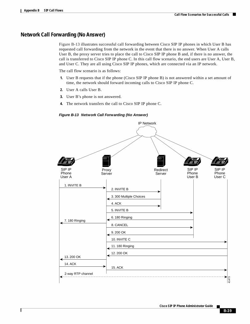
Appendix B SIP Call FlowsCall Flow Scenarios for Successful Calls
Network Call Forwarding (No Answer)
Figure B-13 illustrates successful call forwarding between Cisco SIP IP phones in which User B has requested call forwarding from the network in the event that there is no answer. When User A calls User B, the proxy server tries to place the call to Cisco SIP IP phone B and, if there is no answer, the call is transferred to Cisco SIP IP phone C. In this call flow scenario, the end users are User A, User B, and User C. They are all using Cisco SIP IP phones, which are connected via an IP network.
The call flow scenario is as follows:
1. User B requests that if the phone (Cisco SIP IP phone B) is not answered within a set amount of time, the network should forward incoming calls to Cisco SIP IP phone C.
2. User A calls User B.
3. User B’s phone is not answered.
4. The network transfers the call to Cisco SIP IP phone C.
Figure B-13 Network Call Forwarding (No Answer)
IP IP
13. 200 OK
7. 180 Ringing
5. INVITE B
9. 200 OK
12. 200 OK
11. 180 Ringing
15. ACK
10. INVITE C
8. CANCEL
6. 180 Ringing
1. INVITE B
14. ACK
3. 300 Multiple Choices
2. INVITE B
4. ACK
IP Network
SIP IPPhoneUser A
SIP IPPhoneUser B
SIP IPPhoneUser C
ProxyServer
RedirectServer
IP
4147
3
2-way RTP channel
B-39Cisco SIP IP Phone Administrator Guide
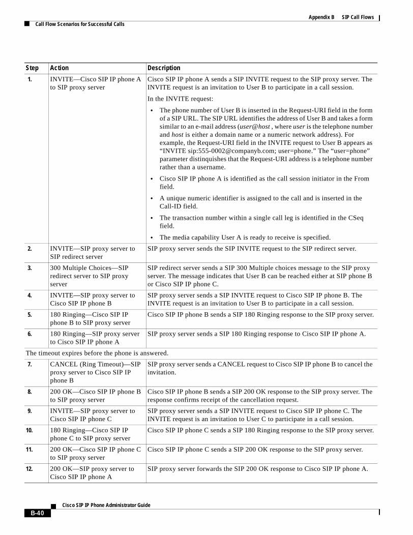
Appendix B SIP Call FlowsCall Flow Scenarios for Successful Calls
Step Action Description
1. INVITE—Cisco SIP IP phone A to SIP proxy server
Cisco SIP IP phone A sends a SIP INVITE request to the SIP proxy server. The INVITE request is an invitation to User B to participate in a call session.
In the INVITE request:
• The phone number of User B is inserted in the Request-URI field in the form of a SIP URL. The SIP URL identifies the address of User B and takes a form similar to an e-mail address (user@host , where user is the telephone number and host is either a domain name or a numeric network address). For example, the Request-URI field in the INVITE request to User B appears as “INVITE sip:[email protected]; user=phone.” The “user=phone” parameter distinquishes that the Request-URI address is a telephone number rather than a username.
• Cisco SIP IP phone A is identified as the call session initiator in the From field.
• A unique numeric identifier is assigned to the call and is inserted in the Call-ID field.
• The transaction number within a single call leg is identified in the CSeq field.
• The media capability User A is ready to receive is specified.
2. INVITE—SIP proxy server to SIP redirect server
SIP proxy server sends the SIP INVITE request to the SIP redirect server.
3. 300 Multiple Choices—SIP redirect server to SIP proxy server
SIP redirect server sends a SIP 300 Multiple choices message to the SIP proxy server. The message indicates that User B can be reached either at SIP phone B or Cisco SIP IP phone C.
4. INVITE—SIP proxy server to Cisco SIP IP phone B
SIP proxy server sends a SIP INVITE request to Cisco SIP IP phone B. The INVITE request is an invitation to User B to participate in a call session.
5. 180 Ringing—Cisco SIP IP phone B to SIP proxy server
Cisco SIP IP phone B sends a SIP 180 Ringing response to the SIP proxy server.
6. 180 Ringing—SIP proxy server to Cisco SIP IP phone A
SIP proxy server sends a SIP 180 Ringing response to Cisco SIP IP phone A.
The timeout expires before the phone is answered.
7. CANCEL (Ring Timeout)—SIP proxy server to Cisco SIP IP phone B
SIP proxy server sends a CANCEL request to Cisco SIP IP phone B to cancel the invitation.
8. 200 OK—Cisco SIP IP phone B to SIP proxy server
Cisco SIP IP phone B sends a SIP 200 OK response to the SIP proxy server. The response confirms receipt of the cancellation request.
9. INVITE—SIP proxy server to Cisco SIP IP phone C
SIP proxy server sends a SIP INVITE request to Cisco SIP IP phone C. The INVITE request is an invitation to User C to participate in a call session.
10. 180 Ringing—Cisco SIP IP phone C to SIP proxy server
Cisco SIP IP phone C sends a SIP 180 Ringing response to the SIP proxy server.
11. 200 OK—Cisco SIP IP phone C to SIP proxy server
Cisco SIP IP phone C sends a SIP 200 OK response to the SIP proxy server.
12. 200 OK—SIP proxy server to Cisco SIP IP phone A
SIP proxy server forwards the SIP 200 OK response to Cisco SIP IP phone A.
B-40Cisco SIP IP Phone Administrator Guide

Appendix B SIP Call FlowsCall Flow Scenarios for Successful Calls
13. ACK—Cisco SIP IP phone A to SIP proxy server
Cisco SIP IP phone A sends a SIP ACK to the SIP proxy server. The ACK confirms that Cisco SIP IP phone A has received the 200 OK response from Cisco SIP IP phone C.
14. ACK—SIP proxy server to Cisco SIP IP phone C
SIP proxy server forwards the SIP ACK to the Cisco SIP IP phone C. The ACK confirms that Cisco SIP IP phone A has received the 200 OK response from Cisco SIP IP phone C.
Step Action Description
B-41Cisco SIP IP Phone Administrator Guide

Appendix B SIP Call FlowsCall Flow Scenarios for Successful Calls
Three-Way Calling
Figure B-14 illustrates successful three-way calling between Cisco SIP IP phones in which User B mixes two RTP channels and therefore establishes a conference bridge between User A and User C. In this call flow scenario, the end users are User A, User B, and User C. They are all using Cisco SIP IP phones, which are connected via an IP network.
The call flow scenario is as follows:
1. User A calls User B.
2. User B answers the call.
3. User B puts User A on hold.
4. User B calls User C.
5. User C answers the call.
6. User B takes User A off hold.
Figure B-14 Three-Way Calling
4. ACK
9. 180 Ringing
10. 200 OK
11. ACK
8. INVITE C (Call-ID=2)
2-way RTP channel 1 between Users A and B established
5. INVITE (Call-ID=1, c=IN IP40.0.0.0)
1. INVITE B (Call-ID=1)
3. 200 OK
2. 180 Ringing
6. 200 OK
12. INVITE A (Call-ID=1, c=IN IP4 IP-User B)
13. 200 OK
7. ACK
IP Network
SIP IPPhoneUser A
SIP IPPhoneUser B
SIP IPPhoneUser C
ProxyServer
RedirectServer
5021
2
User A is taken off hold. The RTP channel 1 between User A and B is re-established.
User A is on hold. The RTP channel 1 between User A and B is torn down.
User B mixes the RTP channels 1 and 2 and establishes a conference brigde between Users A and C
2-way RTP channel 2between User B andC is established
IPIPIP
B-42Cisco SIP IP Phone Administrator Guide
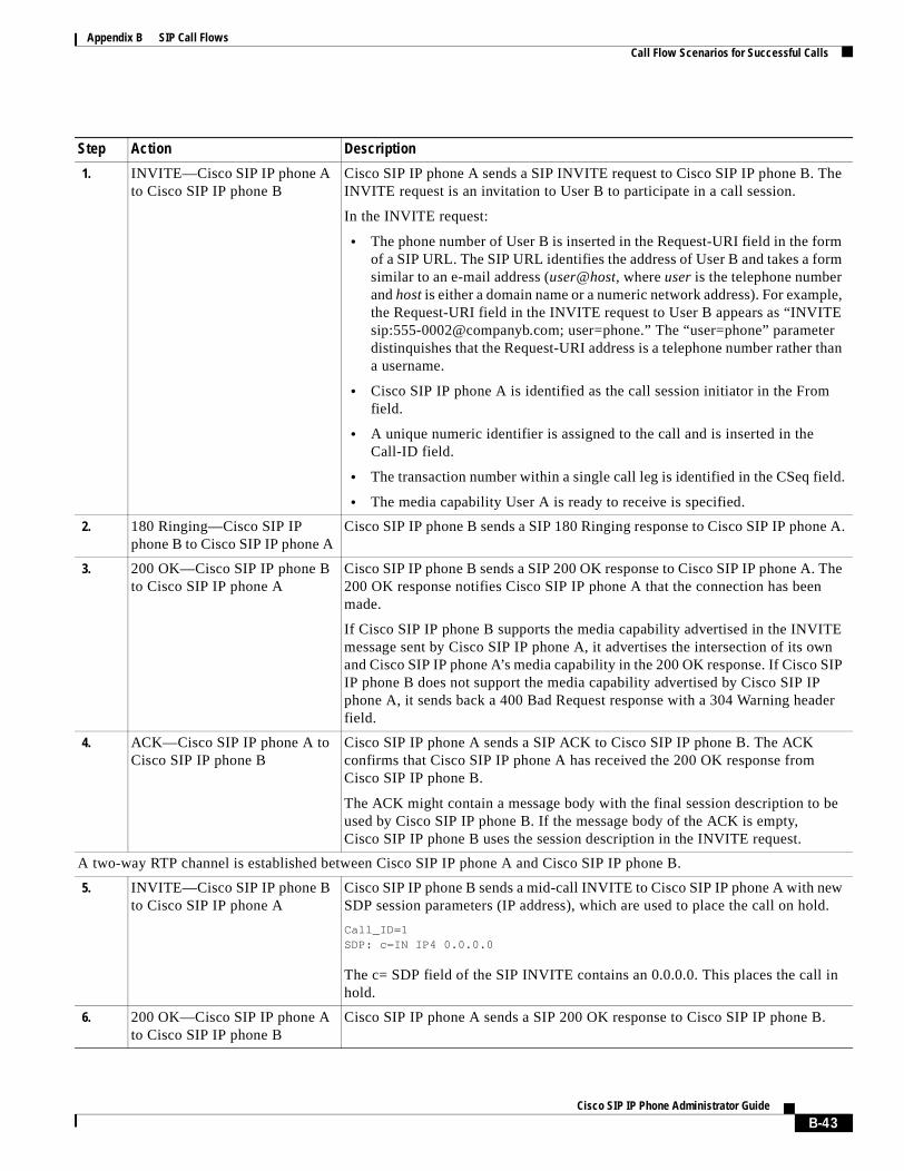
Appendix B SIP Call FlowsCall Flow Scenarios for Successful Calls
Step Action Description
1. INVITE—Cisco SIP IP phone A to Cisco SIP IP phone B
Cisco SIP IP phone A sends a SIP INVITE request to Cisco SIP IP phone B. The INVITE request is an invitation to User B to participate in a call session.
In the INVITE request:
• The phone number of User B is inserted in the Request-URI field in the form of a SIP URL. The SIP URL identifies the address of User B and takes a form similar to an e-mail address (user@host, where user is the telephone number and host is either a domain name or a numeric network address). For example, the Request-URI field in the INVITE request to User B appears as “INVITE sip:[email protected]; user=phone.” The “user=phone” parameter distinquishes that the Request-URI address is a telephone number rather than a username.
• Cisco SIP IP phone A is identified as the call session initiator in the From field.
• A unique numeric identifier is assigned to the call and is inserted in the Call-ID field.
• The transaction number within a single call leg is identified in the CSeq field.
• The media capability User A is ready to receive is specified.
2. 180 Ringing—Cisco SIP IP phone B to Cisco SIP IP phone A
Cisco SIP IP phone B sends a SIP 180 Ringing response to Cisco SIP IP phone A.
3. 200 OK—Cisco SIP IP phone B to Cisco SIP IP phone A
Cisco SIP IP phone B sends a SIP 200 OK response to Cisco SIP IP phone A. The 200 OK response notifies Cisco SIP IP phone A that the connection has been made.
If Cisco SIP IP phone B supports the media capability advertised in the INVITE message sent by Cisco SIP IP phone A, it advertises the intersection of its own and Cisco SIP IP phone A’s media capability in the 200 OK response. If Cisco SIP IP phone B does not support the media capability advertised by Cisco SIP IP phone A, it sends back a 400 Bad Request response with a 304 Warning header field.
4. ACK—Cisco SIP IP phone A to Cisco SIP IP phone B
Cisco SIP IP phone A sends a SIP ACK to Cisco SIP IP phone B. The ACK confirms that Cisco SIP IP phone A has received the 200 OK response from Cisco SIP IP phone B.
The ACK might contain a message body with the final session description to be used by Cisco SIP IP phone B. If the message body of the ACK is empty, Cisco SIP IP phone B uses the session description in the INVITE request.
A two-way RTP channel is established between Cisco SIP IP phone A and Cisco SIP IP phone B.
5. INVITE—Cisco SIP IP phone B to Cisco SIP IP phone A
Cisco SIP IP phone B sends a mid-call INVITE to Cisco SIP IP phone A with new SDP session parameters (IP address), which are used to place the call on hold.
Call_ID=1 SDP: c=IN IP4 0.0.0.0
The c= SDP field of the SIP INVITE contains an 0.0.0.0. This places the call in hold.
6. 200 OK—Cisco SIP IP phone A to Cisco SIP IP phone B
Cisco SIP IP phone A sends a SIP 200 OK response to Cisco SIP IP phone B.
B-43Cisco SIP IP Phone Administrator Guide
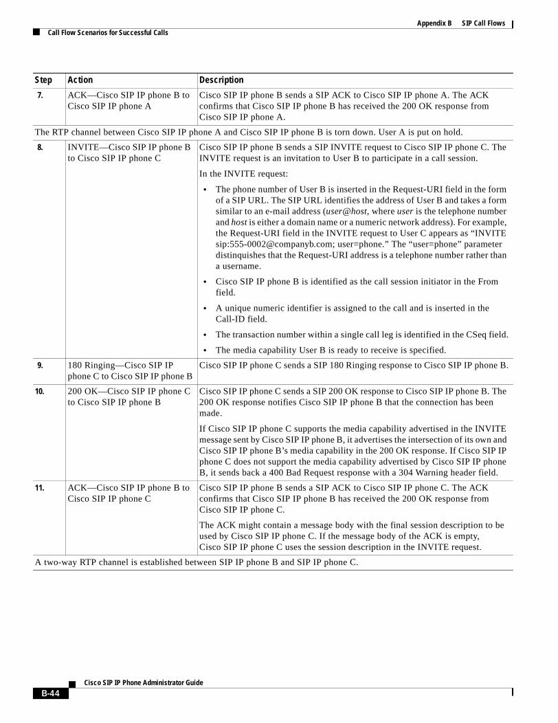
Appendix B SIP Call FlowsCall Flow Scenarios for Successful Calls
7. ACK—Cisco SIP IP phone B to Cisco SIP IP phone A
Cisco SIP IP phone B sends a SIP ACK to Cisco SIP IP phone A. The ACK confirms that Cisco SIP IP phone B has received the 200 OK response from Cisco SIP IP phone A.
The RTP channel between Cisco SIP IP phone A and Cisco SIP IP phone B is torn down. User A is put on hold.
8. INVITE—Cisco SIP IP phone B to Cisco SIP IP phone C
Cisco SIP IP phone B sends a SIP INVITE request to Cisco SIP IP phone C. The INVITE request is an invitation to User B to participate in a call session.
In the INVITE request:
• The phone number of User B is inserted in the Request-URI field in the form of a SIP URL. The SIP URL identifies the address of User B and takes a form similar to an e-mail address (user@host, where user is the telephone number and host is either a domain name or a numeric network address). For example, the Request-URI field in the INVITE request to User C appears as “INVITE sip:[email protected]; user=phone.” The “user=phone” parameter distinquishes that the Request-URI address is a telephone number rather than a username.
• Cisco SIP IP phone B is identified as the call session initiator in the From field.
• A unique numeric identifier is assigned to the call and is inserted in the Call-ID field.
• The transaction number within a single call leg is identified in the CSeq field.
• The media capability User B is ready to receive is specified.
9. 180 Ringing—Cisco SIP IP phone C to Cisco SIP IP phone B
Cisco SIP IP phone C sends a SIP 180 Ringing response to Cisco SIP IP phone B.
10. 200 OK—Cisco SIP IP phone C to Cisco SIP IP phone B
Cisco SIP IP phone C sends a SIP 200 OK response to Cisco SIP IP phone B. The 200 OK response notifies Cisco SIP IP phone B that the connection has been made.
If Cisco SIP IP phone C supports the media capability advertised in the INVITE message sent by Cisco SIP IP phone B, it advertises the intersection of its own and Cisco SIP IP phone B’s media capability in the 200 OK response. If Cisco SIP IP phone C does not support the media capability advertised by Cisco SIP IP phone B, it sends back a 400 Bad Request response with a 304 Warning header field.
11. ACK—Cisco SIP IP phone B to Cisco SIP IP phone C
Cisco SIP IP phone B sends a SIP ACK to Cisco SIP IP phone C. The ACK confirms that Cisco SIP IP phone B has received the 200 OK response from Cisco SIP IP phone C.
The ACK might contain a message body with the final session description to be used by Cisco SIP IP phone C. If the message body of the ACK is empty, Cisco SIP IP phone C uses the session description in the INVITE request.
A two-way RTP channel is established between SIP IP phone B and SIP IP phone C.
Step Action Description
B-44Cisco SIP IP Phone Administrator Guide
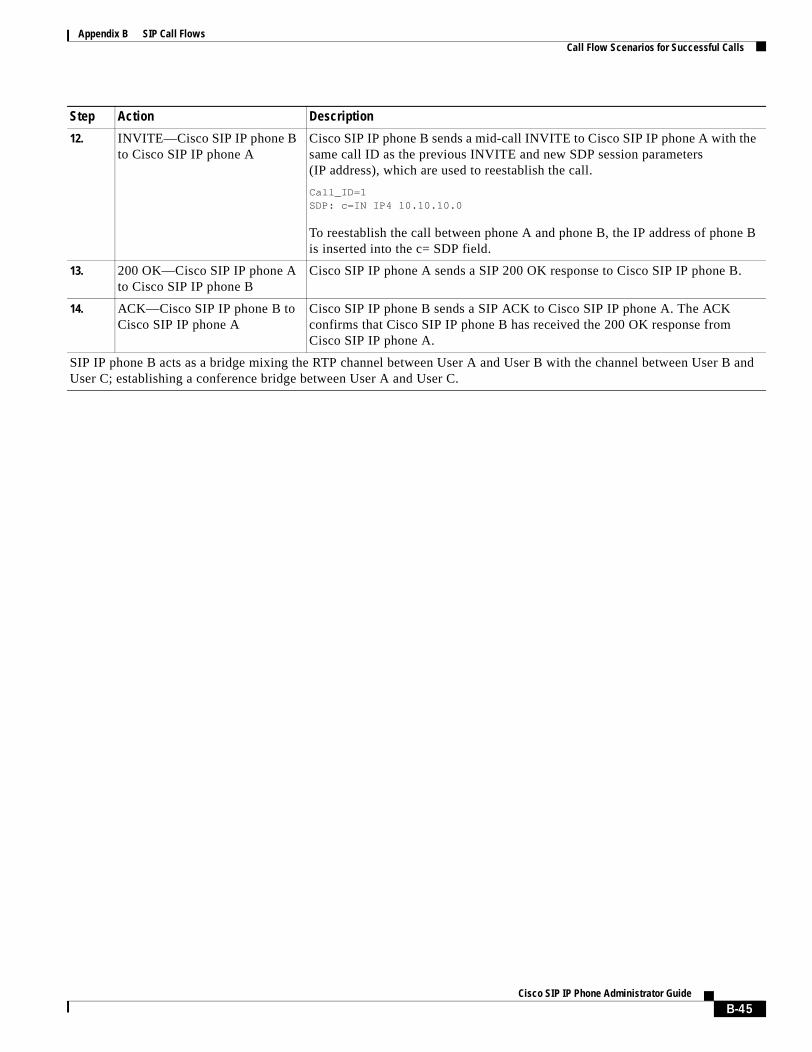
Appendix B SIP Call FlowsCall Flow Scenarios for Successful Calls
12. INVITE—Cisco SIP IP phone B to Cisco SIP IP phone A
Cisco SIP IP phone B sends a mid-call INVITE to Cisco SIP IP phone A with the same call ID as the previous INVITE and new SDP session parameters (IP address), which are used to reestablish the call.
Call_ID=1 SDP: c=IN IP4 10.10.10.0
To reestablish the call between phone A and phone B, the IP address of phone B is inserted into the c= SDP field.
13. 200 OK—Cisco SIP IP phone A to Cisco SIP IP phone B
Cisco SIP IP phone A sends a SIP 200 OK response to Cisco SIP IP phone B.
14. ACK—Cisco SIP IP phone B to Cisco SIP IP phone A
Cisco SIP IP phone B sends a SIP ACK to Cisco SIP IP phone A. The ACK confirms that Cisco SIP IP phone B has received the 200 OK response from Cisco SIP IP phone A.
SIP IP phone B acts as a bridge mixing the RTP channel between User A and User B with the channel between User B and User C; establishing a conference bridge between User A and User C.
Step Action Description
B-45Cisco SIP IP Phone Administrator Guide
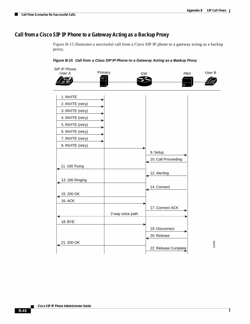
Appendix B SIP Call FlowsCall Flow Scenarios for Successful Calls
Call from a Cisco SIP IP Phone to a Gateway Acting as a Backup Proxy
Figure B-15 illustrates a successful call from a Cisco SIP IP phone to a gateway acting as a backup proxy.
Figure B-15 Call from a Cisco SIP IP Phone to a Gateway Acting as a Backup Proxy
IP
SIP IP PhoneUser A Primary
1. INVITE
2. INVITE (retry)
3. INVITE (retry)
4. INVITE (retry)
5. INVITE (retry)
6. INVITE (retry)
7. INVITE (retry)
8. INVITE (retry)
9. Setup
10. Call Proceeding
11. 100 Trying
12. Alerting
13. 180 Ringing
14. Connect
15. 200 OK
16. ACK
17. Connect ACK
18. BYE
2-way voice path
19. Disconnect
20. Release
22. Release Complete
21. 200 OK
GW PBX User B
6206
9
B-46Cisco SIP IP Phone Administrator Guide
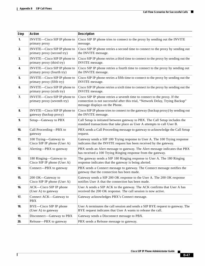
Appendix B SIP Call FlowsCall Flow Scenarios for Successful Calls
Step Action Description
1. INVITE—Cisco SIP IP phone to primary proxy
Cisco SIP IP phone tries to connect to the proxy by sending out the INVITE message.
2. INVITE—Cisco SIP IP phone to primary proxy (second try)
Cisco SIP IP phone retries a second time to connect to the proxy by sending out the INVITE message.
3. INVITE—Cisco SIP IP phone to primary proxy (third try)
Cisco SIP IP phone retries a third time to connect to the proxy by sending out the INVITE message.
4. INVITE—Cisco SIP IP phone to primary proxy (fourth try)
Cisco SIP IP phone retries a fourth time to connect to the proxy by sending out the INVITE message.
5. INVITE—Cisco SIP IP phone to primary proxy (fifth try)
Cisco SIP IP phone retries a fifth time to connect to the proxy by sending out the INVITE message.
6. INVITE—Cisco SIP IP phone to primary proxy (sixth try)
Cisco SIP IP phone retries a sixth time to connect to the proxy by sending out the INVITE message.
7. INVITE—Cisco SIP IP phone to primary proxy (seventh try)
Cisco SIP IP phone retries a seventh time to connect to the proxy. If the connection is not successful after this trial, “Network Delay, Trying Backup” message displays on the Phone.
8. INVITE—Cisco SIP IP phone to gateway (backup proxy)
Cisco SIP IP phone tries to connect to the gateway (backup proxy) by sending out the INVITE message.
9. Setup—Gateway to PBX Call Setup is initiated between gateway to PBX. The Call Setup includes the standard transactions that take place as User A attempts to call User B.
10. Call Proceeding—PBX to gateway
PBX sends a Call Proceeding message to gateway to acknowledge the Call Setup request.
11. 100 Trying—Gateway to Cisco SIP IP phone (User A)
Gateway sends a SIP 100 Trying response to User A. The 100 Trying response indicates that the INVITE request has been received by the gateway.
12. Alerting—PBX to gateway PBX sends an Alert message to gateway. The Alert message indicates that PBX has received a 100 Trying Ringing response from the gateway.
13. 180 Ringing—Gateway to Cisco SIP IP phone (User A)
The gateway sends a SIP 180 Ringing response to User A. The 180 Ringing response indicates that the gateway is being alerted.
14. Connect—PBX to gateway PBX sends a Connect message to gateway. The Connect message notifies the gateway that the connection has been made.
15. 200 OK—Gateway to Cisco SIP IP phone (User A)
Gateway sends a SIP 200 OK response to the User A. The 200 OK response notifies User A that the connection has been made.
16. ACK—Cisco SIP IP phone (User A) to gateway
User A sends a SIP ACK to the gateway. The ACK confirms that User A has received the 200 OK response. The call session is now active.
17. Connect ACK—Gateway to PBX
Gateway acknowledges PBX’s Connect message.
18. BYE—Cisco SIP IP phone (User A) to gateway
User A terminates the call session and sends a SIP BYE request to gateway. The BYE request indicates that User A wants to release the call.
19. Disconnect—Gateway to PBX Gateway sends a Disconnect message to PBX.
20. Release—PBX to gateway PBX sends a Release message to gateway.
B-47Cisco SIP IP Phone Administrator Guide
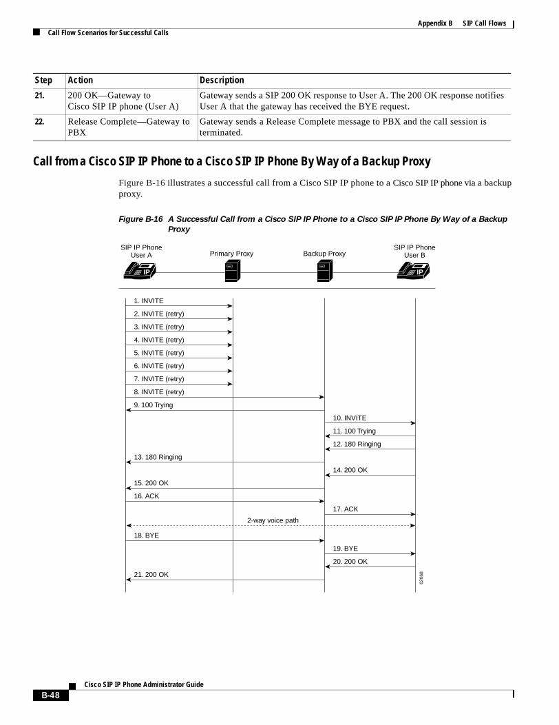
Appendix B SIP Call FlowsCall Flow Scenarios for Successful Calls
Call from a Cisco SIP IP Phone to a Cisco SIP IP Phone By Way of a Backup Proxy
Figure B-16 illustrates a successful call from a Cisco SIP IP phone to a Cisco SIP IP phone via a backup proxy.
Figure B-16 A Successful Call from a Cisco SIP IP Phone to a Cisco SIP IP Phone By Way of a Backup
Proxy
21. 200 OK—Gateway toCisco SIP IP phone (User A)
Gateway sends a SIP 200 OK response to User A. The 200 OK response notifies User A that the gateway has received the BYE request.
22. Release Complete—Gateway to PBX
Gateway sends a Release Complete message to PBX and the call session is terminated.
Step Action Description
IP IP
SIP IP PhoneUser A
1. INVITE
2. INVITE (retry)
3. INVITE (retry)
4. INVITE (retry)
5. INVITE (retry)
6. INVITE (retry)
7. INVITE (retry)
8. INVITE (retry)
9. 100 Trying
10. INVITE
11. 100 Trying
12. 180 Ringing
13. 180 Ringing
14. 200 OK
15. 200 OK
16. ACK
17. ACK
18. BYE
2-way voice path
19. BYE
20. 200 OK
21. 200 OK
Primary Proxy Backup ProxySIP IP Phone
User B
6206
8
B-48Cisco SIP IP Phone Administrator Guide
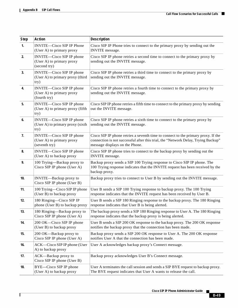
Appendix B SIP Call FlowsCall Flow Scenarios for Successful Calls
Step Action Description
1. INVITE—Cisco SIP IP Phone (User A) to primary proxy
Cisco SIP IP Phone tries to connect to the primary proxy by sending out the INVITE message.
2. INVITE—Cisco SIP IP phone (User A) to primary proxy (second try)
Cisco SIP IP phone retries a second time to connect to the primary proxy by sending out the INVITE message.
3. INVITE—Cisco SIP IP phone (User A) to primary proxy (third try)
Cisco SIP IP phone retries a third time to connect to the primary proxy by sending out the INVITE message.
4. INVITE—Cisco SIP IP phone (User A) to primary proxy (fourth try)
Cisco SIP IP phone retries a fourth time to connect to the primary proxy by sending out the INVITE message.
5. INVITE—Cisco SIP IP phone (User A) to primary proxy (fifth try)
Cisco SIP IP phone retries a fifth time to connect to the primary proxy by sending out the INVITE message.
6. INVITE—Cisco SIP IP phone (User A) to primary proxy (sixth try)
Cisco SIP IP phone retries a sixth time to connect to the primary proxy by sending out the INVITE message.
7. INVITE—Cisco SIP IP phone (User A) to primary proxy (seventh try)
Cisco SIP IP phone retries a seventh time to connect to the primary proxy. If the connection is not successful after this trial, the “Network Delay, Trying Backup” message displays on the Phone.
8. INVITE—Cisco SIP IP phone (User A) to backup proxy
Cisco SIP IP phone tries to connect to the backup proxy by sending out the INVITE message.
9. 100 Trying—Backup proxy to Cisco SIP IP phone (User A)
Backup proxy sends a SIP 100 Trying response to Cisco SIP IP phone. The 100 Trying response indicates that the INVITE request has been received by the backup proxy.
10. INVITE—Backup proxy to Cisco SIP IP phone (User B)
Backup proxy tries to connect to User B by sending out the INVITE message.
11. 100 Trying—Cisco SIP IP phone (User B) to backup proxy
User B sends a SIP 100 Trying response to backup proxy. The 100 Trying response indicates that the INVITE request has been received by User B.
12. 180 Ringing—Cisco SIP IP phone (User B) to backup proxy
User B sends a SIP 180 Ringing response to the backup proxy. The 180 Ringing response indicates that User B is being alerted.
13. 180 Ringing—Backup proxy to Cisco SIP IP phone (User A)
The backup proxy sends a SIP 180 Ringing response to User A. The 180 Ringing response indicates that the backup proxy is being alerted.
14. 200 OK—Cisco SIP IP phone (User B) to backup proxy
User B sends a SIP 200 OK response to the backup proxy. The 200 OK response notifies the backup proxy that the connection has been made.
15. 200 OK—Backup proxy to Cisco SIP IP phone (User A)
Backup proxy sends a SIP 200 OK response to User A. The 200 OK response notifies User A that the connection has been made.
16. ACK—Cisco SIP IP phone (User A) to backup proxy
User A acknowledges backup proxy’s Connect message.
17. ACK—Backup proxy to Cisco SIP IP phone (User B)
Backup proxy acknowledges User B’s Connect message.
18. BYE—Cisco SIP IP phone (User A) to backup proxy
User A terminates the call session and sends a SIP BYE request to backup proxy. The BYE request indicates that User A wants to release the call.
B-49Cisco SIP IP Phone Administrator Guide
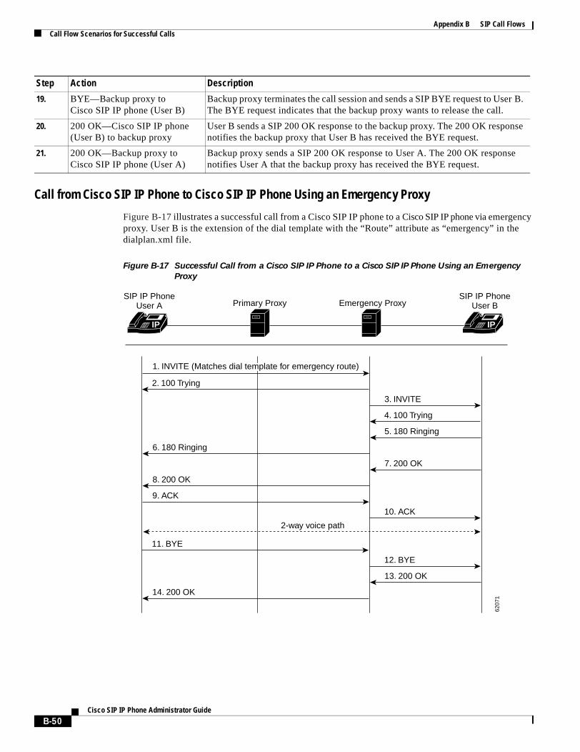
Appendix B SIP Call FlowsCall Flow Scenarios for Successful Calls
Call from Cisco SIP IP Phone to Cisco SIP IP Phone Using an Emergency Proxy
Figure B-17 illustrates a successful call from a Cisco SIP IP phone to a Cisco SIP IP phone via emergency proxy. User B is the extension of the dial template with the “Route” attribute as “emergency” in the dialplan.xml file.
Figure B-17 Successful Call from a Cisco SIP IP Phone to a Cisco SIP IP Phone Using an Emergency
Proxy
19. BYE—Backup proxy to Cisco SIP IP phone (User B)
Backup proxy terminates the call session and sends a SIP BYE request to User B. The BYE request indicates that the backup proxy wants to release the call.
20. 200 OK—Cisco SIP IP phone (User B) to backup proxy
User B sends a SIP 200 OK response to the backup proxy. The 200 OK response notifies the backup proxy that User B has received the BYE request.
21. 200 OK—Backup proxy to Cisco SIP IP phone (User A)
Backup proxy sends a SIP 200 OK response to User A. The 200 OK response notifies User A that the backup proxy has received the BYE request.
Step Action Description
IP IP
SIP IP PhoneUser A
SIP IP PhoneUser BPrimary Proxy Emergency Proxy
2. 100 Trying
3. INVITE
4. 100 Trying
5. 180 Ringing
6. 180 Ringing
7. 200 OK
8. 200 OK
9. ACK
10. ACK
11. BYE
12. BYE
13. 200 OK
14. 200 OK
2-way voice path
6207
1
1. INVITE (Matches dial template for emergency route)
B-50Cisco SIP IP Phone Administrator Guide
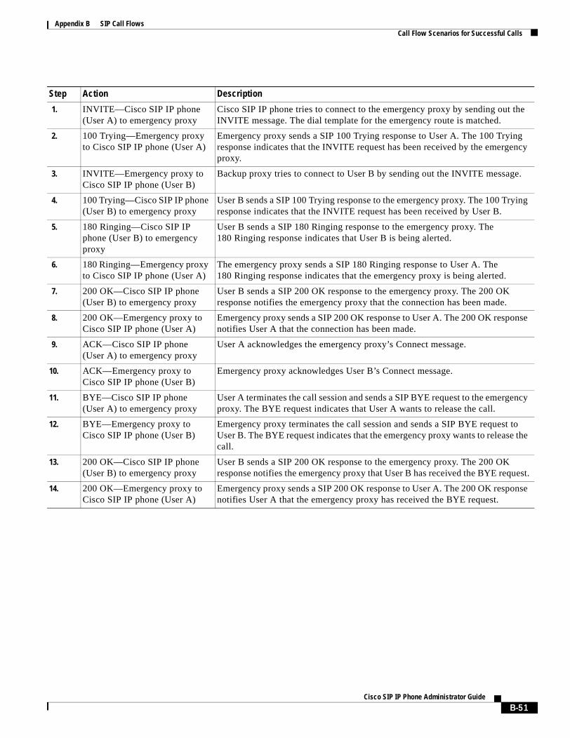
Appendix B SIP Call FlowsCall Flow Scenarios for Successful Calls
Step Action Description
1. INVITE—Cisco SIP IP phone (User A) to emergency proxy
Cisco SIP IP phone tries to connect to the emergency proxy by sending out the INVITE message. The dial template for the emergency route is matched.
2. 100 Trying—Emergency proxy to Cisco SIP IP phone (User A)
Emergency proxy sends a SIP 100 Trying response to User A. The 100 Trying response indicates that the INVITE request has been received by the emergency proxy.
3. INVITE—Emergency proxy to Cisco SIP IP phone (User B)
Backup proxy tries to connect to User B by sending out the INVITE message.
4. 100 Trying—Cisco SIP IP phone (User B) to emergency proxy
User B sends a SIP 100 Trying response to the emergency proxy. The 100 Trying response indicates that the INVITE request has been received by User B.
5. 180 Ringing—Cisco SIP IP phone (User B) to emergency proxy
User B sends a SIP 180 Ringing response to the emergency proxy. The 180 Ringing response indicates that User B is being alerted.
6. 180 Ringing—Emergency proxy to Cisco SIP IP phone (User A)
The emergency proxy sends a SIP 180 Ringing response to User A. The 180 Ringing response indicates that the emergency proxy is being alerted.
7. 200 OK—Cisco SIP IP phone (User B) to emergency proxy
User B sends a SIP 200 OK response to the emergency proxy. The 200 OK response notifies the emergency proxy that the connection has been made.
8. 200 OK—Emergency proxy to Cisco SIP IP phone (User A)
Emergency proxy sends a SIP 200 OK response to User A. The 200 OK response notifies User A that the connection has been made.
9. ACK—Cisco SIP IP phone (User A) to emergency proxy
User A acknowledges the emergency proxy’s Connect message.
10. ACK—Emergency proxy to Cisco SIP IP phone (User B)
Emergency proxy acknowledges User B’s Connect message.
11. BYE—Cisco SIP IP phone (User A) to emergency proxy
User A terminates the call session and sends a SIP BYE request to the emergency proxy. The BYE request indicates that User A wants to release the call.
12. BYE—Emergency proxy to Cisco SIP IP phone (User B)
Emergency proxy terminates the call session and sends a SIP BYE request to User B. The BYE request indicates that the emergency proxy wants to release the call.
13. 200 OK—Cisco SIP IP phone (User B) to emergency proxy
User B sends a SIP 200 OK response to the emergency proxy. The 200 OK response notifies the emergency proxy that User B has received the BYE request.
14. 200 OK—Emergency proxy to Cisco SIP IP phone (User A)
Emergency proxy sends a SIP 200 OK response to User A. The 200 OK response notifies User A that the emergency proxy has received the BYE request.
B-51Cisco SIP IP Phone Administrator Guide
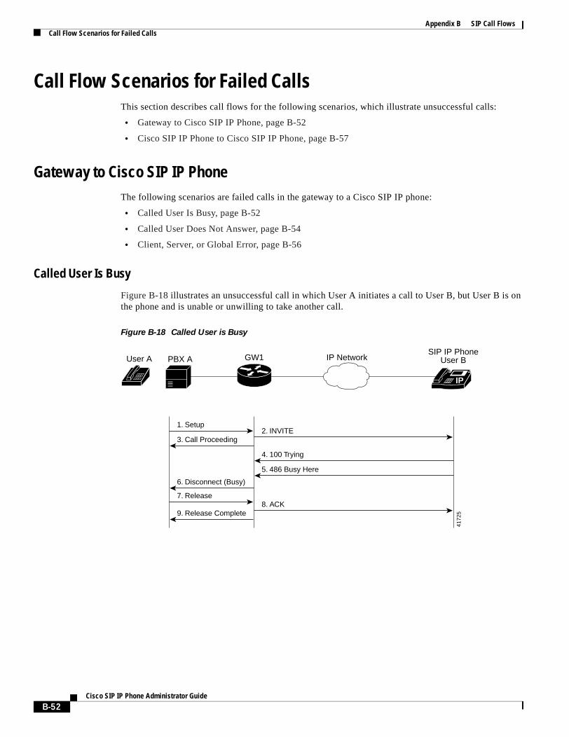
Appendix B SIP Call FlowsCall Flow Scenarios for Failed Calls
Call Flow Scenarios for Failed CallsThis section describes call flows for the following scenarios, which illustrate unsuccessful calls:
• Gateway to Cisco SIP IP Phone, page B-52
• Cisco SIP IP Phone to Cisco SIP IP Phone, page B-57
Gateway to Cisco SIP IP PhoneThe following scenarios are failed calls in the gateway to a Cisco SIP IP phone:
• Called User Is Busy, page B-52
• Called User Does Not Answer, page B-54
• Client, Server, or Global Error, page B-56
Called User Is Busy
Figure B-18 illustrates an unsuccessful call in which User A initiates a call to User B, but User B is on the phone and is unable or unwilling to take another call.
Figure B-18 Called User is Busy
IP
3. Call Proceeding
6. Disconnect (Busy)
1. Setup
7. Release
PBX AUser A GW1 IP Network
4. 100 Trying
5. 486 Busy Here
8. ACK
2. INVITE
9. Release Complete
4172
5
SIP IP PhoneUser B
B-52Cisco SIP IP Phone Administrator Guide

Appendix B SIP Call FlowsCall Flow Scenarios for Failed Calls
Step Action Description
1. Setup—PBX A to Gateway 1 Call Setup is initiated between PBX A and Gateway 1. The Call Setup includes the standard transactions that take place as User A attempts to call User B.
2. INVITE—Gateway 1 to Cisco SIP IP phone
Gateway 1 maps the SIP URL phone number to a dial peer. The dial peer includes the IP address and the port number of the SIP enabled entity to contact. Gateway 1 sends a SIP INVITE request to the address it receives as the dial peer which, in this scenario, is the Cisco SIP IP phone.
In the INVITE request:
• The IP address of the Cisco SIP IP phone is inserted in the Request-URI field.
• PBX A is identified as the call session initiator in the From field.
• A unique numeric identifier is assigned to the call and is inserted in the Call-ID field.
• The transaction number within a single call leg is identified in the CSeq field.
• The media capability User A is ready to receive is specified.
• The port on which the gateway is prepared to receive the RTP data is specified.
3. Call Proceeding—Gateway 1 to PBX A
Gateway 1 sends a Call Proceeding message to PBX A to acknowledge the Call Setup request.
4. 100 Trying—Cisco SIP IP phone to Gateway 1
The Cisco SIP IP phone sends a SIP 100 Trying response to Gateway 1. The 100 Trying response indicates that the INVITE request has been received by the Cisco SIP IP phone.
5. 486 Busy Here—Cisco SIP IP phone to Gateway 1
The Cisco SIP IP phone sends a SIP 486 Busy Here response to Gateway 1. The 486 Busy Here response is a client error response that indicates that User B was successfully contacted but that User B was not willing or was unable to take the call.
6. Disconnect (Busy)—Gateway 1 to PBX A
Gateway 1 sends a Disconnect message to PBX A.
7. Release—PBX A to Gateway 1 PBX A sends a Release message to Gateway 1.
8. ACK—Gateway 1 to Cisco SIP IP phone
Gateway 1 sends a SIP ACK to the Cisco SIP IP phone. The ACK confirms that User A has received the 486 Busy Here response. The call session attempt is now being terminated.
9. Release Complete—Gateway 1 to PBX A
Gateway 1 sends a Release Complete message to PBX A and the call session attempt is terminated.
B-53Cisco SIP IP Phone Administrator Guide
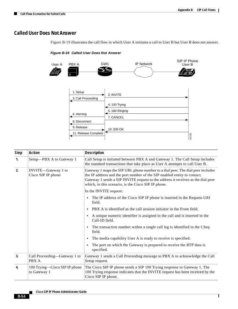
Appendix B SIP Call FlowsCall Flow Scenarios for Failed Calls
Called User Does Not Answer
Figure B-19 illustrates the call flow in which User A initiates a call to User B but User B does not answer.
Figure B-19 Called User Does Not Answer
Step Action Description
1. Setup—PBX A to Gateway 1 Call Setup is initiated between PBX A and Gateway 1. The Call Setup includes the standard transactions that take place as User A attempts to call User B.
2. INVITE—Gateway 1 to Cisco SIP IP phone
Gateway 1 maps the SIP URL phone number to a dial peer. The dial peer includes the IP address and the port number of the SIP enabled entity to contact. Gateway 1 sends a SIP INVITE request to the address it receives as the dial peer which, in this scenario, is the Cisco SIP IP phone.
In the INVITE request:
• The IP address of the Cisco SIP IP phone is inserted in the Request-URI field.
• PBX A is identified as the call session initiator in the From field.
• A unique numeric identifier is assigned to the call and is inserted in the Call-ID field.
• The transaction number within a single call leg is identified in the CSeq field.
• The media capability User A is ready to receive is specified.
• The port on which the Gateway is prepared to receive the RTP data is specified.
3. Call Proceeding—Gateway 1 to PBX A
Gateway 1 sends a Call Proceeding message to PBX A to acknowledge the Call Setup request.
4. 100 Trying—Cisco SIP IP phone to Gateway 1
The Cisco SIP IP phone sends a SIP 100 Trying response to Gateway 1. The 100 Trying response indicates that the INVITE request has been received by the Cisco SIP IP phone.
IP
SIP IP PhoneUser B
3. Call Proceeding
11. Release Complete
8. Disconnect
6. Alerting
1. Setup
PBX AUser A GW1 IP Network
4. 100 Trying
10. 200 OK
5. 180 Ringing
7. CANCEL
2. INVITE
9. Release
4172
6
B-54Cisco SIP IP Phone Administrator Guide
Appendix B SIP Call FlowsCall Flow Scenarios for Failed Calls
5. 180 Ringing—Cisco SIP IP phone to Gateway 1
The Cisco SIP IP phone sends a SIP 180 Ringing response to Gateway 1. The 180 Ringing response indicates that the user is being alerted.
6. Alerting—Gateway 1 to PBX A Gateway 1 sends an Alert message to PBX A.
7. CANCEL (Ring Timeout)—Gateway 1 toCisco SIP IP phone
Because Gateway 1 did not return an appropriate response within the time allocated in the INVITE request, Gateway 1 sends a SIP CANCEL request to Gateway 2. A CANCEL request cancels a pending request with the same Call-ID, To, From, and CSeq header field values.
8. Disconnect—Gateway 1 to PBX A
Gateway 1 sends a Disconnect message to PBX A.
9. Release Complete—Gateway 1 to PBX A
Gateway 1 sends a Release Complete message to PBX A and the call session attempt is terminated.
10. 200 OK—Cisco SIP IP phone to Gateway 1
The Cisco SIP IP phone sends a SIP 200 OK response to Gateway 1. The 200 OK response confirms that User A has received the 486 Busy Here response. The call session attempt is now being terminated.
11. Release Complete—Gateway 1 to PBX A
Gateway 1 sends a Release Complete message to PBX A and the call session is terminated.
Step Action Description
B-55Cisco SIP IP Phone Administrator Guide
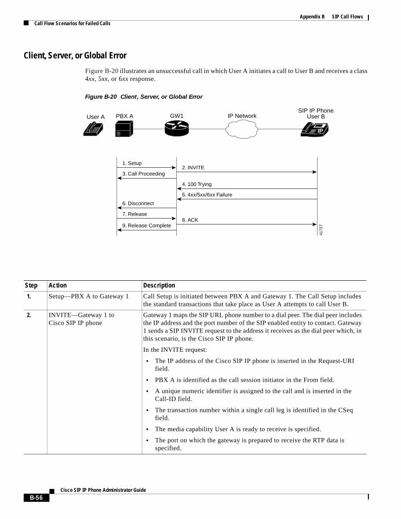
Appendix B SIP Call FlowsCall Flow Scenarios for Failed Calls
Client, Server, or Global Error
Figure B-20 illustrates an unsuccessful call in which User A initiates a call to User B and receives a class 4xx, 5xx, or 6xx response.
Figure B-20 Client, Server, or Global Error
Step Action Description
1. Setup—PBX A to Gateway 1 Call Setup is initiated between PBX A and Gateway 1. The Call Setup includes the standard transactions that take place as User A attempts to call User B.
2. INVITE—Gateway 1 to Cisco SIP IP phone
Gateway 1 maps the SIP URL phone number to a dial peer. The dial peer includes the IP address and the port number of the SIP enabled entity to contact. Gateway 1 sends a SIP INVITE request to the address it receives as the dial peer which, in this scenario, is the Cisco SIP IP phone.
In the INVITE request:
• The IP address of the Cisco SIP IP phone is inserted in the Request-URI field.
• PBX A is identified as the call session initiator in the From field.
• A unique numeric identifier is assigned to the call and is inserted in the Call-ID field.
• The transaction number within a single call leg is identified in the CSeq field.
• The media capability User A is ready to receive is specified.
• The port on which the gateway is prepared to receive the RTP data is specified.
IP
SIP IP PhoneUser B
3. Call Proceeding
6. Disconnect
1. Setup
PBX AUser A GW1 IP Network
4. 100 Trying
5. 4xx/5xx/6xx Failure
8. ACK
2. INVITE
9. Release Complete
7. Release
4172
7
B-56Cisco SIP IP Phone Administrator Guide
Appendix B SIP Call FlowsCall Flow Scenarios for Failed Calls
Cisco SIP IP Phone to Cisco SIP IP PhoneThe following scenarios are Cisco SIP IP phone to Cisco SIP IP phone:
• Called User Is Busy, page B-58
• Called User Does Not Answer, page B-59
• Authentication Error, page B-60
3. Call Proceeding—Gateway 1 to PBX A
Gateway 1 sends a Call Proceeding message to PBX A to acknowledge the Call Setup request.
4. 100 Trying—Cisco SIP IP phone to Gateway 1
The Cisco SIP IP phone sends a SIP 100 Trying response to Gateway 1. The 100 Trying response indicates that the INVITE request has been received by the Cisco SIP IP phone.
5. 4xx/5xx/6xx Failure—Cisco SIP IP phone to Gateway 1
The Cisco SIP IP phone sends a class 4xx, 5xx, or class 6xx failure response to Gateway 1. Depending on which class the failure response is, the call actions differ.
If the Cisco SIP IP phone sends a class 4xx failure response (a definite failure response that is a client error), the request will not be retried without modification.
If the Cisco SIP IP phone sends a class 5xx failure response (an indefinite failure that is a server error), the request is not terminated but rather other possible locations are tried.
If the Cisco SIP IP phone sends a class 6xx failure response (a global error), the search for User B is terminated because the 6xx response indicates that a server has definite information about User B, but not for the particular instance indicated in the Request-URI field. Therefore, all further searches for this user will fail.
6. Disconnect—Gateway 1 toPBX A
Gateway 1 sends a Release message to PBX A.
7. Release—PBX A to Gateway 1 PBX A sends a Release message to Gateway 1.
8. ACK—Gateway 1 to Cisco SIP IP phone
Gateway 1 sends a SIP ACK to the Cisco SIP IP phone. The ACK confirms that User A has received the 486 Busy Here response. The call session attempt is now being terminated.
9. Release Complete—Gateway 1 to PBX A
Gateway 1 sends a Release Complete message to PBX A and the call session attempt is terminated.
Step Action Description
B-57Cisco SIP IP Phone Administrator Guide
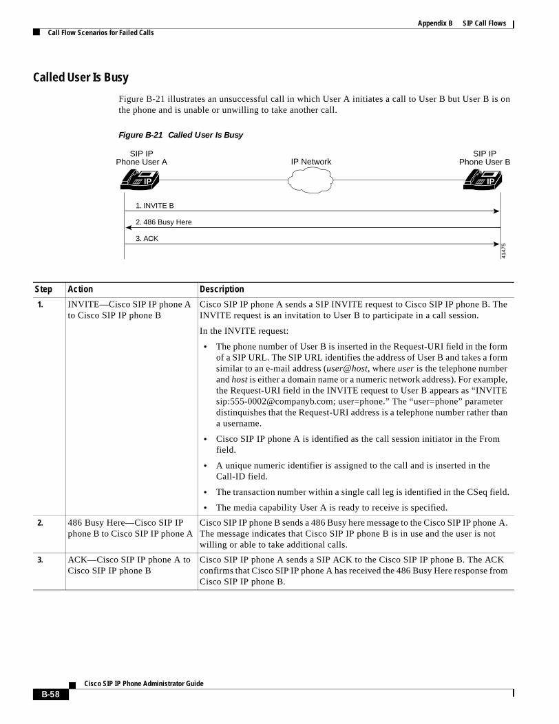
Appendix B SIP Call FlowsCall Flow Scenarios for Failed Calls
Called User Is Busy
Figure B-21 illustrates an unsuccessful call in which User A initiates a call to User B but User B is on the phone and is unable or unwilling to take another call.
Figure B-21 Called User Is Busy
Step Action Description
1. INVITE—Cisco SIP IP phone A to Cisco SIP IP phone B
Cisco SIP IP phone A sends a SIP INVITE request to Cisco SIP IP phone B. The INVITE request is an invitation to User B to participate in a call session.
In the INVITE request:
• The phone number of User B is inserted in the Request-URI field in the form of a SIP URL. The SIP URL identifies the address of User B and takes a form similar to an e-mail address (user@host, where user is the telephone number and host is either a domain name or a numeric network address). For example, the Request-URI field in the INVITE request to User B appears as “INVITE sip:[email protected]; user=phone.” The “user=phone” parameter distinquishes that the Request-URI address is a telephone number rather than a username.
• Cisco SIP IP phone A is identified as the call session initiator in the From field.
• A unique numeric identifier is assigned to the call and is inserted in the Call-ID field.
• The transaction number within a single call leg is identified in the CSeq field.
• The media capability User A is ready to receive is specified.
2. 486 Busy Here—Cisco SIP IP phone B to Cisco SIP IP phone A
Cisco SIP IP phone B sends a 486 Busy here message to the Cisco SIP IP phone A. The message indicates that Cisco SIP IP phone B is in use and the user is not willing or able to take additional calls.
3. ACK—Cisco SIP IP phone A to Cisco SIP IP phone B
Cisco SIP IP phone A sends a SIP ACK to the Cisco SIP IP phone B. The ACK confirms that Cisco SIP IP phone A has received the 486 Busy Here response from Cisco SIP IP phone B.
IP IP
2. 486 Busy Here
3. ACK
1. INVITE B
IP NetworkSIP IP
Phone User ASIP IP
Phone User B
4147
5
B-58Cisco SIP IP Phone Administrator Guide
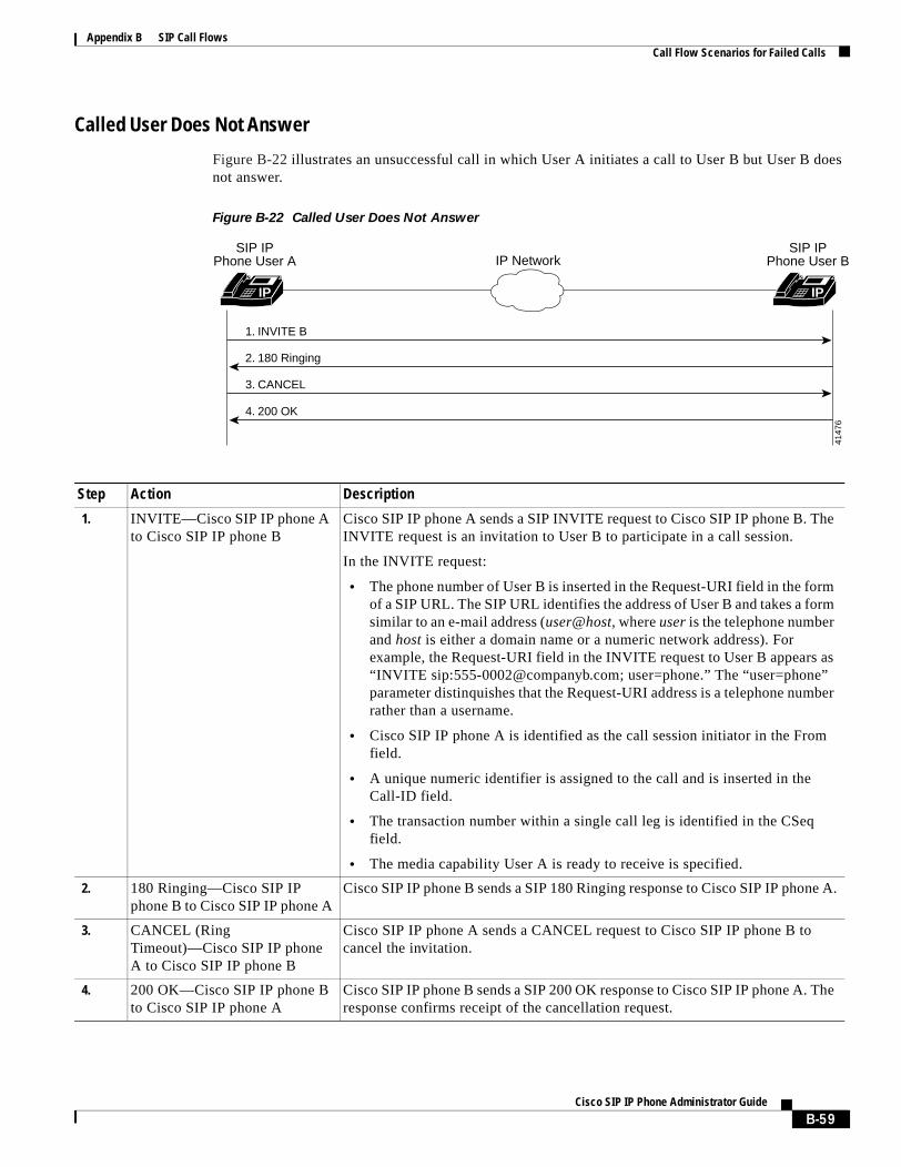
Appendix B SIP Call FlowsCall Flow Scenarios for Failed Calls
Called User Does Not Answer
Figure B-22 illustrates an unsuccessful call in which User A initiates a call to User B but User B does not answer.
Figure B-22 Called User Does Not Answer
Step Action Description
1. INVITE—Cisco SIP IP phone A to Cisco SIP IP phone B
Cisco SIP IP phone A sends a SIP INVITE request to Cisco SIP IP phone B. The INVITE request is an invitation to User B to participate in a call session.
In the INVITE request:
• The phone number of User B is inserted in the Request-URI field in the form of a SIP URL. The SIP URL identifies the address of User B and takes a form similar to an e-mail address (user@host, where user is the telephone number and host is either a domain name or a numeric network address). For example, the Request-URI field in the INVITE request to User B appears as “INVITE sip:[email protected]; user=phone.” The “user=phone” parameter distinquishes that the Request-URI address is a telephone number rather than a username.
• Cisco SIP IP phone A is identified as the call session initiator in the From field.
• A unique numeric identifier is assigned to the call and is inserted in the Call-ID field.
• The transaction number within a single call leg is identified in the CSeq field.
• The media capability User A is ready to receive is specified.
2. 180 Ringing—Cisco SIP IP phone B to Cisco SIP IP phone A
Cisco SIP IP phone B sends a SIP 180 Ringing response to Cisco SIP IP phone A.
3. CANCEL (Ring Timeout)—Cisco SIP IP phone A to Cisco SIP IP phone B
Cisco SIP IP phone A sends a CANCEL request to Cisco SIP IP phone B to cancel the invitation.
4. 200 OK—Cisco SIP IP phone B to Cisco SIP IP phone A
Cisco SIP IP phone B sends a SIP 200 OK response to Cisco SIP IP phone A. The response confirms receipt of the cancellation request.
IP IP
2. 180 Ringing
4. 200 OK
3. CANCEL
1. INVITE B
IP NetworkSIP IP
Phone User ASIP IP
Phone User B
4147
6
B-59Cisco SIP IP Phone Administrator Guide
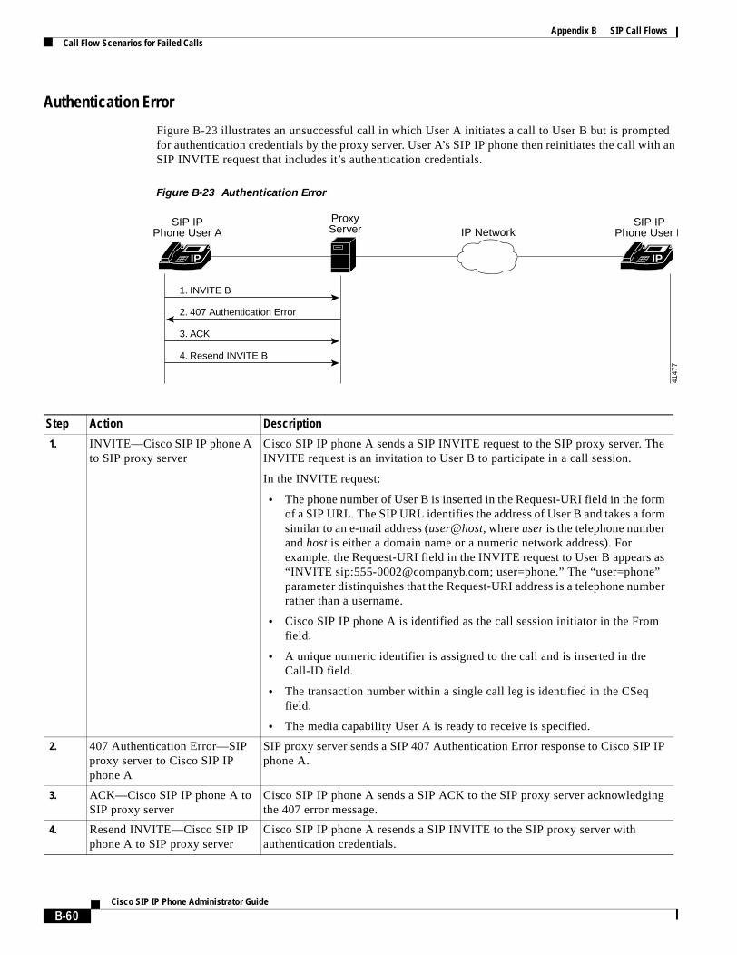
Appendix B SIP Call FlowsCall Flow Scenarios for Failed Calls
Authentication Error
Figure B-23 illustrates an unsuccessful call in which User A initiates a call to User B but is prompted for authentication credentials by the proxy server. User A’s SIP IP phone then reinitiates the call with an SIP INVITE request that includes it’s authentication credentials.
Figure B-23 Authentication Error
Step Action Description
1. INVITE—Cisco SIP IP phone A to SIP proxy server
Cisco SIP IP phone A sends a SIP INVITE request to the SIP proxy server. The INVITE request is an invitation to User B to participate in a call session.
In the INVITE request:
• The phone number of User B is inserted in the Request-URI field in the form of a SIP URL. The SIP URL identifies the address of User B and takes a form similar to an e-mail address (user@host, where user is the telephone number and host is either a domain name or a numeric network address). For example, the Request-URI field in the INVITE request to User B appears as “INVITE sip:[email protected]; user=phone.” The “user=phone” parameter distinquishes that the Request-URI address is a telephone number rather than a username.
• Cisco SIP IP phone A is identified as the call session initiator in the From field.
• A unique numeric identifier is assigned to the call and is inserted in the Call-ID field.
• The transaction number within a single call leg is identified in the CSeq field.
• The media capability User A is ready to receive is specified.
2. 407 Authentication Error—SIP proxy server to Cisco SIP IP phone A
SIP proxy server sends a SIP 407 Authentication Error response to Cisco SIP IP phone A.
3. ACK—Cisco SIP IP phone A to SIP proxy server
Cisco SIP IP phone A sends a SIP ACK to the SIP proxy server acknowledging the 407 error message.
4. Resend INVITE—Cisco SIP IP phone A to SIP proxy server
Cisco SIP IP phone A resends a SIP INVITE to the SIP proxy server with authentication credentials.
ProxyServer
IP IP
2. 407 Authentication Error
4. Resend INVITE B
3. ACK
1. INVITE B
IP NetworkSIP IP
Phone User ASIP IP
Phone User B
4147
7
B-60Cisco SIP IP Phone Administrator Guide

Appendix B SIP Call FlowsCall Flow Scenarios for Failed Calls
B-61Cisco SIP IP Phone Administrator Guide

Appendix B SIP Call FlowsCall Flow Scenarios for Failed Calls
B-62Cisco SIP IP Phone Administrator Guide
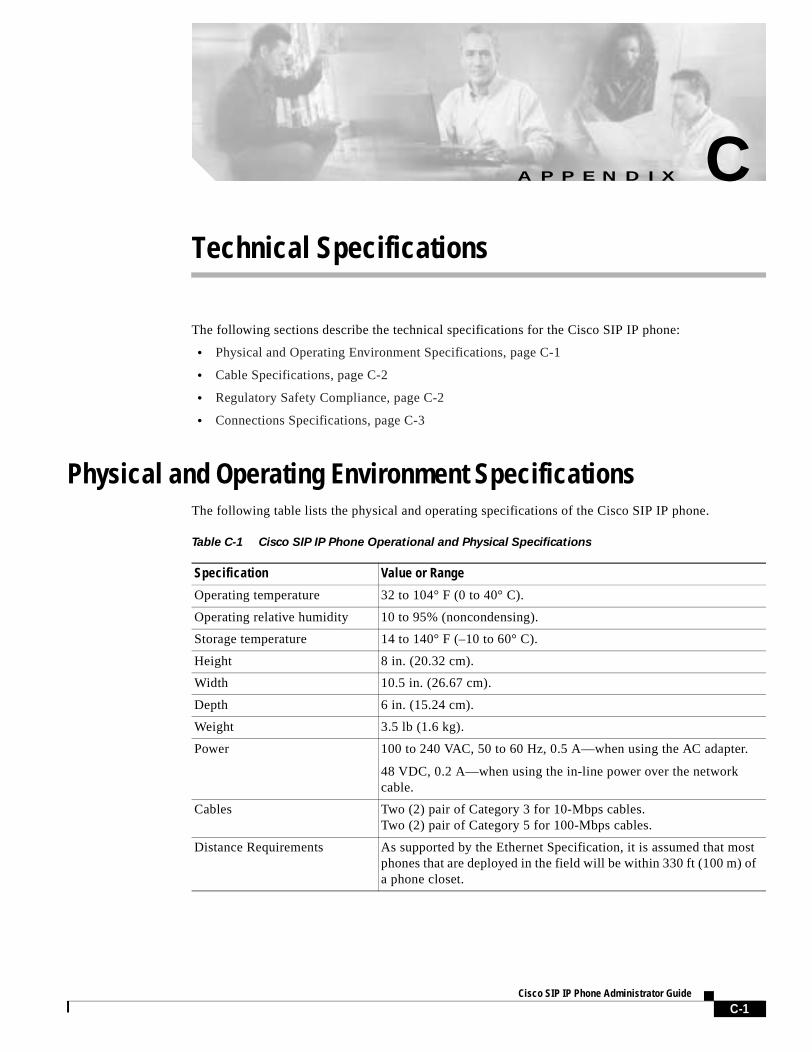
A P P E N D I X C
Technical SpecificationsThe following sections describe the technical specifications for the Cisco SIP IP phone:
• Physical and Operating Environment Specifications, page C-1
• Cable Specifications, page C-2
• Regulatory Safety Compliance, page C-2
• Connections Specifications, page C-3
Physical and Operating Environment SpecificationsThe following table lists the physical and operating specifications of the Cisco SIP IP phone.
Table C-1 Cisco SIP IP Phone Operational and Physical Specifications
Specification Value or Range
Operating temperature 32 to 104° F (0 to 40° C).
Operating relative humidity 10 to 95% (noncondensing).
Storage temperature 14 to 140° F (–10 to 60° C).
Height 8 in. (20.32 cm).
Width 10.5 in. (26.67 cm).
Depth 6 in. (15.24 cm).
Weight 3.5 lb (1.6 kg).
Power 100 to 240 VAC, 50 to 60 Hz, 0.5 A—when using the AC adapter.
48 VDC, 0.2 A—when using the in-line power over the network cable.
Cables Two (2) pair of Category 3 for 10-Mbps cables.Two (2) pair of Category 5 for 100-Mbps cables.
Distance Requirements As supported by the Ethernet Specification, it is assumed that most phones that are deployed in the field will be within 330 ft (100 m) of a phone closet.
C-1Cisco SIP IP Phone Administrator Guide
Appendix C Technical SpecificationsCable Specifications
Cable SpecificationsThe following cables are required to connect the Cisco SIP IP phone:
• RJ-11 for the handset connection.
• RJ-45 jack for the LAN connection (labeled “10/100 SW”).
• RJ-45 jack for a second 10BASE-T compliant connection (labeled “10/100 PC”).
• 48-volt power connector. The diameter of the center pin in the phone power jack (Switchcraft 712A) is 0.1 in (2.5 mm). The center pin is positive (+) voltage. The miniature power plug required to mate with the power jack on the phone is a Switchcraft 760 or equivalent.
Regulatory Safety ComplianceThe Cisco IP Phone 7960, 7940, and 7910 meet the following regulatory safety and compliance approvals:
• CE Marking
• Safety
– UL1950
– CSA C22.2 No. 950
– EN 60950
– IEC 60950
– AS/NZS 3260
– TS001
• EMC
– AS/NZS 3548 Class B
– VCCI Class B
– FCC (47 CFR) Part 15 Class B
– EN 55022, Class B
• Telecom
– IC CS-03
– FCC (47 CFR) Part 68
Figure C-1 contains the FCC Class B Declaration for the Cisco IP Phone 7960, 7940, 7910, and 7910+SW.
C-2Cisco SIP IP Phone Administrator Guide
Appendix C Technical SpecificationsConnections Specifications
Figure C-1 FCC Class B Declaration
Connections SpecificationsThe Cisco SIP IP phone has two RJ-45 ports that each support 10/100 Mbps half- or full-duplex connections to external devices—the network port and access port. You can use either Category 3 or 5 cabling for 10 Mpbs connections, but use Category 5 for 100 Mbps connections. On both the LAN-to-phone port (left RJ-45 port facing the back of the phone) and PC-to-phone port (right port), use full-duplex to avoid collisions. Use the LAN-to-phone port to connect the phone to the network a LAN-to-phone jack. Use the PC-to-phone port to connect a network device, such as a computer, to the phone.
For a diagram identifying the different ports on the back of the Cisco SIP IP phone, see the “Installing the Cisco SIP IP Phone” section on page 2-2.
C-3Cisco SIP IP Phone Administrator Guide

Appendix C Technical SpecificationsConnections Specifications
C-4Cisco SIP IP Phone Administrator Guide
A P P E N D I X D
Translated Safety WarningsThis appendix contains in multiple languages the warnings that should be used with the “Getting Started with Your Cisco SIP IP Phone” chapter of this guide.
Installation Warning
Warning Read the installation instructions before you connect the system to its power source.
Waarschuwing Raadpleeg de installatie-aanwijzingen voordat u het systeem met de voeding verbindt.
Varoitus Lue asennusohjeet ennen järjestelmän yhdistämistä virtalähteeseen.
Attention Avant de brancher le système sur la source d'alimentation, consulter les directives d'installation.
Warnung Lesen Sie die Installationsanweisungen, bevor Sie das System an die Stromquelle anschließen.
Avvertenza Consultare le istruzioni di installazione prima di collegare il sistema all'alimentatore.
Advarsel Les installasjonsinstruksjonene før systemet kobles til strømkilden.
Aviso Leia as instruções de instalação antes de ligar o sistema à sua fonte de energia.
¡Advertencia! Ver las instrucciones de instalación antes de conectar el sistema a la red de alimentación.
Varning! Läs installationsanvisningarna innan du kopplar systemet till dess strömförsörjningsenhet.
Product Disposal Warning
Warning Ultimate disposal of this product should be handled according to all national laws and regulations.
Waarschuwing Dit produkt dient volgens alle landelijke wetten en voorschriften te worden afgedankt.
Varoitus Tämän tuotteen lopullisesta hävittämisestä tulee huolehtia kaikkia valtakunnallisia lakeja ja säännöksiä noudattaen.
Attention La mise au rebut définitive de ce produit doit être effectuée conformément à toutes les lois et réglementations en vigueur.
Warnung Dieses Produkt muß den geltenden Gesetzen und Vorschriften entsprechend entsorgt werden.
D-1Cisco SIP IP Phone Administrator Guide
Appendix D Translated Safety WarningsLightning Activity Warning
Avvertenza L'eliminazione finale di questo prodotto deve essere eseguita osservando le normative italiane vigenti in materia.
Advarsel Endelig disponering av dette produktet må skje i henhold til nasjonale lover og forskrifter.
Aviso A descartagem final deste produto deverá ser efectuada de acordo com os regulamentos e a legislação nacional.
¡Advertencia! El desecho final de este producto debe realizarse según todas las leyes y regulaciones nacionales.
Varning! Slutlig kassering av denna produkt bör skötas i enlighet med landets alla lagar och föreskrifter.
Lightning Activity Warning
Warning Do not work on the system or connect or disconnect cables during periods of lightning activity.
Waarschuwing Tijdens onweer dat gepaard gaat met bliksem, dient u niet aan het systeem te werken of kabels aan te sluiten of teontkoppelen.
Varoitus Älä työskentele järjestelmän parissa äläkä yhdistä tai irrota kaapeleita ukkosilmalla.
Attention Ne pas travailler sur le système ni brancher ou débrancher les câbles pendant un orage du foudre.
Warnung Arbeiten Sie nicht am System und schließen Sie keine Kabel an bzw. trennen Sie keine ab, wenn es gewittert.
Avvertenza Non lavorare sul sistema o collegare oppure scollegare i cavi durante un temporale con fulmini.
Advarsel Utfør aldri arbeid på systemet, eller koble kabler til eller fra systemet når det tordner eller lyner.
Aviso Não trabalhe no sistema ou ligue e desligue cabos durante períodos de mau tempo (trovoada).
¡Advertencia! No operar el sistema ni conectar o desconectar cables durante el transcurso de descargas eléctricas en la atmósfera.
Varning! Vid åska skall du aldrig utföra arbete på systemet eller ansluta eller koppla loss kablar.
SELV Circuit Warning
Warning To avoid electric shock, do not connect safety extra-low voltage (SELV) circuits to telephone-network voltage (TNV) circuits. LAN ports contain SELV circuits, and WAN ports contain TNV circuits. Some LAN and WAN ports both use RJ-45 connectors. Use caution when connecting cables.
Waarschuwing Om elektrische schokken te vermijden, mogen veiligheidscircuits met extra lage spanning (genaamd SELV = Safety Extra-Low Voltage) niet met telefoonnetwerkspanning (TNV) circuits verbonden worden. LAN (Lokaal netwerk) poorten bevatten SELV circuits en WAN (Regionaal netwerk) poorten bevatten TNV circuits. Sommige LAN en WAN poorten gebruiken allebei RJ-45 connectors. Ga voorzichtig te werk wanneer u kabels verbindt.
D-2Cisco SIP IP Phone Administrator Guide
Appendix D Translated Safety WarningsCircuit Breaker (15A) Warning
Varoitus Jotta vältyt sähköiskulta, älä kytke pienjännitteisiä SELV-suojapiirejä puhelinverkkojännitettä (TNV) käyttäviin virtapiireihin. LAN-portit sisältävät SELV-piirejä ja WAN-portit puhelinverkkojännitettä käyttäviä piirejä. Osa sekä LAN- että WAN-porteista käyttää RJ-45-liittimiä. Ole varovainen kytkiessäsi kaapeleita.
Attention Pour éviter une électrocution, ne raccordez pas les circuits de sécurité basse tension (Safety Extra-Low Voltage ou SELV) à des circuits de tension de réseau téléphonique (Telephone Network Voltage ou TNV). Les ports du réseau local (LAN) contiennent des circuits SELV et les ports du réseau longue distance (WAN) sont munis de circuits TNV. Certains ports LAN et WAN utilisent des connecteurs RJ-45. Raccordez les câbles en prenant toutes les précautions nécessaires.
Warnung Zur Vermeidung von Elektroschock die Sicherheits-Kleinspannungs-Stromkreise (SELV-Kreise) nicht an Fernsprechnetzspannungs-Stromkreise (TNV-Kreise) anschließen. LAN-Ports enthalten SELV-Kreise, und WAN-Ports enthalten TNV-Kreise. Einige LAN- und WAN-Ports verwenden auch RJ-45-Steckverbinder. Vorsicht beim Anschließen von Kabeln.
Avvertenza Per evitare scosse elettriche, non collegare circuiti di sicurezza a tensione molto bassa (SELV) ai circuiti a tensione di rete telefonica (TNV). Le porte LAN contengono circuiti SELV e le porte WAN contengono circuiti TNV. Alcune porte LAN e WAN fanno uso di connettori RJ-45. Fare attenzione quando si collegano cavi.
Advarsel Unngå å koble lavspenningskretser (SELV) til kretser for telenettspenning (TNV), slik at du unngår elektrisk støt. LAN-utganger inneholder SELV-kretser og WAN-utganger inneholder TNV-kretser. Det finnes både LAN-utganger og WAN-utganger som bruker RJ-45-kontakter. Vær forsiktig når du kobler kabler.
Aviso Para evitar choques eléctricos, não conecte os circuitos de segurança de baixa tensão (SELV) aos circuitos de tensão de rede telefónica (TNV). As portas LAN contêm circuitos SELV e as portas WAN contêm circuitos TNV. Algumas portas LAN e WAN usam conectores RJ-45. Tenha o devido cuidado ao conectar os cabos.
¡Advertencia! Para evitar la sacudida eléctrica, no conectar circuitos de seguridad de voltaje muy bajo (safety extra-low voltage = SELV) con circuitos de voltaje de red telefónica (telephone network voltage = TNV). Los puertos de redes de área local (local area network = LAN) contienen circuitos SELV, y los puertos de redes de área extendida (wide area network = WAN) contienen circuitos TNV. En algunos casos, tanto los puertos LAN como los WAN usan conectores RJ-45. Proceda con precaución al conectar los cables.
Varning! För att undvika elektriska stötar, koppla inte säkerhetskretsar med extra låg spänning (SELV-kretsar) till kretsar med telefonnätspänning (TNV-kretsar). LAN-portar innehåller SELV-kretsar och WAN-portar innehåller TNV-kretsar. Vissa LAN- och WAN-portar är försedda med RJ-45-kontakter. Iaktta försiktighet vid anslutning av kablar.
Circuit Breaker (15A) Warning
Warning This product relies on the building’s installation for short-circuit (overcurrent) protection. Ensure that a fuse or circuit breaker no larger than 120 VAC, 15 A U.S. (240 VAC, 10 A international) is used on the phase conductors (all current-carrying conductors).
Waarschuwing Dit produkt is afhankelijk van de installatie van het gebouw voor kortsluit- (overstroom)beveiliging. Controleer of er een zekering of stroomverbreker van niet meer dan 120 Volt wisselstroom, 15 A voor de V.S. (240 Volt wisselstroom, 10 A internationaal) gebruikt wordt op de fasegeleiders (alle geleiders die stroom voeren).
D-3Cisco SIP IP Phone Administrator Guide
Appendix D Translated Safety WarningsCircuit Breaker (15A) Warning
Varoitus Tämä tuote on riippuvainen rakennukseen asennetusta oikosulkusuojauksesta (ylivirtasuojauksesta). Varmista, että vaihevirtajohtimissa (kaikissa virroitetuissa johtimissa) käytetään Yhdysvalloissa alle 120 voltin, 15 ampeerin ja monissa muissa maissa 240 voltin, 10 ampeerin sulaketta tai suojakytkintä.
Attention Pour ce qui est de la protection contre les courts-circuits (surtension), ce produit dépend de l'installation électrique du local. Vérifier qu'un fusible ou qu'un disjoncteur de 120 V alt., 15 A U.S. maximum (240 V alt., 10 A international) est utilisé sur les conducteurs de phase (conducteurs de charge).
Warnung Dieses Produkt ist darauf angewiesen, daß im Gebäude ein Kurzschluß- bzw. Überstromschutz installiert ist. Stellen Sie sicher, daß eine Sicherung oder ein Unterbrecher von nicht mehr als 240 V Wechselstrom, 10 A (bzw. in den USA 120 V Wechselstrom, 15 A) an den Phasenleitern (allen stromführenden Leitern) verwendet wird.
Avvertenza Questo prodotto dipende dall’installazione dell’edificio per quanto riguarda la protezione contro cortocircuiti (sovracorrente). Verificare che un fusibile o interruttore automatico, non superiore a 120 VCA, 15 A U.S. (240 VCA, 10 A internazionale) sia stato usato nei fili di fase (tutti i conduttori portatori di corrente).
Advarsel Dette produktet er avhengig av bygningens installasjoner av kortslutningsbeskyttelse (overstrøm). Kontroller at det brukes en sikring eller strømbryter som ikke er større enn 120 VAC, 15 A (USA) (240 VAC, 10 A internasjonalt) på faselederne (alle strømførende ledere).
Aviso Este produto depende das instalações existentes para protecção contra curto-circuito (sobrecarga). Assegure-se de que um fusível ou disjuntor não superior a 240 VAC, 10A é utilizado nos condutores de fase (todos os condutores de transporte de corrente).
¡Advertencia! Este equipo utiliza el sistema de protección contra cortocircuitos (o sobrecorrientes) deló propio edificio. Asegurarse de que se utiliza un fusible o interruptor automático de no más de 240 voltios en corriente alterna (VAC), 10 amperios del estándar internacional (120 VAC, 15 amperios del estándar USA) en los hilos de fase (todos aquéllos portadores de corriente).
Varning! Denna produkt är beroende av i byggnaden installerat kortslutningsskydd (överströmsskydd). Kontrollera att säkring eller överspänningsskydd används på fasledarna (samtliga strömförande ledare) ¥ för internationellt bruk max. 240 V växelström, 10 A (iþUSA max. 120 V växelström, 15 A).
D-4Cisco SIP IP Phone Administrator Guide
Ci
G L O S S A R Y
A
AAA Authentication, authorization, and accounting. AAA is a suite of network security services that provides the primary framework through which access control can be set up on your Cisco router or access server.
ANI Automatic number identification.
B
BTXML Basic telephony extensible markup language
C
CAS Channel-associated signaling.
CCAPI Call control applications programming interface.
CLI Command-line interface.
CO Central office.
CPE Customer premises equipment. Terminating equipment, such as terminals, telephones, and modems, supplied by the telephone company, installed at the customer sites, and connected to the telephone company network.
CSM Call switching module.
D
dial peer An addressable call endpoint. In Voice over IP (VoIP), there are two types of dial peers: POTS and VoIP.
DNS Domain Name System. Used to address translation to convert H.323 IDs, URLs, or e-mail IDs to IP addresses. DNS is also used to assist in the locating remote gatekeepers and to reverse-map raw IP addresses to host names of administrative domains.
DNIS Dialed number identification service (the called number)
GL-1sco SIP IP Phone Administrator Guide
Glossary
DSP Digital signal processor.
DTMF Dual tone multifrequency.
E
E.164 The international public telecommunications numbering plan. A standard set by ITU-T which addresses telephone numbers.
E&M Ear and mouth RBS signaling.
endpoint A SIP terminal or gateway. An endpoint can call and be called. It generates and/or terminates the information stream.
G
gateway A gateway allows SIP or H.323 terminals to communicate with terminals configured to other protocols by converting protocols. A gateway is the point where a circuit-switched call is encoded and repackaged into IP packets.
H
H.323 An International Telecommunication Union (ITU-T) standard that describes packet-based video, audio, and data conferencing. H.323 is an umbrella standard that describes the architecture of the conferencing system and refers to a set of other standards (H.245, H.225.0, and Q.931) to describe its actual protocol.
H.323 RAS Registration, admission, and status. The RAS signaling function performs registration, admissions, bandwidth changes, status and disengage procedures between the VoIP gateway and the gatekeeper.
I
IVR Interactive voice response. When someone dials in, IVR responds with a prompt to get a personal identification number (PIN), and so on.
L
LEC Local exchange carrier.
location server A SIP redirect or proxy server uses a a location service to get information about a caller’s locations. Location services are offered by location servers.
GL-2Cisco SIP IP Phone Administrator Guide
Glossary
M
MF Multifrequency tones are made of six frequencies that provide 15 two frequency combinations for indication digits 0-9 and KP/ST signals.
multicast A process of transmitting protocol data units (PDUs) from one source to many destinations. The actual mechanism (that is, IP multicast, multiunicast, and so forth) for this process might be different for LAN technologies.
multipoint-unicast A process of transferring PDUs where an endpoint sends more than one copy of a media stream to different endpoints. This can be necessary in networks that do not support multicast.
N
node A H.323 entity that uses RAS to communicate with the gatekeeper; for example, an endpoint such as a terminal, proxy, or gateway.
P
PDU Protocol data units used by bridges to transfer connectivity information.
POTS Plain old telephone service. Basic telephone service supplying standard single line telephones, telephone lines, and access to the PSTN.
proxy server An intermediary program that acts as both a server and a client for the purpose of making requests on behalf of other clients. Requests are serviced internally or by passing them on, possibly after translation, to other servers. A proxy interprets, and, if necessary, rewrites a request message before forwarding it.
PSTN Public switched telephone network. PSTN refers to the local telephone company.
R
redirect server A redirect server is a server that accepts a SIP request, maps the address into zero or more new addresses and returns these addresses to the client. It does not initiate its own SIP request nor accept calls.
registrar A registrar is a server that accepts REGISTER requests. A registrar is typically colocated with a proxy or redirect server and may offer location services.
RAS Registration, admission, and status protocol. This is the protocol that is used between endpoints and the gatekeeper to perform management functions.
RBS Robbed-bit signaling.
GL-3Cisco SIP IP Phone Administrator Guide
Glossary
S
SIP Session Initiation Protocol. This is a protocol developed by the IETF MMUSIC Working Group as an alternative to H.323. SIP features are compliant with IETF RFC 2543, published in March 1999.
SIP equips platforms to signal the setup of voice and multimedia calls over IP networks.
SPI Service provider interface.
T
TDM Time-division multiplexing. Technique in which information from multiple channels can be allocated bandwidth on a single wire, based on preassigned time slots. Bandwidth is allocated to each channel regardless of whether the station has data to transmit.
U
user agent See UAS.
UAC User agent client. A user agent client is a client application that initiates the SIP request.
UAS User agent server (or user agent). A user agent server is a server application that contacts the user when a SIP request is received, then returns a response on behalf of the user. The response accepts, rejects, or redirects the request.
V
VoIP Voice over IP. The ability to carry normal telephone-style voice over an IP-based Internet with POTs-like functionality, reliability, and voice quality. VoIP is a blanket term, that generally refers to the Cisco standards-based (for example H.323) approach to IP voice traffic.
GL-4Cisco SIP IP Phone Administrator Guide
Cisco
I N D E X
Numerics
10/100 PC port 1-13
10/100 SW port 1-13
1xx responses A-2
2xx responses A-3
3xx responses A-3
4xx responses A-4
5xx responses A-6
6xx responses A-7
A
abbreviations, time zone 3-37
Accept-Encoding header field A-7
Accept header field A-7
Accept-Language header field A-7
accessing
firmware version 3-44
network statistics 3-43
status messages 3-42
access port 1-13
address
proxy server 3-27
TFTP server 3-6
adjusting, phone placement 2-12
administrative VLAN ID parameter 3-4
Allow header field A-7
Also header field A-7
alternate TFTP server, enabling 3-4
authentication
name, configuring 3-24
services 1-2
Authorization header field A-7
B
basic telephony extensible markup language (BTXML) 1-5
billing services 1-2
book
objectives viii
organization viii
BTXML 1-5
buttons
information 1-4
line 1-4
volume 1-4
C
cables
connecting 2-11
specifications C-2
Caller ID blocking 1-8
call flows B-1
successful B-1
unsuccessful B-52
call forward 1-8
call hold 1-8
Call-ID header field A-7
call preferences menu 3-6
call transfer 1-8
call waiting disabled 1-8
call waiting enabled 1-8
character support 1-10
circuit breaker (15A) warning D-3
CiscoCallManager XML 1-5
clients
gateways 1-3
IN-1 SIP IP Phone Administrator Guide
Index
phones 1-3
SIP 1-3
codec, specifying 3-17, 3-28
common parameters 3-9
compliance information A-1
configuration, erasing 3-5
configuration files
default
creating 2-5
example 3-21
modifying 3-9
guidelines 2-5
phone-specific 2-4, 2-7
creating 2-6
example 3-25
modifying 3-23
naming convention 2-5
SIPDefault.cnf 2-5
storing 2-5
configuration mode
entering into 3-2
locking 3-3
unlocking 3-2
configuring
lines
authentication name 3-24
name 3-24, 3-25
password 3-24
short name 3-25
network parameters 2-9
manually 2-10
via DHCP 2-10
SIP parameters
manually 2-7
via TFTP 2-4
connections 1-12, 2-11
Contact header field A-7
Content-Encoding header field A-7
Content-Length header field A-7
IN-2Cisco SIP IP Phone Administrator Guide
Content-Type header field A-7
conventions, document viii
Cseq header field A-7
D
Date header field A-7
daylight savings time 3-35
default configuration file 2-4, 2-5
example 2-6, 3-21
guidelines 2-5
modifying 3-9
SIPDefault.cnf 2-3
default router parameters 3-4
DHCP
description 1-11
enabling 3-4
options
default IP gateway 2-10
DNS server 2-10
domain name 2-10
IP address 2-10
IP subnet mask 2-10
TFTP server 2-10
releasing address 3-4
server parameter 3-4
dialing pad 1-4
directory services 1-2
DNS
description 1-11
server parameters 3-4
documentation
conventions viii
related x
domain name parameter 3-4
Domain Name System (DNS) 1-11
do not disturb 1-7
downloading required files 2-3
DST 3-35
Index
DTMF
DB level 3-13
inband 3-13
outofbound 3-13, 3-28
payload 3-13
Dynamic Host Control Protocol (DHCP) 1-11
E
enabling
alternate TFTP server 3-4
DHCP 3-4
registration 3-18, 3-28
Encryption header field A-7
endpoint, SIP 1-2
erasing
configuration 3-5
parameters 3-41
settings 3-41
example
default configuration file 3-21
phone-specific configuration file 3-25
Expires header field A-7
F
features
call forward 1-8
call hold 1-8
call transfer 1-8
call waiting disabled 1-8
call waiting enabled 1-8
do not disturb 1-7
secondary directory number 1-7
URL dialing 1-8
file
default 3-21
phone-specific 3-25
files
audio 2-3
dual boot 2-3
firmware image 2-3
OS79XX.txt 2-3
RINGLIST.DAT 2-3
SIPDefault.cnf 2-3
firmware
image 2-3
updating 3-44
version, viewing 3-44
footstand adjustment 1-4
From header field A-7
functions
proxy server A-1
redirect server A-1
UAC A-1
UAS A-1
G
gateways 1-3
glossary 1
guidelines 2-10
H
handset 1-4
header fields A-7
headset
supported types 1-14
using 1-14
headset and speaker toggle 1-4
Hide header field A-7
host name parameter 3-5
HTTP proxy address parameter 3-5
IN-3Cisco SIP IP Phone Administrator Guide
Index
I
ICMP, description 1-11
image version 3-15
information button 1-4
initialization process 2-1
installation 2-2
downloading required files 2-3
network parameters 2-9
safety warnings D-1, D-2
SIP parameters 2-4
task summary 2-2
Internet Control Message Protocol (ICMP) 1-11
Internet Protocol (IP) 1-11
INVITE
retransmission expiration 3-20
IP
address parameter 3-5
description 1-11
ISO 8859-1 Latin1 characters 1-10
K
keys
on-screen mode 1-4
scroll 1-4
soft 1-4
L
language support 1-10
LCD screen 1-4
line buttons 1-4
lines, configuring
authentication name 3-24
name 3-24, 3-25
password 3-24
short name 3-25
linex_authname parameter 3-24
IN-4Cisco SIP IP Phone Administrator Guide
linex_name parameter 3-24, 3-25
linex_password parameter 3-24
linex_shortname parameter 3-25
locking, configuration mode 3-3
M
MAC address parameter 3-5
Max-Forwards header field A-7
menu
call preferences 3-6
messages, status 3-42
messages URI parameter 3-28
Message Waiting Indication 1-7
methods
ACK A-2
BYE A-2
CANCEL A-2
INVITE A-2
OPTIONS A-2
REGISTER A-2
modifying
network parameters 3-2, 3-3
SIP parameters 3-9, 3-23
mute toggle 1-4
N
name, configuring 3-24, 3-25
naming convention, phone-specific configuration file 2-5
NAT 3-16
network
connections 1-13
parameters
administrative VLAN ID 3-4
alternate TFTP 3-4
configuring via DHCP 2-10
default router 3-4
Index
DHCP address release 3-4
DHCP enable 3-4
DHCP server 3-4
domain name 3-4
dynamic DNS server 3-5
dynamic TFTP server 3-5
erase configuration 3-5
guidelines 2-10
host name 3-5
HTTP proxy address 3-5
HTTP proxy port 3-5
IP address 3-5
MAC address 3-5
operational VLAN ID 3-6
subnet mask 3-6
TFTP server 3-6
port 1-13
statistics 3-43
network address translation (NAT 3-16, 3-28
network connections
access port 1-13
O
on-screen mode keys 1-4
operating environment specifications C-1
operational VLAN ID parameter 3-6
Organization header field A-7
OS79XX.txt 2-3
Out of Band DTMF parameter 3-28
overview
Cisco SIP IP phone 1-3
initialization process 2-1
product 1-1
SIP 1-1
P
parameters
common 2-5, 3-9
configuring
network 2-9
SIP 2-4
directory_url 1-5
erasing 3-41
logo_url 1-5
nat_enable 3-16
network 2-9
administrative VLAN ID 3-4
alternate TFTP 3-4
default routers 3-4
DHCP address release 3-4
DHCP enable 3-4
DHCP server 3-4
DNS server 3-4
domain name 3-4
dynamic DNS server 3-5
dynamic TFTP server 3-5
erase configuration 3-5
guidelines 2-10
host name 3-5
HTTP proxy address 3-5
HTTP proxy port 3-5
IP address 3-5
MAC address 3-5
modifying 3-2, 3-3
operational VLAN ID 3-6
subnet mask address 3-6
TFTP server 3-6
required 2-7
services_url 1-5
SIP
Authentication Name 3-27
Authentication Password 3-27
dtmf_avt_payload 3-13
IN-5Cisco SIP IP Phone Administrator Guide
Index
dtmf_db_level 3-13
dtmf_outofbound 3-13
image_version 3-15
linex_authname 3-24
linex_name 3-24, 3-25
linex_password 3-24
linex_shortname 3-25
Messages URI 3-28
Name 3-27
Out of Band DTMF 3-28
Prefered Codec 3-28
preferred_codec 3-17
proxy_register 3-18
proxy1_address 3-18
proxy1_port 3-18
Proxy Address 3-27
Proxy Port 3-27
Register Expires 3-28
Register with Proxy 3-28
required 2-6
Short Name 3-27
sip_invite_retx 3-19
sip_retx 3-19
telnet_enable 3-20
timer_invite_expires 3-20
timer_register_expires 3-20
timer_t1 3-20
timer_t2 3-20
tos_media 3-21
password
configuring 3-24
line 3-24
phone 3-9
adjusting placement 2-12
connecting 2-11
connections 1-12
access port 1-13
network 1-13
network port 1-13
IN-6Cisco SIP IP Phone Administrator Guide
features
dialing pad 1-4
footstand adjustment 1-4
handset 1-4
headset 1-14
headset and speaker toggle 1-4
information button 1-4
LCD screen 1-4
line buttons 1-4
mute toggle 1-4
on-screen mode keys 1-4
physical 1-3
scroll key 1-4
soft keys 1-4
volume buttons 1-4
installing 2-2
interfaces 1-3
mounting to wall 2-13
overview 1-3
prerequisites 1-12
secondary directory number 1-7
supported features 1-6
supported protocols 1-11
DHCP 1-11
DNS 1-11
ICMP 1-11
IP 1-11
RTP 1-11
SDP 1-11
SNTP 1-11
TCP 1-11
TFTP 1-11
UDP 1-11
URL dialing 1-8
verifying startup 2-14
phone-specific configuration file
creating 2-7
example 2-6, 3-25
modifying 3-23
Index
physical specifications C-1
port
access 1-13
network 1-13
proxy server 3-27
power source
Cisco Catalyst switches 1-13
external 1-13
prerequisites 1-12
Priority header field A-7
product
overview 1-1
product disposal warning D-1
protocols 1-11
DHCP 1-11
DNS 1-11
ICMP 1-11
IP 1-11
RTP 1-11
SDP 1-11
SNTP 1-11
TCP 1-11
TFTP 1-11
UDP 1-11
Proxy-Authenticate header field A-7
Proxy-Authorization header field A-8
proxy port
specifying 3-18
Proxy-Required header field A-8
proxy server 1-3
address 3-27
port 3-27
registration, enabling 3-18, 3-28
specifying 3-18
R
Real-Time Transport Protocol (RTP) 1-11
Record-Route header field A-8
redirect server 1-3
registrar server 1-3
registration
enabling 3-18
timer 3-20, 3-28
related documentation x
release, DHCP address 3-4
request methods B-1
Require header field A-8
resetting
network statistics 3-43
Response-Key header field A-8
responses A-2
global (6xx) A-7
information (1xx) A-2
redirection (3xx) A-3
request failure (4xx) A-4
server failure (5xx) A-6
successful (2xx) A-3
retransmission timers 3-20
Retry-After header field A-8
RFC
2131 1-11
2543 1-3
3261 1-1
768 1-11
791 1-11
792 1-11
RINGLIST.DAT 2-3
Route header field A-8
RTP, description 1-11
S
safety warnings, translated D-1
circuit breaker (15A) warning D-3
installation warning D-1
lightning activity warning D-2
product disposal warning D-1
IN-7Cisco SIP IP Phone Administrator Guide
Index
SELV circuit warning D-2
scroll key 1-4
SDP, description 1-11
SDP, usage A-8
secondary directory number 1-7
SELV circuit warning D-2
server
alternate TFTP 3-4
proxy 1-3
redirect 1-3
registrar 1-3
Server header field A-8
Session Description Protocol (SDP) 1-11
settings, erasing 3-41
short name, configuring 3-25
Simple Network Time Protocol (SNTP) 1-11
SIP
architecture 1-2
call flows B-1
successful B-1
unsuccessful B-52
clients 1-2, 1-3
gateways 1-3
phones 1-3
compliance information A-1
components 1-2
UAC 1-2
user agent server 1-2
default configuration file, example 2-6
dtmf_inband 3-13
end point 1-2
funtions A-1
gateways 1-3
header fields A-7
IP phone, overview 1-3
methods A-2
overview 1-1
parameters
Authentication Name 3-27
IN-8Cisco SIP IP Phone Administrator Guide
Authentication Password 3-27
configuring on your phone 3-26
Message URI 3-28
Name 3-27
Out of Band DTMF 3-28
phone-specific configuration file 2-4
Preferred Codec 3-28
Proxy Address 3-27
Proxy Port 3-27
Register Expires 3-28
Register with proxy 3-28
Short Name 3-27
request methods B-1
responses A-2
global (6xx) A-7
information (1xx) A-2
redirection (3xx) A-3
request failure (4xx) A-4
server failure (5xx) A-6
successful (2xx) A-3
SDP usage A-8
servers
proxy 1-3
redirect 1-3
registrar 1-3
services
authentication 1-2
billing 1-2
directory 1-2
SIPDefault.cnf 2-3, 2-5
SIP parameters 3-26
configuring on your phone 3-26
configuring via TFTP server 2-4
SNTP, description 1-11
soft keys 1-4
specifications C-1
cable C-2
connections C-3
operating environment C-1
Index
physical C-1
specifying 3-15
codec 3-17, 3-28
DTMF level 3-13
DTMF payload 3-13
DTMF signaling 3-13
image version 3-15
proxy port 3-18
proxy server 3-18
retransmission timers 3-20
TOS media 3-21
specifying out of bound 3-28
startup, verifying 2-14
statistics, network 3-43
status information
accessing 3-42, 3-43, 3-44
Subject header field A-8
subnet mask parameter 3-6
T
TCP, description 1-11
technical specifications C-1
cablet C-2
operating environment C-1
physical C-1
telnet_enable parameter 3-20
TFTP, description 1-11
TFTP server parameter 3-6
timer
registration 3-20, 3-28
retransmission 3-20
timer_t2 3-20
timers, retransmission 3-20
Timestamp header field A-8
time zone abbreviations 3-37
time zone setting
setting
time zone 3-35
toggle
headset and speaker 1-4
mute 1-4
To header field A-8
TOS media
specifying 3-21
traceroute command 3-35
translated safety warnings D-1
circuit breaker (15A) warning D-3
installation warning D-1
lightning activity warning D-2
product disposal warning D-1
SELV circuit warning D-2
Transmission Control Protocol (TCP) 1-11
Trivial File Transfer Protocol (TFTP) 1-11
U
UAC 1-2
UDP, description 1-11
unlocking, configuration mode 3-2
Unsupported header field A-8
updating
firmware 3-44
URL dialing 1-8
user
agent server 1-2
User-Agent header field A-8
User Datagram Protocol (UDP) 1-11
V
verifying startup 2-14
Via header field A-8
viewing firmware version 3-44
VLAN
administrative 3-4
operational 3-6
IN-9Cisco SIP IP Phone Administrator Guide
Index
volume
buttons 1-4
W
wall mounting
phone 2-13
Warning header field A-8
WWW-Authenticate header field A-8
X
XML 1-5
IN-10Cisco SIP IP Phone Administrator Guide