Cisco Secure PIX PART Advanced Firewall I · for the Cisco Secure PIX Firewall Advanced (CSPFA)...
42
PART I Cisco Secure PIX Firewall Advanced 4287book.fm Page 1 Friday, November 14, 2003 3:05 AM COPYRIGHTED MATERIAL
Transcript of Cisco Secure PIX PART Advanced Firewall I · for the Cisco Secure PIX Firewall Advanced (CSPFA)...

PART
I
Cisco Secure PIXFirewall
Advanced
4287book.fm Page 1 Friday, November 14, 2003 3:05 AM
COPYRIG
HTED M
ATERIAL

4287book.fm Page 2 Friday, November 14, 2003 3:05 AM
Chapter
1
PIX Firewall Basics
THE FOLLOWING TOPICS ARE COVERED IN THIS CHAPTER:
�
Firewall technology overview
�
Overview of the PIX Firewall models
�
Understanding PIX Firewall licensing
�
Using the PIX Firewall user interface
�
Defining the ASA security levels
�
Overview of basic PIX Firewall configuration
�
Using the Firewall Services Module (FWSM)
4287book.fm Page 3 Friday, November 14, 2003 3:05 AM
This chapter begins our detailed look at Cisco’s firewall solutions, laying the groundwork for all the information you need to know for the Cisco Secure PIX Firewall Advanced (CSPFA) exam. We
will go into comprehensive coverage of installation and configuration in later chapters, but first, we will take a broader view of firewalls in general.
We will begin by discussing the role of firewalls in network security—what they can do and what they cannot do. We’ll cover the hardware and software components of the Cisco Secure PIX Firewall including the different models and licensing available, and explain how they all fit together to help protect networks. Next, there will be an overview of the Catalyst 6500 series and Cisco 7600 series Firewall Services Module (FWSM) and how to do basic configuration. Finally, we will cover the PIX Firewall command-line interface (CLI) and some of the basic com-mands used to manage the PIX Firewall.
Understanding a Firewall’s Role in Network Security
Like many network devices, firewalls have evolved considerably since their inception, as net-works themselves have evolved considerably. In this section, we will discuss what threats fire-walls are designed to counter and some types of threats that firewalls are powerless against. We will also look at the firewall in relation to the rest of the network and what the firewall actually is. We begin with a common definition.
What Is a Firewall?
A
firewall
is a system or group of systems that enforces an access-control policy between two or more networks, usually between the Internet and the internal networks of a company, but sometimes between internal networks. Although new classes of products, such as “personal fire-walls” that reside on PCs, have now muddied that definition somewhat, it remains fundamen-tally accurate.
There are several important points regarding the effectiveness of a firewall, each of which is discussed in the following sections.
4287book.fm Page 4 Friday, November 14, 2003 3:05 AM
Understanding a Firewall’s Role in Network Security
5
Policy Enforcement
A firewall is the mechanism that enforces a policy. It does not design or define the policy, nor is it the policy itself; it simply carries out the policy. In the discipline of policy management, which is rapidly becoming integrated with Cisco’s security tools, a firewall is an example of a policy enforcement point (PEP). The decisions about the policy are made in a policy decision point (PDP), and the policy itself resides in a repository. In some implementations, one physical device might perform all three of these functions, but these distinctions are important nevertheless.
Firewall Location
To enforce a policy between two networks, the firewall must reside between the two networks. Just like the firewalls in cars and buildings (typically made of large sheets of steel or fire-retardant material) that exist to slow the spread of real fires, network firewalls act as a border between the two systems to prevent something bad in one system from finding its way into the other system.
In a data network, the firewall must exist at the point through which the data passes on its route from one network to the other. If there are multiple paths, as there often are, there must be multiple firewalls to be effective. This is why a firewall can also be a group of systems.
Understanding the location of firewalls is crucial because firewalls can help to secure only the perimeter of the network. They cannot protect internal systems from internal users, nor can they prevent users from connecting modems to their desktops and accessing the internal network via dial-up analog lines. Again, if the physical path of the data as it travels through the network does not pass through the firewall, the firewall offers no protection.
Trusted Networks
A third, more subtle point is that the presence of an access-control policy implies that one net-work is more trusted than another. In fact, this statement must be made from the perspective of a device on each network. You might consider your local network to be more secure than the network on the other side of the firewall. If not, why have a firewall at all? However, a device on the other side of the firewall might consider its local network more secure than your side of the firewall.
As you will see later in the “The Adaptive Security Algorithm (ASA) and Security Levels” sec-tion of this chapter, this relative level of trust is a key to the operation of the PIX Firewall.
Firewall Systems
As our definition points out, the firewall is a system. The firewall system itself can be imple-mented in many ways. In other words, it’s not necessarily a black box with two Ethernet ports. It can be one physical box, several boxes, or none at all.
The most common firewall system is a software application that runs on top of a general-purpose operating system, such as Windows 2000 Server or Unix, with general-purpose hardware, such as the Intel-based PC or Sun Microsystems’ Sparc Station. Another method of implementing firewall features is using custom hardware and software, designed with a single purpose in mind.
4287book.fm Page 5 Friday, November 14, 2003 3:05 AM
6
Chapter 1 �
PIX Firewall Basics
What Are the Potential Threats?
As described in the previous sections, the firewall is a point in the perimeter of the network that enforces an access-control policy between two networks that trust each other to varying degrees. To better understand the role of a firewall, we will next look at the potential threats to network security. Three primary types of threats are addressed by network security:
Privacy violations
Privacy violations occur when confidential data is exposed. This can occur on a host, such as the highly publicized Web server break-ins that allowed hundreds of thou-sands of credit card numbers to be stolen. Privacy violations can also occur on the network itself. For example, an intruder with a packet sniffer might view confidential information, such as your password, as it is transmitted across the network.
Breach of integrity
A breach of integrity occurs when data in a system is altered. Again, this can occur on a host or on the network itself. An example of a breach of integrity on a host is the defacement of a website. An example on the network could be a “man-in-the-middle” attack, where the data inside a packet is intercepted and modified as it traverses the network.
Denial of service (DoS)
The two most common ways of denying service are on a host and in the network. Commonly, a flaw in the host is exploited to cause it to crash or waste CPU cycles or memory, starving the legitimate applications. In the network, an attack might try to use all available bandwidth or send invalid information to a routing protocol to cause it to redirect your traffic to the wrong location. A particularly nasty type of DoS attack is called the
distrib-uted
denial-of-service (DDoS) attack. This term describes an attack where several (often thou-sands of) unsuspecting hosts are compromised and then used to attack a single target in unison.
The overall goal is to keep these threats from becoming a reality. The objective of network security is to create a policy that makes these attacks prohibitively difficult or expensive. The role of the firewall is to enforce this policy at the network perimeter.
Reviewing Firewall Technologies
Because there are many types of threats, there are many types of policies to deal with these threats. Because these policies operate at many different levels, there are several different types of firewalls. Here, we will concentrate on three common types:�
Application proxy (a type of dual-homed gateway)�
Packet-filtering firewall�
Stateful firewall
Of course, any given firewall product may implement one or more of these techniques.
Dual-Homed Gateways
There are several types of dual-homed gateways.
Application proxies
(often called
proxy serv-ers)
and bastion hosts are common examples. All of the dual-homed gateways have one thing
4287book.fm Page 6 Friday, November 14, 2003 3:05 AM
Reviewing Firewall Technologies
7
in common: Physically and as far as the operating system is concerned, the dual-homed gateway is actually a host on two different networks at the same time. This device is not a router or a switch; routers and switches forward packets at layer 2 or 3 (the Data-Link or Network layer of the OSI model). Rather, the dual-homed gateway acts as a host. Packets are sent to it, and it processes them in the same way as any other host, passing them all the way up to layer 7 (the Application layer), where they are inspected by a proxy application.
The proxy is “application-aware.” For example, a Web proxy understands the HTTP proto-col. It knows what the commands mean and can decide whether the users are allowed to access a certain URL or whether specific content returned to the client is allowed inside the network.
Generally speaking, dual-homed gateways are very useful for Application-layer filtering, and they excel at auditing. For instance, if you’ve used a Web proxy server, you might have noticed that the log files are quite detailed and can grow very large.
Unfortunately, dual-homed gateways have several drawbacks:�
They are inherently slow. Their high latency often creates problems with real-time traffic, such as streaming media.
�
Because they are application-aware, they must be programmed to understand the applica-tion. If the manufacturer does not support the particular service or protocol you need, you will need to find another solution.
�
Once they are compromised, the gateway can be used as a launch pad for attacks into the formerly protected network. This is typically possible on dual-homed gateways because they often run general-purpose operating systems, which makes it easy to develop attack software.
Special-purpose operating systems and hardware rarely publish their applica-tion programming interfaces (APIs) and other specifications, so developing
rogue programs to run on these systems would be an extremely difficult task.
Application gateways are very good at preventing unauthorized access to services or data, both inbound and outbound. They provide some protection against privacy violations on the hosts, but not for data in transit, and they actually become an additional point of failure for DoS attacks.
Packet-Filtering Firewalls
Packet-filtering firewalls
operate at a much lower level of the OSI model than dual-homed gate-ways in the network. In fact, this functionality is often implemented on routers and switches, which process packets only at layers 2 through 4 (Data-Link, Network, and Transport).
Packet-filtering firewalls simply match values in the headers of frames and packets and per-mit or deny packets based on a set of rules. The most commonly used fields are as follows:�
The layer 2 source address and destination address, most often the MAC addresses�
The layer 3 source address and destination address, most often the IP or Internetwork Packet Exchange (IPX) addresses
4287book.fm Page 7 Friday, November 14, 2003 3:05 AM
8
Chapter 1 �
PIX Firewall Basics
�
The options in the layer 3 header, such as the fragmentation bits�
The layer 4 source address and destination address, most often the TCP or UDP ports�
The options in the layer 4 header, such as the SYN bit
Packet-filtering technology has been around for some time and is often considered an old technology that is no longer useful, but it does have a few advantages:�
It is very cheap and widely available.�
The lower a function is on the OSI model, the faster it is, so packet-filtering firewalls gen-erally have a tremendous speed advantage compared with application gateways.
�
It is simple, fairly reliable, and easy to maintain. Its simplicity also makes it easy to imple-ment in hardware.
�
It is particularly useful in combination with other technologies. In modern security archi-tecture, packet filtering is often used on screening routers.
On the other hand, packet filtering has its share of problems:�
The rules are commonly static in nature, so services such as FTP, which use random ports, are often blocked accidentally.
�
Undesired packets can be fabricated to match the “permit” rules. For instance, a packet could be fabricated to appear as if it were already part of an established TCP connection, and it would be permitted to pass through the firewall.
�
The order in which the rules are placed is critically important. If there are a large number of rules, it is easy to make mistakes when manually maintaining these rules.
�
Older packet-filtering platforms had difficulty with fragmented packets because only the first packet contains the header information. Sending specially formed, fragmented pack-ets, or not sending the final fragment, would often crash older host systems.
Despite these shortcomings, packet-filtering technology is still useful because it provides a moderate amount of protection against all three of the primary threats described in the “What Are the Potential Threats?” section earlier in this chapter. Cisco has implemented this technol-ogy in the form of access control lists (ACLs) in all versions of their Cisco IOS software. Com-bining these ACLs with other firewalls, such as the PIX Firewall, can create a much more robust security system than either tool by itself.
Stateful Firewalls
Stateful firewalls
operate in the same manner as packet-filtering firewalls, except they work on connections instead of packets. Put another way, a stateful firewall has the ability to permit or deny a packet based on other packets. For example, if a TCP packet arrives claiming to be from an established connection (that is, it doesn’t have the SYN bit set), the packet-filtering firewall would let it pass, but the stateful firewall would still deny this packet if any of the following con-ditions are met:�
It has not seen the three-way handshake of SYN, SYN-ACK, and ACK for that connection.
4287book.fm Page 8 Friday, November 14, 2003 3:05 AM
Reviewing Firewall Technologies
9
�
The TCP sequence and acknowledgment numbers are not correct (these would be based on the previous packet).
�
The packet contains a response when there wasn’t previously a command.
As you can see, when properly implemented, stateful filtering can make forging packets prac-tically impossible.
Stateful firewalls also excel in preventing DoS attacks. For instance, conceivably, you could allow Ping traffic into your network. If someone attempted to send you 100,000 Internet Control Message Protocol (ICMP) requests at once, the packet-filtering firewall would let all of them through. However, the stateful firewall could be configured with a reasonable threshold, and then after this threshold was crossed, automatically deny all future requests until the flood subsided.
Generally, stateful firewalls provide the following benefits:�
Much higher performance than application gateways�
Stronger security than packet filtering�
Easy administration
However, because they do not necessarily operate at the Application layer, stateful firewalls do not offer as strong control over applications as do dual-homed gateways. This also means that their auditing will not be as detailed.
Firewall Technology Combinations
Each of the three firewall types mentioned in the previous sections has different strengths and weaknesses. While we compare them here academically, in the real world, they are often all used together.
For instance, the application gateway and proxy servers provide some protection for the application, but they themselves are vulnerable to other attacks, such as DoS attacks. To protect the proxy servers, we typically put them in what is called a
screened subnet
or a
DMZ
(for demilitarized zone). This is a protected network that sits between a trusted internal network and a totally untrusted external network. From the perspective of a typical company’s internal net-work, the DMZ is trusted less than the internal network, but more than the external network.
There are two common screened-subnet designs used today, which are described in the fol-lowing sections.
Packet-Filtering Router, Stateful Firewall, and Application
Proxy Combination
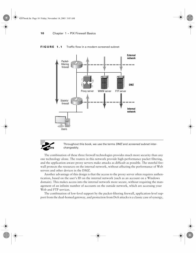
One type of screened subnet employs a packet-filtering router to separate the outside network from the DMZ. Then a stateful firewall connects the DMZ to the inside network. An application proxy typically resides inside the DMZ, so traffic does not flow directly from the inside network to the outside network or from the outside network directly to the inside network. Instead, all traf-fic from the inside network to the outside network flows to and from the proxy server. However, traffic from the outside network to the other servers, such as the Web and FTP servers, does not pass through the proxy server, but goes directly to the appropriate server. The data flow of this design is shown in Figure 1.1.
4287book.fm Page 9 Friday, November 14, 2003 3:05 AM
10
Chapter 1 �
PIX Firewall Basics
F I G U R E 1 . 1
Traffic flow in a modern screened subnet
Throughout this book, we use the terms
DMZ
and
screened subnet
inter-
changeably.
The combination of these three firewall technologies provides much more security than any one technology alone. The routers in this network provide high-performance packet filtering, and the application-aware proxy servers make attacks as difficult as possible. The stateful fire-wall protects the resources on the internal network, without affecting the performance of Web servers and other devices in the DMZ.
Another advantage of this design is that the access to the proxy server often requires authen-tication, based on the user’s ID on the internal network (such as an account on a Windows domain). This makes access into the internal network more secure, without requiring the man-agement of an infinite number of accounts on the outside network, which are accessing your Web and FTP services.
The combination of low-level support by the packet-filtering firewall, application-level sup-port from the dual-homed gateway, and protection from DoS attacks is a classic case of synergy,
DMZ
Externalnetwork
Internalnetwork
WWW server FTP server
Packet-filteringfirewall
Stateful firewall
Users
Proxy server
4287book.fm Page 10 Friday, November 14, 2003 3:05 AM
Reviewing Firewall Technologies
11
where the whole is greater than the sum of the parts. This technique is sometimes called
defense in depth.
A Stateful Firewall with Multiple Interfaces
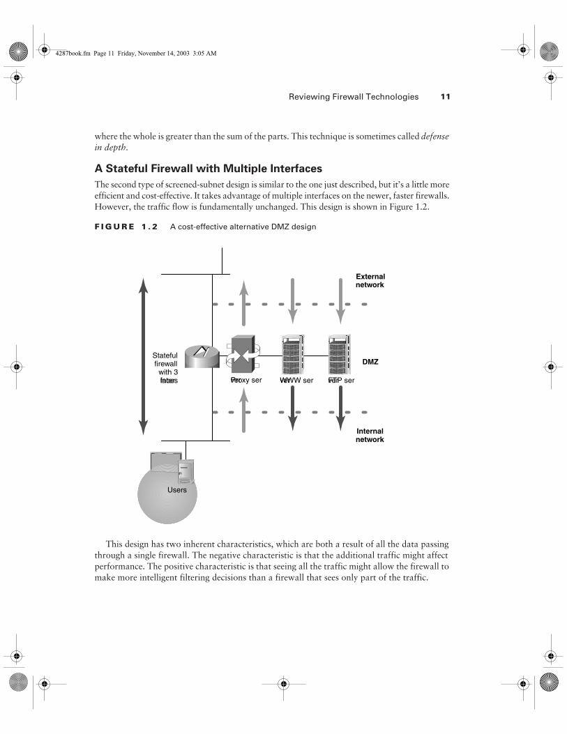
The second type of screened-subnet design is similar to the one just described, but it’s a little more efficient and cost-effective. It takes advantage of multiple interfaces on the newer, faster firewalls. However, the traffic flow is fundamentally unchanged. This design is shown in Figure 1.2.
F I G U R E 1 . 2
A cost-effective alternative DMZ design
This design has two inherent characteristics, which are both a result of all the data passing through a single firewall. The negative characteristic is that the additional traffic might affect performance. The positive characteristic is that seeing all the traffic might allow the firewall to make more intelligent filtering decisions than a firewall that sees only part of the traffic.
DMZ
Externalnetwork
Internalnetwork
WWW server FTP server
Statefulfirewallwith 3interfaces
Users
Proxy server
4287book.fm Page 11 Friday, November 14, 2003 3:05 AM
12 Chapter 1 � PIX Firewall Basics
Hardware and Software Components of the Cisco Secure PIX FirewallNow that you understand the basic firewall technologies and their usefulness, we can describe the basic characteristics of the PIX Firewall. The PIX Firewall, where PIX is an acronym for pri-vate Internet eXchange, is one of the world’s premier firewalls because its unique operation pro-vides strong security and very high performance. It is not based upon a mainstream operating system, such as Windows or UNIX, but on a hardened, secure, embedded operating system know as Finesse. In this section, we will begin to discuss its operation and various features that contribute to its speed and protection.
Admittedly, the information in this section is more marketing-related than tech-nical, and as such, isn’t likely to be on the exam. However, it is important to understand the background and context in which Cisco places the PIX Firewall. This understanding will also benefit you immensely after the exam, when it comes time to select and install a firewall in your network.
The PIX Firewall has its roots in Network Address Translation (NAT), with the ability to maintain information about the state of each connection that passes through it, and then filter (permit or deny) traffic based on that state. For this reason, it is classified as a stateful firewall.
PIX Firewall Features
The PIX Firewall series uses specially designed hardware and a very small, proprietary, multi-threaded kernel. On the lower-end models, the hardware is fixed-configuration, but the higher-end models support modular interface cards for many different types of media, up to gigabit speeds. The advantage here is that the extraneous equipment and issues associated with hard drives, CD-ROMs, GUIs, monitors, keyboards, mice, and so on are eliminated, without losing the core functionality of the firewall.
The PIX Firewall features support for Internet Protocol Security (IPSec), virtual private net-works (VPNs), cut-through proxy switching, inbound and outbound authentication, failover, and more. These features are covered in this section and in later chapters.
Another feature, which administrators will appreciate, is that compared with some firewalls, particularly the ones running on general-purpose operating systems, the PIX Firewall is easy to configure and hard to misconfigure. Unlike many firewalls, the PIX Firewall hardware and soft-ware are based on a pessimistic, or restrictive, security model. In other words, by default, every-thing is denied. To allow network traffic to pass through the PIX Firewall it must be explicitly configured to accept that traffic.
The latest versions of the PIX Firewall operating system have even more new features. One of the most eagerly anticipated features is multicast support. The PIX Firewall now supports multi-cast routing (with the mroute command) and Internet Group Management Protocol (IGMP).
4287book.fm Page 12 Friday, November 14, 2003 3:05 AM

Hardware and Software Components of the Cisco Secure PIX Firewall 13
PIX Firewall Components
In this section, we will explore the parts that make up the PIX Firewall. Before we get into the nuts and bolts, you should understand that simplicity is an important competitive advantage in the realm of security, because as components in a system become more complex, there are more opportunities to take advantage of the system. The PIX Firewall has succeeded in maintaining a very simple, almost minimalist, list of components.
On the PIX Firewall, some of these components can be seen by typing the show version command at the privileged exec prompt, as seen in Listing 1.1 (we’ve boldfaced the sections of interest here for clarity).
Using the show version command
PIX# show version
Cisco Secure PIX Firewall Version 6.0(1)
Compiled on Thu 17-May-01 20:05 by morlee
PIX up 58 secs
Hardware: PIX-515, 64 MB RAM, CPU Pentium 200 MHz
Flash i28F640J5 @ 0x300, 16MB
BIOS Flash AT29C257 @ 0xfffd8000, 32KB
0: ethernet0: address is 0050.54ff.076d, irq 10
1: ethernet1: address is 0050.54ff.076e, irq 7
2: ethernet2: address is 00d0.b79d.8856, irq 9
Licensed Features:
Failover: Enabled
VPN-DES: Enabled
VPN-3DES: Disabled
Maximum Interfaces: 6
Cut-through Proxy: Enabled
Guards: Enabled
Websense: Enabled
Throughput: Unlimited
ISAKMP peers: Unlimited
Serial Number: 403420127 (0x180bb3df)
Activation Key: 0x9aa99a8d 0xc56166de 0x4ecd338a
0x5b6d06eb
PIX#
4287book.fm Page 13 Friday, November 14, 2003 3:05 AM
14 Chapter 1 � PIX Firewall Basics
As you can see, the components shown by the show version command are the central pro-cessing unit (CPU), random access memory (RAM), flash file system, system image, BIOS, inter-faces, and licensed features. Let’s take a closer look at each of these components.
CPU
The PIX Firewall uses the Intel Pentium line of processors as the CPU. This is where the software image is executed and most of the rules are processed. Also, tasks such as encryption using IPSec are performed here (unless an optional VPN accelerator card is installed, which offloads this processing to a dedicated processor).
The show version command shows the type and speed of the processor. The show cpu usage command gives the average processor utilization for the past five seconds, one minute, and five minutes, as in this example:
PIX# show cpu usage
CPU utilization for 5 seconds = 0%; 1 minute: 0%;5 minutes: 0%
PIX#
RAM
RAM is the primary memory used by the PIX Firewall. Instructions being executed by the CPU exist here. Also, RAM is used for packet buffers and the various tables, such as state informa-tion, dynamic NAT entries, the translation (xlate) tables (described in the “NAT Mechanisms” section later in this chapter), and more.
The sample show version output in Listing 1.1 shows that this PIX Firewall has 64MB of RAM. You can also use the show memory command to see the available or unused memory:
PIX# show memory
67108864 bytes total, 51089408 bytes free
PIX#
Flash File System
The physical flash memory used in PIX Firewalls is similar to that used in Cisco’s router and switch platforms. However, the file system used by the PIX Firewall is considerably different.
The file system used in Cisco’s IOS allows any number of files to be stored, including multiple images, copies of the configuration file, and so on. Each of these can be manipulated by a file-name. However, the PIX Firewall flash file system version 1 divides the flash into four sectors. Each of these sectors contains one file. Version 2 of the flash file system adds one more sector, for a total of five, to support the GUI configuration software, PIX Device Manager (PDM).
The show flashfs command shows the length of each file, but not their filenames:
PIX# show flashfs
flash file system: version:2 magic:0x12345679
file 0: origin: 0 length:2449464
4287book.fm Page 14 Friday, November 14, 2003 3:05 AM
Hardware and Software Components of the Cisco Secure PIX Firewall 15
file 1: origin: 2490368 length:1463
file 2: origin: 0 length:0
file 3: origin: 0 length:0
file 4: origin: 8257536 length:280
PIX#
The files are used as follows:� File 0 is the PIX Firewall binary image. This is the BIN file. (See the next section for details
on the PIX Firewall system image.)� File 1 is the PIX Firewall configuration data, viewed with the show config command.� File 2 contains the firewall’s IPSec key and certificates.� File 3 contains the PDM software.� File 4 contains downgrade information for previous versions.
Access to these files is much more restricted than access to the Cisco IOS flash file system. To enhance security, the ability to copy files from flash to FTP, TFTP, another file on the flash, or other locations is no longer available. Also gone are flash partitions and the detailed information, such as checksums. Although the lack of these features might not seem like an enhancement, their exclu-sion helps prevent your private keys from being stolen. The maintenance of the flash system—such as compacting, formatting, and squeezing—is handled automatically on the PIX Firewall.
System Image
The system image is a binary executable file that resides in file 0 in the flash. Older models store the image on 3.5-inch floppy disks. The image contains all the code for the PIX Firewall oper-ating system and all the features—NAT, IPSec, filtering, and so on.
Unlike Cisco IOS images, where there are many images for each platform and each image contains only a certain set of features, there is only one image per software version for the PIX Firewall. This image contains all the features Cisco has developed for PIX Firewall, but certain features may be enabled and disabled by the licensing keys (see the “Licensed Features” section later in this chapter).
To install or upgrade an image, you must copy it across the network, typically with TFTP, or replace the flash memory with flash containing the new image. For PIX Firewall models that use floppy disks, simply swap the floppy with the one containing the new image and reboot.
The PIX Firewall operating system itself is non-Unix, real-time, and embedded.
BIOS
The BIOS of the PIX Firewall operates in the same way as the BIOS of other Intel processor–based computers. It is responsible for the initial boot sequence and loading the PIX Firewall software image located in file 0.
The BIOS is stored in a special chip, separate from flash. Although upgrades to the BIOS are seldom necessary (an example would be date fixes for the Y2K bug), upgrading it is possible.
4287book.fm Page 15 Friday, November 14, 2003 3:05 AM
16 Chapter 1 � PIX Firewall Basics
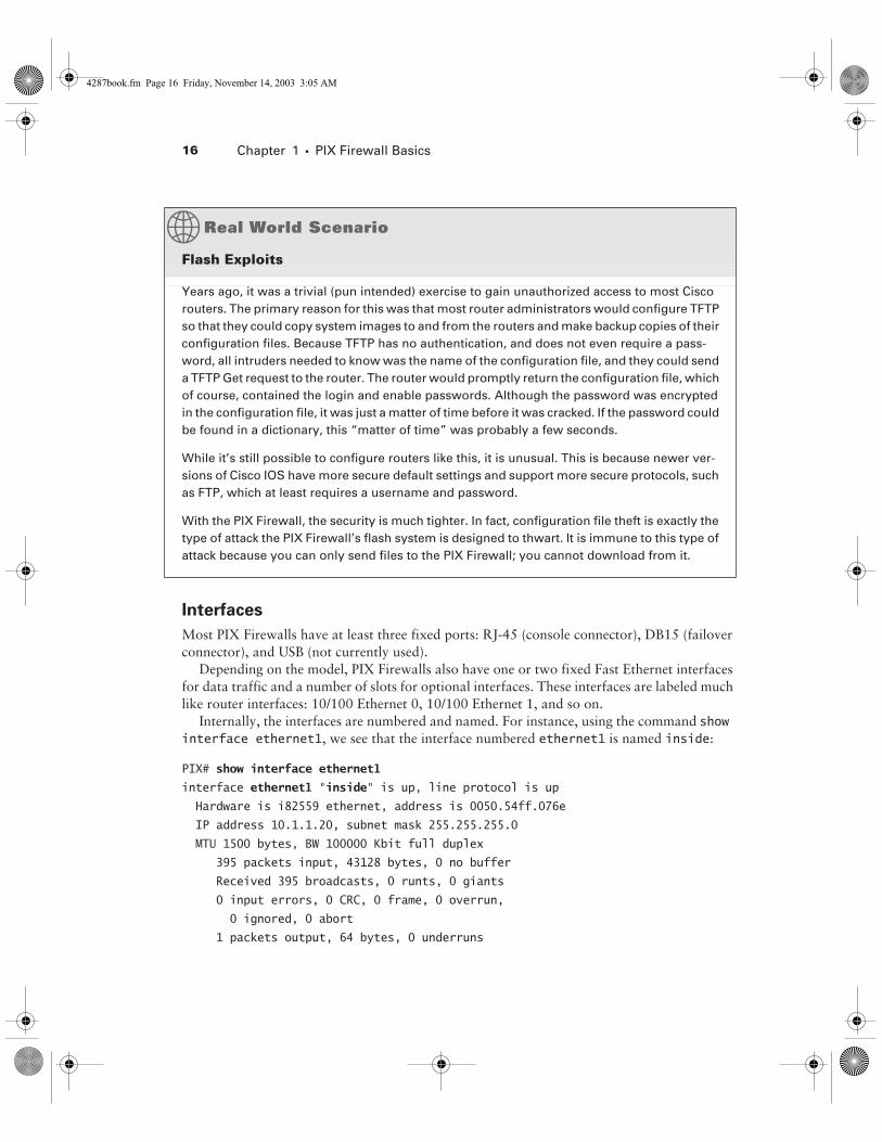
Interfaces
Most PIX Firewalls have at least three fixed ports: RJ-45 (console connector), DB15 (failover connector), and USB (not currently used).
Depending on the model, PIX Firewalls also have one or two fixed Fast Ethernet interfaces for data traffic and a number of slots for optional interfaces. These interfaces are labeled much like router interfaces: 10/100 Ethernet 0, 10/100 Ethernet 1, and so on.
Internally, the interfaces are numbered and named. For instance, using the command show interface ethernet1, we see that the interface numbered ethernet1 is named inside:
PIX# show interface ethernet1
interface ethernet1 "inside" is up, line protocol is up
Hardware is i82559 ethernet, address is 0050.54ff.076e
IP address 10.1.1.20, subnet mask 255.255.255.0
MTU 1500 bytes, BW 100000 Kbit full duplex
395 packets input, 43128 bytes, 0 no buffer
Received 395 broadcasts, 0 runts, 0 giants
0 input errors, 0 CRC, 0 frame, 0 overrun,
0 ignored, 0 abort
1 packets output, 64 bytes, 0 underruns
Flash Exploits
Years ago, it was a trivial (pun intended) exercise to gain unauthorized access to most Cisco routers. The primary reason for this was that most router administrators would configure TFTP so that they could copy system images to and from the routers and make backup copies of their configuration files. Because TFTP has no authentication, and does not even require a pass-word, all intruders needed to know was the name of the configuration file, and they could send a TFTP Get request to the router. The router would promptly return the configuration file, which of course, contained the login and enable passwords. Although the password was encrypted in the configuration file, it was just a matter of time before it was cracked. If the password could be found in a dictionary, this “matter of time” was probably a few seconds.
While it’s still possible to configure routers like this, it is unusual. This is because newer ver-sions of Cisco IOS have more secure default settings and support more secure protocols, such as FTP, which at least requires a username and password.
With the PIX Firewall, the security is much tighter. In fact, configuration file theft is exactly the type of attack the PIX Firewall’s flash system is designed to thwart. It is immune to this type of attack because you can only send files to the PIX Firewall; you cannot download from it.
4287book.fm Page 16 Friday, November 14, 2003 3:05 AM
Hardware and Software Components of the Cisco Secure PIX Firewall 17
0 output errors, 0 collisions, 0 interface resets
0 babbles, 0 late collisions, 0 deferred
1 lost carrier, 0 no carrier
input queue (curr/max blocks): hardware (128/128)
software (0/2)
output queue (curr/max blocks): hardware (0/2)
software (0/1)
PIX#
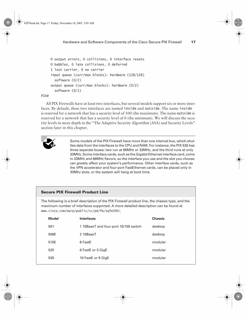
All PIX Firewalls have at least two interfaces, but several models support six or more inter-faces. By default, these two interfaces are named inside and outside. The name inside is reserved for a network that has a security level of 100 (the maximum). The name outside is reserved for a network that has a security level of 0 (the minimum). We will discuss the secu-rity levels in more depth in the “The Adaptive Security Algorithm (ASA) and Security Levels” section later in this chapter.
Some models of the PIX Firewall have more than one internal bus, which shut-tles data from the interfaces to the CPU and RAM. For instance, the PIX 535 has three separate buses: two run at 66MHz or 33MHz, and the third runs at only 33MHz. Some interface cards, such as the Gigabit Ethernet interface card, come in 33MHz and 66MHz flavors, so the interface you use and the slot you choose can greatly affect your system’s performance. Other interface cards, such as the VPN accelerator and four-port FastEthernet cards, can be placed only in 33Mhz slots, or the system will hang at boot time.
Secure PIX Firewall Product Line
The following is a brief description of the PIX Firewall product line, the chassis type, and the maximum number of interfaces supported. A more detailed description can be found at www.cisco.com/warp/public/cc/pd/fw/sqfw500/.
Model Interfaces Chassis
501 1 10BaseT and four-port 10/100 switch desktop
506E 2 10BaseT desktop
515E 6 FastE modular
525 8 FastE or 3 GigE modular
535 10 FastE or 9 GigE modular
4287book.fm Page 17 Friday, November 14, 2003 3:05 AM

18 Chapter 1 � PIX Firewall Basics
Licensed Features
Cisco has three basic licenses for the PIX Firewall:� The Restricted license sets a limit on the number of connections and interfaces and disables
failover.� The Unrestricted license has no limit on connections, enables failover, and allows as many
interfaces as the hardware supports.� The Failover license, the least expensive license, is intended for a backup firewall (when
using the failover feature) and assumes the license characteristics of the primary firewall.
In addition to these licenses, each PIX Firewall comes with a license for IPSec encryption using 56-bit Data Encryption Standard (DES) or Triple Data Encryption Standard (3DES) using 168 bits.
The encryption and firewall licenses are independent from the version of oper-ating system. The version of the operating system can be updated without affecting the licenses and the licenses can be updated without affecting the operating system version.
All features, including cut-through proxy, attack guards, N2H2, and Websense support are included in the Unrestricted license. Older models of the PIX Firewall had multiple Restricted versions that were limited to 128 connections or 1,024 concurrent connections.
Each PIX Firewall has a unique serial number. This serial number and the licenses purchased are used as the inputs to a mathematical formula that generates an activation key. This key is entered as the system image is being installed and determines which features are available on the firewall. When you do a flash upgrade, you need the serial number of the flash card, too.
As of version 6.2, the activation-key command was added so that code and boot-time upgrades are not needed to upgrade the activation key. For prior versions, to change your license, you must reload the system image. For instance, if you purchase a license-activation key for 3DES encryption and wish to install it on your PIX Firewall, you must copy the system image to the flash (again). During this process, you will be prompted for the activation code. The DES activation key provides 56-bit DES, and the 3DES activation key provides 168-bit 3DES.
PIX Firewall OperationNow that you understand the components of the PIX Firewall, let’s look at how they work together. As we mentioned earlier, the PIX Firewall has its roots in NAT. In fact, when the PIX Firewall was introduced in 1994, it was the first box capable of doing true RFC 1631 NAT.
Although it is possible to configure a PIX Firewall to not translate IP addresses, its switching process is based on NAT, and every packet must use this NAT mechanism. So, to understand how a PIX Firewall forwards packets, we must first define some NAT vocabulary. Then we will discuss the sequence in which packets are processed, and finally, the Adaptive Security Algorithm.
4287book.fm Page 18 Friday, November 14, 2003 3:05 AM

PIX Firewall Operation 19
Even if the PIX Firewall filtering is configured so that its ACLs will not deny any packets, packets that are not translated will not be forwarded. The PIX Firewall must have a translation slot to switch packets from one interface to another.
NAT Mechanisms
With NAT, a translation is a pair of IP addresses: local and global. The local address is on the network connected to the inside, or trusted, interface of the PIX Firewall. The global address is part of a network somewhere beyond the outside interface that is trusted less than the inside interface. The PIX Firewall translates the local address to the global address as the packet passes outbound through the firewall. It translates the global address to the local address as a packet passes inbound through the firewall.
Translations can be either static or dynamic. Static translations must be manually config-ured. Dynamic translations are created as packets that meet certain criteria arrive.
When the first packet in a series of packets arrives at the PIX Firewall from the inside inter-face, the PIX Firewall creates a translation slot. This “slot” is a software construct that keeps track of translations. Each translation uses one translation slot.
Connection slots are another software construct that the PIX Firewall uses to keep track of stateful information. A given pair of devices, such as a client and server, can multiplex several conversations between their two IP addresses. This is often accomplished via TCP and UDP ports. For instance, a client could connect to a server via telnet, FTP, and HTTP simultaneously, creating three separate TCP connections between the two devices. If this happened across a PIX Firewall, it would create a single translation slot and three connection slots. Each connection slot is bound to a translation slot.
The Restricted licenses used in older PIX Firewall models limit the number of connection slots to either 128 or 1,024. As of the time of this writing, “older” means the PIX Classic and those whose model numbers end in zero, such as PIX 520. The current models end in five, such as PIX 515, PIX 525, and PIX 535.
The translation table, which is usually abbreviated as xlate table, is the actual table in mem-ory that holds all the translation slots and connection slots. It is important to distinguish this table from the configuration file of the PIX Firewall. Just because you have configured a static entry does not mean it will appear in the output of the show xlate command. The PIX Firewall places an entry in this table only when a packet arrives. After a certain amount of inactivity (that is, after the PIX Firewall does not see any more packets that are part of this conversation), the PIX Firewall will remove the entry from the xlate table. Remember that the xlate table shows the current translations and connections.
4287book.fm Page 19 Friday, November 14, 2003 3:05 AM
20 Chapter 1 � PIX Firewall Basics
Packet Processing
Now that you know how NAT works, let’s look at how the PIX Firewall processes packets. We’ll see how it handles outbound packets, inbound packets, and routing.
Outbound Packets
When a packet arrives on the inside interface, the PIX Firewall first checks the xlate table for a translation slot. Specifically, this means the PIX Firewall is checking the source address of the IP header and searching the xlate table for a match. Its next actions depend on whether or not it finds a match.
Packets with Existing Translation Slots
If the PIX Firewall finds a match for the outbound packet’s source address, it knows it has seen packets from this address before and already created a dynamic translation slot, or it has a man-ually configured static translation slot. The PIX Firewall then processes the outbound packet as follows:� It takes the global address from the translation slot that corresponds to the local address it
just looked up in the xlate table and overwrites the source address in the IP header of the packet with the value of the global address.
� The other attributes, such as the checksums, are recalculated. (Otherwise, the packet would be discarded upon arrival, since the change in the IP header would change the value of the checksum.)
� The packet is then forwarded out the outside interface.
Packets without Existing Translation Slots
If the PIX Firewall receives a packet on the inside interface that does not have a current trans-lation slot in the xlate table, it can dynamically create an entry if configured to do so. In this case, when the packet arrives, the PIX Firewall checks the source address and finds no match in the xlate table. It then follows these steps to process the outbound packet:� The PIX Firewall makes sure it has sufficient connections, which are determined by the
license.� It creates the translation slot by reserving an unused IP address from the global NAT pool
and entering this global address along with the source address from the IP header into the translation slot.
� With the translation slot created, the source address is overwritten with the global address.� The checksum and other values are recalculated.� The packet is transmitted on the outside interface.
Inbound Packets
For packets that arrive on the outside interface, destined for the inside network, the PIX Fire-wall behaves quite differently than it does for packets that arrive on the inside interface. This
4287book.fm Page 20 Friday, November 14, 2003 3:05 AM
PIX Firewall Operation 21
is because the outside network is, by definition, less trusted. By default, packets from the outside do not create translation slots, so they cannot be switched to the inside interface without a static NAT mapping. This makes the PIX Firewall very secure, from an architectural standpoint.
But even before the PIX Firewall checks for an existing entry in the xlate table, packets from an outside interface must match criteria specified in an ACL. Only after an incoming packet matches the ACL will it be processed further. The combination of the ACL and translation slot is the primary source of the PIX Firewall’s security.
Do not confuse the definition of stateful firewalls with this section’s description of the operation of the PIX Firewall. There are many brands of stateful firewalls, but the PIX Firewall’s operation is unique.
Routing
As you can see from the description of packet processing in the previous sections, the PIX Fire-wall is not a router. This is an important distinction, because many other brands of firewalls are, in fact, routers, with packet-filtering or even stateful capabilities added on. For instance, the Cisco IOS Firewall is a full-featured, stateful firewall that runs on a Cisco router, but it pro-cesses packets just as it would if it were running a basic Cisco IOS image, except that it adds the stateful filtering feature. Although the mode of operation detailed in the previous sections makes the PIX Firewall much more secure, it also has some limitations related to its routing pro-tocol support. The configuring of routing will be discussed in the next chapter.
The Adaptive Security Algorithm (ASA) and
Security Levels
Cisco’s ASA is the basis for the PIX Firewall’s security, and it includes much of the information discussed in the previous sections. However, it can be summarized into a few rules that govern how packets are inspected and permitted or denied:� All packets must have a connection slot to be transmitted.� All packets are allowed to travel from a more secure interface to a less secure interface
unless specifically denied (for example, by an ACL).� All packets from a less secure interface to a more secure interface are denied, unless specif-
ically allowed.� All ICMP packets are denied unless you specifically configure the PIX Firewall to accept them.� When the PIX Firewall denies a packet, it is “dropped” (received but not transmitted), and
the action is noted in the logs.� Monitor return packets to ensure they are valid.
Security on the PIX Firewall is relative, and it’s critical that you understand this. Specifically, what is allowed and disallowed by default depends on which interfaces a packet enters and leaves.
4287book.fm Page 21 Friday, November 14, 2003 3:05 AM
22 Chapter 1 � PIX Firewall Basics
Each interface is assigned a value, called the security level, from 0 to 100, where 100 is com-pletely trusted and 0 is completely untrusted. This allows a PIX Firewall with several interfaces to be configured securely.
For instance, you might have five interfaces on your PIX Firewall and assign them security levels as follows:
In this scenario, traffic from your internal network would, by default, be able to access any of the other four networks. Your remote users would be able to get to your business partner, the DMZ, and the Internet; however, you must explicitly configure the PIX Firewall to let them inside your internal network because it has a higher security level. Your business partners would be able to access your shared systems on the DMZ and the Internet by default, although you could restrict this with an ACL. Your partners would not be able to get to your internal network or the modems on your remote-access network, unless you explicitly grant them permission in the configuration. The systems on the DMZ would be able to access only the Internet. Finally, the Internet would not be able to access any of the other four networks, again, without explicit con-figuration.
In summary, the PIX Firewall controls access via the translation and connection slots we mentioned earlier. The PIX Firewall simply does not allow a packet from a less-trusted inter-face, destined for a more-trusted interface, to create a translation or connection slot, without explicitly configuring the NAT translation and an ACL.
Working with the Firewall Services Module (FWSM)If you want more firewall horsepower you should consider using the Firewall Services Module for the Catalyst 6500 Series switch and the 7600 Series Internet router with either a Supervisor 1A with MSFC2 (Catalyst operating system only) or Supervisor 2 with MSFC2. The FWSM is based on Cisco PIX Firewall technology and uses the same time-tested Cisco PIX Firewall Oper-ating System, a secure, real-time operating system.
This is a multigigabit firewall module with 1GB RAM and 128MB flash memory that pro-vides up to 5Gbps of throughput. This module is switch fabric–aware and runs the entire
Connection Security Level Default Access
Internal network 100 All
Remote-access network 75 Business partner, DMZ, and Internet
Business partner 50 DMZ and Internet
DMZ 25 Internet
Internet 0 None
4287book.fm Page 22 Friday, November 14, 2003 3:05 AM
Working with the Firewall Services Module (FWSM) 23
PIX 6.0 software feature set and some PIX 6.2 features including command authorization, object grouping, and URL-filtering enhancements. This module supports up to 100 virtual LANs (VLANs) with no physical interfaces.
There are some caveats to using the FWSM over a stand-alone PIX Firewall. There is no sup-port for IDS signatures, the PIX Firewall Manager, the Cisco Secure Policy Manager, conduit commands, the Dynamic Host Configuration Protocol (DHCP) client, and VPN except for IPSec for management purposes. If you need more than 5Gbps of throughput, then you can install up to four modules per chassis for a total of 20Gbps. There is, however, support for the Open Shortest Path First (OSPF) routing protocol, something that will not be available until ver-sion 6.3 of the PIX Firewall operating system. We will not discuss the OSPF support in this book because it is beyond the scope of the current test.
In this section, we will have a configuration overview followed by how to configure the switch for the FWSM using both IOS and CatOS-based switches. Next we will show you how to connect to the module and what tasks need to be completed for the FWSM to start protecting the secured VLANs.
Overview of Configuration
The FWSM can provide access control to the whole inside network, or it can segregate multiple security zones through VLAN interfaces of different security levels. These VLAN interfaces are known as secure VLANs because they are handled by the FWSM and not by the supervisor engine. There is one secure VLAN known as the secure VLAN interface (SVI), and it provides a layer 3 secure VLAN interface between the module and the router on the supervisor engine so they can communicate with each other.
One SVI must be configured between each FWSM in the chassis and the supervisor engine module router. Only one SVI can exist between a given FWSM and the router on the supervisor engine. There can be multiple SVIs in a device but only one can exist between each FWSM and the supervisor engine.
You can configure secure VLANs using both the Cisco IOS and CatOS operating systems. The secure VLAN information is passed from the switch operating system software to the fire-wall module when it comes on line. The module accepts traffic on the secure VLANs only after the firewall interfaces are configured on the module corresponding to the secure VLANs defined on the switch. The firewall software will not see traffic on VLANs that are unknown to the fire-wall module or on the secure VLANs without having corresponding firewall interfaces defined.
When the firewall module comes on line, the Network Management Processor (NMP) sends a message that specifies the secure VLANs that are defined for that particular firewall module. If a VLAN is active and is configured as a secure VLAN, the information about the new active VLAN is sent to the corresponding FWSM.
The FWSM configuration has the following characteristics:� Each firewall interface is a layer 3 interface and has an IP address.� Each firewall interface has a fixed VLAN, which is defined on the switch.� The switch MSFC is used as a router for only the SVI so the devices can communicate.
4287book.fm Page 23 Friday, November 14, 2003 3:05 AM

24 Chapter 1 � PIX Firewall Basics
� The module views all networks attached to an interface as having the same security level.� Traffic from non-firewall VLANs is routed through the MSFC without being processed by
the FWSM.
Configuring an IOS Switch
To set up the configuration for the FWSM on the switch using the Cisco IOS CLI, follow these steps:
1. Create the VLANs to be used by the module using the vlan number command.
2. Define an SVI on the MSFC using the interface vlan number command or you will be unable to configure VLANs on the module.
3. Create a firewall group of secure VLANs using the firewall vlan-group firewall-group vlan-range command.
4. Attach the VLAN and firewall group to the slot where the FWSM is located using the firewall module module number vlan-group firewall-group command.
You can also view the defined VLAN groups and the module(s) using the show firewall vlan-group and show firewall module commands. The following in an example of using the above commands to create secure VLANs and the SVI, and tying the VLANs to the slot for the FWSM:
MSFC# conf t
Enter configuration commands, one per line. End with CNTL/Z.
MSFC(config)# vlan 15
MSFC(config-vlan)# vlan 16
MSFC(config-vlan)# vlan 17
MSFC(config-vlan)# exit
MSFC(config)# firewall vlan-group 10 15-17
MSFC(config)# firewall vlan-group 21 30-45
MSFC(config)# firewall module 8 vlan-group 10,21
MSFC(config)# int vlan 55
MSFC(config-if)# ip address 192.168.1.1 255.255.255.0
MSFC(config-if)# no shut
MSFC(config-if)# end
MSFC# show firewall vlan-group
Group vlans
----- ------
10 15-17
21 30-45
MSFC# show firewall module
Module Vlan-groups
8 10,21,
MSFC#
4287book.fm Page 24 Friday, November 14, 2003 3:05 AM
Working with the Firewall Services Module (FWSM) 25
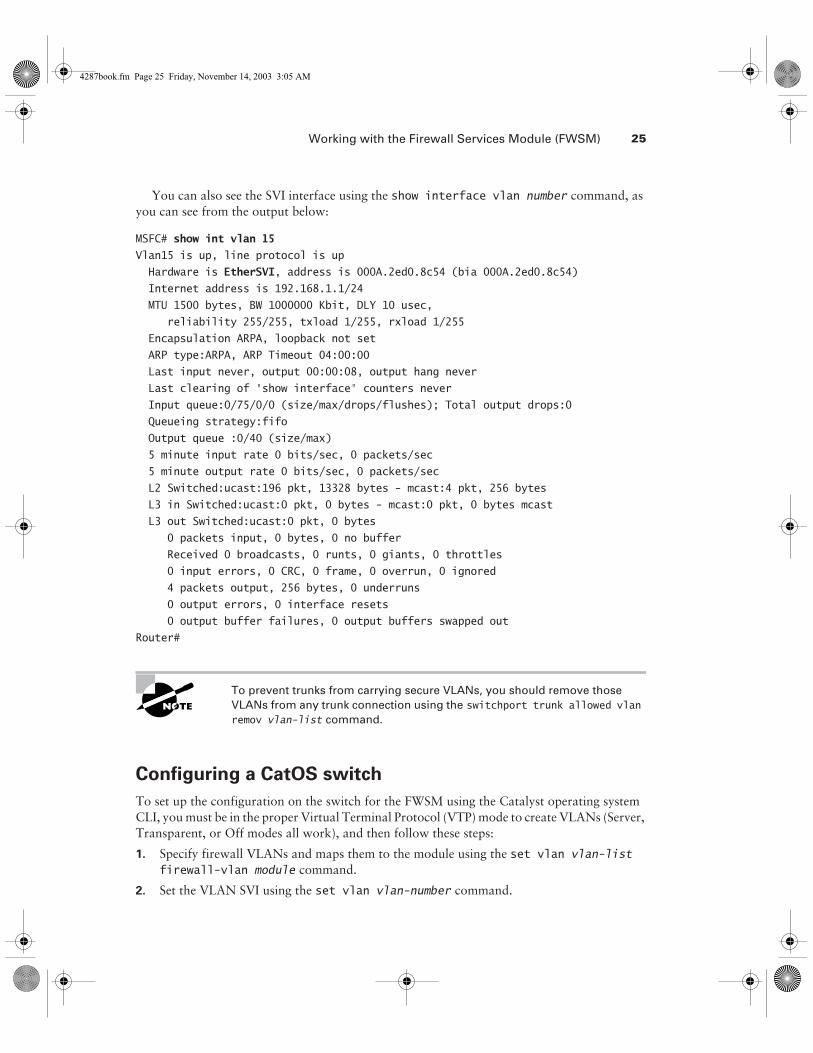
You can also see the SVI interface using the show interface vlan number command, as you can see from the output below:
MSFC# show int vlan 15
Vlan15 is up, line protocol is up
Hardware is EtherSVI, address is 000A.2ed0.8c54 (bia 000A.2ed0.8c54)
Internet address is 192.168.1.1/24
MTU 1500 bytes, BW 1000000 Kbit, DLY 10 usec,
reliability 255/255, txload 1/255, rxload 1/255
Encapsulation ARPA, loopback not set
ARP type:ARPA, ARP Timeout 04:00:00
Last input never, output 00:00:08, output hang never
Last clearing of "show interface" counters never
Input queue:0/75/0/0 (size/max/drops/flushes); Total output drops:0
Queueing strategy:fifo
Output queue :0/40 (size/max)
5 minute input rate 0 bits/sec, 0 packets/sec
5 minute output rate 0 bits/sec, 0 packets/sec
L2 Switched:ucast:196 pkt, 13328 bytes - mcast:4 pkt, 256 bytes
L3 in Switched:ucast:0 pkt, 0 bytes - mcast:0 pkt, 0 bytes mcast
L3 out Switched:ucast:0 pkt, 0 bytes
0 packets input, 0 bytes, 0 no buffer
Received 0 broadcasts, 0 runts, 0 giants, 0 throttles
0 input errors, 0 CRC, 0 frame, 0 overrun, 0 ignored
4 packets output, 256 bytes, 0 underruns
0 output errors, 0 interface resets
0 output buffer failures, 0 output buffers swapped outRouter#
To prevent trunks from carrying secure VLANs, you should remove those VLANs from any trunk connection using the switchport trunk allowed vlan remov vlan-list command.
Configuring a CatOS switch
To set up the configuration on the switch for the FWSM using the Catalyst operating system CLI, you must be in the proper Virtual Terminal Protocol (VTP) mode to create VLANs (Server, Transparent, or Off modes all work), and then follow these steps:
1. Specify firewall VLANs and maps them to the module using the set vlan vlan-list firewall-vlan module command.
2. Set the VLAN SVI using the set vlan vlan-number command.
4287book.fm Page 25 Friday, November 14, 2003 3:05 AM
26 Chapter 1 � PIX Firewall Basics
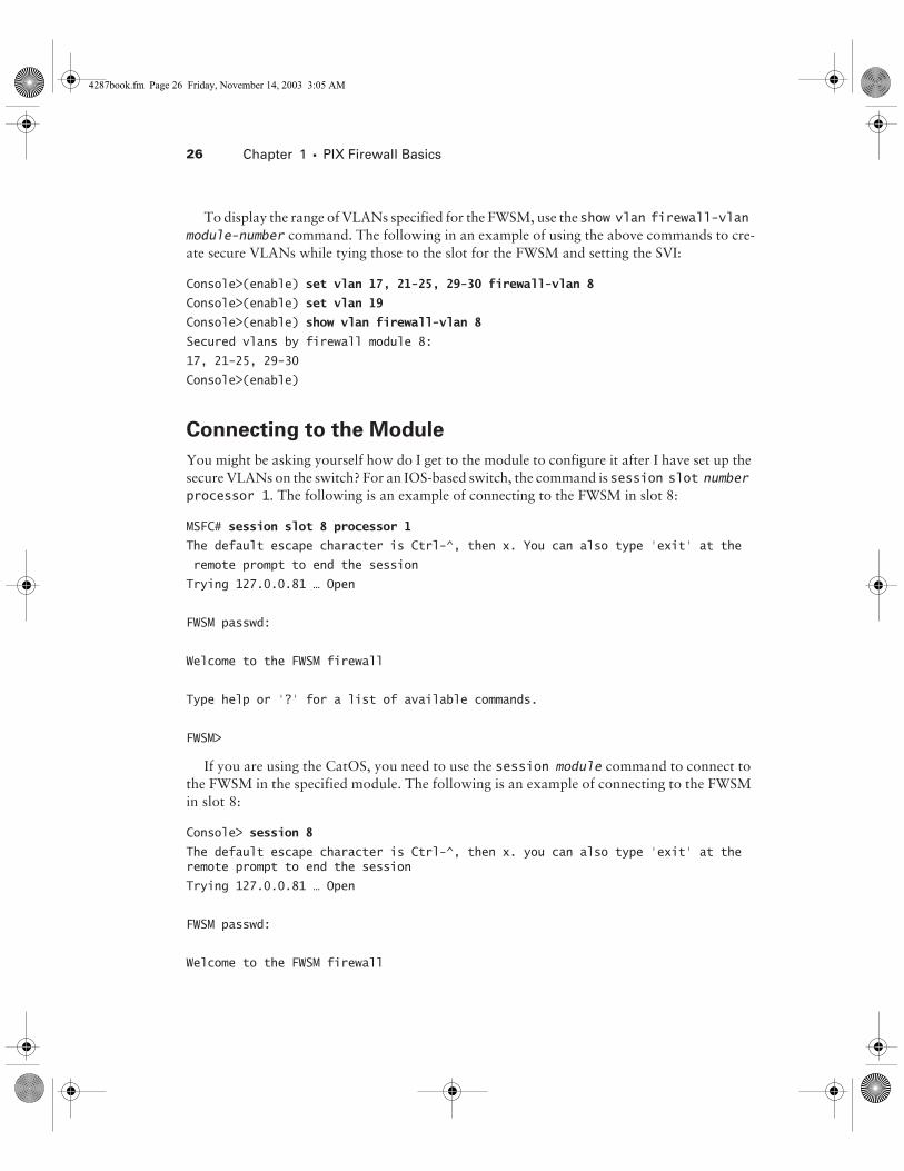
To display the range of VLANs specified for the FWSM, use the show vlan firewall-vlan module-number command. The following in an example of using the above commands to cre-ate secure VLANs while tying those to the slot for the FWSM and setting the SVI:
Console>(enable) set vlan 17, 21-25, 29-30 firewall-vlan 8
Console>(enable) set vlan 19
Console>(enable) show vlan firewall-vlan 8
Secured vlans by firewall module 8:
17, 21-25, 29-30
Console>(enable)
Connecting to the Module
You might be asking yourself how do I get to the module to configure it after I have set up the secure VLANs on the switch? For an IOS-based switch, the command is session slot number processor 1. The following is an example of connecting to the FWSM in slot 8:
MSFC# session slot 8 processor 1
The default escape character is Ctrl-^, then x. You can also type ‘exit’ at the
remote prompt to end the session
Trying 127.0.0.81 … Open
FWSM passwd:
Welcome to the FWSM firewall
Type help or '?' for a list of available commands.
FWSM>
If you are using the CatOS, you need to use the session module command to connect to the FWSM in the specified module. The following is an example of connecting to the FWSM in slot 8:
Console> session 8
The default escape character is Ctrl-^, then x. you can also type ‘exit’ at the remote prompt to end the session
Trying 127.0.0.81 … Open
FWSM passwd:
Welcome to the FWSM firewall
4287book.fm Page 26 Friday, November 14, 2003 3:05 AM
Working with the Firewall Services Module (FWSM) 27
Type help or '?' for a list of available commands.
FWSM>
If the module does not boot into the application partition, you might need to reset the mod-ule with the hw-module module slot-number reset cf:4 command for Cisco IOS and reset module-number for the CatOS-based switch.
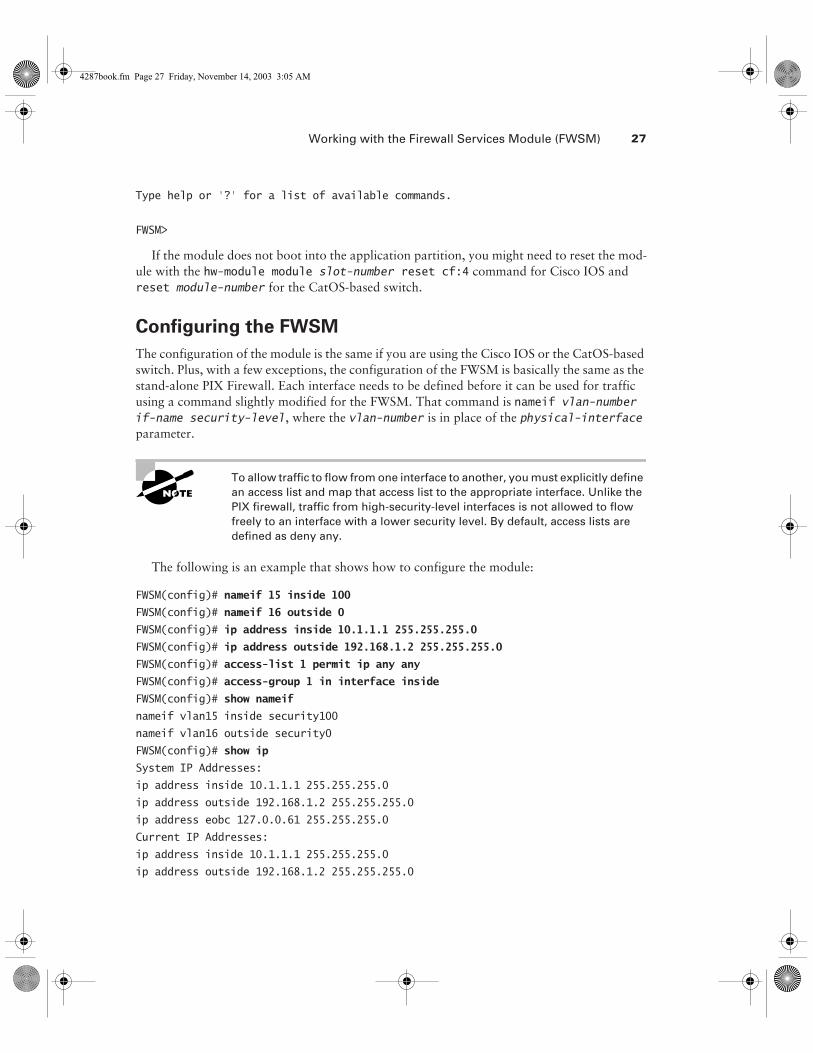
Configuring the FWSM
The configuration of the module is the same if you are using the Cisco IOS or the CatOS-based switch. Plus, with a few exceptions, the configuration of the FWSM is basically the same as the stand-alone PIX Firewall. Each interface needs to be defined before it can be used for traffic using a command slightly modified for the FWSM. That command is nameif vlan-number if-name security-level, where the vlan-number is in place of the physical-interface parameter.
To allow traffic to flow from one interface to another, you must explicitly define an access list and map that access list to the appropriate interface. Unlike the PIX firewall, traffic from high-security-level interfaces is not allowed to flow freely to an interface with a lower security level. By default, access lists are defined as deny any.
The following is an example that shows how to configure the module:
FWSM(config)# nameif 15 inside 100
FWSM(config)# nameif 16 outside 0
FWSM(config)# ip address inside 10.1.1.1 255.255.255.0
FWSM(config)# ip address outside 192.168.1.2 255.255.255.0
FWSM(config)# access-list 1 permit ip any any
FWSM(config)# access-group 1 in interface inside
FWSM(config)# show nameif
nameif vlan15 inside security100
nameif vlan16 outside security0
FWSM(config)# show ip
System IP Addresses:
ip address inside 10.1.1.1 255.255.255.0
ip address outside 192.168.1.2 255.255.255.0
ip address eobc 127.0.0.61 255.255.255.0
Current IP Addresses:
ip address inside 10.1.1.1 255.255.255.0
ip address outside 192.168.1.2 255.255.255.0
4287book.fm Page 27 Friday, November 14, 2003 3:05 AM
28 Chapter 1 � PIX Firewall Basics
ip address eobc 127.0.0.61 255.255.255.0
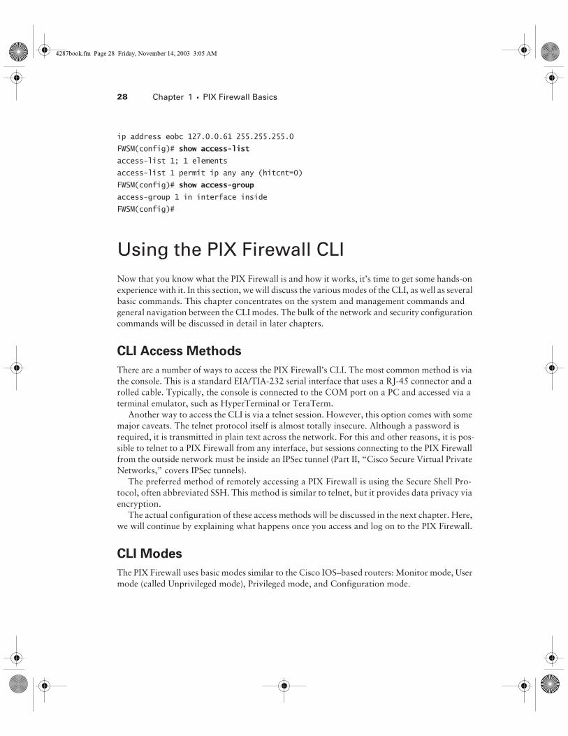
FWSM(config)# show access-list
access-list 1; 1 elements
access-list 1 permit ip any any (hitcnt=0)
FWSM(config)# show access-group
access-group 1 in interface inside
FWSM(config)#
Using the PIX Firewall CLINow that you know what the PIX Firewall is and how it works, it’s time to get some hands-on experience with it. In this section, we will discuss the various modes of the CLI, as well as several basic commands. This chapter concentrates on the system and management commands and general navigation between the CLI modes. The bulk of the network and security configuration commands will be discussed in detail in later chapters.
CLI Access Methods
There are a number of ways to access the PIX Firewall’s CLI. The most common method is via the console. This is a standard EIA/TIA-232 serial interface that uses a RJ-45 connector and a rolled cable. Typically, the console is connected to the COM port on a PC and accessed via a terminal emulator, such as HyperTerminal or TeraTerm.
Another way to access the CLI is via a telnet session. However, this option comes with some major caveats. The telnet protocol itself is almost totally insecure. Although a password is required, it is transmitted in plain text across the network. For this and other reasons, it is pos-sible to telnet to a PIX Firewall from any interface, but sessions connecting to the PIX Firewall from the outside network must be inside an IPSec tunnel (Part II, “Cisco Secure Virtual Private Networks,” covers IPSec tunnels).
The preferred method of remotely accessing a PIX Firewall is using the Secure Shell Pro-tocol, often abbreviated SSH. This method is similar to telnet, but it provides data privacy via encryption.
The actual configuration of these access methods will be discussed in the next chapter. Here, we will continue by explaining what happens once you access and log on to the PIX Firewall.
CLI Modes
The PIX Firewall uses basic modes similar to the Cisco IOS–based routers: Monitor mode, User mode (called Unprivileged mode), Privileged mode, and Configuration mode.
4287book.fm Page 28 Friday, November 14, 2003 3:05 AM
Using the PIX Firewall CLI 29
Monitor Mode
Monitor mode is used when you need to upgrade the software on a PIX Firewall that does not have an internal floppy drive. All of the new PIX Firewalls do not have internal floppy drives. You get into Monitor mode during the bootup sequence, when you’re prompted to use either BREAK or Esc to interrupt the Flash boot. You have 10 seconds to interrupt the normal boot process. You then press the Esc key or send a BREAK character, which will put you in Monitor mode. The monitor> prompt is then displayed. This mode is sometimes overlooked in the Cisco documentation.
Unprivileged Mode
After the initial logon, you’re in Unprivileged mode. This is a highly restricted mode that, by default, has only a few commands including enable, pager, and quit. The prompt in Unpriv-ileged mode is marked by the greater-than symbol (>) after the system name.
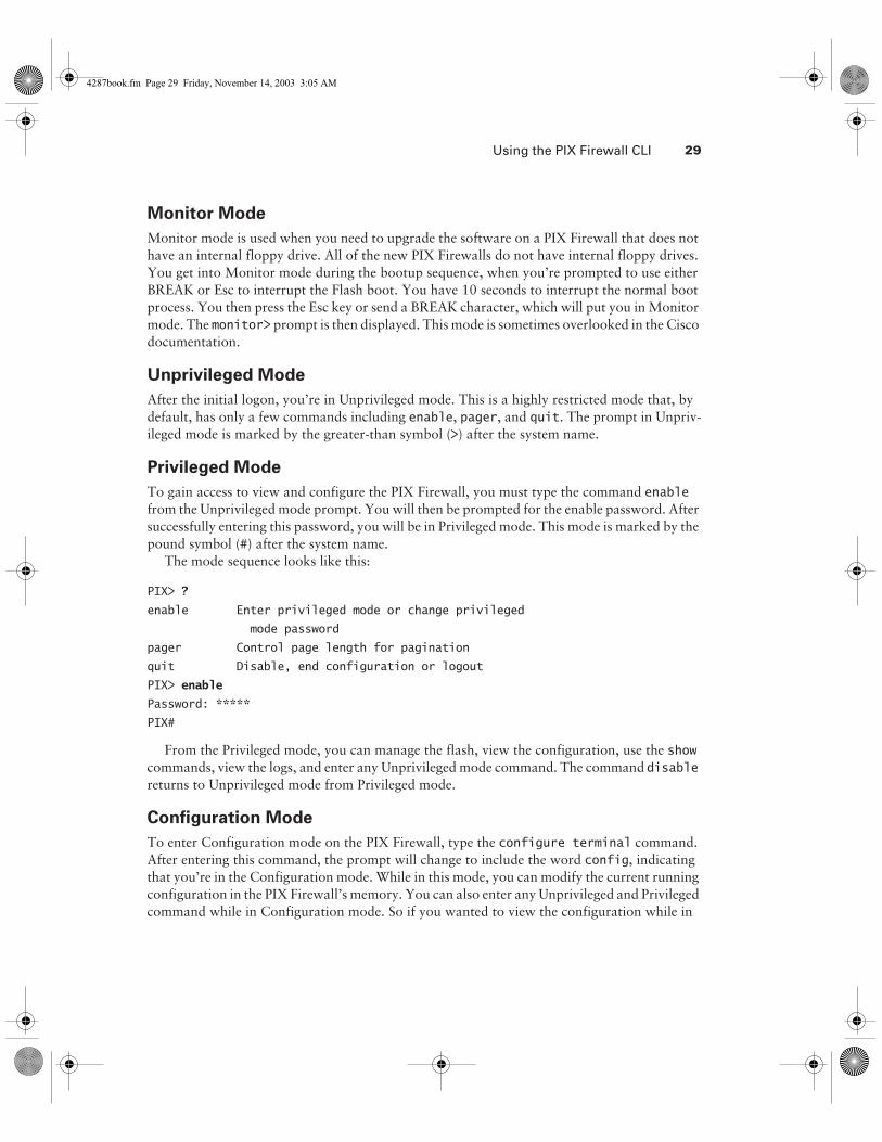
Privileged Mode
To gain access to view and configure the PIX Firewall, you must type the command enable from the Unprivileged mode prompt. You will then be prompted for the enable password. After successfully entering this password, you will be in Privileged mode. This mode is marked by the pound symbol (#) after the system name.
The mode sequence looks like this:
PIX> ?
enable Enter privileged mode or change privileged
mode password
pager Control page length for pagination
quit Disable, end configuration or logout
PIX> enable
Password: *****
PIX#
From the Privileged mode, you can manage the flash, view the configuration, use the show commands, view the logs, and enter any Unprivileged mode command. The command disable returns to Unprivileged mode from Privileged mode.
Configuration Mode
To enter Configuration mode on the PIX Firewall, type the configure terminal command. After entering this command, the prompt will change to include the word config, indicating that you’re in the Configuration mode. While in this mode, you can modify the current running configuration in the PIX Firewall’s memory. You can also enter any Unprivileged and Privileged command while in Configuration mode. So if you wanted to view the configuration while in
4287book.fm Page 29 Friday, November 14, 2003 3:05 AM
30 Chapter 1 � PIX Firewall Basics
Configuration mode just enter the write terminal command to view the current configura-tion in RAM. This is a different behavior from Cisco IOS where you must exit the configuration mode to enter Unprivileged or Privileged commands. Any command you type will take effect immediately but still needs to be saved to flash memory, making the changes permanent. You can return to Privileged mode by typing the command exit.
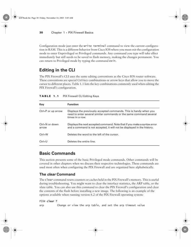
Editing in the CLI
The PIX Firewall’s CLI uses the same editing conventions as the Cisco IOS router software. These conventions are special Ctrl-key combinations or arrow keys that allow you to move the cursor to different places. Table 1.1 lists the key combinations commonly used when editing the PIX Firewall’s configuration.
Basic Commands
This section presents some of the basic Privileged mode commands. Other commands will be covered in other chapters when we discuss their respective technologies. These commands are used most often when configuring the PIX Firewall and are organized here alphabetically.
The clear Command
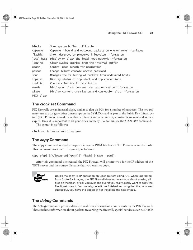
The clear command resets counters or caches held in the PIX Firewall’s memory. This is useful during troubleshooting. You might want to clear the interface statistics, the ARP table, or the xlate table. You can also use this command to clear the PIX Firewall’s configuration and clear the contents of the flash before installing a new image. The following is an example of the options available when running version 6.2 of the PIX Firewall operating system:
PIX# clear ?
arp Change or view the arp table, and set the arp timeout value
T A B L E 1 . 1 PIX Firewall CLI Editing Keys
Key Function
Ctrl+P or up arrow Displays the previously accepted commands. This is handy when you need to enter several similar commands or the same command several times in a row.
Ctrl+N or down arrow
Displays the next accepted command. Note that if you make a syntax error and a command is not accepted, it will not be displayed in the history.
Ctrl+W Deletes the word to the left of the cursor.
Ctrl+U Deletes the entire line.
4287book.fm Page 30 Friday, November 14, 2003 3:05 AM
Using the PIX Firewall CLI 31
blocks Show system buffer utilization
capture Capture inbound and outbound packets on one or more interfaces
flashfs Show, destroy, or preserve filesystem information
local-host Display or clear the local host network information
logging Clear syslog entries from the internal buffer
pager Control page length for pagination
passwd Change Telnet console access password
shun Manages the filtering of packets from undesired hosts
tcpstat Display status of tcp stack and tcp connections
traffic Counters for traffic statistics
uauth Display or clear current user authorization information
xlate Display current translation and connection slot information
PIX# clear
The clock set Command
PIX Firewalls use an internal clock, similar to that on PCs, for a number of purposes. The two pri-mary uses are for generating timestamps on the SYSLOGs and as part of the Public Key Infrastruc-ture (PKI) Protocol, to make sure that certificates and other security constructs are removed as they expire. Thus, it is important to set your clock correctly. To do this, use the clock set command.
The syntax is as follows:
clock set hh:mm:ss month day year
The copy Command
The copy command is used to copy an image or PDM file from a TFTP server onto the flash. This command uses the URL syntax, as follows:
copy tftp[:[[//location][/path]]] flash[:[image | pdm]]
After this command is executed, the PIX Firewall will prompt you for the IP address of the TFTP server and the source filename that you want to copy.
Unlike the copy TFTP operation on Cisco routers using IOS, when upgrading from 5.x to 6.x images, the PIX Firewall does not warn you about erasing all files on the flash, or ask you over and over if you really, really want to copy the file. It just does it. Fortunately, once it has finished verifying that the copy was successful, you have the option of not installing the new image.
The debug Commands
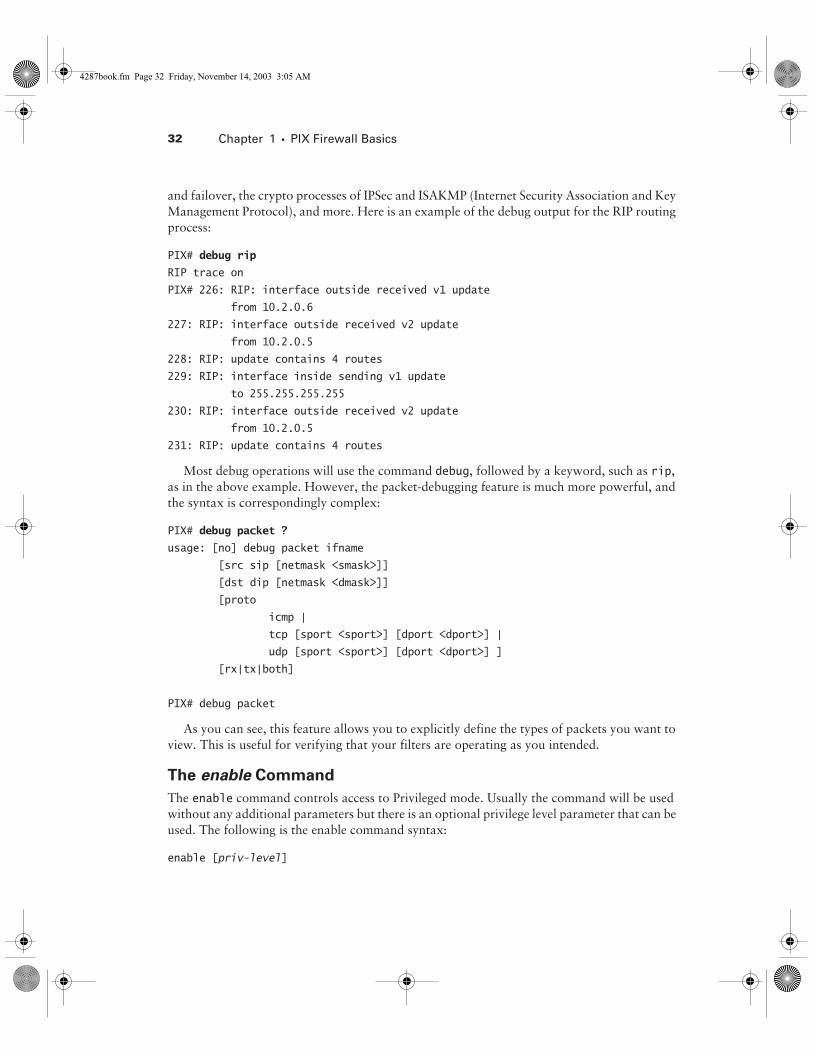
The debug commands provide detailed, real-time information about events on the PIX Firewall. These include information about packets traversing the firewall, special services such as DHCP
4287book.fm Page 31 Friday, November 14, 2003 3:05 AM
32 Chapter 1 � PIX Firewall Basics
and failover, the crypto processes of IPSec and ISAKMP (Internet Security Association and Key Management Protocol), and more. Here is an example of the debug output for the RIP routing process:
PIX# debug rip
RIP trace on
PIX# 226: RIP: interface outside received v1 update
from 10.2.0.6
227: RIP: interface outside received v2 update
from 10.2.0.5
228: RIP: update contains 4 routes
229: RIP: interface inside sending v1 update
to 255.255.255.255
230: RIP: interface outside received v2 update
from 10.2.0.5
231: RIP: update contains 4 routes
Most debug operations will use the command debug, followed by a keyword, such as rip, as in the above example. However, the packet-debugging feature is much more powerful, and the syntax is correspondingly complex:
PIX# debug packet ?
usage: [no] debug packet ifname
[src sip [netmask <smask>]]
[dst dip [netmask <dmask>]]
[proto
icmp |
tcp [sport <sport>] [dport <dport>] |
udp [sport <sport>] [dport <dport>] ]
[rx|tx|both]
PIX# debug packet
As you can see, this feature allows you to explicitly define the types of packets you want to view. This is useful for verifying that your filters are operating as you intended.
The enable Command
The enable command controls access to Privileged mode. Usually the command will be used without any additional parameters but there is an optional privilege level parameter that can be used. The following is the enable command syntax:
enable [priv-level]
4287book.fm Page 32 Friday, November 14, 2003 3:05 AM
Using the PIX Firewall CLI 33
By default the enable command asks for the level 15 enable password but you can specify the privilege level from 0 to 15. We will talk about how these privilege levels are used when we talk about the privilege command in Chapter 3, “ACLs, Filtering, Object Grouping, and AAA.” Now let’s talk about how to configure the enable password for each level.
The enable password Command
The enable password command is used to set the password that allows access to the Privileged mode. The password is alphanumeric and can be at least three characters and up to 16 charac-ters long. Optionally there is a level parameter followed by the privilege level, which creates a password for that particular privilege level. The syntax is as follows:
enable password password [level priv-level] [encrypted]
If you are entering a password that is already encrypted, you must use the encrypted key-word after your password. Also, an encrypted string will always be exactly 16 characters long (so you cannot tell how long the unencrypted password is).
The passwd Command
The passwd command sets the password for telnet and SSH access to the PIX Firewall. Telnet and SSH will be discussed in the next chapter. The syntax is as follows:
passwd password [encrypted]
The encrypted keyword works just like the enable password command.
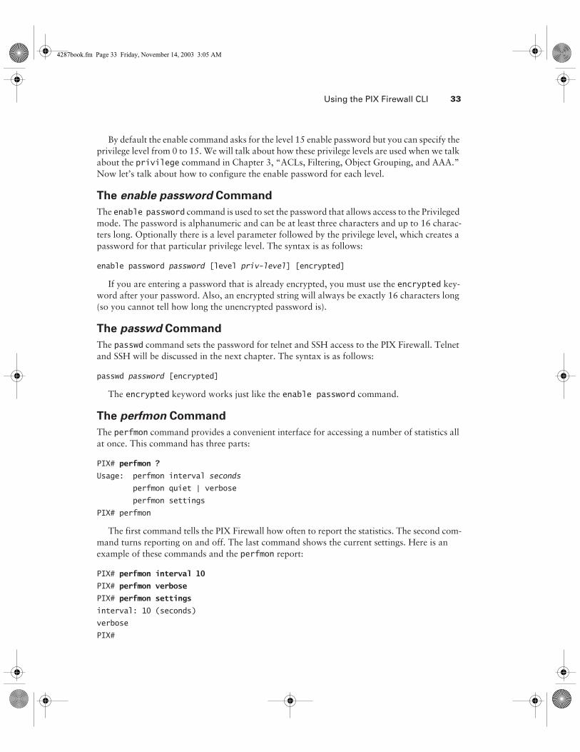
The perfmon Command
The perfmon command provides a convenient interface for accessing a number of statistics all at once. This command has three parts:
PIX# perfmon ?
Usage: perfmon interval seconds
perfmon quiet | verbose
perfmon settings
PIX# perfmon
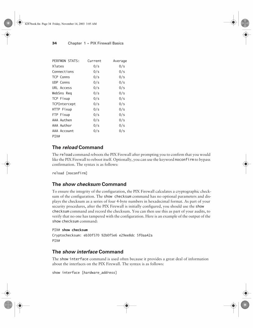
The first command tells the PIX Firewall how often to report the statistics. The second com-mand turns reporting on and off. The last command shows the current settings. Here is an example of these commands and the perfmon report:
PIX# perfmon interval 10
PIX# perfmon verbose
PIX# perfmon settings
interval: 10 (seconds)
verbose
PIX#
4287book.fm Page 33 Friday, November 14, 2003 3:05 AM
34 Chapter 1 � PIX Firewall Basics
PERFMON STATS: Current Average
Xlates 0/s 0/s
Connections 0/s 0/s
TCP Conns 0/s 0/s
UDP Conns 0/s 0/s
URL Access 0/s 0/s
WebSns Req 0/s 0/s
TCP Fixup 0/s 0/s
TCPIntercept 0/s 0/s
HTTP Fixup 0/s 0/s
FTP Fixup 0/s 0/s
AAA Authen 0/s 0/s
AAA Author 0/s 0/s
AAA Account 0/s 0/s
PIX#
The reload Command
The reload command reboots the PIX Firewall after prompting you to confirm that you would like the PIX Firewall to reboot itself. Optionally, you can use the keyword noconfirm to bypass confirmation. The syntax is as follows:
reload [noconfirm]
The show checksum Command
To ensure the integrity of the configuration, the PIX Firewall calculates a cryptographic check-sum of the configuration. The show checksum command has no optional parameters and dis-plays the checksum as a series of four 4-byte numbers in hexadecimal format. As part of your security procedures, after the PIX Firewall is initially configured, you should use the show checksum command and record the checksum. You can then use this as part of your audits, to verify that no one has tampered with the configuration. Here is an example of the output of the show checksum command:
PIX# show checksum
Cryptochecksum: eb30f570 92b0f5e6 e29ee8dc 5f0aa42a
PIX#
The show interface Command
The show interface command is used often because it provides a great deal of information about the interfaces on the PIX Firewall. The syntax is as follows:
show interface [hardware_address]
4287book.fm Page 34 Friday, November 14, 2003 3:05 AM
Using the PIX Firewall CLI 35
If the optional hardware address is given, the output is limited to information about the address specified; otherwise, information is displayed about all interfaces.
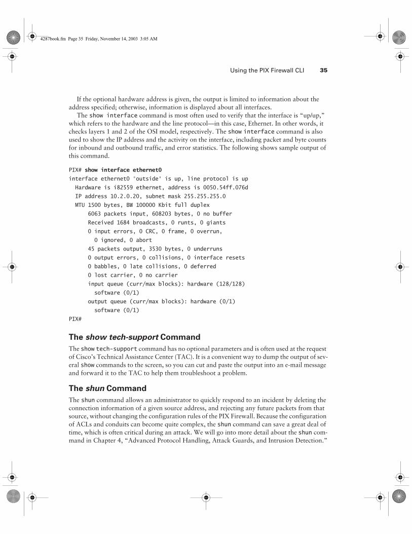
The show interface command is most often used to verify that the interface is “up/up,” which refers to the hardware and the line protocol—in this case, Ethernet. In other words, it checks layers 1 and 2 of the OSI model, respectively. The show interface command is also used to show the IP address and the activity on the interface, including packet and byte counts for inbound and outbound traffic, and error statistics. The following shows sample output of this command.
PIX# show interface ethernet0
interface ethernet0 "outside" is up, line protocol is up
Hardware is i82559 ethernet, address is 0050.54ff.076d
IP address 10.2.0.20, subnet mask 255.255.255.0
MTU 1500 bytes, BW 100000 Kbit full duplex
6063 packets input, 608203 bytes, 0 no buffer
Received 1684 broadcasts, 0 runts, 0 giants
0 input errors, 0 CRC, 0 frame, 0 overrun,
0 ignored, 0 abort
45 packets output, 3530 bytes, 0 underruns
0 output errors, 0 collisions, 0 interface resets
0 babbles, 0 late collisions, 0 deferred
0 lost carrier, 0 no carrier
input queue (curr/max blocks): hardware (128/128)
software (0/1)
output queue (curr/max blocks): hardware (0/1)
software (0/1)
PIX#
The show tech-support Command
The show tech-support command has no optional parameters and is often used at the request of Cisco’s Technical Assistance Center (TAC). It is a convenient way to dump the output of sev-eral show commands to the screen, so you can cut and paste the output into an e-mail message and forward it to the TAC to help them troubleshoot a problem.
The shun Command
The shun command allows an administrator to quickly respond to an incident by deleting the connection information of a given source address, and rejecting any future packets from that source, without changing the configuration rules of the PIX Firewall. Because the configuration of ACLs and conduits can become quite complex, the shun command can save a great deal of time, which is often critical during an attack. We will go into more detail about the shun com-mand in Chapter 4, “Advanced Protocol Handling, Attack Guards, and Intrusion Detection.”
4287book.fm Page 35 Friday, November 14, 2003 3:05 AM
36 Chapter 1 � PIX Firewall Basics
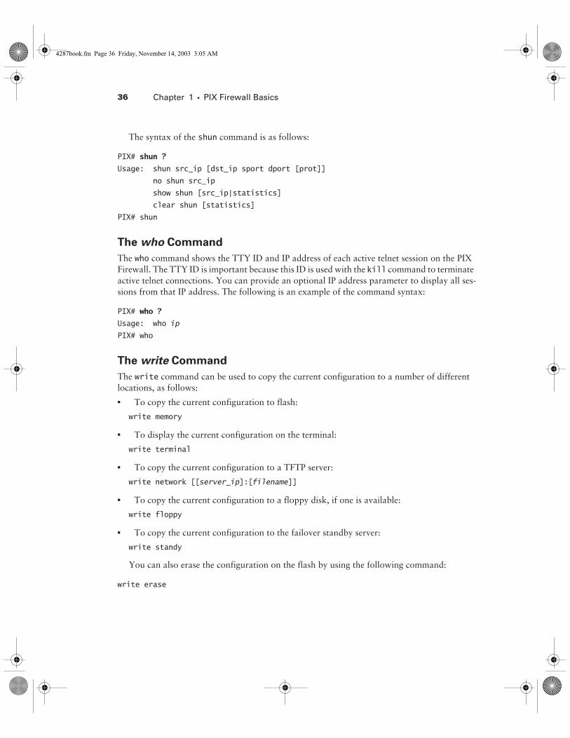
The syntax of the shun command is as follows:
PIX# shun ?
Usage: shun src_ip [dst_ip sport dport [prot]]
no shun src_ip
show shun [src_ip|statistics]
clear shun [statistics]
PIX# shun
The who Command
The who command shows the TTY ID and IP address of each active telnet session on the PIX Firewall. The TTY ID is important because this ID is used with the kill command to terminate active telnet connections. You can provide an optional IP address parameter to display all ses-sions from that IP address. The following is an example of the command syntax:
PIX# who ?
Usage: who ip
PIX# who
The write Command
The write command can be used to copy the current configuration to a number of different locations, as follows:� To copy the current configuration to flash:
write memory
� To display the current configuration on the terminal:
write terminal
� To copy the current configuration to a TFTP server:
write network [[server_ip]:[filename]]
� To copy the current configuration to a floppy disk, if one is available:
write floppy
� To copy the current configuration to the failover standby server:
write standy
You can also erase the configuration on the flash by using the following command:
write erase
4287book.fm Page 36 Friday, November 14, 2003 3:05 AM
Exam Essentials 37
The commands we covered in this section will get you started configuring your PIX Firewall. You will refer back to this section often because PIX Firewall administrators use these com-mands almost daily.
SummaryThis chapter began by defining the term firewall and explaining that the role of a firewall is to protect the network at the perimeter from outside attacks. We then looked at the three common firewall technologies in use today:� Packet-filtering firewalls use rules to deny packets based on the content of the headers. � Application proxies are layer 7–aware programs that communicate with systems on
untrusted networks on behalf of hosts in the trusted network. � Stateful firewalls permit or deny packets based on other packets, typically on a session
basis.
Next, we focused on the PIX Firewall where we examined the unique hardware and software components in a PIX Firewall and how they operate together to provide a formidable security solution. We then introduced the Firewall Service Module (FWSM), which runs the PIX Fire-wall operating system, and how to set up the module to work with both Cisco IOS and CatOS-based switches.
Finally, we covered the PIX Firewall CLI (command-line interface) and the common com-mands used in the day-to-day operation and management of the PIX Firewall.
Now that you have a basic understanding of firewalls, and the operation of the PIX Firewall specifically, this knowledge will provide a foundation for the advanced topics in later chapters.
Exam EssentialsKnow what the PIX Firewall protects against and what it doesn’t protect against. Under-stand the concept of a network’s perimeter. Understand the types of attacks and which ones can be detected and defeated by firewalls.
Understand the difference between translation slots, connection slots, and the xlate table.Be able to describe the purpose of each of these components. Know when they are created and where they exist.
Know how to describe a modern screened subnet, or DMZ. Understand why DMZs exist and their advantages and disadvantages. Be able to describe the flow of information in and out of a DMZ.
4287book.fm Page 37 Friday, November 14, 2003 3:05 AM

38 Chapter 1 � PIX Firewall Basics
Remember the differences between the various firewall technologies. Describe the operation of application proxies, packet filters, and stateful firewalls. Identify the advantages and disad-vantages of each type.
Understand the FWSM You need to be able to describe the features of the FWSM, the differ-ences it has from a stand-alone PIX Firewall, and the commands to configure the module for both Cisco IOS– and CatOS-based switches.
Know the different modes of the CLI. Distinguish between the User mode, Privileged mode, and Configuration mode on the PIX Firewall operating system CLI. Know how to get to each mode and what passwords are required.
Know how to use the show commands. Describe the output of common show commands. Know which command is the most appropriate for displaying various types of information.
Key TermsBefore you take the exam, be certain you are familiar with the following terms:
application proxies packet-filtering firewalls
connection slots proxy servers
defense in depth screened subnet
DMZ secure VLAN interface
firewall stateful firewalls
inside interface translation slot
Network Management Processor xlate table
outside interface
4287book.fm Page 38 Friday, November 14, 2003 3:05 AM

Review Questions 39
Review Questions1. You configure a PIX Firewall to block all traffic except HTTP. Later, you decide to test the fire-
wall by telneting into an internal server from the outside network. To your surprise, the telnet is successful! Which of the following could not be an explanation for this?
A. There is an alternative path into the network, bypassing the PIX Firewall.
B. You have misconfigured the PIX Firewall.
C. Since you are the administrator, the PIX Firewall permitted your telnet session.
D. The configuration of the PIX Firewall has been changed since you last configured it.
2. You configure two static NAT translations on a PIX Firewall. How many translation slots and connection slots will this generate in the xlate table?
A. 2 translation slots, 2 connection slots
B. 2 translation slots, 0 connection slots
C. 0 translation slots, 2 connection slots
D. 0 translation slots, 0 connection slots
3. You have two workstations on the inside network and a server on the outside network of a PIX Firewall. You open a Web browser on each of the workstations and point it to the server. You also telnet from one workstation to the server. How many connection slots and translation slots are in the xlate table of the PIX Firewall?
A. 2 translation slots, 3 connection slots
B. 3 translation slots, 2 connection slots
C. 1 translation slot, 5 connection slots
D. 1 translation slot, 6 connection slots
4. Users have started complaining about slow network response on traffic that flows across a PIX Firewall that you administer. Which command would you use to quickly gather performance statistics on the firewall?
A. show performance
B. show CPU
C. perfmon
D. statistics
5. How many Firewall Service Modules do you need to install in the 7600 Series router if you need to have 12Gbps of firewall throughput?
A. One
B. Three
C. Five
D. Two
4287book.fm Page 39 Friday, November 14, 2003 3:05 AM

40 Chapter 1 � PIX Firewall Basics
6. You want to allow telnet access to a server but prevent users from issuing commands that delete files. Which type of firewall would be the most appropriate?
A. Packet filtering
B. Application proxy
C. Stateful inspection
D. Class III
7. You have been asked to design a network where performance is the foremost priority. Which type of firewall would you employ?
A. Packet filtering
B. Application proxy
C. Stateful inspection
D. Class III
8. Which of the following commands will display the statistics of a single interface?
A. show interface
B. show interface outside
C. show interface 1
D. show interface ethernet1
9. On the PIX 535, in which slots can the VPN accelerator (PIX-VPN-ACCEL) and four-port Ethernet (PIX-4FE) card be placed? (Choose all that apply.)
A. 32-bit/66Mhz
B. 32-bit/32Mhz
C. 64-bit/33Mhz
D. 64-bit-66Mhz
10. How many interfaces are available on the PIX 501 Firewall?
A. One 10BaseT port and a four-port 100BaseTX switch
B. Two 10BaseT ports
C. Three 100BaseTX ports
D. Six 100BaseTX ports
4287book.fm Page 40 Friday, November 14, 2003 3:05 AM
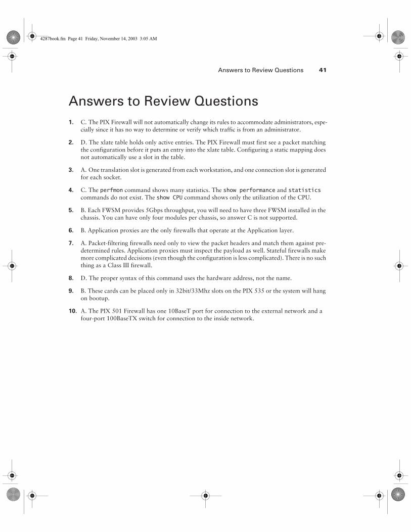
Answers to Review Questions 41
Answers to Review Questions1. C. The PIX Firewall will not automatically change its rules to accommodate administrators, espe-
cially since it has no way to determine or verify which traffic is from an administrator.
2. D. The xlate table holds only active entries. The PIX Firewall must first see a packet matching the configuration before it puts an entry into the xlate table. Configuring a static mapping does not automatically use a slot in the table.
3. A. One translation slot is generated from each workstation, and one connection slot is generated for each socket.
4. C. The perfmon command shows many statistics. The show performance and statistics commands do not exist. The show CPU command shows only the utilization of the CPU.
5. B. Each FWSM provides 5Gbps throughput, you will need to have three FWSM installed in the chassis. You can have only four modules per chassis, so answer C is not supported.
6. B. Application proxies are the only firewalls that operate at the Application layer.
7. A. Packet-filtering firewalls need only to view the packet headers and match them against pre-determined rules. Application proxies must inspect the payload as well. Stateful firewalls make more complicated decisions (even though the configuration is less complicated). There is no such thing as a Class III firewall.
8. D. The proper syntax of this command uses the hardware address, not the name.
9. B. These cards can be placed only in 32bit/33Mhz slots on the PIX 535 or the system will hang on bootup.
10. A. The PIX 501 Firewall has one 10BaseT port for connection to the external network and a four-port 100BaseTX switch for connection to the inside network.
4287book.fm Page 41 Friday, November 14, 2003 3:05 AM

4287book.fm Page 42 Friday, November 14, 2003 3:05 AM