Cisco SD-WAN - techfridays.rrc-academy.com
129
Cisco SD-WAN
Transcript of Cisco SD-WAN - techfridays.rrc-academy.com

Cisco SD-WAN

ScheduleDay 1• 09.00 – 10.20 – Session 1
• 10.20 – 10.40 – Break
• 10.40 – 11.40 – Session 2
Day 2• 09.00 – 10.30 – Session 1
• 10.30 – 10.50 – Break
• 10.50 – 12.30 – Session 2
Day 3• 09.00 – 10.20 – Session 1
• 10.20 – 10.30 – Break 1
• 10.30 – 12.00 – Test Session
• 12.00 – 12.10 – Break 2
• 12.10 – 13.00 – Test Session Wrap-Up
Day 1• Введение в Cisco SD-WAN
• Компоненты Cisco SD-WAN.
• Построение Overlay-сети. Протокол OMP
• Развертывание компонентов
Day 2• Политики SD-WAN. Control and Data Policies
• Политики SD-WAN. Advanced Policies. AAR
• SD-WAN Security
Day 3• Администрирование и мониторинг
• Миграция на Cisco SD-WAN


SD-WAN Use Cases

SD-WAN use cases
1
2
3
4 SaaS optimization
Extend SD-WAN to public clouds
One user interface across branch, cloud and colocation
5
Segmentation, zero touch provisioningand automation
Improve application experience
Secure Direct Internet Access (DIA)

Segmentation• Security Zoning
• Compliance
• Guest Wi-Fi
• Multi-Tenancy
• Extranet
Full- Mesh Hub-and-Spoke Any Topology
Per-VPN Topology
WAN Edge
VPN 1
VPN 2
VPN 3
SD- WAN
IPSec
Tunnel
WAN
Edge

On-Boarding example for WAN Edge
MPLS Internet PnP Servers
Configure Device
Template and attach to
the router in vManage
1
3
4
The router contacts a DHCP server and
receives its IP address from the server.
2
SD-WAN Controllers

Automation and Simplified Management
REST NETCONF Syslog Flow ExportSNMP CLI Linux Shell
Power Tools
Single Pane Of Glass Operations Rich Analytics
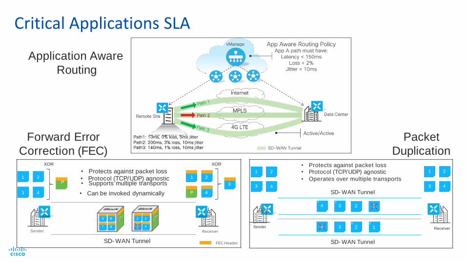
Critical Applications SLA
XOR
• Protects against packet loss• Protocol (TCP/UDP) agnostic
P • Supports multiple transports
XOR
1 2 1 2
3
3 4 • Can be invoked dynamically
5 6 1 2
7 8 3 4
Sender
SD- WAN Tunnel
P 4
Receiver
FEC Header
Forward Error
Correction (FEC)
1 2
4
• Protects against packet loss• Protocol (TCP/UDP) agnostic
• Operates over multiple transports
SD- WAN Tunnel
D D
4 3 2 1
D D
4 3 2 1
SD- WAN Tunnel
1
3
2
4
Receiver
3
Sender
Packet
Duplication
Application Aware
Routing

TCP Optimization
Problem:
• WAN Transport Link between two SD-WAN routers has high latency
Solution:
• Enable TCP Optimization for critical traffic between two SD-WAN sites
High latency
SD-WAN
LinkData CenterRemote Site

Powered By
Full stack branch
management for Lean IT
Powered By
Viptela
Flexible and sophisticated
with secure segmentation
and advanced routing
SD-WAN
Cisco SD-WAN Portfolio

SD-WANdeployment options

Cisco SD-WAN Platform Positioning
Pure Play SD-WAN
Transport Independence,
Cloud Management & Analytics
Integrated Services SD-WAN
Interface Flexibility,
Rich Services
Multi- Domain*
(DC, Campus)
Embedded
Security
ZBFW+ Cloud
Security
Integrated Voice*
*Roadmap for FY211 On select ISR Product family
Viptela OS: ISR 1100-4G, ISR 1100-6G, vEdge 2000
IOS-XE SD-WAN OS: ISR1, ASR, CSR
VR
Fand
TunnelS
cale
,T
hro
ughput
Voice OptimizationCloud onRamp for
IaaS and SaaS
Cloud onRamp for
Colocation
Adv. Cloud
Security*
ZBFW + Cloud
SecurityVoice Optimization
Cloud onRamp for
IaaS and SaaS
One user interface across branch, cloud and colocation

SD-WAN Portfolio with New Platforms
ASR 1000 Fixed
• High-performance services with
hardware assist
vEdge 5000
• WAN and voice module flexibility
• On-box Security
• Compute with UCS-E
• Slot Modularity, RPS(optional)
• 10GE option
ISR 1000
• Integrated wired and wireless access
• LTE Advanced
• VDSL2,ADSL2/2+
Virtualized
• Service chaining virtual functions
• Options for WAN connectivity
• Open for 3rd party services & apps
• NFVIS Hypervisor
Cisco ENCS & CSPCSR 1000V
vEdge Cloud• Extend enterprise routing,
security & management to cloud
• Cisco DNA virtualization
Branch Aggregation
ISR1120 / 1160 ISR 4000
vEdge 2000
• 4G WWAN pluggable flexibility(CAT4/6/18)
• On-box Security
• RPS, PIM options • Modularity, RPS
(New 25 SKUs) ISR 4461Highest
performing ISR to- date
Inte
gra
ted
Se
rvic
es
IOS
XE
SD
-WA
N
Pu
reP
lay
VIP
TE
LA
OS ISR1100- 4G
• 4 GE WAN ports
ISR1100-4GLTE
• 4G LTE (CAT4)
ISR1100- 6G
• 6 WAN ports (4GE and 2 SFP)

SD-WANArchitecture

Cisco SD-WAN Architecture Overview
Data Center Campus Branch SOHO
4G/LTE
MPLS
Internet
Control Plane = vSmart(Containers or VMs)
Data Plane = WAN Edge(vEdge, Cisco ISR/ASR/ENCS,
Whitebox)
Management = vManage(Multi-tenant or Dedicated)
Orchestration = vBond
vManage
vSmart
WAN Edge
Orchestrator ZTP/PnP
APIs
Cloud
vAnalytics
Data Center Campus Branch SOHO
4G/LTE
MPLS
Internet
Orchestrator ZTP/PnP
Cloud
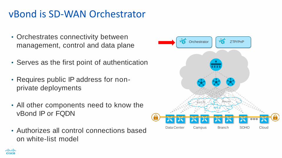
vBond is SD-WAN Orchestrator
• Orchestrates connectivity between
management, control and data plane
• Serves as the first point of authentication
• Requires public IP address for non-
private deployments
• All other components need to know the
vBond IP or FQDN
• Authorizes all control connections based
on white-list model

Data Center Campus Branch SOHO
4G/LTE
MPLS
Internet
Orchestrator ZTP/PnP
Cloud
vManage is NMS for SD-WAN
• Single-tenant or Multitenant
• Single pane of glass for Day 0, Day 1 and Day 2 operations
• Enables centralized provisioning andsimplifies changes
• Supports REST API, CLI, Syslog, SNMP, NETCONF
• Provides real time alerting
• Role Based Access Control

Data Center Campus Branch SOHO
4G/LTE
MPLS
Internet
Orchestrator ZTP/PnP
Cloud
vSmart is Centralized Control Plane
• Implements control plane policies, such as service chaining, traffic engineering and per-VPN topology
• Reduces complexity of the entire network
• Establishes peering with all WAN Edges, distributes connectivity and security context

Controllers’ Deployment Models
Enterprise IT
vManage
vSmart vBond
Private
Cloud
Deploy
vManage
vSmart vBond
MSP
Cloud
Deploy
Cisco Cloud Ops MSP Ops Team
vManage
vSmart vBond
Cisco
Cloud
Deploy

Validated Controller Scale
vManage:
2,000 Devices per-single instance
Max Production Deployment: 6 instances
vSmart:
5,400 Connections per-single vSmart Max Production
Deployment: 20 vSmarts
vBond:
1,500 Connections per-single vBond Max Production
Deployment: 6 vBonds

WAN Edge is your SD-WAN Data Plane
• Provides secure data plane with remote WAN Edge routers
• Establishes secure control plane withvSmart controllers
• Implements data plane and application aware routing policies
• Exports performance statistics
• Physical or Virtual form factor Data Center Campus Branch SOHO
4G/LTE
MPLS
Internet
Orchestrator ZTP/PnP
Cloud

• Transient connection
• FQDN must be configured
• DNS load sharing
• vEdge require at least onevBond
• No new vEdge routers can join if vBonds fail or are unreachable
Describe vBond Redundancy

• All vManage servers in a cluster act as active/active nodes for a region.
• For redundancy between regions, vManage operate in active/standby.
• Loss of vManage has no impact on fabric operation.
Describe vManage Redundancy

• Managing more than 2000 vEdge routers
• Distributing NMS service loads
• Providing high availability and redundancy for fault tolerance
Describe vManage Redundancy (Cont.)
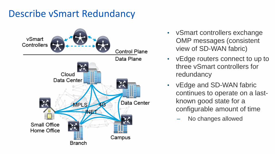
• vSmart controllers exchange OMP messages (consistent view of SD-WAN fabric)
• vEdge routers connect to up to three vSmart controllers for redundancy
• vEdge and SD-WAN fabric continues to operate on a last-known good state for a configurable amount of time
– No changes allowed
Describe vSmart Redundancy

• Redundant vEdge routers
• OSPF and BGP between vEdge routers and site routers
• Two-way redistributionbetween OMP and OSPF/BGP
• ECMP available for remote destinations SD-WAN fabric
Describe Site Design

• Redundant vEdge routers
• VRRP between vEdge routers (per VLAN)
• VRRP Active router respondsto ARP requests
Describe Site Design (Cont.)

SD-WAN Fabric

Unified Control Plane
• Overlay Management Protocol (OMP)
• TCP based extensible control plane protocol
• Runs between WAN Edge routers and
vSmart controllers and between the
vSmart controllers
• Inside authenticated TLS/DTLS
connections
• Advertises control plane context and policies
• Dramatically lowers control plane complexity
and raises overall solution scale
vSmart vSmart
vSmart
WAN Edge WAN Edge

Data Plane Establishment
OMP IPSec Tunnel
WAN Edge
WAN Edge
WAN Edge
WAN Edge
Routes and encryption keys
are advertised to vSmarts in
OMP updates
Local Routes- Local prefixes (OSPF/BGP)- SD-WAN tunnel endpoints (TLOCs)
Security Context- IPSec Encryption Keys
vSmarts advertise routes and
encryption keys to WAN
Edges in OMP updates
INETMPLS
WAN Edge
Transport Locator (TLOC)
vSmart
SD-WAN fabric
between tunnel
endpoints
IPsec
IPsec
IPsec
Fabric Routing:
<prefix> via

TCP-based extensible control plane protocol
Runs between vEdge routers and vSmart controllers and
between the vSmart controllers
Inside permanent TLS/DTLS connections
Automatically enabled on bring-up
vSmarts create full mesh of OMP peers
vEdge routers are not required to peer with all vSmarts.
vSmart1 vSmart3
vSmart2
vEdge vEdge
OMP Peers
Peer Peer Hostname Type Site ID State
1.1.1.53 vSmart1 vsmart 53 up
1.1.1.54 vSmart2 vsmart 54 up
Overlay Management Protocol (OMP)
INETMPLS
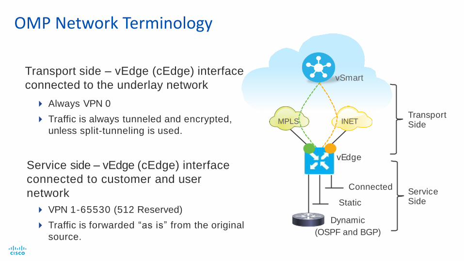
OMP Network Terminology
Always VPN 0
Traffic is always tunneled and encrypted,
unless split-tunneling is used.
Service side – vEdge (cEdge) interface
connected to customer and user
network
VPN 1-65530 (512 Reserved)
Traffic is forwarded “as is” from the original
source.
vSmart
Connected
Static
Dynamic
(OSPF and BGP)
vEdge
Service Side
Transport Side
Transport side – vEdge (cEdge) interface
connected to the underlay network

OMP Network Terminology (Cont.)
System-IP: IPv4 address (nonrouted identifier)
Color: type of WAN interface on the local vEdge
Private TLOC: IP address on the interface located inside NAT
Public TLOC: IP address on the interface located outside of NAT
Private and public are the same if the connection is not subject to NAT.
OMP routes, service side routes, and vRoutes: routes learned and connected on
the service side
Routes are tagged with attributes as the OMP picks up the routes.
TLOC (transport locators): collection of entities making up a transport side
connection

System-IP: Unique identifier of an OMP endpoint; has the following
characteristics:
32-bit dot decimal notation (an IPv4 address)
Logically, a VPN 0 loopback interface, referred to as "system"
Organization-Name: Defines the organizational unit (OU) to match in the
certification authorization (CA) process:
The OU is carried in both directions for authentication control and vEdge nodes.
Site-ID: Identifies the source location of an advertised prefix:
Site-ID is configured on every vEdge.
Site-ID does not have to be unique, but it then assumes the same location.
OMP Network Terminology

OMP IPsec Tunnel
vEdge
vEdge
vEdge
vEdge
vEdge
Transport Locator (TLOC)
Local TLOCs
(System IP, Color, Encap)
TLOCs are advertised to
vSmarts in TLOC routes
vSmarts advertise TLOCs
to vEdges in TLOC routes
Transport Locators
SD-WAN Fabric
with TLOCs as
Tunnel Endpoints
IPsec
IPsec
IPsec MPLS INET
TLOCs

TLOCs and Colors
• The specific color that is used is categorized as private or public.
• Private colors [mpls, private1-6, metro-ethernet]
• All other colors are public [red, blue, … , public-ethernet, … ]
• Private versus public color is highly significant.
• The color setting applies to the following:
• vEdge to vEdge communication
• vEdge to controller communication
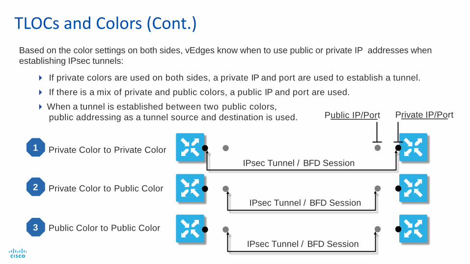
TLOCs and Colors (Cont.)
If private colors are used on both sides, a private IP and port are used to establish a tunnel.
If there is a mix of private and public colors, a public IP and port are used.
When a tunnel is established between two public colors,
public addressing as a tunnel source and destination is used.
Private Color to Private Color
Private Color to Public Color
1
2
Public IP/Port Private IP/Port
IPsec Tunnel / BFD Session
3 Public Color to Public Color
IPsec Tunnel / BFD Session
IPsec Tunnel / BFD Session
Based on the color settings on both sides, vEdges know when to use public or private IP addresses when
establishing IPsec tunnels:

vEdge vEdge
T3 T4 T1 T2
T3
T4
T1
T2
T1
T1
T3 T2
T4 T2
T4
T3
Internet2
T1, T3—Internet1 ColorT2, T4—Internet2 Color
T1 T4 T2 T3
Color restrict prevents attempt to
establish IPsec tunnel to TLOCs with
different color.
T1 T3 T2 T4
vEdge vEdge
T3 T4 T1 T2Internet
MPLS
T1, T3 – Internet Color T2, T4 – MPLS Color
T1
T2
Internet1
T3
T4
TLOCs and Colors (Cont.)

• Service side routing protocols:
– Static, OSPF, BGP
• OMP routing across the overlay:
– OMP routes (service side)
– TLOC routes
– Network service routes
• OMP: path selection, loop avoidance, policy implementation
Overlay Routing

• OMP routes learned from local service side
• OMP routes advertised to vSmart
• OMP route attributes:
– TLOC
– Site-ID
– Label
– VPN-ID
– Tag
– Preference
– Originator
Overlay Routing: OMP Routes

• TLOCs connect locations to physical networks
• TLOCs advertised to vSmart
• TLOC route attributes:
– Site-ID
– Color
– Encapsulation
– Public/Private IPs, Ports
– BFD
– Tag
– Weight
Overlay Routing: TLOC Routes

• Routes advertising network services:
– Firewall
– IDS/IPS
• Routes advertised to vSmart
• Attributes:
– VPN-ID
– Service-ID
– Label
– Originator
– TLOC
Overlay Routing: Network Service Routes
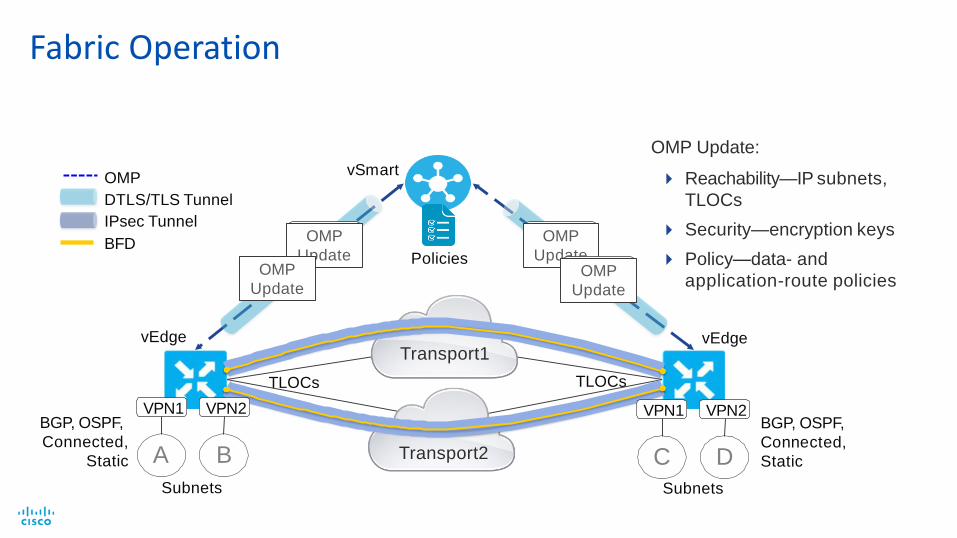
Fabric Operation
Reachability—IP subnets,
TLOCs
Security—encryption keys
Policy—data- and
application-route policies
port1
BGP, OSPF,
Connected,
Static
OMP
DTLS/TLS Tunnel
IPsec Tunnel
BFD
VPN1 VPN2 VPN1 VPN2BGP, OSPF,
Connected,
Static
vSmart
OMP
Update
OMP
Update
vEdge vEdge
A B
Subnets
C D
Subnets
TLOCs TLOCs
PoliciesOMP
UpdateOMP
Update
Transport1
Transport2
OMP Update:

Data Plane Liveliness and Quality
WAN Edge WAN Edge
WAN Edge
WAN Edge WAN Edge
• Bidirectional Forwarding Detection (BFD)
• Path liveliness and quality measurement
- Up/Down, loss/latency/jitter, IPSec tunnel MTU
• Runs between all WAN Edge routers in the topology- Inside SD-WAN tunnels
- Across all transports
- Operates in echo mode
- Automatically invoked at SD-WAN tunnel
establishment
- Cannot be disabled
• Uses hello (up/down) interval, poll (app-aware)
interval and multiplier for detection- Fully customizable per-WAN Edge, per-transport
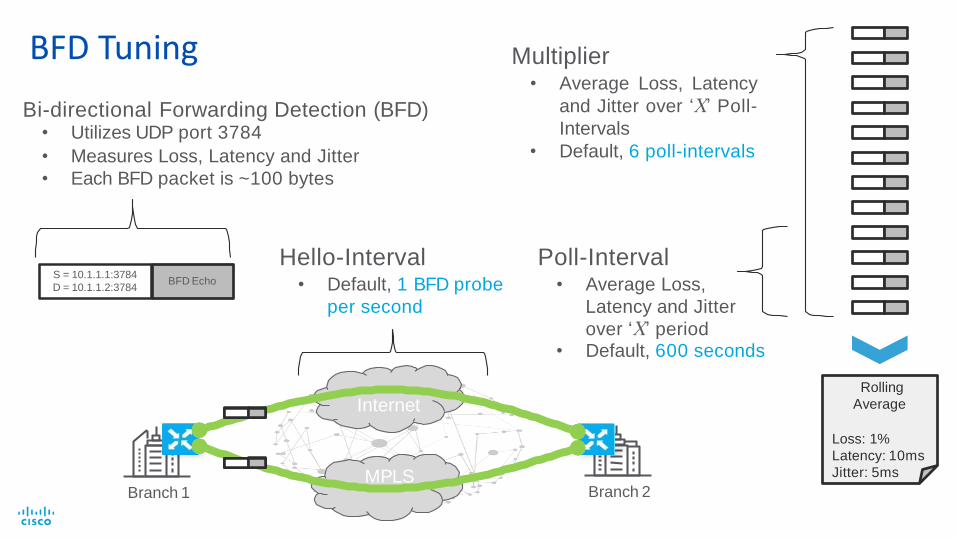
BFD Tuning
Bi-directional Forwarding Detection (BFD)• Utilizes UDP port 3784
• Measures Loss, Latency and Jitter
• Each BFD packet is ~100 bytes
S = 10.1.1.1:3784
D = 10.1.1.2:3784BFD Echo
Poll-Interval• Average Loss,
Latency and Jitter
over ‘X’ period• Default, 600 seconds
Multiplier• Average Loss, Latency
and Jitter over ‘X’ Poll-
Intervals
• Default, 6 poll-intervals
Rolling
Average
Loss: 1%
Latency: 10ms
Jitter: 5ms
Internet
MPLSBranch 1 Branch 2
Hello-Interval• Default, 1 BFD probe
per second

BFD Example
BFD = 1s (Default)
Number of Intervals = 3 (Default=6)
Poll Interval = 600 sec (Default)
600 Samples 600 Samples 600 Samples
AAR Policy:
Change path if SLA is not met:
20 % loss
100 ms latency
100 ms jitter
600 Samples
300/600 loss
BFD measurement = 900/1800 = 50 % loss
If loss > 20 %
Yes, loss = 33,3 %
Action = reroute
600 Samples
300/600 loss
If loss > 20 %
50% loss
introduced
No, loss = 0%
600 Samples
300/600 loss
BFD measurement = 600/1800 = 33,3 % loss
If loss > 20 %
No, loss = 16,6%
Reroute after
20 minutes(2 intervals)
Convergence after
30 minutes(3 intervals)
BFD measurement = 300/1800 = 16,6 % loss
BFD measurement = 0 % loss

BFD Recommendations
Aggressive (POC):
• Hello Interval: 1 second (Default)
• Multiplier: 2 intervals
• Poll Interval: 4 seconds
Max 8 seconds brownout detection!
Moderate:
• Hello Interval: 1 second (Default)
• Multiplier: 3 intervals
• Poll Interval: 180 seconds
Max 9 minutes brownout detection!
Conservative:
• Hello Interval: 1 second (Default)
• Multiplier: 6 intervals (Default)
• Poll Interval: 10 minutes (Default)
Max 60 minutes brownout detection!
Note: Tuning is good for POC. For production, keep the default values unless you have specific requirements.
You can lower the tunnel multiplier to detect tunnel down conditions (default is 7 consecutive missed BFDs).
You can reduce Hello Interval to reach sub second failovers.
Enable the OMP Backup Path feature for pre-calculated backup path
WAN Edge appliances are scale tested based on default values. Tuning BFD parameters too low will increase the
CPU burden on the appliance and, hence, lower scalability.

Common Data Plane Communication
Per-Session Load Sharing
Active/Active
INETMPLS
Default
Per-Session Weighted
Active/Active
INETMPLS
DeviceConfigurable
Application Pinning
Active/Standby
INETMPLS
PolicyEnforced
Application Aware Routing
SLA Compliant
MPLS INET
SLA SLA
PolicyEnforced

SD-WAN Help-Desk
SD-WANHelp- Desk
• Ensure successful adoption of SD-WAN with
TME/TSA assistance delivered through a help-
desk for customers and partners
o High Level Design Review Consultation
o Deployment consultation
• Requests submitted through email
• Technical resources enabled on latest releases
and implementation best practices
Email [email protected] for design requests
Call To Action
Learn more:
• eBook ”Cisco SD-WAN. Cloud scale architecture” (see next slide) cs.co/sdwanbook
Practice:
• Complete dCloud SD-WAN Lab “Cisco 4D SD-WAN (Viptela)”

Controller Provisioning

1. Obtain software and verify system requirements.
2. Deploy the Open Virtualization Format (OVF) template.
3. Perform the installation and initial configuration (hostname,
Network Time Protocol [NTP]).
4. Configure System-IP, Site-ID, and Organizational Name.
5. If you use a local CA, install root CA chain and resynchronize
the vManage database.
vManage Installation Process

Verifying vManage System Requirements
Only Solid State Drive (SSD)–based volumes are officially supported.
Sites vCPUs RAM
OS
Volume Database Volume Bandwidth vNICs
1-250 16 32 GB 16 GB 500 GB,
1500 IOPS
25 Mbps 3
251-1000 32 64 GB 16 GB 1 TB,
3072 IOPS
100 Mbps 3
1001
or
more
32 64 GB 16 GB 1 TB,
3072 IOPS
150 Mbps 3
System requirements for vManage depend on the number of sites
to support, as follows:

Deploying OVF Template

Do not power on yet.
Deploying OVF Template (Cont.)

Adding Resources to the VM

Defining Disk Type and Specifying Capacity

Selecting Correct Virtual Drive Type

Adding a Network Interface
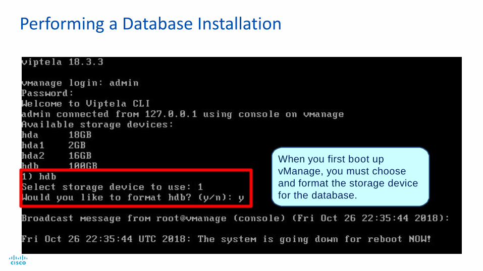
When you first boot up
vManage, you must choose
and format the storage device
for the database.
Performing a Database Installation
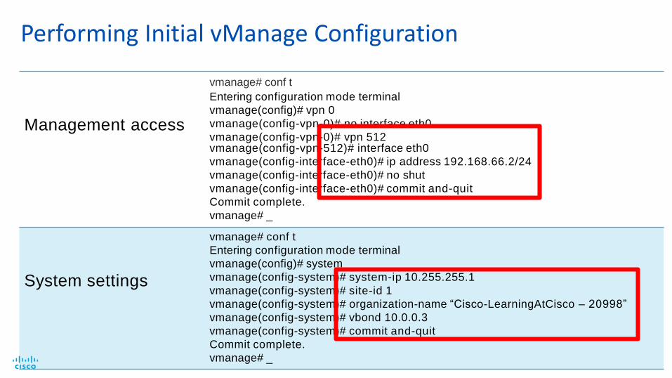
Management access
Performing Initial vManage Configuration
vmanage# conf t
Entering configuration mode terminal
vmanage(config)# vpn 0
vmanage(config-vpn-0)# no interface eth0
vmanage(config-vpn-0)# vpn 512vmanage(config-vpn-512)# interface eth0
vmanage(config-interface-eth0)# ip address 192.168.66.2/24
vmanage(config-interface-eth0)# no shut
vmanage(config-interface-eth0)# commit and-quit
Commit complete.
vmanage# _
System settings
vmanage# conf t
Entering configuration mode terminal
vmanage(config)# system
vmanage(config-system)# system-ip 10.255.255.1
vmanage(config-system)# site-id 1
vmanage(config-system)# organization-name “Cisco-LearningAtCisco – 20998”
vmanage(config-system)# vbond 10.0.0.3
vmanage(config-system)# commit and-quit
Commit complete.
vmanage# _
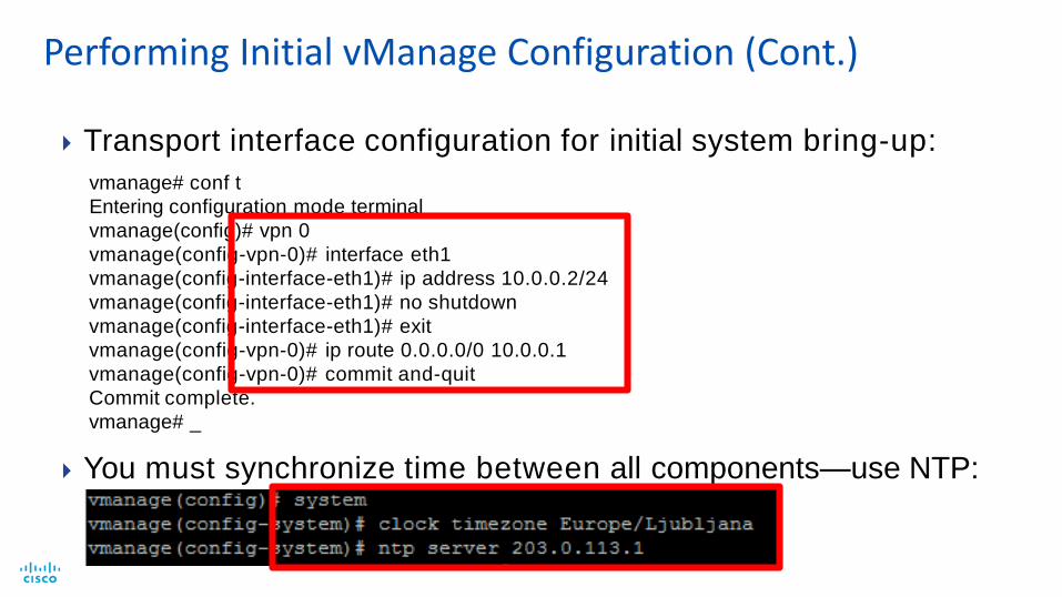
Transport interface configuration for initial system bring-up:
vmanage# conf t
Entering configuration mode terminal
vmanage(config)# vpn 0
vmanage(config-vpn-0)# interface eth1
vmanage(config-interface-eth1)# ip address 10.0.0.2/24
vmanage(config-interface-eth1)# no shutdown
vmanage(config-interface-eth1)# exit
vmanage(config-vpn-0)# ip route 0.0.0.0/0 10.0.0.1
vmanage(config-vpn-0)# commit and-quit
Commit complete.
vmanage# _
You must synchronize time between all components—use NTP:
Performing Initial vManage Configuration (Cont.)

Ensure that you include the full root CA certificate chain if you are
using subordinate CAs.
Transfer root CA to vManage by using SCP or any other tool:
root@CA:~/rootCA#scp ca.crt [email protected]:
Installing Local Root CA Chain - vManage

Import the root CA through the CLI.
Synchronize the vManage database by using an API call (required step):
https://<vmanage_ip>/dataservice/system/device/sync/rootcertchain
Installing Local Root CA Chain – vManage (Cont.)

Verify the installed root CA certificate: show certificate root-ca-chain
Installing Local Root CA Chain – vManage (Cont.)

Accessing Web Interface and System Settings

1. Obtain software and verify system requirements.
2. Deploy the OVF template.
3. Perform installation and initial configuration (hostname and NTP).
4. Configure System-IP, Site-ID, Organizational Name, and vBond local
role, and disable tunnel-interface.
5. If you are using a local CA, install the root CA chain.
vBond Installation Process

Only SSD-based volumes are officially supported.
Sites vCPUs RAM OS
Volume
Bandwidth vNICs
1-50 2 4 GB 8 GB 1 Mbps 2
51-250 2 4 GB 8 GB 2 Mbps 2
251-1000 2 4 GB 8 GB 5 Mbps 2
1001+ 4 8 GB 8 GB 10 Mbps 2
Verifying vBond System Requirements

The local keyword in the vbond command enables the vBond role.
Performing Initial vBond Configuration

You configure interfaces the same as on other devices:
VPN 512 = management
VPN 0 = transport
Example of enabling management access in VPN 512:
Performing Initial vBond Configuration (Cont.)

Strict separation of
management and control
plane enforces a strong
security-zone model:
Permits only control protocols
on the control interface (by
default, only the tunnels).
Permits only management
protocols (i.e., SSH and HTTP)
on the management interface.
You must loosen strict
separation during setup.Control
InterfaceManagement
Interface
Allow Only Management Protocols
VPN512VPN0
Allow Only VPN 0 Tunnels
Strong Zone – Based Security on Controllers

Disable tunnel interface for initial system bring-up.
Alternative approach: allow netconf service under tunnel interface.
Lower Transport Interface Security During Initial Bring-UP
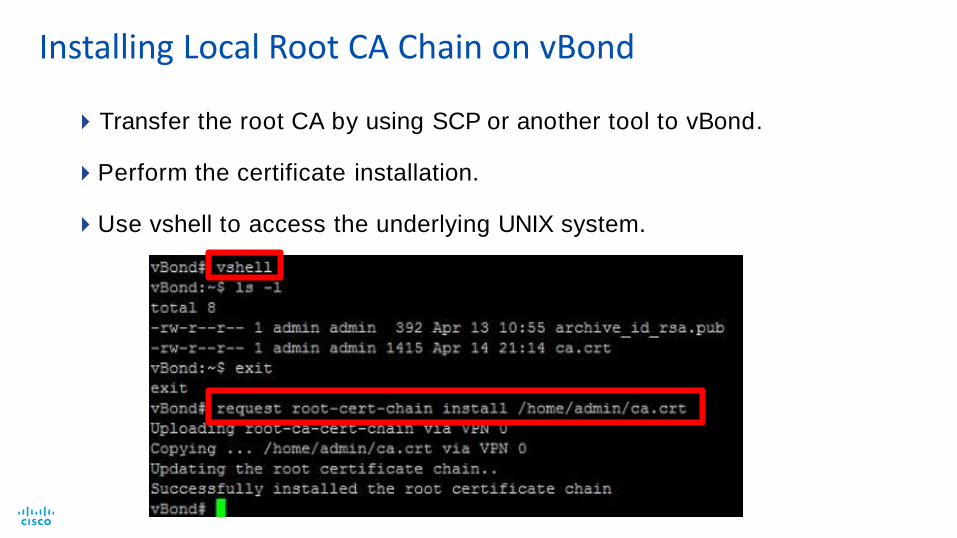
Transfer the root CA by using SCP or another tool to vBond.
Perform the certificate installation.
Use vshell to access the underlying UNIX system.
Installing Local Root CA Chain on vBond

1. Obtain software and verify system requirements.
2. Deploy the OVF template.
3. Perform installation and initial configuration (hostname and
NTP).
4. Configure System-IP, Site-ID, and Organizational Name.
5. If you are using a local CA, install the root CA chain.
Same procedure as vBond
vSmart Installation Process

Only SSD-based volumes are officially supported.
Sites vCPUs RAM OS Volume Bandwidt
h
vNICs
1-50 2 4 GB 16 GB 2 Mbps 2
51-250 4 6 GB 16 GB 5 Mbps 2
251-1000 4 16 GB 16 GB 7 Mbps 2
1001+ 8 16 GB 16 GB 10 Mbps 2
Verifying vSmart System Requirements

Using Enterprise CA
A customer’s existing CA infrastructure
Microsoft CA is most commonly used within enterprise environments.
A CA built only for testing:
XCA
TinyCA
OpenSSL
OpenSSL library is part of most Linux distributions by default.
Can be used for certificate generation, signing CSRs, etc.
If you use subordinate servers, make sure to export and import
the full root-ca chain.
Several options for local CA are as follows:

1. Create a custom OpenSSL
configuration file.
2. Specify paths for new certification,
database, serial numbers, and so
forth.
3. Describe the path to the private key
and certificate.
4. Specify validity (in days).
5. Specify the policy.
Setting Up a Local CA

ca.crt is our new root
certificate.
You must import the
root-ca certificate on all
controllers and vEdge
devices.
The -days parameter
sets the root-ca validity
to the desired length
(default is 30 days.)
Generating a Key and Self-Signed Certificate by Using OpenSSL

Adding vBond and vSmart to vManage

Generating CSRs
CSR (Certificate Signing Request) contains the information that
goes into the certificate that is sent to the CA for signing.
To enroll the controllers with the CA, you must generate a CSR
(Certificate Signing Request) and then transmit the CSR to the CA.
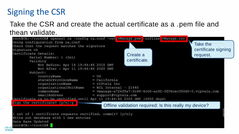
Signing the CSR
Take the
certificate signing
request.Create a
certificate.
Offline validation required: Is this really my device?
Take the CSR and create the actual certificate as a .pem file and
thean validate.

You can browse to and
select a certificate file for
installation.
Installing the Signed Certificate

When installing certificates (and for other processes as well), you can view the Task
View window to check the progress.
Click the Task View icon.
Monitoring Ongoing Tasks in Task View

Under the VPN 0 interface, enable
tunnel-interface configuration on all
three controllers.
vBond requires the following as well:
encapsulation ipsec
Configuring VPN 0 for Operation

On the vManage dashboard (top left menu icon), you should now see all
controllers up.
You see one Control Up in the Control Status field for each operational
vSmart.
Verifying Control Connections on the Dashboard

vBond and NAT Traversal in On-Premises Deployment
vBond vSmart vManage
MPLSInternet
DC Segment
Private IP/Port
Public IP/Port
Controllers can support hybrid
private or public transport
connections.
Private transport using private
IPs for communication. Prefix
advertised in private domain.
Public transport using public
IPs, generally assigned by
provider.
Multihomed vEdge capable of
supporting both models
concurrently.
Proper color assignment is
crucial.
DMZ
Controllers Accessible through Private and Public Transport

Firewall-Protecting Edge-Port Essentials
Summary of Ports Required
to vManage/vSmart: TCP – 23456 to
24156 (Destination Port)
Source IP = vEdge Routers
to vBond/ZTP: UDP – 12346 (Destination
Port)
Source IP = vEdge Routers
to other vEdge routers: UDP – 12346 to
12445 (Source Port)
Source IP/Port = vEdge Routers/12346-
12445
All connections
originate from
vEdge routers.
FW configuration infront of controllers:mirror image
vSmart1
IP ADDRESS
vManageIP ADDRESS
Outbound through the Firewall
to vManage/vSmart: UDP – 12346 to
12445 (Destination Port)
Source IP = vEdge Routers
vEdge2
Firewall
vEdge
vBond1
IP ADDRESS
UDP dst
12346
UDP dst (IPsec)
12346 to 12445
TCP dst
23456 - 24156
ztp.viptela.com
IP ADDRESS
TCP dst
23456 - 24156
UDP dst (IPsec) UDP dst (IPsec)
12346 to 12445 12346 to 12445
Ports listed here must be allowed through the firewall outbound only.

Validate means that the vEdge can connect without further human control.
If not checked, each device must be validated individually, so that the device can join the network.
Be careful with automatically validating, because devices get lost in transport or stolen.
Importing a WAN Edge List
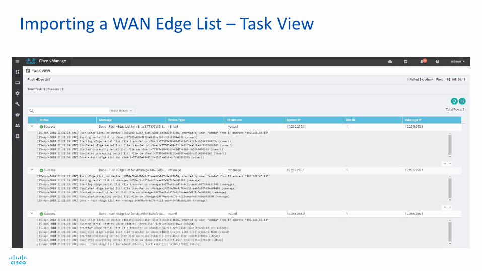
Importing a WAN Edge List – Task View
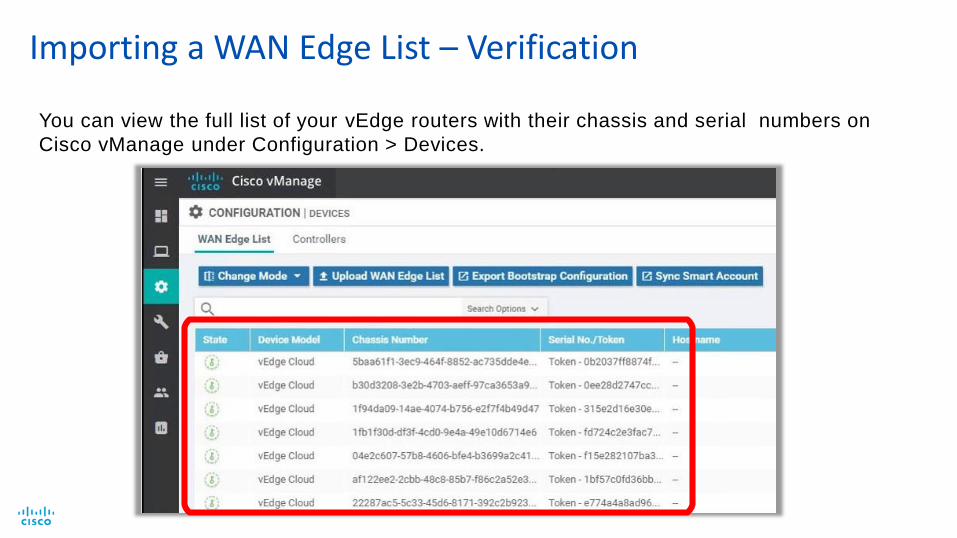
Importing a WAN Edge List – Verification
You can view the full list of your vEdge routers with their chassis and serial numbers on
Cisco vManage under Configuration > Devices.

Zero Touch Provisioning

Zero Touch Provisioning – vEdge HW Appliance
vEdge Router
• Public ZTP vBond can redirect
to cloud hosted or On-Prem
controllers.
• New devices are linked to
organization using the Smart
Account when placing order.
• Additional devices can be
associated with the customer
using the PnP Connect portal
• ZTP for vEdges can be
deployed also On-Prem
Controllers
Full Registration
and Configuration
1 23 4 5
Option1: DHCP on WAN interface
DNS to resolve ztp.viptela.com
Public or On-Prem
ZTP vBond
Option2: Discover local addressing via ARP
Google DNS: resolve ztp.viptela.com

Deploying cEdge Devices by Manually Upgrading
Perform cEdgemanual upgradeprerequisites.
Convert Cisco IOSXE Router into theSD-WAN Router
Perform initial router
configuration
Deploying cEdge devices through manual upgrade is a three- part
process.

Performing cEdge Manual Upgrade Prerequisites
2. Load the SD-WAN image to the Cisco IOS XE router (bootflash) by
using a file transfer protocol, such as SCP.
1) Preprovision the router in vManage (upload WAN Edge list).
You can preprovision the router in
vManage by using either method
Perform cEdge manual upgrade prerequisites as follows:

Converting the Cisco IOS XE Router to an SD-WAN Router
2. Reload the
router.
1. Set the boot
statement.

3. After the router reloads, execute the following command:
request platform software sdwan software reset
This command completely removes everything that is no SD-
WAN-related, including configuration files, all interfaces are
shut down, and another system reboot is triggered.
Converting the Cisco IOS XE Router to an SD-WAN Router (Cont.)

Performing Initial Configuration
After the PnP Discovery process is stopped, you can manually enroll the
new cEdge router.
After the router successfully reboots, stop the plug-and-play service by
using the pnpa service discovery stop command.

ZTP – Bootstraping With Configuration File
• Upon bootup, the router searches bootflash: or usbflash: for filename ciscosdwan.cfg.
• The config file with interface configuration, Root CA, Organization Name, vBond information, is fed into the PnP process.
• Supported only on SD-WAN IOS-XE (since 16.10).
<… output omitted …>
#cloud-boothook
system
personality
device-model
host-name
system-ip
site-id
organization-name
vedge
vedge-ISR-4321
WanEdge
10.255.255.121
21
"CLEUR 2020 BRKRST - 2559"console-baud-rate 9600
vbond 203.0.113.3 port 12346
!
!
interface GigabitEthernet0/0/0
no shutdown
ip address 198.0.51.10 255.255.255.0
exit
!
ip route 0.0.0.0 0.0.0.0 198.0.51.1
<… output omitted …>

Generating Bootstrap Configuration File
• Attach template to device placeholder
• Specify device specific variable values
• Generate bootstrap config
• Store it on bootflash: or usbflash: as ciscosdwan.cfg

Router Configuration
Router# config-transaction
Router(config)# system
Router(config-system)# host-name X
Router(config-system)# system-ip X
Router(config-system)# side-id X
Router(config-system)# vbond X
Router(config-system)# organization-name X
Router(config-system)# exit
Router(config)# interface TunnelX
Router(config-if)# ip unnumbered <WAN Physical>
Router(config-if)# tunnel source <WAN Physical>
Router(config-if)# tunnel mode sdwan
Router(config-if)# exit
Router(config)# sdwan
Router(config-sdwan)# interface GigabitEthernetX/X/X
Router(config-interface-GigabitEthernetX/X/X)# tunnel-interface
Router(config-tunnel-interface)# color X
Router(config-tunnel-interface)# encapsulation ipsec
Additional configuration required (not required on
vEdge). Note that the tunnel number must match
the interface number you are binding to: i.e.,
Tunnel1 for Gi0/0/1, Tunnel10 for Gi0/1/0,
Tunnel100 for Gi1/0/0.
Configure the router as you would a vEdge:

Tunnel Interface Mapping
Tunnel Name = (Interface number without slashes) + (1000*subif number if subif present)
+ (5000000 if serial interface) + (channel group * 1000)
vManage templates automatically calculate the required tunnel number
Interface Tunnel Name
GigabitEthernet0,
GigabitEthernet0/0,
GigabitEthernet0/0/0
Tunnel 0
GigabitEthernet 0.1, GigabitEthernet
0/0.1, GigabitEthernet0/0/0.1
Tunnel 1000
GigabitEthernet 0.4094, GigabitEthernet0/0.4094 Tunnel 4094000
Serial 0:3, Serial 0/0:3, Serial 0/0/0:3 Tunnel 5003000
Serial 0:31, Serial 0/0:31, Serial 0/0/0:31 Tunnel 5031000

If you are using a Local CA, copy the Root CA Chain by using any of the file
transfer protocols to the router’s bootflash.
Use the more command to validate the content of the created file.
Install the local root-ca certificate by using the request platform
software sdwan root-cert-chain install command.
Install a Local Root CA Chain

NAT devices enable devices with private IP addresses in a LAN to communicate with
devices in public address spaces, such as the Internet.
NAT devices also function as hardware firewalls to prevent unwanted data traffic from
passing through a vEdge.
To enhance the security at branch sites, you can place the vEdge router behind a NAT
device.
The vEdge router can interact with the NAT device configured with the following
Session Traversal Utilities for NAT (STUN) methods.
Full-cone NAT
Address-Restricted Cone NAT
Port-Restricted Cone NAT
Symmetric NAT
Working with NAT

Port Hopping
Adds increments from the standard
port to facilitate NAT-traversal.
Port Offset
Configure a static offset from the
standard port (+-20).
Defaults:
Base port 12346
Port offset: 0
Working with NAT (Cont.)
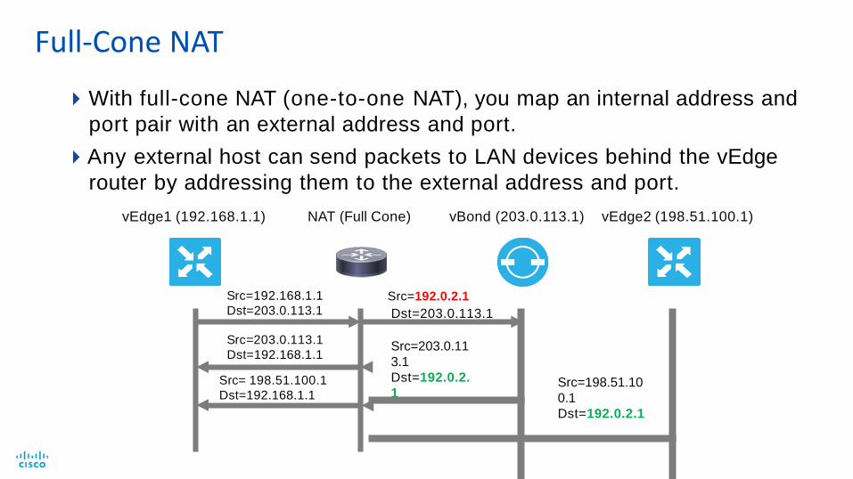
With full-cone NAT (one-to-one NAT), you map an internal address and
port pair with an external address and port.
Any external host can send packets to LAN devices behind the vEdge
router by addressing them to the external address and port.
vEdge1 (192.168.1.1) NAT (Full Cone) vBond (203.0.113.1) vEdge2 (198.51.100.1)
Src=192.168.1.1
Dst=203.0.113.1Src=192.0.2.1
Src=203.0.113.1
Dst=192.168.1.1
Src= 198.51.100.1
Dst=192.168.1.1
Dst=203.0.113.1
Src=203.0.11
3.1
Dst=192.0.2.
1Src=198.51.10
0.1
Dst=192.0.2.1
Full-Cone NAT

Address-Restricted Cone NAT
Src=192.168.1.1
Dst=203.0.113.1
Src=192.0.2.1
Dst=203.0.113.1
vEdge1 (192.168.1.1) NAT (Restricted Cone) vBond (203.0.113.1) vEdge2 (198.51.100.1)
Src=203.0.113.1
Dst=192.168.1.1Src=203.0.113.1
Dst=192.0.2.1
Src=198.51.100.1
Dst=192.0.2.1
XSrc=192.168.1.1
Dst=198.51.100.1Src=192.0.2.1
Dst=198.51.100.1
Src=198.51.100.1
Dst=192.0.2.1Src=198.51.100.1
Dst=192.168.1.1
Any external host can send a packet to an internal IP address if the
internal device initiates a connection to the external host by using the
previously created address mappings.

Similar to address-restricted cone NAT, with ports added to the mapping.
Src=192.168.1.1:12346
Dst=203.0.113.1:12346Src=192.0.2.1:5678,
Dst=203.0.113.1:12346
vEdge1 (192.168.1.1) vBond (203.0.113.1) vEdge2 (198.51.100.1)NAT (Port-Restricted Cone)
Src=203.0.113.1:12346
Dst=192.168.1.1:12346
Src=203.0.113.1:666
Dst=192.0.2.1:5678
XSrc=203.0.113.1:12346
Dst=192.0.2.1:5678
Port-Restricted Cone NAT

Symmetric NAT
Src=192.168.1.1:12346
Dst=203.0.113.1:12346Src=192.0.2.1:5678,
Dst=203.0.113.1:12346
vEdge1 (192.168.1.1) vBond (203.0.113.1) vEdge2 (198.51.100.1)NAT (Symmetric)
Src=203.0.113.1:12346
Dst=192.168.1.1:12346
Src=203.0.113.1:12346
Dst=192.0.2.1:5678
X
Src=192.168.1.1:12346
Dst=198.51.100.1:12346Src=192.0.2.1:9012,
Dst=198.51.100.1:12346
Src=198.51.100.1:12346
Dst=192.0.2.1:9012
Src=198.51.100.1:12346
Dst=192.168.1.1:12346
Src=198.51.100.1:12346
Dst=192.0.2.1:5678
Request from the same internal IP address and port to a specific destination IP address and port
is mapped to a unique external source IP address and port.
Only an external host that receives a packet from an internal host can send a packet back.

Site A Site B IPsec Tunnel Status
Public Public
Full Cone Full Cone
Full Cone Port-/Address-Restricted
Port-/Address-Restricted Port-/Address-Restricted
Public Symmetric
Full Cone Symmetric
Symmetric Port-/Address-Restricted
Symmetric Symmetric
Direct IPsec Tunnel No Direct IPsec Tunnel (traffic traverses hub) Mostly Encountered
NAT Traversal Combinations

Zero Touch Provisioning – WAN Edge Appliance
• The PnP Connection Manager
can redirect to cloud-hosted
or On-Prem controllers.
• New devices are linked to
organization using the Smart
Account when placing order.
• Additional devices can be
associated with the customer
using the PnP Connect portal
• No on-prem ZTP server
support for IOS-XE SDWAN
devices at the moment.
Controllers
Full Registration
and ConfigurationIOS-XE SD-WAN
3 4 5
Connection
Manager
1 2
Requirements: DHCP on WAN interface
DNS to resolve devicehelper.cisco.com

1. Provide Internet Access and DHCP Server with DNS.
2. Preprovision the router in vManage (upload the WAN Edge list).
3. Load SD-WAN image to the Cisco IOS XE router (bootflash).
4. Set the boot statement (boot system X).
5. Reboot the router.
6. Upon reboot, execute the following command:request platform software sdwan software reset
(The command completely removes all configuration plus files that are not
SD-WAN-related, admin shutdown interfaces, and reboots)
7. Upon bootup, plug-and-play process begins and the router is onboarded
like any other vEdge with the standard ZTP process.
Deploying cEdge Devices by Using Plug-and-Play

Standard ZTP Process
1. The router contacts PNP connect at devicehelper.cisco.com, presents its serial file and
gets SD-WAN related information (vBond IP, organization name, etc.).
2. The router contacts vBond over a secure tunnel; after authentication, vBond sends the
vManage IP to the router.
3. The router contacts vManage over secure tunnel; after authentication, vManage sends full
the configuration to the router.
4. The router contacts vSmart over a secure
tunnel; after authentication, the router joins the
SD-WAN fabric. 1
IOS XE Router
vSmartvManagevBondPNP-Connect
devicehelper.cisco.comStandard ZTP process
23
4
The router reaches out to vBond and performs standard SD-WAN zero-touch provisioning:

Each order requires a Smart Account and a virtual account.
If the customer does not assign the virtual account, Cisco IT creates the
virtual account and assigns it automatically.
One virtual account corresponds to an overlay.
Smart Account:
Company A
Virtual Account:
Customer 1
Virtual Account:
Customer 2
Virtual Account:
Customer 3
Smart Account and Virtual Account

Device Configuration Template Overview
Device template
System
VPN0
VPN i/f
VPN512
VPN i/f
Service VPNs
banner
….
VPN0 template
number/name
route
services
VPN Interface Ethernet
shut
interface name
IPv4 address
tunnel
color
VPN512 template
number/name
route
services
System template
site ID
system IP
overlay IDLevel 1: Device Template
Level 2: Feature Templates

Centralized feature templates
Configuration with variables
Self-recover on misconfiguration
WAN Edge
This device template applies to vEdge 100
B models and has 16 feature templates
associated with it.
Centralized Device Configuration Through Templates

Define device’s complete
operational configuration.
Device templates reference a
number of feature templates.
Device model-specific‒individual template for each device type.
No device templates are defined in
a new installation, by default.
Device Templates

Represent individual building blocks of the configuration
Device model–specific
Attached to
devices by
using device
templates
Feature Templates
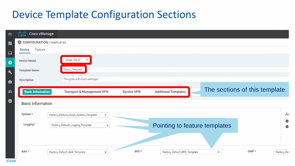
The sections of this template
templatesPointing to feature templates
Device Template Configuration Sections

You can customize every device
specific variable name.
The first feature
template in a device
template is the system
settings.
Here we rediscover
many parameters that
we previously
discussed, such as
System-IP and Site-ID.
Creating Device Template – System Settings

After you finalize the template and associate its feature templates, you must attach the
device template to devices–initially 0 devices are attached to the template.
In the template overview screen, click the More Options icon (…) on the right of a template,
and choose Attach Devices.
Applying the Device Template

Choose the devices and click Attach.
Attaching Devices to Device Templates
Only devices that match the
device type are displayed.

Defining Variables for Device Templates
To edit parameters of a single
device, click here.
For bulk edits of all parameters of all devices, download a CSV file here.

Defining Variables from through Manual Device Edit
Other parameters
are still required.
Some parameters were
configured already.
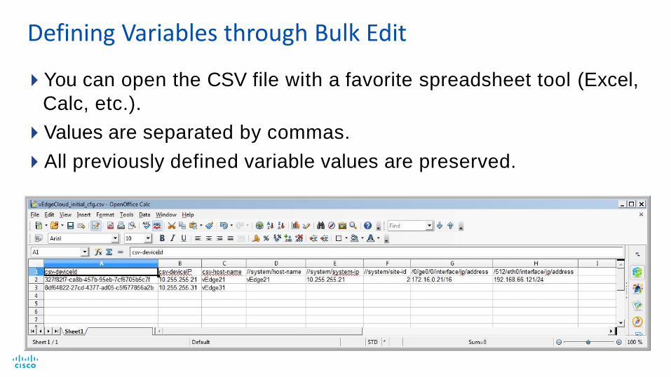
You can open the CSV file with a favorite spreadsheet tool (Excel,
Calc, etc.).
Values are separated by commas.
All previously defined variable values are preserved.
Defining Variables through Bulk Edit

Uploading the CSV
Use the upload
arrow icon to
upload the CSV file.

Device Provisioning
Modify default
Device Rollback
settings.
Click the individual
device to validate
the syntax.

Config Preview–displays the configuration to be pushed to the
device.
Config Diff–compares the new configuration with existing one.
Validating a Configuration Before Provisioning
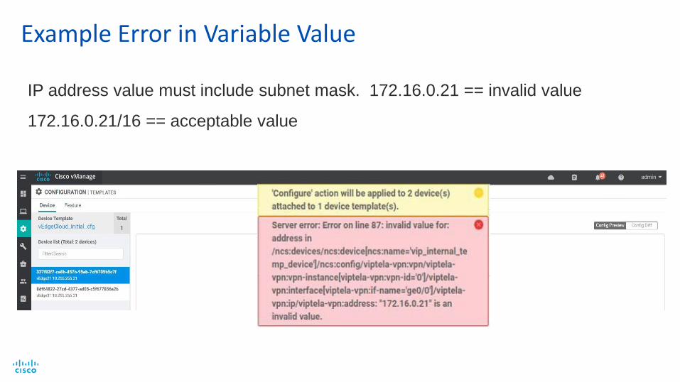
Example Error in Variable Value
IP address value must include subnet mask. 172.16.0.21 == invalid value
172.16.0.21/16 == acceptable value