
Cisco Remote-PHY Solution GuideCMC),whichconnectsthedigitalfiberandthe...
170
Cisco Remote-PHY Solution Guide First Published: August 01, 2014 Last Modified: July 02, 2015 Americas Headquarters Cisco Systems, Inc. 170 West Tasman Drive San Jose, CA 95134-1706 USA http://www.cisco.com Tel: 408 526-4000 800 553-NETS (6387) Fax: 408 527-0883
-
Upload
dangkhuong -
Category
Documents
-
view
236 -
download
2
Transcript of Cisco Remote-PHY Solution GuideCMC),whichconnectsthedigitalfiberandthe...

Cisco Remote-PHY Solution GuideFirst Published: August 01, 2014
Last Modified: July 02, 2015
Americas HeadquartersCisco Systems, Inc.170 West Tasman DriveSan Jose, CA 95134-1706USAhttp://www.cisco.comTel: 408 526-4000 800 553-NETS (6387)Fax: 408 527-0883

© 2015 Cisco Systems, Inc. All rights reserved.
C O N T E N T S
P r e f a c e Preface vii
Audience vii
Purpose vii
Document Conventions vii
Related Documentation ix
Obtaining Documentation and Submitting a Service Request x
Feature Information for the Cisco Remote-PHY Solution x
C H A P T E R 1 Cisco Remote-PHY Solution Overview 1
Introduction 1
Benefits 2
Architecture Overview 2
Cisco Cable Modem Termination System 3
Cisco Coaxial Media Converter 4
RF I/O Module 7
Motherboard Module 10
Power Supply Unit 12
FRx 13
Cisco uBR-MC3GX60V-RPHY Line Card 14
SFP Modules for the Cisco uBR-MC3GX60V-RPHY Line Card 17
Optical Line Terminal 18
Product Identifiers 19
License Information 24
How to Order 24
C H A P T E R 2 Cisco Remote-PHY Solution Deployment 25
Design Considerations 25
Cisco Remote-PHY Solution Guide iii

Network Architecture 26
Network Topologies 26
Network Cables 29
C H A P T E R 3 Installing the Cisco Remote-PHY Solution 31
Preparing for the Installation 31
General Safety Guidelines 31
Electrical Equipment Guidelines 32
Preventing Electrostatic Discharge Damage 32
Site Requirements 33
Environmental Requirements for the Cisco CMC 33
Environmental Requirements for the Cisco uBR-MC3GX60V-RPHY Line Card 34
Power Guidelines 35
Laser Safety Guidelines for the Cisco CMC 35
Mounting Considerations for the Cisco CMC 35
Wall-Mounting Guidelines for the Cisco CMC 36
Strand-Mounting Guidelines for the Cisco CMC 36
Tools for Installation 36
Tools for the Cisco CMC Installation 36
Tools for the Cisco uBR-MC3GX60V-RPHY Line Card Installation 37
Torque Specifications for the Cisco CMC 37
Unpacking the Equipment 38
Installing the Cisco CMC 38
Mounting the Cisco CMC 39
Wall-Mounting the Cisco CMC 39
Strand-Mounting the Cisco CMC 40
Opening the Cisco CMC 42
Removing and Installing the Accessories on the Cisco CMC 43
Installing the Coaxial Cables on the Cisco CMC 46
Trimming the Center Conductor on the F-Connector 46
Connecting the Coaxial Cable to the Cisco CMC 47
Installing a Fiber Adapter on the Cisco CMC 50
Installing an SFP Module on the Cisco CMC 52
Connecting the Optical Fibers to the SFP Module 53
Connecting the RJ-45 Cables to the Cisco CMC 55
Cisco Remote-PHY Solution Guideiv
Contents

Connecting the Optical Fibers to the FRx 58
Connecting I/O to the Cisco CMC 60
Enabling the 4-Way Forward Output RF Configuration on the Cisco CMC 60
Enabling the 2-Way Forward Output RF Configuration on the Cisco CMC 62
Enabling the 4-Way Reverse Input RF Configuration on the Cisco CMC 64
Enabling the 2-Way Reverse Input RF Configuration on the Cisco CMC 65
Powering Up the Cisco CMC 67
Grounding the Cisco CMC 67
Powering Up the Cisco CMC with the 220VAC PSU 69
Powering Up the Cisco CMC with the 60VAC PSU 70
Connecting 60VAC Power to the Cisco CMC Through the Power Port 70
Connecting 60VAC Power to the Cisco CMC Through the RF Port 72
Closing the Cisco CMC 74
Installing the Cisco uBR-MC3GX60V-RPHY Line Card 77
Removing an SFP Module from the Existing Line Card 77
Removing the Existing Line Card from the Card Slot 78
Installing the Cisco uBR-MC3GX60V-RPHY Line Card in the Card Slot 80
Installing an SFP Module on the Cisco uBR-MC3GX60V-RPHY Line Card 82
Connecting a Network Cable to an SFP Module 84
C H A P T E R 4 Configuring the Cisco Remote-PHY Solution 87
Prerequisites for Configuring the Cisco Remote-PHY Solution 87
Restrictions for Configuring the Cisco Remote-PHY Solution 87
How to Configure the Cisco Remote-PHY Solution 87
Configuring the Gigabit Ethernet Interface on the Cisco uBR-MC3GX60V-RPHY Line
Card 88
Configuring the Modular Cable Controller on the Cisco uBR-MC3GX60V-RPHY Line
Card 90
Configuring the Modular Cable Interface on the Cisco uBR-MC3GX60V-RPHY Line Card
93
Configuring the Wideband Cable Interface on the Cisco uBR-MC3GX60V-RPHY Line Card
94
Configuring the Cable Interface on the Cisco uBR-MC3GX60V-RPHY Line Card 95
Configuring a Channel Group on the Cisco uBR-MC3GX60V-RPHY Line Card 99
Configuring the Fiber Node on the Cisco uBR-MC3GX60V-RPHY Line Card 101
Cisco Remote-PHY Solution Guide v
Contents

Configuring the Layer 3 CIN Network support 102
Configuring the Downstream RF Power on the Cisco CMC 104
Configuring the FRx on the Cisco CMC 106
Configuration Example for the Cisco Remote-PHY Solution 106
Example: Configuring the Cisco Remote-PHY Solution 106
Example: Configuring CMTS and Router in Layer 3 CIN Network 111
C H A P T E R 5 Upgrading the Cisco Remote-PHY Solution 137
Upgrading the Cisco CMC Image through the Cisco CMTS 137
Upgrading the Cisco CMC Image through the Cisco CMC Console 139
C H A P T E R 6 Maintaining and Monitoring the Cisco Remote-PHY Solution 141
Monitoring the Cisco Remote-PHY Solution 141
Verifying the Cisco CMC Using the LEDs 141
Verifying the Cisco CMC Using the CLI 143
Verifying the Cisco uBR-MC3GX60V-RPHY Line Card Installation Using LEDs 144
Verifying the Cisco uBR-MC3GX60V-RPHY Line Card Using the CLI 145
Maintaining the Cisco Remote-PHY Solution 147
Using the Console Port on the Cisco CMC 147
Removing the Coaxial Cable from the Cisco CMC 150
Removing the Fiber Adapter from the Cisco CMC 153
Removing the SFP Module from the Cisco CMC 154
Online Insertion and Removal of the Cisco uBR-MC3GX60V-RPHY Line Card 155
C H A P T E R 7 Troubleshooting the Cisco Remote-PHY Solution 157
Troubleshooting the Cisco Remote-PHY Solution 158
Troubleshooting: Cisco uBR-MC3GX60V-RPHY Line Card Link LED Does Not
Illuminate 158
Troubleshooting: Cisco CMC Resets After DHCP Timeout 159
Troubleshooting: Cisco CMC is Not Working 159
Troubleshooting: The Cisco uBR-MC3GX60V-RPHY Line Card is Not Working 159
Troubleshooting: The DTI Timer is Not Working 160
Cisco Remote-PHY Solution Guidevi
Contents

Preface
• Audience, page vii
• Purpose, page vii
• Document Conventions, page vii
• Related Documentation, page ix
• Obtaining Documentation and Submitting a Service Request, page x
• Feature Information for the Cisco Remote-PHY Solution, page x
AudienceThis guide is intended for network or hardware technicians responsible for installing, connecting, andconfiguring the Cisco Remote-PHY solution and associated equipment at the cable head end or distributionhub. The network or hardware technicians should be familiar with the base operating parameters and serviceofferings of the cable plant where they intend to install this equipment.
Only trained and qualified personnel should be allowed to install, replace, or service this equipment.Statement 1030
Warning
PurposeThis document describes in detail the Cisco Coaxial Media Converter and the Cisco uBR-MC3GX60V-RPHYline card in the Cisco Remote-PHY solution.
This document does not provide detailed information on the other network components in theCisco Remote-PHY solution.
Document ConventionsThis document uses the following conventions:
Cisco Remote-PHY Solution Guide vii

DescriptionConvention
Both the ^ symbol and Ctrl represent the Control (Ctrl) key on a keyboard.For example, the key combination ^D or Ctrl-D means that you holddown the Control key while you press the D key. (Keys are indicated incapital letters but are not case sensitive.)
^ or Ctrl
Commands and keywords and user-entered text appear in bold font.bold font
Document titles, new or emphasized terms, and arguments for which yousupply values are in italic font.
Italic font
Terminal sessions and information the system displays appear in courierfont.
Courier font
Bold Courier font indicates text that the user must enter.Bold Courier font
Elements in square brackets are optional.[x]
An ellipsis (three consecutive nonbolded periods without spaces) aftera syntax element indicates that the element can be repeated.
...
A vertical line, called a pipe, indicates a choice within a set of keywordsor arguments.
|
Optional alternative keywords are grouped in brackets and separated byvertical bars.
[x | y]
Required alternative keywords are grouped in braces and separated byvertical bars.
{x | y}
Nested set of square brackets or braces indicate optional or requiredchoices within optional or required elements. Braces and a vertical barwithin square brackets indicate a required choice within an optionalelement.
[x {y | z}]
A nonquoted set of characters. Do not use quotation marks around thestring or the string will include the quotation marks.
string
Nonprinting characters such as passwords are in angle brackets.< >
Default responses to system prompts are in square brackets.[ ]
An exclamation point (!) or a pound sign (#) at the beginning of a lineof code indicates a comment line.
!, #
Reader Alert Conventions
This document uses the following conventions for reader alerts:
Cisco Remote-PHY Solution Guideviii
PrefaceDocument Conventions

Means reader take note. Notes contain helpful suggestions or references to material not covered in themanual.
Note
Means the following information will help you solve a problem.Tip
Means reader be careful. In this situation, you might do something that could result in equipment damageor loss of data.
Caution
Means the described action saves time. You can save time by performing the action described in theparagraph.
Timesaver
Means reader be warned. In this situation, you might perform an action that could result in bodilyinjury.
Warning
Related DocumentationIn addition to this document, the following documents and resources provide additional information relatedto the Cisco Remote-PHY solution.
Release Notes
• Release Notes for Cisco Coaxial Media Converter
• Cisco Remote-PHY Solution Release Notes for Cisco IOS Release 12.2(33)CX
Regulatory Compliance and Safety Information
• Regulatory Compliance and Safety Information for Cisco Coaxial Media Converter
• Regulatory Compliance and Safety Information for the Cisco uBR10012 Universal Broadband Router
Installation Guide
• Cisco uBR10012 Universal Broadband Router Hardware Installation Guide
Command Reference
• Cisco Coaxial Media Converter Command Reference
• Cisco CMTS Command Reference
Cisco Remote-PHY Solution Guide ix
PrefaceRelated Documentation

Configuration Guide
• Cisco IOS CMTS Cable Software Configuration Guide, Release 12.2SC
Licensing Information
• Software License Activation on Cisco CMTS Routers
MIB Information
• Cisco CMTS Universal Broadband Router Series MIB Specifications Guide
Obtaining Documentation and Submitting a Service RequestFor information on obtaining documentation, using the Cisco Bug Search Tool (BST), submitting a servicerequest, and gathering additional information, seeWhat's New in Cisco Product Documentation, at: http://www.cisco.com/c/en/us/td/docs/general/whatsnew/whatsnew.html.
Subscribe toWhat's New in Cisco Product Documentation, which lists all new and revised Cisco technicaldocumentation as an RSS feed and delivers content directly to your desktop using a reader application. TheRSS feeds are a free service.
Feature Information for the Cisco Remote-PHY SolutionUse Cisco Feature Navigator to find information about platform support and software image support.Cisco Feature Navigator enables you to determine which software images support a specific software release,feature set, or platform. To access Cisco Feature Navigator, go to http://tools.cisco.com/ITDIT/CFN/. Anaccount on http://www.cisco.com/ is not required.
The below table lists only the software release that introduced support for a given feature in a givensoftware release train. Unless noted otherwise, subsequent releases of that software release train alsosupport that feature.
Note
Table 1: Feature Information for the Cisco Remote-PHY Solution
Feature InformationReleaseFeature Name
TheCisco uBR-MC3GX60V-RPHYline card and Cisco CMC wereintroduced.
Cisco IOS Release 12.2(33)CXCisco Remote-PHY Solution
Cisco Remote-PHY Solution Guidex
PrefaceObtaining Documentation and Submitting a Service Request

C H A P T E R 1Cisco Remote-PHY Solution Overview
• Introduction, page 1
• Benefits, page 2
• Architecture Overview, page 2
• Cisco Cable Modem Termination System, page 3
• Cisco Coaxial Media Converter, page 4
• Cisco uBR-MC3GX60V-RPHY Line Card , page 14
• Optical Line Terminal, page 18
• Product Identifiers, page 19
• License Information, page 24
• How to Order, page 24
IntroductionDriven by market evolution towards triple-play services, cable operators in emerging markets are seekingstandardized and digital fiber-based solutions for economical and future proof access technologies. Much ofthe demand is driven by the need to provide higher bandwidth packet transport for Internet connectivity, videoand voice services.
Data Over Cable Systems Interface Standard (DOCSIS®) is a standardized technology for services over cableand thus has strong interoperability between system providers. It also provides robust Quality of Service (QoS)methods, ensuring packet delivery during periods of network congestion. Traditionally, DOCSIS runs onlinear fiber (or HFC) to provide service and is not naturally applicable for digital fiber. Cisco has bridged thegap by introducing a new access technology called the Remote-PHY.
Existing Architecture
In the emerging markets, most triple-play consumers live in multi-tenant buildings (referred to as MultiDwelling Units or MDU) with the number of residents usually being less than 500 residents per building orcluster. These buildings are typically served by fiber with one of several “final 100 meter” technologies installedin the buildings. These technologies include fiber, twisted pair, Ethernet, and coaxial. Cable operators have
Cisco Remote-PHY Solution Guide 1

access to the cable in the building and use this cable for their services. Several technologies exist for enablingtwo-way services over cable. These include a number of proprietary and vendor-specific methods. However,a standards-based approach to using cable is typically preferred by operators, since this ensures vendorinteroperability.
Need for the Cisco Remote-PHY Solution
DOCSIS and EuroDOCSIS are standards that define two-way operation over a cable network. DOCSISprovides the necessary Quality of Service (QoS) tools for ensuring voice call connectivity during periods ofnetwork congestion that are anticipated in triple-play networks. DOCSIS is a robust and mature technologyfor voice, video, and IP video services.
The Cisco Remote-PHY solution leverages existing IP technologies like Ethernet PON (EPON), Gigabit-capablePassive Optical Networks (GPON), and Metro Ethernet (MetroE) equipment; it deploys DOCSIS in MDUsover digital fiber to enable two-way services over cable.
BenefitsThe Cisco Remote-PHY solution provides a cost-effective digital fiber-based DOCSIS solution that usesEthernet PON (EPON), Gigabit-capable Passive Optical Networks (GPON), or Metro Ethernet (MetroE) asthe transmission network between the Cisco CMTS and CM. Both the PON technology and DOCSIS is usedin the same network.
• Simple and low cost PON transmission as opposed to costly HFC transformation.
• Reduced investment cost including capital and operational expenditure.
• Low-cost yet highly stable Cisco CMC (includes only the PHY layer).
• Reduced CMTS hardware complexity.
• No restriction on Converged Interconnect Network (CIN) network.
• Futureproof architecture. Easy to migrate as the hardware and control functions are on separate layers.
• End-to-end QoS assurance provided by DOCSIS.
• Support for all DOCSIS services.
• Support for existing DOCSIS network provisioning system.
• High access bandwidth.
•With deep fiber, the optical noise contribution to SNR is eliminated. As a result, the remote QAMmodulator runs at higher orders of modulation as compared to a centralized QAM modulator.
Architecture OverviewModular Headend Architecture version 2 (MHAv2) is a set of specifications for the Cisco Remote-PHYsolution. It uses digital fiber compatible baseband networking technology, such as Ethernet, EPON, or GPONto drive the fiber portion of the HFC plant. The coaxial portion of the plant remains the same. In MHAv2, theupstream PHY is located on the remote side and acts as the remote PHY system together with the downstreamPHY. This is a device called the Coaxial Media Converter (CMC), which connects the digital fiber and thecoaxial portions of the plant together. The CMC resides near or in buildings and has both RFI and Gigabit
Cisco Remote-PHY Solution Guide2
Cisco Remote-PHY Solution OverviewBenefits
Ethernet interfaces. The CMC provides layer 1 PHY (downstream and upstream PHY) functionality, layer 2MAC functionality, and layer 3 tunneling and forwarding support. The CMTS remains unchanged with theexception of the upstreamPHYbeingmoved to the remote CMC. The Cisco uBR-MC3GX60V-RPHY line cardinstalled in the Cisco CMTS does not have the RFI interfaces for downstream and upstream, instead, it hasGigabit Ethernet interfaces for both downstream and upstream.
Protocols that form this architecture include:
• Downstream External PHY Interface Decapsulation—Downstream External PHY Interface (DEPI) isa L2TPv3-based protocol defined for downstream DOCSIS MAC management and data packetsdecapsulation. It is unidirectional, that is, from CMTS to CMC.
DEPI supports:
• IP/User Datagram Protocol (UDP)
• DOCSIS MPT Mode (D-MPT)/Packet Streaming Protocol (PSP)
• Upstream External PHY Interface Encapsulation—Upstream External PHY Interface (UEPI) is aL2TPv3-based protocol defined for upstreamDOCSISMACmanagement and data packets encapsulation.It is unidirectional, that is, from CMC to CMTS.
UEPI:
• Does not support UDP
• Supports PSP mode only
• Supports multiple pseudowires for RNG/BW-REQ/SPECTRUM-MGMT/MAP
• GCP—Generic Control Protocol, sets up a control plane tunnel over a generic transport protocol suchas TCP or UDP. GCP is used to program CMC upstream PHY parameters from the CMTS. It is alsoused to control the CMC.
GCP supports:
• TCP/UDP
• DS/US PHY configuration and CMC provisioning/configuration
• Register mode and type, length, value (TLV) mode
• Notification
Cisco Cable Modem Termination SystemThe Cisco uBR10012 universal broadband router acts as the Cable Modem Termination System (CMTS) corefor the Cisco Remote-PHY architecture.
Following are its functions:
• Assigns downstream and upstream channels of the Cisco uBR-MC3GX60V-RPHY line card to theCisco CMC.
• Performs MAC classification, forwarding, and management functions.
• Handles the Cisco CMC configuration and management.
Cisco Remote-PHY Solution Guide 3
Cisco Remote-PHY Solution OverviewCisco Cable Modem Termination System

For more information on the Cisco CMTS, see the following documents:
• Cisco uBR10012 Universal Broadband Router Hardware Installation Guide
• Cisco IOS CMTS Cable Software Configuration Guide, Release 12.2SC
Cisco Coaxial Media ConverterThe Cisco Coaxial Media Converter (CMC) acts as the edge QAM in the Cisco Remote-PHY architecture. Itis located between the Cisco CMTS and the cable modem, and controlled by the Cisco CMTS. The Cisco CMChas network interfaces on one side connecting to the fiber (digital and linear) portion of the Hybrid FiberCoaxial (HFC) plant, and RF interfaces on the other side connecting to the coaxial portion of the HFC plant.The Cisco CMC can bemounted either on a wall or strand (aerial installation). The RF output of the Cisco CMCcan be combined with other services, such as, analog or digital video services. The Cisco CMC uses the linuxoperating system. Most of the Cisco CMC configurations are performed on the Cisco CMTS.
The Cisco CMC terminates the Ethernet Passive Optical Network (EPON) protocol with an embedded OpticalNetwork Unit (ONU) and originates the DOCSIS protocol using the DOCSISMAC and PHY layer technologyused in the Cisco CMTS. The Cisco CMC has built-in downstream PHY and upstream PHY, and a smallFPGA for DEPI decapsulation and UEPI encapsulation. The Cisco CMC supports up to 16 downstreamQAMchannels and four upstream channels.
For more information on the Cisco CMC product identifiers (PIDs), see Product Identifiers, on page 19.
The Cisco CMC has a hinged lid to allow access to the internal electrical and optical components. It also hasa waterproof rubber on the base and an EMI gasket on the lid to seal the equipment. The table below lists thedimensions of the Cisco CMC
Table 2: Physical Specifications of the Cisco CMC
ValueUnit
12.48 in (31.7 cm)Depth
15.86 in (40.3 cm)Width
6.69 in (17 cm)Height
26 lbs (11.8 kg)Weight
Cisco Remote-PHY Solution Guide4
Cisco Remote-PHY Solution OverviewCisco Coaxial Media Converter
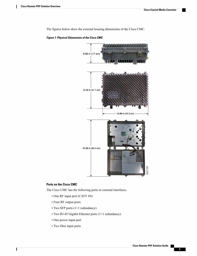
The figures below show the external housing dimensions of the Cisco CMC.
Figure 1: Physical Dimensions of the Cisco CMC
Ports on the Cisco CMC
The Cisco CMC has the following ports or external interfaces:
• One RF input port (CATV IN)
• Four RF output ports
• Two SFP ports (1+1 redundancy)
• Two RJ-45 Gigabit Ethernet ports (1+1 redundancy)
• One power input port
• Two fiber input ports
Cisco Remote-PHY Solution Guide 5
Cisco Remote-PHY Solution OverviewCisco Coaxial Media Converter

• One console port
The figure below shows the ports on the external housing of the Cisco CMC.
Figure 2: Cisco CMC (closed)
RJ-45 port4CATV input (RF input port)1
RF output ports5Power port2
—Fiber input ports3
The figure below shows the ports that are located inside the Cisco CMC.
Figure 3: Cisco CMC (open)
Cisco Remote-PHY Solution Guide6
Cisco Remote-PHY Solution OverviewCisco Coaxial Media Converter

SFP ports3RJ-45 Gigabit Ethernet ports1
—Console port2
The Cisco CMC contains the following modules:
RF I/O ModuleThe RF I/O module on the Cisco CMC can split the CATV input or one downstream into four RF outputs onthe downstream. The RF I/O module can also combine four RF outputs into one upstream. The figure belowshows the RF I/O module on the Cisco CMC.
Figure 4: RF I/O Module on the Cisco CMC
Reverse output attenuator pads7Forward equalizers1
Forward pads8Reverse test point2
Downstream RF input port9Reverse input attenuator pad3
Upstream RF output port10Forward test point4
RF input (CATV IN) port11Signal directors5
Base cover12RF output ports6
Cisco Remote-PHY Solution Guide 7
Cisco Remote-PHY Solution OverviewRF I/O Module

The RF I/O module consists of the following components. Some of the components on the Cisco CMC(attenuator pads, equalizers, and signal directors) can be removed and replaced with the same components ofdifferent values during the setup procedures.
Table 3: Components of the RF I/O Module
DescriptionComponent
The Cisco CMC has one RF input port, which provides the CATV input froman external node or amplifier.
RF input port
The Cisco CMC has four RF output ports, which are used for forward signaloutput and reverse signal input.
RF output ports
The Cisco CMC has three test points, which are used for monitoring the signals.It consists of the following types of test points:
• Reverse test point—The Cisco CMC has one reverse test point, which isused for monitoring the reverse signal.
• Forward test point—The Cisco CMC has two forward test points, whichare used for monitoring the forward signal.
Test points
The Cisco CMC has one downstream RF input port from the motherboardmodule.
DownstreamRF input port
The Cisco CMC has one upstream RF output port to the motherboard module.Upstream RF output port
The Cisco CMC has two forward equalizers.Equalizers
A signal director routes or splits the RF input signal to the RF output ports. TheCisco CMC has two signal directors.
The Cisco CMC supports the following components as a signal director:
• Splitter
• Jumper
Signal directors
The Cisco CMC has the following attenuator pads:
• Two forward attenuator pads
• One reverse input attenuator pad
• Two reverse output attenuator pads
Attenuator pads
Cisco Remote-PHY Solution Guide8
Cisco Remote-PHY Solution OverviewRF I/O Module

Block Diagram
The figure below shows the block diagram of the Cisco CMC RF I/O module:
Figure 5: Block Diagram of the Cisco CMC RF I/O Module
Cisco Remote-PHY Solution Guide 9
Cisco Remote-PHY Solution OverviewRF I/O Module

Motherboard ModuleThe figure below shows the motherboard module of the Cisco CMC:
Figure 6: Motherboard Module of the Cisco CMC
Upstream RF input port6RJ-45 Gigabit Ethernet ports1
Power connector7SFP ports2
FRx and RF I/O connector8Reset button3
Console port and golden image jumper9LEDs4
—Downstream RF output port5
Cisco Remote-PHY Solution Guide10
Cisco Remote-PHY Solution OverviewMotherboard Module

The Cisco CMC motherboard module consists of the following components:
Table 4: Components of the Motherboard Module
DescriptionComponent
TheCisco CMChas twoRJ-45Gigabit Ethernet ports, which are used to connectit to the switch or OLT. The Cisco CMC supports 1+1 redundancy for the RJ-45Gigabit Ethernet ports.
RJ-45 ports
The Cisco CMC has two SFP ports, which are used to connect it to the switchor OLT. The Cisco CMC supports 1+1 redundancy for the SFP ports. TheCisco CMC supports Gigabit Ethernet SFP and EPON SFP.
SFP ports
The Cisco CMC has a reset button, which is used to power-cycle themotherboard module (that is, power it down and then power it up).
Reset button
The Cisco CMC has the following LEDs on the motherboard module formonitoring the Cisco CMC:
• PWR—Power LED
• UPLINK—Uplink LED
• DS RF—Downstream RF LED
• ALARM—Alarm LED
• STATUS—Status LED
• RESERVED—Reserved LED
• GE0 and GE1—RJ-45 Gigabit Ethernet LEDs
LEDs
The Cisco CMC has one console port, which is used to connect it to a PC. Thisport has three pins. You must use a 3-pin connector to connect to this port.
Console port
The golden image jumper has three pins, two ground-pins and one goldenimage-pin. When the golden image-pin is shorted with the ground-pin, theCisco CMC boots with the golden image.
Golden image jumper
The Cisco CMC has an 8-pin 12 V power connector, which provides power tothe motherboard module.
Power connector
The Cisco CMC has one FRx and RF I/O connector, which provides theUniversal Asynchronous Receiver and Transmitter (UART) signals to the FRx.
FRx and RF I/O connector
The Cisco CMC has one downstream RF output port, which is connected tothe downstream RF input port on the RF I/O module through a connector.
DownstreamRF output port
The Cisco CMC has one upstream RF input port, which is connected to theupstream RF output port on the RF I/O module through a connector.
Upstream RF input port
Cisco Remote-PHY Solution Guide 11
Cisco Remote-PHY Solution OverviewMotherboard Module
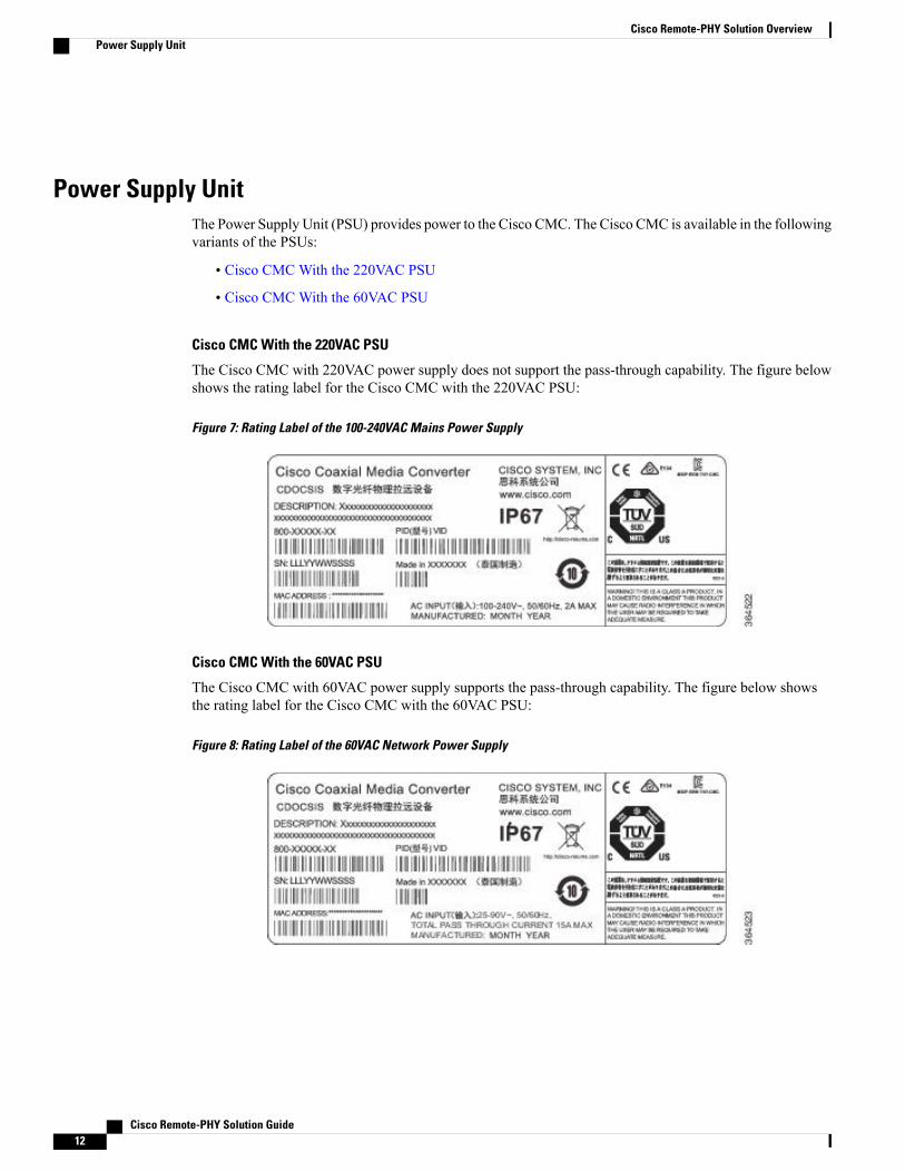
Power Supply UnitThe Power Supply Unit (PSU) provides power to the Cisco CMC. The Cisco CMC is available in the followingvariants of the PSUs:
• Cisco CMC With the 220VAC PSU
• Cisco CMC With the 60VAC PSU
Cisco CMC With the 220VAC PSU
The Cisco CMC with 220VAC power supply does not support the pass-through capability. The figure belowshows the rating label for the Cisco CMC with the 220VAC PSU:
Figure 7: Rating Label of the 100-240VAC Mains Power Supply
Cisco CMC With the 60VAC PSU
The Cisco CMC with 60VAC power supply supports the pass-through capability. The figure below showsthe rating label for the Cisco CMC with the 60VAC PSU:
Figure 8: Rating Label of the 60VAC Network Power Supply
Cisco Remote-PHY Solution Guide12
Cisco Remote-PHY Solution OverviewPower Supply Unit
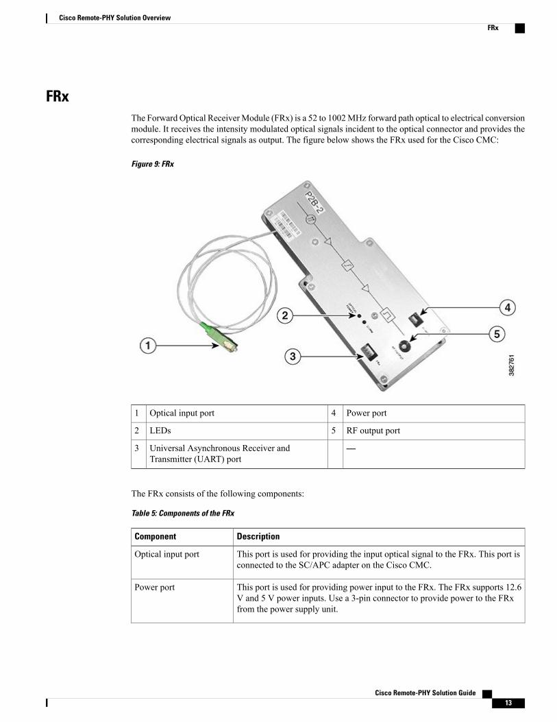
FRxThe Forward Optical ReceiverModule (FRx) is a 52 to 1002MHz forward path optical to electrical conversionmodule. It receives the intensity modulated optical signals incident to the optical connector and provides thecorresponding electrical signals as output. The figure below shows the FRx used for the Cisco CMC:
Figure 9: FRx
Power port4Optical input port1
RF output port5LEDs2
—Universal Asynchronous Receiver andTransmitter (UART) port
3
The FRx consists of the following components:
Table 5: Components of the FRx
DescriptionComponent
This port is used for providing the input optical signal to the FRx. This port isconnected to the SC/APC adapter on the Cisco CMC.
Optical input port
This port is used for providing power input to the FRx. The FRx supports 12.6V and 5 V power inputs. Use a 3-pin connector to provide power to the FRxfrom the power supply unit.
Power port
Cisco Remote-PHY Solution Guide 13
Cisco Remote-PHY Solution OverviewFRx

DescriptionComponent
LEDs are used for monitoring if the optical input level and communication areoperational on the FRx. The FRx contains two LEDs:
• OPTICAL POWER—Optical input power LED
• COMM—Communication status LED
LEDs
This port is used for providing the RF output signal to the Cisco CMC.RF output port
This port is used for connecting the control cable from the Cisco CMC to theFRx. Use a 4-pin connector for the UART port.
UART port
Cisco uBR-MC3GX60V-RPHY Line CardThe Cisco uBR-MC3GX60V-RPHY line card transmits and receives RF signals between the subscriber andheadend over the hybrid fiber-coaxial (HFC) system and is DOCSIS 3.0-compliant. TheCisco uBR-MC3GX60V-RPHY line card is designed specifically for the Cisco uBR10012 router and conformsto the Modular CMTS (M-CMTS) architecture.
The Cisco uBR-MC3GX60V-RPHY line card is installed in the CMTS and connected to the Cisco CMC viathe EPON,GPON, orMetro Ethernet. The Cisco uBR-MC3GX60V-RPHY line card supports both downstreamand upstream traffic. The Cisco uBR-MC3GX60V-RPHY line card has three pairs of Gigabit Ethernet (GE)ports as external interfaces and 1 + 1 redundancy for the Metro Ethernet ports. Both the downstream andupstream traffic share the same ports.
The Cisco uBR-MC3GX60V-RPHY line card supports 24 downstream RF channels and 20 upstream RFchannels per Gigabit Ethernet port. Hence, a total of 72 downstreamRF channels and 60 upstreamRF channelsacross the Gigabit Ethernet ports.
Table 6: Physical Specifications of the Cisco uBR-MC3GX60V-RPHY Line Card
DimensionsUnit
21.65 in (55 cm )Width
14.17 in (3.6 cm)Height
172.44 in (43.8 cm)Depth
12.99 lbs (5.895 kg)Weight
Cisco Remote-PHY Solution Guide14
Cisco Remote-PHY Solution OverviewCisco uBR-MC3GX60V-RPHY Line Card

Figure 10: Cisco uBR-MC3GX60V-RPHY Line Card
Front panel display (FPD)2Captive Screw1
Cisco uBR-MC3GX60V-RPHY line card contains the following components:
• LEDs—The LEDs are located on the front panel of the line card and indicates the status of the line card.
The line card has the following LEDs for monitoring its status:
◦POWER—Power LED
◦STATUS—Status LED
◦MAINT—Maintenance LED
◦GE0 through GE5—Gigabit Ethernet port LED
◦LK/ACT0 through LK/ACT5—Link LED for the Gigabit Ethernet port
• Gigabit Ethernet ports—The Cisco uBR-MC3GX60V-RPHY line card has three pairs of Gigabit Ethernetports as external interfaces and the SFP modules are inserted into the Gigabit Ethernet ports to connectto a switch or an OLT. For more information on SFP modules, see SFP Modules for theCisco uBR-MC3GX60V-RPHY Line Card, on page 17.
• Front panel display—The Front panel four-character alphanumeric display shows the licensing statusinformation of the US and DS channels.
Software License for the Cisco uBR-MC3GX60V-RPHY Line Card
The Cisco uBR-MC3GX60V-RPHY line card requires software licensing to restrict the number of US andDS channels used. The Cisco uBR-MC3GX60V-RPHY line card supports 16 to 60 US channels and 16 to 72DS channels.
Cisco Remote-PHY Solution Guide 15
Cisco Remote-PHY Solution OverviewCisco uBR-MC3GX60V-RPHY Line Card

The Cisco uBR-MC3GX60V-RPHY line card uses a smart chip authentication device to prevent counterfeitline cards. A digital signature is embedded in the line card, and the Public Key Encryption techniques areused to verify the authenticity of the digital signature. The software licenses are physically stored on the linecards. You cannot transfer the software licenses between different types of line cards.
The front panel four-character alphanumeric display on the line card shows the licensing status informationof the US and DS channels. The first two characters of the display represent the DS license count and the lasttwo characters represent the US license count.
The table below shows some of the US and DS channel combinations supported on theCisco uBR-MC3GX60V-RPHY line card and their corresponding license type.
Table 7: Software License for the Cisco uBR-MC3GX60V-RPHY Line Card
UpstreamDownstreamFront Panel Display
60723G60
40482G40
20241G20
14333314
Compatibility Matrix for the Cisco uBR-MC3GX60V-RPHY Line Card
Table 8: Software and Hardware Compatibility Matrix for the Cisco uBR-MC3GX60V-RPHY Line Card
Cisco IOS ReleaseProcessor EngineCisco CMTS Platform
12.2(33)CX and later releasesPRE4Cisco uBR10012 router
12.2(33)CX and later releasesPRE5Cisco uBR10012 router
Onboard Failure Logging
The Onboard Failure Logging (OBFL) feature enables the storage and collection of critical failure informationin the nonvolatile memory of a Field Replaceable Unit (FRU), like a route processor (RP) or line card. TheCisco uBR10000 series universal broadband router supports OBFL on PRE4, the Cisco SIP-600 jacket card,Cisco uBR-MC3GX60V-RPHY, Cisco uBR-MC3GX60V, Cisco UBR-MC20X20V, and the CiscouBR-MC5X20H line cards.
The data stored through OBFL assists in understanding and debugging the field failures upon Return MaterialAuthorization (RMA) of a RP or line card at repair and failure analysis sites. OBFL records operatingtemperatures, voltages, hardware uptime, and any other important events that assist board diagnosis in caseof hardware failures.
For more information about the feature, see Onboard Failure Logging.
Cisco Remote-PHY Solution Guide16
Cisco Remote-PHY Solution OverviewCisco uBR-MC3GX60V-RPHY Line Card

The sample output provided in the Onboard Failure Logging guide may vary slightly for the Cisco CMTSrouters.
Note
SFP Modules for the Cisco uBR-MC3GX60V-RPHY Line CardThe Small Form-factor Pluggable (SFP) modules are I/O devices that are inserted into the Gigbit Ethernetports, linking the ports to an OLT or a switch through a network cable.
The table below lists the SFP modules that are supported on the Cisco uBR-MC3GX60V-RPHY line card.The only restriction is that each SFP module must match the wavelength specifications on the other end ofthe cable and the cable must meet the stipulated cable length range for reliable communications.
Table 9: SFP Modules supported on the Cisco uBR-MC3GX60V-RPHY Line Card
Supported Cable TypeSupported ConnectorDescriptionSFP ModuleSFP PartNumber
CopperRJ-45 connectorProvides full-duplexGigbit Ethernetconnectivity tohigh-endworkstations, andbetween wiringclosets over anexisting coppernetworkinfrastructure.
RJ-45 copper(1000BASE-T)
SFP-GE-T
Multimode fiber(MMF)1
LC Fiber-Opticconnector
Contains a Class 1laser of 850 nm for1000BASE-SX(short-wavelength)applications.
Short wavelength(1000BASE-SX)
GLC-SX-MMD
Single-mode fiber(SMF)
Multimode fiber(MMF)
LC Fiber-Opticconnector
Contains a Class 1laser of 1310 nm for1000BASE-LX/LH(long-wavelength)applications.
Longwavelength/longhaul(1000BASE-LX/LH)
GLC-LH-SMD
Single-mode fiber(SMF)
LC Fiber-Opticconnector
Contains a Class 1laser of 1550 nm for1000BASE-ZX(extended-wavelength)applications.
Extendeddistance(1000BASE-ZX)
GLC-ZX-SMD2
1 A mode-conditioning patch cord is required at all times as per IEEE specifications.
Cisco Remote-PHY Solution Guide 17
Cisco Remote-PHY Solution OverviewSFP Modules for the Cisco uBR-MC3GX60V-RPHY Line Card

2 For the GLC-ZX-SM, the minimum attenuation between the transmit bore (TX) and the receive bore (RX) is 8 dB.When using shorter distances of single-modefiber cable, you might need to insert an inline optical attenuator in the link to avoid overloading the receiver.
The SFP modules can have three types of latches to secure it in a port socket. Determine the type of latch yourSFP module uses before you complete the installation and removal procedures.
Table 10: Supported SFP Latch Types
IllustrationDescriptionSFP Module
The bale clasp SFP module has aclasp that you use to remove or installthe SFP module in a Gigbit Ethernetport.
Bale clasp SFPmodule
The mylar tab SFP module has a tabthat you pull to remove the modulefrom a Gigbit Ethernet port.
Mylar tab SFP module
The actuator button SFP moduleincludes a button that you push toremove the SFP module from aGigbit Ethernet port.
Actuator button SFPmodule
For more information on SFPmodules, see Cisco Small Form-Factor PluggableModules for Gigabit EthernetApplications Data Sheet.
Optical Line TerminalOptical Line Terminal (OLT) equipment supports:
• Packet classification
• Switching functions that tag packets with their order of priority and the port on the CMC that mustreceive the packet
Cisco Remote-PHY Solution Guide18
Cisco Remote-PHY Solution OverviewOptical Line Terminal

Product IdentifiersThe tables below list the component product identifiers (PID) for the Cisco CMC and theCisco uBR-MC3GX60V-RPHY line card.
Table 11: Cisco CMC Component PIDs
PIDComponent
Cisco CMC
CMC-L-L-16X4Cisco CMC, 60V, 6 downstream (DS) and 4 upstream (US) channels, 42/54MHz
CMC-L-M-16x4Cisco CMC, 60 V, 16 DS and 4 US channels, 65/87MHz
CMC-L-L-16X4-NCisco CMC, 60 V, 16 DS and 4 US channels, 42/54MHz, with node
CMC-L-M-16x4-NCisco CMC, 60 V,16 DS and 4 US channels, 65/87MHz, with node
CMC-M-L-16X4-USCisco CMC, 110/220 V, 16 DS and 4 US channels, 42/54 MHz, US power cord
CMC-M-L-16X4-JPCisco CMC, 110/220 V, 16 DS and 4 US channels, 42/54 MHz, JP power cord
CMC-M-L-16X4-EUCisco CMC, 110/220 V, 16 DS and 4 US channels, 42/54 MHz, EU power cord
CMC-M-L-16X4-UKCisco CMC, 110/220 V, 16 DS and 4 US channels, 42/54 MHz, UK power cord
CMC-M-L-16X4-IDCisco CMC, 110/220 V, 16 DS and 4 US channels, 42/54 MHz, India powercord
CMC-M-M-16x4-CHCisco CMC, 110/220 V, 16 DS and 4 US channels, 65/87 MHz, CH power cord
CMC-M-M-16x4-JPCisco CMC, 110/220 V, 16 DS and 4 US channels, 65/87 MHz, JP power cord
CMC-M-M-16x4-USCisco CMC, 110/220 V, 16 DS and 4 US channels, 65/87 MHz, US power cord
CMC-M-M-16x4-EUCisco CMC, 110/220 V, 16 DS and 4 US channels, 65/87 MHz, EU power cord
CMC-M-M-16x4-UKCisco CMC, 110/220 V, 16 DS and 4 US channels, 65/87 MHz, UK power cord
CMC-M-M-16x4-AUCisco CMC, 110/220 V, 16 DS and 4 US channels, 65/87 MHz, AU power cord
CMC-M-L-16X4-USNCisco CMC, 110/220 V, 16 DS and 4 US channels, 42/54 MHz, US power cord,with node
CMC-M-L-16X4-EUNCisco CMC, 110/220 V, 16 DS and 4 US channels, 42/54 MHz, EU power cord,with node
Cisco Remote-PHY Solution Guide 19
Cisco Remote-PHY Solution OverviewProduct Identifiers

PIDComponent
CMC-M-L-16X4-JPNCisco CMC, 110/220 V, 16 DS and 4 US channels, 42/54 MHz, JP power cord,with node
CMC-M-L-16X4-UKNCisco CMC, 110/220 V, 16 DS and 4 US channels, 42/54 MHz, UK power cord,with node
CMC-M-L-16X4-IDNCisco CMC, 110/220 V, 16 DS and 4 US channels, 42/54 MHz, ID power cord,with node
CMC-M-M-16x4-CHNCisco CMC, 110/220 V, 16 DS and 4 US channels, 65/87 MHz, CH power cord,with node
CMC-M-M-16x4-JPNCisco CMC, 110/220 V, 16 DS and 4 US channels, 65/87 MHz, JP power cord,with node
CMC-M-M-16x4-USNCisco CMC, 110/220 V,16 DS 4 US channels, 65/87 MHz, US power cord, withnode
CMC-M-M-16x4-EUNCisco CMC, 110/220 V, 16 DS and 4 US channels, 65/87 MHz, EU power cord,with node
CMC-M-M-16x4-UKNCisco CMC, 110/220 V, 16 DS and 4 US channels, 65/87 MHz, UK power cord,with node
CMC-M-M-16x4-AUNCisco CMC, 110/220 V, 16 DS and 4 US channels, 65/87 MHz, AU power cord,with node
CMC-M-M-16x4-IDNCisco CMC, 110/220 V, 16 DS and 4 US channels, 65/87 MHz, ID power cord,with node
Gigabit Ethernet SFP
GLC-BX-U1000BASE-BX10 10KM distance
GLC-SX-MM-RGD1000BASE-SX 550M distance; rugged SFP
GLC-LX-SM-RGD1000BASE-LX/LH 10KM distance; rugged SFP
GLC-EX-SMD1000BASE-EX long-wavelength; with DOM
GLC-ZX-SM-RGD1000BASE-ZX 80KM distance; rugged SFP
Ethernet Passive Optical Network (EPON) SFP Optical Network Unit (ONU)
SFP-EPON-ONU-GE=EPON ONU, SFP type, Gigabit Ethernet throughput; industrial grade
FRx
Cisco Remote-PHY Solution Guide20
Cisco Remote-PHY Solution OverviewProduct Identifiers

PIDComponent
FRX-1G-RF50-T9=Optical Forward Receiver, 1 GHz, 50 dBmV, 9 dB tilt, with SC/APC, withAutomatic Gain Control (AGC), spare
RJ-45 Waterproof Glands
GLND-PG16-RJ-1HPG16 gland for RJ-45 with one hole
GLND-PG16-RJ-2HPG16 gland for RJ-45 with two holes
Port Plug
PLUG-CMC-RF=Port plug with O-Ring, 5/8" brass nickel plate
RF Connectors
FCONTOR-CMC-RF-M=Assembly 5/8" F-connector, metric
FCONTOR-CMC-RF-S=Assembly 5/8" F-connector, standard
AC Shunt
JUMPER-CMC=Plastic jumper, 0.8''C for the Cisco Remote-PHY solution
Console Cable
CAB-CONSOLE-DB9=Cisco CMC console cable, converter between DB9 and PCB
Fiber Adapters
OPT-ADP-SC-SC=Optical fiber adapter for SC/APC to SC/APC
OPT-ADP-SC-FC=Optical fiber adapter for SC/APC to FC/APC
1 GHz Attenuator Pads
5896930 dB
5896940.5 dB
5896951.0 dB
5896961.5 dB
5896972.0 dB
5896982.5 dB
5896993.0 dB
Cisco Remote-PHY Solution Guide 21
Cisco Remote-PHY Solution OverviewProduct Identifiers

PIDComponent
5897003.5 dB
5897014.0 dB
5897024.5 dB
5897035.0 dB
5897045.5 dB
5897056.0 dB
5897066.5 dB
5897077.0 dB
5897087.5 dB
5897098.0 dB
5897108.5 dB
5897119.0 dB
5897129.5 dB
58971310.0 dB
58971410.5 dB
58971511.0 dB
58971611.5 dB
58971712.0 dB
58971812.5 dB
58971913.0 dB
58972013.5 dB
1 GHz Forward Linear Equalizers
40072280 dB
40087781.5 dB
Cisco Remote-PHY Solution Guide22
Cisco Remote-PHY Solution OverviewProduct Identifiers

PIDComponent
40087793.0 dB
40087804.5 dB
40087816.0d B
40087827.5 dB
40087839.0 dB
400878410.5 dB
400878512.0 dB
400878613.5 dB
400878715.0 dB
400925816.5 dB
400925918.0 dB
400926019.5 dB
400926121.0 dB
Jumper
4011907Signal director jumper
Table 12: Cisco uBR-MC3GX60V-RPHY Line Card Component PIDs
Part NumberComponent
UBR-MC3GX60V-RPHYCisco uBR-MC3GX60V-RPHYLine Card for uBR10K supporting remote PHY;Base HW
UBR-MC3GX60V-RPHY=Spare Cisco uBR-MC3GX60V-RPHYLine Card for uBR10K supporting remotePHY; Base HW
UBR-MC3GX60V-R-SP=Spare 3G60V-RPHY w/ 0x0 License
UBR10-MC-COVER=Blank card slot cover
Small Form-Factor Pluggable (SFP)
SFP-GE-T, Cisco SystemsCisco 1000BASE-T
Cisco Remote-PHY Solution Guide 23
Cisco Remote-PHY Solution OverviewProduct Identifiers
Part NumberComponent
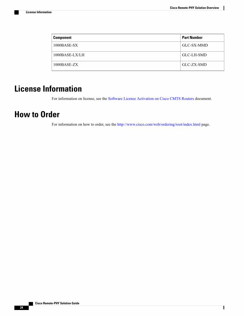
GLC-SX-MMD1000BASE-SX
GLC-LH-SMD1000BASE-LX/LH
GLC-ZX-SMD1000BASE-ZX
License InformationFor information on license, see the Software License Activation on Cisco CMTS Routers document.
How to OrderFor information on how to order, see the http://www.cisco.com/web/ordering/root/index.html page.
Cisco Remote-PHY Solution Guide24
Cisco Remote-PHY Solution OverviewLicense Information

C H A P T E R 2Cisco Remote-PHY Solution Deployment
• Design Considerations, page 25
• Network Architecture, page 26
• Network Topologies, page 26
• Network Cables, page 29
Design ConsiderationsThis section helps you prepare for deploying the Cisco Remote-PHY solution.
Prerequisites
• Ensure that a digital optical network is deployed between the Cisco CoaxialMedia Converter (Cisco CMC)and Cisco CMTS. The supported digital optical networks are EPON, GPON, and Metro Ethernet.
• Ensure that the data path is guaranteed between the Cisco CMTS and the Cisco CMC.
• Reserve sufficient bandwidth for the DOCSIS traffic.
• Network must support IPv4 multicast forwarding.
• Ensure that the maximum latency is as low as possible.
• Based on the input type in the network, deploy or use the appropriate type of Cisco CMC. For RF input,deploy the Cisco CMC with coaxial cable input. For optical input, deploy the Cisco CMC with the FRx.
Memory Requirements
Recommended Memory RequirementComponent
Flash—128 MB
DRAM—2 GB
Cisco uBR10012 Router with PRE4
Flash—256 MB
DRAM—4 GB
Cisco uBR10012 Router with PRE5
Cisco Remote-PHY Solution Guide 25

Recommended Memory RequirementComponent
Flash—96 MB
DRAM—256 MB
Cisco Coaxial Media Converter
Network ArchitectureThe Cisco Remote-PHY solution supports the Single Controller Sharing architecture. In this architecture,multiple Cisco CMC equipments share the downstream and upstream channels of aCisco uBR-MC3GX60V-RPHY line card.
Figure 11: Single Controller Sharing Architecture
Network TopologiesThis section describes some network topologies supported by the Cisco Remote-PHY solution.
Topology 1—Metro Ethernet Topology
Network Elements:
• One Cisco uBR10012 Router
• Hundreds of Cisco CMC devices
• Maximum of eight Cisco uBR-MC3GX60V-RPHY line cards
• Multiple switches
Capacity:
Cisco Remote-PHY Solution Guide26
Cisco Remote-PHY Solution DeploymentNetwork Architecture

Maximum of 24 Gb on the downstream and 14 Gb on the upstream for one Cisco uBR10012 Router.
Figure 12: Metro Ethernet Topology
Topology 2—Switch and PON Topology
Network Elements:
• One Cisco uBR10012 Router
• Hundreds of Cisco CMC devices with internal ONU
• Maximum of eight Cisco uBR-MC3GX60V-RPHY line cards
• Multiple PON OLTs
• Multiple switches
Capacity:
Cisco Remote-PHY Solution Guide 27
Cisco Remote-PHY Solution DeploymentNetwork Topologies

Maximum of 24 Gb on the downstream and 14 Gb on the upstream for one Cisco uBR10012 Router.
Figure 13: Switch and PON Topology
Topology 3—Pure PON Topology
Network Elements:
• One Cisco uBR10012 Router
• Hundreds of Cisco CMC devices with internal ONU
• Maximum of eight Cisco uBR-MC3GX60V-RPHY line cards
• Multiple PON OLTs
Capacity:
Cisco Remote-PHY Solution Guide28
Cisco Remote-PHY Solution DeploymentNetwork Topologies

Maximum of 24 Gb on the downstream and 14 Gb on the upstream for one Cisco uBR10012 Router.
Figure 14: Pure PON Topology
Network CablesTable 13: Cable Types Supported for the Cisco Remote-PHY Solution
Connector TypeCable TypeTarget DeviceOriginating Device
RJ-45 connectorEthernet cablesSwitch or OLTCMTS (Gigabit Ethernet SFPmodule on theCiscouBR-MC3GX60V-RPHYline card)
RJ-45 connectorCopper cables
LC Fiber-Optic connectorOptical fiber
SC Fiber-Optic connectorOptical fiberONUOLT
SC Fiber-Optic connectorOptical fiberExternal ONU
LC Fiber-Optic connectorOptical fiberCisco CMCSwitch
SC Fiber-Optic connectorOptical fiberCisco CMCONU
RJ-45 connectorCopper cablesCisco CMCExternal ONU
Cisco Remote-PHY Solution Guide 29
Cisco Remote-PHY Solution DeploymentNetwork Cables

Cisco Remote-PHY Solution Guide30
Cisco Remote-PHY Solution DeploymentNetwork Cables

C H A P T E R 3Installing the Cisco Remote-PHY Solution
This chapter provides information on how to install the hardware components of the Cisco Remote-PHYsolution.
• Preparing for the Installation, page 31
• Installing the Cisco CMC, page 38
• Installing the Cisco uBR-MC3GX60V-RPHY Line Card, page 77
Preparing for the InstallationBefore you install the Cisco Remote-PHY solution, consider the following:
• Power and cabling requirements that must be in place at your installation sites
• Equipment required to install the Cisco Remote-PHY solution
• Environmental conditions your installation site must meet to maintain normal operation
Do not unpack the equipment until you are ready to install it. Keep the equipment in the shipping containerto prevent accidental damage until you determine an installation site.
Note
This section provides information on:
General Safety GuidelinesWhen you install a component, observe all caution and warning statements mentioned in this section.
The following guidelines will help ensure your safety and protect the equipment. However, these guidelinesmay not cover all potentially hazardous situations you may encounter during system installation, so be alert.
• Install your product in compliance with the national and local electrical codes. In the United States, thismeans the National Fire Protection Association (NFPA) 70, United States National Electrical Code. InCanada, Canadian Electrical Code, part I, CC22.1. In other countries, International ElectrotechnicalCommission (IEC) 364, part 1 through part 7.
Cisco Remote-PHY Solution Guide 31

• Review the safety warnings listed in the regulatory compliance and safety documentation before installing,configuring, or performing maintenance on the product.
• Disconnect power at the source before you install or remove a chassis.
• Do not attempt to lift an object you might find too heavy to lift safely.
• Keep the equipment area clear and as dust free as possible during and after installation.
• Keep tools and equipment components away from walk areas.
• Do not wear loose clothing, jewelry (including rings and chains), or other items that could get caughtin the equipment.
• Use the product in accordance with its marked electrical ratings and product usage instructions.
Only trained and qualified personnel should be allowed to install, replace, or service this equipment.Statement 1030.
Warning
Electrical Equipment Guidelines• Before beginning any procedures requiring access to the chassis interior, locate the emergency power-offswitch for the room in which you are working.
• Disconnect all power and external cables before moving a chassis.
• Do not work alone in potentially hazardous conditions.
• Never assume that power has been disconnected from a circuit; always check.
• Do not perform any action that creates a potential hazard to people or makes the equipment unsafe.
• Carefully examine your work area for possible hazards such as moist floors, ungrounded power extensioncables, and missing safety grounds.
Preventing Electrostatic Discharge DamageElectrostatic discharge (ESD) damage occurs when electronic cards or components are improperly handled,and can result in complete or intermittent failures. All line cards consist of a printed circuit card that is fixedin a metal carrier. Electromagnetic interference (EMI) shielding and connectors are integral components ofthe carrier. Although the metal carrier helps to protect the cards from ESD, use an antistatic strap each timeyou handle the modules. Handle the carriers by the edges only; never touch the cards or connector pins.
Always tighten the captive installation screws on all system components when you are installing them.These screws prevent accidental removal of the module, provide proper grounding for the system, andhelp to ensure that the line card connectors are properly seated in the backplane. Captive screws shouldbe torqued to 6-8 in-lbs to ensure proper grounding and mechanical support. Never use cordless or cordeddrills to tighten screws; power screwdrivers and hand tools are acceptable.
Caution
Cisco Remote-PHY Solution Guide32
Installing the Cisco Remote-PHY SolutionElectrical Equipment Guidelines

Static electricity can harm delicate components inside your system. To prevent static damage, discharge staticelectricity from your body before you touch any of your system components. As you continue to work onyour system, periodically touch an unpainted metal surface on the computer chassis.
The following guidelines can prevent ESD damage:
• Always use an ESD-preventive wrist or ankle strap and ensure that it makes good skin contact. Beforeremoving a card from the chassis, connect the equipment end of the strap to the ESD plug at the bottomof the chassis below the power entry modules. Ensure that the chassis or rack or both have a groundingcable installed.
• Handle line cards by the faceplate and carrier edges only; avoid touching the card components or anyconnector pins.
•When removing a card, place the removed module component-side-up on an antistatic surface or in astatic-shielding bag. If the module will be returned to the factory, immediately place it in a static-shieldingbag.
• Avoid contact between the modules and clothing. The wrist-strap protects the card from ESD voltageson the body only; ESD voltages on clothing can still cause damage.
•When transporting a sensitive component, first place it an antistatic container or packaging.
• Handle all sensitive components in a static-safe area. If possible, use antistatic floor pads and workbenchpads.
For safety, periodically check the resistance value of the antistatic strap. The measurement should bebetween 1 and 10 megohms.
Caution
Site RequirementsThis section provides information about environmental, power, cabling, and mounting requirements. Ensurethat you have met all of these requirements before you install your product.
Environmental Requirements for the Cisco CMCThe table below lists the operating and non-operating environmental site requirements. The ranges listed arethose within which the equipment continues to operate; however, a measurement that is approaching theminimum or maximum of a range indicates a potential problem. You can maintain normal operation byanticipating and correcting environmental anomalies before they approach a maximum operating range.
Table 14: Specifications for Operating and Non-operating Environments for the Cisco CMC
MaximumMinimumSpecification
131°F (55°C)-40°F (-40°C)Operating Temperature (nominal)
131°F (55°C)-40°F (-40°C)Operating Temperature(short-term)
Cisco Remote-PHY Solution Guide 33
Installing the Cisco Remote-PHY SolutionSite Requirements

MaximumMinimumSpecification
90%10%OperatingHumidity (nominal, withrelative humidity)
90%10%Operating Humidity (short-term)
185°F (85°C)-40°F (-40°C)Storage Temperature
93%5%Storage (relative humidity)
6,000 ft (2000 m)-197 ft (-60 m)OperatingAltitudeOver AllowableTemperature Range
13,800 ft (4000 m)-197 ft (-60 m)Maximum Operational Altitude(40°C ambient temperature)
30,000 ft (9144 m)-197 ft (-60 m)Non-Operating Altitude OverAllowable Temperature Range
Environmental Requirements for the Cisco uBR-MC3GX60V-RPHY Line CardThe table below lists the operating and non-operating environmental site requirements. The ranges listed arethose within which the equipment continues to operate; however, a measurement that is approaching theminimum or maximum of a range indicates a potential problem. You can maintain normal operation byanticipating and correcting environmental anomalies before they approach a maximum operating range.
Table 15: Specifications for Operating and Non-operating Environments for the Cisco uBR-MC3GX60V-RPHY
MinimumSpecification
211WPower Consumption
211WThermal Heat Dissipation
360,870 hoursMean Time Between Failure (MTBF)
Operating: 41 to 104°F (5 to 40°C)Temperature Range
Non-operating: -4 to 149°F (-20 to 65°C)
Operating: 10 to 90% non-condensingRelative Humidity
Non-operating: 10 to 90%
-196 to 13,123 ft. (-60 to 4000 m)Operating Altitude
Cisco Remote-PHY Solution Guide34
Installing the Cisco Remote-PHY SolutionSite Requirements

Power Guidelines
If this equipment is a Class I equipment, it must be grounded.Important
• If this equipment plugs into an outlet, the outlet must be near this equipment, andmust be easily accessible.
• Connect this equipment only to the power sources that are identified on the equipment-rating label,which is normally located close to the power inlet connector.
• This equipment may have two power sources. Be sure to disconnect all power sources before workingon this equipment.
• If this equipment does not have a main power switch, the power cord connector serves as the disconnectdevice.
• Always disconnect the plug or the connector to disconnect a cable. Do not pull the cable itself.
Laser Safety Guidelines for the Cisco CMC• Do not stare into an unmated fiber or at any mirror-like surface that could reflect light emitted from anunterminated fiber.
• Do not view an activated fiber with optical instruments such as eye loupes, magnifiers, or microscopes.
• Use safety-approved optical fibers to maintain compliance with applicable laser safety requirements.
This equipment is a Class 1 laser product. Statement 1008Warning
Invisible laser radiation present. Avoid direct exposure to the laser light source. Statement 1016Warning
Invisible laser radiation may be emitted from disconnected fibers or connectors. Do not stare intobeams or view directly with optical instruments. Statement 1051
Warning
Mounting Considerations for the Cisco CMC
This equipment must be grounded. Never defeat the ground conductor or operate the equipmentin the absence of a suitably installed ground conductor. Contact the appropriate electrical inspectionauthority or an electrician if you are uncertain that suitable grounding is available. Statement 1024.
Warning
Cisco Remote-PHY Solution Guide 35
Installing the Cisco Remote-PHY SolutionSite Requirements

Avoid personal injury and damage to this equipment. An unstable mounting surface may cause thisequipment to fall.
Warning
The Cisco CMC supports two types of mounting. Consider the following guidelines for mounting theCisco CMC:
Wall-Mounting Guidelines for the Cisco CMC
The Cisco CMC can be mounted on a concrete, brick, wood, or metal wall, or in a cabinet. Before youwall-mount the Cisco CMC, consider the following guidelines:
• Be aware of the size and weight of the equipment. A fully loaded Cisco CMC weighs over 26 lbs (11.8kg). Ensure that the mounting location has a stable, flat surface, and can safely support the maximumweight of the equipment.
• Ensure that the installation site meets the ventilation requirements given in the data sheet to avoid thepossibility of equipment overheating.
• Ensure that the installation site and operating environment is compatible with the International Protection(IP) rating specified in the data sheet.
• Ensure that proper handling and lifting techniques are employed when working in confined spaces withheavy equipment.
Strand-Mounting Guidelines for the Cisco CMC
Before you strand-mount the Cisco CMC, consider the following guidelines:
• Be aware of the size and weight of the equipment while strand-mounting. A fully loaded Cisco CMCweighs over 26 lbs (11.8 kg). Ensure that the strand can safely support the maximum weight of theequipment.
• Ensure that proper handling and lifting techniques are employed when working in confined spaces withheavy equipment.
• Ensure the ground area below the installation site is clear of personnel before hoisting the equipment.If possible, block the walkway below the hoisting area to prevent pedestrian traffic during hoisting.
Tools for Installation
Tools for the Cisco CMC InstallationYou need the following tools to install and cable the Cisco CMC:
• Torque wrench capable of 5 to 12 ft-lbs (6.8 to 16.3 Nm)
• 4-inch to 6-inch extension for torque wrench
• 1/8-inch slot screwdriver for the F-connectors
• 1/2-inch socket for the strand clamp bolts
Cisco Remote-PHY Solution Guide36
Installing the Cisco Remote-PHY SolutionTools for Installation

• #2 Phillips-head screwdriver for the grounding screw
• Heavy-duty wire cutters or snips for cutting the cable
• Deburring tool for filing the rough edges
Tools for the Cisco uBR-MC3GX60V-RPHY Line Card InstallationYou need the following tools to install and cable the Cisco uBR-MC3GX60V-RPHY line card:
• T-10 Torx driver tool
• 1/4-inch flathead screwdriver
• Blank Cisco uBR10012 slot cover (if required)
• ESD-preventive wrist strap
• Antistatic surface, such as a mat or antistatic bag
Torque Specifications for the Cisco CMCThe table below provides the torque specifications for the fasteners used with the Cisco CMC.
IllustrationTorque SpecificationFastener
5 ft-lb to 8 ft-lb (6.8 Nm to 10.8Nm)
Strand clamp mounting bracketbolts
5 ft-lb to 12 ft-lb (6.8 Nm to 16.3Nm)
Housing closure bolts
6.7 ft-lb (9 Nm)5/8" port plugs
4.63 ft-lb (6.25 Nm)PG11-to-5/8" adapter
5.55 ft-lb (7.5 Nm)RJ-45 port PG16 plug
Cisco Remote-PHY Solution Guide 37
Installing the Cisco Remote-PHY SolutionTorque Specifications for the Cisco CMC

IllustrationTorque SpecificationFastener
Plastic: 3 ft-lb (4 Nm)
Metal: 4.63 ft-lb (6.25 Nm)
Power port PG11 gland
Plastic: 4.44 ft-lb (6 Nm)
Metal: 5.5 ft-lb (7.5 Nm)
RJ-45 port PG16 gland
4.63 ft-lb (6.25 Nm)PG11 F-connector
6.7 ft-lb (9 Nm)5/8" F-connector
Unpacking the Equipment
Before You Begin
Read the safety guidelines and review the electrical safety and ESD-preventive guidelines.
Ensure that you are properly grounded with an ESD-preventive wrist strap.Caution
Step 1 Open the shipping box.Step 2 Remove the equipment from the box.Step 3 Place the equipment on an antistatic surface.
Installing the Cisco CMCThis section provides information on how to install the Cisco CMC.
Cisco Remote-PHY Solution Guide38
Installing the Cisco Remote-PHY SolutionUnpacking the Equipment

Mounting the Cisco CMC
Wall-Mounting the Cisco CMC
Before You Begin
• To prevent injury and damage to the equipment, review the safety guidelines inWall-Mounting Guidelinesfor the Cisco CMC, on page 36 before installing the Cisco CMC on the wall.
• Close the Cisco CMC lid. See Closing the Cisco CMC, on page 74.
Step 1 Drill four holes at a distance of 291 mm x 158.4 mm on the wall as shown in the figure below.Ensure proper ventilation around the equipment. Inadequate ventilation can cause the equipment to overheat.Note
Figure 15: Wall-Mounting the Cisco CMC
—Mounting holes1
Cisco Remote-PHY Solution Guide 39
Installing the Cisco Remote-PHY SolutionMounting the Cisco CMC

Step 2 Align the mounting holes on the Cisco CMC with the holes on the wall.Step 3 Insert a 5/16" or M8 expansion bolt through each mounting hole on the Cisco CMC and then into the hole on the wall.
Strand-Mounting the Cisco CMCStrand-mounting is the aerial installation of the Cisco CMC.
Before You Begin
• To prevent injury and damage to the equipment, review the safety guidelines in Strand-MountingGuidelines for the Cisco CMC, on page 36 before installing the Cisco CMC on the strand.
• Close the Cisco CMC lid. See Closing the Cisco CMC, on page 74.
• Have the following tools ready before performing this task:
◦Torque wrench
◦1/2-inch socket
Step 1 Check the strand size. The minimum strand diameter must be 5/16".Step 2 Loosen the strand clamp bolts on the Cisco CMC to separate the clamps enough to insert the strand, but do not remove
them.
Figure 16: Location of the Strand Clamp Bolts on the Cisco CMC
Cisco Remote-PHY Solution Guide40
Installing the Cisco Remote-PHY SolutionMounting the Cisco CMC
—Strand clamp bolts1
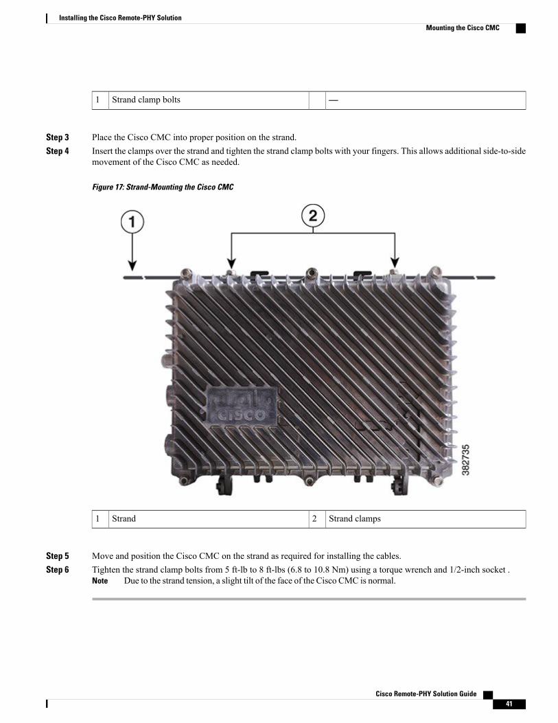
Step 3 Place the Cisco CMC into proper position on the strand.Step 4 Insert the clamps over the strand and tighten the strand clamp bolts with your fingers. This allows additional side-to-side
movement of the Cisco CMC as needed.
Figure 17: Strand-Mounting the Cisco CMC
Strand clamps2Strand1
Step 5 Move and position the Cisco CMC on the strand as required for installing the cables.Step 6 Tighten the strand clamp bolts from 5 ft-lb to 8 ft-lbs (6.8 to 10.8 Nm) using a torque wrench and 1/2-inch socket .
Due to the strand tension, a slight tilt of the face of the Cisco CMC is normal.Note
Cisco Remote-PHY Solution Guide 41
Installing the Cisco Remote-PHY SolutionMounting the Cisco CMC

Opening the Cisco CMCInstallation or maintenance of the Cisco CMC requires opening the housing to access the internal components.
Before You Begin
Have the following tools ready before performing this task:
• Torque wrench
Step 1 Loosen the 1/2-inch closure bolts on the Cisco CMC lid using a torque wrench.
Figure 18: Location of the Closure Bolts on the Cisco CMC
Cisco Remote-PHY Solution Guide42
Installing the Cisco Remote-PHY SolutionOpening the Cisco CMC

—Closure bolts1
Step 2 Open the Cisco CMC lid.The closure bolts remain attached to the Cisco CMC lid after opening the housing.Note
Removing and Installing the Accessories on the Cisco CMCThis section provides information on how to remove and install the following accessories located inside theCisco CMC.
IllustrationDescriptionAccessory
An attenuator pad produces flat (even) lossacross the forward and reverse frequencyspectrums. It is used during the stationbalancing to adjust signal levels. The loss (indB) produced by an attenuator pad is equalto the value printed on the top of theattenuator pad. An attenuator pad with 75 Ωprinted on the top works as a 75 ohmterminator.
Do not change the attenuatorpads, unless specified by thesystem design.
Important
Attenuator pads
An equalizer produces linear tilt. It must beused on the Cisco CMC if the output tilt doesnot have the desired output tilt. The EQ valuespecified on the equalizer is the amount of tiltfrom lowest to highest frequency (52 to 1002MHz).
Equalizers
Cisco Remote-PHY Solution Guide 43
Installing the Cisco Remote-PHY SolutionRemoving and Installing the Accessories on the Cisco CMC

IllustrationDescriptionAccessory
A splitter splits the RF input signal to feedtwo RF output ports. It is used for configuringthe 4-way RF configuration on theCisco CMC.
Signal director—Splitter
A jumper routes the RF input signal to the RFoutput port. It is used for configuring the2-way RF configuration on the Cisco CMC.
Signal director—Jumper
An AC shunt is used for configuring thepower direction in the Cisco CMC with the60VAC power supply unit. Use the red ACshunt for the RF input port and black ACshunts for the RF output ports.
Remove all the AC shunts if theyare installed in the Cisco CMCbefore connecting the coaxialcables to the F-connectors.
Warning
Do not use AC shunts in theCisco CMCwith the 220VAC powersupply unit.
Note
AC shunts
Cisco Remote-PHY Solution Guide44
Installing the Cisco Remote-PHY SolutionRemoving and Installing the Accessories on the Cisco CMC

These accessories can be removed and installed in the Cisco CMC through the cutouts in the base cover.
Figure 19: Location of the Accessories Inside the Cisco CMC
Attenuator pads4Base cover1
Signal directors5AC shunt for the CATV IN port2
AC shunts for the RF output ports6Equalizers3
Before You Begin
Open the Cisco CMC lid. See Opening the Cisco CMC, on page 42.
Step 1 Remove the existing accessory from the slot if it is already installed.Step 2 Align all the pins on the accessory with the pin holes in the appropriate accessory slot.Step 3 Insert the accessory into the slot.
What to Do Next
Close the Cisco CMC lid. See Closing the Cisco CMC, on page 74.
Cisco Remote-PHY Solution Guide 45
Installing the Cisco Remote-PHY SolutionRemoving and Installing the Accessories on the Cisco CMC

Installing the Coaxial Cables on the Cisco CMCCoaxial cables carry the forward-path RF signal input and outputs, and reverse-path RF signal inputs on theCisco CMC. The coaxial cables can also supply 25 to 90VAC power input to the Cisco CMC. You can installup to:
• Five coaxial cables on the Cisco CMC with the 220VAC Power Supply Unit (PSU)
• Six coaxial cables on the Cisco CMC with the 60VAC PSU
Trimming the Center Conductor on the F-ConnectorF-connectors are used for the RF connections on the Cisco CMC. The Cisco CMC supports PG11 and 5/8"F-connectors. The Cisco CMC has a strip on the external housing that shows the center conductor pin trimlength for the F-connector. You must trim the center conductor pin if it extends beyond the strip line on theCisco CMC before inserting it into the RF ports.
Before You Begin
Have the following tools ready before performing this task:
• Heavy-duty wire cutter
• Deburring tool
Step 1 Place the F-connector above the CATV IN port on the Cisco CMC so that the seal shoulder aligns with the strip.Step 2 Perform one of the following:
• For the 5/8" F-connector, if the center conductor pin extends beyond the 5/8”-strip line, trim the pin to the 5/8”-stripline (35 mm) using a heavy-duty wire cutter.
• For the PG11 F-connector, if the center conductor pin extends beyond the PG11-strip line, trim the pin to thePG11-strip line (32 mm) using a heavy-duty wire cutter.
Cisco Remote-PHY Solution Guide46
Installing the Cisco Remote-PHY SolutionInstalling the Coaxial Cables on the Cisco CMC
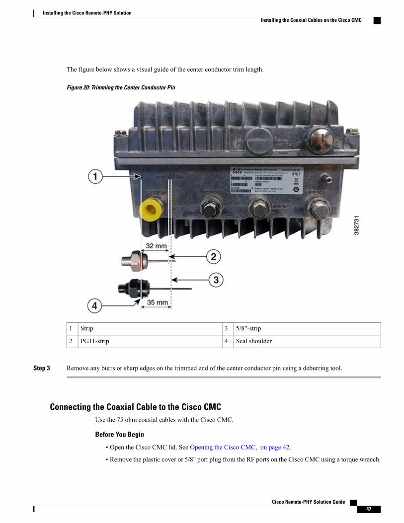
The figure below shows a visual guide of the center conductor trim length.
Figure 20: Trimming the Center Conductor Pin
5/8"-strip3Strip1
Seal shoulder4PG11-strip2
Step 3 Remove any burrs or sharp edges on the trimmed end of the center conductor pin using a deburring tool.
Connecting the Coaxial Cable to the Cisco CMCUse the 75 ohm coaxial cables with the Cisco CMC.
Before You Begin
• Open the Cisco CMC lid. See Opening the Cisco CMC, on page 42.
• Remove the plastic cover or 5/8" port plug from the RF ports on the Cisco CMC using a torque wrench.
Cisco Remote-PHY Solution Guide 47
Installing the Cisco Remote-PHY SolutionInstalling the Coaxial Cables on the Cisco CMC

• Have the following tools ready before performing this task:
◦Heavy-duty wire cutter
◦Torque wrench
◦Slot screwdriver
Step 1 Trim the center conductor pin with a heavy-duty wire cutter if it extends beyond the strip line on the Cisco CMC. SeeTrimming the Center Conductor on the F-Connector, on page 46.
Step 2 Lightly loosen the seizure screw, do not remove it. The figure below shows the location of the seizure screw inside theCisco CMC.
Figure 21: Location of Seizure Screw
—Seizure screw1
Cisco Remote-PHY Solution Guide48
Installing the Cisco Remote-PHY SolutionInstalling the Coaxial Cables on the Cisco CMC

Step 3 To use the PG11 F-connector, remove the PG11-to-5/8" adapter plug from the RF port using a torque wrench. The figurebelow shows the PG11-to-5/8" adapter plug.
Figure 22: Removing the PG11-to-5/8" Adapter Plug
PG11-to-5/8" adapter plug2RF port1
Step 4 Insert the F-connector into the RF port. Tighten the connector nut with a torque wrench.Step 5 Tighten the seizure screw from 2 ft-lb to 5 ft-lb (2.7 Nm to 6.8 Nm) using a slot screwdriver.Step 6 Remove the AC shunt for the RF port to prevent damage to the equipment that is connected to the other end of the coaxial
cable.Step 7 Connect the coaxial cable to the F-connector.Step 8 Reinstall the AC shunt for the RF port.Step 9 Repeat Step 1, on page 48 through Step 7, on page 49 for each RF port used.Step 10 Check if RF signal is present at the unused RF ports and perform one of the following:
• If RF signal is present, insert a 75 ohm terminator into the RF port and tighten according to the manufacturerspecifications.
Cisco Remote-PHY Solution Guide 49
Installing the Cisco Remote-PHY SolutionInstalling the Coaxial Cables on the Cisco CMC
• If RF signal is not present, insert a 5/8" port plug into the RF port and tighten from 5 ft-lb to 8 ft-lb (6.8 Nm to10.8 Nm) using a torque wrench.
What to Do Next
Close the Cisco CMC lid. See Closing the Cisco CMC, on page 74.
Installing a Fiber Adapter on the Cisco CMCThe Cisco CMC supports two types of fiber adapters:
• SC/APC-LC/APC fiber adapter
• SC/APC-SC/APC fiber adapter
The Cisco CMC contains two pre-installed SC/APC-SC/APC fiber adapters. Perform this procedure to installadditional fiber adapters.
Cisco Remote-PHY Solution Guide50
Installing the Cisco Remote-PHY SolutionInstalling a Fiber Adapter on the Cisco CMC

Before You Begin
Open the Cisco CMC lid. See Opening the Cisco CMC, on page 42.
Step 1 Align the fiber adapter with the slot.Step 2 Insert the fiber adapter through the slot as shown in the figure below until you feel the fiber adapter lock into the slot.
Figure 23: Installing the Fiber Adapter on the Cisco CMC
—SC/APC-SC/APC fiber adapter1
Step 3 Remove the dust plug from the fiber adapter and connect the optical fibers. See Connecting the Optical Fibers to theSFP Module, on page 53 and Connecting the Optical Fibers to the FRx, on page 58.
What to Do Next
Close the Cisco CMC lid. See Closing the Cisco CMC, on page 74.
Cisco Remote-PHY Solution Guide 51
Installing the Cisco Remote-PHY SolutionInstalling a Fiber Adapter on the Cisco CMC

Installing an SFP Module on the Cisco CMCThe Cisco CMC supports Gigabit Ethernet SFP and Ethernet Passive Optical Network (EPON) SFP.
Before You Begin
Open the Cisco CMC lid. See Opening the Cisco CMC, on page 42.
Step 1 Remove the SFP module from its protective packaging.Step 2 Locate the transmit (Tx) and receive (Rx) markings on the top side of the SFP module.
On some SFPmodules, the Tx and Rxmarkings may be replaced by arrowheads pointing from the SFP connector(transmit direction or Tx) and towards the connector (receive direction or Rx).
Note
Step 3 Align the SFP module with the socket opening.Step 4 Insert the SFP module into the socket until you feel the SFP module connector lock into the socket connector and then
close the SFP latch.
Figure 24: Installing the SFP module on the Cisco CMC
SFP module2SFP port1
Step 5 Remove the dust plug from the SFP module and save it for future use.For optical SFP module, before you remove the dust plugs and make any optical connections, observe theseguidelines:
Note
• Do not remove the protective dust plugs on the SFP module until you are ready to make a connection.
• Inspect and clean the connector end-faces just before you make any connections.
• Grasp the connector housing to plug or unplug a optical.
Cisco Remote-PHY Solution Guide52
Installing the Cisco Remote-PHY SolutionInstalling an SFP Module on the Cisco CMC

Step 6 Perform one of the following:
• For the optical SFP module, connect the optical fibers to the SFP module. See Connecting the Optical Fibers tothe SFP Module, on page 53.
• For the Gigabit Ethernet SFPmodule, connect the RJ-45 cable to the Gigabit Ethernet SFPmodule. See Connectingthe RJ-45 Cables to the Cisco CMC, on page 55.
What to Do Next
Close the Cisco CMC lid. See Closing the Cisco CMC, on page 74.
Connecting the Optical Fibers to the SFP Module
Before You Begin
• Open the Cisco CMC lid. See Opening the Cisco CMC, on page 42.
• Install the SFP module on the Cisco CMC. See Installing an SFP Module on the Cisco CMC, on page52.
Cisco Remote-PHY Solution Guide 53
Installing the Cisco Remote-PHY SolutionConnecting the Optical Fibers to the SFP Module

• Remove the 5/8" port plug from the fiber port on the Cisco CMC using a torque wrench
Step 1 Insert the optical fiber into the fiber port.Step 2 Secure the optical fibers using the cable clips and insert the optical fiber connector into the SFP port until it clicks and
locks into place and as shown in the figure below:
Figure 25: Connecting Optical Fiber to the SFP Port
Optical fiber3Cable clips1
Optical fiber connector4Fiber port2
Step 3 Seal the fiber port with an appropriate gland to waterproof the port.
Cisco Remote-PHY Solution Guide54
Installing the Cisco Remote-PHY SolutionConnecting the Optical Fibers to the SFP Module

What to Do Next
Close the Cisco CMC lid. See Closing the Cisco CMC, on page 74.
Connecting the RJ-45 Cables to the Cisco CMCUse the PG16 gland to connect the RJ-45 cable to the Cisco CMC.
Figure 26: PG16 Gland
Sealing nut3Body1
—Seal2
The Cisco CMC supports two types of PG16 glands for the RJ-45 port:
• PG16 gland with one hole for single Ethernet connection
• PG16 gland with two holes for dual Ethernet connection
Before You Begin
• Open the Cisco CMC lid. See Opening the Cisco CMC, on page 42.
• Have the following tools ready before performing this task:
◦Torque wrench
Step 1 Remove the PG16 port plug or the PG16 gland from the RJ-45 port on the Cisco CMC if it is already installed.
Cisco Remote-PHY Solution Guide 55
Installing the Cisco Remote-PHY SolutionConnecting the RJ-45 Cables to the Cisco CMC
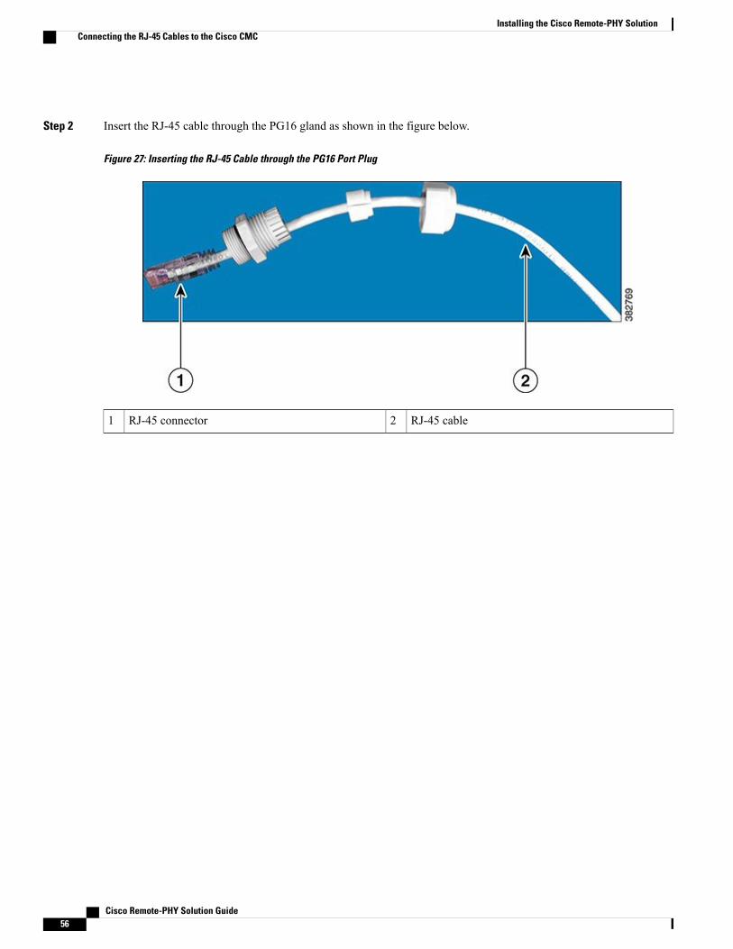
Step 2 Insert the RJ-45 cable through the PG16 gland as shown in the figure below.
Figure 27: Inserting the RJ-45 Cable through the PG16 Port Plug
RJ-45 cable2RJ-45 connector1
Cisco Remote-PHY Solution Guide56
Installing the Cisco Remote-PHY SolutionConnecting the RJ-45 Cables to the Cisco CMC

Step 3 Insert the RJ-45 connector through the RJ-45 port on the Cisco CMC.Step 4 Insert the RJ-45 connector into the Gigabit Ethernet port until it clicks and locks into place.
Figure 28: Connecting the RJ-45 Connector to the Cisco CMC
RJ-45 connector3PG16 gland1
RJ-45 Gigabit Ethernet port4RJ-45 cable2
Step 5 Tighten the PG16 gland into the RJ-45 port using a torque wrench (4.44 ft-lb) and then tighten the dome cap using atorque wrench (2.44 ft-lb).
What to Do Next
Close the Cisco CMC lid. See Closing the Cisco CMC, on page 74.
Cisco Remote-PHY Solution Guide 57
Installing the Cisco Remote-PHY SolutionConnecting the RJ-45 Cables to the Cisco CMC

Connecting the Optical Fibers to the FRx
Before You Begin
• Open the Cisco CMC lid. See Opening the Cisco CMC, on page 42.
• Ensure that the Forward Optical Receiver Module (FRx) module is installed on the Cisco CMC. Toinstall the FRx on the Cisco CMC, contact the Cisco Technical Assistance Center (TAC) for furtherassistance.
Cisco Remote-PHY Solution Guide58
Installing the Cisco Remote-PHY SolutionConnecting the Optical Fibers to the FRx

• Remove the 5/8" port plug from the fiber port on the Cisco CMC using a torque wrench.
Step 1 Insert the optical fiber into the fiber port.Step 2 Secure the optical fiber using the cable clips and insert the optical fiber connector to the fiber adapter as shown in the
figure below:
Figure 29: Connecting Optical Fiber to the Fiber Adapter
Fiber adapter3FRx1
Cable clip4Optical fiber2
Cisco Remote-PHY Solution Guide 59
Installing the Cisco Remote-PHY SolutionConnecting the Optical Fibers to the FRx
Step 3 Seal the fiber port with an appropriate gland to waterproof the port.
What to Do Next
Close the Cisco CMC lid. See Closing the Cisco CMC, on page 74.
Connecting I/O to the Cisco CMCThe Cisco CMC supports two types of I/O configurations:
• Forward-path I/O configurations
• Reverse-path I/O configurations
Forward-Path I/O Configurations
Forward-path refers to the signals received at the Cisco CMC from the headend. These signals are amplifiedin the Cisco CMC and routed to the subscribers through the cable modems. The Cisco CMC supports thefollowing forward-path RF configurations:
• 4-way forward output RF configuration (default RF configuration)
• 2-way forward output RF configuration
Reverse-Path I/O Configurations
Reverse-path refers to the signals received at the Cisco CMC from the cablemodem. These signals are amplifiedin Cisco CMC and returned to the headend optically through the fiber portion of the network. The reverse-pathRF configuration is not used in all networks. The Cisco CMC supports the following reverse-path RFconfigurations:
• 4-way reverse input RF configuration (default RF configuration)
• 2-way reverse input RF configuration
The following sections provide information on how to enable the different RF configurations on the Cisco CMC:
Enabling the 4-Way Forward Output RF Configuration on the Cisco CMC
Before You Begin
Open the Cisco CMC lid. See Opening the Cisco CMC, on page 42.
Step 1 Remove all the AC shunts installed on the Cisco CMC. Removing the AC shunts prevents damage to the equipment thatis connected on the other end of the coaxial cable. Power surge to the components and F-connectors is reduced whenthe AC shunts are removed.
The RF connectors and housing seizure assemblies can get damaged if the AC shunts are not removed fromthe Cisco CMC before installing or removing the components from the housing.
Caution
Cisco Remote-PHY Solution Guide60
Installing the Cisco Remote-PHY SolutionConnecting I/O to the Cisco CMC

Step 2 Insert the signal director—splitter to provide the RF output to the four RF output ports.
Figure 30: 4-Way Forward Output RF Configuration
Reverse input pad 28Reverse output test point1
Splitter 29Forward equalizer 22
Forward test point 210Forward pad 23
Reverse output pad11Downstream input port4
Forward test point 112Forward pad 15
Splitter 113Forward equalizer 16
Reverse input pad 114Upstream input port7
Step 3 Perform one of the following:
• If FRx is installed on the Cisco CMC, connect the optical input signal to the FRx. See Connecting the OpticalFibers to the FRx, on page 58.
Cisco Remote-PHY Solution Guide 61
Installing the Cisco Remote-PHY SolutionConnecting I/O to the Cisco CMC

• If FRx is not installed on the Cisco CMC, insert the F-connector into the CATV IN port. Connect the coaxial cablefrom the node or amplifier in the HFC network to the F-connector. See Installing the Coaxial Cables on theCisco CMC, on page 46.
Step 4 Insert the F-connector into each RF output port (Port 1 through Port 4). Connect the coaxial cable from each F-connectorto the cable modem. See Installing the Coaxial Cables on the Cisco CMC, on page 46.
Step 5 Reinstall the AC shunts on the Cisco CMC.
What to Do Next
Close the Cisco CMC lid. See Closing the Cisco CMC, on page 74.
Enabling the 2-Way Forward Output RF Configuration on the Cisco CMC
Before You Begin
Open the Cisco CMC lid. See Opening the Cisco CMC, on page 42.
Step 1 Remove all the AC shunts installed on the Cisco CMC. Removing the AC shunts prevents damage to the equipment thatis connected on the other end of the coaxial cable. Power surge to the components and F-connectors is reduced whenthe AC shunts are removed.
The RF connectors and housing seizure assemblies can get damaged if the AC shunts are not removed fromthe Cisco CMC before installing or removing the components from the housing.
Caution
Cisco Remote-PHY Solution Guide62
Installing the Cisco Remote-PHY SolutionConnecting I/O to the Cisco CMC

Step 2 Insert the signal director—jumper to provide the RF output to two RF output ports.
Figure 31: 2-Way Forward Output RF Configuration
Reverse input pad 28Reverse output test point1
Jumper 29Forward equalizer 22
Forward test point 210Forward pad 23
Reverse output pad11Downstream input port4
Forward test point 112Forward pad 15
Jumper 113Forward equalizer 16
Reverse input pad 114Upstream input port7
Step 3 Perform one of the following:
• If FRx is installed on the Cisco CMC, connect the optical input signal to the FRx. See Connecting the OpticalFibers to the FRx, on page 58.
• If FRx is not installed on the Cisco CMC, insert the F-connector into the CATV IN port. Connect the coaxial cablefrom the node or amplifier in the HFC network to the F-connector. See Installing the Coaxial Cables on theCisco CMC, on page 46.
Step 4 Insert the F-connector into two RF output ports. Connect the coaxial cable from each F-connector to the cable modem.See Installing the Coaxial Cables on the Cisco CMC, on page 46.
Cisco Remote-PHY Solution Guide 63
Installing the Cisco Remote-PHY SolutionConnecting I/O to the Cisco CMC

We recommend that you provide the RF output through the Port 1 and Port 4 for the 2-way forward output RFconfiguration.
Note
Step 5 Reinstall the AC shunts on the Cisco CMC.
What to Do Next
Close the Cisco CMC lid. See Closing the Cisco CMC, on page 74.
Enabling the 4-Way Reverse Input RF Configuration on the Cisco CMC
Before You Begin
Open the Cisco CMC lid. See Opening the Cisco CMC, on page 42.
Step 1 Remove all the AC shunts installed on the Cisco CMC. Removing the AC shunts prevents damage to the equipment thatis connected on the other end of the coaxial cable. Power surge to the components and F-connectors is reduced whenthe AC shunts are removed.
The RF connectors and housing seizure assemblies can get damaged if the AC shunts are not removed fromthe Cisco CMC before installing or removing the components from the housing.
Caution
Step 2 Insert the signal director—splitter to provide the RF input from the four RF output ports.
Figure 32: 4-Way Reverse Input RF Configuration
Reverse input pad 28Reverse output test point1
Cisco Remote-PHY Solution Guide64
Installing the Cisco Remote-PHY SolutionConnecting I/O to the Cisco CMC

Splitter 29Forward equalizer 22
Forward test point 210Forward pad 23
Reverse output pad11Downstream input port4
Forward test point 112Forward pad 15
Splitter 113Forward equalizer 16
Reverse input pad 114Upstream input port7
Step 3 Insert the F-connector into each RF output port (Port 1 through Port 4). Connect the coaxial cables from the cable modemsto each F-connectors. See Installing the Coaxial Cables on the Cisco CMC, on page 46.
Step 4 Reinstall the AC shunts on the Cisco CMC.Step 5 Perform one of the following:
• If the optical SFP module is installed on the Cisco CMC, connect the optical fiber from the SFP module to thedigital fiber network. See Connecting the Optical Fibers to the SFP Module, on page 53.
• If the optical SFP module is not installed on the Cisco CMC, connect the RJ-45 cable from the Gigabit Ethernetport to the PON module in the digital fiber network. See Connecting the RJ-45 Cables to the Cisco CMC, on page55.
What to Do Next
Close the Cisco CMC lid. See Closing the Cisco CMC, on page 74.
Enabling the 2-Way Reverse Input RF Configuration on the Cisco CMC
Before You Begin
Open the Cisco CMC lid. See Opening the Cisco CMC, on page 42.
Step 1 Remove all the AC shunts installed on the Cisco CMC. Removing the AC shunts prevents damage to the equipment thatis connected on the other end of the coaxial cable. Power surge to the components and F-connectors is reduced whenthe AC shunts are removed.
The RF connectors and housing seizure assemblies can get damaged if the AC shunts are not removed fromthe Cisco CMC before installing or removing the components from the housing.
Caution
Cisco Remote-PHY Solution Guide 65
Installing the Cisco Remote-PHY SolutionConnecting I/O to the Cisco CMC

Step 2 Insert the signal director—jumper to provide the RF input from the two RF output ports.
Figure 33: 2-Way Reverse Input RF Configuration
Reverse input pad 28Reverse output test point1
Jumper 29Forward equalizer 22
Forward test point 210Forward pad 23
Reverse output pad11Downstream input port4
Forward test point 112Forward pad 15
Jumper 113Forward equalizer 16
Reverse input pad 114Upstream input port7
Step 3 Insert the F-connector into two RF output ports. Connect the coaxial cable from the cable modems to each F-connector.See Installing the Coaxial Cables on the Cisco CMC, on page 46.
We recommend that you provide the RF input through the Port 1 and Port 4 for the 2-way reverse input RFconfiguration.
Note
Step 4 Reinstall the AC shunts on the Cisco CMC.Step 5 Perform one of the following:
• If the optical SFP module is installed on the Cisco CMC, connect the optical fiber from the SFP module to thedigital fiber network. See Connecting the Optical Fibers to the SFP Module, on page 53.
Cisco Remote-PHY Solution Guide66
Installing the Cisco Remote-PHY SolutionConnecting I/O to the Cisco CMC

• If the optical SFP module is not installed on the Cisco CMC, connect the RJ-45 cable from the Gigabit Ethernetport to the PON module in the digital fiber network. See Connecting the RJ-45 Cables to the Cisco CMC, on page55.
What to Do Next
Close the Cisco CMC lid. See Closing the Cisco CMC, on page 74.
Powering Up the Cisco CMC
Before working on equipment that is connected to power lines, remove jewelry (including rings,necklaces, and watches). Metal objects will heat up when connected to power and ground and cancause serious burns or weld the metal object to the terminals. Statement 43.
Warning
This equipment must be grounded. Never defeat the ground conductor or operate the equipmentin the absence of a suitably installed ground conductor. Contact the appropriate electrical inspectionauthority or an electrician if you are uncertain that suitable grounding is available. Statement 1024
Warning
This unit might have more than one power supply connection. All connections need to be removedto de-energize the unit. Statement 1028
Warning
Before powering up the Cisco CMC, you must provide an adequate ground connection for the equipment.
The Cisco CMC available in the following variants of the power supply unit (PSU):
• Cisco CMC with the 220VAC PSU
• Cisco CMC with the 60VAC PSU
The following sections provide information on how to ground and power up the Cisco CMC:
Grounding the Cisco CMCGrounding the equipment is mandatory for the Cisco CMC with the 60VAC PSU and optional for theCisco CMC with the 220VAC PSU.
Use copper conductors only. Statement 1025.Warning
Cisco Remote-PHY Solution Guide 67
Installing the Cisco Remote-PHY SolutionPowering Up the Cisco CMC

This equipment must be grounded. Never defeat the ground conductor or operate the equipmentin the absence of a suitably installed ground conductor. Contact the appropriate electrical inspectionauthority or an electrician if you are uncertain that suitable grounding is available. Statement 1024.
Warning
When installing or replacing the unit, the ground connection must always be made first anddisconnected last. Statement 1046.
Warning
Before You Begin
Have the following tools ready before performing this task:
• M4 (metric) panhead Philips screwdriver
Step 1 Power down the Cisco CMC.Step 2 Connect one end of an 18-gauge or larger wire to the grounding screw on the Cisco CMC using the M4 panhead Phillips
screwdriver.
Figure 34: Location of the Grounding Screw on the Cisco CMC
—Grounding screw1
Step 3 Connect the other end of the grounding wire to an appropriate ground source.
Cisco Remote-PHY Solution Guide68
Installing the Cisco Remote-PHY SolutionPowering Up the Cisco CMC

Powering Up the Cisco CMC with the 220VAC PSU
Before You Begin
Open the Cisco CMC lid. See Opening the Cisco CMC, on page 42.
Step 1 Ensure that the 220VAC power source is switched off.Step 2 Connect the power cord on the Cisco CMC to the 220VAC power source.
Figure 35: Connecting 220VAC Power to the Cisco CMC
—Power cord1
Step 3 Switch on the power source to power up the Cisco CMC.
Cisco Remote-PHY Solution Guide 69
Installing the Cisco Remote-PHY SolutionPowering Up the Cisco CMC

What to Do Next
Verify if the PWRLED illuminates (green) to ensure that the Cisco CMC is powered up. Close the Cisco CMClid. See Closing the Cisco CMC, on page 74.
Powering Up the Cisco CMC with the 60VAC PSUThis section describes how to power up the Cisco CMC with the 60VAC PSU:
Connecting 60VAC Power to the Cisco CMC Through the Power Port
Before You Begin
• Ensure that the grounding wire is installed before powering up the Cisco CMC. See Grounding theCisco CMC, on page 67.
• The F-connector used for connecting the 60VAC power must meet the following requirements:
◦Impedance of 75 ohms
◦IP rating of IP67
◦Pass through current not greater than 8A
• Open the Cisco CMC lid. See Opening the Cisco CMC, on page 42.
Restrictions
You must supply 60VAC power to the Cisco CMC with 60VAC PSU using only one coaxial cable.Connecting more than one coaxial cable with the 60VAC power damages the Cisco CMC. If you areconnecting a modem to the port that has a black AC shunt, ensure to use combiners in the network toisolate pass-through power to prevent accidental injury.
Warning
Restrictions
Cisco Remote-PHY Solution Guide70
Installing the Cisco Remote-PHY SolutionPowering Up the Cisco CMC

F-connector is not capable of handling pass through current greater than 8A. For 15A pass through currentapplications, ensure that the chosen connector - rather than F-connector - is capable of safely passing thedesired current
Warning
Step 1 Ensure that the power source is switched off.Step 2 Install the F-connector in the power port. See Connecting the Coaxial Cable to the Cisco CMC, on page 47.
Figure 36: Connecting 60VAC Power to the Cisco CMC Through the Power Port
—Power port1
Step 3 Connect the coaxial cable to the F-connector.Step 4 Connect the other end of the coaxial cable to a 60VAC power source.Step 5 Switch on the power source to power up the Cisco CMC.
Cisco Remote-PHY Solution Guide 71
Installing the Cisco Remote-PHY SolutionPowering Up the Cisco CMC

What to Do Next
Verify if the PWRLED illuminates (green) to ensure that the Cisco CMC is powered up. Close the Cisco CMClid. See Closing the Cisco CMC, on page 74.
Connecting 60VAC Power to the Cisco CMC Through the RF Port
For the Cisco CMC with the 60VAC PSU, the power direction is configured by installing the AC shunts forthe RF ports through which the AC power is passed. Use the red AC shunt for the RF input port and blackAC shunts for the RF output ports.
Figure 37: Location of AC Shunts on the Cisco CMC
AC shunt for the RF output port (Port 2)4AC shunt for the CATV IN port1
AC shunt for the RF output port (Port 1)5AC shunt for the RF output port (Port 4)2
—AC shunt for the RF output port (Port 3)3
Before You Begin
• Ensure that the grounding wire is installed before powering up the Cisco CMC. See Grounding theCisco CMC, on page 67.
• The F-connector used for connecting the 60VAC power must meet the following requirements:
◦Impedance of 75 ohms
◦IP rating of IP67
◦Pass through current not greater than 8A
• Open the Cisco CMC lid. See Opening the Cisco CMC, on page 42.
Cisco Remote-PHY Solution Guide72
Installing the Cisco Remote-PHY SolutionPowering Up the Cisco CMC

Restrictions
You must supply 60VAC power to the Cisco CMC with 60VAC PSU using only one coaxial cable.Connecting more than one coaxial cable with the 60VAC power damages the Cisco CMC. If you areconnecting a modem to the port that has a black AC shunt, ensure to use combiners in the network toisolate pass-through power to prevent accidental injury.
Warning
Restrictions
F-connector is not capable of handling pass through current greater than 8A. For 15A pass through currentapplications, ensure that the chosen connector - rather than F-connector - is capable of safely passing thedesired current
Warning
Step 1 Ensure that the power source is switched off.Step 2 Install the F-connector in the CATV IN and four RF output ports (Port 1 through Port 4). See Connecting the Coaxial
Cable to the Cisco CMC, on page 47.Each RF port can support up to 8 A. Ensure that the total current from all the four RF output ports and Cisco CMCdoes not exceed 8 A.
Note
Figure 38: Connecting 60VAC Power to the Cisco CMC Through the RF Port
RF output ports2CATV IN port1
Cisco Remote-PHY Solution Guide 73
Installing the Cisco Remote-PHY SolutionPowering Up the Cisco CMC

Step 3 Remove all the AC shunts installed on the Cisco CMC.Step 4 Connect the coaxial cables to the F-connectors.Step 5 Insert the black AC shunts for the RF ports that need to be supplied with 60VAC power from the Cisco CMC.Step 6 Insert the red AC shunt for the RF port that supplies 60VAC power to the Cisco CMC. Connect the other end of the
coaxial cable to a 60VAC power source.Step 7 Switch on the power source to power up the Cisco CMC.
What to Do Next
Verify if the PWRLED illuminates (green) to ensure that the Cisco CMC is powered up. Close the Cisco CMClid. See Closing the Cisco CMC, on page 74.
Closing the Cisco CMCProper housing closure is important to maintain the Cisco CMC in good working condition. Proper closureensures a good seal against the environment and protects the internal modules.
Avoid moisture damage and RF leakage. Follow the procedure exactly as shown below to ensure a properseal.
Caution
Cisco Remote-PHY Solution Guide74
Installing the Cisco Remote-PHY SolutionClosing the Cisco CMC

The Cisco CMC has waterproof rubber and EMI gasket to seal the equipment.
Figure 39: Location of the Waterproof Rubber and EMI Gasket on the Cisco CMC
EMI gasket2Waterproof rubber1
Before You Begin
• Ensure that the waterproof rubber and EMI gasket on the Cisco CMC are not worn out. Wipe off anyexcess dirt and debris. If the waterproof rubber or EMI gasket is worn out, contact the Cisco TechnicalAssistance Center (TAC) for further assistance.
• Have the following tools ready before performing this task:
◦Torque wrench
◦Hex driver or ratchet
Step 1 Close the lid.Ensure that all the cables are out of the way when closing thelid.
Caution
Cisco Remote-PHY Solution Guide 75
Installing the Cisco Remote-PHY SolutionClosing the Cisco CMC
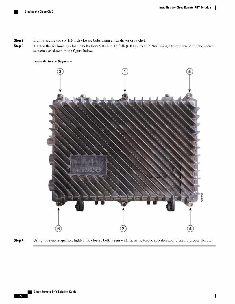
Step 2 Lightly secure the six 1/2-inch closure bolts using a hex driver or ratchet.Step 3 Tighten the six housing closure bolts from 5 ft-lb to 12 ft-lb (6.8 Nm to 16.3 Nm) using a torque wrench in the correct
sequence as shown in the figure below.
Figure 40: Torque Sequence
Step 4 Using the same sequence, tighten the closure bolts again with the same torque specification to ensure proper closure.
Cisco Remote-PHY Solution Guide76
Installing the Cisco Remote-PHY SolutionClosing the Cisco CMC

Installing the Cisco uBR-MC3GX60V-RPHY Line CardThis section provides information on how to install the Cisco uBR-MC3GX60V-RPHY line card.
Removing an SFP Module from the Existing Line Card
Before You Begin
Have the following tools and supplies ready before performing this task:
• Antistatic bag
• Dust plug, if required
• ESD-preventive wrist strap
Removing and inserting an SFPmodule frequently can damage the SFPmodule. Do not remove and insertthe SFP modules unless absolutely necessary.
Caution
Step 1 Disconnect all the network cables from the SFP module connector. For optical SFP module, immediately reinstall thedust plugs in the SFP optical bores.
We recommend that you do not remove the SFPmodule with the fiber-optic cables attached to it as it can damagethe cable, cable connector, and optical interfaces in the SFP module.
Note
Step 2 Unlock and remove the SFP module from the socket connector using one of the following:
• If the SFP module has a Mylar tab latch, pull the tab gently in a slightly downward direction until the SFP moduledisengages from the socket connector, and then pull the SFP module straight out of the socket. Do not twist or pullthe Mylar tab as it can detach from the SFP module.
• If the SFP module has an Actuator button latch, gently press the Actuator button on the front of the SFP moduleuntil it clicks and the latch mechanism releases the SFP module from the socket connector. Grasp the Actuatorbutton between your thumb and index finger, and carefully pull the SFP module straight from the socket.
• If the SFP module has a Bale-clasp latch, pull the bale to eject the SFP module from the socket. If the Bale-clasplatch is obstructed and you cannot use your index finger to open it, use a small, flat-blade screwdriver or a longnarrow instrument to open the bale-clasp latch. Grasp the SFP module between your thumb and index finger, andcarefully remove it from the socket.
Step 3 Place the removed SFP module in an antistatic bag.Step 4 Insert a dust plug into each unused Gigabit Ethernet port.
What to Do Next
• To remove the existing line card, see Removing the Existing Line Card from the Card Slot, on page78.
Cisco Remote-PHY Solution Guide 77
Installing the Cisco Remote-PHY SolutionInstalling the Cisco uBR-MC3GX60V-RPHY Line Card

• To install an SFPmodule on the Cisco uBR-MC3GX60V-RPHY line card, see Installing an SFPModuleon the Cisco uBR-MC3GX60V-RPHY Line Card, on page 82
Removing the Existing Line Card from the Card Slot
Before You Begin
• Remove the SFPmodule from the line card. See Removing an SFPModule from the Existing Line Card,on page 77.
• Delete the existing configurations on the PRE using the no card command.
Have the following tools and supplies ready before performing this task:
• T-10 Torx driver tool or 1/4-inch flathead screwdriver
• Antistatic bag
• Blank card slot cover, if required
• ESD-preventive wrist strap
Step 1 Attach an ESD-preventive wrist strap to your wrist.Step 2 Unscrew the top and bottom captive screws on the line card using a T-10 Torx driver tool or flathead screwdriver.Step 3 Simultaneously pivot both ejector levers away from the line card to disengage the line card from the chassis.Step 4 Slide the line card out of the slot in the chassis. Place it on an antistatic surface or in a static shielding bag with the
component side up.
Cisco Remote-PHY Solution Guide78
Installing the Cisco Remote-PHY SolutionRemoving the Existing Line Card from the Card Slot

Do not drop the line card. Dropping the line card can damage the carrier rails and card guides and preventthe reinstallation.
Caution
Figure 41: Removing the Existing Line Card from the Chassis
ESD-preventive strap2Captive screw1
Cisco Remote-PHY Solution Guide 79
Installing the Cisco Remote-PHY SolutionRemoving the Existing Line Card from the Card Slot

What to Do Next
Perform one of the following:
• Install a new or replacement Cisco uBR-MC3GX60V-RPHY line card, see Installing theCisco uBR-MC3GX60V-RPHY Line Card in the Card Slot.
• Install a Blank card slot cover over the slot and tighten the captive screws, if you are not installing anyline card in the slot. This ensures to keep dust out of the chassis and maintain proper airflow throughthe line card compartment.
Installing the Cisco uBR-MC3GX60V-RPHY Line Card in the Card Slot
Before You Begin
• Ensure that the existing line card or the Blank card slot cover is removed. See Removing the ExistingLine Card from the Card Slot, on page 78.
• Ensure that you attach an ESD-preventive wrist strap to your wrist.
• For Class B emission compliance requirements, the two ferrites available in the CMTS accessory kitmust be installed on the input DC power harness of the chassis. These ferrite beads are clamp-on typeand should be placed as close to the input DC power connector (DC input terminal connector) as possible.
Have the following tools and supplies ready before performing this task:
• Cisco uBR-MC3GX60V-RPHY line card
• T-10 Torx driver tool or 1/4-inch flathead screwdriver
• ESD-preventive wrist strap
Step 1 Attach an ESD-preventive wrist strap to your wrist.Step 2 Choose an available slot (5/0 to 8/0) for the line card and carefully align the upper and lower edges of the
Cisco uBR-MC3GX60V-RPHY line card with the upper and lower guides in the chassis.The Cisco uBR-MC3GX60V-RPHY line card weighs 13 lbs. Use both hands when handling theCisco uBR-MC3GX60V-RPHY line card. Do not drop the line card to avoid damaging the carrier rails. Bentor damaged rails can damage the line card guides and prevent line card installation.When installing line cardsfor the first time, or when all the captive screws of the line card are loose, insert cards first in slot 5/1 andwork towards slot 8/0 to prevent uneven gasket pressure.
Caution
Cisco Remote-PHY Solution Guide80
Installing the Cisco Remote-PHY SolutionInstalling the Cisco uBR-MC3GX60V-RPHY Line Card in the Card Slot

Step 3 Slide the Cisco uBR-MC3GX60V-RPHY line card into the slot until it is firmly seated in the chassis.
Figure 42: Installing the Cisco uBR-MC3GX60V-RPHY Line Card in the Cisco CMTS Chassis
ESD-preventive strap2Captive screw1
Step 4 Close the ejector levers to secure the Cisco uBR-MC3GX60V-RPHY line card.Step 5 Engage and tighten the captive screws with your fingers. Then, use either a T-10 Torx driver tool or a common flathead
screwdriver to tighten the captive screws from 5 to 7 in-lbs.
What to Do Next
To install the SFP module, see Installing an SFP Module on the Cisco uBR-MC3GX60V-RPHY Line Card,on page 82.
Cisco Remote-PHY Solution Guide 81
Installing the Cisco Remote-PHY SolutionInstalling the Cisco uBR-MC3GX60V-RPHY Line Card in the Card Slot

Installing an SFP Module on the Cisco uBR-MC3GX60V-RPHY Line Card
Before You Begin
Ensure that the Cisco uBR-MC3GX60V-RPHY line card is installed in the Cisco CMTS chassis. See Installingthe Cisco uBR-MC3GX60V-RPHY Line Card in the Card Slot, on page 80.
Have the following tools and supplies ready before performing this task:
• Appropriate SFP module
• ESD-preventive wrist strap
For more information on SFP modules that are supported on the Cisco uBR-MC3GX60V-RPHY line card,see SFP Modules for the Cisco uBR-MC3GX60V-RPHY Line Card, on page 17.
Step 1 Attach an ESD-preventive wrist strap to your wrist.Step 2 Remove the SFP module from its protective packaging.Step 3 Locate the transmit (Tx) and receive (Rx) markings on the top side of the SFP module.
On some SFP modules, the Tx and Rx markings might be replaced by arrowheads pointing from the SFPconnector (transmit direction or Tx) and towards the connector (receive direction or Rx).
Note
Step 4 Align the SFP module in front of the socket opening.Step 5 Insert the SFP module into the socket until you feel the SFP module connector snap into the socket connector and then
close the SFP latch.
Cisco Remote-PHY Solution Guide82
Installing the Cisco Remote-PHY SolutionInstalling an SFP Module on the Cisco uBR-MC3GX60V-RPHY Line Card
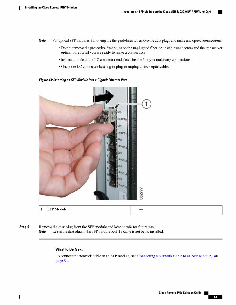
For optical SFPmodules, following are the guidelines to remove the dust plugs andmake any optical connections:Note
• Do not remove the protective dust plugs on the unplugged fiber-optic cable connectors and the transceiveroptical bores until you are ready to make a connection.
• inspect and clean the LC connector end-faces just before you make any connections.
• Grasp the LC connector housing to plug or unplug a fiber-optic cable.
Figure 43: Inserting an SFP Module into a Gigabit Ethernet Port
—SFP Module1
Step 6 Remove the dust plug from the SFP module and keep it safe for future use.Leave the dust plug in the SFPmodule port if a cable is not being installed.Note
What to Do Next
To connect the network cable to an SFP module, see Connecting a Network Cable to an SFP Module, onpage 84.
Cisco Remote-PHY Solution Guide 83
Installing the Cisco Remote-PHY SolutionInstalling an SFP Module on the Cisco uBR-MC3GX60V-RPHY Line Card

Connecting a Network Cable to an SFP ModuleThe following types of cables are used with Cisco uBR-MC3GX60V-RPHY line cards to connect to a switchor an OLT:
• RJ-45 10/100/1000BASE-T copper cable
• Single-mode or multimode fiber-optic cable
Before You Begin
• Ensure that the optical connectors are clean before making the connections. Contaminated connectorscan damage the fiber and cause data errors.
• Ensure that the network cable has an appropriate connector to connect to an appropriate SFP moduleport.
Have the following tools and supplies ready before performing this task:
• Network cable with appropriate connector
• ESD-preventive wrist strap
For more information on the type of connectors supported, see SFP Modules for theCisco uBR-MC3GX60V-RPHY Line Card, on page 17.
Step 1 Attach an ESD-preventive wrist strap to your wrist.Step 2 Remove the dust plug from the SFP module, if already installed.Step 3 Insert the appropriate network cable connector into the SFP module port until it clicks and locks into place to ensure
proper seating.
Cisco Remote-PHY Solution Guide84
Installing the Cisco Remote-PHY SolutionConnecting a Network Cable to an SFP Module

Ensure to insert the network connector completely into the socket.
Note
Figure 44: Gigabit Ethernet Port Cabling
Gigabit Ethernet SFP module2RJ-45 connector1
—LC fiber-optic connector3
Step 4 Insert the other end of the network cable into the receptacle of a switch or an OLT.Step 5 Repeat Step 3, on page 84 to Step 4, on page 85 until all cabling is complete.
Cisco Remote-PHY Solution Guide 85
Installing the Cisco Remote-PHY SolutionConnecting a Network Cable to an SFP Module

Cisco Remote-PHY Solution Guide86
Installing the Cisco Remote-PHY SolutionConnecting a Network Cable to an SFP Module
C H A P T E R 4Configuring the Cisco Remote-PHY Solution
This section provides information on how to configure the Cisco Remote-PHY solution.
• Prerequisites for Configuring the Cisco Remote-PHY Solution, page 87
• Restrictions for Configuring the Cisco Remote-PHY Solution, page 87
• How to Configure the Cisco Remote-PHY Solution, page 87
• Configuration Example for the Cisco Remote-PHY Solution, page 106
Prerequisites for Configuring the Cisco Remote-PHY Solution• The Cisco CMTS must have at least one DOCSIS Timing, Communication, and Control (DTCC) cardconfigured in the DOCSIS Timing Interface (DTI) mode for the Cisco uBR-MC3GX60V-RPHY linecard to work with the CMC device.
Restrictions for Configuring the Cisco Remote-PHY Solution• Adding or removing the upstream or downstream channels in the channel group may trigger theCisco CMC to reset.
• The Cisco uBR-MC3GX60V-RPHY line card supports only static DEPI configuration.
• The Cisco uBR-MC3GX60V-RPHY line card does not support SpectrumManagement, Inter Line CardRF Spanning, and High Availability.
How to Configure the Cisco Remote-PHY SolutionThis section provides information on how to configure the Cisco Remote-PHY solution. These proceduresprovide only the initial and basic configurations for the Cisco Remote-PHY solution.
Cisco Remote-PHY Solution Guide 87

The Cisco CMTS must be operational before beginning the following procedures to configure theCisco Remote-PHY solution.
Note
Configuring the Gigabit Ethernet Interface on the Cisco uBR-MC3GX60V-RPHYLine Card
The Cisco uBR-MC3GX60V-RPHY line card supports six (3 + 3) Gigabit Ethernet links and the links arearranged in three sets of redundant pairs. The links in the pair are modeled as an active-passive Gigabit Ethernetpair and traffic can be quickly switched from the working Gigabit Ethernet link to the standby Gigabit Ethernetlink in the pair. The three active Gigabit Ethernet links are numbered as slotnumber/subslotnumber/0, 2, 4and are mapped to the modular controllers slotnumber/subslotnumber/0, 1, 2 respectively.
The Cisco CMTS creates the following interfaces and controllers during the initialization of theCisco uBR-MC3GX60V-RPHY line card:
• Three Gigabit Ethernet interfaces
• Three modular cable controllers
• 24x3 modular cable interfaces
Each Gigabit Ethernet pair is assigned as follows:
AssignmentGigabit Ethernet pair
Modular cable controller {0}; 0 to 23 channels; 0 to31 bonding groups
Gigabit Ethernet {0, 1} - Gigabit Ethernet interface0
Modular cable controller {1}; 24 to 47 channels; 32to 63 bonding groups
Gigabit Ethernet {2, 3} - Gigabit Ethernet interface2
Modular cable controller {2}; 48 to 71 channels; 64to 95 bonding groups
Gigabit Ethernet {4, 5} - Gigabit Ethernet interface4
Before You Begin
Due to slow link loss detection, we do not recommend using the SFP-GE-Tmodules for primary interfaces.Restriction
DETAILED STEPS
PurposeCommand or Action
Enables privileged EXEC mode.enableStep 1
Cisco Remote-PHY Solution Guide88
Configuring the Cisco Remote-PHY SolutionConfiguring the Gigabit Ethernet Interface on the Cisco uBR-MC3GX60V-RPHY Line Card
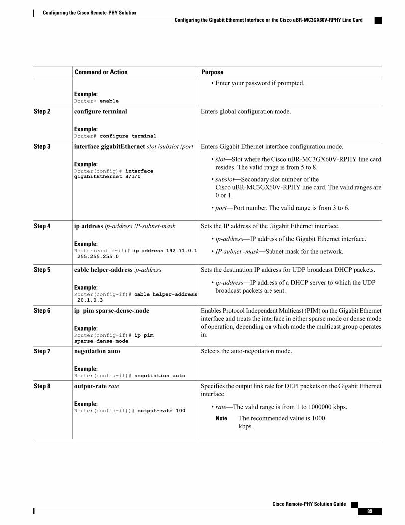
PurposeCommand or Action
Example:Router> enable
• Enter your password if prompted.
Enters global configuration mode.configure terminal
Example:Router# configure terminal
Step 2
Enters Gigabit Ethernet interface configuration mode.interface gigabitEthernet slot /subslot /portStep 3
Example:Router(config)# interfacegigabitEthernet 8/1/0
• slot—Slot where the Cisco uBR-MC3GX60V-RPHY line cardresides. The valid range is from 5 to 8.
• subslot—Secondary slot number of theCisco uBR-MC3GX60V-RPHY line card. The valid ranges are0 or 1.
• port—Port number. The valid range is from 3 to 6.
Sets the IP address of the Gigabit Ethernet interface.ip address ip-address IP-subnet-maskStep 4
Example:Router(config-if)# ip address 192.71.0.1255.255.255.0
• ip-address—IP address of the Gigabit Ethernet interface.
• IP-subnet -mask—Subnet mask for the network.
Sets the destination IP address for UDP broadcast DHCP packets.cable helper-address ip-addressStep 5
Example:Router(config-if)# cable helper-address20.1.0.3
• ip-address—IP address of a DHCP server to which the UDPbroadcast packets are sent.
Enables Protocol IndependentMulticast (PIM) on the Gigabit Ethernetinterface and treats the interface in either sparse mode or dense mode
ip pim sparse-dense-mode
Example:Router(config-if)# ip pimsparse-dense-mode
Step 6
of operation, depending on which mode the multicast group operatesin.
Selects the auto-negotiation mode.negotiation auto
Example:Router(config-if)# negotiation auto
Step 7
Specifies the output link rate for DEPI packets on the Gigabit Ethernetinterface.
output-rate rate
Example:Router(config-if))# output-rate 100
Step 8
• rate—The valid range is from 1 to 1000000 kbps.
The recommended value is 1000kbps.
Note
Cisco Remote-PHY Solution Guide 89
Configuring the Cisco Remote-PHY SolutionConfiguring the Gigabit Ethernet Interface on the Cisco uBR-MC3GX60V-RPHY Line Card

PurposeCommand or Action
Exits Gigabit Ethernet interface configuration mode. Returns toprivileged EXEC mode.
end
Example:Router(config-if)# end
Step 9
What to Do Next
• To verify the Gigabit Ethernet interface configuration, run the show interfaces gigabitEthernet slot/subslot /port command.
• To verify the link status of the primary and secondary ports, run the show controller command.
Configuring the Modular Cable Controller on the Cisco uBR-MC3GX60V-RPHYLine Card
The downstream modular cable controller configuration defines the Layer 1 and Layer 2 parameters for thedownstream RF channels, and the configuration parameters for the Gigabit Ethernet port. The modular cablecontrollers can be configured only using static DEPI.
Before You Begin
When you are configuring the parameters for the downstream RF channel in a channel group, the valueof a parameter (except the frequency) must be the same for all RF channels in the channel group. If youchange the value of any parameter in a downstream RF channels, the value of that parameter changes inall other channels.
Restriction
DETAILED STEPS
PurposeCommand or Action
Enables privileged EXEC mode.enableStep 1
Example:Router> enable
• Enter your password if prompted.
Enters global configuration mode.configure terminal
Example:Router# configure terminal
Step 2
Enters controller configuration mode to configure theCisco uBR-MC3GX60V-RPHY line card modular cable controller.
controller modular-cable slot /subslot/controller
Step 3
Cisco Remote-PHY Solution Guide90
Configuring the Cisco Remote-PHY SolutionConfiguring the Modular Cable Controller on the Cisco uBR-MC3GX60V-RPHY Line Card

PurposeCommand or Action
Example:Router(config)# controller Modular-Cable7/1/0
• slot—Slot where the Cisco uBR-MC3GX60V-RPHY line card resides.The valid range is from 5 to 8.
• subslot—Secondary slot number of theCisco uBR-MC3GX60V-RPHY line card. The valid values are 0 or1.
• controller—Controller index for the modular cable. The valid rangeis from 0 to 2.
We recommend that you retain the system-generated defaultchannel IDs instead of configuring them.
Note
(Optional) Assigns a downstream channel ID to an RF channel.
rf-channel rf-channel number cabledownstream channel-id channel-id
Example:Router(config-controller)# rf-channel0 cable downstream channel-id 73
Step 4
• rf-channel number—RF channel number on the physical port of theCisco uBR-MC3GX60V-RPHY line card. The valid range is from 0to 23.
• channel-id—Unique channel ID. The valid range is from 1 to 255.
Configures the frequency of an RF channel.rf-channel rf-channel number frequency [freq][annex {A | B}modulation {64|256}[interleave-depth {8|12|16|32|64|128}]]
Step 5
• rf-channel number—RF channel number on the physical port of theCisco uBR-MC3GX60V-RPHY line card. The valid range is from 0to 3.
Example:Router(config-controller)# rf-channel0 frequency 451000000 annex A modulation256 interleave-depth 12
• freq—Center frequency of the RF channel. The valid range for eachRF channel is different based on the Annex type.
• annex {A | B}— Indicates the MPEG framing format for each RFchannel.
◦A—Indicates that the downstream is compatible with theEuropeanMPEG framing format specified in ITU-TJ.83AnnexA.
◦B—Indicates that the downstream is compatible with the NorthAmericanMPEG framing format specified in ITU-TJ.83 AnnexB.
• modulation {64 | 256}—Indicates the modulation rate (64 or 256QAM) for each RF channel.
• interleave-depth—Indicates the downstream interleave depth. Forannex A, the value is 12. For annex B, the valid values are 8, 16, 32,64, and 128.
For the four downstream RF channel in a channel group, allthe parameters except the frequencymust have the same value.If the value of any parameter is changed in a downstream RFchannels, it impacts all other channels.
Important
Cisco Remote-PHY Solution Guide 91
Configuring the Cisco Remote-PHY SolutionConfiguring the Modular Cable Controller on the Cisco uBR-MC3GX60V-RPHY Line Card

PurposeCommand or Action
Configures the DEPI CMTS.Perform one of the following:Step 6
For unicast, choose the ip-address option and for multicast choosethe group-address option.
Note• To configure the DEPI in unicast mode,use the following command:
rf-channel rf-channel numberip-address ip-address mac-addressmac-address depi-remote-id session-id
• rf-channel number—RF channel number on the physical port of theCisco uBR-MC3GX60V-RPHY line card. The valid range is from 0to 3.
• To configure the DEPI in multicast mode,use the following command:
• ip-address ip-address—IP address of the Cisco CMC. Use this optionfor the unicast.
rf-channel rf-channel numbergroup-address ip-address
If the number of destination IP addresses, each correspondingto a DEPI tunnel, exceeds the limit of 24, the command withthe 25th IP address is rejected.
Note
Example:Router(config-controller)# rf-channel0 ip-address 192.3.2.1 mac-address0090.f001.930c depi-remote-id 3001
• mac-address—MAC address of the Cisco CMC.
• session-id—DEPI remote session ID used for encapsulation of framesin D-MPT (DOCSIS MPEG Transport) mode.
• group-address ip-address—DEPI multicast group address.
Enables RF channel on the Cisco CMTS.no rf-channel rf-channel number rf-shutdown
Example:Router(config-controller)# no rf-channel0 rf-shutdown
Step 7
Exits controller configuration mode and returns to privileged EXECmode.end
Example:Router(config-controller)# end
Step 8
What to Do Next
• To verify the modular cable controller configuration, run the show controllers modular-cable slot/subslot /controller command.
Troubleshooting Tips
Use the following troubleshooting tips if you did not get the expected results after performing the task.
When you run the no rf-channel rf-channel number rf-shutdown command, the following error message isdisplayed:%ERROR: Cannot unshut channel 0, please upgrade linecard license and retry
This error message is displayed to indicate that there are insufficient licenses for theCisco uBR-MC3GX60V-RPHY line card to unshut additional channels.
Upgrade the license or shut down the active channel. To upgrade the license, see Software License Activationon Cisco CMTS Routers.
Cisco Remote-PHY Solution Guide92
Configuring the Cisco Remote-PHY SolutionConfiguring the Modular Cable Controller on the Cisco uBR-MC3GX60V-RPHY Line Card

Configuring the Modular Cable Interface on the Cisco uBR-MC3GX60V-RPHYLine Card
Amodular cable interface forwards non-bonded traffic in the downstream direction. By default, this interfaceis allocated the bandwidth from the RF channel where it is configured.
The modular cable interface for the Cisco uBR-MC3GX60V-RPHY line card is restricted to slots 5 through8.
DETAILED STEPS
PurposeCommand or Action
Enables privileged EXEC mode.enableStep 1
Example:Router> enable
• Enter your password if prompted.
Enters global configuration mode.configure terminal
Example:Router# configure terminal
Step 2
Enters the configuration mode to configure the cable interface.interfacemodular-cable slot/subslot/port:rf-channel
Step 3
• slot—Slot where the Cisco uBR-MC3GX60V-RPHY line card resides.The valid range is from 5 to 8.
Example:Router(config)# interfacemodular-Cable 7/1/0:0
• subslot—Secondary slot number of the Cisco uBR-MC3GX60V-RPHYline card. The valid values are 0 or 1.
• port—Port number. The valid range is from 0 to 2.
• rf-channel—RF channel number. The valid range is from 0 to 23.
Configures the bandwidth of the RF channel that is allocated to a widebandchannel or bonding group.
cable rf-bandwidth-percentpercent-value [remaining ratioexcess-value ]
Step 4
• percent-value—Static bandwidth allocation of a downstreamRF channelin percent. The valid range is from 1 to 96.
Example:Router(config-if)# cablerf-bandwidth-percent 50
• remaining ratio—(Optional) Indicates the ratio of the remaining orexcess bandwidth that can be allocated to the modular cable channel.
If dynamic bandwidth sharing is disabled to use staticbandwidth sharing, the remaining ratio option is not available.
Note
• excess-value—Value of the excess bandwidth that can be allocated tothe modular cable channel. The valid range is from 1 to 100. The defaultvalue is 1.
Cisco Remote-PHY Solution Guide 93
Configuring the Cisco Remote-PHY SolutionConfiguring the Modular Cable Interface on the Cisco uBR-MC3GX60V-RPHY Line Card

PurposeCommand or Action
Exits interface configuration mode and returns to privileged EXEC mode.end
Example:Router(config-if)# end
Step 5
What to Do Next
To verify the modular cable configuration, run the show interfaces modular-cable slot /subslot /controller:rf-channel command.
Configuring the Wideband Cable Interface on the Cisco uBR-MC3GX60V-RPHYLine Card
A wideband (WB) cable interface forwards bonded traffic in the downstream direction. A set of RF channelsis configured under the wideband cable interface. The Cisco uBR-MC3GX60V-RPHY line card has 3downstream controllers and 32 bonded channels per controller with a maximum of 24 RF channels in a bondinggroup. The 24 RF channels must be on the same controller.
Before You Begin
Wideband channels can be configured only for downstreamRF channels that belongs to a single controller.Restriction
DETAILED STEPS
PurposeCommand or Action
Enables privileged EXEC mode.enableStep 1
Example:Router> enable
• Enter your password if prompted.
Enters global configuration mode.configure terminal
Example:Router# configure terminal
Step 2
Enters the wideband cable interface configuration mode.interface wideband-cable slot /subslot/controller :bonded-channel
Step 3
• slot—Slot where the Cisco uBR-MC3GX60V-RPHY line cardresides. The valid range is from 5 to 8.
Example:Router(config)# interfaceWideband-Cable7/1/0:0
• subslot—Secondary slot number of theCisco uBR-MC3GX60V-RPHY line card. The valid values are 0or 1.
Cisco Remote-PHY Solution Guide94
Configuring the Cisco Remote-PHY SolutionConfiguring the Wideband Cable Interface on the Cisco uBR-MC3GX60V-RPHY Line Card

PurposeCommand or Action
• controller—Controller index for the modular cable. The valid rangeis from 0 to 2.
• bonded-channel—Bonding Group Channel index for the modularcable. The valid range is from 0 to 31.
An RF channel from a specific controller in a modular andmultiple wideband group cannot exceed 96 percent.
Note
Configures the wideband cable interface to belong to an interface bundle.cable bundle bundle-idStep 4
Example:Router(config-if)# cable bundle 1
• bundle-id—Bundle identifier. The valid range is from 1 to 255.
Configures the bandwidth of the RF channel that is allocated to a specifiedwideband channel or bonding group.
cable rf-channel rf-channelnumberbandwidth-percent bw-percent
Step 5
Example:Router(config-if)# cable rf-channel 0bandwidth-percent 25
• rf-channel number—RF channel number of the physical port on thefield-programmable gate array (FPGA).
• bandwidth-percent bw-percent—(Optional) Indicates thepercentage of bandwidth from the RF channel that is used for thewideband interface. The valid range is from 0 to 100. The defaultbandwidth value is 100.
Configures the bonding group for VDOC multicast.cable bonding-group-secondary
Example:Router(config-if)# cablebonding-group-secondary
Step 6
Exits interface configuration mode and returns to privileged EXECmode.end
Example:Router(config-if)# end
Step 7
What to Do Next
• To verify the wideband channel configuration, run the show controllers modular-cable [association |config |mapping] command.
• To view the entire configuration of the bandwidth allocation between WB channels and RF channels,run the show interfaces wideband-cable slot /subslot/controller:bonded-channel command.
Configuring the Cable Interface on the Cisco uBR-MC3GX60V-RPHY Line CardThe cable interface is the MAC domain interface that hosts modular cable interfaces and associates upstreamchannels with the modular cable interfaces.
Cisco Remote-PHY Solution Guide 95
Configuring the Cisco Remote-PHY SolutionConfiguring the Cable Interface on the Cisco uBR-MC3GX60V-RPHY Line Card

The Cisco uBR-MC3GX60V-RPHY line card supports 15 cable MAC domains (cable interfaces). The 15cable MAC domains are divided into following three sets. The downstream channels can be associated withany of these 15 MAC domains.
• Set 1: 0-4
• Set 2: 5-9
• Set 3: 10-14
Following is the association of the upstream channels with the MAC domain:
• Upstream channels 0-19 are associated with the Set 1 (0-4 MAC domain).
• Upstream channels 20-39 are associated with the Set 2 (5-9 MAC domain).
• Upstream channels 40-59 are associated with the Set 3 (10-14 MAC domain).
Before You Begin
Wideband channels can be configured only for downstreamRF channels that belongs to a single controller.Restriction
DETAILED STEPS
PurposeCommand or Action
Enables privileged EXEC mode.enableStep 1
Example:Router> enable
• Enter your password if prompted.
Enters global configuration mode.configure terminal
Example:Router# configure terminal
Step 2
Enters the cable interface mode.interface cable slot /subslot/cable-interface-index
Step 3
• slot—Slot where the Cisco uBR-MC3GX60V-RPHY line card resides.The valid range is from 5 to 8.
Example:Router(config)# interface cable7/0/0
• subslot—Secondary slot number of the Cisco uBR-MC3GX60V-RPHYline card. The valid values are 0 or 1.
• cable-interface-index—Downstream port number or MAC domain indexof the Cisco uBR-MC3GX60V-RPHY line card.
Configures the cable interface to belong to an interface bundle.cable bundle bundle-numberStep 4
Example:Router(config-if)# cable bundle 2
• bundle-number—Bundle identifier. The valid range is from 1 to 255.
Cisco Remote-PHY Solution Guide96
Configuring the Cisco Remote-PHY SolutionConfiguring the Cable Interface on the Cisco uBR-MC3GX60V-RPHY Line Card

PurposeCommand or Action
Configures the RF channels from the Cisco uBR-MC3GX60V-RPHY line cardas primary channels in the MAC domain.
downstream modular-cable slot/subslot /port rf-channel grouplistupstream grouplist
Step 5
• slot—Slot where the Cisco uBR-MC3GX60V-RPHY line card resides.
Example:Router(config-if)# downstreammodular-Cable 7/1/0 rf-channel 0-7upstream 0-3
• subslot—Secondary slot number of the Cisco uBR-MC3GX60V-RPHYline card.
• port—Port number. The valid range is from 0 to 2.
• grouplist—List of ranges for downstream RF channels. The valid range isfrom 0 to 23.
• upstream—Indicates the logical identifier of upstreams that serve thesedownstream RF channels.
This keyword not indicate an upstream logical channel thatrequires both, the upstream port number and the logical channelindex (0 or 1). This keyword specifies only the upstream port.
Note
• grouplist—Number of upstream with the modular cable downstreamchannel. The valid range is from 0 to 7.
Configures a fixed frequency of the upstream RF carrier for an upstream port.cable upstream n frequency up-freq-hzStep 6
Example:Router(config-if)# cable upstream2 frequency 25000000
• n—Specifies the upstream port number on theCisco uBR-MC3GX60V-RPHY line card. The valid range starts with 0for the first upstream port on the line card.
• up-freq-hz—Upstream center frequency in Hz. The valid range is from 5MHz (5000000 Hz) to 85 MHz (85000000 Hz).
Configures the maximum number of upstreams on a cable interface (MACdomain) on the Cisco uBR-MC3GX60V-RPHY line card.
cable upstream max-ports n
Example:Router(config-if)# cable upstreammax-ports 4
Step 7
• n—Number of upstream ports. The valid range is from 0 to 8.
Maps an upstream port to a physical port on the Cisco uBR-MC3GX60V-RPHYline card for use with a downstream.
cable upstream port connectorphysical-port
Step 8
Example:Router(config-if)# cable upstream2 connector 0
• port—Upstream port number. The valid range is from 0 to 3.
• physical-port—Upstream port number for the actual physical port to beassigned. The valid range is from 0 to 2.
Configures an upstream channel to use either DOCSIS 1.x or DOCSIS 2.0modulation profiles.
cable upstream n docsis-mode{atdma | tdma }
Step 9
Example:Router(config-if)# cable upstream2 docsis-mode tdma
• n—Upstream port number. The valid values start with 0 for the firstupstream port on the Cisco uBR-MC3GX60V-RPHY line card.
• atdma—Configures the upstream only for the DOCSIS 2.0 AdvancedTime Division Multiple Access (A-TDMA) modulation profiles.
Cisco Remote-PHY Solution Guide 97
Configuring the Cisco Remote-PHY SolutionConfiguring the Cable Interface on the Cisco uBR-MC3GX60V-RPHY Line Card

PurposeCommand or Action
• tdma—Configures the upstream only for the DOCSIS 1.0 and DOCSIS1.1 Time DivisionMultiple Access (TDMA)modulation profiles (default).
Specifies an upstream channel width for an upstream port.cable upstream n channel-widthfirst-choice-width [last-choice-width]
Step 10
• n—Upstream port number. The valid values start with 0 for the firstupstream port on the Cisco uBR-MC3GX60V-RPHY line card.
Example:Router(config-if)# cable upstream2 channel-width 1600000 1600000
• first-choice-width—Upstream channel width, in Hz. The valid values forall cards are:
◦200,000 (160,000 symbols/sec)—Not valid when using UnsolicitedGrant Service (UGS) or UGS with Activity Detection (UGS-AD)service flows (such as PacketCable voice calls).
◦400,000 (320,000 symbols/sec)
◦800,000 (640,000 symbols/sec)
◦1,600,000 (1,280,000 symbols/sec)
◦3,200,000 (2,560,000 symbols/sec)
• last-choice-width—Upstream channel width, in Hz. The valid values arethe same as those for the first-choice-width parameter, but for properoperation, the last-choice-width should be equal to or less than thefirst-choice-width value. Use this parameter with supported cards to enablesymbol rate management algorithms. The symbol rate automatically stepsup from the first-choice-width value to the highest value until a stablechannel is established.
Specifies the mini slot size (in ticks) for a specific upstream interface.cable upstream n minislot-size size
Example:Router(config-if)# cable upstream2 minislot-size 4
Step 11
• n—Upstream port number. The valid values start with 0 for the firstupstream port on the Cisco uBR-MC3GX60V-RPHY line card.
• size—Mini slot size in time ticks. The valid values are 2, 4, 8, 16, 32, 64,and 128.
Specifies automatic or configured initial ranging backoff calculation.cable upstream n range-backoff{automatic | start end }
Step 12
• n—Upstream port number. The valid values start with 0 for the firstupstream port on the Cisco uBR-MC3GX60V-RPHY line card.
Example:Router(config-if)# cable upstream0 range-backoff 3 6
• automatic—Configures the fixed data backoff start and end values.
• start—Binary exponential algorithm. Sets the start value for the initialranging backoff. The valid range is from 0 to 15.
• end—Binary exponential algorithm. Sets the end value for the initialranging backoff. The valid range is from start to 15.
Cisco Remote-PHY Solution Guide98
Configuring the Cisco Remote-PHY SolutionConfiguring the Cable Interface on the Cisco uBR-MC3GX60V-RPHY Line Card

PurposeCommand or Action
Assigns one or two modulation profiles to an upstream port.cable upstream n modulation-profileprimary-profile-number
Step 13
• n—Upstream port number. The valid values start with 0 for the firstupstream port on the Cisco uBR-MC3GX60V-RPHY line card.
[secondary-profile-number][tertiary-profile-number ]
Example:Router(config-if)# cable upstream0 modulation-profile 21
• primary-profile-number—Primary modulation profile number for theupstream port. The valid range is from 21 to 30.
• secondary-profile-number—Secondary modulation profile number for theupstream port, which is used when noise on the upstream increases to thepoint that the primary modulation profile can no longer be used. The validrange is same as the range for the primary-profile-number.
tertiary-profile-number—Tertiary modulation profile number for the upstreamport.
Enables a single upstream port.no cable upstream n shutdownStep 14
Example:Router(config-if)# no cableupstream 0 shutdown
• n—Upstream port number. The valid values start with 0 for the firstupstream port on the Cisco uBR-MC3GX60V-RPHY line card.
Exits interface configuration mode and returns to privileged EXEC mode.end
Example:Router(config-if)# end
Step 15
What to Do Next
To verify the cable interface configuration, run the show interface cable slot / subslot / port or show runinterface cable slot /subslot / port command.
Configuring a Channel Group on the Cisco uBR-MC3GX60V-RPHY Line CardA channel group consists of up to four upstream channels, 16 downstream channels, and four Cisco CMCs,which are mapped to the same Gigabit Ethernet controller. Maximum of five channel groups can be definedfor a modular controller with four upstream channels in the channel group (60 Cisco CMCs perCisco uBR-MC3GX60V-RPHY line card) and maximum of 20 channel groups can be defined for a modularcontroller with one upstream in the channel group (maximum of 240 Cisco CMCs perCisco uBR-MC3GX60V-RPHY line card).
A channel group assigns an upstream channel to a MAC domain on the Cisco CMC . In a channel group, eachupstream channel can be present in only one MAC domain. Multiple MAC domains can be configured for achannel group.
The Cisco CMC is assigned to a channel group through the Cisco CMCMAC address and maximum of fourCisco CMC can share the downstream capacity of the channel group.
Cisco Remote-PHY Solution Guide 99
Configuring the Cisco Remote-PHY SolutionConfiguring a Channel Group on the Cisco uBR-MC3GX60V-RPHY Line Card

Before You Begin
Restriction • A channel group must have at least one Cisco CMC and a maximum of four Cisco CMCs.
• A channel group must contain at least one upstream channel and can have a maximum of fourupstream channels. All the upstream channels in a channel group must be associated with the sameGigabit Ethernet controller.
• A channel group can have a maximum of 16 downstream channels and all the downstream channelsin a channel group must be associated with the same controller.
• The Cisco CMCs, upstream and downstream channels must be mapped to the same Gigabit EthernetController.
• The upstream and downstream channels should be configured as a same fiber node.
• The Cisco CMC must be configured in a channel group before it comes online.
DETAILED STEPS
PurposeCommand or Action
Enables privileged EXEC mode.enableStep 1
Example:Router> enable
• Enter your password if prompted.
Enters global configuration mode.configure terminal
Example:Router# configure terminal
Step 2
Enters channel group configuration mode.cable channel-group group-idStep 3
Example:Router(config)# cable channel-group 100
• group-id—Channel group ID. The valid range is from 1 to 1000.
Configures the upstream RF channels for the channel group.upstream cable slot /subslot /port channelgrouplist
Step 4
• slot—Slot where the Cisco uBR-MC3GX60V-RPHY line cardresides.
Example:Router(config-ch-group)# upstreamCable7/1/0 channel 0-1
• subslot—Secondary slot number of theCisco uBR-MC3GX60V-RPHY line card.
• port—Port number on the Cisco uBR-MC3GX60V-RPHY linecard. The valid range is from 0 to 14.
• grouplist—Range of upstream channel numbers. The valid rangeis from 0 to 7.
Specifies the downstream channel ports for a fiber node.downstreammodular-cable slot / subslot /portrf-channel grouplist
Step 5
Cisco Remote-PHY Solution Guide100
Configuring the Cisco Remote-PHY SolutionConfiguring a Channel Group on the Cisco uBR-MC3GX60V-RPHY Line Card

PurposeCommand or Action
• slot—Slot where the Cisco uBR-MC3GX60V-RPHY line cardresides.Example:
Router(config-ch-group)# downstreammodular-Cable 7/1/0 rf-channel 0-3 • subslot—Secondary slot number of the
Cisco uBR-MC3GX60V-RPHY line card.
• port—Port number on the Cisco uBR-MC3GX60V-RPHY linecard. The valid range is from 0 to 2.
• grouplist—Range of downstreamRF channel numbers. The validrange is from 0 to 23.
Configures the Cisco CMC in the channel group.cmc mac-addressStep 6
Example:Router(config-ch-group)# cmc0004.9f01.8120
• mac-address—MAC address of the Cisco CMC.
Exits channel group configurationmode and returns to privileged EXECmode.
end
Example:Router(config-ch-group)# end
Step 7
What to Do Next
To verify the channel group configuration, run the show cable channel-group group-id command.
Configuring the Fiber Node on the Cisco uBR-MC3GX60V-RPHY Line CardYou must configure the service group units called fiber nodes to enable the DOCSIS 3.0 operations.
DETAILED STEPS
PurposeCommand or Action
Enables privileged EXEC mode.enableStep 1
Example:Router> enable
• Enter your password if prompted.
Enters global configuration mode.configure terminal
Example:Router# configure terminal
Step 2
Enters the fiber node configuration mode.cable fiber-node fiber-node-idStep 3
Cisco Remote-PHY Solution Guide 101
Configuring the Cisco Remote-PHY SolutionConfiguring the Fiber Node on the Cisco uBR-MC3GX60V-RPHY Line Card

PurposeCommand or Action
Example:Router(config)# cable fiber-node 1
• fiber-node-id —Unique numerical ID for the fiber node. The validrange is from 1 to 256.
Specifies the downstream channel ports for a fiber node.downstreammodular-Cable downstreamslot / subslot /port rf-channel grouplist
Step 4
• slot—Slot where the Cisco uBR-MC3GX60V-RPHY line cardresides. The valid range is from 5 to 8.
Example:Router(config-fiber-node)# downstreammodular-Cable 7/1/0 rf-channel 0-3
• subslot—Secondary slot number of theCisco uBR-MC3GX60V-RPHY line card. The valid ranges are 0 or1.
• port—upstream port number or MAC domain index of theCisco uBR-MC3GX60V-RPHY line card. The valid ranges is from0 to 2.
• rf-channel number—Specifies the rf-channel group number.
• grouplist—Group of RF channel number, and number ranges. Thevalid range is from 0 to 23.
Specifies the upstream channel ports for a fiber node.upstream cable slot /subslot /port channelgrouplist
Step 5
• slot—Slot where the Cisco uBR-MC3GX60V-RPHY line cardresides. The valid range is from 5 to 8.
Example:Router(config-fiber-node)# upstreamCable 7/1/0 channel 0-1
• subslot —Secondary slot number of theCisco uBR-MC3GX60V-RPHY line card. The valid ranges are 0 or1.
• port—upstream port number or MAC domain index of theCisco uBR-MC3GX60V-RPHY line card.
• channel number —List or range of upstream channel numbers. Thevalid range is from 0 to 3.
Exits fiber node configuration mode and returns to privileged EXECmode.end
Example:Router(config-fiber-node)# end
Step 6
What to Do Next
To verify the fiber node configuration details, run the show cable fiber-node fiber-node-id command.
Configuring the Layer 3 CIN Network supportIn Layer 3 CIN network, the connection between CMTS and CMC goes through the routers.
Cisco Remote-PHY Solution Guide102
Configuring the Cisco Remote-PHY SolutionConfiguring the Layer 3 CIN Network support

Only for the first router that established connection to CMC, the DHCP relay must be set to CMTS usingip helper-address command.
Currently we only support static routing to connect traffic between CMTS and CMC.
To establish Layer 3 CIN connection, only the internal DHCP server on the CMTS is supported.
Note
Follow the steps below to configure the DHCP server and static routing using the illustration above as anexample:
DETAILED STEPS
PurposeCommand or Action
Enables privileged EXEC mode.enableStep 1
Example:Router> enable
• Enter your password if prompted.
Enters global configuration mode.configure terminal
Example:Router# configure terminal
Step 2
Specify the DHCP pool.ip dhcp pool pool name
Example:Router(config)# ip dhcp pool cmc-50
Step 3
Specify the IP address and subnet mask used by the DHCPpool.
network IP-address subnet-mask
Example:Router(dhcp-config)# network 50.2.0.0255.255.255.0
Step 4
Specify the CMC upgrade image path.boofile path
Example:Router(dhcp-config)# bootfiletftp://20.1.0.3/cmc-16x4-os-20141127.bin
Step 5
Specify the IP address of the default router.default-router IP-address
Example:Router(dhcp-config)# default-router 50.2.0.1
Step 6
Specify the lease time of the IP address given to the DHCPpool.
lease days hours minutes
Example:Router(dhcp-config)# lease 7 0 10
Step 7
Cisco Remote-PHY Solution Guide 103
Configuring the Cisco Remote-PHY SolutionConfiguring the Layer 3 CIN Network support

PurposeCommand or Action
Add static routing to the adjacent router which connects toCMTS. After the example step in the left column is
ip route IP-address subnet-maskinterface-IP
Example:Router(config)# ip route 50.2.0.0 255.255.255.050.1.0.2
Step 8
performed, all the traffic targets to 50.2.0.0 (the subnetwhich is used for CMC) will be forwarded to this adjacentrouter.
Roll back to config mode to perform thisstep.
Note
Exits fiber node configuration mode and returns toprivileged EXEC mode.
end
Example:Router(config)# end
Step 9
Configuring the Downstream RF Power on the Cisco CMCThis configuration is optional. This procedure configures the resource sharing between the Cisco CMCs in achannel group based on the MAC address.
The valid downstream RF power value is based on the number of active downstream RF channels on theCisco CMC. If the configured downstream RF power value for a specific number of downstream RF channelsis out of the valid range, the downstream RF power is adjusted according to the number of active downstreamRF channels on the Cisco CMC and a warning message is displayed.
We recommend that you use the following downstream RF power values based on the number of activedownstream RF channels:
Table 16: Recommended Downstream RF Power Values
Recommended RF Power ValuesNumber of Downstream RF Channels
50 dBmV to 6 2dBmV1
46 dBmV to 58 dBmV2
44 dBmV to 56 dBmV3
42 dBmV to 54 dBmV4
41 dBmV to 53 dBmV5
40 dBmV to 52 dBmV6
39 dBmV to 51 dBmV7
39 dBmV to 51 dBmV8
Cisco Remote-PHY Solution Guide104
Configuring the Cisco Remote-PHY SolutionConfiguring the Downstream RF Power on the Cisco CMC

Recommended RF Power ValuesNumber of Downstream RF Channels
38 dBmV to 50 dBmV9
38 dBmV to 50 dBmV10
37 dBmV to 49 dBmV11
37 dBmV to 49 dBmV12
36 dBmV to 48 dBmV13
36 dBmV to 48 dBmV14
35 dBmV to 47 dBmV15
35 dBmV to 47 dBmV16
DETAILED STEPS
PurposeCommand or Action
Enables privileged EXEC mode.enableStep 1
Example:Router> enable
Enter your password if prompted.
Enters global configuration mode.configure terminal
Example:Router# configure terminal
Step 2
Configures the downstream RF power for the downstream channel onthe Cisco CMC.
cable cmc mac-address ds-rf-power power[tilt tilt-value]
Step 3
Example:Router(config)# cable cmc0200.0000.0001 ds-rf-power 35.0 tilt0dB
• mac-address—MAC address of the Cisco CMC.
• power—RF power, in dBmV. The range is from 35 to 62. RFpower is specified in the format xy.z, where z is 0.
• tilt tilt-value—(Optional) Specifies the tile equalization value, indB. The valid values are -15dB, -12dB, -9dB, -6dB, -3dB, and0dB. The default value is 9 dB.
Exits global configuration mode and returns to privileged EXECmode.end
Example:Router(config)# end
Step 4
Cisco Remote-PHY Solution Guide 105
Configuring the Cisco Remote-PHY SolutionConfiguring the Downstream RF Power on the Cisco CMC
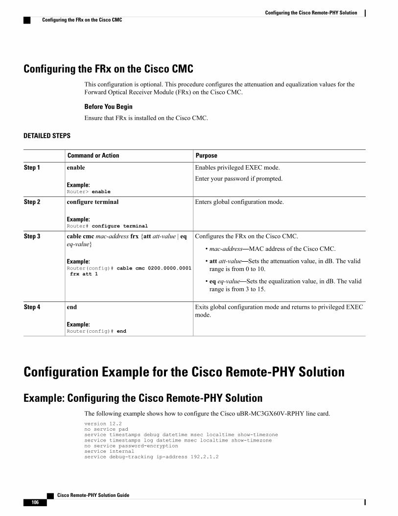
Configuring the FRx on the Cisco CMCThis configuration is optional. This procedure configures the attenuation and equalization values for theForward Optical Receiver Module (FRx) on the Cisco CMC.
Before You Begin
Ensure that FRx is installed on the Cisco CMC.
DETAILED STEPS
PurposeCommand or Action
Enables privileged EXEC mode.enableStep 1
Example:Router> enable
Enter your password if prompted.
Enters global configuration mode.configure terminal
Example:Router# configure terminal
Step 2
Configures the FRx on the Cisco CMC.cable cmc mac-address frx {att att-value | eqeq-value}
Step 3
• mac-address—MAC address of the Cisco CMC.
Example:Router(config)# cable cmc 0200.0000.0001frx att 1
• att att-value—Sets the attenuation value, in dB. The validrange is from 0 to 10.
• eq eq-value—Sets the equalization value, in dB. The validrange is from 3 to 15.
Exits global configuration mode and returns to privileged EXECmode.
end
Example:Router(config)# end
Step 4
Configuration Example for the Cisco Remote-PHY Solution
Example: Configuring the Cisco Remote-PHY SolutionThe following example shows how to configure the Cisco uBR-MC3GX60V-RPHY line card.version 12.2no service padservice timestamps debug datetime msec localtime show-timezoneservice timestamps log datetime msec localtime show-timezoneno service password-encryptionservice internalservice debug-tracking ip-address 192.2.1.2
Cisco Remote-PHY Solution Guide106
Configuring the Cisco Remote-PHY SolutionConfiguring the FRx on the Cisco CMC

!hostname App-10k-10!logging buffered 5000000no logging rate-limitno logging console!no aaa new-modelclock timezone CST 8facility-alarm outlet-temperature major 58facility-alarm outlet-temperature minor 48facility-alarm outlet-temperature critical 85facility-alarm intake-temperature major 51facility-alarm intake-temperature minor 41facility-alarm intake-temperature critical 73!card 1 4jacket-1card 1/0 SPA-1XTENGE-XFP-V2card 1/1 SPA-1XTENGE-XFP-V2card 1/1 2cable-dtcccard 7/1 ubr10k-clc-3g60-rphy license 72X60!!cable logging badipsourcecable logging layer2eventscable logging overlapipcable logging ironbuscable logging downstream-indexcable clock dti!ip subnet-zerono ip domain lookupip host rfsw-1 192.4.0.36ip host rfsw-2 192.4.0.36ip name-server 192.1.0.2ip multicast-routing!ip dhcp pool cmcnetwork 192.71.0.0 255.255.255.0next-server 192.71.0.1default-router 192.71.0.1lease 7 0 10!
controller Modular-Cable 7/1/0rf-channel 0 cable downstream channel-id 73rf-channel 0 frequency 451000000 annex A modulation 256qam interleave 12rf-channel 0 group-address 192.1.2.1no rf-channel 0 rf-shutdownrf-channel 1 cable downstream channel-id 74rf-channel 2 cable downstream channel-id 75rf-channel 3 cable downstream channel-id 76rf-channel 4 cable downstream channel-id 77rf-channel 5 cable downstream channel-id 78rf-channel 6 cable downstream channel-id 79rf-channel 7 cable downstream channel-id 80rf-channel 8 cable downstream channel-id 81rf-channel 9 cable downstream channel-id 82rf-channel 10 cable downstream channel-id 83rf-channel 11 cable downstream channel-id 84rf-channel 12 cable downstream channel-id 85rf-channel 13 cable downstream channel-id 86rf-channel 14 cable downstream channel-id 87rf-channel 15 cable downstream channel-id 88rf-channel 16 cable downstream channel-id 89rf-channel 17 cable downstream channel-id 90rf-channel 18 cable downstream channel-id 91rf-channel 19 cable downstream channel-id 92rf-channel 20 cable downstream channel-id 93rf-channel 21 cable downstream channel-id 94rf-channel 22 cable downstream channel-id 95rf-channel 23 cable downstream channel-id 96!
Cisco Remote-PHY Solution Guide 107
Configuring the Cisco Remote-PHY SolutionExample: Configuring the Cisco Remote-PHY Solution

controller Modular-Cable 7/1/1rf-channel 0 cable downstream channel-id 97rf-channel 1 cable downstream channel-id 98rf-channel 2 cable downstream channel-id 99rf-channel 3 cable downstream channel-id 100rf-channel 4 cable downstream channel-id 101rf-channel 5 cable downstream channel-id 102rf-channel 6 cable downstream channel-id 103rf-channel 7 cable downstream channel-id 104rf-channel 8 cable downstream channel-id 105rf-channel 9 cable downstream channel-id 106rf-channel 10 cable downstream channel-id 107rf-channel 11 cable downstream channel-id 108rf-channel 12 cable downstream channel-id 109rf-channel 13 cable downstream channel-id 110rf-channel 14 cable downstream channel-id 111rf-channel 15 cable downstream channel-id 112rf-channel 16 cable downstream channel-id 113rf-channel 17 cable downstream channel-id 114rf-channel 18 cable downstream channel-id 115rf-channel 19 cable downstream channel-id 116rf-channel 20 cable downstream channel-id 117rf-channel 21 cable downstream channel-id 118rf-channel 22 cable downstream channel-id 119rf-channel 23 cable downstream channel-id 120!controller Modular-Cable 7/1/2rf-channel 0 cable downstream channel-id 121rf-channel 1 cable downstream channel-id 122rf-channel 2 cable downstream channel-id 123rf-channel 3 cable downstream channel-id 124rf-channel 4 cable downstream channel-id 125rf-channel 5 cable downstream channel-id 126rf-channel 6 cable downstream channel-id 127rf-channel 7 cable downstream channel-id 128rf-channel 8 cable downstream channel-id 129rf-channel 9 cable downstream channel-id 130rf-channel 10 cable downstream channel-id 131rf-channel 11 cable downstream channel-id 132rf-channel 12 cable downstream channel-id 133rf-channel 13 cable downstream channel-id 134rf-channel 14 cable downstream channel-id 135rf-channel 15 cable downstream channel-id 136rf-channel 16 cable downstream channel-id 137rf-channel 17 cable downstream channel-id 138rf-channel 18 cable downstream channel-id 139rf-channel 19 cable downstream channel-id 140rf-channel 20 cable downstream channel-id 141rf-channel 21 cable downstream channel-id 142rf-channel 22 cable downstream channel-id 143rf-channel 23 cable downstream channel-id 144!!interface Loopback1no ip addressno ip route-cache cefno ip route-cacheip rsvp bandwidth 10000ip rsvp listener outbound reply!interface FastEthernet0/0/0ip address 192.4.0.37 255.255.255.0no ip route-cache cefno ip route-cachemedia-type rj45speed autoduplex autoipv6 address 2001:DB:4:1::37/64ipv6 enable!interface TenGigabitEthernet1/0/0no ip address!
Cisco Remote-PHY Solution Guide108
Configuring the Cisco Remote-PHY SolutionExample: Configuring the Cisco Remote-PHY Solution

interface TenGigabitEthernet1/1/0no ip address!!interface Cable7/1/0downstream Modular-Cable 7/1/0 rf-channel 0no cable mtc-modeno cable packet-cachecable bundle 1cable upstream max-ports 4cable upstream 0 connector 0cable upstream 0 frequency 20000000cable upstream 0 channel-width 6400000cable upstream 0 docsis-mode atdmacable upstream 0 minislot-size 4cable upstream 0 range-backoff 3 6cable upstream 0 modulation-profile 221no cable upstream 0 shutdowncable upstream 1 connector 0cable upstream 1 channel-width 1600000cable upstream 1 docsis-mode atdmacable upstream 1 minislot-size 4cable upstream 1 range-backoff 3 6cable upstream 1 modulation-profile 221cable upstream 1 shutdowncable upstream 2 connector 0cable upstream 2 channel-width 1600000cable upstream 2 docsis-mode atdmacable upstream 2 minislot-size 4cable upstream 2 range-backoff 3 6cable upstream 2 modulation-profile 221cable upstream 2 shutdowncable upstream 3 connector 0cable upstream 3 channel-width 1600000cable upstream 3 docsis-mode atdmacable upstream 3 minislot-size 4cable upstream 3 range-backoff 3 6cable upstream 3 modulation-profile 221cable upstream 3 shutdown!interface Cable7/1/1no cable packet-cachecable upstream max-ports 4cable upstream 0 connector 0cable upstream 0 channel-width 1600000cable upstream 0 docsis-mode atdmacable upstream 0 minislot-size 4cable upstream 0 range-backoff 3 6cable upstream 0 modulation-profile 221cable upstream 0 shutdowncable upstream 1 connector 0cable upstream 1 channel-width 1600000cable upstream 1 docsis-mode atdmacable upstream 1 minislot-size 4cable upstream 1 range-backoff 3 6cable upstream 1 modulation-profile 221cable upstream 1 shutdowncable upstream 2 connector 0cable upstream 2 channel-width 1600000cable upstream 2 docsis-mode atdmacable upstream 2 minislot-size 4cable upstream 2 range-backoff 3 6cable upstream 2 modulation-profile 221cable upstream 2 shutdowncable upstream 3 connector 0cable upstream 3 channel-width 1600000cable upstream 3 docsis-mode atdmacable upstream 3 minislot-size 4cable upstream 3 range-backoff 3 6cable upstream 3 modulation-profile 221cable upstream 3 shutdown!
Cisco Remote-PHY Solution Guide 109
Configuring the Cisco Remote-PHY SolutionExample: Configuring the Cisco Remote-PHY Solution

interface GigabitEthernet7/1/0ip address 192.71.0.1 255.255.255.0ip pim sparse-dense-modenegotiation auto!interface GigabitEthernet7/1/2no ip addressnegotiation auto!
interface Bundle1ip address 192.2.1.1 255.255.255.0ip pim sparse-modeip igmp version 3cable multicast-qos group 20cable arp filter request-send 3 2cable arp filter reply-accept 3 2cable dhcp-giaddr policycable helper-address 192.1.0.3ip rsvp bandwidth 10000ip rsvp listener outbound reply!ip default-gateway 192.4.0.1ip classless!no ip http serverno ip http secure-server!!logging cmts ipc-cable log-level errorslogging cmts sea syslog-level errorscpd cr-id 1nls resp-timeout 1cdp run!tftp-server disk0:basic.cm alias golden.cm!control-plane!alias exec ccmad clear cable modem all deletealias exec scm show cable modemalias exec ccm clear cable modemalias exec scc show cable cmc!line con 0exec-timeout 0 0privilege level 15stopbits 1line aux 0stopbits 1line vty 0 4exec-timeout 0 0privilege level 15no loginline vty 5 15privilege level 15no loginline vty 16 50no login!scheduler isr-watchdog!cable channel-group 71upstream Cable7/1/0 channel 0-3downstream Modular-Cable 7/1/0 rf-channel 0-7cmc 0200.0000.0001!ntp clock-period 17179828ntp update-calendarntp server 20.1.0.2end
Cisco Remote-PHY Solution Guide110
Configuring the Cisco Remote-PHY SolutionExample: Configuring the Cisco Remote-PHY Solution

Example: Configuring CMTS and Router in Layer 3 CIN NetworkThe following example shows how to configure CMTS in Layer 3 CIN network shown in the illustration ofConfiguring the Layer 3 CIN Network support, on page 102.issu-ubr10k-5#show runBuilding configuration...
Current configuration : 143626 bytes!! Last configuration change at 16:28:30 CST Tue Mar 24 2015!version 12.2no service padservice timestamps debug datetime msec localtime show-timezoneservice timestamps log datetime msec localtime show-timezoneno service password-encryptionservice internalservice udp-small-servers max-servers 25service debug-tracking ip-address 50.1.0.1service debug-tracking context-copy!hostname issu-ubr10k-5!boot-start-markerboot system disk0:ubr10k4-k9p6u2-mz.cd102.dbgboot-end-marker!logging buffered 20000000logging rate-limit console 10no logging consoleenable password lab!no aaa new-modelclock timezone CST 8facility-alarm outlet-temperature major 58facility-alarm outlet-temperature minor 48facility-alarm outlet-temperature critical 85no facility-alarm intake-temperature majorno facility-alarm intake-temperature minorfacility-alarm intake-temperature critical 72!!!!card 1 4jacket-1card 3 4jacket-1card 5/0 ubr10k-clc-3g60-rphy license 72X60card 6/0 ubr10k-clc-3g60 license 16X60card 7/1 ubr10k-clc-3g60-rphy license 72X60!cable admission-control preempt priority-voice!cable source-verify group ngspa-perf!!!cable modem v6-max-cpe-prefix 16cable service class 1 name mcast1cable service class 1 downstreamcable service class 11 name ugs_testcable service class 11 upstreamcable service class 11 sched-type 6cable service class 11 req-trans-policy 3FFcable service class 11 grant-size 232cable service class 11 grant-interval 20000cable service class 11 grant-jitter 10000cable service class 11 grants-per-interval 1cable service class 11 max-buff-size 200000000no cable qos permission createno cable qos permission update
Cisco Remote-PHY Solution Guide 111
Configuring the Cisco Remote-PHY SolutionExample: Configuring CMTS and Router in Layer 3 CIN Network

cable qos permission modems!cable logging badipsourcecable logging layer2eventscable logging overlapipcable logging ironbuscable logging downstream-indexcable time-servercable clock dticable cmc 9078.5634.1200 ds-rf-power 52.0 tilt -12dBcable privacy hotlist cm 7cb2.1b10.32d2cable privacy hotlist cm 7cb2.1b10.2248cable load-balance docsis-enable!cable load-balance docsis-group 1!cable load-balance docsis-group 2!cable load-balance group 1 method utilizationcable load-balance group 1 threshold load minimum 1cable load-balance group 79cable load-balance group 80!ip subnet-zerono ip domain lookupip host rfsw-1 20.5.0.50ip host rfsw-2 20.5.0.50ip multicast-routingip dhcp smart-relayno ip dhcp use vrf connectedip dhcp excluded-address 50.2.0.1!ip dhcp pool CMC-50
network 50.2.0.0 255.255.255.0bootfile tftp://50.1.0.1/cmc-16x4-os-20141127.bindefault-router 50.2.0.1lease 7 0 10
!!!!ipv6 multicast rpf use-bgpl2tp-class l2tp-class_6_0hello 5hostname lchc6_0retransmit retries 5retransmit timeout max 1!packetcable multimediadepi-class depi-class_6_0mode mpt!depi-tunnel 3g60_6_0_0dest-ip 192.60.0.2l2tp-class l2tp-class_6_0depi-class depi-class_6_0protect-tunnel 3g60_6_1_0_p!depi-tunnel 3g60_6_1_0_pdest-ip 192.61.0.2!!diagnostic bootup level minimal!redundancymode sso
!controller Modular-Cable 5/0/0rf-channel 0 cable downstream channel-id 1rf-channel 0 frequency 453000000 annex B modulation 256qam interleave 32rf-channel 0 group-address 225.1.1.2no rf-channel 0 rf-shutdownrf-channel 1 cable downstream channel-id 2
Cisco Remote-PHY Solution Guide112
Configuring the Cisco Remote-PHY SolutionExample: Configuring CMTS and Router in Layer 3 CIN Network

rf-channel 1 frequency 459000000 annex B modulation 256qam interleave 32rf-channel 1 group-address 225.1.1.2no rf-channel 1 rf-shutdownrf-channel 2 cable downstream channel-id 3rf-channel 2 frequency 465000000 annex B modulation 256qam interleave 32rf-channel 2 group-address 225.1.1.2no rf-channel 2 rf-shutdownrf-channel 3 cable downstream channel-id 4rf-channel 3 frequency 471000000 annex B modulation 256qam interleave 32rf-channel 3 group-address 225.1.1.2no rf-channel 3 rf-shutdownrf-channel 4 cable downstream channel-id 5rf-channel 4 frequency 477000000 annex B modulation 256qam interleave 32rf-channel 4 group-address 225.1.1.2no rf-channel 4 rf-shutdownrf-channel 5 cable downstream channel-id 6rf-channel 5 frequency 483000000 annex B modulation 256qam interleave 32rf-channel 5 group-address 225.1.1.2no rf-channel 5 rf-shutdownrf-channel 6 cable downstream channel-id 7rf-channel 6 frequency 489000000 annex B modulation 256qam interleave 32rf-channel 6 group-address 225.1.1.2no rf-channel 6 rf-shutdownrf-channel 7 cable downstream channel-id 8rf-channel 7 frequency 495000000 annex B modulation 256qam interleave 32rf-channel 7 group-address 225.1.1.2no rf-channel 7 rf-shutdownrf-channel 8 cable downstream channel-id 9rf-channel 9 cable downstream channel-id 10rf-channel 10 cable downstream channel-id 11rf-channel 11 cable downstream channel-id 12rf-channel 12 cable downstream channel-id 13rf-channel 13 cable downstream channel-id 14rf-channel 14 cable downstream channel-id 15rf-channel 15 cable downstream channel-id 16rf-channel 16 cable downstream channel-id 17rf-channel 17 cable downstream channel-id 18rf-channel 18 cable downstream channel-id 19rf-channel 19 cable downstream channel-id 20rf-channel 20 cable downstream channel-id 21rf-channel 21 cable downstream channel-id 22rf-channel 22 cable downstream channel-id 23rf-channel 23 cable downstream channel-id 24!controller Modular-Cable 5/0/1rf-channel 0 cable downstream channel-id 25rf-channel 1 cable downstream channel-id 26rf-channel 2 cable downstream channel-id 27rf-channel 3 cable downstream channel-id 28rf-channel 4 cable downstream channel-id 29rf-channel 5 cable downstream channel-id 30rf-channel 6 cable downstream channel-id 31rf-channel 7 cable downstream channel-id 32rf-channel 8 cable downstream channel-id 33rf-channel 9 cable downstream channel-id 34rf-channel 10 cable downstream channel-id 35rf-channel 11 cable downstream channel-id 36rf-channel 12 cable downstream channel-id 37rf-channel 13 cable downstream channel-id 38rf-channel 14 cable downstream channel-id 39rf-channel 15 cable downstream channel-id 40rf-channel 16 cable downstream channel-id 41rf-channel 17 cable downstream channel-id 42rf-channel 18 cable downstream channel-id 43rf-channel 19 cable downstream channel-id 44rf-channel 20 cable downstream channel-id 45rf-channel 21 cable downstream channel-id 46rf-channel 22 cable downstream channel-id 47rf-channel 23 cable downstream channel-id 48!controller Modular-Cable 5/0/2rf-channel 0 cable downstream channel-id 1rf-channel 0 frequency 453000000 annex B modulation 256qam interleave 32
Cisco Remote-PHY Solution Guide 113
Configuring the Cisco Remote-PHY SolutionExample: Configuring CMTS and Router in Layer 3 CIN Network

rf-channel 0 group-address 225.1.1.2no rf-channel 0 rf-shutdownrf-channel 1 cable downstream channel-id 2rf-channel 1 frequency 459000000 annex B modulation 256qam interleave 32rf-channel 1 group-address 225.1.1.2no rf-channel 1 rf-shutdownrf-channel 2 cable downstream channel-id 3rf-channel 2 frequency 465000000 annex B modulation 256qam interleave 32rf-channel 2 group-address 225.1.1.2no rf-channel 2 rf-shutdownrf-channel 3 cable downstream channel-id 4rf-channel 3 frequency 471000000 annex B modulation 256qam interleave 32rf-channel 3 group-address 225.1.1.2no rf-channel 3 rf-shutdownrf-channel 4 cable downstream channel-id 5rf-channel 4 frequency 477000000 annex B modulation 256qam interleave 32rf-channel 4 group-address 225.1.1.2no rf-channel 4 rf-shutdownrf-channel 5 cable downstream channel-id 6rf-channel 5 frequency 483000000 annex B modulation 256qam interleave 32rf-channel 5 group-address 225.1.1.2no rf-channel 5 rf-shutdownrf-channel 6 cable downstream channel-id 7rf-channel 6 frequency 489000000 annex B modulation 256qam interleave 32rf-channel 6 group-address 225.1.1.2no rf-channel 6 rf-shutdownrf-channel 7 cable downstream channel-id 8rf-channel 7 frequency 495000000 annex B modulation 256qam interleave 32rf-channel 7 group-address 225.1.1.2no rf-channel 7 rf-shutdownrf-channel 8 cable downstream channel-id 57rf-channel 9 cable downstream channel-id 58rf-channel 10 cable downstream channel-id 59rf-channel 11 cable downstream channel-id 60rf-channel 12 cable downstream channel-id 61rf-channel 13 cable downstream channel-id 62rf-channel 14 cable downstream channel-id 63rf-channel 15 cable downstream channel-id 64rf-channel 16 cable downstream channel-id 65rf-channel 17 cable downstream channel-id 66rf-channel 18 cable downstream channel-id 67rf-channel 19 cable downstream channel-id 68rf-channel 20 cable downstream channel-id 69rf-channel 21 cable downstream channel-id 70rf-channel 22 cable downstream channel-id 71rf-channel 23 cable downstream channel-id 72!controller Modular-Cable 6/0/0rf-channel 0 cable downstream channel-id 1rf-channel 0 frequency 483000000 annex B modulation 256qam interleave 128rf-channel 0 depi-tunnel 3g60_6_0_0 tsid 5091no rf-channel 0 rf-shutdownrf-channel 1 cable downstream channel-id 2rf-channel 1 frequency 489000000 annex B modulation 256qam interleave 128rf-channel 1 depi-tunnel 3g60_6_0_0 tsid 5092no rf-channel 1 rf-shutdownrf-channel 2 cable downstream channel-id 3rf-channel 2 frequency 495000000 annex B modulation 256qam interleave 128rf-channel 2 depi-tunnel 3g60_6_0_0 tsid 5093no rf-channel 2 rf-shutdownrf-channel 3 cable downstream channel-id 4rf-channel 3 frequency 501000000 annex B modulation 256qam interleave 128rf-channel 3 depi-tunnel 3g60_6_0_0 tsid 5094rf-channel 3 rf-shutdownrf-channel 4 cable downstream channel-id 5rf-channel 4 frequency 507000000 annex B modulation 256qam interleave 128rf-channel 4 depi-tunnel 3g60_6_0_0 tsid 5095no rf-channel 4 rf-shutdownrf-channel 5 cable downstream channel-id 6rf-channel 5 frequency 146000000 annex B modulation 256qam interleave 128rf-channel 5 depi-tunnel 3g60_6_0_0 tsid 5096no rf-channel 5 rf-shutdownrf-channel 6 cable downstream channel-id 7
Cisco Remote-PHY Solution Guide114
Configuring the Cisco Remote-PHY SolutionExample: Configuring CMTS and Router in Layer 3 CIN Network
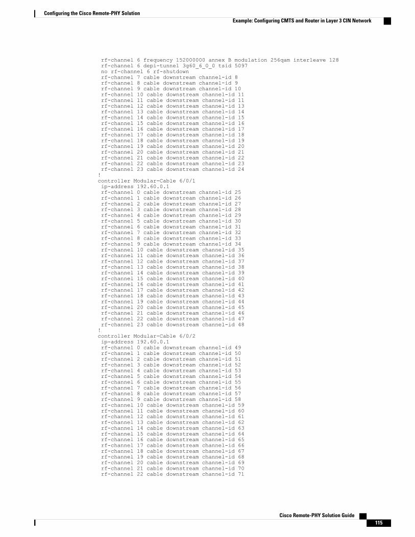
rf-channel 6 frequency 152000000 annex B modulation 256qam interleave 128rf-channel 6 depi-tunnel 3g60_6_0_0 tsid 5097no rf-channel 6 rf-shutdownrf-channel 7 cable downstream channel-id 8rf-channel 8 cable downstream channel-id 9rf-channel 9 cable downstream channel-id 10rf-channel 10 cable downstream channel-id 11rf-channel 11 cable downstream channel-id 11rf-channel 12 cable downstream channel-id 13rf-channel 13 cable downstream channel-id 14rf-channel 14 cable downstream channel-id 15rf-channel 15 cable downstream channel-id 16rf-channel 16 cable downstream channel-id 17rf-channel 17 cable downstream channel-id 18rf-channel 18 cable downstream channel-id 19rf-channel 19 cable downstream channel-id 20rf-channel 20 cable downstream channel-id 21rf-channel 21 cable downstream channel-id 22rf-channel 22 cable downstream channel-id 23rf-channel 23 cable downstream channel-id 24!controller Modular-Cable 6/0/1ip-address 192.60.0.1rf-channel 0 cable downstream channel-id 25rf-channel 1 cable downstream channel-id 26rf-channel 2 cable downstream channel-id 27rf-channel 3 cable downstream channel-id 28rf-channel 4 cable downstream channel-id 29rf-channel 5 cable downstream channel-id 30rf-channel 6 cable downstream channel-id 31rf-channel 7 cable downstream channel-id 32rf-channel 8 cable downstream channel-id 33rf-channel 9 cable downstream channel-id 34rf-channel 10 cable downstream channel-id 35rf-channel 11 cable downstream channel-id 36rf-channel 12 cable downstream channel-id 37rf-channel 13 cable downstream channel-id 38rf-channel 14 cable downstream channel-id 39rf-channel 15 cable downstream channel-id 40rf-channel 16 cable downstream channel-id 41rf-channel 17 cable downstream channel-id 42rf-channel 18 cable downstream channel-id 43rf-channel 19 cable downstream channel-id 44rf-channel 20 cable downstream channel-id 45rf-channel 21 cable downstream channel-id 46rf-channel 22 cable downstream channel-id 47rf-channel 23 cable downstream channel-id 48!controller Modular-Cable 6/0/2ip-address 192.60.0.1rf-channel 0 cable downstream channel-id 49rf-channel 1 cable downstream channel-id 50rf-channel 2 cable downstream channel-id 51rf-channel 3 cable downstream channel-id 52rf-channel 4 cable downstream channel-id 53rf-channel 5 cable downstream channel-id 54rf-channel 6 cable downstream channel-id 55rf-channel 7 cable downstream channel-id 56rf-channel 8 cable downstream channel-id 57rf-channel 9 cable downstream channel-id 58rf-channel 10 cable downstream channel-id 59rf-channel 11 cable downstream channel-id 60rf-channel 12 cable downstream channel-id 61rf-channel 13 cable downstream channel-id 62rf-channel 14 cable downstream channel-id 63rf-channel 15 cable downstream channel-id 64rf-channel 16 cable downstream channel-id 65rf-channel 17 cable downstream channel-id 66rf-channel 18 cable downstream channel-id 67rf-channel 19 cable downstream channel-id 68rf-channel 20 cable downstream channel-id 69rf-channel 21 cable downstream channel-id 70rf-channel 22 cable downstream channel-id 71
Cisco Remote-PHY Solution Guide 115
Configuring the Cisco Remote-PHY SolutionExample: Configuring CMTS and Router in Layer 3 CIN Network

rf-channel 23 cable downstream channel-id 72!!!!!!interface FastEthernet0/0/0ip address 80.1.1.51 255.255.255.0no ip proxy-arpno ip route-cache cefno ip route-cachemedia-type rj45speed 100duplex auto!interface Cable5/0/0downstream Modular-Cable 5/0/0 rf-channel 0-7 upstream 0-3cable mtc-modeno cable packet-cachecable default-phy-burst 0cable bundle 4cable upstream max-ports 4cable upstream bonding-group 1upstream 0upstream 1upstream 2upstream 3attributes 80000000cable upstream 0 connector 0cable upstream 0 frequency 20000000cable upstream 0 channel-width 6400000cable upstream 0 docsis-mode atdmacable upstream 0 minislot-size 4cable upstream 0 range-backoff 3 6cable upstream 0 modulation-profile 221no cable upstream 0 rate-limitcable upstream 0 rate-adaptno cable upstream 0 shutdowncable upstream 1 connector 0cable upstream 1 frequency 28000000cable upstream 1 channel-width 6400000cable upstream 1 docsis-mode atdmacable upstream 1 minislot-size 4cable upstream 1 range-backoff 3 6cable upstream 1 modulation-profile 221no cable upstream 1 rate-limitcable upstream 1 rate-adaptno cable upstream 1 shutdowncable upstream 2 connector 0cable upstream 2 frequency 36000000cable upstream 2 channel-width 6400000cable upstream 2 docsis-mode atdmacable upstream 2 minislot-size 4cable upstream 2 range-backoff 3 6cable upstream 2 modulation-profile 221no cable upstream 2 rate-limitcable upstream 2 rate-adaptno cable upstream 2 shutdowncable upstream 3 connector 0cable upstream 3 frequency 44000000cable upstream 3 channel-width 6400000cable upstream 3 docsis-mode atdmacable upstream 3 minislot-size 4cable upstream 3 range-backoff 3 6cable upstream 3 modulation-profile 221no cable upstream 3 rate-limitcable upstream 3 rate-adaptno cable upstream 3 shutdown!interface Cable5/0/1no cable packet-cachecable upstream max-ports 4
Cisco Remote-PHY Solution Guide116
Configuring the Cisco Remote-PHY SolutionExample: Configuring CMTS and Router in Layer 3 CIN Network

cable upstream 0 connector 0cable upstream 0 channel-width 1600000cable upstream 0 docsis-mode atdmacable upstream 0 minislot-size 4cable upstream 0 range-backoff 3 6cable upstream 0 modulation-profile 221cable upstream 0 shutdowncable upstream 1 connector 0cable upstream 1 channel-width 1600000cable upstream 1 docsis-mode atdmacable upstream 1 minislot-size 4cable upstream 1 range-backoff 3 6cable upstream 1 modulation-profile 221cable upstream 1 shutdowncable upstream 2 connector 1cable upstream 2 channel-width 1600000cable upstream 2 docsis-mode atdmacable upstream 2 minislot-size 4cable upstream 2 range-backoff 3 6cable upstream 2 modulation-profile 221cable upstream 2 shutdowncable upstream 3 connector 0cable upstream 3 channel-width 1600000cable upstream 3 docsis-mode atdmacable upstream 3 minislot-size 4cable upstream 3 range-backoff 3 6cable upstream 3 modulation-profile 221cable upstream 3 shutdown!interface Cable5/0/2no cable packet-cachecable upstream max-ports 4cable upstream 0 connector 0cable upstream 0 channel-width 1600000cable upstream 0 docsis-mode atdmacable upstream 0 minislot-size 4cable upstream 0 range-backoff 3 6cable upstream 0 modulation-profile 221cable upstream 0 shutdowncable upstream 1 connector 0cable upstream 1 channel-width 1600000cable upstream 1 docsis-mode atdmacable upstream 1 minislot-size 4cable upstream 1 range-backoff 3 6cable upstream 1 modulation-profile 221cable upstream 1 shutdowncable upstream 2 connector 0cable upstream 2 channel-width 1600000cable upstream 2 docsis-mode atdmacable upstream 2 minislot-size 4cable upstream 2 range-backoff 3 6cable upstream 2 modulation-profile 221cable upstream 2 shutdowncable upstream 3 connector 0cable upstream 3 channel-width 1600000cable upstream 3 docsis-mode atdmacable upstream 3 minislot-size 4cable upstream 3 range-backoff 3 6cable upstream 3 modulation-profile 221cable upstream 3 shutdown!interface Cable5/0/3no cable packet-cachecable upstream max-ports 4cable upstream 0 connector 0cable upstream 0 channel-width 1600000cable upstream 0 docsis-mode atdmacable upstream 0 minislot-size 4cable upstream 0 range-backoff 3 6cable upstream 0 modulation-profile 221cable upstream 0 shutdowncable upstream 1 connector 0cable upstream 1 channel-width 1600000
Cisco Remote-PHY Solution Guide 117
Configuring the Cisco Remote-PHY SolutionExample: Configuring CMTS and Router in Layer 3 CIN Network

cable upstream 1 docsis-mode atdmacable upstream 1 minislot-size 4cable upstream 1 range-backoff 3 6cable upstream 1 modulation-profile 221cable upstream 1 shutdowncable upstream 2 connector 0cable upstream 2 channel-width 1600000cable upstream 2 docsis-mode atdmacable upstream 2 minislot-size 4cable upstream 2 range-backoff 3 6cable upstream 2 modulation-profile 221cable upstream 2 shutdowncable upstream 3 connector 0cable upstream 3 channel-width 1600000cable upstream 3 docsis-mode atdmacable upstream 3 minislot-size 4cable upstream 3 range-backoff 3 6cable upstream 3 modulation-profile 221cable upstream 3 shutdown!interface Cable5/0/4no cable packet-cachecable upstream max-ports 4cable upstream 0 connector 0cable upstream 0 channel-width 1600000cable upstream 0 docsis-mode atdmacable upstream 0 minislot-size 4cable upstream 0 range-backoff 3 6cable upstream 0 modulation-profile 221cable upstream 0 shutdowncable upstream 1 connector 0cable upstream 1 channel-width 1600000cable upstream 1 docsis-mode atdmacable upstream 1 minislot-size 4cable upstream 1 range-backoff 3 6cable upstream 1 modulation-profile 221cable upstream 1 shutdowncable upstream 2 connector 0cable upstream 2 channel-width 1600000cable upstream 2 docsis-mode atdmacable upstream 2 minislot-size 4cable upstream 2 range-backoff 3 6cable upstream 2 modulation-profile 221cable upstream 2 shutdowncable upstream 3 connector 0cable upstream 3 channel-width 1600000cable upstream 3 docsis-mode atdmacable upstream 3 minislot-size 4cable upstream 3 range-backoff 3 6cable upstream 3 modulation-profile 221cable upstream 3 shutdown!interface Cable5/0/5no cable packet-cachecable upstream max-ports 4no cable upstream 0 connectorcable upstream 0 channel-width 1600000cable upstream 0 docsis-mode atdmacable upstream 0 minislot-size 4cable upstream 0 range-backoff 3 6cable upstream 0 modulation-profile 221cable upstream 0 shutdownno cable upstream 1 connectorcable upstream 1 channel-width 1600000cable upstream 1 docsis-mode atdmacable upstream 1 minislot-size 4cable upstream 1 range-backoff 3 6cable upstream 1 modulation-profile 221cable upstream 1 shutdowncable upstream 2 connector 1cable upstream 2 channel-width 1600000cable upstream 2 docsis-mode atdmacable upstream 2 minislot-size 4
Cisco Remote-PHY Solution Guide118
Configuring the Cisco Remote-PHY SolutionExample: Configuring CMTS and Router in Layer 3 CIN Network

cable upstream 2 range-backoff 3 6cable upstream 2 modulation-profile 221cable upstream 2 shutdowncable upstream 3 connector 1cable upstream 3 channel-width 1600000cable upstream 3 docsis-mode atdmacable upstream 3 minislot-size 4cable upstream 3 range-backoff 3 6cable upstream 3 modulation-profile 221cable upstream 3 shutdown!interface Cable5/0/6no cable packet-cachecable upstream max-ports 4cable upstream 0 connector 1cable upstream 0 channel-width 1600000cable upstream 0 docsis-mode atdmacable upstream 0 minislot-size 4cable upstream 0 range-backoff 3 6cable upstream 0 modulation-profile 221cable upstream 0 shutdowncable upstream 1 connector 1cable upstream 1 channel-width 1600000cable upstream 1 docsis-mode atdmacable upstream 1 minislot-size 4cable upstream 1 range-backoff 3 6cable upstream 1 modulation-profile 221cable upstream 1 shutdowncable upstream 2 connector 1cable upstream 2 channel-width 1600000cable upstream 2 docsis-mode atdmacable upstream 2 minislot-size 4cable upstream 2 range-backoff 3 6cable upstream 2 modulation-profile 221cable upstream 2 shutdowncable upstream 3 connector 1cable upstream 3 channel-width 1600000cable upstream 3 docsis-mode atdmacable upstream 3 minislot-size 4cable upstream 3 range-backoff 3 6cable upstream 3 modulation-profile 221cable upstream 3 shutdown!interface Cable5/0/7no cable packet-cachecable upstream max-ports 4cable upstream 0 connector 1cable upstream 0 channel-width 1600000cable upstream 0 docsis-mode atdmacable upstream 0 minislot-size 4cable upstream 0 range-backoff 3 6cable upstream 0 modulation-profile 221cable upstream 0 shutdowncable upstream 1 connector 1cable upstream 1 channel-width 1600000cable upstream 1 docsis-mode atdmacable upstream 1 minislot-size 4cable upstream 1 range-backoff 3 6cable upstream 1 modulation-profile 221cable upstream 1 shutdowncable upstream 2 connector 1cable upstream 2 channel-width 1600000cable upstream 2 docsis-mode atdmacable upstream 2 minislot-size 4cable upstream 2 range-backoff 3 6cable upstream 2 modulation-profile 221cable upstream 2 shutdowncable upstream 3 connector 1cable upstream 3 channel-width 1600000cable upstream 3 docsis-mode atdmacable upstream 3 minislot-size 4cable upstream 3 range-backoff 3 6cable upstream 3 modulation-profile 221
Cisco Remote-PHY Solution Guide 119
Configuring the Cisco Remote-PHY SolutionExample: Configuring CMTS and Router in Layer 3 CIN Network

cable upstream 3 shutdown!interface Cable5/0/8no cable packet-cachecable upstream max-ports 4cable upstream 0 connector 1cable upstream 0 channel-width 1600000cable upstream 0 docsis-mode atdmacable upstream 0 minislot-size 4cable upstream 0 range-backoff 3 6cable upstream 0 modulation-profile 221cable upstream 0 shutdowncable upstream 1 connector 1cable upstream 1 channel-width 1600000cable upstream 1 docsis-mode atdmacable upstream 1 minislot-size 4cable upstream 1 range-backoff 3 6cable upstream 1 modulation-profile 221cable upstream 1 shutdowncable upstream 2 connector 1cable upstream 2 channel-width 1600000cable upstream 2 docsis-mode atdmacable upstream 2 minislot-size 4cable upstream 2 range-backoff 3 6cable upstream 2 modulation-profile 221cable upstream 2 shutdowncable upstream 3 connector 1cable upstream 3 channel-width 1600000cable upstream 3 docsis-mode atdmacable upstream 3 minislot-size 4cable upstream 3 range-backoff 3 6cable upstream 3 modulation-profile 221cable upstream 3 shutdown!interface Cable5/0/9no cable packet-cachecable upstream max-ports 4cable upstream 0 connector 1cable upstream 0 channel-width 1600000cable upstream 0 docsis-mode atdmacable upstream 0 minislot-size 4cable upstream 0 range-backoff 3 6cable upstream 0 modulation-profile 221cable upstream 0 shutdowncable upstream 1 connector 1cable upstream 1 channel-width 1600000cable upstream 1 docsis-mode atdmacable upstream 1 minislot-size 4cable upstream 1 range-backoff 3 6cable upstream 1 modulation-profile 221cable upstream 1 shutdowncable upstream 2 connector 1cable upstream 2 channel-width 1600000cable upstream 2 docsis-mode atdmacable upstream 2 minislot-size 4cable upstream 2 range-backoff 3 6cable upstream 2 modulation-profile 221cable upstream 2 shutdowncable upstream 3 connector 1cable upstream 3 channel-width 1600000cable upstream 3 docsis-mode atdmacable upstream 3 minislot-size 4cable upstream 3 range-backoff 3 6cable upstream 3 modulation-profile 221cable upstream 3 shutdown!interface Cable5/0/10no cable packet-cachecable upstream max-ports 4cable upstream 0 connector 2cable upstream 0 channel-width 1600000cable upstream 0 docsis-mode atdmacable upstream 0 minislot-size 4
Cisco Remote-PHY Solution Guide120
Configuring the Cisco Remote-PHY SolutionExample: Configuring CMTS and Router in Layer 3 CIN Network
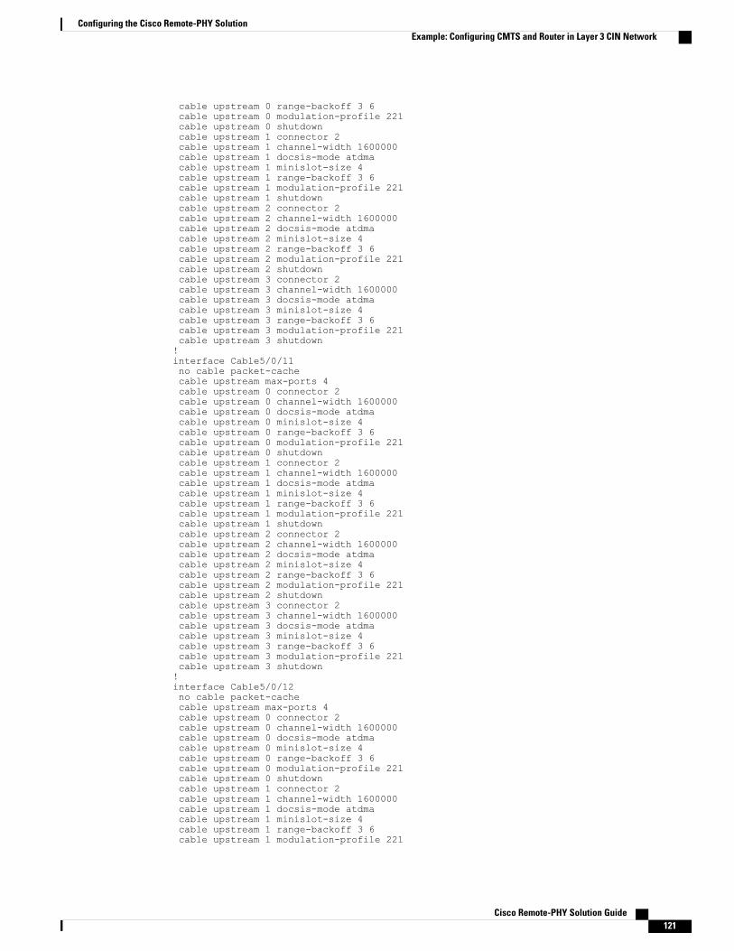
cable upstream 0 range-backoff 3 6cable upstream 0 modulation-profile 221cable upstream 0 shutdowncable upstream 1 connector 2cable upstream 1 channel-width 1600000cable upstream 1 docsis-mode atdmacable upstream 1 minislot-size 4cable upstream 1 range-backoff 3 6cable upstream 1 modulation-profile 221cable upstream 1 shutdowncable upstream 2 connector 2cable upstream 2 channel-width 1600000cable upstream 2 docsis-mode atdmacable upstream 2 minislot-size 4cable upstream 2 range-backoff 3 6cable upstream 2 modulation-profile 221cable upstream 2 shutdowncable upstream 3 connector 2cable upstream 3 channel-width 1600000cable upstream 3 docsis-mode atdmacable upstream 3 minislot-size 4cable upstream 3 range-backoff 3 6cable upstream 3 modulation-profile 221cable upstream 3 shutdown!interface Cable5/0/11no cable packet-cachecable upstream max-ports 4cable upstream 0 connector 2cable upstream 0 channel-width 1600000cable upstream 0 docsis-mode atdmacable upstream 0 minislot-size 4cable upstream 0 range-backoff 3 6cable upstream 0 modulation-profile 221cable upstream 0 shutdowncable upstream 1 connector 2cable upstream 1 channel-width 1600000cable upstream 1 docsis-mode atdmacable upstream 1 minislot-size 4cable upstream 1 range-backoff 3 6cable upstream 1 modulation-profile 221cable upstream 1 shutdowncable upstream 2 connector 2cable upstream 2 channel-width 1600000cable upstream 2 docsis-mode atdmacable upstream 2 minislot-size 4cable upstream 2 range-backoff 3 6cable upstream 2 modulation-profile 221cable upstream 2 shutdowncable upstream 3 connector 2cable upstream 3 channel-width 1600000cable upstream 3 docsis-mode atdmacable upstream 3 minislot-size 4cable upstream 3 range-backoff 3 6cable upstream 3 modulation-profile 221cable upstream 3 shutdown!interface Cable5/0/12no cable packet-cachecable upstream max-ports 4cable upstream 0 connector 2cable upstream 0 channel-width 1600000cable upstream 0 docsis-mode atdmacable upstream 0 minislot-size 4cable upstream 0 range-backoff 3 6cable upstream 0 modulation-profile 221cable upstream 0 shutdowncable upstream 1 connector 2cable upstream 1 channel-width 1600000cable upstream 1 docsis-mode atdmacable upstream 1 minislot-size 4cable upstream 1 range-backoff 3 6cable upstream 1 modulation-profile 221
Cisco Remote-PHY Solution Guide 121
Configuring the Cisco Remote-PHY SolutionExample: Configuring CMTS and Router in Layer 3 CIN Network

cable upstream 1 shutdowncable upstream 2 connector 2cable upstream 2 channel-width 1600000cable upstream 2 docsis-mode atdmacable upstream 2 minislot-size 4cable upstream 2 range-backoff 3 6cable upstream 2 modulation-profile 221cable upstream 2 shutdowncable upstream 3 connector 2cable upstream 3 channel-width 1600000cable upstream 3 docsis-mode atdmacable upstream 3 minislot-size 4cable upstream 3 range-backoff 3 6cable upstream 3 modulation-profile 221cable upstream 3 shutdown!interface Cable5/0/13no cable packet-cachecable upstream max-ports 4cable upstream 0 connector 2cable upstream 0 channel-width 1600000cable upstream 0 docsis-mode atdmacable upstream 0 minislot-size 4cable upstream 0 range-backoff 3 6cable upstream 0 modulation-profile 221cable upstream 0 shutdowncable upstream 1 connector 2cable upstream 1 channel-width 1600000cable upstream 1 docsis-mode atdmacable upstream 1 minislot-size 4cable upstream 1 range-backoff 3 6cable upstream 1 modulation-profile 221cable upstream 1 shutdowncable upstream 2 connector 2cable upstream 2 channel-width 1600000cable upstream 2 docsis-mode atdmacable upstream 2 minislot-size 4cable upstream 2 range-backoff 3 6cable upstream 2 modulation-profile 221cable upstream 2 shutdowncable upstream 3 connector 2cable upstream 3 channel-width 1600000cable upstream 3 docsis-mode atdmacable upstream 3 minislot-size 4cable upstream 3 range-backoff 3 6cable upstream 3 modulation-profile 221cable upstream 3 shutdown!interface Cable5/0/14no cable packet-cachecable upstream max-ports 4cable upstream 0 connector 2cable upstream 0 channel-width 1600000cable upstream 0 docsis-mode atdmacable upstream 0 minislot-size 4cable upstream 0 range-backoff 3 6cable upstream 0 modulation-profile 221cable upstream 0 shutdowncable upstream 1 connector 2cable upstream 1 channel-width 1600000cable upstream 1 docsis-mode atdmacable upstream 1 minislot-size 4cable upstream 1 range-backoff 3 6cable upstream 1 modulation-profile 221cable upstream 1 shutdowncable upstream 2 connector 2cable upstream 2 channel-width 1600000cable upstream 2 docsis-mode atdmacable upstream 2 minislot-size 4cable upstream 2 range-backoff 3 6cable upstream 2 modulation-profile 221cable upstream 2 shutdowncable upstream 3 connector 2
Cisco Remote-PHY Solution Guide122
Configuring the Cisco Remote-PHY SolutionExample: Configuring CMTS and Router in Layer 3 CIN Network

cable upstream 3 channel-width 1600000cable upstream 3 docsis-mode atdmacable upstream 3 minislot-size 4cable upstream 3 range-backoff 3 6cable upstream 3 modulation-profile 221cable upstream 3 shutdown!interface GigabitEthernet5/0/0mac-address 7081.052d.2438ip address 50.1.0.1 255.255.255.0ip access-group cmc-l3connect outip helper-address 20.1.0.33ip pim sparse-dense-modeip igmp version 3load-interval 30negotiation auto!interface GigabitEthernet5/0/2no ip addressnegotiation auto!interface GigabitEthernet5/0/4no ip addressnegotiation auto!interface Modular-Cable5/0/0:0cable bundle 4cable rf-bandwidth-percent 50!interface Modular-Cable5/0/0:1cable bundle 4cable rf-bandwidth-percent 50!interface Modular-Cable5/0/0:2cable bundle 4cable rf-bandwidth-percent 50!interface Modular-Cable5/0/0:3cable bundle 4cable rf-bandwidth-percent 50!interface Modular-Cable5/0/0:4cable bundle 4cable rf-bandwidth-percent 50!interface Modular-Cable5/0/0:5cable bundle 4cable rf-bandwidth-percent 50!interface Modular-Cable5/0/0:6cable bundle 4cable rf-bandwidth-percent 50!interface Modular-Cable5/0/0:7cable bundle 4cable rf-bandwidth-percent 50!interface Wideband-Cable5/0/0:0cable bundle 4cable rf-channel 0 bandwidth-percent 20cable rf-channel 1 bandwidth-percent 20cable rf-channel 2 bandwidth-percent 20cable rf-channel 3 bandwidth-percent 20cable rf-channel 4 bandwidth-percent 20cable rf-channel 5 bandwidth-percent 20cable rf-channel 6 bandwidth-percent 20cable rf-channel 7 bandwidth-percent 20!interface Cable6/0/0downstream Modular-Cable 6/0/0 rf-channel 0-6 upstream 0-3cable mtc-modeno cable packet-cachecable bundle 1
Cisco Remote-PHY Solution Guide 123
Configuring the Cisco Remote-PHY SolutionExample: Configuring CMTS and Router in Layer 3 CIN Network

cable upstream max-ports 4cable upstream bonding-group 1upstream 0upstream 1upstream 2upstream 3attributes A0000000cable upstream 0 connector 0cable upstream 0 frequency 20000000cable upstream 0 channel-width 1600000 1600000cable upstream 0 docsis-mode atdmacable upstream 0 minislot-size 4cable upstream 0 range-backoff 3 6cable upstream 0 modulation-profile 221cable upstream 0 attribute-mask 20000000no cable upstream 0 shutdowncable upstream 1 connector 1cable upstream 1 frequency 28000000cable upstream 1 channel-width 1600000 1600000cable upstream 1 docsis-mode atdmacable upstream 1 minislot-size 4cable upstream 1 range-backoff 3 6cable upstream 1 modulation-profile 221cable upstream 1 attribute-mask 20000000no cable upstream 1 shutdowncable upstream 2 connector 2cable upstream 2 frequency 36000000cable upstream 2 channel-width 1600000 1600000cable upstream 2 docsis-mode atdmacable upstream 2 minislot-size 4cable upstream 2 range-backoff 3 6cable upstream 2 modulation-profile 221cable upstream 2 attribute-mask 20000000no cable upstream 2 shutdowncable upstream 3 connector 3cable upstream 3 frequency 44000000cable upstream 3 channel-width 1600000 1600000cable upstream 3 docsis-mode atdmacable upstream 3 minislot-size 4cable upstream 3 range-backoff 3 6cable upstream 3 modulation-profile 221cable upstream 3 attribute-mask 20000000no cable upstream 3 shutdown!interface Cable6/0/1no cable packet-cachecable upstream max-ports 4no cable upstream 0 connectorcable upstream 0 channel-width 1600000 1600000cable upstream 0 docsis-mode atdmacable upstream 0 minislot-size 4cable upstream 0 range-backoff 3 6cable upstream 0 modulation-profile 221cable upstream 0 attribute-mask 20000000cable upstream 0 shutdownno cable upstream 1 connectorcable upstream 1 channel-width 1600000 1600000cable upstream 1 docsis-mode atdmacable upstream 1 minislot-size 4cable upstream 1 range-backoff 3 6cable upstream 1 modulation-profile 221cable upstream 1 attribute-mask 20000000cable upstream 1 shutdownno cable upstream 2 connectorcable upstream 2 channel-width 1600000 1600000cable upstream 2 docsis-mode atdmacable upstream 2 minislot-size 4cable upstream 2 range-backoff 3 6cable upstream 2 modulation-profile 221cable upstream 2 attribute-mask 20000000cable upstream 2 shutdownno cable upstream 3 connectorcable upstream 3 channel-width 1600000 1600000
Cisco Remote-PHY Solution Guide124
Configuring the Cisco Remote-PHY SolutionExample: Configuring CMTS and Router in Layer 3 CIN Network

cable upstream 3 docsis-mode atdmacable upstream 3 minislot-size 4cable upstream 3 range-backoff 3 6cable upstream 3 modulation-profile 221cable upstream 3 attribute-mask 20000000cable upstream 3 shutdown!interface Cable6/0/2no cable packet-cachecable upstream max-ports 4no cable upstream 0 connectorcable upstream 0 channel-width 1600000 1600000cable upstream 0 docsis-mode atdmacable upstream 0 minislot-size 4cable upstream 0 range-backoff 3 6cable upstream 0 modulation-profile 221cable upstream 0 attribute-mask 20000000cable upstream 0 shutdownno cable upstream 1 connectorcable upstream 1 channel-width 1600000 1600000cable upstream 1 docsis-mode atdmacable upstream 1 minislot-size 4cable upstream 1 range-backoff 3 6cable upstream 1 modulation-profile 221cable upstream 1 attribute-mask 20000000cable upstream 1 shutdownno cable upstream 2 connectorcable upstream 2 channel-width 1600000 1600000cable upstream 2 docsis-mode atdmacable upstream 2 minislot-size 4cable upstream 2 range-backoff 3 6cable upstream 2 modulation-profile 221cable upstream 2 attribute-mask 20000000cable upstream 2 shutdownno cable upstream 3 connectorcable upstream 3 channel-width 1600000 1600000cable upstream 3 docsis-mode atdmacable upstream 3 minislot-size 4cable upstream 3 range-backoff 3 6cable upstream 3 modulation-profile 221cable upstream 3 attribute-mask 20000000cable upstream 3 shutdown!interface Cable6/0/3no cable packet-cachecable upstream max-ports 4no cable upstream 0 connectorcable upstream 0 channel-width 1600000 1600000cable upstream 0 docsis-mode atdmacable upstream 0 minislot-size 4cable upstream 0 range-backoff 3 6cable upstream 0 modulation-profile 221cable upstream 0 attribute-mask 20000000cable upstream 0 shutdownno cable upstream 1 connectorcable upstream 1 channel-width 1600000 1600000cable upstream 1 docsis-mode atdmacable upstream 1 minislot-size 4cable upstream 1 range-backoff 3 6cable upstream 1 modulation-profile 221cable upstream 1 attribute-mask 20000000cable upstream 1 shutdownno cable upstream 2 connectorcable upstream 2 channel-width 1600000 1600000cable upstream 2 docsis-mode atdmacable upstream 2 minislot-size 4cable upstream 2 range-backoff 3 6cable upstream 2 modulation-profile 221cable upstream 2 attribute-mask 20000000cable upstream 2 shutdownno cable upstream 3 connectorcable upstream 3 channel-width 1600000 1600000cable upstream 3 docsis-mode atdma
Cisco Remote-PHY Solution Guide 125
Configuring the Cisco Remote-PHY SolutionExample: Configuring CMTS and Router in Layer 3 CIN Network

cable upstream 3 minislot-size 4cable upstream 3 range-backoff 3 6cable upstream 3 modulation-profile 221cable upstream 3 attribute-mask 20000000cable upstream 3 shutdown!interface Cable6/0/4no cable packet-cachecable upstream max-ports 4no cable upstream 0 connectorcable upstream 0 channel-width 1600000 1600000cable upstream 0 docsis-mode atdmacable upstream 0 minislot-size 4cable upstream 0 range-backoff 3 6cable upstream 0 modulation-profile 221cable upstream 0 attribute-mask 20000000cable upstream 0 shutdownno cable upstream 1 connectorcable upstream 1 channel-width 1600000 1600000cable upstream 1 docsis-mode atdmacable upstream 1 minislot-size 4cable upstream 1 range-backoff 3 6cable upstream 1 modulation-profile 221cable upstream 1 attribute-mask 20000000cable upstream 1 shutdownno cable upstream 2 connectorcable upstream 2 channel-width 1600000 1600000cable upstream 2 docsis-mode atdmacable upstream 2 minislot-size 4cable upstream 2 range-backoff 3 6cable upstream 2 modulation-profile 221cable upstream 2 attribute-mask 20000000cable upstream 2 shutdownno cable upstream 3 connectorcable upstream 3 channel-width 1600000 1600000cable upstream 3 docsis-mode atdmacable upstream 3 minislot-size 4cable upstream 3 range-backoff 3 6cable upstream 3 modulation-profile 221cable upstream 3 attribute-mask 20000000cable upstream 3 shutdown!interface Cable6/0/5no cable packet-cachecable upstream max-ports 4no cable upstream 0 connectorcable upstream 0 channel-width 1600000 1600000cable upstream 0 docsis-mode atdmacable upstream 0 minislot-size 4cable upstream 0 range-backoff 3 6cable upstream 0 modulation-profile 221cable upstream 0 attribute-mask 20000000cable upstream 0 shutdownno cable upstream 1 connectorcable upstream 1 channel-width 1600000 1600000cable upstream 1 docsis-mode atdmacable upstream 1 minislot-size 4cable upstream 1 range-backoff 3 6cable upstream 1 modulation-profile 221cable upstream 1 attribute-mask 20000000cable upstream 1 shutdownno cable upstream 2 connectorcable upstream 2 channel-width 1600000 1600000cable upstream 2 docsis-mode atdmacable upstream 2 minislot-size 4cable upstream 2 range-backoff 3 6cable upstream 2 modulation-profile 221cable upstream 2 attribute-mask 20000000cable upstream 2 shutdownno cable upstream 3 connectorcable upstream 3 channel-width 1600000 1600000cable upstream 3 docsis-mode atdmacable upstream 3 minislot-size 4
Cisco Remote-PHY Solution Guide126
Configuring the Cisco Remote-PHY SolutionExample: Configuring CMTS and Router in Layer 3 CIN Network

cable upstream 3 range-backoff 3 6cable upstream 3 modulation-profile 221cable upstream 3 attribute-mask 20000000cable upstream 3 shutdown!interface Cable6/0/6no cable packet-cachecable upstream max-ports 4no cable upstream 0 connectorcable upstream 0 channel-width 1600000 1600000cable upstream 0 docsis-mode atdmacable upstream 0 minislot-size 4cable upstream 0 range-backoff 3 6cable upstream 0 modulation-profile 221cable upstream 0 attribute-mask 20000000cable upstream 0 shutdownno cable upstream 1 connectorcable upstream 1 channel-width 1600000 1600000cable upstream 1 docsis-mode atdmacable upstream 1 minislot-size 4cable upstream 1 range-backoff 3 6cable upstream 1 modulation-profile 221cable upstream 1 attribute-mask 20000000cable upstream 1 shutdownno cable upstream 2 connectorcable upstream 2 channel-width 1600000 1600000cable upstream 2 docsis-mode atdmacable upstream 2 minislot-size 4cable upstream 2 range-backoff 3 6cable upstream 2 modulation-profile 221cable upstream 2 attribute-mask 20000000cable upstream 2 shutdownno cable upstream 3 connectorcable upstream 3 channel-width 1600000 1600000cable upstream 3 docsis-mode atdmacable upstream 3 minislot-size 4cable upstream 3 range-backoff 3 6cable upstream 3 modulation-profile 221cable upstream 3 attribute-mask 20000000cable upstream 3 shutdown!interface Cable6/0/7no cable packet-cachecable upstream max-ports 4no cable upstream 0 connectorcable upstream 0 channel-width 1600000 1600000cable upstream 0 docsis-mode atdmacable upstream 0 minislot-size 4cable upstream 0 range-backoff 3 6cable upstream 0 modulation-profile 221cable upstream 0 attribute-mask 20000000cable upstream 0 shutdownno cable upstream 1 connectorcable upstream 1 channel-width 1600000 1600000cable upstream 1 docsis-mode atdmacable upstream 1 minislot-size 4cable upstream 1 range-backoff 3 6cable upstream 1 modulation-profile 221cable upstream 1 attribute-mask 20000000cable upstream 1 shutdownno cable upstream 2 connectorcable upstream 2 channel-width 1600000 1600000cable upstream 2 docsis-mode atdmacable upstream 2 minislot-size 4cable upstream 2 range-backoff 3 6cable upstream 2 modulation-profile 221cable upstream 2 attribute-mask 20000000cable upstream 2 shutdownno cable upstream 3 connectorcable upstream 3 channel-width 1600000 1600000cable upstream 3 docsis-mode atdmacable upstream 3 minislot-size 4cable upstream 3 range-backoff 3 6
Cisco Remote-PHY Solution Guide 127
Configuring the Cisco Remote-PHY SolutionExample: Configuring CMTS and Router in Layer 3 CIN Network

cable upstream 3 modulation-profile 221cable upstream 3 attribute-mask 20000000cable upstream 3 shutdown!interface Cable6/0/8no cable packet-cachecable upstream max-ports 4no cable upstream 0 connectorcable upstream 0 channel-width 1600000 1600000cable upstream 0 docsis-mode atdmacable upstream 0 minislot-size 4cable upstream 0 range-backoff 3 6cable upstream 0 modulation-profile 221cable upstream 0 attribute-mask 20000000cable upstream 0 shutdownno cable upstream 1 connectorcable upstream 1 channel-width 1600000 1600000cable upstream 1 docsis-mode atdmacable upstream 1 minislot-size 4cable upstream 1 range-backoff 3 6cable upstream 1 modulation-profile 221cable upstream 1 attribute-mask 20000000cable upstream 1 shutdownno cable upstream 2 connectorcable upstream 2 channel-width 1600000 1600000cable upstream 2 docsis-mode atdmacable upstream 2 minislot-size 4cable upstream 2 range-backoff 3 6cable upstream 2 modulation-profile 221cable upstream 2 attribute-mask 20000000cable upstream 2 shutdownno cable upstream 3 connectorcable upstream 3 channel-width 1600000 1600000cable upstream 3 docsis-mode atdmacable upstream 3 minislot-size 4cable upstream 3 range-backoff 3 6cable upstream 3 modulation-profile 221cable upstream 3 attribute-mask 20000000cable upstream 3 shutdown!interface Cable6/0/9no cable packet-cachecable upstream max-ports 4no cable upstream 0 connectorcable upstream 0 channel-width 1600000 1600000cable upstream 0 docsis-mode atdmacable upstream 0 minislot-size 4cable upstream 0 range-backoff 3 6cable upstream 0 modulation-profile 221cable upstream 0 attribute-mask 20000000cable upstream 0 shutdownno cable upstream 1 connectorcable upstream 1 channel-width 1600000 1600000cable upstream 1 docsis-mode atdmacable upstream 1 minislot-size 4cable upstream 1 range-backoff 3 6cable upstream 1 modulation-profile 221cable upstream 1 attribute-mask 20000000cable upstream 1 shutdownno cable upstream 2 connectorcable upstream 2 channel-width 1600000 1600000cable upstream 2 docsis-mode atdmacable upstream 2 minislot-size 4cable upstream 2 range-backoff 3 6cable upstream 2 modulation-profile 221cable upstream 2 attribute-mask 20000000cable upstream 2 shutdownno cable upstream 3 connectorcable upstream 3 channel-width 1600000 1600000cable upstream 3 docsis-mode atdmacable upstream 3 minislot-size 4cable upstream 3 range-backoff 3 6cable upstream 3 modulation-profile 221
Cisco Remote-PHY Solution Guide128
Configuring the Cisco Remote-PHY SolutionExample: Configuring CMTS and Router in Layer 3 CIN Network

cable upstream 3 attribute-mask 20000000cable upstream 3 shutdown!interface Cable6/0/10no cable packet-cachecable upstream max-ports 4no cable upstream 0 connectorcable upstream 0 channel-width 1600000 1600000cable upstream 0 docsis-mode atdmacable upstream 0 minislot-size 4cable upstream 0 range-backoff 3 6cable upstream 0 modulation-profile 221cable upstream 0 attribute-mask 20000000cable upstream 0 shutdownno cable upstream 1 connectorcable upstream 1 channel-width 1600000 1600000cable upstream 1 docsis-mode atdmacable upstream 1 minislot-size 4cable upstream 1 range-backoff 3 6cable upstream 1 modulation-profile 221cable upstream 1 attribute-mask 20000000cable upstream 1 shutdownno cable upstream 2 connectorcable upstream 2 channel-width 1600000 1600000cable upstream 2 docsis-mode atdmacable upstream 2 minislot-size 4cable upstream 2 range-backoff 3 6cable upstream 2 modulation-profile 221cable upstream 2 attribute-mask 20000000cable upstream 2 shutdownno cable upstream 3 connectorcable upstream 3 channel-width 1600000 1600000cable upstream 3 docsis-mode atdmacable upstream 3 minislot-size 4cable upstream 3 range-backoff 3 6cable upstream 3 modulation-profile 221cable upstream 3 attribute-mask 20000000cable upstream 3 shutdown!interface Cable6/0/11no cable packet-cachecable upstream max-ports 4no cable upstream 0 connectorcable upstream 0 channel-width 1600000 1600000cable upstream 0 docsis-mode atdmacable upstream 0 minislot-size 4cable upstream 0 range-backoff 3 6cable upstream 0 modulation-profile 221cable upstream 0 attribute-mask 20000000cable upstream 0 shutdownno cable upstream 1 connectorcable upstream 1 channel-width 1600000 1600000cable upstream 1 docsis-mode atdmacable upstream 1 minislot-size 4cable upstream 1 range-backoff 3 6cable upstream 1 modulation-profile 221cable upstream 1 attribute-mask 20000000cable upstream 1 shutdownno cable upstream 2 connectorcable upstream 2 channel-width 1600000 1600000cable upstream 2 docsis-mode atdmacable upstream 2 minislot-size 4cable upstream 2 range-backoff 3 6cable upstream 2 modulation-profile 221cable upstream 2 attribute-mask 20000000cable upstream 2 shutdownno cable upstream 3 connectorcable upstream 3 channel-width 1600000 1600000cable upstream 3 docsis-mode atdmacable upstream 3 minislot-size 4cable upstream 3 range-backoff 3 6cable upstream 3 modulation-profile 221cable upstream 3 attribute-mask 20000000
Cisco Remote-PHY Solution Guide 129
Configuring the Cisco Remote-PHY SolutionExample: Configuring CMTS and Router in Layer 3 CIN Network

cable upstream 3 shutdown!interface Cable6/0/12no cable packet-cachecable upstream max-ports 4no cable upstream 0 connectorcable upstream 0 channel-width 1600000 1600000cable upstream 0 docsis-mode atdmacable upstream 0 minislot-size 4cable upstream 0 range-backoff 3 6cable upstream 0 modulation-profile 221cable upstream 0 attribute-mask 20000000cable upstream 0 shutdownno cable upstream 1 connectorcable upstream 1 channel-width 1600000 1600000cable upstream 1 docsis-mode atdmacable upstream 1 minislot-size 4cable upstream 1 range-backoff 3 6cable upstream 1 modulation-profile 221cable upstream 1 attribute-mask 20000000cable upstream 1 shutdownno cable upstream 2 connectorcable upstream 2 channel-width 1600000 1600000cable upstream 2 docsis-mode atdmacable upstream 2 minislot-size 4cable upstream 2 range-backoff 3 6cable upstream 2 modulation-profile 221cable upstream 2 attribute-mask 20000000cable upstream 2 shutdownno cable upstream 3 connectorcable upstream 3 channel-width 1600000 1600000cable upstream 3 docsis-mode atdmacable upstream 3 minislot-size 4cable upstream 3 range-backoff 3 6cable upstream 3 modulation-profile 221cable upstream 3 attribute-mask 20000000cable upstream 3 shutdown!interface Cable6/0/13no cable packet-cachecable upstream max-ports 4no cable upstream 0 connectorcable upstream 0 channel-width 1600000 1600000cable upstream 0 docsis-mode atdmacable upstream 0 minislot-size 4cable upstream 0 range-backoff 3 6cable upstream 0 modulation-profile 221cable upstream 0 attribute-mask 20000000cable upstream 0 shutdownno cable upstream 1 connectorcable upstream 1 channel-width 1600000 1600000cable upstream 1 docsis-mode atdmacable upstream 1 minislot-size 4cable upstream 1 range-backoff 3 6cable upstream 1 modulation-profile 221cable upstream 1 attribute-mask 20000000cable upstream 1 shutdownno cable upstream 2 connectorcable upstream 2 channel-width 1600000 1600000cable upstream 2 docsis-mode atdmacable upstream 2 minislot-size 4cable upstream 2 range-backoff 3 6cable upstream 2 modulation-profile 221cable upstream 2 attribute-mask 20000000cable upstream 2 shutdownno cable upstream 3 connectorcable upstream 3 channel-width 1600000 1600000cable upstream 3 docsis-mode atdmacable upstream 3 minislot-size 4cable upstream 3 range-backoff 3 6cable upstream 3 modulation-profile 221cable upstream 3 attribute-mask 20000000cable upstream 3 shutdown
Cisco Remote-PHY Solution Guide130
Configuring the Cisco Remote-PHY SolutionExample: Configuring CMTS and Router in Layer 3 CIN Network

!interface Cable6/0/14no cable packet-cachecable upstream max-ports 4no cable upstream 0 connectorcable upstream 0 channel-width 1600000 1600000cable upstream 0 docsis-mode atdmacable upstream 0 minislot-size 4cable upstream 0 range-backoff 3 6cable upstream 0 modulation-profile 221cable upstream 0 attribute-mask 20000000cable upstream 0 shutdownno cable upstream 1 connectorcable upstream 1 channel-width 1600000 1600000cable upstream 1 docsis-mode atdmacable upstream 1 minislot-size 4cable upstream 1 range-backoff 3 6cable upstream 1 modulation-profile 221cable upstream 1 attribute-mask 20000000cable upstream 1 shutdownno cable upstream 2 connectorcable upstream 2 channel-width 1600000 1600000cable upstream 2 docsis-mode atdmacable upstream 2 minislot-size 4cable upstream 2 range-backoff 3 6cable upstream 2 modulation-profile 221cable upstream 2 attribute-mask 20000000cable upstream 2 shutdownno cable upstream 3 connectorcable upstream 3 channel-width 1600000 1600000cable upstream 3 docsis-mode atdmacable upstream 3 minislot-size 4cable upstream 3 range-backoff 3 6cable upstream 3 modulation-profile 221cable upstream 3 attribute-mask 20000000cable upstream 3 shutdown!interface GigabitEthernet6/0/0ip address 192.60.0.1 255.255.255.0negotiation auto!interface GigabitEthernet6/0/2no ip addressnegotiation auto!interface GigabitEthernet6/0/4no ip addressnegotiation auto!interface Modular-Cable6/0/0:0cable bundle 1cable rf-bandwidth-percent 20!interface Modular-Cable6/0/0:1cable bundle 1cable rf-bandwidth-percent 10!interface Modular-Cable6/0/0:2cable bundle 1cable rf-bandwidth-percent 10!interface Modular-Cable6/0/0:3cable bundle 1cable rf-bandwidth-percent 50!interface Modular-Cable6/0/0:4cable bundle 1cable rf-bandwidth-percent 50!interface Modular-Cable6/0/0:5cable bundle 1cable rf-bandwidth-percent 50!
Cisco Remote-PHY Solution Guide 131
Configuring the Cisco Remote-PHY SolutionExample: Configuring CMTS and Router in Layer 3 CIN Network

interface Modular-Cable6/0/0:6cable bundle 1cable rf-bandwidth-percent 50!interface Wideband-Cable6/0/0:0cable bundle 1cable rf-channel 0 bandwidth-percent 10cable rf-channel 1 bandwidth-percent 10cable rf-channel 2 bandwidth-percent 10cable rf-channel 3 bandwidth-percent 10cable rf-channel 4 bandwidth-percent 10cable rf-channel 5 bandwidth-percent 10cable rf-channel 6 bandwidth-percent 10!interface Bundle1ip address 70.2.0.1 255.255.0.0cable arp filter request-send 3 2cable arp filter reply-accept 3 2cable dhcp-giaddr policy!interface Bundle4ip address 80.2.0.1 255.255.255.0 secondaryip address 80.1.0.1 255.255.255.0cable arp filter request-send 3 2cable arp filter reply-accept 3 2cable dhcp-giaddr policy!ip default-gateway 80.1.1.1ip classlessip route 0.0.0.0 0.0.0.0 80.1.1.1ip route 50.2.0.0 255.255.255.0 50.1.0.2!!no ip http serverno ip http secure-server!!logging cmts ipc-cable log-level errorslogging cmts sea syslog-level errorscpd cr-id 1nls resp-timeout 1cdp run!tftp-server disk0:hayu2_cdoc.cm alias golden.cmtftp-server disk0:basic_cm.cm alias config.cmtftp-server disk0:cmc-16x4-os-20140731_QDR.bin alias cmc-16x4-os-20140731_QDR.bintftp-server disk0:cmc-16x4-os-20141127.bin alias cmc-16x4-os-20141127.binsnmp-server engineID local A00A00A00AA00A00A00Asnmp-server view hccp_chansw_snmp_view enterprises.6804.2.1.1.3 includedsnmp-server view hccp_chansw_snmp_view enterprises.6804.2.1.1.4 includedsnmp-server view hccp_chansw_snmp_view enterprises.6804.2.1.1.6 includedsnmp-server view hccp_chansw_snmp_view enterprises.6804.2.1.1.7 includedsnmp-server view hccp_chansw_snmp_view enterprises.2750.3.1.4.2.2 includedsnmp-server view hccp_chansw_snmp_view enterprises.2750.3.2.3.1.0 includedsnmp-server view hccp_chansw_snmp_view enterprises.2750.3.2.4.2.1.5 includedsnmp-server view hccp_chansw_snmp_view enterprises.2750.3.2.4.2.1.20 includedsnmp-server view hccp_chansw_snmp_view enterprises.6804.2.1.1.1.1.4 includedsnmp-server view hccp_chansw_snmp_view enterprises.6804.2.1.1.2.1.4 includedsnmp-server view hccp_chansw_snmp_view enterprises.2750.3.1.4.2.1.1.1.2 includedsnmp-server view hccp_chansw_snmp_view enterprises.2750.3.1.4.2.1.1.1.14 includedsnmp-server view hccp_chansw_snmp_trap_view ciscoCableAvailabilityMIBNotifications includedsnmp-server community private RWsnmp-server community public RWsnmp-server enable traps cable cmc-onoffsnmp-server host 20.1.0.2 version 2c public udp-port 9988snmp-server manager!!control-plane!alias exec scm show cable modemalias exec ccm clear cable modemalias exec spgs show packetcable gate sum
Cisco Remote-PHY Solution Guide132
Configuring the Cisco Remote-PHY SolutionExample: Configuring CMTS and Router in Layer 3 CIN Network
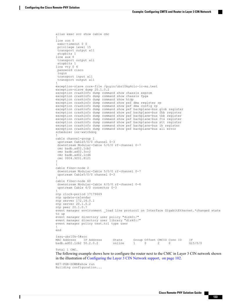
alias exec scc show cable cmc!line con 0exec-timeout 0 0privilege level 15transport output allstopbits 1line aux 0transport output allstopbits 1line vty 0 4password ciscologintransport input alltransport output all!exception-slave core-file /guyin/ubr10kg4clc-lc-mz.testexception-slave dump 20.1.0.2exception crashinfo dump command show chassis eepromexception crashinfo dump command show chassis fpgaexception crashinfo dump command show htdpexception crashinfo dump command show pxf dma register rpexception crashinfo dump command show pxf dma config rpexception crashinfo dump command show pxf backplane-bus glob registerexception crashinfo dump command show pxf backplane-bus fbb registerexception crashinfo dump command show pxf backplane-bus tbb registerexception crashinfo dump command show pxf backplane-bus fts registerexception crashinfo dump command show pxf backplane-bus stt registerexception crashinfo dump command show pxf backplane-bus ib registerexception crashinfo dump command show pxf backplane-bus all errorscheduler isr-watchdog!cable channel-group 1upstream Cable5/0/0 channel 0-3downstream Modular-Cable 5/0/0 rf-channel 0-7cmc badb.ad02.1cb2cmc badb.ad02.3cc2cmc badb.ad02.1cd6cmc 0004.9f01.8121!!cable fiber-node 2downstream Modular-Cable 5/0/0 rf-channel 0-7upstream Cable5/0/0 channel 0-3!cable fiber-node 60downstream Modular-Cable 6/0/0 rf-channel 0-6upstream Cable 6/0 connector 0-3!ntp clock-period 17179669ntp update-calendarntp server 172.16.0.1ntp server 20.1.0.2ntp peer 20.1.0.7event manager environment _load Line protocol on Interface GigabitEthernet.*changed stateto upevent manager directory user policy "disk0:/"event manager directory user library "disk0:/"event manager policy test.tcl type user!end
issu-ubr10k-5#sccMAC Address IP Address State Group Offset CMCID Conn ID IFbadb.ad02.1cb2 50.2.0.2 online 1 0 2 0 Gi5/0/0
Total 1 CMC.The following example shows how to configure the router next to the CMC in Layer 3 CIN network shownin the illustration of Configuring the Layer 3 CIN Network support, on page 102.NS7-PGN-DOWN#show runBuilding configuration...
Cisco Remote-PHY Solution Guide 133
Configuring the Cisco Remote-PHY SolutionExample: Configuring CMTS and Router in Layer 3 CIN Network
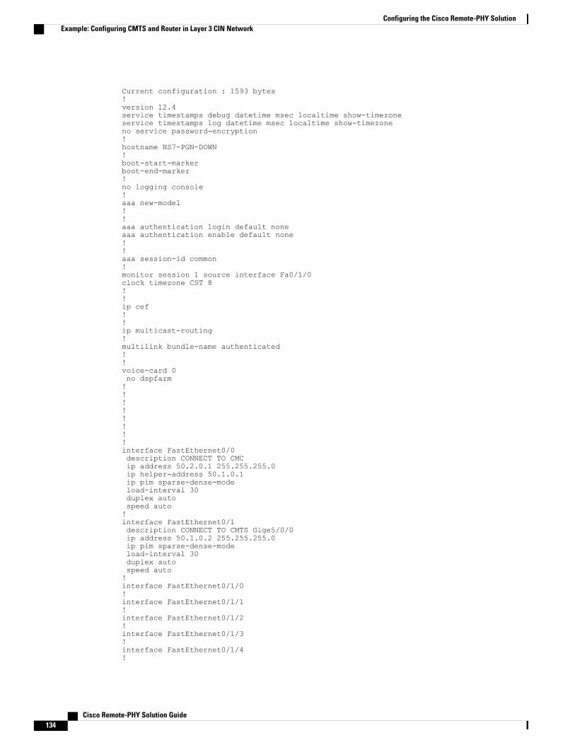
Current configuration : 1593 bytes!version 12.4service timestamps debug datetime msec localtime show-timezoneservice timestamps log datetime msec localtime show-timezoneno service password-encryption!hostname NS7-PGN-DOWN!boot-start-markerboot-end-marker!no logging console!aaa new-model!!aaa authentication login default noneaaa authentication enable default none!!aaa session-id common!monitor session 1 source interface Fa0/1/0clock timezone CST 8!!ip cef!!ip multicast-routing!multilink bundle-name authenticated!!voice-card 0no dspfarm!!!!!!!!interface FastEthernet0/0description CONNECT TO CMCip address 50.2.0.1 255.255.255.0ip helper-address 50.1.0.1ip pim sparse-dense-modeload-interval 30duplex autospeed auto!interface FastEthernet0/1description CONNECT TO CMTS Gige5/0/0ip address 50.1.0.2 255.255.255.0ip pim sparse-dense-modeload-interval 30duplex autospeed auto!interface FastEthernet0/1/0!interface FastEthernet0/1/1!interface FastEthernet0/1/2!interface FastEthernet0/1/3!interface FastEthernet0/1/4!
Cisco Remote-PHY Solution Guide134
Configuring the Cisco Remote-PHY SolutionExample: Configuring CMTS and Router in Layer 3 CIN Network
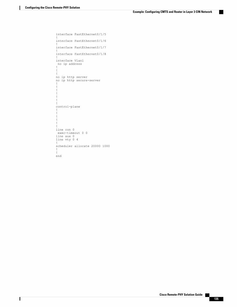
interface FastEthernet0/1/5!interface FastEthernet0/1/6!interface FastEthernet0/1/7!interface FastEthernet0/1/8!interface Vlan1no ip address!!!no ip http serverno ip http secure-server!!!!!!!control-plane!!!!!!line con 0exec-timeout 0 0line aux 0line vty 0 4!scheduler allocate 20000 1000!!end
Cisco Remote-PHY Solution Guide 135
Configuring the Cisco Remote-PHY SolutionExample: Configuring CMTS and Router in Layer 3 CIN Network

Cisco Remote-PHY Solution Guide136
Configuring the Cisco Remote-PHY SolutionExample: Configuring CMTS and Router in Layer 3 CIN Network

C H A P T E R 5Upgrading the Cisco Remote-PHY Solution
• Upgrading the Cisco CMC Image through the Cisco CMTS, page 137
• Upgrading the Cisco CMC Image through the Cisco CMC Console, page 139
Upgrading the Cisco CMC Image through the Cisco CMTSThe Cisco CMC consists of the following three images:
• Golden image
• Bank 1 image
• Bank 2 image
Golden Image
The image on the Cisco CMC that is downloaded as part of the factory settings is called the golden image.This image is read-only and cannot be deleted or replaced using the CLI. This image supports only theCisco CMC image upgrade and does not support the other features.
Bank 1 and Bank 2 Images
The non-golden images on the Cisco CMC that support all the features are called the bank 1 and bank 2images. These images can be copied to or deleted from the Cisco CMC. When the Cisco CMC image isupgraded, the bank 1 and bank 2 images are upgraded alternately. That is, if the last upgraded image is thebank 1 image, then the bank 2 image is upgraded with the current upgrade, and vice versa. When the image(non-golden) upgrade fails, the Cisco CMC tries to boot with the image from the other bank. If the imagesfrom both the banks fail, the Cisco CMC boots with the golden image.
Before You Begin
Before upgrading the Cisco CMC image through the Cisco CMTS, you must specify the TFTP or FTP serveraddress and full file path in the DHCP server.
If you are using a Cisco Network Registrar as the DHCP server, you must specify the values for the followingfields:
• packet-file-name
• packet-server-name
Cisco Remote-PHY Solution Guide 137

For more information on the Cisco Network Registrar, see Cisco Network Registrar.
The figure below shows an example of how to specify the values in the Cisco Network Registrar:
Figure 45: Specifying the Values on Cisco Network Registrar
Specify the new image file name and its full path1
Specify the TFTP or FTP server address where the new image is located2
Restriction
While upgrading the software images on Cisco CMTS and Cisco CMC, upgrade the Cisco CMC first, andthen upgrade the Cisco CMTS.
If the Cisco CMTS is upgraded before the Cisco CMC, the Cisco CMC may not come online.Important
Step 1 Enable the privileged EXEC mode using the enable command. Enter your password, if prompted.
Example:Router> enable
Step 2 Upgrade the Cisco CMC image using the cable cmc mac-address image_upgrade command.mac-address—MAC address of the Cisco CMC.
Example:Router# cable cmc 0001.0002.0003 image_upgrade
What to Do Next
If you are unable to upgrade the Cisco CMC image through Cisco CMTS, upgrade it through the Cisco CMCconsole. For more information, see Upgrading the Cisco CMC Image through the Cisco CMC Console, onpage 139.
Cisco Remote-PHY Solution Guide138
Upgrading the Cisco Remote-PHY SolutionUpgrading the Cisco CMC Image through the Cisco CMTS

Upgrading the Cisco CMC Image through the Cisco CMC Console
Perform this procedure only if you are unable to upgrade the Cisco CMC image through the Cisco CMTS.Important
Restriction
While upgrading the software images on Cisco CMTS and Cisco CMC, upgrade the Cisco CMC first, andthen upgrade the Cisco CMTS.
If the Cisco CMTS is upgraded before the Cisco CMC, the Cisco CMC may not come online.Important
Step 1 Open the Cisco CMC lid. See Opening the Cisco CMC, on page 42.Step 2 Connect the console cable to the Cisco CMC console port and connect the other end of the console cable to a computer.
See Using the Console Port on the Cisco CMC, on page 147.Step 3 Log in to the Cisco CMC console using telnet.
Use a baud rate of115200.
Note
Step 4 Enable the privilege mode on the Cisco CMC using the enable command. Enter your password, if prompted.
Example:CMC> enable
Step 5 Upgrade the Cisco CMC image using the upgrade system url command.url—Firmware path, where the image is available.
The firmware path iscase-sensitive.
Tip
If the image version available on the specified firmware path is the same as the image running on the Cisco CMCcurrently, the Cisco CMC does not upgrade the image.
Note
Example:CMC# upgrade system tftp://192.168.1.1/image-1.1.bin
Step 6 After the image upgrade is completed, disconnect the console cable from the Cisco CMC console port.Step 7 Close the Cisco CMC lid. See Closing the Cisco CMC, on page 74.
Cisco Remote-PHY Solution Guide 139
Upgrading the Cisco Remote-PHY SolutionUpgrading the Cisco CMC Image through the Cisco CMC Console

Cisco Remote-PHY Solution Guide140
Upgrading the Cisco Remote-PHY SolutionUpgrading the Cisco CMC Image through the Cisco CMC Console

C H A P T E R 6Maintaining and Monitoring the CiscoRemote-PHY Solution
This section provides information on how to maintain and monitor the Cisco Remote-PHY solution.
• Monitoring the Cisco Remote-PHY Solution, page 141
• Maintaining the Cisco Remote-PHY Solution, page 147
Monitoring the Cisco Remote-PHY Solution
Verifying the Cisco CMC Using the LEDsVerify the following LEDs located inside the Cisco CMC to check if it is operational.
DescriptionStatusLED
The Cisco CMC is not powered up.OffPWR
The Cisco CMC is powered up.Green
Passive Optical Network (PON) or Metro Ethernet is notconnected.
OffUPLINK
PON or Metro Ethernet is connected.Green
PON orMetro Ethernet is connected and transmitting data.Green (blinking)
Downstream RF is not connected.OffDS RF
Downstream RF is connected.Green
Cisco Remote-PHY Solution Guide 141

DescriptionStatusLED
The Cisco CMC is working.OffALARM
Indicates one of the following:
• The power received on the Optical Network Unit(ONU) is less than -25 dBm, unstable or unable tobuild link between Optical Line Terminal (OLT) andONU.
• Voltage or current has exceeded the major thresholdvalue.
• Temperature has exceeded the major threshold value.
Yellow (major alarm)
Indicates one of the following:
• Voltage or current has exceeded the critical thresholdvalue and the Cisco CMC must be shut down.
• Temperature has exceeded the critical threshold valueand the Cisco CMC must be shut down.
• The switch chipset is not working and unable to readthe register.
Red (critical alarm)
The Cisco CMC has not booted or run the power-onself-test (POST).
OffSTATUS
The Cisco CMC is connected to the Cisco CMTS and hasreceived an IP address.
Green
The Cisco CMC is in bootup mode and running thepower-on self-test.
Green (blinking)
Reserved for future use.OffRESERVED
The RJ-45 Gigabit Ethernet port is not connected on theCisco CMC.
OffGE0 and GE1
The RJ-45 Gigabit Ethernet port is connected on theCisco CMC.
Green
The RJ-45 Gigabit Ethernet port is connected on theCisco CMC and transmitting data.
Green (blinking)
Verify the following LEDs located inside the Cisco CMC to check if the FRx is operational.
Cisco Remote-PHY Solution Guide142
Maintaining and Monitoring the Cisco Remote-PHY SolutionVerifying the Cisco CMC Using the LEDs

DescriptionStatusLED
There is no power.OffCOMM
There is no communication.Green
Communication is working.Green (blinking)
Optical input level is normal (optical input level ≥ -6 dBm)OffOPTICAL POWER
Low optical input level ( -10 dBm ≤ optical input level <-6 dBm)
Red (blinking)
No optical input (optical input level < -10 dBm)Red
Verifying the Cisco CMC Using the CLI
Using the Cisco CMTS Commands
Use the following commands on the Cisco CMTS to verify the Cisco CMC configuration.
Table 17: Commands for Monitoring the Cisco CMC using the Cisco CMTS
PurposeCommand
Displays the Cisco CMC information.show cable cmc
Displays information on the associated Cisco CMCsin the channel group.
show cable channel-group
Using the Cisco CMC Commands
Use the following commands on the Cisco CMC console to verify the Cisco CMC configuration.
Table 18: Commands for Monitoring the Cisco CMC using the Cisco CMC Console
PurposeCommand
Displays the FRx information on the Cisco CMC.show frx
Displays the FRx alarm information on theCisco CMC.
show frx alarm
Displays the statistics information for the GenericControl Protocol (GCP) Exchange Data Structure(EDS) messages at command level.
show gcp config command stats info
Cisco Remote-PHY Solution Guide 143
Maintaining and Monitoring the Cisco Remote-PHY SolutionVerifying the Cisco CMC Using the CLI

PurposeCommand
Displays the statistics information for the GCP EDSmessages at operation code level.
show gcp config op stats info
Displays the statistics information for the GCP EDSmessages at TLV level.
show gcp config subtype stats info
Displays the GCP statistics information.show gcp stats
Displays the basic hardware information of theCisco CMC.
show hardware
Displays the current information of the hardwaresensor monitors on the Cisco CMC.
show hardware alarm active
Displays information on the history of the hardwaresensor monitors on the Cisco CMC.
show hardware alarm history
Displays the alarm threshold information for thehardware sensor monitors on the Cisco CMC.
show hardware alarm threshold
Displays the current Internet Group ManagementProtocol (IGMP) status on the Cisco CMC.
show igmp status
Display the Cisco CMC error log files.show log file
Displays the Optical Network Unit (ONU)information.
show onu
Displays the Power Supply Unit (PSU) information.show psu
Displays the basic system information of theCisco CMC.
show system
For more information on the Cisco CMC commands, see Cisco CoaxialMedia Converter Command Reference.
Verifying the Cisco uBR-MC3GX60V-RPHY Line Card Installation Using LEDsVerify the following LEDs on the Cisco uBR-MC3GX60V-RPHY line card to check if it is operational.
Cisco Remote-PHY Solution Guide144
Maintaining and Monitoring the Cisco Remote-PHY SolutionVerifying the Cisco uBR-MC3GX60V-RPHY Line Card Installation Using LEDs

Table 19: LEDs on the Cisco uBR-MC3GX60V-RPHY Line Card
DescriptionStatusLED
The Cisco uBR-MC3GX60V-RPHY line card is notpowered on.
OffPOWER
The Cisco uBR-MC3GX60V-RPHY line card is notpowered on.
Green
The Cisco uBR-MC3GX60V-RPHY line card is poweredon.
OffSTATUS
The processor on the Cisco uBR-MC3GX60V-RPHY linecard has booted and passed the diagnostics, or is in thestandby mode.
Green
The Cisco uBR-MC3GX60V-RPHY line card is in bootupmode.
Yellow
No action is required.OffMAINT
It is safe to remove the Cisco uBR-MC3GX60V-RPHYline card.
Yellow
The DEPI port is not enabled.OffGE0 and GE1
The DEPI port is configured and is able to send traffic.Green
The Ethernet link is not working.OffLK/ACT0-LK/ACT5
The Gigabit Ethernet port is enabled and the Ethernet linkis working, and there is no US or DS traffic flow.
Green (steady)
The Gigabit Ethernet port is enabled and the Ethernet linkis working, and there is US or DS traffic flow.
Green (blinking)
Verifying the Cisco uBR-MC3GX60V-RPHY Line Card Using the CLIVerify the Cisco uBR-MC3GX60V-RPHY line card using the following commands:
Cisco Remote-PHY Solution Guide 145
Maintaining and Monitoring the Cisco Remote-PHY SolutionVerifying the Cisco uBR-MC3GX60V-RPHY Line Card Using the CLI

Table 20: Commands Used to Verify the Cisco uBR-MC3GX60V-RPHY Line Card
PurposeCommand
Displays the MAC domain information toverify the bonding operation on theCisco uBR-MC3GX60V-RPHY line card.
• show cable mac-domain cable cgd-associations
• show cable mac-domain cabledownstream-service-group
• show cable mac-domain cable forwarding
• show cable mac-domain cable rcc
• show cablemac-domain cable upstream-service-group
Displays the software license of theCisco uBR-MC3GX60V-RPHY line card.• show cable license
• show license detail
Displays theCisco uBR-MC3GX60V-RPHY line cardStatistics.
This command allows the user to view thefollowing line card statistics:
• Interface association
• JIB hardware downstreamconfiguration
• Channel counters
• Errors
• Mapping of wideband and RFchannels
• JIB hardware downstream registers
• JIB hardware downstream status
show controller modular-cable
Displays the interface controllersinformation on theCisco uBR-MC3GX60V-RPHY line card.
• show controllers cable slot/subslot/port
• show interface cable slot/subslot/cable-interface-index
Displays the Cable modem information.show cable modem
Displays the DOCSIS Timing and ControlCard (DTCC) and its current status.
show cable clock
Cisco Remote-PHY Solution Guide146
Maintaining and Monitoring the Cisco Remote-PHY SolutionVerifying the Cisco uBR-MC3GX60V-RPHY Line Card Using the CLI

PurposeCommand
Displays information about the SFPmodules on theCisco uBR-MC3GX60V-RPHY line card.
If the SFP module is not present, thefollowing output is displayed:SFP in Port1 is NOT PRESENT
show controllers modular-cable sfp
Displays the bidirectional communicationbetween the Cisco CMTS and the CiscoCMC.
The Cisco uBR-MC3GX60V-RPHY linecard has three Gigabit Ethernet interfaces.When an IP address is configured on theGigabit Ethernet interface in a subnet thatincludes the Cisco CMC, the IP addressof the Cisco CMC becomes pingable.
show ip interfaces brief
Displays the hardware and diagnosticinformation of theCisco uBR-MC3GX60V-RPHY line card.
show diag
Maintaining the Cisco Remote-PHY Solution
Using the Console Port on the Cisco CMCThe console port on the Cisco CMC is used for connecting the Cisco CMC to a PC using a console cable.
The console cable connection is only for initial installation and maintenance of the Cisco CMC. Theconsole cable must not be connected during electromagnetic compliance testing. The console cable mustbe disconnected from the Cisco CMC after the final installation.
Warning
Cisco Remote-PHY Solution Guide 147
Maintaining and Monitoring the Cisco Remote-PHY SolutionMaintaining the Cisco Remote-PHY Solution

The figure below shows the console cable used with the Cisco CMC.
Figure 46: Console Cable
Pin 3 (P3)3DB9 connector1
PCB connector4Pin 2 (P2)2
The table below provides the console cable connector pin definitions.
Table 21: Console Cable—Connector Pin Definitions
DefinitionPin Number
Ground (GND)Pin 1
Input (UART_RX)Pin 2
Ground (GND)Pin 3
Output (UART_TX)Pin 4
Golden image (Golden_Image)Pin 5
Ground (GND)Pin 6
Cisco Remote-PHY Solution Guide148
Maintaining and Monitoring the Cisco Remote-PHY SolutionUsing the Console Port on the Cisco CMC

Before You Begin
• Open the Cisco CMC lid. See Opening the Cisco CMC, on page 42.
• Have the following tools ready before performing this task:
◦Screwdriver
Step 1 Remove the screws on the console port cover using a screwdriver to access the console port. The figure below showsthe console port with its cover.
Figure 47: Cisco CMC Console Port
—Console port cover1
Step 2 Align the PCB connector of the console cable with the pins on the Cisco CMC console port and insert the PCB connectorinto the console port.
Step 3 (Optional) To boot the Cisco CMC with the golden image, insert P2 into P3.If P2 is not connected to P3, the Cisco CMC bootsnormally.
Tip
Step 4 Connect the DB9 connector of the console cable with the appropriate serial port on the PC.Step 5 Power up the PC.Step 6 Configure the PC terminal emulation software with the following default settings for the Cisco CMC:
• 115200 baud rate
• 8 data bits
• No parity generation or checking
• 1 stop bit
Cisco Remote-PHY Solution Guide 149
Maintaining and Monitoring the Cisco Remote-PHY SolutionUsing the Console Port on the Cisco CMC

What to Do Next
1 Disconnect the console cable from the console port.
2 Reinstall the console port cover and tighten the screws using a screwdriver.
3 Close the Cisco CMC lid. See Closing the Cisco CMC, on page 74.
Removing the Coaxial Cable from the Cisco CMC
Before You Begin
• Open the Cisco CMC lid. See Opening the Cisco CMC, on page 42.
• Have the following tools ready before performing this task:
◦Torque wrench
Cisco Remote-PHY Solution Guide150
Maintaining and Monitoring the Cisco Remote-PHY SolutionRemoving the Coaxial Cable from the Cisco CMC

◦Slot screwdriver
Step 1 Remove the coaxial cable from the F-connector installed in the RF port.Step 2 Loosen the seizure screw, do not remove it. The figure below shows the location of the seizure screw inside the Cisco CMC.
Figure 48: Location of the Seizure Screw
—Seizure screw1
Step 3 Loosen the connector nut using a torque wrench and remove the F-connector from the RF port.Step 4 Reinstall the PG11-to-5/8" adapter plug in the RF port and tighten using a torque wrench (4.63 ft-lb or 6.25 Nm), if you
removed a PG11 F-connector from the RF port.Step 5 Check if RF signal is present at the unused RF ports and perform one of the following:
• If RF signal is present, insert a 75 ohm terminator into the RF port and tighten according to the manufacturerspecifications.
Cisco Remote-PHY Solution Guide 151
Maintaining and Monitoring the Cisco Remote-PHY SolutionRemoving the Coaxial Cable from the Cisco CMC

• If RF signal is not present, insert a 5/8" port plug into the RF port and tighten from 5 ft-lb to 8 ft-lb (6.8 Nm to10.8 Nm) using a torque wrench.
What to Do Next
• To install the F-connector and connect the coaxial cable to the Cisco CMC, see Installing the CoaxialCables on the Cisco CMC, on page 46.
• Close the Cisco CMC lid. See Closing the Cisco CMC, on page 74.
Cisco Remote-PHY Solution Guide152
Maintaining and Monitoring the Cisco Remote-PHY SolutionRemoving the Coaxial Cable from the Cisco CMC

Removing the Fiber Adapter from the Cisco CMC
Before You Begin
Open the Cisco CMC lid. See Opening the Cisco CMC, on page 42.
Step 1 Disconnect the optical fibers connected to the fiber adapter. Immediately reinstall the dust plugs in the fiber adapters.Step 2 Remove the fiber adapter from the slot as shown in the figure below:
Figure 49: Removing the Fiber Adapter from the Cisco CMC
Cisco Remote-PHY Solution Guide 153
Maintaining and Monitoring the Cisco Remote-PHY SolutionRemoving the Fiber Adapter from the Cisco CMC
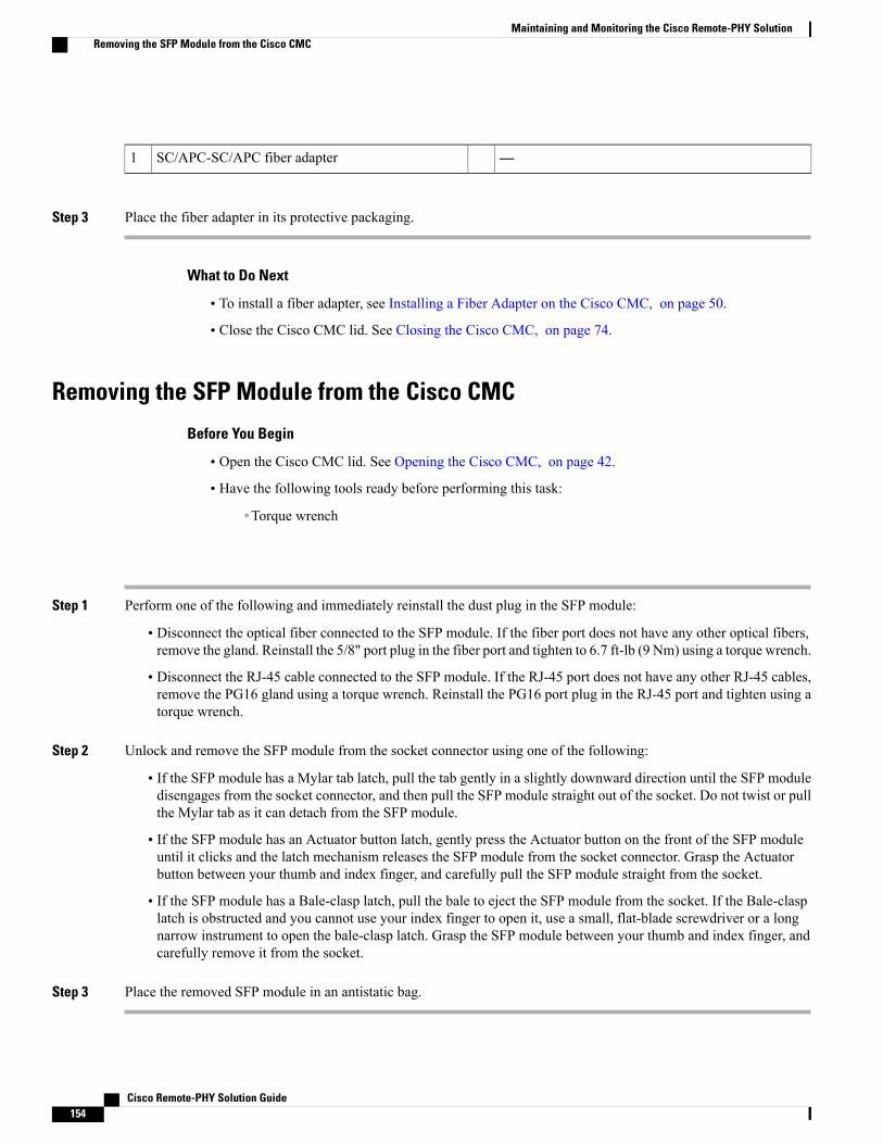
—SC/APC-SC/APC fiber adapter1
Step 3 Place the fiber adapter in its protective packaging.
What to Do Next
• To install a fiber adapter, see Installing a Fiber Adapter on the Cisco CMC, on page 50.
• Close the Cisco CMC lid. See Closing the Cisco CMC, on page 74.
Removing the SFP Module from the Cisco CMC
Before You Begin
• Open the Cisco CMC lid. See Opening the Cisco CMC, on page 42.
• Have the following tools ready before performing this task:
◦Torque wrench
Step 1 Perform one of the following and immediately reinstall the dust plug in the SFP module:
• Disconnect the optical fiber connected to the SFP module. If the fiber port does not have any other optical fibers,remove the gland. Reinstall the 5/8" port plug in the fiber port and tighten to 6.7 ft-lb (9 Nm) using a torque wrench.
• Disconnect the RJ-45 cable connected to the SFP module. If the RJ-45 port does not have any other RJ-45 cables,remove the PG16 gland using a torque wrench. Reinstall the PG16 port plug in the RJ-45 port and tighten using atorque wrench.
Step 2 Unlock and remove the SFP module from the socket connector using one of the following:
• If the SFP module has a Mylar tab latch, pull the tab gently in a slightly downward direction until the SFP moduledisengages from the socket connector, and then pull the SFP module straight out of the socket. Do not twist or pullthe Mylar tab as it can detach from the SFP module.
• If the SFP module has an Actuator button latch, gently press the Actuator button on the front of the SFP moduleuntil it clicks and the latch mechanism releases the SFP module from the socket connector. Grasp the Actuatorbutton between your thumb and index finger, and carefully pull the SFP module straight from the socket.
• If the SFP module has a Bale-clasp latch, pull the bale to eject the SFP module from the socket. If the Bale-clasplatch is obstructed and you cannot use your index finger to open it, use a small, flat-blade screwdriver or a longnarrow instrument to open the bale-clasp latch. Grasp the SFP module between your thumb and index finger, andcarefully remove it from the socket.
Step 3 Place the removed SFP module in an antistatic bag.
Cisco Remote-PHY Solution Guide154
Maintaining and Monitoring the Cisco Remote-PHY SolutionRemoving the SFP Module from the Cisco CMC

What to Do Next
• To install the SFP module, see Installing an SFP Module on the Cisco CMC, on page 52.
• Close the Cisco CMC lid. See Closing the Cisco CMC, on page 74.
Online Insertion and Removal of the Cisco uBR-MC3GX60V-RPHY Line CardYou can replace a Cisco uBR-MC3GX60V-RPHY line card with only a Cisco uBR-MC3GX60V-RPHY linecard.
Before You Begin
• Save the Cisco uBR-MC3GX60V-RPHY line card configurations before starting the OIR.
• Change the standby card (if available) to HOT state.
• Save the startup configuration file before any reload of the system (if there is a need to reload), after asuccessful OIR.
• Perform OIR when the Cisco CMTS is up and running.
Restriction • The OIR cannot be used if you want to upgrade to Cisco uBR-MC3GX60V-RPHY line card directlyfrom any of the old line card ( Cisco uBR-MC3GX60V, Cisco uBR10-MC5X20H, CiscoUBR-MC20X20V)other than LC like 520 or 20x20 to 3G60.
• OIR cannot be performed when the standby PRE is being loaded.
Step 1 Enter the cr10k card oir-compatibility command for the existing Cisco uBR-MC3GX60V-RPHY line card.
Example:Router(config)# cr10k card 8/0 oir-compatibility
This command preserves the configuration and performs internal synchronization to ensure that the OIR runs successfully.
Step 2 Save the configuration to ensure the transition.
Example:Router# copy running-config startup-config
Step 3 Power down the existing Cisco uBR-MC3GX60V-RPHY line card using cable power off command.
Example:Router# cable power off 8/0Line Card 8/0 is POWERED OFF
Cisco Remote-PHY Solution Guide 155
Maintaining and Monitoring the Cisco Remote-PHY SolutionOnline Insertion and Removal of the Cisco uBR-MC3GX60V-RPHY Line Card

This powers off the Cisco uBR-MC3GX60V-RPHY line card gracefully.
Step 4 Before removing the existing Cisco uBR-MC3GX60V-RPHY line card, verify that the proper grounding instructionshave been followed.
Step 5 Remove the existing Cisco uBR-MC3GX60V-RPHY line card from the slot.See Removing the Existing Line Card from the Card Slot, on page 78.
Step 6 Install the new Cisco uBR-MC3GX60V-RPHY line card in the slot.See Installing the Cisco uBR-MC3GX60V-RPHY Line Card in the Card Slot, on page 80.
Step 7 Power up the new Cisco uBR-MC3GX60V-RPHY line card using the cable power on command.
Example:Router# cable power on 8/0
Step 8 Verify that the new Cisco uBR-MC3GX60V-RPHY line card and line protocol is up using the show interface cablecommand.
Example:Router# show interface cable 8/0/0Cable8/0/0 is up, line protocol is upHardware is BCM3210 ASIC, address is 010a.13e8.1ca8 (bia 010a.13e8.1a60)Internet address is 192.1.1.3/24MTU 1500 bytes, BW 27000 Kbit, DLY 1000 usec, rely 255/255, load 1/255Encapsulation, loopback not set, keepalive not setARP type: ARPA, ARP Timeout 04:00:00Last input 4d07h, output 00:00:00, output hang neverLast clearing of "show interface" counters neverQueuing strategy: fifoOutput queue 0/40, 0 drops; input queue 0/75, 0 drops5 minute input rate 1834000 bits/sec, 2385 packets/sec5 minute output rate 1982000 bits/sec, 2431 packets/sec24461542 packets input, 2348214388 bytes, 0 no bufferReceived 1979 broadcasts, 0 runts, 0 giants, 0 throttles0 input errors, 0 CRC, 0 frame, 0 overrun, 0 ignored, 0 abort24854257 packets output, 2536222931 bytes, 0 underruns0 output errors, 0 collisions, 0 interface resets0 output buffer failures, 0 output buffers swapped out
Step 9 Verify the hardware status using the show controllers cable command.
Example:Router# show controllers cable 8/0/0Cable8/0/0 JIB hardware status:JIB Downstream port EnabledJIB Upstream port 0 EnabledJIB Upstream port 1 EnabledJIB Upstream port 2 EnabledJIB Upstream port 3 EnabledCable8/0/0 Upconverter is Enabled Output is Enabled
Step 10 Verify the configuration with the show running-configuration command.
Cisco Remote-PHY Solution Guide156
Maintaining and Monitoring the Cisco Remote-PHY SolutionOnline Insertion and Removal of the Cisco uBR-MC3GX60V-RPHY Line Card

C H A P T E R 7Troubleshooting the Cisco Remote-PHY Solution
This section provides the troubleshooting procedures for the Cisco Remote-PHY solution.
show cable cmc command can be used to identify the status of CMC in first hand.issu-ubr10k-5#show cable cmcMAC Address IP Address State Group Offset CMCID Conn ID IF9078.5634.1200 0.0.0.0 init(d) 0 0 1 N/A Gi7/0/0
Note
The table below shows the description of each state.
Table 22: CMC State Description
DescriptionState
CMC is not operationalOffline
IP assign failedReject(i)
DHCP discoveryInit(d)
GCP connection establishingInit(g)
GCP connection establishedInit(est)
Get CMC CapabilityInit(c)
Download configuration to CMCInit(s)
Get CMC Capability failedReject(c)
CMC is operationalOnline
• Troubleshooting the Cisco Remote-PHY Solution, page 158
• Troubleshooting: Cisco uBR-MC3GX60V-RPHYLine Card Link LEDDoes Not Illuminate, page 158
Cisco Remote-PHY Solution Guide 157
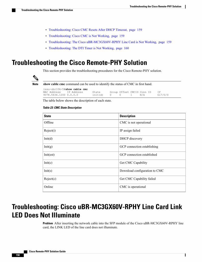
• Troubleshooting: Cisco CMC Resets After DHCP Timeout, page 159
• Troubleshooting: Cisco CMC is Not Working, page 159
• Troubleshooting: The Cisco uBR-MC3GX60V-RPHY Line Card is Not Working, page 159
• Troubleshooting: The DTI Timer is Not Working, page 160
Troubleshooting the Cisco Remote-PHY SolutionThis section provides the troubleshooting procedures for the Cisco Remote-PHY solution.
show cable cmc command can be used to identify the status of CMC in first hand.issu-ubr10k-5#show cable cmcMAC Address IP Address State Group Offset CMCID Conn ID IF9078.5634.1200 0.0.0.0 init(d) 0 0 1 N/A Gi7/0/0
Note
The table below shows the description of each state.
Table 23: CMC State Description
DescriptionState
CMC is not operationalOffline
IP assign failedReject(i)
DHCP discoveryInit(d)
GCP connection establishingInit(g)
GCP connection establishedInit(est)
Get CMC CapabilityInit(c)
Download configuration to CMCInit(s)
Get CMC Capability failedReject(c)
CMC is operationalOnline
Troubleshooting: Cisco uBR-MC3GX60V-RPHY Line Card LinkLED Does Not Illuminate
Problem After inserting the network cable into the SFP module of the Cisco uBR-MC3GX60V-RPHY linecard, the LINK LED of the line card does not illuminate.
Cisco Remote-PHY Solution Guide158
Troubleshooting the Cisco Remote-PHY SolutionTroubleshooting the Cisco Remote-PHY Solution

Possible Cause Dirt or skin oil is accumulated on the network cable plug faceplate generating significantattenuation and reducing the optical power levels below threshold levels. This could result in link failure.
Solution Clean the plug faceplate with a lint-free tissue soaked in 99 percent pure isopropyl alcohol and thenwith a dry lint-free tissue. Remove any residual dust from the faceplate with compressed air before installingthe network cable.
Troubleshooting: Cisco CMC Resets After DHCP TimeoutProblem The Cisco CMC is reset after DHCP timeout.
Possible Cause The DHCP server address is not specified in the Gigabit Ethernet interface of theCisco uBR-MC3GX60V-RPHY line card.
Solution Verify the Gigabit Ethernet Interface configuration on the Cisco uBR-MC3GX60V-RPHY line card.To specify the DCHP server address, use the ip helper-address command. For more information, seeConfiguring the Gigabit Ethernet Interface on the Cisco uBR-MC3GX60V-RPHY Line Card, on page 88.
Troubleshooting: Cisco CMC is Not WorkingProblem The Cisco CMC is online but the cable modem fails to come online.
Possible Cause The Cisco uBR-MC3GX60V-RPHY line card is not properly configured.
Solution Verify the configuration on the Cisco uBR-MC3GX60V-RPHY line card. See Configuring the CiscoRemote-PHY Solution, on page 87.
Possible Cause The Cisco CMC is not properly connected to the line card.
Solution Verify the connection between Cisco uBR-MC3GX60V-RPHY line card and Cisco CMC.
Troubleshooting: The Cisco uBR-MC3GX60V-RPHY Line Card isNot Working
Problem The Cisco uBR-MC3GX60V-RPHY line card is not working.
Possible Cause The Cisco uBR-MC3GX60V-RPHY line card is not connected to the power supply.
Solution Verify if the power LED is illuminated and the power supply is connected to theCisco uBR-MC3GX60V-RPHY line card. Connect to the power supply, if not connected.
Possible Cause The Cisco uBR-MC3GX60V-RPHY line card is not configured on the Cisco CMTS.
Solution Configure the Cisco uBR-MC3GX60V-RPHY line card. See Configuring the Cisco Remote-PHYSolution, on page 87.
Cisco Remote-PHY Solution Guide 159
Troubleshooting the Cisco Remote-PHY SolutionTroubleshooting: Cisco CMC Resets After DHCP Timeout

Possible Cause The captive screws are not secured on the faceplate and the ejector levers are not properlyclosed.
Solution Close the ejector levers and tighten the captive screws with your fingers. Then, use either a T-10Torx or a common flathead screwdriver to tighten the captive screws from 5 to 7 in-lbs.
Possible Cause The Cisco uBR-MC3GX60V-RPHY line card is not firmly seated in the chassis.
Solution Unscrew the top and bottom captive screws on the line card using a T-10 Torx driver tool or flatheadscrewdriver. Simultaneously pivot both ejector levers away from the line card to disengage the line card. Slidethe line card partially out of the slot in the chassis and slide it back in until it is firmly seated in the chassis.Close the ejector levers and tighten the captive screws with your fingers. Then, use either a T-10 Torx or acommon flathead screwdriver to tighten the captive screws from 5 to 7 in-lbs.
Possible Cause The network cable connectors are not properly seated in the ports on theCisco uBR-MC3GX60V-RPHY line card and cables are broken.
Solution Verify if the cables are broken. Replace the cables, if broken and insert the network cable connectorinto the SFP module port until it clicks and locks into place to ensure proper seating..
Possible Cause Incorrect or inappropriate software license is configured on theCisco uBR-MC3GX60V-RPHY line card.
Solution Reinstall or rehost the appropriate license on the Cisco uBR-MC3GX60V-RPHY line card.
Possible Cause Power on Self Test (POST) fails when the line card is installed in the chassis.
Solution Verify the power supply connection and if the problem persists, contact the Technical AssistanceCenter (TAC) for further assistance.
Troubleshooting: The DTI Timer is Not WorkingProblem The DOCSIS Timing Interface (DTI) timer is not working correctly and the cable modems are notin init() state.
Possible Cause DTI-based timing is disabled on the active card.
Solution Use the show cable clock command to identify the active card and enable the DTI-based timingusing the cable clock dti command.
Cisco Remote-PHY Solution Guide160
Troubleshooting the Cisco Remote-PHY SolutionTroubleshooting: The DTI Timer is Not Working


