Cisco Prime Service Catalog 10.0 Configuration Guide · WebLogic 5-2 Restarting Cognos Server 5-2...
216
Americas Headquarters Cisco Systems, Inc. 170 West Tasman Drive San Jose, CA 95134-1706 USA http://www.cisco.com Tel: 408 526-4000 800 553-NETS (6387) Fax: 408 527-0883 Cisco Prime Service Catalog 10.0 Configuration Guide December 19, 2013 Text Part Number: OL-31034-01
Transcript of Cisco Prime Service Catalog 10.0 Configuration Guide · WebLogic 5-2 Restarting Cognos Server 5-2...

Cisco Prime Service Catalog 10.0 Configuration GuideDecember 19, 2013
Americas HeadquartersCisco Systems, Inc.170 West Tasman DriveSan Jose, CA 95134-1706 USAhttp://www.cisco.comTel: 408 526-4000
800 553-NETS (6387)Fax: 408 527-0883
Text Part Number: OL-31034-01

THE SPECIFICATIONS AND INFORMATION REGARDING THE PRODUCTS IN THIS MANUAL ARE SUBJECT TO CHANGE WITHOUT NOTICE. ALL STATEMENTS, INFORMATION, AND RECOMMENDATIONS IN THIS MANUAL ARE BELIEVED TO BE ACCURATE BUT ARE PRESENTED WITHOUT WARRANTY OF ANY KIND, EXPRESS OR IMPLIED. USERS MUST TAKE FULL RESPONSIBILITY FOR THEIR APPLICATION OF ANY PRODUCTS.
THE SOFTWARE LICENSE AND LIMITED WARRANTY FOR THE ACCOMPANYING PRODUCT ARE SET FORTH IN THE INFORMATION PACKET THAT SHIPPED WITH THE PRODUCT AND ARE INCORPORATED HEREIN BY THIS REFERENCE. IF YOU ARE UNABLE TO LOCATE THE SOFTWARE LICENSE OR LIMITED WARRANTY, CONTACT YOUR CISCO REPRESENTATIVE FOR A COPY.
The Cisco implementation of TCP header compression is an adaptation of a program developed by the University of California, Berkeley (UCB) as part of UCB’s public domain version of the UNIX operating system. All rights reserved. Copyright © 1981, Regents of the University of California.
NOTWITHSTANDING ANY OTHER WARRANTY HEREIN, ALL DOCUMENT FILES AND SOFTWARE OF THESE SUPPLIERS ARE PROVIDED “AS IS” WITH ALL FAULTS. CISCO AND THE ABOVE-NAMED SUPPLIERS DISCLAIM ALL WARRANTIES, EXPRESSED OR IMPLIED, INCLUDING, WITHOUT LIMITATION, THOSE OF MERCHANTABILITY, FITNESS FOR A PARTICULAR PURPOSE AND NONINFRINGEMENT OR ARISING FROM A COURSE OF DEALING, USAGE, OR TRADE PRACTICE.
IN NO EVENT SHALL CISCO OR ITS SUPPLIERS BE LIABLE FOR ANY INDIRECT, SPECIAL, CONSEQUENTIAL, OR INCIDENTAL DAMAGES, INCLUDING, WITHOUT LIMITATION, LOST PROFITS OR LOSS OR DAMAGE TO DATA ARISING OUT OF THE USE OR INABILITY TO USE THIS MANUAL, EVEN IF CISCO OR ITS SUPPLIERS HAVE BEEN ADVISED OF THE POSSIBILITY OF SUCH DAMAGES.
Cisco and the Cisco logo are trademarks or registered trademarks of Cisco and/or its affiliates in the U.S. and other countries. To view a list of Cisco trademarks, go to this URL: www.cisco.com/go/trademarks. Third-party trademarks mentioned are the property of their respective owners. The use of the word partner does not imply a partnership relationship between Cisco and any other company. (1110R)
Any Internet Protocol (IP) addresses and phone numbers used in this document are not intended to be actual addresses and phone numbers. Any examples, command display output, network topology diagrams, and other figures included in the document are shown for illustrative purposes only. Any use of actual IP addresses or phone numbers in illustrative content is unintentional and coincidental.
Cisco Prime Service Catalog 10.0 Configuration Guide © 2013 Cisco Systems, Inc. All rights reserved.

OL-31034-01
C O N T E N T S
Preface xiii
Objectives xiii
Audience xiii
Document Organization xiii
Conventions xiv
Obtaining Documentation and Submitting a Service Request xv
C H A P T E R 1 Organization Design 1-1
Overview 1-1
Accessing Organization Designer 1-1
Organization Designer Home Page 1-2
Navigation 1-2
Search 1-2
Home Page Search 1-2
Component-Specific Search 1-3
Maintaining Organizational Entities 1-4
Creating an Entity 1-4
Copying an Existing Entity 1-4
Deactivating an Entity 1-5
Deleting an Entity 1-5
Administration 1-5
Organizational Entities and their Relationships 1-6
Directory Integration and Organizational Entities 1-6
Organizational Units 1-7
Maintaining Organizational Units 1-7
Service Teams 1-7
Business Units 1-7
Maintaining an Organizational Unit 1-7
Deactivating Organizational Units 1-8
Configuring Organizational Units 1-8
Organizational Unit Hierarchies 1-8
OU Members 1-9
Functional Positions 1-10
Organization-Level Authorization 1-11
iiiCisco Prime Service Catalog 10.0 Configuration Guide

Contents
Permissions 1-11
Roles 1-12
Administration 1-13
Groups 1-14
Configuring Groups 1-14
Configuring General Group Information 1-15
Adding or Removing Subgroups 1-15
Members 1-15
Roles 1-16
Using Groups in Service Design 1-16
Queues 1-19
Tips for Working with Queues 1-19
Configuring Queues 1-19
Configuring General Queue Information 1-19
Queue Organizational Units 1-20
Queue Contact 1-20
Queue Calendar 1-21
Queue Permissions 1-21
People 1-22
Creating New People 1-22
Configuring People 1-23
General Person Information 1-23
Assigning Organizational Units to People 1-24
Address Information 1-25
Contact Information 1-25
Extensions 1-26
Configuring a Person's Calendar 1-27
Assigning Permissions to a Person 1-28
Assigning Roles to a Person 1-29
Deactivating a Person 1-29
Deleting a Person 1-29
Functional Positions 1-30
Creating a New Functional Position 1-31
Modifying a Functional Position 1-31
Deleting a Functional Position 1-32
Roles 1-32
Role Hierarchy 1-32
System-Defined Roles 1-33
”Anyone” and “Site Administrator” Roles 1-35
ivCisco Prime Service Catalog 10.0 Configuration Guide
OL-31034-01

Contents
Searching for Roles 1-36
Configuring Roles 1-36
Assigning Members to a Role 1-37
Roles with Object-Level Permissions 1-38
Custom Roles 1-39
General Role Information 1-40
Role Hierarchies 1-40
Assigning Role Capabilities 1-41
Assigning Permissions 1-47
Modifying an Existing Role 1-51
Assigning Permissions to People with Custom Roles 1-52
Usage Scenarios to Create Sample Custom Roles 1-52
Support Team 1-52
Organization-Specific Service Team Administrator 1-53
Support Team for an External Application 1-53
Distributed Service Design 1-53
Support for Web Services 1-54
C H A P T E R 2 User Profiles 2-1
Overview 2-1
Information 2-1
Preferred Language 2-2
Calendar 2-2
Preferences 2-2
C H A P T E R 3 Site Administration 3-1
Overview 3-1
Administration Home 3-1
Directory Integration 3-2
Site-Wide Authorizations 3-2
Setting Up an Authorization Structure 3-2
Enabling Authorizations 3-2
Specifying Authorization Details 3-3
Escalations 3-7
Email Templates 3-8
Viewing Email Templates 3-8
Configuring Templates 3-9
Using Namespaces 3-9
vCisco Prime Service Catalog 10.0 Configuration Guide
OL-31034-01

Contents
Lists 3-9
Language 3-10
Site Settings 3-10
Customizations 3-11
Asynchronous Submission/Last Approval 3-11
Browser Cache Setting 3-12
JMS Credentials 3-12
Common Settings 3-13
Style-Related Settings 3-14
Directory Integration-Related Settings 3-14
Historical Requisition Partitioning 3-14
Catalog Deployer-Related Settings 3-16
My Services Settings 3-16
Form Monitor 3-18
Authorizations Portlet 3-18
Service Items Portlet 3-18
Requisitions Portlet 3-19
Common Tasks Portlet 3-19
My Services Portlets 3-19
Service Manager Settings 3-20
Service Link Settings 3-21
Person Popup 3-21
Entity Homes 3-22
Debugging 3-23
Debugging Settings 3-23
Monitor for Asynchronous Submission Messages 3-23
Custom Styles 3-23
Defining a Custom Style 3-24
Enabling Custom Style Sheets and Headers/Footers 3-25
Data Source Registry 3-25
Support Utilities 3-26
Logs and Properties 3-26
Log and Destination Folder Settings 3-27
View and Download Files 3-29
Purge Utilities 3-30
Performance Considerations for Executing Purge 3-31
Version History 3-31
Form Data Viewer 3-31
Adjusting Columns 3-32
Resizing a Column 3-32
viCisco Prime Service Catalog 10.0 Configuration Guide
OL-31034-01
Contents
Moving a Column 3-32
Sorting a Column 3-32
Hiding or Showing Columns 3-33
Undelivered Email 3-33
Run Processes 3-33
Recommendation for Datamart 3-34
C H A P T E R 4 Custom Style Sheets 4-1
Overview 4-1
Custom Style Sheets 4-1
Overview 4-1
Prerequisites 4-2
Customizing Built-In Modules 4-2
Customizing User-Defined Portals 4-3
Defining a Custom Style 4-3
Enabling Custom Style Sheets and Headers/Footers 4-4
Modifying Customizations with Browser Cache Enabled 4-5
Customizing Styles for Service Catalog Module 4-5
Customizing Styles for MyServices Module 4-7
Page Headers 4-7
Navigation Bars 4-8
Buttons 4-8
Service Forms 4-8
Preserving Customizations 4-9
Known Errors and Omissions 4-10
Unknown Errors and Omissions 4-10
Upgrading from Previous Versions 4-11
Style Summary and Recommended Practices 4-11
Style Summary – Built-In Modules 4-11
Style Summary – User-Defined Modules 4-16
Recommended Practices 4-17
Example Screenshot, and What Each Style Specifically Affects 4-18
Custom Headers and Footers 4-18
Overview 4-18
Procedure 4-18
Customizing Page Headers and Footers 4-19
C H A P T E R 5 System Administration 5-1
Overview 5-1
viiCisco Prime Service Catalog 10.0 Configuration Guide
OL-31034-01
Contents
Intended Audience 5-1
Terminology 5-2
Startup and Shutdown Procedures 5-2
JBoss 5-2
WebSphere 5-2
WebLogic 5-2
Restarting Cognos Server 5-2
Restarting using Cognos Configuration Manager 5-3
Restarting using Windows Services 5-3
Ongoing Infrastructure Maintenance Tasks 5-3
Backup Methodology 5-3
Application Server Tuning 5-3
Configuring Service Catalog Compression 5-3
Java Memory Settings 5-4
JMS Queue Connection Factory Settings 5-5
Upgrading/Replacing the JDK 5-5
Database Tuning 5-5
Specific Recommendations for Service Catalog 5-6
Tuning Oracle 5-6
Tuning SQLServer 5-7
Sizing Cognos Database Components 5-8
OLTP Database Tables 5-9
Performing Application Housekeeping 5-10
Historical Requisition Partitioning 5-10
Requisition Purge 5-12
Overview 5-12
Preparations 5-12
Using the Scripts 5-12
Workflow Purge 5-15
Running the Utility on an Oracle Database 5-16
Running the Utility on an SQL Server Database 5-16
Service Link Messages Purge 5-17
Running the Utility on an Oracle Database 5-18
Running the Utility on an SQL Server Database 5-18
Undelivered Emails 5-19
Managing the Application 5-19
The Basics 5-19
Deploying the Application 5-19
Restarting the Server 5-19
viiiCisco Prime Service Catalog 10.0 Configuration Guide
OL-31034-01
Contents
Key Configuration Files 5-19
Managing Logs 5-20
Sample Log File Entries 5-21
WebSphere Logging 5-21
WebLogic Logging 5-22
JBoss Logging 5-22
Data Sources 5-22
Creating “Backing Tables” for External Dictionaries 5-23
Sample SQL Listing to Create a Backing Table 5-23
Applying Maintenance Releases and Patches 5-23
Configuring Service Export via SSL or NTLM 5-23
Cisco Prime Service Catalog Cached Data 5-24
Cisco Prime Service Catalog Data Security 5-25
Application Security 5-26
Reporting 5-26
Reporting Batch Programs 5-26
Form-Data Extraction Script 5-27
Escalation Manager 5-28
Service Manager 5-28
Service Catalog Installation 5-28
Multicast Settings 5-29
Testing Multicast Connectivity 5-30
Managing Integrations 5-30
Integration Types 5-30
Directory Integration 5-31
Directory Mappings 5-31
Custom Mappings 5-32
Custom Code 5-32
Single Sign-On 5-32
Single Sign-On Troubleshooting 5-32
Single Sign-On: Configuring NTLM 5-32
Interactive Service Forms (ISF) 5-33
Active Form Rules 5-33
Service Link 5-33
Including Custom Content during Installation 5-33
Overview 5-33
How the Installer Works 5-34
Including Custom Content during Installation 5-34
Implementation-Wide Custom Files 5-35
Database Scripts 5-35
ixCisco Prime Service Catalog 10.0 Configuration Guide
OL-31034-01
Contents
Catalog Deployer and Configuration Management 5-36
Recommended Process for Copying a Database 5-36
Configuring SSL for Service Link Inbound Documents 5-37
Overview 5-37
Secure vs. Nonsecure Port 5-38
Clustered vs. Nonclustered Environment 5-38
Creating a Certificate Keystore 5-38
Installing the Keystore for the Application Server 5-39
JBoss 7.1.1 5-39
WebLogic 10.3 5-41
WebSphere 7 5-45
Configuring SSL for Service Link Outbound Documents 5-56
Overview 5-56
Outbound URL 5-57
Importing the Signer Certificate to a Trusted CA Keystore 5-57
JBoss 7.1.1 5-58
WebLogic 10.3 5-59
WebSphere 7 5-59
Troubleshooting 5-65
Commonly Monitored Traces and WebSphere Tracing 5-65
Commonly Monitored Traces 5-65
Enabling WebSphere Tracing 5-65
Limiting Outbound Email 5-66
Ways to Limit Outbound Email 5-66
Controlling Email Generation 5-66
Environment/Platform Overview 5-67
When to Call the Cisco Technical Assistance Center (TAC) 5-67
Collecting Troubleshooting Information 5-67
How to Reach Product Support 5-68
Errors 5-69
Error Log Locations 5-69
Error Conditions and Error Codes 5-69
Failure to perform Asynchronous Submit/Authorization 5-70
Application Server Loses Connection to the Database 5-70
Failure to Connect to the LDAP Server – Incorrect Port 5-70
Failure to Connect to the LDAP Server – Incorrect Hostname 5-71
Failure to Connect to the LDAP Server – LDAPException 32 5-71
Failure to Connect to the LDAP Server – LDAPException 49 5-71
Failure to Connect to the LDAP Server 5-71
xCisco Prime Service Catalog 10.0 Configuration Guide
OL-31034-01

Contents
Failure to Connect to the LDAP Server 5-72
Failure to Authenticate with the LDAP Server 5-72
Attribute Name is Mapped Incorrectly 5-72
User Base DN in LDAP Server is Missing 5-72
Failure to Connect to the LDAP Server in SSL Mode 5-73
Failure to Connect to the LDAP Server in SSL Mode 5-73
“Common OU for new users” Configuration Value is Missing 5-73
User Cannot be Found in the LDAP Server 5-74
Failure to Connect to a Referral LDAP System 5-74
Failure to Connect to the External Data Dictionary Database 5-74
Lost Connection to the Database 5-74
Failure to Connect to the External Data Dictionary Database 5-75
Sample Environment Matrix 5-75
I N D E X
xiCisco Prime Service Catalog 10.0 Configuration Guide
OL-31034-01

Contents
xiiCisco Prime Service Catalog 10.0 Configuration Guide
OL-31034-01

Preface
ObjectivesThe Cisco Prime Service Catalog Configuration Guide explains how to use the Organization Designer and Administration modules of Cisco Prime Service Catalog (Service Catalog), and how to perform basic system administration.
Organization Designer enables you to create the various departments and service teams that comprise your service request and delivery model. It is also the mechanism by which you define the roles your end-users play, and what capabilities and permissions users will receive through those roles.
The Administration module controls all site-wide settings for application behavior, including emails sent during service delivery, user interface appearance, and overall business rules for when and how to apply approvals of service requests. It also lets you define the integration with your corporate directories, and provides access to helpful utilities for troubleshooting and system maintenance.
System administrators of this application will also find this guide a valuable resource for system configuration, housekeeping, and maintenance information.
AudienceThis guide is intended for system administrators, service designers, and users who are responsible for configuring the end-user administration and overall application architecture for the product.
Document OrganizationThe Cisco Prime Service Catalog Configuration Guide is divided into the following five chapters:
• Chapter 1, “Organization Design”: This chapter describes the Organization Designer module, the primary tool for structuring your service organization.
• Chapter 2, “User Profiles”: This chapter describes user profile personnel information, preferences, preferred language, and the work calendar.
• Chapter 3, “Site Administration”: This chapter describes the site functions in the Administration module.
• Chapter 4, “Custom Style Sheets”: This chapter describes the capabilities provided to customize the appearance of the Service Catalog web pages.
xiiiCisco Prime Service Catalog 10.0 Configuration Guide
OL-31034-01

• Chapter 5, “System Administration”: This chapter includes system administration, configuration management, maintenance, and troubleshooting information.
ConventionsThis document uses the following conventions:
Note Means reader take note.
Tip Means the following information will help you solve a problem.
Caution Means reader be careful. In this situation, you might perform an action that could result in equipment damage or loss of data.
Timesaver Means the described action saves time. You can save time by performing the action described in the paragraph.
Warning Means reader be warned. In this situation, you might perform an action that could result in bodily injury.
Convention Indication
bold font Commands and keywords and user-entered text appear in bold font.
italic font Document titles, new or emphasized terms, and arguments for which you supply values are in italic font.
[ ] Elements in square brackets are optional.
{x | y | z } Required alternative keywords are grouped in braces and separated by vertical bars.
[ x | y | z ] Optional alternative keywords are grouped in brackets and separated by vertical bars.
string A nonquoted set of characters. Do not use quotation marks around the string or the string will include the quotation marks.
< > Nonprinting characters such as passwords are in angle brackets.
[ ] Default responses to system prompts are in square brackets.
!, # An exclamation point (!) or a pound sign (#) at the beginning of a line of code indicates a comment line.
Choose Menu item > Submenu item from the X menu.
Selections from a menu path use this format.
For example: Choose Import > Formats from the File menu.
xivCisco Prime Service Catalog 10.0 Configuration Guide
OL-31034-01
Obtaining Documentation and Submitting a Service RequestFor information on obtaining documentation, submitting a service request, and gathering additional information, see the monthly What’s New in Cisco Product Documentation, which also lists all new and revised Cisco technical documentation, at:
http://www.cisco.com/en/US/docs/general/whatsnew/whatsnew.html
Subscribe to the What’s New in Cisco Product Documentation as an RSS feed and set content to be delivered directly to your desktop using a reader application. The RSS feeds are a free service. Cisco currently supports RSS Version 2.0.
xvCisco Prime Service Catalog 10.0 Configuration Guide
OL-31034-01

xviCisco Prime Service Catalog 10.0 Configuration Guide
OL-31034-01
CiOL-31034-01
C H A P T E R 1
Organization Design• Overview, page 1-1
• Organizational Units, page 1-7
• Groups, page 1-14
• Queues, page 1-19
• People, page 1-22
• Functional Positions, page 1-30
• Roles, page 1-32
OverviewOrganization Designer is the primary tool for structuring your service organization. In this module, you set up and maintain the following components of a Service Catalog implementation:
• Organizational Units
• Groups
• Queues
• People
• Functional Positions
• Roles
Accessing Organization DesignerThe Organization Designer module is available with all installations of Service Catalog. It appears in the module drop-down menu for all users who have been granted the capability to use Organization Designer.
1-1sco Prime Service Catalog 10.0 Configuration Guide

Chapter 1 Organization Design Overview
Organization Designer Home PageThe Organization Designer Home page is divided into the following areas.
• The Navigation pane shows the options available in this module, as well as the current page. As you navigate through various options, a trail of “breadcrumbs” is left (starting from the Home page), so you can easily return to any page you previously visited.
• The Common Tasks pane groups the most frequently used tasks into one location, primarily to make the creation of new entities easier. Entities can also be created by clicking Add on the component-specific page.
• The Organization Summary pane displays the number of entries for organizational units, groups, people, and queues.
• The Content pane allows you to search for an organizational entity, create a new entity, or modify an existing entity.
NavigationThe navigation bar, located at the top of the browser window, enables you to quickly navigate from one Organization Designer component to another, or return to the Organization Designer Home page.
Each time you view a particular organizational unit, group, person, queue, or role, a navigation trail displays what you are viewing, and within what component, in Organization Designer. This trail is created in the top of your browser window, and makes it easy for you to know where you are and where you have been in Organization Designer.
Another way to navigate to a different component of Organization Designer is to use the Home page search, described below. Once you search for a particular entity type and choose an entity of that type, control is transferred to the corresponding component.
SearchOrganization Designer offers two search methods to help navigate and locate different organizational components.
• Home page search
• Component-specific search
Home Page Search
The Home page allows you to conduct a simple search for different components in one location. Use the Search area on the Home page to quickly locate an entity by type and optionally by name as well.
1-2Cisco Prime Service Catalog 10.0 Configuration Guide
OL-31034-01

Chapter 1 Organization DesignOverview
• Start by choosing the entity type to display. Once you have made your choice all entities of the specified type are shown in the content pane, below the search box. Search results display in alphabetical order.
• You can browse the list of entities in the content pane. As you move the mouse over each entity name, a hyperlink appears. You can click that link to go to the Organization Designer page where you can view or modify details of the entity definition.
• To narrow the list of entities, choose the entity type, then enter all or part of the entity name in the text field, and click Search. All objects that meet the search criteria appear— for example, entities whose names match a complete or full word entered. You can then browse those entities and choose one for a more detailed view.
Component-Specific Search
Component-specific searches allow you to view search results within the specific component, without having to go back to the Home page. This allows you to remain within the component, and continue your work, without having to navigate away.
You can conduct a component-specific search for any entity managed by Organization Designer.
Those entities with hierarchical structures, for example organizational units or roles, also allow you to view the hierarchy. Simply click next to the search result.
1-3Cisco Prime Service Catalog 10.0 Configuration Guide
OL-31034-01

Chapter 1 Organization Design Overview
Maintaining Organizational EntitiesEach type of organizational entity has its own home page, accessible by clicking the corresponding tab from the Organization Designer home page or by searching for and then choosing an entity of the corresponding type. The home page displays the “General” properties of the entity. Additional pages are listed to the right of the content pane, as shown in the sample Group below. These pages may vary according to the type of entity.
Creating an Entity
There are two ways to create an entity through Organization Designer:
• From the Common Tasks page of the Organization Designer home page, click the Create link.
• Click the tab in the navigation pane corresponding to the type of entity to be created. Once the entity’s home page appears, click Add.
In either case, a create page for the chosen entity type appears.
This page typically includes all of the required attributes for creating the entity. Once you supply data for these attributes and click Create, the entity is created. The standard set of pages is then available, to allow you to maintain additional aspects of the entity definition.
Copying an Existing Entity
You can copy an organizational entity as a means of cloning that entity. Copying an entity copies all of the properties of the entity, including its members, except those properties that uniquely identify the identity, such as the organization name or a person's name and login ID.
To copy an entity, display its definition and click Copy on the General page. You then assign it a new name and save the entity. All pages of the new entity definition are then available for edit.
1-4Cisco Prime Service Catalog 10.0 Configuration Guide
OL-31034-01

Chapter 1 Organization DesignOverview
Deactivating an Entity
Organization Designer allows you to “hide” an entity from view within other modules, such as Service Manager or Service Designer, without deleting it from the system. An inactive entity will not appear in any Search windows. For example, when a service designer attempts to assign a task to a particular queue, only active queues appear. When you change the status of the entity, you will be asked to confirm this change.
Deleting an Entity
You can delete an entity only if it is not active and in use. For example, you cannot delete a queue which is used in a delivery plan. You must first deactivate the queue before you can delete it.
Administration
All organizational entities have an Administration page. The Administration portion of an entity allows you to specify who can view or edit the records created for the entity.
Administrative rights on an entity may be assigned to a specified organizational unit (hence inherited by all people in that organization unit), functional position, queue, group, or role. In addition, rights may be assigned to “Anyone” which means, any user who has the capability of accessing Organization Designer would be able to act on information on that entity. “Anyone” . Anyone role with only read privileges will not be allowed to modify but just to read. This role should be added sparingly, if at all.
The following rights may be assigned:
Right Description
All User has permission to read (view information), write (modify and update information) and Change Rights (change read/write access) this entity.
Read User has permission to only view information for the entity, but cannot modify information.
Write User has permission to view and modify information for this entity.
Change Rights User has the ability to change the read/write access for the entity. Permissions are dimmed when the user does not have permission to change the rights.
1-5Cisco Prime Service Catalog 10.0 Configuration Guide
OL-31034-01

Chapter 1 Organization Design Overview
System-defined entities are automatically granted predetermined sets of administrative rights. These entities are dimmed, and cannot be deleted or modified. However, additional organizational units, people, roles, groups, or functional positions can be assigned administrative rights.
Organizational Entities and their RelationshipsUnderstanding how organizational entities are related is critical to setting up a well functioning implementation. For example:
• Every user must be represented as a Person, viewable and maintainable via Organization Designer.
• All People must belong to at least one Organization. To be able to request services, people belong to a Business Unit (a type of organization). People who perform service delivery tasks also belong to one or more Service Teams.
• People and Organizations are granted Roles, which determine which modules they are able to access, and what capabilities they have within each module. Granting a role to an organization ensures that all members of that organization inherit that role. For example, people who work for the same business unit can typically order the same set of services.
• In addition to Organizations, ad-hoc Groups of People can be set up. The Groups can then be assigned Roles. For example, perhaps one or two people on several service teams, not the entire team, should be able to run Request Center reports and create custom reports. Setting up a group makes it easier to ensure that the proper set of people has the proper capabilities.
The dependencies between entities influence the ways you can work with these entities in Organization Designer. The sections on the individual entity types explain these dependencies in more detail.
Directory Integration and Organizational EntitiesIn principle, the following organizational entities can be created and refreshed via directory integration:
• People, including their membership in roles, groups, and organizations
• Organizations, including both business units (departments or divisions of the company whose members are allowed to order services) and service teams (those company employees who perform tasks within Request Center)
In many installations, business units are automatically created as part of Directory Integration. This is logical, since the business unit corresponds to a real-life division of a corporate entity, and should be part of most enterprise-based directories. Users of Organization Designer can freely create additional business units, for example, for testing purposes or modify aspects of the organizational unit not maintained via the directory integration.
Although directory integration capabilities support automatically creating service teams, this is less common. A service team may be completely a Service Catalog artifact, created so that a customized set of people are authorized to work on specific tasks. Therefore, the enterprise outside of the Service Catalog need have no knowledge of such an organization, and it would be the responsibility of administrators to create and maintain such a service team/business unit.
Similarly, directory integration allows the assignment of roles and groups to people to be imported into Service Catalog from the directory. However, the directory in many cases does not hold such information, since roles and groups are typically Service Catalog artifacts, created expressly to facilitate usage of Service Catalog, and with no applicability to other enterprise activities. Therefore, users of Organization Designer will typically have to maintain both the role definition and the assignment of the role to people, as well as to organizations and groups.
1-6Cisco Prime Service Catalog 10.0 Configuration Guide
OL-31034-01

Chapter 1 Organization DesignOrganizational Units
Organizational UnitsAn organizational unit, or OU, represents the organizational structure of your company.
Maintaining Organizational UnitsThere are two types of organizational units:
• Service teams, comprised of people who deliver services
• Business units, comprised of people who request and receive services
Organizational units can contain members of the unit, or people, and can be linked with queues. In fact, when adding a new person to the system, you are required to choose a default, or Home, organizational unit.
Service Teams
Service teams deliver the services requested. Service teams are linked to queues created in Organization Designer as well as service groups created in Service Designer. While service teams consist of the people who deliver services, or service performers, service groups represent both the teams and the system processes for service delivery. Service teams can “own” the group of services, and thus be responsible for managing the work related to delivering those services.
A service performer can belong to one or more service team OUs. It is recommended that you create service teams based on skill sets of your performers.
Business Units
Business units have as members those people who request and receive services. Only business units are billable, and appear in My Services in Bill To fields when placing a request for a service. Therefore business units are often organized based on a company's cost center structure.
Though a service performer can belong to many service teams, it is recommended that you assign a business unit as the person's Home organizational unit, rather than a service team. Because only business units are billable, assigning business units as the Home OU allows for proper tracking of costs and charges when performers request services for themselves.
Note Every user must be assigned to one “Home” Organizational Unit (OU). Users may be assigned additional Organizational Units but only one can be set as “Home”.
Maintaining an Organizational Unit
Once you create an organizational unit, the organizational unit is available for modification and entry of additional data as outlined below.
Page Description
General General information about the organizational unit, including suborganizational units assigned to a parent OU.
People Members of the organizational unit, including both people and queues.
1-7Cisco Prime Service Catalog 10.0 Configuration Guide
OL-31034-01
Chapter 1 Organization Design Organizational Units
Deactivating Organizational Units
If directory integration is in place and is configured to refresh people and organizations, you must also ensure that the organizational unit to be deactivated is not associated with any valid, active user in the enterprise directory. If that user were to log in, the organizational unit would be reactivated. Also, deactivating an organizational unit does not deactivate any queues associated with that OU.
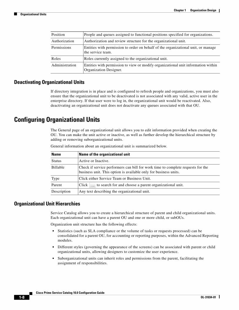
Configuring Organizational UnitsThe General page of an organizational unit allows you to edit information provided when creating the OU. You can make the unit active or inactive, as well as further develop the hierarchical structure by adding or removing suborganizational units.
General information about an organizational unit is summarized below.
Organizational Unit Hierarchies
Service Catalog allows you to create a hierarchical structure of parent and child organizational units. Each organizational unit can have a parent OU and one or more child, or subOUs.
Organization unit structure has the following effects:
• Statistics (such as SLA compliance or the volume of tasks or requests processed) can be consolidated for a parent OU, for accounting or reporting purposes, within the Advanced Reporting modules.
• Different styles (governing the appearance of the screens) can be associated with parent or child organizational units, allowing designers to customize the user experience.
• Suborganizational units can inherit roles and permissions from the parent, facilitating the assignment of responsibilities.
Position People and queues assigned to functional positions specified for organizations.
Authorization Authorization and review structure for the organizational unit.
Permissions Entities with permission to order on behalf of the organizational unit, or manage the service team.
Roles Roles currently assigned to the organizational unit.
Administration Entities with permission to view or modify organizational unit information within Organization Designer.
Name Name of the organizational unit
Status Active or Inactive.
Billable Check if service performers can bill for work time to complete requests for the business unit. This option is available only for business units.
Type Click either Service Team or Business Unit.
Parent Click to search for and choose a parent organizational unit.
Description Any text describing the organizational unit.
1-8Cisco Prime Service Catalog 10.0 Configuration Guide
OL-31034-01
Chapter 1 Organization DesignOrganizational Units
Suborganizational units, and therefore the members of that subOU, inherit all the roles and permissions assigned to its parent organizational unit. Because of this inheritance rule, you must make sure you set up role-based access carefully. An example would be using a bottom-up approach, in which the lowest child Organizational Unit is assigned the greatest number of roles, and therefore greatest responsibilities, and the higher up the parent Organizational Unit, the fewer roles are assigned.
Because you are adding suborganizational units to a parent, a helpful way to order your work is to:
1. Create the suborganizational units.
2. Create the parent organizational units.
3. Add the suborganizational units to the parent OU.
OU Members
You can specify the people who belong to an organizational unit. A person may be assigned to multiple OUs, but must have one Home OU. The process of associating an organizational unit with a person consists of the following:
1. Create the organizational unit.
2. Create the person.
3. Associate the person with the organizational unit – There are two ways you can create a person/OU relationship:
– Assign a person to an organizational unit – Adding a person via the Org Units page of the People component allows you to assign multiple people to an OU.
– Assign OUs to a person – Adding an organizational unit via the Members page of the People component allows you to assign multiple OUs to a particular person at once.
For service teams, you can specify which queues the team is responsible for. The process of associating an organizational unit with a person consists of the following:
1. Create the service team organizational unit.
2. Create the queue – When you create a service team, you need to create a queue for the service team to receive work. Before you can assign a queue to an OU, you must first create the queue.
3. Associate the queue with the organizational unit – There are two ways you can create a queue/OU relationship:
– Assign a queue to an organizational unit – Adding a queue within organizational unit information allows you to assign multiple queues to an OU.
– Assign OUs to a queue – Adding an organizational unit within a person's information allows you to assign multiple OUs to a particular person all at once.
1-9Cisco Prime Service Catalog 10.0 Configuration Guide
OL-31034-01
Chapter 1 Organization Design Organizational Units
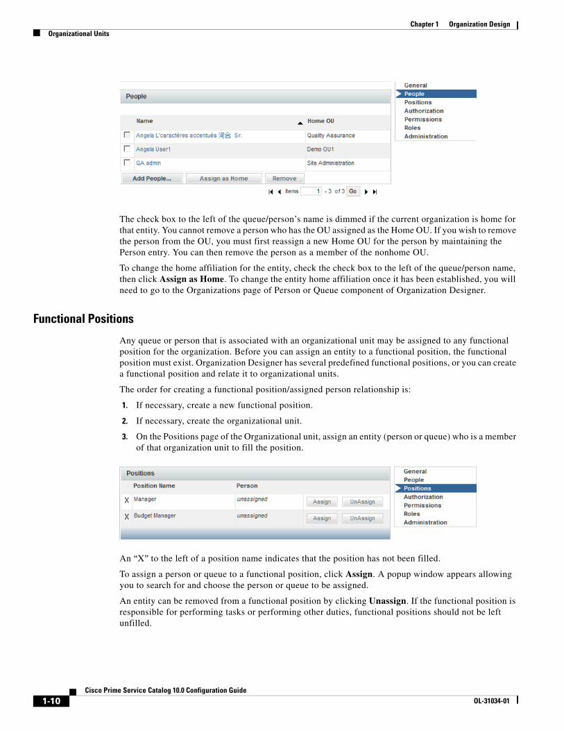
The check box to the left of the queue/person’s name is dimmed if the current organization is home for that entity. You cannot remove a person who has the OU assigned as the Home OU. If you wish to remove the person from the OU, you must first reassign a new Home OU for the person by maintaining the Person entry. You can then remove the person as a member of the nonhome OU.
To change the home affiliation for the entity, check the check box to the left of the queue/person name, then click Assign as Home. To change the entity home affiliation once it has been established, you will need to go to the Organizations page of Person or Queue component of Organization Designer.
Functional Positions
Any queue or person that is associated with an organizational unit may be assigned to any functional position for the organization. Before you can assign an entity to a functional position, the functional position must exist. Organization Designer has several predefined functional positions, or you can create a functional position and relate it to organizational units.
The order for creating a functional position/assigned person relationship is:
1. If necessary, create a new functional position.
2. If necessary, create the organizational unit.
3. On the Positions page of the Organizational unit, assign an entity (person or queue) who is a member of that organization unit to fill the position.
An “X” to the left of a position name indicates that the position has not been filled.
To assign a person or queue to a functional position, click Assign. A popup window appears allowing you to search for and choose the person or queue to be assigned.
An entity can be removed from a functional position by clicking Unassign. If the functional position is responsible for performing tasks or performing other duties, functional positions should not be left unfilled.
1-10Cisco Prime Service Catalog 10.0 Configuration Guide
OL-31034-01
Chapter 1 Organization DesignOrganizational Units
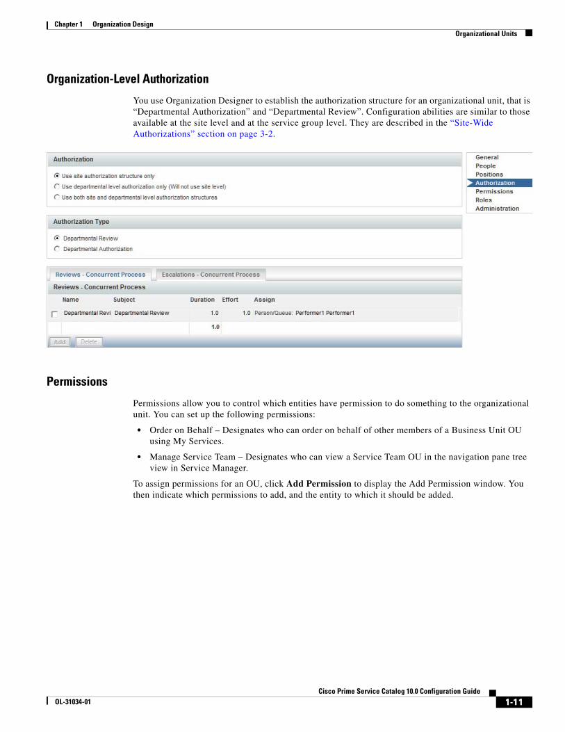
Organization-Level Authorization
You use Organization Designer to establish the authorization structure for an organizational unit, that is “Departmental Authorization” and “Departmental Review”. Configuration abilities are similar to those available at the site level and at the service group level. They are described in the “Site-Wide Authorizations” section on page 3-2.
Permissions
Permissions allow you to control which entities have permission to do something to the organizational unit. You can set up the following permissions:
• Order on Behalf – Designates who can order on behalf of other members of a Business Unit OU using My Services.
• Manage Service Team – Designates who can view a Service Team OU in the navigation pane tree view in Service Manager.
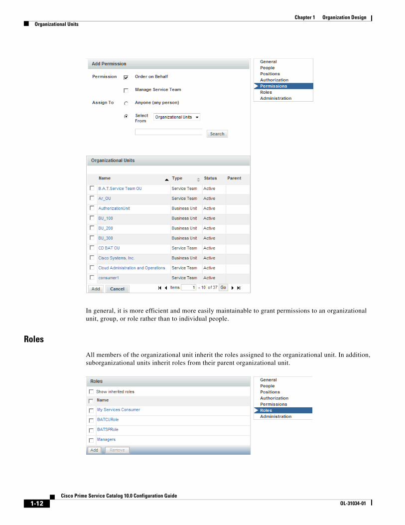
To assign permissions for an OU, click Add Permission to display the Add Permission window. You then indicate which permissions to add, and the entity to which it should be added.
1-11Cisco Prime Service Catalog 10.0 Configuration Guide
OL-31034-01
Chapter 1 Organization Design Organizational Units
In general, it is more efficient and more easily maintainable to grant permissions to an organizational unit, group, or role rather than to individual people.
Roles
All members of the organizational unit inherit the roles assigned to the organizational unit. In addition, suborganizational units inherit roles from their parent organizational unit.
1-12Cisco Prime Service Catalog 10.0 Configuration Guide
OL-31034-01

Chapter 1 Organization DesignOrganizational Units
The Show inherited roles option allows you to choose whether to show those roles inherited from a parent organizational unit. If not checked, only roles directly assigned to the organizational unit appear.
When an organization is created, it is automatically granted the My Services Consumer role. This allows any members of the organization (or suborganizations) to access My Services and to order any services for which they have been granted ordering permission. (Permission to order a service is granted via the service or service group.)
Any role defined in Request Center, both default roles provided by Service Catalog and custom roles created in each installation can be granted to an organization. For a detailed description of available roles and how to create a custom role, see the “Roles” section on page 1-32.
Users should typically not change aspects of the organization's definition that are refreshed via directory integration. If a change is needed, it must be applied to the contents of the directory that is the source of the data.
Any administrative privileges allowing changes to organizations are overridden by entity protections that are applied to an entity at any non home sites. See the Cisco Prime Service Catalog Designer Guide for more information on setting entity protection levels.
Administration
The Administration options show the permissions granted to users to read, write, or change rights for the current organization and allows administrators to assign these permissions to custom roles. The prebuilt roles grant the associated permissions to all organizations; adding a custom role or a specific person, OU or position, allows you to assign permission to read and write organizational data at the object level, that is, on an organization by organization basis.
Organization Designer does not “hide” selected OUs or queues using permissions, but prevents a user from reading or modifying a particular OU or queue. Entities that a user is not permitted to read or write are then indicated by italics, and will present a popup if that user tries to access that entity:
1-13Cisco Prime Service Catalog 10.0 Configuration Guide
OL-31034-01

Chapter 1 Organization Design Groups
You can either do this directly on the Administration page for the specific entity, or you could do this:
1. Create a role with the Access Organizational Unit Configuration and Access Queues Configuration capabilities.
2. Go to the Permissions page for the role.
3. Set the Read/Write permissions for the role using the wizard as follows:
a. OUs: All Service Teams of which user is a member
b. Queues: All queues associated with service teams of which user is a member
GroupsA group is an organizational and management tool to enhance your ability to organize services, allocate costs, assign permissions, and grant access rights at your site. Groups allow you to consolidate OUs and people with some shared characteristics into a single entity. Roles can then be assigned to a group, rather than to multiple organizations or people.
A group can have multiple subgroups. The subgroups inherit the members and roles assigned to the parent group.
Configuring GroupsGroup configuration includes the following pages.
Page Description
General General information about the group
Members Organizational units and people who are members of the group
1-14Cisco Prime Service Catalog 10.0 Configuration Guide
OL-31034-01
Chapter 1 Organization DesignGroups
Configuring General Group Information
The General portion of group information allows you to edit information provided when creating the group. You can make the group active or inactive, as well as further develop the hierarchical structure by adding or removing subgroups.
Adding or Removing Subgroups
Subgroups allow you to create a hierarchical structure of parent and child groups. Each group can have both a parent group and one or more child, or subgroups. subgroups are grouped within a parent group.
Subgroups, and therefore the members of that subgroup, inherit all the roles and permissions assigned to its parent group. Because of this inheritance rule, you must make sure you set up your role and permission system carefully. An example would be using a bottom-up approach, in which the lowest child group is assigned the greatest amount of roles, and therefore greatest responsibilities, and the higher up the parent group, the fewer roles assigned to it.
Because you are adding subgroups to a parent, a helpful way to order your work is to:
1. Create the subgroups.
2. Create the parent groups.
3. Add the subgroups to the parent group.
Members
Group members consist of a combination of organizational units and individual people. You can specify the people and organizational units that belong to the group. The process of associating a group with a person or OU consists of the following:
1. Create the group.
2. Create the person or organizational unit before you can assign a person or OU to a group, you must first create the person or create the OU within the system.
3. Associate the person or OU with the group.
Roles Roles assigned to the group
Administration Access control within Organization Designer
1-15Cisco Prime Service Catalog 10.0 Configuration Guide
OL-31034-01

Chapter 1 Organization Design Groups
A member may be removed from the group at any time by checking the check box to the left of the member name and then clicking Remove.
Roles
When assigning roles to a group, all members of the group inherit the role. In addition, subgroups inherit roles from their parent group. The Show inherited roles option allows you to choose whether to show those roles inherited from a parent group. If not checked, only roles directly assigned to the group appear.
Before you can assign a role to a group, you must first make sure the role exists. Service Catalog provides several preconfigured roles for your use, or you can create a new role to fit your company needs.
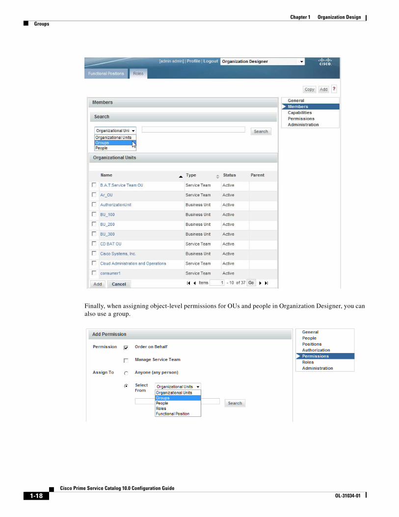
Using Groups in Service DesignPermissions can be assigned to groups, rather than being assigned to individual people or to organizations. It is a way to group disparate people or organizations and give them the same permissions.
Within Service Designer, a Group can be used directly when granting object-level permissions related to service groups, services and form groups. Those object-level permissions are:
Groups can also be used as an Additional Participant when assigning Access Control for dictionaries.
Object Permission
Service Group Design services and change data in this service group
Service Group View services and other information in this service group
Service Group Order service group services
Service Group Assign rights
Service Order service
Active Form Group View forms
Active Form Group Design forms
1-16Cisco Prime Service Catalog 10.0 Configuration Guide
OL-31034-01

Chapter 1 Organization DesignGroups
In addition, because a group can be a member of a role, you can also use groups indirectly wherever you can use a role. For instance, conditional rules include a User Role and Customer Role condition type. In this case, you could create a group, make it a member of a role, and use it in defining conditions for conditional rules.
Within Organization Designer, anyplace where you are working with roles, you can use a group to collect together the people/OUs to whom you wish to grant that role.
1-17Cisco Prime Service Catalog 10.0 Configuration Guide
OL-31034-01
Chapter 1 Organization Design Groups
Finally, when assigning object-level permissions for OUs and people in Organization Designer, you can also use a group.
1-18Cisco Prime Service Catalog 10.0 Configuration Guide
OL-31034-01
Chapter 1 Organization DesignQueues
QueuesA queue is a repository, or “Inbox,” for tasks that need to be performed. Work is assigned to queues so that tasks are not dependent on any one individual.
After creating a queue, you use the Access Queue object-level permission to specify who can access the tasks sent to the queue. People are not “members” of a queue. They simply staff a queue by having permission to access it. Anyone with access to the queue can perform the tasks assigned to the queue. Members of the service team that is the Home OU for a queue automatically receive the Access Queue permission.
Service Catalog comes with one preconfigured queue, the Default Service Delivery Queue. If a task is not assigned to a task performer, or if a namespace used to dynamically assign a task does not evaluate to a valid queue, the task is placed in the Default Service Delivery Queue.
Defining a queue consists of entering the information on the Queue pages summarized below.
Tips for Working with Queues • Queues are mapped to service teams. Only use service teams as the Home OU for queues.
• Every service delivery task should be mapped to a queue for execution of tasks.
• Ensure that queue calendars and time zones are set correctly. Request Center calculates due dates and times for tasks based on the calendar and time zone settings of queues to which the tasks are assigned.
Configuring Queues
Configuring General Queue Information
The General page of a queue allows you to edit information provided when creating the queue. You can deem the queue active or inactive, as well as set the time zone for the queue.
Page Description
General General information about the queue
Org Units Organizational units assigned to the queue
Contact Contact phone numbers and email address
Calendar Work hours and days, as well as holidays
Permissions Assign who has permission to access queue information within Service Manager
Administration Entities with permission to view or modify queue information within Organization Designer
1-19Cisco Prime Service Catalog 10.0 Configuration Guide
OL-31034-01

Chapter 1 Organization Design Queues
The queue's general properties are summarized below.
Queue Organizational Units
You can specify the service teams assigned to a queue. When you create a new queue, you must assign a default, or Home, organizational unit. Though several service team OUs can be responsible for a queue, a queue can only have one Home OU. To make an association between an organizational units and queue, use one of the following methods:
• Open the service team information and assign queues.
• Open the queue and assign service teams.
Queue Contact
Administrators may refer to queue contact information if a problem arises with delivery of tasks assigned to a particular queue. Different contact types (email, phone numbers, and so on) are provided. Multiple email addresses can be entered in the Email field in Queue Contact. The email addresses need to be delimited by a semicolon (with no spaces); for example, [email protected];[email protected].
Name Name of the new queue. The name may be identical to the name of the service team (organizational unit) is the Home OU for the queue. When the queue name appears, it will have “Queue” appended to the specified name. The maximum length of a queue name is 100 characters. The name can contain alphanumeric characters and the underscore; it should not contain special characters such as the ampersand (&).
Time Zone Time zone for the queue's primary location. The queue time zone, as well as calendar, is critical for estimating the due dates of tasks assigned to the queue.
Notes Any text describing the queue.
1-20Cisco Prime Service Catalog 10.0 Configuration Guide
OL-31034-01

Chapter 1 Organization DesignQueues
All contact types except Email can be deleted from the queue contact information.
Queue Calendar
Use the Calendar page to set the work hours and days, and assign nonwork days and holidays. Calendar information is used to compute due dates for tasks and services according to the queue’s work hours.
For a new queue, the work schedule defaults to five days a week, from 8am to 6pm, in the time zone specified for the queue (specified on the General page), as shown in the “Time Schedule” portion of the Calendar page. You may make any necessary changes to the work hours.
• Enter times for the From and To fields, using a HH:MM AM/PM format.
• Enter the same time in both the From and To fields, for example 12:00 AM and 12:00 AM, to designate days that you do not work.
• Click Update to save changes.
You can use the “Additional Dates” portion of the Calendar page to tag a specific day as either a holiday or working day. Click Add New to add a new date. Enter the date by choosing from the calendar icon ( ), specify a Name for the date (for internal documentation), designate the type as either a Holiday or Working Day, and then click Update. These additional dates will also be taken into account when computing task and service due dates.
Queue Permissions
Permissions allow you to control who or what has permission to access the queue. Accessing the queue allows the user to see and perform tasks for a particular queue within Service Manager.
1-21Cisco Prime Service Catalog 10.0 Configuration Guide
OL-31034-01

Chapter 1 Organization Design People
By default, some preconfigured roles automatically can access any queue. Consequently, any entity (person, organization, or group) granted one of those roles is able to access the queue. In addition, members of any OUs associated with the queue automatically are allowed to access the queue.
PeoplePeople are all the individuals who either receive services via My Services or provide services via Service Manager, as well as all the administrators, managers, and users of all other application modules.
You must set up all individuals who are system users, whether they are within or external to your organization. The following two statements are important to remember:
• A person is a member of one or more Organizational Units.
• A person can only be “Home” in one OU.
Creating New PeopleService Catalog provides three mechanisms for adding people:
• Organization Designer allows administrators to create a person interactively, using the pages described in this section.
• The Import Person event in Directory Integration can create a person and his/her home OU. For more information, see the Cisco Prime Service Catalog Integration Guide.
• The Directory Task available in the service workflow (delivery plan) can create a person based on service form data. For more information, see the Cisco Prime Service Catalog Designer Guide.
No matter how a person is created, their personnel information can be maintained using Organization Designer.
When creating a new person, you must assign a default, or Home, organizational unit to the person. Therefore make sure you create the organizational unit before you create the new person.
To add a new person the following fields are required (marked with an asterisk (*)):
First Name First name of the person.
Last Name Last name of the person.
Email Contact email address.
1-22Cisco Prime Service Catalog 10.0 Configuration Guide
OL-31034-01

Chapter 1 Organization DesignPeople
Configuring PeopleThe following pages allow you to configure information about people:
General Person Information
The General page of a person's information allows you to edit the following information:
Time Zone The time zone associated with the person's primary address. If not provided, the default server time zone is used.
Language The language that appears on the user interface for the person. If not provided, English is used.
Home OU The person's default organizational unit. It is recommended that you choose a business unit as a person's Home OU, rather than a service team.
Login A unique login identifier.
Password A password used to log on to the system. If using Organization Designer, reenter the password to confirm. Any character in the character set supported by the application can be used in the password.
Page Description
General General information about the person.
Org Units Organizational units to which the person belongs.
Address Company or personal address information.
Contact Contact phone numbers and email address.
Extensions Extended information about a person.
Calendar Work hours and days, as well as holidays.
Permissions Entities with permission to order on behalf of the person, or assign an authorization delegate.
Roles Roles available to the person.
Administration Entities with permission to view or modify information about a particular person within Organization Designer.
Title Abbreviation used when addressing correspondence to the person; Ms. or Mr., for example.
First Name First name of the person.
Last Name Last name of the person.
Status Active or Inactive.
SSN Social security number.
Birth Date Date of birth.
Hire Date Person's hire date.
Time Zone The time zone associated with the person's primary address. This is used to calculate and display the proper due dates for tasks and services according to the person's time zone.
1-23Cisco Prime Service Catalog 10.0 Configuration Guide
OL-31034-01

Chapter 1 Organization Design People
Assigning Organizational Units to People
When you create a person, you must assign a default, or Home, organizational unit to the person. Though a person can have only one Home OU, they can be a member of several organizational units. To make an organizational units and people association, use one of the following methods:
• Open the organizational unit and assign people.
• Open the Org Units page of an individual person's information and assign organizational units to the person, as shown below.
These methods are functionally equivalent, so choose whichever one is more convenient.
Language The language that appears on the user interface for the person.
Employee Code Company-derived employee code, if any.
Supervisor The supervisor for the employee. This is used in “supervisor” tasks such as certain authorizations. You use Service Designer to create these tasks.
Notes Any additional descriptive information about the person.
Login A unique login identifier.
Password The password used to log on to the system.
Confirm Password Reenter the password.
1-24Cisco Prime Service Catalog 10.0 Configuration Guide
OL-31034-01

Chapter 1 Organization DesignPeople
In addition, people may be assigned to organizational units via the Org Units attribute mapping in Directory Integration.
Assigning an organization as the person's home OU automatically removes the home OU designation from the previous home.
Address Information
You can enter company and personal addresses, as well as specific location information, for each person.
Having valid address information for a person may be critical to ensure:
• Task performers can find the person when a service needs to be performed in person, for example, changing the hardware configuration of a workstation
• Delivery plans can use expressions that are dynamically evaluated to route work to a queue that serves the area where the service requestor is located. Such “location-based queues” are common in geographical distributed organizations.
Contact Information
You can enter multiple means of contacting a person, each one identified by a contact type, such as email, telephone, and so on.
1-25Cisco Prime Service Catalog 10.0 Configuration Guide
OL-31034-01
Chapter 1 Organization Design People
• The email address specified when you create a person displays as the first contact. You can change this email address, but you cannot delete it.
• All contact types except email address can be freely added to and deleted from the person's contact information.
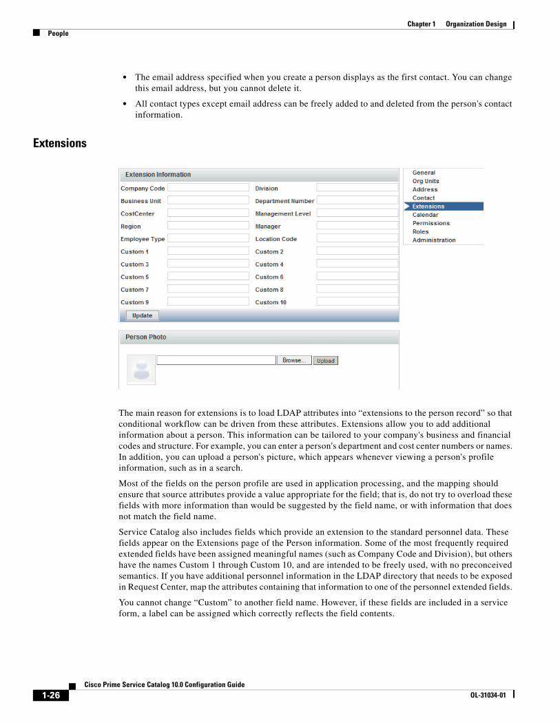
Extensions
The main reason for extensions is to load LDAP attributes into “extensions to the person record” so that conditional workflow can be driven from these attributes. Extensions allow you to add additional information about a person. This information can be tailored to your company's business and financial codes and structure. For example, you can enter a person's department and cost center numbers or names. In addition, you can upload a person's picture, which appears whenever viewing a person's profile information, such as in a search.
Most of the fields on the person profile are used in application processing, and the mapping should ensure that source attributes provide a value appropriate for the field; that is, do not try to overload these fields with more information than would be suggested by the field name, or with information that does not match the field name.
Service Catalog also includes fields which provide an extension to the standard personnel data. These fields appear on the Extensions page of the Person information. Some of the most frequently required extended fields have been assigned meaningful names (such as Company Code and Division), but others have the names Custom 1 through Custom 10, and are intended to be freely used, with no preconceived semantics. If you have additional personnel information in the LDAP directory that needs to be exposed in Request Center, map the attributes containing that information to one of the personnel extended fields.
You cannot change “Custom” to another field name. However, if these fields are included in a service form, a label can be assigned which correctly reflects the field contents.
1-26Cisco Prime Service Catalog 10.0 Configuration Guide
OL-31034-01
Chapter 1 Organization DesignPeople
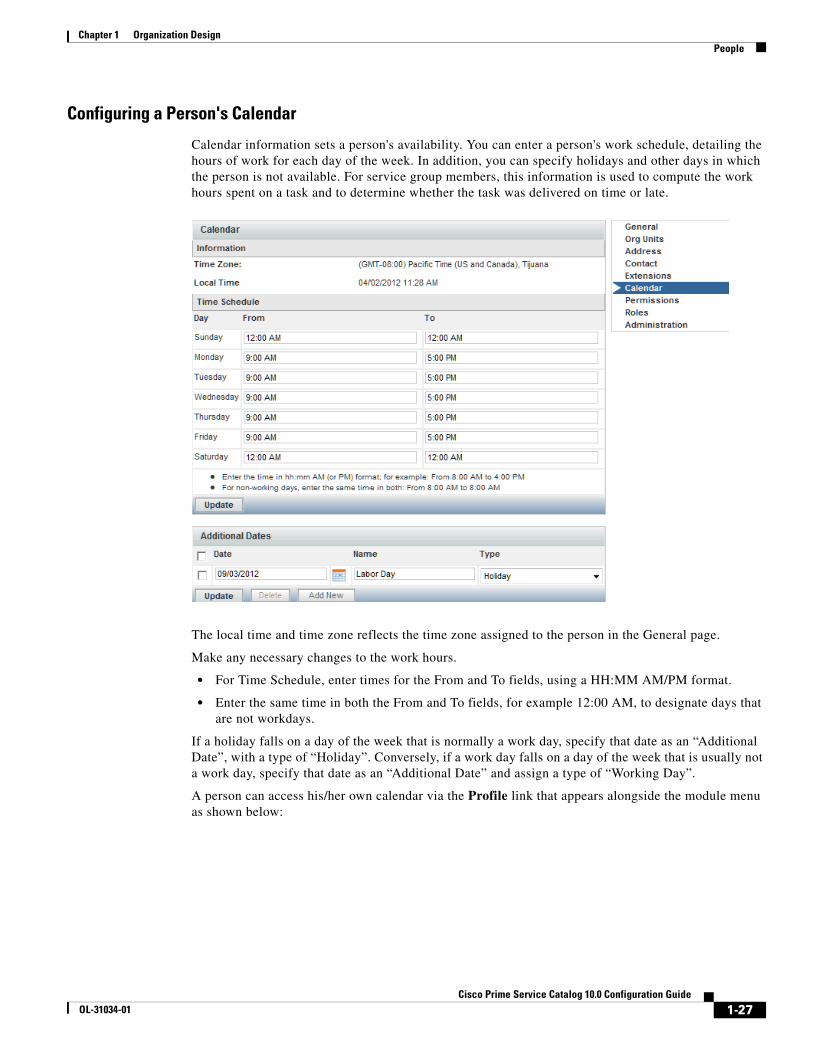
Configuring a Person's Calendar
Calendar information sets a person's availability. You can enter a person's work schedule, detailing the hours of work for each day of the week. In addition, you can specify holidays and other days in which the person is not available. For service group members, this information is used to compute the work hours spent on a task and to determine whether the task was delivered on time or late.
The local time and time zone reflects the time zone assigned to the person in the General page.
Make any necessary changes to the work hours.
• For Time Schedule, enter times for the From and To fields, using a HH:MM AM/PM format.
• Enter the same time in both the From and To fields, for example 12:00 AM, to designate days that are not workdays.
If a holiday falls on a day of the week that is normally a work day, specify that date as an “Additional Date”, with a type of “Holiday”. Conversely, if a work day falls on a day of the week that is usually not a work day, specify that date as an “Additional Date” and assign a type of “Working Day”.
A person can access his/her own calendar via the Profile link that appears alongside the module menu as shown below:
1-27Cisco Prime Service Catalog 10.0 Configuration Guide
OL-31034-01

Chapter 1 Organization Design People
Assigning Permissions to a Person
Permissions define an object’s capability to affect a chosen person. These objects can be organizational units, groups, other people, roles, and functional positions. For people, you can set up permissions to define who can order on behalf of the chosen person:
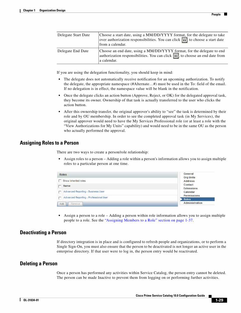
The Permissions page also designates the Authorization Delegate for the chosen person in the event that an authorizer cannot fulfill authorization duties, for example if the authorizer is on vacation. The delegate can perform authorizations for the person during the time period specified using the Delegation Start Date and Delegation End Date fields.
A person may assign their own Authorization Delegate using the Preferences page of the Profile option. Since delegates may be designated many times, for different periods, it is recommended that individuals be responsible for designating their own delegates, rather than using Organization Designer to do this.
To assign a person's Authorization Delegate supply the information summarized below.
Authorization Delegate Click Select Person to search for and choose the person responsible for authorizations in the event that the original authorizer is unavailable.
1-28Cisco Prime Service Catalog 10.0 Configuration Guide
OL-31034-01
Chapter 1 Organization DesignPeople
If you are using the delegation functionality, you should keep in mind:
• The delegate does not automatically receive notification for an upcoming authorization. To notify the delegate, the appropriate namespace (#Alternate…#) must be used in the To: field of the email. If no delegation is in effect, the namespace value will be blank in the notification.
• Once the delegate clicks an action button (Approve, Reject, or OK) for the delegated approval task, they become its owner. Ownership of that task is actually transferred to the user who clicks the action button.
• After this ownership transfer, the original approver's ability to “see” the task is determined by their role and by OU membership. In order to see the completed approval task (in My Services), the original approver would need to have the My Services Professional role (or at least a role with the “View Authorizations for My Units” capability) and would need to be in the same OU as the person who actually performed the approval.
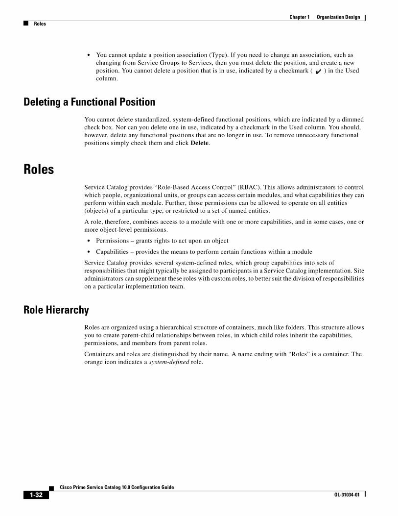
Assigning Roles to a Person
There are two ways to create a person/role relationship:
• Assign roles to a person – Adding a role within a person's information allows you to assign multiple roles to a particular person at one time.
• Assign a person to a role – Adding a person within role information allows you to assign multiple people to a role. See the “Assigning Members to a Role” section on page 1-37.
Deactivating a Person
If directory integration is in place and is configured to refresh people and organizations, or to perform a Single Sign-On, you must also ensure that the person to be deactivated is not longer an active user in the enterprise directory. If that user were to log in, the person entry would be reactivated.
Deleting a Person
Once a person has performed any activities within Service Catalog, the person entry cannot be deleted. The person can be made Inactive to prevent them from logging on or performing further activities.
Delegate Start Date Choose a start date, using a MM/DD/YYYY format, for the delegate to take over authorization responsibilities. You can click to choose a start date from a calendar.
Delegate End Date Choose an end date, using a MM/DD/YYYY format, for the delegate to end authorization responsibilities. You can click to choose an end date from a calendar.
1-29Cisco Prime Service Catalog 10.0 Configuration Guide
OL-31034-01

Chapter 1 Organization Design Functional Positions
Functional PositionsFunctional positions can add flexibility to configuring a service's delivery plan and assigning responsibilities for various aspects of the Service Catalog application. A task within the system can be assigned to a functional position. A person, queue or role can then be assigned to fill that functional position. The functional position can be referenced in tasks (assigned as a task performer) or in namespaces (included in an email sent to the appropriate person or people.)
Functional positions can be associated with one of the four entity types:
• Organizational Units
• Service Groups
• Services
• Accounts
Service Catalog provides several standard functional positions, which cannot be modified. In the illustration below, the check boxes to the left of the system-defined functional positions are dimmed, indicating that these positions cannot be deleted or updated. The “Manager” and “Tester” positions were created at this site.
Functional positions associated with each type of entity appear on the Positions page for organizational units in Organization Designer, or on the General tab for services or service groups in Service Designer. For example, with just the standard functional positions associated with an organization, the account functional positions page for maintaining Organizations would look like this:
1-30Cisco Prime Service Catalog 10.0 Configuration Guide
OL-31034-01

Chapter 1 Organization DesignFunctional Positions
Creating a New Functional PositionIf the system-defined functional positions do not meet your company's requirements, you can create new functional positions. To add a new functional position:
Step 1 Click Add on the Functional Position page, a new line will appear at the bottom of the list of positions.
Step 2 Enter a name for the functional position and choose its Type from the drop-down menu on the right.
Step 3 Click Update to save the new functional position. The name cannot be the same name as a previously defined functional position even if it has a different Type. Also, the name should not contain spaces, even though this is permitted. A name with embedded spaces cannot be used as a namespace variable.
Step 4 By choosing the “Type”, you associate the position with an organizational unit, service group, or service. New functional positions associated with each type of entity are automatically added to the Positions page for organizational units in Organization Designer, or on the General tab for services or service groups in Service Designer.
Once the functional position has been defined, you may assign a person to the position through the Positions page for the organizational unit in Organization Designer, or on the General tab for the service or service group in Service Designer.
Modifying a Functional PositionWhen attempting to update a functional position, keep in mind:
• The standard positions display a disabled (dimmed) check box next to the position name and cannot be deleted, even if they are not in use.
• You can only update a created functional position name.
1-31Cisco Prime Service Catalog 10.0 Configuration Guide
OL-31034-01
Chapter 1 Organization Design Roles
• You cannot update a position association (Type). If you need to change an association, such as changing from Service Groups to Services, then you must delete the position, and create a new position. You cannot delete a position that is in use, indicated by a checkmark ( ) in the Used column.
Deleting a Functional PositionYou cannot delete standardized, system-defined functional positions, which are indicated by a dimmed check box. Nor can you delete one in use, indicated by a checkmark in the Used column. You should, however, delete any functional positions that are no longer in use. To remove unnecessary functional positions simply check them and click Delete.
RolesService Catalog provides “Role-Based Access Control” (RBAC). This allows administrators to control which people, organizational units, or groups can access certain modules, and what capabilities they can perform within each module. Further, those permissions can be allowed to operate on all entities (objects) of a particular type, or restricted to a set of named entities.
A role, therefore, combines access to a module with one or more capabilities, and in some cases, one or more object-level permissions.
• Permissions – grants rights to act upon an object
• Capabilities – provides the means to perform certain functions within a module
Service Catalog provides several system-defined roles, which group capabilities into sets of responsibilities that might typically be assigned to participants in a Service Catalog implementation. Site administrators can supplement these roles with custom roles, to better suit the division of responsibilities on a particular implementation team.
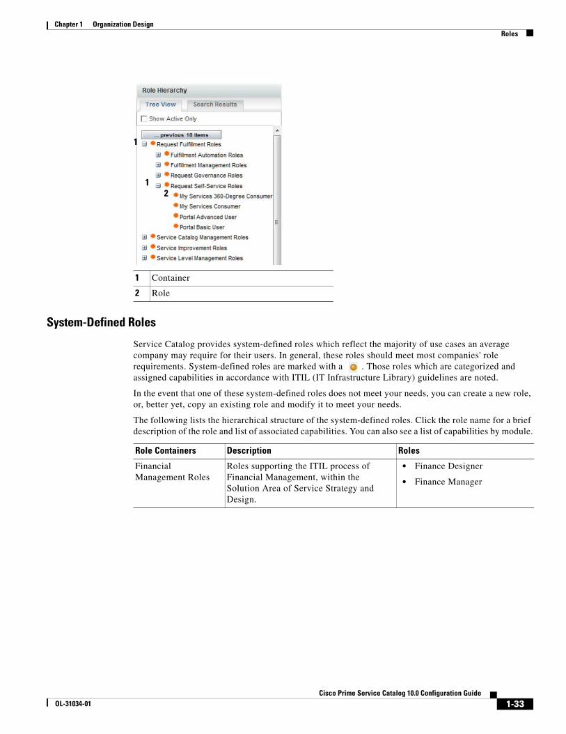
Role HierarchyRoles are organized using a hierarchical structure of containers, much like folders. This structure allows you to create parent-child relationships between roles, in which child roles inherit the capabilities, permissions, and members from parent roles.
Containers and roles are distinguished by their name. A name ending with “Roles” is a container. The orange icon indicates a system-defined role.
1-32Cisco Prime Service Catalog 10.0 Configuration Guide
OL-31034-01
Chapter 1 Organization DesignRoles
System-Defined Roles
Service Catalog provides system-defined roles which reflect the majority of use cases an average company may require for their users. In general, these roles should meet most companies' role requirements. System-defined roles are marked with a . Those roles which are categorized and assigned capabilities in accordance with ITIL (IT Infrastructure Library) guidelines are noted.
In the event that one of these system-defined roles does not meet your needs, you can create a new role, or, better yet, copy an existing role and modify it to meet your needs.
The following lists the hierarchical structure of the system-defined roles. Click the role name for a brief description of the role and list of associated capabilities. You can also see a list of capabilities by module.
1 Container
2 Role
12
1
Role Containers Description Roles
Financial Management Roles
Roles supporting the ITIL process of Financial Management, within the Solution Area of Service Strategy and Design.
• Finance Designer
• Finance Manager
1-33Cisco Prime Service Catalog 10.0 Configuration Guide
OL-31034-01

Chapter 1 Organization Design Roles
Request Fulfillment Roles
Roles supporting the ITIL process of Request Fulfillment, within the Solution Area of Service Operations, including Request Self-Service, Request Governance, and the management and automation of fulfillment activities.
Subcontainers Description
Fulfillment Automation Roles
Roles supporting the automation of service request fulfillment and delivery.
• Integration Administration
• Integration Specialist
Fulfillment Management Roles
Roles supporting the fulfillment of service requests.
• Service Manager
• Service Performer
• Service Team Administrator
• Service Team Manager
Request Governance Roles
Roles supporting the governance of service requests.
• My Services 360-Degree Professional
• My Services Professional
• Portal Professional User
Request Self-Service Roles
Roles supporting the initiation and tracking of service requests.
• My Services 360-Degree Consumer
• My Services Consumer
• Portal Advanced User
• Portal Basic User
Service Catalog Management Roles
Roles supporting the ITIL area of Service Catalog Management, within the Solution Area of Service Strategy and Design.
• Catalog Designer and Administrator
• Catalog Presentation Owner
• Catalog Publisher
• Distributed Catalog Manager
• Distributed Service Component Designer
• Distributed Service Designer
• Distributed Service Request Designer
• Interactive Form Specialist
Service Level Management Roles
Roles supporting the ITIL process of Service Level Management, within the Solution Area of Service Strategy and Design.
• Service Level Designer
• Service Level Manager
Role Containers Description Roles
1-34Cisco Prime Service Catalog 10.0 Configuration Guide
OL-31034-01
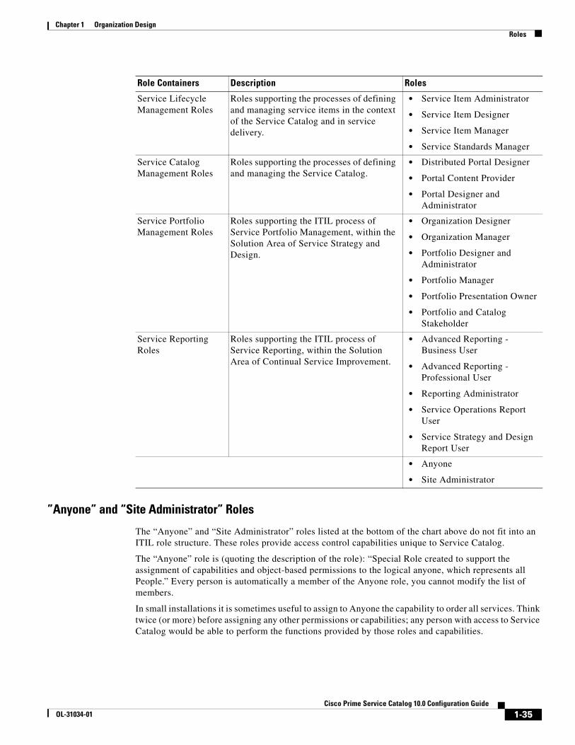
Chapter 1 Organization DesignRoles
”Anyone” and “Site Administrator” Roles
The “Anyone” and “Site Administrator” roles listed at the bottom of the chart above do not fit into an ITIL role structure. These roles provide access control capabilities unique to Service Catalog.
The “Anyone” role is (quoting the description of the role): “Special Role created to support the assignment of capabilities and object-based permissions to the logical anyone, which represents all People.” Every person is automatically a member of the Anyone role, you cannot modify the list of members.
In small installations it is sometimes useful to assign to Anyone the capability to order all services. Think twice (or more) before assigning any other permissions or capabilities; any person with access to Service Catalog would be able to perform the functions provided by those roles and capabilities.
Service Lifecycle Management Roles
Roles supporting the processes of defining and managing service items in the context of the Service Catalog and in service delivery.
• Service Item Administrator
• Service Item Designer
• Service Item Manager
• Service Standards Manager
Service Catalog Management Roles
Roles supporting the processes of defining and managing the Service Catalog.
• Distributed Portal Designer
• Portal Content Provider
• Portal Designer and Administrator
Service Portfolio Management Roles
Roles supporting the ITIL process of Service Portfolio Management, within the Solution Area of Service Strategy and Design.
• Organization Designer
• Organization Manager
• Portfolio Designer and Administrator
• Portfolio Manager
• Portfolio Presentation Owner
• Portfolio and Catalog Stakeholder
Service Reporting Roles
Roles supporting the ITIL process of Service Reporting, within the Solution Area of Continual Service Improvement.
• Advanced Reporting - Business User
• Advanced Reporting - Professional User
• Reporting Administrator
• Service Operations Report User
• Service Strategy and Design Report User
• Anyone
• Site Administrator
Role Containers Description Roles
1-35Cisco Prime Service Catalog 10.0 Configuration Guide
OL-31034-01

Chapter 1 Organization Design Roles
The “Site Administrator” role, quoting from the role description, is a “Role automatically assigned to any user who is a member of the Site Administration organizational unit; provides all capabilities and permissions within Request Center and Demand Center.” The “admin” user is automatically a member of the Site Administrator role. Other members should be assigned sparingly, because of the power conferred by the role.
Searching for RolesYou can search for a role by typing all or part of its name in the Search box on the Roles tab.
In the Search Results list, click the Item Hierarchy icon to view its exact location in the roles Tree View.
In the example above, “My Services Consumer” was entered into the Search field. The role was found and listed on the Search Results tab. You can see, by clicking the hierarchy icon, that this role resides in the Request Fulfillment Roles container, which resides in the Request Self-Service Roles container.
Click the role name to view general details such as the name and description, the entities that have been assigned to this role, included capabilities, object-level permissions, and to configure which entities have access to this role.
Configuring Roles
You use the Roles tab to search for and to view, create, modify, deactivate, or delete roles. Once you locate the role you wish to work with, there are five sections with which to become familiar:
General General information about the role, including the role name and description, its place in the role hierarchy, as well as its status (Active or Inactive).
Members People, groups, and organizational units assigned this role.
Capabilities Capabilities included in a role. You cannot add or delete capabilities in a system-defined role, although you can add subroles/child roles to a system-defined role.
1-36Cisco Prime Service Catalog 10.0 Configuration Guide
OL-31034-01

Chapter 1 Organization DesignRoles
Assigning Members to a Role
Members of a role consist of individual people, groups, and organizational units that have been assigned the role. If groups or organizational units are assigned, all members of the group or unit inherit the role. In addition, suborganizational units and subgroups inherit roles from their parent. The Show inheriting members option allows you to choose whether to show those members who have inherited the role from a parent organizational unit or group. If not checked, only organizational units and groups directly assigned to the role appear.
Before you can assign person, group, or organizational unit to the role, you must first make sure the entity exists.
There are two ways to create a role/member association:
• Go to the individual person, group, or organizational unit, and assign the role.
• Go to the role and add members.
Permissions Object-level permissions, if any, for the role. Not every module contains objects with object-level permissions. You can choose to select all objects or specific objects.
Administration Entities with permission to view or modify role information.
1-37Cisco Prime Service Catalog 10.0 Configuration Guide
OL-31034-01

Chapter 1 Organization Design Roles
The screen above is for the My Services Consumer role, which is automatically granted to every OU, and by inheritance, to every person in every OU.
Roles with Object-Level PermissionsNot every module contains objects with object-level permissions. Thus, not every role has object-level permissions assigned. An example of a role that does include object-level permissions is the “Service Team Administrator” role, which resides in the Request Fulfillment Roles > Fulfillment Management Roles container. The “Service Team Administrator” role includes capabilities across two modules:
1-38Cisco Prime Service Catalog 10.0 Configuration Guide
OL-31034-01

Chapter 1 Organization DesignRoles
If the purpose of this role is to enable the full range of management actions in Service Manager and the ability to create and manage service teams and queues in Organization Designer, then this role must grant object-level permissions to Organizational Units, People, and Queues, as shown below.
Custom RolesOrganization Designer provides a large number of predefined roles. These roles should be suitable for most use cases an average company may encounter for their users. If, however, you need additional roles, you can create custom roles by either creating a new role from scratch or copying an existing role and modifying it to meet your needs.
Because of the numerous combinations of capabilities and permissions available, keeping track of these combinations can be a challenge. Therefore, you should create a new role by identifying a system-defined role that has most or all of the capabilities you need. You should not use a system-defined role with more capabilities than you need is because you cannot remove capabilities from a child; it inherits all of the capabilities of its parent.
Step 1 Create this role by doing one of the following:
1-39Cisco Prime Service Catalog 10.0 Configuration Guide
OL-31034-01

Chapter 1 Organization Design Roles
• Create a new role.
• Copy a similar role to use as a template for a new role.
Step 2 Make the user-defined role a child of a system-defined role.
Step 3 Define the new role by adding capabilities and permissions as needed.
Step 4 Assign members to the role.
General Role Information
Enter the following information:
For custom roles, the General page allows you to edit information provided when the role was created. You can assign a parent role, set the role to be active or inactive, or add to the roles description, logging any changes as they occur. You can also develop the hierarchical structure by adding or removing sub roles.
Role Hierarchies
Sub roles allow you to create a hierarchical structure of parent and child roles. Each role can have both a parent role and one or more child, or sub roles. Only custom roles can be used when creating a sub role hierarchy. The hierarchical structure of system-defined roles cannot be changed.
Sub roles, and therefore the members of that sub role, inherit all the capabilities assigned to its parent role. Because of this inheritance rule, you must make sure you set up your role system carefully.
You can create a parent/child relationship using two methods:
Name Name of the new role.
Parent Click the ellipses to search for and choose the system-defined parent role that most closely resembles the new role you wish to create.
Description Any text describing the new role.
1-40Cisco Prime Service Catalog 10.0 Configuration Guide
OL-31034-01

Chapter 1 Organization DesignRoles
• Assign a parent role on the General page.
• Assign child, or sub roles to the parent.
Assigning Role Capabilities
A “capability” is the ability to perform certain functions within Service Catalog. It is critical to review the capabilities that are available and how they are combined in the predefined roles in order to be able to assign the predefined roles to appropriate users and potentially to recognize the need to create a custom role.
The easiest way to review the available capabilities online is to “pretend” to create a custom role, click Add Capabilities, and browse through the list that appears. Capabilities are divided by module, since each capability confers rights to perform functions within a particular module.
Note To disable the access provided to the roles, remove the role from the selected person or remove the capabilities that was assigned.
Capabilities for each module are summarized below.
Capabilities for My Services, Service Catalog, and Order Management
My Services capabilities pertain to the abilities to order services; view requisitions; and access tabs and links available in the My Services, Service Catalog, and Order Management module.
Capability Description
View Requisitions This capability controls whether the user can see the “Requisitions” link and portlet. Users with this capability can also drill down to Requisition details and track the current status.
See Requisitions for My Business Units
Users with this capability can see all requisitions for their business units in the My Stuff view.
View and Perform Authorizations
This capability controls whether users can see the “Authorizations” link in the top navigation bar.
See Authorizations for My Business Units
Users with this capability can see all authorizations for their business unit in the Authorizations view.
Order on Behalf Users will see the Order on Behalf link in the top level navigation bar if you they are using the My Services module. Simply having any Order On Behalf object permission will also cause the Order on Behalf link to appear.
Order My Services for Others
Users can order any service they have ordering permissions for on behalf of other users, in addition to the services that those other users can order for themselves.
View KPIs The KPI portlet appears in the My Services, My Services Executive, Relationship Manager, and Service Level Manager home pages (this capability is effective only if the Show KPI Portlet global setting is turned On).
Browse for Services This capability controls if the user can see the Browse Services portlet.
Search for Services This capability controls the Search Services portlet.
1-41Cisco Prime Service Catalog 10.0 Configuration Guide
OL-31034-01

Chapter 1 Organization Design Roles
Capabilities for Service Designer
The Service Designer capabilities allow different sets of users to work on different aspects of a service definition. Coupled with the ability to assign permissions to different sets of users to work on different sets of services and service groups, this provides robust support for a distributed development environment
Most of these same capabilities govern the equivalent functionality in the Service Catalog and Order Management modules. The only exception is "View KPIs" which is not available outside of My Services. There are also some differences in how some of these capabilities work in Service Catalog. Users who have chosen Service Catalog as their catalog view will have implicit capabilities for service browse and search, and use the "Order for others" action buttons to order services on behalf of another person. .
Order Services This capability controls whether the user receives the “Order” link next to services that are orderable.
Copy Requisitions This capability controls if the user sees the “Copy Requisition” link in the top navigation bar and all associated functionality for Copy Requisitions.
Manage Profile This capability controls whether users can manage their profile which is available via the “Profile” link.
Acess Service Item Instance This capability enables the user with this role to view the My Stuff section in Service Catalog module. users who use My Services will be able to access “Service Items” tab in My Services module.
Capability Description
Access Services This capability grants access to the Service Catalog option within Service Designer. Any user with this capability has access to all of the services in any of the service groups to which he has the “Design Services…” or “View Services…” permission. This capability provides access to all tabs within the service definition.
Access Service Presentation
This capability grants access only to the General, Offer, and Presentation tabs for a service. A user with this capability has access to those tabs on all services in any of the service groups to which he has the “Design services …” or “View services…” permission.
Access Service Forms This capability grants access only to the Service Form tab for a service. A user with this capability has access to that tab on all services in any of the service groups to which he has the “Design services…” or “View services…” permission.
Access Service Delivery This capability grants access only to the Plan and Authorization tabs for a service. A user with this capability has access to those tabs on all services in any of the service groups to which he has the “Design services…” or “View services…” permission.
Service Administration This capability grants access only to the Permission tab for a service. A user with this capability has access to that tab on all services in any of the service groups to which he has the “Design services…” or “View services…” permission.
Access Service Groups Grants access to service groups. A user with this capability has access to all service groups to which he has the Read or Read/Write permission.
1-42Cisco Prime Service Catalog 10.0 Configuration Guide
OL-31034-01

Chapter 1 Organization DesignRoles
Capabilities for Service Link
The Service Link capabilities allow different sets of users to be designated as integration developers as opposed to Administrators, responsible for monitoring the status of integrations in a production environment.
Capabilities for Reporting
Reporting capabilities allow grantees to access the Reporting and Advanced Reporting modules and to develop reports.
Access Active Form Components
Grants access to Active Form Components. A user with this capability has access to all form groups to which he has the Read or Read/Write permission.
Manage Service Dictionaries
Grants Read/Write access to all dictionaries, at all system moments. Supports the ability to test and debug services.
View Dictionaries Grants read-only access to dictionaries.
Manage Dictionaries Grants permissions to edit and create dictionaries.
Manage Scripts Grant permissions to all functionality of Scripts, including functions and libraries.
Manage Categories Grant permissions to all functionality of Categories.
Manage Keywords Grant permissions to all functionality of Keywords.
Manage Objectives Grant permissions to all functionality of Objectives.
Import Services Enables the Import feature of Service Designer, allowing the user to import an XML formatted service definition.
Capability Description
Capability Description
Monitor Integration Activities
This capability grants access to the Home and External Tasks pages and all the associated functionality in these screens.
Manage Adapters This capability grants access to the Adapters tab and permissions to view, edit, create, and delete Adapters.
Manage Agents This capability grants access to the Agents tab and permissions to view, edit, create, and delete Agents.
Manage Transformations
This capability grants access to the Transformation tab and permissions to view, edit, create, and delete Transformations.
Capability Description
Reports Designer This capability grants access to all functionality available in the Report Designer section in Advanced Reporting.
KPI Administration This capability grants all access to the KPI Administration function as well as the capability to manage the KPIs and create/modify KPIs.
1-43Cisco Prime Service Catalog 10.0 Configuration Guide
OL-31034-01

Chapter 1 Organization Design Roles
Capabilities for Service Manager
The Service Manager module allows task performers to view and update internal tasks assigned to them. Task Managers can view or update tasks, as well as managing task allocation and scheduling.
Capabilities for Organization Designer
Organization Designer capabilities allow access to the options for maintaining people, organizations, queues, roles, and functional positions. These options supplement the ability to maintain these objects provided through Directory Integration (described in the Cisco Prime Service Catalog Integration Guide
Ad-Hoc Reports This capability grants access to the functionality available in the Ad-Hoc Reports section in Advanced Reporting.
Reporting - Administration
This capability grants access to all reporting capabilities such as manage Reporting folders, dashboard, IBM Cognos Administration, schedule reports, save reports, permissions administration, and create reports.
View Request Center Reports
This capability grants access to the Reporting module and the ability to view the KPI dashboard and run Request Center reports.
Capability Description
Capability Description
Search All Performers Users can query any Performer in the system from the search box in the Navigation Pane.
Perform Work Users have access to the following system behaviors: 1. Check In/Out Tasks 2. Close Out Tasks 3. Standard Views 4. Cancel Tasks for which they are the Task Supervisor
Manage Work Users have access to the following system behaviors: 1. Assign Work 2. Set Task Priorities 3. Reschedule Task Due Dates 4. Administration View 5. Service Teams View
Access All Requisitions Users can see all requisitions. In Service Manager, this capability enables a “Global Search Option” that allows searching through all requisitions and tasks in the system, regardless of the user's Queue access rights. The capability also enables the user to save public Service Manager views.
Create Ad-Hoc Tasks Users have access to the Ad-Hoc Task creation feature in Service Manager. Once granted this capability, the “New Ad-Hoc Task” form section on the Ad-Hoc Task page is available to the user.
1-44Cisco Prime Service Catalog 10.0 Configuration Guide
OL-31034-01

Chapter 1 Organization DesignRoles
and performing Directory Tasks (described in the Cisco Prime Service CatalogDesigner Guide). Together with object-level permissions, allowing users to read and write specific organizational entities, the capabilities provide granular control over a multi tenant environment.
Capabilities for Administration
Individual capabilities are not available for all options within the Administration module. For options not covered by a capability (for example, access to the Debugging page), users must be granted the Site Administrator role.
Capability Description
Manage Basic Service Deployments
Allows the ability to create, transmit and manage Basic Service deployment packages.
Access Organizational Unit Configuration
Users see the Organizational Units tab and entity type in a homepage search within Organization Designer and can access the OU's they have rights to.
Access Groups Configuration
Users see the Groups tab and entity type in a homepage search within Organization Designer and can access the Groups they have rights to.
Access Role Configuration
Users see the Roles tab and entity type in a homepage search within Organization Designer and can access the Roles they have rights to.
Access Person Configuration
Users see the People tab and entity type in a homepage search within Organization Designer and can access the Persons they have rights to.
Access Queues Configuration
Users see the Queues tab and entity type in a homepage search within Organization Designer and can access the Queues they have rights to.
Access Functional Position Configuration
Users see the Functional Position tab within Organization Designer.
Capability Description
Manage Directory Integration Configuration
Users see the Directories option and can configure Directory Integration settings.
Manage Authorization Structure
Users see the Authorizations option and can configure site level Authorizations.
Manage Global Settings Users see the Global Settings option and can configure site level application settings that alter system behavior.
Manage Email Templates
Users see the Email Templates option and can view, create, or disable email templates.
Manage Lists Users see the Lists option and can view and modify system reference lists.
Use Support Utilities Users see the Utilities tab and Use Support Utilities link.
Access Log and Property Files
Users see the Log and Property tab and can view and download log and property files.
Access Purge Utilities Users see the Purge Utilities tab and can use purge utilities.
1-45Cisco Prime Service Catalog 10.0 Configuration Guide
OL-31034-01
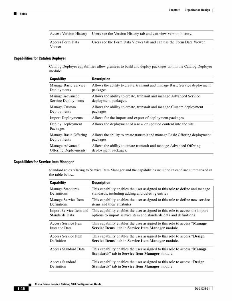
Chapter 1 Organization Design Roles
Capabilities for Catalog Deployer
Catalog Deployer capabilities allow grantees to build and deploy packages within the Catalog Deployer module.
Capabilities for Service Item Manager
Standard roles relating to Service Item Manager and the capabilities included in each are summarized in the table below.
Access Version History Users see the Version History tab and can view version history.
Access Form Data Viewer
Users see the Form Data Viewer tab and can use the Form Data Viewer.
Capability Description
Manage Basic Service Deployments
Allows the ability to create, transmit and manage Basic Service deployment packages.
Manage Advanced Service Deployments
Allows the ability to create, transmit and manage Advanced Service deployment packages.
Manage Custom Deployments
Allows the ability to create, transmit and manage Custom deployment packages.
Import Deployments Allows for the import and export of deployment packages.
Deploy Deployment Packages
Allows the deployment of a new or updated content into the site.
Manage Basic Offering Deployments
Allows the ability to create transmit and manage Basic Offering deployment packages.
Manage Advanced Offering Deployments
Allows the ability to create transmit and manage Advanced Offering deployment packages.
Capability Description
Manage Standards Definitions
This capability enables the user assigned to this role to define and manage standards, including adding and deleting entries
Manage Service Item Definitions
This capability enables the user assigned to this role to define new service items and their attributes
Import Service Item and Standards Data
This capability enables the user assigned to this role to access the import options to import service item and standards data and definitions
Access Service Item Instance Data
This capability enables the user assigned to this role to access “Manage Service Items” tab in Service Item Manager module.
Access Service Item Definition
This capability enables the user assigned to this role to access “Design Service Items” tab in Service Item Manager module.
Access Standard Data This capability enables the user assigned to this role to access “Manage Standards” tab in Service Item Manager module.
Access Standard Definition
This capability enables the user assigned to this role to access “Design Standards” tab in Service Item Manager module.
1-46Cisco Prime Service Catalog 10.0 Configuration Guide
OL-31034-01
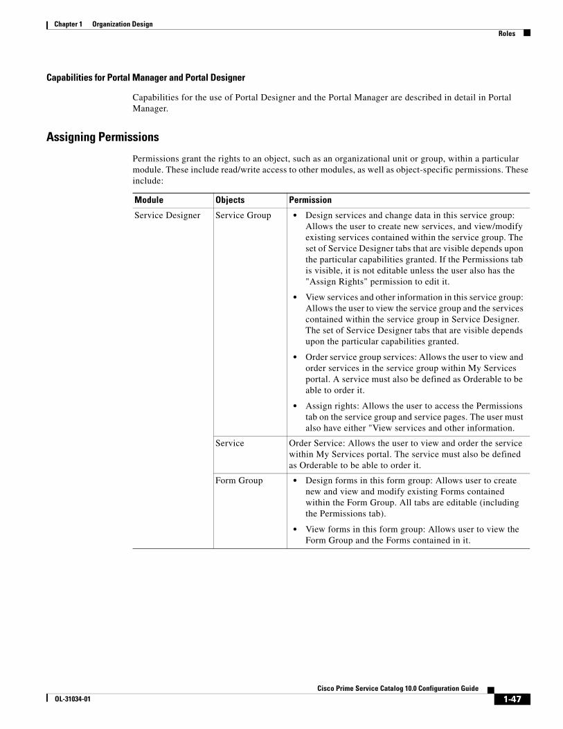
Chapter 1 Organization DesignRoles
Capabilities for Portal Manager and Portal Designer
Capabilities for the use of Portal Designer and the Portal Manager are described in detail in Portal Manager.
Assigning Permissions
Permissions grant the rights to an object, such as an organizational unit or group, within a particular module. These include read/write access to other modules, as well as object-specific permissions. These include:
Module Objects Permission
Service Designer Service Group • Design services and change data in this service group: Allows the user to create new services, and view/modify existing services contained within the service group. The set of Service Designer tabs that are visible depends upon the particular capabilities granted. If the Permissions tab is visible, it is not editable unless the user also has the "Assign Rights" permission to edit it.
• View services and other information in this service group: Allows the user to view the service group and the services contained within the service group in Service Designer. The set of Service Designer tabs that are visible depends upon the particular capabilities granted.
• Order service group services: Allows the user to view and order services in the service group within My Services portal. A service must also be defined as Orderable to be able to order it.
• Assign rights: Allows the user to access the Permissions tab on the service group and service pages. The user must also have either "View services and other information.
Service Order Service: Allows the user to view and order the service within My Services portal. The service must also be defined as Orderable to be able to order it.
Form Group • Design forms in this form group: Allows user to create new and view and modify existing Forms contained within the Form Group. All tabs are editable (including the Permissions tab).
• View forms in this form group: Allows user to view the Form Group and the Forms contained in it.
1-47Cisco Prime Service Catalog 10.0 Configuration Guide
OL-31034-01

Chapter 1 Organization Design Roles
Organization Designer
• Person
• Organizational Unit
• Queue
• Role
• Group
• Read: Allows the user to view all pages of the object record with the exception of the Administration page.
• Read/Write: Allows the user to view and edit all pages of the object record, with the exception of the Administration page.
• Change Rights: Allows the user to view and change the permission rights on the Administration page of the object record.
• Order on Behalf: Users with this permission are able to use the Order of Behalf feature of My Services for this object.
• Manage Service Team: Users with this permission are able to see the Service Team OU in the Service Team view within Service Manager.
Note This permission is available only for Organizational unit object.
• Access Queue: Users with this permission are able to see and work tasks in the queue within Service Manager, given their capabilities defined for the Service Manager module.
Note This permission is available only for Queue object.
Portal Designer • Portlet
• Portal Page
• Read: Allows the user to view the object (portlet/ page) definition in Portal Designer.
• Write: Allows the user to edit the object (portlet/ page) definition in Portal Designer.
Module Objects Permission
1-48Cisco Prime Service Catalog 10.0 Configuration Guide
OL-31034-01
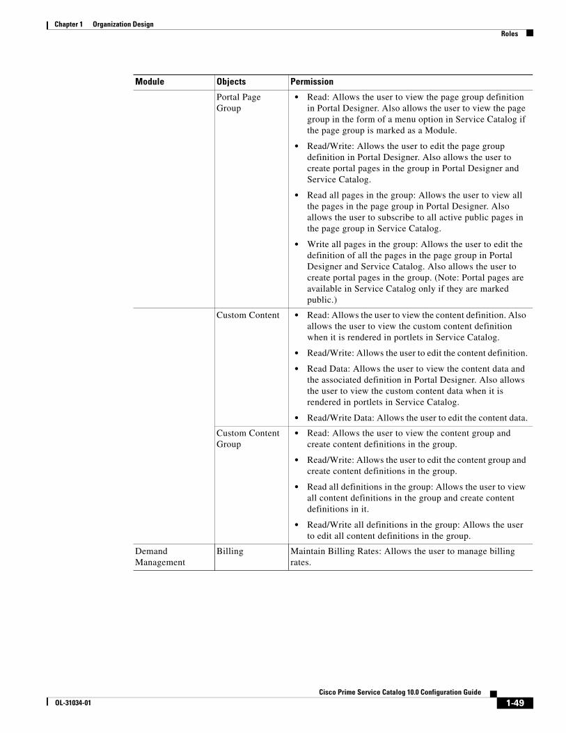
Chapter 1 Organization DesignRoles
Portal Page Group
• Read: Allows the user to view the page group definition in Portal Designer. Also allows the user to view the page group in the form of a menu option in Service Catalog if the page group is marked as a Module.
• Read/Write: Allows the user to edit the page group definition in Portal Designer. Also allows the user to create portal pages in the group in Portal Designer and Service Catalog.
• Read all pages in the group: Allows the user to view all the pages in the page group in Portal Designer. Also allows the user to subscribe to all active public pages in the page group in Service Catalog.
• Write all pages in the group: Allows the user to edit the definition of all the pages in the page group in Portal Designer and Service Catalog. Also allows the user to create portal pages in the group. (Note: Portal pages are available in Service Catalog only if they are marked public.)
Custom Content • Read: Allows the user to view the content definition. Also allows the user to view the custom content definition when it is rendered in portlets in Service Catalog.
• Read/Write: Allows the user to edit the content definition.
• Read Data: Allows the user to view the content data and the associated definition in Portal Designer. Also allows the user to view the custom content data when it is rendered in portlets in Service Catalog.
• Read/Write Data: Allows the user to edit the content data.
Custom Content Group
• Read: Allows the user to view the content group and create content definitions in the group.
• Read/Write: Allows the user to edit the content group and create content definitions in the group.
• Read all definitions in the group: Allows the user to view all content definitions in the group and create content definitions in it.
• Read/Write all definitions in the group: Allows the user to edit all content definitions in the group.
Demand Management
Billing Maintain Billing Rates: Allows the user to manage billing rates.
Module Objects Permission
1-49Cisco Prime Service Catalog 10.0 Configuration Guide
OL-31034-01

Chapter 1 Organization Design Roles
Service Item Manager
• Service Item Definition
• Service Item Group
• Standard Definition
• Standard Group
• Read: Allows the user to view object.
• Read/Write: Allows the user to edit object such as performing CRUD operations
Service Item Instance Data
• Read all Instance Data: Allows the user to view all service item instances.
• Read/Write all Instance Data: Allows the user to view and edit all service item instances
• Read all Instance Data in my BU: Allows the user to view all service item instances that is assigned to his business unit (BU)
• Read/Write all Instance Data in my BU: Allows the user to view and edit all service item instances that is assigned to his business unit (BU)
• Read all Instance Data in my BU and their sub-units: Allows the user to view all service item instances that is assigned to his business unit (BU) and its sub units
• Read/Write all Instance Data in my BU and their sub-units: Allows the user to view and edit all service item instances that is assigned to his business unit (BU) and its sub units
• Read all Instance Data in my Tenant Account: Allows the user to view all service item instances that is assigned to his tenant account
• Read/Write all Instance Data in my Tenant Account: Allows the user to view and edit all service item instances that is assigned to his tenant account
• Read all Instance Data in my Project Account: Allows the user to view all service item instances that is assigned to his project account
• Read/Write all Instance Data in my Project Account: Allows the user to view and edit all service item instances that is assigned to his project account
• Create New Instance Data: Allows the user to create new service item instance data.
Note Users are provided read access to the service they are subscribed to by default.
Module Objects Permission
1-50Cisco Prime Service Catalog 10.0 Configuration Guide
OL-31034-01

Chapter 1 Organization DesignRoles
To add a new object-level permission to a custom role, use the table above to choose the following:
Modifying an Existing Role
For system-defined roles, you can only modify the members assigned to the role, as well as read/write access to the role. Custom roles are fully modifiable, including capabilities and permissions, for those users with the correct administrative rights to do so.
Standard Table Data
• Read all Instance Data: User can view all the standard instance data.
• Read/Write all Instance Data: User can view and make changes to all standard instance data.
• Create new standard instance data: User can create new standard instance data.
Module Objects Permission
Object Type Choose an object (entity) type from the list box.
Permission for this type Based on the object type selected, choose the permission.
Assign permission to Choose one of the following:
All objects of this type – For example, if you choose organizational unit, then all organizational units are assigned this permission.
Selected Objects – Search for and choose the objects to which you wish to assign this permission.
The following additional permissions are applicable for person - object type and for read and read/write permission types only:
– All people in the Organizational Unit and its sub-units of which user is a member – The person assigned to this role gets access to read or read /write information about all people from the OU he belongs to and all people belonging to its sub OUs
– All People in Organizational Units of which user is a member– The person assigned to this role gets access to read or read /write information about all people from the OU he belongs to.
– All people that belong to the person account – The person assigned to this role gets access to read or read /write information about all people from the account he belongs to.
The following additional permissions are applicable for organization unit- object type:
– All Service Teams of which user is a member
– All Service Teams
1-51Cisco Prime Service Catalog 10.0 Configuration Guide
OL-31034-01
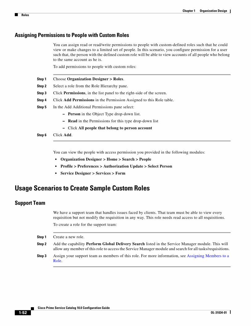
Chapter 1 Organization Design Roles
Assigning Permissions to People with Custom Roles
You can assign read or read/write permissions to people with custom-defined roles such that he could view or make changes to a limited set of people. In this scenario, you configure permission for a user such that, the person with the defined custom role will be able to view accounts of all people who belong to the same account as he is.
To add permissions to people with custom roles:
Step 1 Choose Organization Designer > Roles.
Step 2 Select a role from the Role Hierarchy pane.
Step 3 Click Permissions, in the list panel to the right-side of the screen.
Step 4 Click Add Permissions in the Permission Assigned to this Role table.
Step 5 In the Add Additional Permissions pane select:
– Person in the Object Type drop-down list.
– Read in the Permissions for this type drop-down list
– Click All people that belong to person account
Step 6 Click Add.
You can view the people with access permission you provided in the following modules:
• Organization Designer > Home > Search > People
• Profile > Preferences > Authorization Update > Select Person
• Service Designer > Services > Form
Usage Scenarios to Create Sample Custom Roles
Support Team
We have a support team that handles issues faced by clients. That team must be able to view every requisition but not modify the requisition in any way. This role needs read access to all requisitions.
To create a role for the support team:
Step 1 Create a new role.
Step 2 Add the capability Perform Global Delivery Search listed in the Service Manager module. This will allow any member of this role to access the Service Manager module and search for all tasks/requisitions.
Step 3 Assign your support team as members of this role. For more information, see Assigning Members to a Role.
1-52Cisco Prime Service Catalog 10.0 Configuration Guide
OL-31034-01

Chapter 1 Organization DesignRoles
Organization-Specific Service Team Administrator
The “Service Team Administrator” preconfigured role, described in the section above on Object-Level permissions, allows members of the role to manage any service team and to modify information on any organizational units and queues.
This role is an excellent candidate to be copied to a custom role which provides the same capabilities but limits its members to working on specific organizational units, and queues, rather than “All Objects” of each type. Responsibility for maintaining the service teams in an organization could be divided between multiple Service Team Administrator roles, each of whom has control over a different set of organizations and their queues. If the organizations were structured hierarchically, only a parent organization would need to be specified as the object of a particular permission, all child objects would also be subject to the same permission.
Support Team for an External Application
Assume that many, but not all, requisitions have an integration to an external system such as Remedy. Analysts who work on the Remedy application may need to review any Request Center requisition that includes an integration to Remedy, and may need, for example, to add attachments or comments to such requisitions.
Step 1 Create an OU of type = Service Team, named, for example, Remedy Team.
Step 2 Make all the people who need access to these requisitions members of this OU.
Step 3 Create a queue homed to the Remedy Team OU; name it Remedy Team. The Remedy Team OU now automatically gets the Access Queue permission to the queue of the corresponding name.
Step 4 For any service for which the Remedy integration is part of the delivery plan, add a task.
a. Assign the performer to be the Remedy Team queue.
b. Make the task conditional upon 1=0.
Here is why this works: Request Center grants access to a requisition based upon whether the user has “an affiliation” with the requisition. That is, if he is the customer, or the initiator, or if he plays a role in the delivery of the requisition. If a person is a performer (or has access to a queue that is a performer) of a task in the requisition, that person therefore has access to the requisition.
An alternative approach with equivalent results is to substitute the following step for Step 4 above:
• For any service for which this issue will arise, assign the plan-monitoring task to the Remedy Team queue.
Distributed Service Design
In an implementation of Request Center that spans multiple divisions within an organization, it is sometimes desirable to distribute the responsibilities for service design to multiple groups of developers. Ideally, these developers should be able to leverage each others’ work, reusing a service or service component created and tested by another group. However developers must ensure that they do not accidentally or on purpose change a design component maintained by another group.
1-53Cisco Prime Service Catalog 10.0 Configuration Guide
OL-31034-01

Chapter 1 Organization Design Roles
Such an environment can be established via the use of Permissions associated with Service Designer components. You could set up a custom role for each development group. (Members may be assigned either directly or indirectly, via membership in a service team or group.) In Service Designer that role is able to:
• Design services … in this service group (service groups containing services maintained by the team)
• Order services in this service group
• View services in possibly related services groups, or groups that might have interesting techniques for them to see
• Design forms in their own form groups
• View forms in the reserved group
• View forms in any other (common?) groups that they might need to include in their services
Rather than giving the custom role a preexisting Service Designer role, it would be preferable to grant appropriate Service Designer capabilities to the role. This option may be more work to set up, but gives you more flexibility. One thing to be careful about is in granting the group the right to import services. You could import a service and overwrite components (dictionaries or forms) that you do not normally have the ability to modify. The Import Service option does not check object-level permissions, it just overwrites (or creates) everything.
Support for Web Services
In addition to users being able to submit requisitions via My Services, Service Catalog provides the ability for external systems to submit requisitions via a web service request, using the Requisition API (RAPI). Such requests, bypassing My Services or the Service Catalog module, would never have a service form appear in the ordering moment. Consequently, their design would need to differ from that of a corresponding service that is ordered interactively. For example, no rules or Java Script functions could provide default values; and multi option fields, such as check boxes or drop-down lists, could not be used.
As a result of those limitations, designers sometimes choose to create a set of parallel services that can only be ordered via RAPI. Such services should never appear in the Service Catalog of nonadministrative users. Instead, ordering permissions should be granted only to administrative users. The RAPI service is always ordered by such a user who has been assigned the critical capability to “Order my services for others”, with the “other” specified as the customer for the request.
1-54Cisco Prime Service Catalog 10.0 Configuration Guide
OL-31034-01

CiOL-31034-01
C H A P T E R 2
User Profiles• Overview, page 2-1
• Information, page 2-1
• Preferred Language, page 2-2
• Calendar, page 2-2
• Preferences, page 2-2
OverviewThe “Profile” link on the top banner allows all users to access and change their profile.
A user Profile contains personnel Information, Preferences, and the work Calendar. You can change your user Profile at any time. The site administrator can also modify any Profile information using the People component of Organization Designer.
InformationIn a system where directory integration is configured to import person information, users should not change their personnel program using the Information page. Any such changes would be lost the next time the user profile was refreshed. Instead, contact your site administrator for assistance in updating your Profile information.
You must provide information for every field marked as required (*). In particular:
• You will need the User Name and Password to log on.
• The Work Email Address is used to send automated email notifications about your service requests.
• The Home Organizational Unit is usually the same as your department's name. This information is used by the system when services you request must be reviewed or approved by your supervisor or manager.
• The time zone is used to display scheduled start and due dates. For service performers, it is also used to determine the performer's work hours and compute the work time spent on a particular task.
2-1sco Prime Service Catalog 10.0 Configuration Guide

Chapter 2 User Profiles Preferred Language
Preferred LanguageThe My Services or Service Catalog module is available in multiple languages. By default, only US English is available in the Preferred Language drop-down list. Other languages can be made available by adding them to the Language List in the Administration module. See the “Language” section on page 3-10.
For My Services, the supported languages are as follows:
For all other modules, the only language supported is US English.
CalendarMy Services > Home> Calendar settings establish the availability of service team members to perform work.
You can:
• Set your work hours and work days.
• Set the holidays on which you are not available.
When entering Calendar information, the following applies:
• Under Working Hours, change your standard working hours and days by entering new times in military time format in the From and To fields. For example, you would enter 23:00 for 11:00 p.m. To indicate a 24-hour day, enter 12:00 as the starting time and 23:59 at the ending time.
• Enter 0:00 in the From and To fields for days that you do not work.
• Under Add New Calendar Entry, you can change a Working Day to a Holiday, and vice versa.
PreferencesPreferences govern the behavior and appearance of Service Catalog.
My Services > Profile> Preferences can control:
• Date Formats.
• Login Module – Users can choose any module which they can access to appear automatically as soon as they log in.
• Default Service Manager View – Service performers can set the system to automatically go to the Service Manager view they use most frequently.
• Default Service Manager Status (for task search) – Service performers can set the task status search condition they use most frequently.
• US English • Chinese (Simplified)
• German • Chinese (Traditional)
• French • Brazilian-Portuguese
• Spanish • Japanese
• Dutch • Korean
2-2Cisco Prime Service Catalog 10.0 Configuration Guide
OL-31034-01

Chapter 2 User ProfilesPreferences
• Time Format – 12- and 24-hour clocks are available.
• View Portlets – Allows you to suppress the appearance of the Authorizations and Service Items portlets on the My Services home page. The Authorizations and Service Items lists are still available via the corresponding tabs if the user has been granted access to these capabilities.
• Use Service Catalog – Select the checkbox if you want to use the Service Catalog module.
• Authorization Delegate information – This person can perform authorizations for you during the time period you specify using the Delegation Start Date and Delegation End Date fields.
2-3Cisco Prime Service Catalog 10.0 Configuration Guide
OL-31034-01

Chapter 2 User Profiles Preferences
2-4Cisco Prime Service Catalog 10.0 Configuration Guide
OL-31034-01

CiOL-31034-01
C H A P T E R 3
Site Administration• Overview, page 3-1
• Directory Integration, page 3-2
• Site-Wide Authorizations, page 3-2
• Email Templates, page 3-8
• Lists, page 3-9
• Site Settings, page 3-10
• Support Utilities, page 3-26
OverviewThe Administration module allows you to set up a variety of behaviors to accommodate the rules and business practices of your company.
Using the Administration module, you can:
• Link to and utilize data from your enterprise directory and other sources of user data.
• Define approval and review policies and workflow.
• Define email notification templates used in your approval and delivery processes.
• Modify standard lists of values, and publish available languages.
• Customize site-wide settings, including establishing custom style sheets to be used by specific organizational units or groups of those units.
• Access support utilities for log files, purging, version information, and viewing form data.
Administration HomeThe Administration Home page allows you to navigate throughout the module, using either the tabs on the navigation bar or the links within the Content Pane.
3-1sco Prime Service Catalog 10.0 Configuration Guide
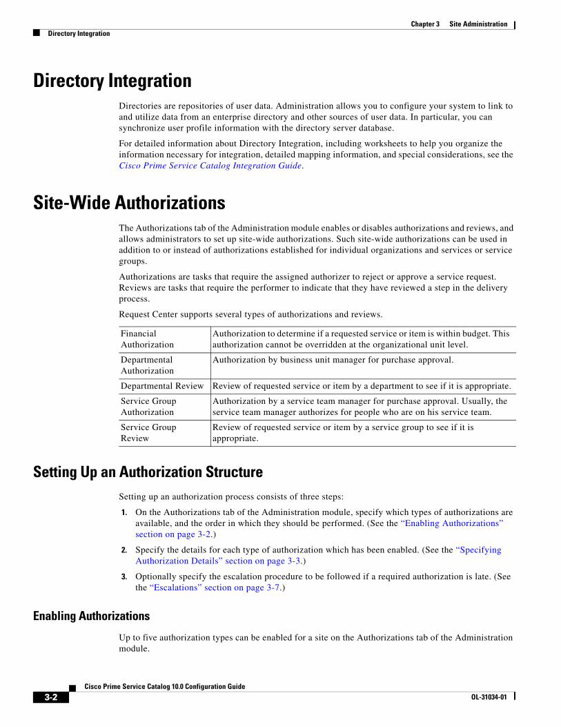
Chapter 3 Site Administration Directory Integration
Directory IntegrationDirectories are repositories of user data. Administration allows you to configure your system to link to and utilize data from an enterprise directory and other sources of user data. In particular, you can synchronize user profile information with the directory server database.
For detailed information about Directory Integration, including worksheets to help you organize the information necessary for integration, detailed mapping information, and special considerations, see the Cisco Prime Service Catalog Integration Guide.
Site-Wide AuthorizationsThe Authorizations tab of the Administration module enables or disables authorizations and reviews, and allows administrators to set up site-wide authorizations. Such site-wide authorizations can be used in addition to or instead of authorizations established for individual organizations and services or service groups.
Authorizations are tasks that require the assigned authorizer to reject or approve a service request. Reviews are tasks that require the performer to indicate that they have reviewed a step in the delivery process.
Request Center supports several types of authorizations and reviews.
Setting Up an Authorization StructureSetting up an authorization process consists of three steps:
1. On the Authorizations tab of the Administration module, specify which types of authorizations are available, and the order in which they should be performed. (See the “Enabling Authorizations” section on page 3-2.)
2. Specify the details for each type of authorization which has been enabled. (See the “Specifying Authorization Details” section on page 3-3.)
3. Optionally specify the escalation procedure to be followed if a required authorization is late. (See the “Escalations” section on page 3-7.)
Enabling Authorizations
Up to five authorization types can be enabled for a site on the Authorizations tab of the Administration module.
Financial Authorization
Authorization to determine if a requested service or item is within budget. This authorization cannot be overridden at the organizational unit level.
Departmental Authorization
Authorization by business unit manager for purchase approval.
Departmental Review Review of requested service or item by a department to see if it is appropriate.
Service Group Authorization
Authorization by a service team manager for purchase approval. Usually, the service team manager authorizes for people who are on his service team.
Service Group Review
Review of requested service or item by a service group to see if it is appropriate.
3-2Cisco Prime Service Catalog 10.0 Configuration Guide
OL-31034-01

Chapter 3 Site AdministrationSite-Wide Authorizations
To change the status of an authorization type, under the Action column for the authorization type you want to change, click Edit and choose Enable or Disable from the Status drop-down menu. To change the order of execution, in the Action column click the Up or Down Arrow buttons ( ) until it is in the correct sequence.
Specifying Authorization Details
If an authorization/review type is enabled, you can then specify details for that authorization/review type. Authorization details can be defined:
• At the site-level (Administration > Authorizations)
• For each organization for Departmental Authorizations/Reviews (Organization Designer > Org Units > Authorizations)
• For a service group or service for Service Group Authorizations/Reviews (Service Designer > Authorizations)
For Departmental Authorizations/Reviews you have the option to:
• Use site authorization structure only
• Use departmental level authorization only (Will not use site level)
• Use both site and departmental level authorizations structures
For Service Group Authorizations/Reviews you have the option to:
• Use service group authorization structure only
• Use service level authorization only (will not use service group-level)
• Use both service group level and service level authorizations structures
If you choose the “Use site authorization structure only” or “Use service group authorization structure only” option, then no further steps are required. Otherwise, you may choose the Authorization Type you wish to configure:
• An Authorization (Departmental or Service Group) – Authorizations are processed sequentially within the approval moment. Each authorizer must either Reject or Approve the request. If the request is approved, it passes to the next authorization or next step in the delivery process. If the request is cancelled, no further tasks are performed.
• A Review (Departmental or Service Group) – The review process runs concurrently within the approval moment. Reviewers simply click OK to signify that they have reviewed the request—they do not have the capability of stopping the delivery.
Note All authorization and review tasks must be completed before the delivery process begins.
On the Authorizations tab of the Administration module, in the Actions column next to the authorization or review you want to edit, click Edit. Based on the authorization type you choose, either the Authorizations – Sequential Process (shown below) or Reviews – Concurrent Process subtab appears.
3-3Cisco Prime Service Catalog 10.0 Configuration Guide
OL-31034-01

Chapter 3 Site Administration Site-Wide Authorizations
Note The Up and Down Arrow buttons ( ) to the right of each role allow you to move the role up or down in the approval process.
This following table defines the fields on the Details screen (which appears after you click Add on one of these subtabs, or choose a previously defined authorization/review role by checking the check box to the left of the Name field in one of these subtabs). Click Update to save changes.
Name* Name for the new responsibility being performed by the authorizer or reviewer.
Duration* Amount of time, in hours, allotted for the authorization or review task.
Subject* Name of the authorization or review task that this responsibility performs. This value appears in the Task List that authorizers and reviewers see in Service Manager.
You can use namespace variables in the task titles. A string enclosed in hash marks (#) denotes a namespace variable. The variable is replaced by the service name being ordered. See the Cisco Prime Service Catalog Designer Guide for details.
Effort* Amount of time that it takes to perform the review or authorization. This is typically less than the Duration.
Workflow Type Choose internal if the authorizer is someone within the system, or choose an available external workflow to perform the authorization via a Service Link task.
Assign Choose one of the following from the drop-down menu:
• From a position – authorization or review is fulfilled by the person currently filling the designated functional position
• A person/queue – authorization or review is fulfilled by the designated person or queue
• From an expression – authorization or review is fulfilled based on the expression entered in the “Assign to” field
Assign to Click to choose the value that corresponds to your selection for the Assign field. If you choose From an expression, enter the expression. Expression syntax is documented in the Cisco Prime Service Catalog Designer Guide.
3-4Cisco Prime Service Catalog 10.0 Configuration Guide
OL-31034-01

Chapter 3 Site AdministrationSite-Wide Authorizations
Fields marked with an asterisk (*) are required.
Escalation Tiers Click one of the following:
• Use all – All escalations set up for this process are used.
• Use only – If you do not wish to use all the escalation tiers set up for this authorization or review process, enter the number of tiers you do wish to use.
Condition Expressions containing conditions which need to be met for approval. Using True or False, it indicates if the task will occur or not. If you do not enter an expression, the default value is True and the authorization will always be executed.
Click Validate to verify that the expression you are using will work. Validation only executes a syntactical check; the validation function does not check to see if the data you are referencing actually exists in the request.
Evaluate condition when Choose either:
• Authorization phase starts (if condition evaluates to “false”, times will be computed as zero). The condition entered in the Condition field becomes active as soon as the authorization phase begins.
• Task becomes active (times will not be affected, scheduling is done by using these efforts) – The condition entered in the Condition field becomes active when the authorization phase completes and the task after the authorization begins.
Re-evaluate expression as authorizations/reviews proceed
Check the check box if you wish the performer name or task name to be re-evaluated after every authorization task, and updated as necessary. Due dates for the authorization do not change. This setting should be used if the performer is assigned via an expression, and a previous authorization step may have allowed the authorizer to change the value of a field used in that expression.
Notify when authorization/review starts
Email templates are automatically sent at every phase appropriately. A list of email templates available in the system is displayed in the drop-down list.Notify when
authorization/review completes
Notify when requisition/activity is cancelled
Notify when requisition/activity is rejected
Notify when task is rescheduled
Notify when task is reassigned
Notify when external tasks fail
3-5Cisco Prime Service Catalog 10.0 Configuration Guide
OL-31034-01
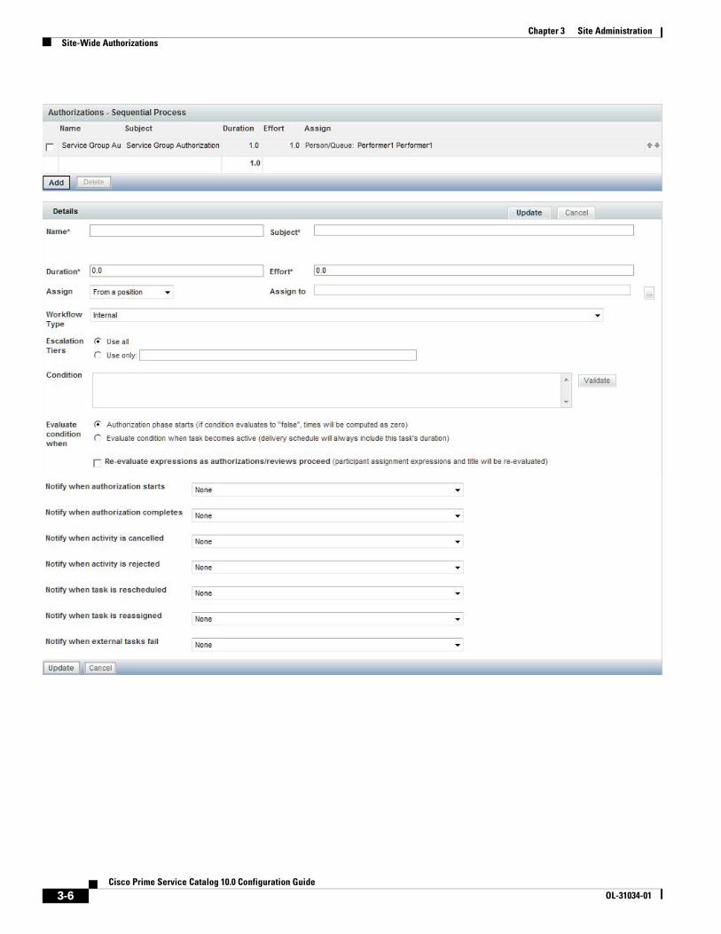
Chapter 3 Site Administration Site-Wide Authorizations
3-6Cisco Prime Service Catalog 10.0 Configuration Guide
OL-31034-01

Chapter 3 Site AdministrationSite-Wide Authorizations
Escalations
Escalations are a process whereby a certain activity that has not been performed within the designated duration is flagged and sent to the appropriate performer, supervisor, or customer for resolution. Recipients receive notification of the delayed task in the form of an email.
When setting up an escalation process, keep in mind the following:
• Each row in the escalation list represents a tier. You can have as many tiers as you want—simply click Add to add another tier. (You may delete a tier by checking the corresponding check box and clicking Delete.)
• The first tier represents the first group to be notified when a task exceeds its standard duration. The time—After (hours)—represents the number of hours after the due date before the notification is sent.
• After the first notification, the time specified for subsequent tiers represent the time elapsed since the previous escalation. For example, if the second tier has 8 hours as the time, then 8 hours after the first notification is sent without a resolution triggers the second group notification.
• Up to three recipients can receive an escalation notification for each tier. For each Recipient box, you enter a list of valid email addresses, separated by commas. Namespace references of the type #variable# are also permitted. For example, #Perfomer.Manager.Email# would direct the notification to the manager of the task performer.
– For each recipient, use the corresponding drop-down box to choose the emails used to notify the recipients. The notifications are derived using templates created within the Administration module.
Escalations are actually sent out by the Escalation Manager, which is part of the Business Engine, the workflow manager. By default, the Escalation Manager checks for late tasks with associated escalations once an hour, on the hour, during normal work hours. So, it is not quite correct to state, as above, that an email notification is sent after the authorization has been late for the designated number of hours. The notification will actually be sent the next time the Escalation Manager checks for late tasks after the escalation period has expired. For example, if an authorization was due at 12:30 PM, and an escalation notice is set to be sent 1 hour later (at 1:30 PM), the notification will actually be sent at 2 PM, the next time the Escalation Manager runs.
The administrator can change Escalation Manager settings. The procedure for doing so is documented in Chapter 5, “System Administration”.
3-7Cisco Prime Service Catalog 10.0 Configuration Guide
OL-31034-01

Chapter 3 Site Administration Email Templates
Email TemplatesService Catalog includes a set of preconfigured email templates. You can set up a service's delivery plan to automatically send these in response to events that occur. The Administration module allows you to create new and modify provided templates used in email notifications. These email are used to inform recipients of steps within the approval and delivery process.
Templates used by Request Center are found under the General link. Templates used by Demand Center are found under Agreement Email Templates. You can set up Administration so that the system automatically sends these in response to events that occur. For example, when a service requires authorization from a manager, the system can send the manager an email notifying that a service request requires approval. You can change the included templates or add templates suitable for your organization.
Viewing Email TemplatesYou can view email template information using one of the following methods:
• On the Home page, click Manage Email Templates. On the Email Templates navigation pane, click the template name you wish to open to view.
• On the navigation bar, click Notifications. On the Email Templates navigation pane, click the template name you wish to open to view.
Clicking the template name displays the template styling options and content. A sample Request Center template is shown below.
3-8Cisco Prime Service Catalog 10.0 Configuration Guide
OL-31034-01
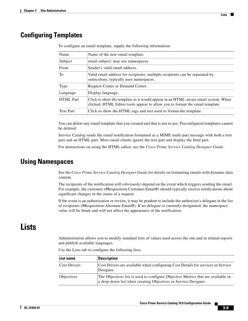
Chapter 3 Site AdministrationLists
Configuring TemplatesTo configure an email template, supply the following information:
You can delete any email template that you created and that is not in use. Preconfigured templates cannot be deleted.
Service Catalog sends the email notification formatted as a MIME multi part message with both a text part and an HTML part. Most email clients ignore the text part and display the html part.
For instructions on using the HTML editor, see the Cisco Prime Service Catalog Designer Guide.
Using NamespacesSee the Cisco Prime Service Catalog Designer Guide for details on formatting emails with dynamic data content.
The recipients of the notification will (obviously) depend on the event which triggers sending the email. For example, the customer (#Requisition.Customer.Email#) should typically receive notifications about significant changes in the status of a request.
If the event is an authorization or review, it may be prudent to include the authorizer's delegate in the list of recipients (#Requisition.Alternate.Email#). If no delegate is currently designated, the namespace value will be blank and will not affect the appearance of the notification.
ListsAdministration allows you to modify standard lists of values used across the site and in related reports and publish available languages.
Use the Lists tab to configure the following lists:
Name Name of the new email template.
Subject email subject; may use namespaces.
From Sender's valid email address.
To Valid email address for recipients; multiple recipients can be separated by semicolons; typically uses namespaces.
Type Request Center or Demand Center.
Language Display language.
HTML Part Click to show the template as it would appear in an HTML-aware email system. When clicked, HTML Editor tools appear to allow you to format the email template.
Text Part Click to show the HTML tags and text used to format the template.
List name Description
Cost Drivers Cost Drivers are available when configuring Cost Details for services in Service Designer.
Objectives The Objectives list is used to configure Objective Metrics that are available in a drop-down list when creating Objectives in Service Designer.
3-9Cisco Prime Service Catalog 10.0 Configuration Guide
OL-31034-01

Chapter 3 Site Administration Site Settings
LanguageThe My Services module is available in multiple languages. The Language list is used to manage the list of languages which are available for users to choose in the Preferred Language drop-down list in their Person Profile (see the “Preferred Language” section on page 2-2). By default, only US English is available in the Preferred Language drop-down list. Other languages can be made available by adding them to the Language List. Click Add, choose the language from the drop-down list, and then click Update. No additional configuration steps are required.
For My Services, the supported languages are as follows:
• US English
• German
• French
• Spanish
• Dutch
• Chinese (Simplified)
• Chinese (Traditional)
• Brazilian-Portuguese
• Japanese
• Korean
For all other modules, the only language supported is US English.
Site SettingsAdministration allows you to customize a variety of behaviors to suit the policies and working practices of your organization. You can set these options by clicking the Settings tab. The Settings tab displays the following options:
Unit of Measure Units of Measure are used in conjunction with Metrics to configure Objectives in Service Designer.
Language The Language list is used to manage the list of languages that are available for users to choose in the Preferred Language drop-down list in the user profile and in the person information. For more information, see the “Language” section on page 3-10.
Page Description
Customizations Configure site-wide settings for various modules.
Person Popup Set the type of information that displays when conducting a person search.
Entity Homes Specify the definitional data that can be modified on the sites of an implementation.
Debugging Specify whether to display debugging information within the user interface.
Custom Styles Define and specify the organizations to which they apply.
Data Source Registry View the data sources registered with the application.
3-10Cisco Prime Service Catalog 10.0 Configuration Guide
OL-31034-01

Chapter 3 Site AdministrationSite Settings
CustomizationsCustomizations allow you to set options according to the business practices of your organization. The Customizations settings are divided into groups depending on the module or modules affected and the capabilities provided by each setting.
The following values are available for customization:
Asynchronous Submission/Last Approval
In order for Service Catalog to process a service request, it must create a series of records in the transactional database corresponding to the authorization and delivery tasks that comprise the service workflow. For complex delivery plans, creating these tasks and computing the scheduled start and end dates of all tasks, based on the participants assigned, their work calendars and the specified task duration, may consume a substantial amount of time, during which the user (whether the requestor or the last approval) must sit and wait for acknowledgement that their attempt to submit the service request has been processed.
To eliminate this wait time, Service Catalog provides the option to implement asynchronous task instantiation. That is, when the request is submitted (or last approval completed, if the request has any authorizations or reviews), Service Catalog will only update (or create) the service request itself before allowing the user to continue. The remaining processing—of creating the tasks and computing due dates—are performed asynchronously, in the background.
This results in one major change in the user interface (elimination of the wait time!) and some minor changes. After requisition submission, the status becomes “Ordered” until it is processed by the Business Engine. Afterwards, the status becomes “Ongoing”.
In the rare case when Service Catalog encounters an error in creating all the tasks, a notification email can be sent to concerned parties. Two email templates can be designated: one for use if a request fails to be submitted, and the second if the last approval fails to be processed correctly. Templates are designed using the Notifications option in the Administration module and associated with each event via the
KpiSourceOfData Controls where the KPI charts retrieve data. Should be set to “Datamart”.
SessionTimeOut Sets the session time out; default is 20 minutes; may be any interval up to two hours (240 minutes).
API SessionTimeout Sets the session Timeout for all APIs. If any nsAPIs are directly called with credentials (without calling nsAPI login) then the Session should be automatically terminate after the response is sent.
Attachment Maximum Size Sets the maximum size of the file that can be uploaded as an attachment to a service request. 0 indicates no maximum size.
Attachment File Type Restrictions
Defines the file types that are allowed/prevented from being attached. Specify these as a list of file extensions separated by comma; for example: .exe, .bmp, or .zip.
Order Confirmation Email Template
Email notification to be sent when a customer submits a requisition.
Image Maximum Size Sets the maximum size of the file that can be uploaded as an attachment 0 indicates no maximum size.
Image Types Allowed Defines the image types that are allowed. Specify these as a list of file extensions separated by comma. For example: .jpg,.img,.bmp. By default, the following images types allowed: .jpg,.png,.gif,.jpeg,.tiff,.exif,.svg
3-11Cisco Prime Service Catalog 10.0 Configuration Guide
OL-31034-01
Chapter 3 Site Administration Site Settings
Administration > Settings > Customizations settings. Failed requests can be viewed and sent for retry on the Administration Debugging page. See the “Monitor for Asynchronous Submission Messages” section on page 3-23 for more details.
Asynchronous task instantiation is off by default. You must activate this behavior by turning on the “Submit, Approve and Review Asynchronously” setting in the Common section of Administration > Settings > Customizations.
Browser Cache Setting
This setting enables the use of browser caching for application files that are mostly static in a production environment. Use of this feature could significantly improve page load times for users in remote locations by leveraging cached objects and prompting refresh only when version changes are detected.
When browser caching is enabled, a cookie is placed in the browser client to track the last accessed version, and allows the application to make use of the cached version of the following types of objects:
• Images (*.gif, *.jpg, *.png, *.bmp)
• Stylesheets (*.css)
• ISF libraries (*.js and *.cfm deployed under RequestCenter.war; this does not include JavaScripts generated on the fly by streamJS.jsStream for conditional rules, and user-defined JavaScripts)
• HTML (*.html, *.htm) pages
When an application change event happens (for example, deploying a service with modified images through Catalog Deployer), administrators can prompt users to delete their browser cache by incrementing the version number.
Users who have browser cookies registering a different version from the one in the Administration Settings will be prompted to delete the browser cache. Once the browser cache has been deleted, they can click “Login Again” (or “Continue”, when Single Sign-On is enabled) to access the application.
JMS Credentials
The JMS username and password values are first captured when the application is installed. Subsequent changes to the credentials on the application server side (as necessitated by corporate password policies or other requirements), the updated values need to be entered here to allow the Prime Service Catalog application to continue to have access to the JMS queues.
Order Failure Email Template
Email to be sent if the order submission process fails unexpectedly. This entry takes effect only if the “Submit, Approve and Review Tasks Asynchronously” setting is on.
Approval Failure Email Template
Email to be sent if an approval or review task performed by the user fails unexpectedly. This entry takes effect only if “Submit, Approve and Review Tasks Asynchronously” setting is on.
3-12Cisco Prime Service Catalog 10.0 Configuration Guide
OL-31034-01

Chapter 3 Site AdministrationSite Settings
Common Settings
The Common Settings affect the behavior of multiple modules.
Enable Custom Header Footer Enable custom header and footer.
Default is off.
Enable Custom Style Sheets Use a custom style sheet for formatting the site, allowing for the changing of logos, color schemes, fonts, and other HTML attributes.
Default is off.
Directory Integration Enable the Directories feature that searches for and imports users into the site from an external datasource.
Default is off.
Restrict Site Administrator URL
Allow only those users with the Site Administrator role to log in using the administrative URL to bypass Single Sign-On.
Default is off.
Use Image Path Replacement Use a dynamic variable in place of the server portion of presentation image URLs.
Default is off.
Use Strong Encryption Use strong encryption for form data and document attachments. Use is not recommended.
Default is off.
Show KPI Portlet Turn the Key Performance Indicators (KPI) portlet feature on or off. If the feature is on, users who can run My Services Executive will be able to see KPIs on their My Services home page. KPIs are always viewable in the Reporting dashboard for users with permissions to access the Reporting module.
Default is off.
Submit, Approve, and Review Asynchronously
Enable or disable background processing of requisition submit, and of completion of approvals and reviews.
Default is off.
Deploy Entries (data) in Standards Tables
Enable or disable the inclusion of entries (data) from Standards tables, in addition to the definition of those tables, when creating Catalog Deployer packages. Leave this Off if you do not wish to have Standards data overwritten by a package deployment.
Default is on.
Show Login Name Show or hide the display of person login name on the view person profile popup page.
Default is off.
Accept encrypted Password When enabled, the password used for inbound HTTP requests must be in encrypted format.
Default is off.
Enable Historical Requisitions View
When enabled, Historical Requisitions can be accessed in MyServices and Service Manager.
Default is off.
3-13Cisco Prime Service Catalog 10.0 Configuration Guide
OL-31034-01
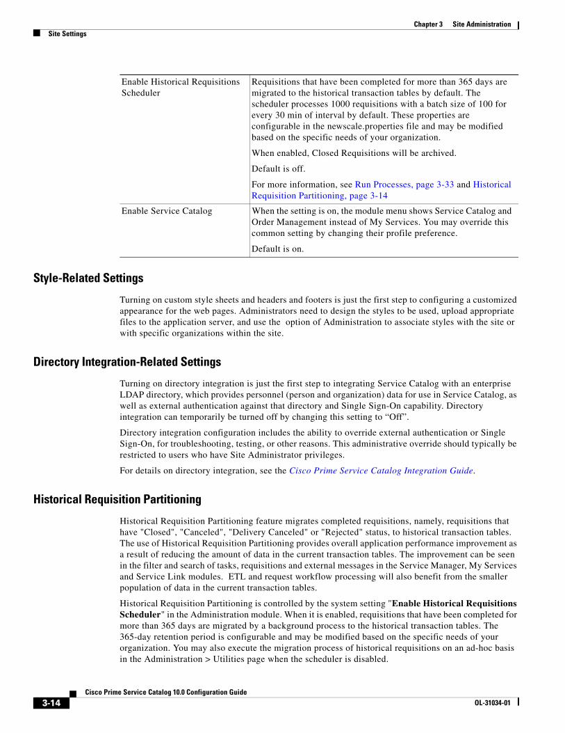
Chapter 3 Site Administration Site Settings
Style-Related Settings
Turning on custom style sheets and headers and footers is just the first step to configuring a customized appearance for the web pages. Administrators need to design the styles to be used, upload appropriate files to the application server, and use the option of Administration to associate styles with the site or with specific organizations within the site.
Directory Integration-Related Settings
Turning on directory integration is just the first step to integrating Service Catalog with an enterprise LDAP directory, which provides personnel (person and organization) data for use in Service Catalog, as well as external authentication against that directory and Single Sign-On capability. Directory integration can temporarily be turned off by changing this setting to “Off”.
Directory integration configuration includes the ability to override external authentication or Single Sign-On, for troubleshooting, testing, or other reasons. This administrative override should typically be restricted to users who have Site Administrator privileges.
For details on directory integration, see the Cisco Prime Service Catalog Integration Guide.
Historical Requisition Partitioning
Historical Requisition Partitioning feature migrates completed requisitions, namely, requisitions that have "Closed", "Canceled", "Delivery Canceled" or "Rejected" status, to historical transaction tables. The use of Historical Requisition Partitioning provides overall application performance improvement as a result of reducing the amount of data in the current transaction tables. The improvement can be seen in the filter and search of tasks, requisitions and external messages in the Service Manager, My Services and Service Link modules. ETL and request workflow processing will also benefit from the smaller population of data in the current transaction tables.
Historical Requisition Partitioning is controlled by the system setting "Enable Historical Requisitions Scheduler" in the Administration module. When it is enabled, requisitions that have been completed for more than 365 days are migrated by a background process to the historical transaction tables. The 365-day retention period is configurable and may be modified based on the specific needs of your organization. You may also execute the migration process of historical requisitions on an ad-hoc basis in the Administration > Utilities page when the scheduler is disabled.
Enable Historical Requisitions Scheduler
Requisitions that have been completed for more than 365 days are migrated to the historical transaction tables by default. The scheduler processes 1000 requisitions with a batch size of 100 for every 30 min of interval by default. These properties are configurable in the newscale.properties file and may be modified based on the specific needs of your organization.
When enabled, Closed Requisitions will be archived.
Default is off.
For more information, see Run Processes, page 3-33 and Historical Requisition Partitioning, page 3-14
Enable Service Catalog When the setting is on, the module menu shows Service Catalog and Order Management instead of My Services. You may override this common setting by changing their profile preference.
Default is on.
3-14Cisco Prime Service Catalog 10.0 Configuration Guide
OL-31034-01

Chapter 3 Site AdministrationSite Settings
As a result of the above changes, requisition views in both My Services and Service Manager are now separated into "Recent" and "Historical" views. Requisitions migrated to the historical transaction tables can be made accessible in the user interface by turning on the "Enable Historical Requisitions View" system setting. These requisitions are displayed on the "Historical" subtab on the My Services > Requisitions page, as well as the "Historical Requisitions" view in Service Manager. Tasks and external messages associated with the historical requisitions are currently not available for viewing in the user interface although the data are still stored within the Request Center database. The ability to access them online will be enabled in future releases and/or patches.
Preparing for Historical Requisition Partitioning
The first-time execution of the historical requisition migration will likely cover a large amount of data. To reduce the impact to application users, consider executing the process manually from the Administration module during one or multiple off-peak periods. To do so, navigate to Administration module and ensure that the "Enable Historical Requisitions Scheduler" setting is off. Then navigate to the "Run Processes" subtab under Utilities, enter the desired cut-off date and, optionally, the batch size and maximum number of requisitions to process. A larger batch size shortens the processing time but requires higher amount of temporary space or rollback segment in the database server. Setting the maximum number of requisitions or clicking the "Stop" button at any time allows you to limit the duration of the historical requisition migration process.
The processing rate and duration vary based on the average size of the requisitions. Before executing the migration process in your production environment, you should work with the database administrators and perform trial runs to estimate the time required for the first-time execution.
Considerations for Datamart
If you have the Reporting module, please note that historical transaction data are not extracted by the ETL process. Consider the following when configuring the historical requisition partitioning feature:
• ETL process is normally scheduled to run on a frequent basis. Hence requisition data would have been captured into Datamart prior to their migration to the historical tables. To ensure there is no data loss in the Datamart, always set the historical requisition retention period to be greater than the frequency of the ETL process. For example, if ETL is set to run every 30 days, the historical requisition retention period should be set to 31 days or more.
• The process that migrates historical transaction data is automatically put on hold when it detects that the most recent ETL process timestamp is earlier than the cutoff date. For example, if the last ETL execution was on May 1st 12pm and the migration is going to select requisitions completed before May 1st 12:30pm, the migration process will exit immediately. This ensures that data are kept in the current transaction tables for extraction into Datamart before they get migrated.
• If your organization has the need to rebuild Datamart occasionally to capture backdated data (for example, making a dictionary or service reportable after the fact), the changes will not take effect on historical transactions by re-running the ETL process. In fact, the historical data will not be recoverable in the Datamart once they have been purged. To ensure such Datamart rebuild process is still possible, configure the data retention period to a duration that has provisions for backdated changes. In addition, the Datamart should no longer be emptied in a rebuild process for the reason above. Only the portion of data that are still available in the current transaction tables can be deleted and re-inserted into the Datamart during the re-execution of ETL.
Key Settings for Historical Requisition Processing
1. newscale.properties file (located in the RequestCenter.ear/config directory)
3-15Cisco Prime Service Catalog 10.0 Configuration Guide
OL-31034-01

Chapter 3 Site Administration Site Settings
– reqArchival.poller.cron - This controls the frequency of the background process that migrates historical data. It uses the standard cron syntax and is scheduled to run every 30 minutes.
– reqArchival.process.maxRecords - This controls the maximum number of requisitions to be processed in each run. A higher number may be set if the process is intended to be run for a longer period of time during scheduled maintenance.
– reqArchival.cutOffDate.days - This controls the retention period of completed requisitions in the current transaction tables. By default, the retention period is set to 365 days.
– reqArchival.process.batchSize - This controls the number of historical requisitions included during each database commit. A larger batch size will shorten the processing time but will require higher amount of temp space or rollback segment in the database server.
2. support.properties file (located in the RequestCenter.ear/config directory)
– reqArchival.poller.enable - This controls whether the application instance can be used to run the historical requisition migration process. In a clustered Request Center environment, only one of the nodes will be used to execute the migration process at any time. One or more of the nodes may have this property set to "false" if the server is a less powerful machine or is meant for disaster recovery purpose.
Other settings in the above files should remain unchanged under normal circumstances.
Catalog Deployer-Related Settings
When Catalog Deployer deploys a service, the definitions of any standards referenced by that service (typically in the form of data retrieval rules) are automatically deployed and entries (data) for those standards are also deployed. The setting to “Deploy Entries (data) in Standards Tables” allows you to override that behavior. If set to “No”, Catalog Deployer does not deploy standards data to the target environment. It is assumed that data is loaded into the target environment via alternate methods, either through manual entry using Lifecycle Center or by importing the standards data.
For more information, see the Cisco Prime Service Catalog Designer Guide.
My Services Settings
The My Services settings control the behavior and appearance of the My Services module.
Show Plan In My Services Allow customers to see the status of tasks in the delivery plan for their requested services.
Default is off.
Allow Update Quantity Allow My Services users to update the quantity for service requests.
Default is off.
Use Categories In Search Include category names in the My Services search feature. Services contained within matching categories appear in the search results.
Default is on.
Display Empty Category Show or hide categories that do not contain services in the My Services portal.
Default is off.
3-16Cisco Prime Service Catalog 10.0 Configuration Guide
OL-31034-01
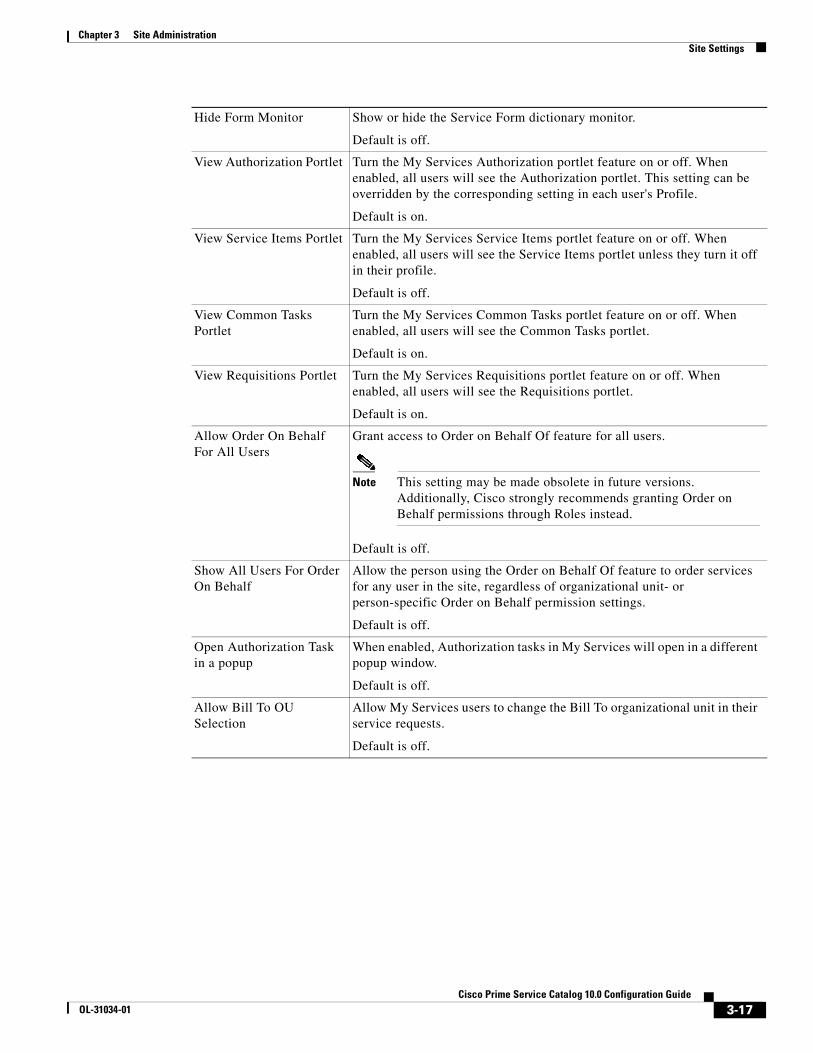
Chapter 3 Site AdministrationSite Settings
Hide Form Monitor Show or hide the Service Form dictionary monitor.
Default is off.
View Authorization Portlet Turn the My Services Authorization portlet feature on or off. When enabled, all users will see the Authorization portlet. This setting can be overridden by the corresponding setting in each user's Profile.
Default is on.
View Service Items Portlet Turn the My Services Service Items portlet feature on or off. When enabled, all users will see the Service Items portlet unless they turn it off in their profile.
Default is off.
View Common Tasks Portlet
Turn the My Services Common Tasks portlet feature on or off. When enabled, all users will see the Common Tasks portlet.
Default is on.
View Requisitions Portlet Turn the My Services Requisitions portlet feature on or off. When enabled, all users will see the Requisitions portlet.
Default is on.
Allow Order On Behalf For All Users
Grant access to Order on Behalf Of feature for all users.
Note This setting may be made obsolete in future versions. Additionally, Cisco strongly recommends granting Order on Behalf permissions through Roles instead.
Default is off.
Show All Users For Order On Behalf
Allow the person using the Order on Behalf Of feature to order services for any user in the site, regardless of organizational unit- or person-specific Order on Behalf permission settings.
Default is off.
Open Authorization Task in a popup
When enabled, Authorization tasks in My Services will open in a different popup window.
Default is off.
Allow Bill To OU Selection
Allow My Services users to change the Bill To organizational unit in their service requests.
Default is off.
3-17Cisco Prime Service Catalog 10.0 Configuration Guide
OL-31034-01

Chapter 3 Site Administration Site Settings
Form Monitor
The Form Monitor appears to the right of a service form. It shows the dictionaries in the form. A dictionary is checked when all mandatory fields in that dictionary have been provided values. The mandatory field status check is not applied to grid dictionaries.
The Form Monitor is generally useful. However, it may be confusing if a dictionary is hidden by a rule or ISF code after the service form appears; the dictionary will still be listed in the Form Monitor.
Authorizations Portlet
The Authorizations Portlet provides a quick way to view and access any authorizations assigned to the current user. If users are able to view their authorizations, this portlet appears on the left side of the My Services screen.
The Authorizations Portlet provides a quick view of the five most recent authorizations and a means of displaying all authorizations assigned to the current user. Authorizations are also accessible via the Common Tasks > Authorizations link and the Authorizations tab in the navigation bar of the My Services module.
Service Items Portlet
The Service Items Portlet provides a quick way to view and access any service items assigned to the current user. This portlet is available only for sites that have licensed Lifecycle Center.
The Service items Portlet provides a quick view of the five most recently provisioned service items and a means of displaying all service items assigned to the current user. Service Items are also accessible via the Service Items tab in the navigation bar of the My Services module.
3-18Cisco Prime Service Catalog 10.0 Configuration Guide
OL-31034-01
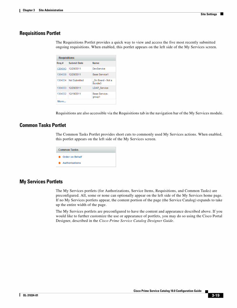
Chapter 3 Site AdministrationSite Settings
Requisitions Portlet
The Requisitions Portlet provides a quick way to view and access the five most recently submitted ongoing requisitions. When enabled, this portlet appears on the left side of the My Services screen.
Requisitions are also accessible via the Requisitions tab in the navigation bar of the My Services module.
Common Tasks Portlet
The Common Tasks Portlet provides short cuts to commonly used My Services actions. When enabled, this portlet appears on the left side of the My Services screen.
My Services Portlets
The My Services portlets (for Authorizations, Service Items, Requisitions, and Common Tasks) are preconfigured. All, some or none can optionally appear on the left side of the My Services home page. If no My Services portlets appear, the content portion of the page (the Service Catalog) expands to take up the entire width of the page.
The My Services portlets are preconfigured to have the content and appearance described above. If you would like to further customize the use or appearance of portlets, you may do so using the Cisco Portal Designer, described in the Cisco Prime Service Catalog Designer Guide.
3-19Cisco Prime Service Catalog 10.0 Configuration Guide
OL-31034-01
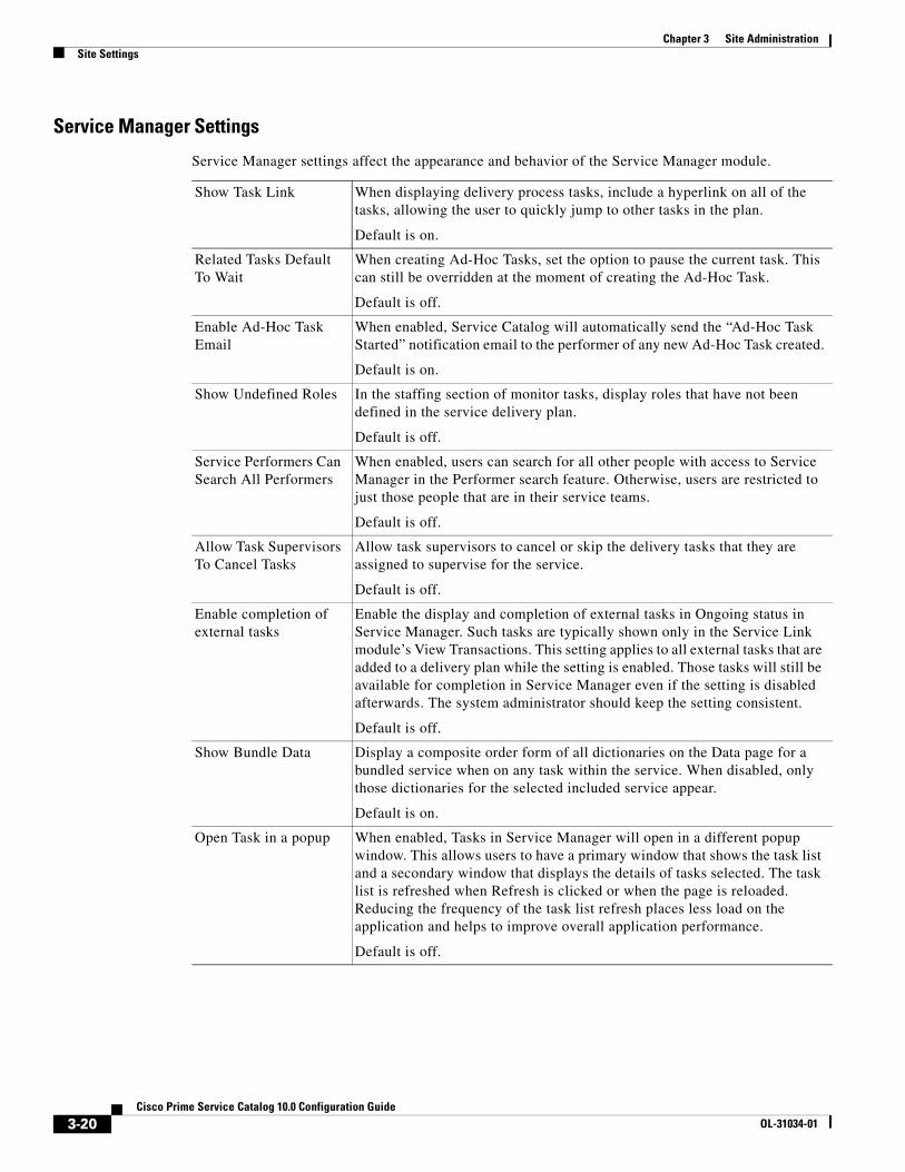
Chapter 3 Site Administration Site Settings
Service Manager Settings
Service Manager settings affect the appearance and behavior of the Service Manager module.
Show Task Link When displaying delivery process tasks, include a hyperlink on all of the tasks, allowing the user to quickly jump to other tasks in the plan.
Default is on.
Related Tasks Default To Wait
When creating Ad-Hoc Tasks, set the option to pause the current task. This can still be overridden at the moment of creating the Ad-Hoc Task.
Default is off.
Enable Ad-Hoc Task Email
When enabled, Service Catalog will automatically send the “Ad-Hoc Task Started” notification email to the performer of any new Ad-Hoc Task created.
Default is on.
Show Undefined Roles In the staffing section of monitor tasks, display roles that have not been defined in the service delivery plan.
Default is off.
Service Performers Can Search All Performers
When enabled, users can search for all other people with access to Service Manager in the Performer search feature. Otherwise, users are restricted to just those people that are in their service teams.
Default is off.
Allow Task Supervisors To Cancel Tasks
Allow task supervisors to cancel or skip the delivery tasks that they are assigned to supervise for the service.
Default is off.
Enable completion of external tasks
Enable the display and completion of external tasks in Ongoing status in Service Manager. Such tasks are typically shown only in the Service Link module’s View Transactions. This setting applies to all external tasks that are added to a delivery plan while the setting is enabled. Those tasks will still be available for completion in Service Manager even if the setting is disabled afterwards. The system administrator should keep the setting consistent.
Default is off.
Show Bundle Data Display a composite order form of all dictionaries on the Data page for a bundled service when on any task within the service. When disabled, only those dictionaries for the selected included service appear.
Default is on.
Open Task in a popup When enabled, Tasks in Service Manager will open in a different popup window. This allows users to have a primary window that shows the task list and a secondary window that displays the details of tasks selected. The task list is refreshed when Refresh is clicked or when the page is reloaded. Reducing the frequency of the task list refresh places less load on the application and helps to improve overall application performance.
Default is off.
3-20Cisco Prime Service Catalog 10.0 Configuration Guide
OL-31034-01

Chapter 3 Site AdministrationSite Settings
Service Link Settings
The Compress Messages setting controls whether Service Link messages (both the internal nsXML message and the external message) are compressed when they are held in the repository. Since the internal nsXML message can be quite large, compression is recommended. Other means to reduce the amount of storage required for Service Link messages are to configure the agent to minimize message content or to periodically purge messages for completed tasks. These options are explained in the Cisco Prime Service Catalog Designer Guide.
The following authentication settings control the authentication of inbound Service Link HTTP requests received through the HTTP/WS Adapter, Web Services Listener Adapter, or Service Item Listener Adapter:
Person PopupThe Person Popup allows you to configure which data appears on the Person Popup window that appears when a user performs a person search. Person searches can be performed:
• When ordering on behalf of another person
• When a person-based dictionary or person type field is used in a service form
• When a user selects a temporary authorization delegate
You can specify how you wish the heading to appear and what information populates each field. By default, Name is populated with the string defining the person's first and last name. You can have a maximum of four fields of information about a person.
Any field except Name may be removed from the display by blanking out the Column Heading and corresponding Person Data.
The definition of a Person Popup shown above results in a Person Search popup that looks like:
Compress Messages Messages in the database are compressed when this flag is turned on. Messages will use less space, but will not be easily read by the human eye.
Default is on.
Inbound HTTP Request Authentication
When enabled, authentication is required for all Service Link inbound requests.
Default is on.
3-21Cisco Prime Service Catalog 10.0 Configuration Guide
OL-31034-01

Chapter 3 Site Administration Site Settings
Entity HomesThe Entity Homes feature provides a means to enforce corporate change management policies. In a multisite implementation (Development, Test and Production), you may decide to isolate where certain entity types may be modified to create a system of record for the entity. This is a common approach for managing content change. For example, you may want to isolate service definition changes to be allowed only on the Development site and use Catalog Deployer and associated tools to promote changes to Production. In this case, the service definition's system of record or “home” is Development.
Entity Home Settings are essentially “documentation only” until a site protection level other than “None” is assigned to the site.
The site protection levels govern the appearance and behavior of the pages in Service Designer or Organization Designer that allow users to modify entities. They override any capabilities or permissions that have been granted to a user via roles or direct permission assignments. For example, if the user has the capability to manage service definitions in a site, but the Entity Home setting for service definitions does not allow updates on the site, the user will not be able to make any changes.
Together, Entity Homes and the Catalog Deployer module allow you to establish a change management process and policy that meets your business requirements. For details instructions on setting up Entity Homes and using Catalog Deployer, see the Cisco Prime Service Catalog Designer Guide.
Setting Description
None No protection is enabled on this site.
Create only Non-home entities cannot be created on this site.
Create, Modify Non-home entities cannot be created or modified on this site.
Create, Modify, Delete Non-home entities cannot be created, modified, or deleted on this site.
3-22Cisco Prime Service Catalog 10.0 Configuration Guide
OL-31034-01

Chapter 3 Site AdministrationSite Settings
Debugging
Debugging Settings
The Debugging settings allow you to configure the system to display debugging information that can help diagnose problems and provide help to the Cisco Technical Assistance Center (TAC).
Turning on a “Debug” setting displays additional information on the standard screens. These settings are typically used only when working on a development or QA installation or temporarily in a production instance, to gather details on a previously noted problem.
Monitor for Asynchronous Submission Messages
The message monitor is used only when the “Submit, Approve and Review Tasks Asynchronously” setting is on. In the rare case when Service Catalog encounters an error in processing a requisition submission or task authorization request asynchronously, the failed messages appear in the internal messages monitor section.
You can rectify the underlying issues based on the error message shown, and resume the processing of the failed messages by clicking Retry.
Custom StylesThe appearance of customer-facing modules in the application can be customized using Cascading Style Sheets (css) and custom headers and footers. Cascading Style Sheets offer the ability to customize the appearance of web pages by changing the definition of styles used to display the pages, rather than having to edit the pages themselves.
Setting Description
Debug Turns on the display of basic debugging information to the user, including the URL and parameters of the current page and, in case of an error, a stack trace.
Directory Map Testing
Enables testing of a mapping used by directory integration. For more information see the Cisco Prime Service Catalog Integration Guide.
3-23Cisco Prime Service Catalog 10.0 Configuration Guide
OL-31034-01

Chapter 3 Site Administration Site Settings
The pages which may be customized include:
• Pages displayed in Cisco Prime Service Catalog, My Services, Service Catalog, and Order Management modules, including service forms dynamically generated based on definitions specified via Service Designer
• The pages for Reporting and Advanced Reporting
• The Service Portal module
• The login pages
The appearance of modules used by service designers and administrators to configure and manage Service Catalog cannot be customized. These modules include Service Designer, Organization Designer, Administration, Catalog Deployer, Service Item Manager and Service Link.
Designers can see Chapter 4, “Custom Style Sheets” for more detailed information.
Defining a Custom Style
The page is used to define a style and specify the organizations to which it applies.
Fill in the properties as follows:
You may edit the style definition or the business units to which it applies at any time.
Name The style name should reflect the installation name or the organizations to which the styles will apply.
Make this Style the default for the entire site
One style may be designated as the default. If a default is specified, it is used for any user whose home organization (OU) has not been assigned a style. If no default is specified, the system-defined style sheets is used.
Apply this Style to all subOUs If a hierarchical structure is used in the organizations, you may specify that a style is inherited by all child OUs of a parent.
Style Directory You may choose the Style Directory from any directory under RequestCenter.war\custom. The directory must exist before you can create the style. The default, a directory named 1, already exists.
3-24Cisco Prime Service Catalog 10.0 Configuration Guide
OL-31034-01
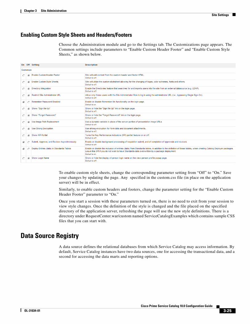
Chapter 3 Site AdministrationSite Settings
Enabling Custom Style Sheets and Headers/Footers
Choose the Administration module and go to the Settings tab. The Customizations page appears. The Common settings include parameters to “Enable Custom Header Footer” and “Enable Custom Style Sheets,” as shown below.
To enable custom style sheets, change the corresponding parameter setting from “Off” to “On.” Save your changes by updating the page. Any specified in the custom.css file (in place on the application server) will be in effect.
Similarly, to enable custom headers and footers, change the parameter setting for the “Enable Custom Header Footer” parameter to “On.”
Once you start a session with these parameters turned on, there is no need to exit from your session to view style changes. Once the definition of the style is changed and the file placed on the specified directory of the application server, refreshing the page will use the new style definitions. There is a directory under RequestCenter.war/custom named ServiceCatalogExamples which contains sample CSS files that you can start with.
Data Source RegistryA data source defines the relational databases from which Service Catalog may access information. By default, Service Catalog instances have two data sources, one for accessing the transactional data, and a second for accessing the data marts and reporting options.
3-25Cisco Prime Service Catalog 10.0 Configuration Guide
OL-31034-01
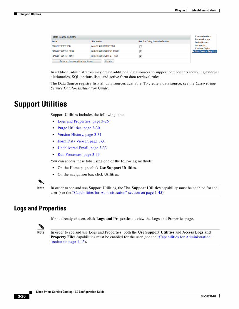
Chapter 3 Site Administration Support Utilities
In addition, administrators may create additional data sources to support components including external dictionaries, SQL options lists, and active form data retrieval rules.
The Data Source registry lists all data sources available. To create a data source, see the Cisco Prime Service Catalog Installation Guide.
Support UtilitiesSupport Utilities includes the following tabs:
• Logs and Properties, page 3-26
• Purge Utilities, page 3-30
• Version History, page 3-31
• Form Data Viewer, page 3-31
• Undelivered Email, page 3-33
• Run Processes, page 3-33
You can access these tabs using one of the following methods:
• On the Home page, click Use Support Utilities.
• On the navigation bar, click Utilities.
Note In order to see and use Support Utilities, the Use Support Utilities capability must be enabled for the user (see the “Capabilities for Administration” section on page 1-45).
Logs and PropertiesIf not already chosen, click Logs and Properties to view the Logs and Properties page.
Note In order to see and use Logs and Properties, both the Use Support Utilities and Access Logs and Property Files capabilities must be enabled for the user (see the “Capabilities for Administration” section on page 1-45).
3-26Cisco Prime Service Catalog 10.0 Configuration Guide
OL-31034-01
Chapter 3 Site AdministrationSupport Utilities
Log and Destination Folder Settings
To use Logs and Properties, the application server's log folder needs to be specified. Also a destination folder needs to be created and specified to store the compressed Zip files (containing the log and property files) until you copy and delete them. You can create and specify a different destination folder for each file type.
To specify the destination and log folders:
Step 1 Create a new destination folder (or destination folders for each file type). These folders can be anywhere.
Step 2 The destination folder or folders location and maximum size are specified in a support.properties file. There are two support.properties files—one for Request Center and one for Service Link.
These support.properties files are located in the following deployed directories:
• Request Center: RequestCenter.war\WEB-INF\classes\config\
• Service Link: ISEE.war\WEB-INF\classes\config
Note The paths above are for a Windows environment.
Open the support.properties file in a text editor.
An example support.properties file in a Windows environment is shown below.
Note For the Request Center support.properties file, only the Request Center entries are used; the Service Link entries are ignored. For the Service Link support.properties file, only the Service Link entries are used; the Request Center entries are ignored.
3-27Cisco Prime Service Catalog 10.0 Configuration Guide
OL-31034-01
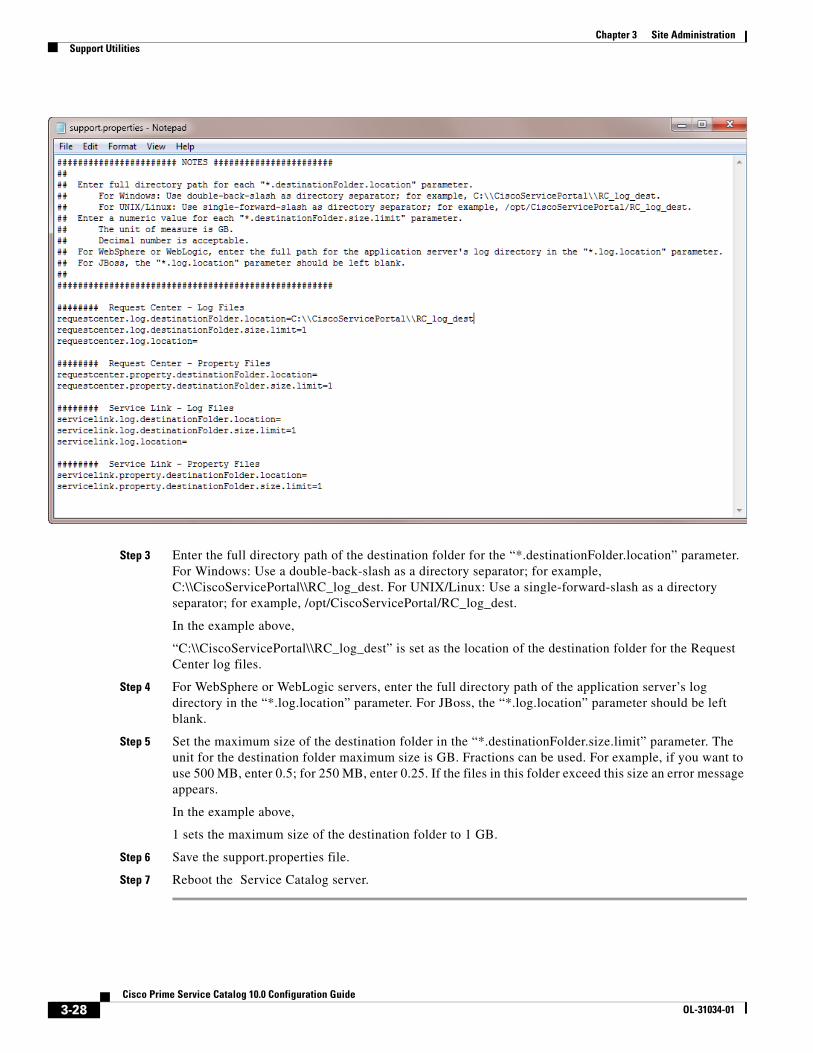
Chapter 3 Site Administration Support Utilities
Step 3 Enter the full directory path of the destination folder for the “*.destinationFolder.location” parameter. For Windows: Use a double-back-slash as a directory separator; for example, C:\\CiscoServicePortal\\RC_log_dest. For UNIX/Linux: Use a single-forward-slash as a directory separator; for example, /opt/CiscoServicePortal/RC_log_dest.
In the example above,
“C:\\CiscoServicePortal\\RC_log_dest” is set as the location of the destination folder for the Request Center log files.
Step 4 For WebSphere or WebLogic servers, enter the full directory path of the application server’s log directory in the “*.log.location” parameter. For JBoss, the “*.log.location” parameter should be left blank.
Step 5 Set the maximum size of the destination folder in the “*.destinationFolder.size.limit” parameter. The unit for the destination folder maximum size is GB. Fractions can be used. For example, if you want to use 500 MB, enter 0.5; for 250 MB, enter 0.25. If the files in this folder exceed this size an error message appears.
In the example above,
1 sets the maximum size of the destination folder to 1 GB.
Step 6 Save the support.properties file.
Step 7 Reboot the Service Catalog server.
3-28Cisco Prime Service Catalog 10.0 Configuration Guide
OL-31034-01
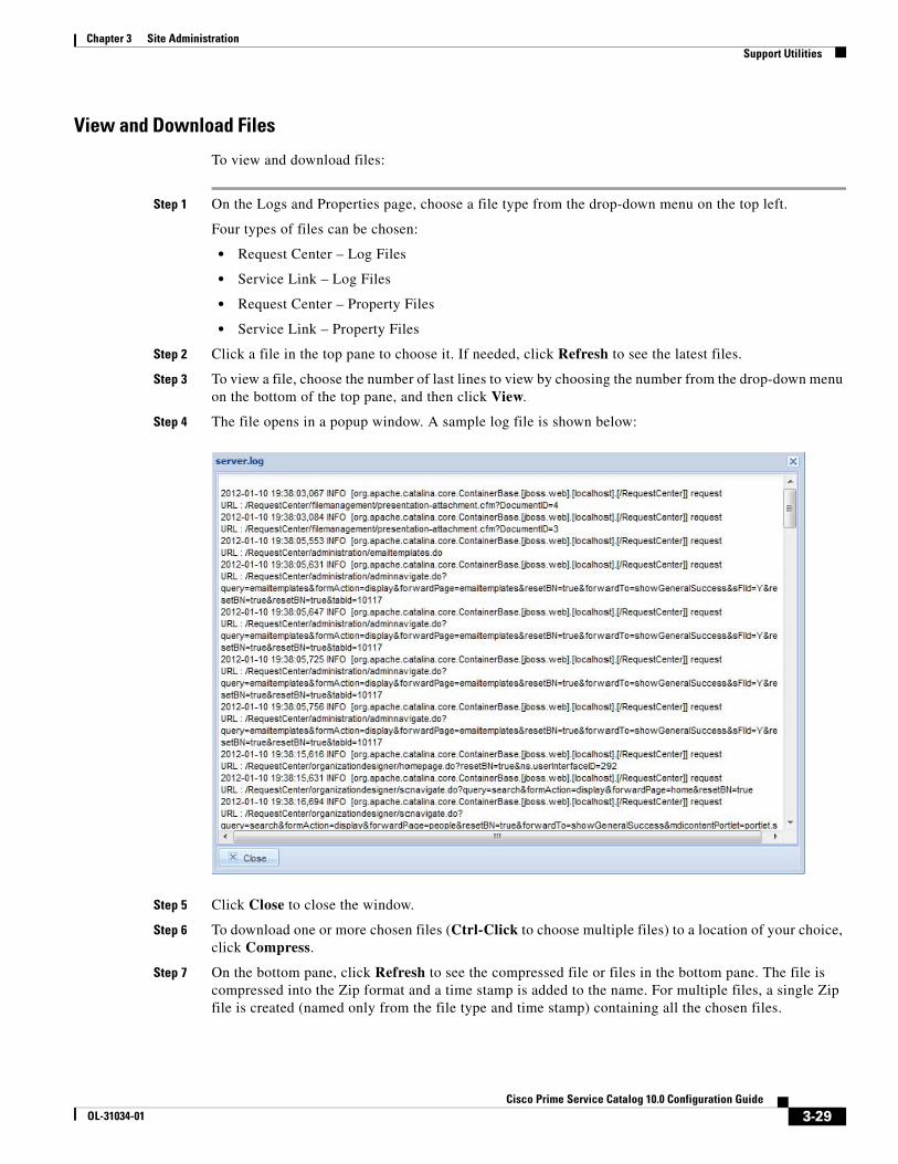
Chapter 3 Site AdministrationSupport Utilities
View and Download Files
To view and download files:
Step 1 On the Logs and Properties page, choose a file type from the drop-down menu on the top left.
Four types of files can be chosen:
• Request Center – Log Files
• Service Link – Log Files
• Request Center – Property Files
• Service Link – Property Files
Step 2 Click a file in the top pane to choose it. If needed, click Refresh to see the latest files.
Step 3 To view a file, choose the number of last lines to view by choosing the number from the drop-down menu on the bottom of the top pane, and then click View.
Step 4 The file opens in a popup window. A sample log file is shown below:
Step 5 Click Close to close the window.
Step 6 To download one or more chosen files (Ctrl-Click to choose multiple files) to a location of your choice, click Compress.
Step 7 On the bottom pane, click Refresh to see the compressed file or files in the bottom pane. The file is compressed into the Zip format and a time stamp is added to the name. For multiple files, a single Zip file is created (named only from the file type and time stamp) containing all the chosen files.
3-29Cisco Prime Service Catalog 10.0 Configuration Guide
OL-31034-01

Chapter 3 Site Administration Support Utilities
Note If the same file is compressed again, a new file with a different time stamp is created—the previously compressed file is not overwritten.
Step 8 On the bottom pane, click the Download icon ( ) for a single file.
Step 9 A File Download dialog box appears. Click Save.
Step 10 A Save As dialog box appears allowing you to save the file to a location of your choice.
Step 11 Navigate to the location you want and click Save.
Step 12 After saving the file or files, you can delete the chosen compressed file or files (Ctrl-Click to choose multiple files) from the bottom pane by clicking Delete.
See the “Adjusting Columns” section on page 3-32 to resize, move, sort, and hide columns in the top and bottom panes of the Logs and Properties page.
Purge UtilitiesChoose Administration > Utilities > Purge Utilities to view the Purge Utilities page.
Note In order to see and use Purge Utilities, both the Use Support Utilities and Access Purge Utilities capabilities must be enabled for the user (see the “Capabilities for Administration” section on page 1-45).
The three types of purge utilities are described below:
• Requisition – The requisition purge utility deletes requisitions older than a chosen date or that meet other user-specified criteria. This allows the application administrator to remove test requisitions before deleting test users and sample services. The requisition purge utility may also be used for housekeeping purposes to control the database size, for example, to delete older requisitions that no longer need to be retained. However, the requisition purge utility is not optimized for mass data deletion and should be used with caution to avoid impacting the system response times for other application users.
The requisition purge utility removes those requisitions that meet the purge filter criteria and all transactional data associated with those requisitions, including tasks and Service Link messages. Results from the actual requisition purge are also appended to the LogPurge table in the RequestCenter database.
• Service Link – The Service Link purge utility removes nsXML messages from the database. Since these messages can be quite large (depending on the complexity of the service form and content type option used to configure the agent), removing the messages greatly reduces the database size required to hold Service Link-related data. External messages remain unchanged.
• Business Engine – The Business Engine purge utility removes temporary data from the database related to workflow processing. This data are no longer used in the product and can be removed to reduce the database size. Executing this purge utility periodically could also provide overall performance improvement.
The Business Engine purge utility may require an hour or more to execute if you have a large database. Hence the purge should be done during a low activity time window. A practice run is recommended on a sandbox environment to establish how long the utility will run for your database.
3-30Cisco Prime Service Catalog 10.0 Configuration Guide
OL-31034-01
Chapter 3 Site AdministrationSupport Utilities
To perform a purge:
Step 1 Click the radio button next to Requisition, Service Link, or Business Engine to choose the type of purge.
Step 2 Enter date ranges to filter the data to be purged. For a Requisition purge, you may also optionally filter the data by Requisition ID, Requisition Status, and Service Name.
Step 3 (Optional) Before performing a Requisition purge, click Analyze to perform a “dry run” purge. Click OK to continue. This allows you to see the requisitions that would be removed without actually deleting anything. This can serve as a validation for the filter criteria in effect. Go to Step 7.
Step 4 Click Purge to start the purge.
Step 5 Click Yes to continue.
Step 6 The purge starts. Click OK.
Step 7 Click the Refresh button ( ) after some time. When the purge or analysis completes, a new date/time entry is added in the Purge History pane at the top of the list. You must click the Refresh button ( ) to see the new purge completion date/time entry.
Step 8 In the Purge History pane, click the purge completion date/time entry to see purge or analysis information in the Log Content pane on the right.
Step 9 If you did a Requisition purge analysis (Step 3), go to Step 4 above to start the actual purge.
Performance Considerations for Executing Purge
Purging can be performed while the Service Catalog application is up and running. However, you should limit the amount of purge activities during peak hours, and instead plan on doing large volume purging during off hours.
The purge utilities are also available as SQL scripts or batch programs that can be scheduled for execution. See the “Performing Application Housekeeping” section on page 5-10 for more information.
Version HistoryClick Administration > Utilities > Version History to view the Version History page.
Note In order to see and use Version History, both the Use Support Utilities and Access Version History capabilities must be enabled for the user (see the “Capabilities for Administration” section on page 1-45).
The Version History page displays the current product version number of Service Catalog and a version history of build upgrades and patches.
Form Data ViewerClick Administration > Utilities > Form Data Viewer to view the Form Data Viewer page.
3-31Cisco Prime Service Catalog 10.0 Configuration Guide
OL-31034-01
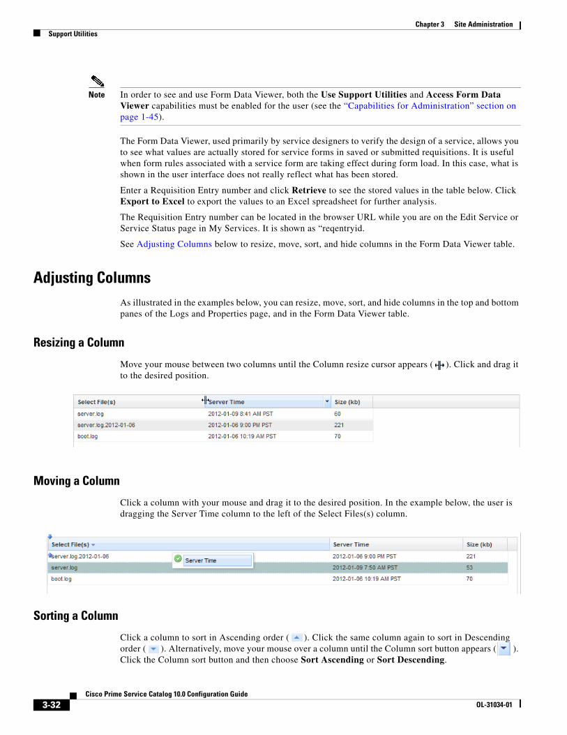
Chapter 3 Site Administration Support Utilities
Note In order to see and use Form Data Viewer, both the Use Support Utilities and Access Form Data Viewer capabilities must be enabled for the user (see the “Capabilities for Administration” section on page 1-45).
The Form Data Viewer, used primarily by service designers to verify the design of a service, allows you to see what values are actually stored for service forms in saved or submitted requisitions. It is useful when form rules associated with a service form are taking effect during form load. In this case, what is shown in the user interface does not really reflect what has been stored.
Enter a Requisition Entry number and click Retrieve to see the stored values in the table below. Click Export to Excel to export the values to an Excel spreadsheet for further analysis.
The Requisition Entry number can be located in the browser URL while you are on the Edit Service or Service Status page in My Services. It is shown as “reqentryid.
See Adjusting Columns below to resize, move, sort, and hide columns in the Form Data Viewer table.
Adjusting ColumnsAs illustrated in the examples below, you can resize, move, sort, and hide columns in the top and bottom panes of the Logs and Properties page, and in the Form Data Viewer table.
Resizing a Column
Move your mouse between two columns until the Column resize cursor appears ( ). Click and drag it to the desired position.
Moving a Column
Click a column with your mouse and drag it to the desired position. In the example below, the user is dragging the Server Time column to the left of the Select Files(s) column.
Sorting a Column
Click a column to sort in Ascending order ( ). Click the same column again to sort in Descending order ( ). Alternatively, move your mouse over a column until the Column sort button appears ( ). Click the Column sort button and then choose Sort Ascending or Sort Descending.
3-32Cisco Prime Service Catalog 10.0 Configuration Guide
OL-31034-01

Chapter 3 Site AdministrationSupport Utilities
Hiding or Showing Columns
Move your mouse over a column until the Column sort button appears ( ). Click the Column sort button, choose Columns, and then check the check boxes of the columns you want to display.
Undelivered EmailUndelivered Email utility provides a list of authorization, review, or notification emails theat were undelivered to the recipient. You can view, resend, or delete the undelivered emails appropriately.
To resend undelivered emails:
Step 1 Select Administration > Utilities > UnDelivered Email.
Step 2 Click the Requisition ID or use the Search tab to search for the requisition.
Step 3 Review the email in the Message window
Step 4 Click Resend.
Run ProcessesYou can use this utility to migrate historical requisitions to the historical data tables on an adhoc basis. The manual migration process in an off-peak period will reduce the system overhead.
The values that are configured in newscale.properties file are displayed in the cut-off date, batch size, and maximum number of requisitions fields accordingly. You can further edit the settings and then click Start to enable the scheduler.
3-33Cisco Prime Service Catalog 10.0 Configuration Guide
OL-31034-01

Chapter 3 Site Administration Support Utilities
The processing rate and duration vary based on the average size of the requisitions. Work with your database administrator to perform trial runs and estimate the time required for the first-time execution, before executing the migration process in your production environment. For more information, see Performing Application Housekeeping, page 5-10.
To start the migration process:
Step 1 Select Administration > Utilities > Run Processes.
Step 2 Select a cut-off date using the calendar.
Step 3 You can also choose to enter a batch size and the maximum number of requisitions that you can process.
Step 4 Click Start to begin the migration process.
Note Ensure that the Enable Historical Requisitions Scheduler setting in Administration > Settings tab is turned off. You can choose to process historical migration either by enabling the historical scheduler in or by using the Run Process Utility.
To terminate the migration process:
Step 1 Select Administration > Utilities > Run Processes.
Step 2 Click Stop to terminate migration process that was enabled using the scheduler or the utilities.
Recommendation for Datamart
Consider the following when configuring the historical requisition partitioning feature if you have a reporting module:
• Historical transaction data are not extracted by the ETL process.
• ETL process is normally scheduled to run on a frequent basis. Hence requisition data would have been captured into Datamart prior to their migration to the historical tables. To ensure there is no data loss in the Datamart, always set the historical requisition retention period to be greater than the frequency of the ETL process. For example, if ETL is set to run every 30 days, the historical requisition retention period should be set to 31 days or more.
• The process that migrates historical transaction data is automatically put on hold when it detects that the most recent ETL process timestamp is earlier than the cutoff date. For example, if the last ETL execution was on May 1st 12pm and the migration is going to select requisitions completed before May 1st 12:30pm, the migration process will exit immediately. This ensures that data are kept in the current transaction tables for extraction into Datamart before they get migrated.
• The historical data will not be recoverable in the Datamart once they have been purged. If your organization has the need to rebuild Datamart occasionally to capture backdated data (for example, making a dictionary or service reportable after the fact), the changes will not take effect on historical transactions by re-running the ETL process. To ensure such Datamart rebuild process is still possible, configure the data retention period to a duration that has provisions for backdated changes.
3-34Cisco Prime Service Catalog 10.0 Configuration Guide
OL-31034-01

Chapter 3 Site AdministrationSupport Utilities
In addition, the Datamart should no longer be emptied in a rebuild process for the reason above. Only the portion of data that are still available in the current transaction tables can be deleted and re-inserted into the Datamart during the re-execution of ETL.
3-35Cisco Prime Service Catalog 10.0 Configuration Guide
OL-31034-01

Chapter 3 Site Administration Support Utilities
3-36Cisco Prime Service Catalog 10.0 Configuration Guide
OL-31034-01

CiOL-31034-01
C H A P T E R 4
Custom Style Sheets• Overview, page 4-1
• Custom Style Sheets, page 4-1
• Style Summary and Recommended Practices, page 4-11
• Custom Headers and Footers, page 4-18
OverviewThis chapter describes the capabilities provided to customize the appearance of the Service Catalog web pages. This customization is accomplished through the use of Cascading Style Sheets (css) to format those web pages as well as the addition of a custom header and footer.
These capabilities allow designers to customize the appearance of all customer-facing modules of Service Catalog. The pages which may be customized include:
• Pages displayed in the Cisco Prime Service Catalog My Services, Service Catalog, and Service Manager modules including service forms dynamically generated, based on definitions specified via Service Designer
• The portals for Reporting and Advanced Reporting
• The login pages
• Preconfigured and custom portal pages in the Service Portal solution
The appearance of modules used by service designers and administrators to configure and manage Service Catalog cannot be customized. These modules include Service Item Manager, Service Designer, Organization Designer, Administration, Catalog Deployer, Portal Designer, and Service Link.
Custom Style Sheets
OverviewContents of the Service Catalog application are presented as web pages formatted using HTML. Cascading Style Sheets (css) offer the ability to customize the appearance of web pages by changing the definition of styles used to display the pages, rather than having to edit the pages themselves.
4-1sco Prime Service Catalog 10.0 Configuration Guide
Chapter 4 Custom Style Sheets Custom Style Sheets
Custom styles allow designers to customize Service Catalog web pages, headers and footer. Custom styles may be applied to all users of an application instance, or different styles may be applied to users based on their home organizational unit.
Prerequisites • You must have access to the file system of the application server, specifically to the “custom”
directory of the RequestCenter.war archive and its subdirectories. You need both read and write access to this directory and to its subdirectories.
• You must have a user role which includes the Administration capability to “Manage Global Settings” in order to turn on or off the use of custom style sheets, headers, and footers.
• Browser page caching must be turned off in order for you to test style sheet changes.
• Ideally, you should have access to an application instance where you can test your changes without disturbing the work of other analysts or developers.
• A style sheet editor and other editing tools are highly recommended, but not required.
Customizing Built-In ModulesThe procedure below gives the basic steps to follow in order to customize the appearance of styles used in the built-in modules, namely My Services, Service Catalog, Service Manager, and Reporting. Additional details on these styles are given in the following sections.
1. Create a directory on the application server, under the RequestCenter.war/custom directory, where the files required for the custom styles will reside. The directory will typically have an images subdirectory, for any custom images. The directory name should indicate the tenant/organization name to which the styles will apply.
2. If you use the Service Catalog module as the end user module, copy all the files located in the custom/ServiceCatalogExamples directory into the new directory created in Step 1. If you use My Services module, copy all the files located in the custom/CustomExamples instead. Location of this archive will vary, based on your application server and installation setting.
3. In the new directory, remove the "example_" prefix of files in the directory as well as in the application directory under it. Modify the css files and add image files as needed to tailor the look and feel of the user interface as needed.
4. Use the Custom Styles page in the Administration module to define the style, specify the directory on which required files reside, and assign the organizations to which the style applies.
5. Use the Settings page in the Administration module to turn on custom stylesheets.
6. Restart the browser session of Service Catalog—the pages should appear with the customizations applicable to the logged in user. You must exit and restart the Service Catalog session when custom stylesheets are initially activated. To test subsequent changes to the styles, it is sufficient to copy the revised style sheet to the application server and refresh the current page. The new styles will be applied, provided page caching is not in effect.
Caution Once you change the Administration Settings to use custom stylesheets, the custom.css file should be present on the specified directory. If the file is not present, Service Catalog will use its standard styles. Similarly, if the option to use a custom header or footer is turned on, the corresponding files must be present on the specified directory.
4-2Cisco Prime Service Catalog 10.0 Configuration Guide
OL-31034-01

Chapter 4 Custom Style SheetsCustom Style Sheets
Customizing User-Defined PortalsJust like Service Catalog, My Services and other built-in modules, the Service Portal modules can be customized for different organizational units through style sheets. The custom styles are maintained in a different style sheet from the other built-in modules to give you greater flexibility in how you present the Portal Manager modules.
The Service Portal solution also offers different themes that affect the colors of portlets on a portal page. You can allow users to choose their own themes, or give this ability only to portal designers. See the Cisco Prime Service Catalog Designer Guide for more information regarding portal page themes.
The custom stylesheet for Service Portal module is located in the same custom/ServiceCatalogExamples or custom/CustomExamples directory as Service Catalog and is enabled/disabled along with it.
1. Obtain a copy of the file example_portal-custom-header.css from the custom directory of the Service Catalog web archive (RequestCenter.war).
2. Name the copied file as portal-custom-header.css. Change the styles in the file according to the guidelines given in the next section of this chapter.
3. Copy this file into the custom directory created for the tenant/organization (see Customizing Built-In Modules, page 4-2, Step 1) along with any images used.
Example
The following example describes how to modify the logo, product name and background color in the portal header:
.reboot2 .xwtBackgroundSimplified {background: transparent !important;}/*style to modify logo image*/.reboot2 .applicationHeader17 .applicationLogoImage {background: url("images/MyCo_logo92x33.gif") no-repeat transparent !important;/*background-repeat: no-repeat;background-position: 0 .514em;background-size:75px auto;padding-left: 3em!important;padding-right: 5em!important;*/height: 33px !important;width:92px !important;/* Note: un-comment display property to hide the Product Logo if needed *//*display:none !important;*/}/* This style is used to display or hide the Product Title in Portal modulesSee Also: .applicationHeaderAppSubTitle, .applicationLogoImage, .applicationHeaderLogoText style - which will be the new style used to display branding logo*/.reboot2 .applicationHeader17 .applicationHeaderAppName {visibility: hidden;}
Defining a Custom StyleTo start using custom style sheets or headers and footers:
Step 1 Log in to Service Catalog, choose the Administration module, and go to the Settings tab.
The Customizations page appears.
4-3Cisco Prime Service Catalog 10.0 Configuration Guide
OL-31034-01

Chapter 4 Custom Style Sheets Custom Style Sheets
Step 2 At the right side of the screen, choose the Custom Style option from the option list.
Step 3 Click Add to create a new style.
The Custom Style Properties page appears.
Step 4 Fill in the properties as follows:
• Style Name should reflect the organizations to which the styles will apply.
• One style may be designated as the Default. If a default is specified, it is used for any user whose home organization (OU) has not be assigned a style. If no default is specified, the default Service Catalog style sheets is used.
• If a hierarchical structure is reflected in the organizations, you may specify that a style is inherited by all child OUs of a parent.
• You may choose the Style Directory from any directory under RequestCenter.war/custom. The directory must exist before you can create the style.
• A Description is optional but recommended.
Step 5 Click Add to create the style. You can then edit the style, to specify the organizations to which the style applies.
Step 6 Click Add in the Associated Organizational Units pane. The Organizational Unit Search window appears. Choose one or more business units.
Step 7 You may edit the style definition or the business units to which it applies at any time.
Enabling Custom Style Sheets and Headers/FootersChoose the Administration module, and go to the Settings tab. The Customizations page appears. The Common settings include parameters to “Enable Custom Header Footer” and “Enable Custom Style Sheets”, as shown below.
4-4Cisco Prime Service Catalog 10.0 Configuration Guide
OL-31034-01

Chapter 4 Custom Style SheetsCustom Style Sheets
To enable custom stylesheets, change the corresponding parameter setting from “Off” to the left “On” button. Save your changes by updating the page. When you start a new Service Catalog session, any custom styles specified in the custom.css file (in place on the application server) will be in effect.
Similarly, to enable custom headers and footers, change the parameter setting for the “Enable Custom Header Footer” parameter to “On”.
Once you start a Service Catalog session with these parameters turned on, there is no need to exit from your session to view style changes. Once the definition of the style is changed and the file placed on the specified directory of the application server, refreshing the page will use the new style definitions.
Modifying Customizations with Browser Cache EnabledIf the Browser Cache setting is enabled in the Administration Settings, changes made to custom style sheets, headers and footers will not take effect until the browser cache has been deleted. To prompt the application users to delete their browser cache, follow the instructions in the “Browser Cache Setting” section on page 3-12 to increment the browser cache version.
Customizing Styles for Service Catalog ModuleFiles in the custom\ServiceCatalogExamples directory are available if you want to do more extensive customization of the UI. There are three main files to start with:
• before.html – The content of this file is prepended to the <body> of the HTML document. You can use this file to override product strings before they are displayed. For example, the product name in the header uses string ID 15162, so you can make the product show “Small Company” by inserting this block into before.html:
<script>serviceCatalogMessage.putString("15162", 'My Company');</script>
Use Firebug or other web developer tools to examine the HTML code of the Service Catalog module. You will see other strings that you can override.
• head.html – The content of this file is injected into the end of the (head) section of the HTML document. You can override the colors and styles specified by the various HTML classes and elements on the web page. For example, change the color settings for the My Company "homeslider" to something different:
<style>.homeslider .blocks.block1 {background-color: #9E6F9A; //#2B6F9A;background-image: linear-gradient(to bottom, #985DC2, #B6115E); // #258DC2, #04415E);background-repeat: repeat-x;}.homeslider .blocks.block2 {background-color: #9E6F9A; //#2B6F9A;background-image: linear-gradient(to bottom, #D486C0, #B43557); // #6486C0, #213557);
4-5Cisco Prime Service Catalog 10.0 Configuration Guide
OL-31034-01

Chapter 4 Custom Style Sheets Custom Style Sheets
background-repeat: repeat-x;}.homeslider .blocks.block3 {background-color: #9E6F9A; //#2B6F9A;background-image: linear-gradient(to bottom, #EE86C0, #BE3157); // #7B86C0, #2B3157);background-repeat: repeat-x;}</style>
• after.html – The content in this file is appended at the end of the html (body).
Here is a quick example on how to change the default Cisco Logo to some other company logo in the head.html file, as it is a style override:
<style>.navbar-inner {background-color: transparent;background-image: none;filter: progid:DXImageTransform.Microsoft.gradient(enabled=false); // disable gray header bar in IE}.navbar .nav {color: #333;text-shadow: none;}.navbar .nav ) li ) a {color: #333;text-shadow: none;}.psc-goto-cart {color: #333 !important;}.psc-top-icon {border:2px solid #333;background-color: #333;}.navbar .brand {float: left;display: block;height: 2em;background-image: url("/RequestCenter/custom/MyCo/images/MyCo_logo92x33.gif");background-repeat: no-repeat;background-position: 0 .514em;background-size:75px auto;padding-left: 3em!important;padding-right: 5em!important;
font-size: 1.571em;line-height: 2.28em;color: #333;text-shadow: none;}</style>
4-6Cisco Prime Service Catalog 10.0 Configuration Guide
OL-31034-01

Chapter 4 Custom Style SheetsCustom Style Sheets
Customizing Styles for MyServices ModuleThe custom\CustomExamples directory includes files you can use as starting points for customizations of My Services module. Directory contents are summarized in the table below.
The CustomExamples/example.css and example_portal-custom-header.css files (the templates for your custom.css and portal-custom-header.css) are formatted as a standard cascading style sheet file and includes comments to guide you in choosing styles to modify. These comments include brief descriptions of where and how a particular style is used; however, some experimentation is required to fine tune customizations.
The original definitions for customized styles should be retained as comments in the style sheet. This practice is recommended, in case a customized change needs to be backed out and to maintain traceability to the original page appearance.
Page Headers
The page header for the end-user facing modules is governed by the following styles:
custom (folder) Contents Description
CustomExamples Folder which contains starting points for custom styles, header, and footer
images Folder which contains the images currently used by Service Catalog styles which may be replaced via custom style sheets
common_task_bg.gif Background for the Common Tasks pane
headerGradient.gif Background for header styles—style which appear at the top of each portlet or pane
logo_bottom.gif (Deprecated)
lvl1_nav_shade.gif Background for the tabs which provide top-level navigation through the options available in each Service Catalog module
lvl3_nav_shade.gif Background for level 3 headers—also recommended for page footers
mark.gif Denotes a mandatory field on a service form
orange_bullet.gif Common Tasks bullet
orange_li_bullet.gif (Not used in example custom.css)
page_footer_shade.gif Gif available for page footer shading
PopupHeaderGradient.gif (Not used in example custom.css)
requiredMark.gif Denotes a mandatory field on all user interface pages other than service forms
tfoot_shade.gif (Not used in example custom.css)
example.css Sample file, mirrors default Service Catalog settings to start with, with solid color replacing gradients
example_portal-custom-header.css Sample file, mirrors default Portal Manager header area settings
example_footer.html Starting point for developing custom footer
example_header.html Starting point for developing custom header
4-7Cisco Prime Service Catalog 10.0 Configuration Guide
OL-31034-01

Chapter 4 Custom Style Sheets Custom Style Sheets
• lvl1_nav (for built-in modules only): The “Level1 Navigation Bar” provides the background for the application module drop-down menu and menu bar. The application name cannot be modified but can be hidden using the “lvl1_nav_title” style if desired.
• header (for user-defined modules only): The header style is used with portal modules that are created/maintained using Portal Designer. The usage is similar to the lvl1_nav above.
• headerlogo, leftheaderlogo: The two header logo styles provide flexibility in placing the logo at either the left or right hand side of the header. When the left logo is used, the background property of the application name must be set to none. The styles governing the application module menu may also be modified so that it can be positioned at the right-hand corner.
Navigation Bars
By default, most of the navigation bars simply specify a background color. However, as with any other background designated in the style sheet, this can be changed to use a banner or graphic.
Other portions of My Services pages use decorations as headers and footers for portions of the page. For example, the “Level3 Navigation” (lvl3_nav) and footer styles delimit the page body of the My Services home page, as shown in the illustration above. They should be changed together.
The “Breadcrumb Navigation” (bread_nav) provides the background for the breadcrumb area.
Buttons
Buttons appear on service forms and through the Service Catalog user interface. The appearance of buttons is governed via the style button.primary. The default style for primary buttons is set to use bold face and can be modified to have more prominent styles if necessary.
Service Forms
The appearance of the fields and captions on service forms is governed by a set of styles, as shown below and summarized in the following table. All .form styles should be changed in unison.
1 Primary buttons
1 1
Style Usage
shortHeader The dictionary caption
subhead The bar delineating the start of each dictionary displayed with a caption
.formReq_border Blank space to the left of the field label, and the line separating one field from the next
.formLabel The field label
.formElement Formatting for the input element for the field's HTML representation
4-8Cisco Prime Service Catalog 10.0 Configuration Guide
OL-31034-01
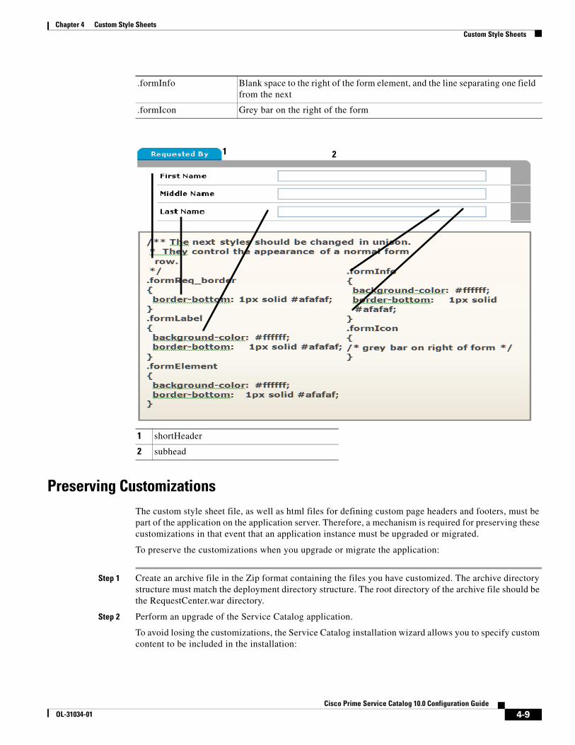
Chapter 4 Custom Style SheetsCustom Style Sheets
Preserving CustomizationsThe custom style sheet file, as well as html files for defining custom page headers and footers, must be part of the application on the application server. Therefore, a mechanism is required for preserving these customizations in that event that an application instance must be upgraded or migrated.
To preserve the customizations when you upgrade or migrate the application:
Step 1 Create an archive file in the Zip format containing the files you have customized. The archive directory structure must match the deployment directory structure. The root directory of the archive file should be the RequestCenter.war directory.
Step 2 Perform an upgrade of the Service Catalog application.
To avoid losing the customizations, the Service Catalog installation wizard allows you to specify custom content to be included in the installation:
.formInfo Blank space to the right of the form element, and the line separating one field from the next
.formIcon Grey bar on the right of the form
1 shortHeader
2 subhead
1 2
4-9Cisco Prime Service Catalog 10.0 Configuration Guide
OL-31034-01

Chapter 4 Custom Style Sheets Custom Style Sheets
Step 3 Run the Service Catalog installation wizard as described in the Cisco Prime Service Catalog Installation Guide, using the Advanced Installation type.
Step 4 On the Application Server Configuration page, click Advanced Options.
Step 5 The Advanced Options dialog box appears, as shown below.
Step 6 Check Custom content? as shown above.
Step 7 Enter the full path to the Custom content archive including the name of the archive, or click Browse to locate and choose the custom content archive.
Step 8 Click Close.
Step 9 Continue with the installation as described in the Cisco Prime Service Catalog Installation Guide.
Step 10 While the Service Catalog installation wizard completes the installation, it extracts your custom content archive into the application deployment directory structure.
Known Errors and OmissionsThe online help files provided for Service Catalog cannot be customized.
Unknown Errors and OmissionsIt is possible that some styles used in Service Catalog pages are not included in the CustomExamples/example.css file. If you find such an omission, please report it to the Cisco Technical Assistance Center (TAC).
A temporary workaround may be possible. View the source for the generated page, noting the class or id of the sections to which the style is to be applied. If this class or id uniquely identified the object whose appearance you want to change, include an appropriate style in your custom stylesheet, or add an appropriate attribute to the style definition. Care should be taken if you elect to use this approach, as any additions to the custom stylesheet may not be supported in subsequent releases.
4-10Cisco Prime Service Catalog 10.0 Configuration Guide
OL-31034-01

Chapter 4 Custom Style SheetsStyle Summary and Recommended Practices
Upgrading from Previous VersionsThe styles used in this version of Service Catalog may have been modified from those used in previous versions. These changes not only update the appearance of the pages but also address performance and consistency issues that had been raised in previous releases.
Style Summary and Recommended Practices
Style Summary – Built-In ModulesThe table below summarizes styles available in the custom.css.
Style/Class Name Comment
Body and Global Styles
body
#lvl3_nav
#headerlogo Right-hand logo
#leftheaderlogo Left-hand logo
#lvl1_nav_title Application name
#footer
.levelTwoNavigation Tab selection
table#nsLayout.rightMenu td#layoutright
Navigation Styles
#lvl1_nav
#lvl1_nav span #lvl1_nav a
#llvl1_nav a:hover
.menuDivider
#lvl2_nav
#lvl2_nav a
#lvl2_nav td.active
h2#title_nav
#bread_nav
#bread_nav a
#logobottom Deprecated (dummy image used)
Tab Navigation Control Styles
.levelTwoNavigation a
.tabNavigation a
.levelTwoNavigation a:hover
.tabNavigation a:hover
4-11Cisco Prime Service Catalog 10.0 Configuration Guide
OL-31034-01

Chapter 4 Custom Style Sheets Style Summary and Recommended Practices
.levelTwoNavigation a.selected
.tabNavigation a.selected
.levelTwoNavigation a.selected:hover
.tabNavigation a.selected:hover
.propertyTabNavigation a
#levelTwoTabDiv img Left and right-edge images on tab button
.levelTwoNavigation div.levelTwoTab
.levelTwoNavigation a
My Services Service Items Tab Styles
.x-grid3-row Background-color for grid row
.x-grid3-row TD Font for grid row
.x-grid3-row-alt Background color for alternate row
.x-grid3-hd-row td Font for grid header
ul.x-tab-strip-top Background color for tabs
.x-tree-node A SPAN Font for tree
Header and Title Styles
div.longHeader div.shortHeader
div.longHeader h4 div.shortHeader h4 div.longHeader span div.shortHeader span
div.subHeader
h4.header
h4.header span
Button Styles
button input.primary input.secondary input.disabled
button.primary input.primary
button.secondary button.help input.secondary
button.disabled input.disabled
Catalog and Service Display Styles
table.browser
table.browser td.categoryImage Pixel sizes for the Service Catalog and category images
Style/Class Name Comment
4-12Cisco Prime Service Catalog 10.0 Configuration Guide
OL-31034-01
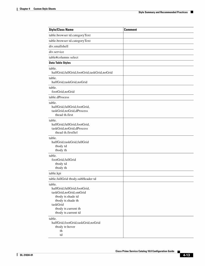
Chapter 4 Custom Style SheetsStyle Summary and Recommended Practices
table.browser td.categoryText
table.browser td.categoryText
div.smallshell
div.service
table#columns select
Data Table Styles
table. halfGrid,fullGrid,footGrid,taskGrid,noGrid
table. halfGrid,taskGrid,noGrid
table. footGrid,noGrid
table.dProcess
table. halfGrid,fullGrid,footGrid, taskGrid,noGrid,dProcess thead th.first
table. halfGrid,fullGrid,footGrid, taskGrid,noGrid,dProcess thead th.firstSel
table. halfGrid,taskGrid,fullGrid tbody td tbody th
table. footGrid,fullGrid tbody td tbody th
table.kpi
table.fullGrid tbody.subHeader td
table. halfGrid,fullGrid,footGrid, taskGrid,noGrid,smGrid tbody tr.shade td tbody tr.shade th taskGrid tbody tr.current th tbody tr.current td
table. halfGrid,footGrid,taskGrid,noGrid tbody tr:hover th td
Style/Class Name Comment
4-13Cisco Prime Service Catalog 10.0 Configuration Guide
OL-31034-01

Chapter 4 Custom Style Sheets Style Summary and Recommended Practices
table. halfGrid,fullGrid,footGrid, taskGrid,noGrid,dProcess,smGrid thead th body.calendar table#calendar th
table. halfGrid,fullGrid,footGrid,noGrid tfoot th tfoot td
table. halfGrid,fullGrid,footGrid,noGrid tbody tr td.select tbody tr th.select
table. halfGrid,fullGrid,footGrid,noGrid tbody tr td.select + td td.select + th th.select + td th.select + th
table.fullGrid tbody.td.kvpKeyHi:hover table.fullGrid tbody.th.kvpKeyHi:hover table.fullGrid tbody.td.kvpKeyHi:hover + td.kvpValue table.fullGrid tbody.th.kvpKeyHi:hover + td.kvpValue
table.fullGrid tbody.td.kvpKeyHi table.fullGrid tbody.th.kvpKeyHi
table.fullGrid tbody td.kvpValueHi
Other Tables and Table-Related Content Styles
div.thead div tfoot
div.tsubfoot
div.detailHeader
div.detailHeader td.owi
div.tfoot input.textBox div.tsubfoot input.textBox
Comments and History Styles
table.commentstable
table.commentsTable div.commentContainer
Common Tasks and Portlet Styles
div.shell
.commonTaskCell ul.tasks.li
Style/Class Name Comment
4-14Cisco Prime Service Catalog 10.0 Configuration Guide
OL-31034-01

Chapter 4 Custom Style SheetsStyle Summary and Recommended Practices
ul.tasks
img.commontaskbullet
Normal Portlet, Form and Container Styles
div.service div.shell div.smallshell div smallShell table.halfGrid table.fullGrid table.footGrid table.taskGrid table.noGrid #treecontainer div.loginBox
Input Elements
input select
Service form text elements
input.textBox textarea
Service form textarea elements
Content-Switching Styles
ul.MDITabs li:hover
ul.MDITabs li.active
Service Form Styles
tr.error td. formReq formLabel formElement formFlex formInfo
Components of the fields defined in dictionaries used in service forms—the required symbol, the field label, the input element
tr.error td.formIcon
.formReq_border
.formLabel
.formElement
.formFlex
.formInfo
.formIcon
div#formMonitor div a
div#formMonitor div.valid
div#formMonitor div.invalid
Calendar Styles
body.calendar table#calendar td
body.calendar table#calendar td.selected
Style/Class Name Comment
4-15Cisco Prime Service Catalog 10.0 Configuration Guide
OL-31034-01
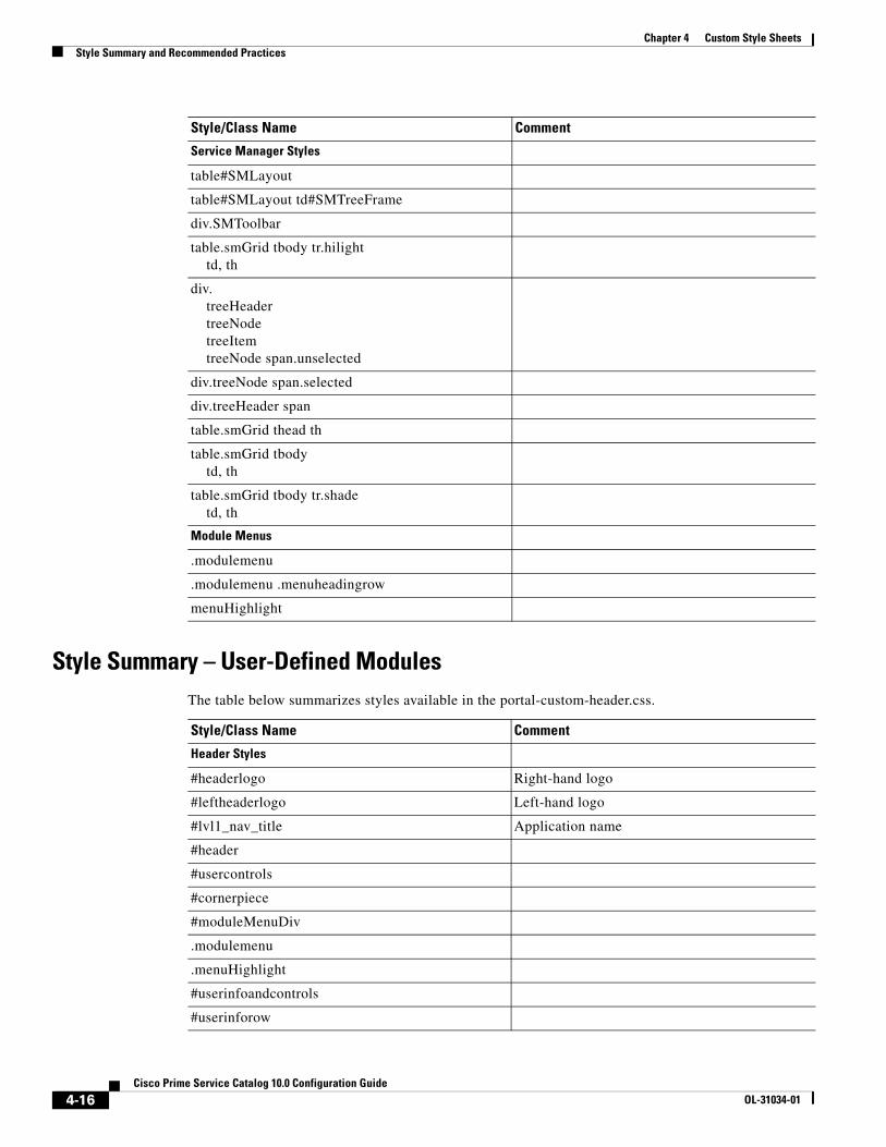
Chapter 4 Custom Style Sheets Style Summary and Recommended Practices
Style Summary – User-Defined ModulesThe table below summarizes styles available in the portal-custom-header.css.
Service Manager Styles
table#SMLayout
table#SMLayout td#SMTreeFrame
div.SMToolbar
table.smGrid tbody tr.hilight td, th
div. treeHeader treeNode treeItem treeNode span.unselected
div.treeNode span.selected
div.treeHeader span
table.smGrid thead th
table.smGrid tbody td, th
table.smGrid tbody tr.shade td, th
Module Menus
.modulemenu
.modulemenu .menuheadingrow
menuHighlight
Style/Class Name Comment
Style/Class Name Comment
Header Styles
#headerlogo Right-hand logo
#leftheaderlogo Left-hand logo
#lvl1_nav_title Application name
#header
#usercontrols
#cornerpiece
#moduleMenuDiv
.modulemenu
.menuHighlight
#userinfoandcontrols
#userinforow
4-16Cisco Prime Service Catalog 10.0 Configuration Guide
OL-31034-01
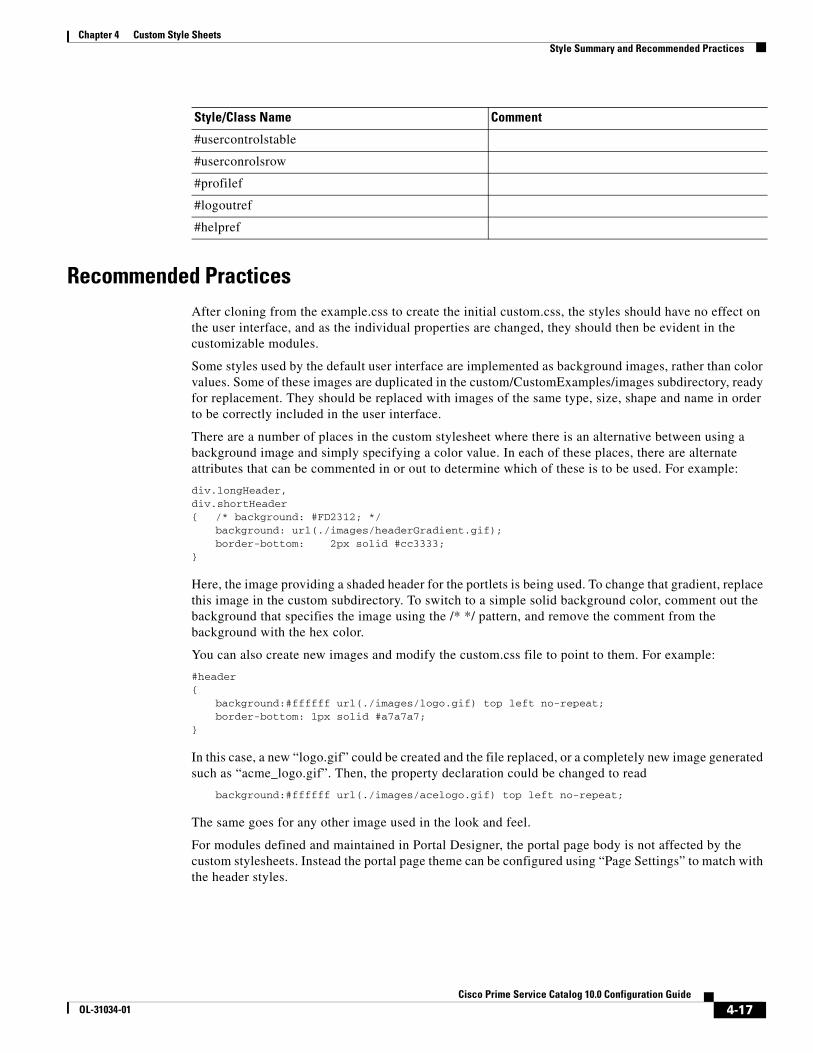
Chapter 4 Custom Style SheetsStyle Summary and Recommended Practices
Recommended PracticesAfter cloning from the example.css to create the initial custom.css, the styles should have no effect on the user interface, and as the individual properties are changed, they should then be evident in the customizable modules.
Some styles used by the default user interface are implemented as background images, rather than color values. Some of these images are duplicated in the custom/CustomExamples/images subdirectory, ready for replacement. They should be replaced with images of the same type, size, shape and name in order to be correctly included in the user interface.
There are a number of places in the custom stylesheet where there is an alternative between using a background image and simply specifying a color value. In each of these places, there are alternate attributes that can be commented in or out to determine which of these is to be used. For example:
div.longHeader,div.shortHeader{ /* background: #FD2312; */
background: url(./images/headerGradient.gif); border-bottom: 2px solid #cc3333;
}
Here, the image providing a shaded header for the portlets is being used. To change that gradient, replace this image in the custom subdirectory. To switch to a simple solid background color, comment out the background that specifies the image using the /* */ pattern, and remove the comment from the background with the hex color.
You can also create new images and modify the custom.css file to point to them. For example:
#header{
background:#ffffff url(./images/logo.gif) top left no-repeat;border-bottom: 1px solid #a7a7a7;
}
In this case, a new “logo.gif” could be created and the file replaced, or a completely new image generated such as “acme_logo.gif”. Then, the property declaration could be changed to read
background:#ffffff url(./images/acelogo.gif) top left no-repeat;
The same goes for any other image used in the look and feel.
For modules defined and maintained in Portal Designer, the portal page body is not affected by the custom stylesheets. Instead the portal page theme can be configured using “Page Settings” to match with the header styles.
#usercontrolstable
#userconrolsrow
#profilef
#logoutref
#helpref
Style/Class Name Comment
4-17Cisco Prime Service Catalog 10.0 Configuration Guide
OL-31034-01

Chapter 4 Custom Style Sheets Custom Headers and Footers
Example Screenshot, and What Each Style Specifically AffectsThis diagram is representative of the effect that the styles have. Although it does not include all styles, it does cover the most commonly customized ones.
* Indicates that this is the first descriptor in the style grouping, and there are others.
Custom Headers and Footers
OverviewCisco supplies a template for customizing the page headers and footers that appear with Service Catalog web pages.
ProcedureAdditional details on these styles are given in the section Customizing Page Headers and Footers, page 4-19. To add a custom header or footer to the Service Catalog application:
Step 1 Obtain a copy of the files example_header.html and example_footer.html from the custom directory of the Service Catalog web archive (RequestCenter.war).
Step 2 Name the copied files as header.html and footer.html, respectively.
Step 3 Add content to the header or footer files according to the guidelines given in the next section of this chapter.
4-18Cisco Prime Service Catalog 10.0 Configuration Guide
OL-31034-01

Chapter 4 Custom Style SheetsCustom Headers and Footers
Step 4 Place your custom header and footer files on the specified directory for the styles to which they apply. Both files must be present. If you are not using a custom header or footer, copy an empty file with the appropriate name and the .html extension to the application server.
Step 5 Use the Site Administration > Site Configuration page in Administration to turn on custom headers and footers, by setting the “Enable Custom Header Footer” site configuration parameter to On.
Step 6 Restart the browser session of Service Catalog—the pages should appear with your customizations.
Customizing Page Headers and FootersCustom page headers and footers appear in addition to, not instead of, the standard a page headers and footers. The header and footer html files may contain any html commands deemed appropriate, including use of default Service Catalog styles.
For example, using a footer.html file with the following contents:
<img src="/RequestCenter/images/eAdmin.gif" alt="eAdmin logo" align="top" name="eAdminLogo"/>
would result in a footer display like that shown below, where the “Technology by Cisco” logo is the standard page footer in My Services.
4-19Cisco Prime Service Catalog 10.0 Configuration Guide
OL-31034-01

Chapter 4 Custom Style Sheets Custom Headers and Footers
4-20Cisco Prime Service Catalog 10.0 Configuration Guide
OL-31034-01
CiOL-31034-01
C H A P T E R 5
System Administration• Overview, page 5-1
• Startup and Shutdown Procedures, page 5-2
• Ongoing Infrastructure Maintenance Tasks, page 5-3
• Performing Application Housekeeping, page 5-10
• Undelivered Emails, page 5-19
• Managing Integrations, page 5-30
• Including Custom Content during Installation, page 5-33
• Configuring SSL for Service Link Inbound Documents, page 5-37
• Configuring SSL for Service Link Outbound Documents, page 5-56
• Troubleshooting, page 5-65
• Errors, page 5-69
OverviewThe System Administration chapter addresses the following topics:
• Startup and shutdown procedures for application components
• Recommended backup practices
• Configuration management and customizations of application components
• Ongoing maintenance tasks
• Critical error conditions, error messages, and resolutions
Intended AudienceThis chapter is intended for system administrators and other IT professionals who are responsible for supporting Service Catalog. This chapter assumes that you are familiar with enterprise system administration.
5-1sco Prime Service Catalog 10.0 Configuration Guide
Chapter 5 System Administration Startup and Shutdown Procedures
TerminologyThe designation <APP_HOME> indicates the root directory where Service Catalog is installed.
Startup and Shutdown ProceduresThis section provides startup and shutdown instructions for the application server, which includes:
• Lifecycle Center and Service Portal
• Cisco Prime Service Catalog Integration Server (Service Link)
• Reporting Server
JBossFor a typical installation using the JBoss application server, Cisco Prime Service Catalog is started and stopped along with the application server on the command line or Windows services, if they are configured.
WebSphereMore detailed information about starting WebSphere can be found in the Cisco Prime Service Catalog Installation Guide.
When deployed in a network cluster configuration, the node manager may need to be restarted. If it is not possible to restart the server, it is often enough to restart the following applications: Request Center and Service Link using the WebSphere Administration Console.
WebLogicMore detailed information about starting WebLogic can be found in the Cisco Prime Service Catalog Installation Guide.
The admin server should not need to be restarted during regular Service Catalog operation. There is, however, a need to restart it while installing the custom database driver during installation.
Restarting Cognos ServerThe instructions for restarting Cognos applications from the Cognos Configuration Manager or using Windows Services are both Windows-specific tasks, as all Advanced Reporting installations that rely on Cognos components are on Windows systems.
5-2Cisco Prime Service Catalog 10.0 Configuration Guide
OL-31034-01
Chapter 5 System AdministrationOngoing Infrastructure Maintenance Tasks
Restarting using Cognos Configuration Manager
To restart your system:
Step 1 Choose Start> All Programs>IBM Cognos 8-64>IBM Cognos Configuration.
Step 2 Choose Actions> Restart.
Restarting using Windows Services
Stop the following service and then restart:
• IBM Cognos 8 – required for all reporting options
Ongoing Infrastructure Maintenance TasksThis section describes how to perform ongoing maintenance tasks.
Backup MethodologyThe components of a fully deployed system include Request Center, Integration Server (Service Link), and Advanced Reporting (Cognos). Request Center and Integration Server are deployed to the application server in the Request Center.war and ISEE.war deployment packages, respectively.
We recommend backing up each component as it is deployed, and saving any customizations as they are developed or modified.
Regularly scheduled backups of the databases are also recommended. Three databases need to be backed up:
• The transactional database (by default, Request Center) contains not only production data but also metadata for configuring services, service components, and other application objects.
• The analytical database contains data for building the standard reports, as well as the Request Center and Demand Center data marts.
• The “Content Store” database contains user-generated content available in the business view of the reporting environment. Such content includes the definitions of all reports, both those provided by Service Catalog and those written by Advanced Reporting users, as well as report views, schedules, and saved reports generated from any reports.
Application Server TuningPlease see the documentation specific to your application server for additional tuning suggestions. The ones listed below have been found to be applicable to many Service Catalog sites.
Configuring Service Catalog Compression
If your organization has a significant number of distant users, it will make sense to turn on GZIP compression (RFC 1952) for HTTP responses, see RFC 2616:
5-3Cisco Prime Service Catalog 10.0 Configuration Guide
OL-31034-01

Chapter 5 System Administration Ongoing Infrastructure Maintenance Tasks
• Section 3.5: Content-coding
• Section 14.3: Accept-Encoding
• Section 14.11: Content-Encoding
GZIP compression will benefit users working over slow or high latency networks. However, GZIP compression will add a slight overhead on both the server and the user’s browser.
To enable GZIP compression:
Step 1 Locate the web.xml under RequestCenter.war/WEB-INF. For example, a typical location is:
C:\jboss-as-7.1.1.Final\RequestCenterServer\deployments\RequestCenter.war\WEB-INF
Step 2 Look for the following entry (which is commented out):
<!--filter> <filter-name>CompressingFilter</filter-name> <filter-class>com.planetj.servlet.filter.compression.CompressingFilter</filter-class> </filter-->
Step 3 Remove the comments, so the entry becomes:
<filter> <filter-name>CompressingFilter</filter-name> <filter-class>com.planetj.servlet.filter.compression.CompressingFilter</filter-class> </filter>
Step 4 Look for the following entry (which is commented out):
<!--filter-mapping id="newscale_gzip_filter_1"> <filter-name>CompressingFilter</filter-name> <url-pattern>/*</url-pattern> </filter-mapping-->
Step 5 Remove the comments, so the entry becomes:
<!--filter-mapping id="newscale_gzip_filter_1"> <filter-name>CompressingFilter</filter-name> <url-pattern>/*</url-pattern> </filter-mapping-->
Step 6 Save the file and restart the application servers.
Java Memory Settings
Java memory settings are specific to the Java Virtual Machine (JVM) used by the application server. Use the commands “java –h” and “java –X” to return a full listing of the options available on your system. Please ensure that you are calling the same JVM that is used by your application server when issuing these commands.
• -ms –mx as appropriate (usually 1GB of memory is reserved for the heap within the JVM).
• -server mode is recommended for Sun JVM.
• A common modification is to increase the garbage collector’s maximum permanent generation size to 128MB with the argument: --XX:MaxPermSize=128m.
5-4Cisco Prime Service Catalog 10.0 Configuration Guide
OL-31034-01

Chapter 5 System AdministrationOngoing Infrastructure Maintenance Tasks
The Java memory switches governing the minimum and maximum heap size available to the JVM may need to be tuned if Service Catalog encounters “out of memory” errors. For example, on Weblogic the following settings have been successfully applied.
MEM_ARGS="-verbose:gc -Xms1024m -Xmx1024m -XX:+PrintGCTimeStamps -XX:+PrintGCDetails -XX:MaxPermSize=256m"
JMS Queue Connection Factory Settings
The number of connections for the queue connection factory should be configured based on the work load on the JMS server. The recommended setting for a single Request Center instance is 25. In a clustered WebSphere environment, the setting may need to be increased to avoid running out of queue connections. There is no hard and fast rule on the number of connections required based on the number of servers in the cluster. Some tuning effort may be required to arrive at the optimal connection settings for the application environment.
Upgrading/Replacing the JDK
You can upgrade the JDK to a later version by following the steps below:
• Edit the script named “setEnv.cmd” on the <APP_HOME>/bin directory to specify the path to the new JDK.
• For customers using the startup scripts, save the revised setEnv.cmd file and then restart the server.
• For customers using the Windows services, stop the windows services, uninstall the window services (using the <APP_HOME>\bin\uninstall*.cmd scripts), and then re-install the window services again (using the <APP_HOME>\bin\install*.cmd scripts).
Database TuningDatabase tuning for Service Catalog databases can be summed up in one sentence: “Use the best practices promulgating for tuning your specific database type, Oracle or SQLServer.”
However, we can list a few of the most frequently asked questions regarding how to configure and tune Service Catalog databases and the answers to those questions. For more details on these issues, you will need to see the appropriate database-specific documentation. Many of these FAQs pertain to Oracle which has more opportunities for tuning than does SQLServer.
• For both Oracle and SQLServer, experts recommend installing the database files on a RAID 1+0 (striped + mirrored) disk, rather than on RAID 5, which is the preferred choice for software installation.
• An Oracle database should be configured to use locally managed tablespaces (LMT) and Automatic Segment Space Management (ASSM). These technologies eliminate previous difficulties with improperly specified table or tablespace parameters (PCTUSED, PCTFREE, INITIALEXTENT, NEXTEXTENT).
• Use different databases/instances for the OLTP Service Catalog and OLAP database (standard reports and the Service Catalog data marts). In Oracle releases prior to 10g, this was required in order to create tablespaces with different block sizes. Even in 10g and beyond, it is recommended so that configuration parameters can be adjusted to the vastly different activities in OLTP vs. OLAP databases. Oracle DBAs are urged to read Oracle's excellent documentation on Database Administration for Data Warehouses.
5-5Cisco Prime Service Catalog 10.0 Configuration Guide
OL-31034-01
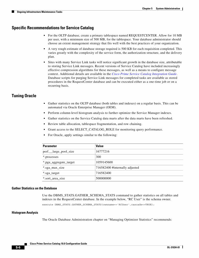
Chapter 5 System Administration Ongoing Infrastructure Maintenance Tasks
Specific Recommendations for Service Catalog
• For the OLTP database, create a primary tablespace named REQUESTCENTER. Allow for 10 MB per user, with a minimum size of 500 MB, for the tablespace. Your database administrator should choose an extent management strategy that fits well with the best practices of your organization.
• A very rough estimate of database storage required is 500 KB for each requisition completed. This varies greatly with the complexity of the service form, the authorization structure, and the delivery plan.
• Sites with many Service Link tasks will notice significant growth in the database size, attributable to storing Service Link messages. Recent versions of Service Catalog have included increasingly effective compression algorithms for these messages, as well as a means to configure message context. Additional details are available in the Cisco Prime Service Catalog Integration Guide. Database scripts for purging Service Link messages for completed tasks are available as stored procedures in the RequestCenter database and can be executed either as a one-time job or on a recurring basis.
Tuning Oracle
• Gather statistics on the OLTP database (both tables and indexes) on a regular basis. This can be automated via Oracle Enterprise Manager (OEM).
• Perform column-level histogram analysis to further optimize the Service Manager indexes.
• Gather statistics on the Service Catalog data marts after the data marts have been refreshed.
• Review table allocation, tablespace fragmentation, and row chaining.
• Grant access to the SELECT_CATALOG_ROLE for monitoring query performance.
• For Oracle, apply settings similar to the following:
Gather Statistics on the Database
Use the DBMS_STATS.GATHER_SCHEMA_STATS command to gather statistics on all tables and indexes in the RequestCenter database. In the example below, “RC User” is the schema owner.
execute DBMS_STATS.GATHER_SCHEMA_STATS(ownname=>'RCUser',cascade=>TRUE);
Histogram Analysis
The Oracle Database Administration chapter on “Managing Optimizer Statistics” recommends:
Parameter Value
perf.__large_pool_size 16777216
*.processes 300
*.pga_aggregate_target 1059145600
*.sga_max_size 716582400 #internally adjusted
*.sga_target 716582400
*.sort_area_size 500000000
5-6Cisco Prime Service Catalog 10.0 Configuration Guide
OL-31034-01

Chapter 5 System AdministrationOngoing Infrastructure Maintenance Tasks
• When gathering statistics on a table, DBMS_STATS gathers information about the data distribution of the columns within the table. The most basic information about the data distribution is the maximum value and minimum value of the column. However, this level of statistics may be insufficient for the optimizer's needs if the data within the column is skewed. For skewed data distributions, histograms can also be created as part of the column statistics to describe the data distribution of a given column.
• Histograms are specified using the METHOD_OPT argument of the DBMS_STATS gathering procedures. Oracle Corporation recommends setting the METHOD_OPT to FOR ALL COLUMNS SIZE AUTO. With this setting, Oracle automatically determines which columns require histograms and the number of buckets (size) of each histogram. You can also manually specify which columns should have histograms and the size of each histogram.
The tables for which it is critical to gather histogram-level statistics are:
• TxActivity
• TxProcess
• TxRequisition
• TxRequisitionEntry
• DirPerson
• DirOrganizationalUnit
• UIEntry
A sample DBMS_STATS command for collecting the statistics on each table would like look:
BEGIN DBMS_STATS.GATHER_TABLE_STATS (OWNNAME => 'RCUser', TABNAME => 'TXACTIVITY', METHOD_OPT => 'FOR ALL COLUMNS SIZE AUTO');END;
Tuning SQLServer
Enable snapshots with this command:
ALTER DATABASE <database name> SET READ_COMMITTED_SNAPSHOT ON
A SQLServer DBCC Reindex command is recommended, especially on volatile Service Catalog tables. The process should be regularly scheduled, typically weekly, at off hours.
The tables listed below are the most volatile and should be subject to DBCC Reindex.
5-7Cisco Prime Service Catalog 10.0 Configuration Guide
OL-31034-01

Chapter 5 System Administration Ongoing Infrastructure Maintenance Tasks
Sizing Cognos Database Components
Cognos maintains the definitions of all reports and queries in a database called the ContentStore. The Cognos KnowledgeBase includes entries on sizing and maintaining the ContentStore. Of particular interest are the formulas published for determining the size required for the ContentStore, based on estimated usage statistics.
A spreadsheet incorporating these formulas is available from the Cisco Technical Assistance Center (TAC). A sample is shown below.
TxActivity
TxActivityAssignment
TxAttribute
TxCheckList
TxChecklistEntry
TxComments
TxCondition
TxDictionaryHTMLBindings
TxDocument
TxEmailSent
TxEventTrigger
TxEventTriggerParam
TxIncident
TxInternalOptionList
TxInvocation
TxInvocationAttribute
TxJMSMessage
TxJoin
TxMultivalue
TxObjectDataHTML
TxObjectDictionaries
TxObjectRelation
TxPerformerSummary
TxProcess
TxRequisition
TxRequisitionEntry
TxRequisitionStep
TxRole
TxRule
TxSatisfaction
TxService
TxSubscription
TxTimer
Component # EstimatedSpace per Unit (KB) Total (KB)
Active Users 250
Concurrent Users executing reports (Temporary disk space requirements)
50 100,000 5,000,000
Saved Reports 1-10 pages (2 per user, 1-Public, 1 – MyFolder)
500 340 170,000
Saved Reports 10-100 pages (9 per user, 4-Public, 5 – MyFolder)
2250 440 990,000
Saved Views 1-100 rows (3 per user – all MyFolders)
750 250 187,500
Saved Views 100-1000 rows (8 per user – all MyFolders)
2000 350 700,000
Folders Public MyFolders (5 per user) 1,250 0
FrameMaker Models (provided by Cisco) 20,000
Empty Content Store 1 3,000 3,000
Active Schedules (50 Day + 125 Weekly) 175 30 5,250
Total 7,075,750
5-8Cisco Prime Service Catalog 10.0 Configuration Guide
OL-31034-01

Chapter 5 System AdministrationOngoing Infrastructure Maintenance Tasks
OLTP Database Tables
The transactional database consists of a set of relational tables that use a prefix naming convention. So, what exactly do these prefixes mean? The following table is provided as an aid to DBAs or others who need to maintain or tune a production database. The structure and contents of these tables is proprietary to Cisco, which reserves the right to freely change table names or structures from release to release.
Prefix Meaning Usage
Cnf Configuration Tables which contain internal configuration information used by Service Catalog; typically, these tables are small and their contents static in a production environment.
Co Portal Content Tables which contain Portal Manager Content and Page definitions.
Def Definition Tables which hold user definitions of user-configurable objects such as service forms, dictionaries, and checklists; table size varies with the size of the implementation, but is relatively stable in a production environment, typically changed only via usage of the Catalog Deployer.
Dir Directory Tables containing person and organizational information; table size for most is quite small (skills, projects, functional positions) and stable; those relating to persons vary greatly per organizational size.
JMS Java Message Service Internal Usage.
Mdr Meta-data Repository Tables containing meta-data for tables with a (user-defined) dynamic schema (for example. service items, standards, and portal).
Si Service Item Tables containing data for service items.
St Standards Tables containing data for standards.
Tx Transaction Tables which contain all transactions. Tables can be quite large and volatile.
Uc User Content Tables containing Portal Manager custom content.
UI User Interface Tables which define user-specific customizations for the user interface, such as Service Manager views, the default module that appears on login, and Service Link filters.
Xtr External Tables used by Service Link to manage external tasks; the definition tables (XtrDef) may be quite small, but the tables containing messages for external tasks are large and quick-growing.
XtrEUI External End User Integration
Tables used for Directory Integration definitions.
5-9Cisco Prime Service Catalog 10.0 Configuration Guide
OL-31034-01
Chapter 5 System Administration Performing Application Housekeeping
Performing Application Housekeeping
Historical Requisition Partitioning
Historical Requisition Partitioning feature migrates completed requisitions, namely, requisitions that have "Closed", "Canceled", "Delivery Canceled" or "Rejected" status, to historical transaction tables. The use of Historical Requisition Partitioning provides overall application performance improvement as a result of reducing the amount of data in the current transaction tables. The improvement can be seen in the filter and search of tasks, requisitions and external messages in the Service Manager, My Services and Service Link modules. ETL and request workflow processing will also benefit from the smaller population of data in the current transaction tables.
Historical Requisition Partitioning is controlled by the system setting "Enable Historical Requisitions Scheduler" in the Administration module. When it is enabled, requisitions that have been completed for more than 365 days are migrated by a background process to the historical transaction tables. The 365-day retention period is configurable and may be modified based on the specific needs of your organization. You may also execute the migration process of historical requisitions on an ad-hoc basis in the Administration > Utilities page when the scheduler is disabled.
As a result of the above changes, requisition views in both My Services and Service Manager are now separated into "Recent" and "Historical" views. Requisitions migrated to the historical transaction tables can be made accessible in the user interface by turning on the "Enable Historical Requisitions View" system setting. These requisitions are displayed on the "Historical" subtab on the My Services > Requisitions page, as well as the "Historical Requisitions" view in Service Manager. Tasks and external messages associated with the historical requisitions are currently not available for viewing in the user interface although the data are still stored within the Request Center database. The ability to access them online will be enabled in future releases and/or patches.
Preparing for Historical Requisition Partitioning
The first-time execution of the historical requisition migration will likely cover a large amount of data. To reduce the impact to application users, consider executing the process manually from the Administration module during one or multiple off-peak periods. To do so, navigate to Administration module and ensure that the "Enable Historical Requisitions Scheduler" setting is off. Then navigate to the "Run Processes" subtab under Utilities, enter the desired cut-off date and, optionally, the batch size and maximum number of requisitions to process. A larger batch size shortens the processing time but requires higher amount of temporary space or rollback segment in the database server. Setting the maximum number of requisitions or clicking the "Stop" button at any time allows you to limit the duration of the historical requisition migration process.
The processing rate and duration vary based on the average size of the requisitions. Before executing the migration process in your production environment, you should work with the database administrators and perform trial runs to estimate the time required for the first-time execution.
Considerations for Datamart
If you have the Reporting module, please note that historical transaction data are not extracted by the ETL process. Consider the following when configuring the historical requisition partitioning feature:
5-10Cisco Prime Service Catalog 10.0 Configuration Guide
OL-31034-01

Chapter 5 System AdministrationPerforming Application Housekeeping
• ETL process is normally scheduled to run on a frequent basis. Hence requisition data would have been captured into Datamart prior to their migration to the historical tables. To ensure there is no data loss in the Datamart, always set the historical requisition retention period to be greater than the frequency of the ETL process. For example, if ETL is set to run every 30 days, the historical requisition retention period should be set to 31 days or more.
• The process that migrates historical transaction data is automatically put on hold when it detects that the most recent ETL process timestamp is earlier than the cutoff date. For example, if the last ETL execution was on May 1st 12pm and the migration is going to select requisitions completed before May 1st 12:30pm, the migration process will exit immediately. This ensures that data are kept in the current transaction tables for extraction into Datamart before they get migrated.
• If your organization has the need to rebuild Datamart occasionally to capture backdated data (for example, making a dictionary or service reportable after the fact), the changes will not take effect on historical transactions by re-running the ETL process. In fact, the historical data will not be recoverable in the Datamart once they have been purged. To ensure such Datamart rebuild process is still possible, configure the data retention period to a duration that has provisions for backdated changes. In addition, the Datamart should no longer be emptied in a rebuild process for the reason above. Only the portion of data that are still available in the current transaction tables can be deleted and re-inserted into the Datamart during the re-execution of ETL.
Key Settings for Historical Requisition Processing
1. newscale.properties file (located in the RequestCenter.ear/config directory)
– reqArchival.poller.cron - This controls the frequency of the background process that migrates historical data. It uses the standard cron syntax and is scheduled to run every 30 minutes.
– reqArchival.process.maxRecords - This controls the maximum number of requisitions to be processed in each run. A higher number may be set if the process is intended to be run for a longer period of time during scheduled maintenance.
– reqArchival.cutOffDate.days - This controls the retention period of completed requisitions in the current transaction tables. By default, the retention period is set to 365 days.
– reqArchival.process.batchSize - This controls the number of historical requisitions included during each database commit. A larger batch size will shorten the processing time but will require higher amount of temp space or rollback segment in the database server.
2. support.properties file (located in the RequestCenter.ear/config directory)
– reqArchival.poller.enable - This controls whether the application instance can be used to run the historical requisition migration process. In a clustered Request Center environment, only one of the nodes will be used to execute the migration process at any time. One or more of the nodes may have this property set to "false" if the server is a less powerful machine or is meant for disaster recovery purpose.
Other settings in the above files should remain unchanged under normal circumstances.
5-11Cisco Prime Service Catalog 10.0 Configuration Guide
OL-31034-01
Chapter 5 System Administration Performing Application Housekeeping
Requisition Purge
Overview
Service Catalog provides a transaction purge feature to delete transactions older than a chosen date or that meet other user-specified criteria. This allows the application administrator to remove test requisitions before deleting test users and sample services. The purge scripts may also be used for housekeeping purposes to control the database size, for example, to delete older requisitions that no longer need to be retained. However the purge scripts are not optimized for mass data deletion and should be used with caution to avoid prolonged maintenance window.
Prerequisite software for the purge utility is a database client on the machine where the purge scripts are to be executed. For Oracle, “sqlplus” has to be installed and configured to connect to the RequestCenter database; for SQL Server, “osql” is required.
Preparations
Step 1 Make a backup of the RequestCenter database before executing the purge scripts.
Step 2 Stop the Request Center and Service Link services while the purge scripts are executed.
Step 3 Locate the utility in:
<APP_HOME>\schema\util\purge
Step 4 If the machine where <APP_HOME> resides has the prerequisite database client software, then you can execute the purge scripts from this machine. Otherwise, copy the entire purge folder to the machine where the RequestCenter database is located, or to another machine that has the prerequisite database client.
Step 5 Verify that the purge folder contains the following files:
• AddPurgeFilter.bat
• AddPurgeFilter.sh
• ClearAllPurgeFilter.bat
• ClearAllPurgeFilter.sh
• PurgeRequisitions.bat
• PurgeRequisitions.sh
Step 6 Execute the .bat files if you are on Windows operating system, or the .sh files if you are on UNIX or Linux operating system.
Caution If you have applied any Service Catalog service packs, repeat Steps 3 and 4 above, to ensure that you use the latest version of the purge scripts, as the scripts may be modified as part of the service packs.
Using the Scripts
To define and execute the requisition purge:
5-12Cisco Prime Service Catalog 10.0 Configuration Guide
OL-31034-01

Chapter 5 System AdministrationPerforming Application Housekeeping
Step 1 Clear purge filter criteria.
Step 2 Configure purge filter criteria.
Step 3 Perform a dry run for the requisition purge.
Step 4 Perform the actual requisition purge.
Clearing Purge Filter Criteria
This step is not required if the same filter criteria are always used for purging requisitions (for example, purge all cancelled requisitions). However, as a good practice, it is recommended that the criteria from the previous run are cleared first to avoid confusion.
Use the ClearAllPurgeFilter script to clear one or all filter criteria. If [Purge Filter Name] is not given, the script will remove all filter entries from the CnfPurgeFilter table in the RequestCenter database. Otherwise, the script removes only the specified [Purge Filter Name] if it exists in the CnfPurgeFilter table.
Oracle:
ClearAllPurgeFilter ORACLE [SID] [User] [Password] [Purge Filter Name (optional)]
SQL Server:
ClearAllPurgeFilter SQLSERVER [Server] [Database] [User] [Password] [Purge Filter Name (optional)]
Possible values for the optional [Purge Filter Name] are:
• CREATIONSTARTDATE
• CREATIONENDDATE
• CLOSEDSTARTDATE
• CLOSEDENDDATE
• REQUISITIONSTATUS
• REQUISITIONID
• REQUISITIONRANGE
• SERVICEID
• SERVICENAME
Adding Purge Filter Criteria
Use the AddPurgeFilter script to add one or more filter criteria. Requisitions will be deleted only if they meet all the purge criteria. The filter criteria are stored in the table CnfPurgeFilter in the RequestCenter database.
Use the command syntax below appropriate to your database type:
• [SID] is the ORACLE_SID for Oracle database
• [Server] is the SQL Server database server name
• [User] is “RCUser”
• [Password] is the password for “RCUser”
• Refer to the parameters table for possible values for [Purge Filter Name] and [Purge Filter Value]
5-13Cisco Prime Service Catalog 10.0 Configuration Guide
OL-31034-01
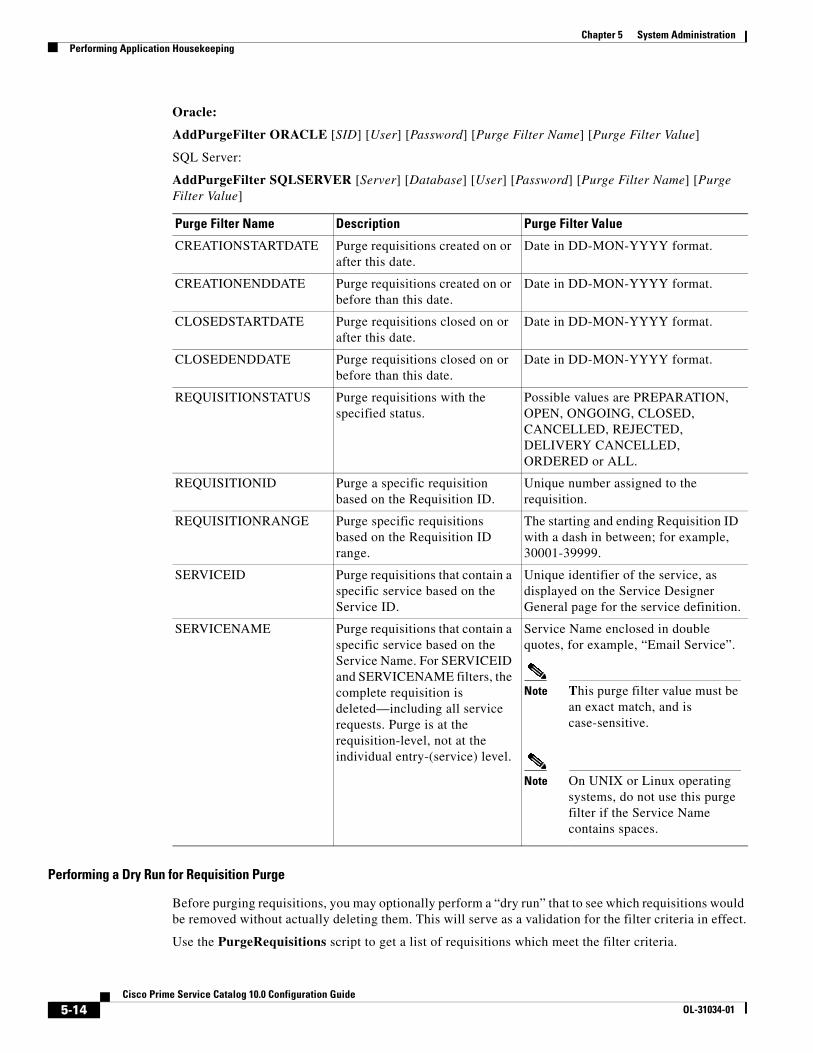
Chapter 5 System Administration Performing Application Housekeeping
Oracle:
AddPurgeFilter ORACLE [SID] [User] [Password] [Purge Filter Name] [Purge Filter Value]
SQL Server:
AddPurgeFilter SQLSERVER [Server] [Database] [User] [Password] [Purge Filter Name] [Purge Filter Value]
Performing a Dry Run for Requisition Purge
Before purging requisitions, you may optionally perform a “dry run” that to see which requisitions would be removed without actually deleting them. This will serve as a validation for the filter criteria in effect.
Use the PurgeRequisitions script to get a list of requisitions which meet the filter criteria.
Purge Filter Name Description Purge Filter Value
CREATIONSTARTDATE Purge requisitions created on or after this date.
Date in DD-MON-YYYY format.
CREATIONENDDATE Purge requisitions created on or before than this date.
Date in DD-MON-YYYY format.
CLOSEDSTARTDATE Purge requisitions closed on or after this date.
Date in DD-MON-YYYY format.
CLOSEDENDDATE Purge requisitions closed on or before than this date.
Date in DD-MON-YYYY format.
REQUISITIONSTATUS Purge requisitions with the specified status.
Possible values are PREPARATION, OPEN, ONGOING, CLOSED, CANCELLED, REJECTED, DELIVERY CANCELLED, ORDERED or ALL.
REQUISITIONID Purge a specific requisition based on the Requisition ID.
Unique number assigned to the requisition.
REQUISITIONRANGE Purge specific requisitions based on the Requisition ID range.
The starting and ending Requisition ID with a dash in between; for example, 30001-39999.
SERVICEID Purge requisitions that contain a specific service based on the Service ID.
Unique identifier of the service, as displayed on the Service Designer General page for the service definition.
SERVICENAME Purge requisitions that contain a specific service based on the Service Name. For SERVICEID and SERVICENAME filters, the complete requisition is deleted—including all service requests. Purge is at the requisition-level, not at the individual entry-(service) level.
Service Name enclosed in double quotes, for example, “Email Service”.
Note This purge filter value must be an exact match, and is case-sensitive.
Note On UNIX or Linux operating systems, do not use this purge filter if the Service Name contains spaces.
5-14Cisco Prime Service Catalog 10.0 Configuration Guide
OL-31034-01
Chapter 5 System AdministrationPerforming Application Housekeeping
Oracle:
PurgeRequisitions ORACLE [SID] [User] [Password] DRY_RUN [UserName]
SQL Server:
PurgeRequisitions SQLSERVER [Server] [Database] [User] [Password] DRY_RUN [UserName]
UserName is the Service Catalog login name of the person executing the script.
The list of requisitions found in a dry run is stored in the LogPurge table in the RequestCenter database. The log entries are appended to the table with a RunID incremented by 1 for every execution. You can review the requisitions to be purged by querying the LogPurge table entries with the highest RunID.
The LogPurge table can grow quickly over time, if you perform many dry runs and requisition purges. Therefore, it is recommended that you manually truncate the LogPurge table periodically to remove entries from previous runs.
You can repeat Steps 1 to 3 to revise the purge criteria. Once the purge filter criteria have been finalized, you can proceed with the actual requisition purge.
Performing the Requisition Purge
The requisition purge removes those requisitions that meet the purge filter criteria and all transactional data associated with those requisitions, including tasks and Service Link messages.
Results from the actual requisition purge are also appended to the LogPurge table in the RequestCenter database. To perform the actual requisition purge, use the same command PurgeRequisitions with the PURGE parameter as shown below.
Oracle:
PurgeRequisitions ORACLE [SID] [User] [Password] PURGE [UserName]
SQL Server:
PurgeRequisitions SQLSERVER [Server] [Database] [User] [Password] PURGE [UserName]
UserName is the Service Catalog login name of the person executing the script.
Workflow PurgeThe workflow purge utility removes temporary data from the database related to workflow processing. Those data are no longer used in the product and can be removed to reduce the database size. Executing the purge utility periodically could also provide overall performance improvement.
The workflow purge utility is provided in the form of a stored procedure in the RequestCenter database. The purge utility can require an hour or more to execute if you have a large database. Hence the purge should be done during system down time or a low activity time window. A practice run is recommended on a sandbox environment to establish how long the script will run for your database.
To track the start/end times for the purge, enable the setting for displaying print statements in the SQL tool before you execute the stored procedure.
5-15Cisco Prime Service Catalog 10.0 Configuration Guide
OL-31034-01

Chapter 5 System Administration Performing Application Housekeeping
Running the Utility on an Oracle Database
To run the utility on an Oracle database:
Step 1 Back up the RequestCenter database.
Step 2 Use a query tool appropriate for your database (for example, SQL*Plus) and connect to RequestCenter database as the RCUser.
Step 3 Execute the following commands:
• SET SERVEROUTPUT ON
• EXECUTE sp_PurgeWorkflowTables ([FromDate], [ToDate], [UserName]);
Dates must be in DD-MON-YYYY format. UserName is the Service Catalog login name of the person executing the script.
At the end of the execution, the total elapsed time should be displayed. Here is an example of the output:
Creation/Data population of TxReq_temp- SuccessfulTime taken for TxReq_Temp : .17 sCreation/Data population of TxReqEntry_temp- SuccessfulTime taken for TxReqEntry_Temp : .08 sCreation/Data population of TxSubscription_Temp - SuccessfulTime Taken for TxSubscritpion : 5.39 sCreation/Data population of TxProcess_Temp - SuccessfulCreation/Data population of TxJoin_Temp - SuccessfulTime Taken for TxJoin : .91 sCreation/Data population of TxCondition_Temp - SuccessfulTime Taken for TxCondition : 1.18 sCreation/Data population of TxActivity_Temp - SuccessfulCreation/Data population of TxEventTrigger_Temp - SuccessfulCreation/Data population of TxEventTriggerParam_Temp - SuccessfulTime Taken for TxEventTriggerParam : .33 s***Creation/Data population of TxEventTrigger - Successful******Creation/Data population of TxProcess - Successful***Creation/Data population of XtrChannelInfo_Temp - SuccessfulCreation/Data population of XtrChannelParameterSpec_Temp - Successful***Creation/Data population of XtrChannelParameterSpec - Successful***Elapsed time: 10.62 s
PL/SQL procedure successfully completed.
Running the Utility on an SQL Server Database
To run the utility on an SQL Server database:
Step 1 Back up the RequestCenter database.
Step 2 Use a query tool appropriate for your database (for example SQL Server Management Studio) and connect to RequestCenter database as the RCUser.
Step 3 Execute the following command:
• EXECUTE sp_PurgeWorkflowTables [FromDate], [ToDate], [UserName]
Dates must be in DD-MON-YYYY format. UserName is the Service Catalog login name of the person executing the script.
5-16Cisco Prime Service Catalog 10.0 Configuration Guide
OL-31034-01

Chapter 5 System AdministrationPerforming Application Housekeeping
At the end of the execution, the total elapsed time should be displayed. Here’s an example of the output:
(2258 row(s) affected)Creation/Data population of TxReq_Temp- SuccessfulTime taken for TxReq_Temp : 0 s(2639 row(s) affected)Creation/Data population of TxReq_Temp- SuccessfulTime taken for TxReqEntry_Temp : 0 s(56580 row(s) affected)(0 row(s) affected)(56580 row(s) affected)Creation/Data population of TxSubscription_Temp - SuccessfulTime taken for TxSubscription_Temp : 6 s(4551 row(s) affected)(2 row(s) affected)Creation/Data population of TxProcess_Temp - SuccessfulTime taken for TxProcess_Temp : 0 s(4154 row(s) affected)(0 row(s) affected)(4154 row(s) affected)Creation/Data population of TxJoin_Temp - SuccessfulTime taken for TxJoin_Temp : 1 s(9382 row(s) affected)(9382 row(s) affected)Creation/Data population of TxCondition_Temp - SuccessfulTime taken for TxCondition_Temp : 2 s(7017 row(s) affected)Creation/Data population of TxActivity_Temp - SuccessfulTime taken for TxActivity_Temp : 0 s(5528 row(s) affected)Creation/Data population of TxEventTrigger_Temp - SuccessfulTime taken for TxEventTrigger_Temp : 0 s(1202 row(s) affected)Creation/Data population of TxEventTriggerParam_Temp - SuccessfulTime taken for TxEventTriggerParam_Temp : 0 s(5528 row(s) affected)***Creation/Data population of TxEventTrigger - Successful***(1202 row(s) affected)***Creation/Data population of TxEventTriggerParam - Successful***(4553 row(s) affected)***Creation/Data population of TxProcess - Successful***(645 row(s) affected)Creation/Data population of XtrChannelInfo_Temp - SuccessfulTime taken for XtrChannelInfo_Temp : 0 s(8409 row(s) affected)(8409 row(s) affected)***Creation/Data population of XtrChannelParameterSpec - Successful***Elapsed time: 11 s
Service Link Messages PurgeThe Service Link Message Purge Utility removes nsXML messages from the database. Since these messages can be quite large (depending on the complexity of the service form and content type option used to configure the agent), removing the messages greatly reduces the database size required to hold Service Link-related data. External messages remain unchanged.
5-17Cisco Prime Service Catalog 10.0 Configuration Guide
OL-31034-01
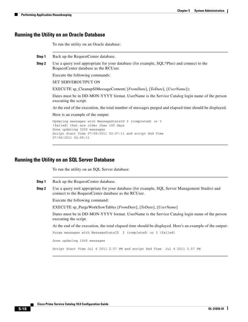
Chapter 5 System Administration Performing Application Housekeeping
Running the Utility on an Oracle Database
To run the utility on an Oracle database:
Step 1 Back up the RequestCenter database.
Step 2 Use a query tool appropriate for your database (for example, SQL*Plus) and connect to the RequestCenter database as the RCUser.
Execute the following commands:
SET SERVEROUTPUT ON
EXECUTE sp_CleanupSlMessageContent( [FromDate], [ToDate], [UserName]);
Dates must be in DD-MON-YYYY format. UserName is the Service Catalog login name of the person executing the script.
At the end of the execution, the total number of messages purged and elapsed time should be displayed.
Here is an example of the output:
Updating messages with MessageStateID 2 (completed) or 3 (failed) that are older than 100 days Done updating 3200 messages Script Start Time 07/06/2011 02:07:11 and script End Time 07/06/2011 02:09:11
Running the Utility on an SQL Server Database
To run the utility on an SQL Server database:
Step 1 Back up the RequestCenter database.
Step 2 Use a query tool appropriate for your database (for example, SQL Server Management Studio) and connect to the RequestCenter database as the RCUser.
Execute the following command:
EXECUTE sp_PurgeWorkflowTables [FromDate], [ToDate], [UserName]
Dates must be in DD-MON-YYYY format. UserName is the Service Catalog login name of the person executing the script.
At the end of the execution, the total elapsed time should be displayed. Here's an example of the output:
Purge messages with MessageStateID 2 (completed) or 3 (failed)
Done updating 1500 messages
Script Start Time Jul 6 2011 2.57 PM and script End Time Jul 6 2011 3.57 PM
5-18Cisco Prime Service Catalog 10.0 Configuration Guide
OL-31034-01
Chapter 5 System AdministrationManaging the Application
Undelivered Emails
Email notifications that failed to be delivered are kept in the application for review or retry. To do so, navigate to the Administration module, and locate the "Undelivered Emails" tab under Utilities. There you may delete the messages if they have invalid information, or re-send them if they failed to be delivered due to temporary SMTP outage.
As a good practice, administrator should review this application page on a regular basis to identify messages that need to be re-sent. Email notification process may slow down substantially if there is a large number of messages left in the backlog.
Managing the ApplicationThis section provides information about the following J2EE application components of Service Catalog:
• Request Center – This component comprises the heart of the application—all screens that the user sees, all validation, help screens, and APIs in Service Catalog.
• Service Link (IS or ISEE) – This is the Integration Server, which uses agents and adapters to allow integration with a variety of third-party systems.
In this section you will learn how to deploy the application, about key configuration files, and managing WebSphere, WebLogic, and JBoss. Additionally, there is information about working with data sources and creating “backing tables” for external data dictionaries, about cached data, application security, applying patches, and multicast settings.
The Basics
Deploying the Application
The .war file for Request Center is deployed into the file system. The exact location of these files will vary, depending on application server. For example, in a WebSphere implementation these files are generally found under a path that looks like:
/apps/WebSphere/AppServer/profiles/newScale/installedApps/Cell/RequestCenter.war
The Service Link application is provided as a .war file, ISEE.war (Integration Server Enterprise Edition.) The WebSphere application server automatically “wraps” an .ear around a standalone .war file.
Restarting the Server
Use the Server Console for your application server or command-line scripts as appropriate to restart the server. Make sure to make a script available to the Administrator in the development environment.
Key Configuration FilesThe following are important files that you may need to see for details on your deployment. Unless specifically stated in this guide or instructed by the Cisco Technical Assistance Center (TAC), all properties files and similar configuration files should be considered read-only. After making changes to any of these property files, you must restart the services.
5-19Cisco Prime Service Catalog 10.0 Configuration Guide
OL-31034-01
Chapter 5 System Administration Managing the Application
newscale.properties
This file is created by the installer during the install or upgrade process and any time the installer is run. The file produced by the installer is contained in the “RequestCenter.war\WEB-INF\classes\config” folder. As such, the file is redeployed any time the ear is redeployed. The Service Catalog administrator should preserve the data contained in the file, but should not simply restore a copy of the file since the installer may have added new information for the new version. Entries in newscale.properties include:
• udk.datasource.jndi – JNDI name for your RC database
• udk.datamart.jndi – JNDI name for your data mart database
• All registered EJBs
• ObjectCache.Application.URL – URL reference back to the application in the emails sent out
• ObjectCache.email.host – SMTP host for relaying mail
• Container.Datasource – JNDI name for the RequestCenter database
• Scheduler.EscalationManagerSchedule – Schedule for evaluating escalations
rcjms.properties
This file is also located in the “RequestCenter.war\WEB-INF\classes\config” folder. It contains the JMS settings for application internal communications. Please ensure that the queue names match the ones on the application server.
integrationserver.properties
This file is located in the “ISEE.war\WEB-INF\classes\config” folder. It contains the key properties of the integration server (Service Link).
Managing LogsService Catalog maintains log files on the application server to track application activities, both expected and unexpected. Logs are managed using a log4j-based framework, an open source (Apache) logging mechanism. By default, logs are configured as “rolling appenders”, with a new log file opened every day. Location of the log files varies according to the application server type, as does the ability to adjust log file contents and configuration.
Recommendations:
• Rotate logs on a daily basis (this is the default behavior)
• Keep one month of logs “online”
• Back up or delete logs that are older than a company-specified retention period
Service Catalog does not require log files to be maintained. They are useful primarily as troubleshooting tools in case an error arises.
We recommend against changing the format of the default log files because that is the format the Cisco Technical Assistance Center (TAC) expects. Rather, customers can create their own appenders that suit their needs.
In addition to the system-wide log files, Service Link is configured to have a separate log file for each adapter type. These logs, too, are managed by log4j. By default, Service Link logging is enabled. The adapter-specific log files, written to the ServiceLink\logs directory, are shown below.
5-20Cisco Prime Service Catalog 10.0 Configuration Guide
OL-31034-01
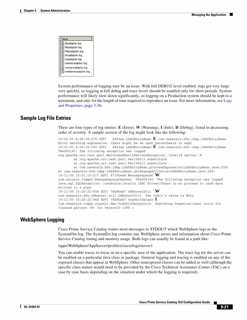
Chapter 5 System AdministrationManaging the Application
System performance of logging may be an issue. With full DEBUG level enabled, logs get very large very quickly, so logging at full debug and trace levels should be enabled only for short periods. System performance will likely slow down significantly, so logging on a Production system should be kept to a minimum, and only for the length of time required to reproduce an issue. For more information, see Logs and Properties, page 3-26.
Sample Log File Entries
There are four types of log entries: E (Error), W (Warning), I (Info), D (Debug), listed in decreasing order of severity. A sample section of the log might look like the following:
[8/22/05 8:58:39:279 CDT] 4643aa LDAPEntryBean E com.newscale.bfw.ldap.LDAPEntryBean Error matching expression, there might be an open parenthesis in expr [8/22/05 8:58:39:290 CDT] 4643aa LDAPEntryBean E com.newscale.bfw.ldap.LDAPEntryBean TRAS0014I: The following exception was logged org.apache.oro.text.perl.MalformedPerl5PatternException: Invalid option: N at org.apache.oro.text.perl.Perl5Util.substitute at org.apache.oro.text.perl.Perl5Util.substitute at com.newscale.bfw.ldap.LDAPEntryBean.processExpression(LDAPEntryBean.java:328) at com.newscale.bfw.ldap.LDAPEntryBean.getRegexpAttrValue(LDAPEntryBean.java:296) [9/11/05 15:01:10:217 EST] 4715bea8 MessagequeueC W com.celosis.logger.MessagequeueChannel TRAS0014I: The following exception was logged java.sql.SQLException: [newScale][Oracle JDBC Driver]There is no process to read data written to a pipe.[9/11/05 10:26:22:934 EST] 76b9beb7 UdKernelUtil W com.newscale.bfw.udkernel.util.UdKernelUtil The Cubic's value is NULL[9/11/05 10:26:22:944 EST] 76b9beb7 OrgUnitDataso I com.newscale.comps.orgunit.dao.OrgUnitDatasource Searching Organizational units for cleaned pattern <%> for PersonID <298 >
WebSphere Logging
Cisco Prime Service Catalog routes most messages to STDOUT which WebSphere logs to the SystemOut.log. The SystemErr.log contains any WebSphere errors and information about Cisco Prime Service Catalog timing and memory usage. Both logs can usually be found at a path like:
/apps/WebSphere/AppServer/profiles/cisco/logs/server1
You can enable traces to focus in on a specific area of the application. The trace log for the server can be enabled on a particular Java class or package. General logging and tracing is enabled on any of the exposed classes that appear in WebSphere. Other nonexposed classes can be added as well (although the specific class names would need to be provided by the Cisco Technical Assistance Center (TAC) on a case by case basis depending on the situation under which the logging is required).
5-21Cisco Prime Service Catalog 10.0 Configuration Guide
OL-31034-01

Chapter 5 System Administration Managing the Application
Runtime logging is an option which can be chosen through the WebSphere admin console GUI. Runtime logging allows logging and tracing to be enabled for the selected classes without restarting or rebooting the servers or applications.
All log files and locations are typically defined in the log4j.xml file. However, WebSphere has additional control over this as well. For almost any logging in WebSphere, the SystemOut.log file and any other log files in the directory it is located may be referred to and required for troubleshooting. In some cases, there may be adapter log files as well. These will typically be generated wherever the SystemOut.log file is generated for the Service Link server (if running on a cluster). Each node in a cluster will have its own SystemOut.log and related log files, so they may be needed for troubleshooting as required.
The log file properties with respect to trace parameters and locations are controlled by settings in the WebSphere admin console, and / or the log4j.xml associated with the WebSphere server. Enabling logging is fairly intuitive, and is something the WebSphere admin can do.
WebLogic Logging
In WebLogic, Cisco Prime Service Catalog routes messages according to the WebLogic logging configuration. By default, all logging goes to the WebLogic server log, which is usually found in a path similar to the following:
/apps/bea/user_projects/domains/cisco/servers/nsServer/logs/nsServer.log
The default log level is set to INFO, and is adjustable via the WLS Console.
JBoss Logging
The JBoss logs are located under “<JBOSS_DIR>/standalone/log” folder. The logging.properties file that determines logging behavior is located under the “<JBOSS_DIR>\standalone\configuration” folder. Log4j.xml is no longer used for controlling application logging.
Data SourcesAll modules depend on J2EE data sources, defined via JNDI (Java Naming and Directory Interface). These data sources must point to the correct database and have the appropriate login information configured.
Additional JNDI data sources are required if:
• External dictionaries are used.
• Customer-specific data sources are accessed by data retrieval rules or by option lists in a service definition that are based on a SQL statement or a relational database table.
Accessing external data sources on a type of database different than Service Catalog (for example, a SQLServer data source accessed from an instance of Service Catalog running on Oracle, or a Sybase data source accessed from any instance of Service Catalog) is not supported in a service form. Procedures for configuring data sources are detailed in the Cisco Prime Service Catalog Installation Guide, and are specific to the application server.
When you add data sources, you should use the Cisco drivers if possible.
5-22Cisco Prime Service Catalog 10.0 Configuration Guide
OL-31034-01

Chapter 5 System AdministrationManaging the Application
Creating “Backing Tables” for External DictionariesExternal dictionaries within the Service Catalog need to be “backed” by physical tables in the database. You cannot have read-only external dictionaries. All external dictionaries are read-write. Only the application should write to External Dictionaries.
For the application to relate External Dictionaries to the Requisition, a numeric column needs to be available that can be used as the foreign key. This is typically named RequisitionEntryID.
Sample SQL Listing to Create a Backing Table
This code creates a sequence that generates unique ids for each row. Creating an index on the RequisitionEntryID column greatly optimizes Service Manager performance.
The backing tables for external dictionaries are not transported by Catalog Deployer across environments. Only the dictionary definition can be deployed, as a component of a service.create sequence X_SEQ;
create table ( X_ID INT CONSTRAINT PK_X primary key, REQUISITION_ENTRY_ID INT, REQUESTORLANID VARCHAR2 (10), REQUESTORNAME VARCHAR2 (50), FUNDINGSOURCECODE VARCHAR2 (15), DATENEEDED DATE, REASONFORCHANGE VARCHAR2 (50), PROJECTNAME VARCHAR2 (50), TOPINITIATIVE VARCHAR2 (5));
create or replace trigger X_it before insert on X for each rowdeclare seq_val number;begin select X_seq.nextval into seq_val from dual; :new.X_ID := seq_val;end;
Applying Maintenance Releases and PatchesDetailed information about applying a maintenance release can be found in the Release Notes that accompany the release, or the readme file in the case of patches.
Some patches may simply require you to add or replace content in the currently installed deployment environment. In this case, the instructions in the readme would list, step by step, the procedures to follow and what software needs to be replaced.
Maintenance release and certain patches may require a complete upgrade/reinstall of the Service Catalog deployed environment. In this case, please ensure that you preserve any customizations and reapply them after the upgrade/reinstall.
Configuring Service Export via SSL or NTLMThe Service Export feature in Service Designer establishes a connection to Service Catalog, retrieves the exported XML, stores it in a file, and returns a link to the user.
5-23Cisco Prime Service Catalog 10.0 Configuration Guide
OL-31034-01

Chapter 5 System Administration Managing the Application
If the application is SSL-enabled, then the user will encounter a problem when trying to export a service as an XML document. The connection to the application needs to authenticate to the server, and the Service Catalog needs an SSL certificate.
To enable the “export service” feature when Service Catalog is SSL-enabled:
Step 1 Export the trusted root CA certificate used by the Service Catalog web server, in Base 64 Encoding format, into a file. The file will most likely have an “.arm” or “.cert” extension. This is a simple text file that can be opened in any text editor.
Step 2 Find the CA certs keystore that comes with the Java installation on your application server. The CA certs keystore for your Java installation is a file named cacerts.
• For JBoss, cacerts is located in <JAVA_HOME>\jre\lib\security.
• For WebSphere, cacerts is located in <WAS_HOME>/java/jre/lib/security.
Step 3 Import the trusted root CA certificate of the Request Center web server into the Java’s cacerts keystore. You can use either the Java keytool utility, or the IBM ikeyman utility if you are on a WebSphere environment.
• The keytool.exe program can be found in the <JAVA_HOME>/bin directory. For WebSphere, the Java keytool.exe program is located in the <WAS_HOME>/java/jre/bin directory.
The following example provides the command line syntax for the Java keytool utility, which will import the root CA certificate into cacerts:
keytool.exe -import -trustcacerts -alias RC –file <root_cert_file> -keystore C:\jdk1.6.0_12\jre\lib\security\cacerts
where <root_cert_file> is the full pathname of the file that contains the root CA certificate of the Service Catalog web server which you exported in step 1.
The keytool program will prompt you for a keystore password. For a new installation of Java, the default keystore password for the “cacerts” file is “changeit”. Enter changeit, or another value if you have already changed the password since you installed Java on this machine.
If the question “Trust this certificate?” appears, enter “y”.
Restart the application server instance, in order for the changes to take effect. Restart the whole instance of JBoss, WebSphere or WebLogic in this machine, and not just an individual server or application.
Cisco Prime Service Catalog Cached Data
Site Configuration Settings
Most site configuration settings are cached in the J2EE system for faster access. To reload any settings that are used by the J2EE application, change any option on the Settings page of the Administration module and click Update. This invalidates the cache and reloads the settings from that page.
5-24Cisco Prime Service Catalog 10.0 Configuration Guide
OL-31034-01

Chapter 5 System AdministrationManaging the Application
Business Engine Caching
Cisco Prime Service Catalog includes a proprietary work flow management system, sometimes referred to as the “Business Engine”. The actions of the Business Engine—managing the delivery plan—are largely transparent to application users, since they happen “behind the scenes”, that is, on the application server. However, a user interface is provided for system administrators to view and possibly adjust Business Engine operation.
Users with the Site Administrator system role can access the Business Engine console via the URL http://<serverName:portNumber>/RequestCenter/businessengine/index.jsp. There you can:
• View the Business Engine configuration
• Delete the Object Cache
• Force a run of the Escalation Manager
• View the transaction cache log
Other caching mechanisms are also in place within the application. The cached values are refreshed automatically as and when changes are made to the application data.
Cisco Prime Service Catalog Data Security
Database Security
User passwords are usually not stored in the database if external authentication via SSO is used. When they are, they are a one-way AES 128-bit hash. Passwords stored in configuration files or in the database are encrypted using a Public/Private key encryption. No additional encryption is applied to the data.
Configuration Files
Database passwords in configuration files are encrypted. When Service Link is configured, the J2EE container password is not encrypted and is stored as plain text in several configuration files.
URLs
URLs are not encoded; data-level security verifies authorization for each screen.
5-25Cisco Prime Service Catalog 10.0 Configuration Guide
OL-31034-01
Chapter 5 System Administration Managing the Application
Application Security
Setting up Secure LDAP
• Retrieve SSL certificates from the LDAP server.
• Ensure LDAP server supports SLDAP connectivity (typically on port 636).
Service Catalog maintains a password-protected key-store that can store many certificates.
SSL
It is recommended that the web server, or the content switch in front of the web server, run SSL, especially in Extranet-supported environments.
Web Server to Application Server communication does not usually need to be encrypted.
Removal of CGI support in Advanced Reporting
Several tools scan applications to ensure that no CGI-based submits (GET Form submissions) exist in the application.
Cross-Site Scripting
Cisco is focused on the security and safety of your data and is well aware of the threats presented by XSS (Cross-site scripting) attacks.
Service Catalog uses a standard J2EE input-filter-config.xml file to check that URLs do not contain any of the following characters: < > " ' ( ) & ;
This file is located in: RequestCenter.war\WEB-INF\config\.
Form Data Security
For installations that are on release 9.3.2 and above, there are a number of service design features that can be used to protect service requests from the “man-in-the-middle” attack. To thwart malicious attempts to intercept form data that are governed by form rules and default value settings, server-side rules and certain edit controls can be used to override or validate data being sent from the browser clients. More information about this can be found in the Cisco Prime Service Catalog Designer Guide.
ReportingThe Reporting modules require scripts that maintain the Service Catalog data mart and produce the standard reports and KPIs available to users.
Reporting Batch Programs
Service Catalog Extract-Transform-Load (ETL) scripts generated from the Cognos DataManager ETL tool control the population of the database which supports running prebuilt reports provided by Service Catalog and all nonform based data in the data mart.
Additional command files complete the generation of the framework used by Cognos QueryStudio and Report Studio (Ad-Hoc Reports and Report Designer) to permit ad-hoc reporting on the Service Catalog data mart.
5-26Cisco Prime Service Catalog 10.0 Configuration Guide
OL-31034-01

Chapter 5 System AdministrationManaging the Application
These scripts share the same invocation and logging framework. They are available as Windows .cmd files that reside and run on the Cognos server. They can be scheduled to run via any enterprise scheduler. These scripts log their activities in the <ReportingInstalledDirectory>\logs directory of the Cognos server.
The following script is required to support standard reports and Key Performance Indicators (KPIs).
The following programs are required to support the data marts.
Form-Data Extraction Script
Dictionaries and services designated as reportable are populated in the data mart by a Java program. The program activities are logged in the current log file on the application server.
This program is run via the internal scheduler. Schedule settings can be specified as part of the installation or modified by editing the newscale.properties file. The following properties configure the scheduler. We recommend running the ETL (and other processes) daily. The data mart will not be usable when the job is running. The ETL process is run with transaction logging. It may be advisable to increase the transaction size (FDR_ETL_RECORDS_PER_BATCH).
#Enable ETL Process: 0 or 1 (1=Yes, 0=No)ENABLE_FDR_ETL_PROCESS=0
# FDR_ETL_TRIGGER : 1 for hourly, 2 for daily, 3 for minutes FDR_ETL_TRIGGER=1
#Frequency HourlyFDR_ETL_TRIGGER_FREQUENCY_HOURLY=5
#Daily Time HH:MM (22:30 for 10:30 PM)FDR_ETL_TRIGGER_FREQUENCY_DAILY=22:30
#Frequency in minutesFDR_ETL_TRIGGER_FREQUENCY_MINUTES=1
Program Description/Usage
update_datamart_std.cmd Populates database tables which support the prebuilt reports according to ETL rules specified in Data Manager. This is a complete rebuild of the database contents, rather than an incremental refresh. Produces a log file in <cognos.root>\c8\datamanager\log.
Program Description/Usage
update_datamart.cmd Populates the data mart fact and dimension tables using rules specified in Data Manager, as well as the Demand Center data mart. This is an incremental refresh of all static dimensional and fact data. It produces a log file in <cognos.root>\c8\datamanager\log.
create_model.cmd Creates a Cognos FrameworkManager model that includes dynamically defined reportable objects (dictionaries and services) as well as standard facts and dimensions. The model is rebuilt by merging a statically defined model (the standard facts and dimensions used in the data marts) with dynamically generated metadata describing reportable services and dictionaries.
publish_fdr_pkg.cmd Publishes the FrameworkManager model to the Cognos BI Server, via the Cognos ScriptPlayer utility. Must be run as part of the Service Catalog data mart refresh, following the program that creates the model (create_model.cmd).
5-27Cisco Prime Service Catalog 10.0 Configuration Guide
OL-31034-01

Chapter 5 System Administration Managing the Application
#Number of records per batch insertionFDR_ETL_RECORDS_PER_BATCH=500
Escalation ManagerThe Escalation Manager is responsible for monitoring if/when a task exceeds its Operating Level Agreement (OLA). If the OLA is exceeded, and escalations have been configured, the Escalation Manager sends the appropriate notifications after the designated amount of time has elapsed since the task became overdue.
The Escalation Manager is run via the internal scheduler. Schedule settings can be adjusted by editing the newscale.properties file. By default the Escalation Manager is set to run during business hours Monday through Friday.
A schedule setting is essentially a cron expression, which describes the desired schedule in the format “Seconds Minutes Hours Day-of-Month Month Day-of-Week”. For example, the expression “0 0 12 ? * WED” means “every Wednesday at 12:00 pm”.
Service ManagerService Manager is the module used by task performers and to fulfill service requests.
Service Manager allows users to search for tasks or requisitions of interest by specifying a set of conditions to be matched, via the Filter and Search pop-up window. By default, these conditions do not support a “contains” operator, for example, the ability to find all task whose name contains a specified string.
This default behavior optimizes performance by increasing the probability that indexed queries can be run against the database. The functionality of performing “contains” queries can be supported; however, administrators should be careful in making this configuration change, as response time may not be optimal, especially with a large transactional database. Reverting back and forth is not recommended as it will impact Service Manager Custom Views.
To allow Service Manager users to specify “Contains” queries, edit the newscale.properties file, to add the following property setting:
# Service Manager will use this flag to control Contains Query in Datatable Filter and Search
ContainsQueryInFnS=true
As with all changes the properties files, the services must be stopped and restarted for this change to take effect.
Service Catalog InstallationInstallation settings are recorded in the RequestCenter/etc folder. Preserve that folder so that installation settings are “remembered” for future invocations of the Service Catalog Installer.
The settings are available in the file setup_options.txt. A sample is shown below.
5-28Cisco Prime Service Catalog 10.0 Configuration Guide
OL-31034-01
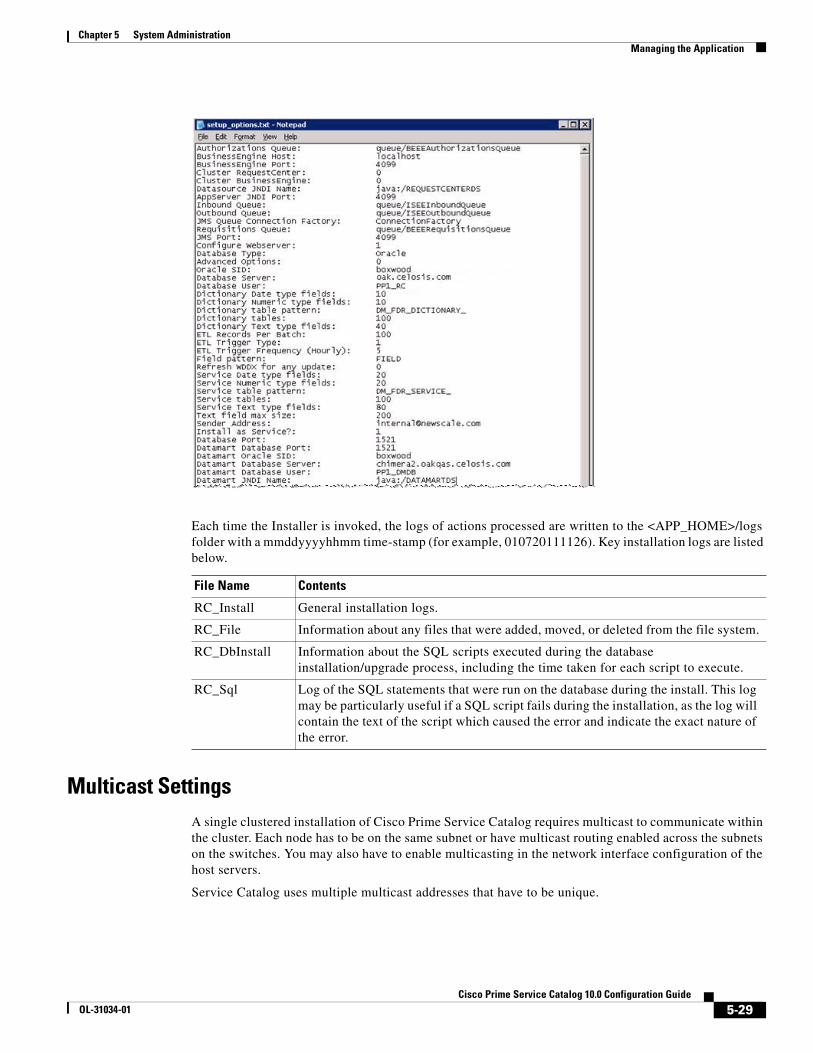
Chapter 5 System AdministrationManaging the Application
Each time the Installer is invoked, the logs of actions processed are written to the <APP_HOME>/logs folder with a mmddyyyyhhmm time-stamp (for example, 010720111126). Key installation logs are listed below.
Multicast SettingsA single clustered installation of Cisco Prime Service Catalog requires multicast to communicate within the cluster. Each node has to be on the same subnet or have multicast routing enabled across the subnets on the switches. You may also have to enable multicasting in the network interface configuration of the host servers.
Service Catalog uses multiple multicast addresses that have to be unique.
File Name Contents
RC_Install General installation logs.
RC_File Information about any files that were added, moved, or deleted from the file system.
RC_DbInstall Information about the SQL scripts executed during the database installation/upgrade process, including the time taken for each script to execute.
RC_Sql Log of the SQL statements that were run on the database during the install. This log may be particularly useful if a SQL script fails during the installation, as the log will contain the text of the script which caused the error and indicate the exact nature of the error.
5-29Cisco Prime Service Catalog 10.0 Configuration Guide
OL-31034-01

Chapter 5 System Administration Managing Integrations
Testing Multicast Connectivity
Test 1 – Can Node1 talk to Node2?
• Choose a valid multicast address and port that are not in use.
• On Node2: java -classpath .:./javagroups-all.jar org.javagroups.tests.McastReceiverTest -mcast_addr 224.10.10.10 -port 5555.
• On Node1: java -classpath .:./javagroups-all.jar org.javagroups.tests.McastSenderTest -mcast_addr 224.10.10.10 -port 5555.
• On Node1 you see a prompt “>”.
• Type in some text and hit [Return].
• Your text appears on Node2.
Test 2 – Can Node2 talk to Node1?
Repeat Test1 with Node2 as the Sender and Node1 as Receiver.
Managing IntegrationsThe complete reference of Service Catalog integration points is available in the Cisco Prime Service Catalog Integration Guide. This section provides an overview of the key integration strategies that the system administrator may pursue when configuring the Service Catalog application.
Integration TypesThe following types of integrations are supported:
Data-level Integration using Directory Integration
Synchronization of data between Service Catalog and an LDAP directory.
For example: Organizational Structure, Exchange Calendar Info.
Application-level Integration using Single Sign-On
Single Sign-On allows users to bypass the login screen and access Service Catalog directly from a portal or other application.
Form-level Integration using Interactive Service Forms (ISF) and Active Form Rules
JavaScript functions interact with third-party systems to collect, validate, or distribute form information and to adjust the appearance or behavior of the form dynamically.
For example: Cost Code Validation, Auto-Population of Fields.
Task-level Integration using Service Link
Service Link provides asynchronous messaging using HTTP, file, database, MQ and JMS adapters. External tasks trigger Service Link agents to issue a command to another system and expect a response.
5-30Cisco Prime Service Catalog 10.0 Configuration Guide
OL-31034-01
Chapter 5 System AdministrationManaging Integrations
For example: Open a Help Desk Ticket, Update an Asset, Order Equipment.
Requisition-level Integration using Web Services RAPI
A third-party application initiates an action within Cisco Prime Service Catalog using Requisition API (RAPI).
For example: Canceling a pay check in a financial system causes Service Catalog to initiate and manage an Off-Boarding Process to disable accounts and reclaim assets.
Directory IntegrationThe system allows for multiple LDAP directory integrations. A group of two or more LDAP sources becomes one LDAP system through referrals. For detailed information on configuring directory integrations, see the Cisco Prime Service Catalog Integration Guide.
Directory Integration allows integration architects to connect Service Catalog to an LDAP data source and map attributes in that data source to corresponding fields in the Person profile. The integration allows designers to designate which events should trigger an LDAP lookup, and whether that lookup should also cause a refresh of the Person profile in Service Catalog. Events that can trigger an LDAP lookup include:
• Authentication after login, either via the Service Catalog screen or Single Sign-On
• Person Search for Order On Behalf
• Person Search for form data in a Person-type field
• Lookup of Person information for the managers of a person previously chosen via Order on Behalf or Person Search
In addition to these preconfigured events and behavior, Directory Integration provides an API to allow programmers to implement custom directory interfaces to add new search capabilities or refine the search logic.
Directory Mappings
Directory data can be mapped to elements of a Person's profile including
• Basic and extended person attributes, including location and contact information
• One or more organizations
• One or more groups
• One or more roles
Four types of mappings are available:
• Simple mapping. A 1-to-1 mapping between a directory attribute and a Person field.
• Composite mapping. Two or more directory attributes are used to derive the value of a Person field.
• Expression mapping. A regular expression involving one or more directory attributes is used to conditionally derive the value of a Person field.
• Mapping via Java class, using the Directory Integration API. A Java plug-in derives the value of the Person field based on directory attributes available in the current directory data source for the current person.
If the Locale and Time Zone are not mapped, Service Catalog uses the server default.
5-31Cisco Prime Service Catalog 10.0 Configuration Guide
OL-31034-01

Chapter 5 System Administration Managing Integrations
If any optional fields are not mapped, any value previously populated in the Person profile will remain unchanged.
Custom Mappings
Custom mappings can be created via pattern-matching language (regular expressions), which is described in the Cisco Prime Service Catalog Integration Guide, and via a custom plug-in class based on an interface provided in the Directory Integration API.
Any such mappings should be documented in the LDAP Integration document for each implementation. Any Java classes required for the mapping are treated as customizations if/when a Service Catalog instance is migrated or upgraded.
Custom Code
Using the interfaces provided by the Directory Integration API, custom Java classes can replace or supplement the preconfigured behavior offered by the directory integration events. Any such classes are treated as customizations when/if an instance is migrated or upgraded.
Further, if the custom classes require supporting JAR files, these must be installed on the application server and treated as customizations. Installation procedures differ for each application server.
Single Sign-OnSingle Sign-On functionality is provided as part of Directory Integration.
Single Sign-On Troubleshooting
If you experience any problems with Single Sign-On, begin troubleshooting by checking the following items:
• Review any related changes to your environment such as LDAP or Junction/SiteMinder agent configurations.
• Can you still access Service Catalog via the Administrative override?
• Restart the Request Center service.
Single Sign-On: Configuring NTLM
Many environments use Windows authentication. IIS supports Integrated Windows Authentication (IWA) and passes the DOMAIN\UserName of the user who is logged in as a parameter.
Requirements
• Restart the IIS Admin Service (in Windows Services) after enabling IWA
• Valid domain accounts while accessing Service Catalog
• Configure SSO to strip DOMAIN information
5-32Cisco Prime Service Catalog 10.0 Configuration Guide
OL-31034-01

Chapter 5 System AdministrationIncluding Custom Content during Installation
Interactive Service Forms (ISF)ISF is a JavaScript API that integrates with Cisco Prime Service Catalog service forms. ISF allows the forms to dynamically alter their contents or behavior based on the current context, including user credentials; data previously entered on the form; or the life cycle of the displayed requisition. For more information on ISF, see the Cisco Prime Service Catalog Designer Guide.
ISF supports the use of JavaScript libraries, stored on the application or web server, to supplement JavaScript code stored in the Service Catalog repository. If such libraries are used, they are treated as customizations when upgrading or migrating a Service Catalog site.
Active Form RulesThe data retrieval rules available within active form components allow the application to retrieve data from external relational databases or from the application database, for use in service forms. Such data can be used to prefill form fields with default values; to produce drop-down lists; and to provide dynamically populated drill downs to detailed information. User data entry could also be validated against the external data.
For a rule to access an external database, a corresponding JEE datasource must be created. Instructions on creating the datasource are given in the Cisco Prime Service Catalog Installation Guide. Any such datasources are treated as customizations when upgrading or migrating the Service Catalog site.
Service LinkService Link, also known as the Integration Server, or ISEE (Integration Server Enterprise Edition), allows Service Catalog to send synchronous or asynchronous requests to other systems via XML messages.
Tasks that are configured in Service Designer as “external” are handled by Service Link.
Service Link uses JMS queues as an underlying technology, so disruption to JMS configuration may disrupt Service Link operation. Most Service Link troubleshooting can be done through the Service Link module which provides the ability to drill-down to individual messages sent or received and the tasks responsible for sending or receiving those messages.
Including Custom Content during Installation
OverviewThis section provides information about configuring your system for a customized installation of Service Catalog, and for ensuring that custom content is not deleted or overridden during subsequent installations or upgrades.
For more details on the Service Catalog installation wizard, see the Cisco Prime Service Catalog Installation Guide.
5-33Cisco Prime Service Catalog 10.0 Configuration Guide
OL-31034-01
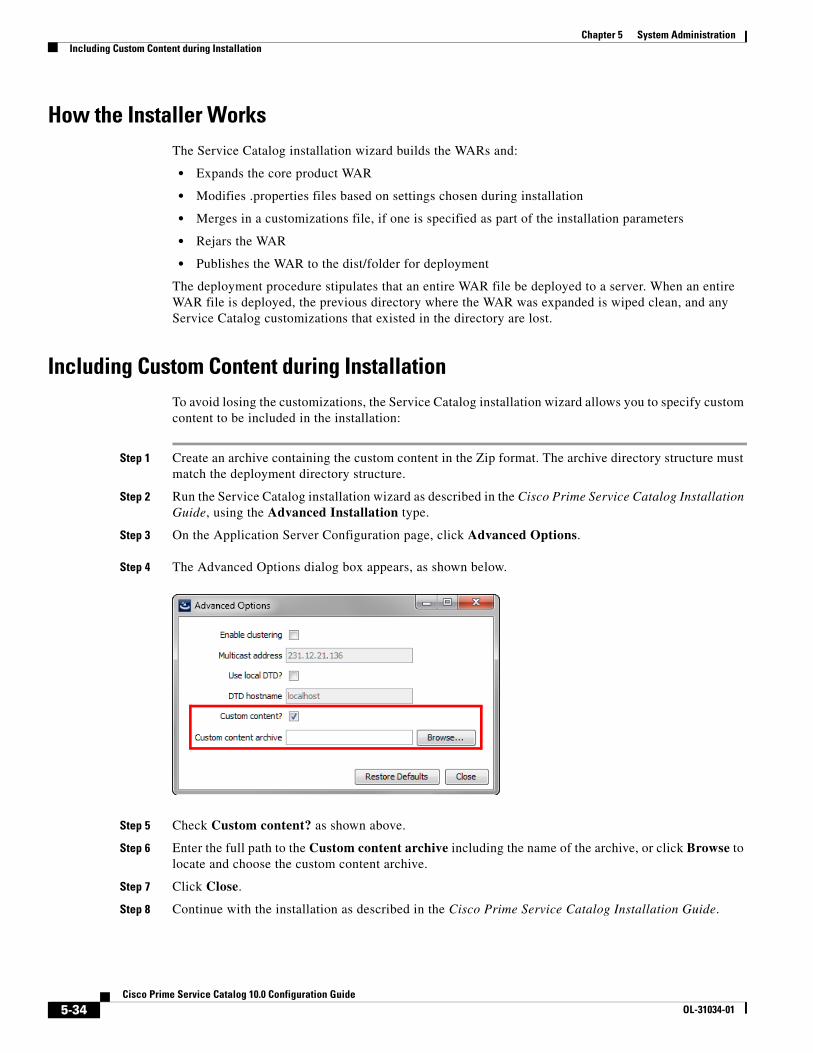
Chapter 5 System Administration Including Custom Content during Installation
How the Installer WorksThe Service Catalog installation wizard builds the WARs and:
• Expands the core product WAR
• Modifies .properties files based on settings chosen during installation
• Merges in a customizations file, if one is specified as part of the installation parameters
• Rejars the WAR
• Publishes the WAR to the dist/folder for deployment
The deployment procedure stipulates that an entire WAR file be deployed to a server. When an entire WAR file is deployed, the previous directory where the WAR was expanded is wiped clean, and any Service Catalog customizations that existed in the directory are lost.
Including Custom Content during InstallationTo avoid losing the customizations, the Service Catalog installation wizard allows you to specify custom content to be included in the installation:
Step 1 Create an archive containing the custom content in the Zip format. The archive directory structure must match the deployment directory structure.
Step 2 Run the Service Catalog installation wizard as described in the Cisco Prime Service Catalog Installation Guide, using the Advanced Installation type.
Step 3 On the Application Server Configuration page, click Advanced Options.
Step 4 The Advanced Options dialog box appears, as shown below.
Step 5 Check Custom content? as shown above.
Step 6 Enter the full path to the Custom content archive including the name of the archive, or click Browse to locate and choose the custom content archive.
Step 7 Click Close.
Step 8 Continue with the installation as described in the Cisco Prime Service Catalog Installation Guide.
5-34Cisco Prime Service Catalog 10.0 Configuration Guide
OL-31034-01

Chapter 5 System AdministrationIncluding Custom Content during Installation
While the Service Catalog installation wizard completes the installation, it extracts your custom content archive into the application deployment directory structure.
Implementation-Wide Custom Files
All customized files should be included in the customization archive. The following customized files may be required at all sites within an implementation:
Database Scripts
Modifying the database outside of the APIs provided by Cisco is strongly discouraged. However, some scripts may need to be executed directly against the database.
External Dictionaries
External Dictionaries are stored as database tables. Whenever these dictionaries are modified, DDL scripts need to be run to modify the corresponding table.
Patches
Customer Support may provide a SQL script as part of a patch or hotfix that needs to be run manually. Until a hotfix is included in a subsequent product release, it must be treated as a customization to be included in a software upgrade or reinstall.
Customizable Component Directory/Files
Custom style sheets, headers, footers RequestCenter.war\custom\*\custom.css
RequestCenter.war\custom\*\portal-custom-header.css
RequestCenter.war\custom\*\images\
RequestCenter.war\custom\*\header.html, footer.html, for all directories on which custom style sheets have been installed
ISF libraries RequestCenter.war\isfcode\*
Custom Classes RequestCenter.war\WEB-INF\classes\ (custom classes such as those related to Directory Integration customization)
Property Files edited by hand (such changes could also be site-specific)
newscale.properties
rcjms.properties
integrationserver.properties
newscalelog.properties
5-35Cisco Prime Service Catalog 10.0 Configuration Guide
OL-31034-01

Chapter 5 System Administration Including Custom Content during Installation
Catalog Deployer and Configuration ManagementA Service Catalog implementation typically consists of multiple sites, each of which plays a different role:
Managing Integrations, page 5-30 discussed management of configuration items that reside outside of the Service Catalog repository. Following the guidelines above will allow you to upgrade Service Catalog software without losing the customizations you have applied to that software. However, these guidelines do not address the need to migrate client-provided content—for example, service definitions and Person profiles—from one site to another. That capability is provided by Catalog Deployer.
The Catalog Deployer module provides configuration management for metadata (service definitions) and organizational data (people, organizations, and related entities) which is stored in the repository. Refer to Cisco Prime Service Catalog Designer Guide for Catalog Deployer documentation.
Recommended Process for Copying a DatabaseAt certain times during a deployment, it may be desirable to copy the Service Catalog OLTP database from one site to another. For example:
• When initially installing a test or production site, the complete development site may be copied to the new environments.
• After production has been in operation for a time, all of the user activity should be copied to a test environment, to allow realistic performance or volume studies.
Follow the procedures below to copy a Service Catalog OLTP database from one site to another.
Export Source
Step 1 Inform the users of expected downtime.
Step 2 Stop the Request Center and Service Link services in the source environment.
Step 3 Export the source database. Develop a naming convention that allows you to track the source of the data and the date of the export.
Step 4 If a system shutdown is not feasible, use the –consistent flag for the Oracle export.
Step 5 Restart the Request Center and Service Link services.
Site Usage
Development Service definitions are developed and unit tested; customizations are initially applied
Test A controlled environment, not interrupted by development activities, where Quality Assurance or other personnel test a Service Catalog
Production The live environment where the user community can request services from the Service Catalog and IT teams can fulfill service requests
5-36Cisco Prime Service Catalog 10.0 Configuration Guide
OL-31034-01

Chapter 5 System AdministrationConfiguring SSL for Service Link Inbound Documents
Import to Target
Step 1 Stop the Request Center and Service Link services in the target environment.
Step 2 Ensure you have a current backup copy of the target database.
Step 3 If required, copy the export file from its destination to a file system accessible to the target database server.
Step 4 Import data into the target database.
Step 5 For SQLServer, ensure that logins and users exist in the newly imported database match the credentials required for this instance of Service Catalog. If required, create a new login or associate an existing login with the database owner and ensure this user has appropriate permissions. For Oracle, ensure appropriate users exist in the newly imported database with privileges as specified in the Service Catalog installer.
Step 6 If the two sites are accessing two different Cognos reporting servers, update the entry in the CnfParams table that specifies the name of the “CognosServer” for this site and commit the update.
Step 7 Restart the Request Center and Service Link services in the target environment.
Step 8 Set the Administration > Entity Homes > SiteProtection “This Site Is” property to the current site. If Entity Homes are specified differently, or sites have different protection levels, make the changes manually and save your changes.
Step 9 If the two sites are connecting to two different LDAP directories, adjust the Directory Integration Data Source definition appropriately.
Step 10 Check and modify any connection properties for the Service Link agents as appropriate for the target environment.
Step 11 Perform any additional manual operations to adjust the data. For example, you may wish to add permissions to some people, groups, or organizations, or revoke permissions.
Step 12 Inform users that maintenance is complete.
Configuring SSL for Service Link Inbound Documents
OverviewEnabling SSL for the Service Link service involves:
• Getting a digital certificate that is either self-signed or signed by a known CA such as VeriSign.
• Installing the certificate, and
• Configuring a secure port number for the application server on which the Service Link service is running.
Procuring a certificate signed by a well-known Certificate Authority like VeriSign or Thawte has the benefit that most client programs already recognize the signer certificate from one of these Certificate Authorities. If you choose to use a self-signed certificate for your Service Link service, then you must exchange the signer certificate with all external systems that communicate with Service Link via web interface. For example, if an external system sends a response message to a Service Link agent which uses the http/ws adapter for its inbound adapter, then that external system acts as a client that connects to Service Link via an https URL, and will need to understand how to complete the trusted handshake for a successful SSL connection. In order to do this, the external system needs to recognize the signer
5-37Cisco Prime Service Catalog 10.0 Configuration Guide
OL-31034-01

Chapter 5 System Administration Configuring SSL for Service Link Inbound Documents
for the certificate used by the Service Link service. To achieve this, the signer certificate for Service Link must be imported into the Trusted Certificate Authority Keystore of the external system. More detailed instructions are given later in this section.
Note Service Link, as a server, does not support client certificate authentication during SSL handshake.
Secure vs. Nonsecure Port
Enabling SSL for Service Link turns on the secure port, but it does not turn off the nonsecure port for Service Link. If you choose not to turn off the nonsecure port, external systems can still communicate with Service Link via an http URL. If you decide to turn off the nonsecure port, all communications with the Service Link service must use the https URL.
It is possible to use both secure and nonsecure port for the Service Link service and control the access to the nonsecure port via another mechanism, such as a firewall system. For example, in a Two-JBoss-Server topology, the Request Center application is also a “client” of the Service Link service (which runs on a separate JBoss server). At runtime, Request Center needs to connect to the Service Link service via the URL http://<SL_servername>:6080. If the nonsecure port 6080 is turned off for the Service Link service, then Request Center must be configured to connect to Service Link via an https address, that is, https://<SL_servername>:6443. So, one possible scenario is that you turn on both nonsecure port 6080 and secure port 6443 for the Service Link service. Request Center can still connect to Service Link via http://<SL_servername>:6080, while other external systems must only communicate with Service Link via https://<SL_servername>:6443. You configure your firewall system to deny access to port 6080 from all external systems.
This section does NOT describe how to turn off a nonsecure port for the application server or how to configure a firewall system to deny access to a nonsecure port number. Please contact your system administrator, or the vendor of your application server product to obtain the information you need.
Clustered vs. Nonclustered Environment
If Service Link is deployed in a separate application server from Request Center (as in the case of a clustered WebLogic/WebSphere environment, or in the case of a Two-JBoss-Server topology), then to enable SSL for Service Link, you configure the certificate and secure port number only for the application server where Service Link is running.
Creating a Certificate KeystoreIt is assumed that you have managed to procure a digital certificate that can be used to secure the Service Link service. This certificate can either be self-signed or obtained through a third-party Certificate Authority like VeriSign. In either case, your digital certificate must be imported into a java keystore (that is, a jks file) that can be accessed by the application server. Furthermore, the signer certificate (aka the public key of your certificate) must be exported into a file in “Base64-encoded ASCII” format, so that it can be given to the external systems that want to communicate with Service Link service in SSL mode.
This document does not describe how to create a keystore file, and how to request a certificate for your web server or application server. The instructions in this section assume that you have already created a keystore file that contains the digital certificate to be used to enable SSL for the application server where Service Link is running. For ease of documentation, assume that your keystore file is named “slkeystore.jks”. It contains a certificate under the alias called “servicelink”. The password to open this keystore file is “slpassword”.
5-38Cisco Prime Service Catalog 10.0 Configuration Guide
OL-31034-01

Chapter 5 System AdministrationConfiguring SSL for Service Link Inbound Documents
Also assume that the signer certificate has been exported in “Base64-encoded ASCII” format into a file named “slsigner.cer”. A “Base64-encoded ASCII” format may look like the following example:
-----BEGIN CERTIFICATE-----MIICPDCCAaUCBE17w1cwDQYJKoZIhvcNAQEEBQAwZTELMAkGA1UEBhMCVVMxCzAJBgNVBAgTAkNBMRIwEAYDVQQHEwlTYW4gTWF0ZW8xETAPBgNVBAoTCG5ld1NjYWxlMQswCQYDVQQLEwJRQTEVMBMGA1UEAxMMS2hhbmcgTmd1eWVuMB4XDTExMDMxMjE5MDI0N1oXDTIxMDMwOTE5MDI0N1owZTELMAkGA1UEBhMCVVMxCzAJBgNVBAgTAkNBMRIwEAYDVQQHEwlTYW4gTWF0ZW8xETAPBgNVBAoTCG5ld1NjYWxlMQswCQYDVQQLEwJRQTEVMBMGA1UEAxMMS2hhbmcgTmd1eWVuMIGfMA0GCSqGSIb3DQEBAQUAA4GNADCBiQKBgQDhTxg2RwarD6Wn4iqYeOOk3ykfXzZiDArf/X63omXquTmN0Up+mg6oJmPAfqJAl7k4+Dn7dfVtAc4h8qra7PBeBU48zrzRqZd6VAK07rz++CilQto64mHXYVomb5vWPGeKA41j9vlvENj/tE/6++IqbwnxAqeZtY3EvEM7dcCWDwIDAQABMA0GCSqGSIb3DQEBBAUAA4GBAAaqCnfEAovyUf2S+oAXYDo5N387a035APsz5iiUM5oiKR/KW3oRz/v0P0I/o3n312kDIJ01111pl6qpZRtPEsr1b00Tu1cXfPmizEtz0ole606qDS+DzkS1+YYz2mLL2Zq40d1EPsMolyqyUmyq3GHaEnuhWemcv2aAwGFgbQYd-----END CERTIFICATE-----
Installing the Keystore for the Application ServerThe subsequent sections contain instructions for installing the certificate file and configuring SSL for each type of application server.
JBoss 7.1.1
Step 1 Stop the JBoss server where the Service Link application is running.
Step 2 Copy the “slkeystore.jks” file into the “<JBOSS_DIR>\ServiceLinkServer\configuration” directory, where <JBOSS_DIR> is the installation directory of the JBoss server where the Service Link application is deployed.
Step 3 Make a back up of file “<JBOSS_DIR>\ServiceLinkServer\configuration\standalone-full.xml”.
Step 4 Use a text editor to open file “standalone-full.xml”. Make sure you use a text editor that will not insert any special carriage return characters or any other formatting characters into the file.
Step 5 Search for the following line in file “standalone-full.xml”:
<connector name="http" protocol="HTTP/1.1" scheme="http" socket-binding="http"/>
Step 6 Insert the following three lines right below it:
<connector name="https" protocol="HTTP/1.1" scheme="https" socket-binding="https" secure="true">
<ssl name="ssl" key-alias="servicelink" password="slpassword" certificate-key-file="../ServiceLinkServer/configuration/slkeystore.jks"/>
</connector>
Note In the above entries, it is assumed that the name of your keystore file is “slkeystore.jks”, the alias for the certificate is “servicelink”, and the password to open the keystore file is “slpassword”.
Step 7 Search for the following string in file “standalone-full.xml”:
<socket-binding name="https" port=
Step 8 Make a note of the value for port number. This will be the secure port number used by the JBoss server in SSL mode.
5-39Cisco Prime Service Catalog 10.0 Configuration Guide
OL-31034-01

Chapter 5 System Administration Configuring SSL for Service Link Inbound Documents
Step 9 Stop the JBoss server where the Service Catalog application is running.
Step 10 Navigate to the “<JBOSS_DIR>\RequestCenterServer\deployments\RequestCenter.war\WEB-INF\classes\config” directory.
Step 11 Use a text editor to open file “newscale.properties”.
Step 12 Search for the following parameter:
isee.base.url=
Note The Request Center application is communicating with the Service Link application via this URL. This Service Link URL is now SSL enabled, and thus the address needs to be changed to an https address, and the port number needs to be changed to the secure port number used by the JBoss server for Service Link.
Step 13 Change the value for this parameter from http://<hostname>:<nonsecure_port_number> to https://<hostname>:<secure_port_number>.
Step 14 Copy file “slsigner.cer” to the “<JAVA_HOME>\jre\lib\security” directory, where <JAVA_HOME> is the JDK 6 installation directory. (Note: It is assumed that file “slsigner.cer” contains the CA certificate.)
Step 15 Open a Command Prompt window or a Console window and navigate to the “<JAVA_HOME>\jre\lib\security” directory.
Step 16 Execute the following command to import the CA root certification into the trusted certificate keystore used by JDK 6:
<JAVA_HOME>\bin\keytool -import -trustcacerts -file slsigner.cer -alias servicelink -keystore cacerts -storepass changeit
Note In the above entries, it is assumed that “slsigner.cer” is the name of the file that contains the CA root certificate, “servicelink” is the alias, “cacerts” is the name of the trusted keystore file for JDK 6, and “changeit” is the password to open the “cacerts” keystore file.
Step 17 Start up both RequestCenterServer and ServiceLinkServers now.
Step 18 Connect to the Request Center URL as an administrator user, or as a user who can access the Service Link module.
Step 19 Open the Service Link home page.
Step 20 On the left side, under the Service Link Status section, verify that the connection is in green status, and both the SSL icon and the secure port number display.
Step 21 Any external system that sends an inbound document to the Service Link agent that uses the HTTP/WS adapter will need to be updated as follows:
a. The inbound routing URL needs to use the https address and the secure port number.
b. The signer certificate for Service Link (contained in file slsigner.cer) will need to be imported into the trusted CA root certificate keystore of the external system.
5-40Cisco Prime Service Catalog 10.0 Configuration Guide
OL-31034-01
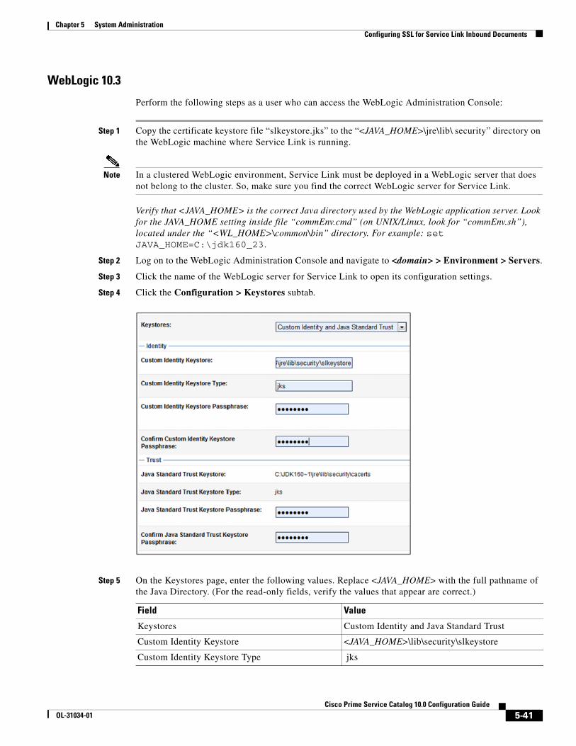
Chapter 5 System AdministrationConfiguring SSL for Service Link Inbound Documents
WebLogic 10.3
Perform the following steps as a user who can access the WebLogic Administration Console:
Step 1 Copy the certificate keystore file “slkeystore.jks” to the “<JAVA_HOME>\jre\lib\ security” directory on the WebLogic machine where Service Link is running.
Note In a clustered WebLogic environment, Service Link must be deployed in a WebLogic server that does not belong to the cluster. So, make sure you find the correct WebLogic server for Service Link.
Verify that <JAVA_HOME> is the correct Java directory used by the WebLogic application server. Look for the JAVA_HOME setting inside file “commEnv.cmd” (on UNIX/Linux, look for “commEnv.sh”), located under the “<WL_HOME>\common\bin” directory. For example: set JAVA_HOME=C:\jdk160_23.
Step 2 Log on to the WebLogic Administration Console and navigate to <domain> > Environment > Servers.
Step 3 Click the name of the WebLogic server for Service Link to open its configuration settings.
Step 4 Click the Configuration > Keystores subtab.
Step 5 On the Keystores page, enter the following values. Replace <JAVA_HOME> with the full pathname of the Java Directory. (For the read-only fields, verify the values that appear are correct.)
Field Value
Keystores Custom Identity and Java Standard Trust
Custom Identity Keystore <JAVA_HOME>\lib\security\slkeystore
Custom Identity Keystore Type jks
5-41Cisco Prime Service Catalog 10.0 Configuration Guide
OL-31034-01

Chapter 5 System Administration Configuring SSL for Service Link Inbound Documents
For the Java Standard Trust Keystore Passphrase: It is assumed that the password for the “cacerts” keystore file is still the default value of “changeit”. Replace it with the correct value if the password for “cacerts” has been changed in your environment.
Step 6 Click Save.
Step 7 Click the Configuration > SSL subtab.
Step 8 On the SSL page, enter the following values:
Step 9 Click Save.
Step 10 Click the Configuration > General subtab.
Custom Identity Keystore Passphrase slpassword
Confirm Custom Identity Keystore Passphrase slpassword
Java Standard Trust Keystore <JAVA_HOME>\lib\security\cacerts
Java Standard Trust Keystore Type jks
Java Standard Trust Keystore Passphrase changeit
Confirm Java Standard Trust Keystore Passphrase changeit
Identity and Trust Locations Keystores
Private Key Alias servicelink
Private Key Passphrase slpassword
Confirm Private Key Passphrase slpassword
5-42Cisco Prime Service Catalog 10.0 Configuration Guide
OL-31034-01

Chapter 5 System AdministrationConfiguring SSL for Service Link Inbound Documents
Step 11 On the General page, enter the following values:
• Check the SSL Listen Port Enabled check box.
• SSL Listen Port = <enter an available port number, for example 9443>.
Step 12 Click Save.
Step 13 Restart the WebLogic server where Service Link is deployed.
Step 14 Look in the log file “<WL_servername>.out” for messages similar to the following, to ensure that the WebLogic server has started up in the secure port (9443):
<Notice> <Security> <BEA-090171> <Loading the identity certificate and private key stored under the alias hydra2 from the jks keystore file C:\jdk160_23\jre\lib\security\slkeystore.><Notice> <Server> <BEA-002613> <Channel "DefaultSecure" is now listening on 192.168.21.72:9443 for protocols iiops, t3s, ldaps, https.>
Your Service Link service is now SSL-enabled.
Step 15 Skip this step if you have already created the file “slsigner.cer” that contains the signer certificate for the servicelink certificate. Otherwise, you can perform the following procedure to export the signer certificate. There are several methods to export the signer certificate; the following procedure is just one way to do it using the “keytool.exe” utility that comes with the Sun JDK 6 installation.
a. Execute the following commands on a Command Prompt window:
cd <JAVA_HOME>\jre\lib\security<JAVA_HOME>\bin\keytool -export -rfc -file slsigner.cer -alias servicelink -keystore slkeystore.jks -storepass slpassword
b. To verify that file “slsigner.cer” is good, execute:
<JAVA_HOME>\bin\keytool –printcert –file slsigner.cer
5-43Cisco Prime Service Catalog 10.0 Configuration Guide
OL-31034-01

Chapter 5 System Administration Configuring SSL for Service Link Inbound Documents
Step 16 If you decide to disable the nonsecure port for the Service Link service, send the file “slsigner.cer” to the system administrator who manages the external system which communicates with the Service Link service. Two things will need to be configured for that external system:
a. The Service Link URL needs to be changed from an http address to an https address with the secure port number. For example, previously, the Service Link URL may be:
http://<sl_servername>:9001/IntegrationServer/ishttplistener/ <agent_name>
It must now be changed to:
https://<sl_servername>:9443/IntegrationServer/ishttplistener/<agent_name>
b. The signer certificate of the servicelink certificate (i.e. the contents of file “slsigner.cer”) needs to be imported into the Java Trusted Certificate Authority Keystore of the external system, so that a trusted handshake can be established during the SSL connection with the Service Link service.
For a clustered WebLogic environment only
Step 1 If you decide to disable the nonsecure port for the Service Link service, then you must also import the signer certificate into the Java Trusted Certificate Authority Keystore of the Request Center service. This is because Service Link runs a separate WebLogic server that does not belong to the cluster. (Only Request Center and the Business Engine can be installed on the cluster.) Request Center acts as a “client” that connects to the Service Link service at runtime. Complete the following procedure to import the signer certificate into the Java Trusted CA Keystore for Request Center:
a. Log on to one of the nodes of the WebLogic cluster where Request Center application is running.
b. Locate the file “cacerts” in the directory “<JAVA_HOME>\jre\lib\security”, where <JAVA_HOME> is the root directory of the Sun JDK 6 installation. This file is the Trusted CA Keystore that comes with the Sun JDK 6 installation.
Make sure that <JAVA_HOME> is the correct Java directory used by your WebLogic application server. To verify this, look for the JAVA_HOME setting inside file “commEnv.cmd” (on UNIX/Linux, look for “commEnv.sh”), located under the “<WL_HOME>\common\bin” directory. For example:
set JAVA_HOME=C:\jdk160_23.
c. Copy the file “slsigner.cert” to the “<JAVA_HOME>\jre\lib\security” directory.
d. Import the signer certificate into the “cacerts” keystore by executing the following commands on a Command Prompt window:
cd <JAVA_HOME>\jre\lib\security<JAVA_HOME>\bin\keytool -import -trustcacerts -alias servicelink –noprompt -file slsigner.cer -keystore cacerts -storepass changeit
In the command above, the password for the “cacerts” keystore file is still the default value of “changeit”. Replace it with the correct value if the password for “cacerts” has been changed in your environment.
e. Copy file “cacerts” that you just updated in the last step to the “<JAVA_HOME>\jre\lib\security” directory on every node in the WebLogic cluster where Request Center is deployed. For example, if your WebLogic cluster contains three nodes, and each node is a separate machine, then copy the file “cacerts” from this machine to the other two machines.
f. Modify file “newscale.properties” under the directory “<BEA_HOME>\ user_projects\ domains\<domain_name>\servers\<servername>\stage\ RequestCenter\config" as follows:
5-44Cisco Prime Service Catalog 10.0 Configuration Guide
OL-31034-01

Chapter 5 System AdministrationConfiguring SSL for Service Link Inbound Documents
Search for the following parameter:
isee.base.url=http://<hostname>:9001
and change it to:
isee.base.url=https://<hostname>:9443
g. Repeat Step (f) for every node in the WebLogic cluster where Request Center is deployed.
h. Restart the WebLogic cluster for Request Center.
Step 2 To avoid Step 1 entirely, you may decide to turn on both the nonsecure and secure ports for the Service Link service. This way the Request Center application can still connect to Service Link using the nonsecure URL (http://<hostname>:9001). But you may want to consider taking some measures (such as a firewall system) to block access to the nonsecure port from all external systems.
WebSphere 7
At installation time, the WebSphere setup program automatically configures both the nonsecure port (WC_defaulthost) and secure port (WC_defaulthost_secure) for your WebSphere server. It also automatically installs a self-signed certificate (with a 1-year expiration date) under the alias named “default” for your WebSphere server. You can choose to do one of the following:
• Use the “default” self-signed certificate for your WebSphere server where Service Link is running.
• Use the certificate in the “slkeystore.jks” file that you created at the beginning of this chapter, or
• Create another self-signed certificate for your WebSphere server.
This chapter does not describe how to create a self-signed certificate for your WebSphere server. However, the subsequent sections contain the instructions for the following: a) how to use the existing “default” certificate, or b) how to use the certificate in the “slkeystore.jks” file.
Before choosing which certificate to use, you must first perform the steps described in the next section to find out what the secure port number and what keystore are used by the WebSphere server on which Service Link is running.
Locating Secure Port Number and Keystore for WebSphere Server
Step 1 Log on to the WebSphere Administration Console, and navigate to Servers > Application servers.
Step 2 Click the name of your WebSphere server where Service Link is deployed.
In a clustered WebSphere environment, Service Link must be deployed in a WebSphere server that does not belong to the cluster. Make sure you find the correct WebSphere server for Service Link.
Step 3 On the Configuration tab, expand the “Ports” node.
5-45Cisco Prime Service Catalog 10.0 Configuration Guide
OL-31034-01
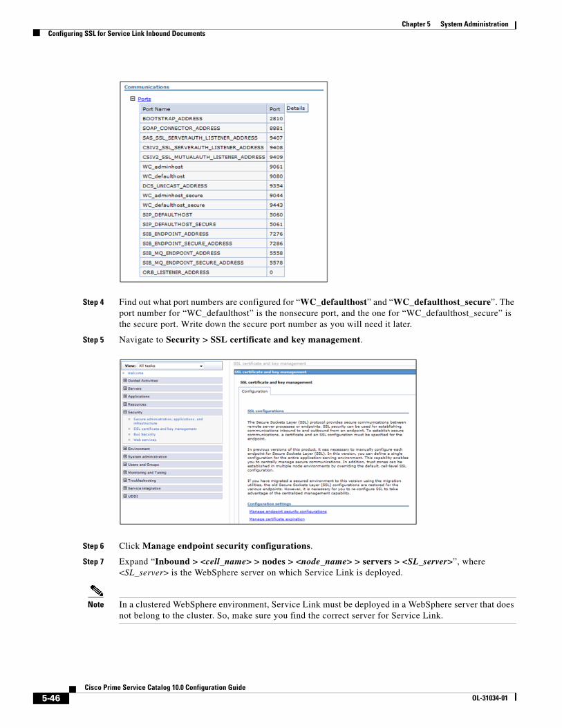
Chapter 5 System Administration Configuring SSL for Service Link Inbound Documents
Step 4 Find out what port numbers are configured for “WC_defaulthost” and “WC_defaulthost_secure”. The port number for “WC_defaulthost” is the nonsecure port, and the one for “WC_defaulthost_secure” is the secure port. Write down the secure port number as you will need it later.
Step 5 Navigate to Security > SSL certificate and key management.
Step 6 Click Manage endpoint security configurations.
Step 7 Expand “Inbound > <cell_name> > nodes > <node_name> > servers > <SL_server>”, where <SL_server> is the WebSphere server on which Service Link is deployed.
Note In a clustered WebSphere environment, Service Link must be deployed in a WebSphere server that does not belong to the cluster. So, make sure you find the correct server for Service Link.
5-46Cisco Prime Service Catalog 10.0 Configuration Guide
OL-31034-01
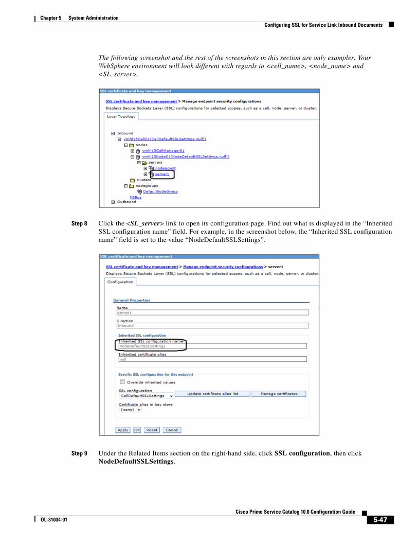
Chapter 5 System AdministrationConfiguring SSL for Service Link Inbound Documents
The following screenshot and the rest of the screenshots in this section are only examples. Your WebSphere environment will look different with regards to <cell_name>, <node_name> and <SL_server>.
Step 8 Click the <SL_server> link to open its configuration page. Find out what is displayed in the “Inherited SSL configuration name” field. For example, in the screenshot below, the “Inherited SSL configuration name” field is set to the value “NodeDefaultSSLSettings”.
Step 9 Under the Related Items section on the right-hand side, click SSL configuration, then click NodeDefaultSSLSettings.
5-47Cisco Prime Service Catalog 10.0 Configuration Guide
OL-31034-01
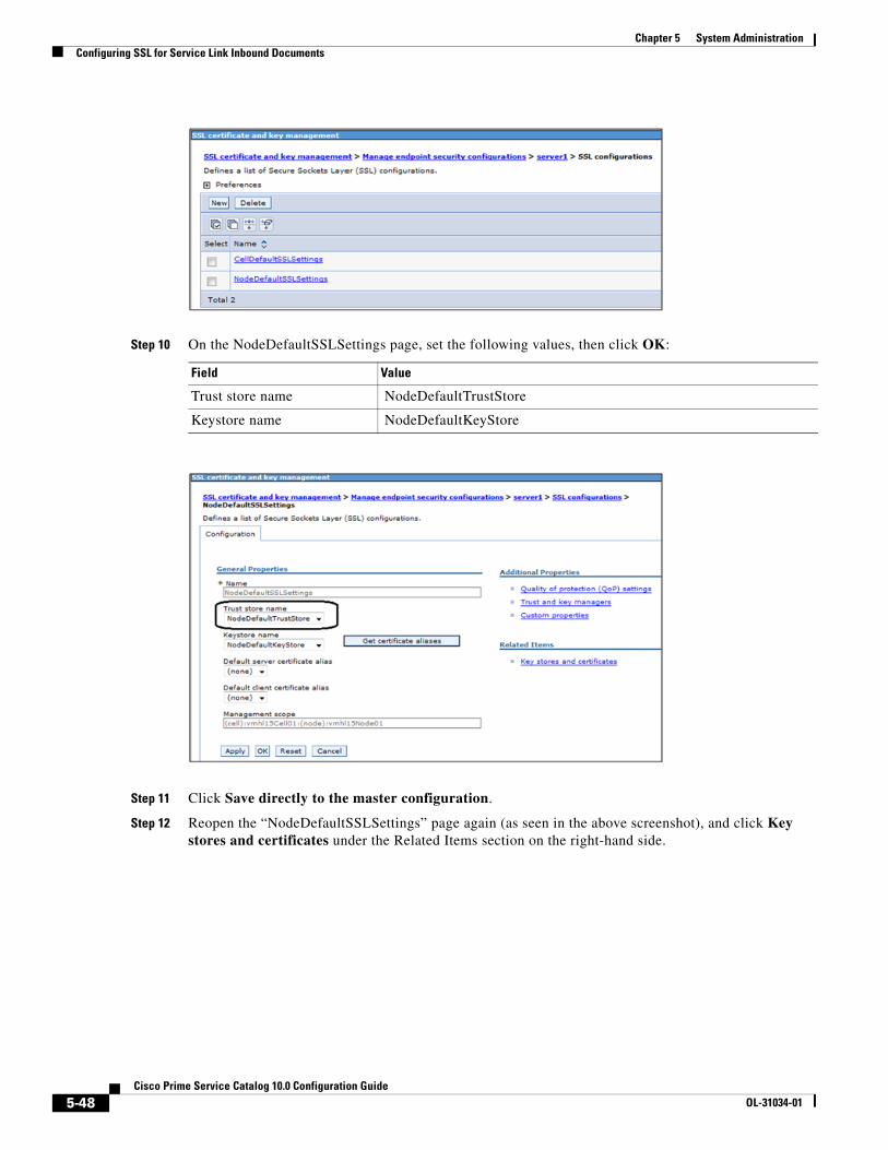
Chapter 5 System Administration Configuring SSL for Service Link Inbound Documents
Step 10 On the NodeDefaultSSLSettings page, set the following values, then click OK:
Step 11 Click Save directly to the master configuration.
Step 12 Reopen the “NodeDefaultSSLSettings” page again (as seen in the above screenshot), and click Key stores and certificates under the Related Items section on the right-hand side.
Field Value
Trust store name NodeDefaultTrustStore
Keystore name NodeDefaultKeyStore
5-48Cisco Prime Service Catalog 10.0 Configuration Guide
OL-31034-01

Chapter 5 System AdministrationConfiguring SSL for Service Link Inbound Documents
Step 13 Click NodeDefaultKeyStore.
Step 14 Under the Additional Properties section, click Personal certificates.
Step 15 Look for the alias “default”, and verify that the certificate has not expired.
Step 16 If the “default” certificate has not expired and you want to use it for your Service Link service, then proceed to the “Using the “default” certificate” section below.
5-49Cisco Prime Service Catalog 10.0 Configuration Guide
OL-31034-01

Chapter 5 System Administration Configuring SSL for Service Link Inbound Documents
Step 17 On the other hand, if you decide to use the certificate that you created in file “slkeystore.jks” at the beginning of this section, then skip to the “Using the “slkeystore.jks” file” section on page 5-51.
Using the “default” certificate
Step 1 On the Personal certificates page, check the check box in front of “default” alias, then click Extract.
Step 2 Enter the following values:
Step 3 Click OK.
Step 4 Restart the WebSphere server where Service Link is deployed.
Step 5 Look in the log file “SystemOut.log” for messages similar to the following, to ensure that the WebSphere server has started up in secure port that is, port 9443):
TCPC0001I: TCP Channel TCP_4 is listening on host * (IPv4) port 9443.CHFW0019I: The Transport Channel Service has started chain WCInboundDefaultSecure.
Your Service Link service is now SSL-enabled, and is using the “default” certificate.
Field Value
Certificate alias to extract default
Certificate file name Enter a pathname such as C:\temp\default_signer.cer>
Data type Base64-encoded ASCII data
5-50Cisco Prime Service Catalog 10.0 Configuration Guide
OL-31034-01
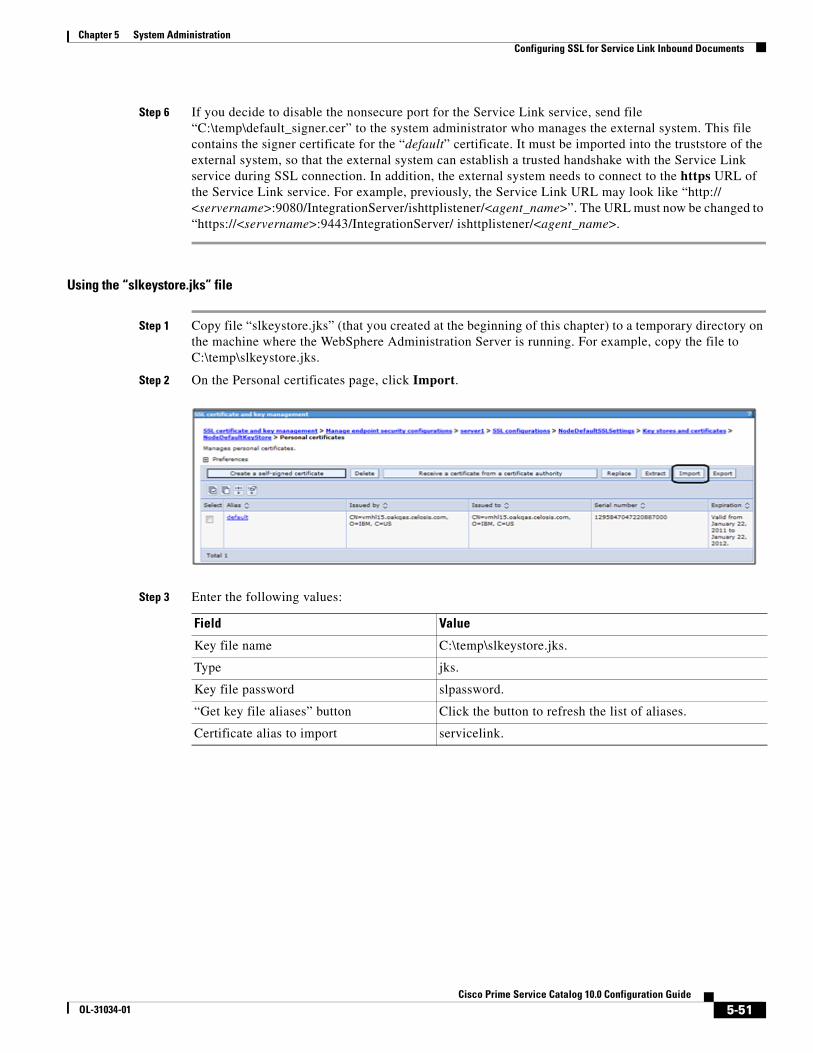
Chapter 5 System AdministrationConfiguring SSL for Service Link Inbound Documents
Step 6 If you decide to disable the nonsecure port for the Service Link service, send file “C:\temp\default_signer.cer” to the system administrator who manages the external system. This file contains the signer certificate for the “default” certificate. It must be imported into the truststore of the external system, so that the external system can establish a trusted handshake with the Service Link service during SSL connection. In addition, the external system needs to connect to the https URL of the Service Link service. For example, previously, the Service Link URL may look like “http:// <servername>:9080/IntegrationServer/ishttplistener/<agent_name>”. The URL must now be changed to “https://<servername>:9443/IntegrationServer/ ishttplistener/<agent_name>.
Using the “slkeystore.jks” file
Step 1 Copy file “slkeystore.jks” (that you created at the beginning of this chapter) to a temporary directory on the machine where the WebSphere Administration Server is running. For example, copy the file to C:\temp\slkeystore.jks.
Step 2 On the Personal certificates page, click Import.
Step 3 Enter the following values:
Field Value
Key file name C:\temp\slkeystore.jks.
Type jks.
Key file password slpassword.
“Get key file aliases” button Click the button to refresh the list of aliases.
Certificate alias to import servicelink.
5-51Cisco Prime Service Catalog 10.0 Configuration Guide
OL-31034-01
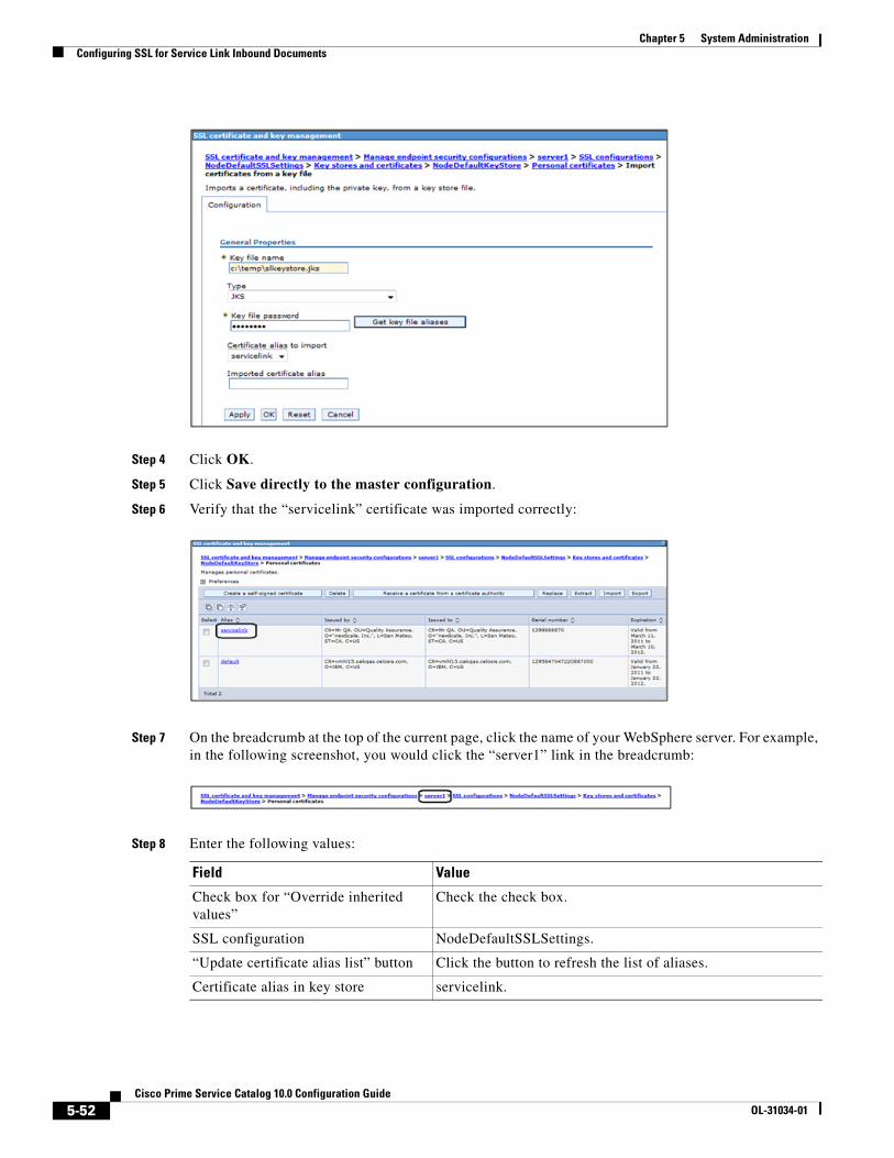
Chapter 5 System Administration Configuring SSL for Service Link Inbound Documents
Step 4 Click OK.
Step 5 Click Save directly to the master configuration.
Step 6 Verify that the “servicelink” certificate was imported correctly:
Step 7 On the breadcrumb at the top of the current page, click the name of your WebSphere server. For example, in the following screenshot, you would click the “server1” link in the breadcrumb:
Step 8 Enter the following values:
Field Value
Check box for “Override inherited values”
Check the check box.
SSL configuration NodeDefaultSSLSettings.
“Update certificate alias list” button Click the button to refresh the list of aliases.
Certificate alias in key store servicelink.
5-52Cisco Prime Service Catalog 10.0 Configuration Guide
OL-31034-01

Chapter 5 System AdministrationConfiguring SSL for Service Link Inbound Documents
Step 9 Click OK.
Step 10 Click Save directly to the master configuration.
Step 11 Restart the WebSphere server where Service Link is deployed.
Step 12 Look in the log file “SystemOut.log” for messages similar to the following, to ensure that the WebSphere server has started up in secure port (i.e. port 9443):
TCPC0001I: TCP Channel TCP_4 is listening on host * (IPv4) port 9443.CHFW0019I: The Transport Channel Service has started chain WCInboundDefaultSecure.
Your Service Link service is now SSL-enabled, and is using the “servicelink” certificate that you imported from file “slkeystore.jks”.
Step 13 If you decide to disable the nonsecure port for the Service Link service, send file “slsigner.cer” (that you created at the beginning of this chapter) to the system administrator who manages the external system. That file contains the signer certificate for the “servicelink” certificate. It must be imported into the truststore of the external system, so that the external system can establish a trusted handshake with the Service Link service during SSL connection. In addition, the external system needs to connect to the https URL of the Service Link application. For example, previously, the Service Link URL may look like “http://<servername>:9080/ IntegrationServer/ ishttplistener/<agent_name>”. The URL must now be changed to “https://<servername>:9443/IntegrationServer/ishttplistener/<agent_name>”.
Step 14 If you have not created the file “slsigner.cer”, you can do so now, by performing the following procedure:
a. Navigate back to the Key stores and certificates > NodeDefaultKeyStore > Personal certificates page.
5-53Cisco Prime Service Catalog 10.0 Configuration Guide
OL-31034-01
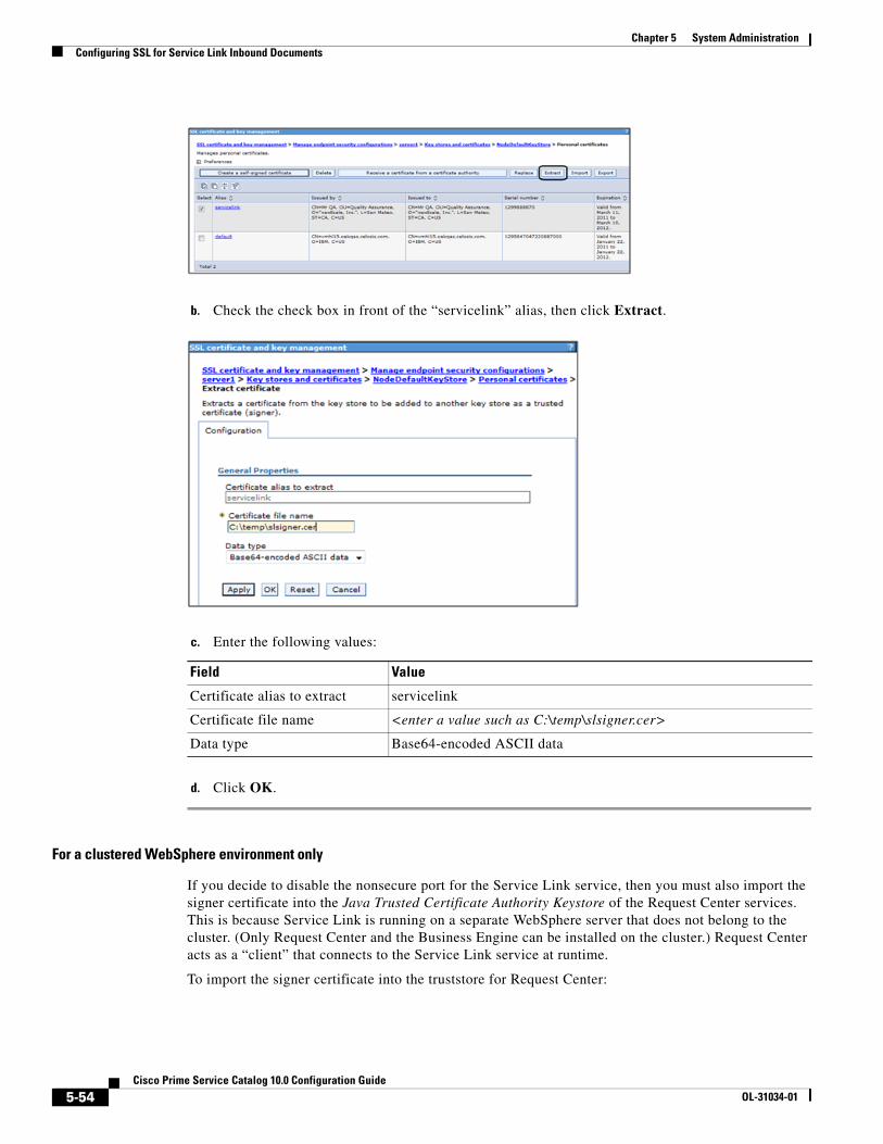
Chapter 5 System Administration Configuring SSL for Service Link Inbound Documents
b. Check the check box in front of the “servicelink” alias, then click Extract.
c. Enter the following values:
d. Click OK.
For a clustered WebSphere environment only
If you decide to disable the nonsecure port for the Service Link service, then you must also import the signer certificate into the Java Trusted Certificate Authority Keystore of the Request Center services. This is because Service Link is running on a separate WebSphere server that does not belong to the cluster. (Only Request Center and the Business Engine can be installed on the cluster.) Request Center acts as a “client” that connects to the Service Link service at runtime.
To import the signer certificate into the truststore for Request Center:
Field Value
Certificate alias to extract servicelink
Certificate file name <enter a value such as C:\temp\slsigner.cer>
Data type Base64-encoded ASCII data
5-54Cisco Prime Service Catalog 10.0 Configuration Guide
OL-31034-01
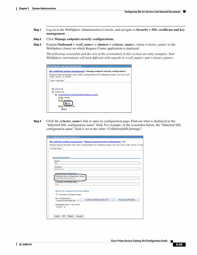
Chapter 5 System AdministrationConfiguring SSL for Service Link Inbound Documents
Step 1 Log on to the WebSphere Administration Console, and navigate to Security > SSL certificate and key management.
Step 2 Click Manage endpoint security configurations.
Step 3 Expand Outbound > <cell_name> > clusters > <cluster_name>, where <cluster_name> is the WebSphere cluster on which Request Center application is deployed.
The following screenshot and the rest of the screenshots in this section are only examples. Your WebSphere environment will look different with regards to <cell_name> and <cluster_name>.
Step 4 Click the <cluster_name> link to open its configuration page. Find out what is displayed in the “Inherited SSL configuration name” field. For example, in the screenshot below, the “Inherited SSL configuration name” field is set to the value “CellDefaultSSLSettings”.
5-55Cisco Prime Service Catalog 10.0 Configuration Guide
OL-31034-01

Chapter 5 System Administration Configuring SSL for Service Link Outbound Documents
Step 5 Under the Related Items section on the right-hand side, click SSL configuration, then click CellDefaultSSLSettings.
Step 6 Check the value in the field “Trust store name”. For example, the value is set to “CellDefaultTrustStore”.
Step 7 Under the Related Items on the right-hand side, click Key stores and certificates.
Step 8 Click CellDefaultTrustStore.
Step 9 On the right-hand side, click Signer certificates.
Step 10 Click Add.
Step 11 Enter the following values, then click OK:
Step 12 Click Save directly to the master configuration.
Step 13 Modify file “newscale.properties” under the directory “RequestCenter.war\WEB-INF\classes\config\” as follows:
Search for the following parameter:
isee.base.url=http://<hostname>:9080
and change to:
isee.base.url=https://<hostname>:9443
Step 14 Repeat Step 13 for every node in the WebSphere cluster where Request Center is deployed.
Step 15 Restart the WebSphere cluster for Request Center.
Step 16 To avoid Step 1 above, you may decide to turn on both nonsecure port and secure ports for the Service Link service. This way the Request Center application (running in the WebSphere cluster) can still connect to Service Link using the nonsecure URL (http://<hostname>:9080). But you may want to consider taking some measures (such as a firewall system) to block access to the nonsecure port from all external systems.
Configuring SSL for Service Link Outbound Documents
OverviewWhen a Service Link agent uses the HTTP/WS adapter to send an outbound message to an external system, it acts as a client that posts http requests or web services request to the external web server. If the external web server is SSL-enabled, Service Link may require some configuration in order to establish a secure connection with that web server.
• The Outbound URL of the Service Link agent must point to the https address with the secured port number of the external web server.
Field Value
Alias servicelink
File name C:\slsigner.cer
Data type Base64-encoded ASCII data
5-56Cisco Prime Service Catalog 10.0 Configuration Guide
OL-31034-01

Chapter 5 System AdministrationConfiguring SSL for Service Link Outbound Documents
• To establish a trusted handshake via SSL, the client (that is, the Service Link service) must have a valid signer certificate (the public key certificate) that can validate the digital certificate of the external web server. If the certificate of the external web server is not signed by a well-known Certificate Authority (CA) such as VeriSign, then most likely during the SSL handshake, Service Link will not be able to validate the external web server certificate, and the connection will fail. If this is the case, the signer certificate must be imported into the Trusted Certificate Authority Keystore used by the Service Link service.
Note If Service Link is connecting to multiple SSL-enabled web servers, it may be necessary to import multiple signer certificates, one for each external web server. Service Link, as a client, does not support Client Certificate Authentication during SSL handshake.
The following sections describe the configuration procedure in more detail.
Outbound URL
Step 1 Log on to Cisco Prime Service Catalog as a user who can access Service Link.
Step 2 Navigate to the Service Link module and click the Manage Integrations tab.
Step 3 Choose the agent that you want to configure.
Step 4 Open the Outbound Properties page of the agent.
Step 5 In the HttpOutboundAdapter.RoutingURL field, enter the https address with the secured port number, for example, https://192.168.21.202:8444/HTTPSimulator/.
Step 6 Set the value for the HttpOutboundAdapter.AcceptUntrustedURL field to false to ensure a secure connection.
Step 7 Click Save.
Step 8 Open the Control Agents tab, and restart the agent.
Importing the Signer Certificate to a Trusted CA KeystoreThe instructions for importing the signer certificate depend on the application server (“JBoss 7.1.1”, “WebLogic 10.3”, or “WebSphere 7”) that Service Link is running on. Before following the application server-specific instructions, you must complete the following step:
5-57Cisco Prime Service Catalog 10.0 Configuration Guide
OL-31034-01

Chapter 5 System Administration Configuring SSL for Service Link Outbound Documents
• Get the signer certificate of the external web server in a file. To do this, you can contact the system administrator who manages the external web server, and ask him/her to export the signer certificate (the public key) of the digital certificate used to secure that web server. The signer certificate must be exported in the “Base64-encoded ASCII” format. The following is an example of what a Base64-encoded signer certificate looks like:
-----BEGIN CERTIFICATE-----MIICPDCCAaUCBE17w1cwDQYJKoZIhvcNAQEEBQAwZTELMAkGA1UEBhMCVVMxCzAJBgNVBAgTAkNBMRIwEAYDVQQHEwlTYW4gTWF0ZW8xETAPBgNVBAoTCG5ld1NjYWxlMQswCQYDVQQLEwJRQTEVMBMGA1UEAxMMS2hhbmcgTmd1eWVuMB4XDTExMDMxMjE5MDI0N1oXDTIxMDMwOTE5MDI0N1owZTELMAkGA1UEBhMCVVMxCzAJBgNVBAgTAkNBMRIwEAYDVQQHEwlTYW4gTWF0ZW8xETAPBgNVBAoTCG5ld1NjYWxlMQswCQYDVQQLEwJRQTEVMBMGA1UEAxMMS2hhbmcgTmd1eWVuMIGfMA0GCSqGSIb3DQEBAQUAA4GNADCBiQKBgQDhTxg2RwarD6Wn4iqYeOOk3ykfXzZiDArf/X63omXquTmN0Up+mg6oJmPAfqJAl7k4+Dn7dfVtAc4h8qra7PBeBU48zrzRqZd6VAK07rz++CilQto64mHXYVomb5vWPGeKA41j9vlvENj/tE/6++IqbwnxAqeZtY3EvEM7dcCWDwIDAQABMA0GCSqGSIb3DQEBBAUAA4GBAAaqCnfEAovyUf2S+oAXYDo5N387a035APsz5iiUM5oiKR/KW3oRz/v0P0I/o3n312kDIJ01111pl6qpZRtPEsr1b00Tu1cXfPmizEtz0ole606qDS+DzkS1+YYz2mLL2Zq40d1EPsMolyqyUmyq3GHaEnuhWemcv2aAwGFgbQYd-----END CERTIFICATE-----
Note If the signer of the external web server certificate is a well-known Certificate Authority like VeriSign or Thawte, then most likely, you can skip this step since Sun JDK already recognizes many well-known CA signers. On WebSphere, you still need to complete this step because the WebSphere truststore does not contain third-party Certificate Authority signers.
JBoss 7.1.1
Perform the following steps as the “administrator” user of the Service Link machine:
Step 1 Copy the signer certificate file (of the external system) to a temporary directory on the Service Link machine. For example, if the signer certificate file is called “extws.cer”, then copy this file to “C:\temp\extws.cer” on the Service Link machine.
Step 2 On the Service Link machine, locate the file “cacerts” in the directory “<JAVA_HOME>\jre\lib\security”, where <JAVA_HOME> is the root directory of the Sun JDK 6 installation. This file is the Trusted CA Keystore that comes with the Sun JDK 6 installation.
Step 3 Import the signer certificate into the “cacerts” keystore by executing the following commands in a Command Prompt window or a Console window:
cd <JAVA_HOME>\jre\lib\security
<JAVA_HOME>\bin\keytool -import -trustcacerts -alias extws –noprompt -file C:\temp\extws.cer -keystore cacerts -storepass changeit
Note In the “keytool” command above, it is assumed that the password for the “cacerts” keystore file is still the default value of “changeit”. Replace this with the correct value for the password in your environment. For the –alias parameter, you can replace the value “extws” with an appropriate alias you plan to use for this signer certificate. If you import multiple signer certificates, make sure to assign a unique alias name to each signer certificate.
Step 4 Restart the Service Link service.
5-58Cisco Prime Service Catalog 10.0 Configuration Guide
OL-31034-01

Chapter 5 System AdministrationConfiguring SSL for Service Link Outbound Documents
WebLogic 10.3
Perform the following steps as the “root” user (if on UNIX/Linux) or the “administrator” user (if on Windows) of the WebLogic machine:
Step 1 Copy the signer certificate file (of the external system) to a temporary directory on the WebLogic machine where Service Link service is running. For example, if the signer certificate file is called “extws.cer”, then copy this file to “/tmp/extws.cer” on the Service Link machine.
In a clustered WebLogic environment, Service Link must be deployed in a WebLogic server that does not belong to the cluster. So, make sure you find the correct WebLogic server for Service Link.
Step 2 On the Service Link machine, locate file “cacerts” in the directory “<JAVA_HOME>/jre/lib/security”, where <JAVA_HOME> is the root directory of the Sun JDK 6 installation. This file is the Trusted CA Keystore that comes with the Sun JDK 6 installation.
Make sure that <JAVA_HOME> is the correct Java directory used by your WebLogic application server. To verify this, look for the JAVA_HOME setting inside file “commEnv.sh” (on Windows, look for “commEnv.cmd”), located under the “<WL_HOME>/common/bin” directory. For example: JAVA_HOME=“/opt/jdk1.6.0_23”.
Step 3 Import the signer certificate into the “cacerts” keystore by executing the following commands in a Command Prompt window:
cd <JAVA_HOME>/jre/lib/security
<JAVA_HOME>/bin/keytool -import -trustcacerts -alias extws –noprompt -file /tmp/extws.cer -keystore cacerts -storepass changeit
Note In the “keytool” command above, it is assumed that the password for the “cacerts” keystore file is still the default value of “changeit”. Replace this with the correct value for the password in your environment. For the –alias parameter, you can replace the value “extws” with an appropriate alias you plan to use for this signer certificate. If you import multiple signer certificates, make sure to assign a unique alias name to each signer certificate.
Step 4 Restart the WebLogic server where Service Link is deployed.
WebSphere 7
Perform the following steps as a user who can access the WebSphere Administration Console:
Step 1 Copy the signer certificate file (of the external system) to a temporary directory on the machine where the WebSphere Administration Server is running. For example, if the signer certificate file is called “extws.cer”, then copy this file to “C:\temp\extws.cer” on the WebSphere machine.
Step 2 Log on to the WebSphere Administration Console, and navigate to Security > SSL certificate and key management.
5-59Cisco Prime Service Catalog 10.0 Configuration Guide
OL-31034-01
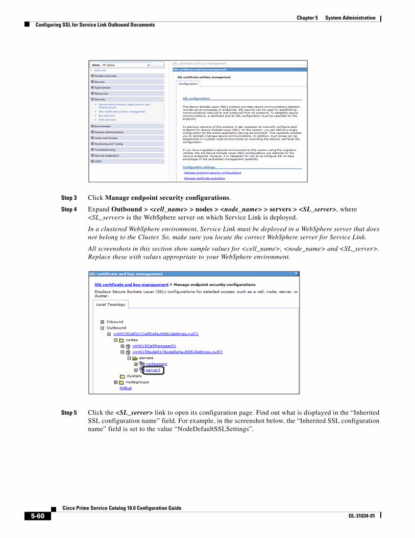
Chapter 5 System Administration Configuring SSL for Service Link Outbound Documents
Step 3 Click Manage endpoint security configurations.
Step 4 Expand Outbound > <cell_name> > nodes > <node_name> > servers > <SL_server>, where <SL_server> is the WebSphere server on which Service Link is deployed.
In a clustered WebSphere environment, Service Link must be deployed in a WebSphere server that does not belong to the Cluster. So, make sure you locate the correct WebSphere server for Service Link.
All screenshots in this section show sample values for <cell_name>, <node_name> and <SL_server>. Replace these with values appropriate to your WebSphere environment.
Step 5 Click the <SL_server> link to open its configuration page. Find out what is displayed in the “Inherited SSL configuration name” field. For example, in the screenshot below, the “Inherited SSL configuration name” field is set to the value “NodeDefaultSSLSettings”.
5-60Cisco Prime Service Catalog 10.0 Configuration Guide
OL-31034-01
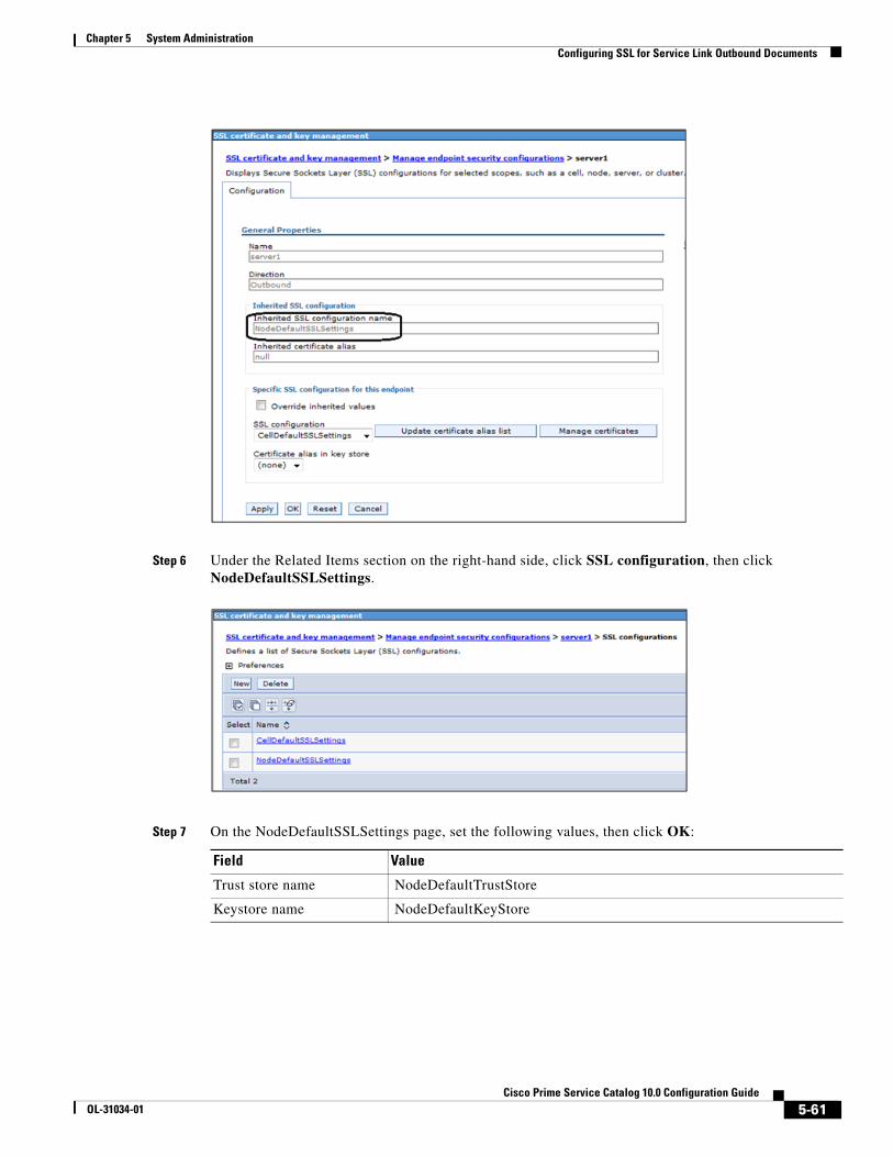
Chapter 5 System AdministrationConfiguring SSL for Service Link Outbound Documents
Step 6 Under the Related Items section on the right-hand side, click SSL configuration, then click NodeDefaultSSLSettings.
Step 7 On the NodeDefaultSSLSettings page, set the following values, then click OK:
Field Value
Trust store name NodeDefaultTrustStore
Keystore name NodeDefaultKeyStore
5-61Cisco Prime Service Catalog 10.0 Configuration Guide
OL-31034-01
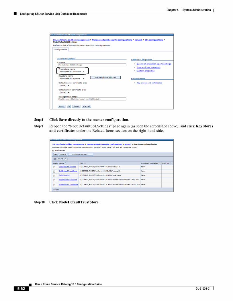
Chapter 5 System Administration Configuring SSL for Service Link Outbound Documents
Step 8 Click Save directly to the master configuration.
Step 9 Reopen the “NodeDefaultSSLSettings” page again (as seen the screenshot above), and click Key stores and certificates under the Related Items section on the right-hand side.
Step 10 Click NodeDefaultTrustStore.
5-62Cisco Prime Service Catalog 10.0 Configuration Guide
OL-31034-01

Chapter 5 System AdministrationConfiguring SSL for Service Link Outbound Documents
Step 11 Under the Additional Properties section on the right-hand side, click Signer certificates.
Step 12 Click Add.
Step 13 Enter the following values, then click OK:
Field Value
Alias A value for the signer certificate (that is, “extws”).
File name The path to the signer certificate file (that is, “C:\temp\extws.cer”).
Data type Choose the value “Base64-encoded ASCII data” in the drop-down list.
5-63Cisco Prime Service Catalog 10.0 Configuration Guide
OL-31034-01
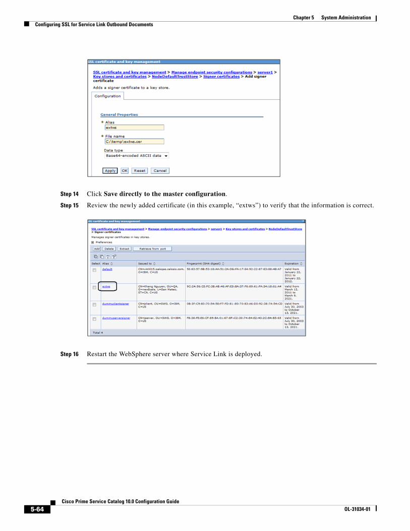
Chapter 5 System Administration Configuring SSL for Service Link Outbound Documents
Step 14 Click Save directly to the master configuration.
Step 15 Review the newly added certificate (in this example, “extws”) to verify that the information is correct.
Step 16 Restart the WebSphere server where Service Link is deployed.
5-64Cisco Prime Service Catalog 10.0 Configuration Guide
OL-31034-01
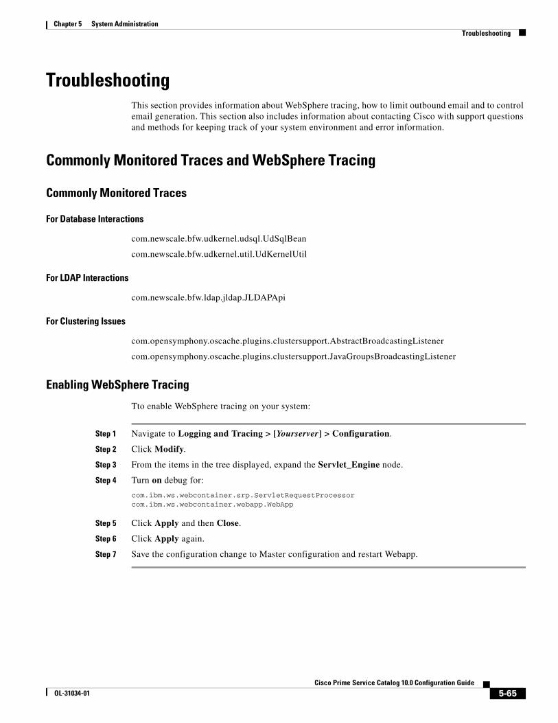
Chapter 5 System AdministrationTroubleshooting
TroubleshootingThis section provides information about WebSphere tracing, how to limit outbound email and to control email generation. This section also includes information about contacting Cisco with support questions and methods for keeping track of your system environment and error information.
Commonly Monitored Traces and WebSphere Tracing
Commonly Monitored Traces
For Database Interactions
com.newscale.bfw.udkernel.udsql.UdSqlBean
com.newscale.bfw.udkernel.util.UdKernelUtil
For LDAP Interactions
com.newscale.bfw.ldap.jldap.JLDAPApi
For Clustering Issues
com.opensymphony.oscache.plugins.clustersupport.AbstractBroadcastingListener
com.opensymphony.oscache.plugins.clustersupport.JavaGroupsBroadcastingListener
Enabling WebSphere Tracing
Tto enable WebSphere tracing on your system:
Step 1 Navigate to Logging and Tracing > [Yourserver] > Configuration.
Step 2 Click Modify.
Step 3 From the items in the tree displayed, expand the Servlet_Engine node.
Step 4 Turn on debug for:
com.ibm.ws.webcontainer.srp.ServletRequestProcessorcom.ibm.ws.webcontainer.webapp.WebApp
Step 5 Click Apply and then Close.
Step 6 Click Apply again.
Step 7 Save the configuration change to Master configuration and restart Webapp.
5-65Cisco Prime Service Catalog 10.0 Configuration Guide
OL-31034-01

Chapter 5 System Administration Troubleshooting
Limiting Outbound EmailYou may want to limit outbound email during service design testing or in nonproduction environments.
By limiting outbound email capabilities, you can limit or prevent the sending of email to actual performers or customers on whose behalf services are ordered.
Ways to Limit Outbound Email
Changing all email templates to have “fake addresses” in a development environment is not really an option. Firstly, it would be very time consuming. More important, much of the testing is invalidated when the template addresses are changed back—you would still need to ascertain that the correct people are receiving the appropriate emails.
If templates use only namespace variables and users in the nonproduction environment are refreshed via directory integration, you could change the LDAP mapping to give everyone the same email address or a similar fake address, for example:
User@<company>.com, or
reqcentertest@<company>.com
by using a mapping similar to:
expr:#cn#=(cannotmatch)?(neverthis):requestcenter@<company>.com
However, this approach also does not allow you to adequately test the accuracy of email delivery.
A more robust solution is to use a dedicated SMTP (email) server for the development instance and any other instances where emails should not be distributed outside the box. You can set up an SMTP server that routes ALL emails (whether fake or correct) to a standard mailbox (for example, [email protected]) for the development and test servers. This way, you do not have to change Request Center configuration in any way, and emails could be tested very easily. The project team just needs to be able to open that test mailbox.
This requires the customer be able to configure a separate test SMTP server that overrides the recipients to always forward to the test email box. Production would need to point to the production SMTP server, of course.
If you use any of these techniques, add the To/Cc addressees in the HTML body of the email templates surrounded by <!-- Comment --> tags so that testers may validate the namespace expression and other logic for these fields.
Controlling Email Generation
Service Catalog controls the outgoing email envelope and defaults to sending a single message to multiple recipients. The multiple-recipient messages are sent to the same SMTP server.
The alternative is to send single recipient emails has a minimal negative effect on CPU and network bandwidth usage. This is enabled via a setting in the newscale.properties file:
Email.One.Per.Recipient=true
Use this setting only to avoid SMTP server problems whereby the entire message is rejected if one recipient is invalid.
SMTP connections are tried Email.ServerDownCount=10 times and then paused for Email.RescheduleOffset (msec).
Full mailboxes, bounces or other delivery problems are retried based on the Email.RetryCount=4 setting.
5-66Cisco Prime Service Catalog 10.0 Configuration Guide
OL-31034-01

Chapter 5 System AdministrationTroubleshooting
Environment/Platform OverviewIt is useful to document the systems in your environment by using a matrix like the one provided in the “Sample Environment Matrix” section on page 5-75.
Cisco publishes a support matrix detailing the software on which each version of Service Catalog is certified. The Cisco Technical Assistance Center (TAC) will always have the most current version of this matrix, adjusted for point releases and Service Packs.
When to Call the Cisco Technical Assistance Center (TAC)It is a good idea to inform the Cisco Technical Assistance Center (TAC) before performing any system maintenance tasks that may affect:
• Server operating system patches/upgrades
• Database server patches/upgrades
• Service Catalog application server patches or upgrades – Validate the update is supported by Cisco first!
• LDAP Directory tree structure changes
• Single Sign-On system upgrades
Collecting Troubleshooting Information
Site Debugging
If an “Our Apologies” exception occurs, you may turn on “Debug” via the Debugging option of Administration module Settings.
Debugging adds the URL of the current page at the bottom of the page. Clicking on the URL provides links to additional information which may be helpful to Cisco support personnel.
5-67Cisco Prime Service Catalog 10.0 Configuration Guide
OL-31034-01

Chapter 5 System Administration Troubleshooting
When you are finished, do not forget to turn debugging off, as it may confuse end-users. It also adversely affects performance.
The application log is a key troubleshooting mechanism. Looking in this log for “Exception” (from the bottom up) often reveals the applicable error message.
In a clustered environment, it is often useful to browse the log files from all the machines in the cluster for the period in question.
Service Link Log Files
Logs for the Service Link server show the details of all Service Link transactions for that day. It is often useful to correlate that file to the Request Center server log when troubleshooting issues that have to do with the interaction between the Business Engine and Service Link.
Performance
Gather performance information from the log and native_stderr.log files.
Service Design and Platform Dependence
Problems that arise during service design may be related to incorrect service configuration. Problems that occur only in a production environment may be data-dependent or platform-dependent. In some cases, the Cisco Technical Assistance Center (TAC) may ask for a dump of the database to be sent, where it can be installed in a testing lab that can closely emulate the environment where the error occurred. Customers should have logins and credentials that allow them to upload the database to the Cisco support site for investigation.
How to Reach Product Support
Contact the Cisco Technical Assistance Center (TAC):
• For Solutions
– Get access to the documentation library
– Learn about upgrades and patches
– Learn answers to Common Issues
• About Cases
– Log new cases
– Check status of cases
– Read/Update case investigation comments
– Attach logs/files
5-68Cisco Prime Service Catalog 10.0 Configuration Guide
OL-31034-01
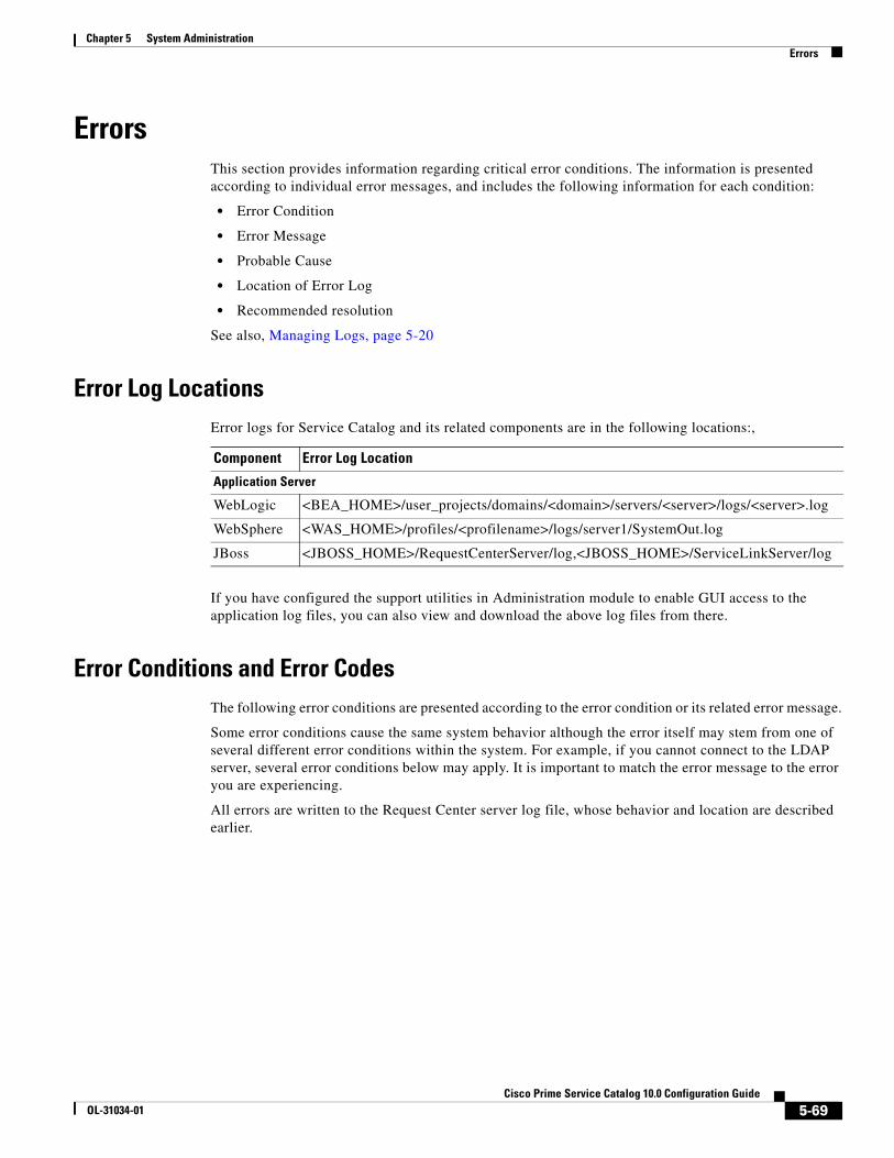
Chapter 5 System AdministrationErrors
ErrorsThis section provides information regarding critical error conditions. The information is presented according to individual error messages, and includes the following information for each condition:
• Error Condition
• Error Message
• Probable Cause
• Location of Error Log
• Recommended resolution
See also, Managing Logs, page 5-20
Error Log LocationsError logs for Service Catalog and its related components are in the following locations:,
If you have configured the support utilities in Administration module to enable GUI access to the application log files, you can also view and download the above log files from there.
Error Conditions and Error CodesThe following error conditions are presented according to the error condition or its related error message.
Some error conditions cause the same system behavior although the error itself may stem from one of several different error conditions within the system. For example, if you cannot connect to the LDAP server, several error conditions below may apply. It is important to match the error message to the error you are experiencing.
All errors are written to the Request Center server log file, whose behavior and location are described earlier.
Component Error Log Location
Application Server
WebLogic <BEA_HOME>/user_projects/domains/<domain>/servers/<server>/logs/<server>.log
WebSphere <WAS_HOME>/profiles/<profilename>/logs/server1/SystemOut.log
JBoss <JBOSS_HOME>/RequestCenterServer/log,<JBOSS_HOME>/ServiceLinkServer/log
5-69Cisco Prime Service Catalog 10.0 Configuration Guide
OL-31034-01

Chapter 5 System Administration Errors
Failure to perform Asynchronous Submit/Authorization
Application Server Loses Connection to the Database
Failure to Connect to the LDAP Server – Incorrect Port
Error Condition Service Catalog is not able to instantiate a task plan asynchronously, after the request submission or the last authorization/review in the service.
Error Message Requisition xxx [Task “<name of task here>”]: We’re sorry but his approval/review cannot be completed at this time because the Request Center queue that processes these tasks is temporarily unavailable. Please try again later or contact your Request Center system administrator.
Resolution Verify that the JMS queue which serves the asynchronous submit/last authorization process is available for receiving messages.
Error Condition Application server lost the connection to the database.
Error Message ERROR [com.celosis.logger.FatalerrorChannel] (8000)SQLException in getConnection:Could not create connection; - nested throwable: (java.sql.SQLException: [newScale][SQLServer JDBC Driver]Error establishing socket. Connection refused: connect); - nested throwable: (org.jboss.resource.JBossResourceException: Could not create connection; - nested throwable: (java.sql.SQLException: [newScale][SQLServer JDBC Driver]Error establishing socket. Connection refused: connect)) Code: 0 State: null.
Resolution Check the RequestCenter database. If the RequestCenter database is not running, start it. Once the database is up, the application server will automatically connect to it.
Error Code LDAPException 91.
Error Condition Cannot connect to the LDAP server. Most likely the LDAP server is down or you have an incorrect port number.
Error Message ERROR [com.newscale.bfw.ldap.jldap.JLDAPNonSSLConnection] LDAPException in NON-SSL Connection:
LDAPException: Unable to connect to server <hostname>:<port> (91) Connect Error
java.net.ConnectException: Connection refused: connect
Resolution Check to see if the LDAP server is running. If not, start the LDAP server.
Check the LDAP System Connection Parameters on Administration > Directories. Verify that the Connection Port value is correct.
You do not need to restart the Request Center application.
5-70Cisco Prime Service Catalog 10.0 Configuration Guide
OL-31034-01

Chapter 5 System AdministrationErrors
Failure to Connect to the LDAP Server – Incorrect Hostname
Failure to Connect to the LDAP Server – LDAPException 32
Failure to Connect to the LDAP Server – LDAPException 49
Failure to Connect to the LDAP Server
Error Code LDAPException 91
Error Condition Cannot connect to the LDAP server. Most likely incorrect hostname.
Error Message ERROR [com.newscale.bfw.ldap.jldap.JLDAPNonSSLConnection] LDAPException in NON-SSL Connection:
LDAPException: Unable to connect to server <hostname>:<port> (91) Connect Error
java.net.UnknownHostException: <hostname>
Resolution Check the LDAP System Connection Parameters on Administration > Directories. Verify that the LDAP Host value is correct.
Error Code LDAPException 32
Error Condition Cannot connect to the LDAP server. Most likely incorrect authenticated user id.
Error Message ERROR [com.newscale.bfw.ldap.jldap.JLDAPSimpleAuth] LDAPException in Simple Auth:
LDAPException: No Such Object (32) No Such Object
LDAPException: Matched DN:
Resolution Check the LDAP System Authentication Parameters on Administration > Directories. Verify that the BindDN value is correct.
Error Code LDAPException 49
Error Condition Cannot connect to the LDAP server. Most likely incorrect authenticated password.
Error Message ERROR [com.newscale.bfw.ldap.jldap.JLDAPSimpleAuth] LDAPException in Simple Auth:
LDAPException: Invalid Credentials (49) Invalid Credentials
Resolution Check the LDAP System Authentication Parameters on Administration > Directories. The Password field is encrypted and thus you can not verify its existing value. Just enter a correct value for the Password, and click Update.
Error Condition Cannot connect to the LDAP server.
Error Message FATAL [LDAPBase] LDAP instance cannot be created netscape.ldap.LDAPException: no host for connection (89)
Resolution Check to see if the LDAP server is running. If not, start the LDAP server.
You do not need to restart the Request Center application server.
5-71Cisco Prime Service Catalog 10.0 Configuration Guide
OL-31034-01

Chapter 5 System Administration Errors
Failure to Connect to the LDAP Server
Failure to Authenticate with the LDAP Server
Attribute Name is Mapped Incorrectly
User Base DN in LDAP Server is Missing
Error Condition Cannot connect to the LDAP server.
Error Message ERROR [com.newscale.bfw.ldap.LDAPQuery] LDAP netscape.ldap.LDAPException: failed to connect to server ldap://<hostname>:<port> (91)
Resolution Check to see if the LDAP server is running. If not, start the LDAP server.
You do not need to restart the Request Center application server.
Error Condition Fail to authenticate with the LDAP server.
Error Message ERROR [com.newscale.comps.user.dao.LDAPUserDataSource] Single Person search failure, exception thrown: null
com.newscale.bfw.dataaccess.DataAccessException
Resolution Check the Data Source Configuration on the Administration > Directories page.
Verify the following parameters and correct if necessary:
• BindDN
• Password
• User BaseDN
You do not need to restart the Request Center application server.
Error Condition One of the required attributes is incorrectly mapped. Thus the person cannot be found in the LDAP server.
Error Message ERROR [com.newscale.bfw.ldap.LDAPQuery] LDAP java.lang.RuntimeException: Required LDAP attribute <attribute_name> is missing from the LDAP system.
Resolution Correct the attribute name in the Directory Data Mapping. You do not need to restart the Request Center application server.
Error Code LDAPException 32
Error Condition Cannot find the User Base DN in LDAP server.
Error Message ERROR [com.newscale.bfw.ldap.jldap.JLDAPApi] Referral Exception during Result Set iteration:
LDAPException: No Such Object (32) No Such Object
Resolution Check the LDAP System Authentication Parameters on the Administration > Directories page. Verify that the LDAP User BaseDN value is correct.
5-72Cisco Prime Service Catalog 10.0 Configuration Guide
OL-31034-01

Chapter 5 System AdministrationErrors
Failure to Connect to the LDAP Server in SSL Mode
Failure to Connect to the LDAP Server in SSL Mode
“Common OU for new users” Configuration Value is Missing
Error Condition (For SSL connection only) Cannot connect to the LDAP Server in SSL mode, because the SSL certificate keystore has not been created.
Error Message DEBUG [com.newscale.bfw.ldap.util.LDAPConfUtil] The LDAP configuration file “config/<LDAP_System>_TrustCertDB.keystore” does not exist.
Resolution Add the appropriate server certificate for the LDAP System on the Administration > Directories page.
Error Condition (For SSL connection only) Cannot connect to the LDAP Server in SSL mode, because the server certificate in the keystore is NOT correct.
Error Message ERROR [com.newscale.bfw.ldap.jldap.JLDAPSimpleAuth] LDAPException in Simple Auth:
LDAPException: I/O Exception on host <hostname>, port <port number> (91) Connect Error
javax.net.ssl.SSLException: Connection has been shutdown: javax.net.ssl.SSLHandshakeException: sun.security.validator.ValidatorException: No trusted certificate found
Resolution The certificate keystore may already exist, but does not contain the correct certificate used with this LDAP Server. Obtain the correct certificate used for the LDAP server, and add it for the same LDAP System on the Administration > Site Configuration page.
Error Condition The “Common OU for new users” configuration value is either missing or does not exist in RequestCenter database.
Error Message ERROR [com.newscale.comps.user.dao.LDAPUserDataSource] Error getting Person from Ldap
java.lang.NullPointerException
at com.newscale.comps.user.dao.LDAPUserDataSource.transferOrgUnitVOToBO(LDAPUserDataSource.java:676)
Resolution Check the LDAP System Lookup Configuration on the Administration > Site Configuration page. Choose a correct value for the “Common OU for new users” field.
5-73Cisco Prime Service Catalog 10.0 Configuration Guide
OL-31034-01

Chapter 5 System Administration Errors
User Cannot be Found in the LDAP Server
Failure to Connect to a Referral LDAP System
Failure to Connect to the External Data Dictionary Database
Lost Connection to the Database
Error Condition The <attribute_name> is incorrectly mapped. Thus, the person cannot be found in the LDAP server.
Error Message WARN [com.newscale.bfw.ldap.jldap.JLDAPApi] Required LDAP attribute <attribute_name> is missing from the LDAP system, for DN : …
Resolution Correct the attribute name on the Directory Mapping page, for the appropriate LDAP System.
Error Condition Cannot connect to one of the Referral LDAP Systems.
(The config flag SkipErrorOnLDAPSystem=true; thus, Request Center system ignores this error.)
Error Message WARN [com.newscale.bfw.ldap.jldap.JLDAPApi] Referral Exception during Result Set iteration:
LDAPReferralException: Search result reference received, and referral following is off (10)
Resolution Check to see if the Referral LDAP server is running.
Verify the Authentication and Connection for the Referral LDAP System.
Error Condition Cannot connect to the External Data Dictionary Database.
Error Message ERROR [STDERR] SQLException while attempting to connect: java.sql.SQLException: [Macromedia][SQLServer JDBC Driver]Error establishing socket. Connection refused: connect.
Resolution Check the External Data Dictionary database. If the External Data Dictionary database is not running, start it.
You do not need to restart the Request Center application.
Error Condition Lost the connection to the database.
Error Message ERROR [com.celosis.logger.FatalerrorChannel] (8000)SQLException in getConnection: Could not create connection; - nested throwable: (java.sql.SQLException: [newScale ][SQLServer JDBC Driver]Error establishing socket. Connection refused: connect)
Resolution Check the database. If the database is not running, start it. Once the database is up, the application server will automatically connect to it.
5-74Cisco Prime Service Catalog 10.0 Configuration Guide
OL-31034-01
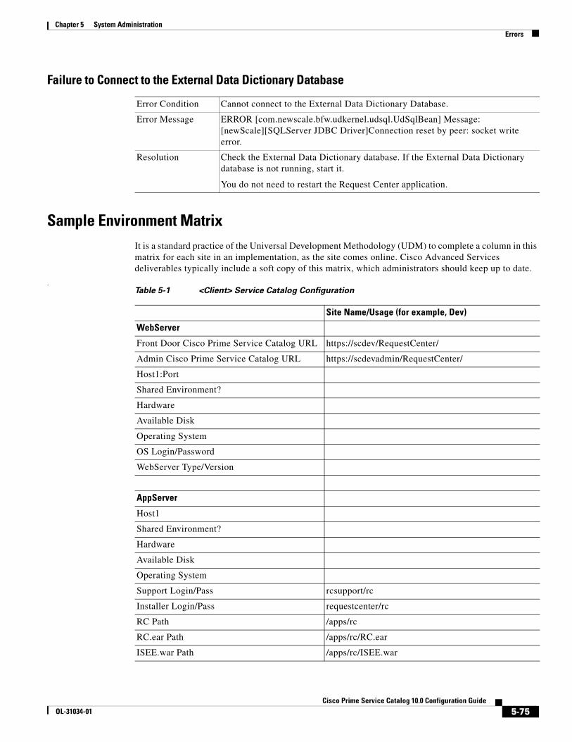
Chapter 5 System AdministrationErrors
Failure to Connect to the External Data Dictionary Database
Sample Environment MatrixIt is a standard practice of the Universal Development Methodology (UDM) to complete a column in this matrix for each site in an implementation, as the site comes online. Cisco Advanced Services deliverables typically include a soft copy of this matrix, which administrators should keep up to date.
.
Error Condition Cannot connect to the External Data Dictionary Database.
Error Message ERROR [com.newscale.bfw.udkernel.udsql.UdSqlBean] Message: [newScale][SQLServer JDBC Driver]Connection reset by peer: socket write error.
Resolution Check the External Data Dictionary database. If the External Data Dictionary database is not running, start it.
You do not need to restart the Request Center application.
Table 5-1 <Client> Service Catalog Configuration
Site Name/Usage (for example, Dev)
WebServer
Front Door Cisco Prime Service Catalog URL https://scdev/RequestCenter/
Admin Cisco Prime Service Catalog URL https://scdevadmin/RequestCenter/
Host1:Port
Shared Environment?
Hardware
Available Disk
Operating System
OS Login/Password
WebServer Type/Version
AppServer
Host1
Shared Environment?
Hardware
Available Disk
Operating System
Support Login/Pass rcsupport/rc
Installer Login/Pass requestcenter/rc
RC Path /apps/rc
RC.ear Path /apps/rc/RC.ear
ISEE.war Path /apps/rc/ISEE.war
5-75Cisco Prime Service Catalog 10.0 Configuration Guide
OL-31034-01
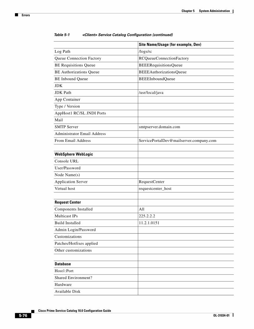
Chapter 5 System Administration Errors
Log Path /logs/rc
Queue Connection Factory RCQueueConnectionFactory
BE Requisitions Queue BEEERequisitionsQueue
BE Authorizations Queue BEEEAuthorizationsQueue
BE Inbound Queue BEEEInboundQueue
JDK
JDK Path /usr/local/java
App Container
Type / Version
AppHost1 RC/SL JNDI Ports
SMTP Server smtpserver.domain.com
Administrator Email Address
From Email Address [email protected]
WebSphere WebLogic
Console URL
User/Password
Node Name(s)
Application Server RequestCenter
Virtual host requestcenter_host
Request Center
Components Installed All
Multicast IPs 225.2.2.2
Build Installed 11.2.1.0151
Admin Login/Password
Customizations
Patches/Hotfixes applied
Other customizations
Database
Host1:Port
Shared Environment?
Hardware
Available Disk
Table 5-1 <Client> Service Catalog Configuration (continued)
Site Name/Usage (for example, Dev)
5-76Cisco Prime Service Catalog 10.0 Configuration Guide
OL-31034-01
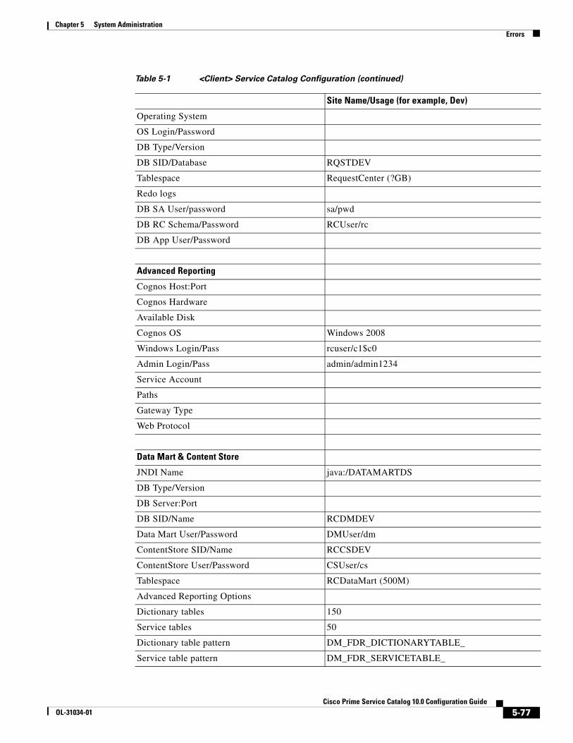
Chapter 5 System AdministrationErrors
Operating System
OS Login/Password
DB Type/Version
DB SID/Database RQSTDEV
Tablespace RequestCenter (?GB)
Redo logs
DB SA User/password sa/pwd
DB RC Schema/Password RCUser/rc
DB App User/Password
Advanced Reporting
Cognos Host:Port
Cognos Hardware
Available Disk
Cognos OS Windows 2008
Windows Login/Pass rcuser/c1$c0
Admin Login/Pass admin/admin1234
Service Account
Paths
Gateway Type
Web Protocol
Data Mart & Content Store
JNDI Name java:/DATAMARTDS
DB Type/Version
DB Server:Port
DB SID/Name RCDMDEV
Data Mart User/Password DMUser/dm
ContentStore SID/Name RCCSDEV
ContentStore User/Password CSUser/cs
Tablespace RCDataMart (500M)
Advanced Reporting Options
Dictionary tables 150
Service tables 50
Dictionary table pattern DM_FDR_DICTIONARYTABLE_
Service table pattern DM_FDR_SERVICETABLE_
Table 5-1 <Client> Service Catalog Configuration (continued)
Site Name/Usage (for example, Dev)
5-77Cisco Prime Service Catalog 10.0 Configuration Guide
OL-31034-01
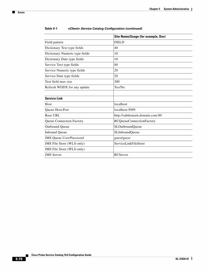
Chapter 5 System Administration Errors
Field pattern FIELD
Dictionary Text type fields 40
Dictionary Numeric type fields 10
Dictionary Date type fields 10
Service Text type fields 80
Service Numeric type fields 20
Service Date type fields 20
Text field max size 200
Refresh WDDX for any update Yes/No
Service Link
Host localhost
Queue Host:Port localhost:5099
Base URL http://subdomain.domain.com:80
Queue Connection Factory RCQueueConnectionFactory
Outbound Queue SLOutboundQueue
Inbound Queue SLInboundQueue
JMS Queue User/Password guest/guest
JMS File Store (WLS-only) ServiceLinkFileStore
JMS File Store (WLS-only)
JMS Server RCServer
Table 5-1 <Client> Service Catalog Configuration (continued)
Site Name/Usage (for example, Dev)
5-78Cisco Prime Service Catalog 10.0 Configuration Guide
OL-31034-01
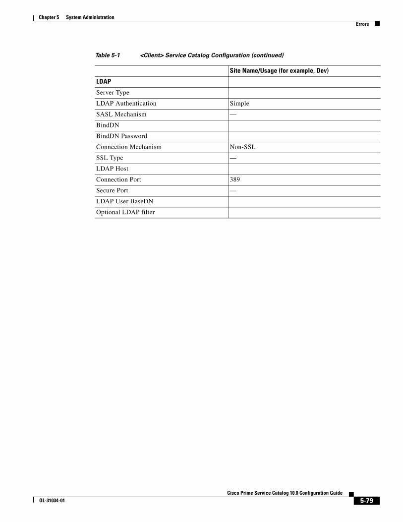
Chapter 5 System AdministrationErrors
LDAP
Server Type
LDAP Authentication Simple
SASL Mechanism —
BindDN
BindDN Password
Connection Mechanism Non-SSL
SSL Type —
LDAP Host
Connection Port 389
Secure Port —
LDAP User BaseDN
Optional LDAP filter
Table 5-1 <Client> Service Catalog Configuration (continued)
Site Name/Usage (for example, Dev)
5-79Cisco Prime Service Catalog 10.0 Configuration Guide
OL-31034-01

Chapter 5 System Administration Errors
5-80Cisco Prime Service Catalog 10.0 Configuration Guide
OL-31034-01

CiOL-31034-01
I N D E X
A
Active Form Rules 5-33
Administration 1-5
Administration, Settings Tab 3-10
Administration Module 3-1
Administrative Rights 1-5
Anyone 1-5
Anyone Role 1-35
Application Server
Installing the Keystore 5-39 to 5-56
Tuning 5-3
Asynchronous Submission 3-11
Messages 3-23
Authorizations 1-11, 3-2 to 3-7
Defined 3-2
Enabling 3-2
Reviews 3-2
Site-Wide 3-2
Authorizations Portlet 3-17, 3-18
B
Backup Methodology 5-3
Browser Cache Setting 3-12
Business Engine 3-7
Caching 5-25
Purging Temporary Data 3-30
Business Goals and Initiatives List 3-10
Business Units 1-7
C
Calendar
Configuring for a Person 1-27
Queue 1-21
User 2-2
Capabilities 1-39 to 1-47
Administration 1-45
Assigning Role Capabilities 1-41
My Services 1-41
Organization Designer 1-44
Reporting 1-43
Service Designer 1-42
Service Link 1-43
Service Manager 1-44
Cascading Style Sheets 3-23, 4-1
Catalog Deployer 5-36
User Counter Reset 3-23
Certificate File
Creating 5-38
Installing 5-39 to 5-56
Cisco Technical Assistance Center (TAC) 5-67, 5-68
Cognos Server, Restarting 5-2
Columns, adjusting 3-32
Common Settings 3-13
Common Tasks Pane 1-2
Common Tasks Portlet 3-19
Configuration Files 5-19
Content Pane 1-2
Cost Drivers List 3-9
Custom Code 5-32
Custom Header Footer 4-18
Enabling 3-25, 4-4
IN-1sco Prime Service Catalog 10.0 Configuration Guide

Index
Customizations 3-11
Customized Installation 5-33
Customizing Sites 3-10, 4-1
Custom Mappings 5-32
Custom Roles ?? to 1-51
Samples 1-52 to 1-54
Custom Styles 3-21, 4-1 to 4-11
Browser Cache Setting 4-5
Built-In Modules 4-2, 4-11
Buttons 4-8
Defining 3-24, 4-3
Enabling 3-13, 3-25, 4-4
Navigation Bars 4-8
Page Headers 4-7
Preserving 4-9
Recommended Practices 4-17
Service Forms 4-8
User-Defined Modules 4-16
User-Defined Portals 4-3
D
Database
Copying 5-36
Security 5-25
Tuning 5-5
Data Security 5-25
Data Source Registry 3-25
Data Sources 5-22
Date Formats 2-2
Debugging Settings 3-23
Default Service Manager Status (for task search) 2-2
Default Service Manager View 2-2
Destination Folder 3-27
Directory Integration 1-6, 3-2, 5-31
Enabling 3-13, 3-14
Directory Mappings 5-31
IN-2Cisco Prime Service Catalog 10.0 Configuration Guide
E
Controlling Generation 5-66
Limiting Outbound 5-66
Email Templates 3-8, 3-9
Configuring 3-9
Using Namespaces 3-9
Viewing 3-8
Encryption 3-13
Entities 1-4
Administration 1-5
Copying 1-4
Creating 1-4
Deactivating 1-5
Deleting 1-5
Relationships 1-6
System-defined 1-6
Entity Homes 3-22
Environment Matrix, Sample 5-75
Error Conditions and Error Codes 5-69 to 5-75
Error Log Locations 5-69
Escalation Manager 3-7, 5-28
Escalations 3-7
Extensions 1-26
External Dictionaries, Backing Tables 5-23
F
Form Data Viewer 3-31
Form Monitor 3-18
Show/Hide 3-17
Functional Positions 1-10, 1-30
Creating New 1-31
Deleting 1-32
Modifying 1-31
OL-31034-01
Index
G
Groups 1-14 to 1-18
Configuring 1-14
Defined 1-14
Members 1-15
Roles 1-16
Using in Service Design 1-16
H
Headers and Footers, Custom 4-18
Home Organizational Unit (OU) 1-7
I
Installation
Custom 5-33
Integration Types 5-30
Interactive Service Forms (ISF) 5-30
Defined 5-33
ISF. See Interactive Service Forms (ISF).
K
Keystore
Creating 5-38
Installing 5-39 to 5-56
L
Language, Preferred 2-2
Language List 3-10
Last Approval 3-11
Limiting Outbound Email 5-66
Lists 3-9
Business Goals and Initiatives 3-10
Cost Drivers 3-9
OL-31034-01
Language 3-10
Objectives 3-9
Offering Attributes 3-10
Unit of Measure 3-10
Log Files
JBoss 5-22
Managing 5-20
Performance 5-68
Service Link 5-68
View and Download 3-29
WebLogic 5-22
WebSphere 5-21
Log Folder. See Server Log Folder.
Login Module 2-2
Login Settings 3-13
Logs and Properties Tab 3-26
Adjusting the Pane Displays 3-32
M
Manage Email Templates 3-8
Manage Service Team, Permissions 1-11
Modules, Customizing 3-24
Monitored Traces 5-65
Multicast Settings 5-29
My Services
Portlets 3-19
Settings 3-16
N
Navigation Bar, Organization Designer 1-2
Navigation Pane 1-2
Notifications 3-8
O
Objectives List 3-9
IN-3Cisco Prime Service Catalog 10.0 Configuration Guide
Index
Offering Attributes List 3-10
Oracle 5-21
Order on Behalf Permission 1-11
Organizational Unit (OU) 1-7
Configuring 1-8
Create a Person/OU Relationship. 1-9
Create a Queue/OU Relationship 1-9
Deactivating 1-8
General Page 1-8
Hierarchies 1-8
Home Organizational Unit (OU) 1-7
Maintaining 1-7
Roles 1-12
Organization Designer
Accessing 1-1
Administration 1-13
Component-Specific Search 1-3
Home Page 1-2
Home Page Search 1-2
Navigation Bar 1-2
Organization Summary Pane 1-2
OU. See Organization Unit (OU).
P
People 1-22 to 1-29
Assign to an Organizational Unit 1-9
Calendar 1-27
Configuring 1-23
Creating New 1-22
Deactivating 1-29
Deleting 1-29
Extensions 1-26
Performance Logs 5-68
Permissions 1-11
Assigning for an Organizational Unit 1-11
Assigning to a Person 1-28
Manage Service Team 1-11
Order on Behalf 1-11
IN-4Cisco Prime Service Catalog 10.0 Configuration Guide
Queues 1-21
Portlet
Authorizations 3-17, 3-18
Common Tasks 3-19
My Services 3-19
Requisitions 3-19
Service Items 3-17, 3-18
Preferences
User 2-2
Preferred Language 2-2
Profile 1-27, 2-1
Calendar 2-2
Information 2-1
Preferences 2-2
Preferred Language 2-2
Property Files
View and Download 3-29
Purge
Business Engine 3-30
Requisitions 3-30, 5-12 to 5-15
Service Link Messages 3-30
Sevice Link Message Purge Utility 5-17 to 5-18
Workflow Purge Utility 5-15 to 5-17
Purge Utilities 3-30
Q
Queues 1-19 to 1-22
Assign a Queue to an OU. 1-9
Assigning Service Teams to a Queue 1-20
Calendar 1-21
Configuring 1-19
Contact 1-20
Permissions 1-21
R
RBAC. See Role-Based Access Control (RBAC).
OL-31034-01

Index
Relationship Manager 5-28
Reporting and Advanced Reporting, Scripts 5-26
Requisition Purge 5-12 to 5-15
Requisitions
Purging 3-30
Requisitions Portlet 3-19
Reviews, Defined 3-2
Role-Based Access Control (RBAC) 1-32
Roles 1-12, 1-32
Anyone 1-35
Assigning to a Person 1-29
Configuring 1-36
Creating a Role/Member association 1-37
Custom ?? to 1-51
Hierarchy 1-32
Sample Custom Roles 1-52 to 1-54
Searching 1-36
Shown Inherited Roles 1-13
Site Administrator 1-35
System-Defined 1-32, 1-33
S
Scripts, Reporting and Advanced Reporting 5-26
Searching 1-2
Component-Specific Search 1-3
Home Page Search 1-2
Roles 1-36
Security 5-25
Application 5-26
Server Log Folder 3-27
Service Export, Configuring 5-23
Service Items Portlet 3-17, 3-18
Service Link 5-33
Configuring SSL for Service Link Inbound Documents 5-37 to 5-56
Configuring SSL for Service Link Outbound Documents 5-56 to 5-64
Message Purge Utility 5-17 to 5-18
OL-31034-01
Purging Messages 3-30
Recreating Missing Service Link Messages 5-67
Setting 3-21
Service Link Adapters
Installing Additional 5-37
Service Manager 5-28
Settings 3-20
Service Portal
Managing 5-19
Service Teams 1-7
Settings 3-21
Common 3-13
Debugging 3-23
Login 3-13
Multicast 5-29
My Services 3-16
Service Link 3-21
Service Manager 3-20
Site 3-10
Web Services 3-21
Show Inherited Roles Option 1-13
Single Sign-On 3-12, 3-14, 5-32
Site Administrator Role 1-35
Site Configuration Settings 5-24
Site Debugging 5-67
Site Settings 3-10
Site-Wide Authorizations 3-2
SSL, Configuring 5-39 to 5-56
Startup and Shutdown Procedures 5-2
Subgroups, Adding or Removing 1-15
Support Utilities 3-26 to 3-33
System-Defined Roles 1-32, 1-33
T
TAC. See Cisco Technical Assisatance Center.
Time Format 2-3
Troubleshooting 5-65 to 5-68
IN-5Cisco Prime Service Catalog 10.0 Configuration Guide

Index
U
Unit of Measure List 3-10
User Profile. See Profile.
Use Support Utilities 3-26
Utilities 3-26 to 3-33
V
Version History 3-31
W
Web Services Setting 3-21
WebSphere Tracing, Enabling 5-65
Workflow Purge Utility 5-15 to 5-17
IN-6Cisco Prime Service Catalog 10.0 Configuration Guide
OL-31034-01