
Cisco labs practical3
15
1 - 6 CCNA 2: Routers and Routing Basics v 3.1 - Lab 6.1.6 Copyright 2003, Cisco Systems, Inc. Lab 6.1.6 Configuring Static Routes Objective • Configure static routes between routers to allow data transfer between routers without the use of dynamic routing protocols. Background/Preparation Setup a network similar to the one in the diagram. Any router that meets the interface requirements may be used. Possible routers include 800, 1600, 1700, 2500, 2600 routers, or a combination. Refer to the chart at the end of the lab to correctly identify the interface identifiers to be used based on the equipment in the lab. The configuration output used in this lab is produced from 1721 series routers. Any other router used may produce slightly different output. The following steps are intended to be executed on each router unless specifically instructed otherwise. Start a HyperTerminal session as performed in the Establishing a HyperTerminal session lab. Note: Go to the erase and reload instructions at the end of this lab. Perform those steps on all routers in this lab assignment before continuing. Step 1 Configure both routers a. Enter the global configuration mode and configure the hostname as shown in the chart. Then configure the console, virtual terminal, and enable passwords. If there are any difficulties, refer to
Transcript of Cisco labs practical3

1 - 6 CCNA 2: Routers and Routing Basics v 3.1 - Lab 6.1.6 Copyright 2003, Cisco Systems, Inc.
Lab 6.1.6 Configuring Static Routes
Objective • Configure static routes between routers to allow data transfer between routers without the use of
dynamic routing protocols.
Background/Preparation Setup a network similar to the one in the diagram. Any router that meets the interface requirements may be used. Possible routers include 800, 1600, 1700, 2500, 2600 routers, or a combination. Refer to the chart at the end of the lab to correctly identify the interface identifiers to be used based on the equipment in the lab. The configuration output used in this lab is produced from 1721 series routers. Any other router used may produce slightly different output. The following steps are intended to be executed on each router unless specifically instructed otherwise.
Start a HyperTerminal session as performed in the Establishing a HyperTerminal session lab.
Note: Go to the erase and reload instructions at the end of this lab. Perform those steps on all routers in this lab assignment before continuing.
Step 1 Configure both routers a. Enter the global configuration mode and configure the hostname as shown in the chart. Then
configure the console, virtual terminal, and enable passwords. If there are any difficulties, refer to

2 - 6 CCNA 2: Routers and Routing Basics v 3.1 - Lab 6.1.6 Copyright 2003, Cisco Systems, Inc.
the Configuring router passwords lab. Configure interfaces and IP host tables. If there are any difficulties, refer to the Configuring Host Tables lab. Do not configure a routing protocol.
Step 2 Configure the workstations Configure the workstations with the proper IP address, subnet mask, and default gateway.
a. The configuration for the host connected to the GAD Router is:
IP Address 192.168.14.2
IP subnet mask 255.255.255.0
Default gateway 192.168.14.1
b. The configuration for the host connected to the BHM Router is:
IP Address 192.168.16.2
IP subnet mask 255.255.255.0
Default gateway 192.168.16.1
c. Check connectivity between the workstations using ping. From the workstation attached to the GAD router, ping the workstation attached to the BHM router. C:\>ping 192.168.16.2 Pinging 192.168.16.2 with 32 bytes of data: Request timed out. Request timed out. Request timed out. Request timed out. Ping statistics for 192.168.16.2: Packets: Sent = 4, Received = 0, Lost = 4 (100% loss), Approximate round trip times in milli-seconds: Minimum = 0ms, Maximum = 0ms, Average = 0ms
d. Was the ping successful? __________________________________________________
e. Why did the ping fail? ______________________________________________________
Step 3 Check interface status a. Check the interfaces on both routers with the command show ip interface brief.
b. Are all the necessary interfaces up? ____________________________________________
Step 4 Check the routing table entries a. Using the command show ip route, view the IP routing table for GAD.
GAD>show ip route output eliminated Gateway of last resort is not set C 192.168.14.0/24 is directly connected, FastEthernet0 C 192.168.15.0/24 is directly connected, Serial0

3 - 6 CCNA 2: Routers and Routing Basics v 3.1 - Lab 6.1.6 Copyright 2003, Cisco Systems, Inc.
b. Use the command show ip route, view the IP routing table for BHM.
BHM>show ip route
Output eliminated.
Gateway of last resort is not set C 192.168.15.0/24 is directly connected, Serial0 C 192.168.16.0/24 is directly connected, FastEthernet0
c. Are all of the routes needed in the routing tables? __________________________________
d. "Based on the output from the show ip route command on the GAD and BHM routers, can a host on network 192.168.16.0 connect to a host on network 192.168.14.0?"___________________
If a route is not in the routers to which the host is connected, the host cannot reach the destination host.
Step 5 Adding static routes a. How can this situation be changed so that the hosts can ping each other?
Add static routes to each router or run a routing protocol.
b. In global configuration mode, add a static route on Router1 to network 192.168.16.0 and on Router2 to network 192.168.14.0. GAD(config)#ip route 192.168.16.0 255.255.255.0 192.168.15.2 BHM(config)#ip route 192.168.14.0 255.255.255.0 192.168.15.1
c. Why is a static route needed on both routers? ___________________________________
Step 6 Verify the new routes a. Use the command show ip route, view the IP routing table for GAD.
GAD>show ip route output eliminated Gateway of last resort is not set C 192.168.14.0/24 is directly connected, FastEthernet0 C 192.168.15.0/24 is directly connected, Serial0 S 192.168.16.0/24 [1/0] via 192.168.15.2
b. Using the command show ip route, view the IP routing table for BHM.
BHM>show ip route
Output eliminated.
Gateway of last resort is not set S 192.168.14.0/24 [1/0] via 192.168.15.1 C 192.168.15.0/24 is directly connected, Serial0 C 192.168.16.0/24 is directly connected, FastEthernet0

4 - 6 CCNA 2: Routers and Routing Basics v 3.1 - Lab 6.1.6 Copyright 2003, Cisco Systems, Inc.
c. Are all of the routes needed in the routing tables? __________________________________
d. Can a host on subnet 192.168.16.0 see a host on network 192.168.14.0? _________________
Step 7 ping host to host again a. Check connectivity between the workstations using ping. From the workstation attached to the
GAD router, ping the workstation attached to the BHM router. C:\>ping 192.168.16.2 Pinging 192.168.16.2 with 32 bytes of data: Reply from 192.168.16.2: bytes=32 time=20ms TTL=254 Reply from 192.168.16.2: bytes=32 time=20ms TTL=254 Reply from 192.168.16.2: bytes=32 time=20ms TTL=254 Reply from 192.168.16.2: bytes=32 time=20ms TTL=254 Ping statistics for 192.168.16.2: Packets: Sent = 4, Received = 4, Lost = 0 (0% loss), Approximate round trip times in milli-seconds: Minimum = 20ms, Maximum = 20ms, Average = 20ms
b. If the ping was not successful, check routing table to make sure static routes are entered
correctly.
Upon completion of the previous steps, logoff by typing exit. Turn the router off.
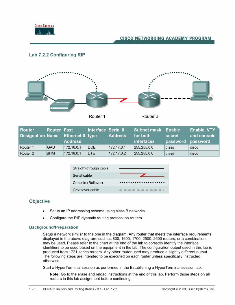
Lab 7.2.2 Configuring RIP
Objective
• Setup an IP addressing scheme using class B networks.
• Configure the RIP dynamic routing protocol on routers.
Background/Preparation Setup a network similar to the one in the diagram. Any router that meets the interface requirements displayed in the above diagram, such as 800, 1600, 1700, 2500, 2600 routers, or a combination, may be used. Please refer to the chart at the end of the lab to correctly identify the interface identifiers to be used based on the equipment in the lab. The configuration output used in this lab is produced from 1721 series routers. Any other router used may produce a slightly different output. The following steps are intended to be executed on each router unless specifically instructed otherwise.
Start a HyperTerminal session as performed in the Establishing a HyperTerminal session lab.
Note: Go to the erase and reload instructions at the end of this lab. Perform those steps on all routers in this lab assignment before continuing.
1 - 5 CCNA 2: Routers and Routing Basics v 3.1 - Lab 7.2.2 Copyright 2003, Cisco Systems, Inc.

Step 1 Configure the routers a. From the global configuration mode, configure the hostname as shown in the chart. Then
configure the console, virtual terminal, and enable passwords. If there is a problem doing this, refer to the configuring router passwords lab. Next, configure the interfaces according to the chart. Refer to the Configuring Host Tables lab for assistance.
Step 2 Check the routing table entries a. Using the command show ip route, view the IP routing table for GAD.
GAD>show ip route output eliminated Gateway of last resort is not set C 172.16.0.0/16 is directly connected, FastEthernet0 C 172.17.0.0/16 is directly connected, Serial0
b. Using the command show ip route, view the IP routing table for BHM.
BHM>show ip route output eliminated Gateway of last resort is not set C 172.17.0.0/24 is directly connected, Serial0 C 172.18.0.0/24 is directly connected, FastEthernet0
Step 3 Configure the routing protocol on the GAD router a. From the global configuration mode, enter the following:
GAD(config)#router rip GAD(config-router)#network 172.16.0.0 GAD(config-router)#network 172.17.0.0 GAD(config-router)#exit GAD(config)#exit
Step 4 Save the GAD router configuration GAD#copy running-config startup-config
Step 5 Configure the routing protocol on the BHM router a. From the global configuration mode, enter the following:
BHM(config)#router rip BHM(config-router)#network 172.17.0.0 BHM(config-router)#network 172.18.0.0 BHM(config-router)#exit BHM(config)#exit
2 - 5 CCNA 2: Routers and Routing Basics v 3.1 - Lab 7.2.2 Copyright 2003, Cisco Systems, Inc.

Step 6 Save the BHM router configuration BHM#copy running-config startup-config
Step 7 Configure the hosts with the proper IP address, subnet mask and default gateway Step 8 Verify that the internetwork is functioning by pinging the FastEthernet interface of
the other router
a. From the host attached to GAD, is it possible to ping the BHM router FastEthernet interface? _____________
b. From the host attached to BHM, is it possible to ping the GAD router FastEthernet interface? _____________
c. If the answer is no for either question, troubleshoot the router configurations to find the error. Then do the pings again until the answer to both questions is yes.
Step 9 Show the routing tables for each router a. From the enable or privileged EXEC mode, examine the routing table entries using the show ip
route command on each router.
b. What are the entries in the GAD routing table?
__________________________________________________________________________
c. What are the entries in the BHM routing table?
__________________________________________________________________________
Upon completion of the previous steps, log off by typing exit and turn the router off.
3 - 5 CCNA 2: Routers and Routing Basics v 3.1 - Lab 7.2.2 Copyright 2003, Cisco Systems, Inc.

Lab 7.2.6 Troubleshooting RIP
Objective • Set up an IP addressing scheme using class B networks.
• Configure RIP on routers.
• Observe routing activity using the debug ip rip command.
• Examine routes using the show ip route command.
Background/Preparation Cable a network similar to the one in the diagram. Any router that meets the interface requirements displayed in the above diagram, such as 800, 1600, 1700, 2500, 2600 routers, or a combination, may be used. Please refer to the chart at the end of the lab to correctly identify the interface identifiers to be used based on the equipment in the lab. The configuration output used in this lab is produced from 1721 series routers. Any other router used may produce a slightly different output.
1 - 5 CCNA 2: Routers and Routing Basics v 3.1 - Lab 7.2.6 Copyright 2003, Cisco Systems, Inc.

The following steps are intended to be executed on each router unless specifically instructed otherwise.
Start a HyperTerminal session as performed in the Establishing a HyperTerminal session lab.
Note: Go to the erase and reload instructions at the end of this lab. Perform those steps on all routers in this lab assignment before continuing.
Step 1 Configure the routers a. On the routers, enter the global configuration mode and configure the hostname as shown in the
chart. Then configure the console, virtual terminal and enable passwords. If there is a problem doing this, refer to the Configuring Router Passwords lab. Next configure the interfaces according to the chart. If there is a problem doing this, refer to the Configuring Host Tables lab. Finally configure the RIP routing. This is covered in the Configuring RIP lab if help is needed. Do not forget to save the configurations to the startup configuration file.
Step 2 Configure the hosts with the proper IP address, subnet mask and default gateway
Step 3 Make sure that routing updates are being sent a. Type the command debug ip rip and the privileged EXEC mode prompt. Wait for at least 45
seconds.
b. Was there any output from the debug command? __________________________________
c. What did the output show ? __________________________________________________
d. To turn off specific debug commands type the no option, for example no debug ip rip events. To turn off all debug commands type undebug all.
Step 4 Show the routing tables for each router a. From the enable or privileged EXEC mode, examine the routing table entries, using show ip
route command on each router.
b. What are the entries in the GAD routing table?
__________________________________________________________________________ c. What are the entries in the BHM routing table?
__________________________________________________________________________
Step 5 Show the RIP routing table entries for each router a. Enter show ip route rip
b. List the routes listed in the routing table? _________________________________________
c. What is the administrative distance? ____________________________________________
Step 6 Verify that the internetwork is functioning by pinging the FastEthernet interface of the other router
a. From the host attached to GAD, is it possible to ping the BHM router FastEthernet interface?
__________________________________________________________________________
b. From the host attached to BHM, is it possible to ping the GAD router FastEthernet interface?
__________________________________________________________________________
2 - 5 CCNA 2: Routers and Routing Basics v 3.1 - Lab 7.2.6 Copyright 2003, Cisco Systems, Inc.

c. If the answer is no for either question, troubleshoot the router configurations using show ip route to find the error. Also check the workstation IP settings. Then do the pings again until the answer to both questions is yes.
Upon completion of the previous steps, log off by typing exit and turn the router off.
3 - 5 CCNA 2: Routers and Routing Basics v 3.1 - Lab 7.2.6 Copyright 2003, Cisco Systems, Inc.

Lab 7.2.9 Load Balancing Across Multiple Paths
Objective • Configure Load balance across multiple paths.
• Observe the load balancing process.
Background/Preparation Cable a network similar to the one in the diagram. Any router that meets the interface requirements displayed in the above diagram, such as 800, 1600, 1700, 2500, and 2600 routers, or a combination, may be used. Please refer to the chart at the end of the lab to correctly identify the interface identifiers to be used based on the equipment in the lab. The configuration output used in this lab is produced from 1721 series routers. Any other router used may produce a slightly different output. The following steps are intended to be executed on each router unless specifically instructed otherwise.
Start a HyperTerminal session as performed in the Establishing a HyperTerminal session lab.
Note: Go to the erase and reload instructions at the end of this lab. Perform those steps on all routers in this lab assignment before continuing.
1 - 5 CCNA 2: Routers and Routing Basics v 3.1 - Lab 7.2.9 Copyright 2003, Cisco Systems, Inc.

Step 1 Configure the hostname and passwords on the routers a. On the routers, enter the global configuration mode and configure the hostname as shown in the
chart. Then configure the console, virtual terminal, and enable passwords. If there are problems doing this, refer to the Configuring Router Passwords lab. Next configure the interfaces and routing according to the chart. If there are problems doing this, refer to the Configuring Host Tables lab and the Configuring RIP lab. Make sure to copy the running-config to the startup-config on each router so the configuration will not be lost if the router is power- cycled.
Step 2 Configure the hosts with the proper IP address, subnet mask and default gateway a. Test the configuration by pinging all interfaces from each host. If the pinging is not successful
troubleshoot the configuration.
Step 3 Check Basic Routing Configuration a. Enter show ip protocol command on each router.
b. In the configuration, is "Routing protocol is RIP" displayed? _____________________________________
c. Enter the command show ip route on both routers. List how the route is connected (directly, RIP), the IP address and via through what network. There should be four routes in each table.
GAD Route connected IP address Through Network / Interface
BHM
Route connected IP address Through Network / Interface
d. Circle the evidence of load balancing in the above output.
Step 4 Make sure that the router load balance is on a per-packet basis a. Configure the router to load balance on a per-packet basis. Both serial interfaces must use
process switching. Process switching forces the router to look in the routing table for the destination network of each routed packet. In contrast, fast-switching, which is the default, stores the initial table lookup in a high-speed cache and uses the information to route packets to the same destination.
b. Enable process switching on both serial interfaces: GAD(config-if)# no ip route-cache BHM(config-if)# no ip route-cache
e. Verify that fast switching is disabled by using the show ip interface command.
f. Was fast switching disabled? ______________________________________
2 - 5 CCNA 2: Routers and Routing Basics v 3.1 - Lab 7.2.9 Copyright 2003, Cisco Systems, Inc.

Step 5 Verify per-packet load balancing a. Because there are two routes to the destination network, half the packets will be sent along one
path, and half will travel over the other. The path selection alternates with each packet received.
b. Observe this process by using the debug ip packet command on the GAD.
c. Send 30 ping packets across the network from the host attached to BHM router to the host attached to the GAD router. This can be done with the ping 192.168.16.2 – n 30 command on the host. As the pings are responded to the router generates IP packet information. Stop the debug by using the command undebug all on the GAD router.
d. Examine and record part of the debug output.
e. What is the evidence of load balancing in the output? _______________________________
Step 6 Verify per-destination load balancing a. After verifying per-packet load balancing, configure the router to use per-destination load
balancing. Both serial interfaces must use fast switching so that the route-cache can be used after the initial table lookup.
b. Use the command GAD(config-if)#ip route-cache.
c. Use the show ip interface to verify that fast switching is enabled.
d. Is fast switching enabled? ______________________________________
e. The routing table is consulted only once per destination, therefore, packets that are part of a packet train to a specific host will all follow the same path. Only when a second destination forces another table lookup or when the cached entry expires will the alternate path be used.
Use the debug ip packet command and ping across the network. Note which serial interface the packet was sent out on.
f. Examine and record part of the debug output. Which serial interface was the packet sent out on?
__________________________________________________________________________
Upon completion of the previous steps, log off by typing exit and turn the router off.
3 - 5 CCNA 2: Routers and Routing Basics v 3.1 - Lab 7.2.9 Copyright 2003, Cisco Systems, Inc.

Erasing and reloading the router Enter into the privileged exec mode by typing enable.
If prompted for a password, enter class. If “class” does not work, ask the instructor for assistance. Router>enable
At the privileged exec mode enter the command erase startup-config. Router#erase startup-config
The responding line prompt will be:
Erasing the nvram filesystem will remove all files! Continue? [confirm]
Press Enter to confirm.
The response should be:
Erase of nvram: complete Now at the privileged exec mode enter the command reload.
Router#reload The responding line prompt will be:
System configuration has been modified. Save? [yes/no]: Type n and then Enter.
The responding line prompt will be:
Proceed with reload? [confirm] Press Enter to confirm.
In the first line of the response will be:
Reload requested by console. After the router has reloaded the line prompt will be:
Would you like to enter the initial configuration dialog? [yes/no]: Type n and then Enter.
The responding line prompt will be:
Press RETURN to get started! Press Enter.
The router is ready for the assigned lab to be performed.
5 - 6 CCNA 2: Routers and Routing Basics v 3.1 - Lab 7.3.5 Copyright 2003, Cisco Systems, Inc.

Router Interface Summary
Router Model
Ethernet Interface #1
Ethernet Interface #2
Serial Interface #1
Serial Interface #2
Interface #5
800 (806) Ethernet 0 (E0) Ethernet 1 (E1) 1600 Ethernet 0 (E0) Ethernet 1 (E1) Serial 0 (S0) Serial 1 (S1) 1700 FastEthernet 0 (FA0) FastEthernet 1 (FA1) Serial 0 (S0) Serial 1 (S1) 2500 Ethernet 0 (E0) Ethernet 1 (E1) Serial 0 (S0) Serial 1 (S1) 2600 FastEthernet 0/0
(FA0/0) FastEthernet 0/1 (FA0/1) Serial 0/0 (S0/0) Serial 0/1
(S0/1)
In order to find out exactly how the router is configured, look at the interfaces. This will identify the type of router as well as how many interfaces the router has. There is no way to effectively list all of the combinations of configurations for each router class. What is provided are the identifiers for the possible combinations of interfaces in the device. This interface chart does not include any other type of interface even though a specific router may contain one. An example of this might be an ISDN BRI interface. The string in parenthesis is the legal abbreviation that can be used in IOS command to represent the interface.
6 - 6 CCNA 2: Routers and Routing Basics v 3.1 - Lab 7.3.5 Copyright 2003, Cisco Systems, Inc.