Cisco Interactive Experience Client 4600 Series User Guide ... · iii Cisco Interactive Experience...
130
Cisco Systems, Inc. www.cisco.com Cisco has more than 200 offices worldwide. Addresses, phone numbers, and fax numbers are listed on the Cisco website at www.cisco.com/go/offices. Cisco Interactive Experience Client User Guide Release 2.3.3 February 16, 2016
Transcript of Cisco Interactive Experience Client 4600 Series User Guide ... · iii Cisco Interactive Experience...

Cisco Interactive Experience ClientUser GuideRelease 2.3.3
February 16, 2016
Cisco Systems, Inc.www.cisco.com
Cisco has more than 200 offices worldwide. Addresses, phone numbers, and fax numbers are listed on the Cisco website at www.cisco.com/go/offices.

THE SPECIFICATIONS AND INFORMATION REGARDING THE PRODUCTS IN THIS MANUAL ARE SUBJECT TO CHANGE WITHOUT NOTICE. ALL STATEMENTS, INFORMATION, AND RECOMMENDATIONS IN THIS MANUAL ARE BELIEVED TO BE ACCURATE BUT ARE PRESENTED WITHOUT WARRANTY OF ANY KIND, EXPRESS OR IMPLIED. USERS MUST TAKE FULL RESPONSIBILITY FOR THEIR APPLICATION OF ANY PRODUCTS.
THE SOFTWARE LICENSE AND LIMITED WARRANTY FOR THE ACCOMPANYING PRODUCT ARE SET FORTH IN THE INFORMATION PACKET THAT SHIPPED WITH THE PRODUCT AND ARE INCORPORATED HEREIN BY THIS REFERENCE. IF YOU ARE UNABLE TO LOCATE THE SOFTWARE LICENSE OR LIMITED WARRANTY, CONTACT YOUR CISCO REPRESENTATIVE FOR A COPY.
The Cisco implementation of TCP header compression is an adaptation of a program developed by the University of California, Berkeley (UCB) as part of UCB’s public domain version of the UNIX operating system. All rights reserved. Copyright © 1981, Regents of the University of California.
NOTWITHSTANDING ANY OTHER WARRANTY HEREIN, ALL DOCUMENT FILES AND SOFTWARE OF THESE SUPPLIERS ARE PROVIDED “AS IS” WITH ALL FAULTS. CISCO AND THE ABOVE-NAMED SUPPLIERS DISCLAIM ALL WARRANTIES, EXPRESSED OR IMPLIED, INCLUDING, WITHOUT LIMITATION, THOSE OF MERCHANTABILITY, FITNESS FOR A PARTICULAR PURPOSE AND NONINFRINGEMENT OR ARISING FROM A COURSE OF DEALING, USAGE, OR TRADE PRACTICE.
IN NO EVENT SHALL CISCO OR ITS SUPPLIERS BE LIABLE FOR ANY INDIRECT, SPECIAL, CONSEQUENTIAL, OR INCIDENTAL DAMAGES, INCLUDING, WITHOUT LIMITATION, LOST PROFITS OR LOSS OR DAMAGE TO DATA ARISING OUT OF THE USE OR INABILITY TO USE THIS MANUAL, EVEN IF CISCO OR ITS SUPPLIERS HAVE BEEN ADVISED OF THE POSSIBILITY OF SUCH DAMAGES.
CCDE, CCENT, Cisco Eos, Cisco HealthPresence, the Cisco logo, Cisco Lumin, Cisco Nexus, Cisco StadiumVision, Cisco TelePresence, Cisco WebEx, DCE, and Welcome to the Human Network are trademarks; Changing the Way We Work, Live, Play, and Learn and Cisco Store are service marks; and Access Registrar, Aironet, AsyncOS, Bringing the Meeting To You, Catalyst, CCDA, CCDP, CCIE, CCIP, CCNA, CCNP, CCSP, CCVP, Cisco, the Cisco Certified Internetwork Expert logo, Cisco IOS, Cisco Press, Cisco Systems, Cisco Systems Capital, the Cisco Systems logo, Cisco Unity, Collaboration Without Limitation, EtherFast, EtherSwitch, Event Center, Fast Step, Follow Me Browsing, FormShare, GigaDrive, HomeLink, Internet Quotient, IOS, iPhone, iQuick Study, IronPort, the IronPort logo, LightStream, Linksys, MediaTone, MeetingPlace, MeetingPlace Chime Sound, MGX, Networkers, Networking Academy, Network Registrar, PCNow, PIX, PowerPanels, ProConnect, ScriptShare, SenderBase, SMARTnet, Spectrum Expert, StackWise, The Fastest Way to Increase Your Internet Quotient, TransPath, WebEx, and the WebEx logo are registered trademarks of Cisco Systems, Inc. and/or its affiliates in the United States and certain other countries.
All other trademarks mentioned in this document or website are the property of their respective owners. The use of the word partner does not imply a partnership relationship between Cisco and any other company. (1110R)
Cisco Interactive Experience Client User Guide© 2015 Cisco Systems, Inc. All rights reserved.

C O N T E N T S
C H A P T E R 1 Introduction
C H A P T E R 2 Setting Up the IEC
C H A P T E R 3 Configuring Settings
C H A P T E R 4 Off-Line Caching
C H A P T E R 5 Upgrading the IEC
C H A P T E R 6 Debugging Console
C H A P T E R 7 Locally Configuring the IEC
A P P E N D I X A Compatible Peripherals
A P P E N D I X B Printers
A P P E N D I X C Optical Scanners
A P P E N D I X D Magnetic Card Readers and Barcode Scanners
A P P E N D I X E Infrared Remote Controls
A P P E N D I X F Video Conferencing Using the Session Initiation Protocol Client
A P P E N D I X G Stream Live Video
A P P E N D I X H Content Guidelines
iiiCisco Interactive Experience Client User Guide

Contents
ivCisco Interactive Experience Client User Guide

C H A P T E R 1
IntroductionRevised: February 16, 2016
Chapter OverviewThe Cisco Interactive Experience Client 4650 is a state-less computer device designed to power various-purpose kiosks, Internet terminals, and specialized workstations. The Cisco Interactive Experience Client 4650 can be managed remotely with the Cisco Interactive Experience Manager console.
This user guide assumes that the Cisco Interactive Experience Manager has already been installed and configured. If not, refer to the Cisco Interactive Experience Manager Installation Guide and the Cisco Interactive Experience Manager Administrator Guide for instructions on how to install and configure the software.
This chapter explains the audience and scope of this user guide and provides an overview of the Cisco Interactive Experience Client 4650.
The topics in this chapter are the following:
• “What’s New in This Release”
• “About This User Guide”
– “Terminology”
– “Audience”
– “Scope”
• “Cisco Interactive Experience Platform”
– “Cisco Interactive Experience Manager”
– “Cisco Interactive Experience Client 4650”
– “Principles of Operation”
• “Kiosk Navigation”
• “Package Contents”
• “What You Will Need”
1-1Cisco Interactive Experience Client User Guide
Chapter 1 IntroductionWhat’s New in This Release
What’s New in This ReleaseThis release includes the following new features and enhancements:
• A new model of the IEC HW is now available. The next generation 4650 is replacing the 4632, which is being retired along with the 4610. The 4650 provides significantly higher performance than the 4632 for video, 3-D graphics, and animation. It has an i3 processor, native 4K resolution support, and a video and 3-D graphics hardware accelerator.
About This User GuideThis section describes what is included in this guide and explains who should use it.
TerminologyThe following terms are used in this user guide.
• Accounts - Allow multiple organizations to configure and manage devices and policies in a single Cisco Interactive Experience Manager instance. Use accounts to segregate users, devices, and policies. Each organization will have at least one account.
• Administrators - People who have access to all accounts on the system. The Cisco Interactive Experience Manager Installation Guide provides administrators with all the information necessary to install and administer the Cisco Interactive Experience Manager.
• Device - The client at the kiosk such as the Cisco Interactive Experience Client 4650.
• Policies- An easy and flexible way of applying settings to multiple devices or users.
• Users - People who are associated with specific accounts on Cisco Interactive Experience Manager. They cannot access any other account except for the ones that they are assigned to.
AudienceThe intended audience for this guide are administrators who will install, configure, troubleshoot, and maintain the Cisco Interactive Experience Client 4650 hardware and software.
ScopeThis user guide explains how to use the Cisco Interactive Experience Client 4650.
This user guide provides instructions so that an administrator or user can:
• Connect the equipment
• Configure the system
• Configure the network
• Connect to the Cisco Interactive Experience Manager
• Register an account
• Configure local settings for demos
1-2Cisco Interactive Experience Client User Guide
Chapter 1 IntroductionCisco Interactive Experience Platform
Cisco Interactive Experience PlatformCisco Interactive Experience Platform leverages the network as the platform to transform customer experience with interactive digital media. Leveraging Cisco’s video, collaboration, and cloud architectures, the solution allows large and small enterprises and public agencies to seamlessly provide the most updated product or service information including educational content in real-time, improving customer experience and increasing customer retention. With built-in remote management capabilities, the solution enables organizations to get feedback instantaneously from end users to measure marketing effectiveness and impact as well as dynamically provision and disperse relevant content. Effective reuse of web content and applications along with remote delivery of content and advertisements helps increase advertising revenues, improve business and customer processes, through effective management of digital displays and open online spaces.
The Cisco Interactive Experience Platform is the collective name for a product family that consists of hardware and software including the Cisco Interactive Experience Manager software and the Cisco Interactive Experience Client 4650 hardware and software.
Cisco Interactive Experience ManagerThe Cisco Interactive Experience Manager (IEM) is the management console that allows the administrator to configure, control, and monitor Cisco Interactive Experience Client 4650 devices. The devices are configured remotely through a combination of device, user, profile, and policy settings from the Cisco IEM, Configuration settings are distributed between user and device settings. Policies represent dynamic and transportable setup rules.
With Cisco IEM, an administrator can perform the following functions:
• Configuration: A user can configure all device settings remotely including the startup URL, VPN, display behavior, peripheral support.
• Policy Management: Policies provide an easy and flexible way for a user to apply settings to a group of users or devices.
• Kiosk Control: A user can monitor and control the behavior of a kiosk remotely in real-time including muting a station, locking out the user, sending messages to the user, etc.
• Session Management: A user can manage users’ sessions on the kiosks by setting time limits, forcing the user to log out, etc.
• Monitoring: Data is sent from the devices to the Cisco IEM at regular intervals. A user can analyze the event logs and performance data to troubleshoot issues.
Cisco Interactive Experience Client 4650 The Cisco Interactive Experience Client (IEC) 4650 is a robust, configurable, and manageable web device designed for public venues and web-centric delivery. It is an integrated thin client device with a complete operating system on board. The user interface is designed for ease-of-use and simplicity. The interface also allows a large degree of customization based on the usage requirements.
The Cisco IEC 4650 can operate in either Stand-alone or Management mode. When operating in Management mode, they adhere to the configuration profile set up by the administrator. This allows the administrator to control and monitor the devices as needed. It is highly recommended that all the Cisco IEC 4650 devices are managed and monitored using the Cisco Interactive Experience Manager as it ensures consistent remote management with the option to configure the devices locally.
1-3Cisco Interactive Experience Client User Guide
Chapter 1 IntroductionCisco Interactive Experience Platform
Additionally, the Cisco IEC 4650 can be configured to operate in either Desktop or Kiosk mode to serve as web productivity workstations or public access terminals. Kiosk mode opens up a full-screen web resource and restricts the user from opening multiple windows whereas Desktop mode allows multiple windows to be opened with access to various web resources.
The Cisco IEC 4650 is powered by the COBRA browser operating system. This innovative operating system is built to provide a “desktop-in-a-browser” environment, giving the users a familiar feel of the desktop when interacting with Internet resources and applications. The COBRA browser is compatible with all major Internet sites and gives the user a very intuitive and simple way of interacting with web-based content and applications. Each Internet resource runs in its own window and is represented by an automatically updating thumbnail ribbon on the bottom of the screen. In addition to web browsing, the software supports Internet telephony client, Java, and PDF viewer.
The operating system of the Cisco IEC 4650 has the following capabilities:
• Full HTML browser
• Flexible windowing environment
• Single-window kiosk environment
• Dual screen support
• Touch screen support
• Display rotation
• Rich media playback support
• Remote management, control, and upgrade mechanism
Cisco IEC 4650 does not store user data locally. Rather, files created from an Internet resource are typically stored at the Internet resource itself. It also allows for a USB media storage device or a camera with a USB interface to be connected for file download and upload.
Principles of OperationThe following are principles of operation for this solution:
1. Devices need to exist on the IEM in order to be managed by it. Devices can either be provisioned ahead of time or from the device interactively. If registered from the device interactively, the installer has to use their account info to authorize the registration.
2. Policy applied to the device overrides devices’ own configuration. Properties are additive, therefore if policy doesn’t override a property, the property will stay unchanged.
3. Multiple policies can be attached to the same device (group). If policies contain conflicting settings, the policy that is higher in the stack order takes precedence. Device policies take precedence over group policies.
4. IEC and IEM software versions are best-effort compatible. A device that has a version that is not actively supported by the IEM will still be supported although some things may not have full functionality. A device version which is out of sync is indicated by the red FW flag. Communication between client and the IEM is defined by the communication protocol and specification that defines capabilities of each FW build: older communication protocols are supported in the newer IEM builds, but older specifications that reflect properties of the firmware are often not fully compatible with the later versions.
5. Policies can be persistent or transient (applied for short periods of time). Persistent policies are long-term or permanent. Persistent policies are applied when the device is booted or rebooted. Persistent policies are permanent until they are unapplied.
1-4Cisco Interactive Experience Client User Guide
Chapter 1 IntroductionKiosk Navigation
Transient, runtime, or IsAction policies are created by checking the IsAction checkbox when creating the policy or in the General tab of the policy. Transient policies are marked by a blue circle with a white arrow and are made available in form of a button under “Custom Actions”. These policies change the settings on the devices temporarily and will be reset by changing the settings within the policy, by applying another IsAction policy with settings that will reverse the original settings, or on the next reboot. IsAction policies can only work for runtime properties, which are marked by an orange arrow in the policy or profile.
6. Notifications and alerts work on a subscription basis. Once notification/alert has been created, it has to be assigned to a user. Notification/alert can submit to a third party application collecting the data – the URL has to be provisioned through User profile.
7. In order to optimize screen behavior, the application has to implement native components. Native components are available in form of a Browser API (refer to the documentation) and essentially move resource-intensive or asynchronously used components outside of the browser process-space.
Kiosk NavigationIf the navigation panel is enabled, customers will interact with the buttons on the navigational panel. If the display is a touch screen, customers can touch the buttons and virtual keyboard with their fingers. Otherwise, the customers can use a mouse to choose the buttons and a keyboard to enter keystrokes. The following buttons are visible to the customer on the navigational panel:
• Question/Help button – Customer uses this button to access a help page.
• Go back one page button – Customer uses this arrow to go to a previous page.
• Stop loading this page button – Customer uses this button to stop the current page from loading.
• Go to startup URL button – Customer uses this button to go to the startup URL
• Reload current page button – Customer uses this button to reload the current page.
• Go forward one page button – Customer uses this arrow to go to the next page.
• Print currently loaded page button – Customer uses this button to print the current page if the kiosk is hooked up to a printer.
Package ContentsThe package should contain the following components:
• Cisco IEC 4650
• Power adapter
• Mounting plate
• Four mounting screws
If any of the contents are missing, contact http://cisco.com/en/US/support.
1-5Cisco Interactive Experience Client User Guide

Chapter 1 IntroductionWhat You Will Need
What You Will Need
Note To optimize the video quality, the IEC 4650 should be connected to a 1080p or 4K LED or LCD video display using either HDMI (preferred) or Mini DisplayPort.
To install and configure the Cisco IEC 4650, you will need the following:
• Video monitor (non-touch screen or touch screen)
• HDMI or Mini DisplayPort cable
• USB cable if using a touch screen
• USB keyboard (wired or wireless)
• USB mouse (wired or wireless)
• Webcam (optional)
• Ethernet cable
• Wireless network credentials (optional)
• IEM installed and configured
After you have assembled all the equipment, proceed to Chapter 2.
1-6Cisco Interactive Experience Client User Guide

C H A P T E R 2
Setting Up the IECRevised: February 16, 2016
Chapter OverviewThis chapter explains how to do set up the equipment and configure the Cisco IEC 4650 so that it displays the startup URL.
Topics in this chapter include:
• “Connecting the Hardware”
– “IEC Dimensions”
– “IEC Specifications”
– “Environmental Tolerance Ranges”
– “Warnings”
– “VCCI-B Warning - Japan”
– “EMC Warning - South Korea”
– “RF Warning - South Korea”
– “Federal Communication Commission Interference Statement - USA”
– “RF Exposure”
– “Choosing a Location”
– “Mounting the Hardware”
– “Connecting and Powering Up”
• “Registering the IEC”
• “Configuring the System”
• “Connecting to the Network”
– “Configuring an Ethernet (Wired) Connection”
– “Configuring a Wireless Connection”
• “Connecting to the Cisco IEM”
– “Applying a Policy”
• “Calibrating the Touchscreen”
2-1Cisco Interactive Experience Client User Guide
Chapter 2 Setting Up the IECConnecting the Hardware
• “Using Emergency Configuration Mode”
• “Using a VNC Viewer”
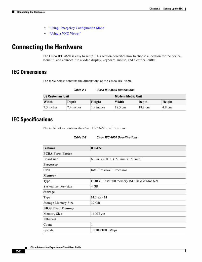
Connecting the HardwareThe Cisco IEC 4650 is easy to setup. This section describes how to choose a location for the device, mount it, and connect it to a video display, keyboard, mouse, and electrical outlet.
IEC DimensionsThe table below contains the dimensions of the Cisco IEC 4650.
Table 2-1 Cisco IEC 4650 Dimensions
IEC SpecificationsThe table below contains the Cisco IEC 4650 specifications.
Table 2-2 Cisco IEC 4650 Specifications
US Customary Unit Modern Metric Unit
Width Depth Height Width Depth Height
7.3 inches 7.4 inches 1.9 inches 18.5 cm 18.8 cm 4.8 cm
Features IEC 4650
PCBA Form Factor
Board size 6.0 in. x 6.0 in. (150 mm x 150 mm)
Processor
CPU Intel Broadwell Processor
Memory
Type DDR3-1333/1600 memory (SO-DIMM Slot X2)
System memory size 4 GB
Storage
Type M.2 Key M
Storage Memory Size 32 GB
BIOS Flash Memory
Memory Size 16 MByte
Ethernet
Count 1
Speeds 10/100/1000 Mbps
2-2Cisco Interactive Experience Client User Guide

Chapter 2 Setting Up the IECConnecting the Hardware
Connectors 1 Port RJ45 with transformer
Video
Onboard Intel HD5500 HDMI/Mini DisplayPort
Connectors 1 HDMI port
1 Mini DisplayPort
USB
Type USB 3.0 controller
Connectors 2 Right USB A type
2 Back USB A type
WiFi+Bluetooth
Count 1
Speed 802.11ac, Bluetooth 4.0
Front I/O
LED 1 Green LED
1 Orange LED
IR receiver 1 Built-in IR receiver
Back I/O
DC jack 1 12V DC in connector
Video 1 Mini DisplayPort
1 HDMI port
Ethernet 1 RJ45 connector with dual LEDs
USB 1 USB two-stack connector
Left I/O
COM 1 x 3.5 mm phone jack type
IR extension 1 1-IR 3.5 mm phone jack
Audio 1 Audio port (MIC-in)
1 Audio port (line-out)
USB 1 USB two-stack connector
Right I/O
Buttons 1 Power On/Off button (with soft/hard power option)
1 Reset button
Power
Adapter Delta DPS-65VB
Input 100V - 240V ~2A 50-60HZ
Output 12V~5.417A
Power consumption 12V@60W maximum
CPU VR Intel VR12.5/12.6
Features IEC 4650
2-3Cisco Interactive Experience Client User Guide

Chapter 2 Setting Up the IECConnecting the Hardware
Environmental Tolerance RangesRefer to the table below for the environmental tolerance ranges.
Table 2-3 Cisco IEC 4650 Environmental Tolerance Ranges: Temperature
Table 2-4 Cisco IEC 4650 Environmental Tolerance Ranges: Humidity
Table 2-5 Cisco IEC 4650 Environmental Tolerance Ranges: Altitude
Warnings
Warning Read the installation instructions before connecting the system to the power source.
Warning There is the danger of explosion if the battery is replaced incorrectly. Replace the battery only with the same or equivalent type recommended by the manufacturer. Dispose of used batteries according to the manufacturer’s instructions.
Warning Ultimate disposal of this product should be handled according to all national laws and regulations.
Temperature1 US Customary Unit Modern Metric Unit
Minimum Maximum Minimum Maximum
Operating long-term or short-term
32°F 104°F 0°C 40°C
Non-operating or storage
-4°F 158°F -20°C 70°C
1. Ambient.
Relative Humidity1 Minimum Maximum
Operating 10 percent (Indoor) 85 percent (Indoor)
Non-operating or storage 0 percent (Indoor and Outdoor) 95 percent (Indoor and Outdoor)
1. Noncondensing; ambient.
Altitude1 US Customary Unit Modern Metric Unit
Minimum Maximum Minimum Maximum
Operating and non-operating
0 feet 6,561 feet 0 meters 2,000 meters
1. Above sea level.
2-4Cisco Interactive Experience Client User Guide

Chapter 2 Setting Up the IECConnecting the Hardware
VCCI-B Warning - Japan
この装置は、クラス B 情報枝術装置です。この装置は、家庭環境で使用することを目的としていますが、こ の装置がラジオやテレビジョン受信機に近接して使用されると、受信障害を引き起こすことがあります。取扱説明書に従って正しい取り扱いをして下さい。VCCI-B
This is a Class B product based on the standard of the VCCI Council. If this is used near a radio or television receiver in a domestic environment, it may cause radio interference. Install and use the equipment according to the instruction manual. VCCI-B
EMC Warning - South Korea
Table 2-6 Class A and Class B EMC Registration
RF Warning - South Korea
노출 요구사항을 준수하기 위해 신체에 착용한 상태로 실행 시 사용자의 신체와 안테나를포함한 기기 간에는 최소 이격 거리인 1.5cm가 유지되어야 합니다 .(Translation: A minimum separation distance of 1.5 cm must be maintained between the user's body and the device, including the antenna during body-worn operation to comply with RF exposure requirement.)
產品 0cm fail, 可以拉距離測試 , limit 是 2.5cm, 要在手冊加警語
Federal Communication Commission Interference Statement - USAThis device complies with Part 15 of the FCC Rules. Operation is subject to the following two conditions: (1) This device may not cause harmful interference, and (2) this device must accept any interference received, including interference that may cause undesired operation.
A급 기기 : 업무용 방송통신기자재
Class A: Industrial/Official
이 기기는 업무용 (A급 ) 전자파적합기기로서 판매자 또는 사용자는 이 점을 주의하시기 바라며 , 가정외의 지역에서 사용하는 것을 목적으로 합니다 .
As this equipment has undergone EMC registration for business purpose (“A” class). the seller and/or the buyer is asked to beware of this point and designed to be used in the area, except for home use.
B급 기기 : 가정용 방송통신기자재
Class B: Home
이 기기는 가정용 (B급 ) 전자파적합기기로서 주로 가정에서 사용하는 것을 목적으로 하며 , 모든 지역에서 사용할 수 있습니다
As this equipment has undergone EMC registration for household purpose (“B” class). this product can be used in any area and designed to be used mainly in a household.
2-5Cisco Interactive Experience Client User Guide

Chapter 2 Setting Up the IECConnecting the Hardware
This equipment has been tested and found to comply with the limits for a Class B digital device, pursuant to Part 15 of the FCC Rules. These limits are designed to provide reasonable protection against harmful interference in a residential installation. This equipment generates, uses and can radiate radio frequency energy and, if not installed and used in accordance with the instructions, may cause harmful interference to radio communications. However, there is no guarantee that interference will not occur in a particular installation. If this equipment does cause harmful interference to radio or television reception, which can be determined by turning the equipment off and on, the user is encouraged to try to correct the interference by one of the following measures:
• Reorient or relocate the receiving antenna.
• Increase the separation between the equipment and receiver.
• Connect the equipment into an outlet on a circuit different from that to which the receiver is connected.
• Consult the dealer or an experienced radio/TV technician for help.
Caution Any changes or modifications not expressly approved by the party responsible for compliance could void the user's authority to operate this equipment.
RF ExposureThe Cisco products are designed to comply with the following national and international standards on Human Exposure to Radio Frequencies.
• US 47 Code of Federal Regulations Part 2 Subpart J
• American National Standards Institute (ANSI) / Institute of Electrical and Electronic Engineers / IEEE C 95.1 (99)
• International Commission on Non Ionizing Radiation Protection (ICNIRP) 98
• Ministry of Health (Canada) Safety Code 6. Limits on Human Exposure to Radio Frequency Fields in the range from 3kHz to 300 GHz
• Australia Radiation Protection Standard
Caution To ensure compliance with various national and international Electromagnetic Field (EMF) standards, the system should only be operated with Cisco approved antennas and accessories.
THIS DEVICE MEETS THE FCC GUIDELINES FOR EXPOSURE TO RADIO WAVES
Your device includes a radio transmitter and receiver. It is designed not to exceed the limits for exposure to radio waves (radio frequency electromagnetic fields) as referenced in FCC Part 1.1310. The guidelines are based on IEEE ANSI C 95.1 (92) and include a substantial safety margin designed to assure the safety of all persons, regardless of age and health.
As such the systems are designed to be operated as to avoid contact with the antennas by the end user. It is recommended to set the system in a location where the antennas can remain at least a minimum distance as specified from the user in accordance to the regulatory guidelines which are designed to reduce the overall exposure of the user or operator.
The device has been tested and found compliant with the applicable regulations as part of the radio certification process.
2-6Cisco Interactive Experience Client User Guide

Chapter 2 Setting Up the IECConnecting the Hardware
Table 2-7 Separation Distance
The US Food and Drug Administration has stated that present scientific information does not indicate the need for any special precautions for the use of wireless devices. The FCC recommends that if you are interested in further reducing your exposure then you can easily do so by reorienting antennas away from the user or placing the antennas at a greater separation distance then recommended or lowering the transmitter power output.
THIS DEVICE MEETS THE HEALTH CODE 6 GUIDELINES FOR EXPOSURE TO RADIO WAVES
The device has been evaluated and found compliant with the requirements set forth in Industry Canada RSS-102, Evaluation Procedure for Mobile and Portable Radio Transmitters with respect to health Canada Safety Code 6 for Exposure of Humans to Radio Frequency Fields.
Health Canada states that present scientific information does not indicate the need for any special precautions for the use of wireless devices.
THIS DEVICE MEETS INTERNATIONALGUIDELINES FOR EXPOSURE TO RADIO WAVES
Your device includes a radio transmitter and receiver. It is designed not to exceed the limits for exposure to radio waves (radio frequency electromagnetic fields) recommended by international guidelines. The guidelines were developed by an independent scientific organization (ICNIRP) and include a substantial safety margin designed to assure the safety of all persons, regardless of age and health.
As such the systems are designed to be operated as to avoid contact with the antennas by the end user. It is recommended to set the system in a location where the antennas can remain at least a minimum distance as specified from the user in accordance to the regulatory guidelines which are designed to reduce the overall exposure of the user or operator.
Table 2-8 Separation Distance
The World Health Organization has stated that present scientific information does not indicate the need for any special precautions for the use of wireless devices.
However if you are interested in further reducing your exposure then you can easily do so by reorienting antennas away from the user or placing the antennas at a greater separation distance then recommended.
Additional information on the subject can be found at the following links
• FCC Web site: http://www.fcc.gov/encyclopedia/radio-frequency-safety
• FDA Website http://www.fda.gov
• Health Canada: http://hc-sc.gc.ca/ewh-semt/radiation/index-eng.php
• World Health Organization Internal Commission on Non-Ionizing Radiation Protection at www.who.int/emf
• Mobile Manufacturers Forum at www.mmfai.org
MPE Distance Limit
x.xxx
mW^cm 2
x cm / x inches x.xx
mW/cm^2
MPE Distance Limit
x.xxx
mW^cm 2
x cm / x inches x.xx
mW/cm^2
2-7Cisco Interactive Experience Client User Guide
Chapter 2 Setting Up the IECConnecting the Hardware
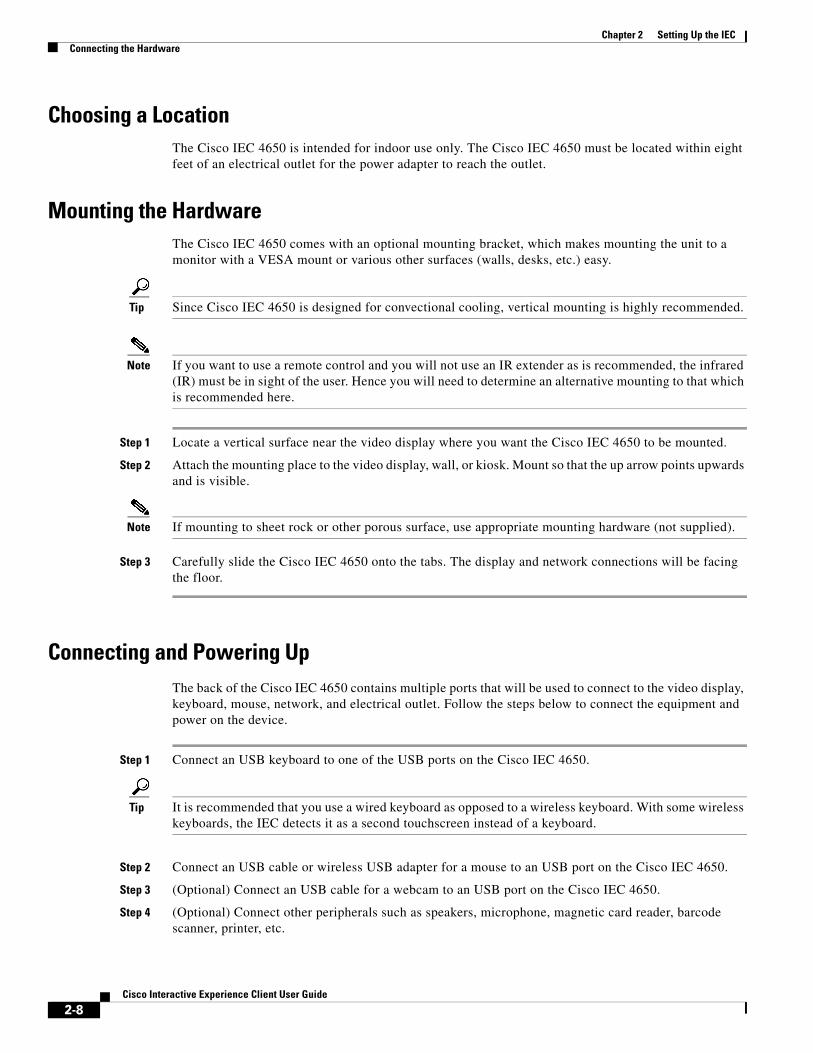
Choosing a LocationThe Cisco IEC 4650 is intended for indoor use only. The Cisco IEC 4650 must be located within eight feet of an electrical outlet for the power adapter to reach the outlet.
Mounting the HardwareThe Cisco IEC 4650 comes with an optional mounting bracket, which makes mounting the unit to a monitor with a VESA mount or various other surfaces (walls, desks, etc.) easy.
Tip Since Cisco IEC 4650 is designed for convectional cooling, vertical mounting is highly recommended.
Note If you want to use a remote control and you will not use an IR extender as is recommended, the infrared (IR) must be in sight of the user. Hence you will need to determine an alternative mounting to that which is recommended here.
Step 1 Locate a vertical surface near the video display where you want the Cisco IEC 4650 to be mounted.
Step 2 Attach the mounting place to the video display, wall, or kiosk. Mount so that the up arrow points upwards and is visible.
Note If mounting to sheet rock or other porous surface, use appropriate mounting hardware (not supplied).
Step 3 Carefully slide the Cisco IEC 4650 onto the tabs. The display and network connections will be facing the floor.
Connecting and Powering UpThe back of the Cisco IEC 4650 contains multiple ports that will be used to connect to the video display, keyboard, mouse, network, and electrical outlet. Follow the steps below to connect the equipment and power on the device.
Step 1 Connect an USB keyboard to one of the USB ports on the Cisco IEC 4650.
Tip It is recommended that you use a wired keyboard as opposed to a wireless keyboard. With some wireless keyboards, the IEC detects it as a second touchscreen instead of a keyboard.
Step 2 Connect an USB cable or wireless USB adapter for a mouse to an USB port on the Cisco IEC 4650.
Step 3 (Optional) Connect an USB cable for a webcam to an USB port on the Cisco IEC 4650.
Step 4 (Optional) Connect other peripherals such as speakers, microphone, magnetic card reader, barcode scanner, printer, etc.
2-8Cisco Interactive Experience Client User Guide

Chapter 2 Setting Up the IECRegistering the IEC
Note If using the RS232 port for a RCA, TRS, or TRRS connector, the tip of the connector corresponds to pin 2 and the ring of the connector corresponds to pin 3 on a DB-9 connector.
Step 5 Connect the video display cable to either the HDMI port or Mini DisplayPort on the Cisco IEC 4650. Then connect the other end of the cable to the video display.
Tip To optimize the video quality, the Cisco IEC 4650 should be connected to a 1080p or 4K LED or LCD video display using the HDMI or Mini DisplayPort cable.
Step 6 If the display is a touch screen, connect an USB cable to it and an USB interface on the Cisco IEC 4650.
Step 7 Plug the power cord for the video display into an electrical outlet.
Step 8 Turn on the power to the video display.
Step 9 Connect an Ethernet cable to the LAN port on the Cisco IEC 4650. Connect the other end of the Ethernet cable to an Ethernet wall jack or Ethernet port on a router or switch.
Step 10 Connect the power adapter to the DC 12V in connector on the Cisco IEC 4650.
Step 11 Plug the power adapter into an electrical outlet.
The Cisco IEC 4650 will initialize now. When it finishes initializing, the COBRA screen appears.
Note After initialization “Startup URL is not configured” will appear at the top of the screen. It is referring to the URL that the Cisco IEC 4650 will use to display content once it is configured.
Record the serial number and IP address shown on the COBRA screen.
Note If there are any problems with the initial configuration or the network, the system will not initialize and the Cobra screen will not appear. If that happens, refer to “Using Emergency Configuration Mode”.
Registering the IECThe Cisco IEC 4650 must first be registered in the IEM to manage it remotely. To register a device, you will need the following:
• Enough licenses in the IEM to cover the new device
• The IEC’s serial number, which can be found on the bottom of the device
• User credentials on the IEM
A license for the device must exist in the IEM before the device can be registered. If a license does not exist in the IEM to cover the device, the device will not register and it cannot be managed by the IEM until a license is obtained for it. For more information about licensing, refer to the Cisco Interactive Experience Manager Administrator Guide.
You will register the IEC using the New Device button within the Devices’ Edit menu. Refer to the “Adding a New Device” section of the Cisco Interactive Experience Manager Administrator Guide for instructions on how to add the device.
2-9Cisco Interactive Experience Client User Guide
Chapter 2 Setting Up the IECConfiguring the System
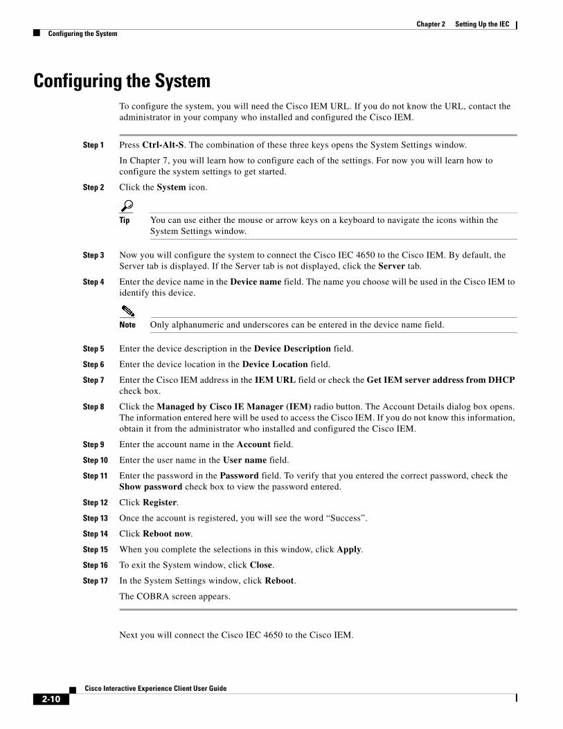
Configuring the SystemTo configure the system, you will need the Cisco IEM URL. If you do not know the URL, contact the administrator in your company who installed and configured the Cisco IEM.
Step 1 Press Ctrl-Alt-S. The combination of these three keys opens the System Settings window.
In Chapter 7, you will learn how to configure each of the settings. For now you will learn how to configure the system settings to get started.
Step 2 Click the System icon.
Tip You can use either the mouse or arrow keys on a keyboard to navigate the icons within the System Settings window.
Step 3 Now you will configure the system to connect the Cisco IEC 4650 to the Cisco IEM. By default, the Server tab is displayed. If the Server tab is not displayed, click the Server tab.
Step 4 Enter the device name in the Device name field. The name you choose will be used in the Cisco IEM to identify this device.
Note Only alphanumeric and underscores can be entered in the device name field.
Step 5 Enter the device description in the Device Description field.
Step 6 Enter the device location in the Device Location field.
Step 7 Enter the Cisco IEM address in the IEM URL field or check the Get IEM server address from DHCP check box.
Step 8 Click the Managed by Cisco IE Manager (IEM) radio button. The Account Details dialog box opens. The information entered here will be used to access the Cisco IEM. If you do not know this information, obtain it from the administrator who installed and configured the Cisco IEM.
Step 9 Enter the account name in the Account field.
Step 10 Enter the user name in the User name field.
Step 11 Enter the password in the Password field. To verify that you entered the correct password, check the Show password check box to view the password entered.
Step 12 Click Register.
Step 13 Once the account is registered, you will see the word “Success”.
Step 14 Click Reboot now.
Step 15 When you complete the selections in this window, click Apply.
Step 16 To exit the System window, click Close.
Step 17 In the System Settings window, click Reboot.
The COBRA screen appears.
Next you will connect the Cisco IEC 4650 to the Cisco IEM.
2-10Cisco Interactive Experience Client User Guide
Chapter 2 Setting Up the IECConnecting to the Network
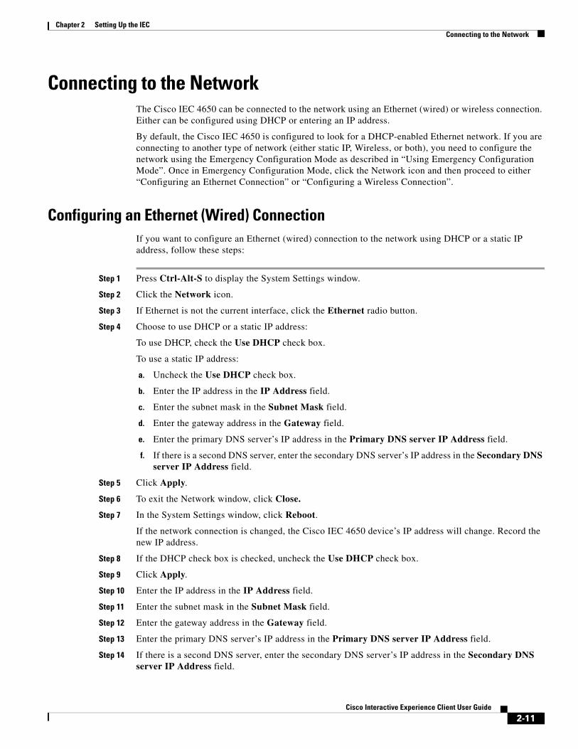
Connecting to the NetworkThe Cisco IEC 4650 can be connected to the network using an Ethernet (wired) or wireless connection. Either can be configured using DHCP or entering an IP address.
By default, the Cisco IEC 4650 is configured to look for a DHCP-enabled Ethernet network. If you are connecting to another type of network (either static IP, Wireless, or both), you need to configure the network using the Emergency Configuration Mode as described in “Using Emergency Configuration Mode”. Once in Emergency Configuration Mode, click the Network icon and then proceed to either “Configuring an Ethernet Connection” or “Configuring a Wireless Connection”.
Configuring an Ethernet (Wired) ConnectionIf you want to configure an Ethernet (wired) connection to the network using DHCP or a static IP address, follow these steps:
Step 1 Press Ctrl-Alt-S to display the System Settings window.
Step 2 Click the Network icon.
Step 3 If Ethernet is not the current interface, click the Ethernet radio button.
Step 4 Choose to use DHCP or a static IP address:
To use DHCP, check the Use DHCP check box.
To use a static IP address:
a. Uncheck the Use DHCP check box.
b. Enter the IP address in the IP Address field.
c. Enter the subnet mask in the Subnet Mask field.
d. Enter the gateway address in the Gateway field.
e. Enter the primary DNS server’s IP address in the Primary DNS server IP Address field.
f. If there is a second DNS server, enter the secondary DNS server’s IP address in the Secondary DNS server IP Address field.
Step 5 Click Apply.
Step 6 To exit the Network window, click Close.
Step 7 In the System Settings window, click Reboot.
If the network connection is changed, the Cisco IEC 4650 device’s IP address will change. Record the new IP address.
Step 8 If the DHCP check box is checked, uncheck the Use DHCP check box.
Step 9 Click Apply.
Step 10 Enter the IP address in the IP Address field.
Step 11 Enter the subnet mask in the Subnet Mask field.
Step 12 Enter the gateway address in the Gateway field.
Step 13 Enter the primary DNS server’s IP address in the Primary DNS server IP Address field.
Step 14 If there is a second DNS server, enter the secondary DNS server’s IP address in the Secondary DNS server IP Address field.
2-11Cisco Interactive Experience Client User Guide
Chapter 2 Setting Up the IECConnecting to the Network
Step 15 When you complete the selections in this window, click Apply.
Step 16 To exit the Network window, click Close.
Step 17 In the System Settings window, click Reboot.
If you change the network connection, the Cisco IEC 4650 device’s IP address will change. Be sure to record the new IP address.
Configuring a Wireless ConnectionIf you want to configure a wireless connection to the network using DHCP or a static IP address, follow these steps:
Step 1 Press Ctrl-Alt-S to display the System Settings window.
Step 2 Click the Network icon.
Step 3 Click the Wireless radio button.
Step 4 Click Scan.
All the wireless networks detected are displayed.
Step 5 Click a network name to select a network.
Step 6 In the Security tab, enter the information requested.
• If the security type is WEP:
– From the Key Type drop-down list, choose ASCII or HEX.
– Enter the key in the Key field
• If the security type is WPA Personal or WPA2 Personal:
– Enter the passphrase in the Passphrase field.
• If the security type is WPA Enterprise or WPA2 Enterprise:
– Enter the user name in the User Name field.
– Enter the password in the Password field.
– Enter the anonymous identity in the Anonymous Identity field.
– From the EAP Method drop-down list, choose the EAP method used.
– From the Inner Method drop-down list, choose the inner method used.
– If it requires a SSL certificate, check the Use SSL Certificate check box.
• If the security type is IEEE802.1X:
– Enter the user name in the User Name field.
– Enter the password in the Password field.
– Enter the anonymous identity in the Anonymous Identity field.
– From the EAP Method drop-down list, choose the EAP method used.
– From the Inner Method drop-down list, choose the inner method used.
– If it requires a SSL certificate, check the Use SSL Certificate check box.
2-12Cisco Interactive Experience Client User Guide
Chapter 2 Setting Up the IECConnecting to the Cisco IEM
Step 7 Click the IP address tab.
Step 8 Choose to use DHCP or a static IP address:
To use DHCP, check the Use DHCP check box.
To use a static IP address:
a. Uncheck the Use DHCP check box.
b. Enter the IP address in the IP Address field.
c. Enter the subnet mask in the Subnet Mask field.
d. Enter the gateway address in the Gateway field.
e. Enter the primary DNS server’s IP address in the Primary DNS server IP Address field.
f. If there is a second DNS server, enter the secondary DNS server’s IP address in the Secondary DNS server IP Address field.
Step 9 Click Apply.
Step 10 To exit the Network window, click Close.
Step 11 In the System Settings window, click Reboot.
If you change the network connection, the Cisco IEC 4650 device’s IP address will change. Be sure to record the new IP address.
Connecting to the Cisco IEMThis section assumes that either you or an administrator at your company has already installed and configured the Cisco IEM. If not, use the Cisco Interactive Experience Manager Installation Guide and Cisco Interactive Experience Manager Administrator Guide to install and configure the Cisco IEM.
Applying a PolicyThe startup URL is the content that will be displayed on the kiosk. Follow these steps to apply a policy on the device so that the startup URL appears on the kiosk display.
Step 1 Open a browser on your computer.
Step 2 Enter the Cisco IEM URL.
Step 3 Enter the account name in the Account field.
Step 4 Enter the user name in the User Name field.
Step 5 Enter the password in the Password field.
Step 6 Click Enter.
After login, the Cisco IEM opens.
Step 7 In the left pane, choose Devices.
2-13Cisco Interactive Experience Client User Guide
Chapter 2 Setting Up the IECCalibrating the Touchscreen
Step 8 Double-click the device’s icon in the center pane.
Step 9 To get the startup URL, you need to apply a policy. Click the Policies tab.
Step 10 Ask your administrator which policy you should apply.
Step 11 From the Available policies list, choose the policy.
Step 12 Click the Green Arrow to move that policy to the Applied policies list
You can select more than one policy at a time by pressing Select (for sequential policies) or CTRL (for non-sequential policies).
Step 13 Click Apply.
Step 14 In the right pane, click Predefined actions to display the list of Predefined actions.
Step 15 Click Reboot.
Step 16 Click Ok in the Reboot Device dialog box to reboot the Cisco IEC 4650.
The video display will now show the content from the startup URL. If you want to change how the startup URL appears, refer to the Cisco Interactive Experience Manager Administrator Guide.
Calibrating the TouchscreenWhen the calibration screen appears, touch the crosses in the corners as instructed. For example, when the touchscreen is in portrait orientation, touch the screen in this order: top right, bottom right, top left, and bottom left.
You can calibrate the screen at any time. To calibrate the touchscreen, follow these steps:
Step 1 Press Ctrl-Alt-S to access the System Settings menu.
Step 2 Click the Calibrator button.
The calibration utility will start. When it is finished, the startup URL content is displayed on the touchscreen.
Using Emergency Configuration Mode
Note Using the emergency configuration mode should be your last resort. This is primarily done if you do not have Internet access and you have tried to solve the issue to no avail. Consult the Cisco Interactive Experience Platform Troubleshooting Guide first.
If the system hangs during the initialization process, enter the Emergency Configuration Mode to modify the configuration.
To use Emergency Configuration Mode, do the following:
Step 1 Log into the IEM.
2-14Cisco Interactive Experience Client User Guide
Chapter 2 Setting Up the IECUsing a VNC Viewer
Step 2 Click Devices in the left pane.
Step 3 Double-click on the device icon to display the tabs containing information about that particular device.
Step 4 In the General tab, click on the Maintenance Code button.
The maintenance code is displayed. Write down the code.
Step 5 Go to the Cisco IEC 4650.
Step 6 Click on the gear button on the screen.
You will be prompted for an access code.
Step 7 Enter the maintenance code.
Using a VNC ViewerThe IEC can be accessed by a VNC viewer. VNC is enabled or disabled in the IEM. The instructions below explain how to create a custom action for VNC, set the remoteview.enabled property in the IEM to ‘true’, and then launch the VNC viewer.
You will need the following:
1. The IEC’s Maintenance Code, which can be found in the General Tab of the device (see figure below)
2. A VNC viewer
To use a VNC viewer to access an IEC, follow these steps:
Step 1 Log into the IEM.
Step 2 Click Policies in the left pane.
Step 3 In the Edit menu, click New Policy.
Step 4 Enter a policy name in the Policy Name field that indicates the purpose of this policy such as “VNC_Start” or “VNC_Viewer”.
Step 5 Check the Is action check box to make this policy runtime.
Step 6 Check the Add to custom actions checkbox to create a custom action.
Step 7 Click Create.
Step 8 After the policy is created, open the policy and click the Policy tab.
Step 9 Find the remoteview > enabled property.
Step 10 Change the value to true.
Step 11 Click Apply.
Step 12 When you are ready to use a VNC viewer to access an IEC, go to the IEM and find the device that you want to access using a VNC viewer.
Step 13 From the Custom actions menu, click the custom action that you created for VNC such as “VNC_Start”.
Step 14 Launch a VNC viewer.
2-15Cisco Interactive Experience Client User Guide

Chapter 2 Setting Up the IECUsing a VNC Viewer
Step 15 In the VNC Server field, enter the IEC’s IP address followed by a colon and the port number. For example, 188.32.16.55:5980.
Step 16 Click Connect.
Step 17 When prompted for a password, enter the IEC’s Maintenance Code.
Note When entering the Maintenance Code as the password, enter the letters of the Maintenance Code as upper case. If for example the Maintenance Code is 6A54F3, enter “6A54F3”. The password will not work if you enter “6a54f3”.
The screen will then show the application that is currently running on the IEC.
2-16Cisco Interactive Experience Client User Guide

C H A P T E R 3
Configuring SettingsRevised: February 16, 2016
Chapter Overview
Note The Cisco IEC 4650 should be configured from the IEM by applying policies and configuring its profile. This chapter is only for configuration of a single IEC that is not connected to an IEM such as for demo purposes.
This chapter explains how to use the System Settings menu to configure the Cisco IEC 4650 settings for the network, proxy, and system. It also explains how to sort logs and reboot the Cisco IEC.
The topics in this chapter include the following:
• “Network Settings”
– “Configuring an Ethernet Connection using DHCP”
– “Configuring an Ethernet Connection using a Static IP Address”
– “Configuring a Wireless Connection using DHCP”
– “Configuring a Wireless Connection using a Static IP Address”
• “Proxy Server Settings”
– “Static Option”
– “Autoconfiguration Script Option”
– “Autoconfiguration URL Option”
• “System Settings”
– “Setting Management Mode”
– “Setting Standalone Mode”
– “Changing the IEM’s URL”
• “System Logs”
– “Sorting Logs”
– “Enabling the Debug Mode”
• “Reboot”
3-1Cisco Interactive Experience Client User Guide
Chapter 3 Configuring SettingsNetwork Settings
Network SettingsThe Cisco IEC 4650 can be connected to the network using an Ethernet (wired) or wireless connection. Either can be configured using DHCP or an IP address.
Configuring an Ethernet Connection using DHCPIf you want to configure an Ethernet (wired) connection to your network using DHCP, follow these steps:
Step 1 Press Ctrl-Alt-S to display the System Settings window.
Step 2 Click the Network icon.
Step 3 If Ethernet is not the current interface, click on the Ethernet radio button.
Step 4 If the DHCP check box is not checked, check the Use DHCP check box.
Step 5 Click Apply.
Step 6 To exit the Network window, click Close.
Step 7 In the System Settings window, click Reboot.
If you change the network connection, the Cisco IEC 4650 device’s IP address will change. Be sure to record the new IP address.
Configuring an Ethernet Connection using a Static IP AddressIf you want to configure an Ethernet (wired) connection to your network using a static IP address, follow these steps:
Step 1 Press Ctrl-Alt-S to display the System Settings window.
Step 2 Click the Network icon.
Step 3 If Ethernet is not the current interface, click on the Ethernet radio button.
Step 4 If the DHCP check box is checked, uncheck the Use DHCP check box.
Step 5 Enter the IP address in the IP Address field.
Step 6 Enter the subnet mask in the Subnet Mask field.
Step 7 Enter the gateway address in the Gateway field.
Step 8 Enter the primary DNS server’s IP address in the Primary DNS server IP Address field.
Step 9 If there is a second DNS server, enter the secondary DNS server’s IP address in the Secondary DNS server IP Address field.
Step 10 When you complete the selections in this window, click Apply.
Step 11 To exit the Network window, click Close.
3-2Cisco Interactive Experience Client User Guide
Chapter 3 Configuring SettingsNetwork Settings
Step 12 In the System Settings window, click Reboot.
If you change the network connection, the Cisco IEC 4650 device’s IP address will change. Be sure to record the new IP address.
Configuring a Wireless Connection using DHCPIf you want to configure a wireless connection to your network using DHCP, follow these steps:
Step 1 Press Ctrl-Alt-S to display the System Settings window.
Step 2 Click the Network icon.
Step 3 Click the Wireless radio button.
Step 4 Click Scan.
Step 5 Click on a network name to select a network.
Step 6 In the Security tab, enter the information requested.
• If the security type is WEP:
– From the Key Type drop-down list, choose ASCII or HEX.
– Enter the key in the Key field.
• If the security type is WPA Personal or WPA2 Personal:
– Enter the passphrase in the Passphrase field.
• If the security type is WPA Enterprise or WPA2 Enterprise:
– Enter the user name in the User Name field.
– Enter the password in the Password field.
– Enter the anonymous identity in the Anonymous Identity field.
– From the EAP Method drop-down list, choose the EAP method used.
– From the Inner Method drop-down list, choose the inner method used.
– If it requires a SSL certificate, check the Use SSL Certificate check box.
• If the security type is IEEE802.1X:
– Enter the user name in the User Name field.
– Enter the password in the Password field.
– Enter the anonymous identity in the Anonymous Identity field.
– From the EAP Method drop-down list, choose the EAP method used.
– From the Inner Method drop-down list, choose the inner method used.
– If it requires a SSL certificate, check the Use SSL Certificate check box.
Step 7 Click on the IP address tab.
3-3Cisco Interactive Experience Client User Guide
Chapter 3 Configuring SettingsNetwork Settings
Step 8 If the DHCP check box is not checked, check the Use DHCP check box.
Step 9 Click Apply.
Step 10 To exit the Network window, click Close.
Step 11 In the System Settings window, click Reboot.
If you change the network connection, the Cisco IEC 4650 device’s IP address will change. Be sure to record the new IP address.
Configuring a Wireless Connection using a Static IP AddressIf you want to configure a wireless connection to your network using a static IP address, follow these steps:
Step 1 Press Ctrl-Alt-S to display the System Settings window.
Step 2 Click the Network icon.
Step 3 Click the Wireless radio button.
Step 4 Click Scan.
Step 5 Click on a network name to select a network.
Step 6 In the Security tab, enter the information requested.
• If the security type is WEP:
– From the Key Type drop-down list, choose ASCII or HEX.
– Enter the key in the Key field.
• If the security type is WPA Personal or WPA2 Personal:
– Enter the passphrase in the Passphrase field.
• If the security type is WPA Enterprise or WPA2 Enterprise:
– Enter the user name in the User Name field.
– Enter the password in the Password field.
– Enter the anonymous identity in the Anonymous Identity field.
– From the EAP Method drop-down list, choose the EAP method used.
– From the Inner Method drop-down list, choose the inner method used.
– If it requires a SSL certificate, check the Use SSL Certificate check box.
• If the security type is IEEE802.1X:
– Enter the user name in the User Name field.
– Enter the password in the Password field.
– Enter the anonymous identity in the Anonymous Identity field.
– From the EAP Method drop-down list, choose the EAP method used.
3-4Cisco Interactive Experience Client User Guide
Chapter 3 Configuring SettingsProxy Server Settings
– From the Inner Method drop-down list, choose the inner method used.
– If it requires a SSL certificate, check the Use SSL Certificate check box.
Step 7 Click on the IP address tab.
Step 8 If the DHCP check box is checked, uncheck the Use DHCP check box.
Step 9 Enter the IP address in the IP Address field.
Step 10 Enter the subnet mask in the Subnet Mask field.
Step 11 Enter the gateway address in the Gateway field.
Step 12 Enter the primary DNS server’s IP address in the Primary DNS server IP Address field.
Step 13 If there is a second DNS server, enter the secondary DNS server’s IP address in the Secondary DNS server IP Address field.
Step 14 When you complete the selections in this window, click Apply.
Step 15 To exit the Network window, click Close.
Step 16 In the System Settings window, click Reboot.
If you change the network connection, the Cisco IEC 4650 device’s IP address will change. Be sure to record the new IP address.
Proxy Server SettingsThe proxy settings only apply to standalone mode. If you are in standalone mode, you can enable a proxy server.
There are four configuration options:
• Disabled
• Static
• Autoconfiguration script
• Autoconfiguration URL
By default, the proxy server is disabled.
Static OptionFollow these steps to enable a proxy server using the static option:
Step 1 Press Ctrl-Alt-S to display the System Settings window.
Step 2 If the IEC is managed by an IEM, enter its maintenance code.
Step 3 Click the Proxy Server icon.
Step 4 In the Proxy Server dialog box, choose the Static radio button as proxy type.
Step 5 Enter the host address in the Host field.
3-5Cisco Interactive Experience Client User Guide
Chapter 3 Configuring SettingsProxy Server Settings
Step 6 Set the port number by using the arrows or entering a value in the Port field.
Step 7 Enter the user name in the User name field.
Step 8 Enter the password in the Password field.
Step 9 When you complete the selections in this window, click Apply.
Step 10 To exit the Proxy Server window, click Close.
Step 11 In the System Settings window, click Reboot.
Autoconfiguration Script OptionFollow these steps to enable a proxy server using an autoconfiguration script:
Step 1 Press Ctrl-Alt-S to display the System Settings window.
Step 2 If the IEC is managed by an IEM, enter its maintenance code.
Step 3 Click the Proxy Server icon.
Step 4 In the Proxy Server dialog box, choose the Autoconfiguration script radio button as proxy type.
Step 5 Enter the proxy script in the Script field.
Step 6 Click Apply.
Step 7 To exit the Proxy Server window, click Close.
Step 8 In the System Settings window, click Reboot.
Autoconfiguration URL OptionFollow these steps to enable a proxy server using an autoconfiguration URL:
Step 1 Press Ctrl-Alt-S to display the System Settings window.
Step 2 If the IEC is managed by an IEM, enter its maintenance code.
Step 3 Click the Proxy Server icon.
Step 4 In the Proxy Server dialog box, choose the Autoconfiguration URL radio button as proxy type.
Step 5 Enter the URL of the PAC file or web server in the URL field.
Step 6 Click Apply.
Step 7 To exit the Proxy Server window, click Close.
Step 8 In the System Settings window, click Reboot.
3-6Cisco Interactive Experience Client User Guide

Chapter 3 Configuring SettingsSystem Settings
System SettingsThere are three tabs in the System settings window: Server, Device, and LAN. To configure the system, you will need the Cisco IEM URL. If you do not know the URL, contact the administrator in your company who installed and configured the Cisco IEM.
Setting Management ModeIn managed mode, the Cisco IEC 4650 is configured and controlled remotely. Managed mode facilitates consistency and is the recommended (and default) mode.
Step 1 Press Ctrl-Alt-S to display the System Settings window.
Step 2 Click the System icon.
Now you will configure the system to connect the Cisco IEC 4650 device to the Cisco IEM.
Step 3 Enter the device name in the Device name field. The name you choose will be used in the Cisco IEM to identify this device.
Step 4 Enter the device description in the Device Description field.
Step 5 Enter the device location in the Device Location field.
Step 6 Enter the Cisco IEM address in the Manager host field.
Step 7 Click the Switch to managed button. The Account Details dialog box opens. The information entered here will be used to access the Cisco IEM. If you do not know this information, obtain it from the administrator who installed and configured the Cisco IEM.
Step 8 Enter the account name in the Account field.
Step 9 Enter the user name in the User name field.
Step 10 Enter the password in the Password field. To verify that you entered the correct password, check the Show password check box to see the characters entered.
Step 11 Click Register.
Step 12 Once the account is registered, you will see the word “Success”.
Step 13 Click Reboot now.
Setting Standalone ModeIf you will not use the Cisco IEM to manage the kiosk, configure the Cisco IEC 4650 using the standalone mode.
Warning If you have already registered a Cisco IEM account, choosing standalone will unregister that account.
Step 1 Press Ctrl-Alt-S to display the System Settings window.
Step 2 Click the System icon.
3-7Cisco Interactive Experience Client User Guide

Chapter 3 Configuring SettingsSystem Settings
Step 3 Enter the device name in the Device name field.
Step 4 Enter the device description in the Device Description field.
Step 5 Enter the device location in the Device Location field.
Step 6 Click the Switch to standalone button.
Step 7 In the Account Details dialog box, enter the account name in the Account field.
Step 8 Enter the user name in the User name field.
Step 9 Enter the password in the Password field. To verify that you entered the correct password, check the Show password check box to see the characters entered.
Step 10 Click Unregister.
Step 11 Once the account is unregistered, you will see the word “Success”.
Step 12 Click the Reboot now button.
Changing the IEM’s URLThere may be times when you need to change the IEM’s URL in the IEC to a different IEM URL such as when the IEC is used for demos that use multiple instances of IEMs. If you need to change the IEM’s URL in the IEC, follow the steps below.
Step 1 Press Ctrl-Alt-S to display the System Settings window.
Step 2 Click the System icon.
Step 3 In the System dialog box, enter the device name in the Device name field.
Step 4 Enter the device description in the Device Description field.
Step 5 Enter the device location in the Device Location field.
Step 6 Click the Switch to standalone button.
Step 7 In the Account Details dialog box, enter the account name in the Account field.
Step 8 Enter the user name in the User name field.
Step 9 Enter the password in the Password field. To verify that you entered the correct password, check the Show password check box to see the characters entered.
Step 10 Click the Unregister button.
Step 11 Once the account is unregistered, you will see the word “Success”.
Step 12 Click the Reboot now button. The IEC will reboot.
Step 13 After the IEC reboots, press Ctrl-Alt-S to display the System Settings window.
Step 14 Click the System icon.
Step 15 In the System dialog box, enter the device name in the Device name field.
Step 16 Enter the device description in the Device Description field.
Step 17 Enter the device location in the Device Location field.
Step 18 Enter the new IEM address in the Manager host field.
3-8Cisco Interactive Experience Client User Guide
Chapter 3 Configuring SettingsSystem Logs
Step 19 Click the Switch to managed button.
Step 20 Enter the account name for the new IEM in the Account field.
Step 21 Enter the user name in the User name field.
Step 22 Enter the password in the Password field. To verify that you entered the correct password, check the Show password check box to see the characters entered.
Step 23 Click the Register button.
Step 24 Once the account is registered, you will see the word “Success”.
Step 25 Click the Reboot now button.
Resetting the DeviceThe Cisco IEC 4650 can be reset to factory settings at any time.
There are two methods for resetting the device to factory settings:
1. Insert a pin in the Reset hole on the side of the IEC and hold it for five seconds.
2. Click the Reset to defaults button in the Device tab. Follow the steps below to reset the device to factory settings using this option.
Step 1 Press Ctrl-Alt-S to display the System Settings window.
Step 2 Click the System icon.
Step 3 Click the Device tab.
Step 4 Click Reset to defaults. The Reset dialog box opens.
Step 5 Click Yes.
System LogsThe System Logs window displays all the data collected since the device was last powered on. The Cisco IEC 4650 is a stateless device so if the device is unplugged or loses power, the data is lost.
You can sort data five ways:
• Severity – You can sort by level of severity from highest to lowest: critical, error, warning, notice, information, debug.
• Time – You can sort by when the data was collected.
• Application – You can sort by the type of component.
• Process identifier (PID) – You can sort by the process identifier (PID), the unique number assigned to every process running in the system.
• Message – You can sort by message types.
3-9Cisco Interactive Experience Client User Guide
Chapter 3 Configuring SettingsSystem Logs
Sorting LogsFollow these steps to sort the log entries:
Step 1 Press Ctrl-Alt-S to display the System Settings window.
Step 2 Click the System Logs icon.
Step 3 Click on check boxes and enter required values or information to sort the log entries.
• To sort by severity:
– Check the Severity check box.
– From the Severity from drop-down list, choose the highest level of severity desired.
– From the Severity to drop-down list, choose the lowest level of severity desired.
Tip If you want the three highest levels of severity, choose Alert for the “from” drop down and choose Error for the “to” drop down. If you reversed the choices and choose Error for the “from” drop down and choose Alert for the “to” drop down nothing would display. If no logs display after you have chosen levels of severity, make sure that you are choosing from highest level to lowest level not lowest level to highest level. If no logs still display, there may not be logs yet for those levels. To clear the entry, uncheck the Severity check box. Scroll through the list of data to see if anything was logged for those levels. If not, you can reset those levels. If the levels are logged, reset those levels in reverse order.
• To sort by Date:
– Check the Date check box.
– From the Date from drop-down, choose the earlier date in the “from” field by either pressing the Up Arrow or Down Arrow to pick a value or manually entering the date and time.
– Choose the later date in the “to” field.
• The majority of applications that you can sort by are daemon processes in Linux. If you are familiar with Linux, follow these steps to sort by applications:
– Check the Application check box.
– Enter one of the application names below in the Application field. Make sure that you are entering it exactly as shown here; the names are case-sensitive.
/usr/sbin/cron
CRON
acpid
avahi-daemon
bluetoothhd
co
dhclient
dmmd
kernel
management-daemon-system
3-10Cisco Interactive Experience Client User Guide
Chapter 3 Configuring SettingsSystem Logs
ntpd
nptd_intres
ntpdate
replicator
rsyslogd
sconsole
scrmon
sshd
udev-configure-printer
wpa_supplicant
Tip If no logs appear after you have entered one of the above application names, uncheck the Application check box and search for a log event of that application type. If there are log events for that application, check the Application check box and re-enter the application name making sure that you are entering it exactly as shown in the log.
• To sort by PID:
– Check the PID check box.
– Enter the lowest PID number desired into the “from” field by either pressing the Up Arrow or Down Arrow to pick a value or manually entering the date and time.
– Enter the highest PID number desired into the “to” field.
Step 4 If you want to keep how the entries are sorted for the next time you access the logs, click Close. If you want all entries to display the next time you access the logs, uncheck all the check boxes and then Click Close.
Enabling the Debug ModeThe Debug mode can be enabled. Since debugging is an application that runs in the background, it will affect performance of the Cisco IEC 4650 if it is enabled. To enable the Debug mode, follow these instructions:
Step 1 Press Ctrl-Alt-S to display the System Settings window.
Step 2 Click the System Logs icon.
Step 3 Check the Debug mode check box.
Step 4 Click Apply.
Step 5 To exit the System Logs window, click Close.
3-11Cisco Interactive Experience Client User Guide

Chapter 3 Configuring SettingsReboot
RebootThe Reboot icon is used to reboot the Cisco IEC 4650 after any changes to settings.
Step 1 Press Ctrl-Alt-S to display the System Settings window.
Step 2 In the System Settings window, click Reboot.
3-12Cisco Interactive Experience Client User Guide

C H A P T E R 4
Off-Line CachingRevised: February 16, 2016
Chapter OverviewThis chapter identifies how to enable aggressive caching on an IEC.
Topics in this chapter include:
• “Off-Line Caching”
– “Configuring Property Settings in the IEM to Enable Aggressive Caching”
Off-Line CachingThe user can set properties within a device profile or applied policy that enables aggressive caching on an IEC. As a result, content is cached by the IEC so that if the IEC becomes off-line (connection to the startup URL is lost), it can still display content that users previously had interacted with before going off-line.
Note Content that was not interacted with before the IEC goes off-line will not be cached and thus not visible to users. For example, if users only move an interactive map to the east and to the north of the central coordinates, after the IEC goes off-line, the west and south portions of the map will not be visible to users.
Only static page content is cached. Images and embedded videos are also cached. Dynamic page content is NOT cached. For example, news ticker content may not display at some point if the news ticker is being constantly updated.
In order to activate aggressive caching, you must first configure the media and web property settings in the IEC’s device profile or an applied policy within the IEM.Videos played on the video player are cached in the media cache. Web page content is cached in the web cache.
Configuring Property Settings in the IEM to Enable Aggressive CachingFollow the steps below to configure property settings.
4-1Cisco Interactive Experience Client User Guide

Chapter 4 Off-Line CachingOff-Line Caching
Step 1 Log into the IEM.
Step 2 If you want to configure property settings just for one IEC, go to the IEC’s profile. Otherwise, create a new policy or access an existing policy that is applied to the IECs that you want to enable aggressive caching.
Step 3 In the profile or policy, find the browser property and expand it to show the cache property within it.
Step 4 Expand the cache property to show the media and web properties within it.
Step 5 Expand the media property to show the enabled and mode properties within it.
Step 6 Set the enabled property to true to enable media caching.
Step 7 Set the mode property to Content never expires.
Step 8 (Optional) Set the cache size for media.
Step 9 Expand the web property to show the enabled and mode properties within it.
Step 10 Set the enabled property to true to enable web caching.
Step 11 (Optional) Set the web cache size.
Step 12 Click Apply.
Step 13 If you created a new policy for aggressive caching, apply it to the devices.
4-2Cisco Interactive Experience Client User Guide

C H A P T E R 5
Upgrading the IECRevised: February 16, 2016
Chapter OverviewThis chapter identifies how to upgrade the firmware.
Both methods of upgrading explained here are intended for incremental upgrades. The IEC’s settings will not be modified using either method.
Topics in this chapter include:
• “IEC Firmware Upgrade Using the IEM”
– “Saving XML Files”
• “IEC Firmware Upgrade Using the Terminal Utility”
Warning Before upgrading an IEC to the latest version, ensure that the software version of the IEM is the latest too.
IEC Firmware Upgrade Using the IEMYou will need the following files that can be downloaded from www.cisco.com:
• System file
• Application file
• Specification file
Tip It is recommended that only one version is active.
Step 1 In the left pane of the IEM, click Maintenance.
Step 2 Click Supported Products
Step 3 Click IEC.
Step 4 Click 4600.
5-1Cisco Interactive Experience Client User Guide

Chapter 5 Upgrading the IECIEC Firmware Upgrade Using the IEM
Step 5 Go to the Edit menu in the right pane and click Versions.
A list of versions is displayed in the center pane.
If a different or newer version should be loaded or no versions are listed, continue this step set.
You will need the following files:
• System file
• Application file
• Specification file
Step 6 Click New Firmware in the Edit menu.
The Add firmware dialog box opens.
Step 7 In the New firmware version fields, enter the latest version number.
Step 8 Click Ok.
Step 9 Make sure that you have the following files available on your desktop:
• System file
• Application file
• Specification file
Note If specification file is incorrectly saved to your desktop, it will report ‘Specification is not found’ when uploading to the IEM. See “Saving XML Files” in this chapter to learn how to save this XML file to your desktop correctly.
Step 10 In the System Image column, click +.
The Upload Image dialog box opens.
Step 11 Click +add.
Step 12 Find the file on your desktop and click Open.
The file appears in the Upload Image dialog box.
Step 13 Click upload.
The file will appear in the System Image list.
Step 14 In the Application column, click +.
The Upload Image dialog box opens.
Step 15 Click +add.
Step 16 Find the file on your desktop and click Open.
The file appears in the Upload Image dialog box.
Step 17 Click upload.
The file will appear in the Applications Image list.
Step 18 In the Specification column, click +.
The Upload Image dialog box opens.
Step 19 Click +add.
Step 20 Find the file on your desktop and click Open.
The file appears in the Upload Image dialog box.
5-2Cisco Interactive Experience Client User Guide
Chapter 5 Upgrading the IECIEC Firmware Upgrade Using the Terminal Utility
Step 21 Click upload.
The file will appear in the Specification list. All three files should now be uploaded.
Step 22 In the right pane, click enable.
The version is now active. In the Active column, the word “Yes” appears.
The images will become available for pushing to the IECs that are registered and active in the IEM.
Deactivate the previous version if one was already activated. You do not need to delete older versions.
Saving XML FilesThe specification file is an XML file. If it is incorrectly saved, it will report ‘Specification is not found’ when uploading to the IEM. Follow the steps below to save the file correctly to avoid the error message.
Step 1 Open a recommended browser on your computer.
Step 2 Enter the specification file URL.
Step 3 Click page to expand the drop-down list.
Step 4 Click View source.
The file opens in a Notepad window.
Step 5 Click File to open the File menu.
Step 6 Click Save.
Step 7 In the Save As dialog box, choose a location on your computer.
Step 8 In the Save as type drop-down list, choose All Files to save the file with the xml extension.
Step 9 Click Save.
IEC Firmware Upgrade Using the Terminal UtilityIn this method you will use the debugging console to upgrade the firmware. The uloaders command switches from the old partition to the new partition. The old partition then become available for future upgrades.
You will need the following files that can be downloaded from www.cisco.com:
• System file
• Application file
You will also need the URL of where you placed these files.
To upgrade the firmware, follow these steps:
Step 1 Press Ctrl-Alt-S to open the System Settings menu.
Step 2 Click the Terminal icon.
The console window opens with the password prompt.
5-3Cisco Interactive Experience Client User Guide

Chapter 5 Upgrading the IECIEC Firmware Upgrade Using the Terminal Utility
Step 3 Type the DMC for the password and press the Enter key.
Step 4 To view a list of commands, type help and press the Enter key.
Step 5 Locate the upgrade commands in the list.
Step 6 Enter the usys <url> command where the URL is the location of the system firmware file.
Step 7 Enter the uapps <url> command where the URL is the location of the applications firmware file.
Step 8 Enter the uloaders command.
5-4Cisco Interactive Experience Client User Guide

C H A P T E R 6
Debugging ConsoleRevised: February 16, 2016
Chapter OverviewThis chapter explains how to use the debugging console of the Cisco IEC 4650.
Topics in this chapter include:
• “Debugging Console”
– “General Commands”
– “Upgrade Commands”
– “Debugging Commands”
– “Management Commands”
– “Properties Commands”
Debugging ConsoleThe IEC has a custom debug shell that provides command line interface for running diagnostics commands and other debugging and troubleshooting activities.
You will need the Device Maintenance Code (DMC) to access the debugging console. The DMC is found on the General tab of the IEC’s Device screen in the IEM.
To access the debugging console, follow these steps:
Step 1 Press Ctrl-Alt-S to open the System Settings menu.
Step 2 Click the Terminal icon.
The console window opens with the password prompt.
Step 3 Type the DMC for the password and press the Enter key.
Step 4 To view a list of commands, type help and press the Enter key.
Step 5 Type the command you desire and press the Enter key.
6-1Cisco Interactive Experience Client User Guide
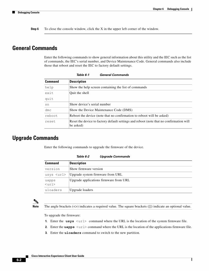
Chapter 6 Debugging ConsoleDebugging Console
Step 6 To close the console window, click the X in the upper left corner of the window.
General CommandsEnter the following commands to show general information about this utility and the IEC such as the list of commands, the IEC’s serial number, and Device Maintenance Code. General commands also include those that reboot and reset the IEC to factory default settings.
Table 6-1 General Commands
Upgrade CommandsEnter the following commands to upgrade the firmware of the device.
Table 6-2 Upgrade Commands
Note The angle brackets (<>) indicates a required value. The square brackets ([]) indicate an optional value.
To upgrade the firmware:
1. Enter the usys <url> command where the URL is the location of the system firmware file.
2. Enter the uapps <url> command where the URL is the location of the applications firmware file.
3. Enter the uloaders command to switch to the new partition.
Command Description
help Show the help screen containing the list of commands
exitquit
Quit the shell
sn Show device’s serial number
dmc Show the Device Maintenance Code (DMS)
reboot Reboot the device (note that no confirmation to reboot will be asked)
reset Reset the device to factory default settings and reboot (note that no confirmation will be asked)
Command Description
version Show firmware version
usys <url> Upgrade system firmware from URL
uapps <url>
Upgrade applications firmware from URL
uloaders Upgrade loaders
6-2Cisco Interactive Experience Client User Guide

Chapter 6 Debugging ConsoleDebugging Console
Debugging CommandsEnter the following commands to debug the device and view system statistics.
Warning Only run the debug command when troubleshooting the IEC. By default, debugging is turned off. When the debug command is turned on, every event is collected and sent to the IEM’s Events tab. The act of collecting and sending the events will use processing power and may impact the performance of the IEC. When you are not troubleshooting an issue on the IEC, make sure that debugging has been turned off by running the release command.
Table 6-3 Debugging Commands
Note The angle brackets (<>) indicates a required value. The square brackets ([]) indicate an optional value.
The figure below shows the output when the administrator entered the memstat command.
The figure below shows the output when the administrator entered the lsusb command.
Management CommandsEnter the following commands to manage the device.
Command Description
debug Switch the device to debug mode to generate log messages. Since this mode can generate many messages, it might compromise device performance. The device must be rebooted to start all the applications in debug mode.
release Switch the device to release mode to stop debug level logging. The device must be rebooted to start all the applications in release mode.
memstat Print memory statistics
cpustat Print CPU statistics
iostat Print I/O statistics
dstat Print local storage statistics
lsusb List connected USB devices
lsinput List connected input devices
httphead <url>
Send HEAD request to URL url. Response header will be printed.
ifconfig Show network interfaces configuration.
traceroute <host address>
Track the route packets taken from an IP network on their way to a given host.
nslookup <host fqdn>
Query Internet domain name servers to find out host's IP addresses.
6-3Cisco Interactive Experience Client User Guide

Chapter 6 Debugging ConsoleDebugging Console
Note These management commands were not designed to configure the device but to aid troubleshooting.
Table 6-4 Management Commands
Note The angle brackets (<>) indicates a required value. The square brackets ([]) indicate an optional value.
The figure below shows the output when the administrator entered the mng command.
Properties CommandsThe properties commands display and set values and parameters.
Table 6-5 Properties Commands
Command Description
mng Show IEM’s URL
setmng <url> Set IEM’s URL (note that the prefix will be ignored; it always should be ‘https’)
compression <on|off> Turn management protocol compression on or off
dload Load device’s profile from the IEM
diload Load device’s information (name and description) from the IEM
dsave Save device’s entire profile on the IEM
disave Save device’s information (name and description) on the IEM
esave Save events on the IEM (note that the saved events will be removed from the local event database)
dsync Save unsaved properties from the device’s profile on the IEM
pingmng Update device’s status on the IEM
ping <host> Ping the specified host
ismanaged Check if the device is in managed mode
isreg Check if the device is registered in the IEM
reg <account> <user> [password]
Register device in the IEM
ureg <user> [password] Unregister device in the IEM
Command Description
rm [wildcard] Remove persistent properties’ values (note that if no wildcard (‘*’) is provided, the entire storage will be cleared
ls [wildcard] List properties’ values
lsp <name> List persistent property’s value
6-4Cisco Interactive Experience Client User Guide
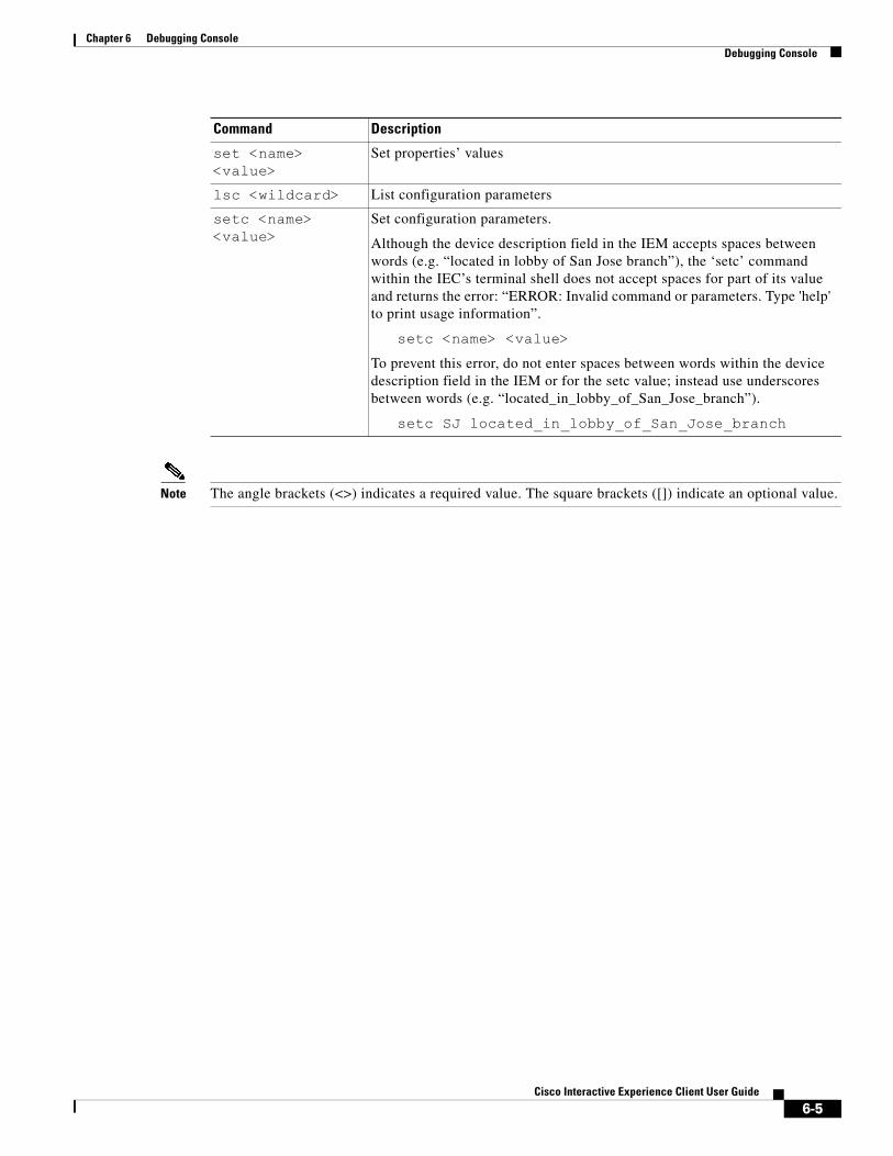
Chapter 6 Debugging ConsoleDebugging Console
Note The angle brackets (<>) indicates a required value. The square brackets ([]) indicate an optional value.
set <name> <value>
Set properties’ values
lsc <wildcard> List configuration parameters
setc <name> <value>
Set configuration parameters.
Although the device description field in the IEM accepts spaces between words (e.g. “located in lobby of San Jose branch”), the ‘setc’ command within the IEC’s terminal shell does not accept spaces for part of its value and returns the error: “ERROR: Invalid command or parameters. Type 'help' to print usage information”.
setc <name> <value>To prevent this error, do not enter spaces between words within the device description field in the IEM or for the setc value; instead use underscores between words (e.g. “located_in_lobby_of_San_Jose_branch”).
setc SJ located_in_lobby_of_San_Jose_branch
Command Description
6-5Cisco Interactive Experience Client User Guide

Chapter 6 Debugging ConsoleDebugging Console
6-6Cisco Interactive Experience Client User Guide

C H A P T E R 7
Locally Configuring the IECRevised: February 16, 2016
Chapter Overview
Note The Cisco IEC 4650 should be configured from the IEM by applying policies and configuring its profile. This chapter is only for configuration of a single IEC that is not connected to an IEM such as for demo purposes.
This chapter explains how to configure the Cisco IEC 4650 settings for demos or special deployment situations.
The topics in this chapter include the following:
• “Setting Stand-Alone Mode”
• “Audio Settings”
– “Specifying the Audio Input Device”
– “Specifying the Audio Output Device”
• “Date and Time Settings”
– “Setting the Date and Time”
– “Selecting the Time Zone”
• “Display Settings”
– “Adjusting the Rotation”
– “Selecting the Master Video Display”
• “Keyboard Settings”
– “Adjusting the Keyboard Parameters”
– “Specifying the Keyboard Layout”
• “Kiosk Settings”
– “Displaying the Navigational Panel and Content Title”
– “Displaying a Website using the Kiosk URL feature”
– “Specifying the Scrolling Mode”
7-1Cisco Interactive Experience Client User Guide
Chapter 7 Locally Configuring the IECSetting Stand-Alone Mode
• “Mouse Settings”
– “Changing the Mouse Button Order”
– “Changing the Mouse Acceleration and Threshold”
– “Displaying the Mouse Cursor”
Setting Stand-Alone ModeIf you will not use the Cisco IEM to manage the kiosk, configure the Cisco IEC 4650 using the stand-alone mode.
Warning If you have already registered a Cisco IEM account, choosing stand-alone will unregister that account.
Step 1 Press Ctrl-Alt-S to display the System Settings window.
Step 2 Click the System icon.
Step 3 If the Server tab is not displayed, click the Server tab.
Step 4 Enter the device name in the Device name field.
Step 5 Enter the device description in the Device Description field.
Step 6 Enter the device location in the Device Location field.
Step 7 Click the Switch to standalone button.
Step 8 Enter the account name in the Account field.
Step 9 Enter the user name in the User name field.
Step 10 Enter the password in the Password field. To verify that you entered the correct password, check the Show password check box to see the characters entered.
Step 11 Click Unregister.
Step 12 To exit the System window, click Close.
Step 13 In the System Settings window, click Reboot.
Audio SettingsThe Audio setting controls the input and output devices.
Specifying the Audio Input DeviceThe default setting for audio input is Analog. There are three types of input audio possible: Analog, Camera, and USB headset. If you want to change this setting, follow the steps below.
7-2Cisco Interactive Experience Client User Guide
Chapter 7 Locally Configuring the IECDate and Time Settings
Step 1 Press Ctrl-Alt-S to display the System Settings window.
Step 2 Click the Audio icon.
Step 3 If the input audio is an USB headset or a camera with an USB cable, connect the USB cable to an USB port on the Cisco IEC 4650. If the input audio is a camera with a TRS connector, connect the TRS connector to the microphone port or RS232 port on the Cisco IEC 4650.
Step 4 From the Input drop-down list, choose USB camera microphone or USB headset.
Step 5 When you complete the selections in this window, click Apply.
Step 6 To exit the Audio window, click Close.
Specifying the Audio Output DeviceThe default setting for audio output is Analog. The other options are HDMI, USB headset, and USB speaker.
Note The audio mode falls back to ‘Analog’ when the audio output is configured as ‘USB headset’ or ‘USB speaker’ but a USB headset or speaker is not connected to the IEC.
Step 1 Press Ctrl-Alt-S to display the System Settings window.
Step 2 Click the Audio icon.
Step 3 Connect the cable from the output device to a port (HDMI, USB, TRS headphone, or IR) on the Cisco IEC 4650.
Step 4 From the drop-down list, choose the type of output.
Step 5 Click Apply.
Step 6 To exit the Audio window, click Close.
Date and Time SettingsThe date, time, and time zone are automatically set by default but can be manually changed if they are incorrect.
Setting the Date and TimeFollow the steps below to change the date and time.
Step 1 Press Ctrl-Alt-S to display the System Settings window.
Step 2 Click the Date and Time icon.
Step 3 Click the Date & Time tab.
7-3Cisco Interactive Experience Client User Guide
Chapter 7 Locally Configuring the IECDisplay Settings
Step 4 To change the date and time, uncheck the Set date and time automatically check box.
Step 5 In the date field, enter the month, day, and year.
Step 6 In the time field, enter the hour, minute, and second.
Step 7 Click Apply to set the new date and time.
Step 8 To exit the Date and Time window, click Close.
Selecting the Time ZoneThe time zone is automatically determined by default. If the time zone is incorrect or you want to change it, follow the steps below.
Step 1 Press Ctrl-Alt-S to display the System Settings window.
Step 2 Click the Date and Time icon.
Step 3 .Click the Time Zone tab.
Step 4 From the Closest city drop-down list, choose a city.
Step 5 Click Apply to set the time zone.
Step 6 To exit the Date and Time window, click Close.
Display SettingsThere are two tabs in the Display settings window. The Information tab lists the display resolution, size, and depth. The General tab indicates the rotation of the display and type of master input used to connect the Cisco IEC 4650 to the video display.
Adjusting the RotationThe rotation is determined by the IEM policy that is applied. The rotation is set to Normal by default. To change the rotation in standalone mode, follow these steps:
Step 1 Press Ctrl-Alt-S to display the System Settings window.
Step 2 Click the Display icon.
Step 3 .Click the General tab.
Step 4 From the Rotation drop-down list, choose a setting (Normal, Clockwise, Counter Clockwise, or Upside Down) that will display the startup URL right-side up.
Step 5 Click Apply.
Step 6 To exit the Display window, click Close.
7-4Cisco Interactive Experience Client User Guide
Chapter 7 Locally Configuring the IECKeyboard Settings
Selecting the Master Video DisplayThe Master setting indicates the input method that is used to connect the video display to the Cisco IEC 4650 if more than one display has been connected. The two choices are VGA and HDMI. Choose the display connection that you want as the master video display by following these steps.
Step 1 Press Ctrl-Alt-S to display the System Settings window.
Step 2 Click the Display icon.
Step 3 Click the General tab.
Step 4 From the Master drop-down list, choose the type of connection used for the video display.
Step 5 Click Apply to set the master input.
Step 6 To exit the Display window, click Close.
Keyboard SettingsThe Keyboard settings can be changed. Follow these steps to view and change the keyboard settings.
Adjusting the Keyboard ParametersThe keyboard parameters are by default set to a 400 millisecond delay and at a rate of 35 per second. To change the parameters, follow these steps:
Step 1 Press Ctrl-Alt-S to display the System Settings window
Step 2 Click the Keyboard icon.
Step 3 Check the Enable keyboard repeat check box
Step 4 To change the delay, slide the delay bar, enter a number between 100 and 2000, or press the Up Arrow or Down Arrow to pick a value.
Step 5 To change the rate, slide the rate bar, enter a number between 1 and 50, or press the Up Arrow or Down Arrow to pick a value.
Step 6 When you complete the selections in this window, click Apply.
Step 7 To exit the Keyboard window, click Close.
Specifying the Keyboard LayoutKeyboards are available in different languages. The layout for keyboards can be different to accommodate the different characters in languages. In order for the Cisco IEC 4650 to work with your keyboard, make sure the correct language keyboard has been chosen.
The default keyboard is for the U.S.A. If the keyboard you are using is for a different country, follow these steps:
7-5Cisco Interactive Experience Client User Guide
Chapter 7 Locally Configuring the IECKiosk Settings
Step 1 Press Ctrl-Alt-S to display the System Settings window
Step 2 Click the Keyboard icon.
Step 3 Click the Layout tab of the Keyboard window.
Step 4 Find the country, language, and keyboard type within the Available layouts list.
Step 5 Click the Right Arrow to move that keyboard layout to the Configured layouts list.
Step 6 Click on the layout choice that you want to apply.
Note If the USA layout is not needed, you can move it to the Available layouts. Click the layout name and then click the Left Arrow.
Step 7 Click Apply to change the layout. Note that the Current layout at the bottom of the window has now changed.
Step 8 To exit the Keyboard window, click Close.
Kiosk SettingsIf you are using standalone mode, the Kiosk window allows you to modify how the kiosk display appears and interacts with the user. Once the Cisco IEC 4650 is restored to management mode, the Cisco IEM policy with override these local settings.
You can modify the following in the Kiosk settings screen:
• Title that appears on the top of the screen
• Navigational panel that appears on the top of the screen
• Web page that will display on the browser
Tip Only enter a URL if you are not using the IEM to manage the startup URL.
Note The URL should not be used for the Remote Expert.
Displaying the Navigational Panel and Content Title
Note If the navigational panel and content title are to be displayed on the kiosk, they should be configured in the Cisco IEM policy.
To display the navigational panel and the content title on the kiosk when in standalone mode, follow these steps:
Step 1 Press Ctrl-Alt-S to display the System Settings window
7-6Cisco Interactive Experience Client User Guide

Chapter 7 Locally Configuring the IECKiosk Settings
Step 2 Click the Kiosk icon.
Step 3 Check the Title check box to display a title.
Step 4 Check the Navigational panel check box to display the navigational panel.
Step 5 Click Apply.
Step 6 To exit the Kiosk window, click Close.
Step 7 In the System Settings window, click Reboot.
The navigational panel and content title now appear at the top of the kiosk display.
When the Navigational panel is enabled, the following buttons appear on the kiosk:
• Question/Help button
• Go back one page button
• Stop loading this page button
• Go to startup URL button
• Reload current page button
• Go forward one page button
• Print currently loaded page button
Displaying a Website using the Kiosk URL featureIf the Cisco IEC 4650 is in standalone mode, you can display a web page on the kiosk. This feature is available for demos of the unit or when the connection to the IEM has been lost temporarily and it is imperative for the monitor to display content while the connection is fixed.
Tip Only enter a URL if you are not using the IEM to manage the startup URL.
Note Remote Expert implementations should not use this feature.
Follow these steps to configure the Kiosk settings to display a web page:
Step 1 Press Ctrl-Alt-S to display the System Settings window
Step 2 Click the Kiosk icon.
Step 3 Enter the website address in the URL field.
Step 4 If the navigational panel should be displayed on the kiosk display, check the Navigational panel check box.
Step 5 Click Apply.
Step 6 To exit the Kiosk window, click Close.
Step 7 In the System Settings window, click Reboot.
7-7Cisco Interactive Experience Client User Guide

Chapter 7 Locally Configuring the IECMouse Settings
Specifying the Scrolling ModeIf scrolling is enabled, customers can scroll through the content on a page. When “Scroll bars” or “Kinetic scrolling” is chosen as the scrolling method, customers can use the mouse or their finger (if the screen is a touchscreen) to push the page content up, down, right, or left. When “Scroll panes” is the scrolling method, four panes appear on the screen to allow customers to push scroll bars up, down, right, or left. Follow these steps to set the scrolling mode:
Step 1 Press Ctrl-Alt-S to display the System Settings window.
Step 2 Click the Kiosk icon.
Step 3 Enter the website address in the URL field.
Step 4 From the Scrolling mode drop-down list, choose a scrolling mode.
Step 5 Click Apply.
Step 6 To exit the Kiosk window, click Close.
Step 7 In the System Settings window, click Reboot.
Mouse SettingsThe mouse settings can be changed. By default, the mouse has the following settings:
• Button order: Right handed
• Acceleration: 2.0
• Threshold: 4
• Mouse cursor: Hide
Changing the Mouse Button OrderFollow these steps to change the order of buttons on the mouse:
Step 1 Press Ctrl-Alt-S to display the System Settings window.
Step 2 Click the Mouse icon.
Step 3 To change the button order from right handed to left handed, click the Left handed radio button.
Step 4 Click Apply.
Step 5 To exit the Mouse window, click Close.
Step 6 In the System Settings window, click Reboot.
7-8Cisco Interactive Experience Client User Guide
Chapter 7 Locally Configuring the IECMouse Settings
Changing the Mouse Acceleration and ThresholdTo change the mouse acceleration and threshold settings, follow the steps below.
Step 1 Press Ctrl-Alt-S to display the System Settings window.
Step 2 Click the Mouse icon.
Step 3 To change the acceleration, slide the acceleration bar, enter a value between 0.0 and 20.0, or press the Up Arrow or Down Arrow to pick a value.
Step 4 To change the threshold, slide the threshold bar, enter a value between 0 and 20, or press the Up Arrow or Down Arrow to pick a value.
Step 5 When you complete the selections in this window, click Apply.
Step 6 To exit the Mouse window, click Close.
Step 7 In the System Settings window, click Reboot.
Displaying the Mouse CursorIf you want the mouse cursor to appear on the kiosk screen, follow these steps.
Step 1 Press Ctrl-Alt-S to display the System Settings window.
Step 2 Click the Mouse icon.
Step 3 From the drop-down list, choose Show to change the mouse cursor setting.
Step 4 To exit the Mouse window, click Close.
Step 5 In the System Settings window, click Reboot.
7-9Cisco Interactive Experience Client User Guide

Chapter 7 Locally Configuring the IECMouse Settings
7-10Cisco Interactive Experience Client User Guide

A P
Cisco In
P E D I N X A
Compatible PeripheralsRevised: February 16, 2016
Appendix OverviewThis appendix identifies which peripherals are compatible with the Cisco IEC 4650. Topics in this appendix include:
• “Compatible Peripherals”
– “Touchscreens and Touchscreen Overlays”
– “Monitors”
– “Remote Controls”
– “Wireless Keyboard and Mouse Combination”
– “Wired Mouse”
– “Wired Keyboards”
– “Analog Speakers”
– “Digital Speakers”
– “Analog Headsets”
– “Analog Microphones”
– “Digital Microphones”
– “Webcams”
– “Document Cameras”
– “Video Encoder Dongles”
– “Printers”
– “Optical Scanners”
– “Barcode Scanners”
– “Magnetic Card Readers”
– “HDMI Switches”
– “Wi-Fi: 3G USB Mobile Broadband”
• “Vendor Certification Guidelines”
A-1teractive Experience Client User Guide
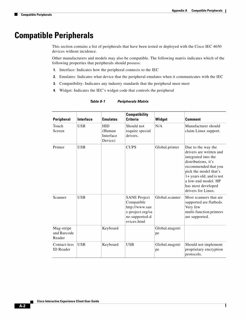
Appendix A Compatible PeripheralsCompatible Peripherals
Compatible PeripheralsThis section contains a list of peripherals that have been tested or deployed with the Cisco IEC 4650 devices without incidence.
Other manufacturers and models may also be compatible. The following matrix indicates which of the following properties that peripherals should possess:
1. Interface: Indicates how the peripheral connects to the IEC
2. Emulates: Indicates what device that the peripheral emulates when it communicates with the IEC
3. Compatibility: Indicates any industry standards that the peripheral must meet
4. Widget: Indicates the IEC’s widget code that controls the peripheral
Table 8-1 Peripherals Matrix
Peripheral Interface EmulatesCompatibility Criteria Widget Comment
Touch Screen
USB HID (Human Interface Device)
Should not require special drivers.
N/A Manufacturer should claim Linux support.
Printer USB CUPS Global.printer Due to the way the drivers are written and integrated into the distributions, it’s recommended that you pick the model that’s 1+ years old, and is not a low-end model. HP has most developed drivers for Linux.
Scanner USB SANE Project Compatible http://www.sane-project.org/sane-supported-devices.html
Global.scanner Most scanners that are supported are flatbeds. Very few multi-function printers are supported.
Mag-stripe and Barcode Reader
Keyboard Global.magstripe
Contact-less ID Reader
USB Keyboard USB Global.magstripe
Should not implement proprietary encryption protocols.
A-2Cisco Interactive Experience Client User Guide
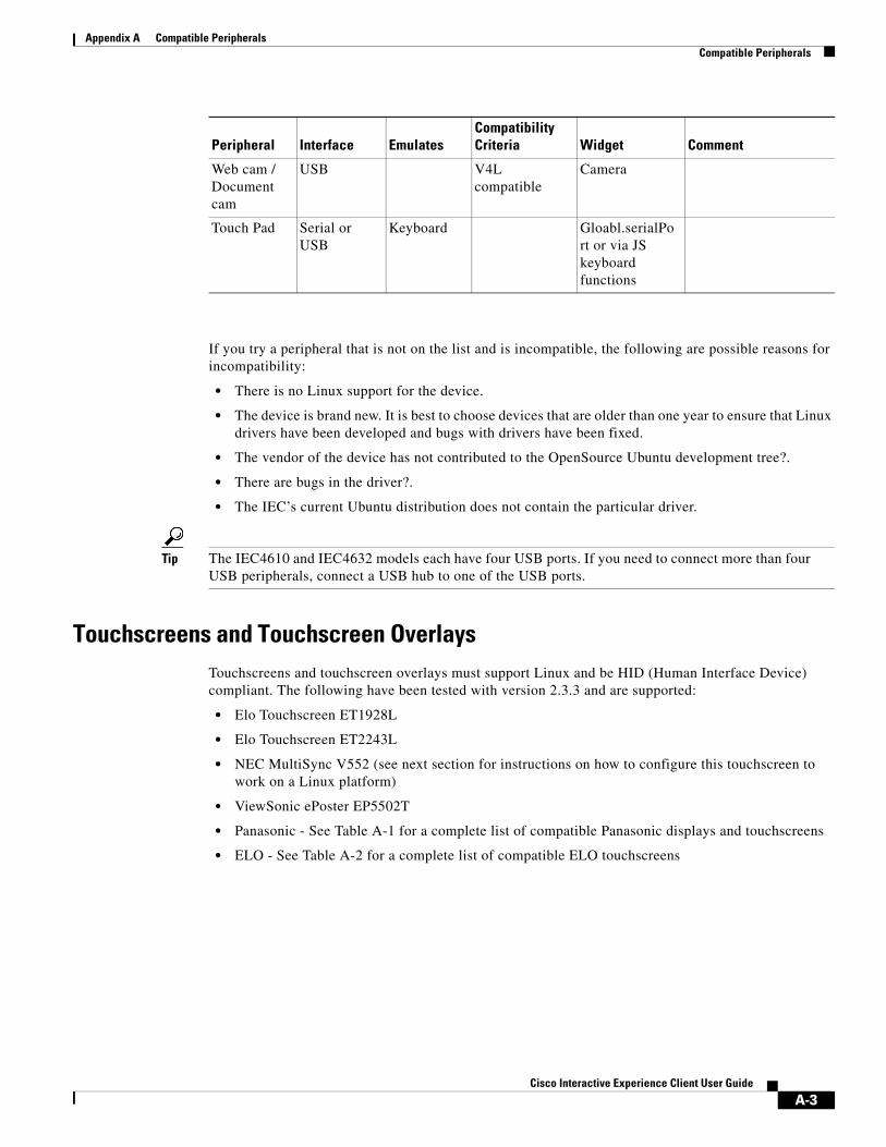
Appendix A Compatible PeripheralsCompatible Peripherals
If you try a peripheral that is not on the list and is incompatible, the following are possible reasons for incompatibility:
• There is no Linux support for the device.
• The device is brand new. It is best to choose devices that are older than one year to ensure that Linux drivers have been developed and bugs with drivers have been fixed.
• The vendor of the device has not contributed to the OpenSource Ubuntu development tree?.
• There are bugs in the driver?.
• The IEC’s current Ubuntu distribution does not contain the particular driver.
Tip The IEC4610 and IEC4632 models each have four USB ports. If you need to connect more than four USB peripherals, connect a USB hub to one of the USB ports.
Touchscreens and Touchscreen OverlaysTouchscreens and touchscreen overlays must support Linux and be HID (Human Interface Device) compliant. The following have been tested with version 2.3.3 and are supported:
• Elo Touchscreen ET1928L
• Elo Touchscreen ET2243L
• NEC MultiSync V552 (see next section for instructions on how to configure this touchscreen to work on a Linux platform)
• ViewSonic ePoster EP5502T
• Panasonic - See Table A-1 for a complete list of compatible Panasonic displays and touchscreens
• ELO - See Table A-2 for a complete list of compatible ELO touchscreens
Web cam / Document cam
USB V4L compatible
Camera
Touch Pad Serial or USB
Keyboard Gloabl.serialPort or via JS keyboard functions
Peripheral Interface EmulatesCompatibility Criteria Widget Comment
A-3Cisco Interactive Experience Client User Guide

Appendix A Compatible PeripheralsCompatible Peripherals
Table 8-2 Compatible Panasonic Touchscreens
Table 8-3 Compatible ELO Touchscreens
Application Family Device Model Numbers Device Category
Kiosk and Interactive Signage TH-42LF60 Display
TH-47LF60 Display
TH-55LF60 Display
TH-42LF6 Display
TH-47LF6 Display
TH-55LF6 Display
PPMT-IR42-EL Overlay
PPMT-IR47-EL Overlay
PPMT-IR55-EL Overlay
Passive Signage TH-42LFE7 Display
TH-65LFE7 Display
TH-47LFV5 Video Wall Display
TH-55LFV5 Video Wall Display
TH-55LFV50 Display
TH-47LFV70 Display
TH-55LFV70 Display
PT-DZ870 Projector
PT-DZ770 Projector
PT-DZ680 Projector
PT-DZ6700 Projector
Outdoor Passive Signage TH-47LFX6 Display
Family Name Type of Enclosure Size (Inches) Aspect Ratio Part Number
1215L Desktop 12 4:3 E432532
1215L Desktop 12 4:3 E991639
1247L Open Frame 12 4:3 E655204
1509L Desktop 15 16:9 E534869
1515L Desktop 15 4:3 E344320
1515L Desktop 15 4:3 E399324
1517L Desktop 15 4:3 E144246
1517L Desktop 15 4:3 E590483
1517L Desktop 15 4:3 E342516
1519L Desktop 15.6 16:9 E175716
1519L Desktop 15.6 16:9 E114849
A-4Cisco Interactive Experience Client User Guide

Appendix A Compatible PeripheralsCompatible Peripherals
1519L Desktop 15.6 16:9 E264492
1522L Desktop 15 4:3 E889598
1528L Desktop 15 4:3 E338457
1528L Desktop 15 4:3 E606958
1529L Desktop 15 4:3 E619005
1529L Desktop 15 4:3 E582772
1529L Desktop 15 4:3 E659634
1529L Desktop 15 4:3 E229149
1529L Desktop 15 4:3 E641269
1529L Desktop 15 4:3 E926109
1529L Desktop 15 4:3 E101984
1529L Desktop 15 4:3 E273617
1529L Desktop 15 4:3 E733714
1537L Open Frame 15 4:3 E731919
1537L Open Frame 15 4:3 E701210
1537L Open Frame 15 4:3 E512043
1541L Open Frame 15.6 16:9 E805638
1541L Open Frame 15.6 16:9 E606625
1715L Desktop 17 5:4 E603162
1715L Desktop 17 5:4 E719160
1717L Desktop 17 5:4 E649473
1717L Desktop 17 5:4 E679434
1717L Desktop 17 5:4 E179069
1717L Desktop 17 5:4 E227652
1729L Desktop 17 5:4 E763885
1729L Desktop 17 5:4 E274975
1729L Desktop 17 5:4 E461870
1729L Desktop 17 5:4 E629992
1739L Open Frame 17 5:4 E734455
1739L Open Frame 17 5:4 E607940
1739L Open Frame 17 5:4 E012584
1900L Desktop 19 16:10 E500662
1915L Desktop 19 5:4 E607608
1915L Desktop 19 5:4 E266835
1919L Desktop 18.5 16:9 E706956
1919L Desktop 18.5 16:9 E876321
1919L Desktop 18.5 16:9 E015447
Family Name Type of Enclosure Size (Inches) Aspect Ratio Part Number
A-5Cisco Interactive Experience Client User Guide

Appendix A Compatible PeripheralsCompatible Peripherals
Note If an Elo Touchscreen 2216 (1537L) is connected to an IEC in an account that is being exported, the import of that account’s XML file will fail. Garbage characters are produced in the name of the touchscreen field when using this Elo touchscreen. There are a number of workarounds if you need to
1919L Desktop 18.5 16:9 E120415
1919L Desktop 18.5 16:9 E803857
1928L Desktop 19 5:4 E522556
1928L Desktop 19 5:4 E935808
1928L Desktop 19 5:4 E188117
1928L Desktop 19 5:4 E897317
1937L Open Frame 19 5:4 E679610
1937L Open Frame 19 5:4 E896339
1938L Open Frame 19 16:10 E965017
1939L Open Frame 19 5:4 E779866
1939L Open Frame 19 5:4 E945445
1939L Open Frame 19 5:4 E215546
1940L Open Frame 19 16:9 E855244
2200L Desktop 22 16:10 E808372
2201L Desktop 22 16:9 E107766
2201L Desktop 22 16:9 E382790
2239L Open Frame 22 16:10 E846997
2240L Open Frame 22 16:10 E186354
2242L Open Frame 22 16:10 E667969
2243L Open Frame 22 16:9 E059181
2244L Open Frame 22 16:9 E469590
2400L Desktop 24 16:10 E100905
2400L Desktop 24 16:10 E964424
2400L Desktop 24 16:10 E178661
2639L Open Frame 26 16:9 E864190
3200L IDS 32 16:9 E994558
3239L Open Frame 32 16:9 E162387
4200L IDS 42 16:9 E841203
4200L IDS 42 16:9 E505459
4600L IDS 46 16:9 E960985
4600L IDS 46 16:9 E536712
5500L IDS 55 16:9 E053414
5500L IDS 55 16:9 E891542
Family Name Type of Enclosure Size (Inches) Aspect Ratio Part Number
A-6Cisco Interactive Experience Client User Guide
Appendix A Compatible PeripheralsCompatible Peripherals
import an account that contains IECs connected to this touchscreen: 1) Disconnect the monitor before exporting the account. 2) Delete the monitor block from exported XML and then import the file. 3) Delete the entire device block from exported XML and then import the file.
Configure the NEC MultiSync V552 to Work on a Linux Platform
To configure the NEC MultiSynch V552 touchscreen to work on a LINUX platform, follow these steps:
Step 1 Install the C.T.M. application on a WIN OS platform.
Step 2 Plug in the USB connector.
Step 3 Log into CTM.
Step 4 Navigate to Administrator > Functional Settings.
Step 5 Select the ProDrive radio button in the Protocol field.
Step 6 Configure the following values in the Communication field:
a. Configure the Touch Type as Single Touch.
b. Configure the Communications as Mouse.
c. Configure the Identification as Manual.
Step 7 Select the Operating System as Linux from the Touch Type field drop down menu.
Step 8 Select Back and then select Yes to save settings.
MonitorsAny monitor with a Mini DisplayPort or HDMI connector will work with 2.3.3. It is recommended that you use a 1920 x 1080 resolution.
Remote ControlsThe Cisco remote control that is supported for 2.3.3 is Cisco Remote Control IEP-IR-K9.
Other remote controls can also be used. See the “Non-Cisco Remote Controls” section in Appendix E for instructions on how to configure remote controls.
Wireless Keyboard and Mouse Combination
Note A wireless keyboard cannot be used during the installation of the IEC.
A wireless keyboard and mouse combination must be USB.
The following wireless keyboard and mouse combinations have been tested with 2.3.3 and are supported:
• Logitech USB wireless MK320
• Logitech USB wireless combo MK52
A-7Cisco Interactive Experience Client User Guide
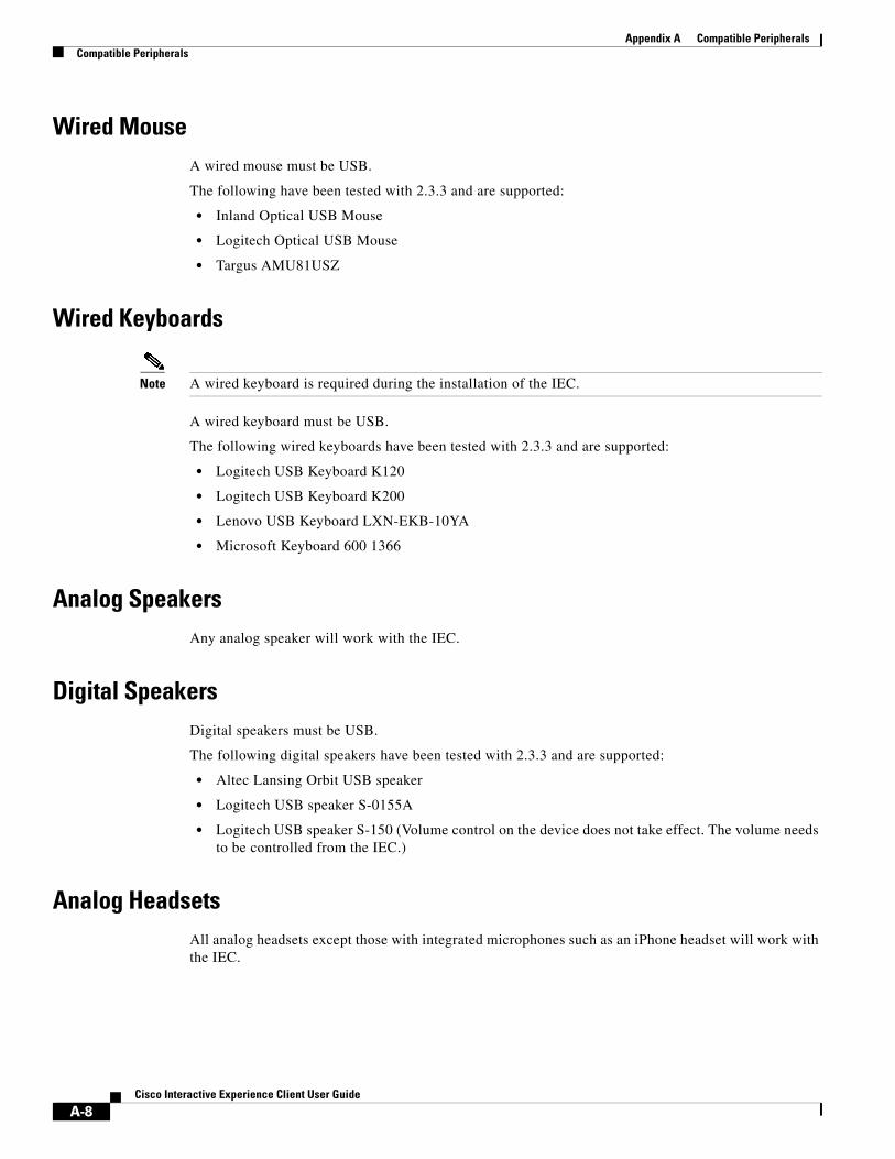
Appendix A Compatible PeripheralsCompatible Peripherals
Wired MouseA wired mouse must be USB.
The following have been tested with 2.3.3 and are supported:
• Inland Optical USB Mouse
• Logitech Optical USB Mouse
• Targus AMU81USZ
Wired Keyboards
Note A wired keyboard is required during the installation of the IEC.
A wired keyboard must be USB.
The following wired keyboards have been tested with 2.3.3 and are supported:
• Logitech USB Keyboard K120
• Logitech USB Keyboard K200
• Lenovo USB Keyboard LXN-EKB-10YA
• Microsoft Keyboard 600 1366
Analog SpeakersAny analog speaker will work with the IEC.
Digital SpeakersDigital speakers must be USB.
The following digital speakers have been tested with 2.3.3 and are supported:
• Altec Lansing Orbit USB speaker
• Logitech USB speaker S-0155A
• Logitech USB speaker S-150 (Volume control on the device does not take effect. The volume needs to be controlled from the IEC.)
Analog HeadsetsAll analog headsets except those with integrated microphones such as an iPhone headset will work with the IEC.
A-8Cisco Interactive Experience Client User Guide
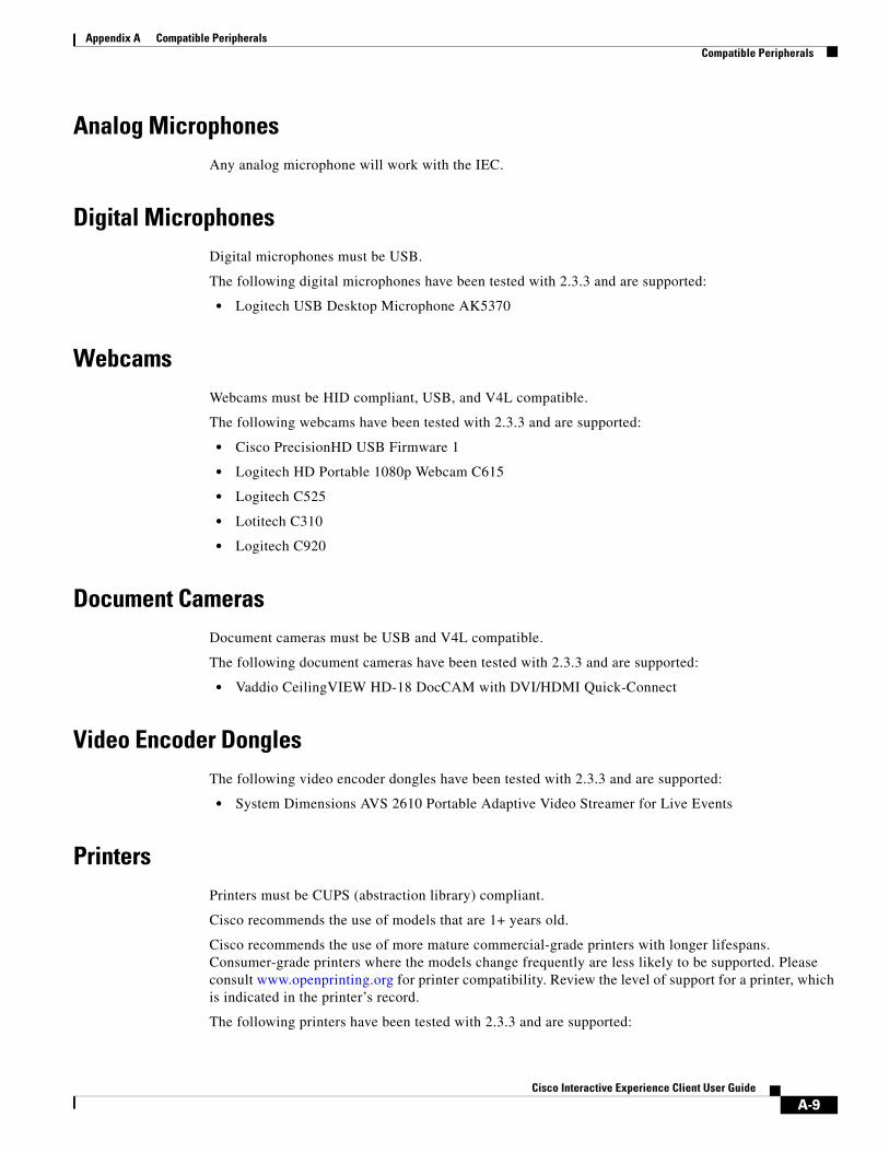
Appendix A Compatible PeripheralsCompatible Peripherals
Analog MicrophonesAny analog microphone will work with the IEC.
Digital MicrophonesDigital microphones must be USB.
The following digital microphones have been tested with 2.3.3 and are supported:
• Logitech USB Desktop Microphone AK5370
WebcamsWebcams must be HID compliant, USB, and V4L compatible.
The following webcams have been tested with 2.3.3 and are supported:
• Cisco PrecisionHD USB Firmware 1
• Logitech HD Portable 1080p Webcam C615
• Logitech C525
• Lotitech C310
• Logitech C920
Document CamerasDocument cameras must be USB and V4L compatible.
The following document cameras have been tested with 2.3.3 and are supported:
• Vaddio CeilingVIEW HD-18 DocCAM with DVI/HDMI Quick-Connect
Video Encoder DonglesThe following video encoder dongles have been tested with 2.3.3 and are supported:
• System Dimensions AVS 2610 Portable Adaptive Video Streamer for Live Events
PrintersPrinters must be CUPS (abstraction library) compliant.
Cisco recommends the use of models that are 1+ years old.
Cisco recommends the use of more mature commercial-grade printers with longer lifespans. Consumer-grade printers where the models change frequently are less likely to be supported. Please consult www.openprinting.org for printer compatibility. Review the level of support for a printer, which is indicated in the printer’s record.
The following printers have been tested with 2.3.3 and are supported:
A-9Cisco Interactive Experience Client User Guide
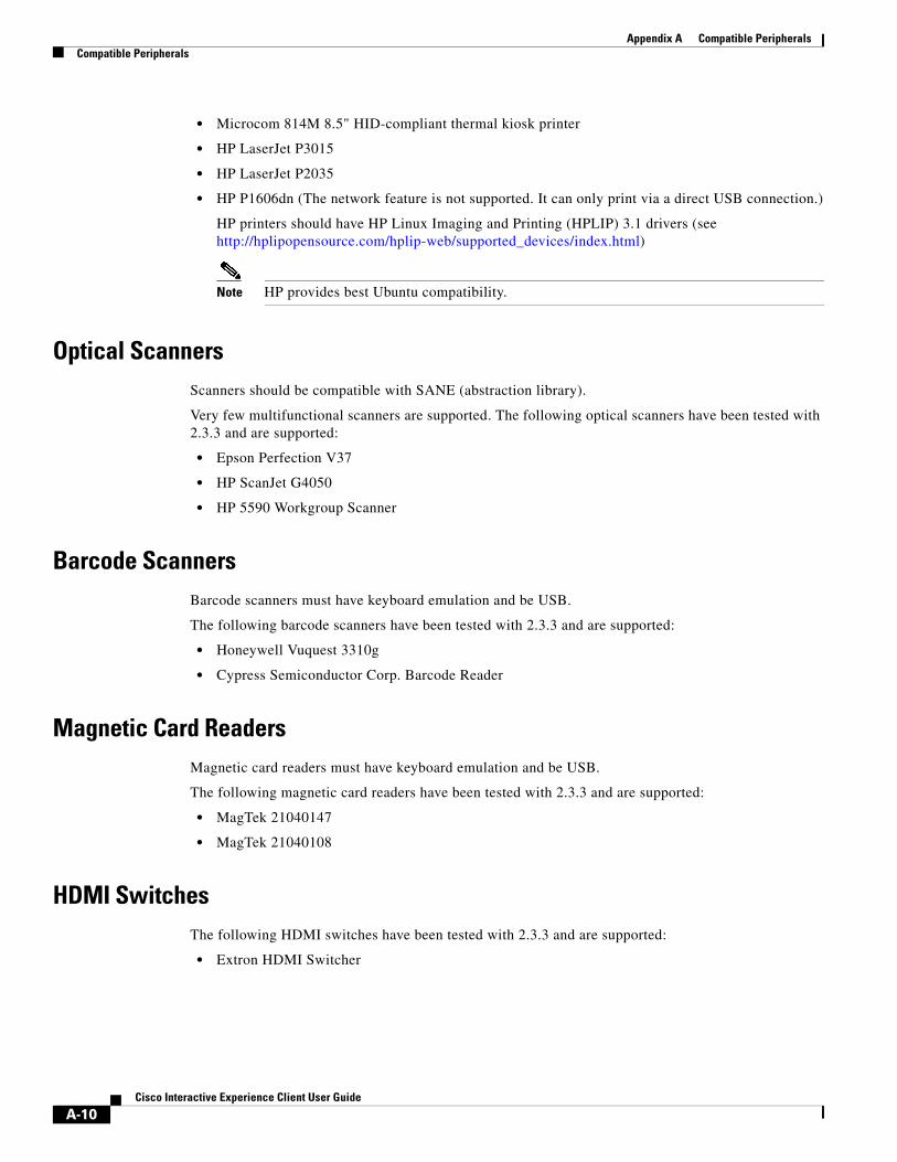
Appendix A Compatible PeripheralsCompatible Peripherals
• Microcom 814M 8.5" HID-compliant thermal kiosk printer
• HP LaserJet P3015
• HP LaserJet P2035
• HP P1606dn (The network feature is not supported. It can only print via a direct USB connection.)
HP printers should have HP Linux Imaging and Printing (HPLIP) 3.1 drivers (see http://hplipopensource.com/hplip-web/supported_devices/index.html)
Note HP provides best Ubuntu compatibility.
Optical ScannersScanners should be compatible with SANE (abstraction library).
Very few multifunctional scanners are supported. The following optical scanners have been tested with 2.3.3 and are supported:
• Epson Perfection V37
• HP ScanJet G4050
• HP 5590 Workgroup Scanner
Barcode ScannersBarcode scanners must have keyboard emulation and be USB.
The following barcode scanners have been tested with 2.3.3 and are supported:
• Honeywell Vuquest 3310g
• Cypress Semiconductor Corp. Barcode Reader
Magnetic Card ReadersMagnetic card readers must have keyboard emulation and be USB.
The following magnetic card readers have been tested with 2.3.3 and are supported:
• MagTek 21040147
• MagTek 21040108
HDMI SwitchesThe following HDMI switches have been tested with 2.3.3 and are supported:
• Extron HDMI Switcher
A-10Cisco Interactive Experience Client User Guide

Appendix A Compatible PeripheralsVendor Certification Guidelines
Wi-Fi: 3G USB Mobile BroadbandThe following Wi-Fi devices have been tested with 2.3.3 and are supported:
• Sierra Wireless Aircard 597E
• Cisco 881G Ethernet Sec Router w/3G B/U
Vendor Certification GuidelinesVendors of peripherals can perform self-certification based on the plug-and-play tests with the IEC.
The following table provides a comparison of the use of standard Linux drivers and custom Linux drivers with some of the peripherals.
Table 8-4 Standard Linux Drivers Versus Custom Linux Drivers
Touchscreens
Vendors who want to certify touchscreens should ensure the following:
• Vendors should confirm that the touchscreen is supported WITHOUT inserting special drivers.
• Vendors should claim LINUX support.
• Vendors should claim support of HID.
Webcams and Document Cameras
Vendors who want to certify webcams or document cameras should ensure the following:
• The cameras should be USB-based.
• The cameras should be V4L compatible.
Printers
Vendors who want to certify printers should ensure the following:
• Printers’ drivers should be CUPS (abstraction library) compliant.
• Models should be 1+ years old.
• Printers should be Ubuntu compatible.
Peripheral Standard Linux Driver Custom Linux Driver
Touchscreen HID-based, emulates mouse Requires custom drivers, closed
Magnetic card reader HID-based, emulates keyboard Closed, requires custom drivers, not visible to the browser application
Printer CUPS compliant, drivers are included in distribution
Non-CUPS compliant, drivers must be installed, cannot be handled by the configuration and printer widget in Cobra
Keypad Emulates keyboard, SR232 Closed to the system, cannot read from it from the application
A-11Cisco Interactive Experience Client User Guide
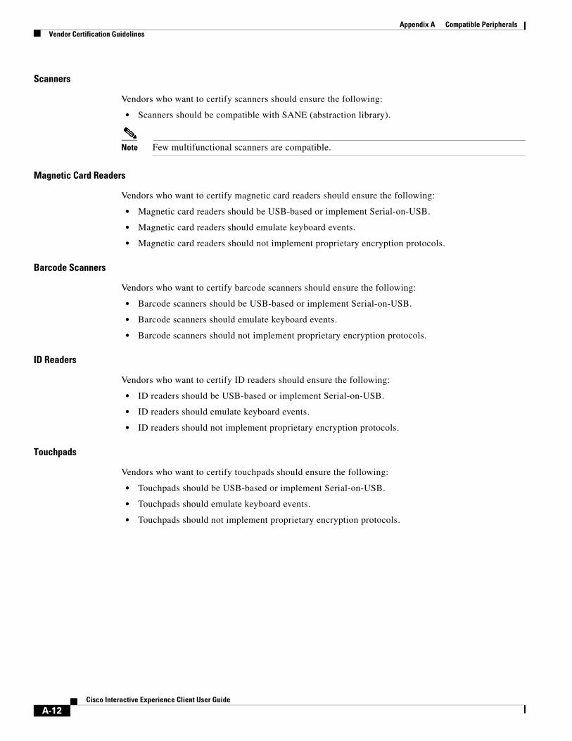
Appendix A Compatible PeripheralsVendor Certification Guidelines
Scanners
Vendors who want to certify scanners should ensure the following:
• Scanners should be compatible with SANE (abstraction library).
Note Few multifunctional scanners are compatible.
Magnetic Card Readers
Vendors who want to certify magnetic card readers should ensure the following:
• Magnetic card readers should be USB-based or implement Serial-on-USB.
• Magnetic card readers should emulate keyboard events.
• Magnetic card readers should not implement proprietary encryption protocols.
Barcode Scanners
Vendors who want to certify barcode scanners should ensure the following:
• Barcode scanners should be USB-based or implement Serial-on-USB.
• Barcode scanners should emulate keyboard events.
• Barcode scanners should not implement proprietary encryption protocols.
ID Readers
Vendors who want to certify ID readers should ensure the following:
• ID readers should be USB-based or implement Serial-on-USB.
• ID readers should emulate keyboard events.
• ID readers should not implement proprietary encryption protocols.
Touchpads
Vendors who want to certify touchpads should ensure the following:
• Touchpads should be USB-based or implement Serial-on-USB.
• Touchpads should emulate keyboard events.
• Touchpads should not implement proprietary encryption protocols.
A-12Cisco Interactive Experience Client User Guide
A P
Cisco Inte
P E N D I X B
PrintersRevised: February 16, 2016
Appendix OverviewThis appendix identifies how to implement printers at kiosks to allow end users to print documents.
Topics in this appendix include:
• “Printer Compatibility”
• “Printer Implementation”
– “global.printer Object”
– “PrintJob”
– “Example Usage of the global.printer Object”
– “Best Practices and Tips”
– “Testing the Printer Widget”
Printer CompatibilityRefer to Appendix A for a list of printers that have been tested with the IEC 4650.
Note Other printers may also be compatible.
Printer Implementation
global.printer ObjectThe global.printer object implements a printer interface which allows control of the printer connected to the IEC 4650 either locally or via the network. This object allows end users to print PDF files, images, plain text documents and HTML documents. Plain text and HTML documents must be UTF-8 encoded in order to be printed correctly.
B-1ractive Experience Client User Guide
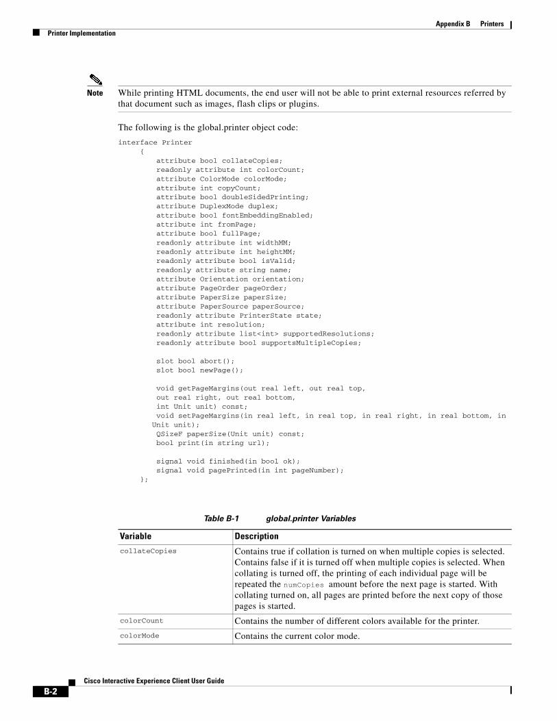
Appendix B PrintersPrinter Implementation
Note While printing HTML documents, the end user will not be able to print external resources referred by that document such as images, flash clips or plugins.
The following is the global.printer object code:
interface Printer {
attribute bool collateCopies; readonly attribute int colorCount; attribute ColorMode colorMode; attribute int copyCount; attribute bool doubleSidedPrinting; attribute DuplexMode duplex; attribute bool fontEmbeddingEnabled; attribute int fromPage; attribute bool fullPage; readonly attribute int widthMM; readonly attribute int heightMM; readonly attribute bool isValid; readonly attribute string name; attribute Orientation orientation; attribute PageOrder pageOrder; attribute PaperSize paperSize; attribute PaperSource paperSource; readonly attribute PrinterState state; attribute int resolution; readonly attribute list<int> supportedResolutions; readonly attribute bool supportsMultipleCopies; slot bool abort(); slot bool newPage(); void getPageMargins(out real left, out real top, out real right, out real bottom, int Unit unit) const; void setPageMargins(in real left, in real top, in real right, in real bottom, in Unit unit); QSizeF paperSize(Unit unit) const; bool print(in string url); signal void finished(in bool ok); signal void pagePrinted(in int pageNumber);
};
Table B-1 global.printer Variables
Variable Description
collateCopies Contains true if collation is turned on when multiple copies is selected. Contains false if it is turned off when multiple copies is selected. When collating is turned off, the printing of each individual page will be repeated the numCopies amount before the next page is started. With collating turned on, all pages are printed before the next copy of those pages is started.
colorCount Contains the number of different colors available for the printer.
colorMode Contains the current color mode.
B-2Cisco Interactive Experience Client User Guide
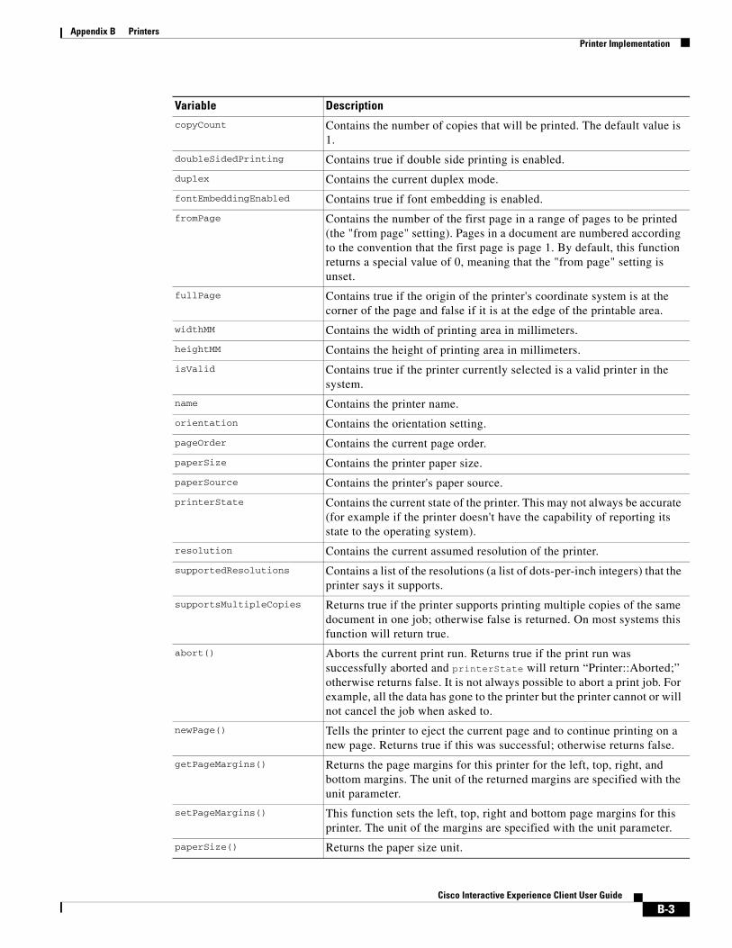
Appendix B PrintersPrinter Implementation
copyCount Contains the number of copies that will be printed. The default value is 1.
doubleSidedPrinting Contains true if double side printing is enabled.
duplex Contains the current duplex mode.
fontEmbeddingEnabled Contains true if font embedding is enabled.
fromPage Contains the number of the first page in a range of pages to be printed (the "from page" setting). Pages in a document are numbered according to the convention that the first page is page 1. By default, this function returns a special value of 0, meaning that the "from page" setting is unset.
fullPage Contains true if the origin of the printer's coordinate system is at the corner of the page and false if it is at the edge of the printable area.
widthMM Contains the width of printing area in millimeters.
heightMM Contains the height of printing area in millimeters.
isValid Contains true if the printer currently selected is a valid printer in the system.
name Contains the printer name.
orientation Contains the orientation setting.
pageOrder Contains the current page order.
paperSize Contains the printer paper size.
paperSource Contains the printer's paper source.
printerState Contains the current state of the printer. This may not always be accurate (for example if the printer doesn't have the capability of reporting its state to the operating system).
resolution Contains the current assumed resolution of the printer.
supportedResolutions Contains a list of the resolutions (a list of dots-per-inch integers) that the printer says it supports.
supportsMultipleCopies Returns true if the printer supports printing multiple copies of the same document in one job; otherwise false is returned. On most systems this function will return true.
abort() Aborts the current print run. Returns true if the print run was successfully aborted and printerState will return “Printer::Aborted;” otherwise returns false. It is not always possible to abort a print job. For example, all the data has gone to the printer but the printer cannot or will not cancel the job when asked to.
newPage() Tells the printer to eject the current page and to continue printing on a new page. Returns true if this was successful; otherwise returns false.
getPageMargins() Returns the page margins for this printer for the left, top, right, and bottom margins. The unit of the returned margins are specified with the unit parameter.
setPageMargins() This function sets the left, top, right and bottom page margins for this printer. The unit of the margins are specified with the unit parameter.
paperSize() Returns the paper size unit.
Variable Description
B-3Cisco Interactive Experience Client User Guide
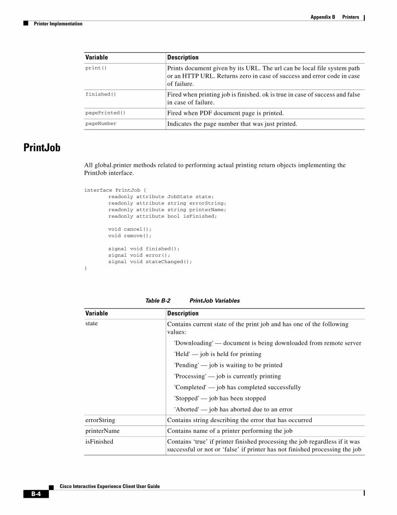
Appendix B PrintersPrinter Implementation
PrintJobAll global.printer methods related to performing actual printing return objects implementing the PrintJob interface.
interface PrintJob { readonly attribute JobState state; readonly attribute string errorString; readonly attribute string printerName; readonly attribute bool isFinished; void cancel(); void remove(); signal void finished(); signal void error(); signal void stateChanged();
}
Table B-2 PrintJob Variables
print() Prints document given by its URL. The url can be local file system path or an HTTP URL. Returns zero in case of success and error code in case of failure.
finished() Fired when printing job is finished. ok is true in case of success and false in case of failure.
pagePrinted() Fired when PDF document page is printed.
pageNumber Indicates the page number that was just printed.
Variable Description
Variable Description
state Contains current state of the print job and has one of the following values:
'Downloading' — document is being downloaded from remote server
'Held' — job is held for printing
'Pending' — job is waiting to be printed
'Processing' — job is currently printing
'Completed' — job has completed successfully
'Stopped' — job has been stopped
'Aborted' — job has aborted due to an error
errorString Contains string describing the error that has occurred
printerName Contains name of a printer performing the job
isFinished Contains ‘true’ if printer finished processing the job regardless if it was successful or not or ‘false’ if printer has not finished processing the job
B-4Cisco Interactive Experience Client User Guide
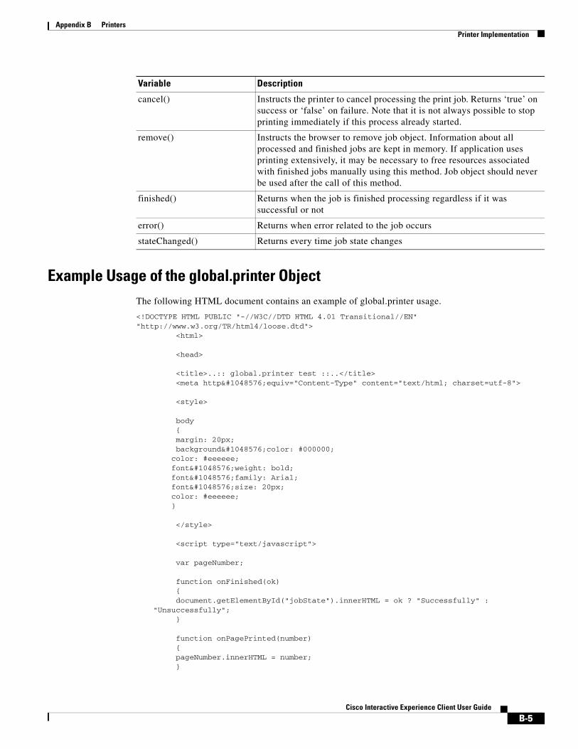
Appendix B PrintersPrinter Implementation
Example Usage of the global.printer ObjectThe following HTML document contains an example of global.printer usage.
<!DOCTYPE HTML PUBLIC "-//W3C//DTD HTML 4.01 Transitional//EN" "http://www.w3.org/TR/html4/loose.dtd">
<html> <head> <title>..:: global.printer test ::..</title> <meta http􀀀equiv="Content-Type" content="text/html; charset=utf-8"> <style> body { margin: 20px; background􀀀color: #000000; color: #eeeeee; font􀀀weight: bold; font􀀀family: Arial; font􀀀size: 20px; color: #eeeeee; } </style> <script type="text/javascript"> var pageNumber; function onFinished(ok) { document.getElementById("jobState").innerHTML = ok ? "Successfully" : "Unsuccessfully"; } function onPagePrinted(number) { pageNumber.innerHTML = number; }
cancel() Instructs the printer to cancel processing the print job. Returns ‘true’ on success or ‘false’ on failure. Note that it is not always possible to stop printing immediately if this process already started.
remove() Instructs the browser to remove job object. Information about all processed and finished jobs are kept in memory. If application uses printing extensively, it may be necessary to free resources associated with finished jobs manually using this method. Job object should never be used after the call of this method.
finished() Returns when the job is finished processing regardless if it was successful or not
error() Returns when error related to the job occurs
stateChanged() Returns every time job state changes
Variable Description
B-5Cisco Interactive Experience Client User Guide

Appendix B PrintersPrinter Implementation
function init() { document.getElementById("name").innerHTML = global.printer.name; document.getElementById("resolution").innerHTML = global.printer.resolution; document.getElementById("state").innerHTML = global.printer.state; pageNumber = document.getElementById("pageNumber"); global.printer.finished.connect(onFinished); global.printer.pagePrinted.connect(onPagePrinted); // global.printer.print("http://www2.lauterbach.com/doc/rtosqnx.pdf"); // global.printer.print("http://is1.vladstudio.com/jpg_low/1600x1200/vladstudio_gecko_1600x1200 .jpg"); global.printer.print("http://lenta.ru/news/2011/09/20/c27j/"); } </script> </head> <body onload="init()"> <table cellpadding="2" cellspacing="0" border="1" align="center" width="50%"> <tr> <td>Printer name</td> <td id="name"></td> </tr> <tr> <td>Resolution</td> <td id="resolution"></td> </tr> <tr> <td>State</td> <td id="state"></td> </tr> <tr> <td>Page printed</td> <td id="pageNumber"></td> </tr> <tr> <td>Job finished</td> <td id="jobState"></td> </tr> </table> </body>
</html>
Best Practices and Tips• Make sure to have the location of the file as a URL.
• Change the URL in the above HTML to print another file.
• Copy the above contents to an HTML file and transfer the file to a web server from where it can be accessed.
B-6Cisco Interactive Experience Client User Guide

Appendix B PrintersPrinter Implementation
• The printer must be connected to the IEC. Reboot the IEC after connecting the printer.
Testing the Printer WidgetThere are two ways to test the printer widget:
1. Using the policy:
1. Create a policy with startup URL as the URL of the printer HMTL and apply the policy
As a result, the IEC boots up with the printer policy loaded.
2. Using the Kiosk menu:
1. On the IEC, press Ctl + Alt + S and then choose Kiosk
2. Enter the printer widget URL
3. Reboot the IEC
As a result, the IEC boots up with the printer URL loaded.
B-7Cisco Interactive Experience Client User Guide

Appendix B PrintersPrinter Implementation
B-8Cisco Interactive Experience Client User Guide

A P
Cisco In
P E N D I X C
Optical ScannersRevised: February 16, 2016
Appendix OverviewAn optical scanner can be connected to the IEC to allow end users to scan a document at the kiosk.
This appendix explains how to implement optical scanners connected to the IECs.
Topics in this appendix include:
• “Optical Scanner Compatibility”
• “Optical Scanner Implementation”
– “global.scanner Object”
– “Best Practices and Tips”
– “Testing the Scanner Widget”
Optical Scanner CompatibilityRefer to Appendix A for the list of optical scanners that have been tested with the IEC.
Note Other scanner models may also be compatible.
Optical Scanner Implementation
global.scanner ObjectThe global.scanner object implements an interface for optical scanners allowing an application displayed on a kiosk to scan and manipulate a document. The scanner library used is from SANE and the list of compatible devices can be found here: http://www.sane-project.org/sane-supported-devices.html
The global.scanner object code is:
interface Scanner
C-1teractive Experience Client User Guide

Appendix C Optical ScannersOptical Scanner Implementation
{ attribute uint dpiX; attribute uint dpiY; attribute bool color; attribute string source; readonly attribute List<String> devices; readonly attribute List<String> sources; readonly attribute string lastError; readonly attribute string base64Data;
readonly attribute bool busy;
void setCurrentScanner(in string deviceName);
signals: void finished(); void error(out string error);
slots: start(); stop(); shutdown();};
Table C-1 global.scanner Object Variables
Variable Description
dpiX DPI X of the selected scanner
dpiY DPI Y of the selected scanner
color Is selected scanner in color mode
source Document source
devices List of available scanners
sources List of available document sources
lastError Last error occurred
base64Data Scanned image as base64 JPEG data
busy Check if the scanner is busy
setCurrentScanner(in string deviceName) Set the current scanner to use. You need to call this method before scanning.
finished() The scanner has finished scanning
error(out string error) An error has occurred
start() Start scanning from the selected scanner and document source
stop() Stop scanning
shutdown() Shutdown scanning subsystem and reset all internal caches
C-2Cisco Interactive Experience Client User Guide

Appendix C Optical ScannersOptical Scanner Implementation
Best Practices and Tips• Make sure to have the location of the file as a URL.
• Copy the above contents to an HTML file and transfer the file to a web server from where it can be accessed.
• The scanner must be connected to the IEC. Reboot the IEC after connecting the scanner.
Testing the Scanner WidgetThere are two ways to test the scanner widget:
1. Using the policy:
1. Create a policy with startup URL as the URL of the scanner HTML and apply the policy
As a result, the IEC boots up with the scanner policy loaded.
2. Using the Kiosk menu:
1. On the IEC, press Ctl + Alt + S and then choose Kiosk
2. Enter the scanner widget URL
3. Reboot the IEC
As a result, the IEC boots up with the scanner URL loaded.
C-3Cisco Interactive Experience Client User Guide

Appendix C Optical ScannersOptical Scanner Implementation
C-4Cisco Interactive Experience Client User Guide

A P P E N D I X D
Magnetic Card Readers and Barcode ScannersRevised: February 16, 2016
Appendix OverviewThis appendix explains how to implement magnetic card readers and barcode scanners to allow end users to swipe their credit cards, customer loyalty cards, or gift cards or scan a barcode on a product.
Topics in this appendix include:
• “Magnetic Card Reader and Barcode Scanner Compatibility”
• “Magnetic Card Reader and Barcode Scanner Implementation”
– “Magnetic Card Reader or Barcode Scanner Name”
– “global.magstripe Object”
– “Implement the global.magstripe Object”
Magnetic Card Reader and Barcode Scanner CompatibilityHID or keyboard emulation-type magnetic card readers and barcode scanners are supported by IEC 4650 devices. Refer to Appendix A for a list of magnetic card readers and barcode scanners that have been tested with the IEC 4650.
Magnetic Card Reader and Barcode Scanner ImplementationTo enable the magnetic card reader or barcode scanner, you will perform the following:
1. Retrieve the name of the peripheral that the IEC recognizes
2. Replace the deviceName variable in the global.magstripe object with the name of the peripheral that the IEC recognizes
3. Implement the global.magstripe object in your application
4. Configure the key and value in the device’s profile or an applied property in the IEM
D-1Cisco Interactive Experience Client User Guide

Appendix D Magnetic Card Readers and Barcode ScannersMagnetic Card Reader and Barcode Scanner Implementation
Magnetic Card Reader or Barcode Scanner NameYou need the exact name of the card reader or barcode scanner by which the IEC recognizes the peripheral. Follow these steps to retrieve that name:
Step 1 Plug the magnetic card reader or barcode scanner into the USB port of the IEC.
Step 2 Reboot the IEC so that the IEC will recognize the new peripheral.
Step 3 Run the lsinput command at the shell prompt to get a list of connected input devices.
Note Alternatively, you can get the name from the Cisco Interactive Experience Manager (IEM). Go to the device and click the Status tab.
Step 4 Find the name of the magnetic card reader or barcode scanner. In the example below, the magnetic card reader is shown in red:
Virtual core pointer id=2[master pointer (3)]Virtual core XTEST pointer id=4[slave pointer (2)]Microsoft Microsoft® Digital Media Keyboardid=12[slave pointer (2)]Filtered Elo TouchSystems, Inc. Elo TouchSystems 2700 IntelliTouch(r) USB Touchid=14[slave pointer (2)]MCE IR Keyboard/Mouse (ite-cir) id=15[slave pointer (2)]Elo TouchSystems, Inc. Elo TouchSystems 2700 IntelliTouch(r) USB Touchmonitor Interfaceid=9[slave pointer (2)]
Virtual core keyboard id=3[master keyboard (2)]Virtual core XTEST keyboard id=5[slave keyboard (3)]Power Button id=6[slave keyboard (3)]Video Bus id=7[slave keyboard (3)]Power Button id=8[slave keyboard (3)]PWC snapshot button id=10[slave keyboard (3)]Microsoft Microsoft® Digital Media Keyboardid=11[slave keyboard (3)]Mag-Tek USB Swipe Reader id=13[slave keyboard (3)]ACPI Virtual Keyboard Device id=16[slave keyboard (3)]ITE8704 CIR transceiver id=17[slave keyboard (3)]
Step 5 Replace the deviceName variable in the global.magstripe object with the name of the peripheral that the IEC recognizes.
Step 6 In the device’s profile or a property applied to that device within the IEM, configure the application data property with “barcode.scanner” or “magstripe.scanner” for the key and the name of the peripheral that the IEC recognizes for the value.
Step 7 Click Ok.
Step 8 Click Apply.
global.magstripe ObjectThe global.magstripe object is a widget that provides an interface to magnetic card readers or barcode scanners.
D-2Cisco Interactive Experience Client User Guide

Appendix D Magnetic Card Readers and Barcode ScannersMagnetic Card Reader and Barcode Scanner Implementation
In the case of a card reader, the widget reacts to a scan of a card and returns the value of the data that is recorded on the magnetic stripe. For credit cards, the data returned is typically cardholder’s name, card number, and expiration date. The widget returns the data in an unparsed form, so it is the responsibility of the developer to decrypt if necessary and parse the data.
For a barcode reader, the widget registers a scanned event and returns the string that represents the barcode.
The global.magstripe object code is:
interface Magstripe { void open(in string deviceName); void close();
signals:void opened(); void scanning(); void scanned(out string data); void error(out string error);}
Table D-1 global.magstripe Object Variables
Implement the global.magstripe Object
Step 1 Open your application’s code.
Step 2 Insert the global.magstripe object code.
Step 3 Replace the deviceName variable with the name of the device that you retrieved from the IEC.
Variable Description
open(in string deviceName) Open the device for reading data. If deviceName is not empty, use this device name, and browser.magstripe.scanner property otherwise.
close() Close the device.
opened() The device has been open successfully.
scanning() The device has started data scanning.
scanned(out string data) The device has finished scanning, read the scanned data from deviceName.
error(out string error) Error has occurred.
D-3Cisco Interactive Experience Client User Guide

Appendix D Magnetic Card Readers and Barcode ScannersMagnetic Card Reader and Barcode Scanner Implementation
D-4Cisco Interactive Experience Client User Guide
A P P E N D I X E
Infrared Remote ControlsRevised: February 16, 2016
Appendix OverviewAn Infrared (IR) Cisco Remote Control can be connected to the Cisco IIEC 4650 device so that the end user can control applications and remote playback without touching the screen or using a mouse.
This appendix explains how to configure applications to allow use of either a Cisco and non-Cisco remote control.
Topics in this appendix include:
• “Cisco Remote Control IEP-IR-K9”
– “Battery”
– “Infrared Sensor”
– “Remote Control Buttons”
– “Remote Control Implementation”
– “global.ir Object”
– “Usage of global.ir Object”
• “Non-Cisco Remote Controls”
– “Using the IEM’s IR Configuration Property”
– “Using the API”
Cisco Remote Control IEP-IR-K9The Cisco Remote Control IEP-IR-K9 is the remote control model that is supported with the IEC.
Battery
Warning Lithium Batteries are used in this module. Do not try to charge, discharge, or replace these batteries.
E-1Cisco Interactive Experience Client User Guide
Appendix E Infrared Remote ControlsCisco Remote Control IEP-IR-K9
The Cisco remote control is battery-powered. It uses a standard, 3V CR2025 lithium battery, manufactured by a well-known supplier such as Panasonic or Toshiba. The name of the actual manufacturer is etched into the face of the battery.
When the battery loses its charge or when you remove the battery, the remote control will not work until the battery is replaced.
You should always recycle or dispose of the battery in accordance with:
• Its manufacturer guidelines.
• Regulations in your locale for disposal and recycling.
Note Remote control settings are not lost when you remove or replace the battery.
To replace the battery in the remote control, follow these steps:
Step 1 Place the remote control on a flat surface, button-side down.
Step 2 To unlock the battery clip and remove it, pinch the locking mechanism and slide the clip out of the remote control.
Step 3 To remove the old battery from the clip, pivot the battery so that it touches only the opening of the clip.
Step 4 Insert a new battery so that positive charge (+) symbols are visible simultaneously on the battery and the clip.
Step 5 Slide the clip back in to the remote control.
Infrared SensorThe IEC is equipped with an infrared (IR) sensor that receives, recognizes, and reacts to the signals from this Cisco remote control.
The way that you mount an IEC can limit how well it responds to these signals. The mounting method might block the IR sensor.
It is recommended to use an IR extender with the remote control. With the IR extender, the range of the remote control is approximately up to 15 feet (4.57m).
The IR sensor of the extender (or the IR sensor of the IEC if you are not using the extender) must be in the line of sight of the end user. The remote control will not work if the IR sensor is behind the touchscreen or blocked by another peripheral.
Note Please ensure that you are using a suitable IR cable that was suggested by your Cisco distributor or importer source.
Remote Control ButtonsAll the buttons can be programmed. The functions listed in the tables below are standard functions for the keys.
E-2Cisco Interactive Experience Client User Guide
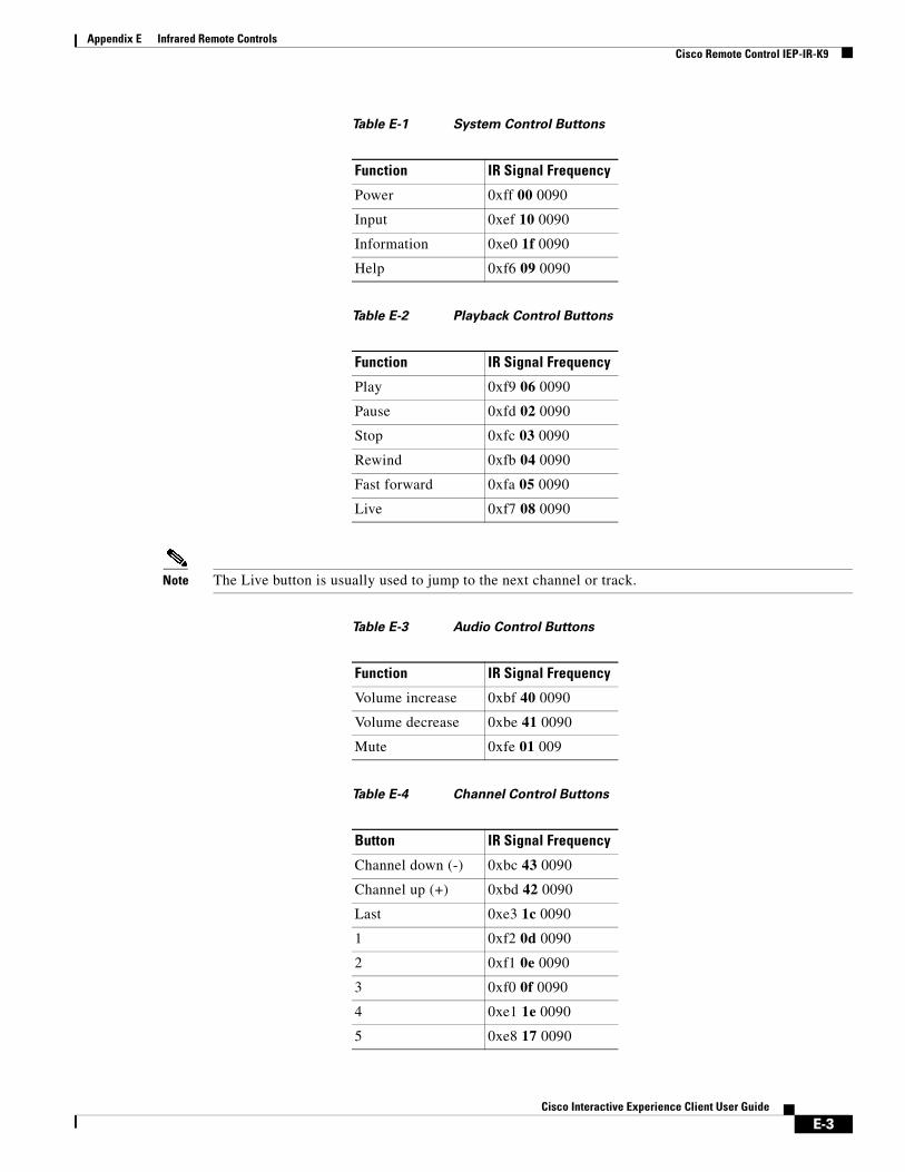
Appendix E Infrared Remote ControlsCisco Remote Control IEP-IR-K9
Table E-1 System Control Buttons
Table E-2 Playback Control Buttons
Note The Live button is usually used to jump to the next channel or track.
Table E-3 Audio Control Buttons
Table E-4 Channel Control Buttons
Function IR Signal Frequency
Power 0xff 00 0090
Input 0xef 10 0090
Information 0xe0 1f 0090
Help 0xf6 09 0090
Function IR Signal Frequency
Play 0xf9 06 0090
Pause 0xfd 02 0090
Stop 0xfc 03 0090
Rewind 0xfb 04 0090
Fast forward 0xfa 05 0090
Live 0xf7 08 0090
Function IR Signal Frequency
Volume increase 0xbf 40 0090
Volume decrease 0xbe 41 0090
Mute 0xfe 01 009
Button IR Signal Frequency
Channel down (-) 0xbc 43 0090
Channel up (+) 0xbd 42 0090
Last 0xe3 1c 0090
1 0xf2 0d 0090
2 0xf1 0e 0090
3 0xf0 0f 0090
4 0xe1 1e 0090
5 0xe8 17 0090
E-3Cisco Interactive Experience Client User Guide

Appendix E Infrared Remote ControlsCisco Remote Control IEP-IR-K9
Table E-5 Menu Control Buttons
Table E-6 Guide Control Buttons
Table E-7 Soft Keys
The following is an example of programming for the remote control in an application:
if(!filterIR){filterIR = true;document.getElementById("trace").innerHTML = "IR pressed key code: "+key+" ("+skey+")";switch(skey){case "play":
6 0xe7 18 0090
7 0xe6 19 0090
8 0xe5 1a 0090
9 0xe4 1b 0090
0 0xe2 1d 0090
Function IR Signal Frequency
Menu 0xb8 47 0090
Up 0xea 15 0090
Left 0xec 13 0090
OK 0xed 12 0090
Right 0xeb 14 0090
Down 0xe9 16 0090
Function IR Signal Frequency
Guide 0xf5 0a 0090
Page up 0xea 15 0090
Page down 0xf3 0c 0090
Exit 0xee 11 0090
Button IR Signal Frequency
A 0xa9 56 0090
B 0xaf 50 0090
C 0xad 52 0090
D 0xab 54 0090
Button IR Signal Frequency
E-4Cisco Interactive Experience Client User Guide

Appendix E Infrared Remote ControlsCisco Remote Control IEP-IR-K9
HUD("play");playVideo();break;case "pause":HUD("pause");togglePause();break;case "fastforward":HUD("fwd");playNextTrack();break;case "rewind":HUD("rewind");playPrevTrack()break;case "stop":HUD("stop");stopVideo();break;case "right":HUD("right");selectNext();break;case "left":HUD("left");selectPrevious();break;case "okay":HUD("play");playSelected();break;case "power":window.location = "index.html";default:break;}irFilterTimeout = setTimeout(function(){filterIR=false}, 750);}
Remote Control ImplementationThe IR port is active by default. No additional configuration is required.
You will need to embed the global.ir object into your application code in order for your applications to perform the expected action when the end user presses a button on the remote control.
global.ir Object The global.ir object implements the IR interface. It allows an application to receive signals from the infrared remote control.
The global.ir object code is:
interface Ir { readonly attribute string lastError; List <String> availableControls() const; bool setCurrentControl(in string device);
E-5Cisco Interactive Experience Client User Guide
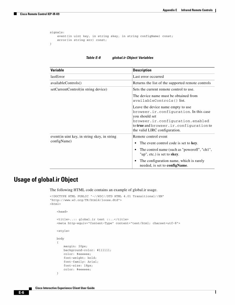
Appendix E Infrared Remote ControlsCisco Remote Control IEP-IR-K9
signals: event(in uint key, in string skey, in string configName) const; error(in string err) const;}
Table E-8 global.ir Object Variables
Usage of global.ir ObjectThe following HTML code contains an example of global.ir usage.
<!DOCTYPE HTML PUBLIC "-//W3C//DTD HTML 4.01 Transitional//EN" "http://www.w3.org/TR/html4/loose.dtd"><html>
<head>
<title>..:: global.ir test ::..</title><meta http-equiv="Content-Type" content="text/html; charset=utf-8">
<style>
body{
margin: 20px;background-color: #111111;color: #eeeeee;font-weight: bold;font-family: Arial;font-size: 18px;color: #eeeeee;
}
Variable Description
lastError Last error occurred
availableControls() Returns the list of the supported remote controls
setCurrentControl(in string device) Sets the current remote control to use.
The device name must be obtained from availableControls() list.
Leave the device name empty to use browser.ir.configuration. In this case you should set browser.ir.configuration.enabled to true and browser.ir.configuration to the valid LIRC configuration.
event(in uint key, in string skey, in string configName)
Remote control event
• The event control code is set to key.
• The control name (such as "poweroff", "ch1", "up", etc.) is set to skey.
• The configuration name, which is rarely needed, is set to configName.
E-6Cisco Interactive Experience Client User Guide

Appendix E Infrared Remote ControlsCisco Remote Control IEP-IR-K9
</style>
<script type="text/javascript">
var errorId;var eventId;var controlId;var timer;
var remoteInfo;
function init(){
errorId = document.getElementById("error");eventId = document.getElementById("event");controlId = document.getElementById("control");remoteInfo = document.getElementById("remoteInfo");
global.ir.error.connect(onError); writeLog("onError() connected to signal global.ir.error");global.ir.event.connect(onEvent); writeLog("onEvent() connected to signal global.ir.event");
try{
var irconf = global.registry.value("browser.ir.configuration");
if(irconf=='<binary mimeType="text/plain"><![CDATA[]]></binary>' || irconf==''){
// set default remote as current.//global.ir.setCurrentControl(defaultRemote);remoteInfo.innerHTML = "Default (Cisco remote control)";writeLog("Default remote control configuration applied.");
} else{global.ir.setCurrentControl();remoteInfo.innerHTML = "* user defined remote control *";writeLog("User defined remote control configuration applied.");
}} catch(ex){
writeLog("Exception: "+ex);}
}
function deinit(){
global.ir.error.disconnect(onError);global.ir.event.disconnect(onEvent);
}
function onError(err){
errorId.innerHTML = err;writeLog("onError(): "+err);
}
function onEvent(key, skey, config){
eventId.innerHTML = "" + key + ' ' + skey + ' ' + config;writeLog("onEvent(): "+key + " " + skey + " " + config);
clearTimeout(timer);timer = setTimeout(function() { eventId.innerHTML = ""; }, 750);
}
E-7Cisco Interactive Experience Client User Guide
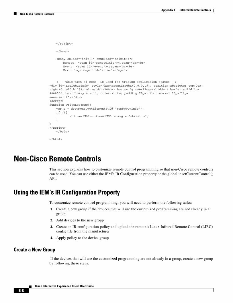
Appendix E Infrared Remote ControlsNon-Cisco Remote Controls
</script>
</head>
<body onload="init()" onunload="deinit()">Remote: <span id="remoteInfo"></span><br><br>Event: <span id="event"></span><br><br>Error log: <span id="error"></span>
<!-- This part of code is used for tracing application states -->
<div id="appDebugInfo" style="background:rgba(0,0,0,.9); position:absolute; top:0px; right:0; width:15%; min-width:300px; bottom:0; overflow-x:hidden; border:solid 1px #666666; overflow-y:scroll; color:white; padding:20px; font:normal 10px/12px sans-serif"></div><script>function writeLog(msg){
var c = document.getElementById('appDebugInfo');if(c){
c.innerHTML=c.innerHTML + msg + "<br><br>";}
}</script>
</body>
</html>
Non-Cisco Remote ControlsThis section explains how to customize remote control programming so that non-Cisco remote controls can be used. You can use either the IEM’s IR Configuration property or the global.ir.setCurrentControl() API.
Using the IEM’s IR Configuration PropertyTo customize remote control programming, you will need to perform the following tasks:
1. Create a new group if the devices that will use the customized programming are not already in a group
2. Add devices to the new group
3. Create an IR configuration policy and upload the remote’s Linux Infrared Remote Control (LIRC) config file from the manufacturer
4. Apply policy to the device group
Create a New Group
If the devices that will use the customized programming are not already in a group, create a new group by following these steps:
E-8Cisco Interactive Experience Client User Guide
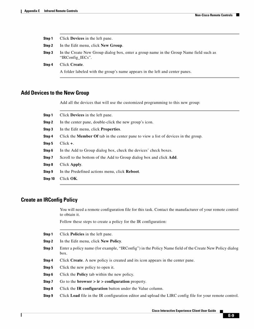
Appendix E Infrared Remote ControlsNon-Cisco Remote Controls
Step 1 Click Devices in the left pane.
Step 2 In the Edit menu, click New Group.
Step 3 In the Create New Group dialog box, enter a group name in the Group Name field such as “IRConfig_IECs”.
Step 4 Click Create.
A folder labeled with the group’s name appears in the left and center panes.
Add Devices to the New Group
Add all the devices that will use the customized programming to this new group:
Step 1 Click Devices in the left pane.
Step 2 In the center pane, double-click the new group’s icon.
Step 3 In the Edit menu, click Properties.
Step 4 Click the Member Of tab in the center pane to view a list of devices in the group.
Step 5 Click +.
Step 6 In the Add to Group dialog box, check the devices’ check boxes.
Step 7 Scroll to the bottom of the Add to Group dialog box and click Add.
Step 8 Click Apply.
Step 9 In the Predefined actions menu, click Reboot.
Step 10 Click OK.
Create an IRConfig Policy
You will need a remote configuration file for this task. Contact the manufacturer of your remote control to obtain it.
Follow these steps to create a policy for the IR configuration:
Step 1 Click Policies in the left pane.
Step 2 In the Edit menu, click New Policy.
Step 3 Enter a policy name (for example, “IRConfig”) in the Policy Name field of the Create New Policy dialog box.
Step 4 Click Create. A new policy is created and its icon appears in the center pane.
Step 5 Click the new policy to open it.
Step 6 Click the Policy tab within the new policy.
Step 7 Go to the browser > ir > configuration property.
Step 8 Click the IR configuration button under the Value column.
Step 9 Click Load file in the IR configuration editor and upload the LIRC config file for your remote control.
E-9Cisco Interactive Experience Client User Guide
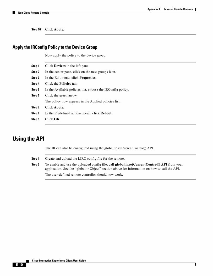
Appendix E Infrared Remote ControlsNon-Cisco Remote Controls
Step 10 Click Apply.
Apply the IRConfig Policy to the Device Group
Now apply the policy to the device group:
Step 1 Click Devices in the left pane.
Step 2 In the center pane, click on the new groups icon.
Step 3 In the Edit menu, click Properties.
Step 4 Click the Policies tab.
Step 5 In the Available policies list, choose the IRConfig policy.
Step 6 Click the green arrow.
The policy now appears in the Applied policies list.
Step 7 Click Apply.
Step 8 In the Predefined actions menu, click Reboot.
Step 9 Click OK.
Using the APIThe IR can also be configured using the global.ir.setCurrentControl() API.
Step 1 Create and upload the LIRC config file for the remote.
Step 2 To enable and use the uploaded config file, call global.ir.setCurrentControl() API from your application. See the “global.ir Object” section above for information on how to call the API.
The user-defined remote controller should now work.
E-10Cisco Interactive Experience Client User Guide
A P P E N D I X F
Video Conferencing Using the Session Initiation Protocol ClientRevised: February 16, 2016
Appendix OverviewThe Session Initiation Protocol (SIP) client enables a customer at the kiosk to make a SIP audio and video call with a remote assistant.
Topics in this appendix include:
• “SIP Recommendations”
• “SipPhone Widget”
– “Sample Test Code”
• “IEC Preparation”
• “SIP Client”
• “Cisco IP Phone Set Up on the CUCM”
– “Finding The IP Phone’s MAC Address”
• “Cisco IEC Set Up on the CUCM”
• “Configuring Call Manager Information”
– “Using a Policy on the IEM”
– “Using the SipPhone Widget”
• “SIP DTMF”
– “Sample usage of sendDtmf() API”
SIP RecommendationsThe following are recommendations when using SIP:
• SIP video quality is dependent on the available network link. At least 1Mbps of available bandwidth between the end-points is recommended for HD-quality video call.
F-1Cisco Interactive Experience Client User Guide
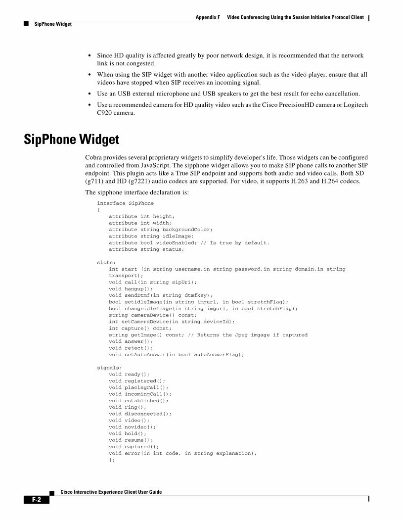
Appendix F Video Conferencing Using the Session Initiation Protocol ClientSipPhone Widget
• Since HD quality is affected greatly by poor network design, it is recommended that the network link is not congested.
• When using the SIP widget with another video application such as the video player, ensure that all videos have stopped when SIP receives an incoming signal.
• Use an USB external microphone and USB speakers to get the best result for echo cancellation.
• Use a recommended camera for HD quality video such as the Cisco PrecisionHD camera or Logitech C920 camera.
SipPhone WidgetCobra provides several proprietary widgets to simplify developer's life. Those widgets can be configured and controlled from JavaScript. The sipphone widget allows you to make SIP phone calls to another SIP endpoint. This plugin acts like a True SIP endpoint and supports both audio and video calls. Both SD (g711) and HD (g7221) audio codecs are supported. For video, it supports H.263 and H.264 codecs.
The sipphone interface declaration is:
interface SipPhone{
attribute int height;attribute int width;attribute string backgroundColor;attribute string idleImage;attribute bool videoEnabled; // Is true by default.attribute string status;
slots:int start (in string username,in string password,in string domain,in string transport);void call(in string sipUri);void hangup();void sendDtmf(in string dtmfkey);bool setidleImage(in string imgurl, in bool stretchFlag);bool changeidleImage(in string imgurl, in bool stretchFlag);string cameraDevice() const;int setCameraDevice(in string deviceId);int capture() const;string getImage() const; // Returns the Jpeg imgage if capturedvoid answer();void reject();void setAutoAnswer(in bool autoAnswerFlag);
signals:void ready();void registered();void placingCall();void incomingCall();void established();void ring();void disconnected();void video();void novideo();void hold();void resume();void captured();void error(in int code, in string explanation);};
F-2Cisco Interactive Experience Client User Guide
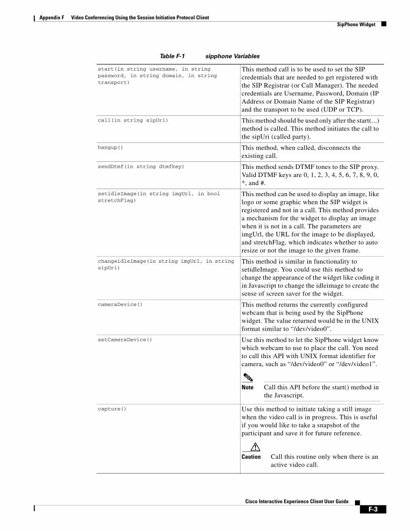
Appendix F Video Conferencing Using the Session Initiation Protocol ClientSipPhone Widget
Table F-1 sipphone Variables
start(in string username, in string password, in string domain, in string transport)
This method call is to be used to set the SIP credentials that are needed to get registered with the SIP Registrar (or Call Manager). The needed credentials are Username, Password, Domain (IP Address or Domain Name of the SIP Registrar) and the transport to be used (UDP or TCP).
call(in string sipUri) This method should be used only after the start(...) method is called. This method initiates the call to the sipUri (called party).
hangup() This method, when called, disconnects the existing call.
sendDtmf(in string dtmfkey) This method sends DTMF tones to the SIP proxy. Valid DTMF keys are 0, 1, 2, 3, 4, 5, 6, 7, 8, 9, 0, *, and #.
setidleImage(in string imgUrl, in bool stretchFlag)
This method can be used to display an image, like logo or some graphic when the SIP widget is registered and not in a call. This method provides a mechanism for the widget to display an image when it is not in a call. The parameters are imgUrl, the URL for the image to be displayed, and stretchFlag, which indicates whether to auto resize or not the image to the given frame.
changeidleImage(in string imgUrl, in string sipUri)
This method is similar in functionality to setidleImage. You could use this method to change the appearance of the widget like coding it in Javascript to change the idleimage to create the sense of screen saver for the widget.
cameraDevice() This method returns the currently configured webcam that is being used by the SipPhone widget. The value returned would be in the UNIX format similar to “/dev/video0”.
setCameraDevice() Use this method to let the SipPhone widget know which webcam to use to place the call. You need to call this API with UNIX format identifier for camera, such as “/dev/video0” or “/dev/video1”.
Note Call this API before the start() method in the Javascript.
capture() Use this method to initiate taking a still image when the video call is in progress. This is useful if you would like to take a snapshot of the participant and save it for future reference.
Caution Call this routine only when there is an active video call.
F-3Cisco Interactive Experience Client User Guide

Appendix F Video Conferencing Using the Session Initiation Protocol ClientSipPhone Widget
getImage() Call this method after you have received a captured() signal. When called, this routine returns base64 content of the JPEG image captured.
answer() Accepts incoming call.
reject() Rejects incoming call.
setAutoAnswer(in bool autoAnswerFlag) Enables auto answer mode if the autoAnswerFlag is “true”.
ready() This signal is indicative that values given for initializing the SIP phone are accepted.
registered() This signal means that the SIP phone is now registered with the SIP Registrar (or Call Manager) and you can make and receive calls from the widget.
placingCall() This signal means the widget is trying to place the call to the called party of interest.
incomingCall() This signal means the widget is receiving an incoming call request from another SIP peer.
established() This signal is indicative that the call is in progress.
ring() This signal means that the called party has been notified about the incoming call.
disconnected() This signal means that the call has been terminated.
video() This signal means that the call was negotiated as a video call and the remote site video is available to display.
novideo() This signal means that the call that was negotiated does not have video being sent by the remote end. The application can use the novideo signal to improve the user experience such as displaying a “Please wait” message.
hold() This signal means that the remote party has put the call on hold. An image can be displayed on the screen when a SIP call is placed on hold. The image that is included in this signal will be shown on the screen.
resume() This signal means that the remote party has resumed the call. Upon receiving this signal, the application will revert to the original screen and the on-hold image will be hidden.
F-4Cisco Interactive Experience Client User Guide

Appendix F Video Conferencing Using the Session Initiation Protocol ClientSipPhone Widget
Sample Test Code<!-- IEC-4.155.393 --><!DOCTYPE html PUBLIC "-//W3C//DTD XHTML 1.0 Transitional//EN" "http://www.w3.org/TR/xhtml1/DTD/xhtml1-transitional.dtd"><html xmlns="http://www.w3.org/1999/xhtml">
<head><meta http-equiv="Content-Type" content="text/html; charset=UTF-8" />
<title>SIP phone</title><style type="text/css">html, body {padding:0; margin:0; width:100%; height:100%}body {background: #1e2024; color: #ffffff; font:normal 12px Arial, Helvetica, sans-serif;}body {background: -webkit-gradient(linear, left top, left bottom, color-stop(0%,rgba(180,180,177,1)), color-stop(32%,rgba(214,213,212,1)), color-stop(100%,rgba(255,255,255,1))); background: -webkit-linear-gradient(top, rgba(180,180,177,1) 0%,rgba(214,213,212,1) 32%,rgba(255,255,255,1) 100%);}ul, ol, li {padding:0; margin:0;}.vbox, .hbox {display: -webkit-box;display: box;-webkit-box-pack: justify;box-pack: justify;text-align:justify;text-align:center;}.vbox {-webkit-box-orient: vertical;box-orient: vertical;}.hbox {-webkit-box-orient: horizontal;box-orient: horizontal;}.fullwindow {height:100%; width:100%;display: -webkit-box;display: box;
captured() This signal is fired when an user action of taking a still snapshot of an video call is successfully finished. Once this signal is fired, the application can call getImage() to get the captured image (as a JPEG image).
error(in int code, in string explaination) This signal is indicative of any errors whilst the widget operation. The signal has a code and an explanation about the error that was encountered.
Error Codes:
404: No answer
401: Registration failed
485: User busy
494: User not found
486: Call manager not able to route call
503: Service unavailable
F-5Cisco Interactive Experience Client User Guide

Appendix F Video Conferencing Using the Session Initiation Protocol ClientSipPhone Widget
-webkit-box-orient: horizontal;box-orient: horizontal;-webkit-box-pack: justify;box-pack: justify;}/*============ SIP ================*/.LED_red, .LED_green, .LED_white, .LED_off {width:44px; height:24px; background:transparent url('img/LED_off.png') center center no-repeat;}.LED_red {background-image:url('img/LED_red.png');}.LED_green {background-image:url('img/LED_green.png');}.LED_white {background-image:url('img/LED_white.png');}.topPanel {background:#0e1014 url('img/top_panel_bg.png') top left repeat-x; color:#4c5058; text-shadow:0 -1px 1px #000; font:normal 14px Arial, Helvetica, sans-serif; height:41px;}.status {color:#848d9d; text-shadow:0 -1px 1px #000; font:normal 14px Arial, Helvetica, sans-serif; padding:0 20px}.bottomPanel {background:#0e1014 url('img/bottom_panel_bg.png') top left repeat-x; color:#4c5058; text-shadow:0 -1px 1px #000; font:normal 14px Arial, Helvetica, sans-serif; height:80px;}.calltime {color:#b1b6c3; font:normal 14px Arial, Helvetica, sans-serif; height:41px; text-shadow:0 -1px 1px #000;}.buttons {text-align:center; display:inline-block; padding:0 30px 0 30px;}.greenButton, .redButton, .callButton, .endCallButton, .hangupButton, .acceptButton, .rejectButton {width:170px; height:56px; background:transparent; -webkit-border-image: url('img/greenButton_disabled.png') 1 10 1 10 stretch stretch; border-width:1px 10px 1px 10px; color:rgba(255,255,255,.9); font:normal 22px Arial, Helvetica, sans-serif; padding-top:6px; text-shadow:0 -1px 1px rgba(0,0,0,.6)}.greenButton, .callButton, .acceptButton {-webkit-border-image: url('img/greenButton_idle.png') 1 10 1 10 stretch stretch;}.greenButton:hover, .callButton:hover, .acceptButton:hover {-webkit-border-image: url('img/greenButton_hover.png') 1 10 1 10 stretch stretch;}.greenButton:active, .callButton:active, .acceptButton:active {-webkit-border-image: url('img/greenButton_pressed.png') 1 10 1 10 stretch stretch;}.greenButton:disabled, .callButton:disabled, .acceptButton:disabled {-webkit-border-image: url('img/greenButton_disabled.png') 1 10 1 10 stretch stretch; color:#51565d}.redButton, .endCallButton, .hangupButton, .rejectButton {-webkit-border-image: url('img/redButton_idle.png') 1 10 1 10 stretch stretch;}.redButton:hover, .endCallButton:hover, .hangupButton:hover, .rejectButton:hover {-webkit-border-image: url('img/redButton_hover.png') 1 10 1 10 stretch stretch;}.redButton:active, .endCallButton:active, .hangupButton:active, .rejectButton:active {-webkit-border-image: url('img/redButton_pressed.png') 1 10 1 10 stretch stretch;}.redButton:disabled, .endCallButton:disabled, .hangupButton:disabled, .rejectButton:disabled {-webkit-border-image: url('img/redButton_disabled.png') 1 10 1 10 stretch stretch; color:#51565d}.view {background:#000; border:solid 1px #3b3d40; text-align:center; width:640px;height:380px;}.timerOn, .timerOff {color:#b1b6c3; font:normal 36px Arial, Helvetica, sans-serif; height:41px; text-shadow:0 -1px 1px #000;}.timerOff {color:#292e33}.dislpad_disabled {width:43px; height:43px; background:transparent url('img/dialpad_disabled.png') center center no-repeat; border:none}</style><script>var sipphone, sipButton, sipRejectButton, sipTimer, sipStatus, sipRegistered;var callInProgress;var sip_target = "133";var sip_username = "vep1";var sip_password = "user132resu";var sip_domain = "192.168.0.108";var sip_transport = "udp";
F-6Cisco Interactive Experience Client User Guide

Appendix F Video Conferencing Using the Session Initiation Protocol ClientSipPhone Widget
var useApplicationData = true;function initSIP(){writeLog('Starting SIP widget:');callInProgress = false;sipphone = document.getElementById("sipphone");sipbutton = document.getElementById("CallButton");//sipRejectButton = document.getElementById("RejectButton");sipTimer = document.getElementById("callTimer");sipRegistered = document.getElementById("registeredLED");sipStatus = document.getElementById("SIPstatus");var dafault_target = sip_target;var dafault_username = sip_username;var dafault_password = sip_password;var dafault_domain = sip_domain;var dafault_transport = sip_transport;if(useApplicationData){writeLog('Using application data.');// These are the Credentials for the SIP endpoint// It is recommended that you use the// Application Data at the IEM profile to set these// Values and get them via the global.applicationData.value() API.sip_target = global.applicationData.value("sip.target", dafault_target);sip_username = global.applicationData.value("sip.username", dafault_username);sip_password = global.applicationData.value("sip.password", dafault_password);sip_domain = global.applicationData.value("sip.domain", dafault_domain);sip_transport = global.applicationData.value("sip.transport", dafault_transport)}writeLog("username = "+sip_username+"<br>"+"password = "+sip_password+"<br>"+"domain = "+sip_domain+"<br>"+"transport = "+sip_transport+"<br>"+"target = "+sip_target+"<br>");sipbutton.disabled = true;sipRegistered.className = "LED_off";countDown(0);sipStatus.innerHTML = "Connecting to server...";writeLog("Starting SIP daemon...");sipphone.start(sip_username, sip_password, sip_domain, sip_transport);writeLog("Connecting signals...");sipphone.ready.connect(onReady); writeLog("onReady() connected to sipphone.ready");sipphone.registered.connect(onRegistered); writeLog("onRegistered() connected to sipphone.registered");sipphone.placingCall.connect(onPlacingCall); writeLog("onPlacingCall() connected to sipphone.placingCall");sipphone.established.connect(onEstablished); writeLog("onEstablished() connected to sipphone.established");sipphone.disconnected.connect(onDisconnected); writeLog("onDisconnected() connected to sipphone.disconnected");sipphone.ring.connect(onRing); writeLog("onRing() connected to sipphone.ring");sipphone.incomingCall.connect(onIncomingCall); writeLog("onIncomingCall() connected to sipphone.incomingCall");sipphone.error.connect(onError); writeLog("onError() connected to sipphone.error");writeLog("SIP widget started, all signals are connected.");}function onReady(){writeLog("sipphone.status = "+sipphone.status);sipbutton.disabled = true;sipbutton.className="callButton";sipbutton.innerHTML="Call";sipStatus.innerHTML = "Ready";sipTimer.className = "timerOff";//sipRegistered.className = "LED_white";writeLog('onReady() READY');}
F-7Cisco Interactive Experience Client User Guide

Appendix F Video Conferencing Using the Session Initiation Protocol ClientSipPhone Widget
var checkRegistrationStatusTimeout;function onRegistered(){clearTimeout(checkRegistrationStatusTimeout);writeLog("sipphone.status = "+sipphone.status);var success = (sipphone.status=="register successful"); // CHECK REGISTRATION STATUSif(success){sipbutton.disabled = false;sipbutton.className="callButton";sipbutton.innerHTML="Call";sipStatus.innerHTML = "Ready";sipTimer.className = "timerOff";sipRegistered.className = "LED_green";writeLog('onRegistered() REGISTERED');} else {sipbutton.disabled = true;sipbutton.className="callButton";sipbutton.innerHTML=" ";sipStatus.innerHTML = "Connecting to server...";sipTimer.className = "timerOff";sipRegistered.className = "LED_off";writeLog('Waiting for server...');checkRegistrationStatusTimeout = setTimeout("onRegistered()", 15000);}}function onPlacingCall(){writeLog("sipphone.status = "+sipphone.status);sipbutton.className="hangupButton";sipbutton.innerHTML="Cancel";sipStatus.innerHTML = "Placing call...";sipTimer.className = "timerOn";writeLog('onPlacingCall()');}function onIncomingCall(){writeLog("sipphone.status = "+sipphone.status);sipbutton.disabled = false;sipbutton.className="acceptButton";sipbutton.innerHTML="Accept Call";sipStatus.innerHTML = "Incoming call";sipTimer.className = "timerOn";writeLog('onIncomingCall()');}function onEstablished(){writeLog("sipphone.status = "+sipphone.status);callInProgress = true;sipbutton.disabled = false;sipbutton.className="hangupButton";sipbutton.innerHTML="End Call";sipStatus.innerHTML = "In Call";sipTimer.className = "timerOn";countDown(1);writeLog("onEstablished()");writeLog("callInProgress = "+callInProgress);}function onRing(){writeLog("sipphone.status = "+sipphone.status);sipbutton.disabled = false;sipbutton.className="hangupButton";sipbutton.innerHTML="Cancel";sipStatus.innerHTML = "Calling...";sipTimer.className = "timerOn";writeLog('onRing()');}function onDisconnected(){
F-8Cisco Interactive Experience Client User Guide

Appendix F Video Conferencing Using the Session Initiation Protocol ClientSipPhone Widget
writeLog("sipphone.status = "+sipphone.status);callInProgress = false;sipbutton.disabled = false;sipbutton.className="callButton";sipbutton.innerHTML="Call";sipStatus.innerHTML = "Ready";sipTimer.className = "timerOff";countDown(0);writeLog('onDisconnected()');}var t1;function onError(code, explanation){writeLog("sipphone.status = "+sipphone.status);callInProgress = false;sipbutton.disabled = true;sipbutton.className="callButton";sipbutton.innerHTML="Call";sipTimer.className = "timerOff";countDown(0);switch(code){case 404:sipStatus.innerHTML = "<span style='color:#ff0000;'>No answer</span>";break;case 401:sipStatus.innerHTML = "<span style='color:#ff0000;'>Registration failed</span>";break;default:sipStatus.innerHTML = "<span style='color:#ff6920;'>Error</span>";break;}t1 = setTimeout(function(){sipbutton.disabled = false;sipStatus.innerHTML = "Ready";}, 30000);writeLog("onError() " + explanation + " (SIP code = " + code +")");}function makeCall(targetID){writeLog("sipphone.status = "+sipphone.status);sipbutton.disabled = true;var uri = targetID ? targetID : sip_target;uri = uri.indexOf("sip:")<0 ? "sip:" + uri : uri;if(callInProgress){callInProgress = false;sipphone.hangup();writeLog("hangup(); callInProgress = "+callInProgress);} else {callInProgress = true;sipphone.call(uri);writeLog("calling " + uri+" / callInProgress = "+callInProgress);}}// For Timing to be shownvar sip_sec = 00; // set the secondsvar sip_min = 00; // set the minutesvar sip_hrs = 00; // set the Hoursvar sip_OneSecond;function countDown(flag){var calltime;if (flag) {sip_sec++;if (sip_sec == 59) {sip_sec = 00;sip_min = sip_min + 1;}
F-9Cisco Interactive Experience Client User Guide

Appendix F Video Conferencing Using the Session Initiation Protocol ClientSipPhone Widget
if (sip_min == 59) {sip_min = 00;sip_hrs = sip_hrs + 1;}if (sip_sec <= 9){sip_sec = "0" + sip_sec;}calltime = (sip_hrs<1 ? "" : ((sip_hrs<=9 ? "0" + sip_hrs : sip_hrs) + ":")) + (sip_min<=9 && sip_hrs>0 ? "0" + sip_min : sip_min) + ":" + sip_sec;sipTimer.innerHTML = calltime;sipTimer.title = "Last call duration: "+calltime;sip_OneSecond = setTimeout("countDown(1)", 1000);} else {sipTimer.innerHTML = "0:00";clearTimeout(sip_OneSecond);sip_sec = 00;sip_min = 00;}}function isDebugMode(){var l=String(window.location);var qs=l.substring(l.indexOf("?", 0)+1, l.length);if(qs.indexOf("debug", 0)>=0){document.getElementById('appDebugInfo').style.visibility = "visible";} else {document.getElementById('appDebugInfo').style.visibility = "hidden";}}function init(){isDebugMode();initSIP();}</script></head><body onLoad="init()"><div class="fullwindow hbox"><div class="vbox" style="-webkit-box-flex: 1; box-flex: 1; -webkit-box-pack: center; box-pack: center;" ><table border="0" cellpadding="0" cellspacing="0" width="100%" height="100%"><tr><td align="center"><table border="0" cellpadding="0" cellspacing="1" align="center" bgcolor="#000000"><tr><td class="topPanel"><table border="0" cellpadding="0" cellspacing="0" width="100%" height="100%" style="width:100%; max-width:640px"><tr><td width="49%" style="min-width:160px" align="left"><span class="status" id="SIPstatus"> </span></td><td align="center"><div style="min-width:162px"><table border="0" cellpadding="0" cellspacing="0" height="100%"><tr><td width="44"><div style="width:44px"> </div></td><td width="74" align="center" style="width:74px"><img id="camera" src="img/eye.png" width="30" height="30" /></td><td width="44"><img id="registeredLED" class="LED_off" src="img/spacer.png" width="44" height="24" /></td></tr></table></div></td><td width="49%" style="min-width:160px" align="right"> </td>
F-10Cisco Interactive Experience Client User Guide

Appendix F Video Conferencing Using the Session Initiation Protocol ClientSipPhone Widget
</tr></table></td></tr><tr><td class="view"><object id="sipphone" type="application/x-qt-plugin" classid="sipphone" width="640" height="380" backgroundColor="#333333"></object></td></tr><tr><td class="bottomPanel"><table border="0" cellpadding="0" cellspacing="0" width="100%" height="100%" style="width:100%; max-width:640px"><tr><td align="right" width="49%" style="min-width:160px"><span class="timerOff" id="callTimer" title=""> </span></td><td align="center"><div class="buttons"><button id="CallButton" class="callButton" onclick="makeCall();" disabled="disabled">Call</button></div></td><td width="49%" style="min-width:160px; text-align:right"><div style="display:inline-block; padding:0 20px; width:80%; text-align:left"><input type="button" value="" id="dialpad" class="dislpad_disabled" /></div></td></tr></table></td></tr></table></td></tr></table></div></div><div style="display:none; visibility:hidden"><!-- chaching images --><img src="img/call_idle.png" width="0" height="0" /><img src="img/call_hover.png" width="0" height="0" /><img src="img/call_pressed.png" width="0" height="0" /><img src="img/call_disabled.png" width="0" height="0" /><img src="img/endCall_idle.png" width="0" height="0" /><img src="img/endCall_hover.png" width="0" height="0" /><img src="img/endCall_pressed.png" width="0" height="0" /><img src="img/endCall_disabled.png" width="0" height="0" /><img src="img/accept_idle.png" width="0" height="0" /><img src="img/accept_hover.png" width="0" height="0" /><img src="img/accept_pressed.png" width="0" height="0" /><img src="img/accept_disabled.png" width="0" height="0" /><img src="img/reject_idle.png" width="0" height="0" /><img src="img/reject_hover.png" width="0" height="0" /><img src="img/reject_pressed.png" width="0" height="0" /><img src="img/reject_disabled.png" width="0" height="0" /></div><!-- This part of code is used for tracing application states --><div id="appDebugInfo" style="visibility:hidden; background:rgba(0,0,0,.75); position:absolute; top:0; left:0; width:300px; overflow-x:hidden; overflow-y:scroll; color:white; padding:20px; font:normal 10px/12px sans-serif"></div><script>function writeLog(msg){var c = document.getElementById('appDebugInfo');if(c){c.innerHTML=c.innerHTML + msg + "<br><br>";}}
F-11Cisco Interactive Experience Client User Guide
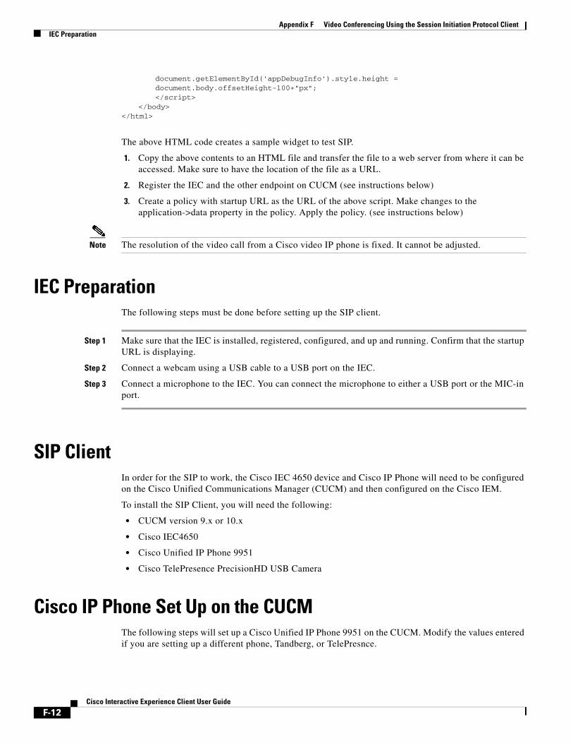
Appendix F Video Conferencing Using the Session Initiation Protocol ClientIEC Preparation
document.getElementById('appDebugInfo').style.height = document.body.offsetHeight-100+"px";</script>
</body></html>
The above HTML code creates a sample widget to test SIP.
1. Copy the above contents to an HTML file and transfer the file to a web server from where it can be accessed. Make sure to have the location of the file as a URL.
2. Register the IEC and the other endpoint on CUCM (see instructions below)
3. Create a policy with startup URL as the URL of the above script. Make changes to the application->data property in the policy. Apply the policy. (see instructions below)
Note The resolution of the video call from a Cisco video IP phone is fixed. It cannot be adjusted.
IEC PreparationThe following steps must be done before setting up the SIP client.
Step 1 Make sure that the IEC is installed, registered, configured, and up and running. Confirm that the startup URL is displaying.
Step 2 Connect a webcam using a USB cable to a USB port on the IEC.
Step 3 Connect a microphone to the IEC. You can connect the microphone to either a USB port or the MIC-in port.
SIP ClientIn order for the SIP to work, the Cisco IEC 4650 device and Cisco IP Phone will need to be configured on the Cisco Unified Communications Manager (CUCM) and then configured on the Cisco IEM.
To install the SIP Client, you will need the following:
• CUCM version 9.x or 10.x
• Cisco IEC4650
• Cisco Unified IP Phone 9951
• Cisco TelePresence PrecisionHD USB Camera
Cisco IP Phone Set Up on the CUCMThe following steps will set up a Cisco Unified IP Phone 9951 on the CUCM. Modify the values entered if you are setting up a different phone, Tandberg, or TelePresnce.
F-12Cisco Interactive Experience Client User Guide

Appendix F Video Conferencing Using the Session Initiation Protocol ClientCisco IP Phone Set Up on the CUCM
Step 1 Enter the IP address of your CUCM in your browser.
Step 2 Press the Enter button.
Step 3 In the CUCM main page, select Cisco Unified Communications Manager.
You will be prompted to the Website’s Security Certificate page.
Step 4 On the Website’s Security Certificate page, click Continue to this website (Not Recommended).
Step 5 Enter admin in the Username field of the Cisco Unified CM Administration page.
Step 6 Enter the password in the Password field.
Step 7 Click Login button.
Step 8 From the Device drop-down menu, choose Phone.
Step 9 Click the Find button.
All the devices registered on the CUCM will be listed.
Step 10 To add a new phone, click Add New.
Step 11 From the Phone Type drop-down menu, choose Cisco 9951.
Step 12 Click Next.
Step 13 Enter the IP phone’s MAC address in the MAC Address field within the Device Information area.
Note If you do not know the IP phone’s MAC address, refer to the section “Finding the IP Phone’s MAC Address” at the end of this section.
Step 14 Enter a description of the IP phone to easily distinguish it from others in the CUCM. This field automatically enters the IP phone’s MAC Address but can be modified.
Step 15 From the Device Pool drop-down menu, choose Default.
Step 16 From the Phone Button Template drop-down menu, choose Standard 9951 SIP.
Step 17 From the Device Security Profile drop-down menu within the Protocol Specific Information area, choose Cisco 9951 - Standard SIP Non-Secure Profile.
Step 18 From the SIP Profile drop-down menu, choose Standard SIP Profile.
Step 19 Within the Protocol Specific Information area, go to the Digest User drop-down menu and choose the User ID.
Step 20 From the Cisco Camera drop-down menu within the Product Specific Configuration Layout, choose Enabled.
Step 21 From the Video Capabilities drop-down menu, choose Enabled.
Step 22 From the Web Access drop-down menu, choose Enabled.
Step 23 Click Save.
A dialog box appears.
Step 24 Click Apply Config.
Note It is important that you first save configurations before applying them. Otherwise, the configurations will be lost.
Step 25 Click OK.
F-13Cisco Interactive Experience Client User Guide
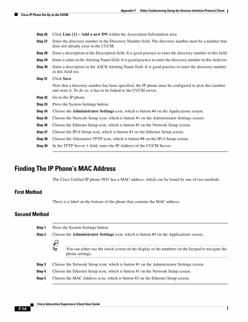
Appendix F Video Conferencing Using the Session Initiation Protocol ClientCisco IP Phone Set Up on the CUCM
Step 26 Click Line [1] – Add a new DN within the Association Information area.
Step 27 Enter the directory number in the Directory Number field. The directory number must be a number that does not already exist in the CUCM.
Step 28 Enter a description in the Description field. It is good practice to enter the directory number in this field.
Step 29 Enter a value in the Alerting Name field. It is good practice to enter the directory number in this field too.
Step 30 Enter a description in the ASCII Alerting Name field. It is good practice to enter the directory number in this field too.
Step 31 Click Save.
Now that a directory number has been specified, the IP phone must be configured to pick this number and store it. To do so, it has to be linked to the CUCM server.
Step 32 Go to the IP phone.
Step 33 Press the System Settings button.
Step 34 Choose the Administrator Settings icon, which is button #4 on the Applications screen.
Step 35 Choose the Network Setup icon, which is button #1 on the Administrator Settings screen.
Step 36 Choose the Ethernet Setup icon, which is button #1 on the Network Setup screen.
Step 37 Choose the IPv4 Setup icon, which is button #1 on the Ethernet Setup screen.
Step 38 Choose the Alternative TFTP icon, which is button #8 on the IPv4 Setup screen.
Step 39 In the TFTP Server 1 field, enter the IP Address of the CUCM Server.
Finding The IP Phone’s MAC AddressThe Cisco Unified IP phone 9951 has a MAC address, which can be found by one of two methods.
First Method
There is a label on the bottom of the phone that contains the MAC address.
Second Method
Step 1 Press the System Settings button.
Step 2 Choose the Administrator Settings icon, which is button #4 on the Applications screen.
Tip You can either use the touch screen on the display or the numbers on the keypad to navigate the phone settings.
Step 3 Choose the Network Setup icon, which is button #1 on the Administrator Settings screen.
Step 4 Choose the Ethernet Setup icon, which is button #1 on the Network Setup screen.
Step 5 Choose the MAC Address icon, which is button #2 on the Ethernet Setup screen.
F-14Cisco Interactive Experience Client User Guide

Appendix F Video Conferencing Using the Session Initiation Protocol ClientCisco IEC Set Up on the CUCM
Cisco IEC Set Up on the CUCMThe Cisco IEC 4650 device set up on the CUCM is very similar to the Cisco IP Phone 9951 set up on the CUCM except for a few options. An additional step is also required. This step is the setting up of a User Profile. The User Profile is then linked to the Cisco IEC 4650 device after it is set up on the CUCM.
Step 1 Enter the IP address of your CUCM in your browser.
Step 2 Press the Enter button.
Step 3 In the CUCM main page, select Cisco Unified Communications Manager.
You will be prompted to the Website’s Security Certificate page.
Step 4 On the Website’s Security Certificate page, click Continue to this website (Not Recommended).
Step 5 Enter admin in the Username field of the Cisco Unified CM Administration page.
Step 6 Enter the password in the Password field.
Step 7 Click Login button.
Step 8 From the Device drop-down menu, choose Phone.
Step 9 Click the Find button.
All the devices registered on the CUCM will be listed.
Step 10 To add a new phone, click Add New.
Step 11 From the Phone Type drop-down menu, choose Third Party SIP Device (Advanced).
Step 12 Click Next.
Step 13 Enter the Cisco IEC 4650 device’s MAC address in the MAC Address field within the Device Information area.
Note The Cisco IEC 4650 device’s MAC address is located on the label on the back of the device.
Step 14 Enter a description of the Cisco IEC 4650 device. This field automatically enters “SEP” plus the MAC Address but the field can be modified.
Step 15 From the Device Pool drop-down menu, choose Default.
Step 16 From the Phone Button Template drop-down menu, choose Third Party SIP Device (Advanced).
Step 17 From the SIP Profile drop-down menu, choose Standard SIP Profile.
Step 18 From the Device Security Profile drop-down menu, choose Third-party SIP Device Advanced - Standard SIP Non-secure profile.
Step 19 Click Save.
Step 20 Click Apply Config.
In order for the IEC 4650 device to be activated, it must be associated with a User Profile.
Step 21 From the User Management drop-down menu, choose End User.
Step 22 Click Add New.
Step 23 Enter a value in the User ID field. A unique numeric value is required to identify the user. This unique value will be the extension of the SIP device.
F-15Cisco Interactive Experience Client User Guide

Appendix F Video Conferencing Using the Session Initiation Protocol ClientCisco IEC Set Up on the CUCM
Note It is imperative that the value entered in the User ID field is a number. The SIP device will not work if you enter alphabetic characters, punctuation, or spaces.
Step 24 Enter a password in the Password field.
Step 25 Re-enter the password in the Confirm Password field.
Step 26 Enter the last name of the user in the Last Name field.
Step 27 Click Save.
You will be redirected to a page where you can find the status of your User Profile creation. If all fields have been entered properly the status will indicate ‘Add Successful’.
The user profile and the Cisco IEC 4650 device on the CUSM must now be linked in order for the phone to work.
Step 28 From the Device drop-down menu, choose Phone.
Step 29 Click the Find button.
All the devices registered on the CUCM will be listed.
Step 30 Choose the Cisco IEC 4650 device, which starts with the letters “SEP” followed by the MAC address.
Step 31 On the Phone Configuration screen, choose Line [1] – Add a new DN within the Association Information area.
The Directory Number Configuration page appears.
Step 32 Enter a number in the Directory Number field.
Step 33 Click Save.
Step 34 Click Associate End Users.
The user list screen appears.
Step 35 Click Find.
Step 36 Check the check box next to the user that you would like to associate the IEC directory number.
Step 37 Click Add Selected.
Step 38 Click Close.
Step 39 From the Device drop-down menu, choose Phone.
Step 40 Click Save.
Step 41 Click Apply Config.
Step 42 Within the Protocol Specific Information area, go to the Digest User drop-down menu and choose the User ID.
Step 43 Click Save.
Step 44 Click Apply Config.
This Cisco IEC 4650 device is now registered on the CUCM.
F-16Cisco Interactive Experience Client User Guide

Appendix F Video Conferencing Using the Session Initiation Protocol ClientConfiguring Call Manager Information
Configuring Call Manager InformationOnce the end points (the video IP phone and an IEC) have been registered on the CUCM, you have several options for configuring the call manager information so that the IEC can call or receive calls from the video IP phone:
• You can enter the call manager information in a policy on the IEM.
• You can hard code the call manager information in the sipphone widget.
Using a Policy on the IEMThe following steps explain how to enter the call manager information into the IEC’s policy on the IEM.
Step 1 Log in to the Cisco IEM which has the SIP policy enabled on it.
Step 2 Go to the policy that is applied to the Cisco IEC4610 or 4632 device.
Step 3 Click the Policy tab.
Step 4 Expand the application property.
Step 5 In the data property, click the value field.
Step 6 In the Application data editor, click +.
Step 7 Click key:value.
Step 8 Enter sip.target in the key field.
Step 9 Enter the directory number in the value field.
Step 10 Click Ok.
If you click on data property’s Value field, you will see the data in the form sip.target:[directoryNumber].
Next you will add the username, password, domain, and transport protocol for the Cisco Unified Communications Manager (CUCM).
Step 11 In the Application data editor, click +.
Step 12 Enter sip.username in the key field.
Step 13 In the value field, enter the username that the IEM will use to log into the CUCM. This is the unique User ID that was entered in the CUCM.
Note It is imperative that the value entered in the User ID field is a number. The SIP device will not work if you enter alphabetic characters, punctuation, or spaces.
Step 14 In the Application data editor, click +.
Step 15 Enter sip.password in the key field.
Step 16 In the value field, enter the password that the IEM will use to log into the CUCM.
Step 17 In the Application data editor, click +.
Step 18 Enter sip.domain in the key field.
Step 19 In the value field, enter the IP address of the CUCM.
Step 20 In the Application data editor, click +.
F-17Cisco Interactive Experience Client User Guide
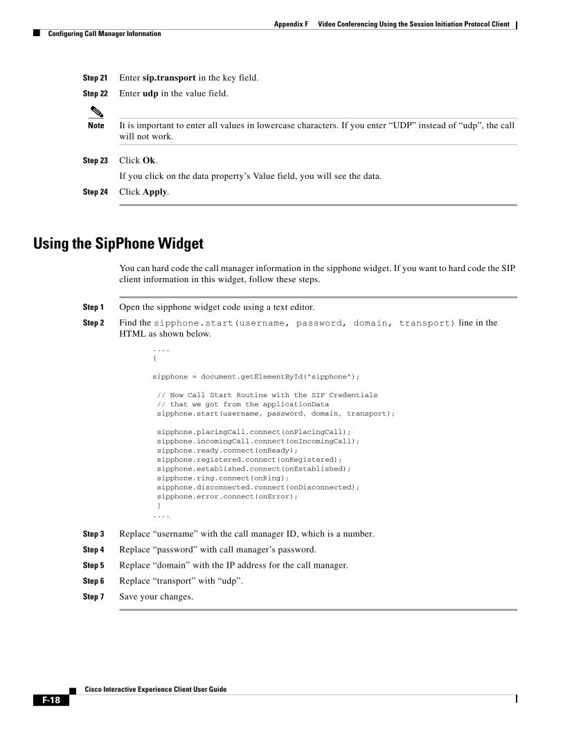
Appendix F Video Conferencing Using the Session Initiation Protocol ClientConfiguring Call Manager Information
Step 21 Enter sip.transport in the key field.
Step 22 Enter udp in the value field.
Note It is important to enter all values in lowercase characters. If you enter “UDP” instead of “udp”, the call will not work.
Step 23 Click Ok.
If you click on the data property’s Value field, you will see the data.
Step 24 Click Apply.
Using the SipPhone WidgetYou can hard code the call manager information in the sipphone widget. If you want to hard code the SIP client information in this widget, follow these steps.
Step 1 Open the sipphone widget code using a text editor.
Step 2 Find the sipphone.start(username, password, domain, transport) line in the HTML as shown below.
....{
sipphone = document.getElementById("sipphone");
// Now Call Start Routine with the SIP Credentials // that we got from the applicationData sipphone.start(username, password, domain, transport);
sipphone.placingCall.connect(onPlacingCall); sipphone.incomingCall.connect(onIncomingCall); sipphone.ready.connect(onReady); sipphone.registered.connect(onRegistered); sipphone.established.connect(onEstablished); sipphone.ring.connect(onRing); sipphone.disconnected.connect(onDisconnected); sipphone.error.connect(onError); }....
Step 3 Replace “username” with the call manager ID, which is a number.
Step 4 Replace “password” with call manager’s password.
Step 5 Replace “domain” with the IP address for the call manager.
Step 6 Replace “transport” with “udp”.
Step 7 Save your changes.
F-18Cisco Interactive Experience Client User Guide
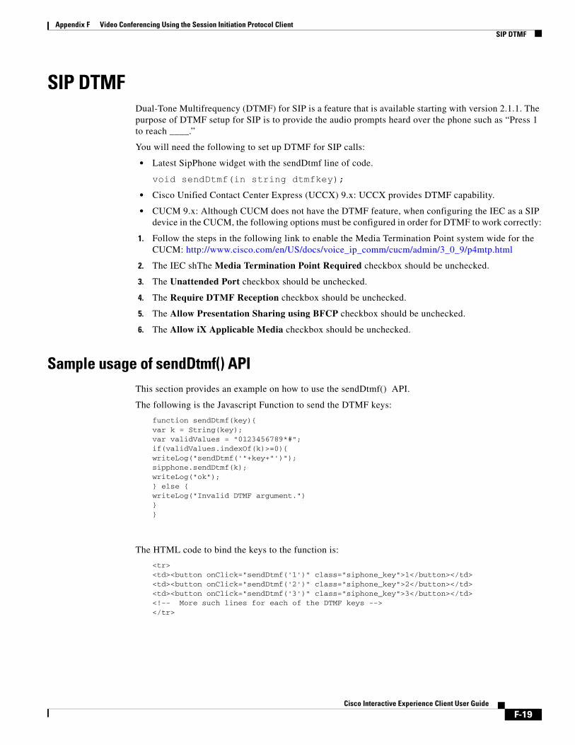
Appendix F Video Conferencing Using the Session Initiation Protocol ClientSIP DTMF
SIP DTMFDual-Tone Multifrequency (DTMF) for SIP is a feature that is available starting with version 2.1.1. The purpose of DTMF setup for SIP is to provide the audio prompts heard over the phone such as “Press 1 to reach ____.”
You will need the following to set up DTMF for SIP calls:
• Latest SipPhone widget with the sendDtmf line of code.
void sendDtmf(in string dtmfkey);• Cisco Unified Contact Center Express (UCCX) 9.x: UCCX provides DTMF capability.
• CUCM 9.x: Although CUCM does not have the DTMF feature, when configuring the IEC as a SIP device in the CUCM, the following options must be configured in order for DTMF to work correctly:
1. Follow the steps in the following link to enable the Media Termination Point system wide for the CUCM: http://www.cisco.com/en/US/docs/voice_ip_comm/cucm/admin/3_0_9/p4mtp.html
2. The IEC shThe Media Termination Point Required checkbox should be unchecked.
3. The Unattended Port checkbox should be unchecked.
4. The Require DTMF Reception checkbox should be unchecked.
5. The Allow Presentation Sharing using BFCP checkbox should be unchecked.
6. The Allow iX Applicable Media checkbox should be unchecked.
Sample usage of sendDtmf() APIThis section provides an example on how to use the sendDtmf() API.
The following is the Javascript Function to send the DTMF keys:
function sendDtmf(key){var k = String(key);var validValues = "0123456789*#";if(validValues.indexOf(k)>=0){writeLog("sendDtmf('"+key+"')");sipphone.sendDtmf(k);writeLog("ok");} else {writeLog("Invalid DTMF argument.")}}
The HTML code to bind the keys to the function is:
<tr><td><button onClick="sendDtmf('1')" class="siphone_key">1</button></td><td><button onClick="sendDtmf('2')" class="siphone_key">2</button></td><td><button onClick="sendDtmf('3')" class="siphone_key">3</button></td><!-- More such lines for each of the DTMF keys --></tr>
F-19Cisco Interactive Experience Client User Guide

Appendix F Video Conferencing Using the Session Initiation Protocol ClientSIP DTMF
F-20Cisco Interactive Experience Client User Guide

A P
Cisco
P E N D I XG
Stream Live VideoRevised: February 16, 2016
Appendix OverviewTo stream live video from the IEC to other endpoints, you will need a video encoder dongle and an input source such as a camera, camcorder, or IEC. This appendix describes a set up using the dongle and a document camera that can be used to stream a document, a training session, a meeting, or a demo.
Topics in this appendix include:
• “System Dimensions Video Encoder Dongle”
• “Vaddio HD Document Camera”
• “Stream Live Video”
– “Connect Hardware”
– “global.videoEncoder Object”
System Dimensions Video Encoder DongleThe System Dimensions AVS 2610 is a video encoder dongle that is HDMI compatible. When connected to the IEC and a camera, live video is captured by a HD video camera and then streamed by the dongle to other IECs or remote computers.
The video stream is sent as part of the MPEG2 Transport Protocol (MPEG-TS). The stream can be sent as either unicast or multicast.
• Unicast: The dongle can be used for a point-to-point video stream, for example, when a customer wants to share their document with a virtual agent at a remote site. The stream is sent from an IEC to a single endpoint such as another IEC or a remote computer.
• Multicast: The dongle can be used to allow multiple endpoints to view the same video stream such as for a meeting or a training session. To accomplish this, the stream is sent to a multicast address, which is a virtual address, and then anyone within the multicast group can access the stream at the multicast address.
Note A media server is not necessary for streaming to a multicast address if your network is multicast-enabled. If you cannot do multicasting on your network, then you need a streaming media server.
G-1 Interactive Experience Client User Guide

Appendix G Stream Live VideoVaddio HD Document Camera
If the destination of the stream is another IEC, the native video player of the IEC will receive the video stream and display it. If the destination is a computer, you will need a player on that computer that is capable of receiving H.264 video codec and MPEG-TS as well as decoding UDP multicast streams; a VLC player will meet these requirements. If a robust streaming solution is needed, a media server that receives both UDP multicast and TCP unicast streams could be placed on the network between the streaming endpoint and the receiving endpoints.
Vaddio HD Document CameraThe Vaddio CeilingVIEW™ HD-18 DocCAM is a high-definition ceiling-mounted document camera connected to the IEC via a video encoder dongle. The Vaddio camera can capture documents that the customer is holding or places on the desk or table below the camera. This camera can also be used to capture live events such as demos or lectures.
The Vaddio document camera has the following features:
• Supports 16:9 resolutions at 1080p, 1080i and 720p and 4:3 resolutions at 480i and 576i
• Component HD (1080p, 1080i or 720p) or RGBHV outputs
• 18X optical zoom lens
• 1.3 megapixel 1/3-type CCD image sensor for precise HD video image acquisition even in low light applications
• 16-position rotary switch to select HD camera resolutions
Table G-1 Vaddio HD Camera Resolutions
Rotary Switch Setting HD Camera Resolution
0 720p/59.94
1 1080i/59.94
2 1080p/59.94
3 1080p/60
4 720p/50
5 1080i/50
6 1080p/50
7 1080p/30
8 1080p/25
9 1024 x 768/60 RGBHV
A
B
C
D
E 1280 x 800/60 RGBHV
F 1680 x 1050/60 RGBHV
G-2Cisco Interactive Experience Client User Guide
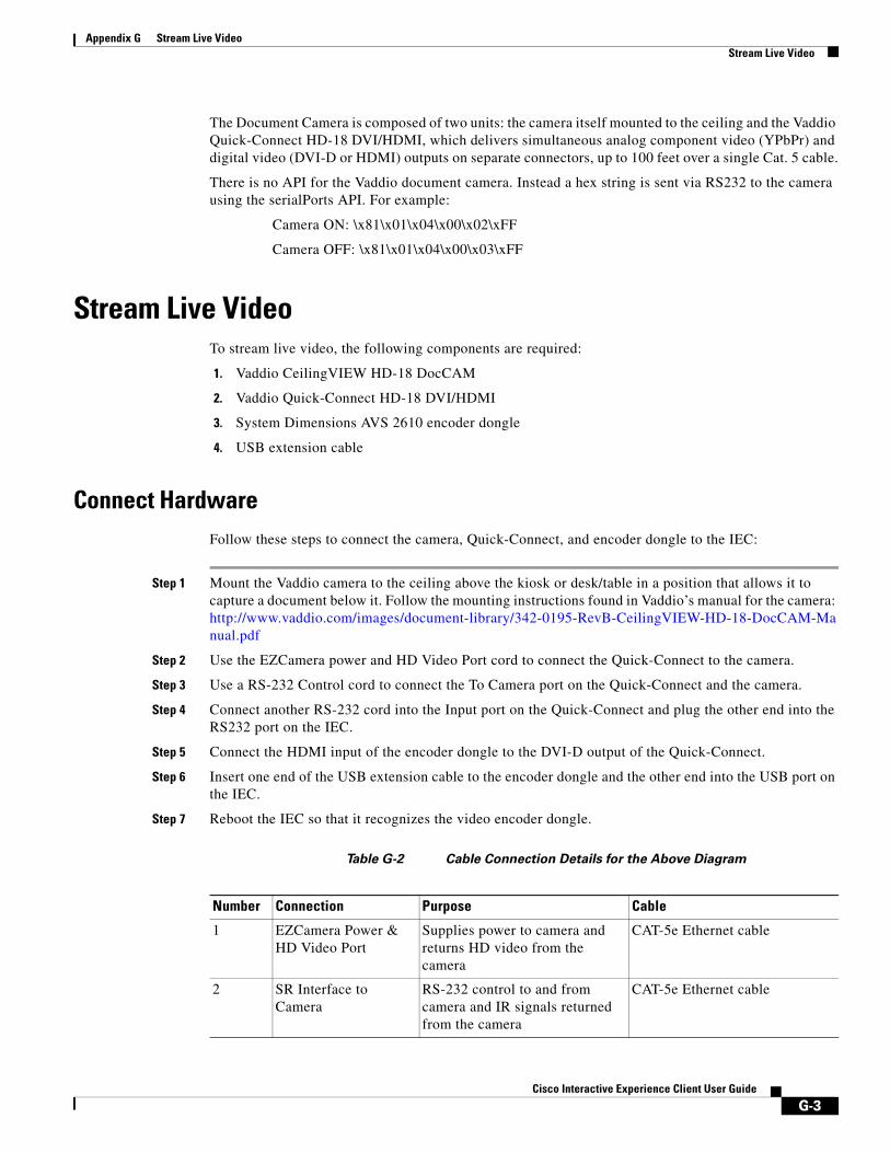
Appendix G Stream Live VideoStream Live Video
The Document Camera is composed of two units: the camera itself mounted to the ceiling and the Vaddio Quick-Connect HD-18 DVI/HDMI, which delivers simultaneous analog component video (YPbPr) and digital video (DVI-D or HDMI) outputs on separate connectors, up to 100 feet over a single Cat. 5 cable.
There is no API for the Vaddio document camera. Instead a hex string is sent via RS232 to the camera using the serialPorts API. For example:
Camera ON: \x81\x01\x04\x00\x02\xFF
Camera OFF: \x81\x01\x04\x00\x03\xFF
Stream Live VideoTo stream live video, the following components are required:
1. Vaddio CeilingVIEW HD-18 DocCAM
2. Vaddio Quick-Connect HD-18 DVI/HDMI
3. System Dimensions AVS 2610 encoder dongle
4. USB extension cable
Connect HardwareFollow these steps to connect the camera, Quick-Connect, and encoder dongle to the IEC:
Step 1 Mount the Vaddio camera to the ceiling above the kiosk or desk/table in a position that allows it to capture a document below it. Follow the mounting instructions found in Vaddio’s manual for the camera: http://www.vaddio.com/images/document-library/342-0195-RevB-CeilingVIEW-HD-18-DocCAM-Manual.pdf
Step 2 Use the EZCamera power and HD Video Port cord to connect the Quick-Connect to the camera.
Step 3 Use a RS-232 Control cord to connect the To Camera port on the Quick-Connect and the camera.
Step 4 Connect another RS-232 cord into the Input port on the Quick-Connect and plug the other end into the RS232 port on the IEC.
Step 5 Connect the HDMI input of the encoder dongle to the DVI-D output of the Quick-Connect.
Step 6 Insert one end of the USB extension cable to the encoder dongle and the other end into the USB port on the IEC.
Step 7 Reboot the IEC so that it recognizes the video encoder dongle.
Table G-2 Cable Connection Details for the Above Diagram
Number Connection Purpose Cable
1 EZCamera Power & HD Video Port
Supplies power to camera and returns HD video from the camera
CAT-5e Ethernet cable
2 SR Interface to Camera
RS-232 control to and from camera and IR signals returned from the camera
CAT-5e Ethernet cable
G-3Cisco Interactive Experience Client User Guide

Appendix G Stream Live VideoStream Live Video
global.videoEncoder ObjectThe global.videoEncoder object allows the web application to take a video feed from a HDMI Source and encode it to MPEG-TS and stream it out to an endpoint either via UDP or via TCP. This object can be coupled with the video player and can serve as a local view of the encoded frame that is being sent out on the wire.
Note While using TCP as the connection type, ensure that the TCP endpoint on the host to which you are interested to stream to is listening on the port of interest.
Tip While using the camera, make sure the input resolution that you select is supported by the camera. It is recommended that you use either a 720p or a 1080i. A lower resolution camera may not give the desired output.
interface videoEncoder{
readonly attribute bool isAvailable; // Checks if Encoder is Available readonly attribute int status; readonly attribute int errorCode; readonly attribute string errorMessage; readonly attribute int videoInputCount; readonly attribute stringlist videoInputDescription;
readonly attribute string snapshot;
attribute string targetHost; // Target Host where MPEG2-TS has to be sent attribute int targetPort; // Target Port on Target Host to Receive it attribute int protocol; // Udp=0, Tcp=1 attribute int videoMode; // SD=0, HD=1, CUSTOM=2
3 RS-232 Control Input (A photo of this connection is shown in the figure below)
Input to SR interface from IEC RS-232 port
Shown in figure below:
a) 9 pin male to 3.5mm stereo jack adapter
b) 9 pin female to Ethernet port adapter (comes with Vaddio camera - no need to purchase)
c) CAT-5e Ethernet cable
4 DVI-D Output From SR interface DVI-D to HDMI port of dongle
DVI to HDMI cable: HDMI (v 1.3 with deep color) and DVI v 1.0 compliant
5 HDMI Output From dongle USB to USB port of IEC
Male to female USB cable
Number Connection Purpose Cable
G-4Cisco Interactive Experience Client User Guide

Appendix G Stream Live VideoStream Live Video
attribute int videoSource; // Must be in [0, videoInputCount] range. 0 is for HDMI, 1-videoInputCount is for webcams
attribute int h264Profile; attribute int inputResolution; attribute bool isProgressive; attribute int streamType;
attribute int inputFrameRate; // 15, 24, 30, 60 attribute int outputFrameRate; // 15, 24, 30, 60 attribute int averageOutputBitRate; attribute int minimumOutputBitRate; attribute int maximumOutputBitRate;
attribute int outputResolution;
attribute int audioBitRate;
signals: notready(); ready(); started(); stopped(); error(in int code, in string message);
slots: start(); stop();
takeSnapShot();
}
global.videoEncoder object Variables
Table G-3 global.videoEncoder Object Variables
Variable Description
isAvailable Use this routine to check if the box has videoEncoder Module in it. A ‘true’ value indicates presence of the module.
status Represents status of video encoder. The status are listed in the section below as enumeration for your reference.
errorCode This attribute will be set when an error occurs. Use this attribute for error handling in your application.
errorMessage This routine returns the error string corresponding to the errorCode that was set. Use this function to display an error message to the user in your application.
G-5Cisco Interactive Experience Client User Guide

Appendix G Stream Live VideoStream Live Video
videoInputCount Returns the available video sources including the HDMI input from the USB dongle and all available webcams.
videoInputDescription Returns the description of all video input devices present in the box.
targetHost Returns the target host to which the encoded stream is being sent.
targetPort Returns the port number on which the encoded stream is being sent.
protocol Returns integer value for the Transport Protocol: ‘0’ for UDP or ‘1’ for TCP.
videoMode Returns video mode on which the video encoder is operating. Values are: ‘0’ - SD, ‘1’ - HD, and ‘2’ for Custom.
videoSource Returns the video source being selected for encoding either as ‘0’ for HDMI or ‘1’ for videoInputCount for webcam.
h264Profile Returns the encoding H.264 profile being used by the encoder: ‘0’ for Baseline, ‘1’ for Main, and ‘2’ for Extended Profile.
inputResolution Returns the input resolution that is being used for the source. Possible values are ‘0’ for 1920x1080 resolution, ‘1’ for 1280x720, and ‘2’ for 1024x600.
isProgressive Returns ‘true’ if the scan format is set to Progressive.
streamType Returns the input stream type that is configured on the encoder. Possible values are ‘0’ = Program Stream, ‘1’ = Transport Stream, ‘2’ = MPEG4 Stream (default), ‘3’ = Elementary Stream, and ‘4’ = Raw Stream.
inputFrameRate Returns the Video-In Frame Rate as integer value in fps. Possible values are ‘0’ for 15fps, ‘1’ for 24fps, ‘2’ for 30fps, and ‘3’ for 60 fps.
outputFrameRate Returns the Video-Out Frame Rate as integer value in fps. Possible values are ‘0’ for 15fps, ‘1’ for 24fps, ‘2’ for 30fps, and ‘3’ for 60 fps.
averageOutputBitRate Returns the Video-Out Average Bit Rate in kbps
minimumOutputBitRate Returns the Video-Out Minimum Bit Rate in kbps
maximumOutputBitRate Returns the Video-Out Maximum Bit Rate in kbps
outputResolution Returns the Video-Out Resolution from the encoding stream. Possible values are ‘0’ for 1920x1080, ‘1’ for 1280x720, ‘2’ for 1200x672, ‘3’ for 1168x656, ‘4’ for 1024x576, and ‘5’ for 768x432.
G-6Cisco Interactive Experience Client User Guide

Appendix G Stream Live VideoStream Live Video
audioBitRate Returns the Audio-Out Bit Rate being sent from the encoder in bps.
setTargetHost(in string targetHost) Allows you to set the Target Host (IP Address either as Unicast or Multicast ipv4 Address).
setTargetPort(in string targetPort) Allows you to set the Target Host's (Layer4) port Number (TCP or UDP port number).
setProtocol(in int transportProtocol) Allows the Transport (Layer4) Protocol to be used when sending the encoded stream. Choices are ‘0’ for UDP or ‘1’ for TCP.
setVideoMode(in int videoMode) Allows you to set video Encode mode either as SD (Standard Definition) or HD (High Definition). If you would like to still fine tune the encoding properties, you can select the custom option. Choices are ‘0’ for SD, ‘1’ for HD, and ‘2’ for Custom.
setVideoSource(in int videoSource) Allows you to set the video source for the encoder. Choices are ‘0’ for HDMI Input from USB Dongle, and ‘1’ for all available (v4l compliant) webcams.
setH264Profile(in int h264Profile) Allows you to set the H.264 profile to be used for encoding. Choices are ‘0’ for baseline profile, ‘1’ for main profile, and ‘2’ (default) for extended profile.
setInputResolution(in int inputResolution) Allows you to set the input resolution for the video source. Choices are ‘0’ for 1920x1080, ‘1’ for 1280x720, and ‘2’ for 1024x600.
setProgressive(in int flag) Allows you to set the input scan format to Progressive. Call this API with parameter of ‘1’ to set to Progressive. Choices are ‘0’ or ‘1’.
setStreamType(in int streamType) Allows you to set the stream type for the Video-In stream. Choices are ‘0’ for PS, ‘1’ for TS (default), ‘2’ for Mp4, ‘3’ for ES, and ‘4’ for Raw.
setInputFrameRate(in int frameRate) Allows you to set the Incoming (Video-In) Frame rate in fps. Choices are ‘0’ for 15fps, ‘1’ for 24fps, ‘2’ for 30fps, and ‘3’ for 60fps.
setOutputFrameRate(in int frameRate) Allows you to set the Output (Video-Out) Frame rate in fps. Choices are ‘0’ for 15fps, ‘1’ for 24fps, ‘2’ for 30fps, and ‘3’ for 60fps.
setAverageOutputFrameRate(in int avgRate) Allows you to set the Average Output Rate (Video-Out) in kbps.
setMinimumOutputBitRate(in int minRate) Allows you to set the Minimum Output Rate (Video-Out) in kbps.
setMaximumOutputBitRate(in int maxRate) Allows you to set the Maximum Output Rate (Video-Out) in kbps.
G-7Cisco Interactive Experience Client User Guide

Appendix G Stream Live VideoStream Live Video
global.videoEncoder object Enumeration
{ enum ErrorCodes { videoEncoderNotPresent = -1, UnabletoStopStreaming = -2, UnabletoStartStartStreaming = -3, RemoteSideNotListening = -4, MemoryExuastionError = -5, NoHdmiVideoSignal = -6, BothUsbAndPcieTogetherNotSupported = -7, HdmiVideoFormatNotUnderstood = -8, }; enum Protocol { ProtocolUdp = 0, ProtocolTcp = 1, }; enum VideoMode { VideoModeSD = 0, VideoModeHD = 1, VideoModeCustom = 2, }; enum VideoSource { HdmiVideo = 0, WebcamVideo = 1, }; enum H264Profile { H264ProfileBaseLine = 0, H264ProfileMain = 1, H264ProfileExtended = 2, }; enum InputResolution { InputResolution1920x1080 = 0, InputResolution1280x720 = 1, InputResolution1024x600 = 2, }; enum OutputResolution { OutputResolution1920x1080 = 0, OutputResolution1280x720 = 1, OutputResolution1200x672 = 2, OutputResolution1168x656 = 3, OutputResolution1024x576 = 4, OutputResolution768x432 = 5,
setOutputResolution(in int outputResolution)
Allows you to set the Output Resolution for Video-Out. Choices are ‘0’ for 1920x1280, ‘1’ for 1280x720, ‘2’ for 1200x672, ‘3’ for 1168x656, ‘4’ for 1024x576, and ‘5’ for 768x432.
setAudioBitRate(in int bitRate) Allows you to set the Audio-In bit rate in kbps.
G-8Cisco Interactive Experience Client User Guide

Appendix G Stream Live VideoStream Live Video
}; enum StreamType { StreamPgoram = 0, StreamTransport = 1, StreamMp4 = 2, StreamElementary = 3, StreamRaw = 4, }; enum InputFrameRate { Input15fps = 0, Input24fps = 1, Input30fps = 2, Input60fps = 3, }; enum OutputFrameRate { Output15fps = 0, Output24fps = 1, Output30fps = 2, Output60fps = 3,
};}
G-9Cisco Interactive Experience Client User Guide

Appendix G Stream Live VideoStream Live Video
G-10Cisco Interactive Experience Client User Guide

A P
Cisco I
P E N D I X H
Content GuidelinesRevised: February 16, 2016
Content GuidelinesThe following table lists the content guidelines for the Cisco IEC 4650.
Table H-1 Content Guidelines
Video formats Multiple video formats are supported on the native player including MPEG-1, MPEG-2, MPEG-4, and H.264.
Multiple containers/muxers are supported on the native player including AVI, MOV, MP4, MPEG2, and MPEG-2/TS (extensions: .wmv, .avi, .mov, .mp4, .mpg, .ts).
Formats not recommended: On2 VP 6 (used by old FLV)
Note Native video is strongly preferred over Flash video.
Note The IEC 4650 supports WebM (VP8/Vorbis) and Ogg (Theora/Vorbis) for HTML5 video.
Note Use of the native player strongly preferred over HTML5 video.
Note The native player’s video compatibility can be validated by using VLC 2.0.8.
Audio formats Multiple audio formats are supported on the native player including mp2, mp3, aac, mp4a, wma1, wma2, flac, and mpga.
HTML HTML4 / CSS3 (early support for HTML5)
Flash Up to Flash 11
H-1nteractive Experience Client User Guide

Appendix H Content GuidelinesContent Guidelines
Video Performance Limitations
When using a native player, the IEC 4610 can support H.264 video up to 720p @ 6Mbps.
Note The amount of CPU power required to decode a video clip depends on multiple factors such as codec, bitrate, and resolution of the video source.
Different video codecs have different compression algorithms. H.264 offers much better compression efficiency than MPEG-2 or MPEG-4 but uses much more a complex algorithm and requires more CPU power to decode. For example, to achieve the same level of quality, it may require 5 Mbps using MPEG2 but less than 2 Mbps using H.264.
The IEC 4610 can decode 1080p 14Mbps MPEG2 video with less than 90% of CPU usage, but cannot decode 720p 8Mbps H.264 video without obvious frame drops.
Note When the video source is interlaced (1080i, 480i, etc.), you may see interlacing artifacts due to the lack of de-interlacing capability on the native player.
Note The size of the native player object does not affect the CPU usage. If the video source is the same, the CPU usage is the same regardless of the player's height and width. That is, if the video source is 1280x720, the CPU usage will not change by setting the native player's size to 320x180 or 1920x1080.
Screen Resolutions Up to 1920x1080 (1080p); IEC4650 defaults to monitor’s native resolution
To ensure the content scales well, build for the lowest resolution expected, then use stretchers to make sure it can stretch to the highest resolution expected.
Screen Rotations Both horizontal (landscape) and vertical (portrait) modes are supported with 90, 180, 270 degree turns. The content should be laid out naturally.
General Content Guidelines HTML/JavaScript is a preferred mechanism for building kiosk applications.
Use of Flash should be limited to small size and non-video rendering functionality.
Ticker tapes should be using CSS3 for scrolling.
“Screensaver” video playback should be postponed when the kiosk is being interacted with to avoid audio conflicts and preserve responsiveness.
Regularly-playing videos should be cached locally.
H-2Cisco Interactive Experience Client User Guide