Cisco ACI CNI Plugin for Red Hat OpenShift Container ... · The Red Hat OpenShift Container...
89
ACI Plugin for Red Hat OpenShift Container Architecture and Design Guide © 2019 Cisco or its affiliates. All rights reserved. Page 1 of 89 ACI Plugin for Red Hat OpenShift Container Architecture and Design Guide First Published: January 2019 Version: 1.2 Americas Headquarters Cisco Systems, Inc. 170 West Tasman Drive San Jose, CA 95134-1706 USA http://www.cisco.com Tel : 408 526-4000 800 553-NETS (6387) Fax: 408 527-0883
Transcript of Cisco ACI CNI Plugin for Red Hat OpenShift Container ... · The Red Hat OpenShift Container...

ACI Plugin for Red Hat OpenShift Container Architecture and Design Guide
© 2019 Cisco or its affiliates. All rights reserved. Page 1 of 89
ACI Plugin for Red Hat OpenShift Container Architecture and Design Guide
First Published: January 2019
Version: 1.2
Americas Headquarters
Cisco Systems, Inc.
170 West Tasman Drive
San Jose, CA 95134-1706
USA
http://www.cisco.com
Tel: 408 526-4000
800 553-NETS (6387)
Fax: 408 527-0883

ACI Plugin for Red Hat OpenShift Container Architecture and Design Guide
© 2019 Cisco or its affiliates. All rights reserved. Page 2 of 89
THE SPECIFICATIONS AND INFORM ATION R EGARDING THE PRODUC TS IN THIS MANUAL ARE SUBJEC T TO CHANG E WITHOU T NOTICE. ALL STATEMENTS, INFORMATION,
AND RECOMMENDATIONS IN THIS MANUAL ARE B ELIEVED TO BE ACCURATE BU T ARE PRESENTED WITHOU T WARRANTY OF AN Y KIND, EXPRESS OR IMPLIED. USERS
MUST TAKE FULL RESPONSIBILITY FOR THEIR APPLICATION OF ANY PRODUCTS.
THE SO FTWARE LICENSE AND LIMITED WARRAN TY FO R THE ACCOMPAN YING PRODUCT AR E SET FOR TH IN THE INFORM ATION PACK ET TH AT SHIPPED WITH THE PRODUCT
AND AR E INC ORPORATED HER EIN B Y THIS REFER ENCE. IF YOU ARE U NABLE TO LOCATE TH E SOFTWARE LIC ENSE OR LIMITED WARRAN TY, CON TAC T YOUR C ISCO
REPRESENTATIVE FOR A COPY.
The Cisco implementation of TCP head er compression is an adaptation of a program develop ed by the University of California, Berkeley (UCB) as part of UCB's public
domain version of the UNIX operating system. All rights reserved. Copyright © 1981, Regents of the University of California.
NOTWITHSTANDING ANY OTH ER WARRANTY H EREIN, ALL DOCUMENT FILES AND SOFTWARE OF THESE SUPPLIERS ARE PROVIDED “AS IS" WITH ALL FAULTS. CISCO AND TH E
ABOVE-N AMED SUPPLIERS DISCLAIM ALL WARRANTIES, EXPRESSED OR IMPLIED, INCLUDING, WITHOUT LIMITATION, THOSE OF MERCHANTABILITY, F ITN ESS FOR A
PARTICULAR PURPOSE AND NONINFRINGEMENT OR ARISING FROM A COURSE OF DEALING, USAGE, OR TRADE PRACTICE.
IN NO EVEN T SHALL CISCO OR ITS SUPPLIERS B E LIABLE FO R ANY INDIRECT, SPECIAL, CONSEQU ENTIAL, OR INCIDENTAL DAMAGES, INCLUDING, WITHOU T LIMITATION, LOST
PROFITS OR LOSS OR DAMAG E TO DATA ARISING OUT OF THE USE OR IN ABIL ITY TO USE THIS M ANUAL, EVEN IF CISC O OR ITS SUPPLIER S HAVE BEEN ADVISED OF THE
POSSIBILITY OF SUCH DAMAGES.
Any Internet Protocol (IP) addresses and phone nu mbers us ed in this document are not intended to b e actual addresses and phone numbers. Any ex amples, co mmand display
output, network topology diagrams, and other figures included in the document are shown for illustrative purposes only. Any use of actual IP addresses or phone numbers in
illustrative content is unintentional and coincidental.
This product includes cryptographic software written by Eric Young ([email protected]).
This product includes software developed by the OpenSSL Project for use in the OpenSSL Toolkit.
(http://www.openssl.org/) This product includes software written by Tim Hudson ([email protected]).
Cisco and the C isco logo are trad emarks or registered trad emarks of Cisco and/or i ts affiliates in the U.S. and oth er countries. To view a list of Cisco trad emarks, go to this
URL: http:// www.cisco.com/go/trademarks . Third-party trad emarks mention ed are th e property of th eir respective o wners. Th e use of th e word p artn er
does not imply a partnership relationship between Cisco and any other company. (1110R)
© 2019 Cisco Systems, Inc. All rights reserved

ACI Plugin for Red Hat OpenShift Container Architecture and Design Guide
© 2019 Cisco or its affiliates. All rights reserved. Page i of 89
Table of Contents
1. INTRODUCTION ................................................................................................................................. 1
2. CISCO ACI CNI PLUGIN ....................................................................................................................... 2
3. RED HAT OPENSHIFT CONTAINER PLATFORM (OCP) PRIMER .......................................................... 5
3.1. OPENSHIFT CONTAINER PLATFORM NETWORKING .............................................................................. 5
4. RUNNING CISCO ACI AND OPENSHIFT .............................................................................................. 6
5. CISCO ACI CNI PLUGIN FOR OPENSHIFT ARCHITECTURE.................................................................. 9
5.1. ACI CNI PLUGIN COMPONENTS ...................................................................................................... 9
5.2. DEFAULT ACI APPLICATION PROFILE CONFIGURATION AND TENANCY MODEL ......................................... 13
5.3. MANAGING THE ADDRESS SPACES FOR THE ACI CNI PLUGIN ............................................................... 24
5.4. CISCO ACI CNI PLUGIN FEATURE DEEP-DIVE ................................................................................... 26
5.4.1. IP Address Management and Virtual Networking for Pods and Services ........................ 27
5.4.2. Overlays Implemented Fabric Wide and on Open vSwitch.............................................. 30
5.4.3. Distributed Load Balancer for ClusterIP ........................................................................... 35
5.4.4. Consolidated Visibility of Kubernetes Networking via APIC VMM Integration ............... 39
5.4.5. Distributed Hardware-Accelerated Load Balancer .......................................................... 43
5.4.6. Distributed Firewall for Network Policies ........................................................................ 55
5.4.7. EPG-level Segmentation for Kubernetes Objects Using Annotations .............................. 63
5.4.8. Opflex-OVS DataPath ....................................................................................................... 67
6. CISCO ACI CNI PLUGIN FOR OPENSHIFT DESIGN AND USE CASES ................................................. 69
6.1. NAMESPACE SEGMENTATION, APPLICATION SEGMENTATION AND SECURITY OPTIONS ............................... 69
6.2. USING EPGS FOR CLUSTER LEVEL ISOLATION.................................................................................... 69
6.3. USING EPGS FOR PROJECT LEVEL ISOLATION.................................................................................... 71
6.4. USING EPGS FOR APPLICATION TIER ISOLATION................................................................................ 73
6.5. ENHANCING THE KUBERNETES APPLICATION PROFILE FOR OPENSHIFT................................................... 74
6.6. ELIMINATE THE NEED FOR EGRESS ROUTERS ..................................................................................... 76

ACI Plugin for Red Hat OpenShift Container Architecture and Design Guide
© 2019 Cisco or its affiliates. All rights reserved. Page ii of 89
6.7. L3OUT OPTIONS ........................................................................................................................ 78
7. EXPLORING THE ‘NESTED-INSIDE’ DEPLOYMENT OPTION ............................................................. 80
7.1. INTRODUCING THE NESTED-INSIDE ACC-PROVISION PARAMETER............................................................ 80
ANNEX A. PROPOSED ANSIBLE APPROACH FOR CREATION OF ANNOTATED EPGS .......................... 83

ACI Plugin for Red Hat OpenShift Container Architecture and Design Guide
© 2019 Cisco or its affiliates. All rights reserved. Page 1 of 89
1. Introduction
Container technology is becoming increasingly popular in all kinds of IT organizations.
Containers facilitate packaging applications and making them portable. Container
scheduler frameworks, such as Kubernetes, provide the means to deliver software from
development into production at scale, with agility and at a fraction of the cost of previous
models based on Virtual Machines and sophisticated cloud and application management.
The Red Hat OpenShift Container Platform is an enterprise-grade platform as a service
based on Kubernetes that enables Enterprise customers to adopt container technology to
develop and run applications. Most organizations that adopt Red Hat OpenShift require
enterprise-grade network and security also face challenges when connecting newly
developed applications with other environments such as Enterprise Databases, Data
warehouses, Big Data clusters, mainframes or applications running in legacy
virtualization technologies in general.
The Cisco ACI CNI plugin for the Red Hat OpenShift Container Platform provides a single,
programmable network infrastructure that eliminates bottlenecks between OpenShift
workloads and the rest of the infrastructure while providing enterprise-grade security and
offers flexible micro segmentation possibilities.
In this document, we describe in detail the architecture, operation and design possibilities
of the Cisco ACI CNI plugin for Red Hat OpenShift.
This document assumes the reader possesses basic knowledge of Cisco ACI, Kubernetes
and Red Hat OpenShift.
ACI Plugin for Red Hat OpenShift Container Architecture and Design Guide
© 2019 Cisco or its affiliates. All rights reserved. Page 2 of 89
2. Cisco ACI CNI Plugin
By default, Docker containers connect to a Linux bridge on the node where the docker
daemon is running. To allow connectivity between those containers and any endpoint
external to the node, port-mapping and/or NAT are required, which complicates Docker
networking at scale.
The Kubernetes networking model was conceived to simplify Docker container networking.
First, Kubernetes introduces the concept of a Pod that allows multiple containers to share
a single IP namespace and thus communicate over localhost.
Figure 1: Example of Kubernetes Pod
Second, Kubernetes assumes two key premises for Pod networking:
Every Pod must be able to communicate with each other Pod in the cluster without
NAT.
Kubelet on every node must be able to communicate with every Pod in the cluster
without NAT.

ACI Plugin for Red Hat OpenShift Container Architecture and Design Guide
© 2019 Cisco or its affiliates. All rights reserved. Page 3 of 89
Figure 2: Kubernetes Pod networking example
However, Kubernetes has a modular approach to how networking is implemented.
Specifically, networking is implemented via the Container Network Interface (CNI) model
of plugins.
Each CNI plugin must be implemented as an executable that is invoked by the container
management system. A CNI plugin is responsible for inserting a network interface into the
container network namespaces (e.g. one end of a veth pair) and making any necessary
changes on the host (for example, attaching the other end of the veth to a bridge). It
should then assign an IP to the interface and also setup the routes consistent with the IP
address Management section by invoking the appropriate IPAM plugin.
Cisco’s Application Policy Infrastructure Controller (APIC) can integrate with Kubernetes
clusters using a Cisco-developed CNI plugin. With this plugin, one or more Kubernetes
clusters can be integrated with a Cisco ACI fabric. The APIC can provide all networking
needs for the workloads in the cluster. Kubernetes workloads become fabric endpoints,
just like Virtual Machines or Bare Metal endpoints. The Cisco ACI CNI plugin is 100% Open
Source and relies on the Opflex Protocol to program Open vSwitch instances running on
the Kubernetes nodes.
A CNI plugin is implemented as a binary file accompanied by the necessary control
elements and configuration objects. The CNI binaries are typically placed under
/opt/cni/bin/ although a different location can be used, if specified by the kubelet
configuration parameter cni-bin-dir. We can see in the example below the content of the
opflex-agent-cni plugin directory that it uses when running the Cisco ACI CNI plugin:

ACI Plugin for Red Hat OpenShift Container Architecture and Design Guide
© 2019 Cisco or its affiliates. All rights reserved. Page 4 of 89
Figure 3
In the Container Network Interface model, a network is a group of endpoints that are
uniquely addressable and can communicate with each other. An endpoint can be a
container, a host or any network device. The configuration of a network is defined in a
JSON formatted file. In the example below, we can see an example a network
configuration when using the Cisco ACI CNI plugin:
Figure 4
The configuration file along with the opflex-agent-cni binary must exist in every node in a
cluster. This binary allows the APIC to provide networking, security and load balancing
services to the workloads in the cluster.
The Cisco ACI CNI plugin implements the following features:
IP Address Management for Pods and Services
Distributed Routing and Switching with integrated VXLAN overlays implemented
fabric wide and on Open vSwitch
Distributed Load Balancing for ClusterIP services
Hardware-accelerated Load Balancing for External LoadBalancer services
Distributed Firewall for implementing Network Policies
EPG-level segmentation for Kubernetes objects using annotations
Consolidated visibility of Kubernetes networking via APIC VMM Integration

ACI Plugin for Red Hat OpenShift Container Architecture and Design Guide
© 2019 Cisco or its affiliates. All rights reserved. Page 5 of 89
3. Red Hat OpenShift Container Platform (OCP) Primer
OpenShift Container Platform (formerly known as OpenShift Enterprise) or OCP is Red
Hat's offering for on-premises private platform as a service (PaaS). OpenShift is based on
the Origin open source project. It is a distribution of Kubernetes optimized for continuous
application development and multi-tenant deployment. Origin adds a series of security
features plus developer and operations-centric tools on top of Kubernetes to enable rapid
application development, easy deployment and scaling.
OCP provides many components required to develop and run applications in Enterprise or
Service Provider environments, such as a container registry, administration web console
interface, monitoring and performance management and a catalog of software and
databases ready to use for developers.
3.1. OpenShift Container Platform Networking
OCP networking relies on the Kubernetes CNI model. OCP supports various plugins by
default as well as several commercial SDN implementations including Cisco ACI. The CNI
plugin to be used must be defined at installation time, typically in an Ansible playbook
that kicks off the installation process1.
The native plugins rely on Open vSwitch and offer alternatives to providing segmentation
using VXLAN or the Kubernetes Network Policy objects listed below:
ovs-subnet
ovs-multitenant
ovs-networkpolicy
OpenShift offers a special type of ingress controller to expose applications via a reverse
proxy based on HA Proxy called the OpenShift router. The OpenShift router allows
developers and OCP administrators to automatically expose applications on a
cluster-specific URL. The URL for a given application, called an OpenShift route, is
1 https://github.com/openshift/openshift-ansible/pull/8221 pending

ACI Plugin for Red Hat OpenShift Container Architecture and Design Guide
© 2019 Cisco or its affiliates. All rights reserved. Page 6 of 89
automatically programmed on the OpenShift router to proxy the traffic to the right
application backend. This model also allows exposing applications using plain HTTP or TLS
by providing certificates to the OpenShift cluster. Administrators can use common
Kubernetes objects to expose services, including NodePort or LoadBalancer objects. In
fact, the OpenShift router is itself exposed as a Kubernetes LoadBalancer service.
OpenShift routers are used for exposing services provided by the cluster, that is, to allow
external endpoints to reach the cluster. There are times when an application running on
the cluster needs to initiate a connection to an external endpoint. In those cases, the
native OpenShift CNI plugins rely on “external routers” and/or on a tunnel interface on
every OpenShift node that provides a NAT connection with the node’s host address.
4. Running Cisco ACI and OpenShift
When running OpenShift clusters connected to ACI fabrics, customers can still choose to
use any of the native OpenShift SDN options, using ACI as a simple transport underlay
layer and connecting to other workloads by leveraging egress routers.
Customers implementing OpenShift clusters using the native SDN technologies are often
confronted with various challenges, including the following:
Applications running in OpenShift Pods that need high-bandwidth, low-latency
traffic to data external to the cluster suffer the bottleneck imposed by the egress
router implementation.
It is difficult to control which applications in the cluster have access to external
resources.
Exposing L4 services requires using external load balancers with added complexity
and limited performance.
Segmentation and security internal to the cluster can only be done by cluster
administrators using NetworkPolicy.
Network and Security teams have limited to no visibility into OpenShift workloads,
making day-2 troubleshooting particularly cumbersome.
The Cisco ACI CNI plugin for Red Hat OpenShift Container Platform provides a
cost-effective solution to these challenges when implementing production-level
OpenShift clusters. The ACI CNI plugin enhances OpenShift in these ways:

ACI Plugin for Red Hat OpenShift Container Architecture and Design Guide
© 2019 Cisco or its affiliates. All rights reserved. Page 7 of 89
Unified networking: by extending the integrated overlay of the ACI fabric to
OpenShift workloads, Pod and Service endpoints become first class citizens at the
same level as Bare Metal or Virtual Machines.
High performance, low-latency secure connectivity without egress routers: a
consequence of the previous point, Pods can easily connect with other fabric or
non-fabric endpoints leveraging the combined hardware and software distributed
routing and switching provided by ACI and the ACI CNI plugin.
Granular security: security can be implemented by using native NetworkPolicy or
by using ACI EPGs and contracts, or both models complementing each other.
Simplified Operations and Enhanced visibility: whether policies and networking are
defined by the devops or fabric or security admins the APIC becomes the single
source of truth for operations and security governance.
Hardware-assisted load balancing of ingress connections to LoadBalancer-type
services using ACI’s Policy Based Redirect technology

ACI Plugin for Red Hat OpenShift Container Architecture and Design Guide
© 2019 Cisco or its affiliates. All rights reserved. Page 8 of 89
The ACI CNI plugin provides many benefits to OpenShift operators while allowing
complete transparency for users and developers. The following table compares various
features between the native OpenShift CNI plugin offerings and the ACI CNI plugin.
ovs-subnet ovs-multitenant ovs-networkpolicy ACI CNI Plugin
IPAM Yes Yes Yes Yes
Networking Cluster
Only
Cluster Only Cluster Only Containers, VM, Bare
Metal
NetworkPolicy No No Cluster Only Yes
ClusterIP Yes Yes Yes Yes
LoadBalancer No No No Yes
Egress Routers Required Required Required Not Required
Ingress Routers HAProxy HAProxy HAProxy HAProxy
External
Segmentation
No No No Yes, EPG with
annotations
Added Security No No No Yes, ACI Contracts,
NGFW Insertion
Common
Network
Operations
No No No Yes, APIC visibility
Table 1
ACI Plugin for Red Hat OpenShift Container Architecture and Design Guide
© 2019 Cisco or its affiliates. All rights reserved. Page 9 of 89
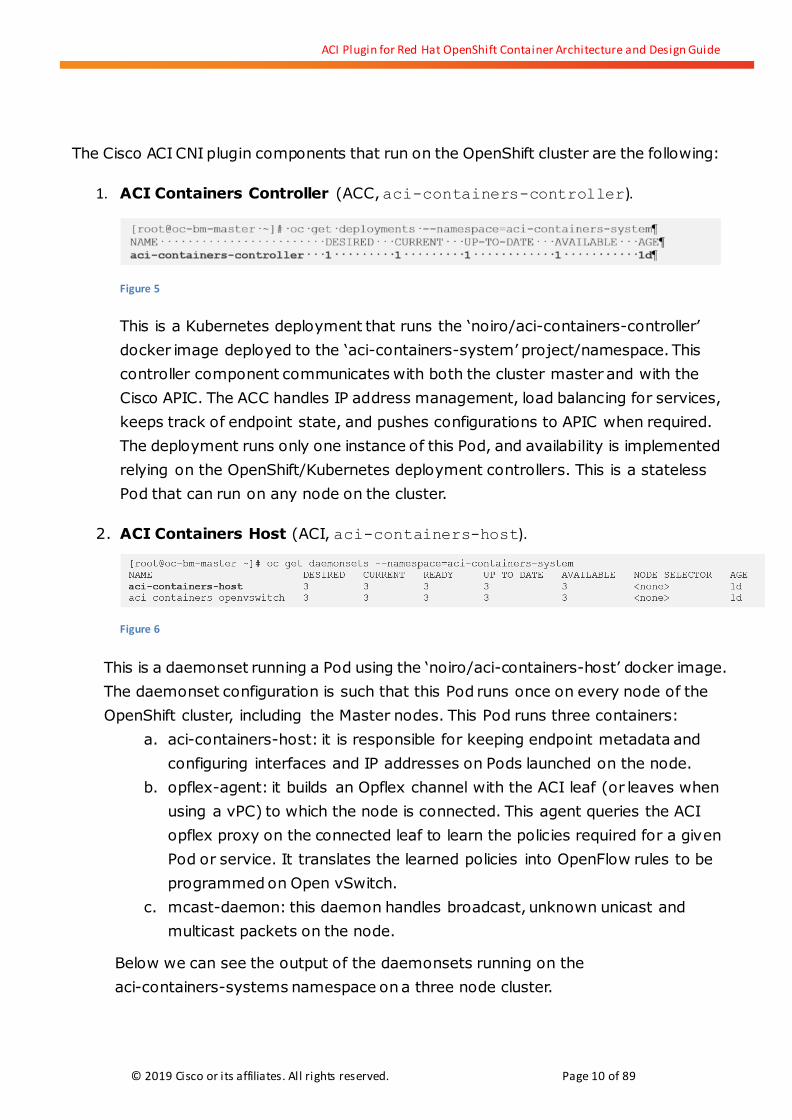
5. Cisco ACI CNI Plugin for OpenShift Architecture
The Cisco ACI CNI Plugin for OpenShift Container Platform provides integration between
the APIC controller and one or more OpenShift clusters connected to a Cisco ACI fabric.
This integration is implemented across two main functional areas:
1. The Cisco ACI CNI plugin extends the ACI fabric capabilities to OpenShift clusters
in order to provide IP Address Management, networking, load balancing and
security functions for OpenShift workloads. The Cisco ACI CNI plugin connects all
OpenShift Pods to the integrated VXLAN overlay provided by Cisco ACI.
2. The Cisco ACI CNI Plugin models the entire OpenShift cluster as a VMM Domain on
the Cisco APIC. This provides APIC with access to the inventory of resources of the
OpenShift cluster, including the number of OpenShift nodes, OpenShift
namespaces, services, deployments, Pods, their IP and MAC addresses, interfaces
they are using, etc. APIC uses this information to automatically correlate physical
and virtual resources in order to simplify operations.
The ACI CNI plugin is designed to be transparent for OpenShift developers and
administrators and to integrate seamlessly from an operational standpoint. One of the
main advantages of using the Cisco ACI CNI plugin for Red Hat OpenShift Container
Platform is to allow applications running on OpenShift to communicate with applications
running in other form factors such as bare metal, Virtual Machines or other container
clusters, without constraints or performance bottlenecks. Simply map multiple domain
types to the EPG of your choice and you have a mixed-workload environment in a matter
of seconds! ACI takes care of bridging and routing VxLAN to VLAN, VxLAN to VxLAN and
VLAN to VLAN automatically.
5.1. ACI CNI Plugin Components
The Cisco ACI CNI Plugin for Red Hat OpenShift Container Platform requires certain
configuration steps to be performed on the Cisco ACI fabric and running several
components as Pods on the OpenShift Cluster. Note that the deployment of those Pods as
well as the required ACI configuration is automated to a large extent by tools provided by
Cisco on cisco.com. Some of these components interact with functions implemented by
processes running on the Cisco APIC or on the ACI leaf switches.
ACI Plugin for Red Hat OpenShift Container Architecture and Design Guide
© 2019 Cisco or its affiliates. All rights reserved. Page 10 of 89
The Cisco ACI CNI plugin components that run on the OpenShift cluster are the following:
1. ACI Containers Controller (ACC, aci-containers-controller).
Figure 5
This is a Kubernetes deployment that runs the ‘noiro/aci-containers-controller’
docker image deployed to the ‘aci-containers-system’ project/namespace. This
controller component communicates with both the cluster master and with the
Cisco APIC. The ACC handles IP address management, load balancing for services,
keeps track of endpoint state, and pushes configurations to APIC when required.
The deployment runs only one instance of this Pod, and availability is implemented
relying on the OpenShift/Kubernetes deployment controllers. This is a stateless
Pod that can run on any node on the cluster.
2. ACI Containers Host (ACI, aci-containers-host).
Figure 6
This is a daemonset running a Pod using the ‘noiro/aci-containers-host’ docker image.
The daemonset configuration is such that this Pod runs once on every node of the
OpenShift cluster, including the Master nodes. This Pod runs three containers:
a. aci-containers-host: it is responsible for keeping endpoint metadata and
configuring interfaces and IP addresses on Pods launched on the node.
b. opflex-agent: it builds an Opflex channel with the ACI leaf (or leaves when
using a vPC) to which the node is connected. This agent queries the ACI
opflex proxy on the connected leaf to learn the policies required for a given
Pod or service. It translates the learned policies into OpenFlow rules to be
programmed on Open vSwitch.
c. mcast-daemon: this daemon handles broadcast, unknown unicast and
multicast packets on the node.
Below we can see the output of the daemonsets running on the
aci-containers-systems namespace on a three node cluster.

ACI Plugin for Red Hat OpenShift Container Architecture and Design Guide
© 2019 Cisco or its affiliates. All rights reserved. Page 11 of 89
3. ACI Containers Open vSwitch (ACI, aci-containers-openvswitch).
Figure 7
This is another daemonset configured to run on every node in the cluster instance of
a Pod using the ‘noiro/aci-containers-openvswitch’ docker image. The node’s Open
vSwitch uses this Pod as the control-plane only interface to program the required
security policies, such as Kubernetes Network Policies or ACI Contracts.
The ACI Pods connect to the host local network. All other Pods in the cluster connect to
opflex-configured networks. The ACI CNI plugin adds a configuration file under
/etc/cni/net.d/ as follows (note, version numbering may change):
Figure 8

ACI Plugin for Red Hat OpenShift Container Architecture and Design Guide
© 2019 Cisco or its affiliates. All rights reserved. Page 12 of 89
In addition to the components running on the OpenShift cluster, there are some functions
that are implemented on APIC and on the ACI fabric.
1. ACI VMM Manager. This process runs on the APIC cluster and communicates with
the ACI Containers Controller to receive required configuration, such as Network
Policies configured via Kubernetes as well as to learn about endpoints created or
deleted on the OpenShift Cluster. The VMM object model for OpenShift represents
many objects, such as namespaces, deployments, services and Pods. The VMM
manager inventory is key to correlating information between the OpenShift cluster,
the Open vSwitch and the Physical Fabric.
2. ACI Leaf Opflex Proxy. This process runs on the ACI leaf switches to scale out
policy propagation to the connected nodes. When new Pods are launched by
whatever means (a new deployment, or a scale out of an existing one), the ACI CNI
Plugin components provides its interface and IP address configuration. In addition,
they must know to which EPG the Pod must be connected and which security
policies must be configured. This information exists on the APIC cluster. However,
to avoid the opflex agent of every node querying the APIC directly, a two-tier scale
out model is used. The opflex agent running on the node on the aci-containers-host
Pod queries the ACI leaf to which it is connected. If the leaf has not received policy
for the endpoint, it queries the APIC, transfers the result to the opflex agent of the
node, caches the response, and implements any necessary configurations on the
leaf, such as SVI and VRF, contracts if required, etc. The next time a Pod connects
that requires the same policies, the answer to the opflex agent comes directly from
the leaf.
When the OpenShift nodes receive configuration from the leaf via opflex, the opflex agent
performs all required programming on the Open vSwitch of the node to implement the
required network and security policies. This includes routing configuration, so the first
hop router for every OpenShift Pod is always the local Open vSwitch of the node to which
it is connected. The opflex agent implements other features in software on Open vSwitch .
In particular, opflex programs Open vSwitch to perform distributed load balancing in order
to implement ClusterIP services, as well as to run a stateful distributed firewall to
implement Kubernetes Network Policies and stateless distributed firewall for ACI
Contracts. In section 5.4 we explain how these features are implemented.
ACI Plugin for Red Hat OpenShift Container Architecture and Design Guide
© 2019 Cisco or its affiliates. All rights reserved. Page 13 of 89
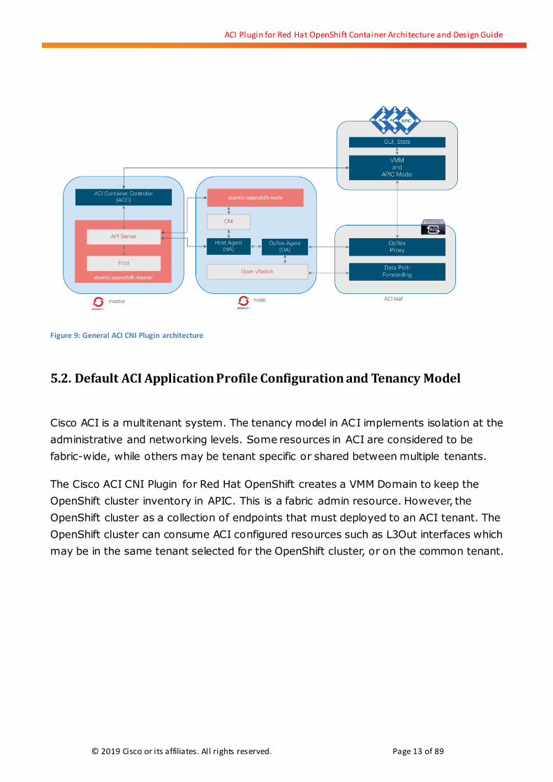
Figure 9: General ACI CNI Plugin architecture
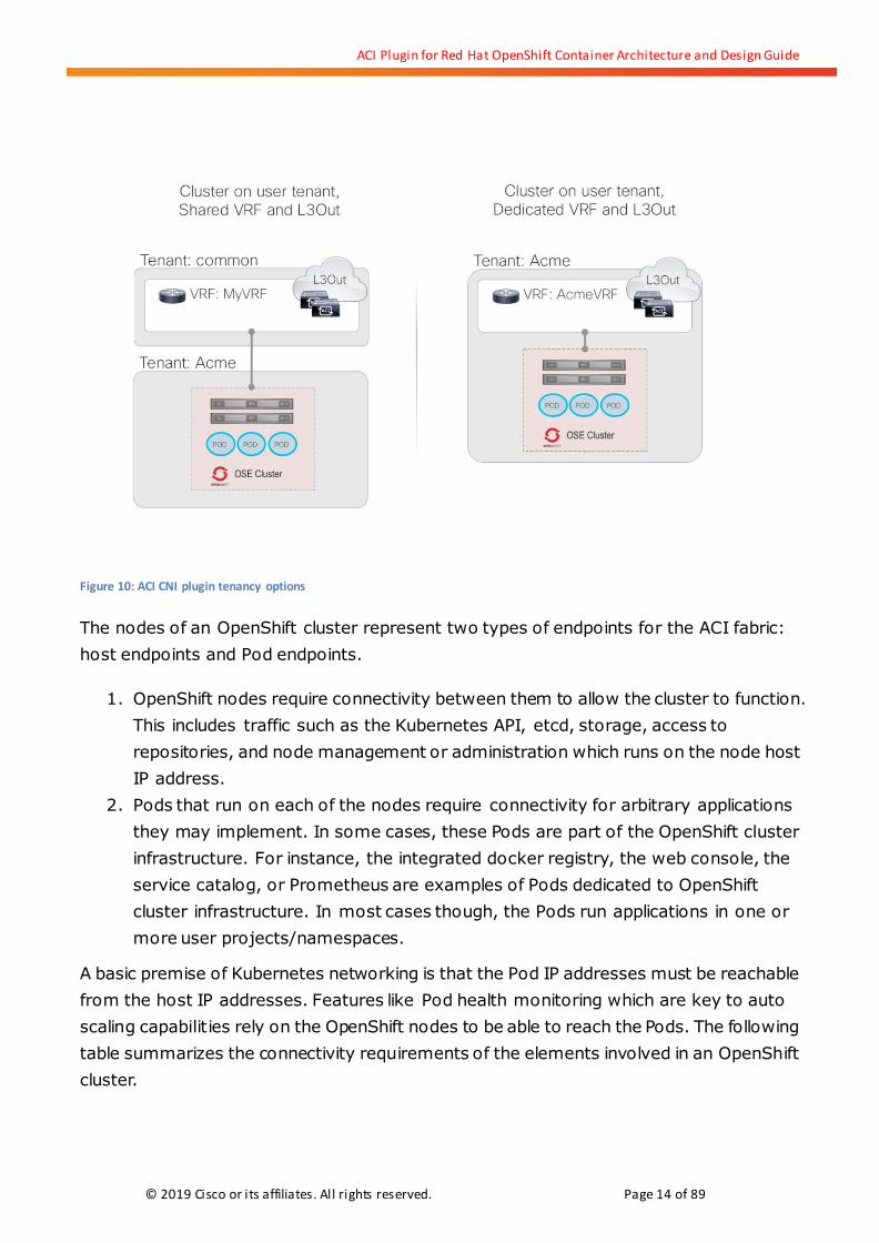
5.2. Default ACI Application Profile Configuration and Tenancy Model
Cisco ACI is a multitenant system. The tenancy model in ACI implements isolation at the
administrative and networking levels. Some resources in ACI are considered to be
fabric-wide, while others may be tenant specific or shared between multiple tenants.
The Cisco ACI CNI Plugin for Red Hat OpenShift creates a VMM Domain to keep the
OpenShift cluster inventory in APIC. This is a fabric admin resource. However, the
OpenShift cluster as a collection of endpoints that must deployed to an ACI tenant. The
OpenShift cluster can consume ACI configured resources such as L3Out interfaces which
may be in the same tenant selected for the OpenShift cluster, or on the common tenant.
ACI Plugin for Red Hat OpenShift Container Architecture and Design Guide
© 2019 Cisco or its affiliates. All rights reserved. Page 14 of 89
Figure 10: ACI CNI plugin tenancy options
The nodes of an OpenShift cluster represent two types of endpoints for the ACI fabric:
host endpoints and Pod endpoints.
1. OpenShift nodes require connectivity between them to allow the cluster to function.
This includes traffic such as the Kubernetes API, etcd, storage, access to
repositories, and node management or administration which runs on the node host
IP address.
2. Pods that run on each of the nodes require connectivity for arbitrary applications
they may implement. In some cases, these Pods are part of the OpenShift cluster
infrastructure. For instance, the integrated docker registry, the web console, the
service catalog, or Prometheus are examples of Pods dedicated to OpenShift
cluster infrastructure. In most cases though, the Pods run applications in one or
more user projects/namespaces.
A basic premise of Kubernetes networking is that the Pod IP addresses must be reachable
from the host IP addresses. Features like Pod health monitoring which are key to auto
scaling capabilities rely on the OpenShift nodes to be able to reach the Pods. The following
table summarizes the connectivity requirements of the elements involved in an OpenShift
cluster.
ACI Plugin for Red Hat OpenShift Container Architecture and Design Guide
© 2019 Cisco or its affiliates. All rights reserved. Page 15 of 89
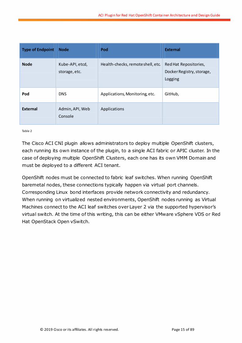
Type of Endpoint Node Pod External
Node Kube-API, etcd,
storage, etc.
Health-checks, remote shell, etc. Red Hat Repositories,
Docker Registry, storage,
Logging
Pod DNS Applications, Monitoring, etc. GitHub,
External Admin, API, Web
Console
Applications
Table 2
The Cisco ACI CNI plugin allows administrators to deploy multiple OpenShift clusters,
each running its own instance of the plugin, to a single ACI fabric or APIC cluster. In the
case of deploying multiple OpenShift Clusters, each one has its own VMM Domain and
must be deployed to a different ACI tenant.
OpenShift nodes must be connected to fabric leaf switches. When running OpenShift
baremetal nodes, these connections typically happen via virtual port channels.
Corresponding Linux bond interfaces provide network connectivity and redundancy.
When running on virtualized nested environments, OpenShift nodes running as Virtual
Machines connect to the ACI leaf switches over Layer 2 via the supported hypervisor’s
virtual switch. At the time of this writing, this can be either VMware vSphere VDS or Red
Hat OpenStack Open vSwitch.
ACI Plugin for Red Hat OpenShift Container Architecture and Design Guide
© 2019 Cisco or its affiliates. All rights reserved. Page 16 of 89
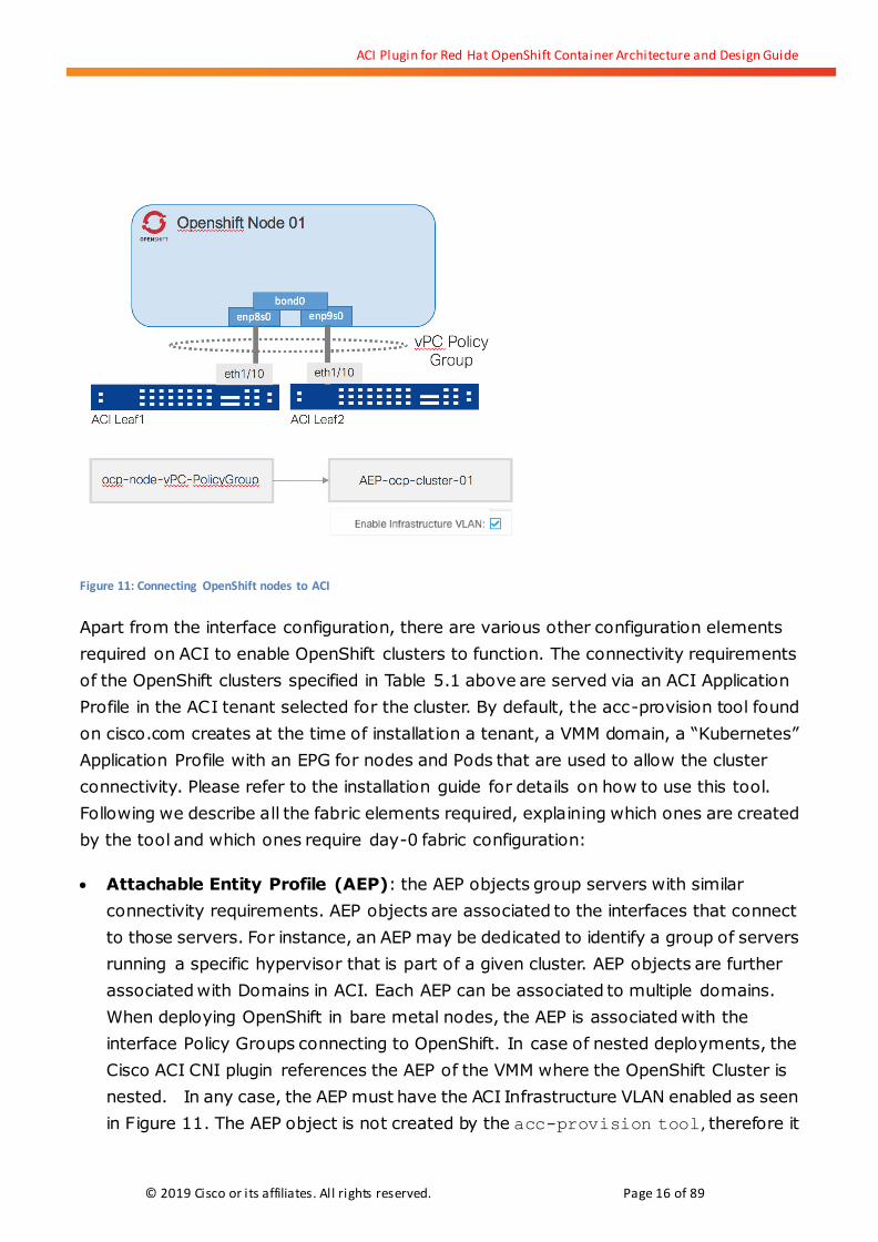
Figure 11: Connecting OpenShift nodes to ACI
Apart from the interface configuration, there are various other configuration elements
required on ACI to enable OpenShift clusters to function. The connectivity requirements
of the OpenShift clusters specified in Table 5.1 above are served via an ACI Application
Profile in the ACI tenant selected for the cluster. By default, the acc-provision tool found
on cisco.com creates at the time of installation a tenant, a VMM domain, a “Kubernetes”
Application Profile with an EPG for nodes and Pods that are used to allow the cluster
connectivity. Please refer to the installation guide for details on how to use this tool.
Following we describe all the fabric elements required, explaining which ones are created
by the tool and which ones require day-0 fabric configuration:
Attachable Entity Profile (AEP): the AEP objects group servers with similar
connectivity requirements. AEP objects are associated to the interfaces that connect
to those servers. For instance, an AEP may be dedicated to identify a group of servers
running a specific hypervisor that is part of a given cluster. AEP objects are further
associated with Domains in ACI. Each AEP can be associated to multiple domains.
When deploying OpenShift in bare metal nodes, the AEP is associated with the
interface Policy Groups connecting to OpenShift. In case of nested deployments, the
Cisco ACI CNI plugin references the AEP of the VMM where the OpenShift Cluster is
nested. In any case, the AEP must have the ACI Infrastructure VLAN enabled as seen
in Figure 11. The AEP object is not created by the acc-provision tool, therefore it

ACI Plugin for Red Hat OpenShift Container Architecture and Design Guide
© 2019 Cisco or its affiliates. All rights reserved. Page 17 of 89
is part of the day-0 configuration performed by a fabric administrator or as part of the
automation workflow used to set up a new cluster. You provide the name of the AEP to
the acc-provision tool which then takes care of binding the appropriate domain(s) to
the AEP, as well as creating VxLAN pools and static path bindings at the EPG level to
ensure node to node connectivity.
OpenShift Cluster Physical Domain (pdom). The physical domain profile stores the
physical resources (ports and port-channels) and encapsulation resources
(VLAN/VXLAN) that are used for endpoint groups associated with this domain. This
domain is created by the acc-provision tool, named as <cluster-name>-pdom and
associated with the indicated AEP. The domain also has an associated VLAN pool with
the VLANs that are used for connecting nodes (kubeapi_vlan in the acc-provision
tool configuration file) and external load balancer services (service_vlan in the
acc-provision tool configuration file).
Figure 12: View of OpenShift VMM Domain in APIC

ACI Plugin for Red Hat OpenShift Container Architecture and Design Guide
© 2019 Cisco or its affiliates. All rights reserved. Page 18 of 89
Figure 13: VLAN pools used by OpenShift VMM domain
OpenShift Cluster VMM Domain (vmmdom): the VMM domain helps APIC dynamically
learn about new endpoints that are connected to the fabric via a managed virtual
switch, in this case, the Opflex-managed Open vSwitch. The VMM Domain is named as
per the tenant where the cluster is deployed. It has a multicast pool and optionally a
VLAN pool associated, if the CNI plugin is configured to use VLANs instead of VXLAN.
Figure 14: View of OpenShift VMM Domain showing namespaces
Tenant: as mentioned before, when building an OpenShift cluster connected to ACI
using the Cisco ACI CNI Plugin, the cluster must be associated with an ACI tenant. The
ACI Plugin for Red Hat OpenShift Container Architecture and Design Guide
© 2019 Cisco or its affiliates. All rights reserved. Page 19 of 89
cluster can be deployed to a new tenant or to an existing one. If the tenant specified
does not exists, the acc-provisioning tool creates it.
VRF: this is the routing domain that is used for the subnets of the OpenShift Cluster
endpoints, both node and Pod addresses. This object is not created by the
acc-provisioning tool. It can be created on the cluster tenant or else on the
common tenant.
L3Out Interface and associated External EPG(s): this is the interface used for
communication between the OpenShift cluster any and endpoints not connected
directly to the fabric. This interface and at least one External EPG must be created in
the selected VRF as part of the day-0 configuration. The ACI CNI plugin may create
additional external EPGs on this L3Out interface during normal cluster operation for
exposed external OpenShift services. You provide the name of the L3Out and an
external EPG to acc-provision which then creates the appropriate contracts between
Pods EPGs and the L3Out EPG.
Bridge Domains: Bridge Domains are L2 constructs with associated subnets that
belong to a VRF. They are implemented as distributed Switch Virtual Interfaces (SVI)
that are automatically configured as required on the ACI fabric. For the Cisco ACI CNI
plugin to function, three Bridge Domains (BDs) are required and configured by the
acc-provision:
o kube-node-bd is configured on the tenant selected to deploy the OpenShift
cluster. It is associated to the same VRF used for the L3Out. This can be a VRF
that exists in the cluster tenant, or else on the common tenant. The BD is
automatically associated to the L3Out interface. This BD is configured with the
subnet used to assign host IP addresses to the OpenShift cluster nodes.
o kube-pod-bd is also configured on the tenant of the OpenShift cluster and it is
associated with the same VRF of the L3Out. This BD is not associated to the
L3Out by default. If it is required for Pods to access external fabric addresses, it
is necessary to associate the BD to the L3Out (via GUI, CLI, Ansible Playbook,
etc.). One example where this is required is if Pods require accessing Github
repositories.
o bd-kubernetes-service is different from the previous two. This BD is created
in the tenant where the L3Out exists. This means that if using a shared L3Out in
common tenant, this BD is created in tenant common. This BD is not created by
the acc-provision-tool but does not require an administrator to create it.
Instead, it is created by the aci-containers-controller when it comes

ACI Plugin for Red Hat OpenShift Container Architecture and Design Guide
© 2019 Cisco or its affiliates. All rights reserved. Page 20 of 89
oline. This BD has a subnet internally used for the two-stage PBR load balancing
feature.
Kubernetes Application Profile. An Application Profile is a collection of Endpoint
Groups (EPG) and their communication policies specified using ACI Contracts. The
Kubernetes Application Profile enables connectivity for all nodes and Pods in the
OpenShift cluster and is created by the acc-provision tool in the tenant selected for
the cluster. The Application Profile includes the following objects:
o kube-nodes EPG. This EPG connects the host IP address of the nodes of the
OpenShift cluster and is associated to the kube-node-bd Bridged Domain. It is
mapped to the Physical Domain created by acc-provision tool by associating it
at the AEP level, so static path bindings are not required when adding new
nodes to the cluster.
o kube-default EPG. This EPG is mapped to the OpenShift cluster VMM domain
and associated to the kube-pod-bd Bridge Domain. By default, all Pods
launched in the OpenShift cluster is connected to this EPG, unless they are
annotated for the plugin to do otherwise.
o kube-system EPG. This EPG is also mapped to the OpenShift cluster VMM
domain and associated to the kube-pod-bd Bridge Domain. All Pods on the
kube-system namespace are placed on this EPG. Note that this EPG is only used
for pure Kubernetes deployments, it has no relevance in OpenShift
deployments.
o Contracts. In ACI, contracts define security policies that implement filters that
control what communications are allowed. By default ACI implements a
white-list policy model, so only communications explicitly define are enabled
between different EPGs. For OpenShift to function, various type of traffic must
be allowed, such as DNS, kube-api, health-checks, etcd, etc. The
acc-provision tool creates basic contracts to enable the cluster to function.

ACI Plugin for Red Hat OpenShift Container Architecture and Design Guide
© 2019 Cisco or its affiliates. All rights reserved. Page 21 of 89
Figure 15: ACI Kubernetes Application Profile
Cluster L4-7 Device. The Cisco ACI CNI Plugin provides a cloud controller
implementation to leverage the ACI fabric for L4 load balancing for external
LoadBalancer services. Each OpenShift cluster is represented as a Logical Load
Balancer and has an associated Service Graph template that leverages Cisco ACI
Policy Based Redirection (PBR) capabilities. The the acc-provision tool creates the
device and Service Graph template on the tenant that owns the VRF and L3Out.
Figure 16: ACI Logical L4 Load Balancer for OpenShift cluster

ACI Plugin for Red Hat OpenShift Container Architecture and Design Guide
© 2019 Cisco or its affiliates. All rights reserved. Page 22 of 89
Figure 17: ACI Logical L4 Load Balancer Service Graph Template for OpenShift cluster
The acc-provision tool creates only the basic three EPGs and contracts required for basic
operation of an OpenShift cluster. It is possible that additional EPGs and contracts are
required. For instance, if the OpenShift cluster uses the Service Catalog, it is necessary to
add additional configuration to the Kubernetes application in order to allow the
kube-default EPG to consume the etcd contract that allows tcp/2379. You need a contract
to the OpenShift ingress router.
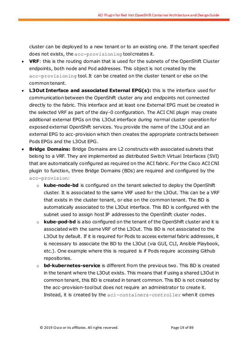
The following graphic illustrates the various components once deployed, showing a single
OpenShift master and single node. For illustration purposes, we show the OpenShift
router Pod on the first node and the registry Pod on the master. In both cases, they are
connected to the kube-default EPG, extended to Open vSwitch by means of OpFlex. The
aci-containers-controller Pod is shown running on the node. Both master and node run
aci-containers-host and aci-containers-openvswitch (the name has been abbreviated for
illustration purposes).
ACI Plugin for Red Hat OpenShift Container Architecture and Design Guide
© 2019 Cisco or its affiliates. All rights reserved. Page 23 of 89
Figure 18: Diagram view of nodes with ACI CNI plugin and EPG model
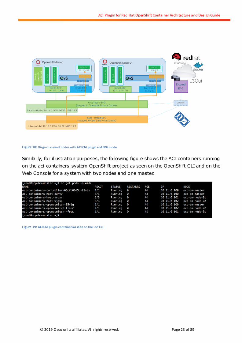
Similarly, for illustration purposes, the following figure shows the ACI containers running
on the aci-containers-system OpenShift project as seen on the OpenShift CLI and on the
Web Console for a system with two nodes and one master.
Figure 19: ACI CNI plugin containers as seen on the ‘oc’ CLI

ACI Plugin for Red Hat OpenShift Container Architecture and Design Guide
© 2019 Cisco or its affiliates. All rights reserved. Page 24 of 89
Figure 20: ACI CNI plugin containers as seen on the Web Console
5.3. Managing the address spaces for the ACI CNI Plugin
A working OpenShift cluster requires IP addresses for various functions. Every node
requires at least one IP address for the host TCP/IP stack that is used for running the API,
accessing repositories, registries, etc. It is possible that an additional interface and IP is
used for Out-of-Band Management. Then, the cluster needs to be able to assign IP
addresses to Pods, internal services and external services. Prior to the OpenShift cluster
installation, it is important to conduct IP address planning and decide which subnets or
Classless Inter-Domain Routing (CIDR) address spaces are used for various functions.
When using the Cisco ACI CNI plugin, the IP addresses for Pods and services are provided
by the plugin and in general all subnets must be configured in the fabric.
The following table summarizes the various subnets or CIDRs required, including the
parameter used by the OpenShift installer to refer to them and the corresponding Cisco
ACI CNI plugin parameter and associated fabric configuration.

ACI Plugin for Red Hat OpenShift Container Architecture and Design Guide
© 2019 Cisco or its affiliates. All rights reserved. Page 25 of 89
OpenShift Install Parameter ACI Plugin Parameter Fabric Configuration
osm_cluster_network_cidr
This is the network from which pod IPs are assigned. This network
block should be a private block and must not conflict with existing
network blocks in your infrastructure to which pods, nodes, or the
master may require access .
pod_subnet This subnet is configured under
kube-pod-bd Bridge Domain.
OpenShift_portal_net
This variable configures the subnet in which internal services are
created within the OpenShift Container Platform. This network block
should be private and must not conflict with any existing network
blocks in your infrastructure to which pods, nodes, or the master may
require access to, or the installation will fail. This value overrides the
ACI CNI plugin parameter.
n/a This subnet is not configured on
the fabric, nor is visible at the
leaf level. It is used only on
Opflex-OVS configurations for
ClusterIP load balancing.
OpenShift_master_ingress_ip_network_cidr
For OpenShift, the external IP used for the LoadBalancer service type is
automatically chosen from the subnet pool specified in the
igressIPNetworkCIDR configuration in the
/etc/origin/master/master-config.yaml file. This subnet should match
the extern_dynamic property configured in the input file provided to
acc_provision script. If a specific IP is desired from this subnet pool, it
can be assigned to the "loadBalancerIP" property in the LoadBalancer
service spec. For more details refer to OpenShift documentation here:
https://docs.openshift.com/container-platform/3.9/admin_guide/tc
p_ingress_external_ports.html#unique-external-ips-ingress-traffic-co
nfigure-cluster
extern_dynamic This subnet is not configured
under any BD. Endpoints from
this subnet are configured under
external EPGs.
OpenShift_master_external_ip_network_cidrs
ExternalIPNetworkCIDRs controls what values are acceptable for the
service external IP field but do not work with type LoadBalancer. See
https://kubernetes.io/docs/concepts/services-networking/service/#
external-ips
extern_static The extern_static parameter in
acc-provision is not used in
OpenShift.
Table 3
ACI Plugin for Red Hat OpenShift Container Architecture and Design Guide
© 2019 Cisco or its affiliates. All rights reserved. Page 26 of 89
Be aware that the IP range you pick for Pods should be routable within your organization. ACI
does not perform source NAT when Pods are egressing the fabric. Pods egress the fabric using their
assigned IP address directly. You can attach a NAT router to the ACI L3Out of course, but keep in
mind NAT is not a function provided by ACI natively. Plan accordingly.
Once deployed and running, the configuration for the Cisco ACI CNI plugin for Red Hat
OpenShift is kept on a configmap object in the aci-containers-system project. This object
keeps track of the APIC IP addresses, the user account and key used to communicate with
APIC, the subnets used for Pods and services, etc. In other words, the container controller
is said to be stateless.
5.4. Cisco ACI CNI Plugin Feature Deep-Dive
The Cisco ACI CNI Plugin provides all networking and security requirements for the
OpenShift cluster. When using the Cisco ACI CNI plugin there is no need to use egress
routers, however ingress routers to expose routes (Layer 7 Load Balancing) are still
required.
The key features of the Cisco ACI CNI Plugin are:
IP Address Management and Virtual Networking for Pods and Services
Distributed Routing and Switching with integrated VXLAN overlays implemented fabric-wide and
on Open vSwitch
Distributed Load Balancing for ClusterIP services
Hardware-accelerated Load Balancing for LoadBalancer services
Distributed firewall for implementing Network Policies
EPG-level segmentation for Kubernetes objects using annotations
Consolidated visibility of Kubernetes networking via APIC VMM Integration
In this section, we explain in detail how each functionality enabled by the ACI CNI Plugin for Red Hat
OpenShift works.

ACI Plugin for Red Hat OpenShift Container Architecture and Design Guide
© 2019 Cisco or its affiliates. All rights reserved. Page 27 of 89
5.4.1. IP Address Management and Virtual Networking for Pods and Services
A basic responsibility of the CNI plugin is to create the interfaces on the Pods, connect
them to a virtual network on the host and assign the Pod’s interface an IP address as well
as configure it with the necessary routes. In the case of the Cisco ACI CNI plugin, the
default route on the Pods points to the distributed default gateway provided by the ACI
fabric on the kube-node-bd Bridge Domain.
The IPAM configuration for the ACI CNI plugin is dictated by the configuration files placed
on /etc/cni/net.d/10-opflex-cni.conf. When using the Cisco ACI CNI plugin, this file is
present on each node and looks as follows:
Figure 21
The network type for Pods is set to ‘opflex-agent-cni’ and specifies the binary that must be
executed when required. The ‘ipam’ to be used for the Pods is set to be done by the
‘opflex-agent-cni-ipam’.
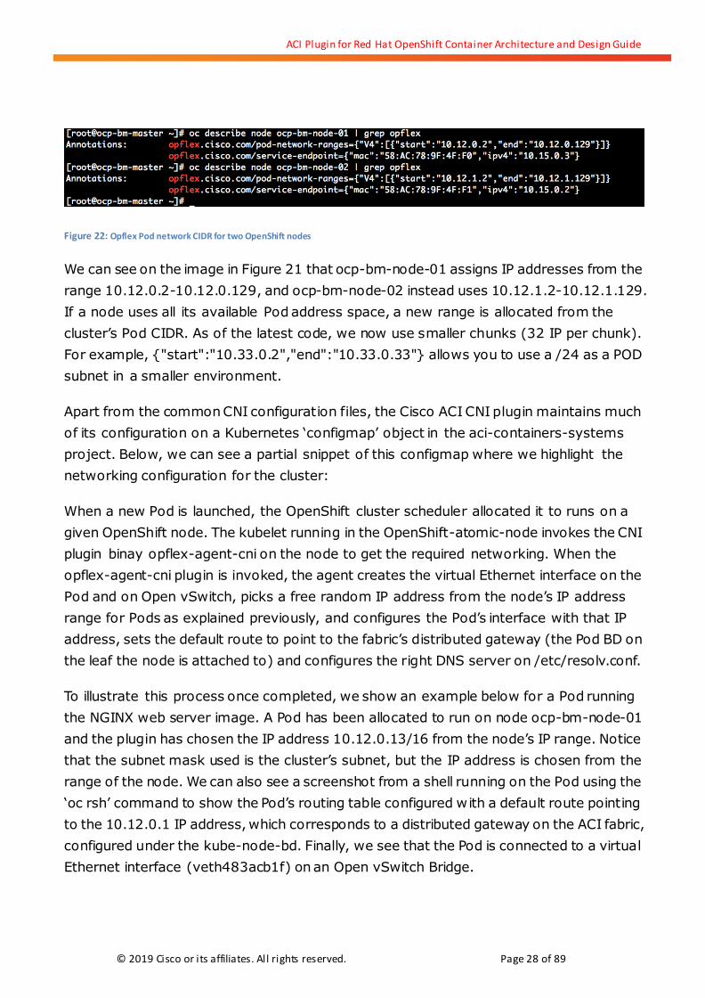
Each OpenShift node has one or more ranges of IP addresses assigned from the
pod_subnet (osm_cluster_network_cidr) CIDR available for the opflex agent running
on the node. The agent assigns IP addresses for Pods from these ranges. This can be seen
on the opflex annotations of the node, as shown below for the first two nodes
(ocp-bm-node-01 and ocp-bm-node-02) of a cluster where
osm_cluster_network_cidr = 10.12.0.0/16:
ACI Plugin for Red Hat OpenShift Container Architecture and Design Guide
© 2019 Cisco or its affiliates. All rights reserved. Page 28 of 89
Figure 22: Opflex Pod network CIDR for two OpenShift nodes
We can see on the image in Figure 21 that ocp-bm-node-01 assigns IP addresses from the
range 10.12.0.2-10.12.0.129, and ocp-bm-node-02 instead uses 10.12.1.2-10.12.1.129.
If a node uses all its available Pod address space, a new range is allocated from the
cluster’s Pod CIDR. As of the latest code, we now use smaller chunks (32 IP per chunk).
For example, {"start":"10.33.0.2","end":"10.33.0.33"} allows you to use a /24 as a POD
subnet in a smaller environment.
Apart from the common CNI configuration files, the Cisco ACI CNI plugin maintains much
of its configuration on a Kubernetes ‘configmap’ object in the aci-containers-systems
project. Below, we can see a partial snippet of this configmap where we highlight the
networking configuration for the cluster:
When a new Pod is launched, the OpenShift cluster scheduler allocated it to runs on a
given OpenShift node. The kubelet running in the OpenShift-atomic-node invokes the CNI
plugin binay opflex-agent-cni on the node to get the required networking. When the
opflex-agent-cni plugin is invoked, the agent creates the virtual Ethernet interface on the
Pod and on Open vSwitch, picks a free random IP address from the node’s IP address
range for Pods as explained previously, and configures the Pod’s interface with that IP
address, sets the default route to point to the fabric’s distributed gateway (the Pod BD on
the leaf the node is attached to) and configures the right DNS server on /etc/resolv.conf.
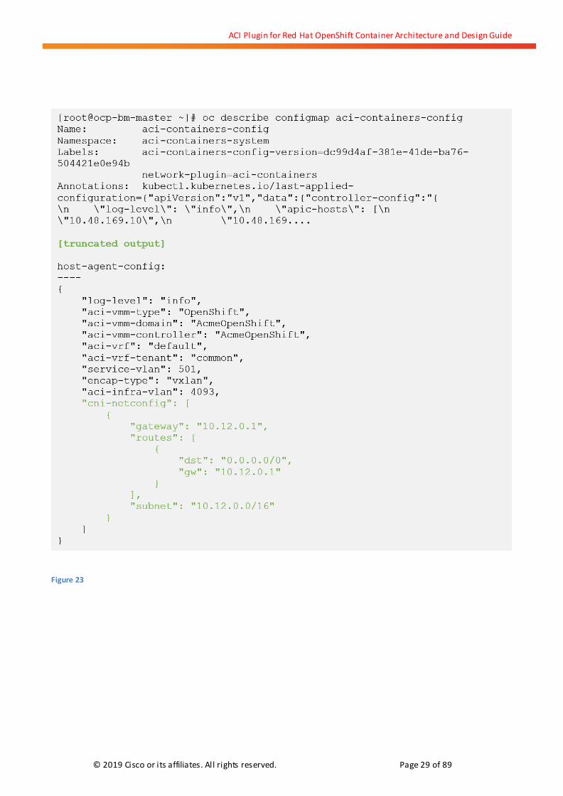
To illustrate this process once completed, we show an example below for a Pod running
the NGINX web server image. A Pod has been allocated to run on node ocp-bm-node-01
and the plugin has chosen the IP address 10.12.0.13/16 from the node’s IP range. Notice
that the subnet mask used is the cluster’s subnet, but the IP address is chosen from the
range of the node. We can also see a screenshot from a shell running on the Pod using the
‘oc rsh’ command to show the Pod’s routing table configured with a default route pointing
to the 10.12.0.1 IP address, which corresponds to a distributed gateway on the ACI fabric,
configured under the kube-node-bd. Finally, we see that the Pod is connected to a virtual
Ethernet interface (veth483acb1f) on an Open vSwitch Bridge.
ACI Plugin for Red Hat OpenShift Container Architecture and Design Guide
© 2019 Cisco or its affiliates. All rights reserved. Page 29 of 89
Figure 23
ACI Plugin for Red Hat OpenShift Container Architecture and Design Guide
© 2019 Cisco or its affiliates. All rights reserved. Page 30 of 89
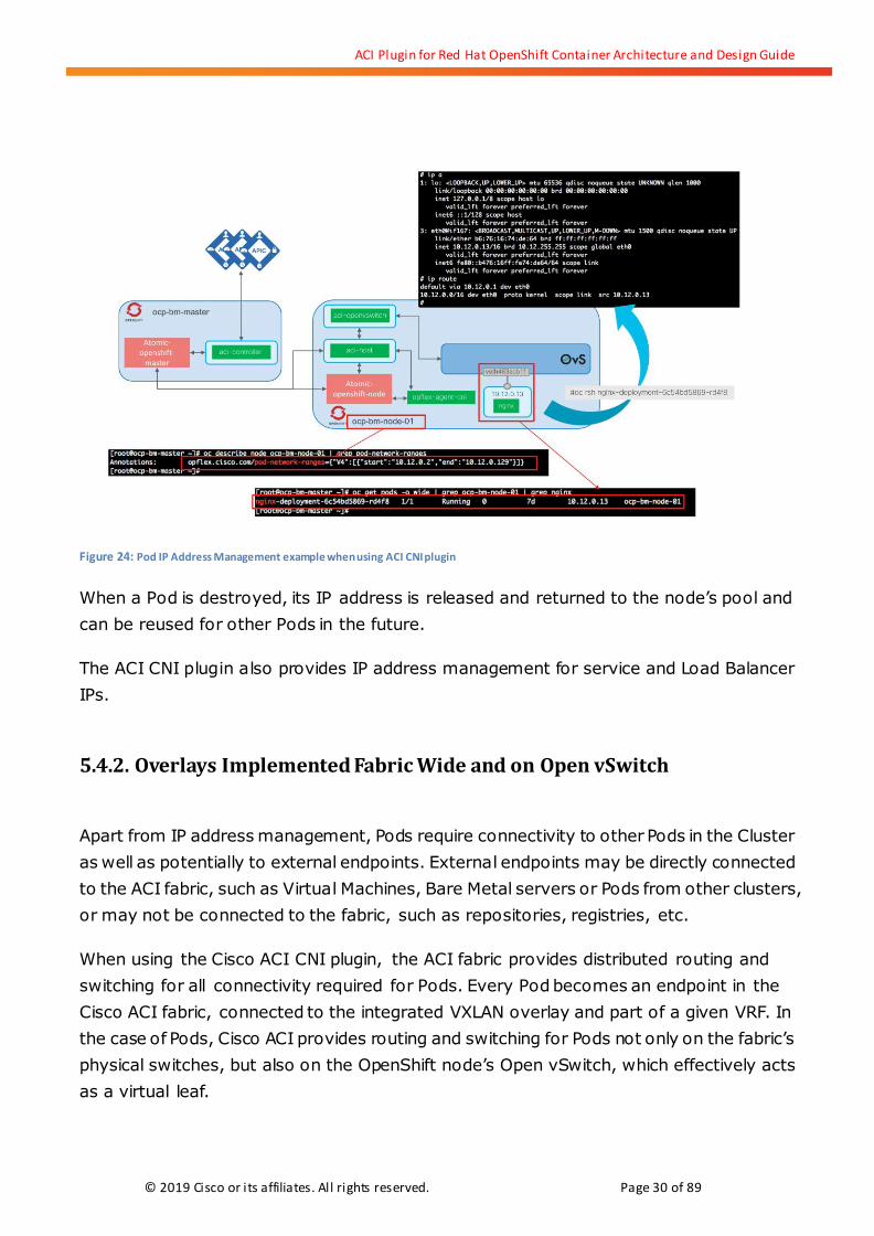
Figure 24: Pod IP Address Management example when using ACI CNI plugin
When a Pod is destroyed, its IP address is released and returned to the node’s pool and
can be reused for other Pods in the future.
The ACI CNI plugin also provides IP address management for service and Load Balancer
IPs.
5.4.2. Overlays Implemented Fabric Wide and on Open vSwitch
Apart from IP address management, Pods require connectivity to other Pods in the Cluster
as well as potentially to external endpoints. External endpoints may be directly connected
to the ACI fabric, such as Virtual Machines, Bare Metal servers or Pods from other clusters,
or may not be connected to the fabric, such as repositories, registries, etc.
When using the Cisco ACI CNI plugin, the ACI fabric provides distributed routing and
switching for all connectivity required for Pods. Every Pod becomes an endpoint in the
Cisco ACI fabric, connected to the integrated VXLAN overlay and part of a given VRF. In
the case of Pods, Cisco ACI provides routing and switching for Pods not only on the fabric’s
physical switches, but also on the OpenShift node’s Open vSwitch, which effectively acts
as a virtual leaf.

ACI Plugin for Red Hat OpenShift Container Architecture and Design Guide
© 2019 Cisco or its affiliates. All rights reserved. Page 31 of 89
But APIC does not need to program Open vSwitch directly. Instead, this task is delegated
to the opflex agent running on the node. The opflex agent learns information about the
Pod from the CNI integration with the OpenShift node, and queries the upstream ACI leaf
to learn the fabric required policy configuration, including the EPG, the VRF, and other
information. The opflex agent maintains an endpoint file in
/var/lib/opflex-agent-ovs/endpoints for each Pod. This file contains the information
required to connect the Pod to the ACI integrated overlay. We can see below the EP file for
the NGINX Pod of the example in Figure 23.
Figure 25
The EP file contains all relevant information to correctly configure Open vSwitch to
provide connectivity to the Pod. In particular, as seen in Figure 25, the opflex agent learns
to which EPG the Pod must be connected.

ACI Plugin for Red Hat OpenShift Container Architecture and Design Guide
© 2019 Cisco or its affiliates. All rights reserved. Page 32 of 89
Figure 26: Representation of the opflex agent and opflex proxy function
This model effectively extends the fabric routing and switching capabilities to the Open
vSwitch of the node. In Figure 26, we see a second Pod running the busybox image that
has been scheduled to the same node as our nginx Pod from previous examples.
Connections between these two Pods are switched locally on the Open vSwitch,
minimizing latency.
Figure 27: Local switching between Pods on the same node

ACI Plugin for Red Hat OpenShift Container Architecture and Design Guide
© 2019 Cisco or its affiliates. All rights reserved. Page 33 of 89
The first hop for routing or switching decisions for a Pod’s traffic is at the Open vSwitch of
the node. When traffic is not destined to a Pod local to the node, the traffic is encapsulated
with the Pod’s EPG encapsulation details, which can be a VLAN or VXLAN encapsulation
(per the configuration provided to acc-provision), and sent to the destination. Figure 27
shows the example where the busybox Pod is located on another node and traffic is
traversing the physical fabric.
Figure 28: Fabric switching between Pods on the different nodes
Routing to any subnet connected to the ACI fabric follows the same path from Figure 27,
of course assuming that traffic between different EPGs is allowed by having the
appropriate ACI contracts configured (such contracts are enforced by ACI in the Open
vSwitch and in the ACI leaf, as explained later in the document).
Routing to subnets external to the fabric is taken care of by ACI via L3Out interfaces. For
the ACI fabric to route traffic between local subnets and external prefixes reachable via an
L3Out interface, three things must be true:
The Bridge Domain where the subnet is configured must be associated with the
L3Out interface used to reach a given prefix.
The subnet configuration must have the flag “advertise externally” configured.
There must be a contract between an EPG associated with the Bridge Domain and
an external EPG associated with the L3Out interface.

ACI Plugin for Red Hat OpenShift Container Architecture and Design Guide
© 2019 Cisco or its affiliates. All rights reserved. Page 34 of 89
While the kube-node-bd is automatically associated to the L3Out used for the OpenShift
cluster at the time of running the acc-provision tool, kube-pod-bd is not. Similarly, the
kube-pod CIDR used to configure the Pod subnet is by default private to the VRF.
Figure 29: kube-pod-bd must be associated to the L3Out
If the Pods require access to external IP prefixes, the administrator must change the
configurations for the kube-pod-bd and subnets as per Figure 28 in order to enable the
subnet to be announced via the L3Out, assuming that it is configured to use dynamic
routing. This is a very frequent use case because Pods often need to pull content from
external repositories such as github. Once this is done, applications running on Pods can
access external prefixes routing via the ACI fabric L3Out. In Figure 29 we show this at a
high level where an application is accessing a Git service. Since it is very possible that the
kube-pod CIDR is not routable outside of the ACI infrastructure, NAT for this IP range
should be done at a router or firewall as shown in the figure below.

ACI Plugin for Red Hat OpenShift Container Architecture and Design Guide
© 2019 Cisco or its affiliates. All rights reserved. Page 35 of 89
Figure 30: Pods accessing external resources via L3Out
5.4.3. Distributed Load Balancer for ClusterIP
Each Pod has a unique IP address, but Pods are meant to be ephemeral by nature, so you
should not rely on the Pod’s IP address to connect to a given application component or tier.
Kubernetes provides ‘service’ objects to implement a persistent IP address to access a set
of Pods. The Service object has an associated endpoint object that tracks the Pods that
are backed by the service IP addresses, and therefore acts as an internal load balancer for
traffic to those Pods. Essentially, the service object identifies a set of Pods in order to
proxy connections towards them. The service object has an associated service endpoints
list that contains an updated list of all the Pods that the service can send traffic to.
Services are assigned an IP address and port pair and use a label selector to find all the
running containers that provide a certain network service on the given port. The most
common type of service IP address is of type “ClusterIP”. The ClusterIP is a persistent
virtual IP address that is used for load balancing traffic internal to the cluster. This is
usually considered East-West traffic, since it is traffic originating from Pods running in the
cluster to the service IP backed by Pods that also run in the cluster. Traffic sent to the
ClusterIP must be NAT’ed to the IP address of one of the Pods backing the service, which
sees the traffic coming from the originating Pod.
The Cisco ACI CNI plugin for Red Hat OpenShift implements everything required for
ACI Plugin for Red Hat OpenShift Container Architecture and Design Guide
© 2019 Cisco or its affiliates. All rights reserved. Page 36 of 89
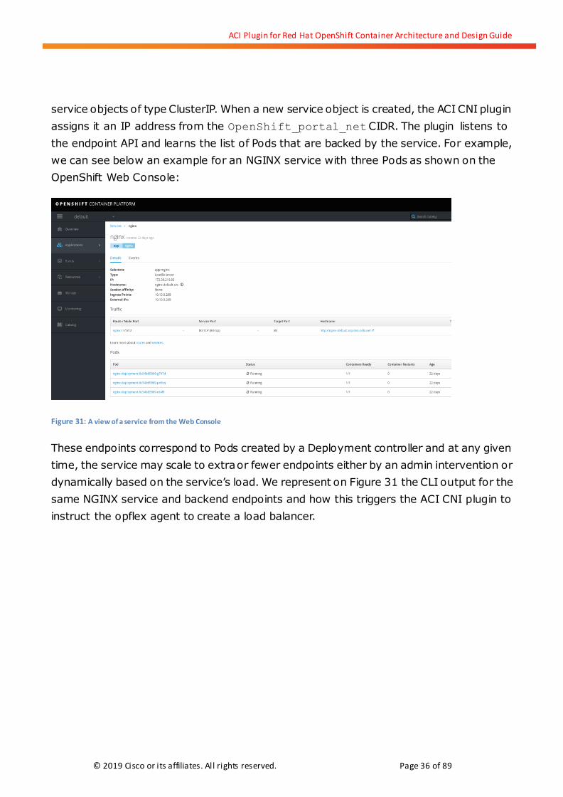
service objects of type ClusterIP. When a new service object is created, the ACI CNI plugin
assigns it an IP address from the OpenShift_portal_net CIDR. The plugin listens to
the endpoint API and learns the list of Pods that are backed by the service. For example,
we can see below an example for an NGINX service with three Pods as shown on the
OpenShift Web Console:
Figure 31: A view of a service from the Web Console
These endpoints correspond to Pods created by a Deployment controller and at any given
time, the service may scale to extra or fewer endpoints either by an admin intervention or
dynamically based on the service’s load. We represent on Figure 31 the CLI output for the
same NGINX service and backend endpoints and how this triggers the ACI CNI plugin to
instruct the opflex agent to create a load balancer.

ACI Plugin for Red Hat OpenShift Container Architecture and Design Guide
© 2019 Cisco or its affiliates. All rights reserved. Page 37 of 89
Figure 32: The APIC programs a distributed load balancer on OVS for ClusterIP
The plugin on every OpenShift node has access to all the required information and creates
a service endpoint file under /var/lib/opflex-agent-ovs/services and configure openflow
entries on the node’s Open vSwitch that capture traffic for the service ClusterIP IP
address and load balance it to the Pods that are backing the service. Below we can see an
example of the service endpoint file for the same NGINX service of the example above.

ACI Plugin for Red Hat OpenShift Container Architecture and Design Guide
© 2019 Cisco or its affiliates. All rights reserved. Page 38 of 89
Figure 33
Effectively, the Cisco ACI CNI plugin implements a distributed load balancer on Open
vSwitch in order to implement ClusterIP services. This is transparent to the cluster’s DNS
service discovery. Traffic from any Pod accessing the service ClusterIP and/or service
name is load balanced to the right Pods.

ACI Plugin for Red Hat OpenShift Container Architecture and Design Guide
© 2019 Cisco or its affiliates. All rights reserved. Page 39 of 89
Figure 34: The APIC programs a distributed load balancer on OVS for ClusterIP
ClusterIP service IP addresses are automatically associated with DNS entries on the
OpenShift cluster for service discovery purposes. The ACI CNI plugin is completely
transparent in this sense and OpenShift DNS-based service discovery works perfectly
fine.
5.4.4. Consolidated Visibility of Kubernetes Networking via APIC VMM
Integration
The VMM integration allows APIC to learn and model virtual endpoints as they connect to
the fabric. This is based on a control and management plane integration between the
APIC and the domain controller. When using the Cisco ACI CNI plugin, the VMM
integration is implemented through the aci-containers-controller and the opflex agent
running on each OpenShift node. Each OpenShift cluster running the Cisco ACI CNI plugin
represents a Container Domain, compDom class in the APIC object model, of type
OpenShift. Each node running an opflex agent represents an object of class opflexODev in
the APIC model with details of the physical path connecting it and the status of the node.
In Figure 34 we show a few combined screenshots that illustrate these concepts. The ‘oc
get nodes’ helps an OpenShift administrator list the nodes part of the cluster. The fabric

ACI Plugin for Red Hat OpenShift Container Architecture and Design Guide
© 2019 Cisco or its affiliates. All rights reserved. Page 40 of 89
administrator no longer has to see these nodes as just unknown servers connected to a
fabric switch. Instead, APIC has the inventory of nodes of the cluster and it is now easy for
the fabric administrator to immediately know the role of every server and where they are
in the physical fabric.
Figure 35: VMM integration provides fabric administrators with visibility
The VMM integration with OpenShift not only provides node-level visibility, but also
visibility into the Kubernetes model and endpoints. Each OpenShift project is effectively a
Kubernetes namespace which is mapped in the APIC object model to an object of class
compNameSpace. The following table summarizes the elements of the OpenShift cluster
modeled by the APIC VMM:
OpenShift object APIC object class Information
Project/Namespace compNameSpace Lis t of all namespaces and Pods running on them
Deployment compDeployment Lis t of deployments in a namespace, number of replicas and Pod details
ReplicaSet compReplicaSet Lis t of all replicasets for corresponding deployments along with Pod details
Service CompService Lis t of services with details of ports and protocols exposed and endpoints backing them.
Pod
compContGrp shows EPG, IP, Mac encapsulation, physical path, stats
opflexIDEp Lis t of Pods, tracking node allocation, physical and vi rtual network information, IP,
MAC, s tatistics, etc.
Table 4

ACI Plugin for Red Hat OpenShift Container Architecture and Design Guide
© 2019 Cisco or its affiliates. All rights reserved. Page 41 of 89
The main objective of the VMM integration is to facilitate operations. This is accomplished
by giving context to the fabric administrator, so that a network endpoint is no longer just
seen as a Mac address learnt on a switchport, physical or virtual, but instead can be
immediately associated to its IP address, role, format and location.
Figure 36: An OpenShift LoadBalancer service as seen in the VMM and object model
For instance, on Figure 35 we show a service object NGINX and associated endpoints as
seen by the OpenShift administrator on the ‘oc’ CLI. The fabric administrator can see the
same information using the APIC GUI and/or the Visore object browser, thus recognizing
that an IP address is part of a service object, and therefore intends to load balance to
other elements and immediately seeing those Pod elements along with its entire network
path: virtual port on Open vSwitch, encapsulation, labels, and EPG. By looking at the Pod
details the administrator can then see the node on which the Pod is running and correlate
the physical path with the virtual automatically without requiring external tools that are
both expensive and always outdated.
APIC can also gather statistics from the opflex agent. In Figure 36 we see a Pod, which is
represented in APIC as both a corresponding Pod object and its associated fabric endpoint
information, and the network traffic statistics collected by the opflex agent.

ACI Plugin for Red Hat OpenShift Container Architecture and Design Guide
© 2019 Cisco or its affiliates. All rights reserved. Page 42 of 89
Figure 37: VMM statistics for an OpenShift Pod network traffic
This is of course not in detriment of the OpenShift administrator tracking metrics using
their own tools, as seen in Figure 37 where we show the metrics seen on the OpenShift
web console for the same nginx Pod. Each administrator can use the information on the
tools they most commonly use.
Figure 38: Web Console statistics for an OpenShift Pod network traffic
ACI Plugin for Red Hat OpenShift Container Architecture and Design Guide
© 2019 Cisco or its affiliates. All rights reserved. Page 43 of 89
5.4.5. Distributed Hardware-Accelerated Load Balancer
When services provided by the cluster must be accessible to external endpoints,
Kubernetes provides a different type of service object: the LoadBalancer service. This
object calls a cloud controller that is plugin-specific and must create an external load
balancer to reach the service. While the ClusterIP address associated to a service is
internal to the cluster and only reachable by the cluster Pods, the LoadBalancer (External)
IP address is accessible externally.
The Cisco ACI CNI plugin provides IP address management for LoadBalancer objects as
well as a Layer4-level load balancer implemented on the fabric leaf switches using ACI
Policy Based Redirect (PBR).
The Cisco ACI CNI plugin chooses IP addresses for external services from the configured
OpenShift_master_ingress_ip_network_cidr2 to provide them to service objects
configured as type LoadBalancer. This CIDR is not configured on any Bridge Domain in the
ACI fabric.
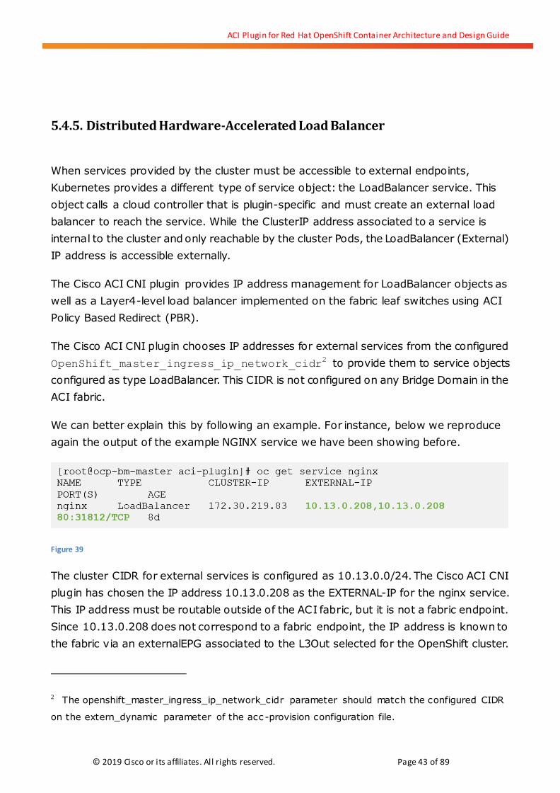
We can better explain this by following an example. For instance, below we reproduce
again the output of the example NGINX service we have been showing before.
Figure 39
The cluster CIDR for external services is configured as 10.13.0.0/24. The Cisco ACI CNI
plugin has chosen the IP address 10.13.0.208 as the EXTERNAL-IP for the nginx service.
This IP address must be routable outside of the ACI fabric, but it is not a fabric endpoint.
Since 10.13.0.208 does not correspond to a fabric endpoint, the IP address is known to
the fabric via an externalEPG associated to the L3Out selected for the OpenShift cluster.
2 The openshift_master_ingress_ip_network_cidr parameter should match the configured CIDR
on the extern_dynamic parameter of the acc -provision configuration file.

ACI Plugin for Red Hat OpenShift Container Architecture and Design Guide
© 2019 Cisco or its affiliates. All rights reserved. Page 44 of 89
For each service exposed as a LoadBalancer, the aci-containers-controller creates an
external EPG that matches the service’s external IP address. In fact, whenever a new
service is exposed by the OpenShift user, the aci-containers-controller automatically
performs several configurations on the APIC:
1. Create a new external EPG under the cluster’s L3Out interface. The external EPG is
named concatenating the cluster VMM name, the project name and the service name
(i.e. AcmeOpenShift_svc_default_nginx). The subnet added corresponds to the external
IP address with a prefix of 32 bits (i.e. 10.13.0.208/32).
2. Create a contract and associated filters to match on the specific protocols and ports
exposed by the OpenShift service. The contract is created under the tenant where the
L3Out is configured and its name is built concatenating the cluster VMM name, the
project name and the service name (i.e. AcmeOpenShift_svc_default_nginx).
3. Create a PBR redirection policy for the service. Again this object is named concatenating
the cluster VMM name, the project name and the service name (i.e.
AcmeOpenShift_svc_default_nginx). The redirection policy redirects to any node that has
active Pods in the endpoint object associated with the service.
4. Deploy a PBR Service Graph based on the Cluster’s L4-7 Service Graph template using the
PBR redirection policy from point (3) and associates the Service Graph with the contract
from the point (2).
5. Configure the default external EPG to provide the contract created for the service in
point (2), and the service’s external EPG from point (1) to consume it.
It is outside the scope of this document to explain in detail how ACI PBR work. However,
some understanding is important. PBR allows the ACI leaf switches to make a decision to
redirect traffic from its normal routing or switching path depending on whether the traffic
matches a given policy specified in terms of Layer 4 port and protocol as defined in an ACI
contract. Once traffic matches, the ACI fabric needs to know how to reach the redirection
point. This is specified in a redirection policy.
The redirection endpoint is defined with the IP and MAC address of the endpoint to
redirect the traffic to. This endpoint must be known to the fabric. In the case of OpenShift
or Kubernetes clusters, the redirection endpoints can be any OpenShift node that run
Pods that are part of the service backend. Creation of PBR entries is automatic, you don’t
need to worry about obtaining the correct IP and MAC address.
The fabric must be able to identify each node and have a network logical and physical path
to redirect traffic to. For this to happen, first, a Service Bridge Domain and associated

ACI Plugin for Red Hat OpenShift Container Architecture and Design Guide
© 2019 Cisco or its affiliates. All rights reserved. Page 45 of 89
VLAN ID is created by the aci-containers-controller for each OpenShift cluster with the
ACI CNI plugin. This is the bd-kubernetes-service Bridge Domain described in section
5.2 and the VLAN specified in the service_vlan parameter of the acc-provision
configuration file.
Second, an Opflex Service IP address is assigned to each OpenShift node. This address is
automatically configured by the ACI CNI plugin on every node, chosen from the
node_svc_subnet CIDR on the acc-provision configuration file. The IP address assigned
to each node can be seen by looking at the node annotations as
opflex.cisco.com/service-endpoint.
In Figure 39 we see an example for a cluster named AcmeOpenShift, using a shared
L3Out named OSPF-LEAF-103-CSR1KV.
Figure 40: Service BD configuration example
It is important to understand that the node_svc_subnet CIDR (10.15.0.1/24 in the
example if Figure 39) is private to the VRF and for practical purposes completely
inaccessible by any endpoint connected on the VRF. These IP addresses are exclusively
internal to the functioning of the PBR Load Balancing feature provided to the cluster.
Similarly, the service_vlan VLAN ID does not need to be configured in any OpenShift
node or fabric leaf by the respective administrators. The aci-containers-controller enables
this VLAN on the OpenShift node’s Open vSwitch and on the upstream connected Leaf
switches. In Figure 40 we show an OpenShift node ocp-bm-node-01 connected to

ACI Plugin for Red Hat OpenShift Container Architecture and Design Guide
© 2019 Cisco or its affiliates. All rights reserved. Page 46 of 89
leaf-102 and the deployed EPGs on the corresponding leaf port: the default EPG for
infraVLAN, kube-nodes, kube-default and a special EPG part of the fabric internal
universe that is used to enable the service VLAN on the port.
Figure 41: The service BD and corresponding VLAN is enabled on all ports that require it
In case the OpenShift node runs nested in a connected hypervisor, this VLAN must be
trunked to the node’s vNIC.
To illustrate how PBR works to implement LoadBalancer services we will look at an
example in detail. In Figure 41 we see a representation of an OpenShift cluster connected
to the ACI fabric running the ACI CNI plugin where components such as ACI containers,
OpenShift master, etc. have been eliminated for simplicity. The graphic illustrates the
cluster associated L3Out interface configured on a pair of border leaf switches. The
connected router must have a route for the
OpenShift_master_ingress_ip_network_cidr, in the example 10.13.0.0/16,
pointing to the L3Out interface as next hop.
ACI Plugin for Red Hat OpenShift Container Architecture and Design Guide
© 2019 Cisco or its affiliates. All rights reserved. Page 47 of 89
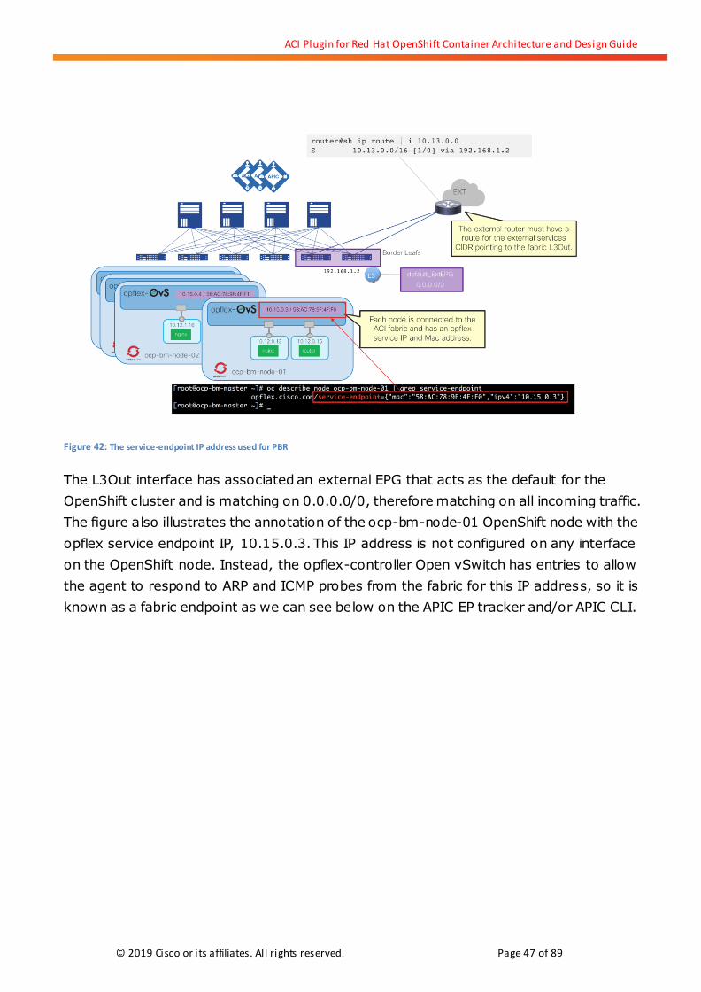
Figure 42: The service-endpoint IP address used for PBR
The L3Out interface has associated an external EPG that acts as the default for the
OpenShift cluster and is matching on 0.0.0.0/0, therefore matching on all incoming traffic.
The figure also illustrates the annotation of the ocp-bm-node-01 OpenShift node with the
opflex service endpoint IP, 10.15.0.3. This IP address is not configured on any interface
on the OpenShift node. Instead, the opflex-controller Open vSwitch has entries to allow
the agent to respond to ARP and ICMP probes from the fabric for this IP address, so it is
known as a fabric endpoint as we can see below on the APIC EP tracker and/or APIC CLI.
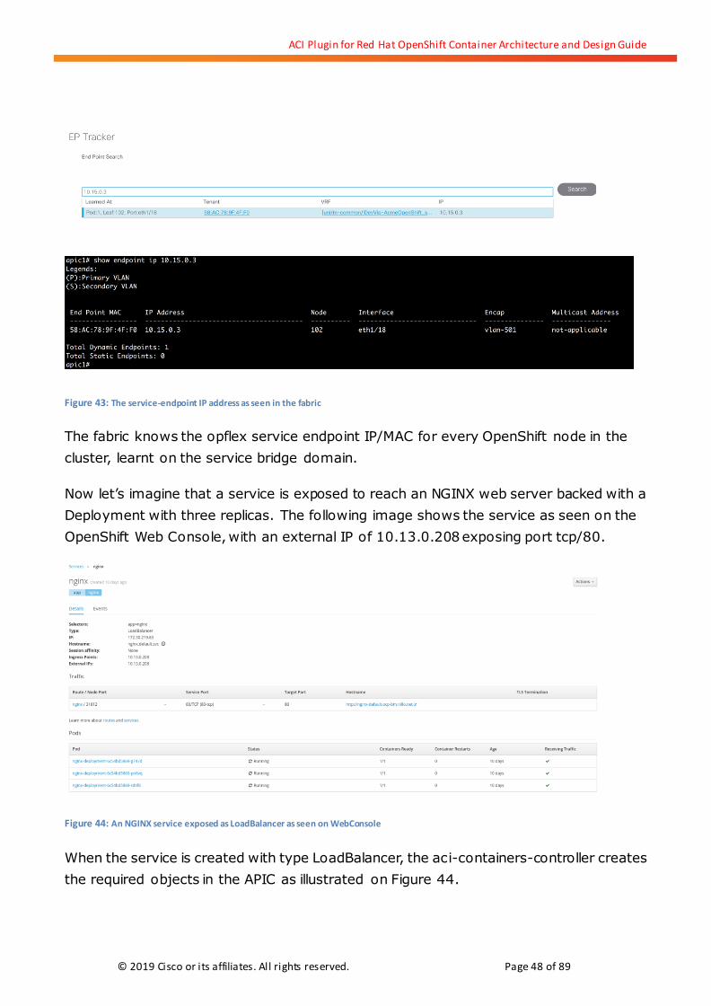
ACI Plugin for Red Hat OpenShift Container Architecture and Design Guide
© 2019 Cisco or its affiliates. All rights reserved. Page 48 of 89
Figure 43: The service-endpoint IP address as seen in the fabric
The fabric knows the opflex service endpoint IP/MAC for every OpenShift node in the
cluster, learnt on the service bridge domain.
Now let’s imagine that a service is exposed to reach an NGINX web server backed with a
Deployment with three replicas. The following image shows the service as seen on the
OpenShift Web Console, with an external IP of 10.13.0.208 exposing port tcp/80.
Figure 44: An NGINX service exposed as LoadBalancer as seen on WebConsole
When the service is created with type LoadBalancer, the aci-containers-controller creates
the required objects in the APIC as illustrated on Figure 44.
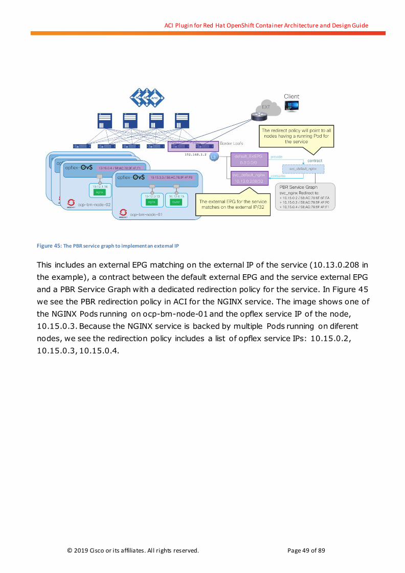
ACI Plugin for Red Hat OpenShift Container Architecture and Design Guide
© 2019 Cisco or its affiliates. All rights reserved. Page 49 of 89
Figure 45: The PBR service graph to implement an external IP
This includes an external EPG matching on the external IP of the service (10.13.0.208 in
the example), a contract between the default external EPG and the service external EPG
and a PBR Service Graph with a dedicated redirection policy for the service. In Figure 45
we see the PBR redirection policy in ACI for the NGINX service. The image shows one of
the NGINX Pods running on ocp-bm-node-01 and the opflex service IP of the node,
10.15.0.3. Because the NGINX service is backed by multiple Pods running on diferent
nodes, we see the redirection policy includes a list of opflex service IPs: 10.15.0.2,
10.15.0.3, 10.15.0.4.

ACI Plugin for Red Hat OpenShift Container Architecture and Design Guide
© 2019 Cisco or its affiliates. All rights reserved. Page 50 of 89
Figure 46: The PBR redirection policy for an external IP service
The aci-containers-controller monitors the kubernetes endpoint API to learn if there are
Pods that are added or removed to back the service object. If Pods are added on new
OpenShift nodes, the PBR redirection policy is updated to include those nodes’ service IP
address.
Now let’s look at the packet flow when an external client accesses the external service IP
address, 10.13.0.208. We assume the external router has a route for the extern_static
subnet3. The client sources the packet with 192.168.2.2 and sends it to its default
gateway that eventually routes it towards the L3Out.
3 This route can be dynamically advertised, see
https://www.cisco.com/c/en/us/td/docs/switches/datacenter/aci/apic/sw/kb /b_Cisco_ACI_and_OpenShift_Integration.htm
l#id_90196

ACI Plugin for Red Hat OpenShift Container Architecture and Design Guide
© 2019 Cisco or its affiliates. All rights reserved. Page 51 of 89
Figure 47: Packet walk of accessing an external IP via PBR Service Graph
As the packet reaches the L3Out on the border leaf, the source IP matches the default
external EPG classification, but the destination 10.13.0.208/32 matches the NGINX
service external EPG, and contract between the two applies.
Figure 48: Packet walk of accessing an external IP via PBR Service Graph
This contract has a PBR Service Graph attached which has three redirection endpoints
corresponding to the nodes with NGINX pods running. The 5-tuple of the packet is hashed

ACI Plugin for Red Hat OpenShift Container Architecture and Design Guide
© 2019 Cisco or its affiliates. All rights reserved. Page 52 of 89
to select one of the nodes. Subsequent packets of the same flow is redirected always to
the same node for the duration of the flow. The redirection policy helps finding out the
next-hop MAC address and the packet is sent over the service Bridge Domain to the
egress VTEP leaf connected to the OpenShift node.
Figure 49: Packet walk of accessing an external IP via PBR Service Graph
The packet reaches the Open vSwitch of the OpenShift node, where opflex has configured
entries to accept traffic to the opflex service MAC address and to NAT the external service
IP, 10.13.0.208 in the example, to the Pod’s IP address, 10.12.0.13. If more than one Pod
was running on the node for the given service, a second stage load balancing decision
would take place obviously.
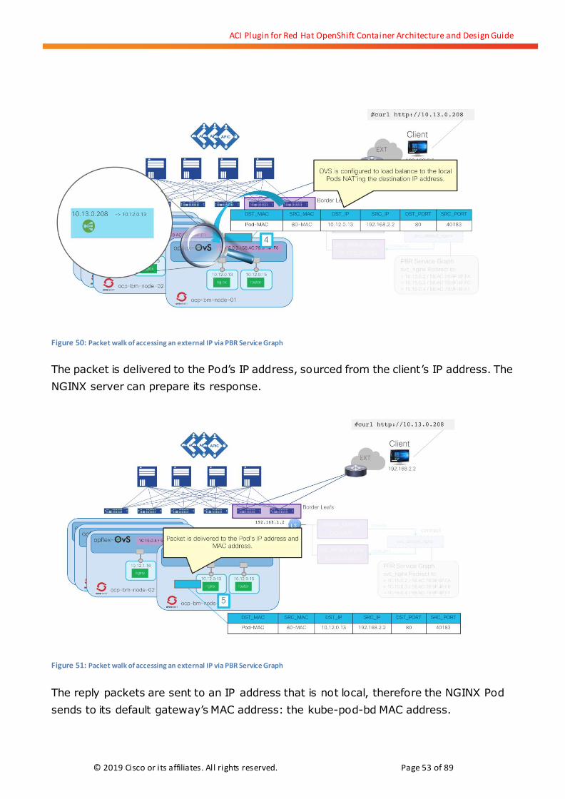
ACI Plugin for Red Hat OpenShift Container Architecture and Design Guide
© 2019 Cisco or its affiliates. All rights reserved. Page 53 of 89
Figure 50: Packet walk of accessing an external IP via PBR Service Graph
The packet is delivered to the Pod’s IP address, sourced from the client’s IP address. The
NGINX server can prepare its response.
Figure 51: Packet walk of accessing an external IP via PBR Service Graph
The reply packets are sent to an IP address that is not local, therefore the NGINX Pod
sends to its default gateway’s MAC address: the kube-pod-bd MAC address.
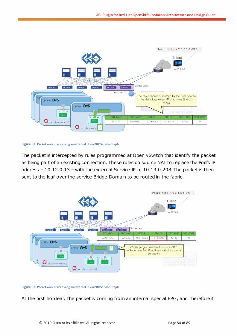
ACI Plugin for Red Hat OpenShift Container Architecture and Design Guide
© 2019 Cisco or its affiliates. All rights reserved. Page 54 of 89
Figure 52: Packet walk of accessing an external IP via PBR Service Graph
The packet is intercepted by rules programmed at Open vSwitch that identify the packet
as being part of an existing connection. These rules do source NAT to replace the Pod’s IP
address – 10.12.0.13 – with the external Service IP of 10.13.0.208. The packet is then
sent to the leaf over the service Bridge Domain to be routed in the fabric.
Figure 53: Packet walk of accessing an external IP via PBR Service Graph
At the first hop leaf, the packet is coming from an internal special EPG, and therefore it

ACI Plugin for Red Hat OpenShift Container Architecture and Design Guide
© 2019 Cisco or its affiliates. All rights reserved. Page 55 of 89
does not match the PBR redirection which is only between the two external EPGs of the
L3Out. The destination IP address however matches the default external EPG and the
packet is routed to the border leaf.
Figure 54: Packet walk of accessing an external IP via PBR Service Graph
Finally, the packet is routed at the Border Leaf towards the external router and eventually
to the originating client. The client receives the packet sources from the external service
IP, and not from the Pod IP.
5.4.6. Distributed Firewall for Network Policies
OpenShift can leverage Kubernetes NetworkPolicy objects to define a micro segmentation
security model for applications. This capability was introduced to OpenShift 3.5 as Tech
Preview and was made Generally Available (GA) in 3.7 with supported CNI plugins.
NetworkPolicy objects define a white-list security model. In other words: all traffic is
denied except traffic explicitly allowed by the policy. Policies are applied to Pods by
matching on a number of selector fields. The selector can match on items such has
namespace and Pod labels. These policies can be owned by developers, OpenShift
administrators, network or security administrators. Given the declarative nature of
NetworkPolicies, they can be added to the OpenShift applications as part of their lifecycle.

ACI Plugin for Red Hat OpenShift Container Architecture and Design Guide
© 2019 Cisco or its affiliates. All rights reserved. Page 56 of 89
The Cisco ACI CNI plugin supports NetworkPolicy objects. Cisco ACI’s native policy model
revolves around establishing contracts that define the connectivity allowed between
groups of endpoints (EPGs). However, native NetworkPolicy is not made of contracts
between EPGs. Therefore, it is represented using another policy object in APIC called Host
Protection Profiles (HPP; hostprot:Pol object class in APIC object model).
Host Protection Profiles enable APIC to represent security models such as Neutron
Security Groups and Kubernetes NetworkPolicies. The HPP is implemented with a
tenant-level object called hostprot:Pol and enables composable policies to be applied
to a Virtual Machine or container virtual Ethernet interface by forming relationships with
their corresponding opflex:IDEp endpoint objects.
HPP are communicated to the Opflex Agent on the OpenShift nodes where there are Pods
that require them to implement NetworkPolicy. The Opflex Agent in turn creates Openflow
rules on Open vSwitch to implement stateful firewall rules that enforce the required
configuration.
Figure 55
To illustrate how this works we will look at a basic example above these lines where we
can see a network policy named ‘allow-redis-frontend’. This network policy applies ingress
filters to Pods that match the labels “app: redis” and “tier: backend”. The filters are
configured to allow traffic to the selected Pods from others matching the labels “app:
guestbook” and “tier: frontend”, only permitting connectivity to tcp/6379.
That network policy is translated by APIC into a tenant-level Host Protection Policy profile

ACI Plugin for Red Hat OpenShift Container Architecture and Design Guide
© 2019 Cisco or its affiliates. All rights reserved. Page 57 of 89
like so (we are showing JSON notation just for better readability):
Figure 56
The Host Protection policies created to implement OpenShift NetworkPolicy objects can
also be seen on the APIC GUI, as shown in Figure 56. We see the YAML text description of
the network policy and the object created on APIC that corresponds to the JSON object
shown above.

ACI Plugin for Red Hat OpenShift Container Architecture and Design Guide
© 2019 Cisco or its affiliates. All rights reserved. Page 58 of 89
Figure 57: A NetworkPolicy object and corresponding Host Protection Policy
On Figure 57 we can also see a list of IP addresses that in this example correspond to
frontend Pods that are allowed to communicate with the ‘redis’ backend as per the
configured NetworkPolicy.

ACI Plugin for Red Hat OpenShift Container Architecture and Design Guide
© 2019 Cisco or its affiliates. All rights reserved. Page 59 of 89
Figure 58: A NetworkPolicy object and corresponding Host Protection Policy
Effectively this means that you can have many Pods on the same EPG, for instance on the
kube-default EPG, and microsegment all traffic between them using a stateful firewall
programmed on Open vSwitch by the opflex agent.
We can see this illustrated in Figure 58 where multiple frontend Pods, a redis Pod and a
busybox Pod running on two different nodes and all connected to the same kube-default
EPG. We illustrate the firewall rules that are programmed by the opflex agent as required
to implement NetworkPolicy.

ACI Plugin for Red Hat OpenShift Container Architecture and Design Guide
© 2019 Cisco or its affiliates. All rights reserved. Page 60 of 89
Figure 59: Using NetworkPolicy objects to implement a distributed firewall for Pods
We have already seen the NetworkPolicy allow-redis-frontend described earlier and how it
is seen in APIC (see Figure 56). In Figure 59 we can see a view of the OpenFlow rules
programmed for the selected Pod redis (redis-master specifically).
Figure 60: Host Protection Policy implemented as OVS OpenFlow rules
Those rules allow TCP/6379 only to the redis-master and only from the frontend Pod IP
addresses. This means that despite being on the same EPG and on the same node, traffic

ACI Plugin for Red Hat OpenShift Container Architecture and Design Guide
© 2019 Cisco or its affiliates. All rights reserved. Page 61 of 89
from the local frontend Pod is allowed only to tcp/6379 and no traffic at all is allowed from
the busybox Pod since it does not match any policy, as we illustrate on Figure 60.
Figure 61: Host Protection Policy are enforced locally and between nodes
The OpenShift administrator, security administrator, etc. can apply the NetworkPolicy by
applying the YAML file described earlier directly on the CLI or by using the Web Console as
seen below.
Figure 62: NetworkPolicy objects as seen on the Web Console
Also, from the web console it is possible to see for every Pod which policies are applied by

ACI Plugin for Red Hat OpenShift Container Architecture and Design Guide
© 2019 Cisco or its affiliates. All rights reserved. Page 62 of 89
looking at the Pod annotations, where we see all required policies implemented by the
Cisco ACI CNI plugin. We show the same example for the redis-master Pod in Figure 62.
Figure 63: Pod details showing ACI annotations
Once again, the goal of the ACI CNI plugin is to provide network and security capabilities
as well as facilitate operations. Both OpenShift and APIC operators can see the configured
network policies.
NetworkPolicy can be used to provide segmentation at various levels. You can use it to
isolate different namespaces, or tiers of an application. It is outside of the scope of this
document to describe how to best use NetworkPolicy objects, however one important
consideration is that if you define NetworkPolicy to isolate namespaces, you must always
remember to allow connectivity back to the default namespace in order for applications to
be exposed via the OpenShift routers. EPG-based segmentation might prove to be a
simpler option if you’re not intimately familiar with NetworkPolicy objects.

ACI Plugin for Red Hat OpenShift Container Architecture and Design Guide
© 2019 Cisco or its affiliates. All rights reserved. Page 63 of 89
5.4.7. EPG-level Segmentation for Kubernetes Objects Using Annotations
The previous section explained how the Cisco ACI CNI plugin implements OpenShift
Network Policies, which is the native way to implement micro segmentation in
Kubernetes.
ACI has other ways to achieve segmentation; those are not limited to Kubernetes clusters.
So far, we have seen the default and basic application profile created by the
acc-provisioning tool to deploy connectivity OpenShift clusters and the Pods running
on them. In that case, all OpenShift Pods from all namespaces are placed inside the
kube-default EPG where any to any communication is permitted by default. Using
NetworkPolicy on OpenShift, we saw how it is possible to restrict connectivity between
namespaces and/or more granularly between application tiers, as seen in the previous
section. This means NetworkPolicy can implement intra-EPG segmentation very easily.
It is also possible to connect Pods or entire namespaces to different EPGs. We have
already seen a hint of this in Figure 62, where you can see the annotations for a Pod as
seen on the OpenShift Web Console, including the information about the tenant and EPG.
You can use Kubernetes annotations to attach arbitrary metadata to objects. The
metadata in an annotation can be small or large, structure or unstructured and does not
have the character set restrictions imposed of Kubernetes labels.
The Cisco ACI CNI plugin leverages Kubernetes ‘annotations’ to indicate the EPG that a
Pod must be connected to. The annotation syntax used is as follows:
Figure 64
Essentially, you use the ‘opflex.cisco.com/endpoint-group’ annotation followed by a JSON
object that specifies the tenant, application profile and EPG names. You can annotate an
object at runtime by using the OpenShift Web Console or the ‘oc annotate’ CLI, or you can
add the annotation to the YAML definition of the object at creation time.
You can use the opflex endpoint-group annotation on three types of objects:
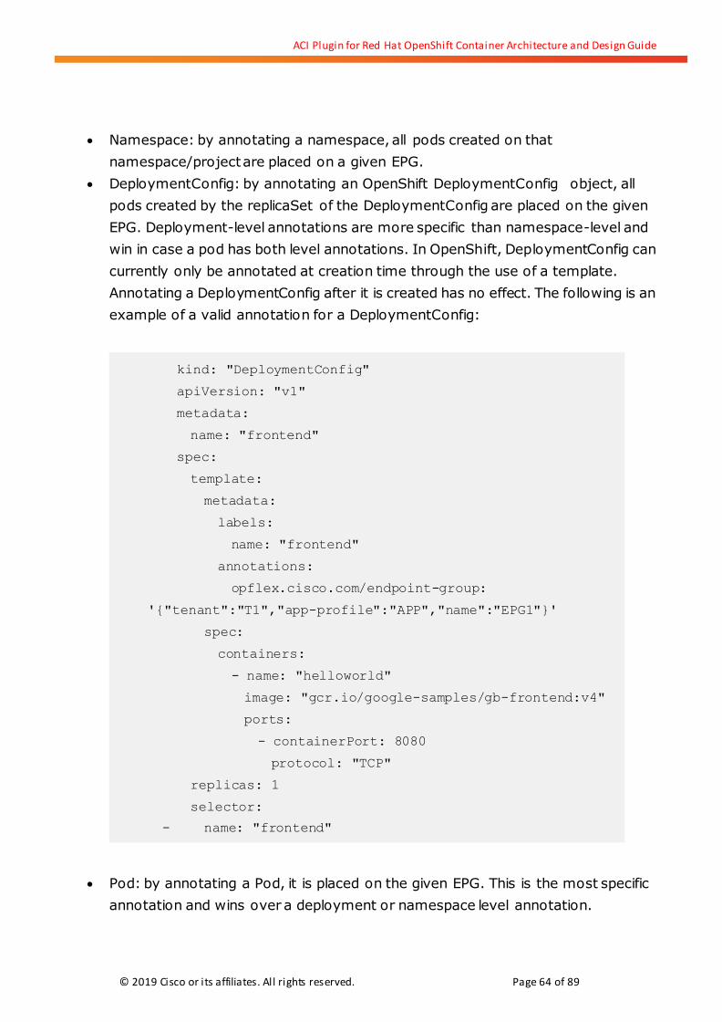
ACI Plugin for Red Hat OpenShift Container Architecture and Design Guide
© 2019 Cisco or its affiliates. All rights reserved. Page 64 of 89
Namespace: by annotating a namespace, all pods created on that
namespace/project are placed on a given EPG.
DeploymentConfig: by annotating an OpenShift DeploymentConfig object, all
pods created by the replicaSet of the DeploymentConfig are placed on the given
EPG. Deployment-level annotations are more specific than namespace-level and
win in case a pod has both level annotations. In OpenShift, DeploymentConfig can
currently only be annotated at creation time through the use of a template.
Annotating a DeploymentConfig after it is created has no effect. The following is an
example of a valid annotation for a DeploymentConfig:
Pod: by annotating a Pod, it is placed on the given EPG. This is the most specific
annotation and wins over a deployment or namespace level annotation.
kind: "DeploymentConfig"
apiVersion: "v1"
metadata:
name: "frontend"
spec:
template:
metadata:
labels:
name: "frontend"
annotations:
opflex.cisco.com/endpoint-group:
'{"tenant":"T1","app-profile":"APP","name":"EPG1"}'
spec:
containers:
- name: "helloworld"
image: "gcr.io/google-samples/gb-frontend:v4"
ports:
- containerPort: 8080
protocol: "TCP"
replicas: 1
selector:
- name: "frontend"
ACI Plugin for Red Hat OpenShift Container Architecture and Design Guide
© 2019 Cisco or its affiliates. All rights reserved. Page 65 of 89
Whatever the object annotated, it is important to understand the following points with
respect to the selected EPG:
The Tenant, Application Profile and EPG must exist prior to using annotations that
results in Pods connecting to it. Otherwise, an error is logged by the
aci-containers-controller as it tried to connect Pods to an inexistent EPG. It is
therefore recommended to automate the creation of the EPG and contracts before
launching Pods and Services. A simple Ansible playbook can be used for that
purpose (see Annex A).
The EPG must be associated to the Bridge Domain used for Pods, that is the
kube-pod-bd created by the acc-provision tool. If this BD is created on a given
tenant, then the Application Profile and EPGs used must be on the same tenant.
The EPG must be associated with the OpenShift VMM Domain.
The EPG must provide and consume the basic contracts used by the kube-default
EPG on the Kubernetes application profile. At the very minimum, health-check,
icmp, dns and kube-api should be added to the EPG.
You should add a contract between the new EPG and the kube-default EPG to allow
the Pods to reach the OpenShift routers (again, this is best achieved through
automation)
Note: you can use the ACI contract inheritance feature to reduce the configuration
complexity here
As with other sections, we will look at an example to better illustrate how to use
annotations. In Figure 64 we see how we can create a new Application Profile and a new
EPG named NewEPG which is mapped to the VMM domain of the OpenShift cluster and the
kube-pod-bd.
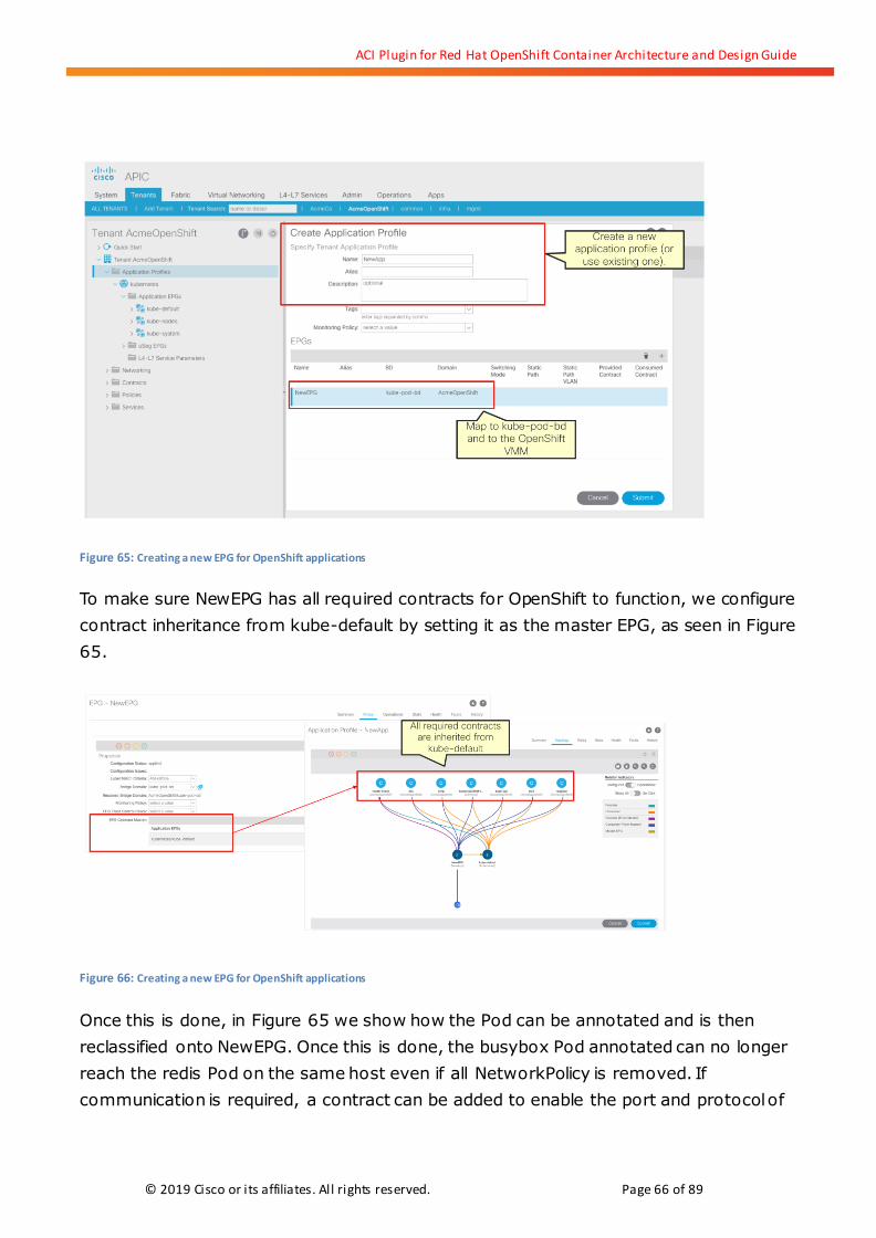
ACI Plugin for Red Hat OpenShift Container Architecture and Design Guide
© 2019 Cisco or its affiliates. All rights reserved. Page 66 of 89
Figure 65: Creating a new EPG for OpenShift applications
To make sure NewEPG has all required contracts for OpenShift to function, we configure
contract inheritance from kube-default by setting it as the master EPG, as seen in Figure
65.
Figure 66: Creating a new EPG for OpenShift applications
Once this is done, in Figure 65 we show how the Pod can be annotated and is then
reclassified onto NewEPG. Once this is done, the busybox Pod annotated can no longer
reach the redis Pod on the same host even if all NetworkPolicy is removed. If
communication is required, a contract can be added to enable the port and protocol of

ACI Plugin for Red Hat OpenShift Container Architecture and Design Guide
© 2019 Cisco or its affiliates. All rights reserved. Page 67 of 89
choice. That contract is installed and enforced on the ACI leaf and on Open vSwitch, by
means of the opflex agent.
Figure 67: Using annotations to place a Pod on an EPG
5.4.8. Opflex-OVS DataPath
The Cisco ACI CNI plugin for Red Hat OpenShift Container Platform leverages a fully
distributed data path implementation for all networking features implemented. The data
path involves both software and hardware forwarding elements, optimally combined to
ensure that no communication flow is penalized in throughput or latency.
All Pod traffic is received and processed first on Open vSwitch, which acts as kind o f open
virtual leaf of the fabric by means of the opflex agent controlling it. We have seen before
that the Cisco ACI CNI plugin creates the virtual Ethernet interface for the Pod IP network
namespace and connects it to an OVS Bridge.
The opflex OVS implementation leverages two different bridges to implement different
features: br-access and br-int. Pod virtual Ethernet interfaces are connected to the
br-access bridge. This is shown in Figure 67, where we highlight one of the NGINX Pods
from previous example as seen on the APIC GUI and the diagram that shows how it is
connected to the br-fabric. The same figure also shows, for reference, one of the Pods
implementing the ingress routers.
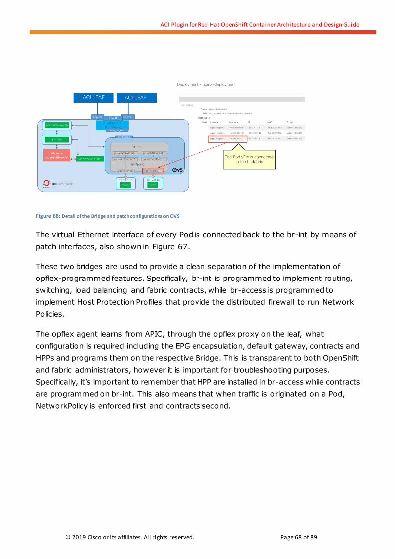
ACI Plugin for Red Hat OpenShift Container Architecture and Design Guide
© 2019 Cisco or its affiliates. All rights reserved. Page 68 of 89
Figure 68: Detail of the Bridge and patch configurations on OVS
The virtual Ethernet interface of every Pod is connected back to the br-int by means of
patch interfaces, also shown in Figure 67.
These two bridges are used to provide a clean separation of the implementation of
opflex-programmed features. Specifically, br-int is programmed to implement routing,
switching, load balancing and fabric contracts, while br-access is programmed to
implement Host Protection Profiles that provide the distributed firewall to run Network
Policies.
The opflex agent learns from APIC, through the opflex proxy on the leaf, what
configuration is required including the EPG encapsulation, default gateway, contracts and
HPPs and programs them on the respective Bridge. This is transparent to both OpenShift
and fabric administrators, however it is important for troubleshooting purposes.
Specifically, it’s important to remember that HPP are installed in br-access while contracts
are programmed on br-int. This also means that when traffic is originated on a Pod,
NetworkPolicy is enforced first and contracts second.

ACI Plugin for Red Hat OpenShift Container Architecture and Design Guide
© 2019 Cisco or its affiliates. All rights reserved. Page 69 of 89
6. Cisco ACI CNI Plugin for OpenShift Design and Use Cases
6.1. Namespace Segmentation, Application Segmentation and Security
Options
OpenShift Projects use Kubernetes namespaces to allow different users to share a single
cluster. It is a common requirement that applications running on a given namespace
should not by default be able to communicate with applications running on other
namespaces, commonly referred to as namespace isolation.
The Cisco ACI CNI plugin offers various alternatives to implement segmentation for
OpenShift applications. This includes making use of Network Policy objects to provide
namespace or application-tier segmentation as well as using EPGs for segmentation.
6.2. Using EPGs for Cluster Level Isolation
The default installation mode of the ACI CNI plugin implements cluster-level isolation by
placing all Pods from a given cluster in the kube-default EPG on the ACI fabric tenant
provided for the cluster at installation time. This means that user Pods are by default
isolated from Pods from other clusters as well as from infrastructure components since
Pods can only access the node IP addresses (on kube-node EPG) by means of the
specifically configured contracts. Workloads on the kube-default EPG can communicate
with other fabric endpoints by defining additional contracts.
The OpenShift router also runs on the kube-default EPG and is exposed externally by the
LoadBalancer service implemented using ACI Policy Based Redirection.
Within the kube-default EPG there are no restrictions for communication between Pods.
However, if more granular segmentation is required between the Pods running within
kube-default EPG, it is possible to define OpenShift Network Policy objects that is
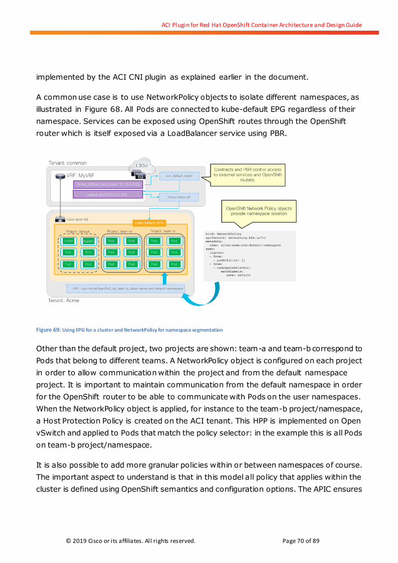
ACI Plugin for Red Hat OpenShift Container Architecture and Design Guide
© 2019 Cisco or its affiliates. All rights reserved. Page 70 of 89
implemented by the ACI CNI plugin as explained earlier in the document.
A common use case is to use NetworkPolicy objects to isolate different namespaces, as
illustrated in Figure 68. All Pods are connected to kube-default EPG regardless of their
namespace. Services can be exposed using OpenShift routes through the OpenShift
router which is itself exposed via a LoadBalancer service using PBR.
Figure 69: Using EPG for a cluster and NetworkPolicy for namespace segmentation
Other than the default project, two projects are shown: team-a and team-b correspond to
Pods that belong to different teams. A NetworkPolicy object is configured on each project
in order to allow communication within the project and from the default namespace
project. It is important to maintain communication from the default namespace in order
for the OpenShift router to be able to communicate with Pods on the user namespaces.
When the NetworkPolicy object is applied, for instance to the team-b project/namespace,
a Host Protection Policy is created on the ACI tenant. This HPP is implemented on Open
vSwitch and applied to Pods that match the policy selector: in the example this is all Pods
on team-b project/namespace.
It is also possible to add more granular policies within or between namespaces of course.
The important aspect to understand is that in this model all policy that applies within the
cluster is defined using OpenShift semantics and configuration options. The APIC ensures

ACI Plugin for Red Hat OpenShift Container Architecture and Design Guide
© 2019 Cisco or its affiliates. All rights reserved. Page 71 of 89
the policies are implemented with a stateful distributed firewall and offers the fabric
administrator visibility of the configured policies.
6.3. Using EPGs for Project Level Isolation
Using OpenShift Network Policy objects, it is possible to provide extremely granular levels
of isolation, but these depend always exclusively on the configurations of the OpenShift
administrators. For security and compliance purposes, it may be desirable to ensure that
different projects are isolated from one another and that communication between them
cannot be achieved directly without having privileges beyond the OpenShift cluster. Using
the ACI CNI plugin it is very easy to achieve this objective by leveraging the native
segmentation and security capabilities of the fabric.
To achieve project-level isolation, you must be creating a new EPG for every new
OpenShift Project. In Figure 69, we show a possible design with an Application Profile for
OpenShift Projects and two EPGs for two different OpenShift projects, one for Team-A and
another for Team-B.
Figure 70: Using EPGs for OpenShift project segmentation

ACI Plugin for Red Hat OpenShift Container Architecture and Design Guide
© 2019 Cisco or its affiliates. All rights reserved. Page 72 of 89
At the time creation, the OpenShift project must be annotated to use the right EPG. This
can be done in a number of ways, for instance using the ‘oc’ CLI as shown below:
Figure 71
Once this is done, all Pods created within each project are on a dedicated EPG and are only
able to communicate with other projects if an ACI admin establishes ACI contracts to do
so. As shown in Figure 71, the EPGs for each project need to have associations to the
contracts that allow OpenShift to function and the easiest way to ensure that is to
configure them to inherit contracts from kube-default. An additional contract must be
created between the kube-default EPG and the new EPGs to allow connectivity between
the OpenShift router and the project/namespace Pods.
When using this model, it is important to plan for the event when a project is not
annotated, because in that case its Pods are placed on the kube-default EPG. Since the
OpenShift router is on the Default project and is running on kube-default EPG, those
non-annotated projects are able to expose routes through the OpenShift router. For this
reason, it is a good idea to define an EPG dedicated for the Default OpenShift project and
to annotate that project to be outside of the kube-default EPG. In this manner, the
OpenShift router is no longer on kube-default EPG and if a project is defined without the
right annotations, its Pods are completely isolated.

ACI Plugin for Red Hat OpenShift Container Architecture and Design Guide
© 2019 Cisco or its affiliates. All rights reserved. Page 73 of 89
Figure 72: Using EPGs for OpenShift project segmentation
If communication is required between projects, contracts must be defined to allow for this
communication to happen. Of course, within a given project’s EPG, it is still possible to use
NetworkPolicy to define more granular segmentation down to the application tier.
6.4. Using EPGs for Application Tier Isolation
It also possible to define EPGs for specific application tiers within a given project by using
the annotations model. Again, in this case a prevision must be taken for the eventuality
that a non-annotated Pod could end in the wrong EPG. Just like explained before, it is best
to create an EPG for the ‘default’ namespace so that the OpenShift routers are placed
there, thus leaving kube-default as a catch-all for non-annotated Pods to be isolated.
Then an application profile can be defined for each OpenShift project and within the
application profile, an EPG for each Deployment Config.
This model is depicted in Figure 72. In that picture the default namespace is still on
kube-default EPG, but we show a two-tier application with a frontend tier and a Redis
database tier each having its own EPG. The Pod templates used to build each tier must be
annotated to the right EPG. This allows for granular contract usage so that communication
between tiers is whitelisted with contracts and also only the tier that requires to expose
routes has access to the OpenShift routers.

ACI Plugin for Red Hat OpenShift Container Architecture and Design Guide
© 2019 Cisco or its affiliates. All rights reserved. Page 74 of 89
Figure 73: Using EPGs for OpenShift application segmentation
As in previous examples, the use of EPG and contracts for segmentation does not prevent
complementing it with the use of NetworkPolicy objects, but it does mean that the policy
can be controlled completely by administrators outside of the OpenShift cluster if that is
required.
6.5. Enhancing the Kubernetes Application Profile for OpenShift
The default Kubernetes application considers only the basic contracts to let a cluster
function. Red Hat OpenShift Container Platform allows administrators to install many
additional functions, some of which run on its own dedicated namespaces.
For example, OpenShift can use Hawkular and Heapster to collect metrics. These services
are deployed on the Project OpenShift-infra. Another example is the OpenShift Web
Console, which is deployed to OpenShift-web-console project.
It is a good practice to define EPGs for each of these infrastructure namespaces and
annotate the namespace/project in order to place all Pods in their respective EPGs. This
can be convenient for various reasons. First, to ensure that user Pods cannot directly
access these infrastructure Pods. Second, by having infrastructure Pods in dedicated EPGs,
the fabric admin can have better visibility in APIC for these services.
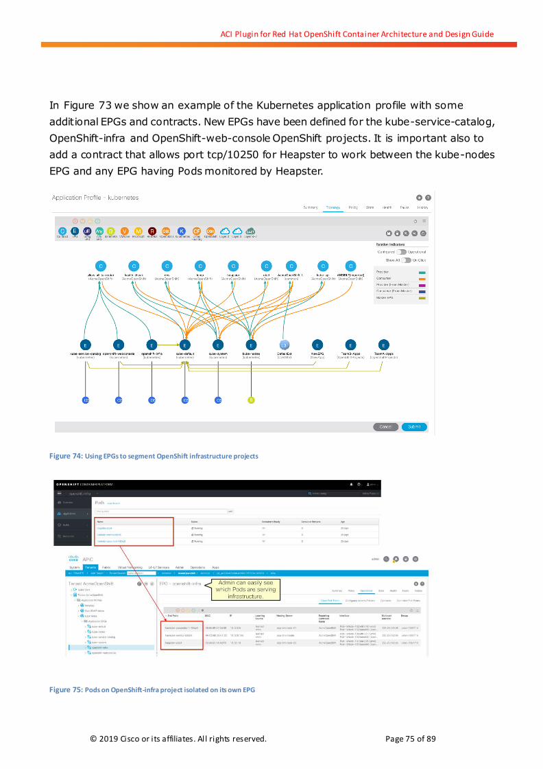
ACI Plugin for Red Hat OpenShift Container Architecture and Design Guide
© 2019 Cisco or its affiliates. All rights reserved. Page 75 of 89
In Figure 73 we show an example of the Kubernetes application profile with some
additional EPGs and contracts. New EPGs have been defined for the kube-service-catalog,
OpenShift-infra and OpenShift-web-console OpenShift projects. It is important also to
add a contract that allows port tcp/10250 for Heapster to work between the kube-nodes
EPG and any EPG having Pods monitored by Heapster.
Figure 74: Using EPGs to segment OpenShift infrastructure projects
Figure 75: Pods on OpenShift-infra project isolated on its own EPG

ACI Plugin for Red Hat OpenShift Container Architecture and Design Guide
© 2019 Cisco or its affiliates. All rights reserved. Page 76 of 89
6.6. Eliminate the need for Egress Routers
A common problem of using network overlays is that gateways are required to allow
connectivity between endpoints in the overlay and endpoints outside of the overlay. For
exposing services to external endpoints, we have seen in the previous section that the
OpenShift router can provide an entry gateway.
However, a gateway is traditionally required also for egress traffic. We define “egress
traffic” here not as traffic that is sent out of the cluster as a response to a connection from
external endpoints, but as Pod traffic that initiates a connection to external endpoints.
When using the native OpenShift SDN options, an egress router function is provided. This
works by essentially designating a node to act as the egress gateway and NAT all traffic
out of the cluster. This solution presents three challenges:
1. It funnels all egress traffic through one node, adding latency and introducing a
performance bottleneck.
2. If the node selected fails, traffic is black holed until a new node can be made
available.
3. Traffic must be NAT’ed outside of the overlay. This means that all traffic from a
namespace (or even from a cluster) is seen as one IP Address.
While there’s been enhancements since OpenShift 3.10 in terms of availability, such as
“HA namespace-wide egress IP” or automatic namespace-wide egress IP, use of egress
routers represents a challenge for applications requiring high-speed, low-latency access
from the cluster to external endpoints.
When using the Cisco ACI CNI plugin, OpenShift Pods connect to the same integrated
overlay as any other workloads. This means that there is no need to have gateways to
establish connectivity between any OpenShift Pod and any other fabric endpoint, be it a
Virtual Machine, a Bare Metal server or another Pod from another cluster. This has the
following advantages compared to using egress routers:
1. Traffic is routed from every node via the optimal path to the destination,
offering lowest possible latency and highest throughput. There are no
bottlenecks.

ACI Plugin for Red Hat OpenShift Container Architecture and Design Guide
© 2019 Cisco or its affiliates. All rights reserved. Page 77 of 89
2. Because no gateways are required, the solution is inherent highly available.
3. By leveraging EPG annotations down to the application tier level it is easy to
have very granular control about which Pods can access which external services
without requiring NAT.
When using the Cisco ACI CNI plugin every Pod is connected to the fabric’s integrated
VXLAN overlay as much as every other endpoint. This means that the fabric can route
traffic between any Pod and any other fabric endpoint. Using EPGs and contracts it is
possible to restrict connectivity very granularly. In Figure 75, we show a configuration
where an OpenShift cluster is using subnet 10.12.0.1/16 for Pod IP addresses configured
on kube-pod-bd. We also show another BD, called legacy-bd with subnet 172.16.1.1/24.
The fabric knows how to route between the two Bridge Domains. A fabric or security
administrator, or an automation system with the equivalent responsibilities can configure
a contract to allow connectivity between an EPG mapped to the OpenShift VMM domain
and an EPG mapped to any other domain, in the example a Physical Domain for Bare
Metal.
Figure 76: A template is annotated to place Pods from a Deployment Config on NewEPG
The OpenShift administrator or developer can edit the Deployment Config YAML, as seen
in the figure, to ensure that all Pods of the ‘newapp’ are connected to the EPG that has
access to the baremetal database.
The ACI CNI plugin connects all Pods that are part of the Deployment Config to the right
EPG. In addition, the opflex agent also programs the ACI contracts on Open vSwitch, just

ACI Plugin for Red Hat OpenShift Container Architecture and Design Guide
© 2019 Cisco or its affiliates. All rights reserved. Page 78 of 89
like it does for Network Policy. Therefore, as seen in Figure 76 all Pods on the ‘newapp’
EPG have access to the database. Pods in other EPGs, such as kube-default, do not have
access.
Figure 77: Pods part of newapp deployment config can access the DB because of the configured contract
As seen on the illustration, traffic from each of the OpenShift nodes is routed to the
destination database directly if allowed by the contract. There is no need to send the
traffic to an egress router, nor is there a need to NAT it because all endpoints are known
to the ACI fabric.
It is also possible to combine this model with ACI Service Graphs in order to have the
traffic between the OpenShift cluster and EPGs mapped to Bare Metal, VMware, Microsoft
or Red Hat Virtualization VMM domains be filtered by a Next Generation Firewall.
6.7. L3Out Options
L3Out interfaces specify how an ACI fabric connects with external routed networks. An
L3Out interface can span multiple leaf switches and can use both static and dynamic
routing protocols to advertise the fabric’s local subnets and to learn external ones.
Apart from learning how to route to external prefixes, L3Out interfaces have associated “Network”
objects (InstP in the object model) which are referred to as External EPGs. Similar to regular EPGs,
they specify a group of endpoints that require the same policy for communication. In the case of
External EPGs, the endpoints are specified by defining them via CIDRs.
ACI Plugin for Red Hat OpenShift Container Architecture and Design Guide
© 2019 Cisco or its affiliates. All rights reserved. Page 79 of 89
Every OpenShift cluster using the ACI CNI plugin requires access to an L3Out interface for
at least two purposes:
1. It is expected that the OpenShift nodes require access to external repositories
and/or registries that are not connected to the fabric.
2. Services exposed outside of the cluster are modelled in ACI as external EPGs
associated to the L3Out.
6.8. Single VRF, L3Out, and Multiple Clusters
A single VRF can be shared by many OpenShift clusters if it is placed in the common
tenant in ACI. It is possible to use a single L3Out in the common tenant to provide
connectivity to all the clusters external services as well as node and pod IP addresses.
No special configuration is required on the Cisco ACI CNI side.
Each OpenShift cluster can use a dedicated L3Out and VRF, configured on the tenant
where the OpenShift cluster’s Kubernetes application is defined.
6.9. Multiple OpenShift VRFs and Tenants with Shared Common L3Out
Note: This configuration is supported as of Cisco ACI CNI release 4.0(2.20181221).
Each OpenShift cluster is deployed in a dedicated tenant with its own VRF. It is possible to use a
single L3Out in the common tenant to provide external connectivity to all the OpenShift tenants.
The common L3Out uses a dedicated VRF, and the Cisco ACI fabric performs route leaking as
required.
In order for this configuration to work the following configurations must be applied:
When you create external services on OpenShift, annotate them with the
annotation: “opflex.cisco.com/ext_service_contract_scope=Global”. This
annotation instructs the Cisco ACI CNI plug-in to configure the contract scope to
global to ensure the Service Graph will allow inter-VRF traffic.
Mark the pod and node subnets under the bridge domain with the “shared between
VRFs” flag to allow that the routes are leaked.

ACI Plugin for Red Hat OpenShift Container Architecture and Design Guide
© 2019 Cisco or its affiliates. All rights reserved. Page 80 of 89
The following figure shows an example of logical configuration:
Figure 77: Logical configuration of Multiple OpenShift VRFs and with Shared Common L3Out
7. Exploring the ‘Nested-Inside’ Deployment Option
7.1. Introducing the nested-inside acc-provision parameter
It is possible to run OpenShift nodes (controllers and compute nodes) as virtual machines
hosted on a VMware vSphere cluster. This becomes particularly interesting when
networking for that vSphere cluster is managed by APIC through a VMware VMM domain.
Covering how to integrate ACI and VMware is outside the scope of this document; we
assume the reader is familiar with how to achieve this configuration. If not, refer to
https://www.cisco.com/c/en/us/td/docs/switches/datacenter/aci/apic/sw/3-x/virtualization/b_ACI
_Virtualization_Guide_3_0_1/b_ACI_Virtualization_Guide_3_0_1_chapter_011.html for more
details. Be aware that acc-provision does not create the VMware VMM on your behalf; it
needs to pre-exist before running acc-provision, exactly like the L3Out configuration.
Assuming you have a VMware VMM domain on APIC, you can connect OpenShift virtual
L3OutTenant: common
VRF: shared
kube- pod- bd
Tenant: Acme
router registry
Pod Pod
Pod Pod
default_ExtEPG 0.0.0.0/0
Acme_default_svc_router: 10.13.0.9/32
Wile- svc_default_router
Wile- l3oout- allow- all
Contracts and PBR control
access to external services
and OpenShift routers.
VRF: Acme
kube-default-EPG
Acme- svc_default_router
Acme- l3oout- allow- all
kube- pod- bd
router registry
Pod Pod
Pod Pod
VRF: Wile
kube-default-EPG
Tenant: Wile
Wile_default_svc_router: 10.14.0.9/32
Route Leaking Route Leaking

ACI Plugin for Red Hat OpenShift Container Architecture and Design Guide
© 2019 Cisco or its affiliates. All rights reserved. Page 81 of 89
nodes to a DVS managed by APIC. The acc-provision utility provides a configuration
setting that lets APIC create VLAN trunking port-groups on the DVS with the appropriate
VLANs extended for your OpenShift with ACI environment. You need to provide two
parameters to acc-provision:
1. The type and name of the VMware VMM domain your OpenShift virtualized nodes
reside. For type, use ‘vmware’.
2. The AEP that is used by your vSphere hosts to gain fabric connectivity.
This is shown below:
Figure 78
After you have configured these parameters, run acc-provision just like you normally
would. This time though, you see a new port-group on the DVS managed by APIC:

ACI Plugin for Red Hat OpenShift Container Architecture and Design Guide
© 2019 Cisco or its affiliates. All rights reserved. Page 82 of 89
Figure 79
That port-group is named after your system_id. In the picture above, a small discrepancy
exist between openshiftpeg2 and openshift-peg2, ignore it – hyphens are no longer
accepted for system_id in recent versions of acc-provision. The port-group is of the
trunking type and carries three VLANs:
1. ACI infra VLAN
2. VLAN for your OpenShift/K8s nodes (maps to the node-BD and EPG)
3. Service VLAN (for PBR services as explained above)
All you have to do now is attach the virtual NICs of your OpenShift virtualized nodes to
that port-group and configure the OpenShift virtualized nodes as if they were bare-metal
nodes. Create the appropriate VLAN interfaces on your nodes and assign IP addresses to
them. Verify your nodes can ping the node BD and you’re on your way! One caveat worth
mentioning with nested-inside is that you can’t vMotion the virtual OpenShift nodes;
doing so results in loss of connectivity.
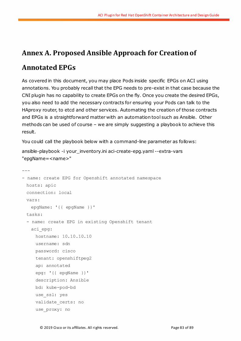
ACI Plugin for Red Hat OpenShift Container Architecture and Design Guide
© 2019 Cisco or its affiliates. All rights reserved. Page 83 of 89
Annex A. Proposed Ansible Approach for Creation of
Annotated EPGs
As covered in this document, you may place Pods inside specific EPGs on ACI using
annotations. You probably recall that the EPG needs to pre-exist in that case because the
CNI plugin has no capability to create EPGs on the fly. Once you create the desired EPGs,
you also need to add the necessary contracts for ensuring your Pods can talk to the
HAproxy router, to etcd and other services. Automating the creation of those contracts
and EPGs is a straightforward matter with an automation tool such as Ansible. Other
methods can be used of course – we are simply suggesting a playbook to achieve this
result.
You could call the playbook below with a command-line parameter as follows:
ansible-playbook -i your_inventory.ini aci-create-epg.yaml --extra-vars
"epgName=<name>"
---
- name: create EPG for Openshift annotated namespace
hosts: apic
connection: local
vars:
epgName: '{{ epgName }}'
tasks:
- name: create EPG in existing Openshift tenant
aci_epg:
hostname: 10.10.10.10
username: sdn
password: cisco
tenant: openshiftpeg2
ap: annotated
epg: '{{ epgName }}'
description: Ansible
bd: kube-pod-bd
use_ssl: yes
validate_certs: no
use_proxy: no

ACI Plugin for Red Hat OpenShift Container Architecture and Design Guide
© 2019 Cisco or its affiliates. All rights reserved. Page 84 of 89
- name: Add a new contract to EPG binding
aci_epg_to_contract:
host: 10.10.10.10
username: sdn
password: cisco
tenant: openshiftpeg2
ap: annotated
epg: '{{ epgName }}'
contract: '{{ item.name }}'
contract_type: '{{ item.status }}'
state: present
use_ssl: yes
validate_certs: no
with_items:
- { name: 'etcd', status: 'consumer' }
- { name: 'dns', status: 'consumer' }
- { name: 'icmp', status: 'consumer' }
- { name: 'default', status: 'consumer' }
- { name: 'openshiftpeg2-l3out-allow-all', status: 'consumer' }
- { name: 'kube-api', status: 'consumer' }
- { name: 'health-check', status: 'provider' }
- name: Bind EPGs to Domains on Cisco ACI fabrics (fv:RsDomAtt)
aci_epg_to_domain:
ap: annotated
domain: openshiftpeg2
domain_type: vmm
epg: '{{ epgName }}'
hostname: 10.10.10.10
password: cisco
state: present
tenant: openshiftpeg2
use_proxy: no
use_ssl: yes
username: sdn
validate_certs:
vm_provider: openshift

ACI Plugin for Red Hat OpenShift Container Architecture and Design Guide
© 2019 Cisco or its affiliates. All rights reserved. Page 85 of 89
When the playbook has executed, create a new namespace and annotate it as shown
below:
oc annotate namespace <name>
opflex.cisco.com/endpoint-group='{"tenant":"openshiftpeg2","app-profile":"annotated"
,"name":"'<name>'"}'
Pods created in that namespace automatically appear under the annotated/<name> EPG
now.