Cisco 8300 Series AON Appliance Hardware Installation ... · iii Cisco 8300 Series AON Appliance...
43
Corporate Headquarters Cisco Systems, Inc. 170 West Tasman Drive San Jose, CA 95134-1706 USA http://www.cisco.com Tel: 408 526-4000 800 553-NETS (6387) Fax: 408 526-4100 Cisco 8300 Series AON Appliance Hardware Installation Guide Text Part Number: 78-17242-01
Transcript of Cisco 8300 Series AON Appliance Hardware Installation ... · iii Cisco 8300 Series AON Appliance...

Cisco 8300 Series AON Appliance Hardware Installation Guide
Corporate HeadquartersCisco Systems, Inc.170 West Tasman DriveSan Jose, CA 95134-1706 USAhttp://www.cisco.comTel: 408 526-4000
800 553-NETS (6387)Fax: 408 526-4100
Text Part Number: 78-17242-01

THE SPECIFICATIONS AND INFORMATION REGARDING THE PRODUCTS IN THIS MANUAL ARE SUBJECT TO CHANGE WITHOUT NOTICE. ALL STATEMENTS, INFORMATION, AND RECOMMENDATIONS IN THIS MANUAL ARE BELIEVED TO BE ACCURATE BUT ARE PRESENTED WITHOUT WARRANTY OF ANY KIND, EXPRESS OR IMPLIED. USERS MUST TAKE FULL RESPONSIBILITY FOR THEIR APPLICATION OF ANY PRODUCTS.
THE SOFTWARE LICENSE AND LIMITED WARRANTY FOR THE ACCOMPANYING PRODUCT ARE SET FORTH IN THE INFORMATION PACKET THAT SHIPPED WITH THE PRODUCT AND ARE INCORPORATED HEREIN BY THIS REFERENCE. IF YOU ARE UNABLE TO LOCATE THE SOFTWARE LICENSE OR LIMITED WARRANTY, CONTACT YOUR CISCO REPRESENTATIVE FOR A COPY.
The following information is for FCC compliance of Class A devices: This equipment has been tested and found to comply with the limits for a Class A digital device, pursuant to part 15 of the FCC rules. These limits are designed to provide reasonable protection against harmful interference when the equipment is operated in a commercial environment. This equipment generates, uses, and can radiate radio-frequency energy and, if not installed and used in accordance with the instruction manual, may cause harmful interference to radio communications. Operation of this equipment in a residential area is likely to cause harmful interference, in which case users will be required to correct the interference at their own expense.
The following information is for FCC compliance of Class B devices: The equipment described in this manual generates and may radiate radio-frequency energy. If it is not installed in accordance with Cisco’s installation instructions, it may cause interference with radio and television reception. This equipment has been tested and found to comply with the limits for a Class B digital device in accordance with the specifications in part 15 of the FCC rules. These specifications are designed to provide reasonable protection against such interference in a residential installation. However, there is no guarantee that interference will not occur in a particular installation.
Modifying the equipment without Cisco’s written authorization may result in the equipment no longer complying with FCC requirements for Class A or Class B digital devices. In that event, your right to use the equipment may be limited by FCC regulations, and you may be required to correct any interference to radio or television communications at your own expense.
You can determine whether your equipment is causing interference by turning it off. If the interference stops, it was probably caused by the Cisco equipment or one of its peripheral devices. If the equipment causes interference to radio or television reception, try to correct the interference by using one or more of the following measures:
• Turn the television or radio antenna until the interference stops.
• Move the equipment to one side or the other of the television or radio.
• Move the equipment farther away from the television or radio.
• Plug the equipment into an outlet that is on a different circuit from the television or radio. (That is, make certain the equipment and the television or radio are on circuits controlled by different circuit breakers or fuses.)
Modifications to this product not authorized by Cisco Systems, Inc. could void the FCC approval and negate your authority to operate the product.
The Cisco implementation of TCP header compression is an adaptation of a program developed by the University of California, Berkeley (UCB) as part of UCB’s public domain version of the UNIX operating system. All rights reserved. Copyright © 1981, Regents of the University of California.
NOTWITHSTANDING ANY OTHER WARRANTY HEREIN, ALL DOCUMENT FILES AND SOFTWARE OF THESE SUPPLIERS ARE PROVIDED “AS IS” WITH ALL FAULTS. CISCO AND THE ABOVE-NAMED SUPPLIERS DISCLAIM ALL WARRANTIES, EXPRESSED OR IMPLIED, INCLUDING, WITHOUT LIMITATION, THOSE OF MERCHANTABILITY, FITNESS FOR A PARTICULAR PURPOSE AND NONINFRINGEMENT OR ARISING FROM A COURSE OF DEALING, USAGE, OR TRADE PRACTICE.
IN NO EVENT SHALL CISCO OR ITS SUPPLIERS BE LIABLE FOR ANY INDIRECT, SPECIAL, CONSEQUENTIAL, OR INCIDENTAL DAMAGES, INCLUDING, WITHOUT LIMITATION, LOST PROFITS OR LOSS OR DAMAGE TO DATA ARISING OUT OF THE USE OR INABILITY TO USE THIS MANUAL, EVEN IF CISCO OR ITS SUPPLIERS HAVE BEEN ADVISED OF THE POSSIBILITY OF SUCH DAMAGES.
Cisco 8300 Series AON Appliance Hardware Installation Guide © 2005-2006 Cisco Systems, Inc. All rights reserved.
CCSP, CCVP, the Cisco Square Bridge logo, Follow Me Browsing, and StackWise are trademarks of Cisco Systems, Inc.; Changing the Way We Work, Live, Play, and Learn, and iQuick Study are service marks of Cisco Systems, Inc.; and Access Registrar, Aironet, ASIST, BPX, Catalyst, CCDA, CCDP, CCIE, CCIP, CCNA, CCNP, Cisco, the Cisco Certified Internetwork Expert logo, Cisco IOS, Cisco Press, Cisco Systems, Cisco Systems Capital, the Cisco Systems logo, Cisco Unity, Empowering the Internet Generation, Enterprise/Solver, EtherChannel, EtherFast, EtherSwitch, Fast Step, FormShare, GigaDrive, GigaStack, HomeLink, Internet Quotient, IOS, IP/TV, iQ Expertise, the iQ logo, iQ Net Readiness Scorecard, LightStream, Linksys, MeetingPlace, MGX, the Networkers logo, Networking Academy, Network Registrar, Packet, PIX, Post-Routing, Pre-Routing, ProConnect, RateMUX, ScriptShare, SlideCast, SMARTnet, StrataView Plus, TeleRouter, The Fastest Way to Increase Your Internet Quotient, and TransPath are registered trademarks of Cisco Systems, Inc. and/or its affiliates in the United States and certain other countries.
All other trademarks mentioned in this document or Website are the property of their respective owners. The use of the word partner does not imply a partnership relationship between Cisco and any other company. (0502R)

C O N T E N T S
Preface v
Audience v
Conventions v
Safety Warnings vi
Related Documentation xi
Obtaining Documentatio and Submitting a Service Request xi
C H A P T E R 1 Preparing to Install the Appliance 1-1
Warnings 1-1
Working with Electricity 1-3
Preventing Damage from Electrostatic Discharge 1-3
Preventing EMI 1-4
Covering Empty Slots 1-4
Preparing Your Site for Installation 1-4
Environment 1-4
Choosing a Site for Installation 1-5
Grounding the System 1-5
Creating a Safe Environment 1-5
AC Power 1-5
Console Cable and Adapter 1-6
iiiCisco 8300 Series AON Appliance Hardware Installation Guide
78-17242-01

Physical Operating Specifications 1-7
C H A P T E R 2 Installing the Appliance 2-1
General Installation Guidelines 2-1
Ensuring Proper Air Flow 2-2
Stabilizing the System 2-2
Lifting the System 2-2
Installing the Appliance in a Rack 2-3
Rack-Mounting the Appliance 2-4
C H A P T E R 3 Operating the Appliance 3-1
Bringing the Appliance Online 3-1
Identifying External Components and Connectors 3-2
Connecting to AC Power 3-3
Connecting to a Network 3-3
Connecting a Serial Cable 3-4
Where to Go Next 3-4
Troubleshooting Hardware Problems 3-4
Using LEDs to Identify Problems 3-5
Replacing Hard Disk Drives 3-7
I N D E X
ivCisco 8300 Series AON Appliance Hardware Installation Guide
78-17242-01

Preface
This guide describes how to install the Cisco 8300 Series AON Appliance hardware platform.
AudienceThis guide is intended primarily for system administrators and other personnel familiar with installing equipment in a data center.
ConventionsThis guide uses basic conventions to represent text and table information.
Note Means reader take note. Notes contain helpful suggestions or references to materials not contained in the manual.
Caution Means reader be careful. You are capable of doing something that might result in equipment damage or loss of data.
vCisco 8300 Series AON Appliance Hardware Installation Guide
78-17242-01

PrefaceSafety Warnings
Safety WarningsSafety warnings appear throughout this guide in procedures that, if performed incorrectly, may harm you. A warning symbol precedes each warning statement. To see translations of the warnings that appear in this publication, see the Regulatory Compliance and Safety Information for the Cisco 8300 Series AON Appliance document that accompanied your router.
Warning IMPORTANT SAFETY INSTRUCTIONS
This warning symbol means danger. You are in a situation that could cause bodily injury. Before you work on any equipment, be aware of the hazards involved with electrical circuitry and be familiar with standard practices for preventing accidents. Use the statement number provided at the end of each warning to locate its translation in the translated safety warnings that accompanied this device. Statement 1071
SAVE THESE INSTRUCTIONS
Waarschuwing BELANGRIJKE VEILIGHEIDSINSTRUCTIES
Dit waarschuwingssymbool betekent gevaar. U verkeert in een situatie die lichamelijk letsel kan veroorzaken. Voordat u aan enige apparatuur gaat werken, dient u zich bewust te zijn van de bij elektrische schakelingen betrokken risico's en dient u op de hoogte te zijn van de standaard praktijken om ongelukken te voorkomen. Gebruik het nummer van de verklaring onderaan de waarschuwing als u een vertaling van de waarschuwing die bij het apparaat wordt geleverd, wilt raadplegen.
BEWAAR DEZE INSTRUCTIES
Varoitus TÄRKEITÄ TURVALLISUUSOHJEITA
Tämä varoitusmerkki merkitsee vaaraa. Tilanne voi aiheuttaa ruumiillisia vammoja. Ennen kuin käsittelet laitteistoa, huomioi sähköpiirien käsittelemiseen liittyvät riskit ja tutustu onnettomuuksien yleisiin ehkäisytapoihin. Turvallisuusvaroitusten käännökset löytyvät laitteen mukana toimitettujen käännettyjen turvallisuusvaroitusten joukosta varoitusten lopussa näkyvien lausuntonumeroiden avulla.
SÄILYTÄ NÄMÄ OHJEET
Attention IMPORTANTES INFORMATIONS DE SÉCURITÉ
Ce symbole d'avertissement indique un danger. Vous vous trouvez dans une situation pouvant entraîner des blessures ou des dommages corporels. Avant de travailler sur un équipement, soyez conscient des dangers liés aux circuits électriques et familiarisez-vous avec les procédures couramment utilisées pour éviter les accidents. Pour prendre connaissance des traductions des avertissements figurant dans les consignes de sécurité traduites qui accompagnent cet appareil, référez-vous au numéro de l'instruction situé à la fin de chaque avertissement.
CONSERVEZ CES INFORMATIONS
viCisco 8300 Series AON Appliance Hardware Installation Guide
78-17242-01

PrefaceSafety Warnings
Warnung WICHTIGE SICHERHEITSHINWEISE
Dieses Warnsymbol bedeutet Gefahr. Sie befinden sich in einer Situation, die zu Verletzungen führen kann. Machen Sie sich vor der Arbeit mit Geräten mit den Gefahren elektrischer Schaltungen und den üblichen Verfahren zur Vorbeugung vor Unfällen vertraut. Suchen Sie mit der am Ende jeder Warnung angegebenen Anweisungsnummer nach der jeweiligen Übersetzung in den übersetzten Sicherheitshinweisen, die zusammen mit diesem Gerät ausgeliefert wurden.
BEWAHREN SIE DIESE HINWEISE GUT AUF.
Avvertenza IMPORTANTI ISTRUZIONI SULLA SICUREZZA
Questo simbolo di avvertenza indica un pericolo. La situazione potrebbe causare infortuni alle persone. Prima di intervenire su qualsiasi apparecchiatura, occorre essere al corrente dei pericoli relativi ai circuiti elettrici e conoscere le procedure standard per la prevenzione di incidenti. Utilizzare il numero di istruzione presente alla fine di ciascuna avvertenza per individuare le traduzioni delle avvertenze riportate in questo documento.
CONSERVARE QUESTE ISTRUZIONI
Advarsel VIKTIGE SIKKERHETSINSTRUKSJONER
Dette advarselssymbolet betyr fare. Du er i en situasjon som kan føre til skade på person. Før du begynner å arbeide med noe av utstyret, må du være oppmerksom på farene forbundet med elektriske kretser, og kjenne til standardprosedyrer for å forhindre ulykker. Bruk nummeret i slutten av hver advarsel for å finne oversettelsen i de oversatte sikkerhetsadvarslene som fulgte med denne enheten.
TA VARE PÅ DISSE INSTRUKSJONENE
Aviso INSTRUÇÕES IMPORTANTES DE SEGURANÇA
Este símbolo de aviso significa perigo. Você está em uma situação que poderá ser causadora de lesões corporais. Antes de iniciar a utilização de qualquer equipamento, tenha conhecimento dos perigos envolvidos no manuseio de circuitos elétricos e familiarize-se com as práticas habituais de prevenção de acidentes. Utilize o número da instrução fornecido ao final de cada aviso para localizar sua tradução nos avisos de segurança traduzidos que acompanham este dispositivo.
GUARDE ESTAS INSTRUÇÕES
¡Advertencia! INSTRUCCIONES IMPORTANTES DE SEGURIDAD
Este símbolo de aviso indica peligro. Existe riesgo para su integridad física. Antes de manipular cualquier equipo, considere los riesgos de la corriente eléctrica y familiarícese con los procedimientos estándar de prevención de accidentes. Al final de cada advertencia encontrará el número que le ayudará a encontrar el texto traducido en el apartado de traducciones que acompaña a este dispositivo.
GUARDE ESTAS INSTRUCCIONES
viiCisco 8300 Series AON Appliance Hardware Installation Guide
78-17242-01

PrefaceSafety Warnings
Varning! VIKTIGA SÄKERHETSANVISNINGAR
Denna varningssignal signalerar fara. Du befinner dig i en situation som kan leda till personskada. Innan du utför arbete på någon utrustning måste du vara medveten om farorna med elkretsar och känna till vanliga förfaranden för att förebygga olyckor. Använd det nummer som finns i slutet av varje varning för att hitta dess översättning i de översatta säkerhetsvarningar som medföljer denna anordning.
SPARA DESSA ANVISNINGAR
viiiCisco 8300 Series AON Appliance Hardware Installation Guide
78-17242-01

PrefaceSafety Warnings
Aviso INSTRUÇÕES IMPORTANTES DE SEGURANÇA
Este símbolo de aviso significa perigo. Você se encontra em uma situação em que há risco de lesões corporais. Antes de trabalhar com qualquer equipamento, esteja ciente dos riscos que envolvem os circuitos elétricos e familiarize-se com as práticas padrão de prevenção de acidentes. Use o número da declaração fornecido ao final de cada aviso para localizar sua tradução nos avisos de segurança traduzidos que acompanham o dispositivo.
GUARDE ESTAS INSTRUÇÕES
Advarsel VIGTIGE SIKKERHEDSANVISNINGER
Dette advarselssymbol betyder fare. Du befinder dig i en situation med risiko for legemesbeskadigelse. Før du begynder arbejde på udstyr, skal du være opmærksom på de involverede risici, der er ved elektriske kredsløb, og du skal sætte dig ind i standardprocedurer til undgåelse af ulykker. Brug erklæringsnummeret efter hver advarsel for at finde oversættelsen i de oversatte advarsler, der fulgte med denne enhed.
GEM DISSE ANVISNINGER
ixCisco 8300 Series AON Appliance Hardware Installation Guide
78-17242-01

PrefaceSafety Warnings
xCisco 8300 Series AON Appliance Hardware Installation Guide
78-17242-01

PrefaceRelated Documentation
Related DocumentationThe following related documentation is available:
• Cisco Application-Oriented Networking Release Notes
• Regulatory Compliance and Safety Information for the Cisco 8300 Series Application-Oriented Networking Appliance
• Cisco 8300 Series AON Appliance Rack-Mount Template
• Cisco Application-Oriented Networking Installation Guide
• Cisco Application-Oriented Networking Administration Guide
• Cisco Application-Oriented Networking Development Studio User Guide
• Cisco Application-Oriented Networking Programming Guide
xiCisco 8300 Series AON Appliance Hardware Installation Guide
78-17242-01

xiiCisco 8300 Series AON Appliance Hardware Installation Guide
78-17242-01
Obtaining Documentation and Submitting a Service Request
Obtaining Documentation and Submitting a Service RequestFor information on obtaining documentation, submitting a service request, and gathering additional information, see the monthly What’s New in Cisco Product Documentation, which also lists all new and revised Cisco technical documentation, at:
http://www.cisco.com/en/US/docs/general/whatsnew/whatsnew.html
Subscribe to the What’s New in Cisco Product Documentation as a Really Simple Syndication (RSS) feed and set content to be delivered directly to your desktop using a reader application. The RSS feeds are a free service and Cisco currently supports RSS Version 2.0.

Cisco 8300 Series AON78-17242-01
C H A P T E R 1
Preparing to Install the ApplianceThis chapter describes the safety and site preparation consideration with which you should be familiar before you begin to install your Cisco 8300 Series AON Appliance.
This chapter contains the following sections:
• Warnings, page 1-1
• Preparing Your Site for Installation, page 1-4
• Physical Operating Specifications, page 1-7
WarningsYou should observe the following safety guidelines when working with any equipment that connects to electrical power or other wiring. They can help you avoid injuring yourself or damaging the Cisco 8300 Series AON Appliance.
Warning Read the installation instructions before connecting the system to the power source. Statement 1004
Warning This unit is intended for installation in restricted access areas. A restricted access area can be accessed only through the use of a special tool, lock and key, or other means of security. Statement 1017
Warning Blank faceplates and cover panels serve three important functions: they prevent exposure to hazardous voltages and currents inside the chassis; they contain electromagnetic interference (EMI) that might disrupt other equipment; and they direct the flow of cooling air through the chassis. Do not operate the system unless all cards, faceplates, front covers, and rear covers are in place. Statement 1029
Warning This equipment must be grounded. Never defeat the ground conductor or operate the equipment in the absence of a suitably installed ground conductor. Contact the appropriate electrical inspection authority or an electrician if you are uncertain that suitable grounding is available. Statement 1024
1-1 Appliance Hardware Installation Guide

Chapter 1 Preparing to Install the ApplianceWarnings
Warning Before working on a chassis or working near power supplies, unplug the power cord on AC units. Statement 246
Warning Only trained and qualified personnel should be allowed to install, replace, or service this equipment. Statement 1030
Warning This product relies on the building’s installation for short-circuit (overcurrent) protection. Ensure that the protective device is rated not greater than: 120 VAC, 15A (U.S./CAN); 240 VAC, 10A (INTERNATIONAL). Statement 1005
Warning Do not work on the system or connect or disconnect cables during periods of lightning activity. Statement 1001
Warning Ultimate disposal of this product should be handled according to all national laws and regulations. Statement 1040
Warning The device is designed to work with TN power systems. Statement 19
Warning To avoid electric shock, do not connect safety extra-low voltage (SELV) circuits to telephone-network voltage (TNV) circuits. LAN ports contain SELV circuits, and WAN ports contain TNV circuits. Some LAN and WAN ports both use RJ-45 connectors. Use caution when connecting cables. Statement 1021
Warning There is the danger of explosion if the battery is replaced incorrectly. Replace the battery only with the same or equivalent type recommended by the manufacturer. Dispose of used batteries according to the manufacturer’s instructions. Statement 1015
1-2Cisco 8300 Series AON Appliance Hardware Installation Guide
78-17242-01

Chapter 1 Preparing to Install the ApplianceWarnings
Working with ElectricityFollow these guidelines when working on electrical equipment:
• Locate the emergency power-off switch for the room in which you are working. If an electrical accident occurs, you can act quickly to turn off the system.
• Disconnect all power by powering off the system and unplugging the power cord before:
– Installing or removing a chassis
– Working near power supplies
• Do not work alone if potentially hazardous conditions exist.
• Never assume that power is disconnected from a circuit; always check the circuit.
• Look carefully for possible hazards in your work area, such as moist floors, underground power extension cables, frayed power cords, and missing safety grounds.
• If an electrical accident occurs:
– Use caution: do not become a victim yourself.
– Power off the system.
– If possible, send another person to get medical aid. Otherwise, assess the victim’s condition, then call for help.
– Determine if the person needs rescue breathing or external cardiac compressions; then take appropriate action.
• Disconnect all power and external cables before installing or removing a chassis.
• Never install equipment that appears damaged.
• Never install telephone wiring during a lightning storm.
• Never install telephone jacks in wet locations unless the jack is specifically designed for wet locations.
• Never touch uninsulated telephone wires or terminals unless the telephone line has been disconnected at the network interface.
• Always use caution when installing or modifying telephone lines.
• Never perform any action that creates a potential hazard to people or makes the equipment unsafe.
Preventing Damage from Electrostatic DischargeElectrostatic discharge (ESD) can damage equipment and impair electrical circuitry. ESD damage occurs when electronic components are handled improperly and can result in complete or intermittent failures.
• Always follow ESD-prevention procedures when removing and replacing components. Verify that the chassis is electrically connected to earth ground. Wear an ESD-preventive wrist strap, making sure that it makes good skin contact. To safely ground EDS voltages, connect the grounding clip to the electro-static discharge connector on the front of the appliance (see the “Identifying External Components and Connectors” section on page 3-2). To properly guard against ESD damage and shocks, the wrist strap and cord must operate effectively. If no wrist strap is available, ground yourself by touching a metal part of the chassis.
• Periodically check the resistance value of the antistatic strap, which should be between 1 and 10 Mohms.
1-3Cisco 8300 Series AON Appliance Hardware Installation Guide
78-17242-01

Chapter 1 Preparing to Install the AppliancePreparing Your Site for Installation
Preventing EMIWhen you run wires for any significant distance in an electromagnetic field, electromagnetic interference (EMI) can occur between the field and the signals on the wires.
Note that:
• Bad plant wiring can result in radio frequency interference (RFI).
• Strong EMI, especially when it is caused by lightning or radio transmitters, can destroy the signal drivers and receivers in the system, and can even create an electrical hazard by conducting power surges through lines and into the system.
To predict and remedy strong EMI, consult RFI experts.
Covering Empty SlotsEnsure that all cards, faceplates, and covers are in place. Blank faceplates and cover panels are used to:
• Prevent exposure to voltages and currents inside the chassis.
• Help contain EMI that might disrupt other equipment.
• Direct the flow of cooling air through the chassis.
Preparing Your Site for InstallationMake sure your site is prepared properly before beginning installation.
EnvironmentWhen planning your site layout and equipment locations, keep in mind the precautions described in this section to help avoid equipment failures and reduce the possibility of environmentally caused shutdowns. If you are currently experiencing shutdowns or unusually high errors with your existing equipment, these precautions will help you isolate the cause of failures and prevent future problems.
Use the following precautions when planning the operating environment for your Cisco 8300 Series AON Appliance:
• Always follow the ESD-prevention procedures described in the section “Preventing Damage from Electrostatic Discharge” to avoid damage to equipment. Damage from static discharge can cause immediate or intermittent equipment failure.
• Make sure the chassis cover is secure. The chassis is designed to allow cooling air to flow effectively within it. An open chassis allows air leaks, which could interrupt and redirect the flow of cooling air from internal components.
• Electrical equipment generates heat. Ambient air temperature might not be adequate to cool equipment to acceptable operating temperatures without adequate circulation. Make sure that the room in which you operate has adequate air circulation.
1-4Cisco 8300 Series AON Appliance Hardware Installation Guide
78-17242-01

Chapter 1 Preparing to Install the AppliancePreparing Your Site for Installation
Choosing a Site for Installation
Warning This unit is intended for installation in restricted access areas. A restricted access area can be accessed only through the use of a special tool, lock and key, or other means of security. Statement 1017
• Choose a site with a dry, clean, well-ventilated and air-conditioned area.
• Choose a site that maintains an ambient temperature of 50 to 95 degrees F (10 to 35 degrees C).
Grounding the System
Warning This equipment must be grounded. Never defeat the ground conductor or operate the equipment in the absence of a suitably installed ground conductor. Contact the appropriate electrical inspection authority or an electrician if you are uncertain that suitable grounding is available. Statement 1024
Creating a Safe Environment
Follow these guidelines to create a safe operating environment:
• Keep tools and chassis components off the floor and away from foot traffic.
• Clear the area of possible hazards, such as moist floors, ungrounded power extension cables, and missing safety grounds.
• Keep the area around the chassis free from dust and foreign conductive material (such as metal flakes from nearby construction activity).
AC PowerFollow these guidelines when connecting the appliance to AC power.
• The Cisco 8300 Series AON Appliance is designed for connection to TN power systems. A TN power system is a power distribution system with one point connected directly to earth (ground). The exposed conductive parts of the installation are connected to that point by protective earth conductors.
• Ensure that the plug-socket combination is accessible at all times, because it serves as the main disconnecting device.
The Cisco 8300 Series AON Appliance has the following power requirements:
• Universal input: 100-120/200-240 VAC
• Frequency: 50-60HZ
• Maximum power: 1300 watts
Warning This product relies on the building’s installation for short-circuit (overcurrent) protection. Ensure that the protective device is rated not greater than: 120 VAC, 15A (U.S./CAN); 240 VAC, 10A (INTERNATIONAL). Statement 1005
1-5Cisco 8300 Series AON Appliance Hardware Installation Guide
78-17242-01

Chapter 1 Preparing to Install the AppliancePreparing Your Site for Installation
Console Cable and Adapter
The EIA/TIA-232 console port on the Cisco 8300 Series AON Appliance is configured as data terminal equipment (DTE) and uses an RJ-45 connector. A console cable kit is provided with your Cisco 8300 Series AON Appliance to connect an ASCII terminal or a PC running terminal emulation software to the console port. The kit contains an RJ-45 to RJ-45 rollover cable and one RJ-45 to DB-9 female DTE adapter.
You can attach the two RJ-45 to DB-9 adapters to the RJ-45 to RJ-45 rollover to create a DB-9 to DB-9 null-modem cable.
The communication parameters are based on 9600-N-8-1.
Table 1-1 lists the pinouts for this configuration.
Table 1-1 Console Cable and Adapters Pinouts
Console Port (RJ-45) Signal Terminal (DB-9)
1 RTS 7
2 DTR 4
3 TxD 3
4 GND 5
5 GND 5
6 RxD 2
7 DSR 6
8 CTS 8
1-6Cisco 8300 Series AON Appliance Hardware Installation Guide
78-17242-01

Chapter 1 Preparing to Install the AppliancePhysical Operating Specifications
Physical Operating SpecificationsTable 1-2 lists the physical operating specifications of the Cisco 8300 Series AON Appliance.
Table 1-2 CIsco 8340 Physical Operating Specifications
Size
• Rack units: 3U
• Height: 5.05 in. (128.35 mm)
• Depth: 28.15 in. (715 mm)
• Width: 17.32 in. (440 mm)
• Weight: approximately 85 lb (38.5 kg) when fully configured, or 70 lb (31.75 kg) minimum
Environment:
• Air temperature:
– Server on: 50.0° to 95.0° F (10° to 35° C) Altitude: 6998.0 ft (0 to 2133m)
– Server off: 50.0° to 109.4° F (10° to 43° C) Altitude: 6998.0 ft (0 to 2133m)
• Humidity:
– Server on: 8% to 80%
– Server off: 8% to 80%
Heat output:
Approximate heat output in British thermal units (BTU) per hour:
• Minimum configuration: 1364 BTU (400 watts)
• Maximum configuration: 5780 BTU (1700 watts)
Electrical input:
• Sine-wave input (50-60 Hz) required.
• Input voltage low range:
– Minimum: 100 VAC
– Maximum: 127 VAC
• Input voltage high range:
– Minimum: 200 VAC
– Maximum: 240 VAC
• Input kilovolt-amperes (kVA), approximately:
– Minimum: 0.40 kVA
– Maximum: 1.6 kVA
1-7Cisco 8300 Series AON Appliance Hardware Installation Guide
78-17242-01

Chapter 1 Preparing to Install the AppliancePhysical Operating Specifications
1-8Cisco 8300 Series AON Appliance Hardware Installation Guide
78-17242-01

Cisco 8300 Series AON78-17242-01
C H A P T E R 2
Installing the ApplianceThis chapter describes how to rack-mount a Cisco 8300 Series AON Appliance. It contains the following sections:
• General Installation Guidelines, page 2-1
• Installing the Appliance in a Rack, page 2-3
General Installation GuidelinesFollow these guidelines when installing and servicing the system.
• Disconnect all power and external cables before installing the system.
• Install the system in compliance with your local and national electrical codes:
– United States: National Fire Protection Association (NFPA) 70; United States National Electrical Code.
– Canada: Canadian Electrical Code, Part, I, CSA C22.1.
– Other countries: If local and national electrical codes are not available, refer to IEC 364, Part 1 through Part 7.
• Do not work alone under potentially hazardous conditions.
• Do not perform any action that creates a potential hazard to people or makes the equipment unsafe.
Warning Before working on a chassis or working near power supplies, unplug the power cord on AC units. Statement 246
• This unit should be mounted at the bottom of the rack if it is the only unit in the rack.
• When mounting this unit in a partially filled rack, load the rack from the bottom to the top with the heaviest component at the bottom of the rack.
• If the rack is provided with stabilizing devices, install the stabilizers before mounting or servicing the unit in the rack.
2-1 Appliance Hardware Installation Guide

Chapter 2 Installing the ApplianceGeneral Installation Guidelines
Ensuring Proper Air FlowFollow these guidelines to ensure proper air flow:
• Install the system in an open rack whenever possible. If installation in an enclosed rack is unavoidable, ensure that the rack has adequate ventilation.
• Maintain ambient air flow to ensure normal operation. If the air flow is blocked or restricted, or if the intake air is too warm, an overtemperature condition can occur.
• Allow at least 6 inches (15.24 cm) of clearance around the ventilation openings of the chassis.
• Avoid placing the system in an overly congested rack or directly next to another equipment rack. Heat exhaust from other equipment can enter the inlet air vents and cause an overtemperature condition.
• Equipment near the bottom of a rack might generate excessive heat that is drawn upward and into the intake ports of the equipment above. The warm air can cause an overtemperature condition in the equipment above.
• Ensure that cables from other equipment do not obstruct the air flow through the chassis or impair access to the power supplies or cards. Route cables away from field-replaceable components to avoid disconnecting cables unnecessarily for equipment maintenance or upgrades.
Stabilizing the SystemFollow these guidelines to stabilize the equipment rack:
• Install any stabilizers that came with your equipment rack before mounting or servicing the system in the rack.
• Load the rack from the bottom to the top, with the heaviest system at the bottom.
• Do not stack the system on top of any other equipment. If the system falls, it can cause severe bodily injury and damage the equipment.
• If you are using an equipment shelf, ensure that the shelf is constructed to support the weight and dimensions of the chassis.
• If you are using a telco rack, ensure that the weight of the chassis does not make the rack unstable. Secure the telco rack with ceiling brackets if the rack is loaded with heavy equipment.
• Bolt the rack to the floor for stability.
Lifting the SystemFollow these guidelines when lifting the system:
• Two people are required to safely lift the system.
• Disconnect all power and external cables before lifting the system.
• Ensure that your footing is solid and the weight of the system is evenly distributed between your feet.
• Lift the system slowly, keeping your back straight. Lift with your legs, not with your back. Bend at the knees, not at the waist.
• Do not remove the blue handles until the system has been installed in a rack. Retain the blue handles for future use.
2-2Cisco 8300 Series AON Appliance Hardware Installation Guide
78-17242-01

Chapter 2 Installing the ApplianceInstalling the Appliance in a Rack
Installing the Appliance in a RackReview the documentation that comes with your rack cabinet for safety and cabling information. When installing your system in a rack, consider the following:
• Two or more people are required to install the device in a rack cabinet.
• Ensure that the room air temperature is below 95°F (35°C).
• Do not block any air vents; usually 6 inches (15 cm) of space provides proper air flow.
• Do not leave open spaces above or below an installed appliance in your rack cabinet.
• To help prevent damage to appliance components, always install a blank filler panel to cover the open space and to help ensure proper air circulation.
• Install your appliance only in a rack cabinet with perforated doors.
• Plan the device installation starting from the bottom of the rack cabinet.
• Install the heaviest device in the bottom of the rack cabinet.
• Do not extend more than one device out of the rack cabinet at the same time.
• Remove the rack doors and side panels to provide easier access during installation.
• Connect the appliance to a properly grounded outlet.
• Do not overload the power outlet when installing multiple devices in the rack cabinet.
• Install your appliance in a rack that meets the following requirements:
– Minimum depth of 2.76 inches (70 mm) between the front mounting flange and inside of the front door.
– Minimum depth of 6.18 inches (157 mm) between the rear mounting flange and inside of the rear door.
– Minimum depth of 28.27 inches (718 mm) and maximum depth of 30 inches (762 mm) between the front and rear mounting flanges to support the use of the cable-management arm.
2-3Cisco 8300 Series AON Appliance Hardware Installation Guide
78-17242-01

Chapter 2 Installing the ApplianceInstalling the Appliance in a Rack
Rack-Mounting the ApplianceTo rack-mount a Cisco 8300 Series AON Appliance, perform the following steps:
Step 1 Use Figure 2-1 or the separate template that comes with the appliance to determine the appropriate rack-mounting holes for installing the slide rails.
Figure 2-1 Determining Appropriate Rack-Mounting Holes
2-4Cisco 8300 Series AON Appliance Hardware Installation Guide
78-17242-01

Chapter 2 Installing the ApplianceInstalling the Appliance in a Rack
Step 2 Push outward on the slide-rail latch (Figure 2-2, Callout 1), then pull the latch back to open the slide rail. The latch will catch to stay open. Open the other end of the slide rail, then do the same for the other slide rail.
Note If you are installing the appliance in the top of the rack or directly under another appliance or device, remove the cable-management-arm bracket from the cable-management assembly and install the cable-management-arm bracket on the slide rail. Go to Step 7 to install the cable-management-arm bracket, then continue with Step 3.
Figure 2-2 Preparing the Slide Rail for Installation
2-5Cisco 8300 Series AON Appliance Hardware Installation Guide
78-17242-01
Chapter 2 Installing the ApplianceInstalling the Appliance in a Rack
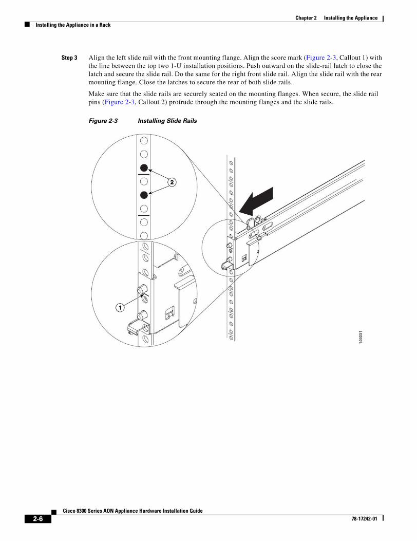
Step 3 Align the left slide rail with the front mounting flange. Align the score mark (Figure 2-3, Callout 1) with the line between the top two 1-U installation positions. Push outward on the slide-rail latch to close the latch and secure the slide rail. Do the same for the right front slide rail. Align the slide rail with the rear mounting flange. Close the latches to secure the rear of both slide rails.
Make sure that the slide rails are securely seated on the mounting flanges. When secure, the slide rail pins (Figure 2-3, Callout 2) protrude through the mounting flanges and the slide rails.
Figure 2-3 Installing Slide Rails
2-6Cisco 8300 Series AON Appliance Hardware Installation Guide
78-17242-01

Chapter 2 Installing the ApplianceInstalling the Appliance in a Rack
Step 4 Extend the slide rails fully from the rack until the slide rails lock. Align the tabs on the slide rails (Figure 2-4, Callout 1) with the matching inserts on the appliance and lower the appliance onto the slide rails.
Make sure that each slide-rail tab is inserted in the matching insert on the appliance and that the appliance is resting on the top edge of the slide rails.
Figure 2-4 Positioning Appliance on the Slide Rails
2-7Cisco 8300 Series AON Appliance Hardware Installation Guide
78-17242-01

Chapter 2 Installing the ApplianceInstalling the Appliance in a Rack
Step 5 Carefully slide the appliance along the slide rails approximately one inch toward the rack to lock the appliance on the slide rails, as shown in Figure 2-5.
Note When the appliance is locked in position, an indicator (Figure 2-5, Callout 1) is visible on each side of the appliance. Make sure that the appliance is securely attached to the slide rail hooks (Callout 2). To remove the appliance from the rack, lift up on the indicator and slide the appliance forward, then use the handles to lift the appliance out of the rack.
Figure 2-5 Ensuring Appliance Is Securely Attached
2-8Cisco 8300 Series AON Appliance Hardware Installation Guide
78-17242-01

Chapter 2 Installing the ApplianceInstalling the Appliance in a Rack
Step 6 Remove the blue handles, then slide the blue latches (Figure 2-6, Callout 1) on the slide rails in either direction and slide the appliance into the rack until it extends approximately 4 inches.
Note Retain the blue handles for future use in case the appliance needs to be removed from the rack.
Figure 2-6 Removing Handles and Sliding Appliance into Rack
2-9Cisco 8300 Series AON Appliance Hardware Installation Guide
78-17242-01

Chapter 2 Installing the ApplianceInstalling the Appliance in a Rack
Step 7 Attach the cable-management assembly to the rear of the slide rail using a hinge pin (Figure 2-7, Callout 1). Attach the free end of the cable-management assembly to the slide rail using the second hinge pin (Callout 2).
Note If you installed the cable-management-arm bracket in Step 2, complete the installation of the cable management assembly.
Figure 2-7 Attaching Cable Management Assembly
2-10Cisco 8300 Series AON Appliance Hardware Installation Guide
78-17242-01

Chapter 2 Installing the ApplianceInstalling the Appliance in a Rack
Step 8 Attach the power, data, and serial cables to the rear of the appliance. Secure the cable-restraint bracket (Figure 2-8, Callout 2) to the slide rail. If necessary, see the “Bringing the Appliance Online” section on page 3-1 to identify connectors on the rear panel.
Note Allow slack in all cables to avoid tension in the cables. Use cable clamps (Figure 2-8, Callout 3) to secure the cables across the rear of the appliance. Attach the thinner cables to the cable-restraint bracket (Callout 2) on the slide rail. Route the cables along the cable-management arm channel, securing them with cable straps (Callout 1).
Figure 2-8 Attaching Cables to the Appliance
2-11Cisco 8300 Series AON Appliance Hardware Installation Guide
78-17242-01
Chapter 2 Installing the ApplianceInstalling the Appliance in a Rack
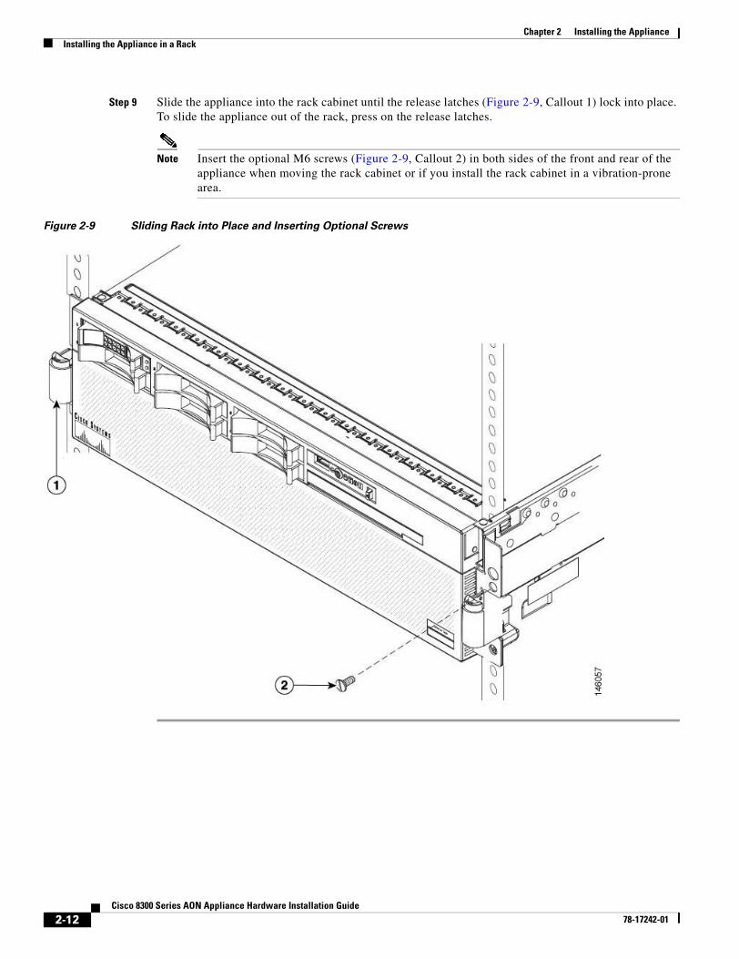
Step 9 Slide the appliance into the rack cabinet until the release latches (Figure 2-9, Callout 1) lock into place. To slide the appliance out of the rack, press on the release latches.
Note Insert the optional M6 screws (Figure 2-9, Callout 2) in both sides of the front and rear of the appliance when moving the rack cabinet or if you install the rack cabinet in a vibration-prone area.
Figure 2-9 Sliding Rack into Place and Inserting Optional Screws
2-12Cisco 8300 Series AON Appliance Hardware Installation Guide
78-17242-01

Cisco 8300 Series AON78-17242-01
C H A P T E R 3
Operating the ApplianceThis chapter describes how to identify the components and other hardware features of theCisco 8300 Series AON Appliance. It also provides information to help you troubleshoot hardware problems. It contains the following sections:
• Bringing the Appliance Online, page 3-1
• Troubleshooting Hardware Problems, page 3-4
Note This chapter covers only hardware-related topics. For pointers to detailed information on configuring software on the Cisco 8300 Series AON Appliance, see the “Related Documentation” section on page xi.
Bringing the Appliance OnlineOnce you have installed the Cisco 8300 Series AON Appliance in a rack, use the sections that follow to complete the installation and bring the appliance online:
• Identifying External Components and Connectors, page 3-2
• Connecting to AC Power, page 3-3
• Connecting to a Network, page 3-3
• Connecting a Serial Cable, page 3-4
• Where to Go Next, page 3-4
3-1 Appliance Hardware Installation Guide

Chapter 3 Operating the ApplianceBringing the Appliance Online
Identifying External Components and ConnectorsFigure 3-1 shows the indicators and controls on the front panel of the appliance.
Figure 3-1 Front Panel
Figure 3-2 shows the indicators on the operator information panel located on the front of the appliance.
Figure 3-2 Operator Information Panel
1 Hard disk drive status LED 4 Electrostatic-discharge connector
2 Hard disk drive activity LED 5 DVD drive activity LED
3 Operator information panel and latch for Light Path Diagnostics
6 DVD-eject button
1 USB connector 5 Location LED (blue)
2 Power LED (green) 6 Information LED (amber)
3 Power control button 7 System-error LED (amber)
4 Hard disk drive activity LED (green) 8 Release latch for Light Path Diagnostics
1292
51
1 2 3 4 5 6 7 8
3-2Cisco 8300 Series AON Appliance Hardware Installation Guide
78-17242-01

Chapter 3 Operating the ApplianceBringing the Appliance Online
Figure 3-3 shows the I/O and power connectors on the rear panel of the appliance.
Figure 3-3 Rear Panel I/O and Power Connectors
Note Only the four connectors listed above are used by the Cisco 8300 Series AON Appliance. Do not connect devices to other ports or connectors.
Connecting to AC PowerConnect the each of the appliance’s two power supplies to a 15 A, 120 VAC (10 A, 240 VAC) circuit with overcurrent protection.
Warning This product relies on the building's installation for short-circuit (overcurrent) protection. Ensure that the protective device is rated not greater than: 15A, 120VAC (10A, 240VAC). Statement 1005
Connecting to a NetworkThe Cisco 8300 Series AON Appliance has three Gigabit Ethernet connections. Connect an RJ-45 cable to Gigabit Ethernet 1.
Note Gigabit Ethernet 1 is the primary interface for network and management traffic. The other Ethernet interfaces are not enabled in some AON software releases. See the Cisco Application-Oriented Networking Administration Guide for information related to Ethernet interfaces and your AON software release.
1 Power supplies 4 Console serial port
2 Gigabit Ethernet 1 5 Gigabit Ethernet 3
3 Gigabit Ethernet 2
3-3Cisco 8300 Series AON Appliance Hardware Installation Guide
78-17242-01

Chapter 3 Operating the ApplianceTroubleshooting Hardware Problems
Connecting a Serial CableThe appliance has a serial console port (RJ-45). Depending on the cable and the adapter used, this port appears as a DTE or DCE device at the end of the cable.
For connection to a PC running terminal emulation software, use the RJ-45 to DB-9 adapter cable that shipped with your appliance. Connect the included serial cable to the appropriate port, as shown in Figure 3-3 on page 3-3. Then configure your terminal application with the following settings:
• 9600 baud
• 8 data bit
• N (no) parity
• 1 stop bit
Note Terminal emulation software must use ANSI display and ANSI keyboard settings to connect to the appliance.
Where to Go NextSee the following documents to complete the configuration of the Cisco 8300 Series AON Appliance:
• Cisco Application-Oriented Networking Installation Guide
• Cisco Application-Oriented Networking Administration Guide
See the “Obtaining Documentation” section on page xi for information on how to obtain documentation.
Troubleshooting Hardware ProblemsUse Light Path Diagnostics to diagnose system errors. The Light Path Diagnostics panel is inside the operator information panel, on the right front of the appliance (see Figure 3-1 on page 3-2). To access the Light Path Diagnostics panel, slide the latch to the left on the front of the Light Path Diagnostics drawer.
3-4Cisco 8300 Series AON Appliance Hardware Installation Guide
78-17242-01

Chapter 3 Operating the ApplianceTroubleshooting Hardware Problems
Figure 3-4 shows the controls and LEDs on the Light Path Diagnostics panel.
Figure 3-4 Light Path Diagnostics Panel
To acknowledge a system error but not take immediate action, press the Remind button and place Light Path Diagnostics in remind mode. When the appliance is in remind mode, the system-error LED on the front of the appliance flashes. If a new failure occurs, the system-error LED is lit again.
Press the Reset button to reset the appliance and run the power-on self-test (POST). You might have to use a pen or the end of a straightened paper clip to press the button.
The appliance is designed so that LEDs remain lit when the appliance is connected to an AC power source but is not turned on, provided that the power supply is operating correctly. This feature helps you to isolate the problem when the operating system is shut down.
Any memory, microprocessor, and VRM LED can be lit again without AC power after you remove the microprocessor tray so that you can isolate a problem. After AC power has been removed from the appliance, power remains available to these LEDs for up to 24 hours.
To view the memory, microprocessor, and VRM LEDs, press and hold the Light Path Diagnostics button on the memory card or microprocessor board to light the error LEDs. The LEDs that were lit while the appliance was running will be lit again while the button is pressed.
Using LEDs to Identify ProblemsLEDs in three locations on the appliance are available to help you diagnose problems that might occur during installation and operation of the Cisco 8300 Series AON Appliance. Use them in the following order:
1. Operator information panel—Look at this panel first. If an error has occurred, the information LED or the system-error LED is lit.
3-5Cisco 8300 Series AON Appliance Hardware Installation Guide
78-17242-01

Chapter 3 Operating the ApplianceTroubleshooting Hardware Problems
2. Light Path Diagnostics panel—Move the latch on the right front of the operator information panel to access the light path diagnostics panel. Note any LEDs that are lit, and then close the panel. For LED locations, see Figure 3-4 on page 3-5.
3. LEDs inside the appliance—To identify the component that is causing the error, note the lit LED beside or on the component.
Note Cisco does not support field replacement of most components. Only hard disk drives can be replaced in the field. Contact your Cisco support representative for other hardware issues.
Table 3-1 describes the LED indicators on the Light Path Diagnostics panel.
Table 3-1 Light Path Diagnostics Panel
Light Path Diagnostics LED Description
OVERSPEC There is insufficient power to power the system. NON RED and LOG might also be lit.
PS A power supply has failed or has been removed.
Note In redundant power configuration, the AC power LED on one power supply may be off.
LINK Not used.
CPU A CPU has failed, is missing, or has been improperly installed. Contact your Cisco support representative.
VRM A voltage regulator module has failed or is missing.
LOG Not used.
MEM A memory module has failed. The error LED on the memory card should also be lit.
NMI A hardware error has occurred. The PCI or MEM LED may also be lit.
PCI Not used.
SP Not used.
DASD A hard disk has failed or has been removed. The error LED on the failing disk drive is also lit. See the “Replacing Hard Disk Drives” section on page 3-7.
RAID The RAID adapter (ServeRAID 8i) has indicated a fault.
NONRED The system is operating without redundant power. If a power supply or its AC power source should fail, the OVERSPEC LED will light.
TEMP The system or a component has exceeded temperature specifications. The FAN LED might also be lit.
FAN A fan has failed or has been removed. A failing fan can also cause the TEMP LED to light.
PCI BRD Not used.
CPU BRD The microprocessor tray has failed.
I/O BRD The I/O board has failed.
3-6Cisco 8300 Series AON Appliance Hardware Installation Guide
78-17242-01

Chapter 3 Operating the ApplianceTroubleshooting Hardware Problems
Replacing Hard Disk DrivesComplete the following steps to replace a hard disk drive:
Step 1 Read the “Warnings” section on page 1-1 to ensure safety and to prevent equipment damage.
Step 2 Remove the defective hard disc drive from its hot-swap bay.
Step 3 Wait at least two minutes to allow time for the existing hard disk drive to spin to a stable state.
Step 4 Make sure that the tray handle on the new drive is open, then install the drive in the hot-swap bay, as shown in Figure 3-5.
Step 5 Repeat steps 2-4 for each additional hard drive that you want to replace.
Figure 3-5 Installing a Hard Disk Drive
3-7Cisco 8300 Series AON Appliance Hardware Installation Guide
78-17242-01

Chapter 3 Operating the ApplianceTroubleshooting Hardware Problems
3-8Cisco 8300 Series AON Appliance Hardware Installation Guide
78-17242-01

Cisco 8300 Series AON Ap78-17242-01
I N D E X
Numerics
1000BASETX port, warning regarding 1-2
B
battery replacement, warning regarding 1-2
C
cautions
significance of v
circuit breakers
and fuses, warning regarding 1-2
and short circuits, warning regarding 1-2
console cable specifications (see safety information, cabling specifications)
conventions, typographical v
D
documentation
conventions used in v
related xi
E
electrical codes 2-1
electrical input 1-7
electricity (see safety information)
electromagnetic interference (EMI) (see safety information)
electrostatic discharge (see safety information)
EMI (electromagnetic interference) (see safety information)
environment
air temperature 1-7
humidity 1-7
F
front panel 3-2
fuses and short circuits, warning regarding 1-2
G
ground conductor, warning regarding defeating 1-1
H
hardware installation 2-1
heat output 1-7
I
I/O connectors 3-3
L
lightning, warning regarding 1-2
Light Path Diagnostics 3-4
N
notes, significance of v
IN-9pliance Hardware Installation Guide

Index
O
Operator Information Panel 3-2
P
personnel, warning regarding proper training 1-2
pinouts (see safety information, cabling considerations)
power
systems used with CNS 2100 Series system, warning regarding 1-2
product disposal, warning regarding 1-2
R
rack-mounting the system
ensuring proper airflow 2-2
lifting the system 2-2
stabilizing the system 2-2
rear panel 3-3
reset button 3-4
S
safety cover, warning regarding 1-1
safety extra-low voltage (SELV) circuits, warning regarding 1-2
safety information
(see also cautions and warnings)
AC power considerations 1-5
cabling considerations
console cable and adapter 1-6
pinouts for console cable 1-6
rollover cable 1-7
electricity, working with 1-3
electromagnetic interference (EMI), preventing 1-4
electrostatic discharge, preventing damage from 1-3
empty slots, covering 1-4
rack-mounting the system
ensuring proper airflow 2-2
IN-10Cisco 8300 Series AON Appliance Hardware Installation Guide
lifting the system 2-2
stabilizing the system 2-2
site preparation 1-4
environment 1-4
grounding the system 1-5
site selecting 1-5
working with electricity 1-3
SELV circuits, warning regarding 1-2
serial port
connection 3-4
settings 3-4
troubleshooting 3-7
site preparation 1-1, 1-4
environment 1-4
safety guidelines 1-5
grounding the system 1-5
site selection 1-5
site selection, warning regarding 1-5
size 1-7
slide rails 2-4
slots, empty (see safety information)
T
TN power systems, warning regarding 1-2
To 1-2
troubleshooting 3-4
W
warnings
regarding
10/100 port 1-2
100BaseTX port 1-2
10BaseT port 1-2
battery replacement 1-2
circuit breakers or fuses, and short-circuits 1-2
defeating the ground conductor 1-1
fuses or circuit breakers, and short circuits 1-2
78-17242-01

Index
ground conductor, defeating 1-1
installation site selection 1-5
lightning 1-2
personnel 1-2
power systems intended for use with CNS 2100 Series system 1-2
product disposal 1-2
safety cover 1-1
safety extra-low voltage (SELV) circuits 1-2
SELV (safety extra-low voltage) circuits 1-2
short-circuiting and fuses or circuit breakers 1-2
system disposal 1-2
TN power systems 1-2
unit disposal 1-2
Cis78-17242-01
IN-11co 8300 Series AON Appliance Hardware Installation Guide