Cisco 3504 Wireless Controller Installation Guide · Cisco 3504 Wireless Controller Installation...
42
Cisco 3504 Wireless Controller Installation Guide First Published: 2017-08-16 Americas Headquarters Cisco Systems, Inc. 170 West Tasman Drive San Jose, CA 95134-1706 USA http://www.cisco.com Tel: 408 526-4000 800 553-NETS (6387) Fax: 408 527-0883
Transcript of Cisco 3504 Wireless Controller Installation Guide · Cisco 3504 Wireless Controller Installation...

Cisco 3504 Wireless Controller Installation GuideFirst Published: 2017-08-16
Americas HeadquartersCisco Systems, Inc.170 West Tasman DriveSan Jose, CA 95134-1706USAhttp://www.cisco.comTel: 408 526-4000 800 553-NETS (6387)Fax: 408 527-0883
THE SPECIFICATIONS AND INFORMATION REGARDING THE PRODUCTS IN THIS MANUAL ARE SUBJECT TO CHANGE WITHOUT NOTICE. ALL STATEMENTS,INFORMATION, AND RECOMMENDATIONS IN THIS MANUAL ARE BELIEVED TO BE ACCURATE BUT ARE PRESENTED WITHOUT WARRANTY OF ANY KIND,EXPRESS OR IMPLIED. USERS MUST TAKE FULL RESPONSIBILITY FOR THEIR APPLICATION OF ANY PRODUCTS.
THE SOFTWARE LICENSE AND LIMITEDWARRANTY FOR THE ACCOMPANYING PRODUCT ARE SET FORTH IN THE INFORMATION PACKET THAT SHIPPED WITHTHE PRODUCT AND ARE INCORPORATED HEREIN BY THIS REFERENCE. IF YOU ARE UNABLE TO LOCATE THE SOFTWARE LICENSE OR LIMITED WARRANTY,CONTACT YOUR CISCO REPRESENTATIVE FOR A COPY.
The Cisco implementation of TCP header compression is an adaptation of a program developed by the University of California, Berkeley (UCB) as part of UCB's public domain versionof the UNIX operating system. All rights reserved. Copyright © 1981, Regents of the University of California.
NOTWITHSTANDINGANYOTHERWARRANTYHEREIN, ALL DOCUMENT FILES AND SOFTWARE OF THESE SUPPLIERS ARE PROVIDED “AS IS"WITH ALL FAULTS.CISCO AND THE ABOVE-NAMED SUPPLIERS DISCLAIM ALL WARRANTIES, EXPRESSED OR IMPLIED, INCLUDING, WITHOUT LIMITATION, THOSE OFMERCHANTABILITY, FITNESS FORA PARTICULAR PURPOSEANDNONINFRINGEMENTORARISING FROMACOURSEOFDEALING, USAGE, OR TRADE PRACTICE.
IN NO EVENT SHALL CISCO OR ITS SUPPLIERS BE LIABLE FOR ANY INDIRECT, SPECIAL, CONSEQUENTIAL, OR INCIDENTAL DAMAGES, INCLUDING, WITHOUTLIMITATION, LOST PROFITS OR LOSS OR DAMAGE TO DATA ARISING OUT OF THE USE OR INABILITY TO USE THIS MANUAL, EVEN IF CISCO OR ITS SUPPLIERSHAVE BEEN ADVISED OF THE POSSIBILITY OF SUCH DAMAGES.
Any Internet Protocol (IP) addresses and phone numbers used in this document are not intended to be actual addresses and phone numbers. Any examples, command display output, networktopology diagrams, and other figures included in the document are shown for illustrative purposes only. Any use of actual IP addresses or phone numbers in illustrative content is unintentionaland coincidental.
Cisco and the Cisco logo are trademarks or registered trademarks of Cisco and/or its affiliates in the U.S. and other countries. To view a list of Cisco trademarks, go to this URL: http://www.cisco.com/go/trademarks. Third-party trademarks mentioned are the property of their respective owners. The use of the word partner does not imply a partnershiprelationship between Cisco and any other company. (1110R)
© 2017 Cisco Systems, Inc. All rights reserved.
C O N T E N T S
P r e f a c e Preface v
About this Guide v
Conventions v
Related Documentation vi
Obtaining Documentation and Submitting a Service Request vi
C H A P T E R 1 Overview of Cisco 3504 Wireless Controller 1
Summary of Cisco 3504 Wireless Controller Features 1
Platform Components 3
Cisco 3504 Wireless Controller Front Panel 3
Cisco 3504 Wireless Controller Rear Panel 6
C H A P T E R 2 Installing the Cisco 3504 Wireless Controller 7
Installation Guidelines and Safety Warnings 7
Unpacking and Inspecting the Controller 8
Package Contents 9
Requirements Tools and Information 9
Initial System Configuration Information 10
Configuring Management Interface 11
Choosing a Physical Location 12
Installing the Controller 13
Mounting the Controller 13
Mounting the Controller on Desktop or Shelf 13
Mounting the Controller on a Wall (Mounting Screws) 14
Rack Mounting the Controller 16
Connecting the Controller Console Port 19
Installing a Security Lock 19
Cisco 3504 Wireless Controller Installation Guide iii
Running the Bootup Script and Power-On Self Test 20
Using the Startup Wizard 29
Logging On to the Controller 32
Connecting to the Network 32
Connecting Access Points 33
Troubleshooting the Controller 34
A P P E N D I X A Controller Specifications 35
Physical Specifications 35
Environmental Specifications 35
Power Specifications 36
Cisco 3504 Wireless Controller Installation Guideiv
Contents
Preface
This preface describes this guide and provides information about the conventions used in this guide, andrelated documentation. It includes the following sections:
• About this Guide, page v
• Conventions, page v
• Related Documentation, page vi
• Obtaining Documentation and Submitting a Service Request, page vi
About this GuideThis guide is designed to help experienced network administrators install andminimally configure Cisco 3504Wireless Controller.
ConventionsThis document uses the following conventions for notes, cautions, and safety warnings. Notes and cautionscontain important information that you should know.
Means reader take note. Notes contain helpful suggestions or references to material not covered in themanual.
Note
Means reader be careful. Cautions contain information about something you might do that could resultin equipment damage or loss of data.
Caution
Safety warnings appear throughout this guide in procedures that, if performed incorrectly, can causephysical injuries. A warning symbol precedes each warning statement.
Warning
Cisco 3504 Wireless Controller Installation Guide v

Related Documentation• For information about Cisco Wireless Controller software, see:
http://www.cisco.com/c/en/us/support/wireless/wireless-lan-controller-software/tsd-products-support-series-home.html
• For information about the Cisco 3500 Series Wireless Controllers, see:
http://www.cisco.com/c/en/us/support/wireless/3500-series-wireless-controllers/tsd-products-support-series-home.html
• Cisco 3504 WLC Deployment Guide
• Regulatory Compliance and Safety Information
Obtaining Documentation and Submitting a Service RequestFor information on obtaining documentation, using the Cisco Bug Search Tool (BST), submitting a servicerequest, and gathering additional information, see What's New in Cisco Product Documentation.
To receive new and revised Cisco technical content directly to your desktop, you can subscribe to the What'sNew in Cisco Product Documentation RSS feed. RSS feeds are a free service.
Cisco 3504 Wireless Controller Installation Guidevi
PrefaceRelated Documentation
C H A P T E R 1Overview of Cisco 3504 Wireless Controller
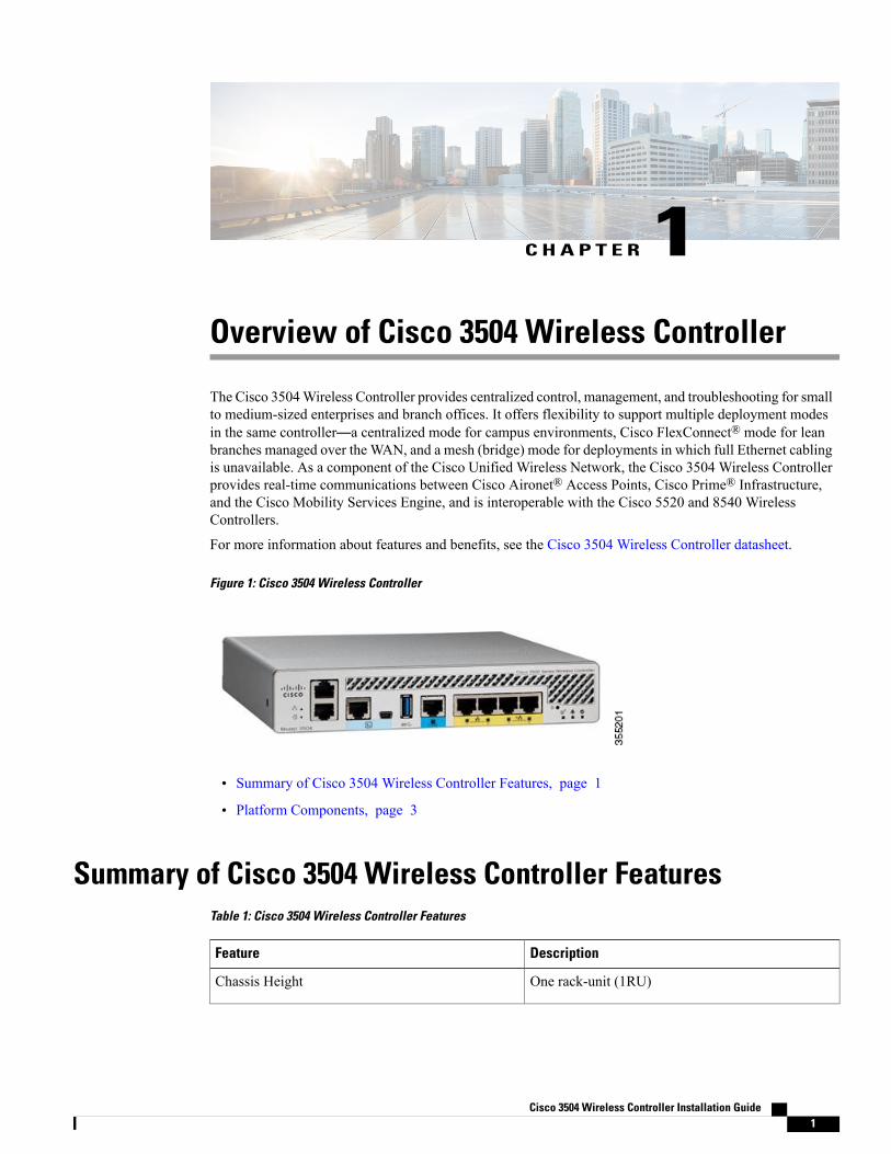
The Cisco 3504Wireless Controller provides centralized control, management, and troubleshooting for smallto medium-sized enterprises and branch offices. It offers flexibility to support multiple deployment modesin the same controller—a centralized mode for campus environments, Cisco FlexConnect® mode for leanbranches managed over the WAN, and a mesh (bridge) mode for deployments in which full Ethernet cablingis unavailable. As a component of the Cisco Unified Wireless Network, the Cisco 3504 Wireless Controllerprovides real-time communications between Cisco Aironet® Access Points, Cisco Prime® Infrastructure,and the Cisco Mobility Services Engine, and is interoperable with the Cisco 5520 and 8540 WirelessControllers.
For more information about features and benefits, see the Cisco 3504 Wireless Controller datasheet.
Figure 1: Cisco 3504 Wireless Controller
• Summary of Cisco 3504 Wireless Controller Features, page 1
• Platform Components, page 3
Summary of Cisco 3504 Wireless Controller FeaturesTable 1: Cisco 3504 Wireless Controller Features
DescriptionFeature
One rack-unit (1RU)Chassis Height
Cisco 3504 Wireless Controller Installation Guide 1

DescriptionFeature
4 Gbps
While the mGig port supports 5-Gbps PHYrate, data plane performance is limited to 4Gbps
Note
Throughput
150Number of APs supported
3000Number of clients supported
Cavium Network Processor—CN7240-AAP 8-core,1.5 GHz
Processor
• Control/Data Plane Memory—8GB DDR4
• Boot Flash—8MB SPI NOR Serial Boot
• Bulk Flash—32GB eMMC
Memory Options
2x 1G CuRedundancy, Service Ports
1x 5G/mGig Cu, 4x 1G Cu (2 ports 802.3at PSE)Data Ports
–4° F to 158° F (–20° C to 70° C)Storage Temperature
32° F to 104° F (0° C to 40° C)Operating Temperature
0% to 95% RH non-condensingStorage Humidity
5% to 95% RH non-condensingOperating Humidity
54VDC/1.05A, 12VDC/3.75APower Adapter
Cisco 3504 Wireless Controller Installation Guide2
Overview of Cisco 3504 Wireless ControllerSummary of Cisco 3504 Wireless Controller Features

Platform Components
Cisco 3504 Wireless Controller Front Panel
Figure 2: Cisco 3504 Wireless Controller Front Panel View
Table 2: Cisco 3504 Wireless Controller Front Panel Components
Service Port LED1
Redundancy Port LED2
Service Port (SP) (RJ-45) for Out-of-Band Management3
Redundancy Port (RP) (RJ-45).
The redundancy ports can be connected back to back or via an L2switch.
Note
4
CPU console port, which is an RS-232 port that supports a RJ-45 connector. At boot-up, thecontroller configures the RS-232 port as a console port with default settings of 9600, N, 8, 1. Theboot-loader supports baud rates of 1200, 2400, 4800, 9600, 19200, 38400, 57600, and 115200. Adefault baud-rate recovery mechanism is not available; however the bootloader ensures that thestored baud rate setting matches one of the allowed values before setting the baud rate. If anonstandard value is detected the baud rate will default to 9600.
5
Mini-B USB console port that can be used to perform software updates in addition to the alreadyavailable transfer modes, namely HTTP, TFTP, FTP, and SFTP.
If theMini-BUSB console port is used, the CPU console port that supports RJ-45 connectoris ignored. That is, only one of the two ports are ever active.
If you connect to both Mini-B USB port and the CPU console port, then the CPU consoleport takes precedence.
Note
6
Cisco 3504 Wireless Controller Installation Guide 3
Overview of Cisco 3504 Wireless ControllerPlatform Components
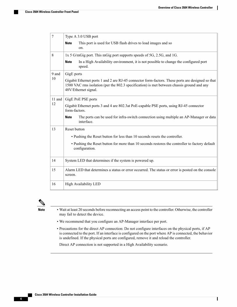
Type A 3.0 USB port
This port is used for USB flash drives to load images and soon.
Note
7
1x 5 G/mGig port. This mGig port supports speeds of 5G, 2.5G, and 1G.
In a High Availability environment, it is not possible to change the configured portspeed.
Note
8
GigE ports
Gigabit Ethernet ports 1 and 2 are RJ-45 connector form-factors. These ports are designed so that1500 VAC rms isolation (per the 802.3 specification) is met between chassis ground and any48V/Ethernet signal.
9 and10
GigE PoE PSE ports
Gigabit Ethernet ports 3 and 4 are 802.3at PoE-capable PSE ports, using RJ-45 connectorform-factors.
The ports can be used for infra-switch connection using multiple an AP-Manager or datainterface.
Note
11 and12
Reset button
• Pushing the Reset button for less than 10 seconds resets the controller.
• Pushing the Reset button for more than 10 seconds restores the controller to factory defaultconfiguration.
13
System LED that determines if the system is powered up.14
Alarm LED that determines a status or error occurred. The status or error is posted on the consolescreen.
15
High Availability LED16
Note •Wait at least 20 seconds before reconnecting an access point to the controller. Otherwise, the controllermay fail to detect the device.
•We recommend that you configure an AP-Manager interface per port.
• Precautions for the direct AP connection: Do not configure interfaces on the physical ports, if APis connected to the port. If an interface is configured on the port where AP is connected, the behavioris undefined. If the physical ports are configured, remove it and reload the controller.
Direct AP connection is not supported in a High Availability scenario.
Cisco 3504 Wireless Controller Installation Guide4
Overview of Cisco 3504 Wireless ControllerCisco 3504 Wireless Controller Front Panel
Front Panel LEDs: Definitions of States
Table 3: Cisco 3504 Wireless Controller Front Panel LEDs: Definitions of States
State DescriptionLED Name
Green or Blinking Green—Link activity
Off—No link
GigE ports
Green or Blinking Green—Link activity
Off—No link
GigE PoE PSE ports
Blinking Amber—Boot-loader is active and waitingfor user input from the system console
Blinking Green—Boot-loader or booting
Blinking Green—Boot-loader or booting
Off—System not receiving power.
System LED
Blinking Green—Controller image upgrading
Amber—Controller status activity, such as firmwareupgrade
Blinking Amber—Controller error. For example, atemperature error exists.
Alarm LED
Solid Green—HA port paired with peer controller
Slow Green Blink—Pairing/HA Standby HOT
Slow Amber Blink—Bootup (Primary/Secondary)and HA Standby COLD
Fast Blink Amber—HA maintenance
Solid Amber—Peer not found
Off—Standby/HA disabled
High Availability LED
Cisco 3504 Wireless Controller Installation Guide 5
Overview of Cisco 3504 Wireless ControllerCisco 3504 Wireless Controller Front Panel
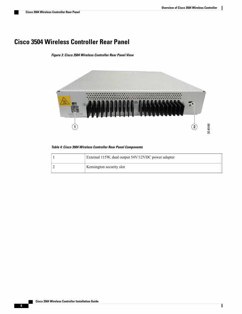
Cisco 3504 Wireless Controller Rear Panel
Figure 3: Cisco 3504 Wireless Controller Rear Panel View
Table 4: Cisco 3504 Wireless Controller Rear Panel Components
External 115W, dual output 54V/12VDC power adapter1
Kensington security slot2
Cisco 3504 Wireless Controller Installation Guide6
Overview of Cisco 3504 Wireless ControllerCisco 3504 Wireless Controller Rear Panel
C H A P T E R 2Installing the Cisco 3504 Wireless Controller
This chapter describes how to install the Cisco 3504 Wireless Controller.
IMPORTANT SAFETY INSTRUCTIONS
This warning symbol means danger. You are in a situation that could cause bodily injury. Before youwork on any equipment, be aware of the hazards involved with electrical circuitry and be familiar withstandard practices for preventing accidents. Use the statement number provided at the end of each warningto locate its translation in the translated safety warnings that accompanied this device. Statement 1071
Warning
SAVE THESE INSTRUCTIONS
• Installation Guidelines and Safety Warnings, page 7
• Unpacking and Inspecting the Controller, page 8
• Package Contents, page 9
• Requirements Tools and Information, page 9
• Initial System Configuration Information, page 10
• Configuring Management Interface, page 11
• Choosing a Physical Location, page 12
• Installing the Controller, page 13
Installation Guidelines and Safety WarningsThis section includes the basic installation guidelines and safety warning statements. Read this section beforeyou start the installation procedure. Translations of the warning statements appear in the RCSI guide onCisco.com.
• The operating environment must be within the ranges listed in Environmental Specifications , on page35.
• Cabling is away from sources of electrical noise, such as radios, power lines, and fluorescent lightingfixtures. Make sure that the cabling is safely away from other devices that might damage the cables.
Cisco 3504 Wireless Controller Installation Guide 7

• Airflow around the device and through the vents is unrestricted
• Humidity around the device does not exceed 95 percent.
• Altitude at the installation site is not greater than 10,000 feet.
• Do not place any items on the top of the device.
• For 10/100/1000 fixed ports, the cable length from a switch to a connected device cannot exceed 328feet (100 meters).
• Clearance to the switch front and rear panel meets these conditions:
◦Front-panel LEDs can be easily read.
◦Access to ports is sufficient for unrestricted cabling.
◦AC power cord can reach from the AC power outlet to the connector on the switch rear panel.
To prevent the system from overheating, do not operate it in an area that exceeds the maximumrecommended ambient temperature of: 40° C (104° F). Statement 1047.
Warning
To prevent airflow restriction, allow clearance around the ventilation openings to be at least 50 mm (5cm). Statement 1076
Warning
Read the installation instructions before connecting the system to the power source. Statement 1004.Warning
Ultimate disposal of this product should be handled according to all national laws and regulations.Statement 1040.
Warning
No user-serviceable parts inside. Do not open. Statement 1073.Warning
Installation of the equipment must comply with local and national electrical codes. Statement 1074.Warning
Hot surface. Statement 1079.Warning
Unpacking and Inspecting the ControllerFollow these steps to unpack the Cisco 3504 Wireless Controller and prepare it for operation:
Cisco 3504 Wireless Controller Installation Guide8
Installing the Cisco 3504 Wireless ControllerUnpacking and Inspecting the Controller
Procedure
Step 1 Remove the controller from its container and save all the packaging material.Step 2 Compare the shipment to the equipment list provided by your Cisco customer service representative. Verify
that you have all the items.Step 3 Check for damage and report discrepancies or damage, if any, to your Cisco customer service representative.
Before speaking to the representative, have the following information ready:
• Invoice number of shipper (see the packing slip)
• Model and serial number of the damaged unit
• Description of damage
• Effect of damage on the installation
Package ContentsEach Cisco 3504 Wireless Controller package contains the following items:
• One Cisco 3504 Wireless Controller
• One Power supply and power cord (power cord option configurable)
• Optional licenses will be pre-installed on controller at factory, if selected
• Cisco 3504 Wireless Controller software pre-loaded on the controller (software option configurable)
• Two Number 6 Phillips pan-head screws for mounting the controller on a desk, shelf, or wall
• Two wall anchors
• Four adhesive rubber feet pieces
Requirements Tools and InformationYou will need the following tools and information before you can install the controller:
•Wireless controller hardware
◦Controller with factory-supplied power cord and mounting hardware
◦Network, operating system service network, and access point cables as required
• Command-line interface (CLI) console
◦Serial terminal emulator on CLI console (PC or laptop)
◦Mini-B USB console port
◦Use either RJ-45 console cable or Mini-B USB cable to connect CLI console and controller
Cisco 3504 Wireless Controller Installation Guide 9
Installing the Cisco 3504 Wireless ControllerPackage Contents
• Local TFTP server (required for downloading operating system software updates). Cisco uses an integralTFTP server. This means that third-party TFTP servers cannot run on the same workstation as the CiscoWCS because Cisco WCS and third-party TFTP servers use the same communication port.
Initial System Configuration InformationObtain the following initial configuration parameters from your wireless LAN or network administrator:
• A system (controller name), such as controller. The system name can contain up to 32 printable ASCIIcharacters.
• An administrative username and password, which can contain up to 24 printable ASCII characters.
• You must enter a username and password and the configured username and password cannot be thesame.
• A management interface (DS Port or network interface port) IP address, such as 10.40.0.4.
• A management interface netmask address, such as 255.255.255.0.
• A management interface default router IP address, such as 10.40.0.5.
• A VLAN identifier if the management interface is assigned to a VLAN, such as 40 or 0 for an untaggedVLAN.
• Configure the management interface port mapping to either of the following:
◦Port 5 if utilizing the mGig port to the DS
◦Appropriate Gigabit port number (1-4) to the DS
• Amanagement interface DHCP server IP address, such as 10.40.0.6 (the IP address of the default DHCPserver that will supply IP addresses to clients and the management interface.
• A virtual gateway IP address (a fictitious, unassigned IP address, such as 1.1.1.1, used by all Ciscowireless controller Layer 3 security and mobility managers).
• A Cisco wireless controller mobility or RF group name, such as rfgrp40 if required. An RF group namecan contain up to 19 printable ASCII characters.
• An 802.11 network name (SSID), such as wlan1. An SSID can contain up to 32 printable, case-sensitiveASCII characters.
• DHCP bridging
•Whether or not to allow static IP addresses from clients, either Yes or No.
◦Yes is more convenient, but has lower security (session can be hijacked).
◦No is less convenient, but has higher security and works well for Windows devices.
• RADIUS server IP address, communications port, and secret if you are configuring a RADIUS server,such as 10.40.0.3, 1812, and mysecretcode.
• The country code for this installation. Enter help to see a list or refer to the CiscoWireless LANControllerConfiguration Guide for country code information. This guide is available on Cisco.com.
• Status of the 802.11 networks, either enabled or disabled.
Cisco 3504 Wireless Controller Installation Guide10
Installing the Cisco 3504 Wireless ControllerInitial System Configuration Information

• Status of Radio Resource Management (RRM), either enabled or disabled.
Configuring Management InterfaceWhen you save the controller's configuration, the controller stores it in XML format in flashmemory. Controllersoftware release 5.2 or later releases enable you to easily read and modify the configuration file by convertingit to CLI format. When you upload the configuration file to a TFTP/FTP/SFTP server, the controller initiatesthe conversion from XML to CLI. You can then read or edit the configuration file in a CLI format on theserver. When you are finished, you download the file back to the controller, where it is reconverted to anXML format and saved.
The controller does not support the uploading and downloading of port configuration CLI commands. If youwant to configure the controller ports, enter these commands:
• config port linktrap {port | all} {enable | disable}—Enables or disables the up and down link trapsfor a specific controller port or for all ports.
• configport adminmode {port | all} {enable | disable}—Enables or disables the administrative modefor a specific controller port or for all ports.
The management interface is the default interface for in-band management of the controller and connectivityto enterprise services such as AAA servers. It is also used for communications between the controller andaccess points. The management interface has the only consistently “pingable” in-band interface IP address onthe controller. You can access the GUI of the controller by entering the management interface IP address ofthe controller in the address field of either Internet Explorer or Mozilla Firefox browser.
Following are the steps to configure the management interface:
Procedure
Step 1 Enter the show interface detailed management command to view the current management interface settings.Themanagement interface uses the controller’s factory-set distribution systemMAC address.Note
Step 2 Enter the config wlan disable wlan-id command to disable each WLAN that uses the management interfacefor distribution system communication.
Step 3 Enter these commands to define the management interface:
• config interface address management ip-addr ip-netmask gateway
• config interface quarantine vlan management-interface vlan-id
Use the config interface quarantine vlanmanagement vlan_id command to configure a quarantineVLAN on the management interface.
Note
• config interface vlan management {vlan-id | 0}
Enter 0 for an untagged VLAN or a nonzero value for a tagged VLAN. We recommend usingtagged VLANs for the management interface.
Note
• config interface port management physical-ds-port-number
• config interface dhcp management primary ip-address-of-primary-dhcp-server [secondaryip-address-of-secondary-dhcp-server]
Cisco 3504 Wireless Controller Installation Guide 11
Installing the Cisco 3504 Wireless ControllerConfiguring Management Interface
• config interface acl management access-control-list-name
Step 4 Enter the save config command.Step 5 Enter the show interface detailed management command to verify that your changes have been saved.Step 6 If you made any changes to the management interface, enter the reset system command to reboot the controller
for the changes to take effect.
Choosing a Physical LocationYou can install the controller almost anywhere, but it is more secure and reliable if you install it in a secureequipment room or wiring closet. For maximum reliability, mount the controller while following theseguidelines:
• Make sure you can reach the controller and all cables attached to it.
• Make sure that water or excessive moisture cannot get into the controller.
• To prevent airflow restriction, allow clearance around the ventilation openings to be at least 50 mm (5cm).
• Verify that the ambient temperature remains between 32° F to 104° F (0° C to 40° C).
• Make sure that the controller is within 328 ft. (100 m) of equipment connected to the 10/100/1000MbpsEthernet ports.
• Make sure that the power supply adapter and the power cord can reach a 100 to 240 VAC groundedelectrical outlet.
This equipment must be grounded. Never defeat the ground conductor or operate the equipment in theabsence of a suitably installed ground conductor. Contact the appropriate electrical inspection authorityor an electrician if you are uncertain that suitable grounding is available. Statement 1024.
Warning
This product relies on the building’s installation for short-circuit (overcurrent) protection. Ensure that theprotective device is rated not greater than 20A. Statement 1005.
Warning
Cisco 3504 Wireless Controller Installation Guide12
Installing the Cisco 3504 Wireless ControllerChoosing a Physical Location

Installing the Controller
Mounting the Controller
Mounting the Controller on Desktop or ShelfBefore mounting the controller on a desktop or shelf, install the rubber feet located in accessory kit shippedwith the controller.
To install the rubber feet to the controller, follow these steps:
Procedure
Step 1 Locate the rubber feet on the black adhesive strip that is shipped with the controller.
Figure 4: Identifying the Rubber Feet
Black adhesive strip2Rubber feet1
Cisco 3504 Wireless Controller Installation Guide 13
Installing the Cisco 3504 Wireless ControllerInstalling the Controller
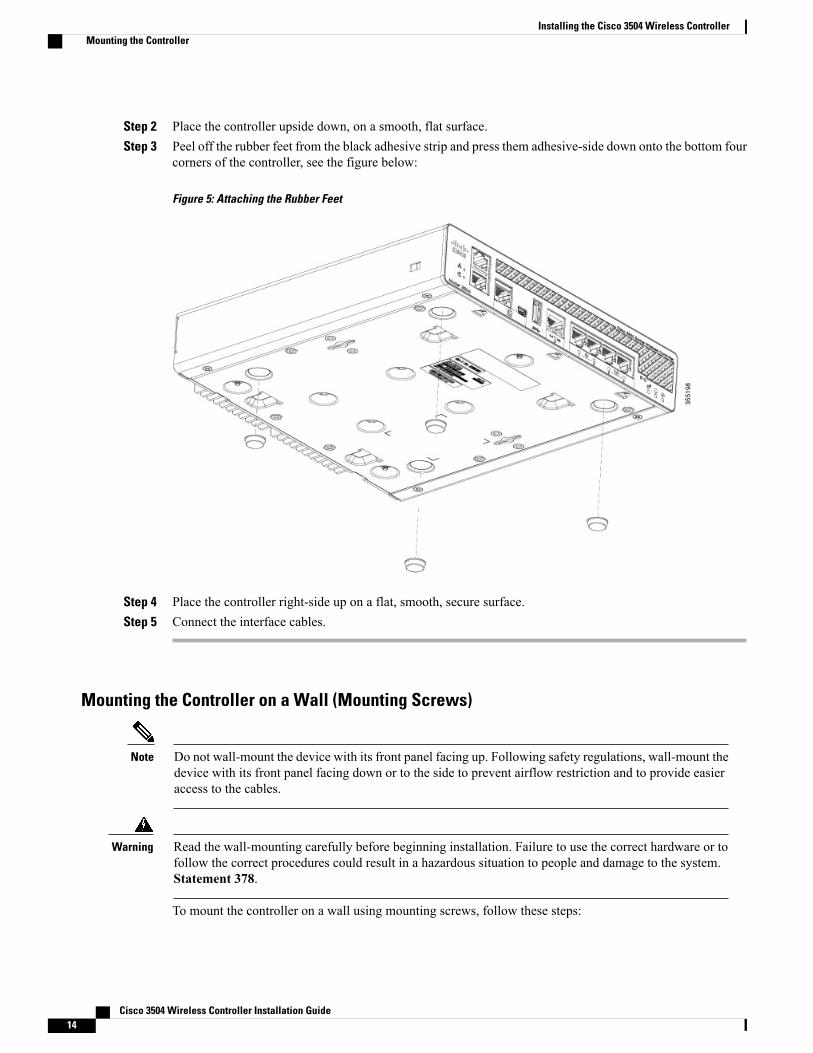
Step 2 Place the controller upside down, on a smooth, flat surface.Step 3 Peel off the rubber feet from the black adhesive strip and press them adhesive-side down onto the bottom four
corners of the controller, see the figure below:
Figure 5: Attaching the Rubber Feet
Step 4 Place the controller right-side up on a flat, smooth, secure surface.Step 5 Connect the interface cables.
Mounting the Controller on a Wall (Mounting Screws)
Do not wall-mount the device with its front panel facing up. Following safety regulations, wall-mount thedevice with its front panel facing down or to the side to prevent airflow restriction and to provide easieraccess to the cables.
Note
Read the wall-mounting carefully before beginning installation. Failure to use the correct hardware or tofollow the correct procedures could result in a hazardous situation to people and damage to the system.Statement 378.
Warning
To mount the controller on a wall using mounting screws, follow these steps:
Cisco 3504 Wireless Controller Installation Guide14
Installing the Cisco 3504 Wireless ControllerMounting the Controller
Procedure
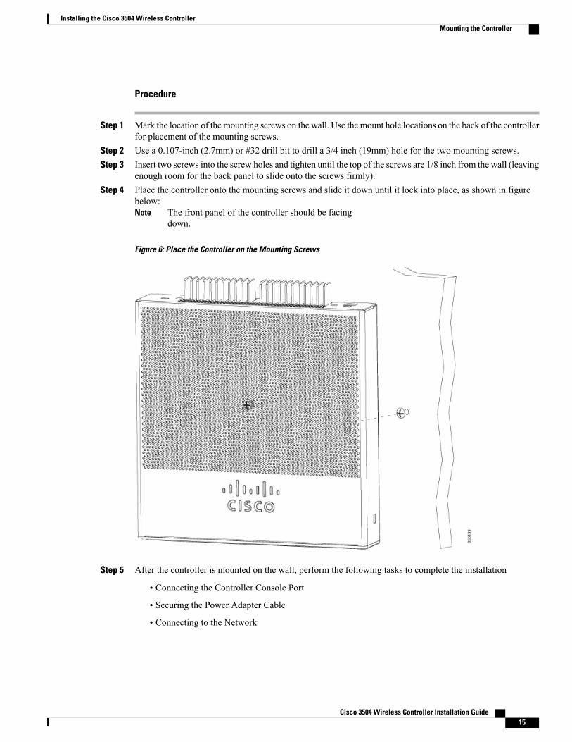
Step 1 Mark the location of the mounting screws on the wall. Use the mount hole locations on the back of the controllerfor placement of the mounting screws.
Step 2 Use a 0.107-inch (2.7mm) or #32 drill bit to drill a 3/4 inch (19mm) hole for the two mounting screws.Step 3 Insert two screws into the screw holes and tighten until the top of the screws are 1/8 inch from the wall (leaving
enough room for the back panel to slide onto the screws firmly).Step 4 Place the controller onto the mounting screws and slide it down until it lock into place, as shown in figure
below:The front panel of the controller should be facingdown.
Note
Figure 6: Place the Controller on the Mounting Screws
Step 5 After the controller is mounted on the wall, perform the following tasks to complete the installation
• Connecting the Controller Console Port
• Securing the Power Adapter Cable
• Connecting to the Network
Cisco 3504 Wireless Controller Installation Guide 15
Installing the Cisco 3504 Wireless ControllerMounting the Controller

Step 6 For configuration instructions about using the CLI setup program, see the (Link to Running the Bootup scriptsection).
Rack Mounting the Controller
To prevent bodily injury when mounting or servicing this unit in a rack, you must take special precautionsto ensure that the system remains stable. The following guidelines are provided to ensure your safety:
Warning
• This unit should be mounted at the bottom of the rack if it is the only unit in the rack.
•When mounting this unit in a partially filled rack, load the rack from the bottom to the top with theheaviest component at the bottom of the rack.
• If the rack is provided with stabilizing devices, install the stabilizers before mounting or servicingthe unit in the rack.
Statement 1006
Take care when connecting units to the supply circuit so that wiring is not overloaded. Statement 1018.Warning
To mount the controller in a 19-inch equipment rack, you can order an optional Optional Rack Mount kit(AIR-CT3504-RMNT= Cisco 3504 Wireless Controller Rack Mount Tray).
The rack-mount tray is designed for tool-less assembly. To rack-mount the controller, perform the followingsteps:
Procedure
Step 1 Remove the four rubber feet if previously installed.Step 2 Slide the Cisco 3504 Wireless Controller in position such that the 4-tray tabs align and latch into the bottom
of the unit as it is pushed in place. The front of the Cisco 3504 Wireless Controller should be flush against
Cisco 3504 Wireless Controller Installation Guide16
Installing the Cisco 3504 Wireless ControllerMounting the Controller
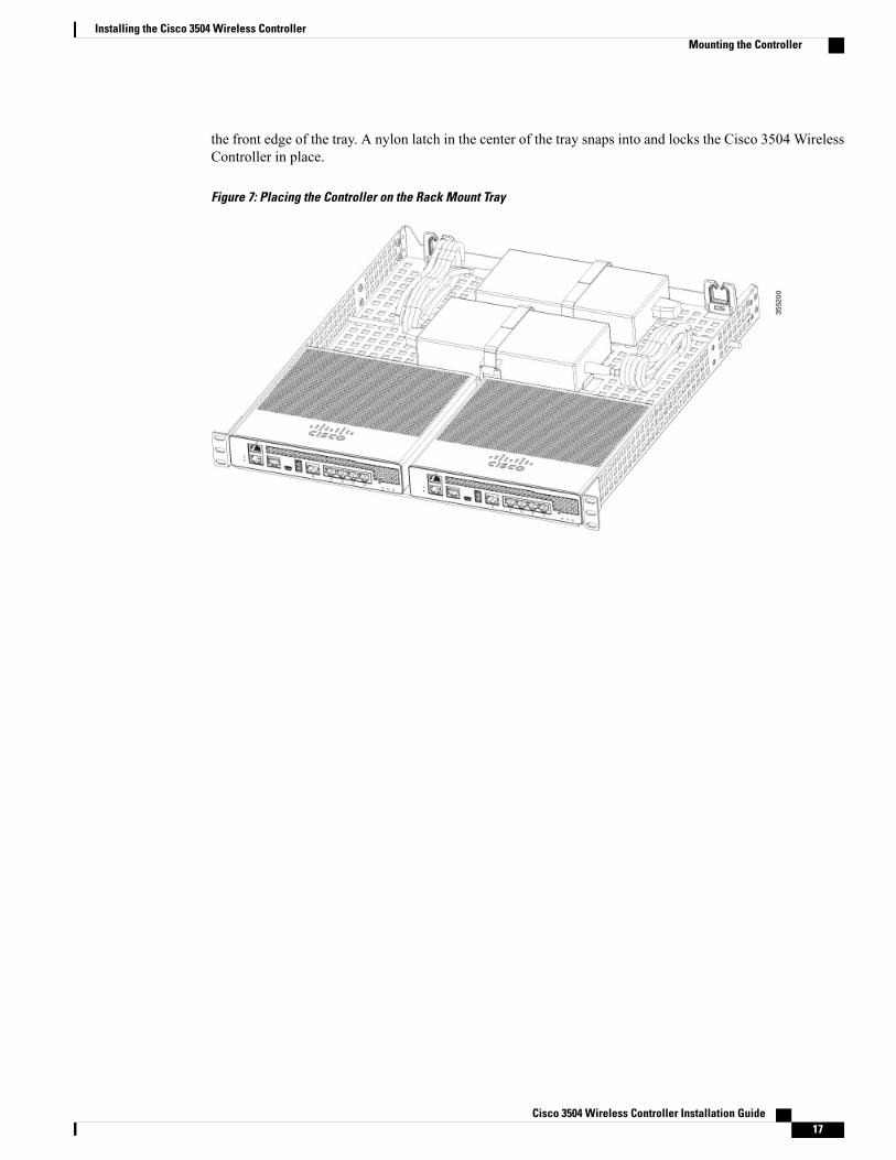
the front edge of the tray. A nylon latch in the center of the tray snaps into and locks the Cisco 3504 WirelessController in place.
Figure 7: Placing the Controller on the Rack Mount Tray
Cisco 3504 Wireless Controller Installation Guide 17
Installing the Cisco 3504 Wireless ControllerMounting the Controller

Step 3 Place the power adapters between either of the two tabs in the rear of the tray and use the provided velcrostraps to secure them.
Step 4 Route the AC wiring through the cable management clips.Step 5 Attach the rack mount tray to the rack using the supplied screws, as shown in figure below:
Figure 8: Attaching the Rack Mount Tray to the Rack
To remove the chassis from the rack, remove the screws that attach the chassis to the rack, and then removethe chassis.
Step 6 If required, install rear rack mount braces for additional stability.Include optional orderable rear rack mount adapter kit: 53-3544-05 ACCKIT, SPARE PART, RKMNT,REAR, C4948E(-F).
Reuse 69-2237-05 or later, MECHKIT, ACCY,RKMNT, REAR, C4948E(-F) (or equivalent) mountingadapters to provide additional rear tray support when rack mounted in standard or deep 4-post rack.
Cisco 3504 Wireless Controller Installation Guide18
Installing the Cisco 3504 Wireless ControllerMounting the Controller

Connecting the Controller Console Port
Do not connect a Power over Ethernet (PoE) cable to the console port. Doing so might damage thecontroller.
Caution
Install the USB device driver before establishing a physical connection between the router and the PCusing the USB Console cable plugged into the USB serial port, otherwise the connection will fail.
Note
Procedure
Step 1 Perform either of the following tasks:
• Connect the end of the console cable with the RJ-45 connector to the console port on the controller.
• Connect a Mini-B USB cable to the Mini-B USB console port. If you are using the USB serial port forthe first time on a Windows-based computer, ensure that you have installed the USB driver.
It is not possible to to use both the Mini-B USB console port and the CPU console port concurrently.If both the ports are connected, the USB port takes precedence over the CPU console port.
Note
Step 2 Connect the end of the cable with the DB-9 connector (or USB Type-A) to the terminal or PC. If your terminalor PC has a console port that does not accommodate a DB-9 connector, you must provide an appropriateadapter for that port.
Step 3 To communicate with the controller, start a terminal emulator application. This software should be configuredwith the following parameters:
• 9600 baud
• 8 data bits
• No parity
• No flow control
• 1 stop bit
Installing a Security LockThe controller has a security slot on the back panel. You can install an optional customer-supplied Kensingtonlock, such as the type that is used to secure a laptop computer, to secure the controller. See Figure 3: Cisco3504 Wireless Controller Rear Panel View, on page 6 for the location of the security lock.
Cisco 3504 Wireless Controller Installation Guide 19
Installing the Cisco 3504 Wireless ControllerConnecting the Controller Console Port

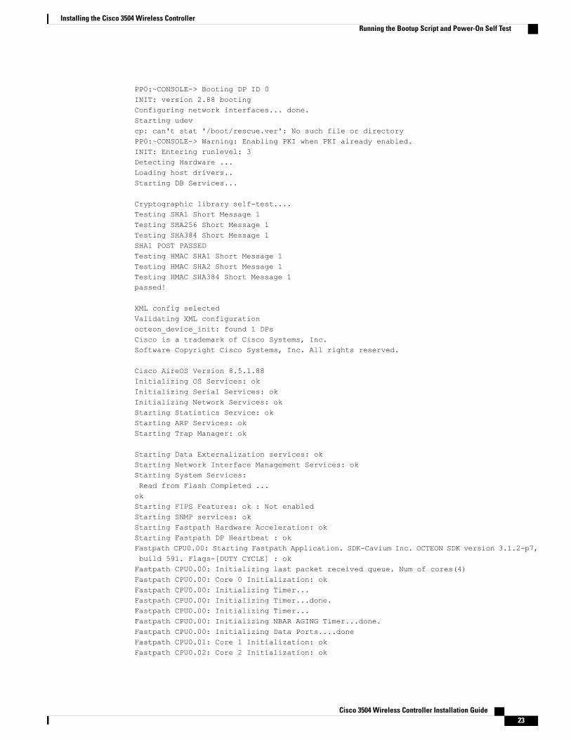
Running the Bootup Script and Power-On Self TestWhen you plug the controller into an AC power source, the bootup script initializes the system, verifies thehardware configuration, loads its microcode into memory, verifies its operating system software load, andinitializes itself with its stored configurations. Before performing this test, you should have connected yourPC to the CLI console on the controller as described in the Connecting to Console Port section.
To run the bootup script and conduct the power-on self test (POST), follow these steps:
Procedure
Step 1 Plug the external power supply into the power jack on the back of the controller.Step 2 Plug a country-specific power cord into the external power supply, then plug the other end into a grounded
100 to 240 VAC, 50–60 Hz electrical outlet.If you wish to run a previous release of the controller code, press Esc when the boot loader promptappears. The Bootloader Options menu appears.
Note
When the controller receives power, the green front panel multicolor system LED lights. If the systemLED does not light, ensure that the electrical outlet is supplying power and that the power connectionsto the controller are correct.
Note
Step 3 Observe the bootup using the CLI screen.The bootup script displays operating system software initialization (code download and POST verification)and basic configuration as shown in the following bootup display example:
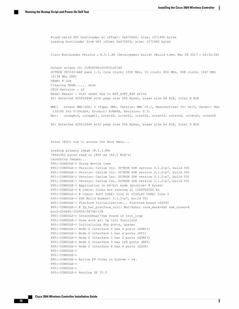
Cisco bootloader . . SPI ID: xx:xx:xx:xx:xxHeader 1 found at offset 0x40000Header 2 found at offset 0xb0000Header 3 found at offset 0x400000Header 4 found at offset 0x470000failsafe value = 0Set to Boot from NormalFound bootloaders, booting bootloader 3 of 4 at offset 0x400000.Starting next bootloader at 0xffffffff81000000.
Cisco BootLoader Version : 8.5.1.88 (Development build) (Build time: Mar 08 2017 - 20:32:41)
Octeon unique ID: 01800090c019f31e018fN0.LMC0 Configuration Completed: 8192 MBWarning: Board descriptor tuple not found in eeprom, using defaultsOCTEON CN7240-AAP pass 1.2, Core clock: 1500 MHz, IO clock: 800 MHz, DDR clock: 1067 MHz(2134 Mhz DDR)DRAM: 8 GiBClearing DRAM...... donefailsafe value = 0Found valid SPI bootloader at offset: 0xb0000, size: 1571960 bytes Found valid SPI bootloaderat offset: 0x470000, size: 1571960 bytes Loading bootloader from SPI offset 0x470000, size:1571960 bytes
Cisco BootLoader Version : 8.5.1.88 (Development build) (Build time: Mar 08 2017 - 20:32:06)
Cisco 3504 Wireless Controller Installation Guide20
Installing the Cisco 3504 Wireless ControllerRunning the Bootup Script and Power-On Self Test

Octeon unique ID: 01800090c019f31e018fOCTEON CN7240-AAP pass 1.2, Core clock: 1500 MHz, IO clock: 800 MHz, DDR clock: 1067 MHz(2134 Mhz DDR)DRAM: 8 GiBClearing DRAM...... done CPLD Revision : a2 Reset Reason : Softreset due to RST_SOFT_RST write SF: Detected S25FL064P with page size 256Bytes, erase size 64 KiB, total 8 MiBMMC: Octeon MMC/SD0: 0 (Type: MMC, Version: MMC v5.1, Manufacturer ID: 0x15, Vendor: Man150100 Snr 0739c2b4, Product: BJNB4R, Revision: 0.7)Net: octmgmt0, octmgmt1, octeth0, octeth1, octeth2, octeth3, octeth4, octeth5, octeth6SF: Detected S25FL064P with page size 256 Bytes, erase size 64 KiB, total 8 MiB
Press <ESC> now to access the Boot Menu...
============================================================Boot Loader Menu - Unlocked============================================================
1. Run primary image (8.5.1.88) - Active2. Run backup image (8.5.1.92)3. Change active boot image4. Clear configuration5. Manually update images6. Run network image via TFTP7. Run diagnostic image from FLASH8. Exit from menu system to boot loader prompt
------------------------------------------------------------Enter selection:
Cisco bootloader . . SPI ID: xx:xx:xx:xx:xxHeader 1 found at offset 0x40000Header 2 found at offset 0xb0000Header 3 found at offset 0x400000Header 4 found at offset 0x470000failsafe value = 0Set to Boot from NormalFound bootloaders, booting bootloader 3 of 4 at offset 0x400000.Starting next bootloader at 0xffffffff81000000.Cisco BootLoader Version : 8.5.1.88 (Development build) (Build time: Mar 08 2017 - 20:32:41)
Octeon unique ID: 01800090c019f31e018fN0.LMC0 Configuration Completed: 8192 MBWarning: Board descriptor tuple not found in eeprom, using defaultsOCTEON CN7240-AAP pass 1.2, Core clock: 1500 MHz, IO clock: 800 MHz, DDR clock: 1067 MHz(2134 Mhz DDR)DRAM: 8 GiBClearing DRAM...... donefailsafe value = 0
Cisco 3504 Wireless Controller Installation Guide 21
Installing the Cisco 3504 Wireless ControllerRunning the Bootup Script and Power-On Self Test

Found valid SPI bootloader at offset: 0xb0000, size: 1571960 bytesFound valid SPI bootloader at offset: 0x470000, size: 1571960 bytesLoading bootloader from SPI offset 0x470000, size: 1571960 bytes
Cisco BootLoader Version : 8.5.1.88 (Development build) (Build time: Mar 08 2017 - 20:32:06)
Octeon unique ID: 01800090c019f31e018fOCTEON CN7240-AAP pass 1.2, Core clock: 1500 MHz, IO clock: 800 MHz, DDR clock: 1067 MHz(2134 Mhz DDR)DRAM: 8 GiBClearing DRAM...... doneCPLD Revision : a2Reset Reason : Soft reset due to RST_SOFT_RST writeSF: Detected S25FL064P with page size 256 Bytes, erase size 64 KiB, total 8 MiB
MMC: Octeon MMC/SD0: 0 (Type: MMC, Version: MMC v5.1, Manufacturer ID: 0x15, Vendor: Man150100 Snr 0739c2b4, Product: BJNB4R, Revision: 0.7)Net: octmgmt0, octmgmt1, octeth0, octeth1, octeth2, octeth3, octeth4, octeth5, octeth6
SF: Detected S25FL064P with page size 256 Bytes, erase size 64 KiB, total 8 MiB
Press <ESC> now to access the Boot Menu...
Loading primary image (8.5.1.88)76661462 bytes read in 1805 ms (40.5 MiB/s)Launching images...PP0:~CONSOLE-> Using device treePP0:~CONSOLE-> Version: Cavium Inc. OCTEON SDK version 3.1.2-p7, build 591PP2:~CONSOLE-> Version: Cavium Inc. OCTEON SDK version 3.1.2-p7, build 591PP1:~CONSOLE-> Version: Cavium Inc. OCTEON SDK version 3.1.2-p7, build 591PP3:~CONSOLE-> Version: Cavium Inc. OCTEON SDK version 3.1.2-p7, build 591PP0:~CONSOLE-> Application in 64-bit mode (ptrsize= 8 bytes)PP0:~CONSOLE-> # cvmcs: Cores are running at 1500000000 HzPP0:~CONSOLE-> # cvmcs: BOOT CORE: Core 0; DISPLAY CORE: Core 3PP0:~CONSOLE-> SDK Build Number: 3.1.2-p7, build 591PP0:~CONSOLE-> Platform Initialization... Platform board =24590PP0:~CONSOLE-> # fp_hal_platform_init: WLC-Kukri core_mask=0xf num_cores=4pool=204800/102400/34794/128PP0:~CONSOLE-> Octeon68xx/73xx found in init_irqsPP0:~CONSOLE-> Done with all fp init functionsPP0:~CONSOLE-> Initializing Phy ports, queuesPP0:~CONSOLE-> Node 0 Interface 0 has 4 ports (SGMII)PP0:~CONSOLE-> Node 0 Interface 1 has 4 ports (XFI)PP0:~CONSOLE-> Node 0 Interface 2 has 2 ports (SGMII)PP0:~CONSOLE-> Node 0 Interface 3 has 128 ports (NPI)PP0:~CONSOLE-> Node 0 Interface 4 has 4 ports (LOOP)PP0:~CONSOLE->PP0:~CONSOLE->PP0:~CONSOLE-> Active FP Cores in System = 04.PP0:~CONSOLE->PP0:~CONSOLE->
Cisco 3504 Wireless Controller Installation Guide22
Installing the Cisco 3504 Wireless ControllerRunning the Bootup Script and Power-On Self Test
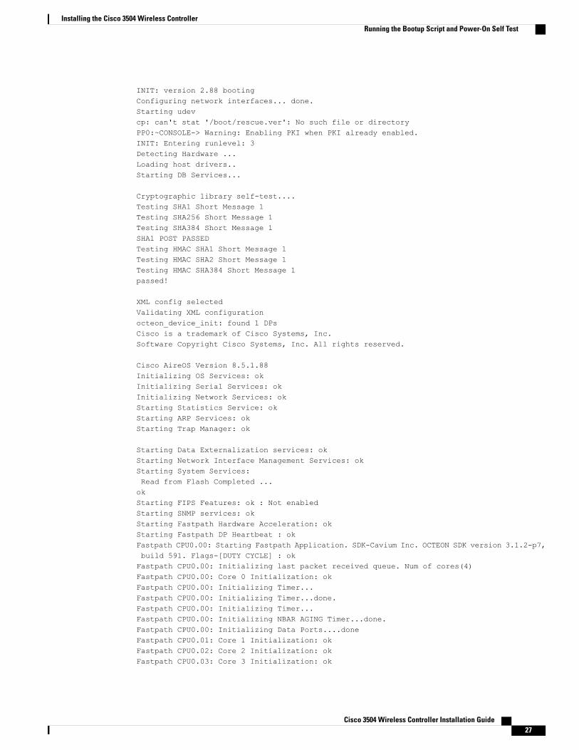
PP0:~CONSOLE-> Booting DP ID 0INIT: version 2.88 bootingConfiguring network interfaces... done.Starting udevcp: can't stat '/boot/rescue.ver': No such file or directoryPP0:~CONSOLE-> Warning: Enabling PKI when PKI already enabled.INIT: Entering runlevel: 3Detecting Hardware ...Loading host drivers..Starting DB Services...
Cryptographic library self-test....Testing SHA1 Short Message 1Testing SHA256 Short Message 1Testing SHA384 Short Message 1SHA1 POST PASSEDTesting HMAC SHA1 Short Message 1Testing HMAC SHA2 Short Message 1Testing HMAC SHA384 Short Message 1passed!
XML config selectedValidating XML configurationocteon_device_init: found 1 DPsCisco is a trademark of Cisco Systems, Inc.Software Copyright Cisco Systems, Inc. All rights reserved.
Cisco AireOS Version 8.5.1.88Initializing OS Services: okInitializing Serial Services: okInitializing Network Services: okStarting Statistics Service: okStarting ARP Services: okStarting Trap Manager: ok
Starting Data Externalization services: okStarting Network Interface Management Services: okStarting System Services:Read from Flash Completed ...okStarting FIPS Features: ok : Not enabledStarting SNMP services: okStarting Fastpath Hardware Acceleration: okStarting Fastpath DP Heartbeat : okFastpath CPU0.00: Starting Fastpath Application. SDK-Cavium Inc. OCTEON SDK version 3.1.2-p7,build 591. Flags-[DUTY CYCLE] : okFastpath CPU0.00: Initializing last packet received queue. Num of cores(4)Fastpath CPU0.00: Core 0 Initialization: okFastpath CPU0.00: Initializing Timer...Fastpath CPU0.00: Initializing Timer...done.Fastpath CPU0.00: Initializing Timer...Fastpath CPU0.00: Initializing NBAR AGING Timer...done.Fastpath CPU0.00: Initializing Data Ports....doneFastpath CPU0.01: Core 1 Initialization: okFastpath CPU0.02: Core 2 Initialization: ok
Cisco 3504 Wireless Controller Installation Guide 23
Installing the Cisco 3504 Wireless ControllerRunning the Bootup Script and Power-On Self Test

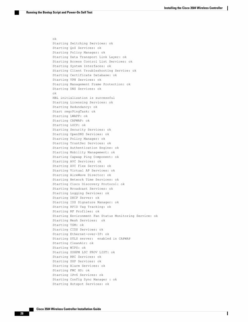
Fastpath CPU0.03: Core 3 Initialization: okokStarting Switching Services: okStarting QoS Services: okStarting Policy Manager: okStarting Data Transport Link Layer: okStarting Access Control List Services: okStarting System Interfaces: okStarting Client Troubleshooting Service: okStarting Certificate Database: okStarting VPN Services: okStarting Management Frame Protection: okStarting DNS Services: okokHBL initialization is successfulStarting Licensing Services: okStarting Redundancy: okStart rmgrPingTask: okStarting LWAPP: okStarting CAPWAP: okStarting LOCP: okStarting Security Services: okStarting OpenDNS Services: okStarting Policy Manager: okStarting TrustSec Services: okStarting Authentication Engine: okStarting Mobility Management: okStarting Capwap Ping Component: okStarting AVC Services: okStarting AVC Flex Services: okStarting Virtual AP Services: okStarting AireWave Director: okStarting Network Time Services: okStarting Cisco Discovery Protocol: okStarting Broadcast Services: okStarting Logging Services: okStarting DHCP Server: okStarting IDS Signature Manager: okStarting RFID Tag Tracking: okStarting RF Profiles: okStarting Environment Fan Status Monitoring Service: okStarting Mesh Services: okStarting TSM: okStarting CIDS Services: okStarting Ethernet-over-IP: okStarting DTLS server: enabled in CAPWAPStarting CleanAir: okStarting WIPS: okStarting SSHPM LSC PROV LIST: okStarting RRC Services: okStarting SXP Services: okStarting Alarm Services: okStarting FMC HS: okStarting IPv6 Services: okStarting Config Sync Manager : ok
Cisco 3504 Wireless Controller Installation Guide24
Installing the Cisco 3504 Wireless ControllerRunning the Bootup Script and Power-On Self Test

Starting Hotspot Services: okStarting Tunnel Services New: okStarting PMIP Services: okStarting Portal Server Services: okStarting mDNS Services: okStarting Management Services:
Web Server: CLI: Secure Web: okStarting IPSec Profiles component: okStarting FEW Services: okStarting MS Agent Services: okSemaphore priority is larger than limit of 640Starting Fabric Services: ok
(Cisco Controller)>
Step 4 If desired, press Esc key to interrupt the boot process and access the Boot menu.Step 5 Continue booting the controller or press Esc to access the following menu:
1. Run primary image (8.5.1.88) - Active2. Run backup image (8.5.1.92)3. Change active boot image4. Clear configuration5. Manually update images6. Run network image via TFTP7. Run diagnostic image from FLASH8. Exit from menu system to boot loader prompt
------------------------------------------------------------Enter selection:
If you did not press Esc, the boot process continues and takes two to three minutes. Do not reboot the controlleruntil the user login prompt appears.
Cisco bootloader . . SPI ID: xx:xx:xx:xx:xxHeader 1 found at offset 0x40000Header 2 found at offset 0xb0000Header 3 found at offset 0x400000Header 4 found at offset 0x470000failsafe value = 0Set to Boot from NormalFound bootloaders, booting bootloader 3 of 4 at offset 0x400000.Starting next bootloader at 0xffffffff81000000.Cisco BootLoader Version : 8.5.1.88 (Development build) (Build time: Mar 08 2017 - 20:32:41)
Octeon unique ID: 01800090c019f31e018fN0.LMC0 Configuration Completed: 8192 MBWarning: Board descriptor tuple not found in eeprom, using defaultsOCTEON CN7240-AAP pass 1.2, Core clock: 1500 MHz, IO clock: 800 MHz, DDR clock: 1067 MHz(2134 Mhz DDR)DRAM: 8 GiBClearing DRAM...... donefailsafe value = 0Found valid SPI bootloader at offset: 0xb0000, size: 1571960 bytes
Cisco 3504 Wireless Controller Installation Guide 25
Installing the Cisco 3504 Wireless ControllerRunning the Bootup Script and Power-On Self Test
Found valid SPI bootloader at offset: 0x470000, size: 1571960 bytesLoading bootloader from SPI offset 0x470000, size: 1571960 bytes
Cisco BootLoader Version : 8.5.1.88 (Development build) (Build time: Mar 08 2017 - 20:32:06)
Octeon unique ID: 01800090c019f31e018fOCTEON CN7240-AAP pass 1.2, Core clock: 1500 MHz, IO clock: 800 MHz, DDR clock: 1067 MHz(2134 Mhz DDR)DRAM: 8 GiBClearing DRAM...... doneCPLD Revision : a2Reset Reason : Soft reset due to RST_SOFT_RST writeSF: Detected S25FL064P with page size 256 Bytes, erase size 64 KiB, total 8 MiB
MMC: Octeon MMC/SD0: 0 (Type: MMC, Version: MMC v5.1, Manufacturer ID: 0x15, Vendor: Man150100 Snr 0739c2b4, Product: BJNB4R, Revision: 0.7)Net: octmgmt0, octmgmt1, octeth0, octeth1, octeth2, octeth3, octeth4, octeth5, octeth6
SF: Detected S25FL064P with page size 256 Bytes, erase size 64 KiB, total 8 MiB
Press <ESC> now to access the Boot Menu...
Loading primary image (8.5.1.88)76661462 bytes read in 1805 ms (40.5 MiB/s)Launching images...PP0:~CONSOLE-> Using device treePP0:~CONSOLE-> Version: Cavium Inc. OCTEON SDK version 3.1.2-p7, build 591PP2:~CONSOLE-> Version: Cavium Inc. OCTEON SDK version 3.1.2-p7, build 591PP1:~CONSOLE-> Version: Cavium Inc. OCTEON SDK version 3.1.2-p7, build 591PP3:~CONSOLE-> Version: Cavium Inc. OCTEON SDK version 3.1.2-p7, build 591PP0:~CONSOLE-> Application in 64-bit mode (ptrsize= 8 bytes)PP0:~CONSOLE-> # cvmcs: Cores are running at 1500000000 HzPP0:~CONSOLE-> # cvmcs: BOOT CORE: Core 0; DISPLAY CORE: Core 3PP0:~CONSOLE-> SDK Build Number: 3.1.2-p7, build 591PP0:~CONSOLE-> Platform Initialization... Platform board =24590PP0:~CONSOLE-> # fp_hal_platform_init: WLC-Kukri core_mask=0xf num_cores=4pool=204800/102400/34794/128PP0:~CONSOLE-> Octeon68xx/73xx found in init_irqsPP0:~CONSOLE-> Done with all fp init functionsPP0:~CONSOLE-> Initializing Phy ports, queuesPP0:~CONSOLE-> Node 0 Interface 0 has 4 ports (SGMII)PP0:~CONSOLE-> Node 0 Interface 1 has 4 ports (XFI)PP0:~CONSOLE-> Node 0 Interface 2 has 2 ports (SGMII)PP0:~CONSOLE-> Node 0 Interface 3 has 128 ports (NPI)PP0:~CONSOLE-> Node 0 Interface 4 has 4 ports (LOOP)PP0:~CONSOLE->PP0:~CONSOLE->PP0:~CONSOLE-> Active FP Cores in System = 04.PP0:~CONSOLE->PP0:~CONSOLE->PP0:~CONSOLE-> Booting DP ID 0
Cisco 3504 Wireless Controller Installation Guide26
Installing the Cisco 3504 Wireless ControllerRunning the Bootup Script and Power-On Self Test
INIT: version 2.88 bootingConfiguring network interfaces... done.Starting udevcp: can't stat '/boot/rescue.ver': No such file or directoryPP0:~CONSOLE-> Warning: Enabling PKI when PKI already enabled.INIT: Entering runlevel: 3Detecting Hardware ...Loading host drivers..Starting DB Services...
Cryptographic library self-test....Testing SHA1 Short Message 1Testing SHA256 Short Message 1Testing SHA384 Short Message 1SHA1 POST PASSEDTesting HMAC SHA1 Short Message 1Testing HMAC SHA2 Short Message 1Testing HMAC SHA384 Short Message 1passed!
XML config selectedValidating XML configurationocteon_device_init: found 1 DPsCisco is a trademark of Cisco Systems, Inc.Software Copyright Cisco Systems, Inc. All rights reserved.
Cisco AireOS Version 8.5.1.88Initializing OS Services: okInitializing Serial Services: okInitializing Network Services: okStarting Statistics Service: okStarting ARP Services: okStarting Trap Manager: ok
Starting Data Externalization services: okStarting Network Interface Management Services: okStarting System Services:Read from Flash Completed ...okStarting FIPS Features: ok : Not enabledStarting SNMP services: okStarting Fastpath Hardware Acceleration: okStarting Fastpath DP Heartbeat : okFastpath CPU0.00: Starting Fastpath Application. SDK-Cavium Inc. OCTEON SDK version 3.1.2-p7,build 591. Flags-[DUTY CYCLE] : okFastpath CPU0.00: Initializing last packet received queue. Num of cores(4)Fastpath CPU0.00: Core 0 Initialization: okFastpath CPU0.00: Initializing Timer...Fastpath CPU0.00: Initializing Timer...done.Fastpath CPU0.00: Initializing Timer...Fastpath CPU0.00: Initializing NBAR AGING Timer...done.Fastpath CPU0.00: Initializing Data Ports....doneFastpath CPU0.01: Core 1 Initialization: okFastpath CPU0.02: Core 2 Initialization: okFastpath CPU0.03: Core 3 Initialization: ok
Cisco 3504 Wireless Controller Installation Guide 27
Installing the Cisco 3504 Wireless ControllerRunning the Bootup Script and Power-On Self Test
okStarting Switching Services: okStarting QoS Services: okStarting Policy Manager: okStarting Data Transport Link Layer: okStarting Access Control List Services: okStarting System Interfaces: okStarting Client Troubleshooting Service: okStarting Certificate Database: okStarting VPN Services: okStarting Management Frame Protection: okStarting DNS Services: okokHBL initialization is successfulStarting Licensing Services: okStarting Redundancy: okStart rmgrPingTask: okStarting LWAPP: okStarting CAPWAP: okStarting LOCP: okStarting Security Services: okStarting OpenDNS Services: okStarting Policy Manager: okStarting TrustSec Services: okStarting Authentication Engine: okStarting Mobility Management: okStarting Capwap Ping Component: okStarting AVC Services: okStarting AVC Flex Services: okStarting Virtual AP Services: okStarting AireWave Director: okStarting Network Time Services: okStarting Cisco Discovery Protocol: okStarting Broadcast Services: okStarting Logging Services: okStarting DHCP Server: okStarting IDS Signature Manager: okStarting RFID Tag Tracking: okStarting RF Profiles: okStarting Environment Fan Status Monitoring Service: okStarting Mesh Services: okStarting TSM: okStarting CIDS Services: okStarting Ethernet-over-IP: okStarting DTLS server: enabled in CAPWAPStarting CleanAir: okStarting WIPS: okStarting SSHPM LSC PROV LIST: okStarting RRC Services: okStarting SXP Services: okStarting Alarm Services: okStarting FMC HS: okStarting IPv6 Services: okStarting Config Sync Manager : okStarting Hotspot Services: ok
Cisco 3504 Wireless Controller Installation Guide28
Installing the Cisco 3504 Wireless ControllerRunning the Bootup Script and Power-On Self Test
Starting Tunnel Services New: okStarting PMIP Services: okStarting Portal Server Services: okStarting mDNS Services: okStarting Management Services:
Web Server: CLI: Secure Web: okStarting IPSec Profiles component: okStarting FEW Services: okStarting MS Agent Services: okSemaphore priority is larger than limit of 640Starting Fabric Services: ok
(Cisco Controller)>
Step 6 If the controller passes the POST, the bootup script runs the Startup Wizard, which prompts you for basicconfiguration information.
Welcome to the Cisco Wizard Configuration ToolUse the '-' character to backupSystem Name [Cisco_d9:16:24]:
The startup wizard runs the first time that you power on the controller. The second time you powerit on, the controller prompts you for a login ID and password.
Note
Using the Startup WizardBefore you can use the startup wizard, you must obtain the information discussed in the (Link to RequiredTools and Information section). The table below contains startup wizard information you can use to configureyour controller for basic operation.
Note • The available options appear in brackets after each configuration parameter. The default value appearsin all uppercase letters.
• If you enter an incorrect response, the controller provides you with an appropriate error messagesuch as invalid response, and returns to the wizard prompt.
• Press the hyphen key if you need to return to the previous command line.
Table 5: Startup Wizard Information
ActionWizard Setting
Enter the system name, which is the name you want to assign to the controller. Youcan enter up to 31 ASCII characters.
System Name
Enter the administrative user name to be assigned to this controller. You can enterup to 24 ASCII characters for each.
The default administrative username is admin.
Administrative username
Cisco 3504 Wireless Controller Installation Guide 29
Installing the Cisco 3504 Wireless ControllerUsing the Startup Wizard

ActionWizard Setting
Enter the administrative password to be assigned to this controller. You can enterfrom 3 to 24 ASCII characters for each.
There is no default administrative password, you must enter apassword.
Note
Administrativepassword
Enter the Service Interface IP addressService Interface IPAddress
Enter the Service Interface NetmaskService InterfaceNetmask
Choose Yes or NoEnable LinkAggregation (LAG)
Enter the IP address of the management interface.
The management interface is the default interface for in-band management of thecontroller and connectivity to enterprise services such as AAA servers.
You can access the controller GUI interface using the management interface IPaddress.
Management InterfaceIP Address
Enter the IP address of the management interface netmask.Management InterfaceNetmask
Enter the IP address of the default router.Management InterfaceDefault Router
Enter the VLAN identifier of the management interface (a valid VLAN identifier or0 for an untagged VLAN).
The VLAN identifier should be set to match the switch interface configuration.
Management InterfaceVLAN Identifier
Management Interface Port Num 1-5. Port 5 if using mGig port.Management InterfacePort Num [1 to 4]
Enter the management interface DHCP server IP address.Management InterfaceDHCP Server IPAddress
Choose Yes or No to enable or disable High AvailabilityEnable HA
Enter the IP address of the controller virtual interface. You should enter a fictitious,unassigned IP address, such as 1.1.1.1.
The virtual interface is used to support mobility management, DHCP relay, andembedded Layer 3 security such as guest web authentication and VPN termination.All controllers within a mobility group must be configured with the same virtualinterface IP address.
Virtual Gateway IPAddress
Cisco 3504 Wireless Controller Installation Guide30
Installing the Cisco 3504 Wireless ControllerUsing the Startup Wizard

ActionWizard Setting
If desired, enter the name of the mobility group/RF group to which you want thecontroller to belong.
Although the name that you enter here is assigned to both the mobility group andthe RF group, these groups are not identical. Both groups define clusters ofcontrollers, but they have different purposes. All of the controllers in an RF groupare usually also in the same mobility group and vice versa. However, a mobilitygroup facilitates scalable, system-wide mobility and controller redundancy while anRF group facilitates scalable, system-wide dynamic RF management.
Mobility/RF GroupName
Enter the network name, or service set identifier (SSID). This is the default SSIDthat the access points use when they join a controller.
Network Name(SSID)
Enter yes to configure DHCP Bridging Mode. Values are yes or no. The followingmessage appears:Warning! The default WLAN security policy requires a RADIUS server.Please see documentation for more details.
Configure DHCPBridging Mode
Enter YES to allow clients to assign their own IP address or no to make clientsrequest an IP address from a DHCP server. Values are YES or no. The default settingis YES.
Allow Static IPAddresses
If you select YES, you are prompted to enter the following:
• RADIUS Server IP address
• RADIUS server port (default port is 1812)
• RADIUS Server secret
If you select no, the following message appears:Warning! The default WLAN security policy requires a RADIUS server.Please see documentation for more details.
Configure a RADIUSServer Now?
Enter the two letter country code. The default country code is the United States (US).Enter ‘help’ to see a list of countries.
Enter Country CodeList
Choose YES to enable or no to disable the 802.11b radio network. The default isYES.
Enable 802.11bNetwork
Choose YES to enable or no to disable the 802.11a radio network. The default isYES.
Enable 802.11aNetwork
Choose YES to enableEnable 802.11gNetwork
Choose YES to enable or no to disable radio resource management. The default isYES.
Enable Auto-RF
Enter YES to configure an NTP server. The values are YES or no. The default valueis YES.
Configure a NTPserver now?
Cisco 3504 Wireless Controller Installation Guide 31
Installing the Cisco 3504 Wireless ControllerUsing the Startup Wizard

ActionWizard Setting
Enter the NTP server IP address.
This prompt only displays if YES was entered in the “Configure a NTPServer Now?” prompt.
Note
Enter the NTP serverIP address
Enter the polling interval between 3600 and 604800 seconds.
This prompt only displays if YES was entered in the “Configure a NTPServer Now?” prompt.
Note
Enter a pollinginterval between 3600and 604800 secs
Enter YES to configure the system time.Configure the systemtime now?
Choose YES or No.Would you like toconfigure IPv6parameters
Enter yes if the configuration entered is correct. Values are yes and no. If yes isentered. the controller saves your configuration, reboots, and prompts you to log in.
Configuration correct?
Logging On to the ControllerTo log into the controller, follow these steps:
Procedure
Step 1 Enter a valid username and password to log into the controller CLI.The administrative username and password you created in the startup wizard are case sensitive.Note
Step 2 The CLI displays the root level system prompt:#(system prompt)>
The system prompt can be any alphanumeric string up to 31 characters. You can change it by entering theconfig prompt command. For example, to change the system prompt to CISCO3504, enter config prompt"CISCO3504" and press Enter. Make sure you enter the new prompt using double quotation marks.
The CLI automatically logs out without saving any changes after 5 minutes of inactivity. You canset the automatic logout from 0 (never log out) to 160 minutes using the config serial timeoutcommand.
Note
Connecting to the NetworkFigure below shows the connection from the network (802.11 distribution system) to the controller. Theconnection uses 10/100/1000BASE-T Ethernet (RJ-45 physical port, UTP, Category-5 or higher cable). Always
Cisco 3504 Wireless Controller Installation Guide32
Installing the Cisco 3504 Wireless ControllerLogging On to the Controller
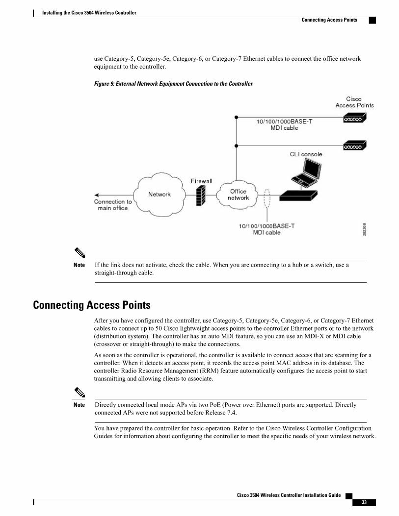
use Category-5, Category-5e, Category-6, or Category-7 Ethernet cables to connect the office networkequipment to the controller.
Figure 9: External Network Equipment Connection to the Controller
If the link does not activate, check the cable. When you are connecting to a hub or a switch, use astraight-through cable.
Note
Connecting Access PointsAfter you have configured the controller, use Category-5, Category-5e, Category-6, or Category-7 Ethernetcables to connect up to 50 Cisco lightweight access points to the controller Ethernet ports or to the network(distribution system). The controller has an auto MDI feature, so you can use an MDI-X or MDI cable(crossover or straight-through) to make the connections.
As soon as the controller is operational, the controller is available to connect access that are scanning for acontroller. When it detects an access point, it records the access point MAC address in its database. Thecontroller Radio Resource Management (RRM) feature automatically configures the access point to starttransmitting and allowing clients to associate.
Directly connected local mode APs via two PoE (Power over Ethernet) ports are supported. Directlyconnected APs were not supported before Release 7.4.
Note
You have prepared the controller for basic operation. Refer to the Cisco Wireless Controller ConfigurationGuides for information about configuring the controller to meet the specific needs of your wireless network.
Cisco 3504 Wireless Controller Installation Guide 33
Installing the Cisco 3504 Wireless ControllerConnecting Access Points
Troubleshooting the ControllerThis section contains the following topics:
• Checking the Controller LEDs, on page 34
• Using the Reset Button, on page 34
Checking the Controller LEDs
If the controller is not working properly, check the LEDs on the front panel of the unit. You can use the LEDindications to quickly assess the status of the unit. See Front Panel LEDs: Definitions of States, on page 5for a description of the front panel LEDs.
The installation is complete. Refer to the CiscoWireless Controller Configuration Guide for more informationabout configuring your controller.
Using the Reset Button
The Reset button on the front panel of the controller becomes active after the controller boots. To reset thecontroller using the Reset button, follow these steps:
1 Connect a PC to the controller console point.
2 Press and hold the Reset button for at least 3 seconds using a pointed object.
3 After the controller reboots, enter your username and password at the prompts.
If you have configured the controller, it reboots and loads the configuration. If you have not configured thecontroller, the configuration wizard is displayed.
Cisco 3504 Wireless Controller Installation Guide34
Installing the Cisco 3504 Wireless ControllerTroubleshooting the Controller

A P P E N D I X AController Specifications
This appendix lists the technical specifications for the controller.
• Physical Specifications, page 35
• Environmental Specifications , page 35
• Power Specifications, page 36
Physical SpecificationsTable 6: Physical Specifications
SpecificationDescription
8.5 in. (215.9 mm)Width
9.5 in. (241.3 mm)Depth
1.73 in. (43.94 mm)Height
4.4 lbs (2 kg)Weight
Environmental SpecificationsTable 7: Environmental Specifications
SpecificationDescription
–4° F to 158° F (–20° C to 70° C)Storage Temperature
32° F to 104° F (0° C to 40° C)Operating Temperature
Cisco 3504 Wireless Controller Installation Guide 35

SpecificationDescription
0% to 95% RH non-condensingStorage Humidity
5% to 95% RH non-condensingOperating Humidity
Fan remains off at lower operating temperatures. Fan starts spinning if the ambient temperature is morethan 30° C (86° F) and also depending on internal chassis temperatures.
Note
Power SpecificationsTable 8: AC Power Supply Specifications
SpecificationDescription
Universal 100 to 240 VACAC input voltage
50 to 60 HzFrequency
115 W
This is calculated as follows:
• 60 W @54 VDC
• 55 W @12 VDC
Maximum output power
PWR-115W-AC=Adapter
Table 9: Heat Dissipation and Power Consumption Specifications
SpecificationDescription
47 WMaximum heat dissipation (without PoE)
48 WMaximum heat dissipation (with 2-ports .3at)
47 WMaximum power consumption (without PoE)
98 WMaximum power consumption (with 2-ports .3at)
Cisco 3504 Wireless Controller Installation Guide36
Controller SpecificationsPower Specifications