CIRRUS AIRPLANE MAINTENANCE MANUAL …CIRRUS AIRPLANE MAINTENANCE MANUAL MODEL SR22 27-20 Page 3...
34
CIRRUS AIRPLANE MAINTENANCE MANUAL MODEL SR22 27-20 Page 1 All EFFECTIVITY: RUDDER AND YAW TRIM SYSTEM 1. DESCRIPTION This section describes that portion of the flight control system which controls the position and movement of the rudder. Included are; rudder system rigging, rudder pedal assembly, cables, pulleys and bellcranks, rudder-aileron interconnect, and yaw trim system. Serials 0002 thru 0497: Rudder control motion is transferred by the rudder pedals to the forward pulley gang at the bottom of the center console. From the pulley gang, control motion is passed to a single cable system which is routed under the cabin floor to the rudder-aileron interconnect, through to the rudder/ele- vator pulley gang under the baggage floor, and finally to the rudder actuation pulley. The rudder actuation pulley drives a push/pull rod attached to the rudder bellcrank which is bolted directly to the rudder. The rud- der and elevator control system utilize separate actuation pulleys which mount to a shared pulley-gang bracket mounted inside the empennage. Each set of pulleys has a cable retainer to prevent fouling. Adjust- able control stops at the rudder actuation pulley limit control surface travel. Two springs attached to the rudder pedal assembly and firewall provide rudder system interconnection and determine system cable tension. Serials 0498 & subs: Rudder control motion is transferred by the rudder pedals to the forward pulley gang at the bottom of the center console. From the pulley gang, control motion is transferred to a single cable system which is routed under the cabin floor to the rudder-aileron interconnect (Serials 0498 thru 2437), through to the rudder/elevator pulley gang under the baggage floor, and finally to the rudder empennage bellcrank. The rudder empennage bellcrank drives a push/pull rod attached to the aft rudder bellcrank which is bolted directly to the rudder. The rudder and elevator control system utilize separate bellcranks connected by a shared shaft mounted directly to the FS 306 bulkhead. Fixed control stops at the rudder empennage bellcrank limit control surface travel. Two springs attached to the rudder assembly and firewall provide rudder system interconnection and determine system cable tension. The yaw trim system employs either an electric trim tab (Serials 0004 thru 0168), or a ground-adjustable trim tab (Serials 0002, 0003, 0169 & subs). Neutral rudder position is held by a ground-adjustable spring cartridge which bolts to the left rudder pedal torque tube and center console assembly. The cartridge is a captured compression spring that provides a centering force regardless of the direction of control surface deflection. 15 Apr 2007
Transcript of CIRRUS AIRPLANE MAINTENANCE MANUAL …CIRRUS AIRPLANE MAINTENANCE MANUAL MODEL SR22 27-20 Page 3...

C I R R U S A I R P L A N E M A I N T E N A N C E M A N U A L M O D E L S R 2 2
EFFECTIVITY:
RUDDER AND YAW TRIM SYSTEM
1. DESCRIPTION
This section describes that portion of the flight control system which controls the position and movement of the rudder. Included are; rudder system rigging, rudder pedal assembly, cables, pulleys and bellcranks, rudder-aileron interconnect, and yaw trim system.
Serials 0002 thru 0497: Rudder control motion is transferred by the rudder pedals to the forward pulley gang at the bottom of the center console. From the pulley gang, control motion is passed to a single cable system which is routed under the cabin floor to the rudder-aileron interconnect, through to the rudder/ele-vator pulley gang under the baggage floor, and finally to the rudder actuation pulley. The rudder actuation pulley drives a push/pull rod attached to the rudder bellcrank which is bolted directly to the rudder. The rud-der and elevator control system utilize separate actuation pulleys which mount to a shared pulley-gang bracket mounted inside the empennage. Each set of pulleys has a cable retainer to prevent fouling. Adjust-able control stops at the rudder actuation pulley limit control surface travel. Two springs attached to the rudder pedal assembly and firewall provide rudder system interconnection and determine system cable tension.
Serials 0498 & subs: Rudder control motion is transferred by the rudder pedals to the forward pulley gang at the bottom of the center console. From the pulley gang, control motion is transferred to a single cable system which is routed under the cabin floor to the rudder-aileron interconnect (Serials 0498 thru 2437), through to the rudder/elevator pulley gang under the baggage floor, and finally to the rudder empennage bellcrank. The rudder empennage bellcrank drives a push/pull rod attached to the aft rudder bellcrank which is bolted directly to the rudder. The rudder and elevator control system utilize separate bellcranks connected by a shared shaft mounted directly to the FS 306 bulkhead. Fixed control stops at the rudder empennage bellcrank limit control surface travel. Two springs attached to the rudder assembly and firewall provide rudder system interconnection and determine system cable tension.
The yaw trim system employs either an electric trim tab (Serials 0004 thru 0168), or a ground-adjustable trim tab (Serials 0002, 0003, 0169 & subs). Neutral rudder position is held by a ground-adjustable spring cartridge which bolts to the left rudder pedal torque tube and center console assembly. The cartridge is a captured compression spring that provides a centering force regardless of the direction of control surface deflection.
27-20All
Page 115 Apr 2007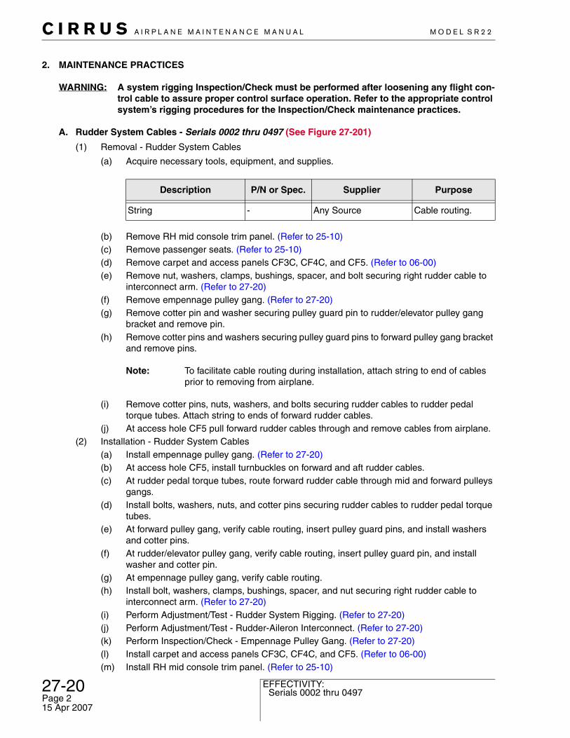
27-20 Serials 0002 thru 0497
C I R R U S A I R P L A N E M A I N T E N A N C E M A N U A L M O D E L S R 2 2
Page 215 Apr 2007
EFFECTIVITY:
2. MAINTENANCE PRACTICES
WARNING: A system rigging Inspection/Check must be performed after loosening any flight con-trol cable to assure proper control surface operation. Refer to the appropriate control system’s rigging procedures for the Inspection/Check maintenance practices.
A. Rudder System Cables - Serials 0002 thru 0497 (See Figure 27-201)
(1) Removal - Rudder System Cables
(a) Acquire necessary tools, equipment, and supplies.
(b) Remove RH mid console trim panel. (Refer to 25-10)(c) Remove passenger seats. (Refer to 25-10)(d) Remove carpet and access panels CF3C, CF4C, and CF5. (Refer to 06-00)(e) Remove nut, washers, clamps, bushings, spacer, and bolt securing right rudder cable to
interconnect arm. (Refer to 27-20)(f) Remove empennage pulley gang. (Refer to 27-20)(g) Remove cotter pin and washer securing pulley guard pin to rudder/elevator pulley gang
bracket and remove pin.(h) Remove cotter pins and washers securing pulley guard pins to forward pulley gang bracket
and remove pins.
Note: To facilitate cable routing during installation, attach string to end of cables prior to removing from airplane.
(i) Remove cotter pins, nuts, washers, and bolts securing rudder cables to rudder pedal torque tubes. Attach string to ends of forward rudder cables.
(j) At access hole CF5 pull forward rudder cables through and remove cables from airplane.(2) Installation - Rudder System Cables
(a) Install empennage pulley gang. (Refer to 27-20)(b) At access hole CF5, install turnbuckles on forward and aft rudder cables.(c) At rudder pedal torque tubes, route forward rudder cable through mid and forward pulleys
gangs.(d) Install bolts, washers, nuts, and cotter pins securing rudder cables to rudder pedal torque
tubes.(e) At forward pulley gang, verify cable routing, insert pulley guard pins, and install washers
and cotter pins.(f) At rudder/elevator pulley gang, verify cable routing, insert pulley guard pin, and install
washer and cotter pin.(g) At empennage pulley gang, verify cable routing.(h) Install bolt, washers, clamps, bushings, spacer, and nut securing right rudder cable to
interconnect arm. (Refer to 27-20)(i) Perform Adjustment/Test - Rudder System Rigging. (Refer to 27-20)(j) Perform Adjustment/Test - Rudder-Aileron Interconnect. (Refer to 27-20)(k) Perform Inspection/Check - Empennage Pulley Gang. (Refer to 27-20)(l) Install carpet and access panels CF3C, CF4C, and CF5. (Refer to 06-00)(m) Install RH mid console trim panel. (Refer to 25-10)
Description P/N or Spec. Supplier Purpose
String - Any Source Cable routing.

C I R R U S A I R P L A N E M A I N T E N A N C E M A N U A L M O D E L S R 2 2
EFFECTIVITY:
(n) Install passenger seats. (Refer to 25-10)(3) Adjustment/Test - Rudder System Rigging (See Figure 27-204)
Note: All control surface cable tensions should be rigged at an ambient temperature of 70°. Allow temperature to stabilize for a period of four hours before setting cable tensions.
(a) Acquire necessary tools, equipment, and supplies.
(b) Remove baggage compartment carpet and access panel CF5. (Refer to 06-00)
Note: Prior to removing turnbuckles, position spacer block between rudder pedals and firewall to support spring tension.
(c) Loosen rudder system turnbuckles so all cable tension is removed.(d) Remove access panels LE1, LE2 and RE2. (Refer to 06-00)(e) Insert lock-out pin at rudder actuation pulley in empennage.(f) Set Rudder Pedal Neutral Position.
1 Position rudder pedal pivot tubes so both left and right pedals are centered directly over gap between forward and aft torque tubes within 0.10 inch (2.54 mm). (See Figure 27-204)
2 At LH outboard rudder pedal, wedge spacer block between rudder pedal tube and firewall.
3 Tighten LH cable turnbuckle until spacer block falls away from pedal, indicating LH rudder pedals are in neutral position. Remove spacer block from airplane.
4 Repeat procedure on RH side.(g) Adjust rudder-to-vertical stabilizer alignment such that the rudder horn aligns with the ver-
tical stabilizer with no more than 0.1 inch (0.25 cm) misalignment.1 To move rudder trailing edge right, lengthen push/pull rod removing bolt securing
rod end to aft rudder bellcrank, loosening jam nut and turning rod end counterclock-wise.
2 Shorten push/pull rod for opposite results.(h) Remove lock-out pin from rudder actuation pulley in empennage.
WARNING: Applying right rudder should deflect rudder trailing edge to the right. If this is not true, system is improperly rigged. The system MUST BE RIGGED CORRECTLY. Check for crossed or wrapped cables.
(i) Verify application of right rudder deflects rudder trailing edge to the right.(j) Determine rudder travel.
1 With full left rudder applied, verify rudder deflection angle is equal to 20 ±1° by ensuring distance between chord line of vertical stabilizer and chord line of the deflected rudder horn is equal to 5.71 ±0.30 inches (14.5 ±0.76 cm). Adjust stop screws at empennage rudder actuation pulley if necessary.
2 Repeat procedure for right rudder travel.
Description P/N or Spec. Supplier Purpose
7 3/8” x 2” Wood Block - Any Source Spacer for holding neutral rudder position.
27-20Serials 0002 thru 0497
Page 315 Apr 2007
27-20 Serials 0002 thru 0497
C I R R U S A I R P L A N E M A I N T E N A N C E M A N U A L M O D E L S R 2 2
Page 415 Apr 2007
EFFECTIVITY:
3 Ensure that rudder actuation pulley stops limit rudder travel and not yaw trim car-tridge.
(k) Verify trim cartridge minimum rod end thread engagement of 0.312 inch (0.79 cm). Tighten jam nuts.
(l) Perform Inspection/Check - Yaw Trim Cartridge.(Refer to 27-20)(m) Install access panels LE1, LE2 and RE2. (Refer to 06-00)
(4) Inspection/Check - Rudder System Rigging
(a) Acquire necessary tools, equipment, and supplies.
(b) Perform Inspection/Check - Rudder Gap and Overlap. (Refer to 55-40)(c) Verify rudder neutral position remains at 0 ±1° with rudder pedals in neutral position.(d) Verify 20° rudder deflection angle. (Refer to 27-20)(e) Perform Inspection/Check - Rudder-Aileron Interconnect. (Refer to 27-20)(f) Verify minimum rod end thread engagement of 0.312 inch (0.79 cm).(g) Verify proper installation of safety wires and cotter pins on all fasteners and engagement
of all jam nuts throughout entire rudder control system.
Description P/N or Spec. Supplier Purpose
Scale6.0 inches (15.24 cm)
- Any Source Rudder rigging.
C I R R U S A I R P L A N E M A I N T E N A N C E M A N U A L M O D E L S R 2 2
EFFECTIVITY:
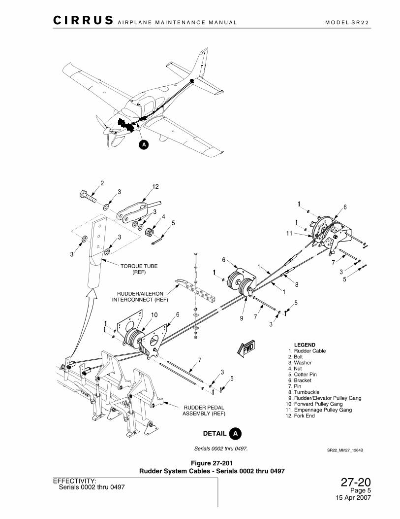
Figure 27-201Rudder System Cables - Serials 0002 thru 0497
Serials 0002 thru 0497. SR22_MM27_1364B
2
TORQUE TUBE(REF) 3
5
7
6
8
1
1
5
379
6
53
7
10 6
RUDDER PEDALASSEMBLY (REF)
RUDDER/AILERONINTERCONNECT (REF)
3
3
54
3
123
LEGEND 1. Rudder Cable 2. Bolt 3. Washer 4. Nut 5. Cotter Pin 6. Bracket 7. Pin 8. Turnbuckle 9. Rudder/Elevator Pulley Gang10. Forward Pulley Gang11. Empennage Pulley Gang12. Fork End
11
27-20Serials 0002 thru 0497
Page 515 Apr 2007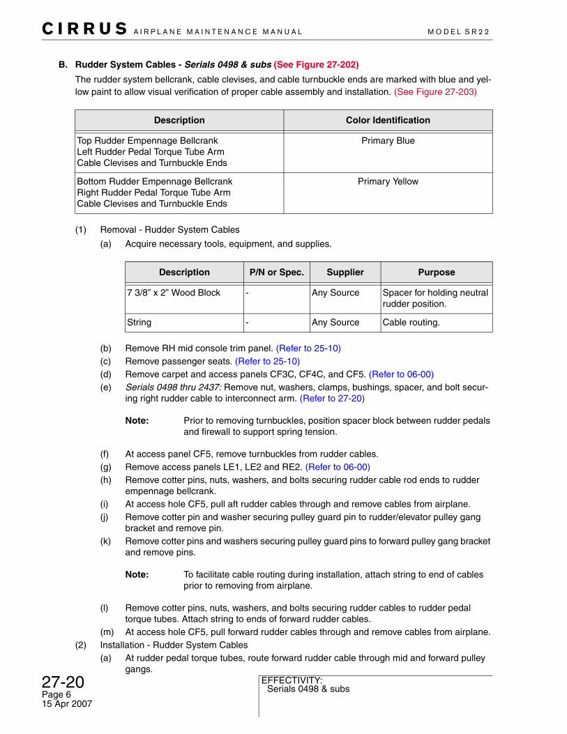
27-20 Serials 0498 & subs
C I R R U S A I R P L A N E M A I N T E N A N C E M A N U A L M O D E L S R 2 2
Page 615 Apr 2007
EFFECTIVITY:
B. Rudder System Cables - Serials 0498 & subs (See Figure 27-202)
The rudder system bellcrank, cable clevises, and cable turnbuckle ends are marked with blue and yel-low paint to allow visual verification of proper cable assembly and installation. (See Figure 27-203)
(1) Removal - Rudder System Cables
(a) Acquire necessary tools, equipment, and supplies.
(b) Remove RH mid console trim panel. (Refer to 25-10)(c) Remove passenger seats. (Refer to 25-10)(d) Remove carpet and access panels CF3C, CF4C, and CF5. (Refer to 06-00)(e) Serials 0498 thru 2437: Remove nut, washers, clamps, bushings, spacer, and bolt secur-
ing right rudder cable to interconnect arm. (Refer to 27-20)
Note: Prior to removing turnbuckles, position spacer block between rudder pedals and firewall to support spring tension.
(f) At access panel CF5, remove turnbuckles from rudder cables.(g) Remove access panels LE1, LE2 and RE2. (Refer to 06-00)(h) Remove cotter pins, nuts, washers, and bolts securing rudder cable rod ends to rudder
empennage bellcrank.(i) At access hole CF5, pull aft rudder cables through and remove cables from airplane.(j) Remove cotter pin and washer securing pulley guard pin to rudder/elevator pulley gang
bracket and remove pin.(k) Remove cotter pins and washers securing pulley guard pins to forward pulley gang bracket
and remove pins.
Note: To facilitate cable routing during installation, attach string to end of cables prior to removing from airplane.
(l) Remove cotter pins, nuts, washers, and bolts securing rudder cables to rudder pedal torque tubes. Attach string to ends of forward rudder cables.
(m) At access hole CF5, pull forward rudder cables through and remove cables from airplane.(2) Installation - Rudder System Cables
(a) At rudder pedal torque tubes, route forward rudder cable through mid and forward pulley gangs.
Description Color Identification
Top Rudder Empennage BellcrankLeft Rudder Pedal Torque Tube ArmCable Clevises and Turnbuckle Ends
Primary Blue
Bottom Rudder Empennage BellcrankRight Rudder Pedal Torque Tube ArmCable Clevises and Turnbuckle Ends
Primary Yellow
Description P/N or Spec. Supplier Purpose
7 3/8” x 2” Wood Block - Any Source Spacer for holding neutral rudder position.
String - Any Source Cable routing.
C I R R U S A I R P L A N E M A I N T E N A N C E M A N U A L M O D E L S R 2 2
EFFECTIVITY:
(b) Install bolts, washers, nuts and cotter pins securing rudder cables to rudder pedal torque tubes.
(c) At forward pulley gang, verify cable routing, insert pulley guard pins, and install washers and cotter pins.
(d) At rudder/elevator pulley gang, verify cable routing, insert pulley guard pin, and install washer and cotter pin.
(e) Route aft rudder cable from access hole CF5 to rudder empennage bellcrank. Install bolts, washers, nuts, and cotter pins securing rudder cable rod end to rudder empennage bellcrank.
(f) At access hole CF5, install turnbuckles on forward and aft rudder cables.(g) Serials 0498 thru 2437: Install bolt, washers, clamps, bushings, spacer, and nut securing
right rudder cable to interconnect arm. (Refer to 27-20)(h) Perform Adjustment/Test - Rudder System Rigging. (Refer to 27-20)(i) Serials 0498 thru 2437: Perform Adjustment/Test - Rudder-Aileron Interconnect. (Refer to
27-20)(j) Perform Inspection/Check - Empennage Bellcranks. (Refer to 27-20)(k) Install carpet and access panels CF3C, CF4C, and CF5. (Refer to 06-00)(l) Install RH mid console trim panel. (Refer to 25-10)(m) Install passenger seats. (Refer to 25-10)
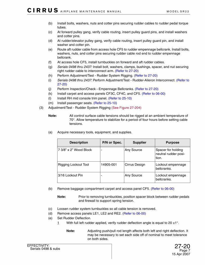
(3) Adjustment/Test - Rudder System Rigging (See Figure 27-204)
Note: All control surface cable tensions should be rigged at an ambient temperature of 70°. Allow temperature to stabilize for a period of four hours before setting cable tensions.
(a) Acquire necessary tools, equipment, and supplies.
(b) Remove baggage compartment carpet and access panel CF5. (Refer to 06-00)
Note: Prior to removing turnbuckles, position spacer block between rudder pedals and firewall to support spring tension.
(c) Loosen rudder system turnbuckles so all cable tension is removed.(d) Remove access panels LE1, LE2 and RE2. (Refer to 06-00)(e) Set Rudder Deflection.
1 With full left rudder applied, verify rudder deflection angle is equal to 20 ±1°.
Note: Adjusting push/pull rod length affects both left and right deflection. It may be necessary to set each side off of nominal to meet tolerance on both sides.
Description P/N or Spec. Supplier Purpose
7 3/8” x 2” Wood Block - Any Source Spacer for holding neutral rudder posi-tion.
Rigging Lockout Tool 14905-001 Cirrus Design Lockout empennage bellcranks.
3/16 Lockout Pin - Any Source Lockout empennage bellcranks.
27-20Serials 0498 & subs
Page 715 Apr 2007
27-20 Serials 0498 & subs
C I R R U S A I R P L A N E M A I N T E N A N C E M A N U A L M O D E L S R 2 2
Page 815 Apr 2007
EFFECTIVITY:
2 To increase deflection angle, lengthen push/pull rod by removing bolt securing rod end to aft rudder bellcrank, loosening jam nut, and turning rod end counterclock-wise.
3 Shorten push/pull rod for opposite results.4 Repeat procedure for right rudder travel.5 Distance between chord line of vertical stabilizer and chord line of left deflected rud-
der horn and distance between chord line of vertical stabilizer and chord line of right deflected rudder horn must be within 0.30 inches (7.62 mm).
(f) Using rigging lock-out tool and pin, lock-out rudder empennage bellcrank.(g) Set Rudder Pedal Neutral Position.
1 Serials 0498 thru 0820: Position rudder pedal pivot tubes so both left and right ped-als are centered directly over gap between forward and aft torque tubes within 0.10 inch (2.54 mm). (See Figure 27-204)
2 Serials 0821 & subs: Position rudder pedal pivot tubes so both left and right pedals are 0.5 ±0.1 inch (12.7 ±2.54 mm) aft of gap between forward and aft torque tubes. (See Figure 27-204)
3 At LH outboard rudder pedal, wedge spacer block between rudder pedal tube and firewall.
4 Tighten LH cable turnbuckle until spacer block falls away from pedal, indicating LH rudder pedals are in neutral position. Remove spacer block from airplane.
5 Repeat procedure on RH side.(h) Remove rigging lock-out tool and pin from rudder empennage bellcrank.
WARNING: Applying right rudder should deflect rudder trailing edge to the right. If this is not true, system is improperly rigged. The system MUST BE RIGGED CORRECTLY. Check for crossed or wrapped cables and verify color identification is correct.
(i) Verify application of right rudder deflects rudder trailing edge to the right.(j) Verify trim cartridge minimum rod end thread engagement of 0.313 inch (0.79 cm).
Tighten jam nuts.(k) Perform Inspection/Check - Yaw Trim Cartridge. (Refer to 27-20)(l) Install access panels LE1, LE2 and RE2. (Refer to 06-00)
(4) Inspection/Check - Rudder System Rigging
(a) Acquire necessary tools, equipment, and supplies.
(b) Perform Inspection/Check - Rudder Gap and Overlap. (Refer to 55-40)(c) Verify rudder neutral position remains at 0 ±1° with rudder pedals in neutral position.(d) Verify 20° rudder deflection angle. (Refer to 27-20)(e) Serials 0498 thru 2437: Perform Inspection/Check - Rudder-Aileron Interconnect. (Refer to
27-20)(f) Verify minimum rod end thread engagement of 0.313 inch (0.79 cm).(g) Verify proper installation of safety wires and cotter pins on all fasteners and engagement
of all jam nuts throughout entire rudder control system.
Description P/N or Spec. Supplier Purpose
Scale6.0 inches (15.24 cm)
- Any Source Rudder rigging.

C I R R U S A I R P L A N E M A I N T E N A N C E M A N U A L M O D E L S R 2 2
EFFECTIVITY:
Figure 27-202Rudder System Cables - Serials 0498 & subs
RUDDER/AILERONINTERCONNECT (REF)
6
53
7
10
1
BH306(REF)
5
11
4
3
2
SR22_MM27_1631A
2
TORQUE TUBE(REF)
8
1
1
5
379
6
RUDDER PEDALASSEMBLY (REF)
3
3
54
3
123
LEGEND 1. Rudder Cable 2. Bolt 3. Washer 4. Nut 5. Cotter Pin 6. Bracket 7. Pin 8. Turnbuckle 9. Rudder/Elevator Pulley Gang10. Forward Pulley Gang11. Rudder Empennage Bellcrank12. Fork End
Serials 0002 thru 2333, 2335thru 2419, 2421 thru 2437.
27-20Serials 0498 & subs
Page 915 Apr 2007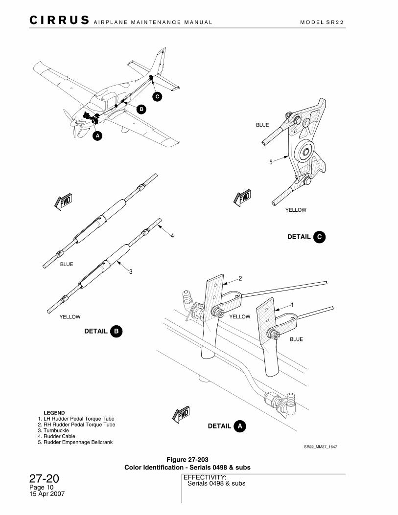
27-20 Serials 0498 & subs
C I R R U S A I R P L A N E M A I N T E N A N C E M A N U A L M O D E L S R 2 2
Page 1015 Apr 2007
EFFECTIVITY:
Figure 27-203Color Identification - Serials 0498 & subs
SR22_MM27_1647
YELLOW
BLUE
YELLOW
BLUE
YELLOW
BLUE
LEGEND 1. LH Rudder Pedal Torque Tube 2. RH Rudder Pedal Torque Tube 3. Turnbuckle 4. Rudder Cable 5. Rudder Empennage Bellcrank
5
3
4
2
1

C I R R U S A I R P L A N E M A I N T E N A N C E M A N U A L M O D E L S R 2 2
EFFECTIVITY:
Figure 27-204Rudder Rigging
0.5 ± 0.1 inch(12.7 ±2.5 mm)
0.03 ±0.06 inch(0.76 ±1.52 mm)
NOTE
Position rudder pedal pivot tubes so both the left and right pedals are centered directly ±0.1 inch (±2.5 mm) over gap between forward and aft torque tubes.
With bellcrank lock-out tool in place, verify distance between center of lock-out hole and forward surface of 306 bulkhead is 0.03 ±0.06 inch (0.76 ±1.52 mm).
Position rudder pedal pivot tubes so both the left and right pedals are 0.5 ±0.1 inch (12.7 ±2.5 mm) aft of gap between forward and aft torque tubes.
SR22_MM27_1637C
LEGEND1. Rudder Pedal2. Pivot Tube3. Torque Tube4. Rudder Empennage Bellcrank5. Bellcrank Lock-out Tool6. Lock-out Pin
1
2
3
3 4
BULKHEAD 306(REF)
LOCK-OUT HOLE(REF)
5
Serials 0002 thru 0820.
Serials 0498 & subs.
6
Serials 0821 & subs.
1
2
3
3
27-20All
Page 1115 Apr 2007
27-20 All
C I R R U S A I R P L A N E M A I N T E N A N C E M A N U A L M O D E L S R 2 2
Page 1215 Apr 2007
EFFECTIVITY:
C. Rudder Pedal Assembly (See Figure 27-205)
(1) Removal - Rudder Pedal Assembly(a) Remove pilot and co-pilot seats. (Refer to 25-10)(b) Remove left mid console circuit breaker trim panel. (Refer to 25-10)(c) Remove carpet and access panel CF5 from baggage compartment floor. (Refer to 06-00)(d) Identify and loosen rudder cable tension via turnbuckle.(e) Remove yaw trim cartridge. (Refer to 27-20)(f) Remove cotter pin, nut, washers, and bolt securing cable fork ends to torque tube actua-
tion arm.(g) Disconnect springs from firewall and torque tube actuation arms.(h) Remove cotter pins, washers, and clevis pins from upper connection at rudder pedals of
each master cylinder.(i) Remove cotter pin and washers from rudder pedal pivot tube.(j) Slide rudder pedal pivot tube from bearing.(k) Detach rudder pedal from torque tube weldment.(l) Disconnect brake lines at torque tube fittings. Cap brake lines and fittings.(m) Remove carpet and forward access panels CF1R and CF1L to gain access to torque tube
mounting nuts. (Refer to 06-00)(n) Remove cotter pin, nut, washers, and bolt securing rudder pedal assembly and bracket to
floor.(o) Remove torque tube assembly from airplane.
(2) Installation - Rudder Pedal Assembly(a) Align torque tube assembly and bracket over mounting holes on airplane floor and install
bolts, washers, nuts, and cotter pins securing torque tube assembly to airplane floor.(b) Perform Inspection/Check - Torque Tube Gap Tolerance. (Refer to 27-20)(c) Install forward access panels CF1R and CF1L. (Refer to 06-00)(d) Install carpet. (Refer to 25-10)(e) Connect brake lines at torque tube fittings.(f) Align rudder pedal on torque tube weldment, insert rudder pedal pivot tube, and install
washer and cotter pin.(g) Install clevis pin, washers, and cotter pin securing rudder pedal to upper connection on
master cylinder.(h) Connect springs to firewall and torque tube actuation arms.(i) Install bolt, washers, nut and cotter pin securing cable fork ends to torque tube actuation
arms.(j) Install yaw trim cartridge. (Refer to 27-20)(k) Perform Inspection/Check - Rudder Pedal Assembly. (Refer to 27-20)(l) Install left mid console circuit breaker trim panel. (Refer to 25-10)(m) Install pilot and co-pilot seats. (Refer to 25-10)(n) Bleed brake system. (Refer to 32-42)
(3) Inspection/Check - Torque Tube Gap Tolerance
CAUTION: Gap between flange on bushing and rudder pedal torque tube must not exceed 0.06 inch (1.5 mm). Prior to measuring gap, push torque tube assembly to oppos-ing side.
(a) Push torque tube assembly to opposite side of where measurement is being made and place feeler gauge between bushing and torque tube to verify gap is within tolerance throughout full range of pedal motion.

C I R R U S A I R P L A N E M A I N T E N A N C E M A N U A L M O D E L S R 2 2
EFFECTIVITY:
(b) If necessary, adjust Torque Tube Gap Tolerance:
1 Acquire necessary tools, equipment, and supplies.
Note: To maintain correct rudder system cable tension remove one rudder pedal bracket at a time, always leaving one end of torque tube attached to cabin floor.
2 Remove nuts, washers, and bolts securing bracket to floor.3 Remove bracket and bushing from end of torque tube.4 Remove nut, washer, and bolt securing bushing to bracket.
Note: Up to two additional washers may be added on one end of torque tube to obtain gap tolerance.
5 Add washer(s) between bracket and bushing as required to obtain gap tolerance. 6 Install bolt, washer, and nut securing bushing to bracket. Verify bolt clamps bushing
tight against bracket.7 Coat bushing with oil and insert bushing assembly into torque tube.8 Install bolts, washers, and nuts securing bracket to airplane floor.9 Verify gap between bushing and torque tube does not exceed 0.06 inch (1.5 mm). If
necessary, re-adjust Torque Tube Gap Tolerance.(4) Inspection/Check - Rudder Pedal Assembly
(a) Verify torque tube bushing attach bolt torque is 50 - 70 in-lb (5.6 - 7.9 Nm)(b) Verify positive rudder pedal clearance through full range of pedal motion from brake lines
and any other console structure or systems.
Description P/N or Spec. Supplier Purpose
Washer NAS1149F0463P Any Source Obtain gap tolerance.
27-20All
Page 1315 Apr 2007
27-20 All
C I R R U S A I R P L A N E M A I N T E N A N C E M A N U A L M O D E L S R 2 2
Page 1415 Apr 2007
EFFECTIVITY:
D. Rudder Pedal Bracket (See Figure 27-205)
During the removal and installation of the rudder pedal brackets, it is important to maintain the correct rudder system cable tension. Remove one bracket at a time, always leaving one end of torque tube firmly attached to cabin floor.
(1) Removal - Rudder Pedal Bracket(a) Remove pilot and co-pilot seats. (Refer to 25-10)(b) Remove carpet and forward access panels CF1R and CF1L to gain access to rudder
pedal bracket mounting nuts. (Refer to 06-00)(c) Remove nuts, washers, and bolts securing bracket to floor.(d) Remove bracket and bushing from end of torque tube.(e) Remove nut, washer, and bolt securing bushing to bracket.
(2) Installation - Rudder Pedal Bracket(a) Install nut, washer, and bolt securing bushing to bracket. Verify bolt clamps bushing tight
against bracket.(b) Coat bushing with oil and insert bushing assembly into torque tube.(c) Install bolts, washers, and nuts securing bracket to airplane floor(d) Perform Inspection/Check - Torque Tube Gap Tolerance. (Refer to 27-20)(e) Install forward access panels CF1R and CF1L and carpet. (Refer to 06-00)(f) Install pilot and co-pilot seats. (Refer to 25-10)

C I R R U S A I R P L A N E M A I N T E N A N C E M A N U A L M O D E L S R 2 2
EFFECTIVITY:
Figure 27-205Rudder Pedal Installation
2
121
2
1010
SR22_MM27_1365D
17
2122
217
15
12 16
12
28
18
21
1920
214
23
18
7
1
26
813
3
22
9
1
1011
122
912
22
12
1
5
2
3
3
41 2
24
19. Spring 20. Eye Bolt21. Brake Line22. Jam Nut23. Fitting24. Master Cylinder
10. Spacer 11. Cartridge Spacer12. Bolt13. Yaw Trim Cartridge14. Nut15. Torque Tube Bracket16. Torque Tube Bushing17. Left Torque Tube18. Right Torque Tube
LEGEND1. Cotter Pin2. Washer3. Bushing4. Rudder Pedal5. Rudder Pedal Pin6. Weldment Tube7. Clevis8. Clevis Pin9. Castellated Nut
FIREWALL(REF)
CONSOLE(REF)
NOTES
Measure gap between flange on bushingand end of Rudder Pedal Torque Tube Bracket. Maximum gap tolerance is 0.06 inch (1.5 mm).
Up to two additional washers may be installed on one end of torque tube to obtain gap tolerance.
1422
2
14
27-20All
Page 1515 Apr 2007
27-20 All
C I R R U S A I R P L A N E M A I N T E N A N C E M A N U A L M O D E L S R 2 2
Page 1615 Apr 2007
EFFECTIVITY:
E. Forward Pulley Gang (See Figure 27-106) (See Figure 27-107)
The forward pulley gang is used to route the aileron, rudder, and elevator system control cables. Main-tenance practices pertinent to the forward pulley gang are covered under the Aileron and Roll Trim System. (Refer to 27-10)
F. Rudder/Elevator Pulley Gang (See Figure 27-206)
(1) Removal - Rudder/Elevator Pulley Gang
(a) Acquire necessary tools, equipment, and supplies.
(b) Remove carpet and access panel CF5 from baggage compartment floor. (Refer to 06-00)
Note: Prior to removing turnbuckles, position spacer block between rudder pedals and firewall to support spring tension.
(c) Identify and loosen rudder and elevator cable tension via turnbuckle.(d) Remove cotter pin, nut, washers, spacers, and bolt securing pulleys to rudder/elevator pul-
ley gang bracket and remove components from airplane.(2) Installation - Rudder/Elevator Pulley Gang
(a) Position and install bolt, spacers, washers, nut, and cotter pin securing pulleys to rudder/elevator pulley gang bracket.
(b) Rig rudder system and perform Adjustment/Test - Rudder System Rigging. (Refer to 27-20), (Refer to 27-20)
(c) Rig elevator system and perform Adjustment/Test - Elevator System Rigging. (Refer to 27-30), (Refer to 27-30)
(d) Install fuselage floor access panel CF5 and carpet. (Refer to 06-00)
Description P/N or Spec. Supplier Purpose
7 3/8” x 2” Wood Block - Any Source Spacer for holding neutral rudder posi-tion.

C I R R U S A I R P L A N E M A I N T E N A N C E M A N U A L M O D E L S R 2 2
EFFECTIVITY:
G. Empennage Pulley Gang - Serials 0002 thru 0497 (See Figure 27-207)
(1) Removal - Empennage Pulley Gang
(a) Acquire necessary tools, equipment, and supplies.
(b) Remove carpet and access panel CF5 from baggage compartment floor. (Refer to 06-00)
Note: Prior to removing turnbuckles, position spacer block between rudder pedals and firewall to support spring tension.
(c) At access panel CF5, remove turnbuckles from rudder and elevator cables.(d) Remove fuselage access panels RE1, RE2, LE1, and LE2. (Refer to 06-00)(e) Loosen jam nuts securing rudder and elevator push/pull rods to rudder and elevator actua-
tion pulleys.(f) Remove cotter pin, nut, washer, spacer, and bolt securing rudder push/pull rod to rudder
bellcrank.(g) Remove cotter pin, nut, washers, and bolt securing elevator push/pull rod to elevator
bellcrank.(h) Unscrew rudder push/pull rod from rod end attached to rudder actuation pulley and
remove from airplane.(i) Unscrew elevator push/pull rod from rod end attached to elevator actuation pulley and
remove from airplane.(j) Remove nut, washer, and screw securing support brace to empennage, loosen jam nut
securing support brace to pulley gang, and remove support brace from airplane.(k) Gain access to pulley gang mounting bracket through access hole in FS 306 bulkhead and
remove bolts securing pulley gang to bulkhead. Remove gang assembly from airplane.(l) Remove cotter pins and washers securing pulley guard pins to empennage pulley gang
bracket and remove pins.(m) Cut safety wire securing cables to actuation pulleys.(n) At access hole CF5, pull rudder and elevator cables through. Remove cables from air-
plane.(2) Installation - Empennage Pulley Gang
(a) Prior to empennage pulley gang installation, secure rudder and elevator cables to actua-tion pulleys with safety wire and insert pulley guard pins, install washers and cotter pins.
(b) Route rudder and elevator cables through access hole RE1 forward to access hole CF5.(c) Insert pulley gang into empennage and position gang assembly over holes in FS 306 bulk-
head. Install bolts securing pulley gang to bulkhead.(d) Screw rudder push/pull rod onto rod end attached to rudder actuation pulley and tighten
jam nut.(e) Screw elevator push/pull rod onto rod end attached to elevator actuation pulley and tighten
jam nut.(f) Install bolt, spacer, washer, nut, and cotter pin securing rudder push/pull rod to rudder
bellcrank.(g) Install bolt, washers, nut, and cotter pin securing elevator push/pull rod to elevator
bellcrank.
Description P/N or Spec. Supplier Purpose
7 3/8” x 2” Wood Block - Any Source Spacer for holding neutral rudder posi-tion.
27-20Serials 0002 thru 0497
Page 1715 Apr 2007
27-20 Serials 0002 thru 0497
C I R R U S A I R P L A N E M A I N T E N A N C E M A N U A L M O D E L S R 2 2
Page 1815 Apr 2007
EFFECTIVITY:
(h) Install screw, washer, and nut securing pulley gang support brace to empennage.(i) Install Rudder and Elevator Cables. (Refer to 27-20), (Refer to 27-30)
(3) Inspection/Check - Empennage Pulley Gang(a) Remove fuselage access panels RE1, RE2 LE1, and LE2. (Refer to 06-00)(b) Verify positive clearance of pulleys through full range of rudder and elevator movement.(c) Verify positive clearance between pitch trim cartridge and FS 306 bulkhead through full
range of elevator and trim motor operation.(d) Verify minimum rod end thread engagement of 0.312 inch (0.79 cm).(e) Verify proper safety wire and cotter pin installation on all fasteners.(f) Install fuselage access panels RE1, RE2 LE1, and LE2. (Refer to 06-00)

C I R R U S A I R P L A N E M A I N T E N A N C E M A N U A L M O D E L S R 2 2
EFFECTIVITY:
H. Empennage Bellcranks - Serials 0498 & subs (See Figure 27-208)
(1) Removal - Empennage Bellcranks(a) Remove carpet and access panel CF5 from baggage compartment floor. (Refer to 06-00)
Note: Prior to removing turnbuckles, position spacer block between rudder pedals and firewall to support spring tension.
(b) At access panel CF5, remove turnbuckles from rudder and elevator cables.(c) Remove fuselage access panels RE1, RE2, LE1, and LE2. (Refer to 06-00)(d) Loosen jam nuts securing rudder and elevator push/pull rods to rudder and elevator
empennage bellcranks.(e) Remove cotter pin, nut, washers, and bolt securing rudder push/pull rod to rudder
bellcrank.(f) Remove cotter pin, nut, washers, and bolt securing elevator push/pull rod to elevator
bellcrank.(g) Unscrew rudder push/pull rod from rod end attached to rudder empennage bellcrank and
remove from airplane.(h) Unscrew elevator push/pull rod from rod end attached to elevator empennage bellcrank
and remove from airplane.(i) Remove plug covering end of bulkhead shaft.(j) Remove bolt and washer securing bulkhead shaft to bulkhead.(k) Remove bulkhead shaft and bellcranks from airplane.(l) At access hole CF5, pull rudder and elevator cables through. Remove cables airplane.
(2) Installation - Empennage Bellcranks(a) Route rudder and elevator cables through access hole RE1 forward to access hole CF5.(b) Insert bellcranks into empennage and position bulkhead shaft through bulkhead and
bellcranks.
Note: Ensure bolt engages threaded insert to within 0.063 inch (1.6 mm) of flush with bulkhead surface or protrudes past bulkhead surface.
(c) Install bolt and washer securing bulkhead shaft to bulkhead.(d) Install plug covering end of bulkhead shaft.(e) Screw rudder push/pull rod onto rod end attached to rudder empennage bellcrank and
tighten jam nut.(f) Screw elevator push/pull rod onto rod end attached to elevator empennage bellcrank and
tighten jam nut.(g) Install bolt, spacer, washer, nut, and cotter pin securing rudder push/pull rod to rudder
bellcrank.(h) Install bolt, washers, nut, and cotter pin securing elevator push/pull rod to elevator
bellcrank.(i) Install Rudder and Elevator Cables. (Refer to 27-20), (Refer to 27-30)
(3) Inspection/Check - Empennage Bellcranks(a) Remove fuselage access panels RE1, RE2 LE1, and LE2. (Refer to 06-00)(b) Verify positive clearance of bellcranks through full range of rudder and elevator movement.(c) Verify positive clearance between pitch trim cartridge and vertical stabilizer bulkhead
through full range of elevator and trim motor operation.(d) Verify minimum rod end thread engagement of 0.313 inch (0.79 cm).(e) Verify proper safety wire and cotter pin installation on all fasteners.(f) Install fuselage access panels RE1, RE2 LE1, and LE2. (Refer to 06-00)
27-20Serials 0498 & subs
Page 1915 Apr 2007
27-20 All
C I R R U S A I R P L A N E M A I N T E N A N C E M A N U A L M O D E L S R 2 2
Page 2015 Apr 2007
EFFECTIVITY:
Figure 27-206Rudder/Elevator Pulley Gang
2
2
LEGEND 1. Cotter Pin 2. Washer 3. Castellated Nut 4. Spacer 5. Bolt 6. Pulley Bracket 7. Backing Plate 8. Pin 9. Pulley
SR22_MM27_1366
4
6
1
8
9
13
2 3
7
BULKHEADF.S. 186 (REF)
1
21
5

C I R R U S A I R P L A N E M A I N T E N A N C E M A N U A L M O D E L S R 2 2
EFFECTIVITY:
Figure 27-207Empennage Pulley Gang - Serials 0002 thru 0497 (Sheet 1 of 2)
52
ELEVATORHINGE (REF)
25
2
721 3 1
5
2RUDDERASSY (REF)
743
1
61
2
11
10
72
22
8
SR22_MM27_1367A
5
ELEVATOR BELL CRANK (REF)
23
72
2
9
31
6BULKHEADF.S. 306 (REF)
2
LEGEND 1. Cotter Pin 2. Washer 3. Castellated Nut 4. Spacer 5. Bolt 6. Nut 7. Rod End 8. Elevator Push/Pull Rod 9. Rudder Push/Pull Rod10. Support Brace11. Screw
5
Serials 0002 thru 0497.
27-20Serials 0002 thru 0497
Page 2115 Apr 2007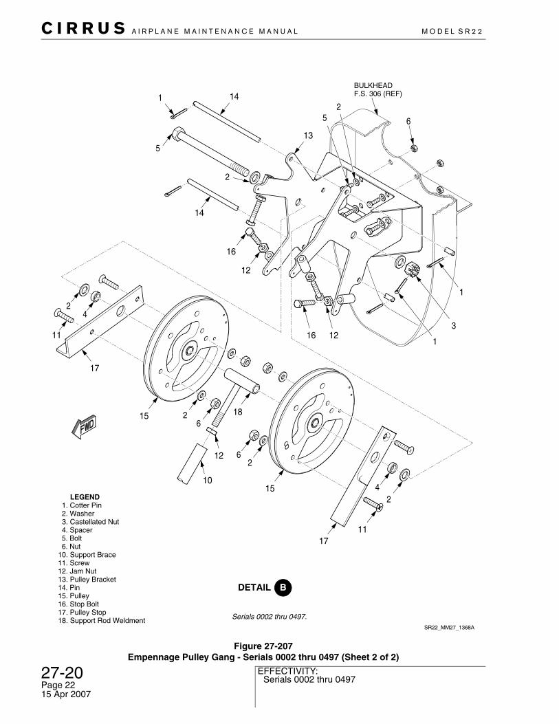
27-20 Serials 0002 thru 0497
C I R R U S A I R P L A N E M A I N T E N A N C E M A N U A L M O D E L S R 2 2
Page 2215 Apr 2007
EFFECTIVITY:
Figure 27-207Empennage Pulley Gang - Serials 0002 thru 0497 (Sheet 2 of 2)
SR22_MM27_1368A
5
13
BULKHEADF.S. 306 (REF)
1
3
1
2
16
2
1 14
15
2
12
415
26
18
12
10
5
17
4
11
17
6
16
12
LEGEND 1. Cotter Pin 2. Washer 3. Castellated Nut 4. Spacer 5. Bolt 6. Nut10. Support Brace11. Screw12. Jam Nut13. Pulley Bracket14. Pin15. Pulley16. Stop Bolt17. Pulley Stop18. Support Rod Weldment
11
26
2
14
Serials 0002 thru 0497.

C I R R U S A I R P L A N E M A I N T E N A N C E M A N U A L M O D E L S R 2 2
EFFECTIVITY:
Figure 27-208Empennage Bellcranks - Serials 0498 & subs
RUDDERASSY (REF)
SR22_MM27_1643
AFT ELEVATORBELLCRANK
(REF)
BULKHEADF.S. 306 (REF)
1
1
1
1
1
2
2
2
2
2
2
2
2
2
3
3
3
3
4
4
4
4
5
5
5
5
6
7
8
9
10
11
LEGEND 1. Bolt 2. Washer 3. Rod End 4. Castellated Nut 5. Cotter Pin 6. Rudder Bellcrank 7. Elevator Bellcrank 8. Elevator Push/Pull Rod 9. Rudder Push/Pull Rod10. Shaft11. Plug
27-20Serials 0498 & subs
Page 2315 Apr 2007
27-20 All
C I R R U S A I R P L A N E M A I N T E N A N C E M A N U A L M O D E L S R 2 2
Page 2415 Apr 2007
EFFECTIVITY:
I. Yaw Trim Cartridge (See Figure 27-205)
(1) Removal - Yaw Trim Cartridge (a) Remove left mid console circuit breaker trim. (Refer to 25-10)(b) Remove cotter pin, nut, washers, bushing, spacers, and bolt securing trim cartridge to
console bracket.(c) Remove cotter pin, nut, washers, and bolt securing trim cartridge push/pull rod to left
torque tube actuation arm and remove from airplane.(2) Installation - Yaw Trim Cartridge
(a) Install bolt, washers, nut, and cotter pin securing trim cartridge push/pull rod to left torque tube actuation arm.
(b) Install bolt, washers, bushing, spacers, nut, and cotter pin securing trim cartridge to con-sole bracket.
(c) Perform Inspection/Check - Yaw Trim Cartridge. (Refer to 27-20)(d) Install Left Mid Console Circuit Breaker Trim. (Refer to 25-10)
(3) Inspection/Check - Yaw Trim Cartridge(a) Verify correct rudder system rigging. (Refer to 27-20), (Refer to 27-20)(b) Verify yaw trim cartridge is adjusted to hold rudder in neutral position ±1°.(c) Verify positive clearance between trim cartridge and actuation pulley under full range of
trim motor positions.(d) Verify minimum rod end thread engagement of 0.312 inch (0.79 cm).(e) Verify proper installation of safety wires and cotter pins on all fasteners.

C I R R U S A I R P L A N E M A I N T E N A N C E M A N U A L M O D E L S R 2 2
EFFECTIVITY:
J. Yaw Trim Servo - Serials 0004 thru 0168 (See Figure 27-209)
(1) Removal - Yaw Trim Servo (a) Disconnect Pitch/Yaw Trim circuit breaker.(b) Remove composite rudder tip from bottom of rudder.(c) Disconnect yaw trim wire harness.(d) Disconnect ground wires.(e) Disassemble connector.(f) Disconnect cable ties securing wire harness to rudder.(g) Disconnect trim actuation arm from rudder trim tab assembly.(h) Remove rivets securing yaw trim servo to rudder and remove servo assembly from air-
plane.(2) Installation - Yaw Trim Servo
(a) Position yaw trim servo to rudder and secure with rivets.(b) Connect trim actuation arm to rudder trim tab assembly so that actuation arm extends
approximately 0.38 inch past nut.(c) Connect cable ties securing wire harness to rudder.(d) Assemble wire harness connector.(e) Connect ground wires.(f) Connect yaw trim servo wire harness connector.(g) Install composite rudder tip to bottom of rudder.(h) Reset Pitch/Yaw Trim circuit breaker.
27-20Serials 0004 thru 0168
Page 2515 Apr 2007
27-20 Serials 0004 thru 0168
C I R R U S A I R P L A N E M A I N T E N A N C E M A N U A L M O D E L S R 2 2
Page 2615 Apr 2007
EFFECTIVITY:
K. Yaw Trim Gage - Serials 0004 thru 0168 (See Figure 27-209)
(1) Removal - Yaw Trim Gage(a) Disconnect Pitch/Yaw Trim circuit breaker.(b) Remove screws securing gage to center console.(c) Disconnect yaw trim gage connector and remove from airplane.
(2) Installation - Yaw Trim Gage(a) Connect yaw trim gage connector.(b) Install screws securing yaw trim gage to center console.(c) Reset Pitch/Yaw Trim circuit breaker.

C I R R U S A I R P L A N E M A I N T E N A N C E M A N U A L M O D E L S R 2 2
EFFECTIVITY:
L. Rudder Trim Tab - Serials 0002, 0003, 0169 & subs
Yaw trim adjustment is ground adjustable only and is achieved by changing the deflection angle of the rudder trim tab. For maintenance practices pertinent to the rudder trim tab, see Rudder. (Refer to 55-40)
27-20Serials 0002, 0003, 0169 & subs
Page 2715 Apr 2007
27-20 Serials 0004 thru 0168
C I R R U S A I R P L A N E M A I N T E N A N C E M A N U A L M O D E L S R 2 2
Page 2815 Apr 2007
EFFECTIVITY:
Figure 27-209Yaw Trim Servo and Gage Installation - Serials 0004 thru 0168
12
SR22_MM27_1939
2 4
9
2
22
6 8
10
4
7
46
11
6
1
23
LEGEND 1. Yaw Trim Gage 2. Washer 3. Screw 4. Nut 5. Trim Tab 6. Rivet 7. Balance Tab 8. Cotter Pin 9. Bolt10. Pin11. Yaw Trim Servo12. Actuation Arm
5
FLAP SWITCH KNOB(REF)
RUDDER (REF)
Serials 0004 thru 0168

C I R R U S A I R P L A N E M A I N T E N A N C E M A N U A L M O D E L S R 2 2
EFFECTIVITY:
M. Rudder-Aileron Interconnect - Serials 0002 thru 2437 (See Figure 27-2010)
(1) Removal - Rudder-Aileron Interconnect(a) Remove rear passenger compartment carpet. (Refer to 25-10)(b) Remove cabin floor access panel 3C. (Refer to 06-00)(c) Remove passenger seats. (Refer to 25-10)(d) Remove nuts, washers, clamps, and screws securing bungee cord to RH aileron cable.(e) Remove nut, washers, clamps, and bolt securing RH rudder cable to interconnect arm.(f) Remove washers, bolts, and shim securing interconnect bracket to LH longeron and
remove interconnect from airplane.(2) Installation - Rudder-Aileron Interconnect
CAUTION: To prevent interference with adjacent control cables, rudder-aileron interconnect arm must be oriented 90° to the control cables.
(a) Verify rudder-aileron interconnect arm is perpendicular to the control cables.(b) Install shim, bolts, and washers securing interconnect bracket to LH longeron.(c) Install bolt, clamps, washers, and nut securing RH rudder cable to interconnect arm.(d) Install screws, clamps, washers, and nuts securing bungee cord to RH aileron cable.(e) Perform Adjustment/Test - Rudder-Aileron Interconnect. (Refer to 27-20)(f) Perform Inspection/Check - Rudder-Aileron Interconnect. (Refer to 27-20)(g) Install passenger seats. (Refer to 25-10)(h) Install cabin floor access panel 3C. (Refer to 06-00)(i) Install rear passenger compartment carpet. (Refer to 25-10)
27-20Serials 0002 thru 2437
Page 2915 Apr 2007
27-20 Serials 0002 thru 2437
C I R R U S A I R P L A N E M A I N T E N A N C E M A N U A L M O D E L S R 2 2
Page 3015 Apr 2007
EFFECTIVITY:
Figure 27-2010Rudder-Aileron Interconnect Installation - Serials 0002 thru 2437
4
5
64
11
Serials 0002 thru 2333, 2335 thru 2419, 2421 thru 2437.
2
1
2
4
12
7RUDDER-AILERON
INTERCONNECT ARM(REF)
83
412
5
4
9
LH LONGERON(REF)
54
13
10
LEFT AILERONCABLE (REF)
10
11
4
SR22_MM27_1504B
12
LEFT RUDDERCABLE (REF)
RIGHT RUDDERCABLE (REF)
ELEVATORCABLE (REF)
RIGHT AILERONCABLE (REF)
LEGEND 1. Bungee 2. Adel Clamp 3. Spacer 4. Washer 5. Bolt 6. Screw 7. Bushing 8. Cotter Pin 9. Shim 10. Turnbuckle 11. Cable Clamp 12. Nut 13. Cable Tie

C I R R U S A I R P L A N E M A I N T E N A N C E M A N U A L M O D E L S R 2 2
EFFECTIVITY:
(3) Adjustment/Test - Rudder-Aileron Interconnect (See Figure 27-2011)
Note: Improper Rudder-Aileron Interconnect adjustment may effect autopilot roll trim and roll performance.
The interconnect must be adjusted so that full rudder application will meet the requirements of 14 CFR 23.177 or optionally:
full LH rudder deflection causes 5° minimum, 8° maximum RH aileron trailing edge down;
full RH rudder deflection causes 5° minimum, 8° maximum LH aileron trailing edge down.
To adjust the interconnect, perform the following procedure:
(a) Acquire necessary tools, equipment, and supplies.
(b) Remove rear passenger compartment carpet. (Refer to 25-10)(c) Remove cabin floor access panel 3C. (Refer to 06-00)(d) Verify rudder and aileron are in the neutral position.(e) Verify rudder-aileron interconnect arm is perpendicular to the control cables.(f) Verify the forward aileron bungee clamp is positioned aft, against the swage end of the
cable terminal. (g) Verify the aft aileron bungee clamp is positioned forward, against the swage end of the
cable terminal. (h) Position WS 144 rigging template on wing.(i) Verify full LH rudder deflection causes 5° - 8° RH aileron trailing edge down.(j) Verify full RH rudder deflection causes 5° - 8° LH aileron trailing edge down.(k) If downward motion is less than 5°, too much slack exists. Reduce slack by pulling bungee
cord from forward and aft aileron cable clamps away from interconnect arm.(l) If downward motion is greater than 8°, too much tension exists. Reduce tension by pulling
bungee cord from forward and aft aileron cable clamps toward interconnect arm.(m) If excess bungee cord exists at ends, fold bungee cord end towards the aileron cable
clamp and install cable tie securing bungee cord end to itself. Repeat with opposite end of bungee cord.
(n) With rudder and aileron neutral, verify that at full aileron trim travel, the bungee cord does not get tensioned.1 To ensure bungee cord is not interfering with full RH trim travels, trim roll trim to full
right.2 To ensure bungee cord is not interfering with full LH trim travels, trim roll trim to full
left.(o) Verify that steady rudder application will move the ailerons the required travel.(p) Install cabin floor access panel 3C. (Refer to 06-00)(q) Install rear passenger compartment carpet. (Refer to 25-10)
(4) Inspection/Check - Rudder-Aileron Interconnect(a) Verify interconnect adjustment will meet the requirements of 14 CFR 23.177 or optionally:
1 full LH rudder deflection causes 5° minimum, 8° maximum RH aileron trailing edge down.
Description P/N or Spec. Supplier Purpose
WS 144 Rigging Template 13057-109 Cirrus DesignDuluth, MN 55811218-727-2737
Aileron rigging.
27-20Serials 0002 thru 2437
Page 3115 Apr 2007
27-20 Serials 0002 thru 2437
C I R R U S A I R P L A N E M A I N T E N A N C E M A N U A L M O D E L S R 2 2
Page 3215 Apr 2007
EFFECTIVITY:
2 full RH rudder deflection causes 5° minimum, 8° maximum LH aileron trailing edge down.
(b) Verify bungee cord ends are folded back upon themselves and secured with cable ties.(c) Verify positive bungee cord clearance under slack and full cross control movement.(d) With full LH rudder and full RH aileron applied, verify that in crossed controls condition that
attaching hardware at bungee cord adel clamp does not interfere with attaching hardware at aileron cable clamps.
(e) With full RH rudder and full LH aileron applied, verify that in crossed controls condition that attaching hardware at bungee cord adel clamp does not interfere with attaching hardware at aileron cable clamps.

C I R R U S A I R P L A N E M A I N T E N A N C E M A N U A L M O D E L S R 2 2
EFFECTIVITY:
Figure 27-2011Rudder-Aileron Interconnect Adjustment/Test - Serials 0002 thru 2437
NOTE
Install cable clamp against the swage end of the cable terminal.
SR22_MM27_2645
LEGEND 1. Cable Tie
CABLETERMINAL
(REF)
SWAGE(REF)
Fold bungee cord end back over the clamp and install cable tie securing bungee cord end to itself.
1
RUDDER-AILERONINTERCONNECT ARM
(REF)
1
To prevent interference with adjacent control cables, rudder-aileroninterconnect arm must be oriented 90° to the control cables.
90°
27-20Serials 0002 thru 2437
Page 3315 Apr 2007
27-20 All
C I R R U S A I R P L A N E M A I N T E N A N C E M A N U A L M O D E L S R 2 2
Page 3415 Apr 2007
EFFECTIVITY:
Intentionally Left Blank