Circuit Theory Dr Todd Huffman What is circuit theory? Analysing (electrical) circuits, applying...
32
Circuit Theory Dr Todd Huffman What is circuit theory? Analysing (electrical) circuits, applying basic rules (Ohm’s law, Kirchoff’s law) to networks of components, to calculate the current and voltage at any point + – + +
-
Upload
gisselle-kinzey -
Category
Documents
-
view
235 -
download
4
Transcript of Circuit Theory Dr Todd Huffman What is circuit theory? Analysing (electrical) circuits, applying...
Circuit Theory
Dr Todd Huffman
What is circuit theory?
Analysing (electrical) circuits, applying basic rules (Ohm’s law, Kirchoff’s law) to networks of components, to calculate the current and voltage at any point
+
–
+
+

To do this:
• You need to know the basic rules.– Ohm’s Law– Current law (Conservation of Charge)– Voltage law (Conservation of Energy)
• And you need to know the techniques– Mesh analysis– Node analysis
• And I need to show you some tricks• And You need to practice, as with any skill.
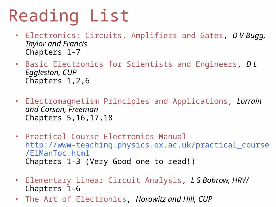
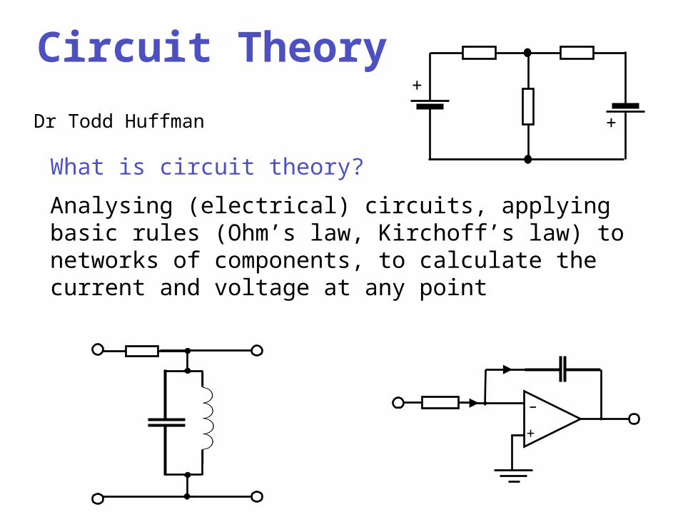
Reading List• Electronics: Circuits, Amplifiers and Gates, D V Bugg, Taylor and
FrancisChapters 1-7
• Basic Electronics for Scientists and Engineers, D L Eggleston, CUPChapters 1,2,6
• Electromagnetism Principles and Applications, Lorrain and Corson, FreemanChapters 5,16,17,18
• Practical Course Electronics Manual http://www-teaching.physics.ox.ac.uk/practical_course/ElManToc.htmlChapters 1-3 (Very Good one to read!)
• Elementary Linear Circuit Analysis, L S Bobrow, HRWChapters 1-6
• The Art of Electronics, Horowitz and Hill, CUP
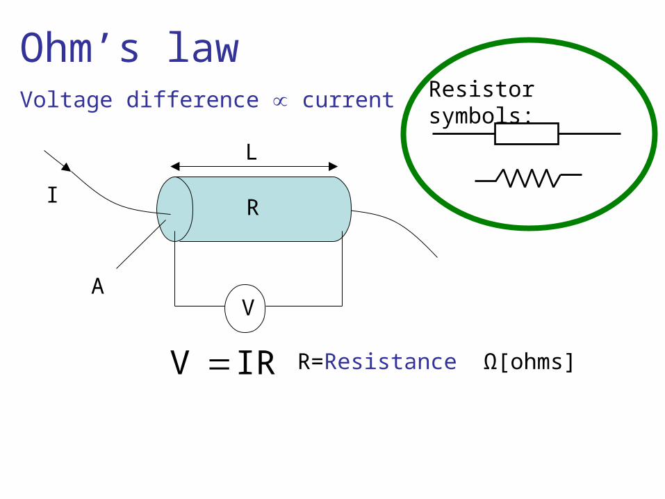
Ohm’s lawVoltage difference current
I
L
AV
IRV R=Resistance Ω[ohms]
Resistor symbols:
R
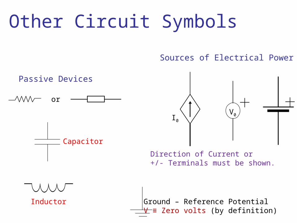
Other Circuit Symbols
I0
V0
Ground – Reference PotentialV ≡ Zero volts (by definition)
Passive Devices
Sources of Electrical Power
Direction of Current or+/- Terminals must be shown.
or
Capacitor
Inductor
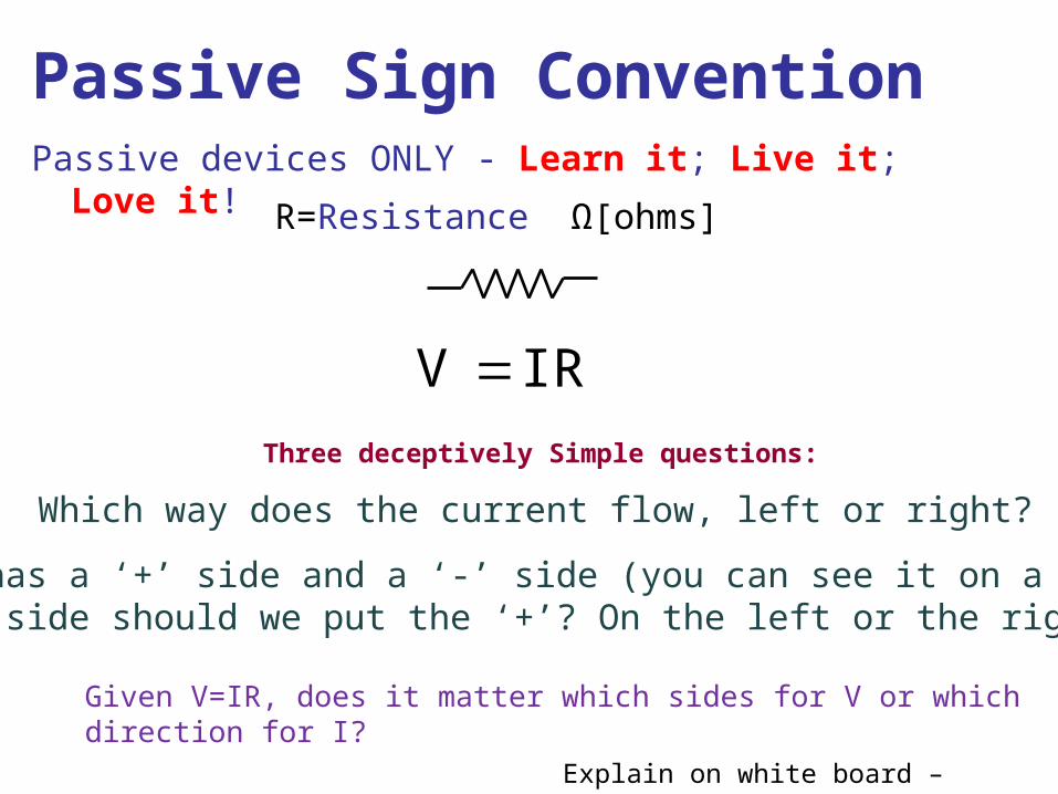
Passive Sign ConventionPassive devices ONLY - Learn it; Live it; Love it!
IRV
R=Resistance Ω[ohms]
Which way does the current flow, left or right?
Three deceptively Simple questions:
Voltage has a ‘+’ side and a ‘-’ side (you can see it on a battery)on which side should we put the ‘+’? On the left or the right?
Given V=IR, does it matter which sides for V or whichdirection for I?
Explain on white board – Trick
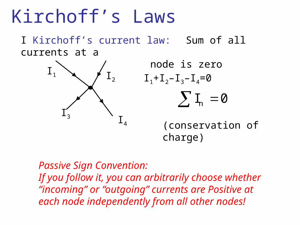
Kirchoff’s LawsI Kirchoff’s current law: Sum of all currents at a
node is zero
I1
I3
I2
I4
I1+I2–I3–I4=0
0In
(conservation of charge)
Passive Sign Convention: If you follow it, you can arbitrarily choose whether “incoming” or “outgoing” currents are Positive at each node independently from all other nodes!
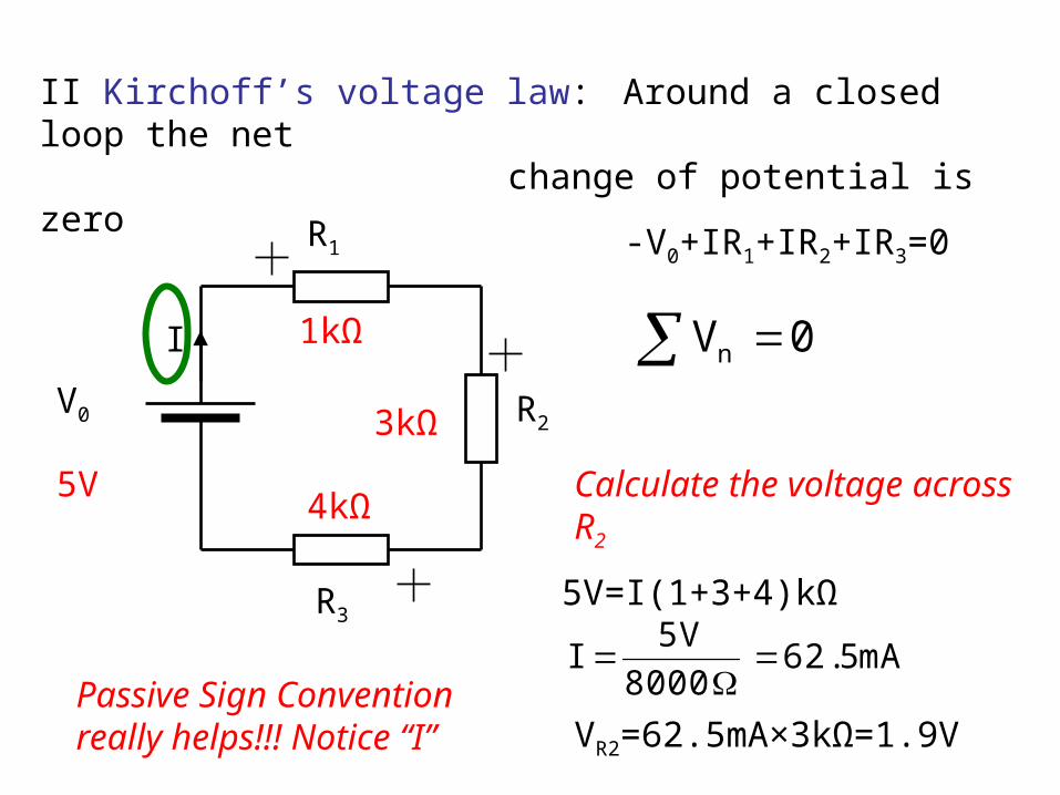
II Kirchoff’s voltage law: Around a closed loop the net change of potential is zero
V0
I
R1
R2
R3
-V0+IR1+IR2+IR3=0
0Vn
5V
3kΩ
4kΩCalculate the voltage across R2
5V=I(1+3+4)kΩ
mA5.628000
V5I
VR2=62.5mA×3kΩ=1.9V
1kΩ
Passive Sign Convention really helps!!! Notice “I”
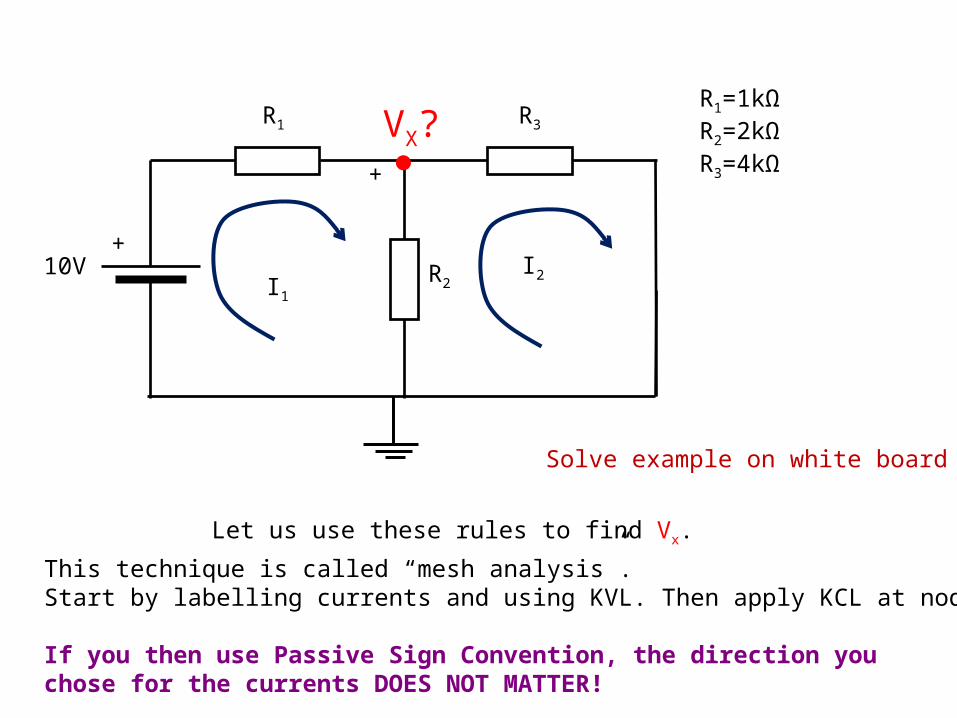
R1=1kΩR2=2kΩR3=4kΩ
10V+
R1 R3
R2
VX?
Let us use these rules to find Vx.
I1
I2
This technique is called “mesh analysis”.Start by labelling currents and using KVL. Then apply KCL at nodes.
If you then use Passive Sign Convention, the direction you chose for the currents DOES NOT MATTER!
Solve example on white board
+
10V+
R1 R3
R2
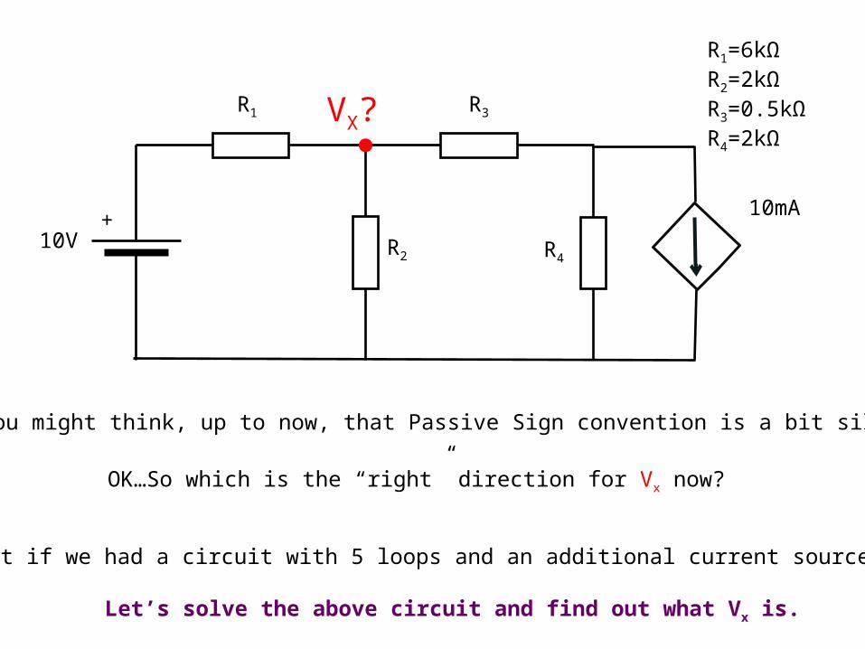
R1=6kΩR2=2kΩR3=0.5kΩR4=2kΩ
VX?
R4
10mA
OK…So which is the “right” direction for Vx now?
You might think, up to now, that Passive Sign convention is a bit silly.
What if we had a circuit with 5 loops and an additional current source?
Let’s solve the above circuit and find out what Vx is.
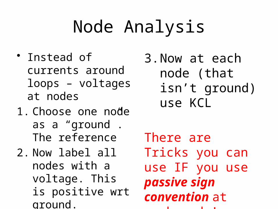
Node Analysis
• Instead of currents around loops – voltages at nodes
1. Choose one node as a “ground”. The reference
2. Now label all nodes with a voltage. This is positive wrt ground.
3. Now at each node (that isn’t ground) use KCL
There are Tricks you can use IF you use passive sign convention at each node!
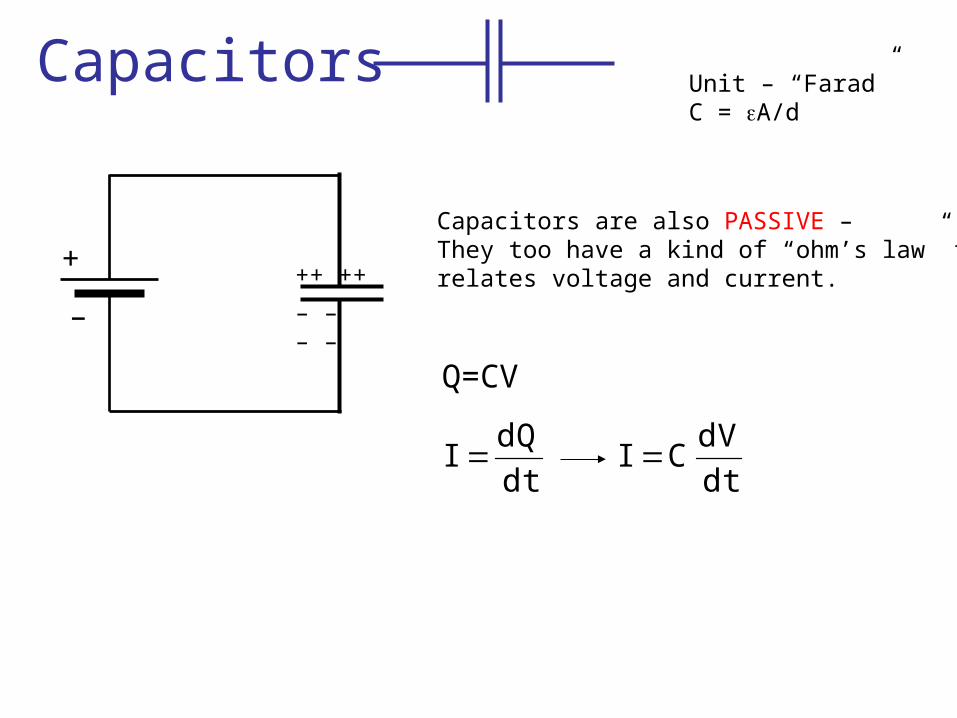
Capacitors
+ ++ ++
– – – ––
Q=CV
dtdQ
I dtdV
CI
Capacitors are also PASSIVE – They too have a kind of “ohm’s law” thatrelates voltage and current.
Unit – “Farad”C = eA/d
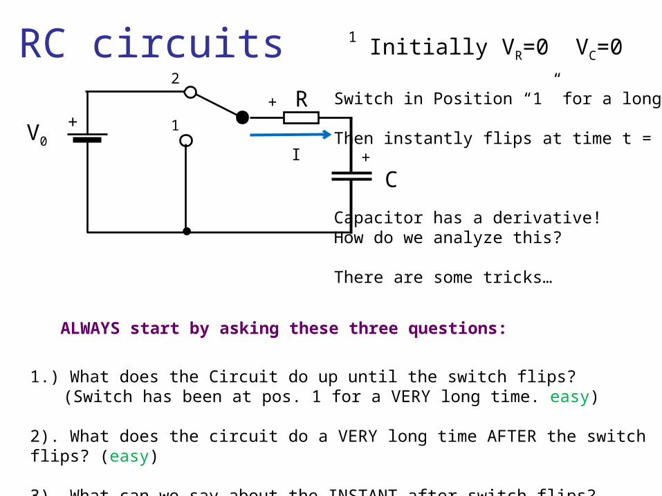
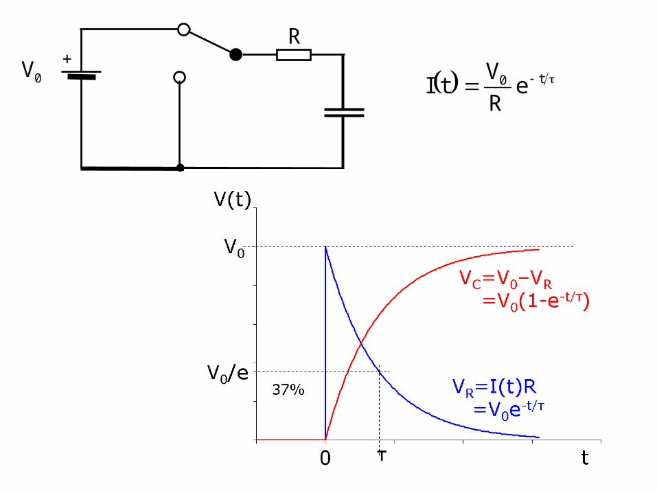
RC circuits
+V0
R
C
1
2
Initially VR=0 VC=01
Switch in Position “1” for a long time.
Then instantly flips at time t = 0.
Capacitor has a derivative!How do we analyze this?
There are some tricks…
1.) What does the Circuit do up until the switch flips?(Switch has been at pos. 1 for a VERY long time. easy)
2). What does the circuit do a VERY long time AFTER the switch flips? (easy)
3). What can we say about the INSTANT after switch flips? (easy if you know trick)
I
+
+
ALWAYS start by asking these three questions:
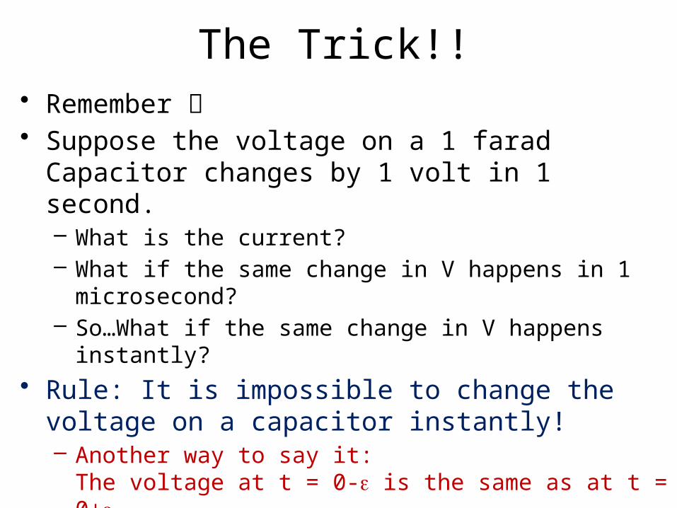
The Trick!!• Remember • Suppose the voltage on a 1 farad Capacitor changes
by 1 volt in 1 second.– What is the current?– What if the same change in V happens in 1 microsecond?– So…What if the same change in V happens instantly?
• Rule: It is impossible to change the voltage on a capacitor instantly!– Another way to say it:
The voltage at t = 0-e is the same as at t = 0+ .e
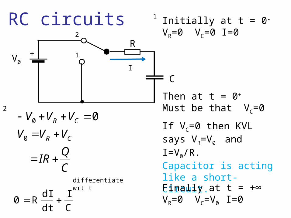
RC circuits
+V0
R
C
1
2
Initially at t = 0- VR=0 VC=0 I=0
1
2
C
QIR
VVV
VVV
CR
CR
0
0
0
CI
dtdI
R0
differentiate wrt t
Then at t = 0+ Must be that VC=0
If VC=0 then KVL says VR=V0 and I=V0/R.Capacitor is acting like a short-circuit.
Finally at t = +∞VR=0 VC=V0 I=0
I
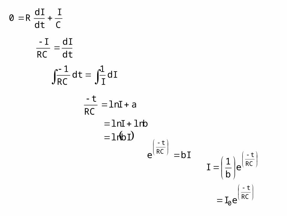
CI
dtdI
R0
dtdI
RCI
dII1
dtRC
1
bIln
blnIln
aIlnRC
t
bIe RCt
RCt
0
RCt
eI
eb1
I
t0 eRV
tI+V0
R
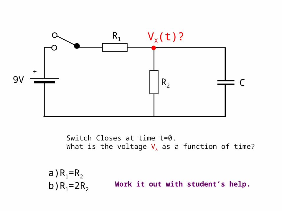
9V+
R1
R2
VX(t)?
C
a) R1=R2
b) R1=2R2
Switch Closes at time t=0. What is the voltage VX as a function of time?
Work it out with student’s help.
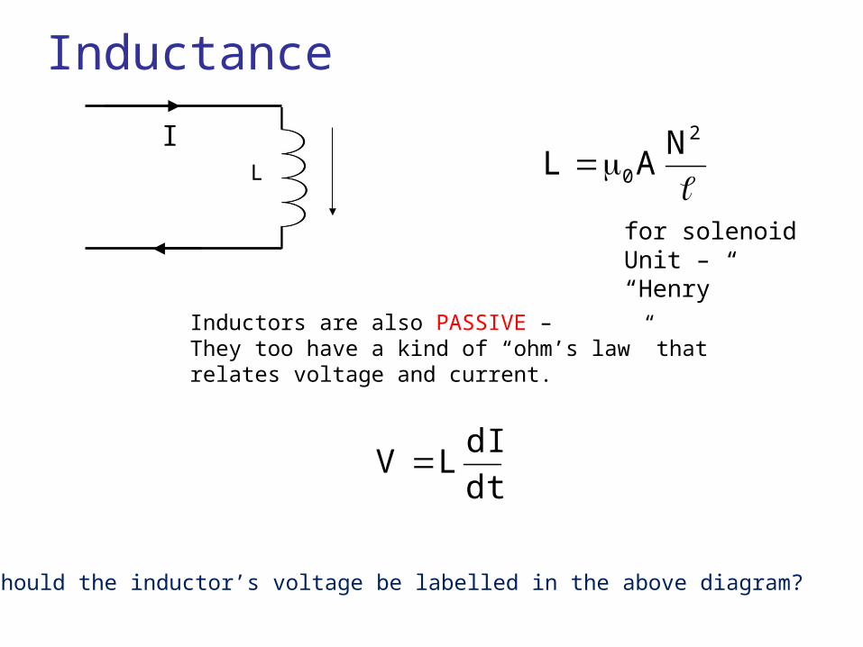
Inductance
I
dtdI
LV
2
0
NAL
for solenoidUnit – “Henry”
Inductors are also PASSIVE – They too have a kind of “ohm’s law” thatrelates voltage and current.
How should the inductor’s voltage be labelled in the above diagram?
L
RL circuits
+V0
R
L
1
2
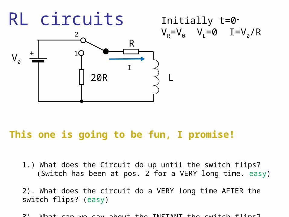
Initially t=0-
VR=V0 VL=0 I=V0/R
20R
1.) What does the Circuit do up until the switch flips?(Switch has been at pos. 2 for a VERY long time. easy)
2). What does the circuit do a VERY long time AFTER the switch flips? (easy)
3). What can we say about the INSTANT the switch flips? (easy if you know trick)
I
This one is going to be fun, I promise!
RL circuits
+V0
R
L
1
2
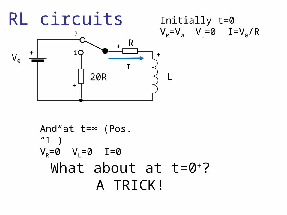
Initially t=0-
VR=V0 VL=0 I=V0/R
20RI
And at t=∞ (Pos. “1”)VR=0 VL=0 I=0
What about at t=0+?A TRICK!
+
+
+
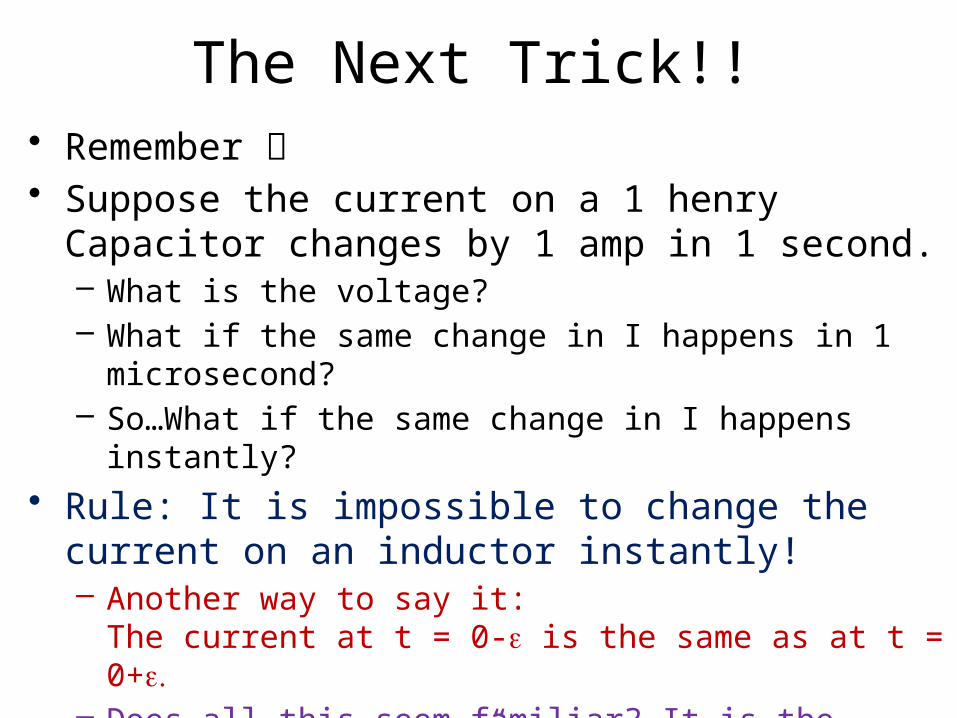
The Next Trick!!• Remember • Suppose the current on a 1 henry Capacitor changes
by 1 amp in 1 second.– What is the voltage?– What if the same change in I happens in 1 microsecond?– So…What if the same change in I happens instantly?
• Rule: It is impossible to change the current on an inductor instantly!– Another way to say it:
The current at t = 0-e is the same as at t = 0+ .e– Does all this seem familiar? It is the concept of
“duality”.
RL circuits
+V0
R
L
1
2
20R
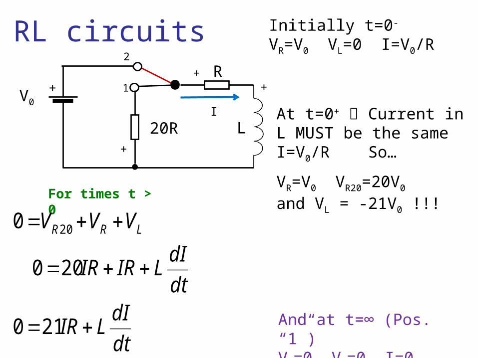
Initially t=0-
VR=V0 VL=0 I=V0/R
And at t=∞ (Pos. “1”)VR=0 VL=0 I=0
At t=0+ Current in L MUST be the sameI=V0/R So…
VR=V0 VR20=20V0
and VL = -21V0 !!!
I
+
++
dt
dILIR
dt
dILIRIR
VVV LRR
210
200
0 20
For times t > 0
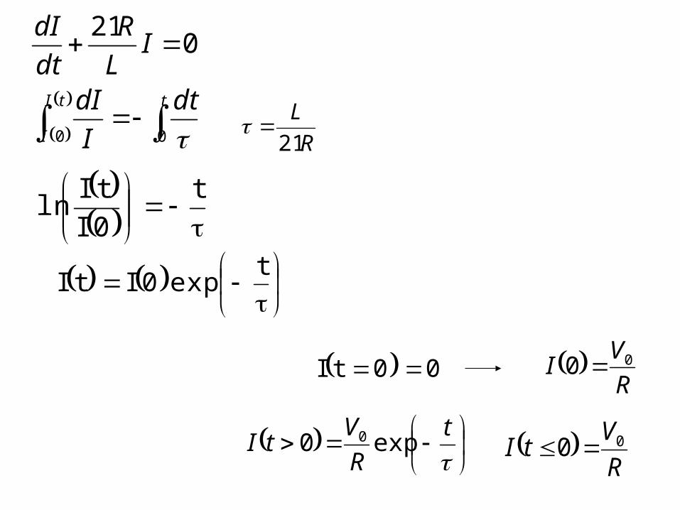
texp0ItI
ttI
I
dt
I
dI
IL
R
dt
dI
00
021
t0ItI
ln
R
L
21
00tI R
VI 00
t
R
VtI exp0 0
R
VtI 00
t
R
VtI exp0
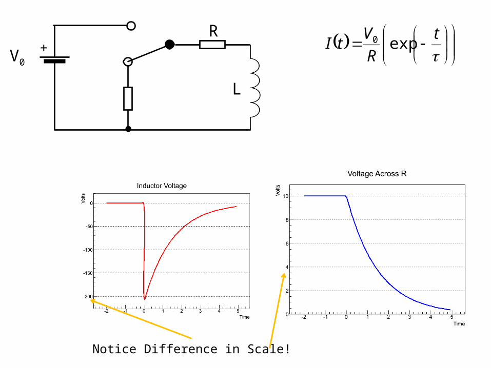
+V0
R
L
Notice Difference in Scale!
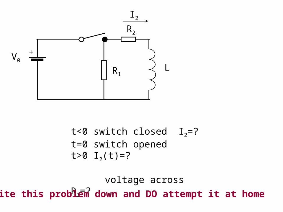
+V0
R2
R1L
I2
t<0 switch closed I2=?t=0 switch openedt>0 I2(t)=?
voltage across R1=?
Write this problem down and DO attempt it at home
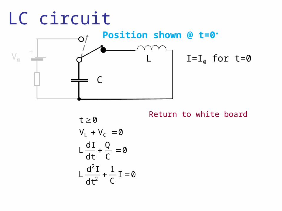
+V0
LC circuit
C
L I=I0 for t=0
0IC1
dt
IdL
0CQ
dtdI
L
0VV
0t
2
2
CL
Return to white board
Position shown @ t=0+
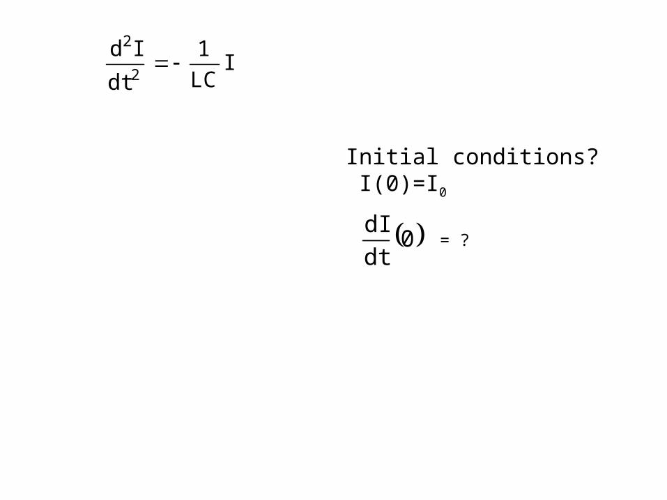
ILC1
dt
Id2
2
Initial conditions? I(0)=I0
0dtdI
= ?
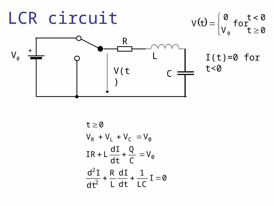
LCR circuit
+V0
R
C
L
V(t)
0t
0tfor
V
0tV
0
I(t)=0 for t<0
0ILC1
dtdI
LR
dt
Id
VCQ
dtdI
LIR
VVVV
0t
2
2
0
0CLR
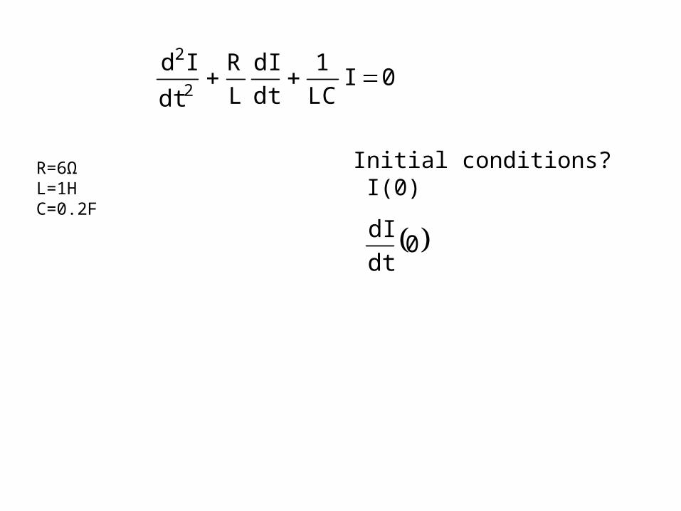
0ILC1
dtdI
LR
dt
Id2
2
R=6ΩL=1HC=0.2F
Initial conditions? I(0)
0dtdI

LCR circuit 20
2 t2
t1
21 ekekI
2,1 20
2
LC12
0
L2R
tt
CL2
2R
0 ee2
VtI
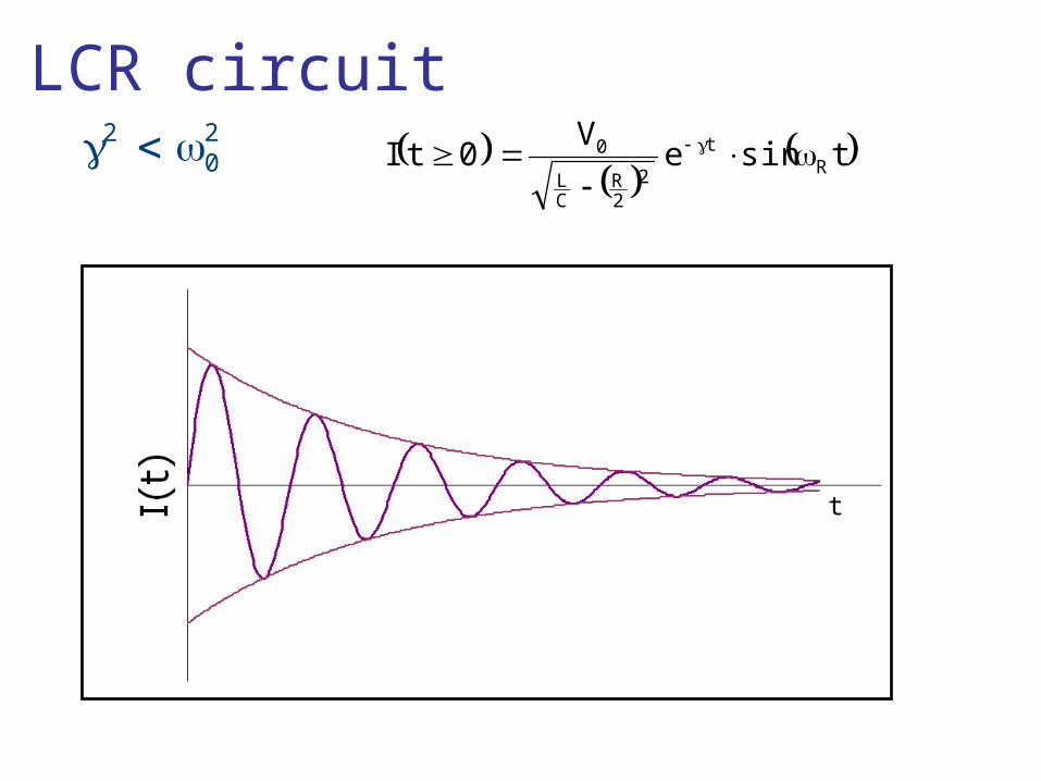
LCR circuit 2 2
0
tsineV
0tI Rt
22R
CL
0
t