
CIPer Model 50 Controller Product Data - 31-00197-02
12
CIPer TM MODEL 50 CONTROLLER PRODUCT DATA ® U.S. Registered Trademark Copyright © 2020 Honeywell Inc. • All Rights Reserved 31-00197-03 GENERAL CIPer Model 50 is a BACnet-compliant heating, ventilation, and air conditioning (HVAC) building controller. It runs the WEBs-N4 framework, integrating all trades in a building. Thus, CIPer Model 50 is the ideal solution for HVAC controls requiring combination with lighting, shading, access control, and security applications. It provides unparalleled energy efficiency through a vast HVAC Application Library. CIPer Model 50 enables uniform graphical operation, control, data logging, alarming, scheduling, and network management functions for HVAC and non- HVAC applications. Through its integrated web server, it allows real-time access to all information through web-based graphical views. CIPer Model 50 supports full remote engineering, including changes to the control program and the graphical user interface. This greatly supports the reduction of life cycle and maintenance costs. FEATURES • Reduced total installed cost: Existing standard Ethernet/LAN infrastructure is used for communication between CIPer Model 50 controllers, 3 rd -party BACnet® controllers, and BACnet® front-ends. Costs are further reduced by the flexible and optional use of Panel Bus I/Os (which allow manual override independent of the controller, thus eliminating the need for external switches) and of onboard I/Os. Panel Bus I/Os allow for wiring lengths of up to 2625 ft (800 m), thus eliminating the need to install a wire from field devices all the way back to the controller. • Reduced life cycle cost: CIPer Model 50 supports the highly reliable Honeywell Panel Bus I/O modules, which allow for plugging and replacing without any need for re-wiring or engineering, thus minimizing system downtime. The Panel Bus is polarity-insensitive, thus reducing potential wiring errors. Furthermore, Panel Bus I/O modules allow the predefinition of output safety positions, ensuring safe operation even if communication with CIPer Model 50 is disrupted. • Universal operation: Via Internet browser, CIPer Model 50 can be operated from any place, from any PC and/or mobile device connected to the (CIPer Model 50) network. Optionally, via the onboard or detached HMI, the controller can be operated independently of any network connection. • Vendor independence: Multiple international communication standards are supported, e.g.: BACnet/IP (ISO 16484-5); BACnet MS/TP (ISO 16484-5); LONWORKS (ISO 14908); Modbus RTU and Modbus TCP; M-Bus (EN 1434-3); oBIX; SNMP; etc. • Trending: Datapoints can be trended and historical values stored and viewed. • Reliable control performance: Embedded QNX ensures reliable, independent, and secure operation, especially for systems with Internet access. • Embedded email alarming: Configurable email alarming options allow alarms to be sent (via network or Internet-DSL connection) to email accounts and thus also to the mobile device using SMTP protocol. • Optional SMS alarming: SMS alarming via GSM modem using the optional SMS driver. • HVAC application library: Enables highly effective application generation for optimal energy-efficient control applications. • Flexible mounting options: Mounting onto a wall or onto panel back wall, into panel door, onto panel rail, and into sub-panels (fuse boxes). • Direct 24 VAC power supply: No batteries, no movable parts – thus does not require regular maintenance.
Transcript of CIPer Model 50 Controller Product Data - 31-00197-02

CIPerTM MODEL 50 CONTROLLER PRODUCT DATA
® U.S. Registered Trademark
Copyright © 2020 Honeywell Inc. • All Rights Reserved 31-00197-03
GENERAL
CIPer Model 50 is a BACnet-compliant heating, ventilation, and air conditioning (HVAC) building controller. It runs the WEBs-N4 framework, integrating all trades in a building.
Thus, CIPer Model 50 is the ideal solution for HVAC controls requiring combination with lighting, shading, access control, and security applications. It provides unparalleled energy efficiency through a vast HVAC Application Library.
CIPer Model 50 enables uniform graphical operation, control, data logging, alarming, scheduling, and network management functions for HVAC and non-HVAC applications. Through its integrated web server, it allows real-time access to all information through web-based graphical views.
CIPer Model 50 supports full remote engineering, including changes to the control program and the graphical user interface. This greatly supports the reduction of life cycle and maintenance costs.
FEATURES • Reduced total installed cost: Existing standard
Ethernet/LAN infrastructure is used for communication between CIPer Model 50 controllers, 3rd-party BACnet® controllers, and BACnet® front-ends. Costs are further reduced by the flexible and optional use of Panel Bus I/Os (which allow manual override independent of the controller, thus eliminating the need for external switches) and of onboard I/Os.
Panel Bus I/Os allow for wiring lengths of up to 2625 ft (800 m), thus eliminating the need to
install a wire from field devices all the way back to the controller.
• Reduced life cycle cost: CIPer Model 50 supports the highly reliable Honeywell Panel Bus I/O modules, which allow for plugging and replacing without any need for re-wiring or engineering, thus minimizing system downtime. The Panel Bus is polarity-insensitive, thus reducing potential wiring errors. Furthermore, Panel Bus I/O modules allow the predefinition of output safety positions, ensuring safe operation even if communication with CIPer Model 50 is disrupted.
• Universal operation: Via Internet browser, CIPer Model 50 can be operated from any place, from any PC and/or mobile device connected to the (CIPer Model 50) network. Optionally, via the onboard or detached HMI, the controller can be operated independently of any network connection.
• Vendor independence: Multiple international communication standards are supported, e.g.: BACnet/IP (ISO 16484-5); BACnet MS/TP (ISO 16484-5); LONWORKS (ISO 14908); Modbus RTU and Modbus TCP; M-Bus (EN 1434-3); oBIX; SNMP; etc.
• Trending: Datapoints can be trended and historical values stored and viewed.
• Reliable control performance: Embedded QNX ensures reliable, independent, and secure operation, especially for systems with Internet access.
• Embedded email alarming: Configurable email alarming options allow alarms to be sent (via network or Internet-DSL connection) to email accounts and thus also to the mobile device using SMTP protocol.
• Optional SMS alarming: SMS alarming via GSM modem using the optional SMS driver.
• HVAC application library: Enables highly effective application generation for optimal energy-efficient control applications.
• Flexible mounting options: Mounting onto a wall or onto panel back wall, into panel door, onto panel rail, and into sub-panels (fuse boxes).
• Direct 24 VAC power supply: No batteries, no movable parts – thus does not require regular maintenance.

CIPerTM MODEL 50 CONTROLLER — PRODUCT DATA
31-00197-03 2
Ordering Part Numbers
Table 1: Ordering Part Numbers
OS Number (SKU) Description
WEB-EHSERIESNX26D CIPer Model 50 PLANT CONTROLLER, with HMI, 26 IO, 100 points, 5 devices
WEB-EHSERIESNX26ND CIPer Model 50 PLANT CONTROLLER, without HMI, 26 IO, 100 points, 5 devices
WEBSEHN4LIC CIPer Model 50 Core License with SMA-0005-1YR-INT
PIN-0005 - 18 mo Maintenance
License Upgrades
Table 2: License Upgrades
Model License content/Upgrade license
EAGLEH255PUP 255 Additional Panel-bus Expansion I/O Points
PIN-DEV-UP-1 +50 open points upgrade, +1 Device
PIN-DEV-UP-2 +100 open points, +2 Devices
PIN-DEV-UP-10 +500 open points, +10 Devices
PIN-DEV-UP-25 +1250 open points, +25 Devices
PIN-DEV-UP-50 +2500 open points, +50 Devices
Software Maintenance Agreements
Table 3: Software Maintenance Agreements
Model License content/Upgrade license
SMA-0005-1YR PIN-0005 - 1 year maintenance
*SMA-0005-1YR-INIT PIN-0005 - Initial 18 month maintenance must be purchased in conjunction with the initial Core software. Optional 3 or 5 year maintenance may be substituted.
SMA-0005-3YR PIN-0005 - 3 year maintenance
SMA-0005-5YR PIN-0005 - 5 year maintenance
SMA-0010-1YR PIN-0010 - 1 year maintenance
SMA-0010-1YR-INIT PIN-0010 - Initial 18 month maintenance must be purchased in conjunction with the initial Core software. Optional 3 or 5 year maintenance may be substituted.
SMA-0010-3YR PIN-0010 - 3 year maintenance
SMA-0010-5YR PIN-0010 - 5 year maintenance
SMA-0025-1YR PIN-0025 - 1 year maintenance
SMA-0025-1YR-INIT PIN-0025 - Initial 18 month maintenance must be purchased in conjunction with the initial Core software. Optional 3 or 5 year maintenance may be substituted.
SMA-0025-3YR PIN-0025 - 3 year maintenance
SMA-0025-5YR PIN-0025 - 5 year maintenance
SMA-0100-1YR PIN-0100 - 1 year maintenance
SMA-0100-1YR-INIT PIN-0100 - Initial 18 month maintenance must be purchased in conjunction with the initial Core software. Optional 3 or 5 year maintenance may be substituted.
SMA-0100-3YR PIN-0100 - 3 year maintenance
SMA-0100-5YR PIN-0100 - 5 year maintenance
NOTE : *included with the initial purchase of WEBSEHN4LIC
CIPerTM MODEL 50 CONTROLLER — PRODUCT DATA
3 31-00197-03
OPERATION IN IP NETWORKS
When operating CIPer Model 50 in IP networks, either private (e.g. VPN) networks must be used or protection against the open Internet (e.g., by means of external firewalls) must be ensured. See Network Security on pg. 5.
OPERATOR INTERFACE
CIPer Model 50 is operated via a standard browser. By default, an integrated web server provides all freely programmable operation pages for full browser-based operation.
Operating devices can be laptops, desktops PCs, or touch screen PCs for direct flush mounting into electrical panel doors (IP65).
Figure 1: CIPer Model 50 PC homepage (example)
For mobile devices, there is a separate corresponding operator interface.
Figure 2: CIPer Model 50 mobile device homepage (example)
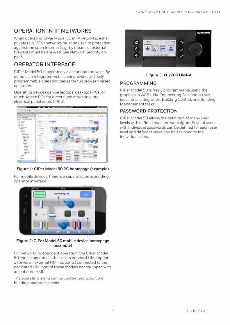
For network-independent operation, the CIPer Model 50 can be operated either via its onboard HMI (option 1) or via an external HMI (option 2) connected to the dedicated HMI port of those models not equipped with an onboard HMI.
The operating menu can be customized to suit the building operator's needs.
Figure 3: XL2000 HMI-A
PROGRAMMING
CIPer Model 50 is freely programmable using the graphics in WEBs-N4 Engineering Tool and is thus ideal for all Integration, Building Control, and Building Management tasks.
PASSWORD PROTECTION
CIPer Model 50 allows the definition of many user levels with defined read and write rights. Several users with individual passwords can be defined for each user level and different views can be assigned to the individual users.

CIPerTM MODEL 50 CONTROLLER — PRODUCT DATA
31-00197-03 4
COMMUNICATION PROTOCOLS
BACnet/IP – ISO 16484-5 and EN 13321-1
Communication with other CIPer Model 50, 3rd-party BACnet devices, and WEBs-N4 Supervisors is possible.
CIPer Model 50 conforms to the BACnet Building Controller (B-BC) profile.
BACnet MS/TP–ISO 16484-5 and EN 13321-1
Communication with other BACnet controllers is based on the international BACnet Protocol. Optionally, one or both of the onboard RS485 interfaces can be used for communication via BACnet MS/TP.
LonTalk® - ISO 14908
Optionally, communication with physical I/O modules, with room and zone controllers, and other LON devices.
LONWORKS communication requires the IF-LON2 LONWORKS interface.
MODBUS
Optionally, the two onboard RS485 interfaces can be used (even simultaneously) for communication via Modbus RTU. Modbus TCP communication is supported via the two onboard Ethernet RJ45 interfaces. See also, CIPer Model 50 Installation & Commissioning Instructions - 31-00233 for details.
M-Bus – EN 1434-3
Optionally, M-Bus communication is possible via the onboard RS232 interface. See also, CIPer Model 50 Installation & Commissioning Instructions - 31-00233 for details.
PANEL BUS
Optionally, one or both onboard RS485 interfaces can be used for Panel Bus communication with Honeywell Panel Bus I/O modules.
Up to 64 Panel Bus I/O modules can be operated via each RS485 interface, thus permitting 1,000+ Panel Bus / onboard I/O points (see Table 2: License Upgrades for information on upgrades).
HTTPS
Secure web browser communication is supported for web access via standard web browsers.
SMTP
Simple Mail Transfer Protocol is used for email alarming via network and Internet-DSL connection.
OPEN NIAGARA DRIVERS
Optionally, all available interfaces can also be used with any open Niagara driver. For example, the KNX driver can be used via the TCP/IP – KNX interface.
BUS AND PORT CONNECTIONS
WARNING
Risk of electric shock or equipment damage
• Do not touch any live parts in the cabinet
• Disconnect the power supply before making connections to or removing connections from terminals of the CIPer Model 50 controller or Panel Bus I/O modules.
• Do not reconnect the power supply until you have completed the installation.
• Due to the risk of short-circuiting (see Figure 9 on pg. 6), it is strongly recommended that the CIPer Model 50 controller be supplied with power from a dedicated transformer. However, if the CIPer Model 50 controller is to be supplied by the same transformer powering other controllers or devices (e.g., the PW M-Bus Adapter), care must be taken to ensure that correct polarity is observed.
• Observe the rules regarding electrostatic discharge.
Figure 4: Top view (with HMI and a full complement of onboard I/Os)
Figure 5: Side view
24V
-0
24V
~
1
7 8
2
J1 J8
9
DO
1
DO
2
DO
3
IN IN4
DO
4
DO
5
IN5
IN6
DO
6
DO
7
IN7
IN8
DO
8
GN
D
AO
1
AO
2
AO
3
5 6 7 8 9 10 11 12 13 14 15 16 17 18 19 20 21 22
AO
4
23
24 25 26 27 28 29 30 31 32
5 6
GN
D1
485-
1+
485-
1-
n.a
.
n.a
.
GN
D2
485-
2+
485-
2-
n.a
.
1 2 3 4
RS
232
RS485-1
EN
DB
IAS
MID
BI1
BI2
BI3
BI4
GN
D
UI1
UI2
UI3
UI4
UI5
UI6
UI7
33 34 35 36 37 38 39 40 41 42 43 44 45 46
UI8
47
UI9
UI1
0
2 1
1 2
EN
DB
IAS
MID
43

CIPerTM MODEL 50 CONTROLLER — PRODUCT DATA
5 31-00197-03
LEGEND
1. RS232 / RJ45 socket (for connection of M-Bus and other RS232-based protocols; factory debugging)
2. Three-position slide switch (for setting bias and termination resistance of RS485-1)
3. Two Ethernet / RJ45 sockets (for BACnet IP communication); 10/100 Mbit/s; 1 "link" LED + 1 "activity" LED
4. USB 2.0 Host Interface (for connection of IF-LON2); max. 200 mA, high speed
5. RS485-1* (isolated; for BACnet MS/TP, Panel Bus, Modbus RTU communication, etc.)
6. RS485-2* (non-isolated; for BACnet MS/TP, Panel Bus, Modbus RTU communication, etc.)
7. LEDs
8. USB 2.0 Device Interface (for connection to WEBs-N4 web browsers, and 3rd-party touch panels)
HMI (or RJ45 socket for connection of portable HMI)
*Modbus RTU Master/Slave communication is possible on the two RS485 interfaces.
WARNING
Risk of electric shock or equipment damage
It is prohibited to connect any of the RJ45 sockets of the CIPer Model 50 controller to a so-called PoE-enabled device ("Power over Ethernet").
M-BUS CONNECTION
The CIPer Model 50 controller supports M-Bus Master functionality via its onboard RS232 / RJ45 socket. It uses standard PW3/PW20/PW60 converters to connect to the M-Bus devices.
Wiring Topology
Max. bus length is 1050 feet. M-Bus devices are connected to the bus cable in parallel.
Figure 6: Allowed M-Bus wiring topology
Cables
See section "M-Bus Connection" in CIPer Model 50
Installation & Commissioning Instructions - 31-00233.
Use shielded, twisted pair cable Honeywell cable 3322 or 3251.
Shielding
Shielding is especially recommended when the M-Bus cable is installed in areas with expected or actual electromagnetic noise. Avoiding such areas is to be preferred.
Use shielded, twisted pair cable Honeywell cable 3322 or 3251 and connect the shield to noise-free earth ground – only once per M-Bus connection.
M-Bus Repeaters
The M-Bus can be extended to 3,000 feet, depending on the communication rate, and provided that the electrical limitations are observed. For details refer to the CIPer Model 50 Installation & Commissioning Instructions - 31-00233.
For bus length extension, M-Bus repeaters can be used, but have not been tested by Honeywell. Hence, it is the responsibility of the installing / commissioning personnel to ensure proper functioning.
M-BUS MASTER SPECIFICATIONS
For a detailed description of the M-Bus functionality, please refer to the M-Bus Online Help.
Physical Layer
RS232 to PW3/PW20/PW60
Physical connector: RS232 / RJ45 socket (see
Figure 5 on pg.3)
Cable order number: TECHTOO USB 3.0
YIOVVOM DB9 Breakout Connector
Communication rates:
300, 2,400, and 9,600 bps are supported, individually per M-Bus slave.
Max. no. of devices: 60 (excluding the CIPer Model 50 controller)
Cable and wiring specifications: See CIPer Model 50
Installation & Commissioning Instructions - 31-00233.
Address Range
M-Bus slaves can have a primary address between 1 and 250.
Measurement Cycle
Individually per M-Bus slave, the measurement cycle can be configured from 1 to 604,800 sec (i.e. 1 second to 7 days).
CIPer Model 50
SLAVE 1 SLAVE 2 SLAVE 3
PWCONVERTER
CIPerTM MODEL 50 CONTROLLER — PRODUCT DATA
6 31-00197-03
MODBUS CONNECTION
The CIPer Model 50 controller can function as a Modbus Master/Slave.
For Modbus RTU, the RS485 wiring rules must be followed.
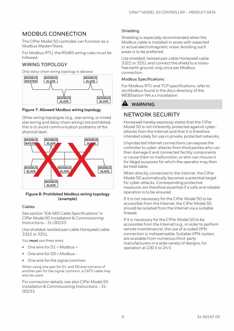
WIRING TOPOLOGY
Only daisy-chain wiring topology is allowed.
Figure 7: Allowed Modbus wiring topology
Other wiring topologies (e.g., star wiring, or mixed star wiring and daisy chain wiring) are prohibited; this is to avoid communication problems of the physical layer.
Figure 8: Prohibited Modbus wiring topology (example)
Cables
See section "EIA 485 Cable Specifications" in CIPer Model 50 Installation & Commissioning Instructions - 31-00233.
Use shielded, twisted pair cable Honeywell cable 3322 or 3251.
You must use three wires:
• One wire for D1 = Modbus +
• One wire for D0 = Modbus –
• One wire for the signal common
When using one pair for D1 and D0 and one wire of another pair for the signal common, a CAT5 cable may also be used.
For connection details, see also CIPer Model 50 Installation & Commissioning Instructions - 31-00233.
Shielding
Shielding is especially recommended when the Modbus cable is installed in areas with expected or actual electromagnetic noise. Avoiding such areas is to be preferred.
Use shielded, twisted pair cable Honeywell cable 3322 or 3251 and connect the shield to a noise-free earth ground, only once per Modbus connection.
Modbus Specifications
For Modbus RTU and TCP specifications, refer to docModbus found in the docs directory of the WEBStation-N4.x.x installation.
WARNING
NETWORK SECURITY
Honeywell hereby expressly states that the CIPer Model 50 is not inherently protected against cyber-attacks from the Internet and that it is therefore intended solely for use in private, protected networks.
Unprotected Internet connections can expose the controller to cyber-attacks from third parties who can then damage it and connected facility components or cause them to malfunction, or who can misuse it for illegal purposes for which the operator may then be held liable.
When directly connected to the Internet, the CIPer Model 50 automatically becomes a potential target for cyber-attacks. Corresponding protective measures are therefore essential if a safe and reliable operation is to be ensured.
If it is not necessary for the CIPer Model 50 to be accessible from the Internet, the CIPer Model 50 should be isolated from the Internet via a suitable firewall.
If it is necessary for the CIPer Model 50 to be accessible from the Internet (e.g., in order to perform remote maintenance), the use of a coded VPN connection is indispensable. Suitable VPN routers are available from numerous third-party manufacturers in a wide variety of designs, for operation at 230 V or 24 V.
MODBUSMASTER
MODBUSSLAVE
MODBUSSLAVE
MODBUSSLAVE
MODBUSSLAVE
MODBUSMASTER
MODBUSSLAVE
MODBUSSLAVE
MODBUSSLAVE
MODBUSSLAVE
MODBUSSLAVE
MODBUSSLAVE
XX

CIPerTM MODEL 50 CONTROLLER — PRODUCT DATA
7 31-00197-03
CONTROLLER SPECIFICATION
GENERAL
Table 4: Controller specifications
Ambient temperature
32..104°F (0...40°C), wall-mounting
32..122°F (0...50°C), cabinet/door mounting
Storage temperature
-4 … +158 °F (-20...70°C)
Humidity 5 … 95% r.h. non-condensing
Dimensions See Figure 10 and Figure 11 on pg. 10.
Degree of protection
IP20 (mounted on walls, with two accessory MVC-80-AC1 covers) IP30 (mounted in cabinet doors, with accessory MVC-80-AC2)
Fire class V0
Shock protection
Class II
Pollution degree 2
Installation Class 3
Rated impulse voltage
330 V for SELV, 2500 V for relay outputs
Overvoltage category
II
Automatic action
Type 1.C
Software class Class A
Ball-pressure test temperature
housing parts 167 °F (75°C)
terminals 257 °F (125°C)
ELECTRICAL DATA
Table 5. Electrical data
Power supply 19 … 29 VAC, 50/60 Hz, or
20 … 30 VDC
Power consumption
DC: 7 W (max. 9 W)
AC: 10 VA (max. 12 VA)
Heat dissipation Max. 9 W at DC power supply Max. 9 W at AC power supply
Current consumption
DC: 300 mA (max. 375 mA)
AC: 400 mA (max. 500 mA)
Due to the risk of short-circuiting (see Figure 9), it is strongly recommended that the CIPer Model 50 controller be supplied with power from a dedicated transformer. However, if the CIPer Model 50 controller is to be supplied by the same
transformer powering other controllers or devices (e.g., the PW M-Bus Adapter), care must be taken to ensure that correct polarity is observed.
Figure 9: Incorrect polarity → SHORT-CIRCUITING
MECHANICAL DATA
Table 6. Mechanical data
Housing Dimensions (L x B x T)
8.5 x 4.3 x 2.4 inches (215.5 x 110 x 61 mm)
Housing Material: ABS blend; flame retardant V0
Weight: 0.88lb (400 g) without packaging
Protection Class: IP 20
24 V~
24 V~0
LINE
L
N
CPU 1 CPU 2
NOISE-FREE EARTH GROUND(ONLY ONE PER SYSTEM)
N, L
EARTH GROUND
USB 2.0Device Interface
!REVERSEDPOLARITY!
PC 1 PC 2
2 21 1
24V~ 24V~24V~0 24V~0
SHORT-CIRCUITING!

CIPerTM MODEL 50 CONTROLLER — PRODUCT DATA
8 31-00197-03
CPU
Processor
NXP i.MX 6SoloX 32-bit dual core processor with 1 GHz
Arm® Cortex®-A9 core and 227 MHz Arm Cortex-M4 core
Operating System
QNX
Memory • 1 GB DDR3-RAM
• 512 KB MRAM
• 4 GB Flash Memory
Real-Time Clock
• Accuracy: ± 2 minutes per year (at typically, 77°F (25°C))
• Buffered typically for 72 h by gold capacitor
STANDARDS APPROVALS
• The device meets EN 60730-1, EN 60730-2-9, UL60730, and UL916.
• The device complies with Ethernet Protocol versions IEEEC 802.3.
• The device supports BACnet IP and BACnet MS/TP communications as per ANSI / ASHRAE 135-2012.
MOUNTING
The CIPer Model 50 controller is suitable for mounting as follows:
• In cabinets
• In fuse boxes conforming with standard DIN43880, and having a slot height of max. 45mm
• On walls (using accessory MVC-80-AC1 covers)
• in cabinet front doors (using accessory MVC-80-AC2)
ADDITIONAL PARTS
Table 7. Additional Parts
Order no. Description
XS830 Set of ten terminals. Each package consists of two groups of nine internally connected push-in terminals, for distributing signals/power.
XS831
Set of ten terminals. Each package consists of two groups of four pairs of push-in terminals (each with a 499 Ω resistor), for converting 0…20 mA signals into 0…10 VDC signals, and one push-in ground terminal per group.
TPU-11-01 Removable terminal plugs, push-in type; a complete set of 3 plugs (for terminals 1, 2, 24-32) for the WEB-EHSERIESNX26.
TPU-45-01 Removable terminal plugs, push-in type; a complete set of 9 plugs (for terminals 1 - 47) for the WEB-EHSERIESNX26.
MVC-80-AC1 Terminal cover (color: RAL9011); package of ten.
MVC-80-AC2 Front door mounting accessory (color: RAL9011) package of ten.
MVC-40-AC3 Strain relief; package of ten.
Pluggable Panel Bus I/O Modules
XF821A Pluggable Panel Bus Analog Input Module (with 8 analog inputs)
A1 A2 A3 A4 A5 A6 A7 A8 A9 B1 B2 B3 B4 B5 B6 B7 B8 B9
A1 B1 A2 B2 A3 B3 A4 B4 G1 G2A5 B5 A6 B6 A7 B7 A8 B8

CIPerTM MODEL 50 CONTROLLER — PRODUCT DATA
9 31-00197-03
XF822A Pluggable Panel Bus Analog Output Module (with 8 analog outputs)
XF823A Pluggable Panel Bus Binary Input Module (with 12 binary inputs)
XF824A Pluggable Panel Bus Relay Output Module (with 6 relay outputs)
Mixed Panel Bus I/O Modules with integrated socket
XF830A
Mixed Panel Bus I/O Module (with 8 analog inputs, 8 analog outputs, 12 binary inputs, and 6 relay outputs), with push-in terminals (incl. bridge connector and swivel label); housing matches XL800 design
XFU830A
Mixed Panel Bus I/O Module (with 8 analog inputs, 8 analog outputs, 12 binary inputs, and 6 relay outputs), with screw terminals (incl. bridge connector and swivel label); housing matches XL800 design
Terminal Sockets (not needed for the mixed I/O modules XF830A and XFU830A)
XS821-22 Push-in terminal socket for pluggable AI/AO modules (incl. bridge connector, swivel label)
XSU821-22 Screw-type terminal socket for pluggable AI/AO modules (incl. bridge connector, swivel label)
XS823 Push-in terminal socket for pluggable BI modules (incl. bridge connector, swivel label)
XSU823 Screw-type terminal socket for pluggable BI modules (incl. bridge connector, swivel label)
XS824-25 Push-in terminal socket for pluggable relay/floating output modules (incl. bridge connector, cross connector, swivel label)
XSU824-25 Screw-type terminal socket for pluggable relay/floating output modules (incl. bridge connector, cross connector, swivel label)

CIPerTM MODEL 50 CONTROLLER — PRODUCT DATA
10 31-00197-03
MODELS
Table 8. Overview of Models (hardware)
Feature Description Max. cable length
Order No.
Without HMI With HMI
WEB-EHSERIESNX26
ND
WEB-EHSERIESNX26D
UI*
NTC10kΩ (Type II) / NTC20kΩ (Type II) / 0…10V / slow BI, 0.4 Hz
1200 ft (366 m)
8 8
NTC10kΩ (Type II) / NTC20kΩ (Type II) / 0…10V fix pull-up / slow BI, 0.4 Hz
1200 ft (366 m)
2 2
BI open = 24 V / closed 2.0 mA / totalizer 15 Hz
1200 ft (366 m)
4 4
AO 0..11 V (max. 1 mA) 1200 ft (366 m)
4 4
BO
Relay N.O. contact: 3 A, 250 VAC, 30 VDC
1200 ft (366 m)
4 4
Relay N.O. contact (high in-rush): 10 A, 250 VAC, 30 VDC
1200 ft (366 m)
1 1
Relay N.O. contact with one common: 3 A, 250 VAC, 30 VDC
1200 ft (366 m)
3 3
Total I/Os -- 26 26
Bus interfaces
RS485-1, isolated, BACnet MS/TP, Panel Bus, or Modbus RTU Master or Slave communication
1)3600 ft
(1097 m) 1 1
RS485-2, non-isolated, BACnet MS/TP, Panel Bus, or Modbus RTU Master or Slave communication (NOTE: It is imperative that the RS485-2 be powered by a power supply having the proper polarity. Failure to do so will make data transmission impossible.)
1)3600 ft
(1097 m) 1 1
Ethernet Interfaces (email communication, browser access, BACnet IP communication, Niagara Network, Modbus TCP)
300 ft
(91.44 m) 2 2
USB 2.0 Device Interface (as Network Interface)
9 ft
(2.74 m) 1 1
USB 2.0 Host Interface (max. 200 mA) 9 ft
(2.74 m) 1 1
RS232 M-Bus communication via 45-feet-long PW3 / PW20 / PW60 converters
1)3600 ft
(1097 m) 1 1
LEDs
power LED (green) -- 1 1
status LED (red; indicates an active alarm; is controlled by Niagara Alarm System; is configurable)
-- 1 1
LED L1 (yellow; lit = Daemon starting; flashing = station starting; if L2 is also flashing, then the station has started)
-- 1 1

CIPerTM MODEL 50 CONTROLLER — PRODUCT DATA
11 31-00197-03
Feature Description Max. cable length
Order No.
Without HMI With HMI
WEB-EHSERIESNX26
ND
WEB-EHSERIESNX26D
LED L2 (yellow; lit = platform has started / is reachable; flashing = station has started / is reachable)
-- 1 1
bus status LEDs (for isolated RS485-1 interface)
-- 2 2
1) Depending upon bit rate. However, in the case of the configuration of RS485-2 for Panel Bus, the communication rate is set to 115.2 kbps, and the max. cable length is hence 2400 ft (731.52 m).
* Other supported sensor types are: NI1000 TK6180 DIN, NI1000 TK5000 DIN, PT1000-1, PT1000-2, BALCO500. Refer
to CIPer Model 50 Controller – Installation and Commissioning Instructions 31-00233, for more details.
DIMENSIONS
Figure 10: CIPer Model 50 controller (w/o HMI but with RJ45 socket for connection of portable HMI, and with the full complement of onboard I/Os), dimensions inches (mm)
4.33”(110)
2.4”(57.5)
1.94”(49.5)
8.4”(215.5)
2.05”(52)1.8”(45)
24V
-0
24
V~
1 2
DO
1
DO
2
DO
3
IN IN4
DO
4
DO
5
IN5
IN6
DO
6
DO
7
IN7
IN8
DO
8
GN
D
AO
1
AO
2
AO
3
5 6 7 8 9 10 11 12 13 14 15 16 17 18 19 20 21 22
AO
4
23
24 25 26 27 28 29 30 31 32
GN
D1
485-
1+
485-
1-
n.a
.
n.a
.
GN
D2
485-
2+
485-
2-
n.a
.
RS
232
RS485-1
EN
DB
IAS
MID
BI1
BI2
BI3
BI4
GN
D
UI1
UI2
UI3
UI4
UI5
UI6
UI7
33 34 35 36 37 38 39 40 41 42 43 44 45 46
UI8
47
UI9
UI1
0
2 1

CIPerTM MODEL 50 CONTROLLER — PRODUCT DATA
The material in this document is for information purposes only. The content and the product described are subject to change without notice. Honeywell makes
no representations or warranties with respect to this document. In no event shall Honeywell be liable for technical or editorial omissions or mistakes in this
document, nor shall it be liable for any damages, direct or incidental, arising out of or related to the use of this document . No part of this document may be
reproduced in any form or by any means without prior written permission from Honeywell.
Honeywell Building Technologies
1985 Douglas Drive North
Golden Valley, MN 55422
customer.honeywell.com
Honeywell Building Controls
® U.S. Registered Trademark
© 2020 Honeywell International Inc.
31-00197-03 | Rev 07-2021
Figure 11: CIPer Model 50 controller with covers, dimensions inches (mm)
NOTE: Use of the covers (MVC-80-AC1) will obstruct access to the Ethernet, USB 2.0, and RS232 interfaces.
2.4”(57.5)
2.05”(52)
8.4”(215.5)
J1 J8


