CIP 1 00 - CONCRETE IN PRACTICE
78
CIP 1 00 - CONCRE CIP 1 00 - CONCRE CIP 1 00 - CONCRE CIP 1 00 - CONCRE CIP 1 00 - CONCRETE IN PRACTICE TE IN PRACTICE TE IN PRACTICE TE IN PRACTICE TE IN PRACTICE CIP 1 Dusting Concrete Surfaces CIP 2 Scaling Concrete Surfaces CIP 3 Crazing Concrete Surfaces CIP 4 Cracking Concrete Surfaces CIP 5 Plastic Shrinkage Cracking CIP 6 Joints in Concrete Slabs on Grade CIP 7 Cracks in Concrete Basement Walls CIP 8 Discrepancies in Yield CIP 9 Low Concrete Cylinder Strength CIP 10 Strength of In-Place Concrete CIP 11 Curing In-Place Concrete CIP 12 Hot Weather Concreting CIP 13 Concrete Blisters CIP 14 Finishing Concrete Flatwork CIP 15 Chemical Admixtures for Concrete CIP 16 Flexural Strength of Concrete CIP 17 Flowable Fill Materials CIP 18 Radon Resistant Buildings CIP 19 Curling of Concrete Slabs CIP 20 Delamination of Troweled Concrete Surfaces CIP 21 Loss of Air Content in Pumped Concrete CIP 22 Grout CIP 23 Discoloration CIP 24 Synthetic Fibers for Concrete CIP 25 Corrosion of Steel in Concrete CIP 26 Jobsite Addition of Water CIP 27 Cold Weather Concreting CIP 28 Concrete Slab Moisture CIP 29 Vapor Retarders Under Slabs on Grade CIP 30 Supplementary Cementitious Materials CIP 31 Ordering Ready Mixed Concrete CIP 32 Concrete Pre-Construction Conference CIP 33 High Strength Concrete CIP 34 Making Concrete Cylinders in the Field CIP 35 Testing Compressive Strength of Concrete CIP 36 Structural Lightweight Concrete CIP 37 Self Consolidating Concrete (SCC) CIP 38 Pervious Concrete
Transcript of CIP 1 00 - CONCRETE IN PRACTICE

CIP 1 00 - CONCRECIP 1 00 - CONCRECIP 1 00 - CONCRECIP 1 00 - CONCRECIP 1 00 - CONCRETE IN PRACTICETE IN PRACTICETE IN PRACTICETE IN PRACTICETE IN PRACTICE
CIP 1 Dusting Concrete Surfaces
CIP 2 Scaling Concrete Surfaces
CIP 3 Crazing Concrete Surfaces
CIP 4 Cracking Concrete Surfaces
CIP 5 Plastic Shrinkage Cracking
CIP 6 Joints in Concrete Slabs on Grade
CIP 7 Cracks in Concrete Basement Walls
CIP 8 Discrepancies in Yield
CIP 9 Low Concrete Cylinder Strength
CIP 10 Strength of In-Place Concrete
CIP 11 Curing In-Place Concrete
CIP 12 Hot Weather Concreting
CIP 13 Concrete Blisters
CIP 14 Finishing Concrete Flatwork
CIP 15 Chemical Admixtures for Concrete
CIP 16 Flexural Strength of Concrete
CIP 17 Flowable Fill Materials
CIP 18 Radon Resistant Buildings
CIP 19 Curling of Concrete Slabs
CIP 20 Delamination of Troweled Concrete Surfaces
CIP 21 Loss of Air Content in Pumped Concrete
CIP 22 Grout
CIP 23 Discoloration
CIP 24 Synthetic Fibers for Concrete
CIP 25 Corrosion of Steel in Concrete
CIP 26 Jobsite Addition of Water
CIP 27 Cold Weather Concreting
CIP 28 Concrete Slab Moisture
CIP 29 Vapor Retarders Under Slabs on Grade
CIP 30 Supplementary Cementitious Materials
CIP 31 Ordering Ready Mixed Concrete
CIP 32 Concrete Pre-Construction Conference
CIP 33 High Strength Concrete
CIP 34 Making Concrete Cylinders in the Field
CIP 35 Testing Compressive Strength of Concrete
CIP 36 Structural Lightweight Concrete
CIP 37 Self Consolidating Concrete (SCC)
CIP 38 Pervious Concrete


Formation of loose powder resulting from disintegra-
tion of surface of hardened concrete is called dusting
or chalking. The characteristics of such surfaces are:
a. They powder under any kind of traffic
b. They can be easily scratched with a nail or even
by sweeping.
ust?
A concrete floor dusts under traffic because the wear-
ing surface is weak. This weakness can be caused by:
a. Any finishing operation performed while bleed wa-
ter is on the surface or before the concrete has fin-
ished bleeding. Working this bleed water back into
the top 1/4 inch [6 mm] of the slab produces a very
high water-cement ratio and, therefore, a low
strength surface layer.
b. Placement over a non-absorptive subgrade or poly-
ethylene vapor retarder. This reduces normal
absorption by the subgrade, increases bleeding and,
as a result, the risk of surface dusting.
c. Floating and/or troweling operations following the
condensation of moisture from warm humid air on
cold concrete. In cold weather concrete sets slowly,
in particular, cold concrete in basement floors. If
the humidity is relatively high, water will condense
on the freshly placed concrete, which, if troweled
into the surface, will cause dusting.
d. Inadequate ventilation in enclosed spaces. Carbon
dioxide from open salamanders, gasoline engines
or generators, power buggies or mixer engines may
cause a chemical reaction known as carbonation,
which greatly reduces the strength and hardness of
the concrete surface.
e. Insufficient curing. This omission often results
in a soft surface skin, which will easily dust under
foot traffic.
f. Inadequate protection of freshly placed concrete
from rain, snow or drying winds. Allowing the con-
crete surface to freeze will weaken the surface and
result in dusting.
a. Concrete with the lowest water content with an ad-
equate slump for placing and finishing will result
in a strong, durable, and wear-resistant surface. In
general, use concrete with a moderate slump not
exceeding 5 inches [125 mm]. Concrete with a
higher slump may be used provided the mixture is
designed to produce the required strength without
excessive bleeding and/or segregation. Water-re-
ducing admixtures are typically used to increase
Dusting concrete surface
WHY Do Concrete Floors Dust
WHAT is Dusting
HOW to Prevent Dusting
CIP 1 - Dusting Concrete SurCIP 1 - Dusting Concrete SurCIP 1 - Dusting Concrete SurCIP 1 - Dusting Concrete SurCIP 1 - Dusting Concrete Surfacesfacesfacesfacesfaces

slump while maintaining a low water content in the
mixture. This is particularly important in cold
weather when delayed set results in prolonged
bleeding.
b. NEVER sprinkle or trowel dry cement into the
surface of plastic concrete to absorb bleed water.
Remove bleed water by dragging a garden hose
across the surface. Excessive bleeding of concrete
can be reduced by using air-entrained concrete, by
modifying mix proportions, or by accelerating the
setting time.
c. DO NOT perform any finishing operations with
water present on the surface or while the concrete
continues to bleed. Initial screeding must be
promptly followed by bull floating. Delaying bull
floating operations can cause bleed water to be
worked into surface layer. Do not use a jitterbug,
as it tends to bring excess mortar to the surface.
DO NOT add water to the surface to facilitate fin-
ishing operations.
d. Do not place concrete directly on polyethylene
vapor retarders or non-absorptive subgrades as
this can contribute to problems such as dusting, scal-
ing, and cracking. Place 3 to 4 inches [75 to 100
mm] of a trimable, compactible fill, such as a
crusher-run material, over vapor retarders or non-
absorptive subgrade prior to concrete placement.
When high evaporation rates exist, lightly dampen
absorptive subgrades just prior to concrete place-
ment, ensuring that water does not pond or collect
on the subgrade surface.
e. Provide proper curing by using liquid membrane
curing compound or by covering the surface with
water, wet burlap, or other curing materials as soon
as possible after finishing to retain moisture in the
slab. It is important to protect concrete from the
environment at early ages.
f. Placing concrete in cold weather requires
concretetemperatures exceeding 50°F [10°C] as
well as an accelerating admixture.
a. Sandblast, shot blast or use a high-pressure washer
to remove the weak surface layer.
b. To minimize or eliminate dusting, apply a commer-
cially available chemical floor hardener, such as
sodium silicate (water glass) or metallic zinc or
magnesium fluosilicate, in compliance with
manufacturer’s directions on thoroughly dried
concrete. If dusting persists, use a coating, such as
latex formulations, epoxy sealers, or cement paint.
c. In severe cases, a serviceable floor can be obtained
by wet-grinding the surface to durable substrate
concrete. This may be followed by properly bonded
placement of a topping course. If this is not practical,
installation of a floor covering, such as carpeting or
vinyl tile covering, is the least expensive solution to
severe dusting. This option will require some prior
preparation since adhesives for floor covering mate-
rials will not bond to floors with a dusting problem
and dusting can permeate through carpeting.
References
1. Guide for Concrete Floor and Slab Construction, ACI 302.1R.
American Concrete Institute, Farmington Hills, MI.
2. Slabs on Grade, Concrete Craftsman Series CCS-1, American
Concrete Institute, Farmington Hills, MI.
3. Concrete Slab Surface Defects: Causes, Prevention, Repair,
IS177, Portland Cement Association, Skokie, IL
4. The Effect of Various Surface Treatments, Using Zinc and
Magnesium Fluosilicate Crystals on Abrasion Resistance of
Concrete Surfaces, Concrete Laboratory Report No. C-819,
U.S. Bureau of Reclamation.
5. Residential Concrete, National Association of Home Build-
ers, Washington, DC.
6. Trouble Shooting Guide for Concrete Dusting, Concrete Con-
struction, April 1996.
Follow These Rules to Prevent Dusting
1. Use moderate slump concrete not exceeding 5 inches [125 mm].
2. Do not start finishing operation while the concrete is bleeding.
3. Do not broadcast cement or sprinkle water on concrete prior to or during finishing operations.
4. Ensure that there is adequate venting of exhaust gases from gas-fired heaters in enclosed spaces.
5. Use adequate curing measures to retain moisture in concrete for the first 3 to 7 days and protect it from
HOW to Repair Dusting
1978, 1990 AND 1998

Scaling is local flaking or peeling of a finished sur-
face of hardened concrete as a result of exposure to
freezing and thawing. Generally, it starts as localized
small patches which later may merge and extend to
expose large areas. Light scaling does not expose the
coarse aggregate. Moderate scaling exposes the ag-
gregate and may involve loss of up to 1/8 to 3/8 inch
[3 to 10 mm] of the surface mortar. In severe scaling
more surface has been lost and the aggregate is clearly
exposed and
stands out.
Note—Occasionally concrete peels or scales in the absence of freez-
ing and thawing. This type of scaling is not covered in this CIP. Often
this is due to the early use of a steel trowel, over-finishing or finishing
while bleed water is on the surface. (see CIP 20 on Delaminations)
Scaling concrete surface
WHAT is Scaling
HOW to Prevent Scaling
CIP 2 - Scaling Concrete SurCIP 2 - Scaling Concrete SurCIP 2 - Scaling Concrete SurCIP 2 - Scaling Concrete SurCIP 2 - Scaling Concrete Surfacesfacesfacesfacesfaces
WHY Do Concrete Surfaces Scale
Concrete slabs exposed to freezing and thawing in the
presence of moisture and/or deicing salts are suscep-
tible to scaling. Most scaling is caused by:
a. The use of non-air-entrained concrete or too
little entrained air. Adequate air entrainment is re-
quired for protection against freezing and thawing
damage. However, even air-entrained concrete will
scale if other precautions, as listed below, are not
observed.
b. Application of excessive amounts of calcium or so-
dium chloride deicing salts on concrete with in-
adequate strength, air entrainment, or curing.
Chemicals such as ammonium sulfate or ammo-
nium nitrate, which are components of most fertil-
izers, can cause scaling as well as induce severe
chemical attack on the concrete surface.
c. Any finishing operation performed while bleed wa-
ter is on the surface. If bleed water is worked back
into the top surface of the slab, a high water-cement
ratio and, therefore, a low-strength surface layer
is produced. Overworking the surface during
finishing will reduce the air content in the surface
layer, making it susceptible to scaling in freezing
conditions.
d. Insufficient curing. This omission often results in a
weak surface skin, which will scale if it is exposed
to freezing and thawing in the presence of moisture
and deicing salts.
a. Concrete exposed to freezing and thawing cycles
must be air-entrained. Severe exposures require air
contents of 6 to 7 percent in freshly mixed concrete
made with 3/4-inch [19 mm] or 1-inch [25-mm]
aggregate. In moderate exposures, where deicing salts
will not be used, 4 to 6 percent air will be sufficient.
Air-entrained concrete of moderate slump (up to 5
inches [125 mm]) and adequate quality should be
used. In general, concrete strength of 3500 psi [24
MPa] for freezing and thawing exposure and 4000
psi [28 MPa] when deicers are used should be
adequate to prevent scaling.
b. DO NOT use deicing salts, such as calcium or
sodium chloride, in the first year after placing the
concrete. Use clean sand for traction. When
conditions permit, hose off accumulation of salt

HOW to Prevent Scaled Surfaces
1978, 1989, 1990 AND 1998
deposited by cars on newly placed driveways and
garage slabs. Subsequently, use salt sparingly.
Never use ammonium sulfate or ammonium
nitrate as a deicer; these are chemically aggres-
sive and destroy concrete surfaces. Poor drainage,
which permits water or salt and water to stand on
the surface for extended periods of time, greatly
increases the severity of the exposure and may
cause scaling. (This is often noticed in gutters
and sidewalks where the snow
from plowing keeps the surface wet for long
periods of time.)
c. Provide proper curing by using liquid membrane
curing compound or by covering the surface of
newly placed slab with wet burlap. Curing
ensures the proper reaction of cement with water,
known as hydration, which allows the concrete to
achieve its highest potential strength.
d. DO NOT perform any finishing operations with
water present on the surface. Bull floating must
promptly follow initial screeding. Delay finishing
operations until all the bleed water has risen to
and disappeared from the surface. This is critical
with air-entrained concrete in dry and windy
conditions where concrete that is continuing to
bleed may appear dry on the surface.
e. Do not use a jitterbug or vibrating screed with
high slump concrete, as it tends to form a weak
layer of mortar on the surface.
f. Protect concrete from the harsh winter en-
vironment. It is important to prevent the newly
placed concrete from becoming saturated with
water prior to freeze and thaw cycles during
winter months. Apply a commercially available
silane or siloxane-based breathable concrete
sealer or water repellent specifically designed for
use on concrete slabs. Follow the manufacturer’s
recommendations for application procedures and
frequency. Another option is a 1:1 mixture of
boiled linseed oil and mineral spirits applied in
two layers. The concrete should be reasonably
dry prior to the application of a sealer. Late
summer is the ideal time for surface treatment.
The sealer can be sprayed, brushed, or rolled on
the surface of the concrete. CAUTION: Linseed
oil will darken the color of the concrete and care
should be taken to apply it uniformly.
The repaired surface will only be as strong as the base
surface to which it is bonded. Therefore, the surface
to be repaired should be free of dirt, oil or paint and,
most importantly, it must be sound. To accomplish this,
use a hammer and chisel, sandblasting, high-pressure
washer, or jack hammer to remove all weak or unsound
material. The clean, rough, textured surface is then
ready for a thin bonded resurfacing such as:
a. Portland cement concrete resurfacing
b. Latex modified concrete resurfacing
c. Polymer-modified cementitious-based repair mor-
tar
References
1. Guide to Durable Concrete, ACI 201.2R, American
Concrete Institute, Farmington Hills, MI.
2. Scale-Resistant Concrete Pavements, IS117.02P, Portland
Cement Association, Skokie, IL.
3. Protective Coatings to Prevent Deterioration of Concrete by
Deicing Chemicals, National Cooperative Highway Research
Program Report No. 16.
4. Guide for Concrete Floor and Slab Construction, ACI 302.1R,
American Concrete Institute, Farmington Hills, MI.
5. Residential Concrete, National Association of Home Build-
ers, Washington, DC.
6. Slabs on Grade, Concrete Craftsman Series CCS-1, Ameri-
can Concrete Institute, Farmington Hills, MI.
7. Eugene Goeb, Deicer Scaling: An Unnecessary Problem,
Concrete Products, February 1994.
Follow These Rules to Prevent Scaling
1. For moderate to severe exposures, use air-entrained concrete of medium slump (3-5 in. [75-125 mm]) and cure properly.
2. Do not use deicers in the first winter.
3. Seal the surface with a commercial sealer or a mixture of boiled linseed oil and mineral spirits.
4. Use correct timing for all finishing operations and avoid the use of steel trowels for exterior concrete slabs.
5. Specify air-entrained concrete. In cold weather, concrete temperature should be at least 50°F [10°C], contain an accelerating
admixture, and be placed at a lower slump.

CIP 3 - Crazing Concrete Surfaces
WHY Do Concrete Surfaces Craze?
WHAT is Crazing?
Crazing is the development of a network of fine ran-
dom cracks or fissures on the surface of concrete or
mortar caused by shrinkage of the surface layer. These
cracks are rarely more than 1/8 inch [3 mm] deep and
are more noticeable on steel-troweled surfaces. The
irregular hexagonal areas enclosed by the cracks are
typically no more than 11/2 inch [40 mm] across and
may be as small as 1/2 or 3/8 inch [12 or 20 mm] in
unusual instances. Generally, craze cracks develop at
an early age and are apparent the day after placement
or at least by the end of the first week. Often they are
not readily visible until the surface has been wetted
and it is beginning to dry out.
Crazing cracks are sometimes referred to as shallow
map or pattern cracking. They do not affect the
structural integrity of concrete and rarely do they
affect durability or wear resistance. However, crazed
surfaces can be unsightly. They are particularly con-
spicuous and unsightly when concrete contains cal-
cium chloride, a commonly used accelerating admix-
ture.
Concrete surface crazing usually occurs because one
or more of the rules of “good concrete practices” were
not followed. The most frequent violations are:
a. Poor or inadequate curing. Environmental condi-
tions conducive to high evaporation rates, such as
low humidity, high temperature, direct sunlight, and
drying winds on a concrete surface when the con-
crete is just beginning to gain strength, cause rapid
surface drying resulting in craze cracking. Avoid
the delayed application of curing or even intermit-
tent wet curing and drying after the concrete has
been finished.
b. Too wet a mix, excessive floating, the use of a jit-
terbug or any other procedures that will depress
the coarse aggregate and produce an excessive
concentration of cement paste and fines at the
surface.
c. Finishing while there is bleed water on the sur-
face or the use of a steel trowel at a time when
the smooth surface of the trowel brings up too
much water and cement fines. Use of a bull float
or darby with water on the surface or while the
concrete continues to bleed will produce a high
water-cement ratio, weak surface layer which will
be susceptible to crazing, dusting and other sur-
face defects.
d. Sprinkling cement on the surface to dry up the
bleed water is a frequent cause of crazing. This
concentrates fines on the surface. Spraying wa-
ter on the concrete surface during finishing op-
erations will result in a weak surface susceptible
to crazing
or dusting.
e. Occasionally carbonation of the surface results
Crazing Concrete Surface (Dampened)

1978, 1989 AND 1998
in crazing as it causes shrinkage of the surface layer.
Carbonation is a chemical reaction between cement
and carbon dioxide or carbon monoxide from
unvented heaters. In such instances the surface will
be soft and will dust as well.
HOW to Prevent Crazing?
a. To prevent crazing, start curing the concrete as
soon as possible. Keep the surface wet by
either flooding with water, covering it with
damp burlap and keeping it continuously moist
for a minimum of 3 days, or spraying the surface
with a liquid-membrane curing compound. Avoid
alternate wetting and drying of concrete surfaces
at an early age. Curing retains the moisture
required for proper reaction of cement with water,
called hydration.
b. Use moderate slump (3 to 5 inches [75 to 125 mm])
concrete. Higher slump (up to 6 or 7 inches [150
to 175 mm]) can be used provided the mixture
is designed to produce the required strength
without excessive bleeding and/or segregation. This
is generally accomplished by using water-reducing
admixtures.
c. NEVER sprinkle or trowel dry cement or a mixture of
cement and fine sand on the surface of the plastic con-
crete to absorb bleed water. DO NOT sprinkle water
on the slab to facilitate finishing. Remove bleed wa-
ter by dragging a garden hose across the surface. DO
NOT perform any finishing operation while bleed
water is present on the surface or before the bleeding
process is completed. DO NOT overwork or over-fin-
ish the surface.
d. When high evaporation rates are possible, lightly
dampen the subgrade prior to concrete placement to
prevent it absorbing too much water from the con-
crete. If a vapor retarder is required on the subgrade,
cover it with 3 to 4 inches of a compactible,
granular fill, such as a crusher-run material to reduce
bleeding.
Follow These Rules to Prevent Crazing
1. Use moderate slump (3-5 inches) concrete with reduced bleeding characteristics.
2. Follow recommended practices and timing, based on concrete setting characteristics, for placing and
finishing operations:
a. Avoid excessive manipulation of the surface, which can depress the coarse aggregate, increase the
cement paste at the surface, or increase the water-cement ratio at the surface.
b. DO NOT finish concrete before the concrete has completed bleeding. DO NOT dust any cement onto the
surface to absorb bleed water. DO NOT sprinkle water on the surface while finishing concrete.
c. When steel troweling is required, delay it until the water sheen has disappeared from the surface.
3. Cure properly as soon as finishing has been completed.
References
1. Guide for Concrete Floor and Slab Construction, ACI 302.1R,
American Concrete Institute, Farmington Hills, MI.
2. Concrete Slab Surface Defects: Causes, Prevention, Repair, IS
177T, Portland Cement Association, Skokie, IL.
3. Ward Malisch, Avoiding Common Outdoor Flatwork Problems,
Concrete Construction, July 1990.
4. Ralph Spannenberg, Use the Right Tool at the Right Time, Con-
crete Construction, May 1996.
CIP 4 - Cracking Concrete Surfaces
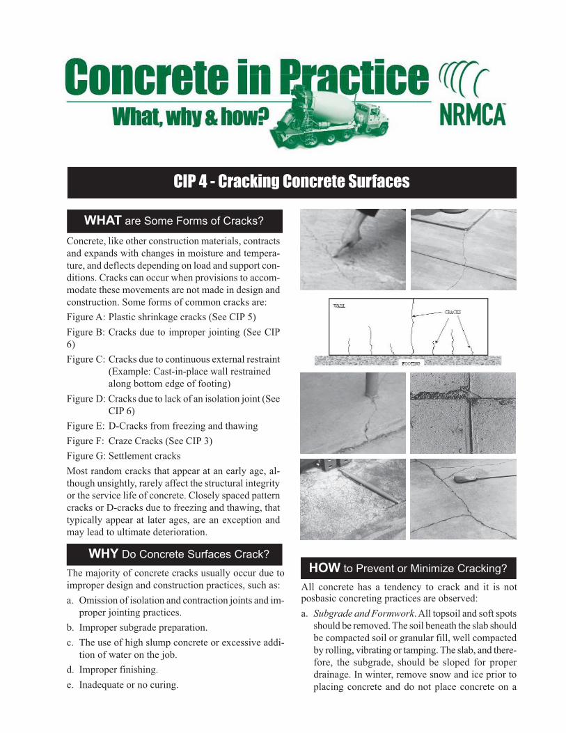
WHAT are Some Forms of Cracks?
Concrete, like other construction materials, contracts
and expands with changes in moisture and tempera-
ture, and deflects depending on load and support con-
ditions. Cracks can occur when provisions to accom-
modate these movements are not made in design and
construction. Some forms of common cracks are:
Figure A: Plastic shrinkage cracks (See CIP 5)
Figure B: Cracks due to improper jointing (See CIP
6)
Figure C: Cracks due to continuous external restraint
(Example: Cast-in-place wall restrained
along bottom edge of footing)
Figure D: Cracks due to lack of an isolation joint (See
CIP 6)
Figure E: D-Cracks from freezing and thawing
Figure F: Craze Cracks (See CIP 3)
Figure G: Settlement cracks
Most random cracks that appear at an early age, al-
though unsightly, rarely affect the structural integrity
or the service life of concrete. Closely spaced pattern
cracks or D-cracks due to freezing and thawing, that
typically appear at later ages, are an exception and
may lead to ultimate deterioration.
The majority of concrete cracks usually occur due to
improper design and construction practices, such as:
a. Omission of isolation and contraction joints and im-
proper jointing practices.
b. Improper subgrade preparation.
c. The use of high slump concrete or excessive addi-
tion of water on the job.
d. Improper finishing.
e. Inadequate or no curing.
HOW to Prevent or Minimize Cracking?
All concrete has a tendency to crack and it is notposbasic concreting practices are observed:
a. Subgrade and Formwork. All topsoil and soft spots
should be removed. The soil beneath the slab should
be compacted soil or granular fill, well compacted
by rolling, vibrating or tamping. The slab, and there-
fore, the subgrade, should be sloped for proper
drainage. In winter, remove snow and ice prior to
placing concrete and do not place concrete on a
WHY Do Concrete Surfaces Crack?
1978, 1989 AND 1998
frozen subgrade. Smooth, level subgrades help pre-
vent cracking. All formwork must be constructed
and braced so that it can withstand the pressure of
the concrete without movement. Vapor retarders di-
rectly under a concrete slab increase bleeding and
greatly increase the potential for cracking, espe-
cially with high-slump concrete. When a vapor re-
tarder is used, cover it with 3 to 4 inches of a com-
pactible granular fill, such as a crusher-run mate-
rial to reduce bleeding. Immediately prior to con-
crete placement, lightly dampen the subgrade,
formwork, and the reinforcement if severe drying
conditions exist.
b. Concrete. In general, use concrete with a moderate
slump (not over 5 inches [125 mm]). Avoid
retempering concrete to increase slump prior to
placement. Higher slump (up to 6 or 7 inches [150
to 175 mm]) can be used provided the mixture is
designed to produce the required strength without
excessive bleeding and/or segregation. This is gen-
erally accomplished by using water-reducing ad-
mixtures. Specify air-entrained concrete for outdoor
slabs subjected to freezing weather. (See CIP 2)
c. Finishing. Initial screeding must be promptly fol-
lowed by bull floating. DO NOT perform finishing
operations with water present on the surface or be-
fore the concrete has completed bleeding. Do not
overwork or over-finish the surface. For better trac-
tion on exterior surfaces use a broom finish. When
ambient conditions are conducive to a high evapo-
ration rate, use means to avoid rapid drying and
associated plastic shrinkage cracking by using wind
breaks, fog sprays, and covering the concrete
with wet burlap or polyethylene sheets between
finishing operations.
d. Curing. Curing is an important step to ensure du-
rable crack-resistant concrete. Start curing as soon
as possible. Spray the surface with liquid membrane
curing compound or cover it with damp burlap and
keep it moist for at least 3 days. A second applica-
tion of curing compound the next day is a good
quality assurance step.
e. Joints. Anticipated volumetric changes due to tem-
perature and/or moisture should be accommodated
by the construction of contraction joints by saw-
ing, forming or tooling a groove about 1/4 to 1/3 the
thickness of the slab, with a spacing between 24 to
36 times the thickness. Tooled and saw-cut joints
should be run at the proper time (CIP 6). A maxi-
mum 15 feet spacing for contraction joints is often
recommended. Panels between joints should be
square and the length should not exceed about 1.5
times the width. Isolation joints should be provided
whenever restriction to freedom of either vertical
or horizontal movement is anticipated—such as
where floors meet walls, columns, or footings.
These are full-depth joints and are constructed by
inserting a barrier of some type to prevent bond
between the slab and the other elements.
f. Cover Over Reinforcement. Providing sufficient
concrete cover (at least 2 inches [50 mm]) to keep
salt and moisture from contacting the steel should
prevent cracks in reinforced concrete caused by ex-
pansion of rust on reinforcing steel.
Follow These Rules to Minimize Cracking
1. Design the members to handle all anticipated loads.
2. Provide proper contraction and isolation joints.
3. In slab on grade work, prepare a stable subgrade.
4. Place and finish according to recommended and established practices.
5. Protect and cure the concrete properly.
References
1. Control of Cracking in Concrete Structures, ACI 224R, Ameri-
can Concrete Institute, Farmington Hills, MI.
2. Guide for Concrete Floor and Slab Construction, ACI 302.1R,
American Concrete Institute, Farmington Hills, MI.
3. Concrete Slab Surface Defects: Causes, Prevention, Repair,
IS177, Portland Cement Association, Skokie, IL.
4. Grant T. Halvorson, Troubleshooting Concrete Cracking Dur-
ing Construction, Concrete Construction, October 1993.
5. Cracks in Concrete: Causes, Prevention, Repair, A collection
of articles from Concrete Construction Magazine, June 1973.

CIP 5 - Plastic Shrinkage Cracking
WHAT is Plastic Shrinkage Cracking?
Plastic shrinkage cracks appear in the surface of fresh
concrete soon after it is placed and while it is still
plastic. These cracks appear mostly on horizontal sur-
faces. They are usually parallel to each other on the
order of 1 to 3 feet apart, relatively shallow, and gen-
erally do not intersect the perimeter of the slab. Plas-
tic shrinkage cracking is highly likely to occur when
high evaporation rates cause the concrete surface to
dry out before it has set.
Plastic shrinkage cracks are unsightly but rarely im-
pair the strength or durability of concrete floors and
pavements. The development of these cracks can be
minimized if appropriate measures are taken prior to
and during placing and finishing concrete.
(Note: Plastic shrinkage cracks should be distinguished from other
early or prehardening cracks caused by settlement of the concrete
around reinforcing bars, formwork movement, early age thermal
cracking, or differential settlement at a change from a thin to a
deep section of concrete.)
Plastic Shrinkage Cracks
Plastic shrinkage cracks are caused by a rapid loss of
water from the surface of concrete before it has set.
The critical condition exists when the rate of evapora-
tion of surface moisture exceeds the rate at which ris-
ing bleed water can replace it. Water receding below
the concrete surface forms menisci between the fine
particles of cement and aggregate causing a tensile force
to develop in the surface layers. If the concrete surface
has started to set and has developed sufficient tensile
strength to resist the tensile forces, cracks do not form.
If the surface dries very rapidly, the concrete may still
be plastic, and cracks do not develop at that time; but
plastic cracks will surely form as soon as the concrete
stiffens a little more. Synthetic fiber reinforcement in-
corporated in the concrete mixture can help resist the
tension when concrete is very weak.
WHY Do Plastic Shrinkage Cracks Occur?
Conditions that cause high evaporation rates from the
concrete surface, and thereby increase the possibility
of plastic shrinkage cracking, include:
• Wind velocity in excess of 5 mph
• Low relative humidity
• High ambient and/or concrete temperatures
Small changes in any one of these factors can signifi-
cantly change the rate of evaporation. ACI 305
(ref. 1) provides a chart to estimate the rate of evapo-
ration and indicates when special precautions might
be required. However, the chart isn’t infallible because
many factors other than rate of evaporation are in-
volved.
Concrete mixtures with an inherent reduced rate of
bleeding or quantity of bleed water are susceptible to
plastic shrinkage cracking even when evaporation
rates are low. Factors that reduce the rate or quantity
of bleeding include high cementitious materials con-
tent, high fines content, reduced water content, en-
trained air, high concrete temperature, and thinner
sections. Concrete containing silica fume requires
particular attention to avoid surface drying during place-
ment.
Any factor that delays setting increases the possibil-

1978, 1992 AND 1998
Follow These Rules to Minimize Plastic Shrinkage Cracking
1. Dampen the subgrade and forms when conditions for high evaporation rates exist.
2. Prevent excessive surface moisture evaporation by providing fog sprays and erecting windbreaks.
3. Cover concrete with wet burlap or polyethylene sheets between finishing operations.
4. Use cooler concrete in hot weather and avoid excessively high concrete temperatures in cold weather.
5. Cure properly as soon as finishing has been completed.
References
1. Hot Weather Concreting, ACI 305R, American Concrete
Institute, Farmington Hills, MI.
2. Guide for Concrete Floor and Slab Construction, ACI
302.1R, American Concrete Institute, Farmington Hills, MI.
3. Standard Practice for Curing Concrete, ACI 308, American
Concrete Institute, Farmington Hills, MI.
4. Concrete Slab Surface Defects: Causes, Prevention, Repair,
IS177, Portland Cement Association, Skokie, IL.
5. Bruce A. Suprenant, Curing During the Pour, Concrete Con-
struction, June 1997.
6. Eugene Goeb, Common Field Problems, Concrete Construc-
tion, October 1985.
HOW to Minimize Plastic Shrinkage Cracking?
ity of plastic shrinkage cracking. Delayed setting can
result from a combination of one or more of the fol-
lowing: cool weather, cool subgrades, high water con-
tents, lower cement contents, retarders, some water
reducers, and supplementary cementing materials.
Attempts to eliminate plastic shrinkage cracking by
modifying the composition to affect bleeding charac-
teristics of a concrete mixture have not been found to
be consistently effective. To reduce the potential for
plastic shrinkage cracking, it is important to recog-
nize ahead of time, before placement, when weather
conditions conducive to plastic shrinkage cracking
will exist. Precautions can then be taken to mini-
mize its occurrence.
a. When adverse conditions exist, erect temporary wind-
breaks to reduce the wind velocity over the surface of
the concrete and, if possible, provide sunshades to
control the surface temperature of the slab. If condi-
tions are critical, schedule placement to begin in the
later afternoon or early evening. However, in very
hot conditions, early morning placement can afford
better control on concrete temperatures.
b. In the very hot and dry periods, use fog sprays to
discharge a fine mist upwind and into the air above
the concrete. Fog sprays reduce the rate of evapo-
ration from the concrete surface and should be con-
tinued until suitable curing materials can be applied.
c. If concrete is to be placed on a dry absorptive
subgrade in hot and dry weather, dampen the
subgrade but not to a point that there is freestand-
ing water prior to placement. The formwork and
reinforcement should also be dampened.
d. The use of vapor retarders under a slab on grade greatly
increases the risk of plastic shrinkage cracking. If a
vapor retarder is required, cover it with a 3 to 4 inch
lightly dampened layer of a trimable, compactible
granular fill, such as a crusher-run material (ref. 2).
e. Have proper manpower, equipment, and supplies
on hand so that the concrete can be placed and fin-
ished promptly. If delays occur, cover the concrete
with moisture-retaining coverings, such as wet bur-
lap, polyethylene sheeting or building paper, be-
tween finishing operations. Some contractors find
that plastic shrinkage cracks can be prevented in
hot dry climates by spraying an evaporation re-
tardant on the surface behind the screeding op-
eration and following floating or troweling, as
needed, until curing is started.
f. Start curing the concrete as soon as possible. Spray
the surface with liquid membrane curing compound
or cover the surface with wet burlap and keep it
continuously moist for a minimum of 3 days.
g. Consider using synthetic fibers (ASTM C 1116) to
resist plastic shrinkage cracking.
h. Accelerate the setting time of concrete and avoid
large temperature differences between concrete and
air temperatures.
If plastic shrinkage cracks should appear during final fin-
ishing, the finisher may be able to close them by refin-
ishing. However, when this occurs precautions, as dis-
cussed above, should be taken to avoid further cracking.

CIP 6 - Joints in Concrete Slabs on Grade
WHAT are Joints?
WHY are Joints Constructed?
Concrete expands and shrinks with changes in mois-
ture and temperature. The overall tendency is to shrink
and this can cause cracking at an early age. Irregular
cracks are unsightly and difficult to maintain but gen-
erally do not affect the integrity of concrete. Joints
are simply pre-planned cracks. Joints in concrete slabs
can be created by forming, tooling, sawing, and place-
ment of joint formers.
Some forms of joints are:
a. Contraction joints – are intended to create weak-
ened planes in the concrete and regulate the loca-
tion where cracks, resulting from dimensional
changes, will occur.
b. Isolation or expansion joints – separate or isolate
slabs from other parts of the structure, such as walls,
footings, or columns; and driveways and patios
from sidewalks, garage slabs, stairs, lightpoles and
other points of restraint. They permit independent
vertical and horizontal movement between adjoin-
ing parts of the structure and help minimize crack-
ing when such movements are restrained.
c. Construction joints – are surfaces where two suc-
cessive placements of concrete meet. They are typi-
cally placed at the end of a day’s work but may be
required when concrete placement is stopped for
longer than the initial setting time of concrete. In
slabs they may be designed to permit movement
and/or to transfer load. The location of construc-
tion joints should be planned. It may be desir-
able to achieve bond and continue reinforcement
through a construction joint.
Cracks in concrete cannot be prevented entirely, but
they can be controlled and minimized by properly de-
signed joints. Concrete cracks because:
a. Concrete is weak in tension and, therefore, if its
natural tendency to shrink is restrained, tensile
stresses that exceed its tensile strength can develop,
resulting in cracking.
b. At early ages, before the concrete dries out, most
cracking is caused by temperature changes or by
the slight contraction that takes place as the con-
crete sets and hardens. Later, as the concrete dries,
it will shrink further and either additional cracks
may form or preexisting cracks may become wider.
Joints provide relief from the tensile stresses, are easy
to maintain and are less objectionable than uncon-
trolled or irregular cracks.
How to Construct Joints?
Joints must be carefully designed and properly con-
structed if uncontrolled cracking of concrete flatwork
is to be avoided. The following recommended prac-
tices should be observed:
a. The maximum joint spacing should be 24 to 36
times the thickness of the slab. For example, in a
4-inch [100 mm] thick slab the joint spacing should

1979, 1989 AND 1998
Follow These Rules for Proper Jointing
1. Plan exact location of all joints, including timing of contraction joint sawing before construction.
2. Provide isolation joints between slabs and columns, walls and footings, and at junctions of driveways with
walks, curbs or other obstructions.
3. Provide contraction joints and joint filling materials as outlined in specifications.
References
1. Joints in Concrete Construction, ACI 224.3R, American Con-
crete Institute, Farmington Hills, MI.
2. Guide for Concrete Floor and Slab Construction, ACI 302.1R,
American Concrete Institute, Farmington Hills, MI.
3. Slabs on Grade, ACI Concrete Craftsman Series CCS-1, Ameri-
can Concrete Institute, Farmington Hills, Ml.
4. Joint Planning Primer, Concrete Construction, August 1997.
5. Bruce A. Suprenant, Sawcutting Joints in Concrete, Concrete
Construction, January 1995.
be about 10 feet [3 m]. It is further recommended
that joint spacing be limited to a maximum of 15
feet [4.5 m].
b. All panels should be square or nearly so. The length
should not exceed 1.5 times the width. Avoid
L-shaped panels.
c. For contraction joints, the joint groove should have
a minimum depth of 1/4 the thickness of the slab,
but not less than 1 inch [25 mm]. Timing of joint-
ing operations depends on the method used:
• Preformed plastic or hard board joint strips are
inserted into the concrete surface to the required
depth before finishing.
• Tooled joints must be run early in the finishing
process and rerun later to ensure groove bond
has not occurred.
• Early-entry dry-cut joints are generally run 1 to
4 hours after completion of finishing, depend-
ing on the concrete’s setting characteristics.
These joints are typically not as deep as those
obtained by the conventional saw-cut process,
but should be a minimum of 1 inch [25 mm] in
depth.
• Conventional saw-cut joints should be run
within 4 to 12 hours after the concrete has
been finished.
d. Raveling during saw cutting is affected by the
strength of the concrete and aggregate characteris-
tics. If the joint edges ravel during sawing, it
must be delayed. However, if delayed too long,
sawing can become difficult and uncontrolled
cracking may occur.
e. Use premolded joint filler such as asphalt-impreg-
nated fiber sheeting, compressible foam strips, or
similar materials for isolation joints to separate slabs
from building walls or footings. At least 2 inches
[50 mm] of sand over the top of a footing will also
prevent bond to the footing.
f. To isolate columns from slabs, form circular or
square openings, which will not be filled until after
the floor has hardened. Slab contraction joints
should intersect at the openings for columns. If
square openings are used around columns, the
square should be turned at 45 degrees so the con-
traction joints intersect at the diagonals of the
square.
g. If the slab contains wire mesh, cut out alternate
wires, or preferably discontinue the mesh, across
contraction joints. Note that wire mesh will not pre-
vent cracking. Mesh tends to keep the cracks and
joints tightly closed.
h. Construction joints key the two edges of the slab
together either to provide transfer of loads or to
help prevent curling or warping of the two adja-
cent edges. Galvanized metal keys are sometimes
used for interior slabs, however, a beveled
1 by 2 inch [25 by 50 mm] strip, nailed to bulk-
heads or form boards, can be used in slabs that are
at least 5 inches [125 mm] thick to form a key which
will resist vertical loads and movements. Keyed
joints are not recommended for industrial floors.
Metal dowels should be used in slabs that will carry
heavy loads. Dowels must be carefully lined up and
parallel or they may induce restraint and cause ran-
dom cracking at the end of the dowel.
i. Joints in industrial floors subject to heavy traffic
require special attention to avoid spalling of joint
edges. Such joints should be filled with a material
capable of supporting joint edges. Manufacturer’s
recommendations and performance records should
be checked before use.

CIP 7 - Cracks in Concrete Basement Walls
WHAT Types of Cracks May Occur?
WHY do Basement Cracks Occur?
Cast-in-place concrete basements provide durable, high
quality extra living space. At times undesirable cracks
occur. They result from:
a. Temperature and drying shrinkage cracks. With few
exceptions, newly placed concrete has the largest vol-
ume that it will ever have. Shrinkage tendency is in-
creased by excessive drying and/or a significant drop
in temperature that can lead to random cracking if steps
are not taken to control the location of the cracks by
providing control joints. When the footing and wall
are placed at different times, the shrinkage rates differ
and the footing restrains the shrinkage in the wall caus-
ing cracking. Lack of adequate curing practices can
also result in cracking.
b. Settlement cracks. These occur from non-uniform
support of footings or occasionally from expansive
soils.
c. Other structural cracks. In basements these cracks
generally occur during backfilling, particularly when
heavy equipment gets too close to the walls.
d. Cracks due to lack of joints or improper jointing prac-
tices.
In concrete basement walls some cracking is normal. Most
builders or third party providers offer limited warranties
for basements. A typical warranty will require repair only
when cracks leak or exceed the following:
Crack Vertical
Width Displacement
Basement Walls .......................... 1/8" (3-mm) –
Basement Floors ......................... 3/16" (12-mm) 1/8" (12-mm)
Garage Slabs .............................. 1/4" (12-mm) 1/4" (12-mm)
The National Association of Homebuilders requires repair
or corrective action when cracks in concrete basements walls
allow exterior water to leak into the basement.
If the following practices are followed the cracking is
minimized:
a. Uniform soil support is provided.
b. Concrete is placed at a moderate slump - up to about
5 inches (125 mm) and excessive water is not added
at the jobsite prior to placement.
c. Proper construction practices are followed.
d. Control joints are provided every 20 to 30 feet (6 to 9
m).
e. Backfilling is done carefully and, if possible, waiting
until the first floor is in place in cold weather. Con-
crete gains strength at a slower rate in cold weather.
f. Proper curing practices are followed.
How to Construct Quality Basements?
Since the performance of concrete basements is affected
by climate conditions, unusual loads, materials quality
and workmanship, care should always be exercised in
their design and construction. The following steps should
be followed:
a. Site conditions and excavation. Soil investigation
should be thorough enough to insure design and con-
struction of foundations suited to the building site.
The excavation should be to the level of the bottom
of the footing. The soil or granular fill beneath the
entire area of the basement should be well compacted
by rolling, vibrating or tamping. Footings must bear
on undisturbed soil.

1979 AND 2000
b. Formwork and reinforcement. All formwork must
be constructed and braced so that it can withstand the
pressure of the plastic concrete. Reinforcement is ef-
fective in controlling shrinkage cracks and is espe-
cially beneficial where uneven side pressures against
the walls may be expected. Observe state and local
codes and guidelines for wall thickness and reinforce-
ment.
c. Joints. Shrinkage and temperature cracking of base-
ment walls can be controlled by means of properly
located and formed joints. As a rule of thumb, in 8-ft.
(2.5-m) high and 8-inch (200-mm) thick walls, verti-
cal control joints should be provided at a spacing of
about 30 times the wall thickness. These wall joints
can be formed by nailing a 3/4-inch (20-mm) thick strip
of wood, metal, plastic or rubber, beveled from 3/4 to1/2 inch (20 to 12-mm) in width, to the inside of both
interior and exterior wall forms. The depth of the
grooves should be at least 1/4 the wall thickness. After
the removal, the grooves should be caulked with a
good quality joint filler. For large volume pours or
with abrupt changes in wall thickness, bonded con-
struction joints should be planned before construc-
tion. The construction joints may be horizontal or
vertical. Wall reinforcement continues through a con-
struction joint.
d. Concrete. In general, use concrete with a moderate
slump up to 5 inches (125-mm). Avoid retempering
with water prior to placing concrete. Concrete with a
higher slump may be used providing the mixture is
specifically designed to produce the required strength
without excessive bleeding and/or segregation. Wa-
ter reducing admixtures can be used for this purpose.
In areas where the weather is severe and walls may
be exposed to moisture and freezing temperatures air
entrained concrete should be used.
e. Placement and curing. Place concrete in a continu-
ous operation to avoid cold joints. If concrete tends
to bleed and segregate a lower slump should be used
and the concrete placed in the form every 20 or 30
feet around the perimeter of the wall. Higher slump
concretes that do not bleed or segregate will flow hori-
zontally for long distances and reduce the number of
required points of access to the form. Curing should
start immediately after finishing. Forms should be left
in place five to seven days or as long as possible. If
forms are removed after one day some premature
drying can result at the surface of the concrete wall
and may cause cracking. In general, the application
of a liquid membrane-forming curing compound or
insulated blankets immediately after removal of forms
will help prevent drying and will provide better sur-
face durability. (See CIP 11 on Curing). During cold
weather, forms may be insulated or temporarily cov-
ered with insulating materials to conserve heat from
hydration and avoid the use of an external source of
heat. (See CIP 27 on Cold Weather Concreting). Dur-
ing hot dry weather, forms should be covered. Wet
burlap, liquid membrane-forming curing compound
sprayed at the required coverage or draping applied
as soon as possible after the forms are removed. (See
CIP 12 on Hot Weather Concreting).
f. Waterproofing and drainage. Spray or paint the ex-
terior of walls with damp proofing materials or use
waterproof membranes. Provide foundation drainage
by installing drain tiles or plastic pipes around the
exterior of the footing, then cover with clean granu-
lar fill to a height of at least 1 foot prior to backfill-
ing. Water should be drained to lower elevations suit-
able to receive storm water run off.
g. Backfilling and final grading. Backfilling should
be done carefully to avoid damaging the walls. Brace
the walls or, if possible, have first floor in place be-
fore backfill. To drain the surface water away from
the basement finish grade should fall off 1/2 to 1 inch
per foot (40 to 80-mm per meter) for at least 8 to 10
feet (2.5 to 3 m) away from the foundation.
h. Crack repair. In general, epoxy injection, drypacking,
or routing and sealing techniques can be used to re-
pair stabilized cracks. Before repairing leaking cracks,
the drainage around the structure should be checked
and corrected if necessary. Details of these and other
repair methods are provided in Reference 1. Active
cracks should be repaired based on professional ad-
vice.
References
1. Causes, Evaluation and Repair of Cracks, ACI 224.1R, Ameri-can Concrete Institute, Farmington Hills, MI.
2. Joints in Concrete Construction, ACI 224.3R, American Con-crete Institute, Farmington Hills, MI.
3. Residential Concrete, National Association of Home Build-ers, National Association of Home Builders, Washington, DC.
4. Residential Construction Performance Guidelines, NationalAssociation of Home Builders, Washington, DC.
5. Solid Concrete Basement Walls, National Ready Mixed Con-crete Association, Silver Spring, MD.

CIP 8 - Discrepancies in Yield
WHAT is Concrete Yield?
Concrete yield is defined as the volume of freshly
mixed concrete from a known quantity of ingredients.
Ready mixed concrete is sold on the basis of the vol-
ume of fresh, unhardened concrete-in cubic yards (yd3)
or cubic meters (m3) as discharged from a truck mixer.
The basis for calculating the volume is described in
the ASTM C 94, Specification for Ready Mixed Con-
crete. The volume of freshly mixed and unhardened
concrete in a given batch is determined by dividing
the total weight of the materials by the average unit
weight or density of the concrete determined in ac-
cordance with ASTM C 138. Three unit weight tests
must be made, each from a different truck.
ASTM C 94 notes: It should be understood that the
volume of hardened concrete may be, or appears to
be, less than expected due to waste and spillage, over-
excavation, spreading forms, some loss of entrained
air, or settlement of wet mixtures, none of which are
the responsibility of the producer.
Further, the volume of hardened concrete in place may
be about 2 percent less than its volume in a freshly
mixed state due to reduction in air content, settlement
and bleeding, decrease in volume of cement and wa-
ter, and drying shrinkage.
WHY do Yield Problems Occur?
Most yield complaints concern a perceived or real de-
ficiency of concrete volume. Concerns about yield
should be evaluated using unit weight measurements
to calculate the yield. Apparent under-yield
occurswhen insufficient concrete is ordered to fill the
forms and to account for contingencies discussed be-
low. If unit weight and yield calculations indicate an
actual under-yield it should be corrected.
Apparent concrete shortages are sometimes caused for
the following reasons:
ASTM C 138 - Test for Unit WeightFill unit weight container in 3 layers;Rod each layer 25 times; tap sides with mallet;Strike off with flat plate; Clean outside surfaces and weigh
Unit Wt., lb/ft3 (kg/m3) =Net concrete weight, lb (kg)
Bucket Volume, ft3 (m3)
Batch Yield, m3 =Weight of Batch, kg
Avg. Unit Wt., kg/m3
Weight of Batch, lb.
27 x Avg. Unit Wt., lb/ft3Batch Yield, cu. yd. =
Avg. Unit Wt. =(UW1 + UW2 + UW3)
3, lb/ft3 (kg/m3)
a. Miscalculation of form volume or slab thickness
when the actual dimensions exceed the assumeddimensions by a fraction of an inch. For example, a1/8-inch (3-mm) error in a 4-inch (100-mm) slabwould mean a shortage of 3 percent or 1 yd3 in a32-yd3 (1 m3 in a 32-m3) order.
b. Deflection or distortion of the forms resulting from
pressure exerted by the concrete.
c. Irregular subgrade, placement over granular fill, andsettlement of subgrade prior to placement.
d. Over the course of a large job, the small amountsof concrete returned each day or used in mud sills

1979, 1991, AND 2000
Follow These Rules to Avoid Under-Yield
1. Measure volume needed accurately. Reevaluate required volume towards the end of the pour and inform
the concrete producer.
2. Estimate waste and potential increased thickness – order more than required by at least 4 to 10 percent.
3. To check yield use the ASTM C 138 unit weight test method on three samples from three different loads –
yield is the total batch weight divided by the average unit weight or density.
HOW to Prevent Yield Discrepancies?
or incidental footings.
An over-yield can be an indication of a problem if the
excess concrete is caused by too much air or aggre-
gate, or if the forms have not been properly filled.
Differences in batched weights of ingredients and air
content in concrete, within the permitted tolerances,
can result in discrepancies in yield.
To prevent or minimize concrete yield problems:
a. Check concrete yield by measuring concrete unitweight in accordance with ASTM C 138 early inthe job. Repeat these tests if a problem arises. Besure that the scale is accurate, that the unit weightbucket is properly calibrated, that a flat plate is usedfor strike off and that the bucket is cleaned prior toweighing. Concrete yield in cubic feet (m3) is totalbatch weight in pounds (kg) divided by unit weightin pounds per cubic foot (kg/m3). The total batchweight is the sum of the weights of all ingredients
from the batch ticket. As a rough check, the mixertruck can be weighed empty and full. The differ-ence is the total batch weight.
b. Measure formwork accurately. Near the end of largepours, carefully measure the remaining volume sothat the order for the last 2 or 3 trucks can be ad-
justed to provide the required quantity of concrete.This can prevent waiting for an extra 1/2 yd3 afterthe plant has closed or the concrete trucks have beenscheduled for other jobs. Order sufficient quantityof concrete to complete the job and reevaluate theamount required towards the end of the pour. Dis-posal of returned concrete has environmental andeconomic consequences to the concrete producer.
c. Estimate extra concrete needed for waste and in-creased placement dimensions over nominal dimen-sions. Include an allowance of 4 to 10 percent overplan dimensions for waste, over-excavation andother causes. Repetitive operations and slip form
operations permit more accurate estimates of theamount of concrete that will be needed. On the otherhand, sporadic operations involving a combinationof concrete uses such as slabs, footings, walls, andas incidental fill around pipes, etc., will require abigger allowance for contingencies.
d. Construct and brace forms to minimize deflectionor distortion.
e. For slabs on grade accurately finish and compact
the subgrade to the proper elevation.
References
1. ASTM C 94, Standard Specification for Ready Mixed Con-
crete, American Society for Testing and Materials, West
Conshohocken, PA.
2. ASTM C 138, Standard Test Method for Unit Weight, Yield
and Air Content (Gravimetric) of Concrete, American Society
for Testing and Materials.
3. Ready Mixed Concrete, Gaynor, R.D. NRMCA Publication 186,
NRMCA, Silver Spring, Maryland.
4. No Minus Tolerance on Yield, Malisch, W. R. and Suprenant,
B. A., Concrete Producer, May 1998
5. Causes for Variation in Concrete Yield, Suprenant, B. A., The
Concrete Journal, March 1994
6. An Analysis of Factors Influencing Concrete Pavement Cost,
by Harold J. Halm, Portland Cement Association Skokie,
Illinois.

CIP 9 - Low Concrete Cylinder Strength
Strength test results of concrete cylinders are used as the basis ofacceptance of ready mixed concrete when a strength require-ment is specified. Cylinders are molded from a sample of freshconcrete, cured in standard conditions and tested at a particularage, as indicated in the specification, usually at 28 days. Proce-dures must be in accordance with ASTM standards. The averagestrength of a set of 2 or 3 cylinders made from the same concretesample and tested at 28 days constitutes one test. In some casescylinders are tested at 7 days to get an early indication of thepotential strength, but these test results are not to be used forconcrete acceptance. Cylinders used for acceptance of concreteshould not be confused with field-cured cylinders, which aremade to check early-age strength in the structure to strip formsand continue construction activity.
The ACI Building Code, ACI 318, and the Standard Specifica-tions for Structural Concrete, ACI 301, recognize that when mix-tures are proportioned to meet the requirements of the standards,low strength results will occur about once or twice in 100 testsdue to normal variability.
Under these provisions, for specified strength less than 5000 psi(35 MPa), concrete is acceptable and complies with the specifi-cation if:
a. No single test is lower than the specified strength by morethan 500 psi (3.5 MPa), and
b. The average of three consecutive tests equals or exceeds thespecified strength.
See the example in the table. If an average of three consecutivetests in sequence falls below the specified strength, steps mustbe taken to increase the strength of the concrete. If a single testfalls more than 500 psi (3.5 MPa) below the specified strength,an investigation should be made to ensure structural adequacyof that portion of the structure; and again, steps taken to increasethe strength level.
WHAT Constitutes Low Cylinder Strength?
WHY are Compressive Tests Low?
Two major reasons are:
a. Improper cylinder handling, curing and testing - found tocontribute in the majority of low strength results, and
b. Reduced concrete strength due to an error in production, orthe addition of too much water to the concrete on the job dueto delays in placement or requests for wet concrete. High aircontent can also be a cause of low strength.
In the event of low compressive strength test results, collect alltest reports and analyze the results before taking action. Look atthe pattern of strength results. Does the sequence actually vio-late compliance with the specification as discussed above? Do
Acceptance of Concrete on Compressive Strength
4000 psi Specified Strength
Test Individual Cyl. Average Average of
No. No. 1 No. 2 (Test) 3 Consecutive
Acceptable Example
1 4110 4260 4185 — —
2 3840 4080 3960 — —
3 4420 4450 4435 4193
4 3670 3820 3745 4047
5 4620 4570 4595 4258
Low Strength Example
1 3620 3550 3585 — —
2 3970 4060 4015 — —
3 4080 4000 4040 3880*
4 4860 4700 4780 4278
5 3390 3110 3250† 4023
* Average of three consecutive low.
† One test more than 500 psi low.
the test reports give any clue to the cause? The strength range oftwo or three cylinders prepared from the same sample shouldrarely exceed 8.0% or 9.5% of the average, respectively. Look atthe slump, air content, concrete and ambient temperatures, num-ber of days cylinders were left in the field, procedures used forinitial curing in the field and subsequent curing in the lab and anyreported cylinder defects.
If the deficiency justifies investigation, first verify testing accu-racy and then compare the structural requirements with the mea-sured strength. If testing is deficient or if strength is greater than
Effect of Non-Standard Curing on Compressive Strength (Ref 5)
1982, 1989, AND 2000
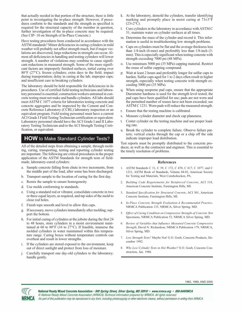
HOW to Make Standard Cylinder Tests?
References
that actually needed in that portion of the structure, there is littlepoint in investigating the in-place strength. However, if proce-dures conform to the standards and the strength as specified isrequired for the structural capacity of the member in question,further investigation of the in-place concrete may be required.(See CIP- 10 on Strength of In-Place Concrete.)
Have testing procedures been conducted in accordance with theASTM standards? Minor deficiencies in curing cylinders in mildweather will probably not affect strength much, but if major vio-lations are discovered, large reductions in strength can occur. Al-most all deficiencies in handling and testing cylinders will lowerstrength. A number of violations may combine to cause signifi-cant reductions in measured strength. Some of the more signifi-cant factors are improperly finished surfaces, initial curing over80°F (27°C); frozen cylinders; extra days in the field; impactduring transportation; delay in curing at the lab; improper caps;and insufficient care in breaking cylinders.
The laboratory should be held responsible for deficiencies in itsprocedures. Use of certified field-testing technicians and labora-tory personnel is essential; construction workers untrained in con-crete testing must not make and handle cylinders. All labs shouldmeet ASTM C 1077 criteria for laboratories testing concrete andconcrete aggregates and be inspected by the Cement and Con-crete Reference Laboratory (CCRL) laboratory inspection or anequivalent program. Field testing personnel must have a currentACI Grade I Field Testing Technician certification or equivalent.Laboratory personnel should have the ACI Grade I and II Labo-ratory Testing Technician and/or the ACI Strength Testing Certi-fication, or equivalent.
All of the detailed steps from obtaining a sample, through mold-ing, curing, transporting, testing and reporting cylinder testingare important. The following are critical procedures in the properapplication of the ASTM Standards for strength tests of field-made, laboratory-cured cylinders:
a. Sample concrete falling from chute in two increments, fromthe middle part of the load, after some has been discharged.
b. Transport sample to the location of curing for the first day.
c. Remix the sample to ensure homogeneity.
d. Use molds conforming to standards.
e. Using a standard rod or vibrator, consolidate concrete in twoor three equal layers, as required, and tap sides of the mold toclose rod holes.
f. Finish tops smooth and level to allow thin caps.
g. If necessary, move cylinders immediately after molding; sup-port the bottom.
h. For initial curing of cylinders at the jobsite during the first 24to 48 hours, store cylinders in a moist environment main-tained at 60 to 80°F (16 to 27°C). If feasible, immerse themolded cylinders in water maintained within this tempera-ture range. Curing boxes without temperature controls canoverheat and result in lower strengths.
i. If the cylinders are stored exposed to the environment, keepout of direct sunlight and protect from loss of moisture.
j. Carefully transport one day-old cylinders to the laboratory;handle gently.
k. At the laboratory, demold the cylinders, transfer identifyingmarking and promptly place in moist curing at 73±3°F(23±2°C).
l. Cure cylinders in the laboratory in accordance with ASTM C31; maintain water on cylinder surfaces at all times.
m. Determine the mass of the cylinder and record it. This infor-mation is useful in troubleshooting low strength problems.
n. Caps on cylinders must be flat and the average thickness lessthan 1/4-inch (6-mm) and preferably less than 1/8-inch (3-mm). This is especially significant when testing concrete withstrength exceeding 7000 psi (48 MPa).
o. Use minimum 5000 psi (35 MPa) capping material. Restrictthe reuse of sulfur capping compound.
p. Wait at least 2 hours and preferably longer for sulfur caps toharden. Sulfur caps aged for 1 to 2 days often result in higherstrength, especially when testing concrete with strength ex-ceeding 5000 psi (35 MPa).
q. When using neoprene pad caps, ensure that the appropriateDurometer hardness is used for the strength level tested; thepad caps have been qualified for use; pads are not worn andthe permitted number of reuses have not been exceeded; seeASTM C 1231. Worn pads will reduce the measured strength.
r. Ensure that the testing machine is calibrated.
s. Measure cylinder diameter and check cap planeness.
t. Center cylinder on the testing machine and use proper load-ing rate.
u. Break the cylinder to complete failure. Observe failure pat-tern; vertical cracks through the cap or a chip off the sideindicate improper load distribution.
Test reports must be promptly distributed to the concrete pro-ducer, as well as the contractor and engineer. This is essential tothe timely resolution of problems.
1. ASTM Standards C 31, C 39, C 172, C 470, C 617, C 1077, and C
1231, ASTM Book of Standards, Volume 04.02, American Society
for Testing and Materials, West Conshohocken, PA.
2. Building Code Requirements for Reinforced Concrete, ACI 318,
American Concrete Institute, Farmington Hills, MI.
3. Standard Specification for Structural Concrete, ACI 301, American
Concrete Institute, Farmington Hills, MI.
4. In-Place Concrete Strength Evaluation-A Recommended Practice.
NRMCA Publication 133, NRMCA, Silver Spring, MD.
5. Effect of Curing Condition on Compressive Strength of Concrete Test
Specimens, NRMCA Publication 53, NRMCA Silver Spring, MD.
6. Review of Variables that Influence Measured Concrete Compressive
Strength, David N. Richardson, NRMCA Publication 179, NRMCA,
Silver Spring, MD.
7. Low Strength Tests? Maybe Not! E.O. Goeb, Concrete Products, De-
cember 1992.
8. Why Low Cylinder Tests in Hot Weather? E.O. Goeb, Concrete Con-
struction, Jan. 1986.

CIP 10 - Strength of In-Place Concrete
Concrete structures are designed to carry dead andlive loads during construction and in service. Samplesof concrete are obtained during construction and stan-dard ASTM procedures are used to measure the po-tential strength of the concrete as delivered. Cylin-ders are molded and cured at 60 to 80°F (17 to 27°C)for one day and then moist cured in the laboratoryuntil broken in compression, normally at an age of 7and 28 days. The in-place strength of concrete willnot be equivalent to that measured on standard cylin-ders. Job practices for handling, placing, consolida-tion, and curing concrete in structures are relied uponto provide an adequate percentage of that potentialstrength in the structure. Structural design principlesrecognize this and the ACI Building Code, ACI 318,has a process of assuring the structural safety of theconcrete construction.
Means of measuring, estimating or comparing thestrength of in-place concrete include: rebound ham-mer, penetration probe, pullouts, cast-in-place cylin-ders, tests of drilled cores, and load tests of the struc-tural element.
Cores drilled from the structure are one of the meansof evaluating whether the structural capacity of a con-crete member is adequate and ACI 318 provides someguidance on this evaluation. Drilled cores test lowerthan properly made and tested standard molded 6 x12 inch (150 x 300-mm) cylinders. This applies to allformed structural concrete. Exceptions may occur forcores from concrete cast against an absorptivesubgrade or cores from lean, low strength mass con-crete. The ACI Building Code recognizes that undercurrent design practices, concrete construction can beconsidered structurally adequate if the average of threecores from the questionable region is equal to or ex-ceeds 85 percent of specified strength, ƒ´c with nosingle core less than 75 percent of ƒ´c.
WHAT is the Strengthof In-Place Concrete?
WHY Measure In-Place Strength?
A - Penetration
Resistance Test
(ASTM C 803)
B - Rebound Test
(ASTM C 805)
C - Core Test
(ASTM C 42)
A B
Tests of in-place concrete may be needed when stan-
dard cylinder strengths are low and not in compliancewith the specification as outlined in ACI 318. How-ever, do not investigate in-place without first check-ing to be sure that: the concrete strengths actually failedto meet the specification provisions, low strengths arenot attributable to faulty testing practices, or the speci-fied strength is really needed. (See CIP-9 on Low Con-crete Cylinder Strength) In many cases, the concretecan be accepted for the intended use without in-placestrength testing.
There are many other situations that may require theinvestigation of in-place strength. These include: shoreand form removal, post-tensioning, or early load ap-plication; investigation of damage due to freezing, fire,or adverse curing exposure; evaluation of older struc-tures; and when a lower design strength concrete isplaced in a member by mistake. When cores or otherin-place tests fail to assure structural adequacy, addi-tional curing of the structure may provide the neces-sary strength. This is particularly possible with con-crete containing slow strength-gaining cement, fly ash,or slag.

1982, 1989 AND 2000
HOW to Make Standard Cylinder Tests?
References
1. In-Place Methods to Estimate Concrete Strength, ACI 228.1R,
American Concrete Institute, Farmington Hills, MI.
2. Nondestructive Tests, V.M. Malhotra, Chapter 30 in ASTM
STP 169C, American Society for Testing and Materials, West
Conshohocken, PA.
3. Guide to Nondestructive Testing of Concrete, G.I. Crawford,
Report FHWA-SA-97-105, Sept. 1997, Federal Highway Ad-
ministration, Washington, DC.
4. In-Place Strength Evaluation - A Recommended Practice,
NRMCA Publication 133, NRMCA, Silver Spring, MD.
5. Understanding Concrete Core Testing, Bruce A. Suprenant,
NRMCA Publication 185, NRMCA, Silver Spring, MD.
6. ASTM C 31, C 39, C 42, C 805, C 803, C 873, C 900, ASTM
Book of Standards, Vol. 04.02, American Society for Testing
and Materials, West Conshohocken, PA
7. Building Code Requirements for Structural Concrete, ACI 318,
American Concrete Institute, Farmington Hills, MI.
If only one set of cylinders is low, often the questioncan be settled by comparing rebound hammer or proberesults on concrete in areas represented by acceptablecylinder results. Where the possibility of low strengthis such that large portions need to be investigated, awell-organized study will be needed. Establish a gridand obtain systematic readings including good andquestionable areas. Tabulate the hammer or probe read-ings. If areas appear to be low, drill cores from bothlow and high areas. If the cores confirm the hammeror probe results, the need for extensive core tests isgreatly reduced.
Core Strength, ASTM C 42 - If core drilling is nec-essary observe these precautions:
a. Test a minimum of 3 cores for each section of ques-tionable concrete;
b. Obtain 31/2 in. (85 mm) minimum diameter cores.Obtain larger cores for concrete with over 1 in. (25.0mm) size aggregate;
c. Try to obtain a length at least 11/2 times the diam-eter (L/D ratio);
d. Trim to remove steel provided the minimum 11/2 L/D ratio can be maintained;
e. Trim ends square with an automatic feed diamondsaw;
f. When testing, keep cap thickness under 1/8 in. (3mm);
g. Use high strength capping material; neoprene padcaps should not be used;
h. Check planeness of caps and bearing blocks;
i. Do not drill cores from the top layers of columns,slabs, walls, or footings, which will be 10 to 20percent weaker than cores from the mid or lowerportions; and
j. Test cores after drying for 7 days if the structure isdry in service; otherwise soak cores 40 hours priorto testing. Review the recommendations for condi-tioning cores in current versions of ACI 318 andASTM C 42.
Probe Penetration Resistance, ASTM C 803 - Probesdriven into concrete can be used to study variations inconcrete quality:
a. Different size probes or a change in driving forcemay be necessary for large differences in strengthor unit weight;
b. Accurate measurement of the exposed length of theprobe is required;
c. Probes should be spaced at least 7 in. apart and notbe close to the edge of the concrete;
d. Probes not firmly embedded in the concrete shouldbe rejected; and
e. Develop a strength calibration curve for the mate-rials and conditions under investigation.
Rebound Hammer, ASTM C 805 - Observe theseprecautions:
a. Wet all surfaces for several hours or overnight be-cause drying affects rebound number;
b. Don’t compare readings on concrete cast againstdifferent form materials, concrete of varying mois-ture content, readings from different impact direc-tions, on members of different mass, or results us-ing different hammers;
c. Don’t grind off the surface unless it is soft, fin-ished or textured;
d. Test structural slabs from the bottom; and
e. Do not test frozen concrete.
Advance Planning - When it is known in advancethat in-place testing is required, such as for shore andform removal, other methods can be considered suchas: cast-in-place, push-out cylinders and pulloutstrength measuring techniques covered by ASTM C873 and C 900.

CIP 11 - Curing In-Place Concrete
WHAT is Curing?
WHY Cure?
Application of liquid membrane-forming compound
with hand sprayer.
Slab on grade covered with waterproof paper
for curing.
Curing is the maintaining of an adequate moisture content and
temperature in concrete at early ages so that it can develop prop-
erties the mixture was designed to achieve. Curing begins immedi-
ately after placement and finishing so that the concrete may de-
velop the desired strength and durability.
Without an adequate supply of moisture, the cementitious materi-
als in concrete cannot react to form a quality product. Drying may
remove the water needed for this chemical reaction called hydra-
tion and the concrete will not achieve its potential properties.
Temperature is an important factor in proper curing, since the rate
of hydration, and therefore, strength development, is faster at higher
temperatures. Generally, concrete temperature should be maintained
above 50°F (10°C) for an adequate rate of strength development.
Further, a uniform temperature should be maintained through theconcrete section while it is gaining strength to avoid thermal crack-
ing.
For exposed concrete, relative humidity and wind conditions are
also important; they contribute to the rate of moisture loss from theconcrete and could result in cracking, poor surface quality and du-
rability. Protective measures to control evaporation of moisture from
concrete surfaces before it sets are essential to prevent plastic shrink-
age cracking (See CIP 5).
Several important reasons are:
a. Predictable strength gain. Laboratory tests show that con-
crete in a dry environment can lose as much as 50 percent of its
potential strength compared to similar concrete that is moistcured. Concrete placed under high temperature conditions will
gain early strength quickly but later strengths may be reduced.
Concrete placed in cold weather will take longer to gain strength,
delaying form removal and subsequent construction.
b. Improved durability. Well-cured concrete has better surface
hardness and will better withstand surface wear and abrasion.
Curing also makes concrete more watertight, which prevents
moisture and water-borne chemicals from entering into the con-
crete, thereby increasing durability and service life.
c. Better serviceability and appearance. A concrete slab that
has been allowed to dry out too early will have a soft surface
with poor resistance to wear and abrasion. Proper curing re-duces crazing, dusting and scaling.
HOW to Cure?
Moisture Requirements for Curing - Concrete should be pro-
tected from losing moisture until final finishing using suitable meth-ods like wind breaks, fogger sprays or misters to avoid plastic shrink-
age cracking. After final finishing the concrete surface must be kept
continuously wet or sealed to prevent evaporation for a period of at
least several days after finishing. See the table for examples.
Systems to keep concrete wet include:
a. Burlap or cotton mats and rugs used with a soaker hose or sprin-
kler. Care must be taken not to let the coverings dry out and
absorb water from the concrete. The edges should be lappedand the materials weighted down so they are not blown away.

1982, 1989 AND 2000
References
1. Effect of Curing Condition on Compressive Strength of Con-crete Test Specimens, NRMCA Publication No. 53, NationalReady Mixed Concrete Association, Silver Spring, MD.
2. How to Eliminate Scaling, Concrete International, February1980. American Concrete Institute, Farmington Hills, MI.
3. ASTM C 309, Specification for Liquid Membrane FormingCompounds for Curing Concrete, American Society for Test-ing Materials, West Conshohocken, PA.
4. ASTM C 171, Specification for Sheet Materials for CuringConcrete, American Society for Testing Materials, WestConshohocken, PA.
5. Standard Practice for Curing Concrete, ACI 308, AmericanConcrete Institute, Farmington Hills, MI.
6. Standard Specification for Curing Concrete, ACI 308.1, Ameri-can Concrete Institute, Farmington Hills, MI.
7. Cold Weather Concreting, ACI 306R, American Concrete In-stitute, Farmington Hills, MI.
b. Straw that is sprinkled with water regularly. Straw can easilyblow away and, if it dries, can catch fire. The layer of straw
should be 6 inches thick, and should be covered with a tarp.
c. Damp earth, sand, or sawdust can be used to cure flatwork,especially floors. There should be no organic or iron-staining
contaminants in the materials used.
d. Sprinkling on a continuous basis is suitable provided the airtemperature is well above freezing. The concrete should not be
allowed to dry out between soakings, since alternate wetting
and drying is not an acceptable curing practice.
e. Ponding of water on a slab is an excellent method of curing.
The water should not be more than 20°F (11°C) cooler than the
concrete and the dike around the pond must be secure against
leaks.
Moisture retaining materials include:
a. Liquid membrane-forming curing compounds must conform
to ASTM C 309. Apply to the concrete surface about one hourafter finishing. Do not apply to concrete that is still bleeding or
has a visible water sheen on the surface. While a clear liquid
may be used, a white pigment will provide reflective properties
and allow for a visual inspection of coverage. A single coat may
be adequate, but where possible a second coat, applied at right
angles to the first, is desirable for even coverage. If the concretewill be painted, or covered with vinyl or ceramic tile, then a
liquid compound that is non-reactive with the paint or adhe-
sives must be used, or use a compound that is easily brushed or
washed off. On floors, the surface should be protected from the
other trades with scuff-proof paper after the application of the
curing compound.
b. Plastic sheets - either clear, white (reflective) or pigmented.
Plastic should conform to ASTM C 171, be at least 4 mils thick,
and preferably reinforced with glass fibers. Dark colored sheetsare recommended when ambient temperatures are below 60°F
(15°C) and reflective sheets should be used when temperatures
exceed 85°F (30°C). The plastic should be laid in direct contact
with the concrete surface as soon as possible without marring
the surface. The edges of the sheets should overlap and be fas-
tened with waterproof tape and then weighted down to preventthe wind from getting under the plastic. Plastic can make dark
streaks wherever a wrinkle touches the concrete, so plastic should
not be used on concretes where appearance is important. Plas-
tic is sometimes used over wet burlap to retain moisture.
c. Waterproof paper - used like plastic sheeting, but does not mar
the surface. This paper generally consists of two layers of kraft
paper cemented together and reinforced with fiber. The paper
should conform to ASTM C 171.
Note that products sold as evaporation retardants are used to reduce
the rate of evaporation from fresh concrete surfaces before it sets to
prevent plastic shrinkage cracking. These materials should not be
used for final curing.
Example Minimum Curing Period
to Achieve 50% of Specified Strength*
Type I Type II Type III
Cement Cement Cement
Temperature—50°F (10°C)
6 days 9 days 3 days
Temperature—70°F (21°C)
4 days 6 days 3 days
*Values are approximate and based on cylinder
strength tests. Specific values can be established for
specific materials and mixtures. From Ref. 7.
Control of temperature:
In cold weather do not allow concrete to cool faster than a rate of
5°F (3°C) per hour for the first 24 hours. Concrete should be pro-
tected from freezing until it reaches a compressive strength of atleast 500 psi (3.5 MPa) using insulating materials. Curing methods
that retain moisture, rather than wet curing, should be used when
freezing temperatures are anticipated. Guard against rapid tempera-
ture changes after removing protective measures. Guidelines are
provided in Reference 7.
In hot weather, higher initial curing temperature will result in rapid
strength gain and lower ultimate strengths. Water curing and sprin-
kling can be used to achieve lower curing temperatures in summer.
Day and night temperature extremes that allow cooling faster than
5°F (3°C) per hour during the first 24 hours should be protectedagainst.

CIP 12 - Hot Weather Concreting
WHAT is Hot Weather?
WHY Consider Hot Weather?
Curing is the maintaining of an adequate moisture content and
temperature in concrete at early ages so that it can develop prop-
erties the mixture was designed to achieve. Curing begins immedi-
ately after placement and finishing so that the concrete may de-
velop the desired strength and durability.
Without an adequate supply of moisture, the cementitious materi-
als in concrete cannot react to form a quality product. Drying may
remove the water needed for this chemical reaction called hydra-
tion and the concrete will not achieve its potential properties.
Temperature is an important factor in proper curing, since the rate
of hydration, and therefore, strength development, is faster at higher
temperatures. Generally, concrete temperature should be maintained
above 50°F (10°C) for an adequate rate of strength development.
Further, a uniform temperature should be maintained through theconcrete section while it is gaining strength to avoid thermal crack-
ing.
For exposed concrete, relative humidity and wind conditions are
also important; they contribute to the rate of moisture loss from theconcrete and could result in cracking, poor surface quality and du-
rability. Protective measures to control evaporation of moisture from
concrete surfaces before it sets are essential to prevent plastic shrink-
age cracking (See CIP 5).
Several important reasons are:
a. Predictable strength gain. Laboratory tests show that con-
crete in a dry environment can lose as much as 50 percent of its
potential strength compared to similar concrete that is moistcured. Concrete placed under high temperature conditions will
gain early strength quickly but later strengths may be reduced.
Concrete placed in cold weather will take longer to gain strength,
delaying form removal and subsequent construction.
b. Improved durability. Well-cured concrete has better surface
hardness and will better withstand surface wear and abrasion.
Curing also makes concrete more watertight, which prevents
moisture and water-borne chemicals from entering into the con-
crete, thereby increasing durability and service life.
c. Better serviceability and appearance. A concrete slab that
has been allowed to dry out too early will have a soft surface
with poor resistance to wear and abrasion. Proper curing re-duces crazing, dusting and scaling.
HOW to Cure?
Moisture Requirements for Curing - Concrete should be pro-tected from losing moisture until final finishing using suitable meth-
ods like wind breaks, fogger sprays or misters to avoid plastic shrink-
age cracking. After final finishing the concrete surface must be kept
continuously wet or sealed to prevent evaporation for a period of at
least several days after finishing. See the table for examples.
Systems to keep concrete wet include:
a. Burlap or cotton mats and rugs used with a soaker hose or sprin-
kler. Care must be taken not to let the coverings dry out andabsorb water from the concrete. The edges should be lapped
and the materials weighted down so they are not blown away.
b. Straw that is sprinkled with water regularly. Straw can easilyblow away and, if it dries, can catch fire. The layer of straw
should be 6 inches thick, and should be covered with a tarp.
Effect of temperature on water requirement of concrete (Ref 1)
Effect of temperature on concrete setting time (Ref 1)

1982, 1989 AND 2000
References
1. Effect of Curing Condition on Compressive Strength of Con-crete Test Specimens, NRMCA Publication No. 53, NationalReady Mixed Concrete Association, Silver Spring, MD.
2. How to Eliminate Scaling, Concrete International, February1980. American Concrete Institute, Farmington Hills, MI.
3. ASTM C 309, Specification for Liquid Membrane FormingCompounds for Curing Concrete, American Society for Test-ing Materials, West Conshohocken, PA.
4. ASTM C 171, Specification for Sheet Materials for CuringConcrete, American Society for Testing Materials, WestConshohocken, PA.
5. Standard Practice for Curing Concrete, ACI 308, AmericanConcrete Institute, Farmington Hills, MI.
6. Standard Specification for Curing Concrete, ACI 308.1, Ameri-can Concrete Institute, Farmington Hills, MI.
7. Cold Weather Concreting, ACI 306R, American Concrete In-stitute, Farmington Hills, MI.
c. Damp earth, sand, or sawdust can be used to cure flatwork,especially floors. There should be no organic or iron-staining
contaminants in the materials used.
d. Sprinkling on a continuous basis is suitable provided the airtemperature is well above freezing. The concrete should not be
allowed to dry out between soakings, since alternate wetting
and drying is not an acceptable curing practice.
e. Ponding of water on a slab is an excellent method of curing.
The water should not be more than 20°F (11°C) cooler than the
concrete and the dike around the pond must be secure against
leaks.
Moisture retaining materials include:
a. Liquid membrane-forming curing compounds must conform
to ASTM C 309. Apply to the concrete surface about one hourafter finishing. Do not apply to concrete that is still bleeding or
has a visible water sheen on the surface. While a clear liquid
may be used, a white pigment will provide reflective properties
and allow for a visual inspection of coverage. A single coat may
be adequate, but where possible a second coat, applied at right
angles to the first, is desirable for even coverage. If the concretewill be painted, or covered with vinyl or ceramic tile, then a
liquid compound that is non-reactive with the paint or adhe-
sives must be used, or use a compound that is easily brushed or
washed off. On floors, the surface should be protected from the
other trades with scuff-proof paper after the application of the
curing compound.
b. Plastic sheets - either clear, white (reflective) or pigmented.
Plastic should conform to ASTM C 171, be at least 4 mils thick,
and preferably reinforced with glass fibers. Dark colored sheetsare recommended when ambient temperatures are below 60°F
(15°C) and reflective sheets should be used when temperatures
exceed 85°F (30°C). The plastic should be laid in direct contact
with the concrete surface as soon as possible without marring
the surface. The edges of the sheets should overlap and be fas-
tened with waterproof tape and then weighted down to preventthe wind from getting under the plastic. Plastic can make dark
streaks wherever a wrinkle touches the concrete, so plastic should
not be used on concretes where appearance is important. Plas-
tic is sometimes used over wet burlap to retain moisture.
c. Waterproof paper - used like plastic sheeting, but does not mar
the surface. This paper generally consists of two layers of kraft
paper cemented together and reinforced with fiber. The paper
should conform to ASTM C 171.
Note that products sold as evaporation retardants are used to reduce
the rate of evaporation from fresh concrete surfaces before it sets to
prevent plastic shrinkage cracking. These materials should not be
used for final curing.
Example Minimum Curing Period
to Achieve 50% of Specified Strength*
Type I Type II Type III
Cement Cement Cement
Temperature—50°F (10°C)
6 days 9 days 3 days
Temperature—70°F (21°C)
4 days 6 days 3 days
*Values are approximate and based on cylinder
strength tests. Specific values can be established for
specific materials and mixtures. From Ref. 7.
Control of temperature:
In cold weather do not allow concrete to cool faster than a rate of
5°F (3°C) per hour for the first 24 hours. Concrete should be pro-
tected from freezing until it reaches a compressive strength of at
least 500 psi (3.5 MPa) using insulating materials. Curing methods
that retain moisture, rather than wet curing, should be used when
freezing temperatures are anticipated. Guard against rapid tempera-ture changes after removing protective measures. Guidelines are
provided in Reference 7.
In hot weather, higher initial curing temperature will result in rapid
strength gain and lower ultimate strengths. Water curing and sprin-kling can be used to achieve lower curing temperatures in summer.
Day and night temperature extremes that allow cooling faster than
5°F (3°C) per hour during the first 24 hours should be protected
against.

CIP 13 - Concrete Blisters
WHAT are Blisters?
WHY do Blisters Form?
Blisters are hollow, low-profile bumps on the con-
crete surface, typically from the size of a dime up to
1 inch (25 mm), but occasionally even 2 or 3 inches
(50 – 75 mm) in diameter. A dense troweled skin of
mortar about 1/8in. (3 mm) thick covers an underly-
ing void that moves around under the surface during
troweling. Blisters may occur shortly after the
completion of finishing operation. In poorly lighted
areas, small blisters may be difficult to see during
finishing and may not be detected until they break
under traffic.
Blisters may form on the surface of fresh concrete
when either bubbles of entrapped air or bleed water
migrate through the concrete and become trapped
under the surface, which has been sealed prematurely
during the finishing operations. These defects are
not easily repaired after concrete hardens.
Blisters are more likely to form if:
1. Insufficient or excessive vibration is employed.
Insufficient vibration prevents the entrapped air
from being released and excessive use of vibrat-
ing screeds works up a thick mortar layer on the
surface.
2. An improper tool is used for floating the surface
or it is used improperly. The surface should be
tested to determine which tool, whether it be
wood or magnesium bull float, does not seal the
surface. The floating tool should be kept as flat
as possible.
3. Excessive evaporation of bleed water occurs and
the concrete appears ready for final finishing op-
erations (premature finishing), when, in fact, the
underlying concrete is still releasing bleed water
and entrapped air. High rate of bleed water evapo-
ration is especially a problem during periods of
DENSE TROWELED SURFACE
AIR AND BLEED WATER
Concrete Blister
high ambient temperatures, high winds and/or low
humidity.
4. Entrained air is used or is higher than normal.
Rate of bleeding and quantity of bleed water is
greatly reduced in air-entrained concrete giving
the appearance that the concrete is ready to float
and further finish causing premature finishing.
5. The subgrade is cooler than concrete. The top
surface sets faster than the concrete in the bot-
tom and the surface appears ready to be floated
and further finished.
6. The slab is thick and it takes a longer time for the
entrapped air and bleed water to rise to the sur-
face.
7. The concrete is cohesive or sticky from higher
content of cementitious materials or excessive
fines in the sand. These mixtures also bleed less

1983, 2001, 2005
HOW To Prevent Blisters?
The finisher should be wary of a concrete surface that
appears to be ready for final finishing before it would
normally be expected. Emphasis in finishing opera-
tions should be on placing, striking off and bull float-
ing the concrete as rapidly as possible and without
working up a layer of mortar on the surface. After
these operations are completed, further finishing
should be delayed as long as possible and the surface
covered with polyethylene or otherwise protected from
evaporation. If conditions for high evaporation rates
exist, place a cover on a small portion of the slab to
judge if the concrete is still bleeding. In initial float-
ing, the float blades should be flat to avoid densifying
the surface too early. Use of an accelerating admix-
ture or heated concrete often prevents blisters in cool
weather. It is recommended that non-air entrained
concrete be used in interior slabs and that air entrained
concrete not be steel troweled.
If blisters are forming, try to either flatten the trowel
blades or tear the surface with a wood float and delay
finishing as long as possible. Under conditions caus-
ing rapid evaporation, slow evaporation by using wind
breaks, water misting of the surface, evaporation re-
tarders, or a cover (polyethylene film or wet burlap)
and at a slower rate. Concrete mixtures with lower
contents of cementitious materials bleed rapidly
for a shorter period, have higher total bleeding
and tend to delay finishing.
8. A dry shake is prematurely applied, particularly
over air-entrained concrete.
9. The slab is placed directly on top of a vapor re-
tarder or an impervious base, preventing bleed
water from being absorbed by the subgrade.
References
1. Guide for Concrete Floor and Slab Construction, ACI
302.1R, American Concrete Institute, Farmington Hills,
MI. www.concrete.org
2. Slabs on Grade, ACI Concrete Craftsman Series, CCS
1, American Concrete Institute, Farmington Hills, MI.
3. Hot weather Concreting, ACI 305R, American Con
crete Institute, Farmington Hills, MI.
4. Concrete Slab Surface Defects: Causes,
Prevention,Repair, IS 177, Portland Cement Associa
tion, Skokie, IL. www.cement.org
5. Concrete Surface Blistering—Causes and Cures, Carl
O. Peterson, Concrete Construction, September 1970.
www.concreteconstruction.net
6. CIP 14 - Finishing Concrete Flatwork; CIP 20 -
Delamination of Troweled Concrete Surfaces, NRMCA
CIP Series. www.nrmca.org.
7. Finishing, Concrete Construction, August 1976, p. 369.
8. Finishing Problems and Surface Defects in Flatwork,
Concrete Construction, April 1979.
Follow These Rules to Avoid Blisters
1. Do not seal surface before air or bleed water from below have had a chance to escape.
2. Avoid dry shakes on air-entrained concrete.
3. Use heated or accelerated concrete to promote even setting throughout the depth of the slab in cooler
weather.
4. Do not place slabs directly on vapor retarders. If vapor retarders are essential (CIP 28) take steps to
avoid premature finishing.
5. Protect surface from premature drying and evaporation.
6. Do not use a jitterbug or excessive vibration such as a vibratory screed on slumps over 5 inches (125
mm).
7. Air entrained concrete should not be steel troweled. If required by specifications, extreme caution
should be exercised when timing the finishing operation.
between finishing operations. Further recommenda-
tions are given in ACI 302.1R and ACI 305.
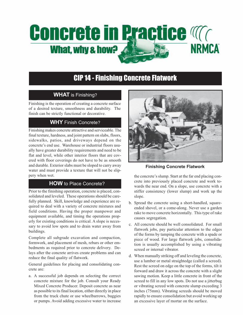
CIP 14 - Finishing Concrete Flatwork
WHAT is Finishing?
HOW to Place Concrete?
Finishing is the operation of creating a concrete surface
of a desired texture, smoothness and durability. The
finish can be strictly functional or decorative.
Finishing Concrete Flatwork
WHY Finish Concrete?
Finishing makes concrete attractive and serviceable. The
final texture, hardness, and joint pattern on slabs, floors,
sidewalks, patios, and driveways depend on the
concrete’s end use. Warehouse or industrial floors usu-
ally have greater durability requirements and need to be
flat and level, while other interior floors that are cov-
ered with floor coverings do not have to be as smooth
and durable. Exterior slabs must be sloped to carry away
water and must provide a texture that will not be slip-
pery when wet.
Prior to the finishing operation, concrete is placed, con-
solidated and leveled. These operations should be care-
fully planned. Skill, knowledge and experience are re-
quired to deal with a variety of concrete mixtures and
field conditions. Having the proper manpower and
equipment available, and timing the operations prop-
erly for existing conditions is critical. A slope is neces-
sary to avoid low spots and to drain water away from
buildings.
Complete all subgrade excavation and compaction,
formwork, and placement of mesh, rebars or other em-
bedments as required prior to concrete delivery. De-
lays after the concrete arrives create problems and can
reduce the final quality of flatwork.
General guidelines for placing and consolidating con-
crete are:
a. A successful job depends on selecting the correct
concrete mixture for the job. Consult your Ready
Mixed Concrete Producer. Deposit concrete as near
as possible to its final location, either directly in place
from the truck chute or use wheelbarrows, buggies
or pumps. Avoid adding excessive water to increase
the concrete’s slump. Start at the far end placing con-
crete into previously placed concrete and work to-
wards the near end. On a slope, use concrete with a
stiffer consistency (lower slump) and work up the
slope.
b. Spread the concrete using a short-handled, square-
ended shovel, or a come-along. Never use a garden
rake to move concrete horizontally. This type of rake
causes segregation.
c. All concrete should be well consolidated. For small
flatwork jobs, pay particular attention to the edges
of the forms by tamping the concrete with a spade or
piece of wood. For large flatwork jobs, consolida-
tion is usually accomplished by using a vibrating
screed or internal vibrator.
d. When manually striking off and leveling the concrete,
use a lumber or metal straightedge (called a screed).
Rest the screed on edge on the top of the forms, tilt it
forward and draw it across the concrete with a slight
sawing motion. Keep a little concrete in front of the
screed to fill in any low spots. Do not use a jitterbug
or vibrating screed with concrete slump exceeding 3
inches (75mm). Vibrating screeds should be moved
rapidly to ensure consolidation but avoid working up
an excessive layer of mortar on the surface.

1986, 1990, 2001
1. LEVEL the concrete further using a bull float, darby, or
highway straightedge as soon as it has been struck-off. This
operation should be completed before bleed water appears
on the surface. The bull float or darby embeds large aggre-
gate, smoothes the surface, and takes out high and low spots.
Keep the bull float as flat as possible to avoid premature
sealing of the surface.
2. WAIT for the concrete to stop “bleeding”. All other finish-
ing operations must wait until the concrete has stopped
bleeding and the water sheen has left the surface. Any fin-
ishing operations done while the concrete is still bleeding
will result in later problems, such as dusting, scaling, craz-
ing, delamination and blisters. The waiting period depends
on the setting and bleeding characteristics of the concrete
and the ambient conditions. During the waiting period, pro-
tect against evaporation from the concrete surface if condi-
tions are hot, dry and windy. Cover a small test portion of
the slab to evaluate if the concrete is still bleeding. General
guidance regarding whether the concrete has sufficiently set
for final finishing operations is when a footprint indentation
of a person standing on the slab is between 1/8 to ¼ inch (3
to 6 mm).
3. EDGE the concrete when required. Spade the concrete to
break any bond with the form with a small mason’s trowel.
Use the edging tool to obtain durable rounded edges.
4. JOINT the concrete when required. The jointing tool should
have a blade one-fourth the depth of the slab. Use a straight
piece of lumber as a guide. A shallow-bit groover should
only be used for decorative grooves. When saw-cutting is
required, it should be done as soon as the concrete is hard
enough not to be torn by the blade. Early entry saw cutting
can be done before the concrete has completely hardened.
See CIP 6 for jointing practices and spacing.
5. FLOAT the concrete by hand or machine in order to embed
the larger aggregates. Floating also levels and prepares the
surface for further finishing. Never float the concrete while
there is still bleed water on the surface.
6. TROWEL the concrete when required for its end use. For
sidewalks, patios , driveways and other exterior applications,
troweling is not usually required. Air entrained concrete
should not be troweled. If trowel finishing of air-entrained
concrete is required by specifications, extreme caution should
be exercised when timing the finishing operation. For a
smooth floor make successive passes with a smaller steel
trowel and increased pressure. Repeated passes with a steel
trowel will produce a smooth floor that will be slippery when
wet. Excessive troweling may create dark “trowel burns.”
Improperly tilting the trowel will cause an undesirable “chat-
ter” texture.
7. TEXTURE the concrete surface as required after floating
or troweling. For exterior concrete flatwork (sidewalks, pa-
tios or driveways) texture the concrete surface after the float-
ing operation with a coarse or fine push-broom to give a
non-slip surface. For interior flatwork texture the concrete
surface after final troweling. Concrete can be finished with
several decorative treatments, such as exposed aggregate,
dry shake color, integral color, and stamped or patterned
concrete. Decorative finishes need much more care and ex-
perience.
8. NEVER sprinkle water or cement on concrete while finish-
ing it. This may cause dusting or scaling.
9. CURE the concrete as soon as all finishing is completed to
provide proper conditions for cement hydration, which pro-
vides the required strength and durability to the concrete
surface. In severe conditions slab protection may be needed
even before finishing is complete. See CIP 11 for more in-
formation on curing concrete.
10. AVOID concrete burns to skin by following proper safety
practices.
Follow These Rules to Finish Concrete
1. Place and move concrete to its final location using procedures that avoid segregation.
2. Strike off and obtain an initial level surface without sealing the surface.
3. Wait until the bleed water disappears from the surface before starting finishing operations.
4. Use the appropriate surface texture as required for the application.
5. Avoid steel troweling air-entrained concrete.
6. Cure the concrete to ensure it achieves the desired strength and durability.
1. Concrete in Practice (CIP) Series, National Ready Mixed
Concrete Association, Silver Spring, Maryland.
www.nrmca.org
2. Guide for Concrete Floor and Slab Construction, ACI 302.1R,
American Concrete Institute, Farmington Hills, MI.
www.concrete.org.
3. Slabs on Grade, ACI Concrete Craftsman Series, CCS-1,
American Concrete Institute, Farmington Hills, MI.
4. Cement Mason’s Guide, PA122, Portland Cement Associa-
tion, Skokie, IL. www.cement.org.
5. Residential Concrete, National Association of Home Build-
ers, Washington, D.C.
6. Sealing Effects of Finishing Tools, Bruce Suprenant, Con-
crete Construction, September 1999.
www.concreteconstruction.net.
7. Finishing Tool Primer, Kim Basham, Concrete Construction,
July 2000.
References
HOW to Finish Concrete?

CIP 15 - Chemical Admixtures for Concrete
WHAT are Admixtures? HOW to Use Admixtures?
Admixtures are natural or manufactured chemicals which
are added to the concrete before or during mixing. The most
often used admixtures are air-entraining agents, water re-
ducers, water-reducing retarders and accelerators.
WHY Use Admixtures?
Admixtures are used to give special properties to fresh or
hardened concrete. Admixtures may enhance the durability,
workability or strength characteristics of a given concrete
mixture. Admixtures are used to overcome difficult con-
struction situations, such as hot or cold weather placements,
pumping requirements, early strength requirements, or very
low water-cement ratio specifications.
Chemical Admixtures for Concrete
L to R: HRWR, Air-Entraining Agent, Retarder
Relative quantities for one cu.yd.
Consult your ready mixed concrete supplier about which
admixture(s) may be appropriate for your application. Ad-
mixtures are evaluated for compatibility with cementitious
materials, construction practices, job specifications and
economic benefits before being used.
Follow This Guide to Use Admixtures
1. AIR-ENTRAINING ADMIXTURESare liquid chemi-
cals added during batching concrete to produce mi-
croscopic air bubbles, called entrained air, when
concrete is mixed. These air bubbles improve the
concrete’s resistance to damage caused by freez-
ing and thawing and deicing salt application. In plas-
tic concrete entrained air improves workability and
may reduce bleeding and segregation of concrete
mixtures. For exterior flatwork (parking lots, drive-
ways, sidewalks, pool decks, patios) that is subject
to freezing and thawing weather cycles, or in areas
where deicer salts are used, specify a normal air
content of 4% to 7% of the concrete volume de-
pending on the size of coarse aggregate (see Table
on next page). Air entrainment is not necessary for
interior structural concrete since it is not subject to
freezing and thawing. It should be avoided for con-
crete flatwork that will have a smooth troweled fin-
ish. In high cement content concretes, entrained
air will reduce strength by about 5% for each 1% of
air added; but in low cement content concretes,
adding air has less effect and may even cause a
modest increased strength due to the reduced wa-
ter demand for required slump. Air entraining ad-
mixtures for use in concrete should meet the re-
quirements of ASTM C 260, Specification for Air-
Entraining Admixtures for Concrete.
2. WATER REDUCERS are used for two different pur-
poses: (1) to lower the water content in plastic con-
crete and increase its strength; (2) to obtain higher
slump without adding water. Water-reducers will
generally reduce the required water content of a
concrete mixture for a given slump. These admix-
tures disperse the cement particles in concrete and
make more efficient use of cement. This increases
strength or allows the cement content to be reduced
while maintaining the same strength. Water-reduc-

1987,1989, 2001
Besides these standard types of admixtures, there are products avail-
able for enhancing concrete properties for a wide variety of applica-
tions. Some of these products include: Corrosion inhibitors, shrink-
age reducing admixtures, anti-washout admixtures, hydration stabi-
lizing or extended set retarding admixtures, admixtures to reduce
potential for alkali aggregate reactivity, pumping aids, damp-proof-
ing admixtures and a variety of colors and products that enhance the
aesthetics of concrete. Contact your local ready mixed concrete pro-
ducer for more information on specialty admixture products and the
benefits they provide to concrete properties.
ers are used to increase slump of concrete without adding
water and are useful for pumping concrete and in hot weather
to offset the increased water demand. Some water-reducers
may aggravate the rate of slump loss with time. Water-re-
ducers should meet the reuirements for Type A in ASTM C
494 Specification for Chemical Admixtures for Concrete.
Mid-range water reducers are now commonly used and they
have a greater ability to reduce the water content. These
admixtures are popular as they improve the finishability of
concrete flatwork. Mid-range water reducers must at least
meet the requirements for Type A in ASTM C 494 as they do
not have a separate classification in an admixture specifica-
tion.
3. RETARDERS are chemicals that delay the initial setting of
concrete by an hour or more. Retarders are often used in hot
weather to counter the rapid setting caused by high tem-
peratures. For large jobs, or in hot weather, specify concrete
with retarder to allow more time for placing and finishing.
Most retarders also function as water reducers. Retarders
should meet the requirements for Type B or D in ASTM C
494.
4. ACCELERATORS reduce the initial set time of concrete and
give higher early strength. Accelerators do not act as an an-
tifreeze; rather, they speed up the setting and rate of strength
gain, thereby making the concrete stronger to resist dam-
age from freezing in cold weather. Accelerators are also used
in fast track construction requiring early form removal, open-
ing to traffic or load application on structures. Liquid accel-
erators meeting requirements for ASTM C 494 Types C and
E are added to the concrete at the batch plant. There are
two kinds of accelerating admixtures: chloride based and
non-chloride based. One of the more effective and economi-
cal accelerators is calcium chloride, which is available in liq-
uid or flake form and must meet the requirements of ASTM
D 98. For non-reinforced concrete, calcium chloride can be
used to a limit of 2% by the weight of the cement. Because
of concerns with corrosion of reinforcing steel induced by chlo-
ride, lower limits on chlorides apply to reinforced concrete.
Prestressed concrete and concrete with embedded alumi-
num or galvanized metal should not contain any chloride-
based materials because of the increased potential for corro-
sion of the embedded metal. Non-chloride based accelera-
tors are used where there is concern of corrosion of embedded
metals or reinforcement in concrete.
5. HIGH RANGE WATER-REDUCERS (HRWR) is a special class
of water-reducer. Often called superplasticizers, HRWRs re-
duce the water content of a given concrete mixture between
12 and 25%. HRWRs are therefore used to increase strength
and reduce permeability of concrete by reducing the water
content in the mixture; or greatly increase the slump to pro-
duce “flowing” concrete without adding water. These admix-
tures are essential for high strength and high performance
concrete mixtures that contain higher contents of cementitious
materials and mixtures containing silica fume. For example,
adding a normal dosage of HRWR to a concrete with a slump
of 3 to 4 inches (75 to 100 mm) will produce a concrete with a
slump of about 8 inches (200 mm). Some HRWRs may cause
a higher rate of slump loss with time and concrete may revert
to its original slump in 30 to 45 minutes. In some cases,
HRWRs may be aded at the jobsite in a controlled manner.
HRWRs are covered by ASTM Specification C 494. Types F
and G, and Types 1 and 2 in ASTM C 1017 Specification for
Chemical Admixtures for Use in Producing Flowing Concrete.
Recommended Air Content in Concrete4
Severe exposure - concrete in cold climate will be con-
tinuously in contact with water prior to freezing or where
deicing salts are used.
Moderate exposure - concrete in a cold climate will be
only occasionally exposed to moisture prior to freezing
and not exposed to deicing salt application.
References
1 . ASTM C 260, C 494, C 1017, D 98, American Society for Testing and
Materials (ASTM), West Conshohocken, PA, www.astm.org.
2. Chemical and Air-Entraining Admixtures for Concrete, ACI Educa-
tional Bulletin, E4, American Concrete Institute, Farmington Hills, MI,
www.concrete.org.
3. Chemical Admixtures for Concrete, ACI 212.3R, American Concrete
Institute, Farmington Hills, MI.
4. Building Code Requirements for Structural Concrete, ACI 318, Ameri-
can Concrete Institute, Farmington Hills, MI.
5. Understanding Chloride Percentages, NRMCA Publication No. 173,
NRMCA, Silver Spring, MD, www.nrmca.org.
Nominal max
aggregate size,
mm (in.)
Air Content, percent
Severe
exposureModerate
exposure
9.5 (3/8)
12.5 (1/2)
19.0 (3/4)
25.0 (1)
37.5 (1 1/2)
50 (2)
75 (3)
7.5
7
6
6
5.5
5
4.5
6
5.5
5
4.5
4.5
4
3.5

CIP 16 - Flexural Strength Concrete
WHAT is Flexural Strength?
WHY Test Flexural Strength?
Flexural strength is one measure of the tensile strength
of concrete. It is a measure of an unreinforced con-
crete beam or slab to resist failure in bending. It is
measured by loading 6 x 6-inch (150 x 150-mm) con-
crete beams with a span length at least three times the
depth. The flexural strength is expressed as Modulus
of Rupture (MR) in psi (MPa) and is determined by
standard test methods ASTM C 78 (third-point load-
ing) or ASTM C 293 (center-point loading).
Flexural MR is about 10 to 20 percent of compressive
strength depending on the type, size and volume of
coarse aggregate used. However, the best correlation
for specific materials is obtained by laboratory tests
for given materials and mix design. The MR deter-
mined by third-point loading is lower than the MR
determined by center-point loading, sometimes by as
much as 15%.
Designers of pavements use a theory based on flex-
ural strength. Therefore, laboratory mix design
based on flexural strength tests may be required, or
a cementitious material content may be selected
from past experience to obtain the needed design
MR. Some also use MR for field control and ac-
ceptance of pavements. Very few use flexural test-
ing for structural concrete. Agencies not using flex-
ural strength for field control generally find the use
of compressive strength convenient and reliable to
judge the quality of the concrete as delivered.
How to UseFlexural Strength?
Beam specimens must be properly made in the field.
Pavement concrete mixtures are stiff (1/2 to 21/2-
inch slump). Consolidate by vibration in accordance
with ASTM C 31 and tap sides to release air pock-
ets. For higher slump, after rodding, tap the molds
to release air pockets and spade along the sides to
consolidate. Never allow the beam surfaces to dry
at any time. Immerse in saturated limewater for at
least 20 hours before testing.
Specifications and investigation of apparent low
strengths should take into account the higher variabil-
ity of flexural strength results. Standard deviation for
concrete flexural strengths up to 800 psi (5.5 MPa)
for projects with good control range from about 40 to
80 psi (0.3 to 0.6 MPa). Standard deviation values
over 100 psi (0.7 MPa) may indicate testing problems.
There is a high likelihood that testing problems, or
moisture differences within a beam caused from pre-
mature drying, will cause low strength.
Where a correlation between flexural and compressive
strength has been established in the laboratory, core
strengths by ASTM C 42 can be used for compressive
strength to check against the desired value using the
ACI 318 criteria of 85 percent of specified strength for
the average of three cores. It is impractical to saw beams
from a slab for flexural testing. Sawing beams will greatly
reduce measured flexural strength and should not be

1988, 1989, 1991 AND 2000
done. In some instances, splitting tensile strength of cores
by ASTM C 496 is used, but experience is limited on
how to apply the data.
Another procedure for in-place strength investigation
uses compressive strength of cores calibrated by com-
parison with acceptable placements in proximity to the
concrete in question:
Method to Troubleshoot Flexural Strength Using
Compressive Strength of Cores
Lot 1 Lot 2 Lot 3
MR, psi 730 (OK) 688(?) 731 (OK)
Core, psi 4492 4681 4370
Estimate Flexural Strength of Lot 2 =
4681 x730 + 731
= 771 psi4492 + 4370
WHAT are the Problems with Flexure?
Flexural tests are extremely sensitive to specimen
preparation, handling, and curing procedure. Beams
are very heavy and can be damaged when handled and
transported from the jobsite to the lab. Allowing a beam
to dry will yield lower strengths. Beams must be cured
in a standard manner, and tested while wet. Meeting
all these requirements on a jobsite is extremely diffi-
cult often resulting in unreliable and generally low MR
values. A short period of drying can produce a sharp
drop in flexural strength.
Many state highway agencies have used flexural strength
but are now changing to compressive strength or matu-
rity concepts for job control and quality assurance of con-
crete paving. Cylinder compressive strengths are also
The data point to a need for a review of current test-
ing procedures. They suggest also that, while the flex-
ural strength test is a useful tool in research and in
laboratory evaluation of concrete ingredients and pro-
portions, it is too sensitive to testing variations to be
usable as a basis for the acceptance or rejection of
concrete in the field. (Reference 3)
NRMCA and the American Concrete Pavement Asso-
ciation (ACPA) have a policy that compressive strength
testing is the preferred method of concrete acceptance
and that certified technicians should conduct the test-
ing. ACI Committees 325 and 330 on concrete pave-
ment construction and design and the Portland Cement
Association (PCA) point to the use of compressive
strength tests as more convenient and reliable.
The concrete industry and inspection and testing agen-
cies are much more familiar with traditional cylinder
compression tests for control and acceptance of con-
crete. Flexure can be used for design purposes, but the
corresponding compressive strength should be used
to order and accept the concrete. Any time trial batches
are made; both flexural and compressive tests should
be made so that a correlation can be developed for
field control.
References:
1. How Should Strength be Measured for Concrete Paving? Richard C.
Meininger, NRMCA TIL 420, and Data Summary, NRMCA TIL 451,
NRMCA, Silver Spring, MD.
2. Concrete Strength Testing, Peggy Carrasquillo, Chapter 14, ASTM
STP 169C, Significance of Tests and Properties of Concrete and Con-
crete-Making Materials, American Society for Testing and Mater-ials,
West Conshohocken, PA.
3. “Studies of Flexural Strength of Concrete, Part 3, Effects of Varia-
tions in Testing Procedures,” Stanton Walker and D. L. Bloem,
NRMCA Publication No. 75, NRMCA, Silver Spring, MD.
4. Variation of Laboratory Concrete Flexural Strength Tests, W. Charles
Greer, Jr., ASTM Cement, Concrete and Aggregates, Winter, 1983,
American Society for Testing and Materials, West Conshohocken, PA.
5. “Concrete Mixture Evaluation and Acceptance for Air Field Pave-
ments” Richard C. Meininger and Norm Nelson, NRMCA Publica-
tion 178, September 1991, NRMCA, Silver Spring, MD.
6. Compression vs. Flexural Strength for Quality Control of Pavements,
Steve Kosmatka, CTT PL 854, 1985, Portland Cement Association,
Skokie, IL.
7. Time to Rein in the Flexure Test, Orrin Riley, ACI Concrete Interna-
tional, August, 1994, American Concrete Institute, Farmington Hills,
MI.

CIP 17 - Flowable Fill Materials
WHAT is Flowable Fill?
WHY is Flowable Fill Used?
Flowable fill is a self-compacting low strength material with a flowableconsistency that is used as an economical fill or backfill material as analternative to compacted granular fill. Flowable fill is not concrete nor it isused to replace concrete. Terminology used by ACI Committee 229 is Con-trolled Low Strength Material (CLSM). Other terms used for this materialare unshrinkable fill, controlled density fill, flowable mortar or lean-mixbackfill.
In terms of its flowability, the slump, as measured for concrete, is generallygreater than 8 inches (200 mm). It is self-leveling material and can be placedwith minimal effort and does not require vibration or tamping. It hardensinto a strong material with minimal subsidence.
While the broader definition includes materials with compressive strengthless than 1200 psi (8.3 MPa), most applications use mixtures with strengthless than 300 psi (2.1 MPa). The late-age strength of removable CLSMmaterials should be in the range of 30 to 200 psi (0.2 to 1.4 MPa) as mea-sured by compressive strength of cylinders. It is important that the expecta-tion of future excavation of flowable fill material be stated when specifying
or ordering the material.
How is Flowable Fill Ordered?
Flowable fill is an economical alternative to compacted granular fill consid-ering the savings in labor costs, equipment and time. Since it does not needmanual compaction, trench width or the size of excavation is significantlyreduced. Placing flowable fill does not require people to enter an excavation,a significant safety concern. CLSM is also an excellent solution for fillinginaccessible areas, such as underground tanks, where compacted fill cannotbe placed.
Uses of Flowable Fill include:
1. BACKFILL - sewer trenches, utility trenches, bridge abutments, conduitencasement, pile excavations, retaining walls, and road cuts.
2. STRUCTURAL FILL - foundation sub-base, subfooting, floor slab base, pave-ment bases, and conduit bedding.
3. OTHER USES - abandoned mines, underground storage tanks, wells, aban-doned tunnel shafts and sewers, basements and underground structures,voids under pavement, erosion control, and thermal insulation with highair content flowable fill.
Ask for it by intended use and indicate whether excavatability in the future isrequired. Ready mixed concrete producers generally have developed mixtureproportions for flowable fill products that make best use of economical ag-gregates, fly ash and other materials. Frequently site-excavated materials andmaterials that do not meet standards for use in concrete can be incorporated inflowable fill mixtures.
Strength - For later excavatability the ultimate strength of the flowable fillmust be kept below 200 psi (1.4 MPa) to allow excavation by mechanicalequipment, like backhoes. For manual excavation the ultimate strength shouldbe less than 50 psi (0.3 MPa). Mixtures containing large amounts of coarseaggregate are more difficult to excavate. Mixtures with entrained air in excessof 20% by volume are used to keep the strength low.
Higher strength structural fills can be designed for a specific requiredstrength. Compressive strength of 50 to 100 psi (0.3 to 0.7 MPa) providesan allowable bearing capacity similar to well-compacted soil.
Setting and Early Strength may be important where equipment, traffic,or construction loads must be carried or subsequent construction needs tobe scheduled. Judge the setting characteristics by scraping off loose accu-mulations of water and fines on top and see how much force is necessaryto cause an indentation in the material. ASTM C 403 or ASTM D 6024may be used to estimate the load carrying ability of the flowable fill. Pen-etration values by C 403 between 500 and 1500 psi are adequate for load-ing flowable fill.
Density in place is usually in the 115 to 145 lb./cu. ft. range for non-airentrained or conventionally air-entrained mixtures. These densities are typi-cally higher than most compacted fills. If lightweight fills are needed toreduce the weight or to provide greater thermal insulation, high entrainedair (greater than 20%) mixtures, preformed foam or lightweight aggre-gates may be used.
Flowability of flowable fill is important, so the mixture will flow intoplace and consolidate due to its fluidity without vibration or puddling ac-tion. The flowability can be varied to suit the placement requirements ofmost applications. Hydrostatic pressure and floatation of pipes should beconsidered by appropriate anchorage or by placing in lifts.
Subsidence of some flowable fill mixtures with high water content is onthe order of 1/4 inch per foot (20 mm per meter) of depth as the solid

1989 AND 2000
How is Flowable Fill Delivered and Placed?
materials settle. Mixtures with high air content use less water and have little orno subsidence.
Permeability of flowable mixtures can be varied significantly to suit the ap-plication. Most mixtures have permeability similar to or lower than compactedsoil.
Durability - Flowable fill materials are not designed to resist freezing andthawing, abrasive or most erosive actions, or aggressive chemicals. If theseproperties are required, use a high quality concrete. Fill materials are usuallyburied in the ground or otherwise confined. If flowable fill deteriorates inplace it will continue to act as a granular fill.
Flowable fill is delivered by ready mixed concrete truck mixersand placed easily by chute in a flowable condition directly into thecavity to be filled. To avoid segregation, the drum should be keptagitating. Flowable fill can be conveyed by pump, chutes or buck-ets to its final location. For efficient pumping, some granular ma-terial is needed in the mixture. Due to its fluid consistency it canflow long distances from the point of placement.
Flowable fill does not need to be cured like concrete but should beprotected from freezing until it has hardened.
References:
1. Controlled Low Strength Materials, ACI 229R, American Concrete
Institute, Farmington Hills, MI.
2. Recommended Guide Specification for CLSM (Flowable Fill),
NRMCA Publication 2PFFGS, National Ready Mixed Concrete As-
sociation, Silver Spring, MD.
3. ASTM Book of Standards, Volumes 04.09 and 04.02, American Soci-
ety for Testing and Materials, West Conshohocken, PA.
4. Controlled Low Strength Materials, ACI SP-150, ed. W.S. Adaska,
American Concrete Institute, Farmington Hills, MI.
5. The Design and Application of Controlled Low-Strength Materials
(Flowable Fill), ASTM STP 1331, ed. A.K. Howard and J.L. Hitch,
American Society for Testing and Materials, West Conshohocken, PA.
6. Controlled Low-Strength Materials, W.S. Adaska, Concrete Interna-
tional, April 1997, pp. 41-43, American Concrete Institute, Farmington
Hills, MI.
Testing Flowable Fill Mixtures
Quality assurance testing is not necessary for pre-tested standard mixtures of flowable fill. Visual checks of mixture consistency and performance have
proven adequate. Test methods and acceptance criteria for concrete are generally not applicable. Testing may be appropriate with new mixtures or if
non-standard materials are used.
• Obtain samples for testing flowable fill mixtures in accordance with ASTM D 5971.
• Flow consistency is measured in accordance with ASTM D 6103. A uniform spread diameter of at least 8 in. without segregation is necessary for
good flowability. Another method of measuring flowability is with a flow cone, ASTM C 939. The mixture tested should not contain coarse aggregate
retained on the No. 4 (4.75-mm) sieve. An efflux time of 10 to 26 sec is generally recommended.
• Unit weight, yield and air content of flowable fill are measured by ASTM D 6023.
• Preparing and testing cylinders for compressive strength is described in ASTM D 4832. Use 3 x 6 in. (75 x 150 mm) plastic cylinder molds, fill to
overflowing and then tap sides lightly. Other sizes and types of molds may be used as long as the length to diameter ratio is 2 to 1. Cure cylinders
in the molds (covered) until time of testing (or at least 14 days). Strip carefully using a knife to cut plastic mold off. Capping with sulfur compounds
can damage these low strength specimens. Neoprene caps have been used but high strength gypsum plasters seem to work best.
• Penetration resistance tests such as ASTM C 403 may be useful in judging the setting and strength development. Penetration resistance numbers
of 500 to 1500 indicate adequate hardening. A penetration value of 4000, which is roughly 100 psi (0.7 MPa) compressive cylinder strength, is
greater than the bearing capacity of most compacted soil. Another method of testing for adequate hardening after placement is the ball drop test,
ASTM D 6024. A diameter of indentation of less than 3 in. (75 mm) is considered adequate for most load applications. A relationship between the
strength gain of the flowable fill and the penetration resistance can be developed for specific mixtures.
CAUTIONS
1. Flowable fill while fluid is a heavy material and during placement will exert a high fluid pressure against any forms, embankment, or walls usedto contain the fill.
2. Placement of flowable fill around and under tanks, pipes, or large containers, such as swimming pools, can cause the container to float or shift.
3. In-place fluid flowable fill should be covered or cordoned off for safety reasons.

CIP 18 - Radon Resistant Buildings
WHAT is Radon?
Radon is a colorless, odorless, radioactive gas which
occurs naturally in soils in amounts dependent upon
the geology of the location. The rate of movement of
radon through the soil is dependent primarily upon
soil permeability and degree of saturation, and differ-
ences in air pressure within the soil. Soil gas enters
buildings through cracks or openings in the founda-
tion, slab, or basement walls when the air pressure in
the building is less than that of the soil.
Radon gas decays to other radioactive elements in the
uranium series. Called “radon progeny,” they exist as
solid particles rather than as a gas.
The concern is due to an association with the devel-
opment of lung cancer. Radon progeny can become
attached to dust particles in the air. If inhaled, they
can lodge in the lung. Energy emitted during radio-
active decay while in the lung can cause tissue dam-
age, which has been linked to lung cancer.
The level of health risk associated with radon is
related to the concentration of radon in the air and
the time a person is exposed to that air. The U.S.
Environmental Protection Agency (EPA) has devel-
oped a risk profile for radon exposure at various con-
centrations, and established an action level concen-
tration above which efforts should be made to reduce
radon levels.1 It is prudent to take measures during
construction which will reduce the amount of radon
entering a building.
WHY be Concerned About Radon Levels
in Buildings?
Eliminate Entry Routes for Soil Gases by Proper
Jointing, Sealing, and (When Necessary) Venting.
HOW to Construct Radon Resistant
Concrete Buildings?
Solid concrete is an excellent material for use in con-
structing radon resistant buildings. It is an effective
barrier to soil gas penetration if cracks and openings
are sealed.
Solid concrete slabs and basement walls are commonly
used in residential buildings. Buildings resistant to
radon may be easily constructed with concrete. In con-
crete construction, the critical factor is to eliminate
all entry routes through which gases can flow from
the soil into the building.
1982, 1989 AND 2000
1. “A Citizen’s Guide to Radon—What It Is and What To Do
About It,” U.S. Environmental Protection Agency, OPA-86-
004, 1986, 13 pp. Available from state radiation protection
offices or EPA regional offices.
2. “Radon Reduction in New Construction—An Interim Guide,”
U.S. Environmental Protection Agency, OPA-87-009,1987, 7
pp. Available from EPA, (513) 569-7771.
3. “Radon Reduction Techniques for Detached Houses—
Technical Guide,” U.S. Environmental Protection Agency,
EPA/625/5-86/019,19N, 50 pp. Available from EPA Center
for Environmental Research Information, (513) 569-7562.
4. “Production of Radon-Resistant Slab on Grade Foundations,”
Florida Institute of Phosphate Research, Bartown, Florida,
1987, 9 pp.
5. “Guide to Residential Cast-In-Place Concrete Construction,”
ACI 332R, American Concrete Institute, Farmington
Hills, MI.
6. “Production of Radon-Resistant Foundations,” A. G. Scott and
W. O. Findlay, American ATCON, Inc., Wilmington, Delaware,
1987, 54 pp. Available from NTIS, Alexandria, Virginia, PB89-
116149/WBT, (703) 487-4650.
7. Technical information on radon-resistant construction is
available from the National Association of Home Builders, Na-
tional Research Center, Radon Research Program, (301)
249-4000.
References
Follow these Guidelines to Reduce Radon Entry:
1. Design to minimize utility openings. Sump openings should be sealed and vented outdoors.2
2. Minimize random cracking by using control and isolation joints in walls and floors. Planned joints can then
be easily sealed.5 If done properly, any cracks will occur at the joints and can be easily sealed.
3. Monolithic slab foundations are an effective way to minimize radon entry.2,4,6 For slab on grade homes in
warm climates, pour foundation and slab as a single monolithic unit.
4. Use materials which will minimize concrete shrinkage and cracking (larger aggregate sizes and proper
water-cementitious ratio).
5. When using polyethylene film beneath the slab, place a layer of sand over the polyethylene. See ClP 5 and 7.
6. Remove grade stakes after striking off the slab. (If left, they can provide entryways through the slab.)2
7. Construct the joints to facilitate caulking.5
8. Cure the concrete adequately. See CIP 11.
9. Caulk and seal all joints and openings in the walls or floor. (If cracks occur, they should be widened, and
then caulked and sealed.)2,3
The construction of radon resistant buildings
requires adhering to accepted construction practices
with attention to a few additional details. In instances
where high radon levels are expected, installation
of a sub-slab ventilation system incorporating an
open-graded aggregate base beneath the slab may
be warranted during construction. These systems
provide a positive means of evacuating soil gas
from beneath the slab, diverting it directly to the
outside.2,3
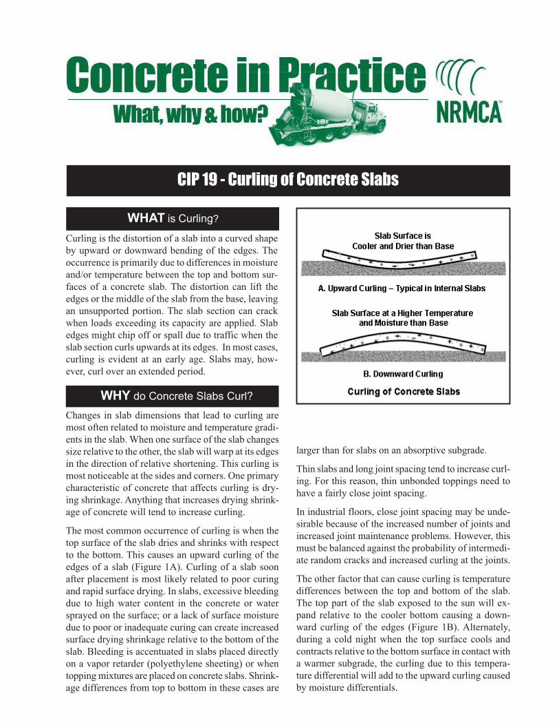
CIP 19 - Curling of Concrete Slabs
WHAT is Curling?
WHY do Concrete Slabs Curl?
Curling is the distortion of a slab into a curved shape
by upward or downward bending of the edges. The
occurrence is primarily due to differences in moisture
and/or temperature between the top and bottom sur-
faces of a concrete slab. The distortion can lift the
edges or the middle of the slab from the base, leaving
an unsupported portion. The slab section can crack
when loads exceeding its capacity are applied. Slab
edges might chip off or spall due to traffic when the
slab section curls upwards at its edges. In most cases,
curling is evident at an early age. Slabs may, how-
ever, curl over an extended period.
Changes in slab dimensions that lead to curling are
most often related to moisture and temperature gradi-
ents in the slab. When one surface of the slab changes
size relative to the other, the slab will warp at its edges
in the direction of relative shortening. This curling is
most noticeable at the sides and corners. One primary
characteristic of concrete that affects curling is dry-
ing shrinkage. Anything that increases drying shrink-
age of concrete will tend to increase curling.
The most common occurrence of curling is when the
top surface of the slab dries and shrinks with respect
to the bottom. This causes an upward curling of the
edges of a slab (Figure 1A). Curling of a slab soon
after placement is most likely related to poor curing
and rapid surface drying. In slabs, excessive bleeding
due to high water content in the concrete or water
sprayed on the surface; or a lack of surface moisture
due to poor or inadequate curing can create increased
surface drying shrinkage relative to the bottom of the
slab. Bleeding is accentuated in slabs placed directly
on a vapor retarder (polyethylene sheeting) or when
topping mixtures are placed on concrete slabs. Shrink-
age differences from top to bottom in these cases are
larger than for slabs on an absorptive subgrade.
Thin slabs and long joint spacing tend to increase curl-
ing. For this reason, thin unbonded toppings need to
have a fairly close joint spacing.
In industrial floors, close joint spacing may be unde-
sirable because of the increased number of joints and
increased joint maintenance problems. However, this
must be balanced against the probability of intermedi-
ate random cracks and increased curling at the joints.
The other factor that can cause curling is temperature
differences between the top and bottom of the slab.
The top part of the slab exposed to the sun will ex-
pand relative to the cooler bottom causing a down-
ward curling of the edges (Figure 1B). Alternately,
during a cold night when the top surface cools and
contracts relative to the bottom surface in contact with
a warmer subgrade, the curling due to this tempera-
ture differential will add to the upward curling caused
by moisture differentials.
1990, 2002, 2004
References
1. Guide for Concrete Floor and Slab Construction, ACI 302.1R
American Concrete Institute, Farmington Hills, MI
www.concrete.org
2. Slabs on Grade, ACI Concrete Craftsman Series, CCS-1
American Concrete Institute, Farmington Hills, MI.
3. Shrinkage and Curling of Slabs on Grade, Series in three
parts, R. F. Ytterberg, ACI Concrete International, April, May
and June 1987, American Concrete Institute.
4. Concrete Slab Surface Defects: Causes, Prevention, Repair,
IS177, Portland Cement Association, Skokie, IL,
www.cement.org
5. Pavement Design, Transportation Research Record 1207,
National Research Council, Washington, D.C., 1988, p. 44.
6. Controlling Curling and Cracking in Floors to Receive Cov-
erings, J. Holland and W. Walker, Concrete Construction, July
1998, www.worldofconcrete.com.
7. Where to Place the Vapor Retarder, B. Suprenant and W.
Malisch, Concrete Construction, May 1998.
8. Repairing Curled Slabs, B. Suprenant, Concrete Construc-
tion, May 1999.
9. Residential Concrete, National Association of Home Build-
ers, Washington, DC, www.nahb.com.
HOW to Minimize Slab Curling?
The primary factors controlling dimensional changes
of concrete that lead to curling are drying shrinkage,
construction practices, moist or wet subgrades, and
day-night temperature cycles. The following practices
will help to minimize the potential for curling:
1. Use the lowest practical water content in the con-
crete.
2. Use the largest practical maximum size aggregate
and/or the highest practical coarse aggregate con-
tent to minimize drying shrinkage.
3. Take precautions to avoid excessive bleeding. In
dry conditions place concrete on a damp, but ab-
sorptive, subgrade so that all the bleed water is
not forced to the top of the slab. This may not be
appropiate for interior slabs on which a moisture
sensitive floor covering would be placed.
4. Avoid using polyethylene vapor retarders unless
covered with at least four inches (100 mm) of a
trimable, compactible granular fill (not sand). If a
moisture-sensitive floor covering will be placed
on interior slabs, the concrete will generally be
placed directly on a vapor retarder (see CIP29)
and other procedures may be necessary.
5. Avoid a higher than necessary cement content. Use
of pozzolan or slag is preferable to very high ce-
ment content.
6. Cure the concrete thoroughly, including joints and
edges. If membrane-curing compounds are used,
apply at twice the recommended rate in two appli-
cations at right angles to each other.
7. When minimizing curling is critical, use a joint
spacing not exceeding 24 times the thickness of
the slab.
8. For thin toppings, clean the base slab to ensure
bond and consider use of studs and wire around
the edges and particularly in the slab corners.
9. Use a thicker slab, or increase the thickness of the
slab at edges.
10.The use of properly designed and placed slab re-
inforcement may help reduce or eliminate curl-
ing. Load transfer devices that minimize vertical
movement should be used across construction
joints.
11.Certain types of breathable sealers or coatings on
slabs can work to minimize moisture differentials
and reduce curling.
When curling in a concrete slab application cannot be
tolerated alternate options include the use of shrink-
age reducing admixtures, shrinkage-compensating con-
crete, post tensioned slab construction or vacuum de-
watering. These options should be decided before the
construction and could increase the initial cost of the
project.
Some methods of remedying slab curling include
ponding the slab to reduce curl followed by sawing
additional contraction joints, grinding slab joints where
curling has occurred to restore serviceability and in-
jecting a grout to fill voids under the slab to restore
support and prevent break-off of uplifted edges.

CIP 20 - Delamination of Troweled Concrete Surfaces
WHAT are Delaminations?
WHY does Delamination Occur?
In most delaminated concrete slab surfaces, the top 1/8 to ¼
inch (3 to 6 mm) is densified, primarily due to premature and
improper finishing, and separated from the base slab by a thin
layer of air or water. The delaminations on the surface of a
slab may range in size from several square inches to many
square feet. The concrete slab surface may exhibit cracking
and color differences because of rapid drying of the thin sur-
face during curing. Traffic or freezing may break away the
surface in large sheets. Delaminations are similar to blisters,
but much larger (see CIP 13).
Delaminations form during final troweling. They are more fre-
quent in early spring and late fall when concrete is placed on a
cool subgrade with rising daytime temperatures, but they can
occur at anytime depending on the concrete characteristics and
the finishing practices used.
Corrosion of reinforcing steel near the concrete surface or poor
bond between two-course placements may also cause delami-
nations (or spalling). The resulting delaminations are gener-
ally thicker than those caused by improper finishing.
Delaminations are difficult to detect during finishing but be-
come evident after the concrete surface has set and dried.
Delaminations can be detected by a hollow sound when tapped
with a hammer or with a heavy chain drag. A procedure is
described in ASTM D 4580, Standard Practice for Measur-
ing Delaminations in Concrete Bridge Decks by Sounding.
More sophisticated techniques include acoustic impact echo
and ground-penetrating radar.
Bleeding is the upward flow of mixing water in plastic con-
crete as a result of the settlement of the solids. Delamination
occurs when the fresh concrete surface is sealed or densified
by troweling while the underlying concrete is still plastic and
continues to bleed and/or to release air. Delaminations form
fairly late in the finishing process after floating and after the
first troweling pass. They can, however, form during the float-
ing operation if the surface is overworked and densified. The
chances for delaminations are greatly increased when condi-
tions promote rapid drying of the surface (wind, sun, or low
humidity). Drying and higher temperature at the slab surface
makes it appear ready to trowel while the underlying concrete
is plastic and can still bleed or release air. Vapor retarders placed
directly under slabs force bleed water to rise and compound the
problem.
Factors that delay initial set of the concrete and reduce the rate
of bleeding will increase the chances for delaminations. En-
trained air in concrete reduces the rate of bleeding and pro-
motes early finishing that will produce a dense impermeable
surface layer. A cool subgrade delays set in the bottom relative
to the top layer.
Delamination is more likely to form if:
1. The underlying concrete sets slowly because of a cool
subgrade.
2. The setting of the concrete is retarded due to concrete tem-
perature or mixture ingredients.
3. The concrete has entrained air or the air content is higher
than desirable for the application.
4. The concrete mixture is sticky from higher cementitious
material or sand-fines content.
5. Environmental conditions during placement are conducive
Delaminated Concrete
DENSE TROWELED SURFACE
DELAMINATION ZONE
AIR AND BLEED WATER
1992, 2002, 2004
HOW to Prevent Delamination?
to rapid drying causing the surface to “crust” and appear
ready to finish.
6. Concrete is excessively consolidated, such as the use of a
jitterbug or vibrating screed that brings too much mortar
to the surface.
7. A dry shake is used, particularly with air-entrained con-
crete.
8. The slab is thick.
9. The slab is placed directly on a vapor retarder.
Corrosion-related delaminations are formed when the upper
layer of reinforcing steel rusts thereby breaking the bond be-
tween the steel and the surrounding concrete. Corrosion of steel
occurs with reduced concrete cover and when the concrete is
relatively more permeable causing chlorides to penetrate to the
layer of the steel (See CIP 25).
Follow These Rules to Avoid Delamination
1. Do not seal surface early—before air or bleed water from below have escaped.
2. Avoid dry shakes on air-entrained concrete.
3. Use heated or accelerated concrete to promote even setting throughout slab depth.
4. Avoid placing concrete directly on vapor retarders, if the application allows.
5. Do not use air-entrained concrete for interior slabs that will receive a trowel finish.
6. Avoid placing concrete on substrate with a temperature of less than 40° F (4° C).
1. Guide for Concrete Floor and Slab Construction, ACI
302.1R American Concrete Institute, Farmington Hills,
MI www.concrete.org
2. Slabs on Grade, ACI Concrete Craftsman Series, Ameri-
can Concrete Institute, Farmington Hills, MI.
3. Concrete Slab Surface Defects: Causes, Prevention,
Repair, IS177, Portland Cement Association, Skokie,
IL, www.cement.org
4. Diagnosing Slab Delaminations – Series in three parts,
B. Suprenant, Concrete Construction, January, Febru-
ary and March 1998, www.worldofconcrete.com.
5. Using the Right Finishing Tool at the Right Time, R.H.
Spannenberg, Concrete Construction, May 1996.
6. Concrete in Practice Series, NRMCA, Silver Spring,
Maryland, www.nrmca.org.
7. Residential Concrete, National Association of Home
Builders, Washington, DC, www.nahb.com.
8. ASTM D 4580, Annual Book of ASTM Standards, Vol
04.03, ASTM International, West Conshohocken, PA,
www.astm.org.
References
Accelerators or heated concrete often prevent delamination in
cool weather.
Be wary of a concrete surface that appears to be ready to trowel
before it would normally be expected. Emphasis in finishing
should be on screeding, straight-edging, and floating the con-
crete as rapidly as possible—without working up an excessive
layer of mortar and without sealing the surface layer. In initial
floating, the float blades should be flat to avoid densifying the
surface too early.
Final finishing operations to produce a smooth surface should
be delayed as long as possible, and the surface covered with
polyethylene or otherwise protected from evaporation.
Delamination may be difficult to detect during finishing op-
erations. If delamination is observed, tear the surface with a
wood float and delay finishing as long as possible. Any steps
that can be taken to slow evaporation should help.
If a vapor retarder is required, place at least four inches (100
mm) of a trimable, compactible granular fill (not sand). Do not
place concrete directly on a vapor retarder. If a moisture-sensi-
tive floor covering will be placed on interior slabs, concrete
will generally be placed directly on a vapor retarder (see CIP
29), and other procedures may be necessary.
Do not use air-entrained concrete for interior floor slabs that
have a hard troweled surface and that will not be subject to
freeze-thaw cycles or deicing salt application. If entrained air
is necessary to protect interior slabs from freezing and thawing
cycles during construction avoid using air contents over 3%.
Delaminated surfaces can be repaired by patching after the sur-
face layer is removed and the underlaying concrete is properly
cleaned. Extensive delamination may need to be repaired by
grinding and overlaying a new surface. Delaminated surfaces
due to steel corrosion will additionally require sandblasting to
remove rust from the steel.
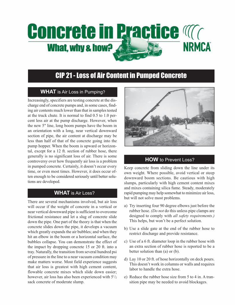
CIP 21 - Loss of Air Content in Pumped Concrete
WHAT is Air Loss in Pumping?
WHAT is Air Loss?
Increasingly, specifiers are testing concrete at the dis-
charge end of concrete pumps and, in some cases, find-
ing air contents much lower than that in samples tested
at the truck chute. It is normal to find 0.5 to 1.0 per-
cent less air at the pump discharge. However, when
the new 5" line, long boom pumps have the boom in
an orientation with a long, near vertical downward
section of pipe, the air content at discharge may be
less than half of that of the concrete going into the
pump hopper. When the boom is upward or horizon-
tal, except for a 12 ft. section of rubber hose, there
generally is no significant loss of air. There is some
controversy over how frequently air loss is a problem
in pumped concrete. Certainly, it doesn’t occur every
time, or even most times. However, it does occur of-
ten enough to be considered seriously until better solu-
tions are developed.
There are several mechanisms involved, but air loss
will occur if the weight of concrete in a vertical or
near vertical downward pipe is sufficient to overcome
frictional resistance and let a slug of concrete slide
down the pipe. One part of the theory is that when the
concrete slides down the pipe, it develops a vacuum
which greatly expands the air bubbles; and when they
hit an elbow in the boom or a horizontal surface, the
bubbles collapse. You can demonstrate the effect of
the impact by dropping concrete 15 or 20 ft. into a
tray. Naturally, the transition from several hundred psi
of pressure in the line to a near vacuum condition may
make matters worse. Most field experience suggests
that air loss is greatest with high cement content,
flowable concrete mixes which slide down easier;
however, air loss has also been experienced with 51/2
sack concrete of moderate slump.
Keep concrete from sliding down the line under its
own weight. Where possible, avoid vertical or steep
downward boom sections. Be cautious with high
slumps, particularly with high cement content mixes
and mixes containing silica fume. Steady, moderately
rapid pumping may help somewhat to minimize air loss,
but will not solve most problems.
a) Try inserting four 90 degree elbows just before the
rubber hose. (Do not do this unless pipe clamps are
designed to comply with all safety requirements.)
This helps, but won’t be a perfect solution.
b) Use a slide gate at the end of the rubber hose to
restrict discharge and provide resistance.
c) Use of a 6 ft. diameter loop in the rubber hose with
an extra section of rubber hose is reported to be a
better solution than (a) or (b).
d) Lay 10 or 20 ft. of hose horizontally on deck pours.
This doesn’t work in columns or walls and requires
labor to handle the extra hose.
e) Reduce the rubber hose size from 5 to 4 in. A tran-
sition pipe may be needed to avoid blockages.
HOW to Prevent Loss?

1992
PRECAUTIONS
a) Before the pour, plan alternative pump locations
and decide what will be done if air loss occurs. Be
prepared to test for air content frequently.
b) Sampling from the end of a pump line can be very
difficult. Wear proper personal protective equip-
ment. Never sample the initial concrete through the
pump line.
c) Sample the first load on the job after pumping
3 or 4 cu. yds. Temper it to the maximum
permissible slump. Swing the boom over near the
pump to get the maximum length of vertical down-
ward pipe and drop the sample in a wheel barrow.
If air is lost, take precautions and sample at the point
of placement.
d) If air loss occurs, do not try to solve the problem by
increasing the air content delivered to the pump
beyond the upper specification limit. High air con-
tent concrete with low strength could, or almost
surely will, be placed in the structure if boom angles
are reduced or somewhat lower slump concrete is
pumped.
References
1 . Gaynor, R.D., “Summer Problem Solving,” Concrete
Products, June, 1991, p. 11.
2. Gaynor, R.D., “Current Research at NRMCA,” Concrete Prod-
ucts, April, 1992, pp. 6-7.
3. Hoppe, Julian J., “Air Loss in Free-Falling Concrete,”
Queries on Concrete, Concrete International, June 1992,
p. 79.
4. Gorsha, Russel P., “Air Loss in Free-Falling Concrete,
Queries on Concrete, Concrete International, August 1992, p.
71.
5. “Effects of Pumping Air Entrained Concrete,” Washington Ag-
gregates and Concrete Association, March 20, 1991, 12 pp.
6. Dyer, R.M., “An Investigation of Concrete Pumping Pressure
and the Effects on the Air Void System of Concrete,” Master’s
Thesis, Department of Civil Engineering, University of Wash-
ington, Seattle, Washington, 1991.
7. Personal correspondence with authors and photographs, July
13, 1992 (copies available on request).
8. Yingling, James; G.M. Mullings; and R.D. Gaynor, “Loss of
Air Content in Pumped Concrete,” Concrete International,
Volume 14, Number 10, October 1992, pp. 57-61.

CIP 22 - Grout
WHAT is Grout?
WHY does Delamination Occur?
ACI1 defines grout as “a mixture of cementitious
material and water, with or without aggregate, pro-
portioned to produce a pourable consistency without
segregation of the constituents.”
The terms grout and mortar are frequently used inter-
changeably but there are clear distinctions. Grout need
not contain aggregate whereas mortar contains fine
aggregate. Grout is supplied in a pourable consistency
whereas mortar is not. Grout fills space whereas mortar
bonds elements together, as in masonry construction.
Grout is often identified by its application. Some
examples are: bonded prestressed tendon grout, au-
ger cast pile grout, masonry grout, and pre-placed ag-
gregate grout. Controlled low strength material
(flowable fill) is a type of grout.
Flow Cone
Flow Table
Grout is used to fill space or cavities and provide con-
tinuity between building elements. In some applica-
tions, grout will act in a structural capacity. In projects
where small quantities of grout are required, it is pro-
portioned and mixed on site. The ready mixed con-
crete producer is generally called upon when large
quantities are needed.
HOW to Specify Grout?
ASTM C 476 for masonry grout dictates proportions
by loose volumes and is convenient for small quanti-
ties of grout mixed on site. These grout mixtures have
high cement contents and tend to produce much higher
strengths4 than specified in ACI 5305 or Model Codes.
When grout is ordered from a ready mixed concrete
producer, the specifications should be based on con-
sistency and compressive strength. Converting loose
volume proportions into batch weights per cubic yard is
subject to errors and can lead to controversies on the job.
Specifications should address the addition of any
required admixtures for grout. Conditions of delivery,
such as temperature, time limits, and policies on
job site addition of water, should be specified. Testing
frequency and methods of acceptance must be covered
in specifications.
HOW to Test Grout?
The consistency of grout affects its strength and other
properties. It is critical that grout consistency permit
the complete filling of void space without segregation
of ingredients.
Consistency of masonry grout may be measured with a
slump cone (ASTM C 143), and slumps of 8-11 in. are
suggested. This is particularly applicable for grouts
containing 1/2 in. or smaller coarse aggregate.
For grouts without aggregate, or only fine aggregate
passing a No. 8 sieve, consistency is best determined
with a flow cone (ASTM C 939). For flow values ex-
ceeding 35 seconds, use the flow table in ASTM C 109,
so modified to use 5 drops in 3 seconds.
Masonry grout (“blockfill”) for strength tests specimens

1993
1. “Cement and Concrete Terminology,” ACI Committee 116R,
ACI Manual of Concrete Practice, Part 1.
2. Cementitious Grouts and Grouting, S. H. Kosmatka, Port-
land Cement Association, 1990.
3. ASTM C 476, “Standard Specification for Grout for Ma-
sonry,” Annual Book of ASTM Standards, Vol. 04.05.
4. Hedstrom, E. G., and Hogan, M. B., “The Properties of Ma-
sonry Grout in Concrete Masonry,” Masonry: Components
to Assemblages, ASTM STP 1063, ed. John H. Matthys, 1990,
pp. 47-62.
5. “Building Code Requirements for Masonry Structures
(ACI 530-88/ASCE 5-88) and Specifications for Masonry
Structures (ACI 530.1-88/ASCE 6-88),” ACI-ASCE
Standards, American Concrete Institute/American Society of
Civil Engineers, 1988.
6. ASTM C 143, “Test Method for Slump of Hydraulic Cement
Concrete,” Annual Book of ASTM Standards, Vol. 04.02.
7. ASTM C 939, “Test Method for Flow of Grout for Preplaced
Aggregate Concrete (Flow Cone Method),” Annual Book of
ASTM Standards, Vol. 04.02.
8. ASTM C 1019, “Standard Method of Sampling and Testing
Grout,” Annual Book of ASTM Standards, Vol. 04.05.
9. ASTM C 942, “Standard Test Method for Compressive
Strengths of Grouts for Preplaced-Aggregate Concrete
in the Laboratory,” Annual Book of ASTM Standards,
Vol. 04.02.
10. ASTM C 109, “Standard Test Method for Compressive
Strength of Hydraulic Cement Mortars,” Annual Book of
ASTM Standards, Vol. 04.01.
Referencesshould be cast in molds formed by masonry units hav-
ing the same absorption characteristics and moisture
content as the units used in construction (ASTM C
1019). Never use nonabsorbent cube or cylinder molds
for this purpose.
Strength of other types of grout is determined using 2
in. cubes per ASTM C 942. Method C 942 allows for
field preparation, recognizes fluid consistency, and also
affords a means for determining compressive strength
of grouts that contain expansive agents or grout
fluidifiers. This is extremely important since “expan-
sive” grouts can lose substantial compressive strengths
if cubes are not confined. However, cylindrical speci-
mens (6 x 12 in. or 4 x 8 in.), may give more reliable
results for grouts containing coarse aggregate.
Special application grouts often require modification
of standard test procedures. All such modifications
should be noted in the specifications and discussed
prior to the start of the job.
Comparison of typical slumps

CIP 23 - Discoloration
WHAT is Discoloration?
WHY does Discoloration Occur?
Surface discoloration is the non-uniformity of color
or hue on the surface of a single concrete placement.
It may take the form of dark blotches or mottled dis-
coloration on flatwork surface, gross color changes
in large areas of concrete caused by a change in the
concrete mix, or light patches of discoloration caused
by efflorescence. In this context, it is not intended to
include stains caused by foreign material spilled on a
concrete surface.6
Discoloration due to changes in cement or fine
aggregate sources in subsequent batches in a place-
ment sequence could occur, but is generally rare and
insignificant. Cement that has hydrated to a greater
extent will generally be lighter in color. Inconsistent
use of admixtures, insufficient mixing time, and
improper timing of finishing operations can cause this
effect. A yellowish to greenish hue may appear on
concrete containing ground slag as a cementitious
material. This will disappear with time. Concrete con-
taining ground slag does, however, have a generally
lighter color. The discoloration of concrete cast in
forms or in slabs on grade is usually the result of a
change in either the concrete composition or a con-
crete construction practice. In most studies, no single
factor seemed to cause discoloration.
Factors found to influence discoloration are: the use
of calcium chloride, variation in cement alkali con-
tent, delayed hydration of the cement paste, admix-
tures, hard-troweled surfaces, inadequate or inappro-
priate curing, concreting practices and finishing pro-
cedures that cause surface variation of the water-ce-
ment ratio, and changes in the concrete mix.1,2,3,7
HOW to Prevent Discoloration?
1. Minimizing or eliminating the use of high-alkali
content cements will reduce the occurrence of dis-
coloration.
2. Calcium chloride in concrete is a primary cause of
concrete discoloration. The chances for dis-
coloration are much less if calcium chloride or
chloride- bearing chemical admixtures are
not used.
3. The type, kind, and condition of formwork can in-
fluence surface color. Forms with different rates
of absorption will cause surfaces with different
shades of color. A change in the type or brand of a
form release agent can also change concrete color.
4. Eliminate trowel burning of the concrete. The most
common consequence is that metal fragments from
the trowel are embedded in the surface of the con-
crete. Also, concrete which has been hard-trow-
eled may have dark discoloration as a result of den-

1993
Certain treatments have been found to be successful
in removing or decreasing the surface discoloration of
concrete flatwork. Discoloration caused by calcium
chloride admixtures and some finishing and curing
methods can be reduced by repeated washing with hot
water and a scrub brush. The slab should be alternately
flushed and brushed, and then dried overnight until
the discoloration disappears.
If a discoloration persists, a dilute solution (1% con-
centration) of hydrochloric (muriatic) acid or dilute
solutions (3% concentration) of weaker acids like
acetic or phosphoric acid may be tried. Prior to using
acids, dampen the surface to prevent it from penetrat-
ing into the concrete and flush with clean water within
15 minutes of application.
The use of a 20% to 30% water solution of di-
ammonium citrate (2 lbs. in 1 gallon of water) has been
found to be a very effective treatment by the PCA for
more severe cases of discoloration.4,5,6 Apply the so-
lution to a dried surface for 15 minutes. A whitish gel
HOW to Remove Discoloration?
References
sifying the surface, which reduces the water-cement
ratio. The resulting low water-cement ratio affects
the hydration of the cement ferrites which contrib-
utes to a darker color. Concrete surfaces that are
troweled too early will increase the water-cement
ratio at the surface and lighten the color.
5. Concrete which is not properly or uniformly cured
may develop discoloration. Uneven curing will af-
fect the degree of hydration of the cement. Curing
with polyethylene may also cause discoloration.
When the plastic sheeting is in direct contact with
the concrete, it will cause streaks. Using an even
application of a quality spray or curing compound
may be the better alternative.
6. The discoloration of a slab may be minimized or
prevented by moistening absorptive subgrades, fol-
lowing proper curing procedures, and adding proper
protection of the concrete from drying by the wind
and sun.
that forms should be diluted with water and brushed.
Subsequently, the gel should be completely washed
off with water. More than one treatment may be re-
quired.
Some types of discoloration, such as trowel burning,
may not respond to any treatment. It may be necessary
to paint or use another type of coating to eliminate the
discoloration. Some types of discoloration may, how-
ever, fade with wear and age.
PRECAUTIONS?
Chemical methods to remove discoloration may sig-
nificantly alter the color of concrete surfaces. Inap-
propriate or improper use of chemicals to remove dis-
coloration may aggravate the situation. A trial treat-
ment on an inconspicuous area is recommended. Ac-
ids should be thoroughly flushed from a concrete sur-
face.
CAUTIONS
The user of chemicals should refer to a Material
Safety Data Sheet (MSDS) or manufacturer guide-
lines to be aware of the toxicity, flammability,
and/or health hazards associated with the use of
the material. The appropriate safety procedures,
such as the use of gloves, goggles, respirators, and
waterproof clothing, are recommended.
1. “Surfaces Discoloration of Flatwork,” Greening, N. R. and
Landgren, R., Portland Cement Association Research Department
Bulletin RX 203, 1966.
2. “Discoloration of Concrete, Causes and Remedies,” Kosmatka,
S. H., Concrete Products, April 1987.
3. “Discoloration of Concrete Flatwork,” Neal, R. E., Lehigh Port-
land Cement Company, 1977.
4. “Removing Stains and Cleaning Concrete Surfaces,” PCA, 1988.
5. “Discoloration: Myths, Causes and Cures,” Rech, D. P., Owl Rock
Products, 1989.
6. “Removing Stains from Mortar and Concrete,” Corps of En-
gineers Miscellaneous Paper C-6808.
7. “Discolored Concrete Surfaces,” Goeb, Eugene O., Concrete Prod-
ucts, Vol. 96, No. 2, February, 1993.

CIP 24 - Synthetic Fibers for Concrete
WHAT are Synthetic Fibers?
Synthetic fibers specifically engineered for concrete
are manufactured from man-made materials that can
withstand the long-term alkaline environment of
concrete. Synthetic fibers are added to concrete be-
fore or during the mixing operation. The use of syn-
thetic fibers at typical addition rates does not require
any mix design changes.
WHY Use Synthetic Fibers ?
HOW do Synthetic Fibers Work in
Early Age Concrete?
HOW do Synthetic Fibers Work in
Hardened Concrete?
Synthetic fibers benefit the concrete in both the plas-
tic and hardened state. Some of the benefits include:
• reduced plastic settlement cracks
• reduced plastic shrinkage cracks
• lowered permeability
• increased impact and abrasion resistance
• providing shatter resistance
Some synthetic fibers may be used as secondary rein-
forcement. (Hardened Concrete Performance Docu-
mentation Required.)
Early age volume changes in concrete cause weak-
ened planes and cracks to form because a stress exists
which exceeds the strength of the concrete at a spe-
cific time. The growth of these micro shrinkage cracks
is inhibited by mechanical blocking action of the
synthetic fibers. The internal support system of the
synthetic fibers inhibits the formation of plastic settle-
ment cracks. The uniform distribution of fibers
throughout the concrete discourages the development
of large capillaries caused by bleed water migration
to the surface. Synthetic fibers lower permeability
through the combination of plastic crack reduction and
The early age concrete benefits of using synthetic
fibers continue to contribute to the hardened concrete.
Hardened concrete attributes provided by synthetic
fibers are lowered permeability and the resistance to
shattering, abrasion, and impact forces.
The ability to resist shattering forces is greatly en-
hanced with the introduction of synthetic fibers to the
concrete. When plain concrete is compressed, it will
shatter and fail at first crack. Synthetic fibers manu-
factured specifically for concrete prevent the effect
of shattering forces by tightly holding the concrete
together.
Abrasion resistance is provided when synthetic fibers
are used because the water-cement ratio at the
surface is not lowered by variable bleed water. The
water-cement ratio is more constant at the concrete
surface. This improvement is assisted by the internal
settlement support value of the synthetic fibers
contributing to uniform bleeding.
Synthetic fibers reduce the amount of plastic crack-
ing of the concrete. This improves the impact resis-
tance of concrete. The relatively low modulus of the
synthetic fibers provides shock absorption character-
istics.
Synthetic fibers help the concrete develop its
optimum long-term integrity by the reduction of
plastic settlement and shrinkage crack formation,
lowered permeability, and increased resistance to
abrading, shattering, and impact forces. Synthetic
fibers are compatible with all admixtures, silica fumes,
and cement chemistries.
reduced bleeding characteristics.

1994
APPLICATION GUIDELINES
Do Use Synthetic Fibers For:
• The reduction of concrete cracking as a result of plastic shrinkage.
• An alternate system of nonstructural secondary and/or temperature reinforcement.
• Greater impact, abrasion, and shatter resistance in concrete.
• Internal support and cohesiveness; the concrete for steep inclines, shotcrete, and slipformed placements.
• The reduction of concrete cracking as a result of plastic settlement.
• To help lower the permeability of concrete.
• Placements where nonmetallic materials are required.
• Areas requiring materials that are both alkali proof and chemical resistant.
Do Not Use Synthetic Fibers For:
• The control of cracking as a result of external forces.
• Higher structural strength development.
• Replacement of any moment-resisting or structural steel reinforcement.
• Decreasing the thickness of slabs on grade.
• The elimination or reduction of curling and/or creep.
• Increasing of ACI or PCA control joint guidelines.
• The justification for a reduction in the size of the support columns.
• The thinning out of bonded or unbonded overlay sections.
HOW are Synthetic Fibers Used as Sec-
ondary Reinforcement?
Synthetic fibers which meet certain hardened concrete
criteria can be used as nonstructural temperature or
secondary reinforcement. These fibers should have
documentation confirming their ability to hold con-
crete together after cracking.
The uniform distribution of synthetic fibers through-
out the concrete ensures the critical positioning of sec-
ondary reinforcement.
References
1. ASTM C 1116 Standard Specification Fiber Reinforced
Concrete and Shotcrete.
2. ASTM C 1018 Standard Test Method for Flexural Toughness
and First-Crack Strength of Fiber Reinforced Concrete
(Using Beam with Third-Point Loading).
3. ASTM C 78 Test Method for Flexural Strength of Concrete
(Using Simple Beam with Third-Point Loading).
4. Non-structural Cracks in Concrete, Concrete Society Techni-
cal Report No. 22.
5. ICBO Evaluation Service, Inc., Acceptance Criteria for
Concrete with Synthetic Fibers, January 1993.

CIP 25 - Corrosion of Steel in Concrete
WHY is Corrosion of Steel a Concern?
WHY Does Steel in Concrete Corrode?
HOW to Prevent Corrosion?
WHAT is Corrosion of Steel?
ASTM terminology (G 15) defines corrosion as “the
chemical or electrochemical reaction between a mate-
rial, usually a metal, and its environment that produces a
deterioration of the material and its properties.” For steel
embedded in concrete, corrosion results in the forma-
tion of rust which has two to four times the volume of
the original steel and none of its good mechanical prop-
erties. Corrosion also produces pits or holes in the sur-
face of reinforcing steel, reducing strength capacity as a
result of the reduced cross-sectional area.
Reinforced concrete uses steel to provide the tensile
properties that are needed in structural concrete. It pre-
vents the failure of concrete structures which are sub-
jected to tensile and flexural stresses due to traffic, winds,
dead loads, and thermal cycling. However, when rein-
forcement corrodes, the formation of rust leads to a loss
of bond between the steel and the concrete and subse-
quent delamination and spalling. If left unchecked, the
integrity of the structure can be affected. Reduction in
the cross-sectional area of steel reduces its strength ca-
pacity. This is especially detrimental to the performance
of tensioned strands in prestressed concrete.
Steel in concrete is usually in a noncorroding, passive
condition. However, steel-reinforced concrete is often
used in severe environments where sea water or deicing
salts are present. When chloride moves into the concrete,
it disrupts the passive layer protecting the steel, causing
it to rust and pit.
Carbonation of concrete is another cause of steel corro-
sion. When concrete carbonates to the level of the steel
rebar, the normally alkaline environment, which protects
steel from corrosion, is replaced by a more neutral envi-
ronment. Under these conditions the steel is not passive
and rapid corrosion begins. The rate of corrosion due to
carbonated concrete cover is slower than chloride-in-
duced corrosion.
Occasionally, a lack of oxygen surrounding the steel rebar
will cause the metal to dissolve, leaving a low pH liquid.
Quality Concrete—Concrete Practices
The first defense against corrosion of steel in concrete is
quality concrete and sufficient concrete cover over the
reinforcing bars. Quality concrete has a water-to-
cementitious material ratio (w/c) that is low enough to
slow down the penetration of chloride salts and the de-
velopment of carbonation. The w/c ratio should be less
than 0.50 to slow the rate of carbonation and less than
0.40 to minimize chloride penetration. Concretes with
low w/c ratios can be produced by (1) increasing the
cement content; (2) reducing the water content by using
water reducers and superplasticizers; or (3) by using
larger amounts of fly ash, slag, or other cementitious ma-
terials. Additionally, the use of concrete ingredients con-
taining chlorides should be limited. The ACI 318 Build-
ing Code provides limits on the maximum amount of
soluble chlorides in the concrete mix.
Another ingredient for good quality concrete is air en-
trainment. It is necessary to protect the concrete from

1995
HOW to Limit Corrosion
1. Use good quality concrete-air entrained with a w/c of 0.40, or less.
2. Use a minimum concrete cover of 1.5 inches and at least 0.75 inch larger than the nominal maximum sizeof the coarse aggregate.
3. Increase the minimum cover to 2 inches for deicing salt exposure and to 2.5 inches for marine exposure.
4. Ensure that the concrete is adequately cured.
5. Use fly ash, blast-furnace slag, or silica fume and/or a proven corrosion inhibitor.
freezing and thawing damage. Air entrainment also re-
duces bleeding and the corresponding increased perme-
ability due to the bleed channels. Spalling and scaling
can accelerate corrosion damage of the embedded rein-
forcing bars. Proper scheduling of finishing operations
is needed to ensure that the concrete does not scale, spall,
or crack excessively.
The correct amount of steel will help keep cracks tight.
ACI 224 helps the design engineer to minimize the for-
mation of cracks that could be detrimental to embedded
steel. In general, the maximum allowable crack widths
are 0.007 inch in deicing salt environments and 0.006
inch in marine environments.
Adequate cover over reinforcing steel is also an impor-
tant factor. Chloride penetration and carbonation will
occur in the outer surface of even low permeability con-
cretes. Increasing the cover will delay the onset of corro-
sion. For example, the time for chloride ions to reach a
steel rebar at 2 inches from the surface is four times that
with a 1 inch cover. ACI 318 recommends a minimum of
1.5 inches of cover for most structures, and increases it
to 2 inches of cover for protection from deicing salts.
ACI 357 recommends 2.5 inches of minimum cover in
marine environments. Larger aggregates require more
cover. For aggregates greater than 3/4 inch, a rule of thumb
is to add to the nominal maximum aggregate size 3/4 inch
of cover for deicing salt exposure, or 1-3/4 inch of cover
for marine exposure. For example, concrete with 1 inch
aggregate in a marine exposure should have a 2-3/4 inch
minimum cover.
The concrete must be adequately consolidated and cured.
Moist curing for a minimum of seven days at 70°F is
needed for concrete with a 0.40 w/c ratio, whereas six
months is needed for a 0.60 w/c ratio to obtain equiva-
lent performance. Numerous studies show that concrete
porosity is reduced significantly with increased curing
times and, correspondingly, corrosion resistance is im-
proved.
References
Modified Concretes and Corrosion Protection Systems
Increased corrosion resistance can also come about by
the use of concrete additives. Silica fume, fly ash, and
blast-furnace slag reduce the permeability of the con-
crete to the penetration of chloride ions. Corrosion in-
hibitors, such as calcium nitrite, act to prevent corrosion
in the presence of chloride ions. In all cases, they are
added to quality concrete at w/c less than or equal to
0.45.
Water repellents may reduce the ingress of moisture and
chlorides to a limited extent. However, ACI 222 indi-
cates that these are not effective in providing long-term
protection. Since good quality concrete already has a low
permeability, the additional benefits of water repellents
are not as significant.
Other protection techniques include protective mem-
branes, cathodic protection, epoxy-coated reinforcing
bars, and concrete sealers (if reapplied every four to five
years).
1. “Building Code Requirements for Reinforced Concrete,” ACI 318,
American Concrete Institute, Farmington Hills, MI.
2. “Corrosion of Metals in Concrete,” American Concrete Institute,
Farmington Hills, MI.
3. “Control of Cracking in Concrete Structures,” ACI 224R, American
Concrete Institute, Farmington Hills, MI.
4. Design and Construction of Fixed Offshore Concrete Struc-
tures,” ACI 357R, American Concrete Institute, Farmington Hills, MI.
5. Perenchio, W.F., “Corrosion of Reinforcing Steel,” ASTM STP 169C,
1994, pp. 164-172.
6. Whiting, D., ed., Paul Klieger Symposium on Performance of Con-
crete, ACI SP-122, 1990, 499 pp.
7. Berke, N.S., “Corrosion Inhibitors in Concrete,” Concrete Interna-
tional, Vol. 13, No. 7, 1991, pp. 24-27.
8. Berke, N.S., Pfeifer, D.W., and Weil, T.G., “Protection Against Chlo-
ride Induced Corrosion,” Concrete International, Vol. 10, No. 12,
1988, pp. 44-55.

CIP 26 - Jobsite Addition of Water
WHY is Water Added at the Jobsite?
WHAT is Jobsite Addition of Water?
HOW to Add Water at the Jobsite?
Figure 1 Example of effect of water addition on slumpand strength of concrete
Jobsite addition of water is the addition of water to
ready mixed concrete in a truck mixer after arrival at
the location of the concrete placement. Such temper-
ing of concrete may be done with a portion of the de-
sign mixing water which was held back during the
initial mixing, or with water in excess of the design
mixing water, at the request of the purchaser.
When concrete arrives at the jobsite with a slump that
is lower than that allowed by design or specification
and/or is of such consistency so as to adversely affect
the placeability of the concrete, water can be added to
the concrete to bring the slump up to an acceptable or
specified level. This can be done when the truck
arrives on the jobsite as long as the specified slump
and/or water-cement ratio is not exceeded. Such an
addition of water is in accordance with ASTM C 94,
Standard Specification for Ready Mixed Concrete.
The ready mixed concrete supplier designs the con-
crete mixture according to industry standards to pro-
vide the intended performance. Addition of water in
excess of the design mixing water will affect concrete
properties, such as reducing strength (Figure 1), and
increasing its susceptibility to cracking. If the purchaser
requests additional water, in excess of the design mix,
the purchaser assumes responsibility for the resulting
concrete quality. The alternative of using a water re-
ducing admixture or superplacticizer to increase con-
crete slump should be considered. Provided segrega-
tion is avoided, increasing the slump of concrete us-
ing admixtures usually will not significantly alter con-
crete properties.
a. The maximum allowable slump of the concrete
must be specified or determined from the specified
nominal slump plus tolerances.
b. Prior to discharging concrete on the job, the actual
slump of the concrete must be estimated or deter-
mined. If the slump is measured, it should be on a
sample from the first 1/4 cu. yd. (0.2 m3) of dis-
charged concrete and the result used as an indica-
tor of concrete consistency and not an acceptance
test. Tests for acceptance of concrete should be
made in accordance with ASTM C 172.
c. At the jobsite, water should be added to the entire
batch so that the volume of concrete being retem-
pered is known. A rule of thumb that works rea-
sonably well is—1 gallon, or roughly 10 lb., of
water per cubic yard for 1 inch increase in slump
(5 liters, or 5 kg, of water per cubic meter for 25
mm increase in slump).
d. All water added to the concrete on the jobsite must

1995
References
1. ASTM C 94, Standard Specification for Ready Mixed
Concrete, ASTM, West Conshohocken, PA.
2. NRMCA Publication 186, “Ready Mixed Concrete” Richard
D. Gaynor, Silver Spring, Maryland.
3. NRMCA QC2—Appendix on Agenda for a Pre-Placement
Conference, Silver Spring, Maryland.
4. NRMCA Publication 188, ‘Truck Mixer Driver’s Manual,’ Sil-
ver Spring, Maryland.
5. “Adding Water to the Mix: It’s Not all Bad,” Eugene O. Goeb,
Concrete Products, January 1994.
6. “Adjusting Slump in the Field,” Bruce A. Suprenant,
Concrete Construction, January 1994.
7. “Effect of Prolonged Mixing on the Compressive Strength
of Concrete with Fly Ash and/or Chemical Admixtures,”
Dan Ravina, submitted for publication, ACI Concrete
International, 1995.
ASTM C 94 Jobsite Water Addition
1. Establish the maximum allowable slump and water content permitted by the job specification.
2. Estimate or determine the concrete slump from the first portion of concrete discharged from the truck.
3. Add an amount of water such that the maximum slump or water-cement ratio according to the specification
is not exceeded.
4. Measure and record the amount of water added. Water in excess of that permitted above should be autho-
rized by a designated representative of the purchaser.
5. Mix the concrete for 30 revolutions of the mixer drum at mixing speed.
6. Do not add water if:
a. the maximum water-cement ratio is reached,
b. the maximum slump is obtained, or
c. more than 1/4 cu.yd. (0.2 m3 ) has been discharged from the mixer.
be measured and recorded.
e. ASTM C 94 requires an additional 30 revolutions
of the mixer drum at mixing speed after the addi-
tion of water. In fact, 10 revolutions will be suffi-
cient if the truck is able to mix at 20 revolutions
per minute (rpm) or faster.
f. The amount of water added should be controlled
so that the maximum slump and/or water-cement
ratio, as indicated in the specification, is not exceeded.
After more than a small portion of the concrete is
discharged, no water addition is permitted.
g. Upon obtaining the desired slump and/or maximum
water-cement ratio, no further addition of water on
the jobsite is permitted.
h. A pre-concreting conference should be held to
establish proper procedures to be followed, to
determine who is authorized to request a water
addition, and to define the method to be used for
documentation of water added at the jobsite.

CIP 27 - Cold Weather Concreting
WHY Consider Cold Weather?
WHAT is Cold Weather?
HOW to Place Concrete in Cold Weather?
Figure 1 Effect of Temperature on Set Time (1a)
Cold weather is defined as a period when the average daily
temperature falls below 40°F [4°C] for more than three suc-
cessive days. These conditions warrant special precautionswhen placing, finishing, curing and protecting concrete against
the effects of cold weather. Since weather conditions can
change rapidly in the winter months, good concrete practices
and proper planning are critical.
Successful cold-weather concreting requires an understand-
ing of the various factors that affect concrete properties.
In its plastic state, concrete will freeze if its temperature falls
below about 25°F [-4°C]. If plastic concrete freezes, its po-
tential strength can be reduced by more than 50% and its du-
rability will be adversely affected. Concrete should be pro-
tected from freezing until it attains a minimum compressive
strength of 500 psi [3.5 MPa], which is about two days after
placement for most concrete maintained at 50°F [10°C].
Low concrete temperature has a major effect on the rate of
cement hydration, which results in slower setting and rate
of strength gain. A good rule of thumb is that a drop in con-
crete temperature by 20°F [10°C] will approximately double
the setting time. The slower rate of setting and strength gainshould be accounted for when scheduling construction op-
erations, such as form removal.
Concrete in contact with water and exposed to cycles of
freezing and thawing, even if only during construction,
should be air-entrained. Newly placed concrete is saturated
with water and should be protected from cycles of freezing
and thawing until it has attained a compressive strength of
at least 3500 psi [24.0 MPa].
Cement hydration is a chemical reaction that generates heat.
Newly placed concrete should be adequately insulated to re-
tain this heat and thereby maintain favorable curing tempera-
tures. Large temperature differences between the surface andthe interior of the concrete mass should be prevented as crack-
ing may result when this difference exceeds about 35°F [20°C].
Insulation or protective measures should be gradually removed
to avoid thermal shock.
Recommended concrete temperatures at the time of
placement are shown below. The ready mixed concrete pro-
ducer can control concrete temperature by heating the mix-ing water and/or the aggregates and furnish concrete in ac-
cordance with the guidelines in ASTM C 94.
Section Size, minimum Concrete temperaturedimension, inch [mm] as placed
less than 12 [300] 55°F [13°C]
12 - 36 [300 - 900] 50°F [10°C]
36 - 72 [900 - 1800] 45°F [7°C]
Cold weather concrete temperature should not exceed these
recommended temperatures by more than 20°F [10°C]. Con-
crete at a higher temperature requires more mixing water, has a
higher rate of slump loss, and is more susceptible to cracking.
Placing concrete in cold weather provides the opportunity for
better quality, as cooler initial concrete temperature will
typically result in higher ultimate strength.
Slower setting time and strength gain of concrete during cold
weather typically delays finishing operations and form re-moval. Chemical admixtures and other modifications to the
concrete mixture can accelerate the rate of setting and strength
gain. Accelerating chemical admixtures, conforming to

1998
Cold Weather Concreting Guidelines1. Use air-entrained concrete when exposure to moisture and freezing and thawing conditions are expected.
2. Keep surfaces in contact with concrete free of ice and snow and at a temperature above freezing prior
to placement.
3. Place and maintain concrete at the recommended temperature.
4. Place concrete at the lowest practical slump.
5. Protect plastic concrete from freezing or drying.
6. Protect concrete from early-age freezing and thawing cycles until it has attained adequate strength.
7. Limit rapid temperature changes when protective measures are removed.
References
1. Cold Weather Concreting, ACI 306R, American Concrete
Institute, Farmington Hills, MI.
2. Design and Control of Concrete Mixtures, Portland Cement
Association, Skokie, IL.
3. ASTM C94 Standard Specification for Ready Mixed Concrete,
ASTM, West Conshohocken, PA.
4. ASTM C 31 Making and Curing Concrete Test Specimens in
the Field, ASTM, West Conshohocken, PA.
5. Cold Weather Ready Mixed Concrete, NRMCA Pub 130,
NRMCA, Silver Spring, MD.
6. Cold-Weather Finishing, Concrete Construction, November 1993
ASTM C 494—Types C (accelerating) and E (water-reduc-
ing and accelerating), are commonly used in the winter time.
Calcium chloride is a common and effective accelerating
admixture, but should not exceed a maximum dosage of 2%
by weight of cement. Non-chloride, non-corrosive accelera-tors should be used for prestressed concrete or when corro-
sion of steel reinforcement or metal in contact with concrete
is a concern. Accelerating admixtures do not prevent con-
crete from freezing and their use does not preclude the re-
quirements for concrete temperature and appropriate curing
and protection from freezing.
Accelerating the rate of set and strength gain can also be ac-
complished by increasing the amount of portland cement or
by using a Type III cement (high early strength). The relative
percentage of fly ash or ground slag in the cementitious mate-
rial component may be reduced in cold weather but this may
not be possible if the mixture has been specifically designedfor durability. The appropriate decision should afford an eco-
nomically viable solution with the least impact on the ultimate
concrete properties.
Concrete should be placed at the lowest practical slump as this
reduces bleeding and setting time. Adding 1 to 2 gallons of
water per cubic yard [5 to 10 L/m3] will delay set time by ½ to
2 hours. Retarded set times will prolong the duration of bleed-
ing. Do not start finishing operations while the concrete con-
tinues to bleed as this will result in a weak surface.
Adequate preparations should be made prior to concrete
placement. Snow, ice and frost should be removed and the
temperature of surfaces and metallic embedments in con-tact with concrete should be above freezing. This might re-
quire insulating or heating subgrades and contact surfaces
prior to placement.
Materials and equipment should be in place to protect con-
crete, both during and after placement, from early age freez-
ing and to retain the heat generated by cement hydration.
Insulated blankets and tarps, as well as straw covered with
plastic sheets, are commonly used measures. Enclosures and
insulated forms may be needed for additional protection
depending on ambient conditions. Corners and edges are
most susceptible to heat loss and need particular attention.
Fossil-fueled heaters in enclosed spaces should be vented
for safety reasons and to prevent carbonation of newly placed
concrete surfaces, which causes dusting.
The concrete surface should not be allowed to dry out while it
is plastic as this causes plastic shrinkage cracks. Subsequently,
concrete should be adequately cured. Water curing is not rec-ommended when freezing temperatures are imminent. Use
membrane-forming curing compounds or impervious paper
and plastic sheets for concrete slabs.
Forming materials, except for metals, serve to maintain and
evenly distribute heat, thereby providing adequate protection
in moderately cold weather. With extremely cold tem-
peratures, insulating blankets or insulated forms should be used,
especially for thin sections. Forms should not be
stripped for 1 to 7 days depending on the setting characteris-
tics, ambient conditions and anticipated loading on the struc-
ture. Field-cured cylinders or nondestructive methods should
be used to estimate in-place concrete strength prior to strip-ping forms or applying loads. Field-cured cylinders should not
be used for quality assurance.
Special care should be taken with concrete test specimens
used for acceptance of concrete. Cylinders should be stored
in insulated boxes, which may need temperature controls, to
insure that they are cured at 60°F to 80°F [16°C to 27°C]
for the first 24 to 48 hours. A minimum/maximum thermom-
eter should be placed in the curing box to maintain a tem-
perature record.

CIP 28 - Concrete Slab Moisture
WHAT is the Problem?
Concrete slab moisture can cause problems with the adhesion of
floor-covering material, such as tile, sheet flooring, or carpet and
bond-related failures of non-breathable floor coatings. Many
adhesives used for installation of floor coverings are more water-
sensitive than in the past, due to restrictions on the use of volatile
organic compounds (VOCs). To warranty their products,
manufacturers require that the moisture emission from the hardened
concrete slab be less than some threshold value prior to installing
floor coverings or coatings. Fast-track construction schedules
exacerbate the problem when floor-surfacing material is installed
before the concrete slab has dried to an acceptable level.Figure 1 Drying rate of concretes sealed at the bottom (ref 3)
a Ground water sources and when the floor slab is in contact with
saturated ground, or if drainage is poor. Moisture moves to the
slab surface by capillary action or wicking. Factors affecting this
include depth of the water table and fineness of soil below the
slab. Fine grained soil promotes moisture movements from con-
siderable depths compared to coarser subgrade material.
b Water vapor from damp soil will diffuse and condense on a con-
crete slab surface that is cooler and at a lower relative humidity
due to a vapor pressure gradient.
c Wetting of the fill course/blotter layer, if any, between the vapor
retarder and the slab prior to placing the slab will trap moisture
with the only possible escape route being through the slab. A blot-
ter layer is not recommended for interior slabs on grade (CIP 29).
d Residual moisture in the slab from the original concrete mixing
water will move towards the surface. It may take anywhere from
six weeks to one year or longer for a concrete slab to dry to an
acceptable level under normal conditions, as illustrated in Figure
1. Factors that affect the drying rate include the original water
content of the concrete, type of curing, and the relative humidity
and temperature of the ambient air during the drying period. This
is the only source of moisture in elevated slabs. Any wetting of the
slab after final curing will elevate moisture levels within the slab
and lengthen the drying period.
Avoiding problems associated with high moisture content in concrete
WHAT are the Sources of Concrete Slab Moisture?
HOW do You Avoid Problems?
can be accomplished by the following means:
• Protect against ingress of water under hydrostatic pressure by en-
suring that proper drainage away from the slab is part of the de-
sign.
• Use a 6 to 8 inch [150 to 200 mm] layer of coarse gravel or crushed
stone as a capillary break in locations with fine-grained soil
subgrades.
• Use a vapor retarder membrane under the slab to prevent water
from entering the slab. Ensure that the vapor retarder is installed
correctly and not damaged during construction. Current recom-
mendation of ACI Committee 302 is to place the concrete directly
on a vapor retarder for interior slabs on grade (CIP 29).
• Use a concrete mixture with a moderately low water-cementitious
material (w/cm) ratio (about 0.50). This reduces the amount of
residual moisture in the slab, will require a shorter drying period,
and result in a lower permeability to vapor transmission. Water
reducing admixtures can be used to obtain adequate workability
and maintain a low water content. The water tightness of concrete
can be improved by using fly ash or slag in the concrete mixture.
• Curing is an important step in achieving excellent hardened con-
crete properties. However, moist curing will increase drying time.
As a compromise, curing the concrete under plastic sheeting for 3
days is recommended and moist curing times greater than 7 days
must be avoided. Avoid using curing compounds on floors where
coverings or coatings will be installed.
• Allow sufficient time for the moisture in the slab to dry naturally
while the floor is under a roof and protected from the elements.

2004
References
1. Guide to Concrete Floor and Slab Construction, ACI 302.1R,
American Concrete Institute, Farmington Hills, MI.
2. ASTM Standards E 1907, F 1869, D 4263, F 2170, ASTM Inter
national, West Conshohocken, PA, www.astm.org.
3. Bruce Suprenant, Moisture Movement Through Concrete
Slabs, Concrete Construction, November 1997.
4. Bruce Suprenant, Design of Slabs that Receive Moisture-Sensitive
Floor Coverings, Concrete International, Vol. 25, No. 3, April 2003,
www.concrete.org.
5. Thomas K. Butt, Avoiding and Repairing Moisture Problemsi n
Slabs on Grade, The Construction Specifier, December, 1992.
6. Malcolm Rode and Doug Wendler, Methods for Measuring
Moisture Content in Concrete, Concrete Repair Bulletin,
March-April, 1996.
7. Steven H. Kosmatka, Floor-Covering Materials and Moisture
in Concrete, Portland Cement Association, Skokie, IL,
www.cement.org.
HOW is Concrete Slab Moisture Measured?
Avoid maintenance and cleaning operations that will wet the con-
crete floor. Use heat and dehumidifiers to accelerate drying. Since
moisture transmission is affected by temperature and humidity,
maintain the actual service conditions for a long enough period
prior to installing the floor covering.
• Test the slab moisture condition prior to installing the floor cov-
ering.
When concrete slab moisture cannot be controlled, consider using
decorative concrete, less moisture-sensitive floor coverings, breath-
able floor coatings, or install moisture vapor suppression systems
(topical coatings).
Various qualitative and quantitative methods of measuring concrete
slab moisture are described in ASTM E 1907. Test the moisture
condition of the slab in the same temperature and humidity condi-
tions as it will be in service. In general, test at three random sample
locations for areas up to 1000 sq. ft. [100 m2] and perform one addi-
tional test for each additional 1,000 sq ft. Ensure that the surface is
dry and clean. Record the relative humidity and temperature at the
time of testing. Some of the common tests are:
Polyethylene Sheet Test (ASTM D 4263) - is a simple qualitative
test, where an 18 by 18 inch [450 by 450 mm] square plastic sheet is
taped tightly to the concrete and left in place for a at least 16 hours.
The presence of moisture under the plastic sheet is a positive indica-
tion that excess moisture is likely present in the slab. However, a
negative indication is not an assurance that the slab is acceptably dry
below the surface.
Mat Test - where the adhesive intended for use is applied to a 24 by
24 inch [600 by 600 mm] area and a sheet vinyl flooring product is
placed face down on the adhesive and sealed at the edges. A visual
inspection of the condition of the adhesive is made after a 72-hour
period. This test is no longer favored since it can produce false nega-
tive results.
Test Strip – in which a test strip of the proposed primer or adhesive
is evaluated for 24 hours to predict its behavior on the floor. This
procedure is not very reliable.
Moisture meters – Measure electrical resistance or impedance to
indicate slab moisture. Electronic meters can be useful survey tools
that provide comparative readings across a floor but should not be
used to accept or reject a floor because they do not provide an abso-
lute measure of moisture conditions within the slab.
Gravimetric - This is a direct and accurate method of determining
moisture content by weight in the concrete slab. Pieces of concrete
are removed by chiseling or stitch-drilling and dried in an oven to
constant weight. The moisture content is then calculated as a per-
centage of the dry sample weight. This is rarely recommended by
floor covering manufacturers.
Nuclear Density and Radio Frequency - This nondestructive test
instrument is relatively expensive and can take a long time to prop-
erly correlate correction factors for each individual project. The in-
strument has a radioactive source and therefore requires licensed
operators.
Anhydrous Calcium Chloride Test (ASTM F 1869) - is specified
by most floor covering manufacturers for pre installation testing. A
measured amount of anhydrous calcium chloride is placed in a cup
sealed under a plastic dome on the slab surface and the amount of
moisture absorbed by the salt in 60 to 72 hours is measured to calcu-
late the moisture vapor emission rate (MVER). Maximum limits of
vapor transmission generally specified are 3 to 5 pounds of moisture
per 1000 square feet per 24 hours. This test is relatively inexpensive,
and yields a quantitative result. However, it has some major short-
comings: it determines only a portion of the free moisture at a shal-
low depth of concrete near the surface of the slab. The test is sensi-
tive to the temperature and humidity in the building. It provides only
a “snapshot in time” of current moisture conditions and does not
predict if the sub-slab conditions will cause a moisture problem later
in the life of the floor.
Relative Humidity Probe (ASTM F 2170) – This procedure in-
volves measuring the relative humidity of concrete at a specific depth
from the slab surface inside a drilled or cast hole in a concrete slab.
The relative humidity is measured after allowing 72 hours to achieve
moisture equilibrium within the hole. Typically a relative humidity
of 75% to 80% is targeted for installation of floor coverings. Rela-
tive humidity probes can determine the moisture profile from top to
bottom in a slab, conditions below the slab, and can monitor the
drying of a slab over time, leading to predictions of future moisture
conditions. These instruments have been used for many years in
Europe and are becoming more popular in the United States.

CIP 29 - Vapor Retarders Under Slabs on Grade
WHAT are Vapor Retarders?
Vapor retarders are materials that will minimize the trans-
mission of water vapor from the sub-slab support system
into a concrete slab. Vapor retarders are typically speci-
fied according to ASTM E 1745 and have a permeance of
less than 0.3 US perms (0.2 metric perms), when tested by
ASTM E 96. Low-density polyethylene film is commonly
used and a minimum thickness of 10 mils (0.25 mm) is
recommended for reduced vapor transmission and dura-
bility during and after its installation. Membrane material
specifically designed for use as true vapor barriers with
permeance ratings of 0.0 perms per square foot per hour,
as measured by ASTM E 96, are also available.
WHY are Vapor Retarders Used?
Figure 1 Typical Detail of Slab on Grade with Vapor Retarder
Concrete Slab
Compacted Subgrade
Vapor Retarder
6 - 8” Capillary Break
Exterior Grade slope away from structure
Drain Pipe in Granular Fill
WHAT Conditions Require Vapor Retarders?
HOW to Place Concrete on Vapor Retarders?
Vapor retarders are frequently specified for interior con-
crete slabs on grade where moisture protection is desired.
Protection from moisture is required when floors will be
covered with carpet, tile, wood, resilient, and seamless
polymeric flooring, or when moisture-sensitive equipment
or products will be placed on the floor. Permeation of
water vapor through concrete slabs can cause failure of
moisture-sensitive adhesives or coatings resulting in
delamination, distortion or discoloration of flooring prod-
ucts, trip-and-fall hazards, and possibly fungal growth
and odors.
Low-permeability membranes below floor slabs on grade,
in conjunction with sealed joints, also provide a barrier
to radon penetration into enclosed spaces when such con-
ditions exist.
A floor is part of the building envelope and should be con-
structed to eliminate moisture infiltration into the slab and
into the occupied building space. For many years, vapor
retarders were specified only for floor slabs intended to re-
ceive floor coverings. However, even floors intended for
“bare” use in service, such as warehouses, mechanical rooms,
and unfinished expansion areas, often are converted to other
uses and then moisture-sensitive flooring is installed. Such
“adaptive re-use” cannot be predicted during design and con-
struction of a new building. Therefore, it is sensible plan-
ning to include a vapor retarder under every interior floor
slab in every building. Vapor retarders are generally not
necessary when placing exterior slabs on grade.
Vapor retarders do not prevent migration of residual mois-
ture from within the concrete slab to the surface. It is im-
portant to use a concrete mixture with the lowest water
content that will afford adequate workability. Chemical and
mineral admixtures are generally used to minimize the wa-
ter content in a concrete mixture and provide adequate
workability for placement. After proper curing, the con-
crete slab should be allowed to dry out and tested to en-
sure that moisture is not being transmitted through the slab
prior to installing flooring materials (CIP 28).
Current recommendation of ACI Committee 302 is to place
a concrete slab directly on top of a vapor retarder when the
concrete slab surface will receive a vapor sensitive floor
covering. If environmental conditions exist for increased
possibility of plastic shrinkage cracking, placing concrete
directly on the vapor retarder can help alleviate the plastic
shrinkage cracking somewhat by enhancing bleed water.
Placing concrete directly on the vapor retarder can also
create potential problems. If environmental conditions do
not permit rapid drying of bleed water from the slab sur-
face then the excess bleeding can delay finishing opera-
tions. Bleed water trapped below a finished surface can

2004
Follow These Rules When Using Vapor Retarders
1. Provide a vapor retarder directly under all interior floor slabs.
2. Place the vapor retarder on a smooth base and ensure it is vapor tight to moisture sources below the slab and at
its edges and at penetrations.
3. Order a concrete mixture designed for minimum shrinkage and follow good concrete practices for finishing and
curing to reduce potential water vapor emission. If the concrete slab will receive a vapor-sensitive floor covering,
cure the concrete under plastic sheeting for 3 days and in no case moist cure the concrete for more than 7 days.
cause delaminations (CIP 20) or blisters (CIP 13) if finish-
ing operations are not performed at the correct time after
bleedwater has disappeared from the surface. Concrete may
stiffen slower, which means that trowel finishing operations
must be delayed; thus increasing the susceptibility of plas-
tic shrinkage cracking. Curling (CIP 19) can occur due to
differential drying and related shrinkage at different levels
in the slab. Most of these problems can be alleviated by
using a concrete with a low water content, moderate ce-
ment factor, and well-graded aggregate with the largest
possible size. With the increased occurrence of moisture
related floor covering failures, minor cracking of floors
placed on a vapor retarder and other problems discussed
here are considered a more acceptable risk than failure of
floor coverings.
The sub-grade and base should be adequately compacted.
The base should be well draining and stable to support con-
struction traffic. A clean fine-graded, preferably crushed,
material with about 10 to 30 percent passing the No. 100
[150-mm] sieve and free of clay or organic material is gen-
erally recommended. Concrete sand should not be used as
it is easily displaced during construction.
If recommended in the geotechnical evaluation of the
jobsite, install a 6 to 8 inch [150 to 200 mm] layer of coarse
gravel or crushed stone as a capillary break. Note that a
coarse stone capillary break will not reduce moisture vapor
transmission from the subgrade. A vapor retarder is still
required above a capillary break.
If a capillary break layer of coarse stone is used, choke the
top surface with 2-in. of graded, fine-grained compactable
fill to prevent damage to the vapor retarder from sharp cor-
ners of the coarse stone. Place the vapor retarder on top of
the smooth, compacted fill.
Vapor retarder sheets should be overlapped by 6 inches [150
mm] at the seams and taped and sealed around utility or
column openings, grade beams, footings, and foundation
walls.
If an interior concrete slab will not have a vapor-sensitive
floor covering but will be located in a humidity controlled
area it may be placed over the granular fill/blotter layer
provided the slab and base material is placed with water-
proof roof membrane in place. Further the granular mate-
rial should not be subject to future moisture infiltration.
When the choice is made to place the concrete over a granu-
lar blotter layer, a minimum 4 inch [100 mm] layer of
compactable, easy-to-trim, granular fill material should be
used. A “crusher-run” material graded from 1½ in. [37.5
mm] to dust size works well. If this is not practical, cover
the vapor retarder with at least 3 inches [75 mm] of crushed
stone sand. Do not use concrete sand. To reduce slab fric-
tion, top off the crusher-run layer with a layer of fine-graded
material. The granular layer should ideally be placed under
cover and should be dry prior to concrete placement to func-
tion as a blotter and remove water from the fresh concrete.
References
1. ASTM Standards E96-00, Standard Test Methods for Water
Vapor Transmission of Materials, ASTM International, West
Conshohocken, PA, www.astm.org.
2. ASTM E1745-97, Standard Specification for Water Vapor
Retarders Used in Contact with Soil or Granular Fill Under
Concrete Slabs, ASTM International, West Conshohocken, PA,
www.astm.org.
3. Guide to Floor and Slab Construction, ACI 302.1R, Ameri-
can Concrete Institute, Farmington Hills, MI.
4. ASTM E1643, Standard Practice for Installation of Water
Vapor Retarders Used in Contact with Earth or Granular
Fill Under Concrete Slabs, ASTM, West Conshohocken, PA.
5. Slabs on Grade, Concrete Craftsman Series - CCS-1, 2nd edi-
tion, American Concrete Institute, Farmington Hills, MI.
6. R. H. Campbell, Job Conditions Affect Cracking and
Strength of Concrete In-Place, et al., ACI Journal, Jan 1976,
pp. 10 - 13.
7. C. Bimel, No Sand, Please, The Construction Specifier, June
1995, pp. 26.
8. Robert W. Gaul, Moisture-Caused Coating Failures: Facts
and Fiction, Concrete Repair Digest, February – March,
1997.
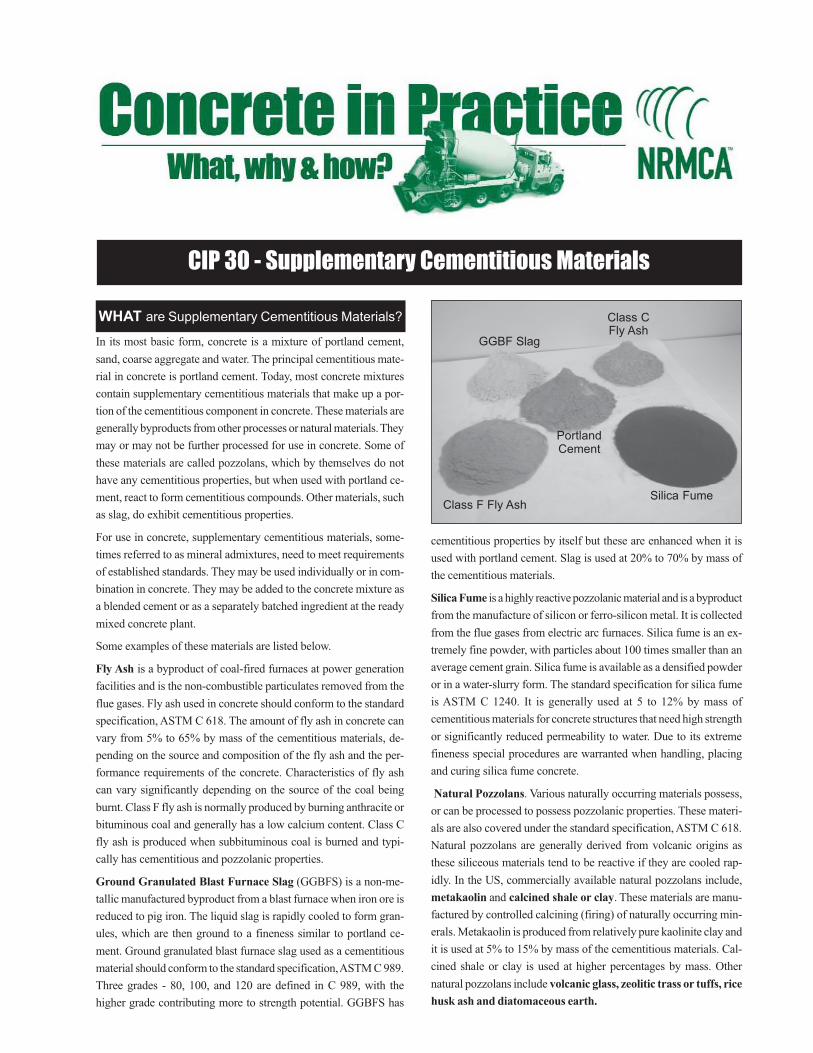
CIP 30 - Supplementary Cementitious Materials
WHAT are Supplementary Cementitious Materials?
Class F Fly Ash
GGBF Slag
PortlandCement
Class CFly Ash
Silica Fume
In its most basic form, concrete is a mixture of portland cement,
sand, coarse aggregate and water. The principal cementitious mate-
rial in concrete is portland cement. Today, most concrete mixtures
contain supplementary cementitious materials that make up a por-
tion of the cementitious component in concrete. These materials are
generally byproducts from other processes or natural materials. They
may or may not be further processed for use in concrete. Some of
these materials are called pozzolans, which by themselves do not
have any cementitious properties, but when used with portland ce-
ment, react to form cementitious compounds. Other materials, such
as slag, do exhibit cementitious properties.
For use in concrete, supplementary cementitious materials, some-
times referred to as mineral admixtures, need to meet requirements
of established standards. They may be used individually or in com-
bination in concrete. They may be added to the concrete mixture as
a blended cement or as a separately batched ingredient at the ready
mixed concrete plant.
Some examples of these materials are listed below.
Fly Ash is a byproduct of coal-fired furnaces at power generation
facilities and is the non-combustible particulates removed from the
flue gases. Fly ash used in concrete should conform to the standard
specification, ASTM C 618. The amount of fly ash in concrete can
vary from 5% to 65% by mass of the cementitious materials, de-
pending on the source and composition of the fly ash and the per-
formance requirements of the concrete. Characteristics of fly ash
can vary significantly depending on the source of the coal being
burnt. Class F fly ash is normally produced by burning anthracite or
bituminous coal and generally has a low calcium content. Class C
fly ash is produced when subbituminous coal is burned and typi-
cally has cementitious and pozzolanic properties.
Ground Granulated Blast Furnace Slag (GGBFS) is a non-me-
tallic manufactured byproduct from a blast furnace when iron ore is
reduced to pig iron. The liquid slag is rapidly cooled to form gran-
ules, which are then ground to a fineness similar to portland ce-
ment. Ground granulated blast furnace slag used as a cementitious
material should conform to the standard specification, ASTM C 989.
Three grades - 80, 100, and 120 are defined in C 989, with the
higher grade contributing more to strength potential. GGBFS has
cementitious properties by itself but these are enhanced when it is
used with portland cement. Slag is used at 20% to 70% by mass of
the cementitious materials.
Silica Fume is a highly reactive pozzolanic material and is a byproduct
from the manufacture of silicon or ferro-silicon metal. It is collected
from the flue gases from electric arc furnaces. Silica fume is an ex-
tremely fine powder, with particles about 100 times smaller than an
average cement grain. Silica fume is available as a densified powder
or in a water-slurry form. The standard specification for silica fume
is ASTM C 1240. It is generally used at 5 to 12% by mass of
cementitious materials for concrete structures that need high strength
or significantly reduced permeability to water. Due to its extreme
fineness special procedures are warranted when handling, placing
and curing silica fume concrete.
Natural Pozzolans. Various naturally occurring materials possess,
or can be processed to possess pozzolanic properties. These materi-
als are also covered under the standard specification, ASTM C 618.
Natural pozzolans are generally derived from volcanic origins as
these siliceous materials tend to be reactive if they are cooled rap-
idly. In the US, commercially available natural pozzolans include,
metakaolin and calcined shale or clay. These materials are manu-
factured by controlled calcining (firing) of naturally occurring min-
erals. Metakaolin is produced from relatively pure kaolinite clay and
it is used at 5% to 15% by mass of the cementitious materials. Cal-
cined shale or clay is used at higher percentages by mass. Other
natural pozzolans include volcanic glass, zeolitic trass or tuffs, rice
husk ash and diatomaceous earth.

2000
Supplementary cementitious materials can be used for improved
concrete performance in its fresh and hardened state. They are pri-
marily used for improved workability, durability and strength. These
materials allow the concrete producer to design and modify the con-
crete mixture to suit the desired application. Concrete mixtures with
high portland cement contents are susceptible to cracking and in-
creased heat generation. These effects can be controlled to a certain
degree by using supplementary cementitious materials.
Supplementary cementitious materials such as fly ash, slag and silica
fume enable the concrete industry to use hundreds of millions of
tons of byproduct materials that would otherwise be landfilled as
waste. Furthermore, their use reduces the consumption of portland
cement per unit volume of concrete. Portland cement has a high
energy consumption and emissions associated with its manufacture,
which is conserved or reduced when the amount used in concrete is
reduced.
Fresh Concrete: In general, supplementary cementitious materials
improve the consistency and workability of fresh concrete because
an additional volume of fines is added to the mixture. Concrete with
silica fume is typically used at low water contents with high range
water reducing admixtures and these mixtures tend to be cohesive
and stickier than plain concrete. Fly ash and slag generally reduce
the water demand for required concrete slump. Concrete setting time
may be retarded with some supplementary cementitious materials
used at higher percentages. This can be beneficial in hot weather.
The retardation is offset in winter by reducing the percentage of
supplementary cementitious material in the concrete. Because of the
additional fines, the amount and rate of bleeding of these concretes
is often reduced. This is especially significant when silica fume is
used. Reduced bleeding, in conjunction with retarded setting, can
cause plastic shrinkage cracking and may warrant special precau-
tions during placing and finishing. (See CIP 5)
Strength - Concrete mixtures can be proportioned to produce the
required strength and rate of strength gain as required for the appli-
cation. With supplementary cementitious materials other than silica
fume, the rate of strength gain might be lower initially, but strength
gain continues for a longer period compared to mixtures with only
portland cement, frequently resulting in higher ultimate strengths.
Silica fume is often used to produce concrete compressive strengths
in excess of 10,000 psi [70 MPa]. Concrete containing supplemen-
tary cementitious material generally needs additional consideration
for curing of both the test specimens and the structure to ensure that
the potential properties are attained.
Durability - Supplementary cementitious materials can be used to
reduce the heat generation associated with cement hydration and
reduce the potential for thermal cracking in massive structural ele-
ments. These materials modify the microstructure of concrete and
reduce its permeability thereby reducing the penetration of water
and water-borne salts into concrete. Watertight concrete will reduce
various forms of concrete deterioration, such as corrosion of rein-
forcing steel and chemical attack. Most supplementary cementitious
materials can reduce internal expansion of concrete due to chemical
reactions such as alkali aggregate reaction and sulfate attack. Resis-
tance to freezing and thawing cycles requires the use of air entrained
concrete. Concrete with a proper air void system and strength will
perform well in these conditions.
The optimum combination of materials will vary for different per-
formance requirements and the type of supplementary cementitious
materials. The ready mixed concrete producer, with knowledge of
the locally available materials, can establish the mixture proportions
for the required performance. Prescriptive restrictions on mixture
proportions can inhibit optimization and economy. While several
enhancements to concrete properties are discussed above, these are
not mutually exclusive and the mixture should be proportioned for
the most critical performance requirements for the job with the avail-
able materials.
WHY are Supplementary Cementitious Materials
Used?
HOW do these Materials Affect Concrete
Properties?
References
1. ASTM Standards C 618, C 989, C 1240, Volume 04.02, American So-
ciety of Testing and Materials, West Conshohocken, PA.
2. Use of Natural Pozzolans in Concrete, ACI 232.1R, American Con-
crete Institute, Farmington Hills, MI.
3. Use of Fly Ash in Concrete, ACI 232.2R, American Concrete Institute,
Farmington Hills, MI.
4. Ground Granulated Blast Furnace Slag as a Cementitious Constituent
in Concrete, ACI 233R, American Concrete Institute, Farmington Hills,
MI.
5. Guide for the Use of Silica Fume in Concrete, ACI 234R, American
Concrete Institute, Farmington Hills, MI.
6. Pozzolanic and Cementitious Materials, V.M. Malhotra and P. Kumar
Mehta, Gordon and Breach Publishers

CIP 31 - Ordering Ready Mixed Concrete
WHAT is Ready Mixed Concrete?
WHY Use Ready Mixed Concrete?
HOW to Order Ready Mixed Concrete?
Concrete is a mixture of cementitious materials, water, aggregate,usually sand and gravel or crushed stone. There is a common mis-understanding that cement and concrete are one and the same. Ce-ment is a powdered ingredient that provides the glue that binds theaggregates together in a mass called concrete.
Ready mixed concrete is that which is delivered to the customer ina freshly mixed and unhardened state. Due to the ability to custom-ize its properties for different applications and its strength and du-rability to withstand a wide variety of environmental conditions,ready mixed concrete is one of the most versatile and popular build-ing materials.
Concrete mixtures are proportioned to obtain the required proper-ties for the application. It should have the correct consistency, orslump, to facilitate handling and placing and adequate strength anddurability to withstand applied loads in the anticipated environ-ment and service conditions. The design quantities of concrete in-gredients are accurately weighed and mixed, either in a mixer at theconcrete plant or in a concrete truck mixer. It is delivered in a truckmixer or agitation unit, which keeps the concrete uniformly mixeduntil it is discharged at the placement location. Concrete remainsplastic for several hours depending on the type of mixture and con-ditions during placement so that there is sufficient time for it to beplaced and finished. Concrete normally sets or hardens within twoto twelve hours after mixing and continues to gain strength formonths or even years if it is properly cured during the first fewdays.
Concrete, in its freshly mixed state, is a plastic workable mixturethat can be cast into virtually any desired shape. The properties ofconcrete can be customized for almost any application to serve in awide variety of extreme environments. Concrete is a very economi-cal building material that can serve its function for several yearswith minimum maintenance, provided the proper mixture relativeto the application and established construction practices are used.A wide variety of options with color, texture and architectural de-tail are available to enhance the aesthetic quality of the concreteapplication.
The key to placing an order for ready mixed concrete is to pro-vide all the basic detailed information and to keep the require-ments as simple as possible and relevant to the application. Theready mixed concrete producer has several mixture formulationsfor a wide variety of applications and can help with deciding therequired mixture characteristics.
Some of the basic requirements to keep in mind when placing aconcrete order are as follows:
Size of coarse aggregate - the important information is the nominal
maximum size required, which should be smaller than the narrowestdimension through which concrete should flow, such as the thick-ness of the section and spacing of the reinforcing steel, if any. Formost applications, nominal maximum size of coarse aggregate is 3/4
or 1 inch (19.0 or 25.0 mm).
Slump - Concrete slump, a measure of its consistency, should beindicated. A stiffer mixture will have a low slump value. Typicalslump range for most applications is 3 to 5 inches (75 to 100 mm).For slip-form construction a maximum slump of 2 inches (50 mm) isrequired, while higher slump to a maximum of 7 inches (175 mm) istypical for basement walls. The tolerance on the slump as deliveredis ±1 to 11/2 inch (25 to 38 mm). Addition of water at the jobsite toincrease slump is permitted, provided it is not excessive enough tocause segregation and reduce strength and durability.
Entrained air - Air entrained concrete should be used if concretewill be exposed to freezing temperatures in service, or even duringconstruction. In many locations air-entrained concrete is the defaultoption. When non air-entrained concrete is required this should beclearly stated at the time of ordering. Target air content depends onthe size of the coarse aggregate and the typical range is 4 to 6% ofthe concrete volume. The tolerance on air content as delivered is±1.5%. The concrete supplier is permitted to make an adjustment forair content at the jobsite if, when tested it is lower than the requiredamount.
Quality level required - The purchaser specifies the concrete quality,in terms of its properties or composition.
The preferred method for ordering concrete is by specifying perfor-mance requirements, which is generally the concrete strength. Otherperformance characteristics, such as permeability, shrinkage or vari-ous durability requirements, may be specified when required. Theproducer should be made aware of anticipated exposure and serviceconditions of the structure. The concrete producer is best equippedto proportion, mix and furnish concrete for the desired performance.The strength level is generally dictated by the design of the structureto withstand anticipated loads during construction and in service. Aminimum strength of 3500 to 4000 psi (25 to 28 MPa) may ensure

2000
WHAT are the Responsibilities?
CAUTION
Fresh concrete can cause severe chemical burns to skin and eyes. Keep fresh concrete off your skin. When working with concrete use rubber work-boots, gloves, protective eyeglasses, clothing and knee-boards. Do not let concrete or other cement products soak into clothing or rub against yourskin. Wash your skin promptly after contact with fresh concrete with clean water. If fresh concrete gets into your eyes, flush immediately andrepeatedly with water and consult a doctor immediately. Keep children away from dry cement powder and all freshly mixed concrete.
durable concrete, such as resistance to wear, abrasion, and freezingand thawing cycles.
Another option is to order concrete by specifying prescriptive re-quirements. The purchaser specifies limits on the quantities and typesof ingredients in the mixture. In this case the purchaser should gen-erally accept responsibility for concrete strength and performance.The prescriptive limits may indicate minimum cement content, maxi-mum water-cement ratio, and limits on the quantities of pozzolans,slag or admixtures. Frequently, this approach is used when a particu-lar prescriptive mixture formulation has worked well in the past.This approach does not allow the producer much flexibility on theeconomy of the mixture or to accommodate changes in materialsources or characteristics that may affect concrete’s performance.
Specifying performance and prescriptive requirements is discour-aged as the performance requirements may conflict with the pre-scriptive limits.
Quantity of concrete - Concrete is sold by volume, in cubic yards(cubic meters), in a freshly mixed unhardened state as dischargedfrom the truck mixer. The delivered volume, or yield, is calculatedfrom the measured concrete density or unit weight. One cubic yardof concrete weighs about 4000 lb. (2 short tons). One cubic meter(approximately 1.3 cubic yards) weighs about 2400 kg. The typicalcapacity of a truck mixer is 8 to 12 cubic yards (5 to 9 cubic meters).
Order about 4% to 10% more concrete than is estimated from a volu-metric calculation of the plan dimensions. This will account for wasteor spillage, over-excavation, spreading of forms, loss of entrainedair during placement, settlement of a wet mixture, truck mixer hold-back and change in volume - hardened concrete volume is 1% to 2%less than that of the fresh concrete. Reevaluate the needs during place-ment and communicate any changes to the concrete supplier.
Disposal of returned concrete has environmental and economicalimplications to the ready mixed concrete producer. Make a goodestimate of concrete required for the job before placing an order.Avoid ordering small clean-up loads, less than 4 cubic yards (2.5cubic meters).
Additional Items - A variety of value-added options are availablefrom the ready mixed concrete producer. Chemical admixtures canaccelerate or retard the setting characteristics of concrete to aid inplacing and finishing during hot or cold weather. Water reducingadmixtures are used to increase concrete slump without adding wa-ter to the concrete. Synthetic fibers can reduce the potential for plas-tic shrinkage cracking. Using color or special aggregates can en-hance aesthetic characteristics. The concrete contractor can also be aresource for innovative finishes and textures to concrete.
Scheduling delivery - Schedule the delivery of concrete to accom-modate the construction schedule. Inform the producer of the cor-rect address, location and nature of the pour, and an estimated deliv-ery time. Call the ready mixed concrete producer well in advance ofthe required delivery date. Concrete is a perishable product and theconstruction crew should be ready for concrete placement when thetruck arrives. Notify the producer of any schedule changes or workstoppage immediately.
Ensure that the truck mixer has proper access to the placement loca-
tion. The concrete truck weighs in excess of 60,000 lbs. (27,000 kg)and may not be able to maneuver on loose dirt and residential curbsand pathways.
The responsibilities of the various parties involved in the construc-tion process should be addressed at a pre-construction meeting, es-pecially on a large job. These responsibilities should be documentedand distributed to all concerned for reference during the construc-tion. Some items are discussed below.
• The concrete producer is responsible for the concrete slump asspecified for a period of 30 minutes after the requested time orthe time the truck arrives at the placement site, whichever is later.
• The concrete producer is required to deliver concrete at the re-quested slump and air content, within the accepted tolerancesaddressed above, as measured at the point of discharge from thetransportation unit.
• When placing procedures can potentially alter the characteris-tics of the fresh concrete, it is the responsibility of the purchaserto inform the producer of changes to the mixture requirements toaccommodate these effects. An example is pumping concrete inplace.
• When a job uses more than one type of concrete mixture, it is thepurchaser’s responsibility to verify the mixture delivered anddirect it to the correct placement location.
• The purchaser should check and sign the delivery ticket and docu-ment any special occurrences on the ticket.
• The concrete producer cannot be responsible for the quality ofconcrete when any modification or additions are made to themixture at the jobsite. These include addition of excessive water,admixtures, fibers or special products, or if the truck has to waitfor an extended period before discharging the concrete.
• When strength tests are used for acceptance of concrete, thesamples should be obtained at the point of discharge from thetransportation unit. The purchaser or his representative shouldensure that proper facilities are available for curing the test speci-mens at the jobsite and that standard practices are followed forsubsequent curing and testing. Certified personnel should con-duct the tests. Test reports should be forwarded to the producerin a timely manner to ensure that deficiencies are rectified.
References
1. ASTM C 94, Standard Specification for Ready Mixed Concrete, Vol.
04.02, American Society for Testing and Materials, West Conshohocken,
PA.
2. Ready Mixed Concrete, Richard D. Gaynor, NRMCA Publication 186,
NRMCA, Silver Spring, MD.
3. Guide for Measuring, Mixing, Transporting and Placing Concrete, ACI
304R, American Concrete Institute, Farmington Hills, MI

CIP 32 - Concrete Pre-Construction Conference
WHAT is a Pre-Construction Conference?
WHY Have a Pre-Construction Conference?
Prior to the start of a job, especially for a major project, a
concrete pre-construction conference (some times called a
pre-pour meeting) should be held to define and allocate re-
sponsibilities of the entire construction team. It is imperative
that all members of the team meet to establish the responsi-
bilities of the ready mixed concrete supplier, owner, archi-
tect, structural engineer, general contractor, sub contractors,
testing agencies, and inspectors. This meeting should be held
well in advance of the project to ensure there is sufficient
time for all parties to be absolutely clear on what their re-
sponsibilities would entail.
Every construction project brings together different compa-
nies, personnel and procedures, who may or may not have
worked together before. Two jobs are never the same, even
when working with the same companies, as personnel changes
can realign the perception of individual responsibilities. Pre-
construction conferences are needed to sort out the details of
how a job will be executed, identify the authorized contacts
for various aspects, and what should be done if some things
do not go as planned. In far too many cases, projects are started
without a clear understanding of assigned responsibilities re-
sulting in extra work, lost time and major expenses. In some
cases a simple pre-construction conference could have pre-
vented some, if not all these problems from occurring. Having
this meeting serves to document the chain of responsibilities,
which can be referenced when needed.
HOW to Conduct a Pre-Construction
Conference?
The pre-construction conference agenda should contain the
following to ensure that all details are addressed prior con-
crete placement.
Purpose: To define and allocate individual responsibilities
of the concrete construction team
Subject: Pre-construction agenda, concrete mix designs,
placement, inspection and testing
Project Name and Location: Establish the project name and
address.
Personnel to Attend: Contractor’s project manager, owner’s
representative, concrete subcontractor, architect, engineer, test-
ing lab supervisor, pumping contractor, concrete producer’s
quality control director, inspector and construction manager,
if applicable, and anyone else with the need to know.
Minutes of the Meeting: Assign someone to take minutes.
Establish a meeting distribution list.
Concrete Mix Design and Specifications: Have the mix de-
signs been approved and what is the approval process? Are
there any special concrete performance requirements or con-
ditions? Are value-added admixtures approved for use and
who can authorize them?
Ordering Concrete and Scheduling Deliveries: Ensure that
concrete delivery schedules are in place. Establish the lead-
time needed to place the order, especially for large placements
or special concrete, and establish links of communication for
last minute cancellations. Establish who has the authority to
place and cancel concrete orders. Establish truck staging ar-
eas and location to wash out trucks and disposing of excess
concrete.
Plant Inspections: Are plant inspections required? If so who
will do the inspections and what will it entail. Will an NRMCA
certification be accepted?
Job Inspections: Who is responsible for inspection and ap-
proval of forms and rebar prior to concrete placement? Who
is responsible for approving adequacy of subgrade prepara-
tion for concrete slabs on grade? Who is responsible for plac-
ing and consolidation of concrete? Who will ensure that proper
2000
References
1. Ready Mixed Concrete Quality Control Checklist, Quality Con-
trol Manual - Section 1, NRMCA, Silver Spring, MD.
2. Concrete Pre-Construction Checklist, Georgia Concrete &
Products Association, 1st Edition.
3. NRMCA-ASCC Checklist for the Concrete Pre-Construction
Conference, NRMCA, Silver Spring, MD.
methods of finishing and curing are employed? What method
will be used and for how long will concrete be cured? What is
the minimum concrete strength required for stripping form?
Will there be a formal report form for stripping forms? Will
there be any in-place strength testing? Who is responsible to
authorize form removal? Where will field-cured cylinders be
stored and for what purpose will they be tested?
Sampling and Testing: What procedure will be followed for
acceptance samples? What is the frequency for sampling and
testing concrete? Will concrete be sampled as it is discharged
from the truck mixer or at another location? What tests will be
performed? Who will conduct the testing and who will verify
that the technicians are certified? How many test cylinders will
be made, how will they be cured, and at what ages will they be
tested? What procedure is followed for non-conformance to
specification?
Acceptance and Rejection Responsibilities for Fresh Con-
crete: Who has the authority to add water to the concrete on
site? Who has the authority to reject concrete delivery? For
what reasons can concrete be rejected? What are the toler-
ances for slump, air content, unit weight, and temperature?
Establish re-test procedures for concrete prior to rejection.
Specimen Handling: How will cylinders be stored at the
jobsite? Who is required to provide the initial curing environ-
ment for the test cylinders and how will controlled tempera-
ture and moisture be maintained? How will test cylinders be
transported on weekends or non-workdays and who will ar-
range for access on to the site? What curing procedure is used
at the testing facility? Verify that cylinders will be handled,
transported and cured in accordance with ASTM C 31, or other
applicable standards.
Report Distribution and Acceptance Criteria: Define the
time frame for the report distribution and who will get copies
of test reports. What will be on the reports and what will be the
strength acceptance criteria: ACI 318, ASTM C 94 or other?
Testing of In-Place Concrete: The meeting should address
what situations will require additional testing. How will the
test results be evaluated, and by whom? Who incurs the ex-
pense for additional evaluations?
The items listed above are examples of some of the issues that
should be discussed at a pre-construction conference. It also
provides the opportunity for all involved parties to thoroughly
review the specification and contract documents and if neces-
sary make changes and improvements to them. It will also pro-
vide an understanding of responsibilities, which should be docu-
mented, for future reference.
SUGGESTED PRE-CONSTRUCTION CONFERENCE AGENDA ITEMS
• Project information and schedule
• Project participants
• Construction sequence andprocesses
• Base/subgrade construction andacceptance
• Site access
• Power, lighting, water
• Formwork and removal
• Placing concrete - equipment andprocedures
• Vapor retarders/barriers
• Consolidation
• Finishing
• Requirements for surface finishes
• Jointing
• Curing and sealing
• Protection of concrete
• Hot and cold weather precautions
• Concrete materials and mixtures
• Specification requirements for concrete
• Jobsite adjustments
• Special materials
• Ordering and scheduling concretedelivery
• Quality control / Quality assurance
• Report distribution
• Corrective actions
• Test specimen storage,transportation and testing
• Acceptance/rejection of fresh andhardened concrete
• In-place concrete strength evaluation
• Dispute resolution and costassignment
• Jobsite environmental management
• Jobsite safety

CIP 33 - High Strength Concrete
WHAT is High Strength Concrete?
WHY do We Need High Strength Concrete?
Testing High Strength Concrete
HOW to Design High-Strength Concrete Mixture?
It is a type of high performance concrete generally with
a specified compressive strength of 6,000 psi (40 MPa)
or greater. The compressive strength is measured on 6 ×12 inch (150 × 300 mm) or 4 × 8 inch (100 × 200 mm)
test cylinders generally at 56 or 90-days or some other
specified age depending upon the application. The pro-
duction of high strength concrete requires more research
and more attention to quality control than conventional
concrete.
A. To put the concrete into service at much earlier age,
for example opening the pavement at 3-days.
B. To build high-rise buildings by reducing column
sizes and increasing available space.
C. To build the superstructures of long-span bridges
and to enhance the durability of bridge decks.
D. To satisfy the specific needs of special applications
such as durability, modulus of elasticity, and flex-
ural strength. Some of these applications include
dams, grandstand roofs, marine foundations, park-
ing garages, and heavy duty industrial floors. (Note
that high strength concrete does not guarantee du-
rable concrete.)
Optimum concrete mixture design results from select-
ing locally available materials that make the fresh con-
crete placeable and finishable and that ensure the strength
development and other desired properties of hardened
concrete as specified by the designer. Some of the basic
concepts that need to be understood for high strength
concrete are:
1. Aggregates should be strong and durable. They need
not necessarily be hard and of high strength but need
to be compatible, in terms of stiffness and strength,
with the cement paste. Generally smaller maximum
size coarse aggregate is used for higher strength con-
cretes. The sand may have to be coarser than that
permitted by ASTM C 33 (fineness modulus greater
that 3.2) because of the high fines content from the
cementitious materials.
2. High strength concrete mixtures will have a high
cementitious materials content that increases the heat
of hydration and possibly higher shrinkage leading
to the potential for cracking. Most mixtures contain
one or more supplementary cementitious materials
such as fly ash (Class C or F), ground granulated
blast furnace slag, silica fume, metakaolin or natu-
ral pozzolanic materials.
3. High strength concrete mixtures generally need to
have a low water-cementitious materials ratio (w/
cm). W/cm ratios can be in the range of 0.23 to 0.35.

2001
These low w/cm ratios are only attainable with quite
large doses of high range water reducing admixtures
(or superplasticizers) conforming to Type F or G by
ASTM C 494. A Type A water reducer may be used
in combination.
4. The total cementitious material content will be typi-
cally around 700 lbs/yd3 (415 kg/m3) but not more
than about 1100 lbs/yd3 (650 kg/m3).
5. The use of air entrainment in high strength concrete
will greatly reduce the strength potential.
More attention and evaluation will be necessary if the
job specification sets limits for other concrete properties
such as creep, shrinkage, and modulus of elasticity. The
engineer may set limits on these properties for the de-
sign of the structure. Current research may not provide
the required guidance for empirical relationships of these
properties from traditional tests and some of these tests
are quite specialized and expensive to conduct for mix-
ture evaluation. From theoretical considerations, lower
creep and shrinkage, and high modulus of elasticity can
be achieved with higher aggregate and lower paste vol-
umes in the concrete. Using the largest size aggregate
possible and medium to coarsely graded fine aggregate
can attain this. Smaller maximum size aggregate such as
3/8 inch (9.5mm) can be used to produce very high com-
pressive strength but required properties like creep,
shrinkage, and modulus of elasticity may be sacrificed.
If difficulty is encountered in achieving high strength,
simply adding more cementitious material may not in-
crease strength. Factors such as deleterious materials in
aggregates, aggregate coatings, coarse aggregate fracture
faces, shape and texture, and testing limitations may pre-
vent higher strength from being achieved. Final concrete
mixture proportions are determined by trial batches ei-
ther in the laboratory or by small size field production
batches. The production, transportation, placement and
finishing of high-strength concrete can differ significantly
from procedures used for conventional concrete. For criti-
cal projects it is highly recommended that a trial pour
and evaluation be conducted and included as a pay item
in the contract. Pre-bid and pre-construction meetings
are very important to ensure the success of projects us-
ing high strength concrete. During construction, extra
measures should be taken to protect against plastic shrink-
age and thermal cracking in thicker sections. High
strength concrete may need longer time before formwork
is removed.
High strength concrete test cylinders should be carefully
molded, cured, capped, and tested. Extra care and atten-
tion to handling of test cylinder specimens at very early
age is necessary. Slower setting time of high strength
concretes may be experienced. The ASTM Standards are
continuously being revised to account for additional spe-
cial precautions needed when testing high strength con-
crete. Particular attention should be paid to the type of
mold, curing, type of cylinder capping material, and char-
acteristics and load capacity of the testing machine.
References
1. State-of-the-Art Report on High Strength Concrete, ACI
363R, ACI International, Farmington Hills, MI, www.aci-
int.org.
2. Guide to Quality Control and Testing of High Strength
Concrete, ACI 363.2R, ACI International Farmington
Hills, MI.
3. Creating a balanced mix design for high strength con-
crete, Bryce Simons, The Concrete Producer, October
1995, www.worldofconcrete.com.
4. Getting Started with High-strength Concrete, Ron Burg,
The Concrete Producer, November 1993.
5. Effects of Testing Variables on the Measured Compres-
sive Strength of High Strength (90 MPa) Concrete, Nick
J. Carino, et al., NISTIR 5405, October 1994, National
Institute of Standards and Technology, Gaithesburg, MD,
www.nist.gov.
6. 10,000 psi Concrete, James E. Cook, ACI Concrete Inter-
national, October 1989, ACI International, Farmington
Hills, MI.

CIP 34 - Making Concrete Cylinders In the Field
WHAT are Concrete Test Cylinders?
WHY Make Concrete Test Cylinders?
HOW to Make & Cure Cylinders?
Making and Curing Cylinders in the Field
Most commonly, the compressive strength of concrete is measuredto ensure that concrete delivered to a project meets the requirementsof the job specification and for quality control. For testing the com-pressive strength of concrete, cylindrical test specimens of size 4 ´8-inch (100 ´ 200-mm) or 6 ´ 12-inch (150 ́300-mm) are cast andstored in the field until the concrete hardens in accordance with therequirements of ASTM C 31, Standard Practice for Making andCuring Concrete Test Specimens in the Field.
Most specifications require that technicians certified by the ACIField Testing Certification Grade I, or an equivalent program maketest specimens in the field. When making cylinders for acceptanceof concrete, the field technician must test other properties of thefresh concrete to include temperature, slump, density (unit weight)and air content. This information should accompany the set of cyl-inders made for a particular pour or pour location. A strength testresult is always the average of at least two specimens tested at thesame age. A set of 2 to 6 cylinders may be made from the samesample of concrete at a minimum for every 150 cubic yards (115m3) of concrete placed.
According to ASTM C 31, the results of standard-cured cylindersare used for
· Acceptance testing for specified strengths,· Verifying mixture proportions for strength,· Quality control by the concrete producer
It is of prime importance that the specimens are made and curedfollowing standard procedures. Any deviation from standard proce-dures will result in a lower measured strength. Low strength testresults due to procedures not in accordance with the standards causeundue concern, cost and delay to the project.
The strength results of field-cured cylinders are used for
· Determining the time at which a structure is permitted to be putinto service,
· Evaluating the adequacy of curing and protecting concrete inthe structure, and
· Scheduling removal of forms or shoring
Curing requirements for field-cured cylinders are different from stan-dard curing and the two should not be confused. Refer to ASTM C31 for details on curing field-cured specimens.
Equipment needed at the job site:
· Molds for casting cylinder specimens. Plastic molds are mostcommon.
· Tamping rod with hemispherical tip - 5/8-inch (15-mm) diam-
eter for 6 ´ 12-inch cylinders or 3/8-inch (10-mm) diameter for 4´ 8-inch cylinders, or a vibrator
· Rubber or rawhide mallet, 1.25 ± 0.50 lb. (0.6 ± 0.2 kg)
· Shovel, hand-held wooden float, and scoop,
· Wheelbarrow or other appropriate sample container,
· Water tank or curing box with provisions to maintain requiredcuring environment during initial curing period.
· Safety equipment as appropriate to handle freshly mixed con-crete.
Sampling concrete from a ready mixed concrete truck:
It is very important to obtain a sample of concrete that is repre-
sentative of the concrete in the truck mixer. Sampling from con-crete delivery units should be conducted in accordance with ASTM
C 172 Standard Practice for Sampling Freshly Mixed Concrete.
Concrete should be sampled from the middle of the load. The firstor last discharge from the load will not provide a representative
sample. The concrete must be sampled by diverting the chute into
a wheelbarrow so that the entire discharge stream is collected. Atleast two portions during discharge are necessary to obtain a com-
posite sample. The time elapsed between the first and final por-
tion of the composite sample must not exceed 15 minutes. Theminimum required size of the concrete sample is 1 cu. ft. (28 L).

2001
Prior to Casting Cylinders:
Cover the sample with a plastic sheet to protect the concrete from
evaporation, sunlight, and contamination. Move the sample tothe location where the fresh concrete tests are to be conducted.
The testing location should be close to where the cylinders will
be stored undisturbed for the initial curing period. After the con-crete is transported to the location for casting the cylinders, re-
mix the concrete in the wheelbarrow. Begin the slump, density
(unit weight), and air content tests within 5 minutes and startmolding cylinders within 15 minutes after the sample was ob-
tained.
Casting the Test Cylinders:
· Label the outside of the mold with the appropriate identificationmark. Do not label the lids or tops.
· Place the cylinder molds on a level surface· Determine the method of consolidation
1. For concrete with slump less than 1-inch (25-mm), con-crete should be consolidated by vibration
2. For concrete with slump 1-inch (25-mm) or higher, either
rodding or vibrating is permitted.
· Determine the number of layers of concrete to be placed in themold
1. For concrete to be consolidated with the tamping rod, placeconcrete in 3 equal layers for 6 ́ 12-inch cylinders; and in
2 equal layers for 4 ´ 8-inch cylinders
2. For concrete to be consolidated by vibration, fill the mold
in two equal layers.· Place the concrete in the mold by distributing it around the in-
side of the mold with the scoop. Consolidate the layer by rodding25 times evenly distributed around the layer. When using a vi-brator, insert it long enough so the surface is smooth and largeair pockets ceases to break through to the top. Two insertions ofthe vibrator are required for a 6 ´ 12-inch and one insertion isrequired for a 4 ´ 8-inch cylinders. Avoid over vibration.
· Tap the sides of the mold 10-15 times with the mallet after eachlayer in order to close any insertion holes formed either by therod or the vibrator.
· Strike off the top with a wooden float to produce a flat, even andlevel surface and cover with a plastic lid or a plastic bag.
Storing and transporting test cylinders:· Move cylinder molds with fresh concrete very carefully by sup-
porting the bottom· Place the cylinders on a flat surface and in a controlled environ-
ment where the temperature is maintained in the range of 60 to80°F (16 to 27°C). When the specified strength of the concrete is
greater than 6000 psi (40 MPa), the temperature range for initialcuring should be maintained in the range of 68 to 78°F (20 to26°C). Immersing cylinders, completely covered in water is anacceptable and preferred procedure that ensures more reliablestrength results. Temperature in storage, such as in curing boxes,should be controlled using heating and cooling devices as nec-essary. The maximum and minimum temperature during initialcuring should be recorded and reported.
· Protect cylinders from direct sunlight or radiant heat and fromfreezing temperatures in winter.
· Cylinders must be transported back to the laboratory within 48hours of casting. Some concrete mixtures may take longer to setand these specimens may be transported at a later time. In anyevent cylinders should not be moved or transported until at least8 hours after final set.
Store cylinders to prevent damage and maintain moisture during trans-portation. Travel time from the jobsite to the laboratory should notexceed 4 hours.
References
1. Annual Book of ASTM Standards, Volume 04.02 Concrete and Ag-
gregates, ASTM, West Conshohocken, PA, www.astm.org
· ASTM C 31. Standard Practice for Making and Curing Concrete
Test Specimens in the Field
· ASTM C 39, Standard Test Method for Compressive Strength of
Cylindrical Concrete Specimens
· ASTM C 172, Standard Practice for Sampling Freshly Mixed Con-
crete
· ASTM C 617, Standard Practice for Capping Cylindrical Concrete
Specimens
2. How Producers can Correct Improper Test-Cylinder Curing, Ward R.
Malisch, The Concrete Producer, Nov 1997, pp. 782 – 805,
www.worldofconcrete.com
3. NRMCA/ASCC Checklist for Concrete Pre-Construction Conference,
NRMCA, Silver Spring, MD, www.nrmca.org
CAUTION
Fresh concrete can cause severe chemical burns to skin and eyes. Keep
fresh concrete off your skin. When working with concrete use rubber work-
boots, gloves, protective eyeglasses and clothing. Do not let concrete or
other cement-based products soak into clothing or rub against your skin.
Wash your skin promptly after contact with fresh concrete with clean wa-
ter. If fresh concrete gets into your eyes, flush immediately and repeat-
edly with water. Consult a doctor immediately. Keep children away from
all freshly mixed plastic concrete.
Follow These Rules to Make and Cure Standard Cured Strength Test Specimens1. Obtain a representative concrete sample
2. Place the concrete in layers in the molds and consolidate using standard equipment and procedures
3. Finish the surface smooth and cover the cylinder with a cap or plastic bag
4. For initial curing, store cylinders in the required temperature range. Protect from direct sunlight or extreme weather.
5. Transport the cylinders to the laboratory with proper protection within 48 hours after they are made.

CIP 35 - Testing Compressive Strength of Concrete
WHAT is the Compression Strength of Concrete?
WHY is Compressive Strength Determined?
Concrete mixtures can be designed to provide a wide range of me-
chanical and durability properties to meet the design requirements
of a structure. The compressive strength of concrete is the most
common performance measure used by the engineer in designing
buildings and other structures. The compressive strength is mea-
sured by breaking cylindrical concrete specimens in a compression-
testing machine. The compressive strength is calculated from the
failure load divided by the cross-sectional area resisting the load
and reported in units of pound-force per square inch (psi) in US
Customary units or megapascals (MPa) in SI units. Concrete com-
pressive strength requirements can vary from 2500 psi (17 MPa)
for residential concrete to 4000 psi (28 MPa) and higher in com-
mercial structures. Higher strengths up to and exceeding 10,000
psi (70 MPa) are specified for certain applications.
Compressive strength test results are primarily used to determine
that the concrete mixture as delivered meets the requirements of the
specified strength, ƒ′c, in the job specification.
Strength test results from cast cylinders may be used for quality
control, acceptance of concrete, or for estimating the concrete strength
in a structure for the purpose of scheduling construction operations
such as form removal or for evaluating the adequacy of curing and
protection afforded to the structure. Cylinders tested for acceptance
and quality control are made and cured in accordance with procedures
described for standard-cured specimens in ASTM C 31 Standard
Practice for Making and Curing Concrete Test Specimens in the
Field. For estimating the in-place concrete strength, ASTM C 31
provides procedures for field-cured specimens. Cylindrical
specimens are tested in accordance with ASTM C 39, Standard Test
Method for Compressive Strength of Cylindrical Concrete
Specimens.
A test result is the average of at least two standard-cured strength
specimens made from the same concrete sample and tested at the
same age. In most cases strength requirements for concrete are at an
age of 28 days.
Design engineers us the specified strength ƒ´cto design structural
elements. This specified strength is incorporated in the job contract
documents. The concrete mixture is designed to produce an average
strength, ƒ′cr, higher than the specified strength such that the risk of
not complying with the strength specification is minimized. To
comply with the strength requirements of a job specification both
the following acceptance criteria apply:
• The average of 3 consecutive tests should equal or exceed the
specified strength, ƒ´c
• No single strength test should fall below ƒ´cby more than
500 psi (3.45 MPa); or by more than 0.10 ƒ´c when
ƒ´c is more than 5000 psi (35 MPa)
It is important to understand that an individual test falling
below ƒ´c does not necessarily constitute a failure to meet
specification requirements. When the average of strength tests
on a job are at the required average strength, ƒ′cr, the
probability that individual strength tests will be less than the
specified strength is about 10% and this is accounted for in
the acceptance criteria.
When strength test results indicate that the concrete delivered
fails to meet the requirements of the specification, it is
important to recognize that the failure may be in the testing,
not the concrete. This is especially true if the fabrication,
handling, curing and testing of the cylinders are not conducted
in accordance with standard procedures. See CIP 9, Low
Concrete Cylinder Strength.
Historical strength test records are used by the concrete
producer to establish the target average strength of concrete
mixtures for future work.

2003
HOW to Test the Strength of Concrete?
• Cylindrical specimens for acceptance testing should be 6 x 12
inch (150 x 300 mm) size or 4 x 8 inch (100 x 200 mm) when
specified. The smaller specimens tend to be easier to make and
handle in the field and the laboratory. The diameter of the
cylinder used should be at least 3 times the nominal maximum
size of the coarse aggregate used in the concrete.
• Recording the mass of the specimen before capping provides
useful information in case of disputes.
• To provide for a uniform load distribution when testing, cylinders
are capped generally with sulfur mortar (ASTM C 617) or
neoprene pad caps (ASTM C 1231). Sulfur caps should be
applied at least two hours and preferably one day before testing.
Neoprene pad caps can be used to measure concrete strengths
between 1500 and 7000 psi (10 to 50 MPa). For higher strengths
upto 12,000 psi, neoprene pad caps are permitted to be used if
they are qualified by companion testing with sulfur caps.
Durometer hardness requirements for neoprene pads vary from
50 to 70 depending on the strength level tested. Pads should be
replaced if there is excessive wear.
• Cylinders should not be allowed to dry out prior to testing.
• The cylinder diameter should be measured in two locations at
right angles to each other at mid-height of the specimen and
averaged to calculate the cross-sectional area. If the two
measured diameters differ by more than 2%, the cylinder should
not be tested.
• The ends of the specimens should not depart from perpendicularity
with the cylinder axis by more than 0.5º and the ends should be
plane to within 0.002 inches (0.05 mm).
• Cylinders should be centered in the compression-testing machine
and loaded to complete failure. The loading rate on a hydraulic
machine should be maintained in a range of 20 to 50 psi/s (0.15
to 0.35 MPa/s) during the latter half of the loading phase. The
type of break should be recorded. A common break pattern is a
conical fracture (see figure).
• The concrete strength is calculated by dividing the maximum
load at failure by the average cross-sectional area. C 39 has
correction factors if the length-to-diameter ratio of the cylinder
is between 1.75 and 1.00, which is rare. At least two cylinders
are tested at the same age and the average strength is reported
as the test result to the nearest 10 psi (0.1 MPa)
• The technician carrying out the test should record the date they
were received at the lab, the test date, specimen identification,
cylinder diameter, test age, maximum load applied, compressive
strength, type of fracture, and any defects in the cylinders or
caps. If measured, the mass of the cylinders should also be noted.
• Most deviations from standard procedures for making, curing
and testing concrete test specimens will result in a lower
measured strength.
• The range between companion cylinders from the same set and
tested at the same age should be, on average, about 2 to 3% of
the average strength. If the difference between two companion
cylinders exceeds 8% too often, or 9.5% for three companion
cylinders, the testing procedures at the laboratory should be
evaluated and rectified.
• Results of tests made by different labs on the same concrete
sample should not differ by more than about 13% of the average
of the two test results.
• If one or both of a set of cylinders break at strength below ƒ´c,
evaluate the cylinders for obvious problems and hold the tested
cylinders for later examination. Frequently the cause of a failed
test can be readily seen in the cylinder, either immediately or by
petrographic examination. If it is thrown away an easy
opportunity to correct the problem may be lost. In some cases
additional reserve cylinders are made and can be tested if one
cylinder of a set broke at a lower strength.
• A 3 or 7-day test may help detect potential problems with
concrete quality or testing procedures at the lab but is not a
basis for rejecting concrete, with a requirement for 28-day or
other age strength.
• ASTM C 1077 requires that laboratory technicians involved in
testing concrete must be certified.
• Reports of compressive strength tests provide valuable information
to the project team for the current and future projects. The reports
should be forwarded to the concrete producer, contractor and
the owner’s representative as expeditiously as possible.
References
1. ASTM C 31, C 39, C 617, C 1077, C 1231, Annual Book of ASTMStandards, Volume 04.02, ASTM, West Conshohocken, PA,
www.astm.org2. Concrete in Practice Series, NRMCA, Silver Spring, MD,
www.nrmca.org3. In-Place Strength Evaluation - A Recommended Practice, NRMCA
Publication 133, NRMCA RES Committee, NRMCA, Silver Spring,MD
4. How producers can correct improper test-cylinder curing, Ward R.Malisch, Concrete Producer Magazine, November 1997,www.worldofconcrete.com
5. NRMCA/ASCC Checklist for Concrete Pre-Construction Conference,
NRMCA, Silver Spring, MD6. Review of Variables That Influence Measured Concrete Compressive
Strength, David N. Richardson, NRMCA Publication 179, NRMCA,Silver Spring, MD
7. Tips on Control Tests for Quality Concrete, PA015, Portland CementAssociation, Skokie, IL, www.cement.org
8. ACI 214, Recommended Practice for Evaluation of Strength TestsResults of Concrete, American Concrete Institute, Farmington Hills,
MI, www.concrete.org

CIP 36 - Structural Lightweight Concrete
WHAT is Structural Lightweight Concrete?
WHY Use Structural Lightweight Concrete?
Sprinkling Aggregate in a Stockpile
HOW is Structural Lightweight Concrete Used?
Structural lightweight concrete has an in-place density (unit
weight) on the order of 90 to 115 lb/ ft3 (1440 to 1840 kg/m3)
compared to normalweight concrete with a density in the range
of 140 to 150 lb/ ft3 (2240 to 2400 kg/m3). For structural
applications the concrete strength should be greater than 2500
psi (17.0 MPa). The concrete mixture is made with a
lightweight coarse aggregate. In some cases a portion or the
entire fine aggregate may be a lightweight product.
Lightweight aggregates used in structural lightweight concrete
are typically expanded shale, clay or slate materials that have
been fired in a rotary kiln to develop a porous structure. Other
products such as air-cooled blast furnace slag are also used.
There are other classes of non-structural lightweight concretes
with lower density made with other aggregate materials and
higher air voids in the cement paste matrix, such as in cellular
concrete. These are typically used for their insulation
properties. This CIP focuses on structural lightweight
concrete.
The primary use of structural lightweight concrete is to reduce
the dead load of a concrete structure, which then allows the
structural designer to reduce the size of columns, footings
and other load bearing elements. Structural lightweight
concrete mixtures can be designed to achieve similar strengths
as normalweight concrete. The same is true for other
mechanical and durability performance requirements.
Structural lightweight concrete provides a more efficient
strength-to-weight ratio in structural elements. In most cases,
the marginally higher cost of the lightweight concrete is offset
by size reduction of structural elements, less reinforcing steel
and reduced volume of concrete, resulting in lower overall
cost.
In buildings, structural lightweight concrete provides a higher
fire-rated concrete structure. Structural lightweight concrete
also benefits from energy conservation considerations as it
provides higher R-values of wall elements for improved
insulation properties. The porosity of lightweight aggregate
provides a source of water for internal curing of the concrete
that provides continued enhancement of concrete strength and
durability. This does not preclude the need for external curing.
Structural lightweight concrete has been used for bridge
decks, piers and beams, slabs and wall elements in steel and
concrete frame buildings, parking structures, tilt-up walls,
topping slabs and composite slabs on metal deck.
Lightweight concrete can be manufactured with a combina-
tion of fine and coarse lightweight aggregate or coarse light-
weight aggregate and normalweight fine aggregate. Complete
replacement of normalweight fine aggregate with a light-
weight aggregate will decrease the concrete density by ap-
proximately 10 lb/ft3 (160 kg/m3).
Designers recognize that structural lightweight concrete will
not typically serve in an oven-dry environment. Therefore,
structural design generally relies on an equilibrium density
(sometimes referred to as air-dry density); the condition in
which some moisture is retained within the lightweight
concrete. Equilibrium density is a standardized value intended
to represent the approximate density of the in-place concrete
when it is in service. Project specifications should indicate
the required equilibrium density of the lightweight concrete.
Equilibrium density is defined in ASTM C 567, and can be
calculated from the concrete mixture proportions. Field
acceptance is based on measured density of fresh concrete in
accordance with ASTM C 138. Equilibrium density will be
approximately 3 to 8 lb/ ft3 (50 to 130 kg/m3) less than the
fresh density and a correlation should be agreed upon prior
to delivery of concrete. The tolerance for acceptance on fresh
density is typically ±3 lb/ ft3 (±50 kg/m3) from the target value.

2003
Guidelines For Pumping
Lightweight concrete placements frequently employ pumps and this can be done successfully when a few precautions are consid-
ered prior to the actual placement.
1. Aggregate should be adequately pre-soaked as pressure during pumping will drive water into the aggregate pores and
cause slump loss that may result in plugging of the pump line and difficulties in placement and finishing.
2. Pump lines should be as large as possible, preferably 5-inch (125-mm) diameter, with a minimum number of elbows,
reducers or rubber hose sections.
3. The lowest practical pressure should be used.
4. Pump location should be such that vertical fall of the concrete is minimized.
5. Adjustments to mixture characteristics, such as slump, aggregate content and air content may be necessary to ensure
adequate pumpability for the job conditions.
6. Decide on where concrete samples for acceptance tests will be taken and what implications this would have on the con-
crete mixture proportions and properties as delivered to the jobsite.
Lightweight aggregates must comply with the requirements
of ASTM Specification C 330. Due to the cellular nature of
lightweight aggregate particles absorption typically is in the
range of 5% to 20% by weight of dry aggregate. Lightweight
aggregates generally require wetting prior to use to achieve a
high degree of saturation. Some concrete producers may not
have the capability of prewetting lightweight aggregates in
cold weather if temperature controlled storage is not available.
Some lightweight aggregate suppliers furnish vacuum
saturated aggregate.
With the exception of bridges and marine structures,
specifications for structural lightweight concrete do not
typically have a requirement for maximum water-to-
cementitious materials (w/cm) ratio. The w/cm ratio of
structural lightweight concrete cannot be precisely determined
because of the difficulty in determining the absorption of
lightweight aggregate.
Air content of structural lightweight concrete must be closely
monitored and controlled to ensure that the density
requirements are being achieved. Testing for air content must
be according to the volumetric method, ASTM C 173, or
calculated using the gravimetric method described in ASTM
C 138. Virtually all lightweight concrete is air-entrained.
Finishing lightweight concrete requires proper attention to
detail. Excessive amounts of water or excessive slump will
cause the lightweight aggregate to segregate from the mortar.
Bullfloating will generally provide an adequate finish. If the
surface for an interior floor is to receive a hard troweled finish,
use precautions to minimize the formation of blisters or
delaminations. See CIPs 13 and 20 for discussions on blisters
and delaminations, respectively.
Due to the inherent higher total moisture content of lightweight
concrete it typically takes a longer time than normalweight
concrete to dry to levels that might be considered adequate
for application of floor covering materials.
The splitting tensile strength of lightweight concrete is used
in structural design criteria. The design engineer may request
the information for a particular source of lightweight
aggregate prior to the design. The splitting tensile strength
corresponding to the specified compressive strength is
determined in laboratory evaluations. Splitting tensile
strength testing is not used as a basis for field acceptance of
concrete.
Ensure that the requirements of the designer relative to fire
resistance or insulation properties of lightweight concrete
building elements are in conformance with applicable
industry standards. For a successful project, information is
available from the supplier of lightweight aggregate and the
ready mixed concrete producer. With proper planning,
structural lightweight concrete can provide an economical
solution to many engineering applications.
References1. Guide for Structural Lightweight Aggregate Concrete, ACI
213R, American Concrete Institute, Farmington Hills,
MI, www.concrete.org.
2. Guide for Determining the Fire Endurance of Concrete Ele
ments, ACI 216R, American Concrete Institute, Farmington
Hills, MI
3. ASTM C 94, C 138, C 173, C 330 and C 567, Annual Book
of ASTM Standards, Volume 04.02, ASTM International,
West Conshohocken, PA, www.astm.org.
4. Lightweight Concrete and Aggregates, Tom Holm, ASTM
169C, Chapter 48, ASTM International, West Conshohocken,
PA
5. Pumping Structural Lightweight Concrete, Info Sheet
#4770.1, Expanded Shale Clay and Slate Institute, Salt Lake
City, Utah, www.escsi.org

HOW is SCC Achieved?
CIP 37 - Self Consolidating Concrete (SCC)
Figure 1 SCC with a slump flow of 29” (735
mm) as tested by the slump flow test
Self consolidating concrete (SCC), also known as self com-
pacting concrete, is a highly flowable, non-segregating
concrete that can spread into place, fill the formwork and
encapsulate the reinforcement without any mechanical
consolidation. The flowability of SCC is measured in terms
of spread when using a modified version of the slump test
(ASTM C 143). The spread (slump flow) of SCC typically
ranges from 18 to 32 inches (455 to 810 mm) depending
on the requirements for the project. The viscosity, as visu-
ally observed by the rate at which concrete spreads, is an
important characteristic of plastic SCC and can be con-
trolled when designing the mix to suit the type of applica-
tion being constructed.
WHY is SCC Used?
WHAT is Self Consolidating Concrete
(SCC)?
Some of the advantages of using SCC are:
1. Can be placed at a faster rate with no mechanical vi-
bration and less screeding, resulting in savings in place-
ment costs.
2. Improved and more uniform architectural surface fin-
ish with little to no remedial surface work.
3. Ease of filling restricted sections and hard-to-reach
areas. Opportunities to create structural and architec-
tural shapes and surface finishes not achievable with
conventional concrete.
4. Improved consolidation around reinforcement and
bond with reinforcement
5. Improved pumpability.
6. Improved uniformity of in-place concrete by elimi-
nating variable operator-related effort of consolida-
tion.
7. Labor savings.
8. Shorter construction periods and resulting cost sav-
ings.
9. Quicker concrete truck turn-around times enabling the
producer to service the project more efficiently.
10. Reduction or elimination of vibrator noise potentially
increasing construction hours in urban areas.
11. Minimizes movement of ready mixed trucks and pumps
during placement.
12. Increased jobsite safety by eliminating the need for
consolidation.
Two important properties specific to SCC in its plastic state
are its flowability and stability. The high flowability of SCC
is generally attained by using high-range-water-reducing
(HRWR) admixtures and not by adding extra mixing water.
The stability or resistance to segregation of the plastic con-
crete mixture is attained by increasing the total quantity of
fines in the concrete and/or by using admixtures that modify
the viscosity of the mixture. Increased fines contents can
be achieved by increasing the content of cementititious
materials or by incorporating mineral fines. Admixtures that
affect the viscosity of the mixture are especially helpful
when grading of available aggregate sources cannot be op-
timized for cohesive mixtures or with large source varia-
tions. A well distributed aggregate grading helps achieve
SCC at reduced cementitious materials content and/or re-
duced admixture dosage. While SCC mixtures have been

HOW to Test SCC?
2004
successfully produced with 1½ inch (38 mm) aggregate, it
is easier to design and control with smaller size aggregate.
Control of aggregate moisture content is also critical to pro-
ducing a good mixture. SCC mixtures typically have a higher
paste volume, less coarse aggregate and higher sand-coarse
aggregate ratio than typical concrete mixtures.
Retention of flowability of SCC at the point of discharge at
the jobsite is an important issue. Hot weather, long haul
distances and delays on the jobsite can result in the reduc-
tion of flowability whereby the benefits of using SCC are
reduced. Job site water addition to SCC may not always
yield the expected increase in flowability and could cause
stability problems.
Full capacity mixer truck loads may not be feasible with
SCCs of very high flowability due to potential spillage. In
such situations it is prudent to transport SCC at a lower
flowability and adjust the mixture with HRWR admixtures
at the job site. Care should be taken to maintain the stabil-
ity of the mixture and minimize blocking during pumping
and placement of SCC through restricted spaces. Formwork
may have to be designed to withstand fluid concrete pres-
sure and conservatively should be designed for full head
pressure. SCC may have to be placed in lifts in taller ele-
ments. Once the concrete is in place it should not display
segregation or bleeding/settlement.
SCC mixtures can be designed to provide the required hard-
ened concrete properties for an application, similar to regu-
lar concrete. If the SCC mixture is designed to have a
higher paste content or fines compared to conventional con-
crete, an increase in shrinkage may occur.
Several test procedures have been successfully employed
to measure the plastic properties of SCC. The slump flow
test (see Figure 1), using the traditional slump cone, is the
most common field test and is in the process of being stan-
dardized by ASTM. The slump cone is completely filled
without consolidation, the cone lifted and the spread of the
concrete is measured. The spread can range from 18 to 32
inches (455 to 810 mm). The resistance to segregation is
observed through a visual stability index (VSI). The VSI is
established based on whether bleed water is observed at
the leading edge of the spreading concrete or if aggregates
pile at the center. VSI values range from 0 for “highly stable”
to 3 for unacceptable stability.
During the slump flow test the viscosity of the SCC mix-
ture can be estimated by measuring the time taken for the
concrete to reach a spread diameter of 20 inches (500 mm)
from the moment the slump cone is lifted up. This is called
the T20
(T50
) measurement and typically varies between 2
and 10 seconds for SCC. A higher T20
(T50
) value indicates
a more viscous mix which is more appropriate for concrete
in applications with congested reinforcement or in deep sec-
tions. A lower T20
(T50
) value may be appropriate for con-
crete that has to travel long horizontal distances without
much obstruction.
HOW to Order or Specify SCC?
When ordering and/or specifying SCC, consideration must
be given to the end use of the concrete. Ready mixed con-
crete producers will generally have developed mixture pro-
portions based on performance and applications. The re-
quired spread (slump flow) is based on the type of con-
struction, selected placement method, complexity of the
formwork shape and the configuration of the reinforcement.
ACI Committee 237 is completing a guidance document
that will provide guidelines to select the appropriate slump
flow for various conditions. The lowest slump flow required
for the job conditions must be specified. This will ensure
SCC can be attained easily with required stability and at
the lowest possible cost. The hardened concrete properties
should be specified by the design professional based on
structural and service requirements of the structure. For the
most part, hardened concrete properties of SCC are similar
to conventional concrete mixtures. Based on the require-
ments of each project, SCC concrete designs can be sub-
mitted by the producer only after specification provisions
regarding the performance of the concrete in its plastic and
hardened state are clearly defined.
The U-Box and L-Box tests are used for product develop-
ment or prequalification and involve filling concrete on one
side of the box and then opening a gate to allow the con-
crete to flow through the opening containing rebar. The J-
ring test is a variation to the slump flow, where a simulated
rebar cage is placed around the slump cone and the ability
of the SCC mix to spread past the cage without segregation
is evaluated. The U-box, L-box and J-ring tests measure
the passing ability of concrete in congested reinforcement.
Another test being standardized is a column test which
measures the coarse aggregate content of concrete at dif-
ferent heights in a placed columnar specimen as an indica-
tion of stability or resistance to segregation.
References1. Emerging Technology Series on Self-Consolidating Concrete
(under development), ACI 237, ACI International, Farmington
Hills, MI, http://www.concrete.org
2. Proceedings of the International Workshop on Self-Compact-
ing Concrete, Kochi, Japan, August 1998.
3. Specification and Guidelines for Self-Compacting Concrete,
EFNARC (European Federation of National Trade Associa-
tions), Surrey, UK, February 2002, http://www.efnarc.org/
efnarc/SandGforSCC.PDF.
4. Proceedings of the First North American Conference on the
Design and Use of Self-Consolidating Concrete, Chicago,
USA, November 2002.

Pervious concrete is a special type of concrete with a high
porosity used for concrete flatwork applications that allows
water from precipitation and other sources to pass through
it, thereby reducing the runoff from a site and recharging
ground water levels. The high porosity is attained by a highly
interconnected void content. Typically pervious concrete
has little to no fine aggregate and has just enough
cementitious paste to coat the coarse aggregate particles
while preserving the interconnectivity of the voids. Pervi-
ous concrete is traditionally used in parking areas, areas
with light traffic, pedestrian walkways, and greenhouses. It
is an important application for sustainable construction.
WHAT is Pervious Concrete?
CIP 38 - Pervious Concrete
The proper utilization of pervious concrete is a recognized
Best Management Practice by the U.S. Environmental Pro-
tection Agency (EPA) for providing first-flush pollution
control and storm water management. As regulations fur-
ther limit storm water runoff, it is becoming more expen-
sive for property owners to develop real estate, due to the
size and expense of the necessary drainage systems. Pervi-
ous concrete reduces the runoff from paved areas, which
reduces the need for separate storm water retention ponds
and allows the use of smaller capacity storm sewers. This
allows property owners to develop a larger area of avail-
able property at a lower cost. Pervious concrete also natu-
rally filters storm water and can reduce pollutant loads en-
tering into streams, ponds and rivers. Pervious concrete
functions like a storm water retention basin and allows the
storm water to infiltrate the soil over a large area, thus fa-
cilitating recharge of precious groundwater supplies locally.
All of these benefits lead to more effective land use.
Pervious concrete can also reduce the impact of develop-
ment on trees. A pervious concrete pavement allows the
transfer of both water and air to root systems allowing trees
to flourish even in highly developed areas.
HOW to Create a Pervious
Concrete Pavement?
An experienced installer is vital to the success of pervious
concrete pavements. As with any concrete pavement, proper
subgrade preparation is important. The subgrade should be
properly compacted to provide a uniform and stable sur-
face. When pervious pavement is placed directly on sandy
or gravelly soils it is recommended to compact the subgrade
to 92 to 96% of the maximum density (ASTM D 1557).
With silty or clayey soils, the level of compaction will de-
pend on the specifics of the pavement design and a layer of
open graded stone may have to be placed over the soil. En-
gineering fabrics are often used to separate fine grained
soils from the stone layer. Care must be taken not to over-
compact soil with swelling potential. Moisten the subgrade
prior to concrete placement, and wheel ruts from the con-
struction traffic should be raked and re-compacted. Moist-
ening the subgrade prevents pervious concrete from setting
and drying too quickly.
Typically pervious concrete has a water to cementitious
materials (w/cm) ratio of 0.35 to 0.45 with a void content
of 15 to 25%. The mixture is composed of cementitious
materials, coarse aggregate and water with little to no fine
aggregates. Addition of a small amount of fine aggregate
will generally reduce the void content and increase the
strength, which may be desirable in certain situations. This
material is sensitive to changes in water content, so field
adjustment of the fresh mixture is usually necessary. The
correct quantity of water in the concrete is critical. Too much
water will cause segregation, and too little water will lead
WHY Use Pervious Concrete?

2004
to balling in the mixer and very slow mixer unloading. Too
low a water content can also hinder adequate curing of the
concrete and lead to a premature raveling surface failure. A
properly proportioned mixture gives the mixture a wet-me-
tallic appearance or sheen.
A pervious concrete pavement may be placed with either
fixed forms or slip-form paver. The most common approach
to placing pervious concrete is in forms on grade that have
a riser strip on the top of each form such that the strike off
device is actually 3/8-1/2 in. (9 to 12 mm) above final pave-
ment elevation. Strike off may be by vibratory or manual
screeds, though vibratory screens are preferable. After strik-
ing off the concrete, the riser strips are removed and the
concrete compacted by a manually operated roller that
bridges the forms. Rolling consolidates the fresh concrete
to provide strong bond between the paste and aggregate,
and creates a smoother riding surface. Excessive pressure
when rolling should be avoided as it may cause the voids to
collapse. Rolling should be performed immediately after
strike off.
Jointing pervious concrete pavement follows the same rules
as for concrete slabs on grade, with a few exceptions. With
significantly less water in the fresh concrete, shrinkage of
the hardened material is reduced significantly, thus, joint
spacings may be wider. The rules of jointing geometry, how-
ever, remain the same (See CIP 6). Joints in pervious con-
crete are tooled with a rolling jointing tool. This allows
joints to be cut in a short time, and allows curing to con-
tinue uninterrupted.
Proper curing is essential to the structural integrity of a per-
vious concrete pavement. Curing ensures sufficient hydra-
tion of the cement paste to provide the necessary strength
in the pavement section to prevent raveling. Curing should
begin within 20 minutes of concrete placement and con-
tinue through 7 days. Plastic sheeting is typically used to
cure pervious concrete pavements.
HOW to Test and Inspect Pervious
Concrete Pavement?
Pervious concrete can be designed to attain a compressive
strength ranging from 400 psi to 4000 psi (2.8 to 28 MPa)
though strengths of 600 psi to 1500 psi (2.8 to 10 MPa) are
more common. Pervious concrete, however, is not speci-
fied or accepted based on strength. More important to the
success of a pervious pavement is the void content. Accep-
tance is typically based on the density (unit weight) of the
in-place pavement. An acceptable tolerance is plus or mi-
nus 5 lb/cu.ft. (80 kg/m3) of the design density. This should
be verified through field testing. The fresh density (unit
weight) of pervious concrete is measured using the jigging
method described in ASTM C 29. Slump and air content
tests are not applicable to pervious concrete. If the pervi-
ous concrete pavement is an element of the storm water
management plan, the designer should ensure that it is func-
tioning properly through visual observation of its drainage
characteristics prior to opening of the facility. Questions
have been raised about the freeze thaw durability of pervi-
ous concrete. Even though most of the experience with per-
vious concrete has been in warmer climates recently there
have been several pervious concrete projects in colder cli-
mates. Pervious concrete in freeze thaw environment must
not become fully saturated. Saturation of installed pervious
concrete pavement can be prevented by placing the pervi-
ous concrete on a thick layer of 8 to 24 inches (200 to 600
mm) of open graded stone base. Limited laboratory testing
has shown that entrained air may improve the freeze thaw
durability even when the pervious concrete is in a fully satu-
rated condition. However, the entrained air content cannot
be verified by any standard ASTM test procedure.
EPA recommends that pervious concrete pavement be
cleaned regularly to prevent clogging. Cleaning can be ac-
complished through vacuum sweeping or high pressure
washing. Even though pervious concrete and the underly-
ing soil provide excellent filtration capabilities, all the con-
taminants may not be removed. In critical situations to pre-
serve the quality of ground water, storm water testing is
recommended.
1. Pervious Pavement Manual, Florida Concrete and Prod-
ucts Association Inc., Orlando, FL. http://www.fcpa.org.
2. Richard C. Meininger, “No-Fines Pervious Concrete for
Paving,” Concrete International, Vol. 10, No. 8, August
1988, pp. 20-27.
3. Storm Water Technology Fact Sheet Porous Pavement,
United States Environmental Protection Agency, EPA 832-
F-99-023, September 1999. www.epa.gov/npdes
4. Recommended Specifications for Portland Cement Pervi-
ous Pavement, Georgia Concrete and Products Associa-
tion, Inc. Tucker, GA, www.gcpa.org
5. Pervious Concrete Pavement – A Win-Win System, Con-
crete Technology Today, CT 032, August 2003, Portland
Cement Association, Skokie, IL, http://www.cement.org
6. ASTM D1557-00, “Test Methods for Laboratory Compac-
tion Characteristics of Soil Using Modified Effort,” An-
nual Book of ASTM Standards, Vol. 04.08, ASTM Inter-
national, West Conshohocken, PA, www.astm.org
7. Pervious Concrete, ACI 522R Report, (under review), ACI
International, Farmington Hills, MI, http://
www.concrete.org
References