CIO SILICAT' FOAM FOR AIRDR~OP - Defense Technical … · Sodium silicate foam was proposed as a...
32
TECONICAL RIPUJT CIO SILICAT' FOAM FOR AIRDR~OP CUSHIONING E. Jack Po*. & Wdillam A. MalloA Contract No DAAG17L7 C0114l (4 Best Availble copy
Transcript of CIO SILICAT' FOAM FOR AIRDR~OP - Defense Technical … · Sodium silicate foam was proposed as a...

TECONICAL RIPUJT
CIO
SILICAT' FOAM FOR AIRDR~OP CUSHIONING
E. Jack Po*. & Wdillam A. MalloA
Contract No DAAG17L7 C0114l
(4
Best Availble copy

This document has been approved for public release and sa]i itsdistribution is unlimited.
The findings in this report are not to be constrited ?.s an of ficialDepartment of the Army position unless so designated by other zv•t•hrizK
documents.
Citation of trade names in this report does not constitute anofficial indorsement or approval of the use of such itemis.
Destroy this report when no longer needed. Do not return it tothe originator.
/
/
9 C
8 est Available Copy
This document has been approved ADfor public release and sale; itsdistribution is unlimited.
TECHNICAL REPORT68-46-AD
SILICATE FOAM FOR AIRDROP CUSHIONING
by
E. Jack Baker, Jr.William A. Mallow
Southwest Research InstituteSan Antonio, Texas
Contract No. DAAGl7-67-C-0114
Project Reference: 'May 19681F1Z1401D195
Airdrop Engineering LaboratoryU. S. ARMY NATICK LABORAIORLES
Natick, Massachusetts
Best Available Copy

FOREWORD
This work was performed during the period March 1967 to March1968 under U. S. Army Natick Laboratories Contract No. DAAG 17-67-C-0114. The Department of Army Project No. is IF1Z1401DL95 entitled"Exploratory Development of Airdrop Systems, Task 13 Impact Phenomena."
The program is part of continuing investigations directed towardobtaining an improved, low-cost, expendable material for mitigatingground impact shock on Army materiel delivered by parachute froman aircraft in flight.
JAMES G. BENNETTColonel, QMCDirector, Airdrop Engineering Laboratory
APPROVED:
DALE H. SIELING, Ph.D.Scientific Director
FELIX J. GERACEBrigadier General, USACommanding
ii

TABLE OF CONTENTS
Page
ABSTRACT iv
I. INTRODUCTION 1
II. USE OF SODIUM SILICATE AS AN AIRDROPCUSHIONING MATERIAL 3
III. COMPARISON OF SODIUM SILICATE/PERLITESYSTEM WITH DESIRED CHARACTERISTICS 14
IV. CONCLUSIONS AND RECOMMENDATIONS 16,
APPENDIX - CHEMICAL FORMULATIONS ANDEVALUATIONS

ABSTRACT
Sodium silicate foam was proposed as a possible substitute for paperhoneycomb as an airdrop cushion. Experimental efforts to implement sili-cate foam panels using a 2-kilowatt microwave energy source provedinadequate. Larger energy input with a more uniform flux appeared to benecessary to accommodate the size of panels desired.
A sodium silicate/perlite aggregate formulation was found to fulfillmost of the product specifications. Areas for improvement include collapsedto expanded ratio, maximum strain level, rectangularity of stress-straincurve, product density and friability.
The silicate/perlite formulation and foamed sodium silicate formula-tions allow a wide latitude of variation and control. It is believed that opti-mization of formulation and heating equipment can be realized.
iv

SILICATE FOAM FOR AIRDROP CUSHIONING
I. Introduction
This report cove..rs the work performed by Southwest ResearchInstitute and includes the results of laboratory evaluations conducted bySwRI personnel and the dyramic test results performed at the U. S. ArmyNatick Laboratories on sodium silicate airdrop cushioning materials. Thepurpose of this project was to study the feasibility of using sodium silicatefoam as an energy absorbing airdrop cushioning material.
Many different materials have been evaluated for the ability toabsorb kinetic energy of an object that is airdropped using parachutes. Inpractice, this energy is absorbedbythe cushioning material that is perma-nently deformed during impact. As a result, these cushions are consideredsingle-shot energy absorbers, The prime purpose of the cushioning mate-rial is to offer a reduced deceleration to the package which has been air-dropped. The energy absorbed is three to ten times greater for an airdropload than for typical transportation shocks. This increased energy isusually absorbed by having a large deflection of the cushioning materialrather than increasing the unit load,
For an airdrop cushion to be an effective energy dissipater, it musthave a number of desired characteristics. Among these characteristicsare the following:
a. Capable of being stored and shipped in the collapsed state foreconomy in storage and shipment; a minimum ratio of I to 15collapsed to expanded volume is desired.
b. Capable of withstanding temperature extremnes of -65°F to+125°F in storage and use, and unaffected by direct contactwith water.
c. Provide an approximately rectangular force-deformationcurve to 80% deformation when force is dynamically appliedat initial impact velocities ranging from 20 fps to 90 fps.
d. Average crushing force under condition c. above should be6300 psf + 10%.
,. Capable of being easily prepared and used in the field with aminimum of auxiliary equipment and personnel.
f. l.rriit rebound energy, or resilience, to less than 5% of totalf,.ivrgy dissipated to 80% deformation.

g. Limit cost of dissipater material to less than $0.15/1, 000 ft
lb of energy dissipated.
h. The material and supporting supplies shall not possess
explosive, mechanical, biological, toxicological, or electro-
magnetic radiation effects which could be hazardous from a
health or safety standpoint to using personnel.
The material presently being used for the airdrop cushions is paperhoneycomb. As a possible alternative to the paper honeycomb material,Southwest Research Institute proposed the use of sodium silicate foam asan airdrop cushion after working with this material for several years.Silicate foam has many attractive features, among which are: low cost,ready availability of raw materials, ease nf handling, nontoxicity and non-flammable characteristic.
The mechanism by which liquid sodium silicate, or water glass, isfoamed is as follows: Sodium silicate ir, approximately 40% solids and 60%water by weight. If the solution is heated to the boiling point, the water isdriven off. When a sufficient amount of heat is applied to the liquid, rapidboiling occurs. When approximately 10% of the original water is left in thesolution, a viscous solution is obtained. As this small amount of remainingwater attempts to leave the sodium silicate solution, the viscosity of thesolution is high enough that a part of it expands and thus forms a foamlikematrix. This expanded volume can reach a level ]0 to 15 times the originalvolume.
The resulting foam has a very low thermal-conductivity; as a result,it has been found that great difficulty arises when attempting to fabricatethick foam sections by use of conventional heating methods. However, wehave discovered that microwave heating is a very efficient and economicalmethod of fabricating foam sections in virtually any thickness. Becausemicrowave heating operates by exciting the water molecule in the solution,it therefore operates without regard of the distance from the wall of thecontaining vessel. During the program, the only sodium silicate used hada ratio of 3.22 silica to 1.00 sodium oxide.

Ii. Use of Sodium Silicate as an Airdrop Cushioning Material
Initially, the sodium silicate panels were produced in 6 X 6 X I.-in.
gypsum board molds using a 2-kilowatt microwave oven. These panels
were tested using an Instron testing machine. The load-deformation curveobtained from the Instron testing machine at a deformation rate of 20 in.per min indicated that regular sodium silicate foam did not have the requiredstrength for the airdrop cushion. Therefore, several additives were com-pounded with sodium silicate to increase its compressive strength.
In addition to the static compression tests that were conducted atSwRI, a dynamic drop test was performed. The SwRI dead-weight droptester consists of a 60-lb weight that was dropped 14 ft. The impact velocitywas 30 ft/sec. Therefore, the kinetic energy of the hammer just beforeimpact was 840 ft-lb. Since the desired energy absorption of the foam isapproximately 4410 ft-lb/ft3 , the required volume to absorb the 840 ft-lb ofenergy wotuld be 0. 19 ft 3 . This volume was used on each of the SwRI tests.
There was no instrumentation on the SwRI deadweight drop tester; sothe tests were used to obtain a visual indication of the ability of the givesfoam formulation to absorb the kinetic energy of the drop hammer. Theresults of these dynamic tests as well as the static tests on several foamformulations are shown in Tables I through IV of the Appendix.
Like most rigid foams, sodium silicate foams exhibited some blow-out of che foam on impact. This blowout, or explosion of the foam, iscaused by the compression of the trapped air in the cells and insufficientmechanical strength of the cell walls to withstand the increased pressure.Ir order to overcome this tendency to explode on impact, some plasticizers,such as powdered polyethylene and Elvax* were added to the sodium silicatesolution before foaming.
Both the powdered polyethylene and the Elvax waxes reduced theblowout of the foam panels when impacted. Due to the lower cost of pow-dered polyethylene, this plasticizer was selected for additional evaluationwith the 16 X 18 X 3-in. foam panels.
The larger panels were fabricated using gypsum-board molds andthe Z-kilowatt microwave oven. Some difficulty was encountered in pro-ducing a completely uniform 16 X 18 X 3-in. panel. The surface of thesepanels had many irregularities. In some areas of the panel, the mold wascompletely filled, and, in other areas, the mold was-either under-filled orOve.r-filled. Other complications involved rather large, up to 3-in. diarm-et,,r, Wlow holes that formed in the panels during fabrication.
',"'raw.t,-r;tr for a series of ethylene/vinyl acetate copolymers.
3

Both of these problems were traced to nonuniform flux distributionin the microwave oven. The under-filled section of the mold was receivingvery little heat, and the sections that were over-filled in which blow holesformed, received excessive amounts of heat. These difficulties wereovercome by periodic rotation of the mold during the heating cycle.
Samples containing 90% sodium silicate and 10% powdered poly-ethylene were prepared in the 16 X 18 X 3-in. mold. These panels weretaken to the University of Texas, Balcones Research Laboratory, for dyna-mic test. The University of Texas drop-test fixture was built for theU. S. Army Natick Laboratories under contract, and has been used toevaluate paper honeycomb and several other potential airdrop cushioningmaterials.
The drop fixture consists of a 561-lb weight that is guided on eachcorner. An accelerometer is mounted on the weight. The weight is lifted9. 1 ft and allowed to drop. The maximum velocity is approximatelyZ4 ft/sec. Approximately 1Z in. above the bottom of the test fixture, aslide wire is contacted by a pickup that is mounted on the 561-lb weight.The output from the slide wire is displayed as the abscissa, and the outputfrom the accelerometer is displayed as the ordinate on an x-y oscilloscope.A photograph of the trace is taken during the test then, with the propercalibration factors, the load-deformation curve can be obtained.
The results of these initial dynamic tests at the University of Texasindicated that the foamed sodium silicate began to fail at approximately3000 psf. The unit load increased linearly up to about 10, 000 psf at 70%deformation. This shaped curve was not the rectangular profile desired.
An attempt was made to reduce the time required to fabricate thelarge foam panels in the microwave oven. A search for a larger micro-wave oven in the San Antonio area was unsuccessful. Next, an attemptwas made to predry the liquid solution before placing it in the molds andmicrowave oven. This predrying process was accomplished by sprayingthe sodium silicate solution in thin layers on polyethylene sheets. Thesethin layers of solution dried rapidly, and the material was placed into themolds in thit predried state. The amount of time to foam the material inthe microwave oven was reduced from 2 to 3 to 3/4 of an hr. The largefoam panels were still poorly expanded, had large convolutions, and weregenerally unattractive.
A number of the 6 X 6 X 1 -in. smaller panels were fabricated andbonded to make one large 16 X 18 X 3-in. panel. This proved to be veryslow, laborious, and ineffectual since a large percent of the volume ofthe large panel. was occupied by the adhesive. Therefore, this effort wasabandoned because it was felt that the results of a sample made from
4

many smaller samples bonded together would not be representative of a
panel fabricated in a single pass.
Alternate paths involving extending the sodium silicate with inert,low density materials, such as perlite, vermiculite, fiberglass, excelsior,cotton linters, hemp jute cuttings, and several others were investigated.Of these, perlite and vermiculite offered the most promise. We fabricated
eight panels of sodium silicate/perlite and two panels of sodium silicate/
vermiculite that measured 16 X 18 X 3 in. and shipped them to NatickLaboratories for dynamic test and evaluation. The formulation of thesewas the following:
Sodium Silicate/ Perlite
Sodium Silicate 59%Perlite 41%
Density = 18-20 lb/ft3
Sodium Silicate /Vermiculite
Sodium Silicate 64%Vermiculite 36%
Density = 18-20 lb/ft3
The sodium silicate and perlite or vermiculite were mixed togetherin a large container. Then, enough of the mixture to fill the 16 X 18 X 3-in.mold was loosely packed into the large gypsum-board mold. The mold wasthen placed in the microwave oven for 30 min. The panel was then removedfrom the mold, and another panel was fabricated in like manner.
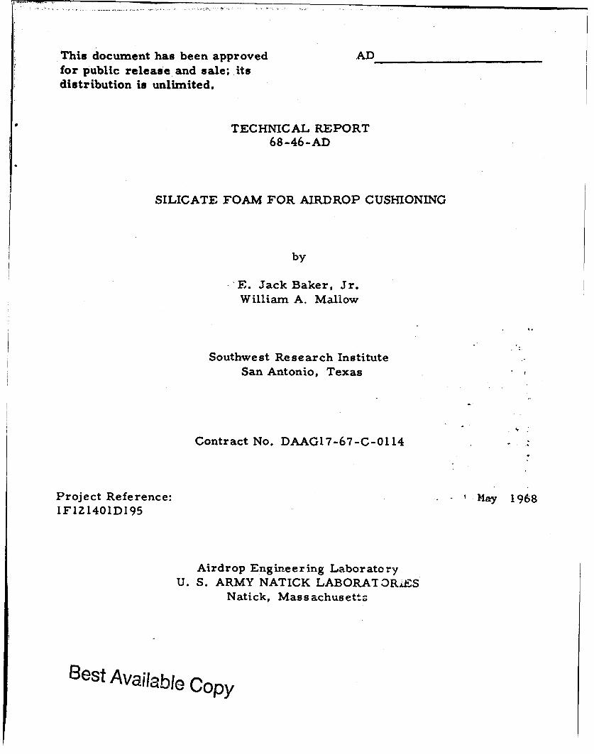
The results of the sodium silicate/perlite tests conducted at NatickLaboratories 25 October 1967 are shown in Figure 1. The data indicated
an initial stress of 45, 000 to 55, 000 psf within the first 10% of the deflection.Then, the unit stress rapidly reduced to approximately 10, 000 psf and thestress increased to 25, 000 to 30,000 psf at about 50% strain.
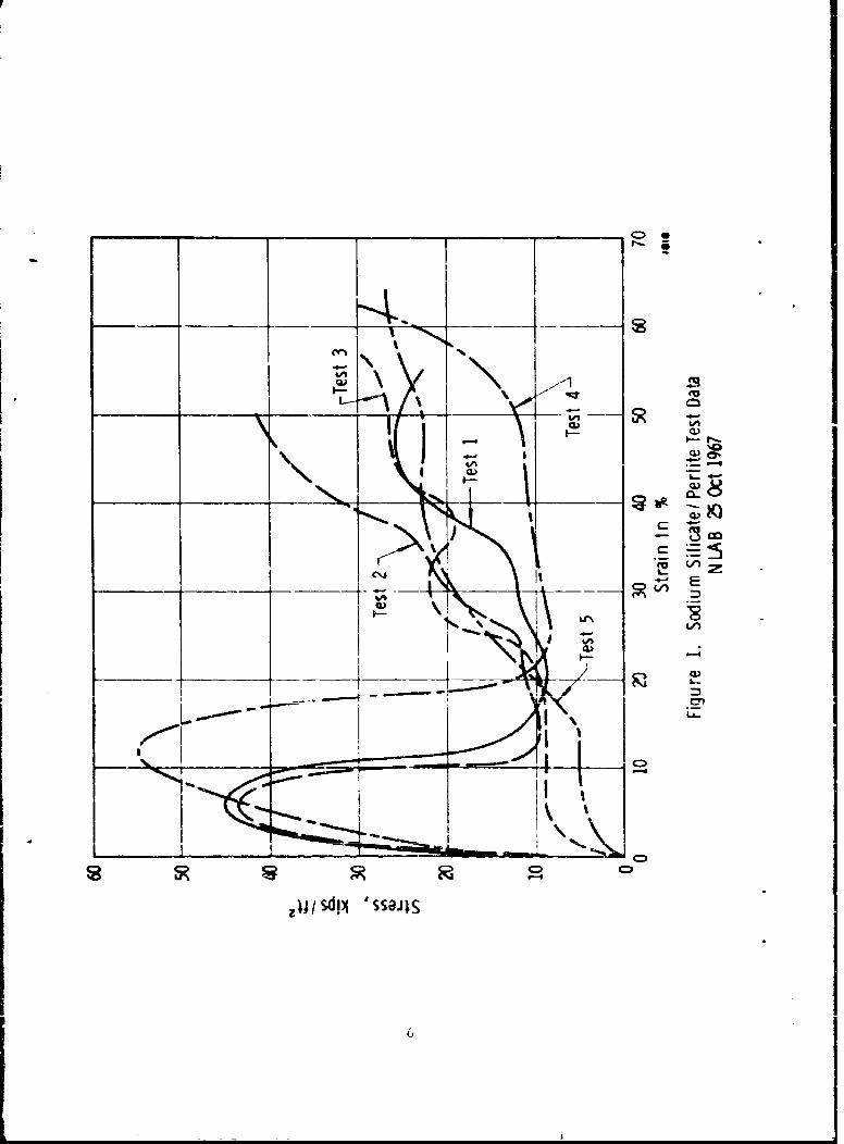
The results of the sodium silicate/vermiculitc also conducted onZ5 October 196"7 are shown in Figure 2. The stress slowly increased toapproximately 20, 000 psf at about 25% deflection. The tabulated resultsfor these tests are shown in Table I on page 8.
These test r-sults indicated that the average unit loading, or stresslevel, was three to four times higher on the average than the desired level."I'hese tests also indicated that the initial onset of failure of the panels was
5
__ __ _ _
I- N)
I N L-
Alm C)
C) C) C)
zjj sdj ssaiis
ICI _ _ _ _ _ _ _ _ _ _ _ _ _U N
r~~~: _ _ _ _ _ _ _ _ _ _ _V _I _ _C_
I I E
j - _ _ _ _ _- 2 1
CD CD
4-grN
Ij/sdil 'ssaJz

TABLE I
RESULTS OF NLAB3S TEST ON 25 OCTOBER 1967
A crageDynamic Panel
Type of Density Impact Crushing ThicknessTest Panel 4lbi'ft 3 ) Velocity (fps) Stress (lb/ftz) (in.
1 Sodium silicate/ 20.19 42.2 21,400 6perlite
z Sodium silicate. 18. 80 4 . 2 25, 4,0perlite
3 Sodium silicatc/ 19. 27 37.6 17,400 6perlite
4 Sodium silicate/ 20.50 30. 6 17,455 3perlicte
5 Sodium silicate/ 20.44 23.6 18, 305 3perlite
6 Sodium silicate/ 19.94 34..4 19, 190 3vermiculite
7 Sodium silicate/ 17.70 2b. 6 21 750 3vermiculite
much higher than debired. In ,ddditi.m to these factb, W• were aware of thefact that the density of the cushion %%aS toe high, and the panels were siightiyfriable.
1o reduce theu high-aet-ragt- stress and densil' and to ,:liminate thehigh-initial stress, it was decided to build the panel with voids. I hese voidswere in the shape of a truncated cone and measured 3 in. at their niajordiameter, Z in. at their n-iiiur di-rnm-tter. cid v. -r- 3 in. in length.
The male section of the mold wkts made of st) rofoam coffee cups.The cups were equally spaced and mounte-d on a plywood board 16 X 18 X3-inches. Several different spacings %%er- evaluated, they were 18, 25,and 30 voids per panel.
The mold was inverted and placed over the plywood form with thestyrooamn cups in place on the board. The mold was then filled with thevarious formulations of sodium silicate and perlite. The bottom of themold was placed in position, and the mold and ply-wood forr.m we.e turnedover. With the plywood form on top, it was easily ;'-.-,oved from the ,riold.Sufficient adhesive power was developed between the pe-'.;t and the sodiumsilicate so that when the cups were removed none of the mixture fell inito

th, void. Ihe top was then placed on the mold, and the mold was placed inthe mnicrowave oven for 20 to 30 min.
Several formulations with different numbers of voids were fabricated.
This was done to study the effect of the voids, and the effect of formulations,on the st ess-strain data. Samples of several of the panels were evaluatedat the Ui.iversity of Texas. Balcones Research Center. Along with the cored
samples, we also evaluated a solid panel of the same formulation as thesodium silicate/perlite samples tested at Natick. Data from the University
of Texas indicated that the initial failure occurred at approximately 4000 psf.
The loading remained constant to approximately 35% strain, and then theunit load slowly increased to about 1Z, 000 psf at 75% strain. This is con-siderably ditferent than the Natick data for the same material. But, this
may be due to the fact that Natick Laboratories tests are conducted in ahorizontal plan~e, aiid the University Of Texab• teats were conducted in a -
vcrtical plane.
As a result of these tests, it was decided to submit eight panels for
the second set of tests at Natick Laboratories on 4 December 1967. Thesepanels had 25 cores as described above and had the following formulation:
Sodium Silicate Solution 5 9 ,7cPerlite 35%
Powdered Polyethylene 6%
lhkT ttrt b.-btrtiji data are plotted in Figure 3. The stress wascunsiderably lower on the second set of tests than on the first set. Infact, thl- stress during the first 30 to 40% strain was so low that approxi-mnatelY 50% of th( kinetic energy wda still available at 50% strain. There-
fore, the stress level increased rapidly between 50% strain and 70% strain.
The tabulated results are snown in Table II on page II.
The results of this second set of dynamic tests indicated that a majorstep had been made in improving the properties of the sodium silicate/perlite panele. Not only was the density of the material reduced by a factor
of almost 2, but the initial high-stress level was not evident and the averagestress was near the desired level.
The first half of the stress-strain levei was lower than desired.
Therefore. a firmer foam panel was fabricated for the third set oi airdropcushions to be evaluated at Natick Laboratories.
"Yhe third formulation consisted of the following items and percentages:
Sodiumn Silicate 6Z.5%Perlite 31 . 3%C.al, ium Carbonate 6. 2%
U - t

opro
1-- Q)C~i L4\
_ _
_CL)
__ __
7.
U-'L
IcA
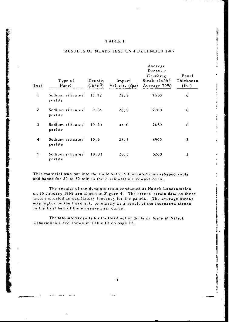
TABLE 11
RESULTS OF NLABS TEST ON 4 DECEMBER 1967
Ave r,-gDyrna~li,
Cruc'hing PanelType of Density Impact Strain (lb/ft2 Thickness
'I est Panel (lb/it 3 ) VelQL2 tY (fps) Average 70%) (in.)
I Sodium silicatc/ 10.72 18.5 7550 6
perlitc
2 Sodium silicate/ 9.85 28. 5 7700 6
pe rlitte
3 Sodium silicate! 10.23 44.0 7650 6perlite
4 Sodium silicate! 10.6 28. 5 4900 3pe rlite
5 Sodium silicate! 10.83 28. 5 5200 3perlite
I This material was put into the muld with 25 truncated cone-shaped voidsand baked for 20 to 30 min in th. 2-kilowatt microu'wav- :ven.
The results of the dynamic tests conducted at Natick Laboratorieson 25 January 1968 are shown in Figure 4. The stress-strain data on thesetests indicated an oscillatory tendency for the pancls. The average stress
was higher on the third set, primarily as a result of the increased stressin the first half of the stress-strain curve.
The tabulated results for the third set of dynamic tes.s at NatickLaboratories are shown in Table Ill on page 13.
ItI111

0A
IQ
Ip I
C1
U-'-
ijj/sdij 'ssajIS

r~ IA131-E III
RESULTS OF NLA13S TES]l ON 25 JANUARY 1968
I, ypC of DtcIibity 1Impa.i. Crusiliig Struss Thiknee5s
I est PdrT)Cl (b/Itf 3) V v I ty~ (( (in.)t
I Sodiuri silikcatc/ 1-'. 4~ 528. 5 10,, Ooperlite
21 Sodium rilicateI 1). 37 Z6. 5 9,050I pr lit c3 Sodium silicate/ 1-2. 25 46. 0 4,200 6I perlite
4 Sodiumn silicate/ 13.tjb5 28. 5 7.,750 3
I ~pe rlite
5 'Sodiuri ili p1"a tc/ 13. 25 28. 5 7815 3
PC L-I1
13

III. Comparison of Sodium Silicate/Perlite System withDesired Characteristics
Eight desired characteristics were outlinedfor an improved energy
dissipater. The following discussion states what each of the desired char-
acteristics are and how well the third sodium silicate/perlite system meets
the desired characteristics.
A. Capable of being stored and shipped in the collapsed state for
economy in storage and shipment; a minimum ratio of I to 15
collapsed to expanded volume is desired.
The third system has a collapsed-to-expanded ratio of
1:2, which is not as good as previously expected, but it is
better than the 1:1 ratio for preexpanded paper honeycomb.
B. Capable of withstanding temperature extremes of -65°F to+125*F in storage and use, and unaffected by direct contact withwate r.
These temperature extremes will not affect the sodiumsilicate/perlite panels. In fact, the uppex .mperaturelimit of the sodium silicate/perlite panel is approximately18000 F. Even though sodium silicate is normally watersoluble, there are several chemicals that make the sodium
silicate completely insoluble in water.
C. Provide an approximately rectangular force-deformationcurve to 80%16 deformation when force is dynamically applied atinitial imp:tct velocities ranging from 20 fps to 90 fps,
The data indicate that the stress-strain curve hardens after
about 60% strain. Up to that point, the curve is basicallyrectangular. Sufficient data have not been taken to determinethe strain-rate sensitivity of the material, but, from thelimited data taken, the sodium silicate/perlite system
appears to be insensitive to strain rate.
D. Average crushing force under condition C above .lhould be6300 psf + 10%.
The average crushing force was slightly above the desiredlevel. But, it has been demonstrated in this program thatthe stress-strain curve can be affected in several ways;therefore, we feel that this goal can be reached.
14

E. Capable of being easily prepared and used in the field witha minimum of auxiliary equipment and personnel.
The sodium silicate/perlite airdrop panels can be easilyprepared in the field with only a few men and several moldsby allowing the panels to air cure at ambient temperatures.If conventional or microwave ovens are available, fewermolds would be required and the cure time shortened.
F. Limit rebound energy, or resilience, to less than 5% of totalenergy dissipated to 80% deformation.
Since the sodium silicate/perltte panels fail by crushingrather than by plastic deformation, the rebound energy isvirtually zero. Under no condition has the rebound energybeen measured as high as 2%.
(3. Limit cost of dissipater material to less than $0. 15/1000 ft-lbof energy dissipated.
Using the average energy dissipated in the third set of dynamictests, the cost of the dissipater material would be $0. 069/1000 ft-lb of energy dissipated. If the desired 6300 ft-lblevel is used for the calculation, $0. 085/1000 ft-lb would bethe cost figure. In either case, the cost of the sodiumsilicate/perlite air cushion compared favorably with thedesired value.
H. The material and supporting supplies shall not possess explo-sive, mechanical, biological, toxicological, or electromagneticradiation effects which could be hazardous from a health or safetystandpoint to using personnel.
The sodium silicate/perlite system does not possess anyproperty listed above that could be hazardous to the healthor safety of personnel using the airdrop cushions.
15
IV. Conclusions and Recommendations
It is concluded that the sodium silicate/perlite system meets orapproaches all goals. This system has several attractive features: theseinclude low cost (as low as $0. 07/1000 ft-lb of energy dissipated), ease ofhandling, nontoxicity, nonflammable characteristic, insensitivity to temper-
ature extremes, has no rebound after impact, and can be used as an airdrop
cushion many times by remolding the materials.
There are some areas that could be improved; these are: to
increase the present l:Z collapsed-to-expanded ratio, extend the maximumstrain level, smooth and flatten the stress-strain curve to a more rectangularcurve, decrease the density and in turn the cost, and reduce the friability.
It is recommended that additional work be carried out to investigatethe use of sodium silicate and sodium silicate/perlite panels for airdrop
cushions. The first step in a new investigation should be to determine thefeasibility of using large microwave units in the field. Since these units
art being considered by the Army for use as kitchen equipment, they mayalso be available for preparation of airdrop cushions. If this provesfeasible, then the foamed panels should be reevaluated.
In the area of sodium silicate/perlite panels, the formulationsshould be modified to reduce the average stress level, flatten the stress-
strain curve, increase the maximum strain level, and reduce the density.
16

APPENDIX
CHEMICAL FORMU LATIONSANLAO
E VALUATIONS
II
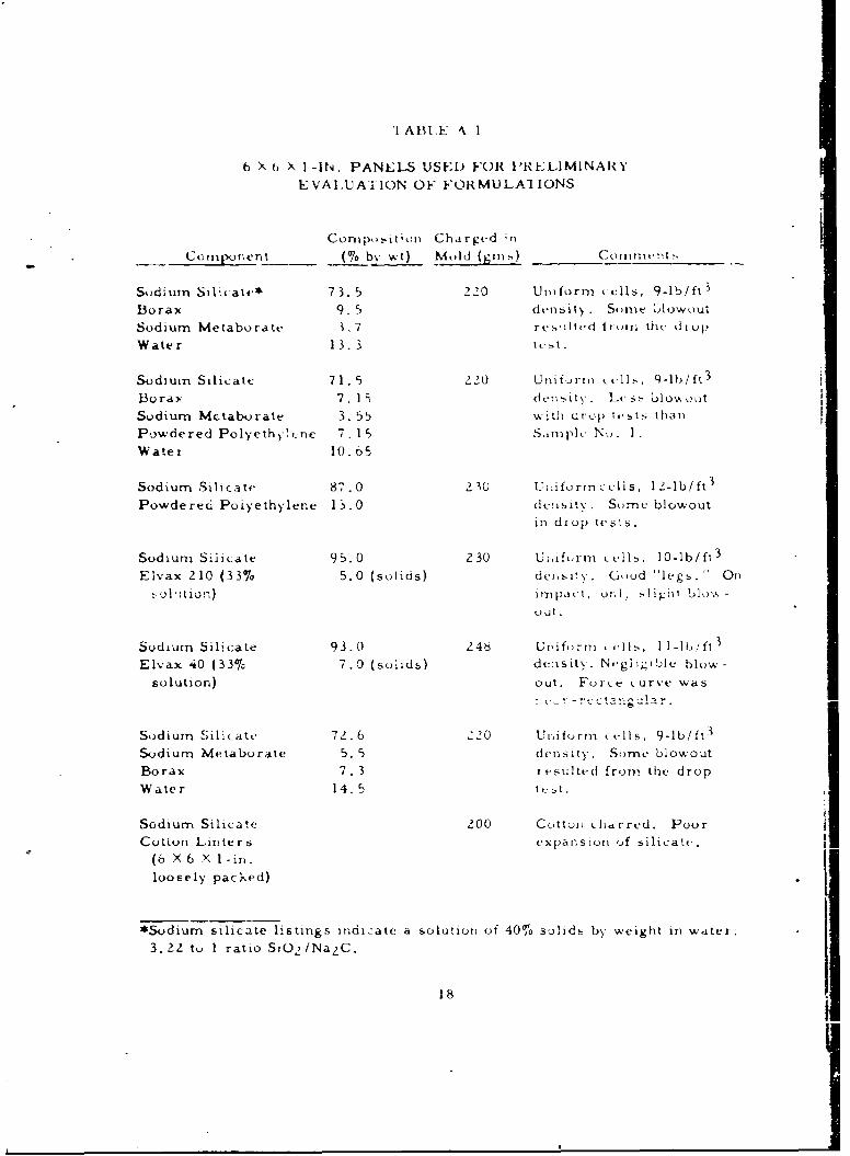
"I ABLY 4. 1
6 X () X I-IN. PANELS USED FOR PRELIMINARYEVALUAIION OF FORMULA} IONS
Composit'on Chargtd *n
- .Ccrnp..nent ({'~% by It) Mold (g9r1) Coin..tt s
Soddium Silcate* 73. 5 220 Uniform (ells, 9-1b/ft
Borax 9. 5 density. Some 1jlow()utSodium Metaborate 1. 7 reollt-d from thl drop
Water 13. 3 tc'.
Sodium Silicate 71. 5 220 Unifurrn Wls, 9-lb/ft 3
Bura: 7. 15 dte11iIy, L Css blox1 out
Sodium Metaborate 3. 55 with drop ltsts than
Powdered Polyeth-t-ne 7. 15 Sin-ple N.,. IWater 10.o5
Sodium Silicate 87.0 2 10 Uj~ifurtn(celis, 12-lb/ft 3
Powdered Poiyethylene 15.0 density. Sume blowout
in drop tests.
Sodium Siýcate 95.0 230 Uiifurm t. vhls. 10-lb/ft 3
Elvax 210 (33% 5.0 (solids) de6s)yU. God "legs." On
o , !1'tioon) imt-n ,c , o.l .li 1 .ht blo', -
out.
Sodium Silicate 93.0 246 U ,iforn mi .llis, 1t-II b.ft3
Elvax 40 (33% 7.0 (solids) density. Ngliaible blow-
solution) out. Force .urve was
!i- -! .-. !, -: an.-.- gu,t -.
Sodium Sili(ate 72.6 220 Unifurm cells, 9-lb/ft 3
Sodium Metaburate 5. 5 density. Some blowoutBorax 7. 3 i t.sulted from the drop
Water 14.5 tt-5t.
Sodium Silicate 200 Cotlon• charrcd. PoorCotton Linters expansion ,of silicate.
(b X 6 X 1-in.
loosely packed)
*Sodium silicate listings indicate a solution of 40% solids by weight in witcr:
3.22 tu I ratio S)O 2 /Na 2 C.
18

TABLE A.1 (Cont'd)
t 6 X 6 X 1 -IN. I'ANELS USED FOR t}RE}UMNARY
EVALUATION OF FORMULATIONS
Composition Chaiged inComponlent (% bý wt) Mold (gins) Comments
Sodium Silicate z00 Poor expansion. GlassFiber Glass (36-in 3 compacted and stratified.
volu.1c loosely
pat.ked into mold)
Sodium Silicate 200 Charred. SuppressedHemp Fiber (36-in 3 foam .
volume)
Sodium Silicate 200 Charred. SuppressedJute Fiber (36-in 3 foam.
volume)
Sodium Silicate 200 Charred. SuppressedExcels'or (36-in 3 foam.
volume)
Sodium Silicate 299 CL-rrcd. SupprcrsscdVinyl Foam (36-in 3 foam.
volume)
Sodium Silicate Z00 Suppressed foam.
Powdered Silica(06-in3 volume)
I Sodium Silicate 200 Unifzrm distribution ofReticular Urethane silicate foam through
Foam (36-in3 vol- urethane matrix. Reducedurne) blowout to minimal.
Urethane partially embrit-tied by local overheating.
Sodium Silicate 66-2/3 240 Uniform dimensions andVermiculite 33-1/3 reproducible. Moderate
blowout on impact.
19
K- -_

TABLE A. I (Co-,'td)
6 X 6 X I -IN. PANELS USED FOR PRELIMINARY
EVALUATION OF FORMULATIONS
Comp.)sition Chargcd in"Component __1% L) v•t) Mtld (grns) Comments
Sodium Silicate 58.0 240 Unifornm dimensions,Perlite 42.0 reprodicible. Moderate
blowout on impact.
Sodium Silicate 62. 5 256 Polyethylene tends toVermiculite 31.25 pyrolize in this mediumPowdered Polyethylene 6.25 upon excessive heating.
Sodium Silicate 55.0 254 Attractive, strong aggre-Perlite 39.5 gate panel. ModeratePowdered Polyethylene 5.5 blowoutout. Elevated corn-
pression strength
(120 psi).
20
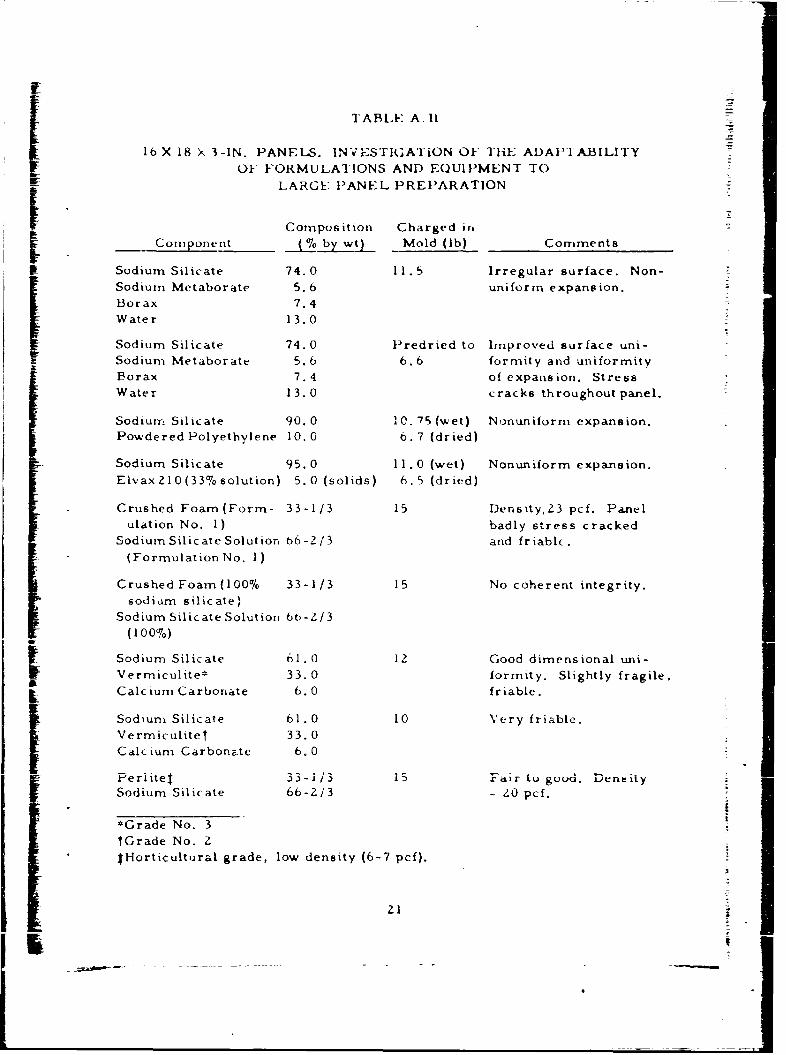
TABLE A. 1l
16 X 18 X 3-IN. PANELS. INVESTIGATiON OF THE ADAP'I ABILITY
OF FORMULATIONS AND EOU11MENT TOIFF LARGE PANEL PREPARATION
Composition Charged irn
Component 6 by wt) Mold (lb) Comments
Sodium Silicate 74.0 11.5 Irregular surface. Non-Sodium Metaborate 5.6 uniform expansion.
Borax 7.4Water 13.0
Sodium Silicate 74.0 Predried to Improved surface uni-Sodium Metaborate 5.6 6.6 formity and uniformityIBorax 7.4 of expansion. StressWater 13.0 cracks throughout panel.
Sodium Silicate 90.0 10.75 (wet) Nonuniform expansion.Powdered Polyethylene 10.0 6.7 (dried)
Sodium Silicate 95.0 11 . 0 (wet) Nonuniform expansion.Elvax210(33,% solution) 5.0 (solids) 6.5 (dried)
Crushed Foam(Form- 33-1/3 15 Dersity,Z3 pcf. Panelulation No. 1) badly stress cracked
Sodium Silicate Solution 66-2/3 and friable.(Formulation No. 1)
Crushed Foam(100% 33-1/3 15 No coherent integrity.
sodium silicate)Sodium Silicate Solution 6b-2/3
(100%)
Sodium Silicate 61.0 12 Good dimensional uni-
Vermiculite* 33.0 formity. Slightly fragile,Calcdium Carboate 6.0 friable.
Sodium Silicate 61.0 10 Very friable.
Vermiculitel 33.0
Calcium Carbona~te 6.0
Periitel 33-1 /3 iS Fair tu guoad. De~neltySodium Silicate 66-2/3 - 0 pcf. -
*Grade No. 3lGrade No. ZtHorticultural grade, low density (6-7 pcf).
21-:
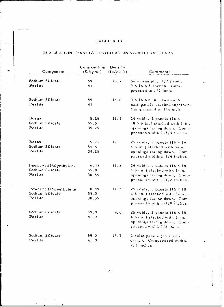
"IABLE A. ll1
16 X 18 X 3-IN. PANELS TESTED AT UNIVERSITY OF '1E\-XA>
Composition Density
Component (% by wt) (lb/cu ft) Comrmnents
Sodium Silicate 59 10.7 Solid sample. 1/2 panel,Perlite 41 0 X lb X 3-inches. Com-
pressed to 1/2 inch.
Sodium Silicate 59 18.6 9 X lt X b in. , twxo eachPerlite 41 half-panels stacked together.
Cuinpresbud to 3'4 inch.
Borax Z.25 11.5 25 voids, Z panels (1 xSodium Silicate 55.5 18 X 6-in. ) stacked with 3-in.Perlite 39.-5 openings facing down. Com-
pressed width 1-3/4 inches.
Borax 5.5 12 25 voids, 2 panels (16 X 18Sodium Silicate 55.5 \ 6-in. ) stacked with 3-in.Perlite 39.25 openings facing down. Com-
pressed width,2-1/4 inches.
Powd&rcd Polyethylnt.e o.44 11.8 25 voids, - panels (16 '- 18Sodium Silicate 55.0 K 6 -in. ) stacked with 3-in.Perlite 38. 55 openings facing down. Corn-
pressed \% idt! "-1 /2 inches.
Powdcrcd Polyethylrce b. 45 11. 25 voids, ' panels (10 X 18Sodium Silicate 55.0 X b-in. ) stacked with 3-in.Perlite 38.55 openings facing down. Com-
pressed width '-1 /8 inches.
Sodium Silicate 59.0 9.6 25 voids, 2 panels (16 X 18Perlite 41.0 X b-in. ) stacked with 3-in.
openinvs facing down. Corn-
F .GSý ` -; 1 , "• t, 6 •1fCIý
Sodium Silicate 59.0 13.7 2 solid panels (16 x 16 'xPerlite 41.0 u-in. ). Compressed width,
2.3 inche s.
IT

TABLE A 111 (Cont'd)
-I >, 18 X 3-IN. IPANELS TESTED AT UNIVERSITY 01" TEXAS
4
Composition DensityComl ponent (G by wt) (Ib/cu ft) Comments
Sodium Silic-ate 59.0 10. 5 25 voids, 2 panels (16 X 18
Perlite 41.0 X 6-in.) stacked with 3-in.
openings center-faced.
Compressed width
1.(4 inches.
Sodiun. Silicate 53.0 12.2 25 voids, 2 pa-nels (16 X 18
Perlite 37.6 X b-in. ) stacked with 3-in.Powdered Polyethylene 9.4 openings center-faced.
Compressed width1 2.6 inches.
Sodium Silicate 51. 12.0 Z5 voids, Z panels (16 X 18
Perlite 36.3 X 6-in. ) stacked with 3-in.Powdered Polyethylene 12. z openings center-faced.
Compressed widthZ.6 inches. Friable.IL
Sodium Siicate 55.0 9.4 30 voids, 2 panels (16 X 18Perlite 39 X 6-in. ) stacked with 3-in.Powdered Polyethylene 6 openings center-faced.
Compressed widthS1.4 inches.
Sodium Silicate 53.0 IU 30 voids, 2 panels sandwichedPerlite 38 (16 X 18 X 6-in. ) with 3 -in.Powdered Polyethylene 9 Openings center-faced.
Compresscd width2. 1 inches.
Sodium Silicate 59 13.7 Screened low density.Perlite 41 Perlite for formulation. S
Z3I __ __

TABLE A. IV
16 X 18 X 3-IN. PANELS TESTED AT' U.S. ARMYNATICK LAB3ORATORIES
Composition DensityComponent (% by wt ) (lh/t u ft) Comriients
Sodium Silicate 59 18-20 8 sanipleb tested at U.S.Perlite 41 Army Natick Laboratories,
'5 October 1967.
Sodium Silicate 64 18-20 2 samples tested at U.S.Vermiculite 36 Army Natick Laboratories,
25 October 1967.
Sodium Silicate 59 11 Prepared 8 each and deliveredPerlite 34.8 to U.S. Army Natick Labora-Powdered Polyethylene 6.8 tories facility. 25 hole pa-nels
(10 X 17 X 3-in. ) each,
4 December 1967.
Sodium Silicate 6Z.5 IZ-13 Prepared 8 panels for ship-Perlite 31.25 ment to U.S. Army NatickCalcium Carbinate 6.25 Laboratories facility on
ZZ December 1967. Z5holes,evaluated on 25 January 1968.
24
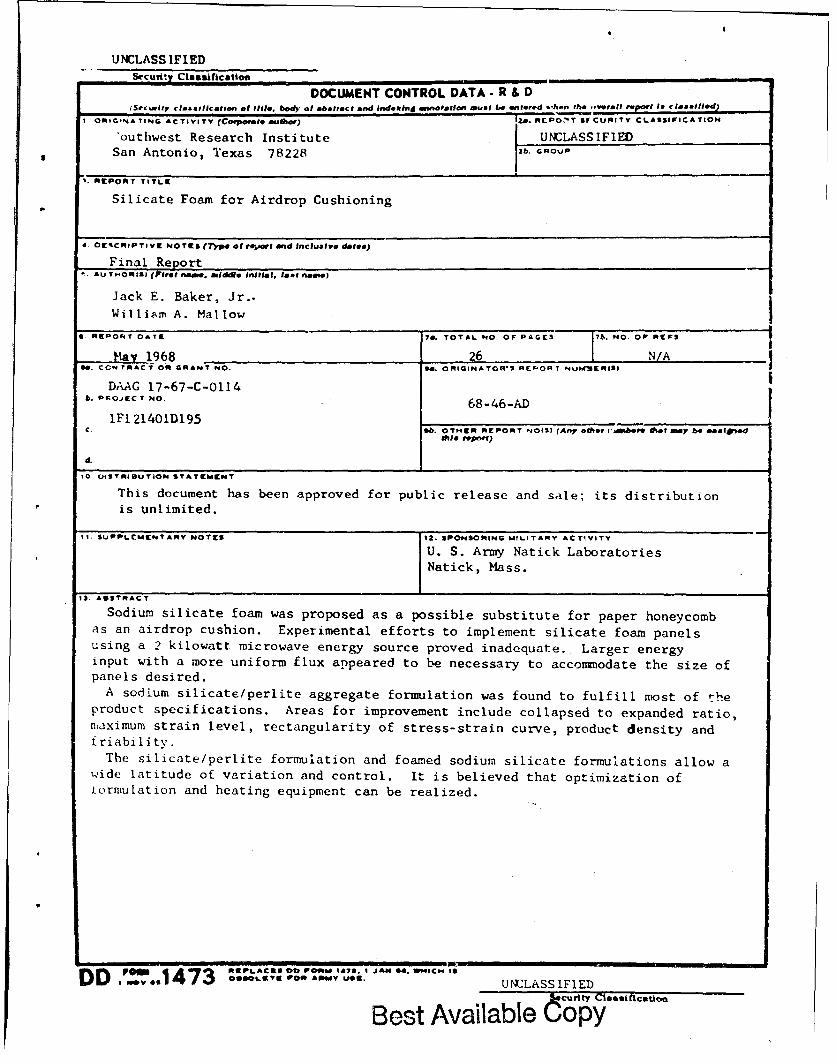
UNCLASS IFIEDSecurity Classification
DOCUMENT CONTROL DATA - R & D(Security claaImlication of till, bod, of abstract and Indexing i•nnotation ,1um$ be entlerd %,hen the ,v9rwjj rvport! Is ctamtl led)
ORIGINATING ACTIVITY (C•oporate author) 2dA. CLPO:T SU CURITY CLASSIFICATION
"outhwest Research Institute UNCLASSIFIEDSan Antonio, Texas 78228 2b. GROuP
'. ftPORT TITLE
Silicate Foam for Airdrop Cushioning
4. O'tSCRIPTIVr NOT9I (27)pe at reort and Inclusive dles)
Final ReportAU TMORIS) (Fritet name. middle initial, a•otl name)
Jack E. Baker, Jr..Williamr A. Mallow
1 R 96PO84T 7as. TOTAL NO. OF PAGES •7. NO. OPr neS
May 1968 26 -N/Aa. CCNT RACT Oft GRANT NO. 94. ORIGINATOR'%S REOR T NUIWSXiSI
DAAG 17-67-C-0114h. PKOjECT NO. 68-46-AD
IFI.21401D195C. 6b. OTHER REPORT NOIS) (Any otier v'•.bore Shat maoy be asaatgnd
trle Ioporf)
d.
10. DISTRIBUTION STATEMENT
This document has been approved for public release and sale; its distributionis unlimited.
I1. StJPPLtUMENTARY NOTE$ 12. SPONSORING MILITARY ACTIVITY
U. S. Army Natick LaboratoriesNatick, Mass.
IS. ABSTRACT
Sodium silicate foam was proposed as a possible substitute for paper honeycombas an airdrop cushion. Experimental efforts to implement silicate foam panelsusing a 2 kilowatt microwave energy source proved inadequate. Larger energyinput with a more uniform flux appeared to be necessary to accommodate the size ofpanels desired.
A sodium silicate/perlite aggregate formulation was found to fulfill most of theproduct specifications. Areas for improvement include collapsed to expanded ratio,maximum strain level, rectangularity of stress-strain curve, product density andfriability.
The silicate/perlite formulation and foamed sodium silicate formulations allow awide latitude of variation and control. It is believed that optimization ofiormulation and heating equipment can be realized.
row 0EPLAC&S0 Cob P00511473. I JA34 0. WBICNq IS, DO3v,,, _20LsTK P000 ANV uSE. UNCLASSIFIED
Best Available COPlCY"''"

UNEASSIFIEDSecurity cleueinct= ________________
14, LINK A LINK a LINK CKItY WORDS -I
ftOt. Wi ROt.g WT RO")L E WT
Impact strength 8Energy 8 9Absorption 8 8Dissipation 8 8Impact shock 1Sodium silicate 10 10 9Foams 10 10 9Perlite I10 10 9Vermiculite 10 10 9Airdrop operations 4 4 4Stress-strain measurements 8
UNCLA.SSIFIEDSecurity ClassIieiatlon
Best Available Copy