CIM for Dynamicscimug.ucaiug.org/Meetings/eu2018/2018 Ljubljana... · Turbine Governor:ExcIEEEAC1A...
17
© 2017 Electric Power Research Institute, Inc. All rights reserved. Pat Brown EPRI CIM U Track II June 5, 2018 CIM for Dynamics
Transcript of CIM for Dynamicscimug.ucaiug.org/Meetings/eu2018/2018 Ljubljana... · Turbine Governor:ExcIEEEAC1A...
© 2017 Electric Power Research Institute, Inc. All rights reserved.
Pat Brown
EPRI
CIM U Track II
June 5, 2018
CIM for Dynamics
2© 2017 Electric Power Research Institute, Inc. All rights reserved.
CIM for Dynamics
▪Topics
– Introduction to Dynamics
– Dynamics in the CIM
– Status update

3© 2017 Electric Power Research Institute, Inc. All rights reserved.
CIM for Dynamics
Introduction
▪Dynamics simulates transient (sub-cycle) behavior of the grid
▪Required data includes:
– Individual dynamic behavior of each piece of equipment
– Connectivity and steady state electrical characteristics (EQ)
– Starting point steady state solution (TP, SV)
▪Dynamics models are shared
– Among transient analysis applications
– Among TSOs and ISOs
▪Background
– Creation of standard behavior models started in mid-1960s
– 100+ standard behavior models from IEEE and IEC
– Multiple defacto standard models
4© 2017 Electric Power Research Institute, Inc. All rights reserved.
CIM for Dynamics
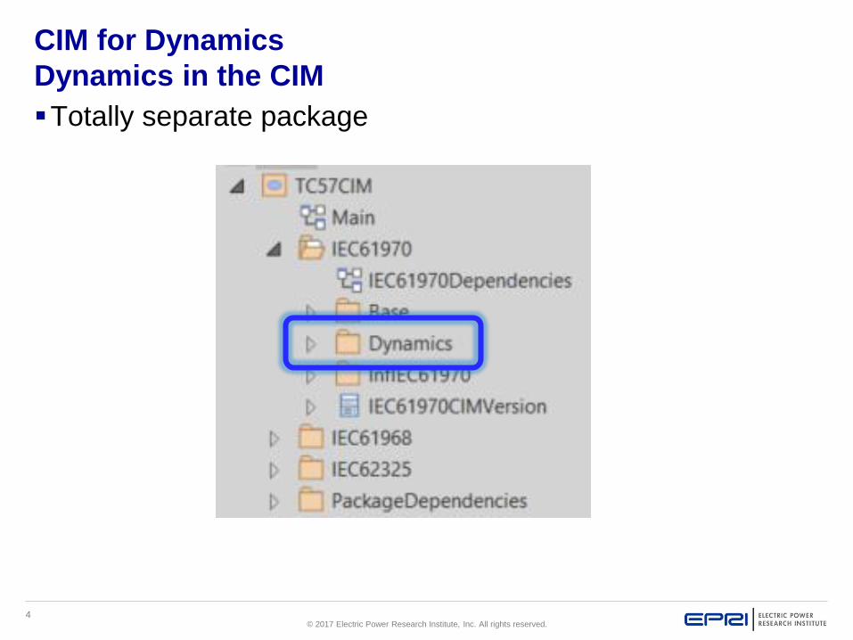
Dynamics in the CIM
▪Totally separate package

5© 2017 Electric Power Research Institute, Inc. All rights reserved.
Dynamics
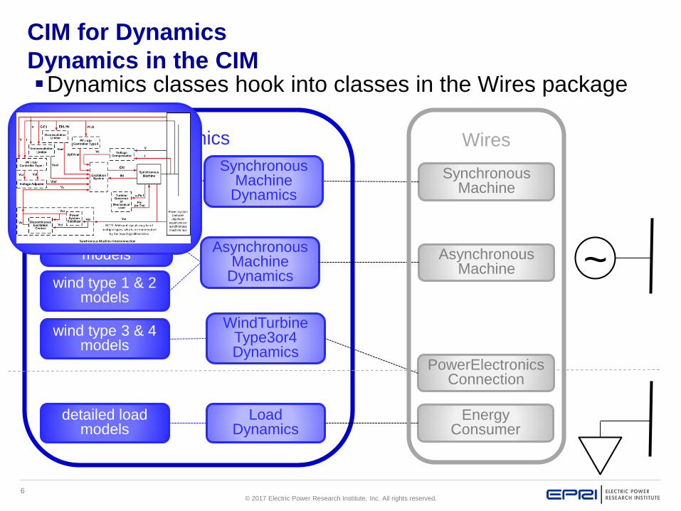
CIM for Dynamics
Dynamics in the CIM▪Dynamics classes hook into classes in the Wires package
~
SynchronousMachine
AsynchronousMachine
EnergyConsumer
AsynchronousMachine
Dynamics
LoadDynamics
wind type 1 & 2 models
detailed load models
Wires
PowerElectronics Connection
SynchronousMachine
Dynamics
detailed component
models
mechanical load & governor
models
wind type 3 & 4 models
WindTurbineType3or4Dynamics
6© 2017 Electric Power Research Institute, Inc. All rights reserved.
Dynamics
detailed component
models
CIM for Dynamics
Dynamics in the CIM▪Dynamics classes hook into classes in the Wires package
~
SynchronousMachine
AsynchronousMachine
EnergyConsumer
AsynchronousMachine
Dynamics
LoadDynamics
wind type 1 & 2 models
detailed load models
PowerElectronics Connection
SynchronousMachine
Dynamics
mechanical load & governor
models
wind type 3 & 4 models
WindTurbineType3or4Dynamics
detailed component models
Wires

7© 2017 Electric Power Research Institute, Inc. All rights reserved.
CIM for Dynamics
Dynamics in the CIM▪Synchronous machine dynamic models are comprised of:
– dynamic function block diagrams
– combined in
standard
interconnection
patterns by
output/input
signals

8© 2017 Electric Power Research Institute, Inc. All rights reserved.
CIM for Dynamics
Dynamics in the CIM▪Dynamics classes hook into classes in the Wires package
SynchronousMachine
SynchronousMachine
Dynamics
detailed component
models

9© 2017 Electric Power Research Institute, Inc. All rights reserved.
CIM for Dynamics
Dynamics in the CIM▪Synchronous machine dynamic models are comprised of:
– dynamic function block diagrams
– combined in
standard
interconnection
patterns by
output/input
signals

10© 2017 Electric Power Research Institute, Inc. All rights reserved.
CIM for Dynamics
Dynamics in the CIM▪Function block diagrams – represent ‘chunk’ of self-
contained dynamic behavior
– Many standard models of a given type– Behavior described by function blocks with parameters
Excitation System model ExcLIN1

11© 2017 Electric Power Research Institute, Inc. All rights reserved.
CIM for Dynamics
Dynamics in the CIM▪Parameter values are class attributes

12© 2017 Electric Power Research Institute, Inc. All rights reserved.
▪Simple generator
model using
standard dynamics
models
CIM for Dynamics
Dynamics in the CIM
object ExampleStandar dModel
static power system model
dynamics model
Excitation System
Synchronous Machine
Turbine Governor
:ExcIEEEAC1A
enabled = true
tb = 0.0
tc = 0.0
ka = 0.02
ta = 0.02
vamax = 14.5
vamin = -14.5
te = 0.8
kf = 0.03
tf = 1.0
kc = 0.2
kd = 0.38
ke = 1.0
ve1 = 4.18
seve1 = 0.1
ve2 = 3.14
seve2 = 0.03
vrmax = 6.03
vrmin = -5.43
:Sy nchr onousMachine
:Sy nchr onousMachineTimeConstantReactance
enabled = true
damping = 0.0
inertia = 3.0
saturationFactor = 0.02
saturationFactor120 = 0.12
statorLeakageReactance = 0.15
statorResistance = 0.005
efdBaseRatio = 1.0
ifdBaseType = ifag
ifdBaseValue = 0.0
rotorType = roundRotor
modelType = subtransient
xDirectSync = 1.8
xDirectTrans = 0.5
xDirectSubtrans = 0.2
xQuadSync = 1.6
xQuadTrans = 0.3
tpdo = 5.0
tppdo = 0.03
tpqo = 0.5
tppqo = 0.03
Standard model
:Gov SteamIEEE1
mwbase = 647.0
k = 20.0
t1 = 0.15
t2 = 0.67
t3 = 0.15
uo = 0.5
uc = -0.4
pmax = 1.0
pmin = 0.0
t4 = 0.25
k1 = 0.284
k2 = 0.0
t5 = 10.0
k3 = 0.294
k4 = 0.0
t6 = 0.5
k5 = 0.472
k6 = 0.0
t7 = 0.0
k7 = 0.0
k8 = 0.0

13© 2017 Electric Power Research Institute, Inc. All rights reserved.
▪Simple generator
model using
proprietary model
for turbine-governor
CIM for Dynamics
Dynamics in the CIM
object ExampleFunct ionBlockP r opr ieta r y Model
static power system model
dynamics model
Excitation System
Synchronous Machine
Turbine Governor
:P r opr ieta r y Pa r ameter Dy namics
parameterNumber = 3
floatParameterValue = 0.15
:P r opr ieta r y Pa r ameter Dy namics
parameterNumber = 2
floatParameterValue = 0.0
:P r opr ieta r y Pa r ameter Dy namics
parameterNumber = 1
booleanParameterValue = false
:Tur bineGov er nor User Def ined
name = GovProprietaryFred
enabled = true
proprietary = true
:ExcIEEEAC1A
enabled = true
tb = 0.0
tc = 0.0
ka = 0.02
ta = 0.02
vamax = 14.5
vamin = -14.5
te = 0.8
kf = 0.03
tf = 1.0
kc = 0.2
kd = 0.38
ke = 1.0
ve1 = 4.18
seve1 = 0.1
ve2 = 3.14
seve2 = 0.03
vrmax = 6.03
vrmin = -5.43
:Sy nchr onousMachine
:Sy nchr onousMachineTimeConstantReactance
enabled = true
damping = 0.0
inertia = 3.0
saturationFactor = 0.02
saturationFactor120 = 0.12
statorLeakageReactance = 0.15
statorResistance = 0.005
efdBaseRatio = 1.0
ifdBaseType = ifag
ifdBaseValue = 0.0
rotorType = roundRotor
modelType = subtransient
xDirectSync = 1.8
xDirectTrans = 0.5
xDirectSubtrans = 0.2
xQuadSync = 1.6
xQuadTrans = 0.3
tpdo = 5.0
tppdo = 0.03
tpqo = 0.5
tppqo = 0.03
:P r opr ieta r y Pa r ameter Dy namics
parameterNumber = 4
floatParameterValue = 3.2
Proprietary
user-defined
model
Standard model

14© 2017 Electric Power Research Institute, Inc. All rights reserved.
CIM for Dynamics – Status Update
▪ IEC standards – Edition 1
– 61970-302 (canonical) - International Standard as of April 12, 2018
– 61970-457 (profile) – CD (Committee Draft) in next few months
▪Edition 2– HVDC, static VAR compensators, shunt compensators, relays, FACTS,
composite load…
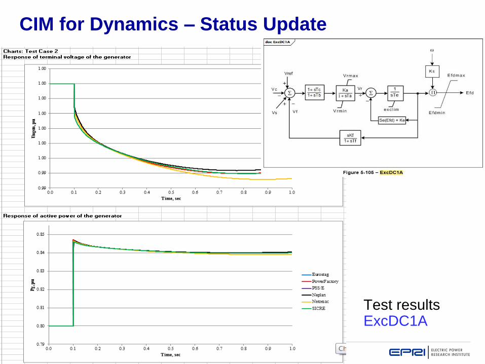
▪ENTSO-E Interoperability testing– Weekly ongoing calls– Participants
▪ Eurostag▪ DigSILENT (PowerFactory)▪ Siemens PTI (PSSE)▪ Neplan▪ Netomac▪ SICRE
– Testing data exchange and interpretation of standard dynamic models
15© 2017 Electric Power Research Institute, Inc. All rights reserved.
CIM for Dynamics – Status Update
▪Status
– 150+ standard models identified, documented and entered into UML
– Preliminary inclusion of Wind models - collaboration with IEC TC88
WG27 who are developing dynamic models
– UML-driven documentation strategy utilized
– In CIM16
– NWIP and CD being drafted by WG13
– Use planned by ENTSO-E and ERCOT
Test results ExcDC1A

16© 2017 Electric Power Research Institute, Inc. All rights reserved.
CIM for Dynamics
▪Questions?
▪For more information, contact
– Pat Brown [email protected]
– Chuck DuBose [email protected]
– Dr. Chavdar Ivanov [email protected]
17© 2017 Electric Power Research Institute, Inc. All rights reserved.
Together…Shaping the Future of Electricity


![0.00 0.02 0.04 0.06 0.08 0.10 0.12 0.14 0.16 [A] (M)ekwan/pdfs/29 - Applications...0.00 0.02 0.04 0.06 0.08 0.10 0.12 0.14 0.16 0.0 5.0x10⁻⁷ 1.0x10⁻⁶ 1.5x10⁻⁶ 2.0x10⁻⁶ 2.5x10⁻⁶ s-1)](https://static.fdocuments.net/doc/165x107/5aad3f997f8b9a2e088df1bd/000-002-004-006-008-010-012-014-016-a-m-ekwanpdfs29-applications000.jpg)