CIBOLA MUTUAL WATER COMPANY - …€¦ · 432313 OVERHUNG CLOSE-COUPLED HORIZONTAL CENTRIFUGAL...
64
Technical Specifications
Transcript of CIBOLA MUTUAL WATER COMPANY - …€¦ · 432313 OVERHUNG CLOSE-COUPLED HORIZONTAL CENTRIFUGAL...

Technical
Specifications

March 23, 2018
WINTERHAVEN WATER/SEWER IMPROVEMENT
Winterhaven, California 92283
Winterhaven Water District 494 2nd Avenue
Winterhaven, California 92283

TABLE OF CONTENTS
DIVISION 01 – GENERAL REQUIREMENTS
011000 SUMMARY 014000 QUALITY REQUIREMENTS DIVISION 03 – CONCRETE
033000 CAST-IN-PLACE CONCRETE
DIVISION 09 – FINISHES
099000 PAINTING AND COATING
DIVISION 22 – PLUMBING
220553 INDENTIFICATION FOR PLUMBING PIPING AND EQUIPMENT
DIVISION 26 – ELECTRICAL
260503 EQUIPMENT WIRING CONNECTIONS
DIVISION 33 – UTILITIES
330130 SEWER AND MANHOLE TESTING 330513 MANHOLES AND STRUCTURES 330519 PRESSURE PIPING TIED JOINT RESTRAINT SYSTEM 330526 UTILITY IDENTIFICATION 331113 PUBLIC WATER UTILITY DISTRIBUTION PIPING 331216 WATER UTILITY DISTRIBUTION VALVES 331300 DISINFECTING OF WATER UTILITY DISTRIBUTION DIVISION 40 – PROCESS INTERCONNECTIONS
400565 SWING CHECK VALVES 407113 MAGNETIC FLOW METERS 407326 GAUGE-PRESSURE TRANSMITTERS 432313 OVERHUNG CLOSE-COUPLED HORIZONTAL CENTRIFUGAL PUMPS 434221 WELDED STEEL PRESUURE TANKS MISCELLANEOUS HORIZON PTF-60 VENTILATION SYSTEM

Copyright 2011 ARCOM SpecText, Short Form 11/2011
SUMMARY 011000 - 1
SECTION 011000 - SUMMARY
PART 1 - GENERAL
1.1 SUMMARY
A. Section Includes:
1. Contract description. 2. Owner-Furnished Products 3. Work sequence.
1.2 CONTRACT DESCRIPTION
A. Work for this Project includes improvements to the Water Treatment Plant and Sewer Disposal System in Winterhaven California. More Specifically, work will include the removal of the following items: three 20 HP pump station pumps, 8” header piping, 6” steel pipe and appurtenances, concrete asbestos pipe between pump station and hydropneumatic tank, 300 amp SES panel, electrical panel and compressor unit for hydro pneumatic tank, 10,000 gallon hydro pneumatic tank, hydro pneumatic tank saddles, well pump and motor from well #2, existing electrical panel from well #2, existing chain link fence, two sewer manholes and existing sewer lift station electrical panel and the installation of the following items: three new 20 HP motors with pumps, new cement mortar lined flanged ductile iron pipe and fittings with fusion bonded epoxy, new class 200 PVC water pipe, new 400 amp SES panel, new auto dialer for water system, new 8” micrometer ultra mag totalizing flow meter, new 10,000 gallon hydro pneumatic tank with electrical panel and oiless charging system, new hydropneumatic tank bypass piping using 8” class 200 PVC with cement mortar lined flanged ductile iron fittings with fusion bonded epoxy, new 8” ductile iron resilient wedge gate valves with fusion bonded epoxy inside and out, new 15 HP 7” 400 GPM submersible pump with new electrical cabinet, new Horizon PTF-60 ventilation system, new chain link fence with gate, two new sewer manholes and a new sewer lift station electrical panel with auto dialer.
B. Perform Work under fixed cost Contract with Owner according to Conditions of Contract.
1.3 WORK SEQUENCE
A. Sequencing of Construction Plan: Before start of construction, submit three copies of construction plan regarding phasing of demolition and new Work for acceptance by Owner. The plan shall include by-pass pumping details and sequence of construction as well as electrical phasing to ensure the booster station is operational throughout construction. After acceptance of plan, construction sequencing shall comply with accepted plan unless deviations are accepted by Owner in writing.

Copyright 2011 ARCOM SpecText, Short Form 11/2011
QUALITY REQUIREMENTS 014000 - 1
SECTION 014000 - QUALITY REQUIREMENTS
PART 1 - GENERAL
1.1 SECTION INCLUDES
A. Quality control.
B. Tolerances.
C. References.
D. Labeling.
E. Mockup requirements.
F. Testing and inspection services.
1.2 QUALITY CONTROL
A. Monitor quality control over suppliers, manufacturers, products, services, site conditions, and workmanship, to produce Work of specified quality.
B. Comply with specified standards as the minimum quality for the Work except where more stringent tolerances, codes, or specified requirements indicate higher standards or more precise workmanship.
C. Perform Work using persons qualified to produce required and specified quality.
D. Supervise performance of Work in such manner and by such means to ensure that Work, whether completed or in progress, will not be subjected to harmful, dangerous, damaging, or otherwise deleterious exposure during construction period.
1.3 TOLERANCES
A. Monitor fabrication and installation tolerance control of products to produce acceptable Work. Do not permit tolerances to accumulate.
B. Comply with manufacturers' recommended tolerances and tolerance requirements in reference standards. When such tolerances conflict with Contract Documents, request clarification from Engineer before proceeding.

Copyright 2011 ARCOM SpecText, Short Form 11/2011
QUALITY REQUIREMENTS 014000 - 2
1.4 REFERENCES
A. For products or workmanship specified by association, trade, or other consensus standards, comply with requirements of standard except when more rigid requirements are specified or are required by applicable codes.
B. When requirements of indicated reference standards conflict with Contract Documents, request clarification from Engineer before proceeding.
C. Neither contractual relationships, duties, or responsibilities of parties in Contract nor those of Engineer shall be altered from Contract Documents by mention or inference in reference documents.
1.5 LABELING
A. Attach label from agency approved by authorities having jurisdiction for products, assemblies, and systems required to be labeled.
B. Label Information: Include manufacturer's or fabricator's identification, approved agency identification, and the following information, as applicable, on each label:
1. Model number. 2. Serial number. 3. Performance characteristics.
1.6 MOCK-UP REQUIREMENTS
A. Tests will be performed under provisions identified in this Section and identified in individual product Specification Sections.
B. Assemble and erect specified or indicated items with specified or indicated attachment and anchorage devices, flashings, seals, and finishes.
C. Accepted mockups shall be comparison standard for remaining Work.
1.7 TESTING AND INSPECTION SERVICES
A. Employ and pay for services of an independent testing agency or laboratory acceptable to Owner to perform specified testing.
1. Before starting Work, submit testing laboratory name, address, and telephone number, and names of full-time Professional Engineer and responsible officer.
2. Submit copy of report of laboratory facilities' inspection made by Materials Reference Laboratory of National Bureau of Standards during most recent inspection, with memorandum of remedies of deficiencies reported by inspection.
B. Independent firm will perform tests, inspections, and other services specified in individual Specification Sections and as required by Engineer.

Copyright 2011 ARCOM SpecText, Short Form 11/2011
QUALITY REQUIREMENTS 014000 - 3
1. Laboratory: Authorized to operate in State of California.
C. Reports shall be submitted by independent firm to Engineer, Contractor, and authorities having jurisdiction, indicating observations and results of tests and compliance or noncompliance with Contract Documents.
D. Cooperate with independent firm; furnish samples of materials, design mix, equipment, tools, storage, safe access, and assistance by incidental labor as requested.
1. Notify Engineer and independent firm 24 hours before expected time for operations requiring services.
2. Make arrangements with independent firm and pay for additional Samples and tests required for Contractor's use.
E. Employment of testing agency or laboratory shall not relieve Contractor of obligation to perform Work according to requirements of Contract Documents.
F. Retesting or re-inspection required because of nonconformance with specified or indicated requirements shall be performed by same independent firm on instructions from Engineer. Payment for retesting or re-inspection will be charged to Contractor by deducting testing charges from Contract Sum/Price.
G. Agency Responsibilities:
1. Test Samples of mixes submitted by Contractor. 2. Provide qualified personnel at Site. Cooperate with Engineer and Contractor in
performance of services. 3. Perform indicated sampling and testing of products according to specified standards. 4. Ascertain compliance of materials and mixes with requirements of Contract Documents. 5. Promptly notify Architect/Engineer and Contractor of observed irregularities or
nonconformance of Work or products. 6. Perform additional tests required by Architect/Engineer. 7. Attend preconstruction meetings and progress meetings.
H. Agency Reports: After each test, promptly submit one copy of report to Engineer, Contractor, and authorities having jurisdiction. When requested by Engineer, provide interpretation of test results.
I. Limits on Testing Authority:
1. Agency or laboratory may not release, revoke, alter, or enlarge on requirements of Contract Documents.
2. Agency or laboratory may not approve or accept any portion of the Work. 3. Agency or laboratory may not assume duties of Contractor. 4. Agency or laboratory has no authority to stop the Work.

Copyright 2011 ARCOM SpecText, Short Form 11/2011
QUALITY REQUIREMENTS 014000 - 4
PART 2 - PRODUCTS - Not Used
PART 3 - EXECUTION - Not Used
END OF SECTION 014000

Copyright 2011 AIA MasterSpec Short Form 02/11
CAST-IN-PLACE CONCRETE 033000 - 1
SECTION 033000 - CAST-IN-PLACE CONCRETE
PART 1 - GENERAL
1.1 SUMMARY
A. Section includes cast-in-place concrete, including formwork, reinforcement, concrete materials, mixture design, placement procedures, and finishes.
1.2 ACTION SUBMITTALS
1.3 QUALITY ASSURANCE
A. Manufacturer Qualifications: A firm experienced in manufacturing ready-mixed concrete products and that complies with ASTM C 94/C 94M requirements for production facilities and equipment.
1. Manufacturer certified per NRMCA's "Certification of Ready Mixed Concrete Production Facilities."
B. Testing Agency Qualifications: An independent agency, qualified per ASTM C 1077 and ASTM E 329 for testing indicated.
C. Welding Qualifications: Qualify procedures and personnel per AWS D1.4/D 1.4M, "Structural Welding Code - Reinforcing Steel."
D. ACI Publications: Comply with the following unless modified by requirements in the Contract Documents:
1. ACI 301, "Specifications for Structural Concrete," 2. ACI 117, "Specifications for Tolerances for Concrete Construction and Materials."
E. Concrete Testing Service: Engage a qualified independent testing agency to perform material evaluation tests and to design concrete mixtures.
PART 2 - PRODUCTS
2.1 FORM-FACING MATERIALS
A. Rough-Formed Finished Concrete: Plywood, lumber, metal, or another approved material. Provide lumber dressed on at least two edges and one side for tight fit.

Copyright 2011 AIA MasterSpec Short Form 02/11
CAST-IN-PLACE CONCRETE 033000 - 2
2.2 STEEL REINFORCEMENT
A. Reinforcing Bars: ASTM A 615/A 615M, Grade 60 (Grade 420), deformed.
B. Bar Supports: Bolsters, chairs, spacers, and other devices for spacing, supporting, and fastening reinforcing bars and welded wire reinforcement in place. Manufacture bar supports from steel wire, plastic, or precast concrete according to CRSI's "Manual of Standard Practice.
2.3 CONCRETE MATERIALS
A. Cementitious Material: Use the following cementitious materials, of the same type, brand, and source, throughout Project:
1. Portland Cement: ASTM C 150,
a. Fly Ash: ASTM C 618, b. Ground Granulated Blast-Furnace Slag: ASTM C 989, Grade 100 or 120.
2. Blended Hydraulic Cement: ASTM C 595, cement.
B. Lightweight Aggregate: ASTM C 330, 1/2-inch nominal maximum aggregate size.
C. Water: ASTM C 94/C 94M.
2.4 CURING MATERIALS
A. Evaporation Retarder: Waterborne, monomolecular film forming, manufactured for application to fresh concrete.
B. Absorptive Cover: AASHTO M 182, Class 2, burlap cloth made from jute or kenaf, weighing approximately 9 oz./sq. yd. (305 g/sq. m) when dry.
C. Moisture-Retaining Cover: ASTM C 171, polyethylene film or white burlap-polyethylene sheet.
D. Water: Potable.
E. Clear, Waterborne, Membrane-Forming Curing Compound: ASTM C 309, Type 1, Class B, dissipating.
F. Clear, Waterborne, Membrane-Forming Curing Compound: ASTM C 309, Type 1, Class B, nondissipating.
G. Clear, Solvent-Borne, Membrane-Forming Curing and Sealing Compound: ASTM C 1315, Type 1, Class A.
1. VOC Content: Curing and sealing compounds shall have a VOC content of 200 g/L or less when calculated according to 40 CFR 59, Subpart D (EPA Method 24).

Copyright 2011 AIA MasterSpec Short Form 02/11
CAST-IN-PLACE CONCRETE 033000 - 3
H. Clear, Waterborne, Membrane-Forming Curing and Sealing Compound: ASTM C 1315, Type 1, Class A.
1. VOC Content: Curing and sealing compounds shall have a VOC content of 200 g/L or less when calculated according to 40 CFR 59, Subpart D (EPA Method 24).
2.5 CONCRETE MIXING
A. Ready-Mixed Concrete: Measure, batch, mix, and deliver concrete according to ASTM C 94/C 94M, and furnish batch ticket information.
1. When air temperature is between 85 and 90 deg F (30 and 32 deg C), reduce mixing and delivery time from 1-1/2 hours to 75 minutes; when air temperature is above 90 deg F (32 deg C), reduce mixing and delivery time to 60 minutes.
PART 3 - EXECUTION
3.1 FORMWORK
A. Design, erect, shore, brace, and maintain formwork, according to ACI 301, to support vertical, lateral, static, and dynamic loads, and construction loads that might be applied, until structure can support such loads.
B. Construct formwork so concrete members and structures are of size, shape, alignment, elevation, and position indicated, within tolerance limits of ACI 117.
3.2 EMBEDDED ITEMS
A. Place and secure anchorage devices and other embedded items required for adjoining work that is attached to or supported by cast-in-place concrete. Use setting drawings, templates, diagrams, instructions, and directions furnished with items to be embedded.
3.3 STEEL REINFORCEMENT
A. General: Comply with CRSI's "Manual of Standard Practice" for placing reinforcement.
3.4 JOINTS
A. General: Construct joints true to line with faces perpendicular to surface plane of concrete.
B. Construction Joints: Install so strength and appearance of concrete are not impaired, at locations indicated or as approved by Architect.
C. Contraction Joints in Slabs-on-Grade: Form weakened-plane contraction joints, sectioning concrete into areas as indicated. Construct contraction joints for a depth equal to at least one-fourth of concrete thickness as follows:

Copyright 2011 AIA MasterSpec Short Form 02/11
CAST-IN-PLACE CONCRETE 033000 - 4
1. Grooved Joints: Form contraction joints after initial floating by grooving and finishing each edge of joint to a radius of 1/8 inch (3.2 mm). Repeat grooving of contraction joints after applying surface finishes. Eliminate groover tool marks on concrete surfaces.
2. Sawed Joints: Form contraction joints with power saws equipped with shatterproof abrasive or diamond-rimmed blades. Cut 1/8-inch- (3.2-mm-) wide joints into concrete when cutting action will not tear, abrade, or otherwise damage surface and before concrete develops random contraction cracks.
D. Isolation Joints in Slabs-on-Grade: After removing formwork, install joint-filler strips at slab junctions with vertical surfaces, such as column pedestals, foundation walls, grade beams, and other locations, as indicated.
E. Waterstops: Install in construction joints and at other joints indicated per manufacturer's written instructions.
3.5 CONCRETE PLACEMENT
A. Before placing concrete, verify that installation of formwork, reinforcement, and embedded items is complete and that required inspections have been performed.
B. Deposit concrete continuously in one layer or in horizontal layers of such thickness that no new concrete will be placed on concrete that has hardened enough to cause seams or planes of weakness. If a section cannot be placed continuously, provide construction joints as indicated. Deposit concrete to avoid segregation.
1. Consolidate placed concrete with mechanical vibrating equipment per ACI 301.
C. Cold-Weather Placement: Comply with ACI 306.1.
D. Hot-Weather Placement: Comply with ACI 301.
3.6 FINISHING FORMED SURFACES
A. Smooth-Formed Finish: As-cast concrete texture imparted by form-facing material, arranged in an orderly and symmetrical manner with a minimum of seams. Repair and patch tie holes and defects. Remove fins and other projections that exceed specified limits on formed-surface irregularities.
3.7 FINISHING FLOORS AND SLABS
A. General: Comply with ACI 302.1R recommendations for screeding, restraightening, and finishing operations for concrete surfaces. Do not wet concrete surfaces.
B. Broom Finish: Apply a broom finish to exterior concrete platforms, steps, ramps, and elsewhere as indicated.

Copyright 2011 AIA MasterSpec Short Form 02/11
CAST-IN-PLACE CONCRETE 033000 - 5
3.8 CONCRETE PROTECTING AND CURING
A. General: Protect freshly placed concrete from premature drying and excessive cold or hot temperatures. Comply with ACI 306.1 for cold-weather protection and ACI 301 for hot-weather protection during curing.
B. Evaporation Retarder: Apply evaporation retarder to unformed concrete surfaces if hot, dry, or windy conditions cause moisture loss approaching 0.2 lb/sq. ft. x h (1 kg/sq. m x h) before and during finishing operations. Apply per manufacturer's written instructions after placing, screeding, and bull floating or darbying concrete, but before float finishing.
C. Cure concrete per ACI 308.1, by one or a combination of the following methods: 1. Curing Compound: Apply uniformly in continuous operation by power spray or roller
per manufacturer's written instructions. Recoat areas subjected to heavy rainfall within three hours after initial application. Maintain continuity of coating and repair damage during curing period.
2. Curing and Sealing Compound: Apply uniformly to floors and slabs indicated in a continuous operation by power spray or roller according to manufacturer's written instructions. Recoat areas subjected to heavy rainfall within three hours after initial application. Repeat process 24 hours later and apply a second coat. Maintain continuity of coating and repair damage during curing period.
END OF SECTION 033000

Copyright 2014 ARCOM SpecText, Short Form 10/2014
PAINTING AND COATING 099000 - 1
SECTION 099000 - PAINTING AND COATING
PART 1 - GENERAL
1.1 SUMMARY
A. Section Includes: Surface preparation and field application of paints and other coatings.
1.2 DEFINITIONS
A. Refer to ASTM D16 for definitions of terms used in this Section.
1.3 SUBMITTALS
A. Product Data:
1. Manufacturer information on finishing products.
B. Samples:
1. Two paper chip samples, illustrating range of colors available for each surface finishing product as scheduled.
2. Painted Samples:
a. Two painted samples, illustrating selected colors for each selected color and system with specified coats cascaded.
C. Manufacturer's Certificate: Products meet or exceed specified requirements.
D. Manufacturer Instructions: Special surface preparation procedures, substrate conditions requiring special attention.
E. Field Quality-Control Submittals: Indicate results of Contractor-furnished tests and inspections.
F. Qualifications Statements:
1. Qualifications for manufacturer and applicator. 2. Manufacturer's approval of applicator.
1.4 MAINTENANCE MATERIAL SUBMITTALS
A. Extra Stock Materials:
1. 1 gal. of each color as provided for Project. 2. Label each container with manufacturer's label, color, type, texture. 3. Store where directed by Owner.

Copyright 2014 ARCOM SpecText, Short Form 10/2014
PAINTING AND COATING 099000 - 2
1.5 QUALITY ASSURANCE
A. MPI Standards:
1. Comply with indicated MPI standards. 2. Products: Listed in MPI - Approved Products List.
1.6 DELIVERY, STORAGE, AND HANDLING
A. Store materials in ventilated area and otherwise according to manufacturer instructions.
B. Protection:
1. Protect materials from moisture and dust by storing in clean, dry location remote from construction operations areas.
2. Provide additional protection according to manufacturer instructions.
1.7 AMBIENT CONDITIONS
A. Application Conditions:
1. Do not apply materials when surface and ambient temperatures are outside temperature ranges required by paint manufacturer.
2. Do not apply exterior coatings during rain or snow, when relative humidity is outside humidity ranges, or when moisture content of surfaces exceeds those required by paint manufacturer.
1.8 WARRANTY
A. Furnish five year manufacturer's warranty for paint and coatings.
PART 2 - PRODUCTS
2.1 PAINTS AND COATINGS
A. Manufacturers: 1. Substitutions: Permitted.
B. Materials:
1. Coatings:
a. Ready mixed, except field-catalyzed coatings. b. Capable of drying or curing free of streaks or sags.

Copyright 2014 ARCOM SpecText, Short Form 10/2014
PAINTING AND COATING 099000 - 3
PART 3 - EXECUTION
3.1 EXAMINATION
A. Verify that surface are ready to receive Work as recommended by product manufacturer.
B. Examine surfaces scheduled to be finished prior to commencement of Work, and report conditions capable of affecting proper application to Engineer.
C. Test shop-applied primer for compatibility with subsequent cover materials.
D. Moisture Content:
1. Measure moisture content of surfaces using electronic moisture meter.
3.2 PREPARATION
A. Defects:
1. Correct defects and clean surfaces capable of affecting Work of this Section.
B. Marks: Seal marks that may bleed through surface finishes with shellac.
C. Galvanized Surfaces:
1. Remove surface contamination and oils, and wash with solvent. 2. Apply coat of etching primer.
D. Uncoated Steel and Iron Surfaces:
1. Remove grease, mill scale, weld splatter, dirt, and rust. 2. If heavy coatings of scale are evident, remove by [hand] [power tool] wire brushing or
by sandblasting. 3. Clean by washing with solvent. 4. Apply treatment of phosphoric acid solution, ensuring that weld joints, bolts, and nuts are
similarly cleaned. 5. Spot-prime paint after repairs.
E. Shop-Primed Steel Surfaces:
1. Sand and scrape to remove loose primer and rust. 2. Feather edges to make touch-up patches inconspicuous. 3. Clean surfaces with solvent. 4. Sand between coats.
3.3 APPLICATION
A. Comply with MPI - Architectural Painting Manual.

Copyright 2014 ARCOM SpecText, Short Form 10/2014
PAINTING AND COATING 099000 - 4
B. Sand metal surfaces lightly between coats to achieve required finish.
C. Cleaning:
1. Vacuum surfaces to remove loose particles. 2. Use tack cloth to remove dust and particles just prior to applying next coat.
D. Fillers:
1. If clear finishes are required, tint fillers to match wood. 2. Work fillers into grain before set, and wipe excess from surface.
3.4 FIELD QUALITY CONTROL
A. Inspecting and Testing: Comply with MPI - Architectural Painting Manual.
3.5 CLEANING
A. Collect waste material that may constitute fire hazards, place in closed metal containers, and remove daily from Site.
END OF SECTION 099000

Copyright 2013 ARCOM SpecText, Short Form 01/2013
IDENTIFICATION FOR PLUMBING PIPING AND EQUIPMENT 220553 - 1
SECTION 220553 - IDENTIFICATION FOR PLUMBING PIPING AND EQUIPMENT
PART 1 - GENERAL
1.1 SUMMARY
A. Section Includes:
1. Nameplates. 2. Tags. 3. Stencils. 4. Pipe markers. 5. Labels. 6. Lockout devices.
1.2 SUBMITTALS
A. Product Data: Manufacturers catalog literature for each product required.
B. Shop Drawings: List of wording, symbols, letter size, and color coding for mechanical identification and valve chart and schedule, including valve tag number, location, function, and valve manufacturer's name and model number.
C. Manufacturer's Installation Instructions: Special procedures and installation.
D. Manufacturer's Certificate: Products meet or exceed specified requirements.
1.3 CLOSEOUT SUBMITTALS
A. Project Record Documents: Record actual locations of tagged valves; include valve tag numbers.
1.4 QUALITY ASSURANCE
A. Conform to ASME A13.1 for color scheme for identification of piping systems and accessories.
1.5 QUALIFICATIONS
A. Manufacturer: Company specializing in manufacturing products specified in this Section with three years' experience.
Copyright 2013 ARCOM SpecText, Short Form 01/2013
IDENTIFICATION FOR PLUMBING PIPING AND EQUIPMENT 220553 - 2
PART 2 - PRODUCTS
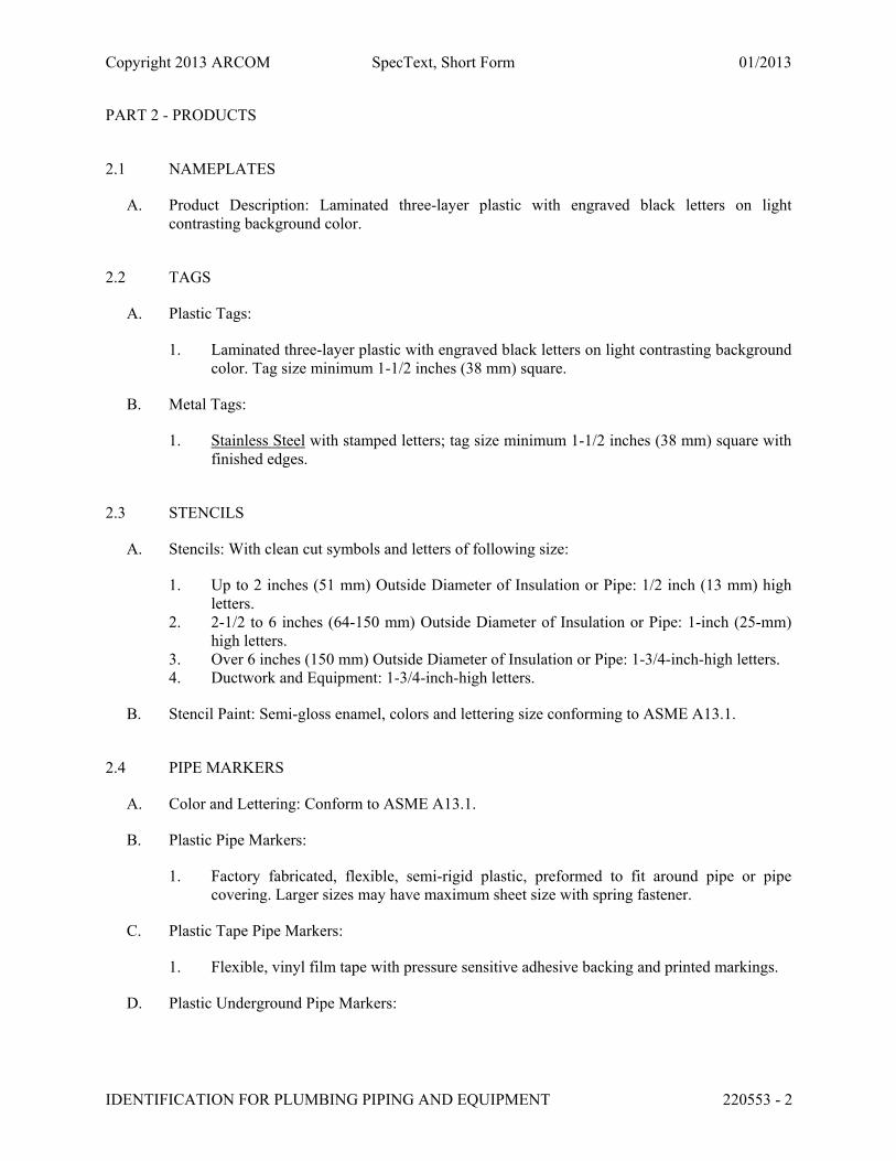
2.1 NAMEPLATES
A. Product Description: Laminated three-layer plastic with engraved black letters on light contrasting background color.
2.2 TAGS
A. Plastic Tags:
1. Laminated three-layer plastic with engraved black letters on light contrasting background color. Tag size minimum 1-1/2 inches (38 mm) square.
B. Metal Tags:
1. Stainless Steel with stamped letters; tag size minimum 1-1/2 inches (38 mm) square with finished edges.
2.3 STENCILS
A. Stencils: With clean cut symbols and letters of following size:
1. Up to 2 inches (51 mm) Outside Diameter of Insulation or Pipe: 1/2 inch (13 mm) high letters.
2. 2-1/2 to 6 inches (64-150 mm) Outside Diameter of Insulation or Pipe: 1-inch (25-mm) high letters.
3. Over 6 inches (150 mm) Outside Diameter of Insulation or Pipe: 1-3/4-inch-high letters. 4. Ductwork and Equipment: 1-3/4-inch-high letters.
B. Stencil Paint: Semi-gloss enamel, colors and lettering size conforming to ASME A13.1.
2.4 PIPE MARKERS
A. Color and Lettering: Conform to ASME A13.1.
B. Plastic Pipe Markers:
1. Factory fabricated, flexible, semi-rigid plastic, preformed to fit around pipe or pipe covering. Larger sizes may have maximum sheet size with spring fastener.
C. Plastic Tape Pipe Markers:
1. Flexible, vinyl film tape with pressure sensitive adhesive backing and printed markings.
D. Plastic Underground Pipe Markers:
Copyright 2013 ARCOM SpecText, Short Form 01/2013
IDENTIFICATION FOR PLUMBING PIPING AND EQUIPMENT 220553 - 3
1. Bright colored continuously printed plastic ribbon tape, minimum 6 inches (150 mm) wide by 4 mil (0.10 mm) thick, manufactured for direct burial service.
2.5 LABELS
A. Description: Aluminum, size 1.9 x 0.75 inches (48 x 19 mm), adhesive backed with printed identification.
END OF SECTION 220553

Copyright 2013 ARCOM SpecText, Short Form 01/2013
EQUIPMENT WIRING CONNECTIONS 260503 - 1
SECTION 260503 - EQUIPMENT WIRING CONNECTIONS
PART 1 - GENERAL
1.1 SUMMARY
A. Section Includes: Electrical connections to equipment.
1.2 SUBMITTALS
A. Product Data: Wiring device manufacturer's catalog information showing dimensions, configurations, and construction.
B. Manufacturer's installation instructions.
1.3 CLOSEOUT SUBMITTALS
A. Project Record Documents: Record actual locations, sizes, and configurations of equipment connections.
1.4 COORDINATION
A. Obtain and review Shop Drawings, product data, manufacturer's wiring diagrams, and manufacturer's instructions for equipment furnished under other Sections.
B. Determine connection locations and requirements.
C. Sequence rough-in of electrical connections to coordinate with installation of equipment.
D. Sequence electrical connections to coordinate with startup of equipment.
PART 2 - EXECUTION
2.1 EXISTING WORK
A. Remove exposed abandoned equipment wiring connections.
B. Disconnect abandoned utilization equipment and remove wiring connections. Remove abandoned components when connected raceway is abandoned and removed. Install blank cover for abandoned boxes and enclosures not removed.
C. Extend existing equipment connections using materials and methods compatible with existing electrical installations, or as specified.

Copyright 2013 ARCOM SpecText, Short Form 01/2013
EQUIPMENT WIRING CONNECTIONS 260503 - 2
2.2 INSTALLATION
A. Make electrical connections.
B. Make conduit connections to equipment using flexible conduit. Use liquidtight flexible conduit with watertight connectors in damp or wet locations.
C. Connect heat-producing equipment using wire and cable with insulation suitable for temperatures encountered.
D. Install receptacle outlet to accommodate connection with attachment plug.
E. Install cord and cap for field-supplied attachment plug.
F. Install strain-relief clamps and fittings for cord connections at outlet boxes and equipment connection boxes.
G. Install disconnect switches, controllers, control stations, and control devices to complete equipment wiring requirements.
H. Install terminal block jumpers to complete equipment wiring requirements.
I. Install interconnecting conduit and wiring between devices and equipment to complete equipment wiring requirements.
2.3 ADJUSTING
A. Cooperate with equipment installers and field service personnel during checkout and starting of equipment to allow testing and balancing and other startup operations.
B. Provide personnel to operate electrical system and checkout wiring connection components and configurations.
END OF SECTION 260503

Copyright 2014 ARCOM SpecText, Short Form 07/2014
SEWER AND MANHOLE TESTING 330130.13 - 1
SECTION 330130.13 - SEWER AND MANHOLE TESTING
PART 1 - GENERAL
1.1 SUMMARY
A. Section Includes:
1. Testing of Gravity Sewer Piping:
a. Low pressure air testing. b. Exfiltration testing. c. Infiltration testing.
2. Testing of pressure piping. 3. Deflection testing of plastic sewer piping. 4. Testing of Manholes:
a. Vacuum testing. b. Exfiltration testing.
1.2 SUBMITTALS
A. Submit following items prior to start of testing:
1. Testing procedures. 2. List of test equipment. 3. Testing sequence schedule. 4. Provisions for disposal of flushing and test water. 5. Certification of test gage calibration. 6. Deflection mandrel drawings and calculations.
B. Test and Evaluation Reports: Indicate results of manhole tests.
PART 2 - PRODUCTS
2.1 TESTING
A. Vacuum Equipment:
1. Vacuum pump. 2. Vacuum line. 3. Vacuum Tester Base:
a. Compression band seal. b. Outlet port.

Copyright 2014 ARCOM SpecText, Short Form 07/2014
SEWER AND MANHOLE TESTING 330130.13 - 2
4. Shutoff valve. 5. Stopwatch. 6. Plugs. 7. Vacuum Gage: Calibrated to 0.1 in. Hg (0.34 kPa).
B. Exfiltration Equipment:
1. Plugs. 2. Pump. 3. Measuring device.
C. Air Equipment:
1. Air compressor. 2. Air supply line. 3. Shutoff valves. 4. Pressure regulator. 5. Pressure relief valve. 6. Stopwatch. 7. Plugs. 8. Pressure Gage: Calibrated to 0.1 psi (0.69 kPa).
D. Infiltration Equipment: Weirs.
E. Hydrostatic Equipment:
1. Hydro pump. 2. Pressure hose. 3. Water meter. 4. Test connections. 5. Pressure relief valve. 6. Pressure Gage: Calibrated to 0.1 psi (0.69 kPa).
F. Deflection Equipment:
1. "Go, no go" mandrels. 2. Pull/retrieval ropes.
PART 3 - EXECUTION
3.1 EXAMINATION
A. Verify that manholes and piping are ready for testing.
B. Verify that trenches are backfilled.
C. Verify that pressure piping thrust restraint system is installed.

Copyright 2014 ARCOM SpecText, Short Form 07/2014
SEWER AND MANHOLE TESTING 330130.13 - 3
3.2 PREPARATION
A. Lamping:
1. Lamp gravity piping after flushing and cleaning. 2. Perform lamping operation by shining light at one end of each pipe section between
manholes. 3. Observe light at other end. 4. Pipe not installed with uniform line and grade will be rejected. 5. Remove and reinstall rejected pipe sections. 6. Reclean and lamp until pipe section is installed to uniform line and grade.
B. Plugs:
1. Plug outlets, wye branches, and laterals. 2. Brace plugs to resist test pressures.
C. Testing of Manholes:
1. Description:
a. If air testing, test whenever possible prior to backfilling to more easily locate leaks. b. Repair both outside and inside of joint to ensure permanent seal. c. Test manholes with manhole frame set in place.
2. Vacuum test per ASTM C1244 (C1244M) and following:
a. Plug pipe openings; securely brace plugs and pipe. b. Inflate compression band to create seal between vacuum base and structure. c. Connect vacuum pump to outlet port with valve open, then draw vacuum. d. Close valve. e. Manhole Test Duration in Seconds:
1) Diameter 4 Feet (1.2 m):60. 2) Diameter 5 Feet (1.5 m):75. 3) Diameter 6 Feet (1.8 m):90.
f. Record vacuum drop during test period.
3. Exfiltration Testing:
a. Plug pipes in manhole. b. Remove water from manhole. c. Observe plugs over period of not less than two hours to ensure that there is no
leakage into manhole. d. Determine ground water level outside manhole. e. Fill manhole with water. f. Prior to testing, allow manhole to soak from minimum of four hours. g. After soak period, adjust water level inside manhole. h. Measure water level from top of manhole frame.

Copyright 2014 ARCOM SpecText, Short Form 07/2014
SEWER AND MANHOLE TESTING 330130.13 - 4
i. At end of four-hour testing period, again measure water level from top of manhole frame; compute drop in water level during testing period.
j. Manhole exfiltration test is considered satisfactory when drop in water level is less than following:
1) Manhole Depth of 4 feet (1.2 m):
a) Diameter of 4 feet (1.2 m):0.11 inch (3 mm). b) Diameter of 5 feet (1.5 m):0.14 inch (4 mm). c) Diameter of 6 feet (1.8 m): 0.17 inch (5 mm).
2) Manhole Depth of 6 feet (1.5 m):
a) Diameter of 4 feet (1.2 m):0.17 inch (5 mm). b) Diameter of 5 feet (1.5 m): 0.21 inch (6 mm). c) Diameter of 6 feet (1.8 m):0.26 inch (8 mm).
3) Manhole Depth of 8 feet (2.4 m):
a) Diameter of 4 feet (1.2 m):0.23 inch (7 mm). b) Diameter of 5 feet (1.5 m): 0.29 inch (9 mm). c) Diameter of 6 feet (1.8 m): 0.35 inch (11 mm).
4) Manhole Depth of 10 feet (3.0 m):
a) Diameter of 4 feet (1.2 m):0.28 inch (9 mm). b) Diameter of 5 feet (1.5 m): 0.35 inch (11 mm). c) Diameter of 6 feet (1.8 m):0.42 inch (13 mm).
5) Manhole Depth of 12 feet (3.7 m):
a) Diameter of 4 feet (1.2 m):0.34 inch (10 mm). b) Diameter of 5 feet (1.5 m):0.43 inch (13 mm). c) Diameter of 6 feet (1.8 m):0.51 inch (16 mm).
6) Manhole Depth of 14 feet (4.3 m):
a) Diameter of 4 feet (1.2 m):0.40 inch (12 mm). b) Diameter of 5 feet (1.5 m):0.50 inch (15 mm). c) Diameter of 6 feet (1.8 m):0.60 inch (18 mm).
7) Manhole Depth of 16 feet (4.9 m):
a) Diameter of 4 feet (1.2 m):0.45 inch (14 mm). b) Diameter of 5 feet (1.5 m):0.56 inch (17 mm). c) Diameter of 6 feet (1.8 m): 0.68 inch (21 mm).
8) Manhole Depth of 18 feet (5.5 m):
a) Diameter of 4 feet (1.2 m):0.51 inch (16 mm). b) Diameter of 5 feet (1.5 m):0.64 inch (19 mm). c) Diameter of 6 feet (1.8 m):0.77 inch (23 mm).

Copyright 2014 ARCOM SpecText, Short Form 07/2014
SEWER AND MANHOLE TESTING 330130.13 - 5
9) Manhole Depth of 20 feet (6.1 m):
a) Diameter of 4 feet (1.2 m):0.57 inch (17 mm). b) Diameter of 5 feet (1.5 m):0.71 inch (22 mm). c) Diameter of 6 feet (1.8 m):0.86 inch (26 mm).
10) Manhole Depth of 22 feet (6.7 m):
a) Diameter of 4 feet (1.2 m):0.62 inch (19 mm). b) Diameter of 5 feet (1.5 m):0.78 inch (24 mm). c) Diameter of 6 feet (1.8 m):0.93 inch (28 mm).
11) Manhole Depth of 24 feet (7.3 m):
a) Diameter of 4 feet (1.2 m):0.68 inch (21 mm). b) Diameter of 5 feet (1.5 m):0.85 inch (26 mm). c) Diameter of 6 feet (1.8 m):1.02 inch (31 mm).
12) Manhole Depth of 26 feet (7.9 m):
a) Diameter of 4 feet (1.2 m):0.74 inch (23 mm). b) Diameter of 5 feet (1.5 m):0.93 inch (28 mm). c) Diameter of 6 feet (1.8 m):1.11 inch (34 mm).
13) Manhole Depth of 28 feet (8.5 m):
a) Diameter of 4 feet (1.2 m):0.79 inch (24 mm). b) Diameter of 5 feet (1.5 m):0.99 inch (30 mm). c) Diameter of 6 feet (1.8 m):1.19 inch (36 mm).
14) Manhole Depth of 30 feet (9.1 m):
a) Diameter of 4 feet (1.2 m):0.85 inch (26 mm). b) Diameter of 5 feet (1.5 m):1.06 inch (32 mm). c) Diameter of 6 feet (1.8 m):1.28 inch (39 mm).
4. If unsatisfactory testing results are achieved, repair manhole and retest until result meets criteria.
5. Repair visible leaks regardless of quantity of leakage.
END OF SECTION 330130.13

Copyright 2015 ARCOM SpecText, Short Form 01/2015
MANHOLES AND STRUCTURES 330513 - 1
SECTION 330513 - MANHOLES AND STRUCTURES
PART 1 - GENERAL
1.1 SUMMARY
A. Section Includes: 1. Modular precast concrete manholes and structures with tongue-and-groove joints, covers,
anchorage, and accessories.
1.2 SUBMITTALS
A. Product Data: Manhole covers, component construction, features, configuration, dimensions.
B. Shop Drawings:
1. Structure locations and elevations. 2. Sizes and elevations of piping, conduit, penetrations.
C. Manufacturer's Certificate: Products meet or exceed specified requirements.
D. Manufacturer Instructions: Installation requirements, including storage and handling procedures.
E. Field Quality-Control Submittals: Indicate results of Contractor-furnished tests and inspections.
F. Qualifications Statements:
1. Qualifications for manufacturer and installer. 2. Manufacturer's approval of installer.
1.3 QUALITY ASSURANCE
A. Perform Work per imperial county standards.
1.4 DELIVERY, STORAGE, AND HANDLING
A. Comply with precast concrete manufacturer's instructions and ASTM C913 for unloading, storing, and moving precast manholes and drainage structures.
B. Storage:
1. Store precast concrete manholes and drainage structures to prevent damage to Owner's property or other public or private property.
2. Repair property damaged from materials storage.

Copyright 2015 ARCOM SpecText, Short Form 01/2015
MANHOLES AND STRUCTURES 330513 - 2
PART 2 - PRODUCTS
2.1 MANHOLES AND STRUCTURES 1. Furnish materials per imperial county standards.
B. Manhole and Structure Sections:
1. Description: Reinforced precast concrete conforming to ASTM C478 (C478M) with gaskets conforming to ASTM C923 (C923M).
2. Joints for Precast Manholes and Structures:
a. Conforming to ASTM C913. b. Maximum Leakage: 0.025 gal. ([94.6 ml]) per hour per foot (0.3 m) of joint at 3
feet (91 cm) of head.
C. Shape: Cylindrical.
D. Pipe Entry: Furnish openings as required.
E. Structure Joint Gaskets:
1. ASTM C361 (C361M). 2. Material: Rubber.
2.2 FRAMES AND COVERS 1. Furnish materials per imperial county standards.
PART 3 - EXECUTION
3.1 EXAMINATION
A. Verify that items provided by other Sections of Work are properly sized and located.
B. Verify that built-in items are in proper location and are ready for roughing into Work.
C. Verify correct size of manhole and structure excavation.
3.2 PREPARATION
A. Mark each precast structure by indentation or waterproof paint showing date of manufacture, manufacturer, and identifying symbols and numbers as indicated to indicate its intended use.
B. Coordinate placement of inlet and outlet pipe or duct sleeves required by other Sections.
C. Do not install manholes and structures where Site conditions induce loads exceeding structural capacity of manholes or structures.

Copyright 2015 ARCOM SpecText, Short Form 01/2015
MANHOLES AND STRUCTURES 330513 - 3
D. Inspect precast concrete manholes and structures immediately prior to placement in excavation to verify that they are internally clean and free from damage; remove and replace damaged units.
3.3 INSTALLATION
A. Excavation and Backfill:
1. Excavate for manholes and structures as specified. 2. Provide clearance around sidewalls of manhole or structure for construction operations. 3. If groundwater is encountered, prevent accumulation of water in excavations; place
manhole or structure in dry trench. 4. Where possibility exists of watertight manhole or structure becoming buoyant in flooded
excavation, anchor manhole or structure to avoid flotation, as approved by Engineer.
B. Precast Concrete Manholes and Structures:
1. Lift precast components at lifting points designated by manufacturer. 2. When lowering manholes into excavations and joining pipe to units, take precautions to
ensure that interior of pipeline and structure remains clean. 3. Set precast structures, bearing firmly and fully on crushed stone bedding, compacted or
on other support system as indicated. 4. Assembly:
a. Assemble multi-section manholes and structures by lowering each section into excavation.
b. Install rubber gasket joints between precast sections per manufacturer's recommendations.
c. Lower, set level, and firmly position base section before placing additional sections.
5. Remove foreign materials from joint surfaces and verify sealing materials are placed properly.
6. Maintain alignment between sections by using guide devices affixed to lower section. 7. Joint sealing materials may be installed on Site or at manufacturer's plant. 8. Verify that installed manholes meet required alignment and grade. 9. Remove knockouts or cut structure to receive piping without creating openings larger
than required to receive pipe; fill annular spaces with mortar. 10. Cut pipe flush with interior of structure. 11. Shape inverts through manholes as indicated.
END OF SECTION 330513
Copyright 2014 ARCOM SpecText, Short Form 04/2014
PRESSURE PIPING TIED JOINT RESTRAINT SYSTEM 330519 - 1
SECTION 330519 - PRESSURE PIPING TIED JOINT RESTRAINT SYSTEM
PART 1 - GENERAL
1.1 SUMMARY
A. Section Includes:
1. Tied joint restraint system.
1.2 SUBMITTALS
A. Product Data: Restrained joint details and installation instructions.
B. Shop Drawings:
1. Restrained joint details, materials being used, and locations. 2. Layout drawings showing piece numbers and locations.
C. Samples: one sample of joint restraint parts.
D. Manufacturer's Certificate: Products meet or exceed specified requirements.
E. Delegated Design Submittals: 1. Use joint restraint devices specifically designed for applications described in
manufacturer's data.
F. Manufacturer Instructions: Installation requirements, including storage and handling procedures.
G. Qualifications Statement:
1. Qualifications for manufacturer, fabricator, and licensed professional.
1.3 CLOSEOUT SUBMITTALS
A. Project Record Documents: Record actual locations of joint restraints.
1.4 QUALITY ASSURANCE
A. Perform Work according to AWWA standards.
1.5 DELIVERY, STORAGE, AND HANDLING
A. Store materials according to manufacturer instructions.

Copyright 2014 ARCOM SpecText, Short Form 04/2014
PRESSURE PIPING TIED JOINT RESTRAINT SYSTEM 330519 - 2
PART 2 - PRODUCTS
2.1 PERFORMANCE AND DESIGN CRITERIA
A. Provide pressure pipeline with restrained joints at each bends, tees, and changes in direction.
2.2 TIED JOINT RESTRAINT SYSTEMS
A. Manufacturers:
1. EBAA 2. Substitutions: Permitted.
2.3 MATERIALS
A. Steel:
1. High Strength Low-Alloy Steel: Comply with ASTM A588 (A588M), heat-treated.
2.4 FINISHES
A. Zinc-Plated or Galvanized Steel:
1. Factory applied. 2. Comply with ASTM B633 for electrodeposited coating of zinc on steel. 3. Comply with ASTM A153 (A153M) for galvanizing iron and steel hardware. 4. Galvanizing:
a. Comply with ASTM A123 (A123M). b. Hot dip galvanize after fabrication.
PART 3 - EXECUTION
3.1 EXAMINATION
A. Verify that pipe and fittings are ready to receive Work.
3.2 INSTALLATION
A. Install pipe and fittings according to AWWA C600.
B. Install joint restraint system such that joints are mechanically locked together to prevent joint separation.

Copyright 2014 ARCOM SpecText, Short Form 04/2014
PRESSURE PIPING TIED JOINT RESTRAINT SYSTEM 330519 - 3
END OF SECTION 330519

Copyright 2014 ARCOM SpecText, Short Form 10/2014
UTILITY IDENTIFICATION 330526 - 1
SECTION 330526 - UTILITY IDENTIFICATION
PART 1 - GENERAL
1.1 SUMMARY
A. Section Includes:
1. Plastic ribbon tape for placement above direct-buried utility. 2. Trace wire for placement above direct-buried utility.
1.2 SUBMITTALS
A. Product Data: Manufacturer's catalog information for each product required.
1.3 CLOSEOUT SUBMITTALS
A. Project Record Documents: Record actual locations of tagged valves.
PART 2 - PRODUCTS
2.1 RIBBON TAPE
A. Manufacturers: 1. Substitutions: Permitted
B. Description:
1. Material: Polyethylene. 2. Brightly colored, continuously printed. 3. Manufactured for direct burial service.
2.2 TRACE WIRE
A. Manufacturers: 1. PermittedNot permitted

Copyright 2014 ARCOM SpecText, Short Form 10/2014
UTILITY IDENTIFICATION 330526 - 2
PART 3 - EXECUTION
3.1 INSTALLATION
A. According to manufacturer instructions.
B. Installation Standards: Install Work according to Imperial County standards.
END OF SECTION 330526

Copyright 2014 ARCOM SpecText, Short Form 04/2014
SITE WATER UTILITY DISTRIBUTION PIPING 331116 - 1
SECTION 331116 - SITE WATER UTILITY DISTRIBUTION PIPING
PART 1 - GENERAL
1.1 SUMMARY
A. Section Includes:
1. Pipe and fittings for public water line, including potable water line. 2. Valves: Gate, and swing check. 3. Positive displacement meters. 4. Underground pipe markers. 5. Valve boxes. 6. Bedding and cover materials.
1.2 SUBMITTALS
A. Product Data: Pipe materials, pipe fittings, valves, and accessories.
B. Shop Drawings: Piping layout, including piping specialties.
C. Include physical samples for selction of finish, color, texture, and other properties.
D. Manufacturer’s Certificate: Products meet or exceed specified requirements
E. Field Quality-Control Submittals: Indicate results of Contractor-furnished tests and inspections.
1.3 CLOSEOUT SUBMITTALS
A. Project Record Documents: Record actual locations of piping mains, valves, connections, thrust restraints, and invert elevations.
B. Identify and describe unexpected variations to subsoil conditions or discovery of uncharted utilities.
1.4 QUALITY ASSURANCE
A. Valves: Mark valve body with manufacturer’s name and pressure rating.
PART 2 - PRODUCTS
2.1 WATER PIPING
A. Flanged Ductile Iron Pipe:

Copyright 2014 ARCOM SpecText, Short Form 04/2014
SITE WATER UTILITY DISTRIBUTION PIPING 331116 - 2
1. Comply with AWWA C151 2. Bituminous Outside Coating: Comply with AWWA C151 for fusion bonded expoxy. 3. Pipe Mortar Lining:
a. Comply with AWWA C104 b. Double thickness
4. Fittings:
a. Material: Ductile iron AWWA C110.
5. Flanged Joints:
a. Comply with AWWA C115. b. Provide rubber gasket with rods.
6. Jackets: AWWA C105, polyethylene jacket.
B. PVC Pipe:
1. Comply with AWWA C900, Class 200. 2. Fittings:
a. Material: Cast iron. b. Comply with AWWA C111.
3. Joints:
a. Comply with ASTM D3139. b. Provide compression gasket ring.
END OF SECTION 331116

Copyright 2014 ARCOM SpecText, Short Form 04/2014
WATER UTILITY DISTRIBUTION VALVES 331216 - 1
SECTION 331216 - WATER UTILITY DISTRIBUTION VALVES
PART 1 - GENERAL
1.1 SUMMARY
A. Section Includes:
1. Valves. 2. Valve boxes.
1.2 SUBMITTALS
A. Product Data: Manufacturer's latest published literature. Include illustrations, installation and maintenance instructions, and parts lists.
B. Shop Drawings: Description of proposed installation.
C. Manufacturer's Certificate: Products meet or exceed specified requirements.
D. Manufacturer Instructions: Installation requirements, including storage and handling procedures.
E. Field Quality-Control Submittals: Indicate results of Contractor-furnished tests and inspections.
F. Qualifications Statements:
1. Qualifications for manufacturer and installer. 2. Manufacturer's approval of installer.
1.3 CLOSEOUT SUBMITTALS
A. Project Record Documents: Record actual locations of valves.
1.4 QUALITY ASSURANCE
A. Cast manufacturer's name, pressure rating, and year of fabrication into valve body.
1.5 DELIVERY, STORAGE, AND HANDLING
A. Prepare valves and accessories for shipment according to applicable AWWA standards.
B. Seal valve and ends to prevent entry of foreign matter.
C. Storage:

Copyright 2014 ARCOM SpecText, Short Form 04/2014
WATER UTILITY DISTRIBUTION VALVES 331216 - 2
1. Store materials in areas protected from weather, moisture, or other potential damage. 2. Do not store materials directly on ground.
D. Handle products carefully to prevent damage to interior or exterior surfaces.
PART 2 - PRODUCTS
2.1 RESILIENT WEDGE GATE VALVES
A. Manufacturers: 1. Substitutions: Permitted.
B. Description:
1. Comply with AWWA C509. 2. Materials:
a. Body: Ductile iron
3. Seats: Resilient. 4. Stem:
a. Type: Non-rising. b. Material: Bronze.
5. Operation:
a. Square operating nut or handwheel as directed by plans. b. Open counterclockwise unless otherwise indicated.
6. End Connections: Flanged. 7. Coatings:
a. Comply with AWWA C550. b. Interior and exterior.
8. Pressure Rating:
a. Eight-inch Diameter: 150 psig.
2.2 ACCESSORIES
A. Concrete for Thrust Restraints: Concrete type as specified in Section 033000 - Cast-in-Place Concrete.
B. Valve Box Aligner: High-strength plastic device designed to automatically center valve box base and to prevent it from shifting off center during backfilling.

Copyright 2014 ARCOM SpecText, Short Form 04/2014
WATER UTILITY DISTRIBUTION VALVES 331216 - 3
PART 3 - EXECUTION
3.1 EXAMINATION
A. Verify that invert elevations of existing work prior to excavation and installation of valves are as indicated.
3.2 PREPARATION
A. Identify required lines, levels, contours, and datum locations.
B. Do not interrupt existing utilities without permission and without making arrangements to provide temporary utility services.
1. Notify Engineer not less than 14 days in advance of proposed utility interruption. 2. Do not proceed without written permission from Engineer.
3.3 INSTALLATION
A. Perform trench excavation, backfilling, and compaction as specified in Section 331113 - Public Water Utility Distribution Piping.
B. Install valves in conjunction with pipe laying.
C. Set valves plumb.
D. Provide buried valves with valve boxes installed flush with finished grade.
E. Disinfection of Water Piping System:
1. Flush and disinfect system as specified in Section 331300 - Disinfecting of Water Utility Distribution.
3.4 FIELD QUALITY CONTROL
A. Pressure test water distribution system according to AWWA C600.
END OF SECTION 331216

Copyright 2014 ARCOM SpecText, Short Form 04/2014
DISINFECTING OF WATER UTILITY DISTRIBUTION 331300 - 1
SECTION 331300 - DISINFECTING OF WATER UTILITY DISTRIBUTION
PART 1 - GENERAL
1.1 SUMMARY
A. Section Includes:
1. Disinfection of potable water distribution system. 2. Testing and reporting of results.
1.2 SUBMITTALS
A. Product Data: Procedures, proposed chemicals, and treatment levels.
B. Manufacturer's Certificate: Products meet or exceed specified requirements.
C. Certify that cleanliness of water distribution system meets or exceeds specified requirements.
D. Certify that water conforms or fails to conform to bacterial standards of authority having jurisdiction.
E. Certify that water conforms to quality standards of authority having jurisdiction.
F. Test and Evaluation Reports: Indicate testing results comparative to specified requirements.
G. Field Quality-Control Submittals: Indicate results of Contractor-furnished tests and inspections.
H. Qualifications Statements:
1. Qualifications for water treatment firm and testing firm.
1.3 CLOSEOUT SUBMITTALS
A. Disinfection Report:
1. Type and form of disinfectant used. 2. Date and time of disinfectant injection start and time of completion. 3. Test locations. 4. Name of person collecting samples. 5. Initial and 24-hour disinfectant residuals in treated water in ppm for each outlet tested. 6. Date and time of flushing start and completion. 7. Disinfectant residual after flushing in ppm for each outlet tested.
B. Bacteriological Report:
1. Date issued, project name, and testing laboratory name, address, and telephone number.

Copyright 2014 ARCOM SpecText, Short Form 04/2014
DISINFECTING OF WATER UTILITY DISTRIBUTION 331300 - 2
2. Time and date of water sample collection. 3. Name of person collecting samples. 4. Test locations. 5. Initial and 24-hour disinfectant residuals in ppm for each outlet tested. 6. Coliform bacteria test results for each outlet tested. 7. Submit bacteriologist's signature and authority associated with testing.
1.4 QUALITY ASSURANCE
A. Perform Work per AWWA C651.
PART 2 - PRODUCTS
2.1 DISINFECTION CHEMICALS
A. Chemicals:
1. Hypochlorite: Comply with AWWA B300.
PART 3 - EXECUTION
3.1 EXAMINATION
A. Verify that piping system has been cleaned, inspected, and pressure tested.
B. Perform scheduling and disinfecting activity with startup, water pressure testing, adjusting and balancing, and demonstration procedures, including coordination with related systems.
3.2 INSTALLATION
A. Provide and attach required equipment to perform Work of this Section.
B. Perform disinfection of water distribution system and installation of system and pressure testing as specified in Section 331116 - Site Water Utility Distribution Piping.
C. Introduce treatment into piping system.
D. Maintain disinfectant in system for 24 hours.
E. Flush, circulate, and clean until required cleanliness is achieved using municipal domestic water.
F. Replace permanent system devices that were removed for disinfection.

Copyright 2014 ARCOM SpecText, Short Form 04/2014
DISINFECTING OF WATER UTILITY DISTRIBUTION 331300 - 3
3.3 FIELD QUALITY CONTROL
A. Disinfection, Flushing, and Sampling:
1. Disinfect pipeline installation per AWWA C651. 2. Use of liquid chlorine is not permitted. 3. Upon completion of retention period required for disinfection, flush pipeline until
chlorine concentration in water leaving pipeline is no higher than that generally prevailing in existing system or is acceptable for domestic use.
4. Disposal:
a. Legally dispose of chlorinated water. b. When chlorinated discharge may cause damage to environment, apply neutralizing
chemical to chlorinated water to neutralize chlorine residual remaining in water.
5. After final flushing and before pipeline is connected to existing system or placed in service, employ an approved independent testing laboratory to sample, test, and certify that water quality meets quality standards of authority having jurisdiction.
END OF SECTION 331300

Copyright 2016 ARCOM SpecText, Short Form 07/2016
SWING CHECK VALVES 400565.23 - 1
SECTION 400565.23 - SWING CHECK VALVES
PART 1 - GENERAL
1.1 SUMMARY
A. Section Includes: Swing check valves 3 inches (75 mm) and larger.
1.2 SUBMITTALS
A. Product Data: Manufacturer's catalog information, indicating materials of construction and compliance with indicated standards.
B. Manufacturer's Certificate: Products meet or exceed specified requirements.
C. Source Quality-Control Submittals: Indicate results of factory tests and inspections.
D. Field Quality-Control Submittals: Indicate results of Contractor-furnished tests and inspections.
E. Qualifications Statement:
1. Qualifications for manufacturer.
1.3 CLOSEOUT SUBMITTALS
A. Project Record Documents: Record actual locations of piping, valves and other appurtenances, connections, and invert elevations.
1.4 QUALITY ASSURANCE
A. Materials in Contact with Potable Water: Certified per NSF 61 and NSF 372.
B. Perform Work per standards.
1.5 DELIVERY, STORAGE, AND HANDLING
A. Store materials per manufacturer instructions.
B. Protection:
1. Protect materials from moisture and dust by storing in clean, dry location remote from construction operations areas.
2. Protect valves and appurtenances by storing off ground. 3. Provide additional protection per manufacturer instructions.

Copyright 2016 ARCOM SpecText, Short Form 07/2016
SWING CHECK VALVES 400565.23 - 2
1.6 EXISTING CONDITIONS
A. Field Measurements:
1. Verify field measurements prior to fabrication. 2. Indicate field measurements on Shop Drawings.
1.7 WARRANTY
A. Furnish 5-year manufacturer's warranty for swing check valves.
PART 2 - PRODUCTS
2.1 SWING CHECK VALVES 1. Furnish materials per standards.
B. Description:
1. Type: Swing, resilient seated, with outside lever and adjustable spring. 2. Size: 3 inches (76 mm) and larger. 3. Comply with AWWA C508. 4. Minimum Working Pressure: As indicated. 5. Maximum Fluid Temperature: As indicated. 6. Flow Area: Full open equal to connecting nominal pipe diameter. 7. Check Valves 3 Inches and Larger: Furnish with adjustable air cushion chambers. 8. Mounting: Horizontal or vertical. 9. End Connections: Flanged, ASME B16.1
C. Materials:
1. Body and Cover: Ductile iron, ASTM A536. 2. Disc: Ductile iron, ASTM A536 3. Seat: Field replaceable, Type 304 stainless steel. 4. Chamber and Plunger: [Bronze, ASTM B62] <________>. 5. Hinge Pin and Key: Stainless steel. 6. Packing and O-Ring: [Buna-N] <________>. 7. Rubber Components: Buna-N. 8. Connecting Hardware: Type 304 stainless steel.
2.2 SOURCE QUALITY CONTROL
A. Testing:
1. Hydrostatically test check valves at twice rated pressure per AWWA C508. 2. Permitted Leakage at Indicated Working Pressure: None.
B. Certificate of Compliance:

Copyright 2016 ARCOM SpecText, Short Form 07/2016
SWING CHECK VALVES 400565.23 - 3
1. If manufacturer is approved by authorities having jurisdiction, submit certificate of compliance indicating Work performed at manufacturer's facility conforms to Contract Documents.
2. Specified shop tests are not required for Work performed by approved manufacturer.
PART 3 - EXECUTION
3.1 EXAMINATION
A. Verify that field dimensions are as indicated.
B. Inspect existing flanges for nonstandard bolt-hole configurations or design, and verify that new valve and flange mate properly.
3.2 PREPARATION
A. Surface Preparation:
1. Touch up shop-primed surfaces with primer as specified. 2. Solvent-clean surfaces that are not shop primed. 3. Clean surfaces to remove loose rust, mill scale, and other foreign substances by power
wire brushing. 4. Prime surfaces as specified in Section.
3.3 INSTALLATION
A. Per AWWA C508 and manufacturer instructions.
B. Dielectric Fittings: Provide between dissimilar metals.
3.4 FIELD QUALITY CONTROL
A. Inspection:
1. Inspect for damage to valve lining or coating and for other defects that may be detrimental as determined by Architect/Engineer.
2. Repair damaged valve or provide new, undamaged valve. 3. After installation, inspect for proper supports and interferences.
B. Pressure Testing: As indicated.
END OF SECTION 400565.23

Copyright 2015 ARCOM SpecText, Short Form 01/2015
MAGNETIC FLOW METERS 407113 - 1
SECTION 407113 - MAGNETIC FLOW METERS
PART 1 - GENERAL
1.1 SUMMARY
A. Section Includes:
1. Magnetic flow meters.
1.2 SUBMITTALS
A. Product Data: Manufacturer information for system materials and component equipment, including connection requirements.
B. Shop Drawings:
1. System materials and component equipment. 2. Installation requirements and other details.
C. Manufacturer's Certificate: Products meet or exceed specified requirements.
D. Source Quality-Control Submittals: Indicate results of factory tests and inspections.
E. Field Quality-Control Submittals: Indicate results of Contractor-furnished tests and inspections.
F. Manufacturer Reports: Indicate that equipment has been installed according to manufacturer instructions.
G. Qualifications Statement:
1. Qualifications for manufacturer.
1.3 CLOSEOUT SUBMITTALS
A. Project Record Documents: Record actual locations and final orientation of equipment and accessories.
1.4 QUALITY ASSURANCE
A. Ensure that materials of construction of wetted parts are compatible with process liquid.
B. Materials in Contact with Potable Water: Certified to NSF 61 and NSF 372.
C. Perform Work per standards.

Copyright 2015 ARCOM SpecText, Short Form 01/2015
MAGNETIC FLOW METERS 407113 - 2
1.5 DELIVERY, STORAGE, AND HANDLING
A. Store equipment per manufacturer instructions.
B. Protection:
1. Protect materials from moisture and dust by storing in clean, dry location remote from construction operations areas.
2. Provide additional protection per manufacturer instructions.
1.6 WARRANTY
A. Furnish 5-year manufacturer's warranty for magnetic flow meters and appurtenant devices.
PART 2 - PRODUCTS
2.1 SYSTEM DESCRIPTION
A. Furnish sensors, field preamplifiers, signal conditioners, offset and span adjustments, amplifiers, transducers, transmitters, control devices, interconnecting cables, and unit conversions and algorithms as required for application.
2.2 MAGNETIC FLOW METERS 1. Furnish materials per standards.
B. Description: Low-frequency, electromagnetic induction-type flow meter, producing a linear signal directly proportional to flow rate, consisting of flow tube, signal cable, and transmitter.
C. Performance and Design Criteria:
1. Design: Per AWWA M33.
D. Flow Rate Range: 0 to 2,000 gpm.
E. Size: As indicated on Drawings.
F. Flow Tubes:
1. Material: Type 304 stainless steel with polyurethane liner. 2. Length: As indicated on Drawings. 3. End Connections: Flanged, ASME B16.1, carbon steel.
G. Electrodes:
1. Type 316L stainless steel. 2. Self-cleaning.
H. Accuracy: Plus or minus 1 percent of actual flow rate over a <100:500> range.

Copyright 2015 ARCOM SpecText, Short Form 01/2015
MAGNETIC FLOW METERS 407113 - 3
I. Provide adjustment for zero and span.
J. Accessories:
1. Provide automatic, nonmechanical electrode cleaning system without taking meter out of service.
2. Furnish cable between transmitter and receiver.
2.3 TRANSMITTERS
A. Transmitter Output:
1. 4- to 20-mA dc analog signal. 2. Accuracy: Plus or minus 1 percent of full scale.
B. Housing Material: Cast aluminum.
C. HMI:
1. Touch-screen programming, functioning through enclosure window without opening enclosure.
2. Display:
a. Size: Four lines by 16 characters. b. Type: Backlit digital display. c. User-selectable engineering units. d. Readout of diagnostic error messages.
D. Mounting:
1. Integral or remote mounting up to 5 feet from flow meter.
E. Transmitter Communication Interface: PROFIBUS
F. Communication Firmware and Software
G. Accessories:
1. Current signal output simulation. 2. Empty pipe detection. 3. Self-diagnostics. 4. Automatic zero adjustment. 5. Stainless-steel sunshield. 6. Signal Cable: Provided by flow meter manufacturer.
2.4 INDICATORS 1. Furnish materials per standards.
B. Description:

Copyright 2015 ARCOM SpecText, Short Form 01/2015
MAGNETIC FLOW METERS 407113 - 4
1. Integrally mounted in transmitter housing. 2. Scale: Graduated.
2.5 RECORDERS 1. Furnish materials per standards.
2.6 INTEGRATORS 1. Furnish materials per standards.
2.7 OPERATION
A. Control Power:
1. Wiring: As specified. 2. 120-V ac, single phase, 60 Hz. 3. Furnish local transformers as required.
B. Enclosures: As indicated.
2.8 SOURCE QUALITY CONTROL
A. Provide shop inspection and testing of meters per AWWA M6.
B. Certificate of Compliance:
1. If manufacturer is approved by authorities having jurisdiction, submit certificate of compliance indicating Work performed at manufacturer's facility conforms to Contract Documents.
2. Specified shop tests are not required for Work performed by approved manufacturer.
PART 3 - EXECUTION
3.1 EXAMINATION
A. Verify that items provided by other Sections of Work are ready to receive Work of this Section.
3.2 INSTALLATION
A. Coordinate location and orientation of flow meter with final equipment installations.
B. Ensure that instruments are located to be easily accessible for maintenance.

Copyright 2015 ARCOM SpecText, Short Form 01/2015
MAGNETIC FLOW METERS 407113 - 5
FIELD QUALITY CONTROL
C. Testing:
1. Test and calibrate flow meter to demonstrate that it meets specified accuracy requirements.
2. Comply with AWWA M6.
D. Equipment Acceptance: Adjust, repair, modify, or replace components failing to perform as specified and rerun tests.
3.3 DEMONSTRATION
A. Demonstrate equipment startup, shutdown, routine maintenance, and emergency repair procedures to Owner's personnel.
END OF SECTION 407113

Copyright 2015 ARCOM SpecText, Short Form 01/2015
GAUGE-PRESSURE TRANSMITTERS 407326 - 1
SECTION 407326 - GAUGE-PRESSURE TRANSMITTERS
PART 1 - GENERAL
1.1 SUMMARY
A. Section Includes: Gage-pressure transmitters.
1.2 SUBMITTALS
A. Product Data: Manufacturer information for system materials and component equipment, including connection requirements.
B. Shop Drawings:
1. System materials and component equipment. 2. Installation requirements and other details.
C. Manufacturer's Certificate: Products meet or exceed specified requirements.
D. Source Quality-Control Submittals: Indicate results of factory tests and inspections.
E. Field Quality-Control Submittals: Indicate results of Contractor-furnished tests and inspections.
F. Qualifications Statement:
1. Qualifications for manufacturer.
1.3 CLOSEOUT SUBMITTALS
A. Project Record Documents: Record actual locations of equipment and accessories.
1.4 MAINTENANCE MATERIAL SUBMITTALS
A. Extra Stock Materials: Two spare transmitters complete with diaphragm seals.
1.5 QUALITY ASSURANCE
A. Ensure that materials of construction of wetted parts are compatible with process liquid.
B. Materials in Contact with Potable Water: Certified to NSF 61 and NSF 372.
C. Perform Work according Imperial County Department of Public Works Standards.

Copyright 2015 ARCOM SpecText, Short Form 01/2015
GAUGE-PRESSURE TRANSMITTERS 407326 - 2
D. Manufacturer: Company specializing in manufacturing products specified in this Section with three years' experience.
1.6 DELIVERY, STORAGE, AND HANDLING
A. Store materials according to manufacturer instructions.
B. Protection:
1. Protect materials from moisture and dust by storing in clean, dry location remote from construction operations areas.
2. Provide additional protection according to manufacturer instructions.
1.7 WARRANTY
A. Furnish five-year manufacturer's warranty for gage-pressure transmitters.
PART 2 - PRODUCTS
2.1 GAGE-PRESSURE TRANSMITTERS
A. Manufacturers:
1. ABB, Honeywell International, Omega 2. Substitutions: Permitted.
B. Description:
1. Excitation:
a. 9- to 30-V dc. b. Overvoltage protected.
2. Accuracy: Plus or minus 0.25% percent. 3. Output Signal: 4 to 20 mA dc. 4. Operating Temperature Range: 25 to 150 degrees F 5. Response Time: Less than 30 ms (adjustable). 6. Materials: Type 316 stainless steel. 7. Location: As indicated.
C. Mounting: Pipe.
D. Furnish cable, field preamplifiers, and signal conditioners as required to maintain accuracy from transducer to terminal device.
E. Operation:
1. Control Power:

Copyright 2015 ARCOM SpecText, Short Form 01/2015
GAUGE-PRESSURE TRANSMITTERS 407326 - 3
a. Wiring: As specified in Section 260503 - Equipment Wiring Connections. b. 120-V ac, single phase, 60 Hz. c. Furnish local transformers as required.
2. Enclosures: NEMA 250 Type As indicated.
2.2 SOURCE QUALITY CONTROL
A. Provide shop inspection and testing of completed assembly.
B. Certificate of Compliance:
1. If manufacturer is approved by authorities having jurisdiction, submit certificate of compliance indicating Work performed at manufacturer's facility conforms to Contract Documents.
2. Specified shop tests are not required for Work performed by approved manufacturer.
PART 3 - EXECUTION
3.1 EXAMINATION
A. Verify that items provided by other Sections of Work are ready to receive Work of this Section.
3.2 INSTALLATION
A. According to manufacturer instructions.
3.3 FIELD QUALITY CONTROL
A. Equipment Acceptance: Adjust, repair, modify, or replace components failing to perform as specified and rerun tests.
3.4 DEMONSTRATION
A. Demonstrate equipment startup, shutdown, routine maintenance, and emergency repair procedures to Owner's personnel.
ND OF SECTION 407326

Copyright 2015 ARCOM SpecText, Short Form 01/2015
FRAM MOUNTED HORIZONTAL END SUCTION CENTRIFUGAL PUMPS 432313.27 - 1
SECTION 432313.27 – FRAME MOUNTED HORIZONTAL END SUCTION CENTRIFUGAL PUMPS
PART 1 - GENERAL
1.1 SUMMARY
A. Section Includes:
1. Horizontal end suction pumps.
1.2 SUBMITTALS
A. Product Data: Manufacturer information for materials of construction and fabrication.
B. Shop Drawings:
1. Detailed dimensions for materials and equipment, including wiring and control diagrams, performance charts and curves, installation and anchoring requirements, fasteners, and other details.
2. Manufacturer's specified displacement tolerances for vibration at operational speed specified for pumps.
C. Manufacturer's Certificate: Products meet or exceed specified requirements.
D. Manufacturer Instructions: Installation requirements, including storage and handling procedures, anchoring, and layout.
E. Source Quality-Control Submittals: Indicate results of factory tests and inspections.
F. Field Quality-Control Submittals: Indicate results of Contractor-furnished tests and inspections.
G. Manufacturer Reports: Certify that equipment has been installed according to manufacturer instructions.
1.3 CLOSEOUT SUBMITTALS
A. Project Record Documents: Record actual locations and final orientation of equipment and accessories.
1.4 WARRANTY
A. Furnish five-year manufacturer's warranty for pumps and accessories.

Copyright 2015 ARCOM SpecText, Short Form 01/2015
FRAM MOUNTED HORIZONTAL END SUCTION CENTRIFUGAL PUMPS 432313.27 - 2
PART 2 - PRODUCTS
2.1 HORIZONTAL END SUCTION PUMPS
A. Manufacturers:
1. Deming, Goulds, Grundfos, Paco or equal. 2. Substitutions: Permitted.
B. Description: Frame-mounted, centrifugal, horizontal end suction pump, with direct-coupled or variable-speed electric motor as indicated on the plans.
C. Pump Designation:
1. LF-1 2. LF-2 3. HF-3 4. HF-4 5. HF-5
D. Performance Criteria:
1. Design Flow Rate: LF 134 gpm, HF 550 gpm. 2. Design Flow Total Dynamic Head: LF 159 feet, HF 100 feet. . 3. See Pump Schedule on plans for additional pump criteria.
E. Casing:
1. Type: Double Volute. 2. Material: ASTM A536, ductile iron. 3. Connections: Gage and drain. 4. Furnish backhead to permit removal of impeller, shaft, and bearings without affecting
piping. 5. End Connections: Flanged; ASME B16.1, Class 150.
F. Impeller:
1. Type: Single stage, end suction centrifugal. 2. Material: Stainless Steel. 3. Statically and dynamically balanced after assembly.
G. Shaft:
1. Material: Stainless steel. 2. Couplings: Keyed to shaft.
H. Wearing Rings: Stainless steel.
I. Bearings:
1. Type: Ball or roller.

Copyright 2015 ARCOM SpecText, Short Form 01/2015
FRAM MOUNTED HORIZONTAL END SUCTION CENTRIFUGAL PUMPS 432313.27 - 3
2. Minimum L-10 Life: 200,000 hours at continuous maximum load and speed, according to ABMA 9.
J. Seals: Split mechanical.
K. Lubrication: Grease.
L. Operation:
1. Electrical Characteristics: As specified and following:
a. LF 10 hp, HF 20 hp. b. Voltage: 230 V, three phase, 60 Hz.
2. Controls: PLC. See plans for PLC parameters. 3. Control Panel: As indicated. 4. Disconnect Switch: as indicated. 5. Operation Sequences: As indicated.
M. Fabrication:
1. Connect pump shaft to drive motor with universal flexible coupling to compensate for minor misalignment and to permit removal of pump-rotating assembly and motor without removing piping.
2. Shaft Guard: Enclose shaft and universal joint with enclosed-type metal shaft guard complying with OSHA standards.
3. Pump and Drive Mating Surfaces: Machine finished. 4. Base: Heavy fabricated structural-steel base.
2.2 SOURCE QUALITY CONTROL
A. As specified in Section 430520 - Common Work Requirements for Liquid Handling Equipment.
PART 3 - EXECUTION
3.1 INSTALLATION
A. Install pumps where indicated and according to manufacturer instructions.
B. Provide and connect piping, power and control conduit, and wiring to make system operational and ready for startup.
C. Flush piping with clean water.
D. Installation Standards: Install Work according to Imperial County and AWWA standards.
3.2 FIELD QUALITY CONTROL
A. As specified in Section 430520 - Common Work Requirements for Liquid Handling Equipment.

Copyright 2015 ARCOM SpecText, Short Form 01/2015
FRAM MOUNTED HORIZONTAL END SUCTION CENTRIFUGAL PUMPS 432313.27 - 4
END OF SECTION 432313.27
Copyright 2014 ARCOM SpecText, Short Form 04/2014
WELDED STEEL PRESSURE TANKS 434221 - 1
SECTION 434221 - WELDED STEEL PRESSURE TANKS
PART 1 - GENERAL
1.1 SUMMARY
A. Section Includes: Welded steel pressure tanks.
1.2 SUBMITTALS
A. Shop Drawings: Tank dimensions, materials of construction, tank lining methods, anchors, attachments, lifting points, taps, and drains.
B. Manufacturer's Certificate:
1. Tanks and appurtenances meet or exceed specified requirements. 2. Submit certified list of tank installations storing same liquid and concentration, in service
for period of not less than five years.
C. Welder Certificates: Certify welders and welding procedures employed on Work, verifying ASME qualification within previous 12 months.
D. Test and Evaluation Reports: Installation certificate from equipment manufacturer's representative as described in PART 3.
E. Manufacturer Instructions: Installation requirements, including storage and handling procedures.
F. Source Quality-Control Submittals: Indicate results of factory tests and inspections.
G. Field Quality-Control Submittals: Indicate results of Contractor-furnished tests and inspections.
H. Manufacturer Reports: Certify that equipment has been installed according to manufacturer instructions.
I. Qualifications Statements:
1. Qualifications for manufacturer, installer, and licensed professional. 2. Manufacturer's approval of installer. 3. Welder Certificates: Submit welder certification of compliance with ASME BPVC-IX.
1.3 QUALITY ASSURANCE
A. Perform Work according to ASME BPVC-IX for welding materials and procedures.
B. Provide tanks registered with National Board of Boiler and Pressure Vessel Inspectors.

Copyright 2014 ARCOM SpecText, Short Form 04/2014
WELDED STEEL PRESSURE TANKS 434221 - 2
C. Materials in Contact with Potable Water: Certified to NSF Standards 61 and 372.
D. Perform Work according to Imperial County Public Works standards.
E. Manufacturer: Company specializing in manufacturing products specified in this Section with three years' experience.
F. Installer: Company specializing in performing Work of this Section with three years' experience.
G. Welders: ASME qualified within previous 12 months for employed weld types.
H. Licensed Professional: experienced in design of specified Work.
1.4 DELIVERY, STORAGE, AND HANDLING
A. Store materials according to manufacturer instructions.
B. Protection:
1. Protect materials from moisture and dust by storing in clean, dry location remote from construction operations areas.
2. Protect valve ends from entry of foreign materials by providing temporary covers and plugs.
3. Provide additional protection according to manufacturer instructions.
1.5 EXISTING CONDITIONS
A. Field Measurements:
1. Verify field measurements prior to fabrication. 2. Indicate field measurements on Shop Drawings.
1.6 WARRANTY
A. Furnish five-year manufacturer's warranty for welded steel pressure tanks.
PART 2 - PRODUCTS
2.1 WELDED STEEL PRESSURE TANKS
A. Manufacturers:
1. Bulldog Steel Products, Highland, Wendland 2. Substitutions: Permitted.
B. Description:

Copyright 2014 ARCOM SpecText, Short Form 04/2014
WELDED STEEL PRESSURE TANKS 434221 - 3
1. Welded steel tank, ASME-labeled for working pressure of 100 psig 2. Furnish appurtenances as indicated. 3. Configuration: Horizontal. 4. Overall Length: 26 feet 5. Diameter: 8 feet. 6. Nominal capacity: 10,000 gal. 7. Paint Specifications per AWWA D102 Standards.
C. Fabrication:
1. Assembly:
a. Welded steel shell with inspection port. b. Furnish fittings to accept gages and safety controls, threaded or flanged inlet and
outlet connections, and lifting lugs. c. Comply with ASME Section VIII.
D. Accessories:
1. Pressure Relief Valve:
a. ASME rated. b. Setting: 60.
2. Two 8-inch flanged pipe inlet/outlet. 3. Three 2-inch coupling. 4. One 14-inch by 18-inch eliptacal manway 5. Four 1-inch coupling. 6. One vertical sightglass. 7. Air Rite Model 610 air charging system, or approved equal.
2.2 SOURCE QUALITY CONTROL
A. Provide shop inspection and testing of completed assembly.
B. Certificate of Compliance:
1. If fabricator is approved by authorities having jurisdiction, submit certificate of compliance indicating Work performed at fabricator's facility conforms to Contract Documents.
2. Specified shop tests are not required for Work performed by approved fabricator.
PART 3 - EXECUTION
3.1 EXAMINATION
A. Verify layout and orientation of tank accessories and piping connections.

Copyright 2014 ARCOM SpecText, Short Form 04/2014
WELDED STEEL PRESSURE TANKS 434221 - 4
3.2 INSTALLATION
A. Maintain manufacturer's recommended clearances around and above tanks.
B. Piping:
1. Connect piping to tank.
C. Install tank accessories not factory mounted.
D. Touch-up Painting: According to manufacturer instructions.
E. Installation Standards: Install Work according to Imperial County Public Works standards.
3.3 FIELD QUALITY CONTROL
A. Arrange with local authorities having jurisdiction for inspection of tank, piping, and accessories, and for certificate of operation.
B. Equipment Acceptance:
1. Adjust, repair, modify, or replace components failing to perform as specified and rerun tests.
2. Make final adjustments to equipment under direction of manufacturer's representative.
C. Furnish installation certificate from equipment manufacturer's representative attesting that equipment has been properly installed and is ready for startup and testing.
END OF SECTION 434221

The�Horizon�PTFͲ60�VenƟlaƟon�System�is�designed�for�use�with�the�Horizon�PTFͲ60�AutomaƟc�ChlorinaƟng�Feeder.��This�unit�is�designed�for�the�purpose�of�providing�a�mechanism�of�air�circulaƟon�and�to�reduce�chlorine�odors�in�the�vicinity�of�the�operͲaƟng�PTFͲ60�chlorine�feeder.�
This�unit�should�only�be�installed�in�a�well�venƟlated�area�to�prevent�any�possible�accumulaƟon�of�chlorine�odors.��It��should�be�installed�in�a�secured�area�or�suitable�locaƟon�to�prevent�general�public�access.��
All�electrical�connecƟons�should�be�made�in�accordance�with�the�NaƟonal�Electric�code�and�all�applicable�local�regulaƟons.�
Factory Supplied InstallaƟon Parts �1�–�One(1)�Blower�assembly�aƩached�to�2”�eductor�2�–�Six(6)�PVC�90�degree�elbows�3�–�Two(2)�PVC�45�degree�elbows�4�–�Two(2)�PVC�“bug”�screens�5�–�One(1)�PVC�Female�Adapter�6�–�One(1)�PVC�2”�Union�7�–�Two(2)�PVC�2”�Male�Adapter�8�–�Four(4)�2”�Minerlac�Straps�9�–�One(1)�PlasƟc�Wall�Mount�Bracket��
Lengths�of�2”�diameter�PVC�pipe,�labeled�in�the�adjacent�diagram,�will�be�reͲquired�to�complete�the�installaƟon�and�are�not�supplied.�
The�blower�requires�a�connecƟon�to�a�120�VAC�power�source.��A�power�cord�or�associated�electrical�supplies�are�not�supplied.��
NOTE:��Due�to�variaƟons�between�installaƟon�locaƟons,�some�addiƟonal�parts�may�be�required�to�customize�installaƟons.�
2”�PVC� 2”�PVC�
2”�PVC�2”�PVC�
Airflow� Airflow�
Airflow�from�
Chlorine�Feeder�
Blower�
Eductor�
InstallaƟon Overview
The�PTFͲ60�VenƟlaƟon�system�uses�fresh�outside�air�to�supply�the�eductor.��A�slight�sucƟon�is�created�by�the�eductor�to�draw�air�from�the�soluƟon�tank�of�the�chlorine�tablet�feeder.��The�air�drawn�from�the�feeder�is�then�mixed�with�fresh�air�at�the�eductor�and�the�combined�airflow�is�then�discharged�to�the�exterior�of�the�building.��The�complete�assembly�will�typically�be�mounted�to�the�building�exterior�while�a�2”�PVC�sucƟon�line�will�be�used�to�connect�the�eductor�to�the�soluƟon�tank�of�the�chlorine�tablet�feeder�located�inside�the�building.����
2”�PVC� 2”�PVC�
2”�PVC�2”�PVC�
Airflow� Airflow�
Airflow�from�
Chlorine�Feeder�
Blower�
Eductor�

LIMITED WARRANTY AllChem�Performance�Products�hereby�warrants,�subject�to�the�condiƟons�set�below,�that�should�the�Horizon®�PTFͲ60�VenƟlaƟon�System��or�any�component�part�included�prove�defecƟve�by�reason�of�improper�workmanship�or�material�from�the�original�date�of�retail�purchase�and�up�to�one�year�thereaŌer;�AllChem�Performance�Products�will�replace�the�defecƟve�part(s)�upon�receipt�of�those�same�part(s)�from�the�purchaser.��AllChem�Performance�Products�will�not�pay�for�any�labor�or�shipping�costs�incurred�in�the�removal�or�replacement�of�those�parts.��CONDITIONS 1.��RegistraƟon:��the�registraƟon�card�included�must�be�filled�out�completely�and�forwarded�to�AllChem�Performance�Products,�6010�NW�First�Place,�Gainesville,�FL�32607�within�30�days�of�installaƟon.��2.��NoƟficaƟon: the�purchaser�must�noƟfy�AllChem�Performance�Products�within�30�days�aŌer�discovery�of�part�failure,�staƟng�which�part(s)�were�defecƟve�or�broken.��3.��InstallaƟon�and�operaƟon�of�the�warranted�equipment�must�be�in�accordance�with�the�instrucƟons�contained�in�the�InstallaƟon�and�OperaƟon�Manual.��Should�the�warranted�equipment�prove�defecƟve�in�workmanship�or�material,�the�consumer’s�sole�remedy�shall�be�replacement�of�defecƟve�parts�as�is�herein�above�expressly�provided:��and�under�no�circumstances�shall�AllChem�Performance�Products�be�liable�for�any�loss�or�damage�direct�or�consequenƟal�arising�from�the�use�of�the�warranted�equipment.��Some�states�do�not�allow�limitaƟons�on�how�long�an�implied�warranty�lasts�or�the�exclusion�or�limitaƟon�of�accidental�or�consequenƟal�damages,�so�the�above�limitaƟon�or�exclusion�may�not�apply.��This�warranty�gives�the�purchaser�specific�legal�rights�and�(s)he�may�also�have�other�rights,�which�vary,�from�state�to�state.����Warranty�RegistraƟon�Card�For�technical�support,�please�call�352Ͳ333Ͳ7317�or�by�email�at�[email protected]�Fill�out�warranty�informaƟon�and�mail�within�30�days�of�Product�Purchase/InstallaƟon�Mail�to:��AllChem�Performance�Products,�6010�NW�First�Place,�Gainesville,�FL�32607,�AƩn:�Warranty�Dept.��
�
Name_____________________________________________� �
Address___________________________________________� Purchased From_______________________________�
City__________________ State________ Zip___________� Installed By___________________________________�
E-Mail Address_____________________________________� �
InstallaƟon�
Select�a�suitable�mounƟng�locaƟon�on�the�buildings�exterior�for�the�blower�with�eductor.��The�mounƟng�locaƟon�should�provide�both�a�source�of�fresh�air�to�supply�the�blower�and�a�suitaͲble�locaƟon�to�discharge�air�from�the�building.��AddiƟonally,�the�locaƟon�should�be�convenient�to�the�chlorine�tablet�feeder.��This�locaƟon�will�ensure�a�short�and�simple�sucƟon�pipe�length�between�the�eductor�and�the�Horizon�PTFͲ60�chlorine�tablet�feeder.��The�performance�of�the�eductor�is�related�to�airflow.��An�eīort�should�be�made�to�select�a�locaƟon�for�the�venƟlaƟon�system�and�chlorine�tablet�feeder�that�minimizes�long�lengths�of�pipe�and�numerous�flow�reͲducing�elbows�and�pipe�turns.��The�diagram�located�at�right�is�intended�to�be�a�guideline�for�installaƟon.��Specific�installaƟon�site�requirements�will�require�some�installaƟon�variaƟons.�
1)� Construct�the�vent�inlet�by�connecƟng�two�of�the�2”�PVC�elbows(supplied)�and�inserƟng�one�of�the�PVC�screens(supplied)�in�one�end.��Repeat�this�process�for�the�vent�discharge.�
2)� Mount�the�blower�with�eductor�assembly�using�the�plasƟc�wall�mount�bracket(supplied).��The�bracket�is�secured�to�the�boƩom�of�the�eductor�as�show�in�the�diagram�at�right.���AdͲdiƟonal�support�will�be�provided�by�the��minerlac�straps(supplied)�which�is�used�to�secure�the��2”�PVC�pipe�connecƟng�the�blower�to�the�assembled�vent�inlet.�
3)� Create�an�eŋuent�vent�line�by�connecƟng�the�boƩom�on�the�eductor�to�the�assembled�vent�discharge�using�the�2”�PVC�Female�Adapter(supplied),�2”�PVC�Elbows(supplied),�and�a�length�of�2”�PVC�pipe.�
4)� Prepare�the�lower�soluƟon�tank�of�the�PTFͲ60�chlorine�tablet�feeder�by�aƩaching�the�supͲplied�2”�PVC�Male�Adapter�and�the�2”�PVC�Union.�
5)� Create�the�air�sucƟon�line�between�the�eductor�and�the�tablet�feeder�using�the�2”�PVC�Elbows(supplied),�2”�PVC�Male�Adapter(supplied),�and�a�length�of�2”�PVC�pipe.�
6)� Complete�120�VAC�electrical�connecƟons�to�the�blower.��The�blower�should�run�conƟnuͲously.�
For�Technical�Assistance�please�call�352Ͳ333Ͳ7317�or�by�email�at�[email protected]��
Screen�
Vent�Inlet� Vent�Eŋuent�
PlasƟc�Wall�Mount�
Connect�to��tablet�feeder�
Blower�
Eductor�