Ciba-Geigy Corporate Engineering Toms River Plant Project ...
148
/ / \ . CENTRAL ENGINEERIND w CIBA-GEIGY CORPORATE ENGINEERING TOMS RIVER PLANT PROJECT SPECIFICATIONS GROUNDWATER EXTRACTION SYSTEM OFF-SITE REDESIGN CIBA-GEIGY CORPORATION TOMS RIVER DOVER TOWNSHIP OCEAN COUNTY - NEW JERSEY ACO No. IICERCLA - 90116 ISSUED BY ENGINEERING SCIENCE INC. 10521 ROSEHAVEN STREET FAIRFAX, VA 22030-2899 FEBRUARY 1993
Transcript of Ciba-Geigy Corporate Engineering Toms River Plant Project ...

/ / \ . CENTRAL ENGINEERIND
w CIBA-GEIGY
CORPORATE ENGINEERING
TOMS RIVER PLANT
PROJECT SPECIFICATIONS
GROUNDWATER EXTRACTION SYSTEM OFF-SITE REDESIGN
CIBA-GEIGY CORPORATION
TOMS RIVER DOVER TOWNSHIP
OCEAN COUNTY - NEW JERSEY
ACO No. IICERCLA - 90116 ISSUED BY
ENGINEERING SCIENCE INC. 10521 ROSEHAVEN STREET
FAIRFAX, VA 22030-2899
FEBRUARY 1993

LIST OF CSI SPECIFICATION FOR OFF-SITE REDESIGN
SPECIFICATION NUMBER
01100
02235
02936
03430
05510
07110
13410
13420
13451
13460
15062
16050
16111
16123
16130
16190
16195
16301
16441
16855
TITLE
Special Construction Procedure
Asphaltic Concrete Road Replacement
Seeding
Precast Concrete Man ways
Steel Manways and Metal Fabrications
Membrane Waterproofing
General Instrumentation, Control and Monitoring Requirements
Instrumentation and Control Devices
Control Computer and Remote Operations Controller System
Control System Software
Fiberglass Pipe and Fittings for Off-Site Facilities
Basic Materials and Methods
Conduit
Wire and Cable
Boxes
Supporting Devices
Electrical Identification
Underground Electrical Work
Enclosed Switches
Heating Cables and Mats
MBB9301S.WP MBB-PINK
C I B

SECTION 01100
SPECIAL CONSTRUCTION PROCEDURES
2. Section 02110: 3. Section 02144: 4. Section 02220:
5. Section 02231: 6. Section xxxxx: 7. Section xxxxx: 8. Section 15060: 9. Section 16111: 10. Section 16301:
PART 1 GENERAL
1.01 SUMMARY
A. Section includes: Pre-construction sequence for the work shown on the drawings and as specified herein and so needed for proper installation between off-s i t e extraction wells and manways.
B. Related sections: 1. Documents affecting work of this section include,
but are not limited to the terms and conditions together with applicable contract drawings.
Site Clearing Extraction Wells Extraction, Backfilling, & Compacting Aggregate Paving Precast Concrete Manways Steel Manway FRF Pipe & Fittings Conduit Underground E l e c t r i c a l Work
1.02 REFERENCES
A. OSHA: Trenching and Excavation Standards Subpart P-Excavations.
B. 29 CFR 1926, Safety and Health Regulations for Construction: 1. Subparts as applicable to work. 2. Subpart P-Excavations; Excavation & shoring
requirements.
1.03 EQUIPMENT FURNISHED & INSTALLED BY CONTRACTOR
A. Excavator: Large enough to manage the excavating, trench boxes, manway installation and pushing of steel sheet piling on Jordan Drive and Oak Ridge Parkway; no driving of piling i s allowed.
B. Trench Boxes: Sufficient quantity and size for depth, width and length of the trench that w i l l be open in one working day. Note trench cannot remain open overnight.
CIBA-GEIGY February 24, 1993
Special Construction Procedures 01100-1

C. Mats/Miscellaneous Shoring: Sufficient quantity for shoring as needed and for excavator to run on to minimize damage to paving.
1.04 PERFORMANCE REQUIREMENTS
A. Building Trades: Close coordination and cooperation i s mandatory between a l l disciplines associated with the installation as shown on the contract drawings.
1.05 EXISTING CONDITIONS
A. The area includes a residential area and Winding River Park. A l l construction a c t i v i t i e s must minimize the area of disturbance and congestion.
B. Construction equipment and material must be returned to CIBA-GEIGY property at the end of each working day.
C. Saw cut asphalt paving.
D. CIBA-GEIGY w i l l supply off duty police officers for t r a f f i c control.
1.06 SEQUENCING AND SCHEDULING
A. Contractors' representatives w i l l attend a weekly construction progress meeting and be prepared to address at a minimum scheduled progress versus actual, and potential delays or conflicts.
B. Mechanical contractor w i l l be responsible to obtain the following local permits: 1. Dover Township Street Opening, Ocean County
Street Opening 2. Tree Removal 3. Soil Disturbance 4. Ocean County Street Opening
PART 2 PRODUCTS
NOT USED
CIBA-GEIGY February 24, 1993
Special Construction Procedures 01100-2

PART 3 EXECUTION
3.01 INSTALLATION SEQUENCE
A. Mechanical contractor i s responsible to arrange and mark excavated areas.
B. Mechanical contractor to saw cut asphalt paving and confirm adequate tree removal has been completed.
C. Mechanical contractor shall excavate and prepare trench bed/manway bed adequate for one working day. 1. I f an activity, such as manway installation,
cannot be completed and backfilled in one day, supply barricades and warning blinkers required by laws and regulations as per local ordinances and acceptable to owner.
D. After bed preparation, allow the el e c t r i c a l contractor to i n s t a l l the conduit in the trench f i r s t .
E. After conduit installation, proceed with pipe installation and hydrotesting.
F. After successful hydrotest, backfill per Design Details to within one foot of grade or one foot of subgrade in paved areas.
G. Each contractor to i n s t a l l continuous identification tape directly over buried u t i l i t y . 1. Tape:
a. Nonmagnetic 4 mil polyethylene tape manufactured for each respective purpose of early warning.
b. At least 6 inches in width. c. Color: Standard with manufacturer for type
of u t i l i t y . d. Identification: "CAUTION BURIED ELECTRICAL
LINE BELOW" and "CAUTION BURIED PIPELINE BELOW".
H. Mechanical contractor to complete ba c k f i l l , restoration or paving.
I . Contractors complete remaining associated installation.
END OF SECTION
CIBA-GEIGY February 24, 1993
Special Construction Procedures 01100-3

SECTION 02235
ASPHALTIC CONCRETE ROAD REPLACEMENT
PART 1 GENERAL
1.01 SECTION INCLUDES
A. Replacement of a s p h a l t i c concrete and concrete curbs over compacted subgrade where p i p i n g has been i n s t a l l e d i n e x i s t i n g roadways.
1.02 RELATED SECTIONS
A. Section 01400 - Q u a l i t y C o n t r o l : I n s p e c t i o n of bearing surfaces.
B. Section 02220 - Excavation, B a c k f i l l i n g and Compacting: Compacted f i l l under a s p h a l t i c concrete paving.
C. Section 03100 - Concrete Formwork: Formwork f o r concrete curbing.
D. Section 03300 - Cast-In-Place Concrete: Placement of concrete curbing.
1.03 REFERENCES
A. Ocean County S p e c i f i c a t i o n s .
B. Dover Township S p e c i f i c a t i o n s .
C. New Jersey Department of Tra n s p o r t a t i o n (NJDOT) Standard S p e c i f i c a t i o n s f o r Road and Bridge Construction.
1.04 SUBMITTALS
A. L i s t i d e n t i f y i n g the types and sources of m a t e r i a l s proposed f o r t h i s work.
B. Laboratory t e s t r e p o r t s f o r t e s t s performed i n the process of mix design.
C. M a t e r i a l c e r t i f i c a t e s , signed by the m a t e r i a l producer and the Contractor, c e r t i f y i n g t h a t each m a t e r i a l item complie w i t h , or exceeds, s p e c i f i e d requirements.
CIBA-GEIGY DE\FB490SPC\02235.CIB 24 February 1993
CIB 013
Asp h a l t i c Concrete Road Replacement 02235 - 1

PART 2 PRODUCTS
2.01 COUNTY ROADS
A. Bituminous m a t e r i a l s . 1. Surface course s h a l l be bituminous concrete, Type FABC-
1, i n accordance w i t h the requirements of the County S p e c i f i c a t i o n s .
2. Base course s h a l l be bituminous s t a b i l i z e d base course i n accordance w i t h the requirements of the County S p e c i f i c a t i o n s .
3. The subgrade s h a l l be compacted s o i l aggregate designated 1-5 i n accordance w i t h the requirements of the County S p e c i f i c a t i o n s .
4. Tack coat s h a l l comply w i t h the requirements of Section 904.02 of the NJDOT Standard S p e c i f i c a t i o n s f o r Road and Bridge Construction.
5. Prime coat s h a l l comply w i t h the requirements of Section 904.02 of the NJDOT Standard S p e c i f i c a t i o n s f o r Road and Bridge Construction.
6. Sealers s h a l l be v i s c o s i t y grade RS-1.
B. Concrete M a t e r i a l s .
1. Concrete curb s h a l l be Class B, a i r ent r a i n e d concrete i n accordance w i t h the requirements of the County S p e c i f i c a t i o n s .
2.02 TOWNSHIP ROADS
A. Bituminous m a t e r i a l s .
1. Surface course s h a l l be bituminous concrete, Type FABC-1, i n accordance w i t h the code requirements of Dover Township.
2. Base course s h a l l c o n s i s t of plant-mixed bituminous s t a b i l i z e d base course (stone mix or gr a v e l mix) i n accordance w i t h the requirements of the Standard S p e c i f i c a t i o n s .
3. Dense graded aggregate base course s h a l l comply w i t h the requirements of the Standard S p e c i f i c a t i o n s f o r S o i l Aggregate, Type 5, Class A, or Type 2, Class A or B.
4. Tack coat s h a l l comply w i t h the requirements of Section 904.02 of the NJDOT Standard S p e c i f i c a t i o n s f o r Road and Bridge Construction.
5. Prime coat s h a l l comply w i t h the requirements of Section 904.02 of the NJDOT Standard S p e c i f i c a t i o n s f o r Road and Bridge Construction.
6. Sealers s h a l l be v i s c o s i t y grade RS-1.
B. Concrete M a t e r i a l s .
1. Concrete curb s h a l l be Class B, a i r ent r a i n e d concrete i n accordance w i t h the requirements of the Standard S p e c i f i c a t i o n s .
CAB 013 24::
CIBA-GEIGY DE\FB490SPC\022 3 5.CIB 24 February 1993
Asp h a l t i c Concrete Road Replacement 02235 - 2

PART 3 EXECUTION
3.01 COUNTY ROADS
A. GENERAL. Construction standards s h a l l conform t o NJDOT Standard S p e c i f i c a t i o n s , l a t e s t e d i t i o n . The f i n a l compacted roadway replacement s e c t i o n s h a l l be a 2-inch surface coat, FABC-1, a 4-inch bituminous s t a b i l i z e d base course, and a 6-inch s o i l aggregate subgrade designated I -5. I f i t i s discovered t h a t the e x i s t i n g roadway s e c t i o n i s s t r u c t u r a l l y superior t o the replacement s e c t i o n , the e x i s t i n g roadway s e c t i o n s h a l l be matched. The f i n a l surface e l e v a t i o n s h a l l be t h a t of e x i s t i n g roadway c o n d i t i o n s .
B. SURFACE COAT. Conform t o the requirements of Section 4 04 Bituminous Concrete Surface Course of the NJDOT Road and Bridge Standard S p e c i f i c a t i o n s .
C. BASE COURSE. Conform t o the requirements of Section 304 Bituminous-Stabilized Base Course of the NJDOT Road and Bridge Standard S p e c i f i c a t i o n s .
D. SUBGRADE. Conform t o the requirements of Section 2 08 Subbase of the NJDOT Road and Bridge Standard S p e c i f i c a t i o n s .
E. TACK COAT. A p p l i c a t i o n of tack coat s h a l l be i n conformance w i t h Section 404 Bituminous Concrete Surface Course of the NJDOT Road and Bridge S p e c i f i c a t i o n s . Tack coat s h a l l be ap p l i e d t o surfaces of concrete, and a l l faces against which asphalt concrete pavement i s t o be placed.
F. PRIME COAT. Prime coat s h a l l conform t o the a p p l i c a b l e requirements of Section 404 Bituminous Concrete Surface Course, NJDOT Road and Bridge S p e c i f i c a t i o n s .
G. CURBS. Curbs s h a l l be i n conformance w i t h the Standard S p e c i f i c a t i o n s . The curbing s h a l l measure 18 inches high, 8 inches wide a t the base, 6 inches wide a t the top, and 6 inches high a t the face. Concrete formwork s h a l l be i n compliance w i t h Section 03100 of these s p e c i f i c a t i o n s . Placement of c a s t - i n - p l a c e concrete s h a l l be i n compliance w i t h Section 03300 of these s p e c i f i c a t i o n s .
CIB 013 2434
CIBA-GEIGY DE\FB490SPC\02235.CIB 2 4 February 1993
A s p h a l t i c Concrete Road Replacement 02235 - 3

3 . 02 TOWNSHIP ROADS
A. GENERAL. Conform t o the requirements of Section 101-8.22 Roadway Construction of the Dover Township Code Standard S p e c i f i c a t i o n s . The f i n a l compacted roadway replacement s e c t i o n s h a l l be a 2-inch surface coat, Type FABC-1, a 3-inch s t a b i l i z e d base course, and an 8-inch dense graded aggregate base. I f i t i s discovered t h a t the e x i s t i n g roadway s e c t i o n i s s t r u c t u r a l l y superior t o the replacement s e c t i o n , the e x i s t i n g roadway se c t i o n s h a l l be matched. The f i n a l surface e l e v a t i o n s h a l l be t h a t of e x i s t i n g roadway c o n d i t i o n s .
B. TACK COAT. A p p l i c a t i o n of tack coat s h a l l be i n conformance w i t h Section 4 04 Bituminous Concrete Surface Course of the NJDOT Road and Bridge S p e c i f i c a t i o n s . Tack coat s h a l l be applied t o surfaces of concrete, and a l l faces against which asphalt concrete pavement i s t o be placed.
C. PRIME COAT. Prime coat s h a l l conform t o the a p p l i c a b l e requirements of Section 4 04 Bituminous Concrete Surface Course of the NJDOT Road and Bridge S p e c i f i c a t i o n s .
D. CURBS. Curbs s h a l l be i n conformance w i t h the Standard S p e c i f i c a t i o n s . The curbing s h a l l measure 18 inches high, 8 inches wide a t the base, 6 inches wide a t the top, and 6 inches high a t the face. Concrete formwork s h a l l be i n compliance w i t h Section 03100 of these s p e c i f i c a t i o n s . Placement of cas t - i n - p l a c e concrete s h a l l be i n compliance w i t h Section 03300 of these s p e c i f i c a t i o n s .
END OF SECTION 02235
CIB 013 243
CIBA-GEIGY DE\FB490SPC\02235.CIB 24 February 1993
Asp h a l t i c Concrete Road Replacement 02235 - 4

SECTION 02936
SEEDING
PART 1 GENERAL
1.01 SECTION INCLUDES
A. Preparation of s u b s o i l .
B. Placing t o p s o i l .
C. Hydroseeding and mulching.
1.02 RELATED SECTIONS
A. Section 02923 - Landscape Grading: Preparation of s u b s o i l and placement of t o p s o i l i n preparation f o r the work of t h i s Section.
1.03 DEFINITIONS
A. Weeds: Include Dandelion, Jimsonweed, Quackgrass, H o r s e t a i l , Morning Glory, Rush Grass, Mustard, Lambsquarter, Chickweed, Cress, Crabgrass, Canadian T h i s t l e , Nutgrass, Poison Oak, Blackberry, Tansy Ragwort, Bermuda Grass, Johnson Grass, Poison I v y , Nut Sedge, Nimble W i l l , Bindweed, Bent Grass, Wild G a r l i c , Perennial S o r r e l , and Brome Grass.
1.04 MAINTENANCE DATA
A. Submit under p r o v i s i o n s of Section 01700.
1.05 QUALITY ASSURANCE
A. Provide seed mixture i n containers showing percentage of seed mix, year of production, net weight, date of packaging, and l o c a t i o n of packaging.
1.06 REGULATORY REQUIREMENTS
A. Comply w i t h r e g u l a t o r y agencies f o r f e r t i l i z e r composition.
B. Seed mixture t o be approved by Owner.
1.07 DELIVERY, STORAGE, AND HANDLING
A. D e l i v e r , s t o r e , p r o t e c t and handle products t o s i t e under p r o v i s i o n s of Section 01600.
B. D e l i v e r grass seed mixture i n sealed containers. Seed i n damaged packaging i s not acceptable.
CIB 013 2436
CIBA-GEIGY DE\FB490SPC\0293 6.CIB 24 February 1993
Seeding
02936 - 1

C. D e l i v e r f e r t i l i z e r i n w a t e r p r o o f bags showing w e i g h t , chemical a n a l y s i s , MSDS sheet and name o f m a n u f a c t u r e r .
1.08 MAINTENANCE SERVICE
A. M a i n t a i n seeded areas i m m e d i a t e l y a f t e r placement u n t i l g r ass i s w e l l e s t a b l i s h e d and e x h i b i t s a v i g o r o u s g r o w i n g c o n d i t i o n .
PART 2 PRODUCTS
2.01 SEED MIXTURE
A. Seed M i x t u r e : 1. P e r e n n i a l r y e g r a s s : 40 p e r c e n t . 2. Crownvetch: 2 0 p e r c e n t . 3. Spreading Fescue: 40 p e r c e n t .
2.02 SOIL MATERIALS
A. T o p s o i l : Excavated f r o m s i t e and f r e e o f weeds.
2.03 ACCESSORIES
A. Mu l c h i n g M a t e r i a l : Oat o r wheat s t r a w , f r e e from weeds, f o r e i g n m a t t e r d e t r i m e n t a l t o p l a n t l i f e , and d r y . Hay o r chopped c o r n s t a l k s a r e n o t a c c e p t a b l e . A p p l i e d a t a r a t e o f 2 t o n s per a c r e .
B. Water: Clean, f r e s h and f r e e o f substances o r m a t t e r which c o u l d i n h i b i t v i g o r o u s g r o w t h o f g r a s s .
PART 3 EXECUTION
3.01 EXAMINATION
A. V e r i f y t h a t p r e p a r e d s o i l base i s ready t o r e c e i v e t h e work o f t h i s S e c t i o n .
3.02 PREPARATION OF SUBSOIL
A. Prepare s u b - s o i l t o e l i m i n a t e uneven areas and low s p o t s . M a i n t a i n l i n e s , l e v e l s , p r o f i l e s and c o n t o u r s . Make changes i n grade g r a d u a l . Blend s l o p e s i n t o e x i s t i n g grades.
B. Remove f o r e i g n m a t e r i a l s , weeds and u n d e s i r a b l e p l a n t s and t h e i r r o o t s . Remove co n t a m i n a t e d s u b - s o i l .
C. S c a r i f y s u b s o i l t o a dep t h o f 3 i n c h e s where t o p s o i l i s t o be p l a c e d . Repeat c u l t i v a t i o n i n areas where equipment, used f o r h a u l i n g and s p r e a d i n g t o p s o i l , has compacted s u b - s o i l .
CIB 013 243
CIBA-GEIGY DE\FB4 9 0SPC\0293 6.CIB 24 February 1993
Seeding
02936 - 2

3.03 PLACING TOPSOIL
A. Spread t o p s o i l t o a minimum depth of 6 inches over area t o be seeded. Rake u n t i l smooth.
B. Place t o p s o i l d u r i n g dry weather and on dry unfrozen subgrade.
C. Remove vegetable matter and f o r e i g n non-organic m a t e r i a l from t o p s o i l w hile spreading.
D. Grade t o p s o i l t o e l i m i n a t e rough, low or s o f t areas, and t o ensure p o s i t i v e drainage.
3.04 SEEDING
A. Apply seed a t a r a t e of 1.5 l b s per 1000 sq f t evenly i n two i n t e r s e c t i n g d i r e c t i o n s . Rake i n l i g h t l y t o a depth of 1/4 t o 1/2 inch. Firm the s o i l w i t h a corrugated r o l l e r .
B. Do not seed areas i n excess of t h a t which can be mulched on same day.
C. P l a n t i n g Season: 2/15 - 5/1 or 8/15 - 10/15.
D. Do not sow immediately f o l l o w i n g r a i n , when ground i s too dry, or d u r i n g windy periods.
E. Immediately f o l l o w i n g seeding and compacting, apply mulch t o a thickness of 1/8 inches. Maintain c l e a r of shrubs and t r e e s . Anchor mulch t o comply w i t h State Standards f o r Permanent Vegetative Cover f o r S o i l S t a b i l i z a t i o n .
END OF SECTION
CIB 013
CIBA-GEIGY DE\FB490SPC\0293 6.CIB 24 February 1993
Seeding
02936 - 3

SECTION 03430
PRECAST CONCRETE MANWAYS
PART 1 - GENERAL
1.1 DESCRIPTION
A. Work Included
Provide precast concrete manways where shown on the drawings, as specified herein and as needed for a complete and proper installation.
B. Related Work
1. Documents affecting work of this section include, but are not necessarily limited to the Terms and Conditions together with the applicable Contract Drawings.
2. Section 03100, Concrete Formwork
3. Section 03200, Concrete Reinforcing
4. Section 03300, Cast-in-Place Concrete
5. Section 07110, Membrane Waterproofing
1.2 QUALITY ASSURANCE
Qualifications of Manufacturer
Manufacturer must meet the requirement of the National Precast Concrete Association under the Plant Certification Program.
1.3 SUBMITTALS
A. Product Data
Within 30 calendar days after the Contractor has received the Owner's Notice to Proceed, submit the following:
1. Materials list of items proposed to be provided under this Section.
2. Manufacturer's specifications and other data needed to prove compliance with the specified requirements.
REV. 0 PRECAST CONCRETE MANWAYS 01/29/93 03430-1
C I B 013 2439

3. Manufacturer's certification and laboratory test report as required with test results.
4. Manufacturer's product data sheets for the manway frames, covers and interior coating system indicating general product data, material specifications, surface preparation and application and installation instructions.
5. Shop drawings showing complete information for fabrication and installation of the work of this Section including, but not necessarily limited to the following:
a. Dimension and cross sections, location, size and type of reinforcement including special reinforcement and lifting devices for handling and installation.
b. Installation procedures, sequence of erection and required handling equipment.
c. Layout, dimension and identification of each precast unit corresponding to the sequence and procedure of installation.
d. Welded connections indicated by AWS standard symbols.
e. Details of inserts, connections and joints including accessories and construction at openings in the precast units.
f. Location and details of anchorage devices that are to be embedded in other construction.
g. Location and limits of interior coating system.
h. Fabrication of members shall not proceed until shop drawings and design calculations are approved by the Engineer. Shop drawings and design calculations shall be sealed and signed by an Engineer registered in the State of New Jersey.
1.4 PRODUCT HANDLING
Delivery, Storage and Handling
1. Provide all transportation, equipment, permits, licenses and approvals as required to transport precast manways from point of manufacture to final location.
2. Deliver the work of this Section to the job site in such quantities and at such time to assure the continuity of construction.
REV. 0 PRECAST CONCRETE MANWAYS 03430-2
01/29/93

3. Store units at the job site off ground in accordance with the manufacturer's recommended procedures and in manner to prevent cracking, distortion, warping, straining and other physical damage and in a manner to keep markings visible.
4. Lift and support the units only at designated lifting points as shown on the approved shop drawings.
PART 2 - PRODUCTS
2.1 DESIGN
A. The pertinent design as shown in the drawings for manways is considered satisfactory for cast-in-place concrete, but does not provided for stresses incurred in factory precasting, transporting and installing. The final approved design must provide for all stresses incurred in factory precasting, transportation and installation.
B. Provide complete design, calculations and drawings as required and submit to the Owner/Engineer for review.
C. Maintain the general design concept as shown without decreasing or increasing sizes of units and without altering profiles and alignment, except as approved by the Owner/Engineer.
D. Make necessary provisions in the design to accommodate stresses to be encountered.
E. Make provisions for installation of exterior membrane waterproofing and inner coating system with regard to manufacture surface preparation requirements.
F. Anchors, lifting devices and all other devices required should be located and installed so as not to impair the performance of the membrane waterproofing of the interior coating system.
G. Standards
1. Design in accordance with pertinent recommendations contained in:
a. ACI-301 Specification for Structural Concrete for Buildings
b. ACI-304 Recommended Practice for Measuring, Mixing, Transporting and Placing Concrete
c. ACI-311 Manual for Concrete Inspection, Publication SP-2
REV. 0 PRECAST CONCRETE MANWAYS 03430-3
01/29/93

d. ACI-318 Building Code Requirements for Reinforced Concrete
e. ACI-347 Recommended Practice for Concrete Formwork
f. CRSI Concrete Reinforcing Steel Institute Manual of Standard Practice
g. ACI-211.1 Recommended Practice for Selecting Properties for Normal and Heavy Weight Concrete
h. ASTM C-39 Comprehensive Strength of Cylindrical Concrete Specimens
H. Comply with the requirements of governmental agencies having jurisdiction.
I. In the event of conflict between or among the Specifications and Standards, the more stringent provisions shall govern, unless directed otherwise by the Owner/Engineer.
2.2 REINFORCEMENT AND CONNECTION MATERIALS
A. Provide reinforcement, accessories and connection materials required in accordance with the final design as approved by the Owner/Engineer.
B. Standards
1. Meet or exceed the quality specified for similar materials under Section 03300, Cast-in-Place Concrete, Section 03100, Concrete Formwork and Section 03200, Concrete Reinforcing.
2. For materials not specified under other Sections of these specifications, but required for a complete and proper installation, provide new materials of first quality of their respective kinds, as selected by the Contractor, subject to the approval of the Owner/Engineer.
2.3 CONCRETE
A. Design Mixes
1. Prepare design mixes for each type of concrete required and secure the^ Owner/Engineer's approval of the proposed design mix.
2. Have mixes prepared by qualified precast concrete manufacturing personnel approved by the Owner/Engineer.
REV. 0 PRECAST CONCRETE MANWAYS 01/29/93 03430-4
C I B 013 244 :

3. Proportion mixes, either by laboratory trial batch or field experience methods, using materials to be employed on the work for each type of concrete required and complying with ACI-211.1.
Design Strength
Unless otherwise indicated on the drawings or approved by the Owner/Engineer, design the mix and proportion of concrete to attain a minimum compressive strength of 5000 PSI when cured and tested at 28 days in accordance with ASTM C-39.
INTERIOR COATING SYSTEM
An epoxy polyamide coating of 20 mils dry film thickness as manufactured by Carboline, Type 153-2, shall be applied as per the manufacturer's recommendations to all interior surfaces of the manway.
FRAMES AND COVERS
Heavy duty ductile iron covers and frames shall be as manufactured by Campbell Foundary Company of types and sizes as indicated on the drawings and installed as per the manufacturer's recommendations.
FABRICATION
General
1. Fabricate the work of this Section to the sizes and shapes indicated.
2. Provide finished units which are straight, true to size and shape and within the specified casting tolerances.
3. Make exposed exterior edges rounded as required by the waterproofing manufacturer.
4. Provide slope in floor slab for drainage to sump pit.
5. Warped, cracked, broken, spalled and otherwise defective units will not be acceptable.
6. Provide interior coating system in strict accordance with the manufacturer's application instructions.
Curing
1. Steam cure the work of this Section in a timely manner per the manufacturer's recommendations.
PRECAST CONCRETE MANWAYS 03430-5
01/29/93

2. Keep wet continuously for not less than six days after being removed from the forms.
3. Following the curing period, allow the units to air dry for at least four days before being installed.
C. Casting Tolerances
Maintain casting, bowing, warping and dimension tolerance within the following maximums:
1. Overall dimension for height and width of units: ( + ) 3/32 inch of unit dimension to (-) 3/32 inch for 10'-0" and over; for under 10'-0", tolerances will be proportional.
2. Make thickness of units _±_ 1/8 inch maximum.
3. Bowing or Warping:
Do not exceed 1/360 of the span.
4. Insert Locations:
Place within _+ 1/4 inch in each direction.
5. Opening dimensions to figured dimensions shall be accurate within tolerance of plus ( + ) 1/8 inch to minus (-) 1/8 inch.
PART 3 - EXECUTION
3.1 INSTALLATION CONDITIONS
Examine the areas and condition in which the work of this Section will be installed. Correct conditions detrimental to timely and proper completion of the work. Do not proceed until unsatisfactory conditions are corrected.
3.2 COORDINATION
Coordinate as required with other trades to assure proper and adequate provision in the work of these trades for interface with the work of this Section.
REV. 0 PRECAST CONCRETE MANWAYS 03430-6
01/29/93

3.3 INSTALLATION
A. Install the work of this Section in strict accordance with the original design, the approved shop drawings, pertinent requirements of governmental agencies having jurisdiction and the manufacturer's recommended installation procedures as approved by the Owner/Engineer, anchoring all components firmly into position.
B. Bearing Pads
1. Provide flexible bearing pads (neoprene) where indicated on the drawings.
2. Set pads on level and uniform bearing surfaces. Maintain in correct position until all precast units are in place.
C. Welding
Comply with AWS D1.1 and D12.1 including prequalification of welders.
D. Power Actuated Fasteners
Do not use power actuated fasteners for surface attachment of accessory items, except as specifically approved by the Owner/Engineer and specifically accepted by the precast unit manufacturer.
E. Grouting
1. After precast units have been placed and secured, grout open spaces at connections and joints.
2. Use only the grout system or systems recommended by the manufacturer of the precast units and approved by the Owner/Engineer.
3. Provide forms or other acceptable methods to retain the grout in place until it is sufficiently hard to support itself.
4. Pack spaces with stiff grout material, tamping voids until completely full. Place the grout in a manner to finish smooth, plumb and level with adjacent concrete surfaces.
5. Keep grouted surfaces damp for not less than 24 hours after grout has taken its initial set. Promptly remove grout materials from exposed surfaces before it hardens.
REV. 0 PRECAST CONCRETE MANWAYS 01/29/93 03430-7
r~ • • --: C I B 013 2445

SECTION 05510
STEEL MANWAY AND METAL FABRICATIONS
PART 1 - GENERAL
1.1 DESCRIPTION
A. Work Included
Provide steel manway, sheet piling and other miscellaneous metal work shown on the drawings, as specified herein and as needed for a complete and proper installation, including pipe inserts, sleeves, sump, supports and lifting devices.
B. Related Work
1. Documents affecting work of this Section include, but are not necessarily limited to General Conditions, Supplementary Conditions and Section 01100 of these specifications.
2. Section 05120, Structural Steel.
1.2 QUALITY ASSURANCE
A. Use adequate numbers of skilled workmen who are thoroughly trained and experienced in the necessary crafts and who are completely familiar with the specified requirements and the methods needed for proper performance of the work of this Section.
B. Perform shop and/or field welding required in connection with the work of this Section in strict accordance with pertinent recommendations of the American Welding Society.
1.3 SUBMITTALS
A. Comply with pertinent provisions of submittal section.
B. Product Data
Within 35 calendar days after the Contractor has received the Owner's Notice to Proceed, submit:
1. Materials list of items proposed to be provided under this Section.
REV. 1 STEEL MANWAY AND METAL FABRICATIONS 02/22/93 05510-1

2. Manufacturer's specifications and other data needed to prove compliance with the specified requirements.
3. Shop drawings in sufficient detail to show fabrication, installation, anchorage and interface of the work of this Section with the work of adjacent trades.
4. Manufacturer's recommended installation procedures which, when approved by the Owner/Engineer, will become the basis for accepting or rejecting actual installation procedures used on the work.
C. Test Reports
Certified mill test reports from the manufacturer are required for steel, sheet piling and all other materials.
1.4 PRODUCT HANDLING
Delivery, Storage and Handling ~ >̂
1. Provide all transportation, equipment, permits, licenses and approvals as required to transport manways from point of manufacture to final location.
2. Deliver the work of this Section to the job site in such quantities and at such time to assure the continuity of construction.
3. Store unit at the job site off ground in accordance with the manufacturer's recommended procedures and in a manner to prevent distortion, warping, straining and other physical damage and in a manner to keep markings visible.
4. Lift and support the unit only at designated lifting points as shown on the approved shop drawings.
PART 2 - PRODUCTS
2.1 MATERIALS
A. All fabricating materials shall be limited to those items which are free from surface blemishes, pitting, rolled trade names and roughness.
B. Comply with the following Standards as pertinent
1. Steel plates, shapes and bars: ASTM A36
2. Steel plates to be bent or cold formed: ASTM A283, Grade C
REV. 1 STEEL MANWAY AND METAL FABRICATIONS 02/22/93 05510-2
C I B 013

2.2
B.
3. Steel tubing (hot formed, welded or seamless): ASTM A501
4. Steel bars and bar size shapes: ASTM A36
5. Steel sheet piling: ASTM A328
6. Malleable iron castings: ASTM A47
7. Steel pipe: ASTM A53 Grade A, Schedule 40, Black finish unless otherwise noted.
FASTENERS
General
Provide fasteners of type, grade and class required for the particular use.
Comply with the following Standards as pertinent:
1. Bolts and Nuts
Provide hexagon head regular type complying with ASTM A307, Grade A.
2. Washers
a. Plain Washers Comply with Fed Spec FF-W-92, round, carbon steel
Lock Washers Comply with Fed Spec FF-W-84, helical spring type carbon steel
2.3 OTHER MATERIALS
B.
Provide other materials not specifically described, but required for a complete and proper installation such as, lifting, cable pulling, pipe and instrument support devices as selected by the Contractor, subject to the approval of the Owner/Engineer.
Frames and Covers
Heavy duty ductile iron covers and frames shall be as manufactured by Campbell Foundary Company or types and sizes as indicated on the drawings and installed as per the manufacturer's recommendations.
REV. 1 STEEL MANWAY AND METAL FABRICATIONS 05510-3
02/22/93

2.4 SHOP PAINT
A. Exterior Manway
Epoxy coal tar, Tar Glas #1236, as manufactured by Carboline, 20 mil dry film thickness.
B. Interior Manways
Reactic 1209 GF as manufactured by Carboline, 15 mils dry film thickness.
C. Sheet Piling
3 mils dry film thickness primer and 3 mils finish of crystallized epoxy coating, KAPOX, as manufactured by Wyandotte Chemicals Corporation, Hackensack, New Jersey.
D. All coatings shall be applied in accordance with the recommendations of the manufacturer.
2.5 FABRICATION
A. Except as otherwise shown on the drawings or the approved shop drawings, use materials of size, thickness and type required to produce reasonable strength and durability in the work of this Section.
B. Fabricate with accurate angles and surfaces which are true to the required lines and levels, grinding exposed welds smooth and flush, forming exposed connections with hairline joints and using concealed fasteners wherever possible.
C. Prior to shop painting or priming, properly clean metal surfaces as required for the applied finish and for the proposed use of the item.
D. On surfaces inaccessible after assembly or erection, apply two coats of the specified primer. Change color of second coat to distinguish it from the first.
PART 3 - EXECUTION
3.1 SURFACE CONDITIONS
A. Examine the areas and conditions under which work of this Section will be performed. Correct conditions detrimental to timely and proper completion of the work. Do not proceed until unsatisfactory conditions are corrected.
B. Steel sheet piles shall be pushed to levels as shown on the drawings. Driving of sheet piles is not permitted. Sheet piling shall be of the type as shown on
REV. 1 STEEL MANWAY AND METAL FABRICATIONS 02/22/93 05510-4
C I B 013 244?

3.3
A.
B.
C.
D.
REV. 1
the drawings. The sections shall be clean and straight with interlocks free from obstructions that could cause damage during pushing.
COORDINATION
Coordinate as required with other trade to assure proper and adequate provision in the work of those trades for interface with the work of this Section.
INSTALLATION
General
1. Set work accurately into position, plumb, level, true and free from rack.
2. Anchor firmly into position.
3. Where field welding is required, comply with AWS recommended procedures of manual shielded metal-arc welding for appearance and quality of weld and for methods to be used in correcting welding work.
4. Grind exposed welds smooth and touch-up shop prime coats.
Immediately after erection, clean the field welds, bolted connections and abraded areas of shop priming. Plant the exposed areas with the same material used for shop priming.
Equipment Requirements for Sheet Piling
Pushing equipment shall be based on the pile section properties, depth of penetration and frictional resistance of the soil. The equipment make, model and characteristics shall be made available to the Owner upon request.
Pile Pushing
1. Sheet piling panels shall be pushed in stages with no section pushed more than 1/3 its total length before the adjacent piling is installed.
2. The Contractor shall provide all the necessary facilities for proper pile inspection by the Owner/Engineer.
3. Piles that are faulty, damaged, mislocated or installed out of alignment shall be withdrawn and replaced with new piles as directed by the Owner/Engineer.
4. Should uplift occur, affected piles shall be re-installed to the original elevation without additional cost to the Owner.
STEEL MANWAY AND METAL FABRICATIONS 02/22/93 05510-5
C I B 013 24

5. Piles shall be installed to or cut off at the elevations shown on the drawings.
6. To maintain alignment during installation, the piles shall be pushed within or against a guide frame or template. A minimum of two levels of guide wales shall be used to ensure proper vertical position. The maximum permissible out of plumb shall not exceed 1.5% of pile length.
Pile Installing Records
The Contractor shall maintain a detailed record of the pile pushing operation. The record will be subject to review by the Owner/Engineer.
STEEL MANWAY AND METAL FABRICATIONS 05510-6
02/22/93

SECTION 07110
MEMBRANE WATERPROOFING
PART 1 - GENERAL
1.1 DESCRIPTION
A. Work Included
Provide membrane waterproofing where shown on the drawings, as specified herein and as needed for a complete and proper installation.
B. Related Work
Documents affecting work of this Section include, but are not necessarily limited to, General Conditions, Supplementary Conditions and Section 01100 of these specifications.
1.2 QUALITY ASSURANCE
A. Use adequate numbers of skilled workmen who are thoroughly trained and experienced the necessary crafts and who are completely familiar with the specified requirements and the methods needed for proper performance of the work of this Section.
B. Use subcontractors currently approved in writing by the manufacturers of the approved waterproofing materials.
1.3 SUBMITTALS
Product Data
Within 35 calendar days after the Contractor has received the Owner's Notice to Proceed, submit:
1. Materials list of items proposed to be provided under this Section.
2. Manufacturer's specifications and other data needed to prove compliance with the specified requirements.
3. Manufacturer's recommended installation procedures which, when approved by the Owner/Engineer, will become the basis for accepting or rejecting actual installation procedures used on the work.
REV. 1 MEMBRANE WATERPROOFING 02/22/93 07110-1
C I B 0 1

1.4 PRODUCT HANDLING
A. Comply with pertinent provisions of the manufacturer's instructions, recommendations and material data safety sheets. Protect from damage from sunlight, weather, excessive temperatures and construction operations. Remove all damaged material from site.
PART 2 - PRODUCTS
2.1 MEMBRANE WATERPROOFING
A. Where indicated on the drawings and where specified provide a complete "Bituthene 4000" waterproofing system, as manufactured by the Construction Products Division of W. R. Grace Company, or equal, approved in advance by the Owner/Engineer.
B. Protection Method
Provide asphalt impregnated fiberboard not less than 1/8 inch thick for horizontal surfaces and 1 inch thick EPS Boards for vertical surfaces, specially manufactured for use in protecting membrane waterproofing and approved for this use by the Owner/Engineer. Installation of vertical boards will in no way puncture or damage the waterproofing membrane.
2.2 OTHER MATERIALS
A. Provide other materials not specifically described, but required for a complete and proper installation, as selected by the Contractor subject to the approval of the Owner/Engineer.
B. Where pipes or conduit protrude through the waterproofing, shield sleeves shall be provided by the trade installing the pipe and building into the concrete work by the trade pouring the concrete.
C. Space between the pipe and the sleeve shall be made watertight by the trade installing the pipe. Trade installing the membrane waterproofing shall seal between the sleeve and the wall to obtain a watertight seal and be responsible for the same.
PART 3 - EXECUTION
3.1 SURFACE CONDITIONS
Examine the areas and conditions under which the work of this Section will be performed. Correct conditions detrimental to timely and proper completion of the work. Do not proceed until unsatisfactory conditions are corrected.
REV. 1 MEMBRANE WATERPROOFING 07110-2
02/22/93

INSTALLATION
Prior to start of installation, meet with the Owner/Engineer and jointly inspect the surfaces to be waterproofed under this Section.
Except as may be modified with the advance approval of the Owner/Engineer, install the work of this Section in strict accordance with the manufacturer's recommendations.
MEMBRANE WATERPROOFING 07110-3
02/22/93

SECTION 13410
1.01
A.
1.02
A.
B.
1.03
A.
B.
C.
D.
E.
GENERAL INSTRUMENTATION, CONTROL AND MONITORING REQUIREMENTS
GENERAL
DESCRIPTION
Provide instrumentation, control and monitoring (ICM) systems complete in every d e t a i l and include validation, start-up, and operational t e s t i n g of a complete and operable instrumentation system as shown on the Plans and as specified i n Division 13.
SYSTEM RESPONSIBILITY
The ICM system as specified i s an integrated system. 1. Perform i n s t a l l a t i o n including c a l i b r a t i o n ,
validation, start-up, operational testing, and traini n g by qual i f i e d personnel, possessing necessary equipment and experience i n performing s i m i l a r i n s t a l l a t i o n s .
2. Integrate system using l a t e s t , most modern proven design.
3. Guarantee overall system performance i n accordance with Specifications and as shown on the Drawings.
Assure components of instrumentation system, including primary measuring, indicating, transmitting, receiving, recording, t o t a l i z i n g , controlling, and alarming devices and appurtenances, are completely compatible and function as intended. Furnish and i n s t a l l equipment and accessories required to meet these objectives.
RELATED SECTIONS
Section 02144 - Extraction Wells.
Section 03430 - Precast Concrete Manways.
Section 05510 - Steel Manway and Metal Fabrications.
Section 13415 - Description of Operation.
Section 13420 - Instrumentation and Control Devices.
CIBA-GEIGY DE\SY069SPC\13410.CIB 24 February 1993
General Instrumentation, Control and Monitoring Requirements
13410-1
CIB 013 245

F.
G.
H.
I .
J .
K.
L.
M.
N.
O.
1.04
A.
B.
Section 13440 - Well Control Panel (WCP).
Section 13451 - Control Computer and Remote Operations Controller System.
Section 13460 - Control System Software.
Section 15060 - FRP Pipe and F i t t i n g s .
Section 15061 - Standard Steel Pipe and F i t t i n g s .
Section 15100 - Valves.
Section 15320 - Well Pumps.
Section 16010 - Basic E l e c t r i c a l Requirements.
Section 16050 - Basic Materials and Methods.
Section 16123 - Wire and Cable.
SUBMITTALS
Provide submittals according to the requirements of Section 01300 except as specifically modified in this Article.
Presubmittal: 1. Arrange a presubmittal conference between the
Contractor, Owner or his representative, and Engineer within sixty days after award of Contract. Purpose: discussing in detail and verifying the correctness of the Contractor's system engineering methods and equipment, and providing a framework for communication and coordination.
2. Prepare a draft submittal for review: a. Include, as a minimum, a l i s t i n g of major
items for this Division identified by tag number, description, function, manufacturer, model number, descriptive literature, and statement as to whether item i s as specified.
b. Accompany items identified as substitutions by a comparative l i s t i n g of published specifications for item specified and for item proposed.
Shop drawings: 1. Submit for approval complete bound sets indexed
by specification number before proceeding with manufacture.
2. Describe items being submitted.
CIBA-GEIGY DE\SY069SPC\13410.CIB 24 February 1993
General Instrumentation, Control and Monitoring Requirements
13410-2

3. Clearly mark Manufacturer's specification or data sheets to delineate options or styles to be furnished.
4. Submit only complete systems, not pieces of equipment from various systems.
5. Show dimensions, physical configurations, methods of connecting instruments together, mounting details, and wiring schematics.
6. Schematics; complete with tag and terminal numbers.
7. Submit fabrication drawings, clearly showing equipment and tag numbers on each drawing, and equipment and tag numbers on panels.
8. Submit panel graphic drawings where applicable. 9. Include material specifications l i s t s where
applicable. 10. Include a draft of the theory of operation for relay
logic ci r c u i t s to be included in the instrument manual.
11. Submit an "Equipment Specification Data Sheet" for each item of equipment. Summarize the specification features and include necessary data to provide a complete and adequate specification for reordering an exact duplicate of the original item from the manufacturer at some future date.
12. Include assigned tag numbers and manufacturer's part numbers but do not substitute for required statement of specifications.
13. More than one tag numbered item may be included on a sheet.
C. Record Drawings: 1. Record Drawings; Submit reproducibles of complete
schematics, wiring diagrams and installation drawings to include installed fie l d and panel conduit and piping/tubing runs and routing, tray systems, supports, mounting details, point to point diagrams with a cable, wire, tube and termination numbers.
2. Include Work as actually constructed and label as "Record".
3. Place one copy of applicable schematics and diagrams labeled "Record" in each control panel in a protective envelope or binder.
D. Instruction Manuals.: 1. Obtain distribution method instructions from
Owner or his representative. 2. Schedule: Update the manuals to reflect changes
which occurred during installation and deliver balance of manuals to Owner after installation i s complete.
3. Contents: Include in the manuals not less than the following information, as applicable, for
CIBA-GEIGY General Instrumentation, Control DE\SY069SPC\13410.CIB and Monitoring Requirements 24 February 1993 13410-3

each instrument, equipment, subsystem and/or control loop: a. General introduction and overall description,
purpose, functions, simplified theory of operations, etc.
b. Specifications (including equipment specification data sheet as described above under Shop Drawings).
c. Installation instructions, procedures, sequence, tolerances, and precautions.
d. Operational procedure. e. Shut-down procedures. f. Maintenance, calibration, and trouble
shooting instructions. g. Schematics and wiring diagrams. h. Detailed c i r c u i t operational description. i . Parts l i s t s and spare parts recommendations.
4. Format: a. Use drawings and pictorials to i l l u s t r a t e the
text to the extent necessary to insure a clear, concise presentation.
b. I f manuals have been written to cover a family of similar instruments or equipment, strike out inapplicable information in a neat fashion or emphasize applicable portion by heavily weighted arrows, c i r c l e s , or boxes, whichever provides the clearest and neatest presentation.
c. Where identical instruments are used in more than one control loop or subsystem, include only one instruction manual. Identify each instrument in an index by tag number including i t s location in that manual.
5. Binding: a. Bind each manual in a cover which indicates
the system name, manufacturer's name, local address and telephone number, and year of purchase.
b. Bind manuals in standard three ring binders and include system name and ICM install e r ' s name.
E. Provide instrument calibration report.
F. Provide demonstration and final operation test plan.
PART 2 PRODUCTS
2.01 SPECIAL TOOLS AND ACCESSORIES
A. Furnish special tools, instruments, and accessories
CIBA-GEIGY General Instrumentation, Control DE\SY069SPC\13410.CIB and Monitoring Requirements 24 February 1993 13410-4

B.
2.02
A.
B.
2.03
A.
for maintaining instruments and equipment requiring periodic repair and adjustment as specified.
Furnish special l i f t i n g and handling devices for equipment requiring such devices.
MAINTENANCE MATERIALS AND SPARE PARTS
Deliver in manufacturer's original containers labeled to completely describe contents and equipment for which i t i s furnished.
Provide the following basic items: 1. Five percent, but not less than 1, of each type
of plug-in unit, and etched or printed c i r c u i t board assembly.
2. Provide one spare Remote Operationsn Controller (ROC) for every 20 units or portion thereof.
3. Provide 20 blank copies of the magnetic media used to store ROC programs.
4. Ten percent, but not less than 1, of each type switch or pushbutton used.
5. Ten percent, but not less than 6, of each type light bulb and fuse used.
6. One year supply of expendable items.
MOUNTINGS
Mount and i n s t a l l equipment as indicated, except as follows: 1. Where not shown, mount field instruments
according to best standard practice on pipe mounts, pedestal mounts, or other similar means in accordance with suppliers recommendation.
2. Where mounted in control panels, mount according to requirements of that Section.
Equipment specified for field mounting; suitable for direct pipe mounting, pedestal mounting, or surface mounting. Non in-line indicators and equipment with calibration adjustments or requiring periodic inspection; mounted not lower than 3 feet nor higher than 5 feet above grade, walkways, platforms, or catwalks.
L.;IB 013
CIBA-GEIGY DE\SY069SPC\13410.CIB 24 February 1993
General Instrumentation, Control and Monitoring Requirements
13410-5

c.
D.
E.
2.04
A.
B.
C.
D.
E.
F.
G.
H.
2.05
A.
B.
Equipment; weather and splash proof.
E l e c t r i c a l equipment; in NEMA 4 enclosures.
Provide mountings i n designated hazardous areas i n explosion proof or rated i n t r i n s i c a l l y safe enclosures.
INSTRUMENT IDENTIFICATION
Identify major system or instrumentation and equipment items by system and tag numbers designated on Drawings and Schedules.
Identify by nameplates or s t a i n l e s s s t e e l tags.
Nameplates for panels and panel mounted equipment; as specified in the respective Section.
Tag f i e l d equipment with assigned instrumentation tag number and function.
Attach tags to equipment with a commercial tag holder using a s t a i n l e s s s t e e l band with a worm screw clamping device or by a holder fabricated with standard hose claps meeting the same description.
Where E i s impractical, use 20 gage s t a i n l e s s s t e e l screws. Do not use such permanent attachment on an ordi n a r i l y replaceable part.
Provide tags p l a i n l y v i s i b l e to a standing observer.
Provide nameplates for f i e l d mounted control stations, recorders, and indicators identifying t h e i r function and the variable controlled or displayed.
TAGGING REQUIREMENTS FOR VALVES
Each control valve s h a l l be provided with a 1-1/2-inch minimum diameter 16-gauge s t a i n l e s s s t e e l or brass tag bearing the valve tag number as shown on the control valve schedule
The tags s h a l l be attached to the valves by soldered s p l i t key rings so that ring and tag cannot be removed. The tag s h a l l bear the 1/4-inch die-stamped equipment i d e n t i f i c a t i o n number as indicated i n t h i s Specification and/or shown on the Drawings.
CIBA-GEIGY DE\SY069SPC\13410.CIB 24 February 1993
General Instrumentation, Control and Monitoring Requirements
13410-6

2.06 ELECTRONIC EQUIPMENT
A. Provide solid state equipment to the extent practicable for equipment that i s electronic in nature.
B. Select components of construction for their suitability and r e l i a b i l i t y .
C. Employ adequate component derating to preclude failures because of transients and momentary overloads reasonably expected in normal operation.
D. Design units for operation without forced cooling, unless such cooling i s an integral part of the device.
E. Provide FRI protection for each instrument. Protection shall be in accordance with SAMA, PMC 33-1C (30 V/M, 20-1000 M Hz)
2.07 EQUIPMENT OPERATING CONDITIONS
A. Rate a l l equipment for normal operating performance with varying operating conditions over the following minimum ranges: 1. Power:
a. E l e c t r i c a l ; 120 Vac plus 10 percent, 60 Hz except where specifically stated otherwise on the drawings or in the specifications.
b. Air; 20 psig plus or minus 1 psig. 2. Field Instruments:
a. Outdoor Areas: 1. Ambient Temperature; 0 to plus 120
degrees Fahrenheit. 2. Ambient Relative Humidity; 5 to 100
percent. 3. Weather; Rain, sleet, snow, ice,
condensing fog, wind, and sun. 4. Provide, as necessary, enclosures,
sunshields, and thermostatically controlled heaters to assure normal operations under these conditions.
b. Indoor Unheated Areas: 1. Ambient Temperature; 0 to plus 120
degrees Fahrenheit. 2. Ambient Relative Humidity; 5 to 100
percent. c. Indoor Environmentally Controlled Areas:
1. Ambient Temperature; 35 to 120 degrees Fahrenheit.
2. Ambient Relative Humidity; 5 to 100 percent.
CIBA-GEIGY General Instrumentation, Control DE\SY069SPC\13410.CIB and Monitoring Requirements 24 February 1993 13410-7
CIB 013 246

2.08 SIGNAL ISOLATORS, CONVERTERS AND CONDITIONERS
A. Insure that input-output signals of instruments and control devices are compatible.
B. Signals between field and panels; 4 to 20 mAdc unless specifically specified or approved otherwise. Granting such approval does not relieve the compatibility requirement above.
C. Provide signal isolators and converters as necessary to obtain required system performance.
D. Mount devices behind control panels or in the f i e l d at point of application.
2.09 PROCESS CONNECTIONS
A. Provide instrument piping, tubing, and capillary tubing to meet the intended process service and ambient environmental condition for corrosion resistance.
B. Slope lines according to service to promote self draining or venting back to the process.
C. Terminate connection to process lines or vessels in a service rated block valve, that w i l l permit closing off the sense line or removal of element without requiring shut down of the process.
D. Include drip legs and blow-down valves for terminations of sense lines at instruments when mounted such that condensation can accumulate.
E. Provide process vessels, line penetrations, connecting fittings, and block valves.
PART 3 - EXECUTION.
3.01 INSPECTION
A. Inspect each instrument and piece of equipment for damage, defects, completeness, and correct operation before installing.
B. Inspect previously installed related Work and verify that i t i s ready for installation of instruments and equipment.
CIBA-GEIGY General Instrumentation, Control DE\SY069SPC\13410.CIB and Monitoring Requirements 24 February 1993 13410-8
CIB 013 24<!

3.02
A.
3.03
A.
B.
C.
3.04
A.
3.05
A.
B.
3.06
CONTRACTOR'S CERTIFIED REPORTS
Submit a certified report for each control panel and associated field instruments certifying that the equipment: 1. Has been promptly installed under his
supervision. 2. I s in accurate calibration. 3. Was placed in operation in his presence. 4. Has been checked, inspected, calibrated, and
adjusted as necessary. 5. Has been operated under maximum power variation
conditions and has operated satisfactorily. 6. I s fully covered under the terms of the
guarantee.
DEMONSTRATION AND FINAL OPERATING TEST PLANS AND RESULTS
Submit for approval, a written plan for demonstrating that each system of equipment provided under Division 13 meets the specified operational requirements.
Include in the plan procedures to be used in final operation testing of entire system including: 1. A description for each system of test methods and
materials. 2. Testing instruments and recorders. 3. A l i s t of the equipment involved with the
functional parameters to be recorded on each item.
4. Shop drawings of required temporary by-passes and like f a c i l i t i e s .
Submit 8 copies of test results and records of final operation tests.
PREPARATION
Ensure that installation areas are clean and that dir t and dust generating operations are completed prior to installing instruments and equipment.
FACTORY TESTING OF CONTROL PANELS
Verify, at the factory, wiring continuity and panel operation by simulated inputs and outputs.
Provide report certifying control panels are operable and meet Specifications.
MANUFACTURER'S INSTALLATION AND SUPERVISION
CIBA-GEIGY DE\SY069SPC\13410.CIB 24 February 1993
General Instrumentation, Control and Monitoring Requirements
13410-9

3.07
A.
B.
C.
D.
E.
F.
Furnish the services of authorized factory personnel specially trained and experienced in the installation of the equipment to: 1. Advise Contractor during equipment installation
to insure equipment i s installed in accordance with the approved Instruction Manual.
2. Be present when the instruments and equipment are f i r s t put into operation.
3. Inspect, check, adjust as necessary, and approve installation.
4. Calibrate instruments in accordance with the Specifications, until troubles or defects are corrected and installation and operation are acceptable.
5. Prepare and submit specified Manufacturers' Certified Report.
INSTRUMENT CALIBRATION
Provide services of factory trained instrumentation technicians, tools and equipment to fie l d calibrate each instrument to i t s specified accuracy in accordance with the manufacturer's specifications and instructions for Calibration.
Calibrate each instrument at 10 percent, 50 percent, and 90 percent of span.
Each Flow Control Valve to be factory tested for pressure drop with factory certified curves provided with the valves.
Use test instruments to simulate inputs and read outputs that are rated to an accuracy of at least 5 times greater than the specified accuracy of the instrument being calibrated. Such test instruments shall have accuracies traceable to the NIST, as applicable.
Provide a l i s t and basic specifications for test instruments used to Engineer.
Provide a written report to the Engineer on each instrument certifying that i t has been calibrated to i t s published specified accuracy. Include applicable data recorded on prepared forms as li s t e d below plus any defects noted, correction action required, and correction made. 1. F a c i l i t y identification (Name, location). 2. Loop identification (Name or function). 3. Equipment tag and ser i a l numbers. 4. Scale Ranges and units.
CIBA-GEIGY DE\SY069SPC\13410.CIB 24 February 1993
General Instrumentation, Control and Monitoring Requirements
13410-10

3.08
A.
B.
C.
D.
E.
F.
G.
H.
I .
3.09
A.
5. Test mode or type of t e s t . 6. Input values or settings. 7. Expected outputs and tolerances. 8. Date of actual c a l i b r a t i o n . 9. Actual readings. 10. Explanations or special notes as applicable. 11. Tester's c e r t i f i c a t i o n with name and signature.
SYSTEM VALIDATION
Provide the services of a factory trained and f i e l d experienced instrumentation engineer(s) to validate that each system i s operational and performing i t s intended function within system tolerance.
System tolerance i s defined as the root-mean-square sum of the system component's published specified accuracies from input to output.
Validate each system by simulating inputs at the f i r s t element in loop ( i . e . , sensor) of 10 percent, 50 percent, and 90 percent of span, or on/off and v e r i f y i n g loop output devices ( i . e . , recorder, indicator, alarm, etc. except c o n t r o l l e r s ) .
Before system validation, make provisional settings on l e v e l s , and alarms.
Verify controllers by observing that the f i n a l control element moves i n the proper direction to correct the process variable as compared to the set point.
Verify that alarms and logic sequences operate i n accordance with the s p e c i f i c a t i o n s . Cause malfunction to sound alarms or switch to standby to check system operation.
Check systems thoroughly for correct operation.
Immediately correct defects and malfunctions disclosed by t e s t s . Use new parts and materials as required and approved and r e t e s t .
Provide a report c e r t i f y i n g completion of validation of each instrument system. Indicate calculated system tolerances, data ver i f y i n g that the system meets these tolerances, and provisional settings made to devices. Provide data sheets si m i l a r to those used for c a l i b r a t i o n .
FINAL OPERATIONAL TESTING AND ACCEPTANCE
Upon completion of instrument c a l i b r a t i o n and system
CIBA-GEIGY DE\SY069SPC\13410.CIB 24 February 1993
General Instrumentation, Control and Monitoring Requirements
13410-11 CIB 013

B.
C.
D.
E.
F.
G.
H.
I .
3.10
A.
validation, t e s t system under specified process conditions.
Test intent: to demonstrate and v e r i f y the operational inter-relationship of the instrumentation systems.
Include, but do not l i m i t to, specified operational modes, taking process variables to t h e i r l i m i t s (simulated or process) to v e r i f y alarms, f a i l u r e interlocks, and operational interlocks between systems and mechanical equipment.
Immediately correct defects and malfunctions with approved methods and materials i n each case and repeat the testing.
Upon completion of f i n a l operational testing, submit c e r t i f i e d report, with substantiating data sheets, indicating that t o t a l ICM System meets the functional s p e c i f i c a t i o n s .
Testing s h a l l be observed by the Engineer/Owner.
Notify the Engineer in writing a minimum of 48 hours prior to the proposed date for commencing the t e s t .
Begin start-up before or upon completion of t h i s t e s t .
Owner reserves the right to set schedule.
START-UP ASSISTANCE
Provide the services of a factory trained and f i e l d experienced instrumentation engineer for a minimum of two working months to a s s i s t during startup of the system, and to provide support in making f i n a l adjustment of settings on instrument systems.
CIBA-GEIGY DE\SY069SPC\13410.CIB 24 February 1993
General Instrumentation, Control and Monitoring Requirements
13410-12
CIB 2466

3.11 INSTRUCTION OF OWNER'S PERSONNEL
A. Provide the services of a factory trained and f i e l d experienced instrumentation engineer for a minimum of five working days to conduct group training of Owner's designated personnel in operation of each instrument system.
B. Include instruction covering basic system theory, operating, principles and adjustments, routine maintenance and repair, and hands on operation.
END OF SECTION
CIBA-GEIGY DE\SY069SPC\13410.CIB 24 February 1993
General Instrumentation, Control and Monitoring Requirements
13410-13
CIB 013

SECTION 13415
DESCRIPTION OF OPERATION
1.01
A.
B.
C.
1.02
A.
DESCRIPTION
General. This Section s p e c i f i c a l l y describes the instrumentation, control and monitoring system (ICM) for Ciba-Geigy's Groundwater Extraction system at the Tom's River, New Jersey Plant. I t i s the intent of t h i s Section to also supplement where applicable, other Sections of Division 13, and therefore information described i n t h i s Section may amplify, modify, or supersede, as the case may be, other Sections of t h i s Division. I f a c o n f l i c t should appear, the Contractor s h a l l s o l i c i t the Engineer for written c l a r i f i c a t i o n .
Control System Configuration. I t i s the intent to b r i e f l y describe each main system so that the Contractor i s aware of the magnitude of the t o t a l ICM system and to ensure compatibility with systems already existing. Certain systems described are supplied as packaged systems furnished under other Divisions and are so id e n t i f i e d . Interfacing with these systems i s a part of the Work of t h i s Division.
Scope. The Contractor s h a l l furnish, i n s t a l l , validate, start-up, and t e s t a complete and operable ICM system as indicated on the Plans and specified herein.
SEQUENCE OF OPERATION
The function of the ICM system s h a l l be to provide an e f f i c i e n t , centralized control and interface between treatment plant operations by presenting v i s u a l , and audible information of c o l l e c t i o n system operating parameters, equipment status and wear, and alarm conditions. I t s h a l l provide automatic control of c r i t i c a l parameters or a parameter which would require frequent operator attention. The system s h a l l provide for manual override of any automatic function when required and s h a l l permit central start/stop operation of pumps and control valves, as described hereinafter, that are pertinent to sa t i s f a c t o r y process performance. The system s h a l l provide the following described functions i n accordance with the process and instrumentation diagrams.
CIBA-GEIGY DE\SY069SPC\13415.CIB 24 February 1993
Description of Operation
13415 - 1
CIB 013 2468

B. Included herein are functional descriptions of the process. I f the Contractor requires devices other than shown on the Plans and specified herein to achieve the result required by the system description, provide these devices to obtain the required result.
C. The groundwater extraction system shall consist of 51 wells and their associated pumps and piping feeding water to the Waste Water Treatment Plant (WTP) aeration basins. The pumping rate from each individual well location shall be controlled according to a computer developed hydrogeological model. Piping w i l l be manifolded with a l l of the well piping discharging into one of the three manifold systems which in turn w i l l t i e into a 14 inch header at the WTP aeration basin. The entire groundwater pump and piping system shall be operated automatically. Each well location shall be provided with a submersible pump, a magnetic flow meter, a motor operated control valve and pressure sensing instrumentation. A l l well instrumentation on plant property shall be mounted in the open and shall be provided with appropriate weatherproof enclosures except in areas (wells 746, 747, 748, 749, and 750) where well houses are now in existence. A l l five well locations not on plant property (Winding River Park) shall be installed in underground manways with a l l instrumentation located within the manway. Off plant piping shall be double walled and underground until within plant boundaries where a l l piping and piping manifolds shall be routed aboveground.
1.03 CONTROL PHILOSOPHY
A. The groundwater extraction control system shall be divided into four separate zones primarily along geographical lines. Each well s i t e shall be provided with a local remote operations controller (ROC) system. The ROC system shall control and monitor each well associated with i t s well s i t e through a local input/output (I/O) rack installed with the controller in a weatherproof enclosure or in the case of the Winding River Park pumps, in manways. The ROCs w i l l be connected through a multi-drop s e r i a l communication network over a fiber optic cable to an existing Fisher PROVOX DCS data highway located at the central control room for the purposes of supervisory control and data acquisition, as well as a means to download programs from the central control room.
CIBA-GEIGY DE\SY069SPC\13415.CIB 24 February 1993
Description of Operation
13415 - 2

B. The existing Fisher PROVOX distributed control system shall be used to provide required operator graphical control, data acquisition, and monitor interactive display interfaces to the groundwater extraction system. The PROVOX system shall be expanded and enhanced to accommodate the additional control requirements. Two new operator console cathode ray tube (CRT) display systems shall be dedicated solely to the groundwater extraction operation. The existing PROVOX console electronics units shall be upgraded to 2000 point Micro VAX systems with hard disks. The existing PROVOX communication highway interface package (CHIP) data base w i l l be expanded to a 5120 point system.
C. Data Analysis, archiving, and reporting shall be performed by the existing Hewlett Packard HP 9000/835 computer purchased for the groundwater treatment pilot plant. The expanded CHIP package shall be installed on the computer and the computer shall be networked to the PROVOX system.
D. Normal system operations shall be automatic with the well pump running continuously. Flow rate control shall be accomplished by the use of a magnetic flow meter and an electric motor operated control valve. The required flow control algorithm shall be resident within the well site ROC with parameter adjustments available at the PROVOX operator control consoles over the data highway. Pump discharge pressure, valve pressure drop, and valve position shall also be continuously monitored with readouts at the PROVOX console.
E. Each well pump shall be capable of being locally operated in the manual mode through the connection of a laptop computer to i t s associated ROC. The laptop w i l l run configuration software which w i l l permit local operation of the pump start function. Similarly, the laptop w i l l be used to manually position the flow contol valve. For testing and troubleshooting purposes, use of the laptop configuration software shall allow equipment operation in without verification of other equipment interlocks or permissives.
F. Various drain and vent points along the piping system shall require heat tracing. The status of each heat tracing thermostat shall be monitored continuously by the ROCs during the cold weather season.
CIBA-GEIGY Description of Operation DE\SY069SPC\13415.CIB 24 February 1993 13415 - 3
CIB 013 2470

G. A local weatherproof control enclosure at each well shall contain a l l associated control switches, the ROC processor, I/O modules and communication equipment.
1.04 TYPICAL WELL OPERATION
A. The following well pumping control system describes the intended operation of a l l 51 wells with only minor exceptions for the wells at Winding River Park. Tag numbers lis t e d have identical functions at each well and each well number (XXX) identifies a unique instrument.
B. Each well's discharge shall be monitored by a magnetic flow meter (FIT-XXX) which shall indicate locally and transmit an electronic flow signal to the ROC I/O module in the local enclosure. The ROC processor w i l l execute a flow control algorithm, located within software, and shall perform the functions of a flow controller (FIC-XXX). ROC flow control output shall cause positioning of the control valve (FCV-XXX). Well pump flow rate and control valve position (ZT-XXX) shall be transmitted to the ROC and then to the PROVOX system for indication.
C. Pressure transmitters (PIT-XXXA and PIT-XXXB) shall monitor pump discharge pressure and the pipeline pressure immediately downstream of the control valve. These devices shall provide local pressure indication and shall transmit an electronic pressure signal to the ROC. This signal shall be transmitted to the PROVOX system for monitoring and analysis. Another pressure transmitter (PIT-XXXC) shall monitor pressure where the pipeline t i e s into the manifold at selected locations. This signal shall also be transmitted to the Provox system for monitoring and analysis.
D. Operation of each well system shall be monitored remotely through the PROVOX system which shall function as the main operator interface. Signals at the PROVOX system shall be available for monitoring, analysis, and modeling purposes. Adjustment of flow control parameters shall be available at the PROVOX control consoles.
E. The wells within Winding River Park shall operate in the same manner as described above except that they w i l l also be automatically shut down upon sensing of water in any of the associated manways, indicating a
CIBA-GEIGY DE\SY069SPC\13415.CIB 24 February 1993
Description of Operation
13415 - 4

possible pipe rupture. Leak status shall be continuously monitored by the ROCs. Shutdown shall cause an alarm to be sounded at the PROVOX control console.
1.05 TOTAL FLOW METER
A. A magnetic flow meter (FIT-100) shall be provided in the main piping header before i t s discharge into the WTP aeration basins. This meter shall transmit an electronic flow signal to the ROC controller at Well #779 for indication and totalization purposes.
END OF SECTION
CIBA-GEIGY DE\SY069SPC\13415.CIB 24 February 1993
Description of Operation
13415 - 5
013 CIB

SECTION 13420
INSTRUMENTATION AND CONTROL DEVICES
PART 1 GENERAL
1.01 SECTION INCLUDES
A. Field mounted elements.
B. Auxiliary equipment
C. Supplies.
1.02 REFERENCES
A. Valves; 1. ANSI 16.5-81 Pipe flanges and flanged fittings. 2. ANSI 16.34 Valves - Flanged and Buttwelding End. 3. ANSI 16.10-73 Face-to-Face and End-to-End
Dimensions of Ferrous Valves
1.03 SUBMITTALS FOR INSTRUMENTS
A. Submit in accordance with Section 01300.
B. Provide the following as a minimum: 1. Manufacturer's data. 2. Shop drawings. 3. Certificates of compliance. 4. Certified test reports. 5. Operation and maintenance manual.
1.04 SUBMITTALS FOR VALVES
A. Product Data: 1. Provide for each type and model of valve:
a. Assembly instructions and spare parts l i s t . b. Preventative/corrective maintenance
instructions. c. Certificate of seat compatibility with
expected fluid exposure. 2. Provide for each motor-driven actuator, motor
currents at the specified voltage corresponding to locked rotor, maximum seating torque, average running load, and speed. Provide f u l l information concerning actuator dimensions and weights.
CIBA-GEIGY Instrumentation and Control Devices DE\SY069SPC\13420.CIB 24 February 1993 13420 - 1

B. Shop Drawings: 1. Provide under the requirements of Section 15060.
C. Certified test report with flow vs. Delta-P curves for flow control valves.
1.05 QUALITY ASSURANCE
A. Manufacturer: 1. A firm regularly and currently engaged in design
and manufacture of similar equipment. 2. Equipment: Of current design by Fischer and
Porter, Rosemount, Drexelbrook, Worchester, or equal.
B. Maintainability: 1. Designed for ease of maintenance and repair. 2. Access to c r i t i c a l parts shall not require major
disassembly. 3. Internal fiel d adjustments where permitted or
required; easily accessible upon removal of a panel or cover.
C. Materials and Installation: 1. Comply with requirements of referenced el e c t r i c a l
codes and standards. 2. Codes and standards referred to shall be used for
establishing minimum quality of the materials and equipment supplied and installed.
3. Capacities of equipment: not less than that indicated.
PART 2 PRODUCTS
2.01 PRESSURE TRANSMITTERS - ELECTRONIC
A. General: 1. Electronic pressure transmitters shall convert a
gauge or absolute pressure measurement to a 4 to 20 mAdc output signal capable of transmission into at least a 600 ohm load at 24V dc.
2. Signal and power transmission provided on a single pair of wires.
3. Operating ambient temperature limits: minus 40 to plus 85 degrees C.
4. Relative humidity; 0-100 percent. 5. Range: 0 to 100 PSIG. 6. Over range protection at least 1-1/2 times the
span without degradation of accuracy.
CIBA-GEIGY Instrumentation and Control Devices DE\SY069SPC\13420.CIB 24 February 1993 13420 - 2

7. Reference accuracy plus or minus 0.25 percent of f u l l scale span or better.
8. Process fluid shall be water. 9. Transmitter shall include:
a. An indicating 0-100 percent output meter. b. Remote communication capabilities with
Rosemount Model 268 Smart Family interface unit.
c. A non-volatile EEPROM memory to retain data in event of power interruption.
d. Remote isolation diaphragm seal with capillary tubing assembly f i l l e d with silicone. 1. Isolation diaphragm shall include:
a. Flanged, 2 inch, 150 lbs., 316 S.S. with 1/2 - 20 inch threaded capillary connection.
b. 1/4 inch NPT flushing connection. 2. Capillary tubing shall include:
a. 0.028 inch I.D., 316 S.S. and S.S. armor.
b. Low volume, 316 S.S. transmitter end fitti n g .
c. Low volume 1/2 -2- inch remote end fitti n g with support tube.
d. 5 feet length. 10. Transmitter: shall be capable of superimposing a
digital communication signal on the 4-20 mAdc line for interrogation and diagnostics without interruption of the transmitter's output signal.
B. Construction: 1. Transmitter enclosure: NEMA 4X. 2. High pressure connection: 1/2-inch NPT. 3. Provide transmitter with 316 S.S. drain/vent valves.
C. Manufacturers: 1. Transmitter isolation diaphragm and capillary tubing
assembly: Model 1151GP Smart by Rosemount, or equal.
2.02 HAND-HELD INTERFACE UNIT
A. Provide one unit model 268 microprocessor-based Rosemount Smart Family interface unit to test and calibrate pressure transmitters.
B. Capabilities to receive data from and send data to transmitter without disrupting transmitter's output signal.
CIBA-GEIGY Instrumentation and Control Devices DE\SY069SPC\13420.CIB 24 February 1993 13420 - 3

\
C. Interface unit shall include: 1. Non-volatile memory to retain contents when unit
i s powered down. 2. Complete alphanumeric keyboard, six dedicated
function keys and four software-defined keys. 3. 4 line LCD with 20 character line width.
D. Operating temperature: 0 to 50 degrees C.
E. Relative humidity: 0 to 95 percent.
F. Manufacturer: Rosemount.
2.03 TEMPERATURE TRANSMITTER - ELECTRONIC
A. General: 1. Electronic temperature transmitter shall convert
the temperature measurement to a 4 to 20 mAdc output signal capable of transmission into at least a 600 ohm load at 24 Vdc.
2. Signal and power transmission shall be provided on a single pair of wires.
3. Operating ambient temperature limits: at least minus 25 to plus 65 degrees C.
4. Range: 40 to 80 degrees F. 5. Span: field adjustable over at least a 3 to 1
range. 6. Accuracy plus or minus 0.2 percent of calibrated
span or better. 7. Stability plus or minus 2 percent of calibrated
span for 6 months. 8. Provide integral 0 to 100 percent output meter. 9. Process fluid shall be water.
B. Construction: The transmitter enclosure shall be NEMA 4X.
C. Accessories: 1. Provide each temperature transmitter with a
platinum RTD and a 316 S.S. thermowell assembly. 2. RTD: spring loaded style and capable of
measuring temperature between 0 to 100 degrees F. 3. Thermowell: tapered style suitable for mounting
in a 3/4 inch NPT half coupling as shown on drawing; include 304 S.S. nipple assembly with 3 inch extension.
D. Manufacturer: 1. Transmitter: Model 444 by Rosemount. 2. RTD and thermowell assembly: Model
0068N21C30A070T28 as manufactured by Rosemount.
CIBA-GEIGY Instrumentation and Control Devices DE\SY069SPC\13420.CIB 24 February 1993 13420 - 4

2.04 MAGNETIC FLOW METERS
A. General. Magnetic meter shall use the principle of electromagnetic induction to produce a do voltage proportional to the rate of liquid flow. Coil excitation shall be dc. The coils shall generate a magnetic field which in tun induces a voltage in the flowing liquid which i s sensed by a pair of electrodes in contact with the liquid.
B. Construction: 1. Electrode material: zirconium. 2. Meter housing: Aluminum with epoxy finish, NEMA
4 suitable for outdoor installation. 3. Metering tube: stainless steel with Teflon or
Tefzel lining. 4. Operating Pressure: 200 PSIG at 100 degrees F or
less. 5. Unless otherwise specified in the Schedule, the
meters shall operate as follows: a. 120 vac plus or minus 10 percent, 60 Hz plus
or minus 5 percent, single-phase. b. 10 percent variation in power line voltage
shall not affect the meter output accuracy in excess of 0.1 percent of f u l l scale.
c. Power consumption not exceeding 35 watts for meters 6 inches and smaller, or 5 watts per inch of diameter for meters 8 inches and larger.
6. Performance: a. Accuracy within 1 percent of rate over 10 to
100 percent of f u l l scale. b. Repeatability of 0.1 percent of f u l l scale.
7. Magnetic flow meters; a. Metering sizes 3 inches and smaller shall be
of the wafer body design. b. Meter sizes 4 inches and larger shall be of
the flanged type 150 lb ANSI. 8. Signal converter shall include:
a. Remote mounted with 4 digit liquid crystal display, suitable for pipe mounting.
b. 4-20 mAdc analog output signal. c. NEMA 4 housing. d. Interconnecting cable between the meter and
signal converter. e. Preamp with input impedance of 10 1 2 ohms.
C. Grounding: 1. Provide stainless steel grounding rings, complete
with ground straps and hardware.
CIBA-GEIGY Instrumentation and Control Devices DE\SY069SPC\13420.CIB 24 February 1993 13420 - 5

D. Manufacturer: Magnetic flow meters; Fischer & Porter, series 10D1465 (4 inches and larger), 10D1475 (3 inches and smaller).
2.05 SINGLE POINT LEVEL SWITCH
A. General: 1. Single point level switches capacitance probe
type. 2. Level switches shall include:
a. 316 stainless-steel probe assembly. b. An electronic sensing unit housed in a
Factory Mutual approved, NEMA 4, weatherproof enclosure.
3. Probe mounting: 3/4 inch NPT with 316 stainless-steel mounting parts.
4. Sensing probe length: 14 inches. 5. Probe installation as shown on the Drawings. 6. Process fluid shall be water.
B. Sensing Unit: 1. Operate from a 120 VAC, 60 Hertz power source. 2. Output relay contacts: DPDT, rated 5A at 120 VAC,
noninductive. 3. Performance:
a. Sensitivity within 0.2 pF and 0.15 pF. b. Stability of 0.15 pF for six months maximum.
4. Operating temperature: -40 to +145 degrees F. 5. Temperature effect: 0.1 pF/50 degrees F. 6. Line voltage effect: 0.2 pF/20V.
C. Manufacturer: Model 502-2000-1, Z-Tron by Drexelbrook Engineering Company.
2.06 CONTROL VALVES:
A. Full-port, characterized-seat ball valves with the following characteristics:
Valve: Type Style Body Material Body Connections Body Rating Ball Material Stainless Steel Stem Material Downstream Characterized
Ball 1-piece 316 Stainless Steel Flanged 150#
TFE/Nickel-Coated,
Stainless Steel
CIBA-GEIGY Instrumentation and Control Devices DE\SY069SPC\13420.CIB 24 February 1993 13420 - 6

Control Seat Orifice Material
30 degree "V" Graphite-Impregnated Sintered Stainless Steel
Upstream Seat and Seal Material Manufacturer Model
Teflon Worchester Controls Series CPT or Equal
Actuator: Type Reversible, E l e c t r i c
Motor Gear Train Modulating 120 Volt AC, Single-Phase NEMA 4, Aluminum Baked Epoxy Finish, S.S. Hardware Continuous Duty 4-20 mAdc
Operation Power Required
Enclosure
Rating Signal Input
Options: Mechanical Position Indicator Manual Override With Handwheel Valve Position Feedback Transmitter (4-20 mAdc) Heater/Thermostat (120 VAC) Condensation Drain/Breather Manufacturer Worchester Controls Model Series 75 With AF 17 Positioner or Equal
2.07 PRESSURE AND VACUUM GAUGES
A. General: 1. Gauges shall be of the stem-mounting type. 2. Pressure range shall be 0 to 100 PSIG. 3. Process fluid shall be water. 4. Gauges shall be provided with chemical seal.
B. Construction: 1. Gauges shall be of the bourdon tube or bellows
type with 270 degrees clockwise pointer travel. 2. Dials shall be white with black numbers. 3. Dial size shall be 4 1/2 inches. 4. Connections for a l l gauges shall be male 1/2 NPT
with square wrench f l a t s . 5. Wetted parts shall be corrosion-resistant to the
process fluid. 6. Cases shall be black phenolic. 7. Accuracy shall be ± 0.5 percent of span.
CIBA-GEIGY DE\SY069SPC\13420.CIB 24 February 1993
Instrumentation and Control Devices
13420 - 7
r CIB 013 247

C. Chemical Seal: 1. Diaphragm seal shall have a 316 S.S. (minimum)
top and bottom housing, and a 316 S.S. diaphragm welded to the top housing.
2. Process connection shall be 3/4-inch threaded with a flushing connection.
3. The f i l l fluid shall be silicone.
D. Manufacturers: 1. The gauges shall be as manufactured by Ashcroft,
U.S. Gauge, or equal. 2. The diaphragm seals shall be as manufactured by
Ashcroft, Mansfield and Green, or equal.
2.08 LEAK LOCATION/DETECTION SYSTEM
A. General: 1. Leak location/detection system shall be
microprocessor - based instrument, capable of continuous monitoring of a sensor string or strings for leaks or faults.
2. System shall operate on the principle of pulsed energy reflection and shall be capable of mapping the entire length of the sensor cables and storing the system map in nonvolatile memory. The presence of liquids in sufficient quantities to "wet" the sensor cable shall alter the cable's impedance at the wetted location. This alternation w i l l change the amplitude of the signal reflected back to the sensor system causing an alarm to be initiated.
3. The leak location/detection system shall be capable of monitoring the entire sensing string for additional leaks after proper acknowledgement of a current leak. The system shall be capable of accounting for minor installation irregularities, s t a t i c moisture and puddles (such as condensation) with no loss in accuracy or sensitivity. The system shall locate the point of origin of the f i r s t leak or fault within plus or minus 1 percent of the distance from the l a s t calibration point to the leak or plus or minus 5 feet, whichever i s greater. The monitoring unit shall report and record, to nonvolatile memory, the type of fault, distance, date, and time of an alarm.
4. Unit shall be provided with a RS232 Communication Port and two SPDT alarm contacts, rated at 10A, 120 VAC.
5. Unit shall be equipped with a battery back-up capable of maintaining date and time function in
CIBA-GEIGY Instrumentation and Control Devices DE\SY069SPC\13420.CIB 24 February 1993 13420 - 8

the event of power failure. Restoration of power shall permit immediate operation of the leak detection system without resetting or recalibration required.
6. Unit shall operate from a 120 VAC, 60 Hertz, single phase power source.
7. Ambient operating temperature shall be 0 to 120 degrees F.
8. Unit shall be housed in a NEMA 12 enclosure and shall include a liquid crystal display consisting of two lines, each 40 characters long, providing status, type of fault, distance, date and time of the alarm.
9. Unit shall have a sensing range of up to 5000 feet.
10. System shall be PAL-AT as manufactured by Perm Alert ESP or equal. Sensing cable shall be type AGW which shall be provided with necessary auxiliary jumper cables.
PART 3 EXECUTION
3.01 INSTALLATION
A. I n s t a l l , calibrate, and start up f i e l d mounted elements in s t r i c t compliance with the manufacturer's requirements and recommendations. Present conflicts between manufacturer's requirements and recommendations and these specifications or Drawings to Engineer for resolution before affected work i s started.
B. Connections of instruments to process piping shall include, as close as practical to the point of connection, a tight closing block valve suitable for the maximum process pressure and temperature and for the material involved.
C. Protect and isolate instruments from vibration, temperature extremes, radiant heat, rain or falling water, and similar adverse conditions unless specifically intended for such service.
D. Impulse lines of pressure or pressure differential instruments shall be as short as practical and installed with a minimum slope of 1-inch per foot (1:12) downward toward the instrument in liquid system and upward toward the instrument in gaseous systems. I f this preferred direction of slope cannot be maintained, submit for approval an installation
CIBA-GEIGY Instrumentation and Control Devices DE\SY069SPC\13420.CIB 24 February 1993 13420 - 9

configuration u t i l i z i n g traps, drains, and/or vents at high and low points which w i l l ensure freedom from mixed phase offset effects and provide ease of purging or draining.
E. Mark fi e l d mounted elements with data required for calibration such as location of adjustments, span, offset, zero suppression, and test voltages. I f such data are not provided in permanent markings or on the manufacturer's nameplate, affix a durable tag or label in a protected location which w i l l become readily v i s i b l e in the normal course of servicing the instrument.
F. Before installing, carefully clean valves of a l l foreign material, and inspect valves in OPEN and CLOSED positions. I n s t a l l valves in accordance with these Specifications and in accordance with the manufacturer's written instructions.
G. Insofar as practical, the valve assemblies shall be completely factory assembled and shipped as a unit. The parts and assemblies that are, of necessity, shipped unassembled shall be packaged and tagged in a manner that w i l l protect the equipment from damage and f a c i l i t a t e the final identification and assembly in the f i e l d .
3.02 EQUIPMENT TESTING AND CALIBRATION
A. Factory Tests and Calibration: Factory-test f i e l d mounted elements by the manufacturer to assure s a t i s factory performance prior to shipment. Whenever possible, include calibration to actual range and conditions of use. Calibration shall be traceable to the National Institute of Standards and Technology (NIST) with an uncertainty not more than 1/2 of specified or claimed accuracy of instruments.
B. Field Tests and Calibration: Calibrate f i e l d mounted elements which were not calibrated to final working values of range, span, and zero suppression at the factory prior to or at the time of installation. This calibration shall meet the same requirements of accuracy and traceability required for factory testing above. The Engineer shall be given 48 hours notice and the opportunity to witness this calibration.
CIBA-GEIGY Instrumentation and Control Devices DE\SY069SPC\13420.CIB 24 February 1993 13420 - 10

ELECTRONIC PRESSURE TRANSMITTER SCHEDULE
TAG NO
PIT663A PIT663B PIT663C PIT664A PIT664B PIT664C PIT666A PIT666B PIT666C PIT667A PIT667B PIT667C PIT668A PIT668B PIT668C PIT670A PIT670B PIT670C PIT671A PIT671B PIT671C PIT673A PIT673B PIT674A PIT674B PIT674C PIT746A PIT746B PIT746C PIT747A PIT747B PIT747C PIT748A PIT748B PIT748C PIT749A PIT749B PIT749C PIT750A PIT750B PIT750C PIT754A PIT754B PIT754C PIT755A PIT755B
P&ID
E-50502 E-50502 E-50502 E-50502 E-50502 E-50502 E-50502 E-50502 E-50502 E-50502 E-50502 E-50502 E-50502 E-50502 E-50502 E-50502 E-50502 E-50502 E-50502 E-50502
„ E-50502 E-50502 E-50502 E-50502 E-50502 E-50502 E-50501 E-50501 E-50501 E-50501 E-50501 E-50501 E-50501 E-50501 E-50501 E-50501 E-50501 E-50501 E-50501 E-50501 E-50501 E-50502 E-50502 E-50502 E-50502 E-50502
CIBA-GEIGY Instrumentation and Control Devices DE\SY069SPC\13420.CIB 24 February 1993 13420 - 11

ELECTRONIC PRESSURE TRANSMITTER SCHEDULE
TAG NO
PIT755C PIT761A PIT761B PIT761C PIT762A PIT762B PIT762C PIT763A PIT763B PIT764A PIT764B PIT765A PIT765B PIT765C PIT766A PIT766B PIT767A PIT767B PIT768A PIT768B PIT769A PIT769B PIT769C PIT770A PIT770B PIT771A PIT771B PIT772A PIT772B PIT772C PIT773A PIT773B PIT773C PIT774A PIT774B PIT775A PIT775B PIT775C PIT776A PIT776B PIT776C PIT777A PIT777B PIT777C PIT778A PIT778B
P&ID
E-50502 E-50503 E-50503 E-50503 E-50503 E-50503 E-50503 E-50502 E-50502 E-50502 E-50502 E-50503 E-50503 E-50503 E-50502 E-50502 E-50502 E-50502 E-50502 E-50502 E-50503 E-50503 E-50503 E-50502 E-50502 E-50502 E-50502 E-50503 E-50503 E-50503 E-50502 E-50502 E-50502 E-50502 E-50502 E-50502 E-50502 E-50502 E-50502 E-50502 E-50502 E-50502 E-50502 E-50502 E-50501 E-50501
CIBA-GEIGY Instrumentation and Control Devices DE\SY069SPC\13420.CIB 24 February 1993 13420 - 12
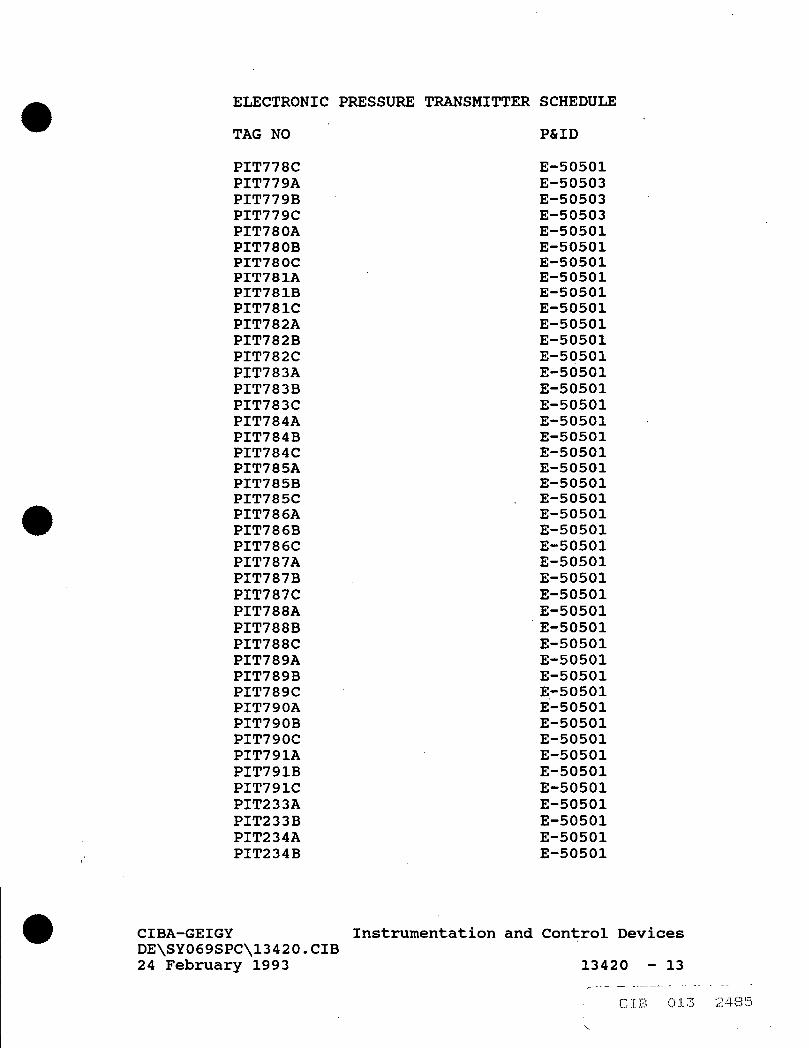
ELECTRONIC PRESSURE
TAG NO
PIT778C PIT779A PIT779B PIT779C PIT780A PIT780B PIT780C PIT781A PIT781B PIT781C PIT782A PIT782B PIT782C PIT783A PIT783B PIT783C PIT784A PIT784B PIT784C PIT785A PIT785B PIT785C PIT786A PIT786B PIT786C PIT787A PIT787B PIT787C PIT788A PIT788B PIT788C PIT789A PIT789B PIT789C PIT790A PIT790B PIT790C PIT791A PIT791B PIT791C PIT233A PIT233B PIT234A PIT234B
TRANSMITTER SCHEDULE
P&ID
E-50501 E-50503 E-50503 E-50503 E-50501 E-50501 E-50501 E-50501 E-50501 E-50501 E-50501 E-50501 E-50501 E-50501 E-50501 E-50501 E-50501 E-50501 E-50501 E-50501 E-50501 E-50501 E-50501 E-50501 E-50501 E-50501 E-50501 E-50501 E-50501 E-50501 E-50501 E-50501 E-50501 E-50501 E-50501 E-50501 E-50501 E-50501 E-50501 E-50501 E-50501 E-50501 E-50501 E-50501
CIBA-GEIGY Instrumentation and Control Devices DE\SY069SPC\13420.CIB 24 February 1993 13420 - 13
CIB 013 248!

ELECTRONIC PRESSURE TRANSMITTER SCHEDULE
TAG NO P&ID
PIT22 E-50501 PIT24 E-50501 PIT27 E-50501 PIT28 E-50501 PIT236A E-50501 PIT236B E-50501 PIT237A E-50501 PIT237B E-50501 PIT137 E-50501
CIBA-GEIGY Instrumentation and Control Devices DE\SY069SPC\13420.CIB 24 February 1993 13420 - 14

TEMPERATURE TRANSMITTER SCHEDULE
TAG NO P&ID
TIT2 E-50503 TIT3 E-50503 TIT4 E-50503
CIBA-GEIGY Instrumentation and Control Devices DE\SY069SPC\13420.CIB 24 February 1993 13420 - 15

MAGNETIC FLOW METER SCHEDULE
METER FLOW SIZE RANGE
TAG NO. (INCHES) (GPM) P&ID
FIT100 8 0-3000 E50503 FIT663 1.5 0-90 E50502 FIT664 1.5 0-70 E50502 FIT666 1 0-60 E50502 FIT667 1 0-50 E50502 FIT668 1 0-40 E50502 FIT670 1 0-60 E50502 FIT671 1 0-40 E50502 FIT673 1 0-50 E50502 FIT674 0.5 0-20 E50502 FIT746 1.5 0-70 E50501 FIT747 1 0-60 E50501 FIT748 1 0-60 E50501 FIT749 1 0-60 E50501 FIT750 1.5 0-60 E50501 FIT754 1 0-50 E50502 FIT755 1 0-60 E50502 FIT761 1.5 0-90 E50503 FIT762 1.5 0-70 E50503 FIT763 1 0-40 E50502 FIT764 1 0-40 E50502 FIT765 2 0-130 E50503 FIT766 1 0-40 E50502 FIT767 1 0-40 E50502 FIT768 0.5 0-30 E50502 FIT769 1.5 0-90 E50503 FIT770 1 0-50 E50502 FIT771 1 0-40 E50502 FIT772 2 0-130 E50503 FIT773 1 0-50 E50502 FIT774 1 0-40 E50502 FIT775 1 0-40 E50502 FIT776 2 0-120 E50502 FIT777 1 0-50 E50502 FIT778 1 0-50 E50501 FIT779 1.5 0-100 E50503 FIT780 1.5 0-70 E50501 FIT781 1 0-50 E50501 FIT782 1.5 0-80 E50501 FIT783 1.5 0-70 E50501 FIT784 1 0-60 E50501 FIT785 1 0-50 E50501 FIT786 1.5 0-120 E50501 FIT787 1.5 0-70 E50501
CIBA-GEIGY Instrumentation and Control Devices DE\SY069SPC\13420.CIB 24 February 1993 13420 - 16

MAGNETIC FLOW METER SCHEDULE
TAG NO.
METER SIZE
(INCHES)
FIT788 FIT789 FIT790 FIT791 FIT233 FIT234 FIT236 FIT237 FIT137
1.5 1.5 1.5
2 1.0 1.5 2.5 .75 .5
FLOW RANGE (GPM) P&ID
0-70 0-90 0-120 0-140 30-45 70-105 161-242 15-23 10-15
E50501 E50501 E50501 E50501 E50501 E50501 E50501 E50501 E50501
CIBA-GEIGY Instrumentation and Control Devices DE\SY069SPC\13420.CIB 24 February 1993 13420 - 17
CIB 013 2489

SINGLE POINT LEVEL SWITCH SCHEDULE
TAG NO.
LSH233 LSH234 LSH236 LSH237 LSH22 LSH24 LSH27 LSH28
P&ID
E50501 E50501 E50501 E50501 E50501 E50501 E50501 E50501
CIBA-GEIGY Instrumentation and Control Devices DE\SY069SPC\13420.CIB 24 February 1993 13420 - 18
/• : CIB 013 2490

CONTROL VALVE SCHEDULE
VALVE FLOW FLOW MAX SIZE NORM MAX FLOW
TAG NO. INCHES (GPM) (GPM) CV
FCV663 3 48 72 19.2 FCV664 3 35 52.5 9.7 FCV666 2 33 49.5 18.9 FCV667 3 22 33 10.9 FCV668 2 16 24 3.7 FCV670 3 32 48 14.1 FCV671 2 16 24 4.3 FCV673 2 25 37.5 6.4 FCV674 1 10 15 2.8 FCV746 3 42 63 13.2 FCV747 3 31 46.5 15.7 FCV748 2 32 48 8.9 FCV749 3 32 48 9.5 FCV750 3 34 51 11.9 FCV754 2 26 39 13.7 FCV755 2 28 42 11.2 FCV761 3 50 75 23.7 FCV762 3 39 58.5 43.4 FCV763 2 18 27 5.2 FCV764 1 18 27 3.4 FCV765 3 74 111 27.2 FCV766 2 21 31.5 9.0 FCV767 2 17 25.5 7.0 FCV768 2 13 19.5 6.1 FCV769 3 51 76.5 15.4 FCV770 3 25 37.5 7.1 FCV771 2 18 27 15.7 FCV772 3 73 109.5 31.1 FCV773 2 27 40.5 7.6 FCV774 2 18 27 8.4 FCV775 2 17 25.5 19.2 FCV776 2 68 102 20.5 FCV777 2 22 33 5.2 FCV778 2 24 36 7.1 FCV779 3 60 90 39.6 FCV780 3 37 55.5 20.0 FCV781 2 27 40.5 11.6 FCV782 3 43 64.5 13.7 FCV783 3 34 51 15.2 FCV784 2 29 43.5 15.4 FCV785 2 22 33 21.0 FCV786 2 68 102 24.2 FCV787 3 39 58.5 21.2 FCV788 3 34 51 13.5
NORM FLOW DIFF (PSIG) P&ID
80. 1 E50502 112. 6 E50502 74. 7 E50502 85. 3 E50502
113. 7 E50502 78. 3 E50502 73. 0 E50502 86. 0 E50502 60. 6 E50502 54. 8 E50501 46. 6 E50501 76. 2 E50501 78. 7 E50501 76. 1 E50501 48. 7 E50502 53. 8 E50502 89. 3 E50503 66. 0 E50503 94. 3 E50502
141. 7 E50502 66. 0 E50503 85. 4 E50502 25. 5 E50502 72. 9 E50502 56. 0 E50503 88. 3 E50502 60. 8 E50502 71. 9 E50503 85. 3 E50502 56. 6 E50502 67. 9 E50502 55. 0 E50502
130. 2 E50502 84. 6 E50501 25. 0 E50503 38. 9 E50501 48. 2 E50501 51. 4 E50501 44. 8 E50501 45. 7 E50501 58. 6 E50501 75. 9 E50501 49. 0 E50501 75. 5 E50501
CIBA-GEIGY Instrumentation and Control Devices DE\SY069SPC\13420.CIB 24 February 1993 13420 - 19

CONTROL VALVE SCHEDULE
VALVE FLOW FLOW MAX NORM FLOW SIZE NORM MAX FLOW DIFF
TAG NO. INCHES (GPM) (GPM) CV (PSIG) P&ID
FCV789 FCV790 FCV791 FCV233 FCV234 FCV236 FCV237 FCV137
3 3 3 2 3 4 2 1
48 65 84 30 70 161 15 10
72 97.5 126 45 105 242 23 15
29, 24, 33,
8, 9,
13.8 18.2
76.9 76.1 68.1 71.0 63.9 79.4 110.9
E50501 E50501 E50501 E50501 E50501 E50501 E50501 E50501
CIBA-GEIGY Instrumentation and Control Devices DE\SY069SPC\13420.CIB 24 February 1993 13420 - 20

PRESSURE GAUGE SCHEDULE
TAG NO P&ID
PI2A E50501 PI2B E50501
CIBA-GEIGY Instrumentation and Control Devices DE\SY069SPC\13420.CIB 24 February 1993 13420 - 21

LEAK LOCATION/DETECTION UNIT SCHEDULE
TAG NO P&ID
LA1000 E50501
END OF SECTION
CIBA-GEIGY Instrumentation and Control Devices DE\SY069SPC\13420.CIB 24 February 1993 13420 - 22

SECTION 13451
CONTROL COMPUTER AND REMOTE OPERATIONS CONTROLLER SYSTEM
PART 1 GENERAL
1.01 SECTION INCLUDES
A. Remote Operations Controllers (ROCs).
B. Input/output (I/O) hardware.
C. Distributed control system (DCS) hardware.
D. Fiber optic network communications devices.
1.02 PRODUCTS INSTALLED BUT NOT FURNISHED UNDER THIS SECTION
A. Digital Equipment Corporation (DEC) model VAX station 3100 workstation.
1.03 RELATED SECTIONS
A. Section 13410: General Instrumentation, Control, and Monitoring.
B. Section 13415: Description of Operation.
C. Section 13420: Instrumentation and Control.
D. Section 13440: Well Control Panels.
E. Section 13460: Control System Software.
1.04 REFERENCES
A. ANSI - American National Standards Institute:
B. IEEE - Institute of E l e c t r i c a l and Electronics Engineers:
C. ISA - Instrument Society of America:
D. NEMA - National E l e c t r i c a l Manufacturers Association:
E. NFPA - National Fire Protection Association:
CIBA-GEIGY Control Computer And Remote \13451.CIB Operations Controller System 24 February 1993 13451 - 1

1.05
A.
B.
C.
1.06
A.
1.07
A.
B.
C.
D.
1.08
A.
1.09
A.
B.
C.
DEFINITIONS
DCS: Distributed control system.
PID: Proportional-Integral-Derivative.
ROC: Remote Operations Controller.
SYSTEM DESCRIPTION
Design Requirements: 1. Assure component compatibility. 2. Provide accessories and appurtenances required
for proper operation. 3. Coordinate equipment operation with equipment
provided under other Sections. 4. Refer to Section 13440 for enclosure and
associated equipment specifications.
SUBMITTALS
Provide according to requirements of Section 01300.
Provide Shop Drawings, Operating and Maintenance Manuals, and Record Drawings according to requirements of Section 13410.
Provide name, address, and telephone number of the nearest factory authorized repair f a c i l i t y for each component and device provided by either manufacturer or model name/number.
Provide testing procedures and results in hard copy for approval.
QUALITY CONTROL
Notify the Engineer and the Owner in writing at least 14 days prior to the proposed date for commencing tests.
DELIVERY, STORAGE, AND HANDLING
Ship products to site by dedicated air-cushioned van or approved equal according to manufacturer's recommendations.
Box, crate, or otherwise protect products.
Protect finished surfaces. Repair damage in approved manner.
CIBA-GEIGY \13451.CIB 24 February 1993
Control Computer And Remote Operations Controller System
13451 - 2

D.
E.
F.
1.10
A.
B.
C.
D.
E.
F.
1.11
A.
Protect products from water, moisture, and humidity.
Protect electronic and integrated c i r c u i t devices from sta t i c e l e c t r i c i t y and magnetic fields, and maintain manufacturer's recommended temperature and humidity.
Return returnable containers and special shipping devices.
WARRANTY
Warranty period and correction period for products and the system as a whole shall begin at Substantial Completion.
Provide f i e l d services by the system supplier for correction of defects.
Repairs made during the correction period shall extend the original correction period for an additional year from the date of repair.
The system supplier w i l l be given an opportunity to confirm the existence of the defect but shall not delay correction while making such determination.
I f within 10 days after Owner has notified Contractor of defective Work, corrective action has not been started, Owner may correct or have the defective Work corrected, and charge the Contractor for the cost.
In the event of any emergency where, in the judgement of the Owner, delay would cause serious loss or damage, repairs or adjustments may be made by the Owner or a third party chosen by the Owner with advance notice to Contractor and the cost of the work shall be paid by Contractor.
MAINTENANCE
Provide under the requirements of Section 13410.
CIBA-GEIGY \13451.CIB 24 February 1993
Control Computer And Remote Operations Controller System
13451 - 3

PART 2 PRODUCTS
2.01 MANUFACTURERS
A. Do not substitute products li s t e d in this Section by manufacturer and model number.
B. Remote Operations Controller System: Fisher Controls Marshalltown, Iowa 50158
C. Distributed Control System: Fisher Controls International, Inc. 8301 Cameron Road Austin, Texas 78753
D. Power Protection Systems: Control Concepts 328 Water Street Binghamton, New York 13902 or equal
E. Loop Power Supply: Moore Industries 16650 Schoenborn Street Sepulveda, California 91343 or equal
F. Fiber Optic Modem Devices: 3M Telecom Systems Group 6801 River Place Blvd. Austin, Texas 78726 or equal
G. Engineering Workstations: Digital Equipment Corporation 146 Main Street Maynard, Massachusetts 01754
2.02. AUTOMATION REQUIREMENTS
A. Implement PID loop control of water flow from each of fifty-one extraction wells to maintain required pumping rate at each well location.
B. Monitor and control: analog inputs, analog outputs, digital inputs, and digital outputs.
C. Provide supervisory control of the groundwater extraction system through the existing Waste Treatment Plant Fisher PROVOX Distributed Control System. Implement the following functions:
CIBA-GEIGY \13451.CIB 24 February 1993
Control Computer And Remote Operations Controller System
13451 - 4

E.
F.
2.03
A.
1. Communications between the Fisher PROVOX DCS and the f i e l d Remote Operations Controllers.
2. Control of operating mode - auto, manual. 3. Control of each well pump motor - on, off. 4. Entry of well flow rate setpoints and PID
parameters. 5. Entry of alarm setpoints.
Measure continuously and display at the Waste Treatment Plant Fisher PROVOX DCS: 1. Flow rate in each well pump discharge line. 2. Pressure at the well pump discharge. 3. Pressure after the well control valve. 4. Control valve position. 5. Pressure at the point where the well pump
discharge line t i e s into the pipe manifold where shown on the drawings.
6. Temperature at each of the three points where the manifold systems t i e into the 14 inch header.
Monitor continuously and display at the Waste Treatment Plant Fisher PROVOX DCS: 1. System alarms. 2. Status of each of the system leak detection
devices. 3. Status of a l l system heat tracing thermostats.
Provide process data analysis, historian and reporting capabilities through the existing Waste Treatment Plant control room Hewlett-Packard HP9000/835 computer.
SYSTEM CONFIGURATION
ON-SITE SINGLE AND DOUBLE WELL REMOTE OPERATIONS CONTROLLERS 1. A Fisher Controls Type ROC364 Remote Operations
Controller (ROC) shall be installed in each Well Control Panel to control the water flow and monitor operation of each well or in the case of double wells, both wells. The ROCs shall be configured with a single sixteen position Input/Output (I/O) module rack for a single well or two sixteen position module racks for a double well. Any combination of discrete or analog I/O can be accomodated on each module rack.
2. Each ROC processor and i t s associated module rack(s) shall be mounted on a Fisher provided Backplate which in turn shall be mounted in the Well Control Panel. Power for the ROC shall be supplied by a Moore Industries Model DPS-1200, 24VDC 1.2 AMP power supply.
CIBA-GEIGY \13451.CIB 24 February 1993
Control Computer And Remote Operations Controller System
13451 - 5

3. Each ROC shall be interfaced to one of three zone fiber optic Local Area Network (LAN) channels through a 3M Series 6000 Modular Fiber Optic Modem. Each fiber optic LAN channel shall communicate to the Fisher PROVOX DCS Data Highway in the Waste Treatment Plant control room through a corresponding 3M Modular Fiber Optic Modem and a Fisher PROVOX External Interface Card. Communication protocol between the External Interface Card and the ROC shall be provided by Fisher and embedded in the External Interface Card operating software.
4. Loop power for the pressure sensor two wire transmitters at each well shall be provided through the ROC I/O Module Rack.
5. El e c t r i c power to the ROC power supply, flow transmitter, flow control valve operator, and the optical modem shall be provided through a 1 KVA, 120 VAC isolation and line conditioning transformer. Incoming line power to the primary of the transformer shall be connected through an internally mounted single pole disconnect switch and 10 amp fuse.
6. Controller wiring shall be type MTW rated 90 DEG C, 600 volts minimum, unless otherwise noted on drawings and color coded according to function. The following color code shall be used: COLOR ABBREVIATION DESCRIPTION Black BK Line voltage circ u i t s
(Hot) White WH Line voltage ci r c u i t s
(Neutral) Red RD AC control c i r c u i t s Yellow YL Line voltage ci r c u i t s
(Hot) originating external to panel
Green GN Ground
Two conductor shielded cable shall be color coded black (+) and white (-).
7. A l l f i e l d input/output connections, with the exception of the fiber optic cables, to the ROC shall terminate on compression clamp type terminal blocks located on the ROC Module Rack. Low voltage signal connections (24 volts or less) and high voltage connections shall be separated to the greatest extent possible, preferably on opposite sides of the enclosure. Wiring shall be run in plastic wiring ducts with covers.
CIBA-GEIGY Control Computer And Remote \13451.CIB Operations Controller System 24 February 1993 13451 - 6

Wire size shall be #16 AWG stranded copper for control and #12 AWG stranded copper for power buses. Analog signal input/output wiring shall be two conductor shielded #18 AWG. Wiring shall be labeled with the wiring identification shown on schematics and e l e c t r i c a l drawings. Wire labels shall be the nonmetallic sleeve type with machine printed identification. Ground continuity between the Well Control Panel enclosure and the ROC sub-panel shall be provided. A l l grounding conductors shall be green insulated stranded copper. A l l grounds shall be tied to a central location and not "daisy-chained" together. Where the grounding conductor i s attached to a painted surface, the paint shall be removed in the area of the connection. Star type washers shall be used on a l l bolted ground connections.
B. ZONE 2 OFF-SITE SINGLE AND DOUBLE WELL REMOTE OPERATIONS CONTROLLERS 1. A Fisher Controls Type ROC364 Remote Operations
Controller (ROC) shall be installed in Manways #3, #5, and #6. The ROCs shall control the water flow and monitor the operation of the wells as follows: Manway #3, Wells 137 and 237; Manway #5, Well 233 and the flow control valve for Well 236; Manway #6, Well 234. The ROCs shall be configured with a single sixteen position Input/Output (I/O) module rack for a single well or two sixteen position module racks for a double well. Any combination of discrete or analog I/O can be accomodated on each module rack.
2. Each ROC processor and i t s associated module rack(s) shall be mounted on a Fisher provided Backplate which in turn shall be mounted in a NEMA 4, 12-gauge steel enclosure, 36"H x 30"W x 10"D. Power for the ROC shall be supplied by a Moore Industries Model DPS-1200, 24VDC 1.2 Amp power supply.
3. Each ROC shall be interfaced to the Zone 2 fiber optic Local Area Network (LAN) channel through a 3M Series 6000 Modular Fiber Optic Modem. The fiber optic LAN channel shall communicate to the Fisher PROVOX DCS Data Highway in the Waste Treatment Plant control room through a corresponding 3M Modular Fiber Optic Modem and a Fisher PROVOX External Interface Card. Communication protocol between the External Interface Card and the ROC shall be provided by Fisher and embedded in the External Interface Card operating software.
4. Loop power for the pressure sensor transmitters shall be the same as described under on-site ROC systems.
9.
10.
CIBA-GEIGY Control Computer And Remote \13451.CIB Operations Controller System 24 February 1993 13451 - 7
CIB 014 000.1

5. E l e c t r i c power to the controller panel, heat tracing, and the manway 120 VAC duplex receptacle shall be provided through a 5 KVA, 480/240/120 VAC mini-power center located separately in the manway. Power for the flow transmitter, flow control valve operator, and the sump level switch shall be provided from the controller panel through individually fused ci r c u i t s .
6. Panel wiring descriptions and color coding shall be the same as described under on-site ROC systems.
7. Grounding for both the PLC and PLC I/O Control Panel systems shall be the same as described under on-site ROC systems.
C. INSTRUMENT PANEL MANWAY #1 1. A Fisher Controls Type ROC312 Remote Operations
Controller (ROC) shall be installed in Manway #1. The ROC shall monitor the operation of Well 236 and communicate over a serparate fiber optic link to the ROC in Manway #5 which shall control the flow control valve associated with Well 236. The ROC312 contains twelve integral I/O connections, six fixed and six modular.
2. Additional specifications are the same as described under Zone 2 off-site ROC systems.
C. INSTRUMENT PANELS MANWAYS #2, 4, 7, & 8 1. A Fisher Controls Type ROC312 Remote Operations
Controller (ROC) shall be installed in Manways #2, #4, #7 and #8. Each ROC shall monitor the status of the manway sump level switch and heat tracing.
2. Additional specifications are the same as described under Zone 2 off-site ROC systems.
D. INSTRUMENT PANEL ZONE 2 1. A Fisher Controls Type ROC364 Remote Operations
Controller (ROC) shall be installed in Zone 2 Instrument Panel. The ROC shall control the status of the pump starters for Wells 137, 233, 234, 237 and 236. The ROC shall be configured with a single sixteen position Input/Output (I/O) module rack.
2. E l e c t r i c power to the Instrument Panel shall be provided from the Zone 2 mini-power center located near but separate from the Instrument Panel.
3. Additional specifications are the same as described under Zone 2 off-site ROC systems.
E. FISHER PROVOX DISTRIBUTED CONTROL SYSTEM BUILDING 743 1. Two new Type DC6412 Operator Console Bay Units with
video display and keyboard shall be provided in the Bldg. 743 Control Room dedicated solely to the groundwater extraction operation. The two existing Console Electronics Units (CEU) shall be upgraded
CIBA-GEIGY Control Computer And Remote \13451.CIB Operations Controller System 24 February 1993 13451 - 8
CIB 014 0002

2.04
A.
B.
C.
with Type DC6463-UPG3-MEM3 Console Electronics Upgrade Kits to 2000 point MicroVAX RT systems with a 71M byte hard disk. The two existing DC6412 Console Bay Units shall be controlled by one CEU and the new consoles by the second CEU. Also installed in the second CEU shall be a new Type DC6463-UPG37 Video Display Controller module.
2. A new Digital Equipment Company VAX station 3100 Engineering Workstation shall be installed to develop and download the system configuration. A Type DH6021-1-COMM2 Network Interface Unit (NIU) shall be provided in a Console Bay to interface the workstation to the PROVOX Data Highway.
3. Four Type CL6921 External Interface Cards programmed with the ROC Protocol shall be installed in the Unit Operations Controller. These cards shall be connected to four 3M fiber optic modems to establish communications links to the ROC systems.
COMPONENTS
Fisher Controls Type ROC364 Remote Operations Controller (ROC). The controller i s used for applications requiring flow computation, PID control and logic/sequencing control especially at remote locations. The ROC consists of a Master Controller Unit (MCU) featuring an NEC V25+ microprocessor and 128K-Byte on-board battery-backed random access memory (RAM). Configuration parameters are stored in 32K-Byte of electrically-eraseable read-only memory(EEPROM). A plug-in ROCPAC (ROM) contains the operating system and applications firmware.
Fisher Controls Type ROC364 128K RAM Expansion Module. The RAM Expansion Module increases memory in 128K-Byte increments. The number of expansion modules required depends primarily on the number of database points to be archived. Up to two modules may be installed.
Fisher Controls Type ROC364 RS-422/RS-485 Asychronous Communication Card. The Communication Card provides an additional port for communicating to the ROC. Up to two cards may be installed.
Fisher Controls Type ROC364 16-socket Module Rack. The Module Rack provides sockets for up to 16 I/O modules of any combination of discrete inputs, discrete outputs, analog inputs, analog outputs, or
CIBA-GEIGY \13451.CIB 24 February 1993
Control Computer And Remote Operations Controller System
13451 - 9
CIB 014 0003

F.
G.
H.
I .
J .
K.
pulse inputs. Up to four Module Racks for a t o t a l of 64 points can be used with one MCU. F i e l d wiring connects to plug-in terminal blocks mounted below the module sockets.
Fisher Controls Type ROC364 Backplate. The Backplate provides a mounting panel for the MCU and Module Racks.
Fisher Controls ROC300-Series Analog Input Loop Module (AI LOOP). The Analog Input Loop Module i s used to monitor a current loop. The loop module provides a source voltage for powering current.loop devices.
Fisher Controls ROC300-Series Analog Input D i f f e r e n t i a l Module (AI DIFF). The Analog Input D i f f e r e n t i a l Module i s used to monitor a current loop or voltage from externally powered devices and i s isloated from the ROC power supplies.
Fisher Controls ROC300-Series Analog Output Source Module (AO SRC). The Analog Output Source Module provides a current and a voltage output for powering analog devices.
Fisher Controls ROC300-Series Discrete Input Source Module (DI SRC). The Discrete Input Source Module monitors the staus of relays, s o l i d - s t a t e switches, or other two state devices. The source module provides a source voltage for dry relay contacts or for an open-collector s o l i d - s t a t e switch.
Fisher Controls ROC300-Series Discrete Output Relay Module (DO RLY). The Discrete Output Relay Module provides a set of single-pole-double-throw dry relay contacts for switching a powered load.
Fisher Controls Type ROC312 Single Board Controller. The ROC312 Single Board Controller provides the central monitoring, control, acquisition, communications, and data archival for a l l low end ROC s e r i e s applications. I t contains s i x fixed I/O plus expansion for s i x points of modular I/O. The ROC312 consists of a Master Controller Unit (MCU) featuring an NEC V25+ microprocessor and 128K-Byte on-board battery-backed random access memory (RAM). Configuration parameters are stored i n 8K-Byte of e l e c t r i c a l l y - e r a s e a b l e read-only memory(EEPROM). A
CIBA-GEIGY \13451.CIB 24 February 1993
Control Computer And Remote Operations Controller System
13451 - 10
CIB 014 .00C

plug-in ROCPAC (ROM) contains the operating system and applications firmware.
L. Control Concepts I s l a t r o l Plus Model IC+115 Power F i l t e r . The I s l a t r o l Plus continuously tracks the entire power sine wave and reponds instantaneously to AC line disturbances assuring the constant level of attenuation required to fully clean up both catastrophic high energy events and low voltage deviations.
M. Moore Industries DPS 1200 DIN Power Supply. The Moore Industries DPS 1200 DIN power supply provides a 24 Vdc output voltage at up to 1.2 Amps. The supply i s designed with continuous short c i r c u i t and short term (< 15 seconds) overload protection. In addition, i t offers input/output isolation, convection cooling, a derated c i r c u i t design for added dependability and i s enclosed in a rail-mounted DIN housing.
N. 3M Series 6000 Modular Fiber Optic Modem. The Series 6000 i s a fiber optic interface modem designed in a modular format. The modular modem consists of four basic components: the rack; ele c t r i c a l interface card; optical interface card; and power supply.
0. 3M Series 6000 Type 6A02 Modular Rack. The 6A02 Modular Rack i s the base platform for a l l Series 6000 Modular Modems. The rack holds one power supply module, one master ele c t r i c a l interface module and has four additional slots for any combination of elec t r i c a l and optical interface modules.
P. 3M Series 6000 Type 6A01 Power Supply. The Type 6A01 Power Supply i n s t a l l s in the Modular Rack to supply operating power. Output i s +10 VDC +.5 AMP and -10 VDC -1.5 AMP unregulated.
Q. 3M Series 6000 Type 6E01 Optical Interface Module. The Type 6E01 Optical Interface Module interfaces 850 nm optical signals for distances up to 10,000 feet.
R. 3M Series 6000 Type 6C10 RS-232/422 Compatible El e c t r i c a l Interface Module. The Type 6C10 RS-232/422 Compatible E l e c t r i c a l Interface Module conditions the RS-232/422 el e c t r i c a l signals supplied to and from the network equipment for transmission over the fiber optic network.
CIBA-GEIGY Control Computer And Remote \13451.CIB Operations Controller System 24 February 1993 13451 - 11
' CIB 014 0

S. Fisher Controls International, Inc. Type.DC6463, Series PROVOX Console Electronic Units. The DC6463 Console Electronic Unit i s the heart of PROVOX consoles. PROVOX consoles provide monitoring, and operations for continuous and batch processes. To be operational, each console must include at least one console bay unit with keyboard and video display unit (VDU) one console disk unit, and one console logging unit. Each console electronics unit can support a maximum of: 1. Three DC6400 Series Console Bay Units in any
combination. These include the Types DC6412, DC6413, DC6414, and DC6415 bay units.
2. Two Type DC6481 Console Logging Units for alarm messages, reports, and so on.
3. One type DC6471 Console Disk Unit (Flexible). 4. One Type DC6486 Console Printer Unit for hard
copies of VDU displays. A PROFLEX configuration device transfers configuration data over the data highway into console memory. I f the optional hard disk i s available, i t also receives configuration data from the PROFLEX device.
T. Fisher Controls International, Inc. PROVOX Console Bay Unit, Type 64IX. The Type DC641X Console Bay Unit i s a modular cabinet that houses the video display unit (VDU's), operations keyboards, and console electronics units. This console bay unit, when used singly or in combination, i s the basis for PROVOX consoles. The lower part of each console bay provides 2 sets of standard EIA 19-inch r a i l s for equipment mounting. The front r a i l s can be reached through a removable front panel. A lock-able rear door provides access to the rear r a i l s . The top portion of the console bay includes a work surface, a keyboard, and a VDU with a VDU controller. The optional f u l l stroke keyboard shall be provided. The 115 Vdc, 60 hz. model shall be provided.
U. Fisher Controls International, Inc. Network Interface Unit, Type DH6021. The Type DH6021 Network Interface Unit receives and transmits information between PROVOX devices on a data highway and the Computer Highway Interface Package (CHIP) running on an attached computer system. Typical information exchange between CHIP and PROVOX via the NIU includes access and change of operating parameters (process variables, set points, valve outputs, control modes, and alarms) and tuning parameters (controller gain, reset, and rate). This
CIBA-GEIGY \13451.CIB 24 February 1993
Control Computer And Remote Operations Controller System
13451 - 12

capability provides the computer system with information required for plant-wide monitoring, supervision and process optimization. The NIU uses an IEEE 802.3/Ethernet local area network and DECnet communications protocol. The 115 Vdc, 60 hz. model shall be provided.
V. Fisher Controls International, Inc. External Interface Card, Type DH6021. The Type CL6921 External Interface Card (EIC) i s a micro-processor-based interface card providing communication between non-PROVOX fi e l d devices and a 20-series control unit. The card communicates with the control unit via a s e r i a l I/O bus and f i e l d devices via the RS-232C or current loop s e r i a l ports. The external interface card i s available with application firmware. This EIC shall be provided with AEG Modicon firmware. The EIC i s installed in any of 14 slots in the Type CP6701 Control I/O Card F i l e . The coaxial cable connecting the 20-Series controller to the control I/O card f i l e can be as long as 5000 feet, allowing the customer to position the card f i l e and external interface card outside the control room and closer to the f i e l d devices.
W. Digital Equipment Corporation (DEC) Model VAX station 3100 Workstation. 1. This workstation with a l l the l i s t e d accessories
and options has already been ordered and received. The Contractor i s not responsible for supplying this item.
2. The DEC VAX 3100 Model 40 Workstation i s a standalone computer to be used as the Distributed Control System's (DCS) engineer workstation. The workstation i s a node on the Fisher data highway. The engineers workstation i s used to configure and re-program the DCS, then download changes made to the various devices on the DCS data highway. This workstation shall consist of the following:
3. Single plane system. 4. Mouse. 5. Thin wire/thick wire Ethernet ports with a T-
connector and 2 terminators (thin wire) and an Ethernet loopback connector (thick wire).
6. 3 foot convenience power cord (monitor to system box) .
7. VMS base license, including DECWindows, VAXcluster, DECnet VAX, and VWS.
8. English language user documentation. 9. Operating system base license. 10. SCSI disk controller drive plate.
CIBA-GEIGY Control Computer And Remote \13451.CIB Operations Controller System 24 February 1993 13451 - 13
1 C I B 014 000
11. 16 Mbytes of memory. 12. Power cord; US, 120V, order number BN19P-1K. 13. Graphics option; 8-plane graphics, factory
installed, including 3 foot color video cable, order number VS4OX-PC.
14. Color Monitor; 19 inch, order number VR299-DA. 15. Keyboard; English, regular type, order number LK201-
RE. 16. Internal mass storage; Disk drive, 104 Mbyte,
factory installed, order number RZ23-EG. 17. Internal mass storage; Compact disc drive, 600
Mbyte, factory installed, order number RRD40-EG. 18. Internal mass storage; Streaming tape drive, 95
Mbyte, factory installed, order number TZ30-EG. 19. Software media; VMS single-user k i t and DECwindows,
on compact disk, order number QA-09SAA-H8. 20. External mass storage; 332 Mbyte hard disk in BA40
single drive expansion box, 120 V, with power cord, order number RZ55-FA.
21. Printer; Wide carriage, dot matrix, near letter quality (NLQ), draft and graphics printing, tractor and friction feed, 240 characters per second (CPS) draft, 40 CPS NLQ, 120 V, order number LA210-AA.
X. Miscellaneous Enclosure Components including wiring, terminal boards, heaters, fans, vents, thermostats, and other enclosure related components shall be provided as shown on the Drawings and/or B i l l s of Materials. Component specifications for miscellaneous items shall be found in Section 13440.
2.05 SOURCE QUALITY CONTROL
A. Perform a system test on each sub-system control panel and other device at manufacturer's f a c i l i t y prior to shipment.
B. Testing shall verify operation of both hardware and software.
C. Document proposed test procedure and provide for approval. Receive approval prior to testing.
D. Simulate normal operating sequences and fault conditions in test.
E. Test duration; 48 hours without faults.
F. Hardware Test: 1. Test ROC hardware associated or interfaced to DCS
equipment at one location.
CIBA-GEIGY Control Computer And Remote \13451.CIB Operations Controller System 24 February 1993 13451 - 14
CIB 0.1.4 0008

PART 3
3.01
A.
3.02
A.
B.
C.
D.
E.
2. Include i n t e s t setup simulated analog and discrete inputs from various portions of the process.
3. Demonstrate correct performance of each peripheral.
4. Test DCS equipment by manufacturer prior to shipment.
Software Test: 1. Include i n software t e s t s running of each
operational program, diagnostics, debugging routine, and system t e s t routine.
2. F u l l y t e s t operating system, advanced process control language compiler, and associated drivers prior to system t e s t .
3. No software "patches" or changes w i l l be allowed to bypass f a i l e d or flawed modules during the t e s t .
EXECUTION
INSTALLATION
I n s t a l l products as shown on Drawings, and according to manufacturer's recommendations and applicable codes.
FIELD QUALITY CONTROL
Perform f i e l d acceptance t e s t a f t e r i n s t a l l a t i o n of system and checkout by Contractor.
Test format: Cause and eff e c t . I n i t i a t e an input (cause) to the system and upon the system producing an anticipated r e s u l t ( e f f e c t ) , the s p e c i f i c t e s t requirement w i l l be considered s a t i s f i e d .
F i e l d acceptance t e s t s h a l l consist of repeating source quality control testing addition to tes t i n g the system under specified process conditions, including: 1. Each operational mode. 2. Taking process variables to t h e i r l i m i t s to
v e r i f y alarm functioning. 3. Interlock v e r i f i c a t i o n .
Test duration; 14 days of continuous running without los s of basic functions.
F a i l u r e of redundant equipment s h a l l not be considered as downtime provided automatic f a i l over
CIBA-GEIGY \13451.CIB 24 February 1993
Control Computer And Remote Operations Controller System
13451 - 15
CIB 014 0009

occurs and, i n the opinion of Engineer, f a i l u r e was not caused by deficiency i n design or i n s t a l l a t i o n .
F. Terminate testing and r e s t a r t entire t e s t on repeated f a i l u r e of any component.
G. Forms for documentation for the F i e l d Acceptance Test s h a l l include: 1. For those functions that can be demonstrated on a
loop-by-loop basis: a. Project name. b. Loop number. c. Loop description. d. Test procedure description. e. For each component:
1) Tag number. 2) Description. 3) Manufacturer. 4) Data sheet number.
f. Sign-off and date by system supplier and Owner.
2. For those functions that cannot be demonstrated on a loop-by-loop basis, l i s t s p e c i f i c t e s t s conducted including: a. Description of function demonstrated. b. Sign-off and date by system supplier and
Owner.
3.03 DEMONSTRATION
A. Provide services of technical representative as necessary to ca l i b r a t e , t e s t , and advise others of procedures for adjustment and operation.
B. Provide not l e s s than 30 working days of system startup assistance by engineering and programming personnel.
C. Provide necessary t e s t equipment.
D. Conduct train i n g courses for personnel selected by the Owner.
E. Provide tra i n i n g at three l e v e l s : maintenance, plant operator and programmer, and management.
F. Conducted training by personnel fa m i l i a r with the system supplied and with experience i n implementing in s t r u c t i o n a l courses.
END OF SECTION
CIBA-GEIGY \13451.CIB 24 February 1993
Control Computer And Remote Operations Controller System
13451 - 16
CIB 014 001

SECTION 13460
CONTROL SYSTEM SOFTWARE
PART 1 GENERAL
1.01 SUMMARY
A. General 1. This section specifically describes the
manufacturer provided and custom developed software for the Control Computer and Remote Operations Controller System. I t i s the intent of this Section to also supplement where applicable, other Sections of Division 13, and therefore information described in this section may amplify, modify, or supersede, as the case may be, other Sections of this Division. I f a conflict should appear, the Contractor shall s o l i c i t the Engineer for written c l a r i f i c a t i o n .
2. I t i s the intent to describe the software requirements of each main system so that the Contractor i s aware of the magnitude of the total Control Computer and Remote Operations Controller System and to ensure compatibility with systems already existing.
B. Scope of Work The Contractor shall provide the software described herein, complete in every detail, and include validation, start-up, and operational testing of a complete and operable Control Computer and Remote Operations Controller System as shown on the plans and as specified in Division 13.
C. Related Sections
1. Section 13450:
2. Section 13410:
3. Section 13415: 4. Section 13420: 5. Section 13440:
Control Computer and Remote Operations Controller System General Instrumentation, Control, and Monitoring Description of Operation Instrumentation and Control Well Control Panels
1.02 SUBMITTALS
A. Provide submittals according to the requirements of Section 01300 except as specifically modified in this Article.
CIBA-GEIGY DE\SY069SPC\13460.CIB 24 February 1993
Control System Software
13460 - 1
CIB 014 001

B. The Contractor shall furnish complete documentation on a l l software as specified herein. Software documentation shall consist of the following principle items: 1. Two (2) complete backup copies of system and
application software in object format provided on magnetic media.
2. Two (2) complete backup copies of system and application software in source code format, i f available, provided on magnetic media.
3. Two (2) complete copies of the system data base on magnetic media plus one printed copy.
4. One (1) backup set of any integrated c i r c u i t or solid-state memory based plug-in firmware used.
5. Three (3) sets of user reference manuals for a l l vendor standard system and application software provided.
6. Three (3) sets of written as-built reference documentation for any custom software provided specifically for this contract.
7. Two (2) printed copies of the Remote Operations Controller configuration data, PID loop data, and function sequence table data. A l l data list i n g s shall include extensive commentaries describing the purpose or function.
8. Two (2) copies of the Remote Operations Controller configuration data on magnetic media compatible with the programming device specified herein.
9. Two (2) printed copies of a l l tables or schedules l i s t i n g a l l utilized Input/Output (I/O) relay addresses, and time, counter, and register addresses and values.
1.03 SOFTWARE DESCRIPTION
A. Control Computer and Remote Operations Controller System software shall be divided into three major areas: Well logic controller, data collection and communication tasks; Fisher PROVOX Distributed Control System configuration; and data analysis and reporting on the Hewlett-Packard HP9000/835 computer. Unless stated otherwise, a l l ROC and DCS software shall be specially developed by the Contractor to meet the requirements of this Section.
B. Well Remote Operations Controller The Remote Operations Controller associated with each well shall manage the following tasks:
CIBA-GEIGY DE\SY069SPC\13460.CIB 24 February 1993
Control System Software
13460 - 2

1. Collection and scaling to engineering units of 4-20mA dc analog input data from the water flow transmitter; three pressure transmitters; and flow control valve position indicator associated from each well.
2. Well water flow control loop mode—Auto, Manual. 3. Well pump motor on-off (Auto Mode only). 4. Execution of Proportional-Integral-Derivative
(PID) control loop for well water flow (Auto Mode only).
5. Generation of a 4-20mA DC output control signal to the well flow control valve.
6. Calculation of water flow through the well flow control valve using the measured pressure drop data as a check against the flow transmitter.
7. Generation of high/low flow alarm; high/low pressure alarm for each transmitter; flow transmitter data output alarm; water line blockage alarm; and well pump motor failure alarm.
8. Monitoring of leak detection alarms from manways in Winding River Park (Zone 2 only).
9. Interlocking to shut off appropriate pumps should a leak be detected in a manway (Zone 2 only).
10. Manual starting of well pump and manual positioning of flow control valve (Maintenance function only.)
11. Formatting of the process data for transmission to the PROVOX DCS.
12. Interpretation and formatting of operator commands entered on the DCS.
C. Provox Distributed Control System 1. The DCS shall be the interface to the operator
for system control, data trending, and alarm display. DCS configuration shall be revised as described herein (Refer to typical console screen graphics figures 1-6 in Attachment A):
a. Graphical Displays Groundwater Extraction Overview Zone 1&2 1 Screen Zone 3 1 Screen Zone 4 1 Screen
b. Groundwater Extraction Well Detail Each Well on Plant Site 47 Screens Each Manway in Winding River Park — 4 Screens
c. Manway Detail 1 Screen d. PID Detail of each Well
12 loops per Screen - 51 Wells 5 Screens e. A l l graphics screens shall be created with
dynamic colors to indicate status of the Well
CIBA-GEIGY DE\SY069SPC\13460.CIB 24 February 1993
Control System Software
13460 - 3

Pump, Flow; and Thermostats (Green for ON and Red for OFF).
f. A l l well analog data values shall be displayed as a digital number on the appropriate Well Detail Screens, Manway Screen, Overview Screens or PID Detail Screens. The following analog values shall be displayed: ANALOG IN Well Flow Rate
Pressure before Flow Control Valve Pressure after Flow Control Valve Pressure at the Manifold Flow Control Valve Position Final Flow into the Aeration Basin Temperature of each Manifold
ANALOG OUT Well Flow Rate (Setpoint) High and Low Alarm Values for each Pressure displayed High and Low Alarm Values for the Flow Rate
g. Alarms generated at the ROC for each well shall appear on the appropriate display next to the device alarmed. The alarm shall sound the console horn and be displayed as a word, for example, failed, bad, high alarm, low alarm, etc... The operator shall access the alarm by pressing the ALARM DIRECT ACCESS key located on the console keyboard.
h. Each well shall have a Flow Control Loop associated with i t . The Well Detail screens shall be selected by the operator by entering the well number. The operator shall have the option of controlling the loop manually or allowing the loop to be controlled in the automatic mode.
i . Provision shall be made to display a trend of a l l analog data values.
j . Operators shall have the ab i l i t y to enter alarm limits for each analog display point.
2. The Contractor shall furnish, i n s t a l l , start-up, and test the following software, available directly from Fisher Controls International, Inc.: a. Fisher PROVOX Envox Configuration Software. b. Fisher PROVOX PROVUE Version P5.0 Console
Software Upgrade (2 copies). c. Fisher PROVOX External Interface Card Remote
Operations Controller protocol software (2 copies).
CIBA-GEIGY Control System Software DE\SY069SPC\13460.CIB 24 February 1993 13460 - 4
CIB 014 0014

3. The Contractor shall be responsible for configuring the External Interface Cards (EIC) definition. The EIC i s a microprocessor based interface unit that provides communication between the PROVOX Unit Operation Controller (UOC) and the Remote Operations Controller. The EIC must be defined in the UOC device configuration at the PROVOX workstation.
D. Hewlett-Packard HP9000/835 Computer 1. The Contractor shall furnish, i n s t a l l , start-up,
and test the Fisher Controls International, Inc. Computer/Highway Interface package (CHIP).
PART 2 PRODUCTS
2.01 ACCEPTABLE MANUFACTURERS
A. Refer to Section 13450 for manufacturer addresses.
B. Remote Operations Controller software shall be developed and documented using Fisher Controls Type GV101 Configuration Software Version 1.3 or equal. ROC local supervisory functions shall be implemented using Fisher Controls Type GV110 Operations Software Version 1.1 or equal.
C. PROVOX DCS standard software shall be provided by Fisher Controls International, Inc. No substitution allowed.
2.02 COMPONENTS
A. Fisher Controls International, Inc. ENVOX configuration Software, Type SW3151. 1. ENVOX configuration software configures control
points, control algorithms, and graphics displays for PROVOX plus instrumentation systems. ENVOX also includes a controller trace/tune program for checking and tuning control strategies, and diagnostics programs that help identify system faults.
2. The ENVOX software features: a. A menu system that provides necessary
guidance to create, test, document, and backup a distributed control system configuration.
b. Fill-in-the-blanks forms for creating and editing system device definitions and control points.
CIBA-GEIGY DE\SY069SPC\13460.CIB 24 February 1993
Control System Software
13460 - 5

c. The PROVOX plus language editor for creating and editing control algorithms for continuous, discrete, and batch control and to create PROVUE operator reports.
d. A display editor for creating and editing PROVUE operator displays.
e. A controller upload/merge f a c i l i t y that updates the configuration database with tuning changes.
f. A trace f a c i l i t y for testing and debugging control strategies.
g. A diagnostics f a c i l i t y for troubleshooting f a u l t s to the board l e v e l .
h. A documentation f a c i l i t y offering a var i e t y of formats for documenting your configuration.
i . An optional interface that enables database expansion with menus, forms, and reports. This optional interface s h a l l be provided with t h i s component software package.
B. Fisher Controls International, Inc. Type DC6460 Series PROVUE Console Electronics Unit Software.
C. Fisher Controls International, Inc. Type DH6203 Computer/Highway Interface Package HP9000 s e r i e s 800 Systems with HP-UX. 1. This package provides on-line access to the
PROVOX system. I t allows a Hewlett-Packard HP9000 s e r i e s 800 computer system running HP-UX to access and change information on the PROVOX system.
PART 3 EXECUTION.
3.01 INSTALLATION
A. For i n s t a l l a t i o n refer to Section 13451.
END OF SECTION
ATTACHMENT A FOLLOWS (6 PAGES)
CIBA-GEIGY DE\SY069SPC\13460.CIB 24 February 1993
Control System Software
13460 - 6

n
00
O
^ t U . 711 > -
> m 7— X
j>WLL 7— >
> « L L 747 > •
^WLL 74*
X W O T U A >-
>««u. 7»i >
>«U. 7— y
> U . 74<"
PIT 791C AZN
PIT 787C "0
?5Jl
IOC
t PI PIT 750C
PIT 788
- AXN
PIT 789C
PIT 749C
AIN - AXN
PIT 747C.
PIT 783C
- 0
t PIT -k, ,746C
- AIN
PIT 786C
->T0 MANIFOLD »
PIT 782C
FIGURE i

>*"-!• 777 > -
>WELL 77B y~
>WEU- 87i > -
>WBJL 771 > -
^weu. eea y-
y*BJL 687 *>
|>WEU. 787 V
^WELL 884 > •
>WELL 883
>CEU. 783 > -
y*cu. eea >-
>WEU. 788 V
P»fELL B70 > -
>WEU. 770 > •
>»TEU. 774 > -
>KVLL 674 y~
>̂WELL 7B4 > -
>WELL 778 > -
^WEU. 663 > -
>WBU. 7B8 " > •
>WP-L 778 >
J J
J _f PIT 663C
PIT 664C
AXN
J J
PIT 666C
- AXN
J
PIT 667C AXN
PIT 668C AXN
PIT 671C AXN
PIT 775C
AXN
PIT 777C AXN
—H iJSc
AXN
PIT 774C
AXN
PIT 674C
AXN PIT 754C
AXN
PIT 773C
PIT 673C
PIT 755C
MANIFOLD 6
AXN
PIT 776C
FIGURE 2
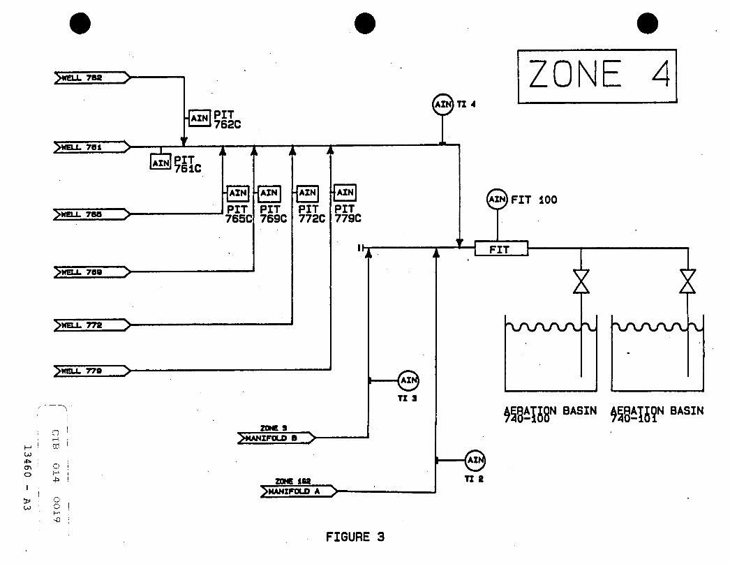
>WELL 761
AZN PIT 762C
(AZN)TX
ZONE 4
BHIc i > i> i t
>WELL 768 V
>WEU. 769 >
>WELL 778 >
>HBX 779 > -
n I
o
- AZN - AZN
PIT 765C
• AZN
PIT 7B9C
PIT 772C
AZN
PIT 779C
ZONE a ^MANIFOLD B
TZ a
AZN) F IT 100
FIT
VffiSP BASIN BASIN
ZONE 1M >MANIFOLD A >
TX 8
FIGURE 3

LSH 1 HT 1 LSH 8 HT 2
M>
MANWAY 3
fMANWAY" 4
737 i
L „ . _
• LSH 3 IHT 9 l1*1 4
HT 4
|__WELL 137_FL0W RATE w ^ j j 233 FLOW RATE
7wELL 236 FLOW RATE" [ WELL 237 FLOW RATE
L8H - LEVEL SWITCH HI6H HT - HEAT THERMOSTAT
FIGURE 4

WELL XXX
00 *» O O
2* on
o : td
FIT XXX
LOW ALARM (SP) CALCULATED FLOW
Ebc%.c8Wr?8k V A L V E «*
PUMP XXX CONTROL
HAND
REMOTE
HEAT THERMOSTAT
^ T O MANIFOLD »
XXXC
LOW ALARM (SP)
ALARM
HIGH ALARM (SP)
ALARM
FLOW CONTROL LOOP
HIGH ALARM (8P)
PLOW CONTROL LOOP IZOH
MANUAL
AUTO
gyMP XXX PUMP XXX LOCAL 8WITCH
HAND
REMOTE
LOW ALARM (SP) ^ 0 U T '
AOUT FLOM RATI (OP) FLOW RATI (PV)
FIGURE 5

WELL XXX
SP PV
MANUAL
AUTO
FLOM RATE (SP) FLO* RATE (PV)
WELL XXX
SP PV
MANUAL
AUTO
FLOW RATE (BP)
FLOW RATE (PV)
WELL XXX
SP PV
MANUAL
AUTO
FLOW RATE (BP)
FLOM RATE (PV)
WELL XXX
SP PV
MANUAL
AUTO
FLOW RATE (8P)
FLOM RATE (PV)
WELL XXX
SP PV
MANUAL
AUTO
FLOM RATE (8P)
FLOM RATE (PV)
WELL XXX
SP PV
MANUAL
AUTO
FLOW RATE (BP) FLOM RATE (PV)
WELL XXX WELL XXX WELL XXX WELL XXX WELL XXX WELL XXX
SP
MANUAL
AUTO
FLOM RATE (BP)
FLOM RATE (PV)
MANUAL
AUTO
FLOW RATE (BP)
FLOM RATE (PV)
MANUAL
AUTO
FLOM RATE (BP)
FLOM RATE (PV)
MANUAL
AUTO
FLOM RATE (SP)
FLOM RATE (PV)
MANUAL
AUTO
FLOM RATE I8P)
FLOM RATE (PV)
MANUAL
AUTO
FLOM RATE (BP)
FLOM RATE (PV)
FIGURE 6

SECTION 15062
FIBERGLASS PIPE AND FITTINGS FOR OFF-SITE FACILITIES
PART 1 GENERAL
1.01 SUMMARY
A. Section includes: 1. Below grade standard and double contained v i n y l - e s t e r
r e s i n r e i n f o r c e d thermosetting r e s i n p i p i n g system 2. Furnishing and i n s t a l l a t i o n of p i p i n g . 3. Te s t i n g of Systems.
1.02 RELATED SECTIONS
A. Section 02144 - E x t r a c t i o n Wells.
B. Section 03430 - Precast Concrete Manways
C. Section 05120 - S t r u c t u r a l Steel
D. Section 05510 - Steel Manway and Metal F a b r i c a t i o n s
E. Section 13410 - General Instrumentation, C o n t r o l , and Mon i t o r i n g Requirements
F. Section 15060 - Fiberglass Pipe and F i t t i n g s
G. Section 15061 - Standard Steel Pipe and F i t t i n g s
H. Section 15100 - Valves
I . Section 15140 - Supports and Anchors
J. Section 15190 - Mechanical I d e n t i f i c a t i o n
K. Section 15260 - Piping I n s u l a t i o n
L. Section 15320 - Well Pumps
M. Section 16855 - Heating Cables and Mats
1.03 REFERENCES
A. American Society f o r Testing and M a t e r i a l s : 1. ASTM D1599 Short-Time Hydrostatic F a i l u r e Pressure of
P l a s t i c Pipe, Tubing and F i t t i n g s . 2. ASTM D2412 External Loading Properties of P l a s t i c Pipe
by P a r a l l e l - P l a t e Loading. 3. ASTM D2444 Test Method f o r Impact Resistance of
Thermoplastic Pipe. 4. ASTM D2105 Test Method f o r L o n g i t u d i n a l Tensile
P r o p e r t i e s . CIB 014 0023
CIBA-GEIGY DE\FB490SPC\15062.CIB 24 February 1993
Fiberglass Pipe and F i t t i n g s For O f f - S i t e F a c i l i t i e s
15062 - 1

5. ASTM D2563 C l a s s i f y i n g V i s u a l Defects i n Glass-Reinforced P l a s t i c Laminate Parts.
6. ASTM D2925 Beam D e f l e c t i o n of Reinforced Thermosetting P l a s t i c Under F u l l Bore Flow.
7. ASTM D2992 H y d r o s t a t i c Design Basis f o r Reinforced Thermosetting Resin Pipe and F i t t i n g s .
8. ASTM D3567 Determining Dimensions of Reinforced Thermosetting Resin Pipe and F i t t i n g s .
9. ASTM D4024 Reinforced Thermosetting Resin Flanges. 10. ASTM D2996 Standard f o r Filament Wound Fiberglass
Pipe. 11. ASTM D2997 Standard f o r C e n t r i f u g a l l y Cast Fiberglass
Pipe. 12. ASTM D2310 Machine made Reinforced Thermosetting Resin
Pipe. 13. ASTM D3839 Underground I n s t a l l a t i o n of FRP Pipe.
B. American National Standards I n s t i t u t e : 1. ANSI B31.3 Chemical Plant and Refinery Piping. 2. ANSI B16.5 Flanges.
C. American Water Works Ass o c i a t i o n : 1. AWWA C950 Glass F i b e r - r e i n f o r c e d Thermosetting Resin
Pipe.
1.04 DEFINITIONS
A. C a r r i e r Pipe - Inner primary pipe c a r r y i n g the f l u i d being t r a n s p o r t e d .
B. Containment Pipe - Outer secondary pipe f o r c o n t a i n i n g the inner pipe and t h a t f l u i d i n case of leakage from the c a r r i e r pipe.
1.05 SYSTEM DESCRIPTION
A. Design Requirements: 1. Design r e i n f o r c e d pipe w a l l i n accordance w i t h ASTM
D2996. 2. Use the design s t r e s s as determined per ASTM D2992,
Procedure A "Long term h y d r o s t a t i c design s t r e s s " . 3. C a r r i e r Pipe.
a. The minimum pressure r a t i n g f o r c a r r i e r pipe and f i t t i n g s (except flanges) s h a l l not be less than:
Diameter (inch) I n t e r n a l PSI External PSI 1-1/2 t o 8 250 15
b. The pressure r a t i n g f o r flanges s h a l l not be less than 150 p s i .
CIB 014 002
CIBA-GEIGY DE\FB490SPC\15062.CIB 24 February 1993
Fiberglass Pipe and F i t t i n g s For O f f - S i t e F a c i l i t i e s
15062 - 2

c. The c a r r i e r pipe w a l l s t i f f n e s s when determined i n accordance t o ASTM D2412 at 5 percent d e f l e c t i o n s h a l l have a minimum s t i f f n e s s o f: Diameter (inch) Pipe S t i f f n e s s ( p s i )
1 11,000 1 1/2 6,100 2 4,900 3 1,400 4 1,200 6 800 8 350
Containment pipe. a. The minimum pressure r a t i n g f o r containment pipe
s h a l l not be less than 100 p s i . J o i n t Design: a. Provide adhesive bonded B e l l by Spigot type or
coupled type j o i n t design f o r f i e l d assembly or flanged method as i n d i c a t e d i n the drawing. A l l socket adhesive j o i n t s s h a l l be over wrapped w i t h f i b e r g l a s s and r e s i n .
b. Design socket or coupling f o r proper e n t r y and bonding.
c. Socket or coupling s h a l l be designed f o r accurate c e n t e r i n g of sp i g o t .
d. Design f i t t i n g s pressure r a t i n g w i t h a minimum sa f e t y f a c t o r of 3:1 when te s t e d i n accordance t o ASTM D1599.
B. Performance Requirements: 1. Maximum pressure requirements:
a. C a r r i e r pipe - 250 p s i . b. Containment pipe - 100 p s i .
2. P i p i n g system s h a l l withstand the f o l l o w i n g temperatures: a. 60 degrees F maximum temperature. b. 0 degrees F minimum temperature.
1.06 SUBMITTALS
A. Provide the f o l l o w i n g Product Data f o r p i p i n g system: 1. Product i n f o r m a t i o n and engineering data, which
includes but not l i m i t e d t o : a. temperature r a t i n g s . b. pressure r a t i n g s . c. h y d r o s t a t i c design basis. d. dimensions. e. mechanical and phys i c a l p r o p e r t i e s . f . bedding requirements f o r buried p i p i n g .
2. L i t e r a t u r e t o show t h a t products provided meet the s p e c i f i e d requirements f o r m a t e r i a l , c o n s t r u c t i o n , f u n c t i o n and t e s t s .
B. Provide i n s t a l l a t i o n procedures f o r : 1. below grade p i p i n g . 2. double contained p i p i n g systems.
CIB 0.14 0
CIBA-GEIGY DE\FB4 90SPC\15062.CIB 24 February 1993
Fiberglass Pipe and F i t t i n g s For O f f - S i t e F a c i l i t i e s
15062 - 3

C. Exceptions t o these s p e c i f i c a t i o n s .
1.07 QUALITY CONTROL PROGRAM
A. Manufacturer; e s t a b l i s h and maintain a Q u a l i t y Control Program t o include w r i t t e n procedures: 1. t o ensure t h a t adequate c o n t r o l of manufacturing, t e s t s
and inspections are e s t a b l i s h e d t o meet the requirements of the drawings, s p e c i f i c a t i o n and co n t r a c t .
2. t o include means f o r c o n t r o l of m a t e r i a l , p a r t s and components, a plan f o r i n s p e c t i o n of manufacturing operations, document c o n t r o l of s p e c i a l processes and procedures f o r f i n a l t e s t s and ins p e c t i o n s .
3. t o ensure t h a t a l l i n s p e c t i o n and t e s t r e s u l t s performed and the r e s u l t s recorded by the Manufacturer.
B. Manufacturer's f a c i l i t y ; s ubject t o s u r v e i l l a n c e and a u d i t of t h i s q u a l i t y c o n t r o l program by the Owner/Engineer.
C. Changes t o Q u a l i t y Control Program: 1. The Manufacturer s h a l l n o t i f y the Owner/Engineer i n
w r i t i n g of a l l changes t o t h i s q u a l i t y c o n t r o l program. 2. Subject t o review and comments by the Owner/Engineer.
1.08 DELIVERY, HANDLING AND STORAGE
A. Permanently mark pipe and f i t t i n g s w i t h manufacturer's name, cl a s s , s i z e , date of manufacture. Mark shop f a b r i c a t e d assemblies i n a d d i t i o n w i t h a piece mark number.
B. Package pipe and f i t t i n g s t o p r o t e c t from shipping and handling damage. P r o t e c t ends of pipe from handling and t r a n s p o r t a t i o n damages.
C. Handle pipe and f i t t i n g s w i t h care t o avoid impact damage or excessive l o c a l i z e d stresses. Do not throw or drop pipe and f i t t i n g s .
D. Inspect each pipe shipment w i t h care on a r r i v a l . N o t i f y c a r r i e r regarding damage or missing items.
E. Use f l a t , stake-bodied t r u c k s wherever p o s s i b l e t o permit side loading and unloading. Do not use short-bodied t r u c k s which allow pipes t o extend unsupported f o r more than three f e e t .
F. B u i l d s t o c k p i l e s on a f l a t base, not on s t r i n g e r s .
G. Do not accept or s t o r e on s i t e items damaged i n shipping.
CIB 014 0026
CIBA-GEIGY DE\FB490SPC\15062.CIB 24 February 1993
Fiberglass Pipe and F i t t i n g s For O f f - S i t e F a c i l i t i e s
15062 - 4

PART 2 PRODUCTS
2.01 MANUFACTURERS
A. This s e c t i o n covers the base m a t e r i a l used i n the manufacture of Reinforced Thermosetting Resin (FRP) pipe.
B. V i n y l - e s t e r Resin; manufactured by Dow Chemical, Ashland, or equivalent s h a l l be used.
C. Gl a s s - f i b e r reinforcement; of E-Glass ( i . e . low a l k a l i glass) made by Owens Corning or eq u i v a l e n t .
D. Fiberglass; made by PPG I n d u s t r i e s Inc. or e q u i v a l e n t .
2.02 MATERIALS
A. Resin s h a l l contain no: 1. T h i x o t r o p i c agents or f i l l e r s . 2. Colorants or pigments.
B. L i n i n g m a t e r i a l ; "C-Veil" glass (chemical r e s i s t a n t glass) or "Nexus" f i b r e ( p o l y e s t e r / v i n y l - e s t e r f i b e r ) wetted w i t h r e s i n as described i n 2.01.B.
C. Provide v i n y l ester adhesive used f o r j o i n i n g pipes, appropriate f o r the product r e s i n s , and f o r the s e r v i c e temperature and pressure. Provide i n k i t s c o n t a i n i n g r e s i n and c u r i n g agents separately packed.
D. MECHANICAL PROPERTIES 1. The c a r r i e r pipe s h a l l meet the f o l l o w i n g minimum
mechanical p r o p e r t i e s : Pipe Property f75°F^ U n i t s Hoop Tensile Stress 22,000 p s i A x i a l Tensile Stress 22,000 p s i Beam Bending Stress 22,000 p s i A x i a l Compressive Stress 22,000 p s i Hoop Tensile Modulus
of E l a s t i c i t y 3.0 x 10 6 p s i A x i a l Tensile Modulus
of E l a s t i c i t y 1.8 x 10 6 p s i Beam Bending Modulus
of E l a s t i c i t y 1.8 x 10 6 p s i
E. DIMENSIONS 1. Pipe outside diameter s h a l l be per ASTM D2996, Table 3
dimensions and tolerances f o r outside diameter equivalent t o i r o n pipe s i z e .
2. The r e i n f o r c e d w a l l thickness of the pipe s h a l l be s u f f i c i e n t t o withstand the design temperature and pressures s p e c i f i e d . I n no case s h a l l i t be less than 0.1 inch.
3. The pipe must meet the tolerances given i n ASTM D 2996/D3567 f o r o v a l i t y .
CIB 014 or
CIBA-GEIGY DE\FB490SPC\15062.CIB 24 February 1993

4. Provide minimum pipe nominal length of 20 f e e t . Longer lengths i n . m u l t i p l e s of ten w i l l be p r e f e r r e d .
5. The r e i n f o r c e d w a l l thickness of f i t t i n g s i . e . , elbow and tee, s h a l l be s u f f i c i e n t t o withstand the design temperature and pressures s p e c i f i e d . I n no case s h a l l i t be less than 1.5 times the w a l l thickness of pipe.
6. Flanges dimensions i n accordance t o ANSI B16.5, Class 150.
2.03 FABRICATION
Shop Assembly: 1. Pipe:
a. Filament-wound pipe: manufacture by f i l a m e n t winding r e s i n impregnated continuous f i b r o u s glass strand r o v i n g or woven glass on outside of poli s h e d s t e e l mandrel i n a predetermined p a t t e r n under c o n t r o l l e d tension.
b. C e n t r i f u g a l cast pipe: manufacture by applying r e s i n and reinforcement t o the i n s i d e of a mold t h a t i s r o t a t e d and heated subsequently polymerizing the r e s i n system.
c. Pipe w i l l have a 0.050 inch r e s i n r i c h (70% minimum) i n t e g r a l i n t e r i o r c o r r o s i o n b a r r i e r . The r e s i n used should be the same as the r e s i n used i n the s t r u c t u r a l w a l l .
d. The s t r u c t u r a l w a l l of pipe w i l l be f i l a m e n t wound or C e n t r i f u g a l l y cast w i t h minimum 60% glass reinforcement impregnated i n r e s i n per 2.01.B.
e. The e x t e r i o r of the pipe t o be coated w i t h pure r e s i n r i c h (90-95 percent) coating.
f . Double contained p i p i n g : 1. inner c a r r i e r pipe: c a r r y i n g the f l u i d being
transported. 2. outer containment pipe f o r c o n t a i n i n g the inner
pipe and t h a t f l u i d i n case of leakage from the c a r r i e r pipe.
3. Sizes r e q u i r e d are: CARRIER PIPE (inch) CONTAINMENT PIPE (inch)
1 1/2 3 2 4 3 6 4 8 6 10 8 12
4. The annular space between the c a r r i e r pipe and the Containment pipe s h a l l be a minimum of 0.75 inch, t o accommodate leak d e t e c t i o n cable such as Permalert ESP.
5. The system s h a l l be an ' a l l bonded' type, using B e l l and Spigot or coupling adhesive bonded j o i n i n g methods f o r both c a r r i e r and containment pipes and f i t t i n g s .
6. The c a r r i e r pipe s h a l l be c e n t r a l i z e d i n s i d e the containment pipe, the spacing s h a l l not be more than standard recommended support spacing. The c e n t r a l i z e r s s h a l l be manufacturer's standard m a t e r i a l s and s h a l l have s i m i l a r c orrosion r e s i s t a n c e as the pipe, and
CIBA-GEIGY DE\FB490SPC\15062.CIB 24 February 1993
Fiberglass Pipe and F i t t i n g s For O f f - S i t e F a c i l i t i e s
15062 - 6

s h a l l be designed such t h a t i t s h a l l allow the leak d e t e c t i o n cable t o be i n s t a l l e d and p u l l e d through i t a f t e r pipe i n s t a l l a t i o n . The c e n t r a l i z e r s s h a l l be bonded t o the c a r r i e r pipe and pre-assembled i n the f a c t o r y . A p u l l rope must be provided i n each se c t i o n t o permit i n s t a l l a t i o n of the leak d e t e c t i o n cable.
7. The double contained p i p i n g w i t h c e n t r a l i z e r s s h a l l be a l l pre-assembled i n the f a c t o r y and shipped t o s i t e w i t h end p r o t e c t o r s .
8. Containment pipe s h a l l be designed t o permit v i s u a l i n s p e c t i o n of c a r r i e r pipe field-made bonded j o i n t s d u r i n g h y d r o s t a t i c t e s t . I nspection of c a r r i e r pipe j o i n t s d u r i n g h y d r o s t a t i c t e s t i s r e q u i r e d p r i o r t o the bonding of containment pipe j o i n t s .
2.04 FITTINGS
A. Manufacture f i t t i n g and flanges by f i l a m e n t wound c o n s t r u c t i o n using v i n y l e s t e r r e s i n .
B. Double contained f i t t i n g s s h a l l be f a c t o r y assembled as one s i n g l e u n i t . Both c a r r i e r and containment f i t t i n g s s h a l l be f a b r i c a t e d by f i l a m e n t winding process.
C. F i t t i n g s s h a l l be filament-wound c o n s t r u c t i o n socket-ended or flanged type. The f i t t i n g s w i l l have a r e s i n r i c h l i n e r ( c o r r o s i o n b a r r i e r ) 0.05" t h i c k . The socket-ended f i t t i n g s s h a l l have a pressure r a t i n g equal t o or greater than the pipe. Saddle type branch connections are not acceptable, except f o r saddles w i t h one inch o u t l e t f o r i n s t r u m e n t a t i o n connections, d r a i n s and vents.
D. The c a r r i e r f i t t i n g of the double containment p i p i n g s h a l l have the same c o n s t r u c t i o n as above.
E. A l l elbows are long r a d i u s unless otherwise s p e c i f i e d .
2.05 FLANGES
A. Provide flanges of filament-wound c o n s t r u c t i o n . D r i l l i n g and dimensions s h a l l be per ANSI B16.5.
B. Provide nuts and b o l t s of r e i n f o r c e d p l a s t i c such as superstud CR by Permali f o r flanges.
C. Provide f u l l faced gasket, 1/8 inch t h i c k from an elastomeric/rubber m a t e r i a l w i t h a Shore A durometer of 60 plus or minus 5.
2.06 SOURCE QUALITY CONTROL
A. Testing: 1. Pressure t e s t i n g :
a. Test pipe t o 250 p s i and hold f o r a minimum 2 minutes.
b. C a r e f u l l y check pipe f o r leaks d u r i n g t e s t period.
CIBA-GEIGY DE\FB490SPC\15062.CIB 24 February 1993
Fiberglass Pipe and F i t t i n g s For O f f - S i t e F a c i l i t i e s
15062 - 7

c. Test f i t t i n g s t o 250 p s i pressure and hold f o r one minute and check f o r leaks.
d. Pipes and f i t t i n g s not passing above t e s t s s h a l l be re j e c t e d .
e. Double contained f i t t i n g s and p r e f a b r i c a t e d assemblies s h a l l be t e s t e d : c a r r i e r 250 p s i , containment 10 p s i a i r pressure.
2. V e r i f y diameter and w a l l thickness i n accordance w i t h ASTM D3567.
3. V i s u a l i n s p e c t i o n f o r pipe s h a l l be c a r r i e d out per ASTM D2563.
4. Impact resistance t e s t s h a l l be c a r r i e d out per ASTM D2444.
5. Pipe s t i f f n e s s t e s t s h a l l be done i n accordance t o ASTM D2412.
6. Test c e r t i f i c a t e s s h a l l be made a v a i l a b l e t o the Owner when requested.
7. A l l m a t e r i a l s and f a b r i c a t i o n s h a l l be l i a b l e f o r in s p e c t i o n and t e s t i n g as per requirements of the above standards and s p e c i f i c a t i o n s . The Manufacturer s h a l l a f f o r d the i n s p e c t i o n w i t h o u t charge.
8. A l l p i p i n g and f i t t i n g s s h a l l be subjected t o a f i e l d , v i s u a l and dimensional check by the Contractor p r i o r t o i n s t a l l a t i o n .
9. Test double contained p i p i n g before b a c k f i l l i n g , per the manufacturers recommendation. Testing s h a l l be performed t o minimize open t r e n c h i n g .
10. A f t e r t e s t i n g i s complete on the inner pipe, j o i n containment p i p i n g . Each day p a r t i a l l y cover p i p i n g except f o r area around j o i n t s . A f t e r a l l t e s t i n g i s completed, b a c k f i l l pipe t r e n c h .
B. Manufacturer's Representative: 1. Provide f a c t o r y r e p r e s e n t a t i v e f o r a minimum of 5
mandays excluding weekends and t r a v e l time t o conduct classes a t Owner's s i t e on p i p i n g system i n s t a l l a t i o n technigues and t e s t i n g and t o a s s i s t i n i n s t a l l a t i o n .
2. During i n s t a l l a t i o n of double contained p i p i n g a f a c t o r y r e p r e s e n t a t i v e s h a l l be present dur i n g the e n t i r e course of i n s t a l l a t i o n .
C. Performance: 1. When c l a s s i f i e d i n accordance w i t h ASTM D2310/D2996 the
minimum performance of pipe s h a l l meet RTRP, Type I or I I , Grade I I , Class E, Hoopstress HDB, C l a s s i f i c a t i o n E.
PART 3 EXECUTION
3.01 INSTALLATION
General: 1. Pipe i n s t a l l a t i o n s h a l l be i n s t r i c t accordance w i t h
Manufacturer's w r i t t e n procedures and i n s t r u c t i o n s and these s p e c i f i c a t i o n s .
CIB 014 00
CIBA-GEIGY DE\FB4 9 0SPC\15062.CIB 24 February 1993
Fiberglass Pipe and F i t t i n g s For O f f - S i t e F a c i l i t i e s
15062 - 8

2. Tools and m a t e r i a l s required f o r i n s t a l l a t i o n of pipe assembly s h a l l be as recommended by the Manufacturer.
3. Workmen making j o i n t s s h a l l be thoroughly f a m i l i a r w i t h the pipe manufacturer's assembly i n s t r u c t i o n s , and s h a l l f o l l o w them i n a l l respects.
B. C u t t i n g : 1. Make end cuts square, using sharp, f i n e - t o o t h e d
hacksaw, or an abrasive wheel. 2. I f s p i g o t ends must be prepared i n the f i e l d , they
s h a l l be made using c u t t i n g or g r i n d i n g equipment t h a t operates i n a continuous r o t a t i o n a l motion of e i t h e r the pipe or the t o o l .
C. Surface Preparation: 1. F i t t i n g and pipe bonding surfaces s h a l l be sanded
thoroughly j u s t p r i o r t o assembly, using a coarse g r i t emery c l o t h . Sanding s h a l l be deemed s a t i s f a c t o r y only i f a f r e s h new surface w i t h a n o t i c e a b l e roughness i s achieved.
2. Dust from bonding surfaces s h a l l be removed by wiping w i t h a clean c l o t h . Solvent cleaning s h a l l be used only i f chemical contamination i s suspected. I f used, solvents s h a l l be 100% evaporative.
D. J o i n t Assembly: 1. The spigot end s h a l l be marked a t a distance equal t o
the b e l l or coupling depth plus one inch, and t h i s mark used t o confirm f u l l i n s e r t i o n when assembled.
2. Adhesive; obtained from the pipe manufacturer: a. thoroughly and c a r e f u l l y mixed i n accordance w i t h
the manufacturer's i n s t r u c t i o n s . b. maintained a t 70°F or above p r i o r t o mixing, and
s h a l l be a p p l i e d w i t h i n 20 minutes a f t e r mixing. c. any adhesive t h a t becomes warm due t o the c u r i n g
r e a c t i o n before being a p p l i e d s h a l l be discarded. d. applied i n a t h i n l ayer on the b e l l bonding
surfaces and l i b e r a l l y on the s p i g o t bonding surfaces.
3. Pipe s h a l l be i n s e r t e d slowly i n t o b e l l or coupling u n t i l pipe r e s t s f i r m l y against pipe stop. I f necessary, f i r m but not excessive hammer blows s h a l l be used t o d r i v e the j o i n t home, w i t h wood blocks or other s u i t a b l e means being used t o avoid l o c a l i z e d s t r e s s .
4. The j o i n t s h a l l not be subjected t o operation loads p r i o r t o adhesive cure. Cure times and accelerated cure methods as recommended by the manufacturer s h a l l be followed. Added heat, as by the manufacturer's recommended e l e c t r i c blanket, s h a l l be mandatory i n ambient temperatures below 70°F f o r pipe and f i t t i n g s .
E. Flange: 1. The p i p i n g s h a l l not be sprung or forced i n t o p o s i t i o n
i n the system. Flange faces, e s p e c i a l l y when mating w i t h s t e e l , s h a l l be i n p a r a l l e l alignment before b o l t i n g .
CIB 014 0
CIBA-GEIGY DE\FB490SPC\15062.CIB 24 February 1993
Fiberglass Pipe and F i t t i n g s For O f f - S i t e F a c i l i t i e s
15062 - 9

2. Manufacturer torque recommendations s h a l l be followed. 3. Assemble b o l t s as per manufacturer recommended
sequence.
F. Bedding and b a c k f i l l i n g of pipe: Manufacturers recommendation and AWWA C950 requirements.
G. Double Contained Piping: 1. Assemble c a r r i e r pipe and t e s t p r i o r t o assembling the
containment pipe. 2. V i s u a l l y inspect c a r r i e r pipe j o i n t s f o r leaks during
t e s t . 3. J o i n containment p i p i n g and t e s t containment per
Manufacturers recommendation h y d r o s t a t i c a l l y t o insure i n t e g r i t y of system.
4. I n s t a l l leak d e t e c t i o n cable a f t e r t e s t i n g of containment p i p i n g system.
H. External damage of p i p i n g by impact s h a l l be prevented. Should any damage occur then Contractor s h a l l f u l l y replace or r e p a i r the damaged pipe or f i t t i n g .
I . Repairing: 1. Manufacturer s h a l l provide r e p a i r procedures. 2. Repair should be c a r r i e d out by t r a i n e d personnel only. 3. Repair pipe only i f the r e p a i r does not adversely
a f f e c t pipes' performance.
3.02 FIELD TESTING
A. Hydrotesting c a r r i e r pipe: 1. A f t e r i n s t a l l a t i o n , f i l l s ections of c a r r i e r pipe
system w i t h water and h y d r o s t a t i c a l l y t e s t t o 250 p s i . 2. Hold pressure f o r 30 minutes continuously. 3. At the end of t h i s time inspect pipe and f i t t i n g s f o r
leaks. Repair leaks and r e - t e s t system u n t i l no leaks are found.
B. Testing containment pipe: 1. A f t e r i n s t a l l a t i o n , t e s t containment pipe system t o 10
p s i g a i r pressure. 2. Hold pressure f o r 30 minutes continuously. 3. At the end of t h i s time inspect pipe and f i t t i n g s f o r
leaks w i t h soap water. Repair leaks and r e - t e s t system u n t i l no leaks are found.
END OF SECTION
CIB 014 0
CIBA-GEIGY DE\FB490SPC\15062.CIB 24 February 1993
Fiberglass Pipe and F i t t i n g s For O f f - S i t e F a c i l i t i e s
15062 - 10

SECTION 16050
BASIC MATERIALS AND METHODS
PART 1 - GENERAL
1.01 SECTION INCLUDES
A. Materials, components, fittings, equipment and installation methods used in Work required by Division 16 common to more than one Section.
1.02 AREA CLASSIFICATION AND EQUIPMENT ENCLOSURES
A. Classification: Except where specifically indicated, the area i s considered non-hazardous relative to Article 500 of the N.E.C.
B. Enclosures: Comply with the following c r i t e r i a , unless noted otherwise: 1. Installations outdoors or in the process areas;
4, unless otherwise noted. 2. Installations indoors, unoccupied areas: NEMA 4
with exception of MCC #1.
1.03 DISSIMILAR METALS
A. Do not use dissimilar metals in direct contact unless explicitly stated or shown on Drawings.
B. Permitted; copper-free aluminum boxes and fittings with rigid galvanized steel conduit (RGS) in conduit systems. Copper-free i s containing less than 0.4 percent copper.
C. E l e c t r i c a l conductors; copper unless otherwise noted. Tin plating, s i l v e r plating, and other treatment; provide as required or specified.
1.04 FINISH
A. In addition to the finish requirements contained in Division 1, the following are minimum requirements for the e l e c t r i c a l installation: 1. Galvanizing:
a. Zinc coating applied to bright metal by processes and to thickness required by the applicable governing standard.
b. Clean surface and coat with 2 coats of a cold galvanizing compound where zinc coating i s marred or removed.
CIBA-GEIGY Basic Materials and Methods February 18, 1993 16050-1

B. Cast Metals: 1. Cast aluminum f i t t i n g s and enclosures; natural
f i n i s h , unless noted otherwise. 2. Cast ferrous metal f i t t i n g s and enclosures;
e l e c t r o s t a t i c a l l y deposited zinc coating and a f i n a l coating of aluminum lacquer, such as Crouse-Hinds Feraloy or equal.
C. Stainless steel f i t t i n g s and enclosures; natural f i n i s h , unless otherwise noted.
D. Sheet Ferrous Metal: 1. NEMA 1 Painted items; f i n i s h i n accordance with
manufacturer's standard practice, but include as a minimum 1 f i n i s h coat of a c r y l i c enamel and 1 primer coat applied over a phosphatized surface.
2. NEMA 12; 2 coats of a c r y l i c enamel and 2 primer coats applied over a phosphatized surface. Acceptable alternate; coating with e l e c t r o s t a t i c a l l y deposited and treated polyester powder over phosphatized surface.
E. Color; Unless noted otherwise, i n accordance with ANSI-Z55.1 and the following: 1. Panels and/or panel i n t e r i o r s f o r device
mounting; white. 2. Panel i n t e r i o r s and general enclosure i n t e r i o r s
may be ANSI-61. 3. C i r c u i t breaker panelboard, motor s t a r t e r
enclosures, and sim i l a r enclosures may have ANSI-61 i n t e r i o r s .
PART 2 - PRODUCTS
2.01 CONDUITS AND FITTINGS
A. Conduit: 1. Conduit f o r i n t e r i o r w i r i n g , surface mounted
(exposed); r i g i d galvanized steel (RGS). 2. Do not use conduit less than 3/4 inch nominal
diameter trade size, unless noted otherwise. 3. Conduit t o be direct-buried below grade; PVC,
schedule 40, approved f o r d i r e c t b u r i a l , unless otherwise noted.
4. Conduit f o r low voltage signal wire; RGS. 5. Plug unused conduit openings with a sealing
compound, 0-Z Gedney "DUX" or equal. 6. In manways liguidtite (sealtite) conduit for
conduit from instrument boxes to rigid conduit or enclosures.
CIBA-GEIGY Basic Materials and Methods February 18, 1993 16050-2
CIB 014 0034

B. Standards: Conduit, conduit fittings, and outlet bodies: 1. Federal Specification WW-C-566. 2. Rigid Steel Conduit (zinc coated) (RGS); ANSI
Standard C80.1. 3. Rigid Non-Metallic Conduit (PVC); UL Standard 651
Schedule 40 PVC. 4. Flexible metal conduit; UL 1.
C. Reference Specifications: 16110 Conduits:
2.02 WIRE AND CABLE
A. General: 1. Sizes; American Wire Gage (AWG). 2. Insulated wire and cable; 98 percent
conductivity, class B stranded, in accordance with ASTM Designation B8.
3. Soft drawn bare copper (SDBC); ASTM Designation Bl-56.
4. Wires; Class B stranding per ASTM B3. 5. Use no wire smaller than No. 12 AWG for power
circ u i t s unless noted otherwise.
B. Reference Specification: 16123 Wires and Cables
C. A l l 35KV rated cable shall be as described in PECO "Blue Book".
2.03 BOXES AND CABINETS
A. General: 1. Provide boxes as shown on Drawings and specified. 2. Cast metal outlet boxes; Federal Specification
W-C-586 and UL 514. 3. Stamped steel boxes; Federal Specification
W-0-8219. 4. NEMA 4X boxes; supplied with stainless steel
screws.
B. Types: 1. Boxes and conduit fittings for surface-mounted
work in process areas or weatherproof installation; NEMA 4X.
2.04 SAFETY SWITCHES
A. General: Type "H", heavy duty, horsepower rated, industrial type, with enclosures as shown on Drawings.
CIBA-GEIGY February 18, 1993
Basic Materials and Methods 16050-3

B.
2.05
A.
B.
C.
2.06
A.
B.
C.
2.07
A.
B.
Manufacturers: Westinghouse, General E l e c t r i c , or Square D.
PANELBOARDS
General: 1. Provide complete panelboards, NEMA 12 and NEMA 1,
as specified, as shown on the panelboard schedules, and on Drawings.
2. Panelboards s h a l l contain phase bus bars, insulated neutral bar, main, and branch c i r c u i t breakers.
3. C i r c u i t breaker type panelboards; conform t o Federal Specifications W-P-115a.
4. C i r c u i t breakers; Federal Standard W-C-375b.
C i r c u i t Breakers: 1. Panelboards; dead f r o n t type, with frame, t r i p
and i n t e r r u p t i n g characteristics indicated on panelboard schedules.
2. Arrange as indicated on the panel schedules and as specified.
3. C i r c u i t breakers; molded case type with both thermal and magnetic t r i p elements with ambient temperature compensation.
4. Trip elements; interchangeable type, where indicated.
5. Main breakers; centered at top or bottom as shown on Drawings.
Reference Specification: 16470 Panelboards.
DRY-TYPE TRANSFORMERS
Provide dry-type, self-cooled transformers conforming t o NEMA ST-20.
D i s t r i b u t i o n transformers; rated as shown on Drawings.
Manufacturers: Square D, Westinghouse, ACME.
TERMINAL CABINETS
Provide terminal cabinets as specified and as shown on Drawings. 1. Type of enclosure f o r respective panels; NEMA 4X
or as shown on Drawings.
Terminal cabinets; construct of stamped or drawn sheet metal welded a l l around.
CIBA-GEIGY February 18, 1993
Basic Materials and Methods 16050-4

1. Door; hinge on l e f t side and clamp type latches on the right side.
2. Provide provision for padlock on right side. 3. NEMA 4X enclosures; stainless steel, unless
otherwise noted. 4. Provide separate back panels for mounting
terminal blocks. 5. Provide terminal blocks as specified. Twenty
percent spare terminals with a minimum of 12 terminals in each box.
C. Terminal panels; as manufactured by Hoffman.
2.08 GROUNDING
A. Provide equipment and materials to ground building as shown on Drawings. 1. Ground rods; copper-clad steel, 3/4 inch diameter
by a minimum of 10 feet long with pointed ends and chamfered tops.
2. Each rod shall have 5 ohms resistance (maximum) when measured by a ground megger. I f this i s not achieved, drive additional rods and connect with number 4/0 stranded, drawn bare copper conductor (SDBC).
3. Connect ground rods to building steel with number 2/0 SDBC and exothermic welds.
4. Connect ground cables to ground rods with copper compression type ground rod to cable connector, Burndy Type YGLR or equal.
5. Ground equipment by an NEC compliant ground which shall run with the power c i r c u i t .
6. Tie motor control center, high voltage switchgear, and low voltage switchgear ground busses directly to ground by at least two ground conductors per bus.
7. Ground rods; Hubbard, Chance, Copperweld, or equal.
8. Coat connections with Dow-Corning 3145 RTV. 9. A l l system and equipment grounding shall be in
accordance with Section 250, National E l e c t r i c Code, latest edition.
PART 3 EXECUTION
3.01 GENERAL
A. Supply, i n s t a l l , test, calibrate, start-up, and operate el e c t r i c a l systems as shown on Drawings, as required by specifications, and in accordance with the NEC, the NESC, and OSHA.
CIBA-GEIGY Basic Materials and Methods February 18, 1993 16050-5
CIB 014

3.02 ABOVE-GROUND INSTALLATION
A. I n s t a l l above-ground installation as shown on Drawings, locate conduit banks, and verify noninterference with equipment and piping. 1. Design and check conduit supports for structural
integrity. 2. Conduit racks may be fabricated from angle iron
u t i l i z i n g malleable iron korn clamps with clamp backs or strut type channel systems and galvanized steel clamps.
3. Strut type, full-thread hanger rod; 1/2 inch diameter minimum.
4. Angle iron outdoors or in process areas; galvanized, painted.
5. Coat galvanized surfaces with 2 coats of a cold galvanizing compound after welding; LPS-1G or equal.
B. Temporarily seal conduit to prevent entry of foreign objects as each run i s completed.
C. Clean conduits by pulling a mandrel through them before pulling wire or cable.
D. Provide and i n s t a l l pullboxes or pulling type outlet bodies to f a c i l i t a t e pulling wire and cable as required.
E. I n s t a l l e l e c t r i c a l equipment such as lighting panels, transformers, junction boxes, and control panels prior to connecting conduit. 1. Connect equipment such as motors and
field-mounted instruments with liquid tight flexible conduit with external grounding jumper.
F. Test installed wiring and insulation and record results. Megger power, lighting and control wire insulation: 1. Prior to connection to equipment, and 2. Prior to i n i t i a l energization of the equipment.
G. Megger motors prior to connection; readings shall be greater than 5,000,000 ohms. 1. Use a 500 volt megger for motors and 120/208 volt
c i r c u i t s . 2. Use a 1,000 volt megger for 480 volt c i r c u i t s .
H. Turn on heat tracing cir c u i t s to verify energization of heat trace cable.
CIBA-GEIGY Basic Materials and Methods February 18, 1993 16050-6
CIB 014 0038

3.03
A.
B.
C.
D.
E.
F.
G.
H.
3.04
A.
B.
3.05
A.
UNDERGROUND INSTALLATION
I n s t a l l w i r i n g system as shown on Drawings.
Lay out location of underground conduits and cables, v e r i f y i n g routing and depth to avoid underground interferences.
Follow general routing f o r underground e l e c t r i c a l duct and conductors shown on Drawings.
Terminate conduit where i t stubs up and i s terminated at grade with a grounding bushing.
Terminate conduit that stubs i n t o a sheet metal J-Box with a threaded hub adapter, T & B Bul l e t .
Use RGS, large radius elbows and conduit with appropriate PVC to steel adaptors below grade wherever underground PVC conduit extends upward and exits from grade in concrete or earth or connects to RGS nipple to manway or pullbox.
Provide As-Built Drawings, showing dimension, exact location of underground cable and conduit and stub-ups p r i o r t o acceptance.
I n s t a l l a 1/4-inch-diameter, 200-pound t e s t , nylon l i n e i n each unused conduit.
INSTALLATION OF WIRE AND CABLE
Pullboxes: 1. Provide pullboxes or p u l l i n g type o u t l e t bodies
where required t o f a c i l i t a t e p u l l i n g wire and cable.
2. Use p u l l i n g compound.
Wire I d e n t i f i c a t i o n : 1. Provide wire markers t o i d e n t i f y each conductor
at equipment terminals and i n intermediate terminal boxes.
PENETRATIONS OF STRUCTURE
Seal opening to the same degree of security required f o r the o r i g i n a l p a r t i t i o n i f the e l e c t r i c a l i n s t a l l a t i o n penetrates w a l l , f l o o r , or other s t r u c t u r a l p a r t i t i o n .
CIBA-GEIGY February 18, 1993
Basic Materials and Methods 16050-7
CIB 0.14 0039

B. Use approved f i r e - s t o p methods and m a t e r i a l s i f p a r t i t i o n s are f i r e - r a t e d .
C. Use cable s e a l s , OZ/Gedney, or equal to sea l cable entering o f f - s i t e manways.
3.06 MANUALS AND TRAINING
A. Provide Operating and Maintenance (O&M) manuals i n accordance w i t h Section 01300.
B. Provide a t r a i n i n g program f o r major items of equipment, i n c l u d i n g : 1. A minimum, 40 hours classroom i n s t r u c t i o n and 40
hours of a c t u a l equipment op e r a t i o n . 2. Review of O&M manuals and procedures f o r
equipment, c o n t r o l s , and i n t e r f a c e s w i t h D i v i s i o n 13.
C. I n s t r u c t o r s ; f a c t o r y - c e r t i f i e d .
END OF SECTION
CIBA-GEIGY February 18, 1993
Basic M a t e r i a l s and Methods 16050-8
CIB 014 0040
SECTION 16111
CONDUIT
PART 1 GENERAL
1.01 SECTION INCLUDES
A. Rigid metal conduit (RGS).
B. Flexible metal conduit.
C. Liquidtight flexible metal conduit.
D. E l e c t r i c a l metallic tubing (EMT).
E. Nonmetal conduit (PVC).
F. Fittings and conduit bodies.
1.02 RELATED SECTIONS
A. Section 16010 - Basic E l e c t r i c a l Requirements.
B. Section 16050 - Basic Materials & Methods.
C. Section 16190 - Supporting Devices.
D. Section 16195 - Ele c t r i c a l Identification.
1.03 REFERENCES
A. ANSI C80.1 - Rigid Steel Conduit, zinc coated.
B. ANSI C80.3 - Ele c t r i c a l Metallic Tubing, zinc coated.
C. ANSI/NEMA FB 1 - Fittings, Cast Metal Boxes, and Conduit Bodies for Conduit and Cable Assemblies.
D. ANSI/NFPA 70 - National Ele c t r i c Code.
E. NECA "Standard of Installation".
F. NEMA RN 1 - Polyvinyl Chloride (PVC) Externally Coated Galvanized Rigid Steel Conduit and Intermediate Metal Conduit.
G. NEMA TC 2 - Elec t r i c a l Plastic Tubing (EPT) and Conduit (EPC-40 and EPC-80).
CIBA-GEIGY Conduit February 18, 1993 16111-1
CIB 014 0041

H.
1.04
A.
1.05
A.
1.06
A.
B.
1.07
A.
B.
C.
D.
1.08
A.
B.
C.
NEMA TC 3 - PVC Fittings for Use with Rigid PVC Conduit and Tubing.
DESIGN REQUIREMENTS
Conduit Sizes: ANSI/NFPA 70 (National E l e c t r i c Code, latest edition).
SUBMITTALS
Submit under provisions of Division 1.
REGULATORY REQUIREMENTS
Conform to requirements of ANSI/NFPA 70.
Furnish products listed and class i f i e d by Underwriters Laboratories, Inc. as suitable for purpose specified and shown.
DELIVERY, STORAGE, AND HANDLING
Deliver, store, protect, and handle products to si t e under provisions of Section 01300.
Accept conduit on si t e . Inspect for damage.
Protect conduit from corrosion and entrance of debris by storing above grade. Provide appropriate covering.
Protect PVC conduit from sunlight.
PROJECT CONDITIONS
Verify that f i e l d measurements are as shown on Drawings.
Verify routing and termination locations of conduit prior to rough-in.
Conduit routing i s shown on Drawings in approximate locations unless dimensioned. Route as required to complete wiring system.
CIBA-GEIGY February 18, 1993
Conduit 16111-2
CIB 0.14 004

PART 2 PRODUCTS
2.01 CONDUIT REQUIREMENTS
A. Conduit: 1. Conduit f o r i n t e r i o r w i r i n g or surface mounted
(exposed); r i g i d galvanized steel (RGS). 2. Conduit which i s imbedded i n slabs; PVC. No
conduit s h a l l have a nominal diameter of less than 3/4 inch trade size, unless noted otherwise.
3. Conduit t o be direct-buried below grade s h a l l be PVC, schedule 40, approved f o r d i r e c t b u r i a l , unless otherwise noted.
4. I n o f f i c e areas and w i t h i n suspended c e i l i n g s , e l e c t r i c a l m e t a l l i c tubing (EMT) may be used. Conduit i n process areas s h a l l be RGS. A l l unused conduit openings s h a l l be plugged with a sealing compound, 0-Z Gedney "EX" or equal, or conduit caps.
B. Standards. A l l conduit, conduit f i t t i n g s and o u t l e t bodies s h a l l comply with the following standards: 1. Federal Specification WW-C-566. 2. Rigid steel conduit (zinc coated) (RGS) - ANSI
Standard C80.1. 3. Rigid non-metallic conduit (PVC) - UL Standard
651 Schedule 40 PVC unless otherwise specified. 4. Flexible metal conduit - UL 1.
C. Conduit F i t t i n g s : 1. Running Threads: Running threads, Erickson or
s p l i t couplings s h a l l not be used. Couplings s h a l l be as manufactured by O.Z./Gedney, Thomas & Betts, or equal.
2. Wall Entrance Seals: Entrance seals s h a l l be provided where conduits pass through e x t e r i o r concrete or masonry below grade. I n manways, the entrance seals s h a l l seal the cables to withstand f i f t y foot head of water without leakage. Where cable seals w i l l only accept a 4" RGS conduit, a 4" RGS nipple s h a l l be i n s t a l l e d and reduced to the proper size conduit e x i t i n g the area. Where the conduit entering and/or e x i t i n g the manway i s PVC, a t r a n s i t i o n coupling w i l be provided and i n s t a l l e d to provide a r i g i d galvanized t r a n s i t i o n . Entrance seals s h a l l be O.Z./Gedney Type PSC, Spring City Type WEP, WDP, or equal.
3. Conduit Hubs: Threaded hubs s h a l l be provided f o r RGS conduit entry to sheet metal boxes, and sh a l l be complete with i n t e g r a l insulated throat, captive 0-ring seal and oversize nut and conduit bushing. Hubs sha l l provide co n t i n u i t y of ground
CIBA-GEIGY February 18, 1993
Conduit 16111-3

between the conduit and sheet metal enclosure. Hubs s h a l l be T&B "Bulle t " . Cast boxes s h a l l have i n t e g r a l threaded hubs.
4. Expansion F i t t i n g s : Weatherproof expansion f i t t i n g s s h a l l be provided where conduits cross expansion j o i n t s and/or as noted on the plans. Expansion f i t t i n g s s h a l l be complete with bonding jumpers. Expansion f i t t i n g s s h a l l be O.Z./Gedney Type "EX", or equal.
5. Thread lubricant s h a l l be used f o r metal conduit threads - Crouse-Hinds STL, or equal.
PART 3 EXECUTION
3.01 INSTALLATION
A. I n s t a l l conduit i n accordance with NECA "Standard of I n s t a l l a t i o n " .
B. I n s t a l l nonmetallic conduit i n accordance with manufacturer's ins t r u c t i o n s .
C. Arrange supports t o prevent misalignment during wi r i n g i n s t a l l a t i o n .
D. Support conduit using coated steel or malleable i r o n straps, l a y - i n adjustable hangers, c l e v i s hangers, and s p l i t hangers.
E. Group related conduits; support using conduit rack. Construct rack using steel channel; provide space on each for 25 percent additional conduits. Use u n i s t r u t members provided i n manways f o r conduit supports.
F. Fasten conduit supports t o buil d i n g structure and surfaces under provisions of Section 16190.
G. Do not support conduit with wire or perforated pipe straps. Remove wire used f o r temporary supports.
H. Do not attach conduit t o c e i l i n g support wires.
I . Arrange conduit t o maintain headroom and present neat appearance.
J. Route exposed conduit p a r a l l e l and perpendicular t o walls.
K. Route conduit i n s t a l l e d above accessible c e i l i n g s p a r a l l e l and perpendicular t o walls.
CIBA-GEIGY Conduit February 18, 1993 16111-4
CIB 014 0044

L.
M.
N.
O.
P.
Q.
R.
S.
T.
U.
V.
W.
X.
3.02
A.
Route conduit i n and under slab from point-to-point.
Do not cross conduits i n slab.
Maintain adequate clearance between conduit and piping. A minimum of 2 feet-6 inches between conduits in ground and FRP pipeline.
Maintain 12 inch (300 mm) clearance between conduit and surfaces with temperatures exceeding 104°F (40°C).
Cut conduit square using saw or pipecutter; de-burr cut ends.
Bring conduit t o shoulder of f i t t i n g s ; fasten securely.
Join nonmetallic conduit using cement as recommended by manufacturer. Wipe nonmetallic conduit dry and clean before j o i n i n g . Apply f u l l even coat of cement to e n t i r e area inserted i n f i t t i n g . Allow j o i n t t o cure f o r 20 minutes, minimum.
I n s t a l l no more than equivalent of three 90-degree bends between boxes. Use conduit bodies t o make sharp changes i n d i r e c t i o n , as around beams. Use factory elbows f o r bends i n metal conduit larger than 2 inch (50 mm) size.
Avoid moisture traps; provide junction box with drain f i t t i n g at low points i n conduit system.
Use suitable caps t o protect i n s t a l l e d conduit against entrance of d i r t and moisture.
Ground and bond conduit i n accordance with N.E.C.
I d e n t i f y conduit under provisions of Section 16195.
Use approved spacers to stabilize and separate conduits in ground.
INTERFACE WITH OTHER PRODUCTS
I n s t a l l conduit t o preserve f i r e resistance r a t i n g of p a r t i t i o n s and other elements.
END OF SECTION
CIBA-GEIGY February 18, 1993
Conduit 16111-5
CIB 014 004

SECTION 16123
WIRE AND CABLE
PART 1 GENERAL
1.01 SECTION INCLUDES
A. Wire and cable rated 600 volt and less.
B. Single conductor wire.
C. Direct buried power and control.
D. Signal wire and cable.
E. Wiring connectors and connections.
1.02 RELATED SECTIONS
A. Section 16010 - Basic E l e c t r i c a l Requirements.
B. Section 16050 - Basic Material and Methods.
C. Section 16195 - Identification.
D. Section 16301 - Underground E l e c t r i c a l Work.
E. Division 13.
1.03 REFERENCES
A. ANSI/NFPA 70 - National E l e c t r i c a l Code, latest edition.
1.04 SUBMITTALS
A. Submit under provisions of Section 01300.
B. Product Data: Provide for each cable assembly type.
C. Test Reports: Indicate procedures and values obtained.
D. Manufacturer's Installation Instructions: Indicate application conditions and limitations of use stipulated by product testing agency specified under Regulatory Requirements.
CIBA-GEIGY Wire and Cable February 18, 1993 16123-1
CIB 0.14

1.05
A.
1.06
A.
B.
1.07
A.
B.
C.
D.
1.08
A.
B.
C.
D.
E.
QUALIFICATIONS
Manufacturer: Company s p e c i a l i z i n g i n manufacturing products specified i n t h i s Section with minimum three years documented experience.
REGULATORY REQUIREMENTS
Conform to requirements of ANSI/NFPA 70.
Furnish products l i s t e d and c l a s s i f i e d by Underwriters Laboratories, Inc. as suitable for purpose specified and shown.
PROJECT CONDITIONS
Verify that f i e l d measurements are as shown on Drawings.
Wire and cable s h a l l be copper, use of aluminum i s prohibited, except for 33KV service which w i l l be determined by PECO.
Wire and cable routing shown on Drawings i s approximate unless dimensioned. Route wire and cable as required to meet Project Conditions.
Where wire and cable routing i s not shown, and destination only i s indicated, determine exact routing and lengths required.
ROUTING
The routes for the buried cable s h a l l follow e x i s t i n g roadway and new pipeline routes. Coordinate i n s t a l l a t i o n of cable with pipeline i n s t a l l a t i o n and Owner and/or Construction Manager.
Determine required separation between cable and other Work.
Determine cable routing to avoid interference with other Work.
Furnish surface markers to indicate cable location.
Where 33KV service may cross other signal or power l i n e s also in ground, the 33KV s h a l l be buried beneath the other l i n e s .
CIBA-GEIGY February 18, 1993
Wire and Cable 16123-2
CIB 014 0047

F. Bury underground PVC conduit f o r d i r e c t b u r i a l a minimum of 24 inches. Conform t o requirements of NFPA/70 (NEC-1990), A r t i c l e 300-5.
PART 2 PRODUCTS
2.01 GENERAL
A. Direct bury on-site conduit f o r 480 v o l t power t o well s i t e s .
B. Low voltage signal wire; #18 AWG minimum, shielded.
C. Multiconductor, power cable pulled to manways via conduit to off-site wells.
2.02 SINGLE CONDUCTOR WIRING
A. Single conductor f o r power and c o n t r o l ; copper, stranded, type THWN, rated f o r 600 v o l t s .
B. Fixture wires; rated 600 v o l t s , copper, 90 degree C thermoplastic insulated with an outer jacket type HH.
C. Manufacturer: General E l e c t r i c Company, General Cable Company, Okonite Company, Anaconda/Continental Wire and Cable Company, or American Wire and Cable.
2.03 SIGNAL WIRE AND CABLE
A. Signal wire i s low voltage (less than 30VDC) used t o transmit a signal f o r instrumentation, usually analog.
B. Signal wire; Type TC, No. 16 AWG, twisted, m u l t i p a i r , u n i t s i n d i v i d u a l l y shielded: 1. I n s u l a t i o n ; 300 V, Flame retardant PVC, 105°C. 2. Conductor; Copper, stranded. 3. Cable Jacket; PVC, flame r e s i s t a n t meeting
requirements of IEEE-383 and UL1277 flame t e s t s . 4. Shielding; Aluminum/mylar, 0.85 mi l f o r single
p a i r , with 0.85 mi l i n d i v i d u a l shield and ind i v i d u a l jacket, 2.35 mils o v e r a l l shield.
5. Drain wire; #20 AWG stranded, tinned copper. 6. Color Code; conductor pairs are color-coded black
and red. 7. Ripcord f o r shield/jacket stripback. 8. Communication wire and over a l l shield/drain wire
f o r m u l t i - u n i t cable. 9. Manufacturer: Belden Type 9389 and Type 9368 or
Alpha Wire Equivalent.
CIBA-GEIGY February 18, 1993
Wire and Cable 16123-3

2.04 DIRECT BURIED POWER AND CONTROL CABLE
A. Direct b u r i a l cables; type UF, s p e c i f i c a l l y approved and i d e n t i f i e d f o r d i r e c t b u r i a l .
B. Cable i n s u l a t i o n ; VW-1, THHN/THWN (PVC/Nylon), and over a l l polyvinyl chloride (PVC) jacket. Conforming to A r t i c l e 339 Underground Feeder and Branch-Circuit Cable Type UF" of the 1990 National E l e c t r i c Code.
C. Power cables; include an insulated ground wire.
D. Where control and power are routed t o the same location, a composite power/control directed buried cable may be used where feasible.
E. Color code f o r control cable; conform t o IPCEA, Method 1.
2.05 MULTICONDUCTOR POWER CABLE
A. For off-site locations pulled through conduits, manways, and pull boxes, a l l power and motor feeders w i l l be XHHW type cable, 2 or 3 conductor with ground, with FR-1 insulations, PVC jacket, 600 volts rated, suitable for wet locations, 75°C minimum, manufactured by Houston Wire and Cable or equivalent.
B. Where a 2 conductor with ground cannot be readily available, a 3 conductor can be used. The third wire can be used as a ground but must be marked and color coded as a ground wire.
C. Wire or cable from submersible pump motor to disconnect in manways shall be suitable for such use, 600V rated.
D. Cables which enter manways and drop directly to equipment to be terminated shall use a Crouse-Hinds CGB f i t t i n g , approved for the proper O.D. cable and suitable for wet locations.
2.06 WIRING CONNECTORS AND CONNECTIONS
A. Do not splice or j o i n t e i t h e r feeders or branch c i r c u i t s except at ou t l e t s , accessible junction boxes, or accessible raceways: 1. Join conductors No. 10 AWG or smaller with splice
caps applied with proper indenter t o o l , which provides deformation of the cap i n 2 directions at r i g h t angles t o each other simultaneously.
CIBA-GEIGY February 18, 1993
Wire and Cable 16123-4
CIB 014 OO49

2. Conductors larger than No. 10 AWG shall be joined by compression-type splicing sleeves u t i l i z i n g appropriate dies and compression tool or by means of bolted-type pressure connectors having cast metal bodies.
3. Split bolt type connectors are not acceptable. 4. Unless properly insulated by the connector,
joints shall be insulated at least equal to the insulation of the conductors either with tape (Scotch 33) or with heat shrink tubing or boots-T&B or Raychem.
B. Control Wiring Terminations: 1. Control wire shall be terminated on terminal
blocks where i t enters the equipment, switchgear, control panels, motor control centers, leaves buildings or enters terminal boxes.
2. The terminal blocks shall be 600V, r a i l mounted, Weidmuller type SAK or equal.
3. Twenty percent spare terminals shall be included. 4. Snap-in preprinted wire numbers shall be used to
identify each terminal.
C. Color coding: 1. Provide color coding throughout the entire
network of power feeder and branch c i r c u i t s , as tabulated below:
Color PHASE 208/120V 480Y/277V A Black Brown B Red Orange C Blue Yellow Neutral White White Equip. Ground Green Green
( i f separate)
D. Wire and cable for feeders and branch c i r c u i t distribution; phases wires identified by factory color coding or by applying colored plastic tape to each conductor at splice points and terminations, Scotch #35 tape.
PART 3 EXECUTION
3.01 EXAMINATION
A. Verify that mechanical work like l y to damage wire and cable has been completed.
CIBA-GEIGY Wire and Cable February 18, 1993 16123-5
0050

3.02
A.
3.03
A.
3.04
A.
B.
C.
D.
E.
F.
G.
H.
I .
J.
K.
L.
M.
PREPARATION
Completely and thoroughly swab raceway before i n s t a l l i n g wire.
WIRING METHODS
Use wir i n g methods indicated on Drawings, or as indicated i n Specification.
INSTALLATION
I n s t a l l products i n accordance with manufacturers ins t r u c t i o n s .
Use stranded conductors f o r control c i r c u i t s .
Use conductor not smaller than 12 AWG f o r 600V power c i r c u i t s .
Use conductor not smaller than 14 AWG f o r control c i r c u i t s .
P u l l a l l conductors i n t o raceway at same time.
Use suitable wire p u l l i n g lubricant f o r wire 4 AWG and larger.
Protect exposed cable from damage.
Use suitable cable f i t t i n g s and connectors.
Neatly t r a i n and lace wiring inside boxes, equipment, and panelboards.
Clean conductor surfaces before i n s t a l l i n g lugs and connectors.
Make splices, taps, and terminations t o carry f u l l ampacity of conductors with no perceptible temperature r i s e .
Tape uninsulated conductors and connector with e l e c t r i c a l tape t o 150 percent of i n s u l a t i o n r a t i n g of conductor.
Use approved cable supports or racks for cables pulled through manways or pull boxes off-site. Use saddle rack, manufactured by Underground Devices, Inc. no equal.
CIBA-GEIGY February 18, 1993
Wire and Cable 16123-6
CIB 014 0051

N. Use CGB (Crouse-Hinds) f i t t i n g to f i x incoming cables to manway equipment as indicated on drawings. Contractor w i l l be responsible for specifying correct size and type.
3.05 INTERFACE WITH OTHER PRODUCTS
A. I d e n t i f y wire and cable under provisions of Section 16195.
B. I d e n t i f y each conductor with i t s c i r c u i t number or other designation indicated on Drawings.
3.06 FIELD QUALITY CONTROL
A. Perform f i e l d inspection and t e s t i n g under provisions of Division 1.
B. Inspect wire and cable f o r physical damage and proper connection.
C. Measure tightness of bolted connections and compare torque measurements with manufacturer's recommended values.
D. Ver i f y c o n t i n u i t y of each c i r c u i t conductor.
END OF SECTION
CIBA-GEIGY February 18, 1993
Wire and Cable 16123-7
CIB 014 005

SECTION 16130
BOXES
PART 1 GENERAL
1.01 SECTION INCLUDES
A. The Contractor shall provide boxes as shown on the plans and specified herein. Cast metal outlet boxes shall conform to Federal Specification No. W-C-586 and UL 514. Stamped steel boxes shall conform to Federal Specification No. W-O-8219.
1.02 RELATED SECTIONS
A. Section 16010 - Basic E l e c t r i c a l Requirements.
B. Section 16050 - Basic Materials and Methods.
1.03 REFERENCES
A. ANSI/NEMA FB 1 - Fittings and Supports for Conduit and Cable Assemblies.
B. ANSI/NEMA OS 1 - Sheet-steel Outlet Boxes, Device Boxes, Covers, and Box Supports.
C. ANSI/NFPA 70 - National E l e c t r i c a l Code.
D. NEMA 250 - Enclosures for E l e c t r i c a l Equipment (1000 Volts Maximum).
1.04 PROJECT RECORD DOCUMENTS
A. Submit under provisions of Section 01300.
B. Accurately record actual locations and mounting heights of outlet, pull, and junction boxes.
1.05 REGULATORY REQUIREMENTS
A. Conform to requirements of ANSI/NFPA 70 (National El e c t r i c Code, latest edition).
B. Furnish products listed and cla s s i f i e d by Underwriters Laboratories, Inc. as suitable for purpose specified and shown.
CIBA-GEIGY Boxes February 18, 1993 16130-1
CIB 014 005

1.06 PROJECT CONDITIONS
A. Verif y f i e l d measurements are as shown on Drawings.
B. E l e c t r i c a l boxes are shown on Drawings i n approximate locations unless dimensioned. I n s t a l l a t locat i o n required f o r box t o serve intended purpose and meet a l l minimum or maximum dimensions as shown on drawings.
PART 2 PRODUCTS
2.01 OUTLET BOXES
A. Sheet Metal Outlet Boxes: ANSI/NEMA OS 1, galvanized s t e e l .
B. Cast Boxes: NEMA FB 1, Type FD, cast f e r a l l o y . Provide gasketed cover by box manufacturer. Provide threaded hubs.
2.02 PULL AND JUNCTION BOXES
A. In-Ground Polymer Concrete, Fiberglass reinforces box: outside flanged, recessed cover box f o r f l u s h mounting. 1. Material: Polymer concrete. 2. Cover: Design f o r driveways or parking l o t s .
Service load 8000 lbs. over a 10" square. 3. Cover Legend: ELECTRIC or COMMUNICATIONS. 4. Manufacturer: Quazite, Composolite, a d i v i s i o n
of MMFG.
B. Surface Mounted Cast Metal Box: NEMA 250 type 4 f l a t flanged, surface mounted. 1. Splice box f o r motor leads at each well pump
location s h a l l be sized per N.E.C., but i n no case s h a l l be smaller than 6" X 6" X 4".
2. Instrument Terminal Box s h a l l be sized f o r required terminal blocks. See Drawings.
3. Material: Cast aluminum Cover: Furnish with ground flange, neoprene gasket, and stainless steel cover screws.
4. Mounting material, i . e . channel, b o l t s , s h a l l match box material of fa b r i c a t i o n .
5. Manufacturer: Quazite, Composolite, a d i v i s i o n of MMFG.
CIBA-GEIGY Boxes February 18, 1993 16130-2
! CIB 014 00';

C. I n manways:
1. E l e c t r i c a l equipment enclosures s h a l l be Nema 4 or Nema 3R i f not available i n Nema 4. Receptacles s h a l l be weatherproof.
2. Concrete p u l l boxes s h a l l be rated for highway standard HS-20, Perm Cast Model 443 or equivalent.
3. Pulling irons s h a l l be provided i n p u l l boxes on floor. Conduits i n p u l l boxes s h a l l be duct s e a l i n s t a l l e d to prevent moisture from e a s i l y entering p u l l box. P u l l box and cover s h a l l be keyed and a hermetic sealing compound with gasket s h a l l be used to s e a l l i d .
PART 3 EXECUTION
3.01 INSTALLATION
A. I n s t a l l e l e c t r i c a l boxes as shown on Drawings, and as req u i r e d f o r s p l i c e s , taps, w i r e p u l l i n g , equipment connections and compliance w i t h r e g u l a t o r y requirements.
B. I n s t a l l e l e c t r i c a l boxes t o maintain headroom and t o present neat mechanical appearance.
C. I n s t a l l boxes t o preserve f i r e r e s i s t a n c e r a t i n g o f p a r t i t i o n s and other elements.
D. Do not f a s t e n boxes t o c e i l i n g support w i r e s .
E. Support boxes independently of conduit.
F. Use cast o u t l e t box i n e x t e r i o r l o c a t i o n s exposed t o the weather and wet l o c a t i o n s .
G. Large P u l l Boxes: Boxes l a r g e r than 100 cubic inches (1600 cubic centimeters) i n volume or 12 inches (300 mm) i n any dimension. 1. I n t e r i o r Dry Locations: Use hinged enclosure
under p r o v i s i o n s of Section 16160. 2. Other Locations: Use surface-mounted concrete/
polymer box w i t h 6" o f gr a v e l underneath f o r drainage purposes.
H. A l l boxes s h a l l be fur n i s h e d w i t h a p p r o p r i a t e covers.
END OF SECTION
CIBA-GEIGY February 18, 1993
Boxes 16130-3
C1.8 014 0055

SECTION 16190
SUPPORTING DEVICES
PART 1 GENERAL
1.01 WORK INCLUDED
A. Conduit and equipment supports
B. Fastening hardware.
1.02 RELATED WORK
A. Section 03300 Cast-in-Place Concrete. Concrete equipment pads.
1.03 REFERENCES
A. ANSI/NFPA 70 - National Ele c t r i c Code, latest edition.
1.04 QUALITY ASSURANCE
A. Support systems; adequate for weight of equipment and conduit, including wiring, which they carry.
B. Hardware selection must be acceptable by UL for supporting el e c t r i c a l devices.
PART 2 PRODUCTS
2.01 MATERIAL
A. Support Channel: Galvanized/painted steel or stainless.
B. Hardware: Corrosion resistant. No spring clips or clamps are allowed. No friction type hardware to be used on vertical support members.
CIBA-GEIGY Supporting Devices February 18, 1993 16190-1

PART 3 EXECUTION
3.01 INSTALLATION
A. / Fasten hanger rods, conduit clamps, and o u t l e t and junction boxes t o building structure using precast i n s e r t systems.
B. Use expansion anchors or preset inserts i n s o l i d masonry walls; s e l f - d r i l l i n g anchors or expansion anchor on concrete surfaces.
C. Channels, hardware and other fasteners, etc. used t o mount stainless steel boxes, devices, etc. s h a l l be stainless s t e e l .
D. Do not fasten supports t o piping, ductwork, mechanical equipment, or conduit.
E. Do not use powder-actuated anchors.
F. Do not d r i l l s t r u c t u r a l steel members.
G. Fabricate supports from s t r u c t u r a l steel or steel channel, r i g i d l y welded or bolted t o present a neat appearance. Use cadmium plated galvanized hexagon head bo l t s with spring lock washers under nuts - cad plated/galvanized.
H. I n wet locations i n s t a l l free-standing e l e c t r i c a l equipment concrete pads.
I . I n s t a l l surface-mounted cabinets and panelboards with minimum of four anchors or as recommended by the manufacturer. Provide steel channel supports where required.
J . A l l supports for cables in off-site manways w i l l be included in Specification 16123.
END OF SECTION
CIBA-GEIGY February 18, 1993
Supporting Devices 16190-2

SECTION 16195
ELECTRICAL IDENTIFICATION
PART 1 GENERAL
1.01 SECTION INCLUDES
A. Nameplates.
B. Wire markers.
1.02 RELATED SECTIONS
A. Section 16010 - Basic E l e c t r i c a l Requirements.
B. Section 16050 - Basic Materials and Methods.
C. Section 13440 - Well Control Panel.
1.03 REFERENCES
A. ANSI/NFPA 70 - National El e c t r i c Code, latest edition.
1.04 SUBMITTALS
A. Submit under provisions of Section 01300.
B. Product Data: Provide catalog data for nameplates, labels, and markers.
C. Manufacturer's Instructions: Indicate application conditions and limitations of use stipulated by Product testing agency specified under regulatory requirements. Include instructions for storage, handling, protection, examination, preparation and installation of Product.
1.05 REGULATORY REQUIREMENTS
A. Conform to requirements of ANSI/NFPA 70 (National El e c t r i c Code).
CIBA-GEIGY February 18, 1993
El e c t r i c a l Identification 16195-1

PART 2 PRODUCTS
2.01 NAMEPLATES AND LABELS
A. I n s t a l l laminated phenolic name tags on each piece of ele c t r i c a l equipment: 1. Name tags; white-black-white and engraved to
yield black letters and black beveled trim on a white background.
2. Prepare a consolidated l i s t of name tags and submit to the Engineer for approval prior to engraving.
3. Fixed name tags to equipment with stainless steel screws or permanent epoxy cement. Include on the l i s t names of items controlled by each of the following: a. High voltage switches. b. Low voltage power c i r c u i t breakers. c. Disconnect switches, controls, indicators and
auxiliary devices. d. MCC starters, c i r c u i t breakers, and auxiliary
devices. e. Relays, microprocessor controls.
B. Size: 1. Use 1/4 inch letters for door and interior
mounted components. 2. Use 3/8 inch letters for cabinet and box,
identification including at existing switchgear and MCC's, control stations well control panels, and large pull boxes.
C. Embossed tape ("Dymo" labels); prohibited.
D. Securely fasten labels by stainless steel screws.
2.02 WIRE MARKERS
A. Provide wire markers to identify each conductor at equipment terminals and in intermediate terminal boxes.
B. Identify each motor c i r c u i t conductor with the number shown on Drawings at control panels and panelboards.
C. Identify each c i r c u i t conductor with the wire number at motor terminals, control stations, and in terminal boxes.
CIBA-GEIGY February 18, 1993
Ele c t r i c a l Identification 16195-2

D. At panelboards and junction boxes, i d e n t i f y each panelboard c i r c u i t conductor with the panel board number and c i r c u i t number, i f not a motor c i r c u i t branch.
E. The i n d i v i d u a l conductor wire markers; non-adhesive hot stamped PVC sleeve a manufacture by Brady, Thomas & Betts, or embossed c l i p sleeve type as manufactured by Brady.
F. Wire marker to identify groups of conductors; nylon cable t i e markers as manufactured by Thomas & Betts or Panduit. Provide cable tags (brass or nylon) for each cable entering of exiting manway or pull box to off-site well locations.
G. Provide marker pads on the cable t i e markers large enough to show motor numbers.
H. Motor numbers on the cable t i e marker; 3/16 inch high minimum and applied t o the marker pads by marking pens provided by manufacturer of cable t i e markers.
I . Other control and instrumentation w i r i n g ; i d e n t i f i e d at panels and junction boxes with numbers shown on Drawings. I f not given, assign a number with approval of CIBA-GEIGY. Provide number on submitted Shop Drawings and As-Build drawings.
J. Mount a directory holder with transparent coverplate and metal frame on inside cover of each panelboard with a neatly typed c i r c u i t d irectory properly i d e n t i f y i n g each c i r c u i t .
K. Provide engraved nameplate of Micarta, or equal, with white cut l e t t e r s on a black f i e l d provided on the inside cover of panel board centered above c i r c u i t d i r e c t o r y i n d i c a t i n g panelboard designation and system characteristics.
PART 3 EXECUTION
3.01 PREPARATION
A. Degrease and clean surfaces t o receive nameplates and labels.
3.02 APPLICATION
A. I n s t a l l nameplate and p a r a l l e l t o equipment l i n e s .
B. Secure nameplate to inside surface of door on panelboard recessed i n finished locations with stainless steel screws.
END OF SECTION
CIBA-GEIGY E l e c t r i c a l I d e n t i f i c a t i o n February 18, 1993 16195-3
CIB 014 0060

SECTION 16301
UNDERGROUND ELECTRICAL WORK
PART 1 - GENERAL
1.01 SUMMARY
A. Section Includes: Underground E l e c t r i c a l Work for substations, including 4160 Volt service
B. Related Sections: 1. Section 16010 Basic E l e c t r i c a l Requirements 2. Section 16050 Basic Material and Methods 3. Section 16335 Transformers, Substations and
Switchgear, Exterior
1.02 REFERENCES:
A. The publications li s t e d below form a part of this specification to the extent referenced. The publications are referred to in the text by basic designation only. 1. American National Standards Institute (ANSI)
Publication: a. C2-1987 National E l e c t r i c a l Safety Code
(NESC) 2. American Society for Testing and Materials (ASTM)
Publications: a. B 1-85 Hard Drawn Copper Wire b. B 8-86 Concentric-Lay-Stranded Copper
Conductors, Hard, Medium-Hard, or Soft c. C 309-81 Liquid Membrane Forming Compounds
for Curing Concrete d. D 698-78 Moisture Density Relations of Soils
and Soil-Aggregate Mixtures Using 5.5-lb. (2.49-KG) Rammer and 12-in. (305-MM) Drop
3. Association of Edison Illuminating Companies (AEIC) Publications: a. CS6-79 Specifications for Ethylene Propylene
Rubber Insulated Shielded Power Cables Rated 5 through 69 KV (3rd Edition)
4. Institute of Ele c t r i c a l and Electronic Engineers (IEEE) Inc. Publication: a. 48-1975 Standard Test Procedures and
Requirements for High Voltage Alternating Current Cable Terminators
CIBA-GEIGY February 18, 1993
Underground E l e c t r i c a l Work 16301-1

5. National E l e c t r i c a l Manufacturer's Association (NEMA) Publications: a. WC3-1980 Rubber Insulated Wire and Cable for
the Transmission and Distribution of Ele c t r i c a l Energy (ICEA S-19-81)
b. WC8-1976 Ethylene-Propylene-Rubber Insulated Wire and Cable for the Transmission and Distribution of Ele c t r i c a l Energy (ICEA S-68-516)
c. TC2-1983 El e c t r i c a l Plastic Tubing (EPT) and Conduit (EPC 40 and EPC 80)
d. TC3-1982 PVC Fittings for Use with Rigid PVC Conduit and Tubing
e. TC6-1983 PVC and ABS Plastic U t i l i t i e s Duct for Underground Installation
f. TC9-1983 Fittings for ABS and PVC Plastic U t i l i t i e s Duct for Underground Installation
6. National Fire Protection Association (NFPA) Publication: a. 70-1990 National E l e c t r i c a l Code (NEC)
7. U.S. Department of Agriculture, Rural El e c t r i c i f i c a t i o n Administration (REA) Standards Publications: a. PC-2 (1978) Splicing Plastic-Insulating
Cables (BUL 345-6) 8. Underwriters Laboratories Inc. (UL) Publications:
a. 6-1981 Rigid Metallic Conduit (R Oct-83) (Errata Aug 86)
b. 467-1972 Grounding and Bonding Equipment (R Mar 82)
c. 510-1982 Insulating Tape 9. American Concrete Institute (ACI) Publications:
a. 318-80 Details and Detailing of Concrete Reinforcing
b. 318-77 Building Code Requirements for Reinforced Concrete, including Commentary
1.03 SUBMITTALS
A. Provide submittals in accordance with Section 01300.
B. Manufacturers Data: 1. Conduit. 2. Insulating Tape. 3. High Voltage Cables. 4. High Voltage Terminating Kits. 5. Terminator.
CIBA-GEIGY February 18, 1993
Underground E l e c t r i c a l Work 16301-2

2.01
A.
B.
C.
D.
Manufacturer's Instructions: 1. Manufacturer's directions for use for ground
megger with proposed method indicated. 2. Terminator manufacturer's installation
instructions.
D. Quality Control Submittals: Submit cable splicer's certificate of competency including a certificate of completion from a splice/terminating k i t manufacturer's instruction course.
- PRODUCTS
MATERIALS AND EQUIPMENT
Provide materials listed by UL or approved by Factory Mutual (FM) System, when such equipment i s lis t e d or approved.
Conduit: rigid galvanized steel or plastic conforming to the following: 1. Rigid galvanized steel conduit and fittings: UL 6
and UL 1242, for threaded type, respectively. 2. Plastic duct for concrete encased burial: PVC
conforming to Nema TC6, Type EB. Fittings: conform to NEMA TC9.
3. Plastic conduit for direct burial: PVC conforming to NEMA TC2 and TC3 fittings type EPC-40-PVC
4. Outlet boxes for use with steel conduit, rigid or flexible: cast-metal cadmium or zinc-coated i f of ferrous metal with gasketed closures, conforming to UL 514.
Tape Plastic insulating: UL 510.
Wire and Cable: 1. Wire and cable conductor sizes are designated by
American Wire Gauge (AWG). 2. Conductors and conduit sizes indicated are for
copper conductors. 3. Aluminum i s not acceptable. 4. Cable:
a. Single conductor, employing concentric, Class B stranded copper conductors.
b. Conductor and insulating shielded. c. Insulation shielding: metal wire type
consisting of concentric serving of wires according to NEMA WC 8.
d. Polyvinyl chloride jacket.
CIBA-GEIGY February 18, 1993
Underground E l e c t r i c a l Work 16301-3
CIB 014 00

5. Terminator, Modular, Molded Rubber Type: a. Provide for terminating single conductor, or
single conductor of multiconductor, solid insulated, nonmetallic jacketed type cables for service voltage up to 35 KV outdoor.
b. Product of one manufacturer. c. Furnish components in k i t form, including
complete instructions d. Follow instructions for assembly and
installation, suitable for type and materials of cable terminated.
e. Conform to IEEE No. 48 class 1 terminations. f. Do not use separate parts of copper or copper
alloy in contact with aluminum or aluminum alloy parts.
6. Pull wire: a. Plastic, having a minimum tensile strength of
200 pounds. b. Leave a minimum 12 inches of slack shall be
l e f t at each end of pull wire. 7. Connectors and Terminals:
a. Designed and approved for use with the associated conductor material.
b. Provide a uniform compression over the entire contact surface.
c. Use solderless terminal lugs on stranded conductors.
E. Grounding and Bonding: 1. Conform to UL 467. 2. Ground rods: copperweld type copper clad steel
with diameter adequate to permit driving to f u l l length of the rod.
3. Not less than 3/4 inch in diameter and 10 feet long unless otherwise indicated.
PART 3 - EXECUTION
3.01 INSTALLATION
A. Underground installation: conform to ANSI C2 and NFPA 70 except as otherwise specified or indicated. 1. Underground Duct with Concrete Encasement (4160V
only): a. Individual conduits encased in concrete. b. Except where rigid steel pipe i s indicator or
specified, conduit shall be of PVC Type EB. c. The kind of conduit used in any one duct
bank. d. Ducts: no smaller than 4 inches in diameter
unless otherwise indicated.
CIBA-GEIGY Underground E l e c t r i c a l Work February 18, 1993 16301-4

e. The concrete encasement surrounding bank: rectangular in cross section.
f. Provide at least 3 inches of concrete cover around ducts.
g. Separate power conduit by a minimum concrete thickness of 2 inches.
h. Separate light and power conduits from control, signal and telephone conduits by a minimum concrete thickness of 3 inches.
i . The top of the concrete envelope: 1. Not less than 18 inches below grade 2. Under roads and pavement: not less than
24 inches below grade. j . Slope duct lines continuously downward toward
underground structures and away from buildings with a pitch of not less than 3 inches per 100 feet.
k. Make changes in direction of runs exceeding a total of 10 degrees, either vertical or horizontal, by long sweep bends having a minimum radius of curvature of 25 feet, except at conduit r i s e r s .
1. Make sweep bends of one or more curved or straight sections or combination thereof.
m. Manufactured bend: minimum radius of 18 inches for use with conduits of less than 3 inches in diameter and minimum radius of 36 inches for ducts of 3 inches in diameter and larger.
n. Trenches: excavate along straight lines before ducts are laid or structure constructed so elevation can be adjusted, i f necessary, to avoid unseen obstruction.
o. Terminate conduits in end-bells where duct lines enter underground structures.
p. Stagger the joints of conduits by rows and layers providing a duct line having maximum strength.
q. Provide plastic duct spacers that interlock vertically and horizontally where applicable.
r. Spacer assembly shall consist of base spacers, intermediate spacers, and top spacers to provide a completely enclosed and locked-in duct bank.
s. I n s t a l l spacers per manufacturer's instructions, provide a minimum of two spacer assemblies per 10 feet of duct bank.
t. Cleaning: 1) Draw a testing mandrel not less than 12
inches long through each conduit, as each section of a duct line i s completed.
CIBA-GEIGY Underground E l e c t r i c a l Work February 18, 1993 16301-5
CIB 014 006

2) Immediately follow with a brush, having the diameter of the duct and having s t i f f b ristles, until conduit i s clear of particles of earth, sand, and gravel.
3) Immediately installed conduit plugs, u. Partially completed duct lines:
1) Prevent debris such as mud, sand, and dir t from entering ducts by providing suitable conduit plugs wherever a construction joint i s necessary.
2) F i t concrete envelope of a partially completed duct line with reinforcing steel beyond the end of the envelope.
3) Provide one No. 4 bar in each corner, 3 inches from the edge of the envelope.
4) Secure corner bars with two No. 3 bars, spaced approximately 1 foot apart, a l l around.
5) Restrain reinforcing assembly from moving during concrete pouring.
2. Underground Conduits which are direct buried: a. For off-site, 480 VAC power, motor, and F.O.
cable runs in conduit, direct buried, concrete encasement i s not necessary. 1) Conduits w i l l be installed in trenches
having gravel base. Clean f i l l or sand w i l l be used to surround conduits and packed. F i l l shall be installed in accordance with c i v i l spec. 786001-406-081.
2) A l l other installation procedures shall be the same as in Sec. 3.01A.
3. Concrete for El e c t r i c a l Requirements: a. Compressive strength of 3000 psi at 28 days
with 1 inch maximum aggregate. 4. Warning Tapes in Earth Trenches:
a. Provide continuous identification tapes in trench above direct buried conduits.
b. Tape: 1) Nonmagnetic plastic tape or aluminum f o i l
plastic-backed tape manufactured for the purpose of early warning and identification of buried u t i l i t i e s .
2) At least 3 inches in width. 3) Color: standard with manufacturer for
type of u t i l i t y . 4) Lettering at least 1 inch high with not
less than the following identification: "BURIED ELECTRIC LINE BELOW".
CIBA-GEIGY February 18, 1993
Underground E l e c t r i c a l Work 16301-6

6.
7.
8. 9.
5) I n s t a l l according to recommendations of tape manufacturer, as modified here.
6) Bury at a depth of 6 inches below top surface of earth; in pavements measure this 6 inches from top of subgrade.
Reconditioning of Surfaces: a. Unpaved surfaces disturbed during the
installation of duct to their original elevation and condition.
b. Carefully preserve and sod or topsoil after backfilling i s completed.
c. Reseed area according to Section 02936. Cable pulling: a. Cables pull down grade with feed-in point at
manhole or entrance location with highest elevation.
b. Use flexible cable feeds to convey cables through the opening and into duct runs.
c. Cable lubricants: specifically recommended by cable manufacturer.
d. Cable pulling tensions: not exceeding maximum pulling tension recommended by cable manufacturer.
e. I f basket-grip type cable-pulling devices are used to pull cable in place, cut off section of cable under grip before splicing and terminating.
Cable Terminating: a. Protect terminations of insulated power and
lighting cables from accidental contact, deterioration of coverings and moisture by use of terminating devices and materials.
b. Make termination using materials and methods indicated or specified herein or as designated by written instruction of the cable manufacturer.
c. Termination for high voltage cables: rated and capable of withstanding test voltages, in accordance with the IEEE 48.
d. Terminations of single-and multi-conductor cables include stress r e l i e f and grounding of cable shields of shielded cable, and grounding of neutral conductors, metallic sheaths, and armor.
e. Adequately support cable and cable terminations to avoid excessive strain on termination and conductor connection.
Do not splice medium voltage cable. Splices may be used where necessary due to extensive length of cable. Splice for off-site locations are to be made in pull boxes or manway only and using splice k i t approved for direct
CIBA-GEIGY February 18, 1993
Underground E l e c t r i c a l Work 16301-7
CIB 014 00 i

burial cable. Direct burial cable splices are used only when necessary due to length of cable and w i l l be approved for direct burial.
10. Grounding: a. Noncurrent carrying metallic parts associated
with el e c t r i c a l equipment shall have a maximum resistance to solid "earth" ground not exceeding the following values: 1) Pad mounted substations without
protective fences: 5 ohms 2) Grounding other metal enclosures of
primary voltage e l e c t r i c a l and el e c t r i c a l l y operated equipment: 10 ohms
3) Grounded secondary distribution system neutral and noncurrent-carrying metal parts associated with distribution systems and grounds not otherwise covered: 25 ohms
4) Grounding electrodes: driven f u l l depth plus 6 inches, installed when indicated.
5) Grounding connections which are buried or otherwise normally inaccessible, and excepting specifically those connections for which access for periodic testing i s required: exothermic weld or a compatible mechanical connection and brazing over.
b. Exothermic welds s t r i c t l y in accordance with the weld manufacturer's written recommendations. 1) Welds which have "puffed up" or which
show convex surfaces, indicating improper cleaning, are not acceptable.
2) No mechanical connector i s required at exothermic weldments.
c. Grounding conductors: 1) Stranded-bare copper conforming to ASTM B
8, Class B, for sizes No. 6 AWG and larger.
2) Solid-bare copper conforming to ASTM B 1 for sizes No. 8 and smaller.
d. Ground cable sheaths, cable shields, conduit and equipment with No. 6 AWG.
e. Ground surge arrestors to ground rods with No. 4 AWG.
f. Ground Cable Crossing Expansion Joints: 1) Ground cables crossing expansion joints
or similar separation in structures and pavements from damage by means of suitable approved devices or methods of installation which w i l l provide the necessary slack in cable across joint to permit movement.
CIBA-GEIGY February 18, 1993
Underground E l e c t r i c a l Work 16301-8

2) Use stranded or other approved flexible copper cable run or jumper across such separations.
3.02 FIELD TESTS
A. As an exception to requirements that may be stated elsewhere, Engineer shall be given 5 working days notice prior to each test. 1. Provide labor, equipment, and incidentals
required for testing, except that Owner w i l l provide electric power for the tests.
2. Defective material and workmanship disclosed shall be replaced at no cost.
3. Show by demonstration in service that c i r c u i t s and devices are in good operating condition.
4. Tests shall be such that each item of control equipment w i l l function not less than five times.
5. Medium Voltage Cables: a. Provide fi e l d acceptance test after
installation and before placing in service. b. Disconnect cables from a l l equipment prior to
testing. c. The test procedures: in accordance with AEIC
and ICEA/NEMA. d. Field acceptance tests: ICEA standards for
voltage, test time shall be 15 minutes. e. I f cable f a i l s to pass i n i t i a l test, perform
subsequent acceptance tests. 6. Ground Rods:
a. Test ground rods for ground resistance value before any wire i s connected.
b. Ground resistance measurements to test each ground or group of grounds.
c. Equip the instrument with a meter reading directly in ohms or fractions thereof to indicate the ground value of ground electrode under test.
d. Provide one copy of megger manufacturer's directions for use of ground megger indicating the method to be used.
7. Test Report: a. Medium Voltage Cables: Identify each cable
and test result. b. Grounding Electrodes and Systems: Identify
electrodes and systems, each test as well as the resistance and s o i l conditions at the time the measurements were made.
END OF SECTION
CIBA-GEIGY Underground E l e c t r i c a l Work February 18, 1993 16301-9
CIB 014 00<!

SECTION 16441
ENCLOSED SWITCHES
PART 1 GENERAL
1.01 DESCRIPTION: This s e c t i o n s p e c i f i e d requirements f o r enclosed switches, used f o r disconnects.
1.02 REFERENCES
A. NEMA KS 1 - Enclosed Switches.
B. NFPA 70 - N a t i o n a l E l e c t r i c a l Code.
C. UL 198C - H i g h - I n t e r r u p t i n g Capacity Fuses; Current L i m i t i n g Type.
D. UL 198E - Class R Fuses.
1.03 SUBMITTALS
A. Submit under p r o v i s i o n s of Section 01300.
B. Product Data: Provide switch r a t i n g s and enclosure dimensions.
C. Manufacturer's I n s t r u c t i o n s : Indicate a p p l i c a t i o n c o n d i t i o n s and l i m i t a t i o n s of use s t i p u l a t e d by Product t e s t i n g agency s p e c i f i e d under Regulatory Requirements. Incl u d e i n s t r u c t i o n s f o r storage, handling, p r o t e c t i o n , examination, p r e p a r a t i o n , i n s t a l l a t i o n , and s t a r t i n g of Product.
1.04 QUALITY ASSURANCE
A. Perform Work i n accordance wit h NECA Standard of I n s t a l l a t i o n .
B. Maintain one copy o f document on s i t e .
1.05 QUALIFICATIONS
A. Manufacturer: Company s p e c i a l i z i n g i n manufacturing Products s p e c i f i e d i n t h i s Section w i t h minimum 10 years experience; Square D, Westinghouse, or approved equal.
1.06 REGULATORY REQUIREMENTS
A. Conform t o requirements of NFPA 70 (National E l e c t r i c Code - l a t e s t e d i t i o n ) .
B. Furnish products l i s t e d and c l a s s i f i e d by UL as s u i t a b l e f o r purpose s p e c i f i e d and shown.
CIB 014 00
Enclosed Switches
16441 - 1
CIBA-GEIGY DE\FB4 9 0SPC\164 41.CIB 22 February 1993

1.07 EXTRA MATERIALS
A. Furnish under provis ions of Section 01700.
B. Provide three of each s i z e and type fuse i n s t a l l e d .
PART 2 PRODUCTS
2.01 ENCLOSED SWITCHES
A. Fus ible Switch Assemblies: NEMA KS 1, Type HD load interrupter enclosed k n i f e switch with external ly operable handle interlocked to prevent opening front cover with switch in ON pos i t ion . Handle lockable in OFF pos i t i on . Fuse c l i p s : Designed to accommodate Class J fuses .
B. Enclosures: NEMA KS 1. 1. Inter ior Dry Locat ions: Type 12. 2. Exterior Locat ions: Type 4X.
2.02 FUSES
A Description: Dual element, current l imit ing, time delay, 600 vol t , UL 198C, C las s J .
B. Interrupting Rating: 200,000 rms amperes.
PART 3 EXECUTION
3 . 01 INSTALLATION
A. I n s t a l l disconnect switches where indicated.
B. I n s t a l l fuses in f u s i b l e disconnect switches.
C. Provide adhesive labe l on ins ide door of each switch indicating UL fuse c l a s s and s i ze for replacement.
END OF SECTION
CIBA-GEIGY DE\FB490SPC\16441.CIB 22 February 1993
CIB 014 00
Enclosed Switches
16441 - 2

SECTION 16855
HEATING CABLES AND MATS
PART 1 GENERAL
1.01 DESCRIPTION
A. Heating cables
B. Temperature c o n t r o l l e r s .
1.02 RELATED SECTIONS
A. Section 15060 - P i p i n g .
1.03 PERFORMANCE REQUIREMENTS
A. Pipe Trace Heating: Freeze p r o t e c t i o n w i t h outside temperature a t 3 5 degrees F or below.
1.04 SUBMITTALS
A. Submit under p r o v i s i o n s of Section 01300.
B. Shop Drawings: I n d i c a t e heating cable layout, l o c a t i o n s of ter m i n a t i o n s , t h e r m o s t a t s , and branch c i r c u i t connections.
C. Product Data: Provide data f o r heating cable, and c o n t r o l components.
D. Manufacturer's I n s t a l l a t i o n I n s t r u c t i o n s : I n d i c a t e i n s t a l l a t i o n i n s t r u c t i o n s .
1.05 PROJECT RECORD DOCUMENTS
A. Submit under p r o v i s i o n s of Section 01700.
B. Accurately record a c t u a l l o c a t i o n s of heating cable, temperature sensors, and branch c i r c u i t connections.
1.06 OPERATION AND MAINTENANCE DATA
A. Submit under p r o v i s i o n s of Section 01700.
B. Operation Data: I n c l u d e d e s c r i p t i o n of operating c o n t r o l s .
C. Maintenance Data: I n c l u d e r e p a i r methods and p a r t s l i s t of components.
1. 07 QUALIFICATIONS
A. Manufacturer: Company s p e c i a l i z i n g i n manufacturing t he products s p e c i f i e d i n t h i s Section w i t h minimum f i v e years experience.
CIB 014 0072
CIBA-GEIGY Heating Cables And Mats DE\FB490SPC\16855.CIB 22 February 1993 16855 - 1

1.08 PRE-INSTALLATION CONFERENCE
A. Convene one week prior to commencing work of th i s Section, under provis ions of Section 01200.
B. Require attendance of part ies d i r e c t l y a f fec t ing the work of t h i s Sect ion.
C . Review sequencing of i n s t a l l a t i o n , and protection from damage of f in i shed i n s t a l l a t i o n .
1.09 COORDINATION
A. Coordinate Work under provisions of Section 01200.
B. Coordinate i n s t a l l a t i o n of heating cable with i n s t a l l a t i o n of piping, and piping insu la t ion .
PART 2 PRODUCTS
2.02 HEATING CABLE
B.
2 . 04
Heating Cable: S e l f - l i m i t i n g , p a r a l l e l resistance heating cable, manufactured by Letco, or Chemelex.
Rating: 120, or 480 V o l t , as i n d i c a t e d on drawings.
ACCESSORIES
A. Thermostat - s h a l l be double pole s i n g l e throw. NEMA 12 (dust t i g h t ) dual s e t t i n g 40°F on.
PART 3 EXECUTION
3.01 EXAMINATION Q
A. V e r i f y t h a t p i p i n g and i n s u l a t i o n i s ready t o receive work
B. V e r i f y f i e l d measurements are as shown on shop drawings.
C. V e r i f y t h a t required u t i l i t i e s are a v a i l a b l e , i n proper l o c a t i o n , and ready f o r use.
D. Beginning of i n s t a l l a t i o n means i n s t a l l e r accepts c o n d i t i o n s .
3 . 02 INSTALLATION
A. I n s t a l l i n accordance w i t h manufacturer's i n s t r u c t i o n s .
B. Bending Radius: Six times cable diameter, minimum.
C. Avoid pinching and making sharp bends i n cable.
CIB 014 007Z
CIBA-GEIGY DE\FB490SPC\16855.CIB 22 February 1993
Heating Cables And Mats
16855 - 2

D. Prevent damage by sharp rocks, metal, or o t h e r o b j e c t s d u r i n g i n s t a l l a t i o n .
E. Do not cross h e a t i n g cable over i t s e l f .
3.03 FIELD QUALITY CONTROL
A. F i e l d i n s p e c t i o n t e s t i n g w i l l be performed under p r o v i s i o n s of Section 01400.
B. Test c o n t i n u i t y of heating cable.
C. Measure i n s u l a t i o n resistance t o m a n u f a c t u r e r s recommended values. Use t e s t instruments i n accordance w i t h manufacturer's i n s t r u c t i o n s .
,D. Perform c o n t i n u i t y and i n s u l a t i o n r e s i s t a n c e t e s t on completed cable i n s t a l l a t i o n . For cables embedded i n concrete, perform t e s t s immediately before and a f t e r concrete placement.
E. Measure v o l t a g e and current a t each u n i t .
F. Submit w r i t t e n t e s t r e p o r t showing values measured on each t e s t f o r each cable.
3.04 DEMONSTRATION
A. Provide systems demonstration under p r o v i s i o n s of Section 01650.
B. Demonstrate operation of heating cable c o n t r o l s .
END OF SECTION
CIBA-GEIGY DE\FB490SPC\16855.CIB 22 February 1993
CIB 014 0074
Heating Cables And Mats
16855 - 3