CI223695-L Concrete Bridge Design – Conception to Fabrication
58
CI223695-L Concrete Bridge Design – Conception to Fabrication Andrew Manze Technical Marketing Manager, Infrastructure Autodesk Description This class will cover concrete bridge modeling in the context of a wider transportation project. The class will explore fast conceptual bridge modeling in InfraWorks software, and workflows to Structural Bridge Design software, Inventor software, and Revit software. You will learn how to rapidly model concrete bridges in InfraWorks and use the “built-in” analysis tools to assess the suitability of the chosen girder system against recognized design standards. You will learn how to use Structural Bridge Design to examine and refine the design and to carry out more-detailed analysis and design checks. You will learn how to use Inventor to refine the InfraWorks bridge model by creating custom parametric bridge components for use in InfraWorks, and you’ll see how to configure them to act as native parts. You will also learn how to transfer the refined bridge model to Revit, where you will add 3D reinforcement using new rebar tools and finally produce drawings and rebar scheduling ready for fabrication. Speaker(s) Andrew Manze has worked in the civil and structural engineering industry for over 30 years, functioning both in industry and in the specialist construction software sector. After training as a structural engineer in the United Kingdom in the late 1980s and working on a variety of unusual and novel international projects, Manze focused on supporting customers with a local structural engineering software firm. Manze then moved on to business development in the 3D modeling and structural-analysis software market, and he also spent many years bringing advanced structural-fabrication technology to the European and Commonwealth of Independent States (CIS) regions. In later years, Manze concentrated on the bridge analysis and design market, getting involved with the rollout of the Eurocodes within engineering consultants in Europe, before joining Autodesk, Inc., in 2013 to support bridge technology in InfraWorks software. Learning Objectives • Learn how to rapidly produce workable concrete bridge designs in InfraWorks • Learn how to refine the bridge model with your own custom parametric content with Inventor, and apply them in InfraWorks • Learn how to confirm suitability of the chosen girder system with the production of structural calculations • Learn how to use Revit to model and schedule 3D reinforcement and produce structural drawings
Transcript of CI223695-L Concrete Bridge Design – Conception to Fabrication

CI223695-L
Concrete Bridge Design – Conception to Fabrication Andrew Manze Technical Marketing Manager, Infrastructure Autodesk
Description This class will cover concrete bridge modeling in the context of a wider transportation project. The class will explore fast conceptual bridge modeling in InfraWorks software, and workflows to Structural Bridge Design software, Inventor software, and Revit software. You will learn how to rapidly model concrete bridges in InfraWorks and use the “built-in” analysis tools to assess the suitability of the chosen girder system against recognized design standards. You will learn how to use Structural Bridge Design to examine and refine the design and to carry out more-detailed analysis and design checks. You will learn how to use Inventor to refine the InfraWorks bridge model by creating custom parametric bridge components for use in InfraWorks, and you’ll see how to configure them to act as native parts. You will also learn how to transfer the refined bridge model to Revit, where you will add 3D reinforcement using new rebar tools and finally produce drawings and rebar scheduling ready for fabrication. Speaker(s) Andrew Manze has worked in the civil and structural engineering industry for over 30 years, functioning both in industry and in the specialist construction software sector. After training as a structural engineer in the United Kingdom in the late 1980s and working on a variety of unusual and novel international projects, Manze focused on supporting customers with a local structural engineering software firm. Manze then moved on to business development in the 3D modeling and structural-analysis software market, and he also spent many years bringing advanced structural-fabrication technology to the European and Commonwealth of Independent States (CIS) regions. In later years, Manze concentrated on the bridge analysis and design market, getting involved with the rollout of the Eurocodes within engineering consultants in Europe, before joining Autodesk, Inc., in 2013 to support bridge technology in InfraWorks software.
Learning Objectives • Learn how to rapidly produce workable concrete bridge designs in InfraWorks • Learn how to refine the bridge model with your own custom parametric content with
Inventor, and apply them in InfraWorks • Learn how to confirm suitability of the chosen girder system with the production of
structural calculations • Learn how to use Revit to model and schedule 3D reinforcement and produce
structural drawings

The InfraWorks Model 1. Launch the InfraWorks software by double clicking the InfraWorks icon
2. Sign-in if necessary, check for Metric units in Application Options and the click the Open
model button
3. Navigate to the model location and open the model

4. Add a new proposal and call it ‘Proposal1’
5. Manipulate the model to a workable view, select the overpass road, right click on it and select Add Structure > Bridge
6. Enter the following data;
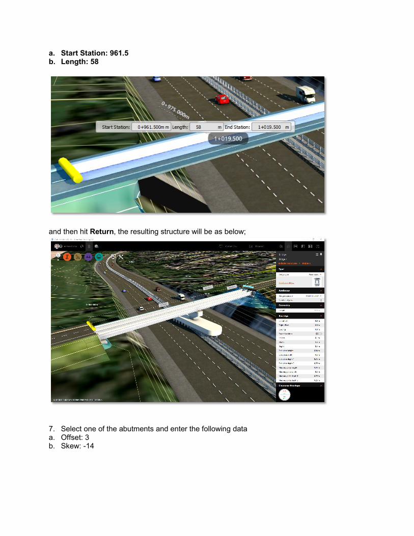
a. Start Station: 961.5 b. Length: 58
and then hit Return, the resulting structure will be as below;
7. Select one of the abutments and enter the following data a. Offset: 3 b. Skew: -14

8. Repeat for the other abutment. 9. Select the central pier and change the Skew to -14. 10. Deselect the bridge by pressing Esc and then select the road, right click and select Road
Assembly > Replace Assembly
11. Choose the ‘Bridge Assembly’ option from the list

12. Then, using the grips, stretch out the orange/blue rectangle to cover the extent of where
you feel the handrailing would start and finish, then press Return.

13. Select the bridge once more, then select one of the girder groups, change the number of girders to 5.
14. Right click on the group and select Apply To... > All Girder Groups.
15. Right click on the bridge and select Component Display and check Deck.

16. Select the deck and change the Continuity value to Deck Only.
17. Next from the Bridges menu select Line Girder Analysis
18. Click Start Analysis in the Line Girder Analysis panel.
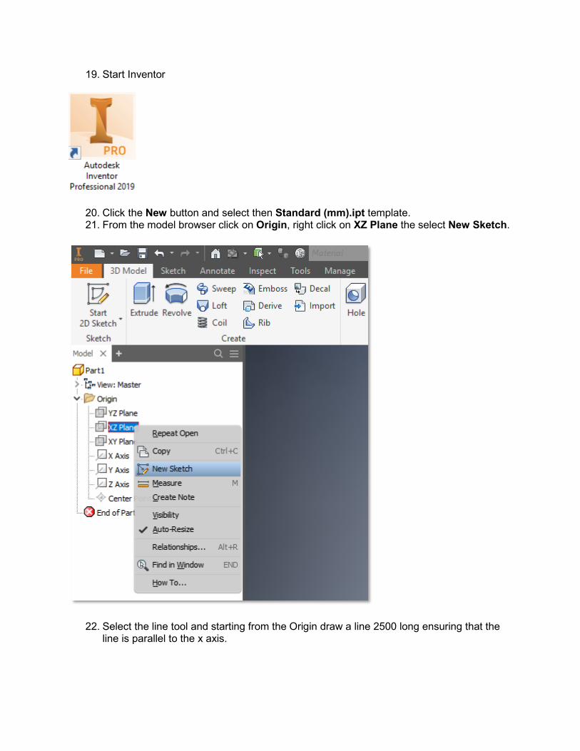
19. Start Inventor
20. Click the New button and select then Standard (mm).ipt template. 21. From the model browser click on Origin, right click on XZ Plane the select New Sketch.
22. Select the line tool and starting from the Origin draw a line 2500 long ensuring that the line is parallel to the x axis.

23. Next draw a line at the rough angle shown with a length of 5000 (you can type the
number in the field)
24. The draw a temporary line down the centre for mirroring.

25. Use the mirror tool from the toolbar to mirror the sloping line to the other side of the Z axis.

26. Now delete the mirror line, the very first 2500 long line and all the dimensions by selecting them and pressing delete.
27. To complete the drawing, we now need to draw a line between the tops of the sloping lines and the bottom of the sloping lines.
28. Click on the dimension style button and select Expression.
29. Use the Dimension tool to add a dimension to the height of the pier with parameter name
as shown (capitalisation is important) Ensure that the dimension line runs from top of the pier top corner to the origin.

30. Then add dimensions to define the width of the pier including parameters as shown;
31. Click Finish Sketch at the end of the toolbar. 32. Rotate the view to show the z axis uppermost.

33. Use the Extrude tool on the toolbar to create a 1000mm symmetrical extrusion with parameter name ‘Thickness’.
34. Click on the Manage tab and select Parameters 35. Tick all checkboxes for Key and Export

36. Then click on the Environments tab and select Infrastructure Part Shape Utilities then Export Template.
37. Under Select Folder, select a suitable file location, perhaps the Desktop and give the file a name, click Export.
38. Close the dialogue box and click Finish Infrastructure. 39. Go back to InfraWorks

40. Open the Style Palette
41. Select the Parametric Models tab and navigate to Bridge > Piers 42. Hit the Plus icon at the bottom of the Style Palette.
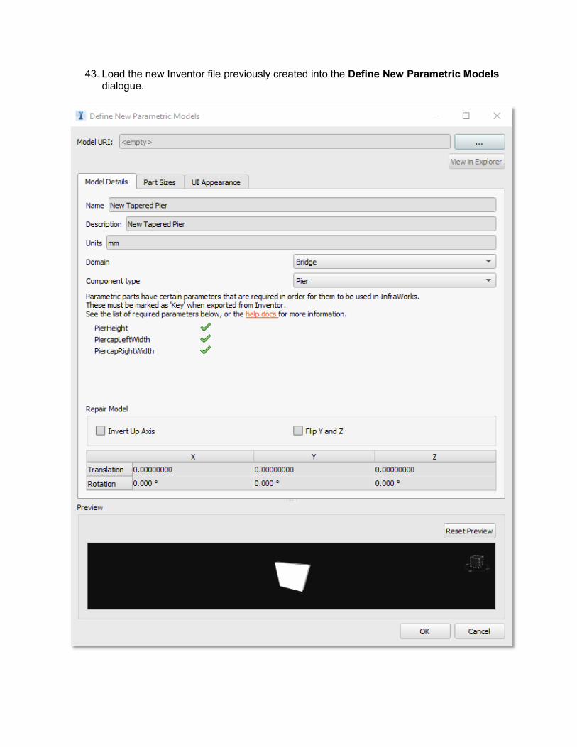
43. Load the new Inventor file previously created into the Define New Parametric Models dialogue.

44. Under the UI Appearance tab untick Visible and Editable for the unnamed parameters.
45. Click OK and accept the default name in the Style Palette and close it. 46. Select the central pier and click on the Type hyperlink in the stack on the right hand
side.

47. Double click on the New Pier that has been newly created.

48. Select the piled foundation and amend the values below; a. Height above ground: -5.0 b. Size based on pile count : On c. Count: Transverse row: 5 d. Pile length: 10 49. Select the new pier and change the Thickness to 1.75m. The model is now complete.
50. Check the analysis results by going back to the Line Girder Analysis icon and selecting
the bridge. 51. Click on one of the girders and select Get Full Report from the Line Girder Analysis
panel and completing purchase (Free).

52. Click on the hyperlink for Girder Design Summary and then Live Load Bending – Strength 1.

53. Open the girder in Structural Bridge Design by clicking on the icon in the Line Girder Analysis panel
54. Close the open windows and select the Design Beams tab. 55. Select the first design beam SB1: Pretensioned Prestressed 56. Click the ‘play’ button to run the design checks.

57. In the beam analysis panel select Transient Load BM1 : [Max +ve] and choose Strength 1.
58. Note the Permissive negative moment jump in capacity, then close the dialogue. 59. Click on Beam Definition in the tree.

60. Choose Reinforcement from the drop-down menu in the definition dialogue.
61. Draw a box to select all the slab reinforcement.

62. Click the Delete Bar button then click OK and close the beam definition dialogue.
63. Click on the green ‘play’ button again and notice the reduction on permissible negative moment capacity.
64. Go back to InfraWorks. 65. Select the bridge, right click and select Send to Revit > Create New and click Create.

66. In Revit hover over one of the road components, right click and select Hide in View >
Category. 67. Repeat with the bridge deck element but choose Elements instead. 68. Under the Manage tab choose Position > Rotate Project North.
69. Choose Align selected line or plane.

70. Then click on one of the lines representing the end of a girder.
71. Click OK and zoom back out. The model should now be oriented as shown.

72. Create section by choosing the Section tool from the toolbar and drawing a horizontal line across the central pier as shown.
73. You should now see this;

74. Deselect the section tool and then double click on the blue section marker to be taken to the new view.

75. Use the same tool to draw a vertical section through this view.
76. Go to the new view by double clicking on the section marker as before.

77. Click on the ‘crop regions’ and use the grips to reduce the size of the cropped view.
78. In Revit click on the 3d View to create the view.

79. Change the appearance of the view by changing Detail Level to Fine and Visual Style to Shaded.
80. The view should look like this;

81. To add rebar switch to Section 2 and click on the pier, which should highlight in blue. Then select Rebar from the ribbon.
82. Click OK, then select shape code M_17 from the shape codes menu, then carefully click inside the pier making sure that the central leg of the bar is against the bottom of the pier, the spacebar will change the orientation of the bar. Then press Esc.

83. You should see something like this;

84. For the current view change the Detail Level to Fine and the Visual Style to Shaded. The view should then look like this.
85. Select the bar then open the View Visibility States in the Properties Panel..you may have to scroll down.
86. Tick both View Unobscured and View as solid for 3d View {3D}.

87. Switch to the 3d view to see the bar. 88. Change the bar diameter by click on type selector and clicking on 22M.

89. To change the bar colour click on Edit Type in the Properties Panel, the click on the Material selector.
90. At the bottom of the Material Browser click on Create New Material.
91. Right click on the New Default Material created and rename to 22M Bar. 92. With the 22M Bar material selected go to the Appearance tab and select an appropriate
colour.

93. Then go to the Graphics tab and check the Use Render Appearance box.
94. Click Apply and OK, then Apply and OK.

95. By deselecting the bar, you will see the new bar with the new material.

96. Select the bar again and then change Layout to Maximum Spacing and 300mm.
97. Go back to Section 2. Select Edit Constraints from the ribbon.

98. Click on the top right blue dot and then enter the value -5000 to reduce the length of the leg.
99. Repeat for the opposite leg, then click Finish in the ribbon. You can then deselect and see the effect in the 3d view.

100. Go back to Section 2, select the pier again, choose Rebar and select shape M_02. 101. Change the Placement Orientation to Perpendicular to Cover in the ribbon.
102. Place a bar close to the central leg of the existing bar.
103. Change the bar to 19M and change the colour as before if desired.

104. Change the Layout to Maximum Spacing and Spacing to 450mm. 105. Select Edit Constraints again, click on the right most bar and use the grips to
drag it to the left to position it.
106. Click on the left most bar constraint and this time type a value of -72.

107. Now select the horizontal line within the bar constraint and change the value to -72.
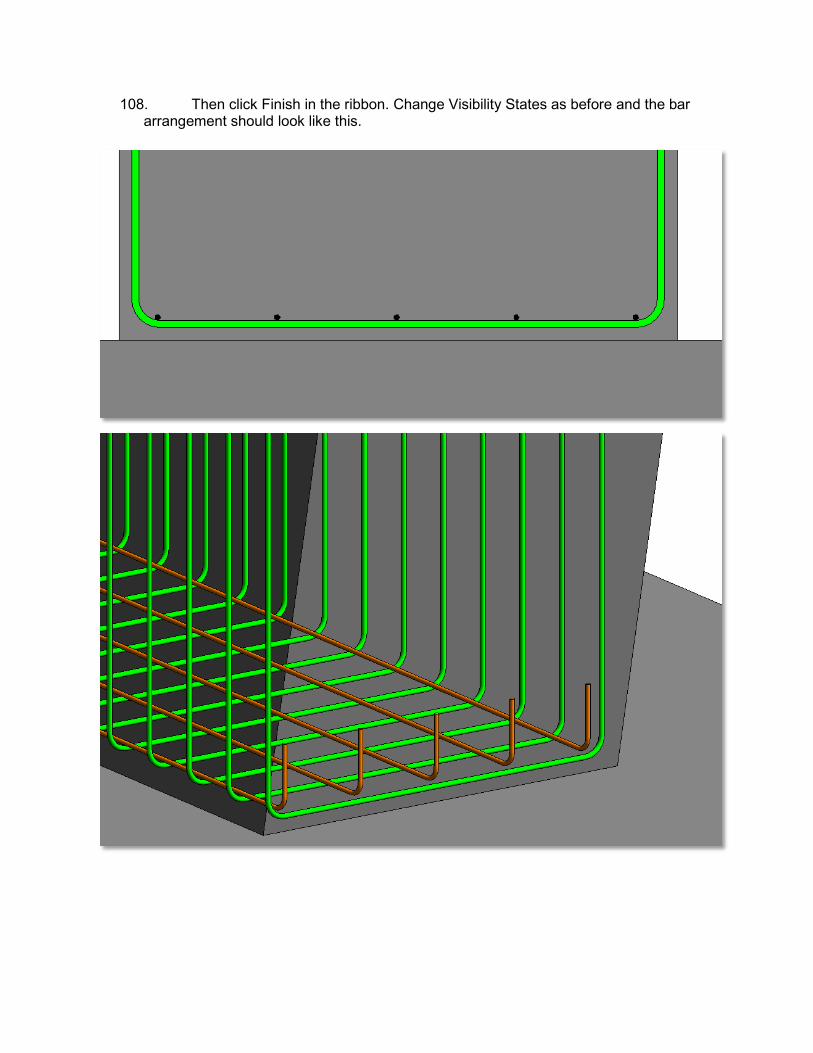
108. Then click Finish in the ribbon. Change Visibility States as before and the bar arrangement should look like this.

109. To schedule the bars right click on Schedules/Quantities in the Project Browser and choose New Schedule/Quantities…
110. Locate Structural Rebar in the list, highlight it and then click OK.

111. Move the required fields from the left-hand list to the right and reorder them as shown;
112. Click on OK to reveal the schedule table.
113. Right click on Sheets in the Project Browser and select A1 metric and click OK.

114. Expand the Schedules tree in the Project Browser and drag the Rebar Schedule onto the sheet and position.
115. Go back to Level 2 view. 116. Select the Section tool and create a new vertical section.

117. Then from the Modify area select Rotate and the choose Place for Centre of rotation.

118. Place the centre of rotation on one of the girder edges, then drag vertically down and click.
119. Then select the edge again, as shown, to rotate the view.

120. Drag the view into place and use the grips to change the coverage so as to replicate the view below;

121. Deselect the view tool then double click the section marker to go to the created view.
122. Go back to Section 1. 123. Click on the U bars and select Show Middle from the presentation area of the ribbon.

124. From the Annotate tab on the ribbon select Multi-Rebar and then Aligned Multi-
rebar annotation. 125. Click on the single U bar and drag the annotation to a convenient location.
126. Go to Section 2. 127. Click on Linear from the Annotate > Dimension tab on the ribbon.

128. Click on the corners of the foundation to generate dimensions and click to position them.

129. Click on the outer rectangle and use the grips to position the Crop appropriately.

130. Hide the crop region.

131. Change the scale to 1:50.
132. Switch to the sheet view and drag the Section 2 onto the sheet and position it.
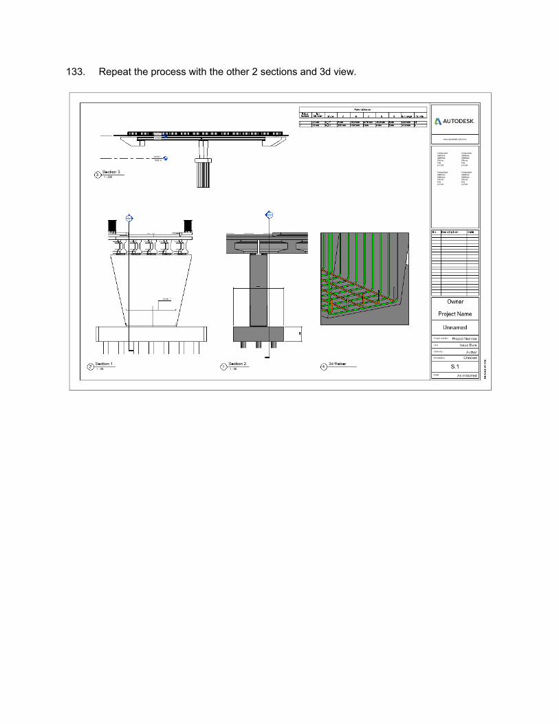
133. Repeat the process with the other 2 sections and 3d view.