CHRYSLER GROUP LLC - Login Page 103... · CHRYSLER GROUP LLC Chrysler Security ... ambient noise...
51
CHRYSLER GROUP LLC Chrysler Security Services Fire Protection Engineering Standards Standard 103 Acceptance testing Issued: 1/88 Revised 1/00 3/01 12/01 06/2003 02/06 09/07 11/10 1/1106/12
Transcript of CHRYSLER GROUP LLC - Login Page 103... · CHRYSLER GROUP LLC Chrysler Security ... ambient noise...
- 1 -
CHRYSLER GROUP LLC
Chrysler Security Services
Fire Protection Engineering Standards
Standard 103
Acceptance testing
Issued: 1/88 Revised 1/00 3/01 12/01 06/2003 02/06 09/07 11/10 1/1106/12
Standard 103 2
Table of Contents
1.0 Introduction
1.1 Purpose
1.2 User
1.3 Authorization
2.0 Definitions
2.1 General
3.0 References
3.1 General
3.2 National Fire Protections Associations Standards and Factory Mutual Data Sheets
3.3 National Fire Protection Association
3.4 Fire Protection Handbook
3.5 Underwriters Laboratories
3.6 Factory Mutual Global
3.7 Industrial Risk Insurers (now known XL)
3.8 Canadian Standards/Codes
3.9 Building Codes
4.0 General
4.1 Introduction
4.2 Authority
4.3 Equipment
4.4 Approvals
5.0 Underground Fire Water Supply Mains Located within Building in Roof Trusses
5.1 Hydrostatic Tests
5.2 Flushing of Underground Connections
5.3 Hydrant Waterflow Tests
6.0 Fire Pump Acceptance tests
6.1 General
6.2 Measurements
6.3 Flow Test Procedure
6.3.1 Electric Motor Driven
6.3.2 Diesel Engine Driven
6.5 Calculations
6.5.1 Diesel Driver
6.6 Power Supply
Standard 103 3
6.6.1 Wiring
6.6.2 Over-current Protection
6.6.2.1 Fire Pump Controller
6.2.2.2 Fire Pump Feeder Circuit
6.6.4 Motors
6.7 Diesel Engine
6.8 Accessories
6.9 Control Panel Functions
6.10 Suction
6.11 Jockey (Pressure Maintenance) Pumps
6.12 Additional Criteria
7.0 Sprinkler System Acceptance tests
7.1 General
7.2 Hydrostatic Tests
7.3 Flushing
7.4 System Waterflow Tests
7.5 Sprinklers and Piping
7.6 Dry Pipe Sprinkler Systems
7.7 Pre-Action/Deluge Systems
8.0 High Speed Water Spray (Deluge) System Acceptance tests
8.1 General
8.2 Hydrostatic Tests
8.3 Flushing
8.4 Optical Detector Systems
8.4.1 Functional Tests
8.5 System Water Flow Tests
8.6 Water Spray Nozzles and Piping
8.7 High Voltage Paint Zones
8.8 Low Voltage Paint Zones
8.9 Electrostatic Hand Held Paint Zones
8.10 Proprietary Products
9.0 Gaseous Agent Acceptance tests (not including carbon dioxide)
9.1 General
9.2 Functional Tests
9.2.1 Systems Operations
9.3 Discharge Tests
10.0 Detection System Acceptance tests
Standard 103 4
10.1 General
10.2 Fire Control Release Panel
10.3 Detectors
10.3.1 Smoke Detectors
10.3.2 Heat Detectors
10.4 Initiating and Annunciating Devices
10.4.1 Manual Pull Stations
10.4.2 Alarm Signaling Appliances
10.4.3 Voice Alarm Systems
10.4.4 Power Supply
10.4.5 Electrically Supervised Circuits
10.4.6 Auxiliary Equipment
10.5 Trouble Shooting
11.0 Carbon Dioxide System Acceptance tests
11.1 General
11.2 High Pressure
11.2.1 High Pressure Storage
11.2.2 Functional Tests
11.2.3 System Operations
11.2.4 Discharge Tests
11.2.5 Resetting the System
11.2.6 Pneumatic Time Delays and Sirens
11.3 Low Pressure
11.3.1 Low Pressure Storage
11.3.2 Extended Discharge
11.3.3 Hand Held Hose Lines
11.3.4 Functional Tests
11.3.5 System Operations
11.3.6 Discharge Tests
11.3.7 Pneumatic Time Delays and Sirens
12.0 Dry/Wet Chemical System Acceptance tests
12.1 General
12.2 Functional Tests
12.3 Bag Tests
12.4 Manual Release
12.5 Test Procedures
13.0 Water Mist Systems

Standard 103 5
1.0 Introduction
1.1 Purpose
The purpose of this Standard is to provide guidelines for the performance of Acceptance tests on Fire
Protection Systems installed at Chrysler Group LLC facilities.
This Standard shall not take the place of, but shall be in addition to Federal, State, Provincial or local fire
safety requirements. The Authority Having Jurisdiction (AHJ) shall also be consulted.
This Standard shall not be construed as detailed design criteria for the installation of new fire
protection equipment or modification of existing fire protection systems, nor shall these Standards
be used in place of equipment manufacturers’ specifications or test procedures. They are general
guidelines, which can be used by qualified Chrysler Group LLC personnel or authorized
representative to assist in conducting Acceptance tests of fire protection systems/equipment. In no
case shall un-qualified persons attempt to use these guidelines in lieu of proper training.
1.2 User
This Standard has been developed for use by Chrysler Security Services and GRC in the performance of
work associated with Acceptance tests on fire protection systems installed at Chrysler Group LLC
facilities.
1.3 Authorization
This Standard is issued by Chrysler Security Services.
Only personnel from Chrysler Security Services shall revise this Standard. Suggestions shall be submitted
to this Department for review and action.
Standard 103 6
2.0 Definitions
2.1 General
For the purpose of this standard, terminology is applied with definitions as follows:
Approved: Acceptable to the “Authority Having Jurisdiction (AHJ)”.
Audible Alarm: A fire alarm device which produces a distinctive sound signal which is heard above the
ambient noise level per NFPA No. 72, “Proprietary Protective Signaling Systems”.
Authority Having Jurisdiction (AHJ): The organization, office or individual responsible for
“approving” equipment, an installation, or a procedure to meet statutory requirements. For insurance
underwriting purposes only, the insurance carrier representative may be the AHJ.
Bete Nozzle: A delivery nozzle used in conjunction with high-speed water spray systems in paint spray
booths.
Bypass Switch: A control device that electrically bypasses normal actuating components and allows the
system to function (by-pass mode) for testing or maintenance.
Cabinet (NEMA-12): The lockable enclosure that houses & protects the electrical control equipment
such as release control panels, power supplies, specialty modules.
Carbon Dioxide: A naturally occurring heavier than air extinguishing agent.
Cla-Valve: The flow control valve that automatically activates the Paint Booth High Speed Water Spray
System as manufactured by Cla-Val Company.
Clean Agent: Electrically non-conducting or gaseous fire extinguishing agent that does not leave a
residue upon evaporation. The word agent as used in this document means clean agent unless otherwise
indicated.
Contractor: The outside party/persons contracted for the design and installation of fire protection
systems.
Corporate: Chrysler Security Services (CSS) or their designated representative(s).
Control Cabinet/Unit: The cabinets that contain detection control units, system release panels and
standby batteries for special systems.
Cross-Tie: Connection between two adjacent sprinkler systems that adds reliability to a sprinkler system
by providing a second water supply (source) in the event of primary water supply shutdown. Cross-Tie
valves are usually 2.5-inch normally closed valves. These valves shall not be locked or monitored.
“Deluge” Sprinkler System: A system employing automatic sprinklers with open orifices attached to a
piping system with a supplemental detection system installed in the same area as the sprinklers.
Actuation of the detection system opens a valve that permits water to flow into the piping system and out
the open sprinklers.
Dip Switch: Switches which can be set manually on a device that affects certain actions. The settings
shall be per Manufacturer’s requirements or as approved by the Chrysler LLC Corporate Fire Prevention
Engineer. All settings shall be recorded on the As-Built drawings
Down Commers: Flexible or rigid plastic tubing that can be connected to a Bete nozzle to direct the
discharge into the water wash. They are utilized to test the operation of a high speed system without
wetting down the automation in the spray zone. Initial tests of all zones must be by discharge through the
Bete nozzles without down commers to ensure proper coverage. Tests must be witnessed and approved
by Corporate and GRC.
Standard 103 7
Dry Contacts: Contacts wired to a terminal block with no applied voltage for the purpose of indicating a
change in status (signal or control wiring).
“Dry” Pipe Sprinkler System: A system employing automatic sprinklers attached to a piping system
containing either pressurized air or nitrogen, the release of which permits the water pressure below the
valve to open the dry pipe valve, allowing water to flow into the piping system and out of the fused
(open) sprinklers. This system is commonly used for below freezing temperature environments. Grid
piping arrangements shall not be permitted for dry pipe system.
ECARO: HFC-125 Gaseous extinguishing agent
EQP: Eagle Quantum Panel as manufactured by Detector Electronics.
FM-200: Great Lakes Chemical trade name for fire suppression agent HFC-227ea.
GRC: Global Risk Consultants- Chrysler Group LLC 3rd
party loss consultants.
High-Speed Water Spray (Deluge) System: A suppression system for the high hazard areas designed to
rapidly detect fire (using infrared optical fire detectors) and subsequently provide water to the protected
area through special nozzles.
Infrared Detection (IR): A device that is responsive to radiant energy outside the range of human vision
(above 7700 Angstroms) to sense the presence of flame as manufactured by a licensed and qualified fire
detection contractor.
Manual Pull Station: A wall mounted device that enables a fire alarm system to be manually activated.
Manual Release Station: A wall mounted device that enables a fire suppression system to be manually
activated.
Pilot Line: The hydraulic line that initiates the functions of the High-Speed Water Spray (Deluge)
Systems.
“Pre-Action” Sprinkler System: A system employing automatic sprinklers attached to a piping system
containing air (pressurized or not) with a supplemental fire detection system installed in the same area as
the sprinklers. Actuation of the detection system opens a valve that permits water to flow into the piping
and out any fused (open) sprinklers. Corporate only approves double mechanical interlocked systems.
Pro-Inert: IG-55 inert gas mixture consisting of 50% argon and 50% nitrogen.
Proprietary Protection Signaling System: A signaling system, which serves properties under one
ownership from a central “on site” constantly attended supervising station.
Special System: A Fire Protection System designed to protect special hazard areas i.e. Carbon Dioxide,
Ecaro, HFC-227ea (FM-200), Water Spray, or Water Mist.
Standard: This Corporate Standard.
STRIKE Button: A manual release device and is located on the face of the mechanical release
mechanism.
Temperature Rating: Predetermined-melting point (temperature) at which the fusible link (metal alloy)
of the sprinkler head fuses (operates). Also, predetermined temperature at which the glass bulb breaks
causing glass bulb sprinkler head to operate.
Ultraviolet Detection (UV): A device that is responsive to radiant energy outside the range of human
vision (below 4,000 Angstroms) to sense the presence of flames as manufactured by a licensed and
qualified fire detection contractor.
Standard 103 8
Ultraviolet/Infrared Detection (UV/IR): A device that uses the ultraviolet and infrared detection
principles to sense the presence of flame (both UV and IR sensors must be activated to release the
suppression agent) as manufactured by a licensed and qualified detection contractor.
G4S Secure Solutions Site Security Manager: The local Plant (Complex) Security Manager
Water Hammer: The effect of pressure rise (pipe rupture) that may accompany a sudden change in the
velocity of the water flowing in a pipe.
“Wet” Pipe Sprinkler System: A system employing automatic sprinklers attached to a piping system
containing water and connected to a water supply so that water discharges immediately from any fused
(open) sprinklers.
Standard 103 9
3.0 References
3.1 General
The following references provide fire protection standards and code requirements that shall be used in
conjunction with the established guidelines of this Standard and a Highly Protected Risk (HPR)
insurance carrier.
3.2 National Fire Protection Association (NFPA) Standards and Factory Mutual (FM) Data Sheets
(Latest editions shall be used)
NFPA 10 & Portable Fire Extinguishers
FM 4-5
NFPA 12 & Installation of Carbon Dioxide Fire Protection Systems
FM 4-11N
NFPA 2001 Clean Agent Fire Extinguishing Systems including HFC-227ea (FM-200), ECARO
etc. Fire Protection Systems
NFPA 13 & Installation of Sprinkler Systems
FM 2-8N & 8-9 (includes protection of various storage arrangements)
NFPA 15 & Water Spray Fixed Systems for Fire Protection
FM 4-1N
NFPA 17 & Dry Chemical Extinguishing Systems
FM 4-10
NFPA 17A Wet Chemical Extinguishing Systems
NFPA 20 & Installation of Centrifugal Fire Pumps
FM 3-7N
NFPA 26 Supervision of Valves Controlling Water Supplies
NFPA 70 National Electric Code
NFPA 72 & Fire Detection and Alarm Systems
FM 5-2 & 5- 5
NFPA 750 Water Mist Fire Protection Systems
3.3 National Fire Protection Association (NFPA)
Fire Protection Systems - Inspection, Test and Maintenance Manual (NFPA)
Industrial Fire Hazards Handbook - NFPA
3.4 Fire Protection Handbook - NFPA
3.5 Underwriters Laboratories (UL), Inc.
3.6 Factory Mutual Global
Approval Guides
Data Sheets
Standard 103 10
3.7 Industrial Risk Insurers (XL)
Interpretive Guides
3.8 Canadian Standards/Codes
Canadian Standards/Codes associated with items covered in this Standard shall be adhered to by
Canadian operations where they supersede the references listed above.
3.9 Building Codes
BOCA Basic/National Building Code
Uniform Building Code (UBC)
Southern Building Code (SBC)
International Fire Code
International Building Code
These codes shall be applied where they have been adopted as law by a particular state government or
authority and where they supersede the reference above.
Standard 103 11
4.0 General
4.1 Introduction
This Standard is intended to provide guidelines for “Acceptance testing” of fire protection systems.
Fire suppression, detection, and alarms systems are provided to act in the event of a fire. Periodic
inspection, testing, and maintenance of these systems are conducted to assure their state of readiness.
When these systems are called upon to function, an emergency condition exists and they must work
properly.
In addition to these periodic tests, initial Acceptance testing of new systems are conducted to assure that
the systems are properly installed and operating properly at the time of installation. This Standard
provides guidance on initial acceptance testing of fire protection systems. This Standard may also be
used as a reference for inspection, subsequent testing and maintenance.
The information provided herein is generic in nature with the exception of High-Speed Water Spray
systems. Specific information for particular equipment or systems shall be obtained from the
manufacturer.
Test forms for Acceptance tests are provided at the end of each section and shall be used or referenced
when conducting or observing Acceptance test procedures. Test forms showing satisfactory test results
(provided by the installing contractor) and record drawings shall be obtained and maintained for each
Acceptance test that is conducted by assigned Corporate Fire Specialist.
4.2 Authority
Acceptance tests shall be performed on all newly installed equipment/systems in accordance with this
Standard.
Testing of all fire protection systems shall be performed in accordance with applicable Standards and
Authority Having Jurisdiction (AHJ) requirements.
Acceptance test shall be coordinated with the following:
- Corporate
- Site Contract Security Manager
- Installing Contractor
- Third Party Loss Consultant (GRC)
- AHJ
Chrysler Security Services, the Authority Having Jurisdiction and all other parties required to witness
and Acceptance test shall be apprised of a test date at least five “working” days before a test is to be
performed.
Equipment and installation shall be in conformance with accepted system design drawings, associated
calculations, applicable codes, and this Standard.
4.3 Equipment
Personnel from Corporate and GRC shall approve all fire protection equipment installed in accordance
with this Standard.
All equipment in accordance with this specification shall be Underwriters Laboratories (UL) listed or
Factory Mutual (FM) approved and/or equivalent as determined by Corporate.
Once a manufacturer’s equipment is selected for use in accordance with this Standard, the same
manufacturer’s equipment shall be used to the extent possible to supply compatible equipment for the
specific fire protection systems throughout the plant.
Standard 103 12
4.4 Approvals
As of November 1, 2005 Chrysler Group LLC fire protection engineering services are provided by
Global Risk Consulting (GRC).
Approval is required from GRC and Corporate for design of new buildings, additions, or
renovations/changes that are performed in accordance with this Standard. Approval from GRC shall be
in the form of a formal letter addressed to the contractor who submitted the plans.
For approval purposes, paper copies of all concept drawings, construction drawings, shop drawings,
acceptance test certificates, system impairment notices, and system modifications shall be submitted to:
- Corporate Fire Protection Engineer (1 paper copy)
Chrysler Security Services
CIMS 485-01-52
- The Technical Service Office for GRC listed below: (3 paper copies minimum)
Mr. James Faitel
Senior Consultant
Global Risk Consultants
14058 Edgewood Street
Livonia, Michigan 48154-5334
(734) 513-5070 phone
(313) 268-2965 mobile
(734) 513-7383 fax
e-mail: [email protected]
- Other individuals and/or companies as directed by the Corporate Fire Protection Engineer
THE 90% DESIGN DRAWINGS SHALL BE REVIEWED BY CORPORATE FIRE, PLANTS
SECURITY, PLANT SECURITY MANAGER AND THE LOSS PREVENTION CONSULTING
COMPANY PRIOR TO THE START OF THE JOB.
Requirements that are referenced in this Standard shall be incorporated into contract specifications for all
work/projects.
4.5 Testing
Acceptance tests shall be performed on all newly installed or modified equipment/systems in accordance
with this Standard. Renovations or changes to a fire protection system may require that an acceptance test
be performed.
Acceptance testing shall be coordinated by the General Contractor after being notified by the installing
contractor that the system is ready for testing.
It is recommended that all systems be pre-tested by the Contractor prior to contacting Chrysler
Group LLC for the formal acceptance test. Chrysler Group LLC reserves the right to charge the
contractor the expenses associated with a retest, if no pre-testing is done.
Standard 103 13
The following personnel shall be notified of the test by the General Contractor at least 5 days before the
test:
Chrysler Security Services
Site Contract Security Manager
Third Party Loss Consultants (GRC)
Local Plant Engineering
AHJ
Requirements that are referenced in this Standard shall be incorporated into contract specifications for all
work/projects.
Standard 103 14
5.0 Underground Fire Water Supply Mains and Mains
Located within Buildings in Roof Trusses
5.1 Hydrostatic Tests
All new piping, including underground piping and fire department connections, shall be hydro-statically
tested at not less than 200 PSI (13.8 bars) for two hours. When the maximum pressure in the system is
greater than 150 PSI (10.3 bars), the test pressure shall be 50 PSI (3.4 bars) above the maximum system
pressure. The test pressure shall be read at a calibrated gauge installed at the lowest elevation of the
system or portion of the system being tested.
For any interior over-head supply mains approved by Corporate Fire Prevention Engineer,
hydrostatic tests shall be performed based upon the same testing criteria.
No visible leakage shall be noted from the sprinkler piping. The amount of leakage for underground
piping shall not exceed two quarts (1.89 liters) per hour per 100 gaskets or joints. This permissible
leakage is not respective of (not directly proportional to) pipe diameter. The amount of leakage shall be
measured by pumping from a calibrated container to maintain required pressure during the two-hour test.
The amount of allowable leakage for valves is one fluid ounce per inch valve diameter per hour (30
milliliters) for each valve isolating the tested pipe section.
Hydrostatic testing of underground piping shall be performed before the trench is completely back-filled.
Piping shall be covered between joints to hold the piping in place. Joints, however, shall be left un-
covered so they can be observed for leakage during the test. When test “blanks” are used to isolate a
portion of the system, only self-indicating types shall be used. Each blank, if used, shall be inventoried
so that they can be totally removed from the system upon completion of testing.
Hydrostatic testing of sprinkler system installations of less than 20 heads do not require
hydrostatic testing. Any visual leakage requires immediate repair.
5.2 Flushing of Underground Connections
All underground supply mains and lead-in connections shall be flushed to remove foreign materials
before connection is made to sprinkler piping. Flushing shall continue for a minimum of ten (10)
minutes. After ten (10) minutes, if the water is still not clear, continue flushing until water is clear. Care
shall be exercised during the flushing operation to assure that water flow will adequately drain without
producing damage to surroundings.
Flow rates, in accordance with latest edition of NFPA No. 13 shall be used.
Flow Rate Required to Produce a Velocity of 10-fps (3 m/s) in pipes
Pipe Size (in inches) Pipe Size (mm) Gallons/Minute Liters/Minute
4 102 390 1476
6 152 880 3331
8 203 1560 5905
10 254 2440 9235
12 305 3520 13323
Standard 103 15
A representative from Corporate and GRC must be present for all system flushing
5.3 Hydrant Waterflow Tests
Flow tests shall be conducted for water supply systems to assure that materials and equipment are
installed properly and to assure that all valves are in the open position.
For gravity fed and pressure tanks, this test consists of opening a two-inch main drain at the tank or
sprinkler system. Record both the static pressure (no flow condition) and the full flow pressure.
Compare these pressures with design pressures. If full flow pressures are significantly lower, check all
valves between the water supply and the test point to assure that they are fully open.
For ground or underground storage tanks, the flow test is conducted in conjunction with fire pump flow
tests.
Site underground fire protection water main tests are accomplished in conjunction with hydrant flow
tests.
The local water department shall be notified, if applicable, to identify peak water demand times so water
flow tests can be performed at or near these times.
The following equipment is required for hydrant flow tests:
- Pitot tube with calibrated pressure gauge
- Hydrant cap with calibrated gauge
- Ruler
- Hydrant wrench
- Hydraulic Calculations Table
To perform a flow test, two fire hydrants shall be used. The fire hydrant closest to the building that
requires sprinkler protection is known as the “pressure” hydrant. The next closest hydrant on the down-
stream side of the water system is known as the “flow” hydrant.
Determine static pressure in the water supply system as follows:
- Remove a hydrant cap from the pressure hydrant and tighten any other hydrant caps.
- Open the operating nut to flush away any sediment.
- Close the hydrant.
- Replace the hydrant cap with a pressure gauge.
- Open the bleeder petcock.
- Open fire hydrant fully by turning the operating nut.
- When a steady stream of water flows from the air bleeder petcock, all air has been removed
from the fire hydrant.
- Close the petcock.
- Record the pressure indicated on the gauge. This pressure is known as the “static” pressure.
When water is withdrawn from a water main during a flow test, the “static” pressure drops to a lower
pressure that is known as the “residual” flow pressure. For accurate results, enough water must flow
from the flow hydrant (or hydrants) so that the “residual” pressure is 50% to 75% of the “static” pressure.
The hydrant must discharge a solid stream of water free of voids, since the Pitot gauge measures the
velocity pressure. Velocity pressure is not uniform if the water stream is not reasonably uniform.
Pitot pressure is the velocity pressure of the flowing water stream. Velocity pressures can be converted
into water discharge rates (to be shown later in this section). Pitot pressure is determined by inserting the
tip of the Pitot tube blade squarely into the center of the flowing stream of water. To determine
“residual” and Pitot pressures, perform the following:
- Remove one or more of the hydrant caps from the “flow” hydrant.
- Tighten any hydrant caps not being used.
- Measure the inside diameter of the “flow” hydrant’s butt (flowing outlet) or butts to within 1/16
of an inch and record the measurements on a test results form.

Standard 103 16
- Determine and record the hydrant’s coefficient by feeling the inner edge where the hydrant butt
(outlet) connects to the hydrant barrel.
- If the inner edge (or joint) is rounded, the coefficient is a 0.80; if the inner edge (or joint) is
square, the coefficient is 0.70; if the inner edge (or joint) is square and extends into the hydrant
barrel, the coefficient is 0.60.
- For variations, determine a coefficient based on interpolation of the given parameters listed
above.
NOTE: The coefficients listed above are based upon water flow test parameters from Factory Mutual.
The coefficient used to develop water flow test results must be listed on the test result forms. If any
questions, contact the Corporate Security and the Regional Fire Specialist.
- Open the fire hydrant fully by turning the operating nut.
- Flow the hydrant until it is flushed and a clear stream is observed.
- After the flow has stabilized, insert the tip of the Pitot tube blade squarely into the center of the
water stream. This is equal to one-half of the diameter of the hydrant opening. If water is not
discharging in a solid stream, close the fire hydrant and attach a smaller diameter solid stream
nozzle to the hydrant butt (outlet). Re-open the fire hydrant and perform the Pitot reading.
- Record the Pitot pressure reading(s) for each water streams for a given opening of a “flow”
hydrant. Record each Pitot reading for each hydrant butt (outlet) on the test result form.
- With the “flow” fire hydrant still in the wide open position, return to the “pressure” hydrant to
read and record the pressure indicated on the cap gauge. This is the “residual” pressure for the
given flow test.
- Close each fire hydrant slowly to prevent “water hammer”.
- Listen for noise of draining water to make sure that each fire hydrant is draining properly.
- Another method to be certain that a fire hydrant is draining properly is to close the hydrant with
only one 2-1/2 inch butt (outlet) open. Place the palm of your hand over the hydrant butt and
feel if suction is being created. Suction would mean that the fire hydrant is draining properly.
NOTE: In areas subject to freezing weather conditions, it is critical that any fire hydrant flowed be
examined and properly drained prior to freezing weather condition. If a fire hydrant is not designed to be
self-draining, a flexible hose and suction pump shall be used to remove any excessive water from the
hydrant barrel.
- Remove the hydrant cap with gauge from the hydrant butt and replace all fire hydrant caps.
- Calculate the actual water flow (in GPM’s) measured by the Pitot tube pressure reading(s) by
using the following formula:
Q = 29.83 x C x d2 x the square root of p; where:
Q = flow in gallons per minute (GPM)
C = hydrant coefficient
d = diameter of “flow” hydrant butt (outlet) in inches
p = pressure measured on Pitot tube (PSI)
Using hydraulic graph paper. This is also known as semi-exponential graph paper; two points (or more)
can be plotted:
- “static” pressure at zero flow
- corresponding pressure(s) at actual flow(s)
A straight line through these points indicates the amount of water available at a given pressure. The
graph (shown above) accounts for flows from 1 to 20 gallons per minute. The numbers (figures), on the
bottom of the graph, can be multiplied by a common number. Therefore, any test can be recorded. For
example, multiply 16 GPM by 100 to equal 1,600 GPM. The recording pressure on the vertical scale can
be multiplied in the same manner.
A “Contractor’s Material and Test Certificate” for Underground Piping shall be filled-out and submitted
by the contractor installing any underground piping. It is filled out upon completion of the installation
and tests.
Standard 103 17
6.0 Fire Pump Acceptance tests
6.1 General
Acceptance tests shall be performed for all new, re-built or re-located fire pump installations. The
purpose of an acceptance test is to:
- Determine that the fire pump will perform in accordance with or in excess of the manufacturer’s
certified characteristic curve.
- Determine that the installation is in accordance with the intent of NFPA No. 20 and all design
drawings and specifications.
- Make certain the fire pump will operate properly when needed.
- Determine that the supplemental features operate as follows:
- Power supply (electricity, fuel)
- Controllers
- Drivers (motors, engines)
- Accessories (relief valves, priming sources, flexible couplings, alarms, interlocks)
- Suction supplies
- Fire Pump House (construction, heat, lighting, access, ventilation, sprinkler protection,
drainage etc.)
Manufacturer’s procedure manuals and latest edition of NFPA No. 20 shall be reviewed prior to each
test.
The fire pump manufacturer’s representative in conjunction with the installing contractor is responsible
for conducting the acceptance test.
Acceptance tests shall not be conducted until a representative of the fire pump manufacturer has
inspected and functionally tested the installation and has provided a certified shop test characteristic
curve for the specific fire pump to GRC.
Equipment shall be inspected to determine compliance with “as-built” drawings and specifications.
Deviations shall be discussed with the installing contractor and arrangements for correction shall be
made.
Discrepancies that may affect the test shall be corrected prior to testing.
Fire pump results shall be compared step-by-step with the certified fire pump curve during the test and
discrepancies noted.
Owner representatives shall be informally advised of the fire pump test results when the test is
performed. Formal acceptance shall be given “in-writing” by the installing contractor and GRC after all
parties are satisfied with the test results.
Sprinklers shall be installed in the fire pump house when a diesel driver is utilized.
6.2 Measurements
Fire pump speed shall be measured with an accurate tachometer.
If a contact-type speed indicator is used, a plug or cap is removed from the end of the fire pump casing so
that the speed indicator can contact the end of the fire pump shaft. Any oil or grease on the end of the
shaft shall be removed before the speed device is inserted.
When using a revolution-counter (for fire pumps 2,500 RPM and over) take a reading for two minutes
and divide by two to determine the one-minute measurement. This minimizes starting and stopping
timing errors.
Standard 103 18
If an installed flow meter is used for testing it must be calibrated prior to the test by a calibration
certified company with records for review. Calibration of the meter must be done annually prior
to the annual flow test. If test results vary from previous years then a flow test from the test header
MUST BE DONE
Calibrated pressure gauges shall be used during the test and shall be checked against the gauges that are
installed on the fire pump.
Most suction gauges are of the compound type and can be easily checked for accuracy using positive
pressure.
With open-suction conditions (ponds, rivers, etc.), the actual static-lift distance shall be measured and
compared with the vacuum reading on the gauge when the fire pump is operating under shut-off
conditions.
Test headers are provided for fire pump tests. A separate 2½ inch outlet is required for every 250 GPM
rating of the fire pump. Lengths of 2-1/2 inch hose with straight bore nozzles (Underwriters’ Play Pipes)
are attached and firmly supported. “Hose Monster” type testing equipment is approved for fire pump
testing
It may be feasible to attach the straight bore nozzle directly to each outlet of the test header if water
damage can be prevented.
Water flow (GPM) is determined by the formula:
Q = 29.83 x C x d2 x the square root of p; where:
Q = flow in gallons per minute (GPM)
C = hydrant coefficient
d = diameter of “flow” hydrant butt (outlet) in inches
p = pressure measured on Pitot tube (PSI)
Discharge outlets on the test header shall be opened so that water is discharged at various flows and
pressures. The test determines the fire pump’s capability to discharge at no flow @ approximately 140%
rated pressure (“churn” point), 50% of rated flow, 100% of rated flow @ 100% rated pressure, 125% of
rated flow, and 150% of rated flow @ 65% rated pressure. For example, a 500 GPM fire pump would be
tested at five individual points – 0, 250, 500, 625, and 750 GPM. To do this, the gauges on the intake
and discharge sides of the fire pump are observed and Pitot readings taken at the discharge nozzles.
When a flow reaches the desired percentage of the rated flow, the Pitot pressure, size of outlet, outlet
coefficient, fire pump intake pressure, fire pump outlet pressure, and fire pump speed are recorded.
These tests are repeated and recorded for each of the flows. Results of the tests are plotted on a special
graph commonly known as N1.85
paper and compared with the manufacturer’s fire pump test curve and
the requirements of NFPA No. 20, “Standard for the Installation of Centrifugal Fire Pumps.”
6.3 Flow Test Procedure
6.3.1 Electric Motor Driven
Flow tests shall be conducted from the fire pump test header with the discharge valve to the site
underground fire main piping being closed. This arrangement will prevent unwanted conditions such as
blowing out of the pipe in the site underground fire main (water hammer).
Should a fire main pipe break, impairment procedures shall be followed in accordance with insurance
company policy and Corporate Standards.
Flow is measured through use of straight bore nozzles (Underwriter Play Pipes) and a pitot tube.
Standard 103 19
“Hose Monster” type testing equipment is approved for fire pump testing.
Hose used during the test shall be capped and subjected to “churn” pressure with the hose valve open
only enough to allow water to fill the hose.
This will ensure the integrity of the hose during the test. Secure fire hose so that the nozzles cannot work
loose. Nozzle shall be aimed so that they do not cause damage to property.
Water flow, from each nozzle, shall be measured using a pitot tube, and GPM calculated using charted
flows.
Discharge and suction pressure for a horizontal fire pump shall be read at gauges located at the centerline
of the fire pump on the casing.
Vertical turbine fire pump discharge pressure is normally recorded from a gauge located at the discharge
head fitting.
6.3.2 Diesel Engine Driven
With variable speed driver (diesel engine), the preferred test method is to “run” the fire pump under
governor control. When this method is used, each flow and pressure measurement must be corrected
mathematically to the rated speed. The governor shall be observed and adjusted as necessary to provide
rated fire pump speed at the maximum fire pump “load” as shown on the manufacturer’s certified test
curve.
The flow test shall start at a “churn” (no flow) measurement. The circulation relief valve shall be
adjusted for no flow at shutoff to ensure that no water is lost prior to measurement.
A small amount of water will flow when engine driven fire pumps take cooling water from the fire pump
discharge. This amount is insignificant in that it cannot noticeably affect the pressure gauge reading.
Leakage is accounted for by approximating flow to be 0.20 GPM per horsepower or by measuring flow
into a container.
Flow tests shall be conducted from the fire pump test header with the discharge valve to the site
underground fire main piping being closed. This arrangement will prevent unwanted conditions such as
blowing out of the pipe in the site underground fire main (water hammer).
Should a fire main pipe break, impairment procedures shall be followed in accordance with Chrysler
Security Services policy.
Flow is measured through use of straight bore nozzles (Underwriter Play Pipes) and a pitot tube.
“Hose Monster” type testing equipment is approved for fire pump testing
Hose used during the test shall be capped and subjected to “churn” pressure with the hose valve open
only enough to allow water to fill the hose. This will ensure the integrity of the hose during the test.
Secure fire hose so that the nozzles cannot work loose.
Nozzle shall be aimed so that they do not cause damage to property.
Water flow, from each nozzle, shall be measured using a pitot tube, and GPM calculated using charted
flows.
Discharge and suction pressure for a horizontal fire pump shall be read at gauges located at the centerline
of the fire pump on the casing.
Vertical turbine fire pump discharge pressure is normally recorded from a gauge located at the discharge
head fitting.

Standard 103 20
6.5 Calculations
6.5.1 Diesel Driver
Flow and pressure readings for the diesel engine driven fire pumps shall be corrected mathematically to
the fire pump’s nameplate speed conditions.
Flow is proportional to the speed, and pressure is proportional to the speed squared.
rated speed
Corrected Flow = measured flow x (measured speed)
(rated speed)2
Corrected net Pressure = measured net pressure x (measured speed)2
For horizontal fire pumps where Vh is the change in velocity head expressed in PSI - Vh is determined
using the following equation:
Measured Net Pressure = Discharge Pressure – Suction Pressure + Vh
.001123 (measured GPM)2
Vh = (suction inlet diameter)4 - (discharge outlet diameter)
4
Note: If fire pump discharge and suction flange openings (point of gauge attachment) are of the same
size, there will be no change in velocity head since the velocity is the same in each. If the fire pump
discharge flange opening is smaller than the fire pump suction flange opening, there will be an increase
in the velocity energy as the water passes through the fire pump. This change must be credited to the fire
pump.
Standard 103 21
6.5.2 Vertical Turbine Fire Pump
The design or nameplate pressure is calculated using the elevation distance to the water level; there is no
suction gauge. The discharge gauge is located on the discharge side of the fire pump casing. Since this
gauge is not at water level, the pressure lost due to elevation of the gauge must be added to the gauge
reading to arrive at the true or net pressure. Friction loss between the water level and the discharge
gauge is generally negligible. The formula for the vertical turbine fire pump becomes:
Measured Net Pressure = Discharge Pressure + EL + Vh
EL is the Elevation difference between water level and the centerline of the discharge gauge.
When a vertical turbine fire pump takes suction from a pressurized water main, the net pressure shall be
calculated as it is for a horizontal fire pump and the necessary adjustment shall be made for elevation
differences.
6.6 Power Supply
6.6.1 Wiring
Wiring from the source of the electric power shall be dependable and so arranged that it will not be
interrupted or damaged by fire, lightning, or other destructive forces. Refer to NFPA No. 20 or FM D.S.
3-7N regarding suitable wiring arrangement. Wiring details shall be acceptable to GRC.
6.6.2 Over-current Protection
6.6.2.1 Fire Pump Controller
The circuit breaker shall meet the following specifications:
The continuous current rating shall be at least 115 percent of the fire pump motor’s rated full-load
current as shown on the nameplate of the over-current device.
The interrupting capacity shall be equal to or greater than the maximum fault-current possible at the
location of the breaker, as determined by the manufacturer.
Size of the transformer, size and length of the cables supplying power to the circuit breaker and the
amount of power available from the utility determine the fault current flow which the circuit breaker must
be able to interrupt.
The factory-sealed instantaneous trip setting shall be at least 12 times the full-load current rating of the
fire pump motor.
This setting is shown on the nameplate of the over-current device. An instantaneous trip setting as high
as this is necessary because of the “spike” or current surge when the motor attempts to start at the peak of
the current cycle.
Circuit breaker trip setting shall be at least 12 times the “over-current” trip-coil rating of the breaker.
The overload trip mechanism shall be set at 300 percent of the motor full-load current. At locked-rotor
current (about 600 percent of the motor full-load current), the circuit breaker must trip in 8 to 20
seconds. This setting is shown on the nameplate of the over-current device.
Direct current motors shall have circuit breakers that will trip instantaneously at or above 400 percent of
the motor full-load current. This protects the motor insulation against heat generated in an extended
lock-rotor condition.
Standard 103 22
6.6.2.2 Fire Pump Feeder Circuit
Fuses, if used, shall have:
A continuous current rating equal to or greater than the sum of the full-load current of the fire pump
room accessories and the rated lock-rotor current(s) of the fire pump motor(s) (600 percent of the full-
load current) if they operate off the same feed.
Interrupting capacity equal to or greater than the maximum fault current possible at the location of the
fuses as determined by a qualified electrical engineer.
A locked panel door to ensure non-tampering by unauthorized persons.
A circuit breaker, if used, shall have:
The breaker shall have an instantaneous trip only. It shall not have an “over-load” trip mechanism.
The continuous current rating equal to or greater than the sum of the full-load current of the fire pump
room accessories and the rated lock-rotor current(s) of the fire pump motor(s) (600 percent of the full-
load current) if they operate off the same feed.
Interrupting capacity equal to or greater than the maximum fault current possible at the location of the
breaker as determined by a qualified electrical engineer.
The instantaneous trip setting shall be at least 12 times the full load current rating of the fire pump motor.
An instantaneous trip setting as high as this is necessary because “spikes” or current surges may occur if
the motor(s) attempts to start at the peak of the current cycle. This is considerably above the calculated
trip setting, but is accessible because it is intended for short circuit protection on the feeder conductors
where a short circuit can draw current in excess of this value. This setting is shown on the nameplate of
the over-current device.
A locked panel door to ensure non-tampering by unauthorized persons.
6.6.4 Motors
Motors shall “run” (operate) smoothly without excessive vibration.
Voltage shall not exceed 110 percent of the motor’s rated voltage and shall not drop more than 5 percent
below the motor’s rated voltage when the fire pumps are being driven at rated conditions while the
conductors between the power station(s) and motors are carrying peak loads. NFPA #20 requires the
provision for amperage and voltage readings to be taken during testing.
Motors shall be started and shut-off 10 times (minimum) in succession for both manual and automatic
operation. The motor and control equipment shall not overheat during the test.
When operating at peak electrical load (about 140 to 150 percent of the flow capacity) the fire pump
shall be shut down and then restarted. The “in-rush” motor current will be the same as before, but be of
greater duration since the fire pump will come up to speed more slowly. The motor shall not overheat or
open circuit breakers during this test.
Motors used above an altitude of 3,300 feet shall be de-rated according to altitude. Consult the
manufacturer for information.

Standard 103 23
6.7 Diesel Engine
The flow of the fire pump may not adequately test the engine. After the fire pump has been flow-tested
satisfactorily, water flow shall be adjusted for peak power requirement (about 140 to 150 percent
capacity), and allowed to run for 15 to 20 minutes to demonstrate that the engine will not overheat under
this condition. Cooling water shall be arranged to discharge to a safe location with no possibility of
flooding the fire pump room even during a power failure.
After the engine has operated for approximately 30 minutes (for the flow test), it shall be started and
stopped 10 times in succession to test both manual and automatic operation.
The engine-speed governor shall be adjusted and secured to maintain fire pump load, or approximately
140 to 150 percent of the rated fire pump capacity. The governor must control the speed with no more
than a 10 percent variation between maximum fire pump load and shut-off condition (churn).
The over-speed governor shall be set at approximately 120 percent of the rated fire pump speed. When
possible, check this setting by operating the engine above rated speed. It is important that the setting is
high enough to prevent shutdown of the engine during start-up. This device must be reset manually after
each over-speed shutdown.
Diesel engines shall be wired to not shut down automatically when they over-heat or when the lubricating
oil pressure is low. Warning alarms indicating these conditions shall be provided.
Diesel fuel shall be stored inside to keep fuel from thickening in cold weather, and to protect the fuel
tank in which it is stored against physical damage. In multiple fire pump installations, each fire pump
shall have a separate fuel tank and fuel supply line.
Fuel supply tanks shall have a capacity at least equal to one (1) gallon per horsepower, plus five (5)
percent for volume expansion and shall be dedicated to the fire pump diesel engine.
6.8 Accessories
The installation and setting of the main relief valve shall conform to NFPA #20. To prevent overheating,
a circulation relief valve adjusted to open at approximately 5 PSI below the minimum shut-off (churn)
pressure, or suction at the lowest point, is needed to provide a small water flow through the fire pump
when it is operating with no other discharge.
A horizontal fire pump and driver require a flexible coupling and safety guard in the shaft between them
to compensate for any slight misalignment and to provide shaft-end clearance to compensate for heat
induced shaft expansion. This is usually a simple loose pin coupling.
NOTE: It is very important that this coupling be properly aligned prior to beginning any acceptance test.
The fire pump shall be subject to at least one full hour of continuous operation to prove that bearings and
packing boxes are in good condition, and will not over-heat. Packing glands on horizontal fire pump
shafts shall be adjusted so that water drips freely or “runs” in a thin stream to cool, lubricate and provide
an air seal.
A fire pump shall not be operated when dry or unprimed, nor shall it be allowed to “churn” for more than
three to five minutes without water circulation. The closely fitted seal rings can overheat, and cause
damage to the fire pump.
Other accessories include:
- Suction and discharge pressure gauges
- Flanged type waste cone
- Capacity nameplate
Standard 103 24
6.9 Control Panel Functions
All control panel functions shall be tested. If the fire pump house is not constantly attended, alarms shall
be transmitted to the central supervision station (proprietary signaling system).
Typical alarms indicate:
Fire pump “running” (started)
Loss of operating electric power
Phase reversal on line side of the motor
Low fuel supply
Controller main switch in “off” or “manual” position
Low temperature in fire pump room
Suction supply water level below normal
Engine trouble such as:
a) Low lubricating oil pressure
b) High engine temperature
c) Failure of engine to start (over-crank)
d) Engine over-speed shutdown
e) High water temperature
f) Battery failure
If these alarms have a common audible signal, each condition shall be visually shown (individually) at
the fire pump controller, and at the Plant’s proprietary alarm panel.
6.10 Suction
Multiple fire pumps taking suction from a single water source shall be operated simultaneously at
maximum flow to verify that the fill pipes are unobstructed, and properly sized to maintain an adequate
water level.
6.11 Jockey (Pressure Maintenance) Pumps
Jockey pumps are used to maintain a uniformly high pressure on the fire protection system to:
- Assure high pressure on initially fused sprinklers.
- Permit the fire pump to start at a high system pressure so that water hammer will be less likely
to occur.
- Avoid frequent and unnecessary starting of fire pumps because of minor fluctuations in the
system pressure.
- Prevent false alarms caused by surges in the public water supply.
Jockey pumps can be used for applications as small as an individual sprinkler system, or for an entire
underground system. The jockey pump shall be rated (capacity and pressure) to provide a flow
approximately twice the rate of anticipated or experienced leakage in the system at the pressure
corresponding to the “off” setting of the controller for the fire pump. Leakage at a specified pressure can
be measured by pumping water into the system through a meter, or from a container of known volume.
The jockey pump and controls arrangement shall be designed in accordance with NFPA #20 and FM
D.S. 3-7N
Jockey pumps may be of either the centrifugal or positive displacement type.
To prevent over-pressurizing and damage the system, the maximum possible discharge pressure of the
jockey pump shall be less than the pressure rating of the system. A positive-displacement jockey pump
Standard 103 25
shall have a relief valve bypass (internal or external) that is set to prevent a pressure in excess of the
system rating.
6.12 Additional Criteria
Pressure shall not exceed the pressure rating of the system (usually 150 - 175 PSI).
The fire pump shall be arranged to start at a pressure close to its maximum possible discharge pressure
(as installed) to avoid water hammer.
The fire pump shall be arranged to start before sprinkler system pressure drops below designed operating
pressure.
The fire pump shall be arranged for automatic start and manual stop.
The jockey pump shall be arranged to start at a pressure above the starting pressure setting of the fire
pump (approximately 10-PSI) to prevent false starts of the fire pump.
A pressure differential between the “start” and “stop” settings of the jockey pump (10 to 15 PSI) is
required to prevent unwanted fire pump motor/engine starts.
The controller for the jockey pump shall incorporate a running-period timer (set for approximately 1
minute per 10 horsepower) to allow for cooling of the electric motors, unless it can be determined that
the normal “running” cycle will equal or exceed that period.
Weekly “churn” criteria for fire pumps is:
Ten (10) minutes – electric motor driven
Thirty (30) minutes – diesel engine driven
Fire pumps shall not be placed on a timer to start or stop.

Standard 103 26
Possible causes of fire pump trouble are listed within NFPA No. 20 when troubleshooting a fire pump
installation during an Acceptance test.
The final fire pump and jockey pump settings shall be determined by Corporate and GRC.
Standard 103 27
7.0 Sprinkler System Acceptance tests
7.1 General
An “acceptance” test shall be conducted in the form of flow and pressure tests. A flow test involves
testing of all the system components of a sprinkler system.
Before approval of the installation, the contractor shall certify that the system installation is complete and
that all tests have been successfully completed.
Satisfactory test results and record drawings shall be provided by the installing contractor, and shall be
maintained by the G4S Secure Solutions Site Security Manger.
A “Contractor’s Material & Test Certificate” for Above Ground Piping shall be completed by the
contractor upon satisfactory completion of installation and acceptance tests.
7.2 Hydrostatic Tests
All new piping, including underground piping and the fire department connection, shall be hydro-
statically tested at no less than 200 PSI (13.8 bars) for two hours. NOTE: When the maximum pressure
in the system is greater than 150 PSI (10.3 bars), the test pressure shall be 50 PSI (3.4 bars) above the
maximum system pressure. The test pressure shall be read at a gauge installed at the lowest elevation of
the system or portion of the system being tested.
No visible leakage shall be noted from inside sprinkler system piping. The amount of leakage for
underground piping shall not exceed two quarts (1.89 liters) per hour per 100 gaskets or joints. This
permissible leakage is not respective of (not directly proportional to) pipe diameter. The amount of
leakage shall be measured by pumping from a calibrated container to maintain required pressure during
the two-hour test. The amount of allowable leakage for valves is one fluid ounce per inch valve diameter
per hour (30 milliliters) for each valve isolating the tested pipe section.
Hydrostatic testing of underground piping shall be performed before the trench is completely back-filled.
Piping shall be covered between joints to hold the piping in place. Joints, however, shall be left
uncovered so that they can be observed for leakage during the test. When test blanks are used to isolate a
portion of the system fir testing, only self-indicating types shall be used. Each blank shall be numbered,
and the lug painted red. All test blanks (if used) shall be inventoried so that they can be totally removed
from the system upon completion of testing.
Hydrostatic testing of sprinkler systems with less than 20 heads is not required. Any visible
leakage must immediately repaired.
7.3 Flushing
All sprinkler system piping and lead-in connections shall be flushed to remove foreign material from
supply mains and branch lines. Flushing shall continue until the water flows clear. Care shall be
exercised during the flushing operation to assure that water flow will adequately drain without producing
water damage to property.
Standard 103 28
Flow rates, in accordance with latest edition of NFPA No. 13 are:
Flow Rate Required to Produce a Velocity of 10-fps (3 m/s) in pipes
Pipe Size (in inches) Pipe Size (mm) Gallons/Minute Liters/Minute
4 102 390 1476
6 152 880 3331
8 203 1560 5905
10 254 2440 9235
12 305 3520 13323
7.4 System Water Flow Tests
Water flow tests shall be conducted to verify that the water supply and sprinkler system piping are in
operating condition. A two-inch main drain at the sprinkler riser acts as a water supply test pipe by
activating the system (opening the alarm check valve).
System pressure shall be recorded by observing the system pressure gauge at the alarm or check valve.
Pressure on the system side of the alarm or check valve may be higher than that of the water supply
because any momentary high pressure on the supply will be transmitted to the system and retained by the
check valve. This excess pressure is relieved when a water flow test is conducted.
Residual pressure (below static pressure) shall be recorded by opening the two-inch main drain and
observing the system pressure gauge at the valve.
A flow test shall be conducted for each system.
The one-inch inspectors test connection having a test orifice (frame of a sprinkler cut-off) and shut off
valve shall be provided at the remote point of each sprinkler system. This connection is operated to
verify free flow at adequate pressure (by observation) and to test the water flow alarm. New systems may
have the inspector test connection at the riser in combination with the 2 inch drain
Water supplies and systems shall be returned to service after testing is satisfactorily completed.
7.5 Sprinklers and Piping
A visual inspection shall be conducted of all sprinkler heads and piping to assure that they are properly
installed, not obstructed and that proper clearances from structural members are maintained per latest
edition of NFPA No. 13.
Piping shall be visually inspected to verify that nothing is supported from it.
Sprinkler system crosstie piping (if provided) and valves shall be visually inspected to verify that
sprinkler systems are cross-tied properly, and that valves are operable. NOTE: Cross-ties no longer
required by Corporate.
Observe whether there is any building or room from which sprinklers have been omitted, including such
places as basement, lifts, show windows, concealed spaces, towers, under stairs, under skylights, and
inside elevator wells, vertical shafts, small enclosures (such as drying and heating enclosures), and
closets. Air ducts equal to or greater than 48 inches in width shall have sprinklers installed beneath the
ducts. Surfaces which obstruct distribution of water from ceiling sprinklers shall be identified, i.e.,
shelves, benches, tables, overhead storage racks, platforms, and overhead doors.
Standard 103 29
NOTE: Wire mesh guarding suspended above aisles and area where combustible materials shall not be
stored, do not require sprinkler protection beneath unless required by the local Authority Having
Jurisdiction (AHJ). If combustible materials can be stored beneath this open mesh guarding, sprinkler
protection shall be installed.
Systems requiring additional sprinklers (those installed after the original installation) shall be designed
and verify that the system has not become over designed by supplying too many sprinklers for the
available water supply and pipe size.
Sprinklers shall not be obstructed by high piled stock storage, other materials, by partitions, or walls that
might prevent free and proper water distribution. A clear space of 18 inches is required between the top-
of-storage and sprinkler deflectors for storage up and equal to 12 feet. For storage above 12 feet and for
ESFR, the minimum clear space shall be 36 inches.
Hangers shall be properly supported in accordance with latest edition of NFPA No. 13. Observe whether
sprinkler piping is used to support stock, clothing, etc. Sprinkler piping shall not be used for such
purposes.
Observe sprinkler heads to be certain they are placed in an upright or pendent position in accordance
with their intended use.
Distance of the deflectors from the ceiling or bottom of beams or joints shall conform to NFPA No. 13
requirements.
Only new sprinklers shall be used for installation installed in accordance with this Standard.
Ensure that previously installed sprinklers are not re-used for new installations. Observe the type
of sprinkler, year manufactured and date of installation.
Wire any coupons (cutouts made into the pipe for waterflow switch or other accessories) to the riser pipe.
Verify that all sprinklers are of the proper temperature rating and type for their intended use. Replace
upright sprinklers with upright sprinklers and pendent sprinklers with pendent sprinklers. Also, verify
orifice size (K-factor) and not just thread size.
Sprinklers shall be protected against coating of paint, excessive deposits or incrustations or corrosive
conditions should any of these conditions exist. Optional methods are:
Cellophane bags over sprinklers - 0.003 inch (0.076 mm) cellophane secured with a rubber band.
A supply of extra sprinklers in a sprinkler cabinet shall be provided so that any sprinkler that has
operated (fused) or has been damaged may be promptly replaced. Sprinkler shall correspond in type and
temperature rating to the sprinklers in the protected area. The number of sprinklers stocked for
replacement purposes, are determined by the number of sprinklers per system.
The stock of emergency sprinklers shall be as follows:
- Systems having less than 300 sprinklers – six sprinklers minimum
- Systems having 300 to 1,000 sprinklers – twelve sprinklers minimum
- Systems having greater than 1,000 sprinklers – twenty-four sprinklers minimum
A special sprinkler wrench shall be kept in the cabinet to be used for removal and installation of
sprinklers. The extra sprinklers and wrench shall be turned over to the G4S Secure Solutions Site
Security Manager or their designed representative.
Latest edition of NFPA #13, “Standard for Installation of Sprinkler Systems”, requires that hydraulically
designed sprinkler systems each have a permanent non-corrosive sign attached to the given sprinkler riser
that states the design criteria and system demand. Permanently marked on these signs will be the location
of the design area, discharge density and remote area, required flow and residual pressure at BOR,
occupancy class or commodity class, and hose demand system demand.
7.6 Dry Pipe Sprinkler Systems
Standard 103 30
Dry pipe sprinkler systems shall be tested with air pressure to 40 PSI (2.8 bars) and allowed to stand for
24 hours. This is in addition to the hydrostatic test. Air pressure loss shall not exceed 1.5 PSI (0.10 bar)
during the test.
A flow test shall be conducted using the inspector’s test connection. The time it takes from opening the
inspector’s test connection until water flows from the inspector’s test site glass (or restricted orifice) shall
be noted and recorded. The time shall not exceed 60 seconds. The system shall be operable prior to a
flow test (valve set, priming water added, proper air pressure and drain valves closed).
All drains shall be flushed with the alarm valve clapper in the open position to be certain the system is
draining properly. The two-inch main drain shall be located above the alarm clapper for dry pipe
systems.
Observe sprinkler piping in dry pipe systems to verify that they are properly pitched. Pitch requirements
for dry pipe systems is as follows:
Branch Lines ½ inch per 10 feet
Cross/Feed Main ¼ inch per 10 feet
For refrigerated areas:
Branch Lines ¾ inch per 10 feet
Cross/Feed Main ½ inch per 10 feet
The air compressor and receiver shall be of adequate capacity to fill the system piping in a reasonable
period of time (approximately three hours). Leaks shall be stopped so that the compressor does not rum
continuously. Air pressure shall be proportioned in accordance with manufacturers’ recommended ratio
for the applicable dry pipe valve i.e., 4:1, 5:1 or 6:1.
When in operation, the dry pipe valve shall have priming water added if applicable to maintain a seal in
the valve, which in turn, eliminates potential for false “trips”.
Quick opening devices shall be provided and shall be functional to boost air release from system piping
to lessen time between valve trip and water discharging from the inspector’s test connection. These are
usually required for dry pipe system with an interior pipe capacity (volume) of 500 gallons or more.
“Grid” type sprinkler systems are not allowed for dry pipe sprinkler systems. Galvanized (inside and
outside) pipe shall be used for all dry valve piping except for paint curing oven sprinkler systems.
7.7 Pre-Action/Deluge Systems
Pre-Action and deluge systems are designed to protect properties where danger of water damage exists as
a result of automatic sprinkler system damage. Deluge systems are used when high water volume
sprinkler system is required.
The principle difference between a pre-action and a standard dry pipe system is that in a pre-action
system, the water supply valve is actuated not by air release, but actuated independently by operation of
an automatic fire detection system. The valve can also be operated manually.
Deluge systems differ from pre-action systems in that deluge systems have open sprinkler heads and pre-
action systems have closed sprinkler heads.
Acceptance test for pre-action and deluge systems consist of testing the detection system and valve
solenoid, flushing, hydrostatic test and main drain test.
Standard 103 31
8.0 High Speed Water Spray (Deluge) System Acceptance tests
8.1 General
High Speed Water Spray systems are similar to deluge sprinkler systems except that they use a different
style of nozzle to achieve a water application pattern. Water Spray nozzles are open and water flows
from all nozzles when the control valve is opened. The control valve is opened as a result of a fire
detection system. Water is applied in a designated pattern, velocity, particle size and density, using
special (Bete) nozzles that generally provide a solid cone of water to a precisely defined area.
High Speed Water Spray systems are used to protect paint spray booths operations where large quantities
of water are needed for fire suppression.
A flow test shall be conducted to evaluate the nozzle arrangement, discharge pattern, obstructions to
spray patterns, and nozzle blockage. When more than one system operates in the event of a fire in a
given fire zone, all systems shall be simultaneously flow tested. The pressure at the highest, most
hydraulically remote nozzle shall be measured to assure that it meets the design pressure.
This pressure measurement can be taken by removing the nozzle, installing a tee fitting with a pressure
gauge attached, and replacing the nozzle in the tee fitting. At the end of the test, the gauge and tee shall
be removed and the nozzle replaced.
A functional test shall be conducted on all operating systems including the suppression system, detection
system and automatic shutdown of equipment.
Before approval of the installation, the contractor shall certify that the system installation is complete and
that all flushing and hydrostatic testing of underground and High-Speed Water Spray system piping has
been successfully completed.
Satisfactory test results and record drawings shall be provided by the installing contractor and shall be
maintained by the G4S Secure Solutions Site Security Manger.
8.2 Hydrostatic Tests
All new piping, including underground piping and the fire department connection, shall be hydro-
statically tested at not less than 200 PSI (13.8 bars) for two hours. NOTE: When the maximum pressure
in the system is greater than 150 PSI (10.3 bars), the test pressure shall be 50 PSI (3.4 bars) above the
maximum system pressure. The test pressure shall be read at a gauge installed at the lowest elevation of
the system or portion of the system being tested.
No visible leakage shall be noted from inside sprinkler system piping. The amount of leakage for
underground piping shall not exceed two quarts (1.89 liters) per hour per 100 gaskets or joints. This
permissible leakage is not respective of (not directly proportional to) pipe diameter. The amount of
leakage shall be measured by pumping from a calibrated container to maintain required pressure during
the two-hour test. The amount of allowable leakage for valves is one fluid ounce per inch valve diameter
per hour (30 milliliters) for each valve isolating the tested pipe section.
Hydrostatic testing of underground piping shall be performed before the trench is completely back-filled.
Piping shall be covered between joints to hold the piping in place. Joints, however, shall be left
uncovered so that they can be observed for leakage during the test. When test blanks are used to isolate a
portion of the system fir testing, only self-indicating types shall be used. Each blank shall be numbered,
and the lug painted red. All test blanks (if used) shall be inventoried so that they can be totally removed
from the system upon completion of testing.
Standard 103 32
8.3 Flushing
All sprinkler system piping and lead-in connections shall be flushed to remove foreign material from
supply mains and branch lines. Flushing shall continue until the water flows clear. Care shall be
exercised during the flushing operation to assure that water flow will adequately drain without producing
water damage to property.
Flow rates, in accordance with latest edition of NFPA No. 13 are:
Flow Rate required producing a velocity of 10 fps (3 m/s) in pipes
Pipe Size (in inches) Pipe Size (mm) Gallons/Minute Liters/Minute
4 102 390 1476
6 152 880 3331
8 203 1560 5905
10 254 2440 9235
12 305 3520 13323
UV or UV/IR Detection System (with Selectable Transient Arc Rejection). These systems are older type
technology but the UV/IR detectors can still be utilized in paint mix rooms.
A functional test shall be performed on UV and UV/IR detection systems.
8.4 Optional Detector Systems
8.4.1 Functional Tests
The following comprise the Detection System Checkout Procedure. (for older Detector Electronic
units)
Manual Check of Optical Integrity:
1. Place key lock switch in TEST position.
2. FAULT LED turns “on”.
3. INHIBIT LED turns “on”.
4. Upper right display indicates the zone selected. (Upper left display indicates the detector in
displayed zone, “1” or “2”).
5. Lower display indicates a “1”.
6. Push and Hold TEST/ACCEPT button. A ZONE OUTPUT LED flashes to indicate the zone of
the detector being tested.
7. Upper left display goes blank.
8. Lower display changes to 6” indicating that the fire threshold has been exceeded due to the
radiation received from the UV source in the detector.
9. Appropriate FIRE LOGIC LED’s are turned on if voting requirements are met.
10. Release TEST/ACCEPT button. ZONE OUTPUT LED remains on steady.
11. Upper left display again shows detector being checked. Lower display changes back to a “1”.
12. Push SELECT button – controller sequence to the next lower zone.
13. Repeat steps 4 through 11 until all zones and detectors have been tested.
Testing of Detector Module Responses to UV or IR Radiation (Count Mode Test):
1. Place key-lock switch in TEST position.
2. SYSTEM STATUS displays the numeral “1”.
3. Upper displays show detector and zone that are electrically positioned for testing. If the desired
detector and zone are not displayed, press the SELECT button until the appropriate numerals
appear on the upper display.
Standard 103 33
4. Press and release SELECT and TEST/ACCEPT buttons are exactly the same time.
5. SYSTEM STATUS display changes to an “8”.
6. Upper display does not change.
7. Press and hold TEST/ACCEPT button.
8. UV source tube (in detector housing of the unit under test) turns “on”.
9. Upper displays indicate the discharge rate of the UV sensor under test (in cps). If the FIRE -
LOGIC LEDs turn “on”, multiply displayed count by 10. Count rate shall be greater than 25 cps.
If the count rate is less than 25 cps, clean the window and the reflector ring. If the count rate is
not greater than 25 cps after cleaning and the ring shows no signs of deterioration, replace the
UV tube module.
10. Release TEST/ACCEPT button.
11. Upper displays indicate quiescent state of detector tube. Count shall be between 00 and 05. If
higher, place an obstruction (cardboard or similar material) over the detector window. If the
count rate returns to 00 – 05 range, the detector has been responding to external radiation.
12. Check area for external source of UV radiation and either remove the source or shield the
detector from it. If none can be found, cover the windows of the detectors in the zone being
tested, using the Det-Tronics “Screen Filter”. If a detector produces a higher than normal count
rate when covered by the “Screen Filter” but produces no output when covered by cardboard, it
is sun sensitive and shall be replaced. If the high count rate continuous after the detector
window is covered, this indicates a faulty module, and it shall be replaced. If other detectors in
the vicinity exhibit similar symptoms, the presence of x-ray or gamma radiation is indicated.
13. To test the next detector, press and release the SELECT button.
14. Upper displays show zone and detector just tested.
15. Press and release the SELECT button again.
Controller cycles to next lower zone (controller cycles through the detectors selected on rocker
switches 1-1 to 1-8 and 2-1 to 2-8.
DETECTOR display remains the same until the ZONE display changes from the lowest to
highest zone. For UV/IR controller only, DETECTOR display than cycles from “2” to “1” or
“1” to “2”.
16. Repeat steps 7 through 16 until all detectors have been tested. At the completion of the
sequence, each detector will have been tested for the following conditions:
- Influence of background radiation.
- Capability of all optical surfaces in terms of UV transmission and UV/IR transmission.
- Calibration of UV source/UV detector (these elements are factory adjusted, but are
subject to influence that may affect the calibration).
17. If the system is to be tested for response to an actual fire, the exact response of each detector
can be measured.
18. After completion of all the tests, return keylock switch to NORMAL position. System resets
and both digital display shall become blank.
The Automatic Optical Integrity feature checks the controller and all detectors in all zones approximately
once each second. This monitors the system for faults that may occur, including wiring between
detectors and the controller. If a fault occurs, the FAULT LED will turn “on”. If a fault occurs in the
detector or wiring, the upper displays will indicate which zone and detector has the fault. If the fault in
the microprocessor circuitry, the displays will remain blank but the FAULT LED will turn “on”.
A UV Test Flashlight or UV/IR Test Flashlight may be used to manually test UV and UV/IR detectors.
These flashlights shall be used to verify detector response to flame and can be used to verify detector
response to actuate local alarm and suppression systems.
8.5 System Waterflow Tests
High Speed Water Spray systems are designed to protect properties where danger of water damage exists
as a result of automatic sprinkler system damage. They are also used for high volume water-flow
requirements in high hazard areas.
High Speed Water Spray systems differ from deluge systems in that water spray systems have open, high
volume sprinkler heads that distribute water in a denser, water curtain pattern and deluge systems have
open sprinkler heads that distribute water in a more conventional pattern, satisfying other design criteria.

Standard 103 34
Acceptance tests for the High-Speed Water Spray systems consist of testing the detection system and
valve solenoid, flushing, hydrostatic test and main drain test.
Water flow tests shall be conducted to verify that the water supply and High-Speed Water Spray system
piping are in operating condition. A two inch main drain at the sprinkler riser acts as a water supply test
pipe by activating the alarm valve.
System pressure shall be recorded by observing the system pressure gauge at the alarm valve.
Residual pressure (below static pressure) shall be recorded by opening the two-inch main drain and
observing the system pressure gauge at the valve.
A flow test shall be conducted for each system.
Water supplies and systems shall be returned to service after testing is satisfactorily completed.
8.6 Water Spray Nozzles and Piping
A visual inspection shall be conducted of all sprinklers and piping to assure that they are properly
installed, not obstructed and proper clearances from structural members are maintained in accordance
with latest edition of NFPA No. 13.
Piping shall be visually inspected to verify that nothing is supported from it.
Hangers shall be properly supported in accordance with latest edition of NFPA No. 13. Observe whether
sprinkler piping is used to support stock, clothing, etc. Fire protection piping shall not be used for such
purposes.
Observe sprinkler heads to be certain they are positioned in accordance with their intended use.
Distance of the deflectors from the ceiling or bottom of beams or joists shall conform to latest edition of
NFPA No. 13 requirements.
Sprinklers installed in accordance with this Standard shall be new sprinklers.
Sprinklers shall be protected against coating of paint, excessive deposits or incrustations or corrosive
conditions should any of these conditions exist. Optional methods are:
Cellophane bags over sprinklers - 0.003 inch (0.076 mm) cellophane secured with a rubber band.
A supply of extra sprinklers in a sprinkler cabinet shall be provided so that any sprinkler that has
operated (fused) or has been damaged may be promptly replaced. Sprinkler shall correspond in type and
temperature rating to the sprinklers in the protected area. The number of sprinklers stocked for
replacement purposes, are determined by the number of sprinklers per system.
The minimum stock of emergency sprinklers shall be as follows:
1. Systems having less than 300 sprinklers – six sprinklers
2. Systems having 300 to 1,000 sprinklers – twelve sprinklers
3. Systems having greater than 1,000 sprinklers – twenty-four sprinklers
A special sprinkler wrench shall be kept in the cabinet to be used for removal and installation of
sprinklers. These heads and wrench shall be turned over to the G4S Secure Solutions Site Security
Manager or their designated representative.
8.7 High Voltage Paint Zones (Bells)
These zones are protected by Detector Electronics X-3301A optical flame detectors.
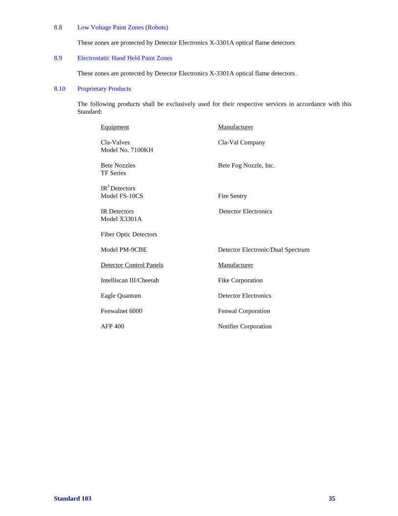
Standard 103 35
8.8 Low Voltage Paint Zones (Robots)
These zones are protected by Detector Electronics X-3301A optical flame detectors
8.9 Electrostatic Hand Held Paint Zones
These zones are protected by Detector Electronics X-3301A optical flame detectors .
8.10 Proprietary Products
The following products shall be exclusively used for their respective services in accordance with this
Standard:
Equipment Manufacturer
Cla-Valves Cla-Val Company
Model No. 7100KH
Bete Nozzles Bete Fog Nozzle, Inc.
TF Series
IR3 Detectors
Model FS-10CS Fire Sentry
IR Detectors Detector Electronics
Model X3301A
Fiber Optic Detectors
Model PM-9CBE Detector Electronic/Dual Spectrum
Detector Control Panels Manufacturer
Intelliscan III/Cheetah Fike Corporation
Eagle Quantum Detector Electronics
Fenwalnet 6000 Fenwal Corporation
AFP 400 Notifier Corporation
Standard 103 36
9.0 Gaseous Agent Acceptance tests
9.1 General
An acceptance t est shall be conducted in the form of a functional test and door fan test for all gaseous
agent systems. The functional tests involve testing of all system components i.e. system control panel,
power supply, emergency power, detectors, time delay devices, alarm devices, selector valves, release
devices for doors and dampers, emergency shut-down and manual releases, without discharging gaseous
agent.
Also, the functional test shall include an examination of the system piping, nozzles and storage cylinders.
A door fan test shall be performed to determine that the space will hold the required concentration of the
gaseous agent should it actually be released during a fire emergency. Trained personnel shall perform all
functional and door fan tests.
Specifications shall state which contractor is responsible for 1) room integrity, 2) who makes repairs if
fan door test fails and pays for retest and 3) provides alarm wiring back to security panel.
For the system to activate, detectors must operate. Two detectors on separate zones (cross-zone or
counting zones) or a manual pull station would have to operate to actuate system discharge. Cross-
zoning is when two detectors, each on a separate circuit, operate to actuate the gaseous agent charge.
Counting zones is when two detectors, on the same circuit, operate to actuate the gaseous agent
Detectors initiate a signal to the control panel that sends a discharge signal to the control head and
discharge control valve that in-turn, discharges the agent gas through all nozzles. A pre-determined
percent minimum concentration shall be maintained for 10 minutes. (This 10-minute time is placed in the
fan test computer for calculations)
Before approval of the installation, the contractor shall certify that the system installation is complete,
and that all tests have been successfully completed.
Review and approval of drawing and plans shall have been obtained from a representative of the
insurance carrier.
Satisfactory test results and as-built drawings shall be provided by the installing contractor and shall be
maintained by the G4S Secure Solutions Site Security Manager.
9.2 Functional Tests
The protected enclosure shall be inspected as follows:
1. The room shall be in normal operating condition.
2. Openings that are to be automatically closed upon system actuation shall be in their normal
operating position (doors, dampers, etc.)
3. Ceiling tiles shall be installed along with clips to prevent uplift of the tiles near discharge
nozzles
4. Nozzles shall be checked for obstruction and securely fastened to the pipe.
5. All dust and debris shall be vacuumed clean, especially from beneath a raised floor space.
Agent and containers shall be inspected as follows:
Agent storage containers shall be properly located in accordance with system design drawings.
Containers and mounting brackets shall be securely fastened in accordance with manufacturer’s
requirements.
Containers for the agent shall be weighed before being placed in-service.

Standard 103 37
The electrical system shall be inspected as follows:
Wiring systems shall be installed in compliance with local codes, GRC and system design drawings.
Field circuitry shall be measured for ground fault and short circuit condition. When measuring field
circuitry, all electric components shall be removed and jumpers properly installed to prevent the
possibility of damage within these devices. Replace components after measuring.
All auxiliary functions, including sounding of alarms, damper and door closer actuation, HVAC
shutdown and equipment shutdown shall be inspected for proper operation in accordance with system
requirements and design specifications.
The piping distribution system shall be cleaned internally to remove oil or foreign material from within
the pipe.
Detectors shall not be located near obstructions or HVAC equipment that would affect their response
characteristics.
For systems with a main/reserve cylinder bank, the main/reserve switch shall be properly installed,
readily accessible and clearly identified.
9.2.2 System Operations
Activation of any one detector on the ceiling or in the under-floor of the protected area will cause the
following to occur:
1. The pre-alarm bell/alarm will ring/sound and send a signal to the building fire alarm system.
2. The “First Zone” lamp on the control panel will illuminate.
3. The auxiliary first detector relay will activate. Door holders will release doors.
4. The activated smoke detector will have its indicating L.E.D. lit bright red (steady). The
corresponding light on the graphic annunciator panel if provided will light and lock-in
indicating that the detector is in alarm.
5. Upon verifying the cause of the alarm, the audible alarm may be silenced by momentarily
operating the “System Alarm Silence” switch. The “System Alarm Silence” indicator will light
and remain lit.
6. To reset the system after an alarm, momentarily operate the “System Reset” switch. The alarm
indicator lights will go “out” and signaling device LEDs will shut-off. If the same alarm
indicator re-occur when the “System Reset” switch is released, the initiating alarm condition has
not been cleared.
Activation of a second detector or “Second Zone” detector on the ceiling or in the under-floor of the
protected area will cause the following to occur:
1. The alarm bell/alarm will ring/sound and the warning strobe lights will activate (unless
previously silenced during the first alarm) and send a signal to the building fire alarm system.
2. The “Second Zone” alarm light will illuminate.
3. Control/Computer equipment will be shutdown automatically.
4. HVAC equipment will be shutdown automatically.
5. Dampers will close automatically.
6. The “Discharge Pending” light will illuminate. The panel may be equipped with an optional
digital count display indicating the time remaining before discharge Normal delay time is 20
sec.
7. Corresponding detector lamps on the graphic annunciator panel will illuminate.
8. The system will discharge at the end of the 15 to 20 second time delay period unless discharge
is interrupted.
Standard 103 38
9.3 Discharge Tests (Door Fan Test)
A door fan test shall be conducted on all gaseous agent protected spaces to determine room integrity. A
contractor that is trained in the use of the testing equipment shall be utilized.
Guidelines for the testing shall be as per NFPA No. 2001 and GRC.
NOTE: Specifications shall state which contractor is responsible to make repairs to room should
the door fan test fail and who will pay for the retest.

Standard 103 39
10.0 Detection System Acceptance tests
10.1 General
An acceptance test shall be conducted in the form of a functional test on all fire detection systems. A
functional test involves testing of all system components of a detection system.
Before approval of the installation, the contractor shall certify that the system installation is complete and
that all pre- tests have been successfully completed.
Satisfactory test results (provided by the installing contractor) and record drawings shall be provided by
the installation contractor and shall be maintained by the G4S Secure Solutions Site Security Manger.
10.2 Fire Control Release Panel
All control equipment shall be tested to ensure its intended function as follow:
A visual inspection on all cable terminals, plug interconnections, plug-in circuit components, lamps,
socket and controls to establish that their mechanical and electrical connections and mounting are as
required for intended function and where applicable, to confirm the electrical supervision of the
equipment.
All field wiring shall be terminated on a single conductor per terminal.
All lamps and indicators shall be tested.
All control unit functions shall be operated to verify appropriate response.
Simulation of open circuits, short circuits and ground faults shall be performed on all relevant circuits in
order to confirm the appropriate electrical supervisory responses.
10.3 Detectors
10.3.1 Smoke Detectors
All brands of smoke detectors are tested in the same manner. This test consists of spraying a smoke
detector test aerosol into the detector chamber. Each detector has a self-contained light that illuminates
flashes or loses illumination when the detector operates.
10.3.2 Heat Detectors
Non-restorable heat detectors cannot be tested by application of heat. Once they have detected enough
heat to create an alarm, they must be replaced. Instead, these detectors are tested by using a piece of
insulated electrical wiring to jumper across the electrical contacts on the base of the detector unit.
Detectors must be removed from their electrical outlet boxes to perform this test.
Rate-of-rise and rate compensation detectors can be tested using a hair dryer or shielded heat lamp. If
the detector contains a fixed temperature element in addition to the rate-of-rise feature, remove the heat
source immediately after the rate-of-rise portion operates (rate-of-rise detection operates faster than the
fixed temperature). If it is not removed, the fixed temperature element could melt thus requiring the
detector to be replaced.
Standard 103 40
10.4 Initiating and Annunciating Devices
10.4.1 Manual Release Stations
Manual release stations, with protective hinged covers, shall be located at exits, stairs, and in corridors.
Unless other specified by the local AHJ, agent shall be released:
1. Immediately after activation if installed outside the door to the hazard.
Functional testing of manual release stations consists of activating the station in the manner indicated on
the device. Movement of the face causes movement of a toggle or momentary contact switch inside the
device. This movement of the switch, in turn, causes a fire alarm to be transmitted to the fire alarm
control panel.
Manual release stations must be dual action type. Resetting is accomplished by use of a key, screw driver
or allen-wrench. For non-coded stations, the face of the station needs to be opened to reset the station.
10.4.2 Alarm Signaling Appliances
Alarm signaling appliances shall be activated to ensure that they function properly.
Audible Signal Appliances – The fire detection system shall be tested on main power supply and standby
power supply with the maximum expected load on the system. Audible signal appliances shall operate
and shall be audible throughout the protected area with normal background noise present.
Visual Signal Appliances – the visual signal appliances shall function as intended and shall be clearly
visible from all points within the visual alarm area.
10.4.3 Voice Alarm Systems
The voice alarm system consists of a power supply, pre-amplifier, amplifier, loudspeakers, digitized
voice module and interconnecting wiring. Upon actuation of a fire alarm within the building, the
digitized voice module sends a pre-recorded message over the voice fire alarm circuit. The message is
amplified and given to occupants through individual loudspeakers. Some voice alarm systems use a live
voice message spoken into a microphone at a central location instead of digitized voice module. Voice
messages sometimes have pre-alert tones for drawing attention to the message that follows.
Voice modules can be inoperative because of mechanical problems. Loudspeakers are either standard
speakers wired in series or supervised speakers with transformers and capacitors wired in parallel.
Transformers in parallel speakers have taps of various wattage ratings for different alarms/messages.
Operating the digitized voice module and making sure that speaker’s circuits are operational ,tests the
voice messages. All speakers shall be tested for proper operation.
10.4.4 Power Supply
The power supply to the detection system shall be inspected to ensure that:
1. It is fused within the requirements of the system.
2. It is not vulnerable to unauthorized interruption.
3. It is adequate to meet the requirements of the system.
4. The control panel circuit breaker is identified in the panel and is locked.
Power for auxiliary devices is taken from a source separate from the fire alarm system control panel
source in such a way that a fault of an auxiliary device circuit shall not detrimentally affect the fire alarm
system power supply.
Standard 103 41
Standby Power Supply (batteries) shall be inspected to verify that they are:
1. Not damaged
2. Protected from accidental damage
3. Provided with adequate ventilation
4. Connected to a properly fused charging circuit
Standby batteries shall be capable of operating the fire alarm system with the charger input disconnected
for one rated load cycle. A rated load cycle means the total energy consumed by the maximum electrical
supervisory current plus the trouble signal current for 24 hours followed by the general alarm load for
fifteen minutes.
If generators act as the standby power supply, an inspection and test shall be made to establish that the
transfer to standby power functions properly and that the generator starts and exercises itself without
applying unacceptable voltages to control equipment.
Initiating devices shall be activated with the main power supply disconnected to verify operation of the
backup power supply.
The batteries must be marked with the date they were placed in service with a waterproof marker.
10.4.5 Electrically Supervised Circuits
Electrical connections for each device shall be tested to ensure that disconnection of the device from the
circuit or improper wiring will activate the required electrical supervisory signals as follows:
In response to open circuits, short circuits, ground faults and the disconnection of plug-in components.
Individual terminations of conductors and circuit polarities shall also be observed.
10.4.6 Auxiliary Equipment
Equipment shall be inspected to ensure that faults in the auxiliary equipment do not interfere with the
normal operation of the fire alarm system.
10.5 Trouble Shooting during Acceptance testing
If a system fault is established, investigate the following:
Check the AC power-on light to ensure its normal operation (if main power supply failure is not
electrically supervised)
Check the principle and remote trouble lights for trouble indication at the control panel.
The remote annunciator panel shall be checked to ensure that the tested devices annunciate correctly.
Check the operation of manual pull stations.
Fire alarm batteries shall be checked to ensure that:
1. Terminals are clean and lubricated.
2. Terminal clamps are clean and tight.
3. Electrolyte level and specific gravity are as specified by the manufacturer.
Operate every audible and visual signal appliance to verify proper operation and supervision.
The fire alarm system control panel shall be visually inspected to ensure that the control panel has not
been altered from its designed intent.
Standard 103 42
11.0 Carbon Dioxide System Acceptance tests
11.1 General
An “acceptance” test shall be conducted in the form of a functional and discharge test for all carbon
dioxide systems. The functional tests involve testing of all system functions and components i.e. system
control panel, power supply, emergency power, detectors, time delay devices, alarm devices, selector
valves, release devices for doors and dampers, pilot line supervision, emergency shut-down and manual
releases. These tests shall be completed without discharging carbon dioxide (control heads are removed
prior to test).
Also, the functional test shall include an examination of the system piping, nozzles and carbon dioxide
storage cylinders/tanks. A discharge test involves tripping the system by any means to achieve design
concentration of carbon dioxide in the protected area(s). Trained personnel shall perform all functional
and door fan tests.
A 3 point recording meter that records carbon dioxide concentration is required to detect percentage of
carbon dioxide concentration by volume of air. A portable exhaust fan may be required for post test
ventilation. The carbon dioxide exhaust must be to a safe location or dilute the concentration into the air.
A detector or manual release station would have to operate to actuate carbon dioxide discharge. These
devices initiate a signal in the control panel, operating the control heads (high pressure system), selector
valves (high or low-pressure system) and discharge control valve that in turn, discharges carbon dioxide
gas through all nozzles. Designed concentration shall be recorded during the test.
Before approval of the installation, the contractor shall certify that the system installation is complete and
that all tests have been successfully completed.
Satisfactory test results and record drawings shall be provided by the installing contractor and shall be
maintained by the G4S Secure Solutions Site Security Manager.
11.2 High Pressure
11.2.1 High Pressure Storage
High-pressure containers (cylinders) are designed to store liquid carbon dioxide at atmospheric
temperature. Since maximum pressure in the cylinder is 800 to 1,000 PSI for carbon dioxide at ambient
temperature, the container shall be designed to withstand maximum expected pressure.
Storage cylinders are designed, tested and filled to U.S. Department of Transportation (DOT)
specifications. The maximum permitted filling density is equal to 68% of the weight of water that the
container can hold at 60°F. Cylinders are fitted with an internal dip tube so that liquid will be discharged
from the bottom when the cylinder is upright and the valve is opened.
Abnormally low storage temperatures would adversely affect the rate of discharge. For this reason,
storage temperature below 0°F for total flooding systems or below 32°F for local application systems are
not permitted.
Standard 103 43
11.2.2 Functional Tests
The protected enclosure shall be inspected as follows:
- The room shall be in normal operating condition.
- Taping and other non-permanent methods may be allowed for discharge tests if design
conditions can be simulated.
- Openings that are to be automatically closed upon system actuation shall be in their
normal operating position (doors, dampers, etc.)
- Ceiling tiles shall be installed and clipped to prevent uplift.
- Nozzles shall be checked for obstruction. Loose paper and lightweight materials that
may be moved by the discharge of the carbon dioxide shall be removed.
- All dust and debris shall be vacuumed clean, especially from beneath a raised floor
space. This will minimize the potential damage to equipment.
Provisions shall be provided for removal of the carbon dioxide after discharges tests are completed.
Agent and containers shall be inspected as follows:
1. Agent storage containers shall be properly located in accordance with system design drawings.
2. Containers and mounting brackets shall be securely fastened in accordance with manufacturer’s
requirements.
3. Containers for the agent to be used during testing shall be weighed before and after discharge.
4. The electrical system shall be inspected as follows:
5. Wiring systems shall be installed in compliance with local codes, insurance carrier and system
design drawings.
6. Field circuitry shall be measured for ground fault and short circuit condition. When measuring
field circuitry, all electric components shall be removed and jumpers properly installed to
prevent the possibility of damage within these devices. Replace components after measuring.
7. All auxiliary functions, including sounding of an alarms, remote annunciator, damper and door
closer actuation, HVAC shutdown and equipment shutdown shall be inspected for proper
operation in accordance with system requirements and design specifications.
8. The piping distribution system shall be cleaned internally to remove oil or foreign material from
within the pipe. A rag placed over each nozzle during the discharge test is a satisfactory
substitute for cleaning the pipe, as it would collect oil and foreign materials as agent blows
through the pipe.
Detectors shall not be located near obstructions or HVAC equipment that would affect their response
characteristics.
For systems with a main/reserve cylinder bank, the main/reserve switch shall be properly installed,
readily accessible and clearly identified.
Standard 103 44
11.2.3 System Operations
Activation of any one detector on the ceiling or in the under-floor of the protected area will cause the
following to occur:
The pre-alarm bell/alarm will ring/sound.
1. The “ Zone” lamp on the control panel will illuminate.
2. Door holders will release doors.
3. HVAC will shutdown.
4. Dampers will close.
5. Equipment/fuel supply or supplies will shutdown.
6. The indicating light for the activated detector will illuminate at the control panel. The
corresponding light on the graphic annunciator panel (if applicable) will light indicating that the
detector is in alarm mode.
7. After a pre-determined time delay (30 to 60 seconds), the system will discharge. Normal delay
time is 30 sec.
8. Upon verifying the cause of the alarm, the audible alarm may be silenced by momentarily
operating the “System Alarm Silence” switch. The “System Alarm Silence” indicator will light
and remain lit.
9. To reset the system after an alarm (discharge), momentarily operate the “System Reset” switch.
The alarm indicator lights will go “out” and signaling device lights will shutoff. If the same
alarm indicator re-occur when the “System Reset” switch is released, the initiating alarm
condition has not been cleared.
11.2.4 Discharge Tests
For total flooding systems, a listed or approved 3 point concentration meter shall be used. The meter
shall be calibrated in strict accordance with the manufacturer’s instructions. Concentration readings shall
be taken at three levels. Sampling points shall be located at least six inches above the floor, above the
highest equipment and at any intermediate level. If more than one area is simultaneously protected, a
sampling point shall be located in each space in accordance with the above criteria. Electric power (110
volts) shall be available for operating the meter.
Minimum design concentration of the hazard shall be achieved at all sampling points at the completion of
the initial discharge and shall be maintained for period after the initial discharge as required by code
requirements and the Authority Having Jurisdiction (AHJ). For flammable liquids and gases, the
minimum specified concentration shall be achieved, but does not need to be maintained. Hazards
involving deep-seated combustibles require design concentrations for an extended period of time as
determined by code requirements and the Authority Having Jurisdiction. Safety limits specified in NFPA
No. 12 shall not be exceeded.
The following procedures shall be used for the discharge test:
1. Carbon dioxide analyzers shall be calibrated prior to each test.
2. If the system is alarmed to a central station monitor system, notify the appropriate authorities
prior to and at completion of the test.
3. Concentration will be reported for the predetermined time period.
4. Liquid discharge shall meet design criteria in accordance with NFPA No. 12.
5. Once the requirement for the “hold” time has been completed, ventilation to exhaust the carbon
dioxide from the area shall be initiated.
Standard 103 45
Activation of any one (1) detector on the ceiling of the protected area will cause the following to occur:
(requires 2 detectors to discharge the system)
1. The pre-alarm bell/alarm will ring/sound and send a signal to the building fire alarm system.
2. The “ Zone” lamp on the control panel will illuminate.
3. Door holders will release doors.
4. HVAC will shutdown.
5. Dampers will close.
6. Equipment/fuel supply or supplies will shutdown.
7. The indicating light for the activated detector will illuminate at the control panel. The
corresponding light on the graphic annunciator panel (if applicable) will light indicating that the
detector is in alarm mode.
8. The system will not discharge with one detector in alarm.
9. Upon verifying the cause of the alarm, the audible alarm may be silenced by momentarily
operating the “System Alarm Silence” switch. The “System Alarm Silence” indicator will light
and remain lit.
10. To reset the system after an alarm (discharge), momentarily operate the “System Reset” switch.
The alarm indicator lights will go “out” and signaling device lights will shutoff. If the same
alarm indicator re-occur when the “System Reset” switch is released, the initiating alarm
condition has not been cleared.
Upon activation of the second detector the system will discharge after a 30-60 second time delay.
11.2.5 Resetting the System
After the system has been discharged, the system is reset as follows:
1. If a manual pull station was “used”, reset the pull station.
2. Momentarily depress the “System Reset” switch on the control panel.
3. Silence the trouble signal. The panel will remain in trouble mode until the control head is reset.
4. Open doors and activate room fans.
5. Recharge carbon dioxide cylinders
11.2.6 Pneumatic Time Delay and Sirens
See section 11.3.7
11.3 Low Pressure
11.3.1 Low Pressure Storage
Low-pressure storage tanks are pressure vessels with a designed working pressure of approximately 300
PSI. Storage tanks are maintained at a temperature of approximately 0 degrees Fahrenheit by use of
insulation and mechanical refrigeration. At this temperature, the pressure is approximately 300 PSI. A
compressor, controlled by a pressure switch in the tank, circulates refrigerant through the coils near the
top of the tank. Tank pressure is controlled by condensation of carbon dioxide vapors by the coils. In
the event refrigeration fails, pressure relief valves bleed off some vapors to keep the pressure within safe
limits. This permits some of the liquid to evaporate, creating a self-refrigerating effect that keeps the
emergency loss rate at a low level.
With low-pressure storage, it is common practice to protect multiple hazards from one central storage
tank. Opening and closing the discharge (selector) valves using preset timed sequence controls the
quantity of carbon dioxide discharged in a protected area. Central storage tanks may have capacities
ranging from less than one ton to one hundred tons. For large protected areas, the distance between the
hazard and storage could be as much as several hundred feet.

Standard 103 46
11.3.2 Extended Discharge
An extended discharge of carbon dioxide is used when an enclosure is not tight enough to retain an
extinguishing concentration as long as it is needed. The extended discharge is discharged at a reduced
rate following the initial discharge used to develop the extinguishing concentration (within a two-minute
time frame). The reduced rate of discharge shall be a function of the leakage rate (calculated by leakage
area), or the flow rate, through ventilation ducts that cannot be shut down.
Extended discharge is particularly applicable to enclosed rotating electrical equipment such as
generators, where it is difficult to prevent leakage until rotation stops. Extended discharge can be
applied to ordinary total flooding systems as well as to local application systems where a small spot may
require prolonged cooling.
11.3.3 Hand Held Hose Lines
Hand held hose lines are not to be installed at Chrysler Group LLC Facilities
11.3.4 Functional Tests
The protected enclosure shall be inspected as follows:
1. The room shall be in normal operating condition. Taping and other non-permanent methods
may be allowed for discharge tests if design conditions can be simulated.
2. Openings that are to be automatically closed upon system actuation shall be in their normal
operating position (doors, dampers, etc.)
3. Ceiling tiles shall be installed, if applicable.
4. Nozzles shall be checked for obstruction. Loose paper and lightweight materials that may be
moved by the discharge of the carbon dioxide shall be removed.
5. All dust and debris shall be vacuumed clean, especially from beneath a raised floor space. This
will minimize the potential damage to equipment.
6. Provisions shall be provided for removal of the carbon dioxide after discharges tests are
completed.
Agent and containers shall be inspected as follows:
1. Agent storage containers shall be properly located in accordance with system design drawings.
2. Containers and mounting brackets shall be securely fastened in accordance with manufacturer’s
requirements.
3. Containers for the agent to be used during testing shall be weighed before and after discharge.
The electrical system shall be inspected as follows:
1. Wiring systems shall be installed in compliance with Local codes, GRC and system design
drawings.
2. Field circuitry shall be measured for ground fault and short circuit condition. When measuring
field circuitry, all electric components shall be removed and jumpers properly installed to
prevent the possibility of damage within these devices. Replace components after measuring.
3. All auxiliary functions, including sounding of an alarms, remote annunciator, damper and door
closer actuation, HVAC shutdown and equipment shutdown shall be inspected for proper
operation in accordance with system requirements and design specifications.
The piping distribution system shall be cleaned internally to remove oil or foreign material from within
the pipe. A rag placed over each nozzle during the discharge test is a satisfactory substitute for cleaning
the pipe, as it would collect oil and foreign materials as agent blows through the pipe.
Detectors shall not be located near obstructions or HVAC equipment that would affect their response
characteristics.
For systems with selector valves, selector valves shall be properly installed, readily accessible and the
zone it protects shall be clearly identified.
Standard 103 47
11.3.5 System Operations
Activation of any one detector on the ceiling of the protected area will cause the following to occur:
1. The pre-alarm bell/alarm will ring/sound and send a signal to the building fire alarm system.
2. The “ Zone” lamp on the control panel will illuminate.
3. Door holders will release doors.
4. HVAC will shutdown.
5. Dampers will close.
6. Equipment/fuel supply or supplies will shutdown.
7. The indicating light for the activated detector will illuminate at the control panel. The
corresponding light on the graphic annunciator panel (if applicable) will light indicating that the
detector is in alarm mode.
8. After a pre-determined time delay (30 to 60 seconds), the zoned selector valve will open and the
system will discharge the system will not discharge on the activation of one detector.
9. After a predetermined discharge time, selector valves will close.
10. Upon verifying the cause of the alarm, the audible alarm may be silenced by momentarily
operating the “System Alarm Silence” switch. The “System Alarm Silence” indicator will light
and remain lit.
11. To reset the system after an alarm (discharge), momentarily operate the “System Reset” switch.
The alarm indicator lights will go “out” and signaling device lights will shutoff.
12. If the same alarm indicator re-occur when the “System Reset” switch is released, the initiating
alarm condition has not been cleared.
11.3.6 Discharge Tests
For total flooding systems, a listed or approved 3 point concentration meter shall be used. The meter
shall be calibrated in strict accordance with the manufacturer’s instructions. Concentration readings shall
be taken at three levels. Sampling points shall be located at least six inches above the floor, above the
highest equipment and at any intermediate level. If more than one area is simultaneously protected, a
sampling point shall be located in each space in accordance with the above criteria. Electric power (110
volts) shall be available for operating the meter.
Minimum design concentration of the hazard shall be achieved at all sampling points at the completion of
the initial discharge and shall be maintained for period after the initial discharge as required by code
requirements and the Authority Having Jurisdiction (AHJ). For flammable liquids and gases, the
minimum specified concentration shall be achieved, but does not need to be maintained. Hazards
involving deep-seated combustibles require design concentrations for an extended period of time as
determined by code requirements and the Authority Having Jurisdiction. Safety limits specified in NFPA
No. 12 shall not be exceeded.
The following procedures shall be used for the discharge test:
1. Carbon dioxide analyzers shall be calibrated prior to each test.
2. If the system is alarmed to a central station monitor, notify the appropriate authorities prior to
and at completion of the test.
3. Concentration will be reported for the predetermined time period that the Authority Having
Jurisdiction has determined to be appropriate for that particular occupancy.
4. Liquid discharge shall meet design criteria in accordance with NFPA No. 12.
5. Once the requirement for the “hold” time has been completed, ventilation to exhaust the carbon
dioxide from the area shall be initiated.
6. The tank will be refilled by the installing contractor.
Although local application systems are not subject to concentration testing, their effectiveness is judged
by observation to see that carbon dioxide flows through each nozzle, and to see that carbon dioxide
accumulates in the protected area during discharge.
Standard 103 48
11.3.7 Pneumatic Time Delay and Sirens
1. Provide a pneumatic time delay and siren for all occupiable spaces as outlined in NFPA No. 12
2. These delays and signals shall be tested when the discharge test is conducted.
Standard 103 49
12.0 Wet/Dry Chemical System Acceptance tests
12.1 General
All new wet chemical systems shall meet UL 300 Standard.
An acceptance test shall be conducted in the form of a functional test for wet/dry chemical systems and
an optional balloon test (only for dry chemical systems). A functional test involves testing of all system
components of the chemical system. Before approval of the installation, the contractor shall certify that
the system installation is complete and that all tests have been successfully completed.
Satisfactory test results and record drawings shall be provided by the installing contractor and shall be
maintained by the G4S Secure Solutions Site Security Manager.
12.2 Functional Tests
Functional tests shall be performed on all system components without discharging chemical agent.
Discharge tests, when required by the Authority Having Jurisdiction, can be performed by discharging
chemical agent through system piping, with collection in bags at nozzles (bag test). Some manufacturers
do not recommend discharge tests because of the possibility that chemical agent remaining in piping
could moisten and clog piping. Balloon tests (performed on dry chemical systems only), require piping
to be blown out with air prior to resetting the system.
Shutoff valves and switches shall be tested to ensure their operability in conjunction with system
operation.
Piping and nozzles shall be inspected to assure proper types and locations.
Accessories include:
1. Remote Manual Pull Station
2. Mechanical Gas Shut-off Valve(s)
3. Electric/ Gas shut-off Valve(s)
4. Electrical Switch(s)
5. Pressure Switch(s)
12.3 Balloon Tests
Discharge (balloon) tests are required. A balloon shall be placed securely over each discharging nozzle.
The manual release can be operated or the fusible link broken, removed or melted for actuation. This
discharges gas (expellant) into dry chemical cylinders, that forces dry chemical power through the piping
and out the various nozzles. The contents of each balloon should be weighed to determine how much
chemical agent it contains. Each nozzle should discharge at least 2 pounds of powder and each duct or
plenum nozzle should discharge at least 5 pounds of powder. If lesser amounts are collected from any
nozzle, the piping should be checked for blockage.
Check operation of pressure switches and auxiliary equipment connected to the system control panel/box
and the cooking equipment power supply shutoff.
Upon completion of testing dry chemical systems, replace the expelled dry chemical agent in the
cylinders and gas (expellant) cartridges. Restore the system to normal service.
For functional tests, the same procedure is followed as for the balloon test except that chemical agent is
disconnected prior to operation of the system.

Standard 103 50
12.4 Manual Release- Dual Action
A “STRIKE” button is a manual release device and is located on the face of the mechanical release
mechanism.
A remote manual release station allows the system to be manually operated at some point distant from the
release mechanism. The manual pull station shall be installed at a height convenient for the manual
operation and located in the exit path. The manual pull station becomes either a primary or secondary
source of manual actuation depending on accessibility of the “STRIKE” button on the face of the release
mechanism (which is sometimes acceptably inaccessible).
Manual release stations shall be located within 25 feet of the release mechanism. The maximum number
of pulley elbows that may be used per system is twelve.
12.5 Test Procedures
After the system has been installed (excluding accessories), and before installing the cartridge, a
functional test shall be performed as follows:
1. Raise the tension level to the “up” position.
2. Remove the fusible link from the terminal detector and install a test link.
3. Lower tension level to the “down” position.
4. Locate detector linkage assembly and center in each bracket.
5. Using a wire cutter, cut the test link at the terminal detector to simulate automatic actuation.
If the release mechanism does not actuate, check the following components as follows:
Check to see that the detector linkage is centered in each bracket, and make certain wire rope is
positioned on linkage.
1. Check the wire rope for knotting or jamming.
2. Check pulley elbows to see that the wire rope is free and centered in pulley sheaves. If evidence
of pulley elbow deformation is found, replace the pulley elbow.
3. Make certain that the lock bar is removed.
4. Make certain that the release mechanism is cocked.
5. Make certain that tension lever is in the “down” position.
6. Check for ¼ inch clearance between the trip hammer assembly and the cable lever assembly.
Upon successful actuation of the system, test the manual release by:
Cocking the release mechanism and testing it by manually operating the red “Strike” button and all
remote pull stations.
Upon satisfactory functional test results (and balloon test, if applicable), place the system in operation
mode as follows:
1. Insert the lock bar to prevent tripping the system during cartridge installation.
2. Before installing cartridge, all accessory equipment shall be functional and in operating mode.
3. Screw cartridge into the release mechanism receiver and hand tighten.
4. Remove the lock bar.
5. Insert ring pin through red “Strike” button and attach a wire seal.
6. All discharge piping is blown out with air to remove the dry chemical residue.
(NOTE: There is a new class of fire known as a Class ‘K’. The agent is electrically conductive and
therefore, it is critical that the total flooding agent discharge shuts off electrical power before anyone
discharges a portable Class K extinguisher.

Standard 103 51
13.0 Water Mist Systems
13.1 General
NFPA No. 750 contains the definition of water mist as “water spray with 99 percent of the mass of water
contained in drops with diameters less than 1 mm (Dv0.99<1000 microns), measured in the coarsest part of the
spray a distance of 1 meter below the nozzle”. Proposed change for 1999 code will hope to change to “the
Dv0.99 of the weigh-average cumulative percent volume distribution curve for water mist shall be 1000 microns
or less”. An appendix note will describe how to obtain such a curve.
Chrysler Group LLC, at the present time, does not recognize water mist systems as a acceptable fire
suppression system